Embed Size (px)
Citation preview

Requirements for
Electrical Service Connection
Seattle City Light Customer Engineering
4/5/2018

Table of Contents
1. Getting Started: Initial Requirements for Electrical Service ...................................................... 5
1.1. Service Areas .................................................................................................................... 5
1.2. Advance Notice ................................................................................................................ 5
1.3. Submission of Plans .......................................................................................................... 6
1.4. Service Contracts .............................................................................................................. 7
1.5. Permit ............................................................................................................................... 7
1.6. Energy Code Compliance and Requirements ................................................................... 7
1.7. Service Connection Prerequisites ...................................................................................... 7
2. Easements .......................................................................................................................................... 8
2.1. Determination ................................................................................................................... 8
2.2. Property Description ......................................................................................................... 8
2.3. Verification........................................................................................................................ 8
3. Clearance Requirements ................................................................................................................. 9
3.1. Overhead Clearance ......................................................................................................... 9
3.2. Service Drop Conductor Clearances ............................................................................... 10
4. Temporary Service ......................................................................................................................... 11
4.1. General Requirements .................................................................................................... 11
4.2. Temporary Overhead Service.......................................................................................... 12
4.3. Temporary Underground Service ................................................................................... 13
5. Types of Secondary Service .......................................................................................................... 14
5.1. Phases of Service: Single Phase and Three Phase ........................................................... 14
5.2. Voltages Available .......................................................................................................... 14
5.3. Service Sizes: Ampacity ................................................................................................... 15
5.4. Transformation by Customer .......................................................................................... 16
5.5. Secondary Overhead Services ......................................................................................... 16
5.6. Secondary Underground Services ................................................................................... 17
5.7. Mobile Home Services .................................................................................................... 19
5.8. Houseboat Installations .................................................................................................. 19
6. Equipment for Service Installation .............................................................................................. 21
6.1. Overhead Services .......................................................................................................... 21
6.2. Underground Services .................................................................................................... 23
7. Primary Services in Non-Network Areas .................................................................................... 27
7.1. Vault Construction in Non-Network Areas ..................................................................... 28

7.2. Vault Structure Requirements ......................................................................................... 28
7.3. Vault Grounding ............................................................................................................. 29
7.4. Vault Ventilation ............................................................................................................. 30
7.5. NEC-sized Service Entrance Outside Network Areas ...................................................... 31
8. Primary Services in Network Areas ............................................................................................. 33
8.1. Vault Construction in Network Areas.............................................................................. 33
8.2. Structure Requirements .................................................................................................. 34
8.3. Vault Construction Guidelines ........................................................................................ 35
8.4. Secondary Underground Service in Network Areas ........................................................ 36
8.5. Residential Services to First Hill, South Lake Union and University District Networks .... 36
9. Primary Underground: Transformer Pad Construction ............................................................ 37
9.1. Transformer Pad Dimensions .......................................................................................... 37
9.2. Construction ................................................................................................................... 37
9.3. Oil Containment ............................................................................................................. 38
9.4. Pad Grounding ............................................................................................................... 39
9.5. Service Termination Facility ............................................................................................ 39
10. Maintenance of Conductors and Division of Responsibility ................................................... 41
10.1. Primary Underground Service ......................................................................................... 41
10.2. Poles ............................................................................................................................... 41
10.3. Metering Equipment ....................................................................................................... 41
10.4. Maintenance of Underground Conductors ..................................................................... 42
11. Metering .......................................................................................................................................... 43
11.1. Meter Sockets: Construction Guidelines ......................................................................... 43
11.2. Temporary Totalization Metering ................................................................................... 44
11.3. Metering Voltages .......................................................................................................... 44
11.4. Service Entrance Conductors for Metered Loads ............................................................ 44
11.5. Conductor Connections .................................................................................................. 45
11.6. Service Entrance Equipment Sequencing........................................................................ 45
11.7. Master Metering ............................................................................................................. 45
11.8. Special Metering Requirements for Multi-Unit Buildings ............................................... 46
11.9. Provisions for Automated Metering ............................................................................... 46
11.10. Multiple Metering Equipment Room .............................................................................. 46
11.11. Metering Equipment Location ........................................................................................ 47
11.12. Meter Height .................................................................................................................. 48
11.13. Access to Metering Equipment ....................................................................................... 48
11.14. Protection of Metering Equipment ................................................................................. 49
11.15. Ownership of Metering Equipment ................................................................................ 49
11.16. Current Transformer-Rated Metering ............................................................................. 49

11.17. Current Transformer Landing Pads and Enclosures ........................................................ 50
11.18. Secondary Wiring for Transformer-Rated Meters ........................................................... 50
11.19. Metering on Switchboards ............................................................................................. 51
11.20. Net Metering .................................................................................................................. 51
11.21. Communications Provisions for Large Metered Loads ................................................... 52
12. Motors and Special Loads ............................................................................................................. 54
12.1. Motor-Starting Limitations ............................................................................................. 54
12.2. Starting Limitations on Single-Phase Motors ................................................................. 54
12.3. Starting Limitations on Poly-Phase Motors .................................................................... 55
12.4. Approval ......................................................................................................................... 55
12.5. Electric Power Regeneration Due to Moto Drive/Control ............................................... 56
12.6. Intereference of Non-Inductive Loads ............................................................................ 56
12.7. Maxiumum Switched Load ............................................................................................. 56
12.8. Welding Equipment ........................................................................................................ 56
12.9. Minimum Power-Factor Limitations................................................................................ 56
12.10. Special Voltage Requirements ........................................................................................ 56
12.11. Meter Requirements for Large Loads ............................................................................. 57
13. Technical and Special Service Requirements ............................................................................. 58
13.1. Limits of Service and Service Equipment ........................................................................ 58
13.2. Special Technical Provisions ........................................................................................... 58
13.3. Limitations to Specified Service Areas ............................................................................ 59
13.4. Closed Transition Transfer Switches ............................................................................... 59
13.5. Frequency, Phase and Voltage ........................................................................................ 59
13.6. Electromagnetic Interference (EMI) ................................................................................ 61
13.7. Power Surges, Faults Transients and Outages ................................................................ 61
14. Customer Generation .................................................................................................................... 63
14.1. Definitions ...................................................................................................................... 63
14.2. Net Metering .................................................................................................................. 63
14.3. Customer Generation within the City Light Network Service Areas ................................ 64
14.4. Production Metering ...................................................................................................... 65
14.5. Production Meter Locaion Guidelines ............................................................................ 66
SEATTLE CITY LIGHT REQUIREMENTS FOR ELECTRICAL SERVICE CONNECTIONS| PAGE 5
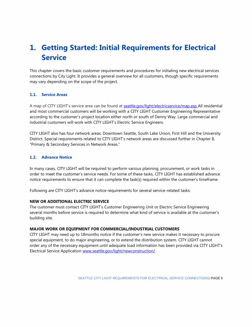
1. Getting Started: Initial Requirements for Electrical
Service
This chapter covers the basic customer requirements and procedures for initiating new electrical services
connections by City Light. It provides a general overview for all customers, though specific requirements
may vary depending on the scope of the project.
1.1. Service Areas
A map of CITY LIGHT’s service area can be found at seattle.gov/light/electricservice/map.asp All residential
and most commercial customers will be working with a CITY LIGHT Customer Engineering Representative
according to the customer’s project location either north or south of Denny Way. Large commercial and
industrial customers will work with CITY LIGHT’s Electric Service Engineers.
CITY LIGHT also has four network areas: Downtown Seattle, South Lake Union, First Hill and the University
District. Special requirements related to CITY LIGHT’s network areas are discussed further in Chapter 8,
“Primary & Secondary Services in Network Areas.”
1.2. Advance Notice
In many cases, CITY LIGHT will be required to perform various planning, procurement, or work tasks in
order to meet the customer’s service needs. For some of these tasks, CITY LIGHT has established advance
notice requirements to ensure that it can complete the task(s) required within the customer’s timeframe.
Following are CITY LIGHT’s advance notice requirements for several service-related tasks:
NEW OR ADDITIONAL ELECTRIC SERVICE
The customer must contact CITY LIGHT’s Customer Engineering Unit or Electric Service Engineering
several months before service is required to determine what kind of service is available at the customer’s
building site.
MAJOR WORK OR EQUIPMENT FOR COMMERCIAL/INDUSTRIAL CUSTOMERS
CITY LIGHT may need up to 18months notice if the customer’s new service makes it necessary to procure
special equipment, to do major engineering, or to extend the distribution system. CITY LIGHT cannot
order any of the necessary equipment until adequate load information has been provided via CITY LIGHT’s
Electrical Service Application www.seattle.gov/light/newconstruction/

REV. 04/20/2018
PAGE 6 | SEATTLE CITY LIGHT REQUIREMENTS FOR ELECTRICAL SERVICE CONNECTIONS
DISCONNECT OF SERVICE OR METER
Small or residential projects which need to have a service or meter disconnected, require advance notice.
Large services and on-site transformers will need a minimum of two months’ notice.
SERVICE EASEMENTS
Where service easements will be required (e.g., when service lines cross one lot to serve another), the
customer shall contact City Light at least three months before the planned service date. For details see
Chapter 2, “Easements.”
CONNECTION
The customer needs to notify CITY LIGHT when the City of Seattle Department of Planning and
Development (DPD) inside Seattle or the State Department of Labor and Industries (L&I) or other agency
outside Seattle, has approved the customer’s service for connection. Additional prerequisites for
connection are discussed throughout this document.
THREE PHASE MOTORS
For advance notice requirements relating to three-phase motors, see Chapter 12, “Motors and Special
Loads.”
1.3. Submission of Plans
For new services or for rewire of existing services (including triplexes or larger multi-residential structures),
the customer shall submit a plan package for CITY LIGHT review and comment.
The plan package shall contain the following elements:
A plan set which includes:
1. A site plan including:
• Any building on the property
• Street designations and project address per DPD or L&I
• Proposed location of service entrance, switch gear, and meter centers
• “North” and directional arrow
• Property boundary designations
2. Legal description(s) (as required)
3. Elevation drawings
4. Diagram of floor plans with unit designation
5. A project schedule
6. A load summary and schedule
7. A paving plan, if applicable
8. Billing and owner information
9. Completion of CITY LIGHT’s Application for Service seattle.gov/light/newconstruction/.
10. A riser diagram showing:
• The size of the main disconnect or bus
• A detailed sketch of the proposed route of service conductors from the service termination point
• to the main disconnector bus
• The size, type, and number service conductors
• Provisions for metering

REV. 04/20/2018
SEATTLE CITY LIGHT REQUIREMENTS FOR ELECTRICAL SERVICE CONNECTIONS| PAGE 7
* Note: Chapter 12, “Motors and Special Loads,” covers submission of plans for motors and special
equipment.
1.4. Service Contracts
The customer may be required to sign a service contract before the electrical service is connected. CITY
LIGHT’s Customer Engineering Representative or Electric Service Engineer, as applicable, will determine
whether a service contract is required and can assist with establishing the terms of the contract.
1.5. Permit
The customer is responsible for obtaining all necessary permits, and for verifying permit requirements
with their local jurisdiction. The customer must pay all permit and inspection fees.
1.6. Energy Code Compliance and Requirements
The customer’s building may have to comply with the all applicable Energy Codes. Customers should
contact their building inspector in the applicable jurisdiction to verify code compliance requirements.
1.7. Service Connection Prerequisites
CHARGES
After receiving customer plans, CITY LIGHT will determine charges for service work based on the size of
the service, the service location, and the work required to connect it to our system. The charges must be
paid prior to the work being done.
CODE AUTHORITY INSPECTION AND APPROVAL
CITY LIGHT will not connect to the customer’s service conductors until the proper code authority has
inspected and approved the service for connection.
SERVICE CONNECTION
CITY LIGHT will make service connections only after all applicable CITY LIGHT requirements have been
met. The customer’s responsibilities as delineated herein, in a service letter, contract and/or agreement
with the Utility must have been fulfilled. All CITY LIGHT inspections must have been completed and the
project approved before connection.
REV. 04/20/2018
PAGE 8 | SEATTLE CITY LIGHT REQUIREMENTS FOR ELECTRICAL SERVICE CONNECTIONS
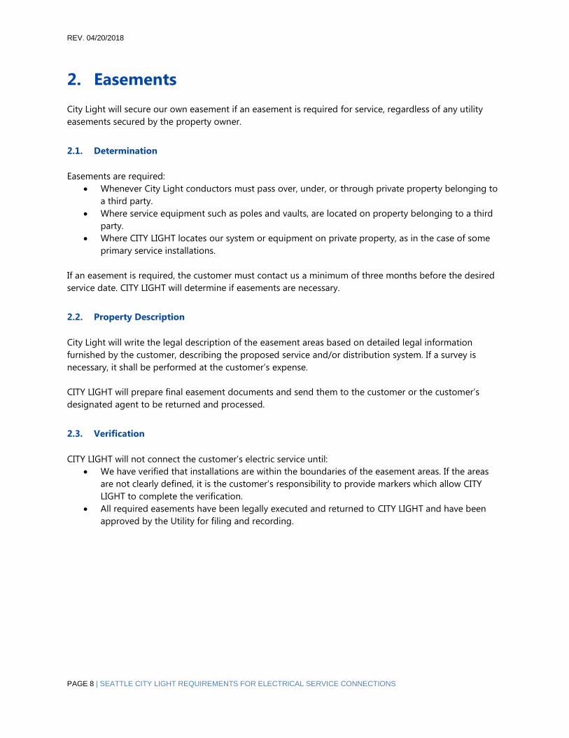
2. Easements
City Light will secure our own easement if an easement is required for service, regardless of any utility
easements secured by the property owner.
2.1. Determination
Easements are required:
• Whenever City Light conductors must pass over, under, or through private property belonging to
a third party.
• Where service equipment such as poles and vaults, are located on property belonging to a third
party.
• Where CITY LIGHT locates our system or equipment on private property, as in the case of some
primary service installations.
If an easement is required, the customer must contact us a minimum of three months before the desired
service date. CITY LIGHT will determine if easements are necessary.
2.2. Property Description
City Light will write the legal description of the easement areas based on detailed legal information
furnished by the customer, describing the proposed service and/or distribution system. If a survey is
necessary, it shall be performed at the customer’s expense.
CITY LIGHT will prepare final easement documents and send them to the customer or the customer’s
designated agent to be returned and processed.
2.3. Verification
CITY LIGHT will not connect the customer’s electric service until:
• We have verified that installations are within the boundaries of the easement areas. If the areas
are not clearly defined, it is the customer’s responsibility to provide markers which allow CITY
LIGHT to complete the verification.
• All required easements have been legally executed and returned to CITY LIGHT and have been
approved by the Utility for filing and recording.

REV. 04/20/2018
SEATTLE CITY LIGHT REQUIREMENTS FOR ELECTRICAL SERVICE CONNECTIONS| PAGE 9
3. Clearance Requirements
This chapter provides basic overhead and underground clearance requirements for both temporary and
permanent services. Clearance requirements for meters, switchboards, and vaults are covered in Chapter
7, “Primary Service in Non‐Network Areas;” Chapter 8, “Primary and Secondary Services in Network Areas;”
and Chapter 11, “Metering. “
WARNING: The clearances indicated in this chapter may no longer be valid. Please contact your Electric
Service Representative (Residential and Commercial) or Electrical Service Engineers (Large Commercial
and Industrial) for the most current information. Refer to the National Electric Code (NEC), National
Electric Safety Code (NESC), and City of Seattle Electrical Codes for further information.
3.1. Overhead Clearance
CLEAR PATH
The path between the service pole and the point of service attachment must be clear of all obstructions
including trees, branches, buildings, and other obstacles.
CONSTRUCTION CLEARANCE
The customer is required to maintain 14 feet minimum working clearance from CITY LIGHT distribution
lines to any person, building sections and construction equipment, according to current Safety Standards
for Construction Work and General Safety and Health Standards. The customer must contact CITY LIGHT
well in advance of starting construction, so we can make temporary modifications to provide working
clearances and determine the costs for the work. All estimated costs shall be paid in advance of CITY
LIGHT doing the work.
PERMANENT CLEARANCES
The standards for clearances from the ground and from buildings are in accordance with the most recent
edition of National Electrical Code and National Electrical Safety Code (NESC). The clearances described in
this section are based on the 2007 NESC. The next issue of the NESC will supersede these clearances.

REV. 04/20/2018
PAGE 10 | SEATTLE CITY LIGHT REQUIREMENTS FOR ELECTRICAL SERVICE CONNECTIONS
ADDITIONAL POLES
City Light will require a service pole and anchor on your property if a clear, direct route is not available or
if the distance is greater than 150’ from our pole to your point of attachment. Please see Chapter 6 for
further information.
MAINTENANCE
The customer is responsible for maintaining clearance around service wires on private property.
3.2. Service Drop Conductor Clearances
CLEARANCES OF SERVICE DROP CONDUCTORS ABOVE FINAL GRADE
• A minimum 12 feet for service drop over areas accessible only to pedestrians, and for residential
driveways without truck traffic for voltages limited to 150 volts to ground.
• A minimum of 10 feet to the bottom of the drip loop for areas accessible to pedestrians only or
residential driveways without truck traffic for voltages limited to 300 volts to ground.
• A minimum of 16 feet for service drops over non‐residential driveways, parking areas, streets,
roads and alleys.
CLEARANCE OF SERVICE DROP CONDUCTORS ABOVE ROOFS
• A minimum of 3.5 feet above a sloped roof that is not accessible to pedestrians.
• A minimum of 18 inches above the roof overhang if not more than 4 feet of conductor passes
over the roof.
• A minimum of 11 feet over the roof if it is accessible to pedestrians.
• Clearances through trees for service drop conductors shall be a 3-foot radius around the wires.

REV. 04/20/2018
SEATTLE CITY LIGHT REQUIREMENTS FOR ELECTRICAL SERVICE CONNECTIONS| PAGE 11
4. Temporary Services
4.1. General Requirements
Temporary Services are installed for construction purposes and are used for a limited time period.
TIME LIMIT
Temporary service installations are limited to a period of one year. An extension may be granted at City
Light’s discretion.
ELECTRICAL PERMITS AND INSPECTIONS
The customer must obtain the required permit and undergo the required City or State inspections before
the service is connected. There will be a fee for installation and removal of a temporary service. CITY
LIGHT will determine the charges of installation, removal or relocation.
EQUIPMENT
The customer must provide temporary service entrance equipment.
LOCATION OF CONNECTION
Temporary services may be installed on your work shed, building, pole, or post acceptable to City Light.
LENGTH OF SPAN OR CONDUCTORS
Temporary service drops or underground runs are normally limited to 150 feet to the nearest Utility-
designated service point. Special permission is required for additional length.

REV. 04/20/2018
PAGE 12 | SEATTLE CITY LIGHT REQUIREMENTS FOR ELECTRICAL SERVICE CONNECTIONS
4.2. Temporary Overhead Service
POLE AND POST SPECIFICATIONS
The service attachment must be able to withstand the strain of the service drop. Specifications for
temporary posts are diagrammed below and on the next page.
Diagram 4-1: Overhead Temporary Service Pole

REV. 04/20/2018
SEATTLE CITY LIGHT REQUIREMENTS FOR ELECTRICAL SERVICE CONNECTIONS| PAGE 13
Temporary Underground Service
Where temporary underground service is necessary, the customer shall install a conduit riser at the
temporary panel location and trench to the Utility-designated service stub, hand hole, vault, or service
pole.
The diagram below shows the basic pole and trench specifications. See Chapter 5 for more information on
underground services.
Some local jurisdictions regulate the type of services allowed within their boundaries (overhead vs.
underground). The customer must contact the local authority to verify authorized types of service.
Diagram 4-2: Underground Temporary Service Pole

REV. 04/20/2018
PAGE 14 | SEATTLE CITY LIGHT REQUIREMENTS FOR ELECTRICAL SERVICE CONNECTIONS
5. Types of Secondary Service
This chapter describes the types of electrical service available and the general requirements pertaining to
overhead and underground services.
Some local jurisdictions regulate the type of services allowed within their boundaries (overhead vs.
underground). The customer must contact the local authority to verify authorized types of service.
5.1. Phases of Service: Single Phase and Three Phase
Single–phase, three‐wire and three‐phase, four‐wire service can be provided. Three‐phase, three‐wire
service is not available at any voltages. A 120/208-volt single‐phase service will not be allowed outside the
Network.
Ordinarily, only single‐phase service is available in residential areas, although three‐phase service may be
made available in certain residential areas at the customer’s expense.
5.2. Voltages Available
Primary service is service of more than 600 volts; secondary is less than or equal to 600 volts. Primary
service is available at various voltages depending on the location of the project. The nominal voltages for
secondary service are 120 volts, 208 volts, 240 volts, and 480 volts. Call your Electric Service Engineer or
your Electric Service Representative for information about the voltages available in your area.
Service at the CITY LIGHT’s distribution voltage or at intermediate voltages above 600 volts may be
available in some locations. The nominal voltages which CITY LIGHT may supply for primary service are:
26,400Y/15,000 volts; 13,800Y/7,960 volts; 4,160Y/2,400 volts. Please contact the Electric Service Engineer
for further information.

REV. 04/20/2018
SEATTLE CITY LIGHT REQUIREMENTS FOR ELECTRICAL SERVICE CONNECTIONS| PAGE 15
5.3. Service Sizes: Ampacity
SERVICE RATING
The service rating shall be determined by the nameplate ampere rating of the main service disconnect. In
the absence of a single main service disconnect, CITY LIGHT will determine the service rating by the
nameplate rating of the main service bus or the rating of the main busing in the service entrance panel,
whichever applies.
In buildings where multiple services are connected from one service drop or service lateral, the service
rating for the building shall be the aggregate of the individual service ratings.
Table 5‐1 lists the maximum service entrance ratings for each of the voltages that the Utility offers. These
limits allow for customers to be served from transformers in the right‐of‐way instead of being served from
a vault on their premises.
Table 5-1: Maximum Service Entrance Ratings for Secondary Service
SINGLE PHASE SERVICE VOLTAGE 120/240
240/480
MAXIMUM SERVICE RATING (amps)
600
300
120/208 (Network) ¹ 200
277/480 (Network) ¹ 100
THREE PHASE SERVICE VOLTAGE 208Y/120 ² 1000
480Y/277 600
480/240 Delta ³ 300
240/120 Delta ³ 600
208Y/120 (overhead) 4 600
208Y/120 (underground non‐network) ² 1000
¹ Limitations indicated by the word “Network” in Table 5‐1 apply only to the areas of the City served
by the secondary network distribution systems.
2 If the service ampacity exceeds amperes for secondary underground service, the customer may be
required to provide one spare service conduit.
3 The maximum allowable service ampacities indicated here represent the total single-phase and
three-phase loads combined. The customer will be required to connect all single-phase loads across
the grounded phase, unless otherwise agreed to by City Light.
4 If service ampacity exceeds 600 amperes CITY LIGHT may require an underground service. At Seattle
City Light’s option, an exception to the maximum service amperes may be granted for 208/120volt
services in buildings which are used exclusively for residential occupancy. This exception will be in
writing.

REV. 04/20/2018
PAGE 16 | SEATTLE CITY LIGHT REQUIREMENTS FOR ELECTRICAL SERVICE CONNECTIONS
LARGER SERVICES
For services exceeding the ampacities shown in Table 5‐1, customers will be required to provide the
necessary facilities for the installation of Utility transformers and associated equipment on their premises.
Other arrangements are allowed only if they are satisfactory to CITY LIGHT.
MULTIPLE SERVICES
In instances where there are multiple services the combined total ampacity shall not exceed the maximum
ratings listed in Table 5‐1. If original and added ampacity exceeds limits, the customer will be responsible
for installation of a transformer vault on the property.
5.4. Transformation by Customer
If the customer requires a voltage other than the standard voltages, the customer must supply the
equipment required. All special transformation equipment must be installed on the load side of the meter,
unless otherwise agreed to in writing.
5.5. Secondary Overhead Services
ATTACHMENTS
The service must be located so no more than one point of attachment to the building will be necessary.
DIRECT PATH
A direct path shall be provided that will avoid the necessity of setting an additional pole or of trespassing
another property.
BRACKETSAND MASTS
The customer must furnish and install approved service brackets and masts. Information on brackets and
masts can be found in Chapter 6.
MAXIMUM DISTANCE
The maximum distance from City Light’s (CITY LIGHT’s) distribution pole to the customer’s point of
attachment is 150 feet. For distances greater than 150 feet, a service pole may be required. For further
information concerning additional poles, see Chapter 6.
UNIT SUBDIVISIONS
CITY LIGHT is not obligated to provide overhead service to unit subdivisions. The Utility will deter‐ mine
whether the site will have an overhead or underground service.
Location of Conductors and Service Equipment
Before the customer installs any equipment for overhead service, CITY LIGHT needs to determine:
• Point where service wires will be attached
• Path for the service wire
• Location of the meter
• Location of service poles, including any poles that may be required for service drops longer than
150 feet.

REV. 04/20/2018
SEATTLE CITY LIGHT REQUIREMENTS FOR ELECTRICAL SERVICE CONNECTIONS| PAGE 17
PRIMARY OVERHEAD SERVICE
New Primary Overhead Service is not available.
Single Service Rule
ONE SERVICE RULE
City Light will provide only one service to a site or building (see City of Seattle Rate Ordinance).
Additional services will be supplied only at CITY LIGHT’s option and will be agreed to in writing. If CITY
LIGHT needs to add equipment to the distribution system to provide a second service, the customer
will be billed the full cost of that addition.
MOBILE HOME PARKS
CITY LIGHT will provide only one service to a mobile park.
BOAT MOORAGES
CITY LIGHT will provide only one service to a boat moorage.
UNIT LOT SUBDIVISIONS
Any property that is granted a unit lot subdivision must combine meters in such a way that they can be
served from one service strike directly from CITY LIGHT’s distribution system. No bridled services will be
allowed. An easement will be required up to the service termination point. This single service shall
include any existing structures on the divided lot. If the above conditions cannot be met with an
overhead service, the service must go underground. The Utility will determine the route of the service
from our distribution system. The customer needs to provide CITY LIGHT with a copy of the recorded
short plat including all the drawings.
FLAG LOTS
Any property that is short platted in a single -family zoning so that a new lot is created behind an
existing lot must provide a minimum of a 12-foot access in order to serve the back lot with an overhead
service. Otherwise the back lot must install an underground service conduit to the right of way closest
to the distribution system.
5.6. Secondary Underground Services
When installing underground services, customers are required to perform the work on their property
related to the new service. This includes digging trenches, installing conduit and installing handholes. The
customer shall provide conduit from the meter socket, instrument transformer enclosure, terminal can,
handhole, vault or pad. This conduit shall extend to the point of termination designated by the Utility
either on the property line or in the right‐of way. See CITY LIGHT’s Policy and Procedure 424 for trenching
in the right-of-way.
CONDUIT SPECIFICATIONS
All permanent underground services shall be in conduit. The customer shall install a conduit that has been
approved by CITY LIGHT in regard to type and manufacturer. Once installed, the conduit must be clear
and unobstructed so that CITY LIGHT can pull conductors through it. The Utility will install the service
conductors from the designated point of connection on the customer’s property to CITY LIGHT’s facility in
the right‐of‐way. The CITY LIGHT charges for the work are outlined in the Utility’s Installation Charges
Policy.

REV. 04/20/2018
PAGE 18 | SEATTLE CITY LIGHT REQUIREMENTS FOR ELECTRICAL SERVICE CONNECTIONS
PROCESS
Due to the complexity of underground installations, initial plans and specifications must be submitted to
CITY LIGHT well in advance for review.
Once the submitted plans are reviewed, CITY LIGHT will provide the following information:
• Service termination facility requirements
• Size, location and arrangement of conduits entering the service termination facility
• Meter location
• Designation of the service pole, handhole, or vault
• Location of the conduits on pole or entering handhole or vault; location of conduit runs in right‐
of‐way or easement area.
• Length of customer’s excess wire at the termination facility
• Routing of service conduit and trench
• Depth of trench and backfill specifications.
During construction the electrical installations shall be inspected by CITY LIGHT before they are backfilled
or covered. This includes trenches, conduit, handholes, vaults, and pads. CITY LIGHT will also inspect the
service after it is completed and the permit is signed off by the jurisdictional electrical inspector.
Customer Responsibilities
CONSTRUCTION, EXCAVATION AND RESTORATION
All vaults, pads, handholes, conduit work, ditching, backfilling and restoration on private property must be
done by and at the expense of the customer.
OPENINGS IN BUILDINGS AND WALLS
The customer is responsible for making any necessary openings through building walls and for sealing the
openings after conduits have been installed. CITY LIGHT is not responsible for any damage attributable to
service conduit openings.
CUSTOMER RESPONSIBILITIES
CONSTRUCTION, EXCAVATION, AND RESTORATION
All vaults, pads, handholes, conduit work, ditching, backfilling and restoration on private property must
be done by and at the expense of the customer.
OPENINGS IN BUILDINGS AND WALLS
The customer is responsible for making any necessary openings through building walls and for sealing the
openings after conduits have been installed. CITY LIGHT is not responsible for any damage attributable to
service conduit openings.
WATER ENTRY PREVENTION
The customer is responsible for preventing the entry of water into buildings, service equipment and
anywhere it would be a problem.
The customer is responsible for the following measures to avoid water entry:
• System design that considers elevation differences and other factors that would cause a problem.
The design should prevent water from entering the building or electrical equipment to prevent
electrical hazard or property damage. CITY LIGHT Electric Service Representative or Electric
Service Engineers can advise the customer in this concern.
• Watertight grouting of conduit where it enters the building, the vault, or the handhole.
• Watertight conduit sealing for customer/contractor installed conductors to prevent water from
entering the service conduits.

REV. 04/20/2018
SEATTLE CITY LIGHT REQUIREMENTS FOR ELECTRICAL SERVICE CONNECTIONS| PAGE 19
CUSTOMER WORK IN THE RIGHT-OF-WAY
In the city of Seattle, customers may hire contractors to install conduit in the right‐of‐way. They will need
to secure permits to do so from the Seattle Department of Transportation. In the cities outside of Seattle,
right‐of‐way permits shall be obtained by the customer from their respective public works departments.
This applies to Shoreline, Burien, Tukwila, SeaTac and Lake Forest Park.
In unincorporated King County, City Light is required to do all the work in the public right‐of‐way. CITY
LIGHT will acquire the permit and perform the work and bill the customer for its costs including labor,
materials, permits and inspections.
TEMPORARY UNDERGROUND SERVICE
Where temporary underground service is requested, the customer shall install a conduit riser at the
temporary panel location. The customer will trench to the Utility‐designated service stub, handhole, vault,
service pole or to the property line. The customer must pay City Light fees before the service is connected.
The temporary post requirements are shown in Diagram 4‐2 in Chapter 4.
5.7. Mobile Home Services
APPROVAL
The customer must submit electrical plans for mobile home installations to CITY LIGHT for approval.
CITY LIGHT will supply one service to a mobile home park. Installation and maintenance beyond the
service connection point will be the owner’s responsibility. Each mobile home must be individually
metered. Meter locations must be accessible, and meters grouped.
INDIVIDUALLY OWNED MOBILE HOME SITES
ONE SERVICE RULE
CITY LIGHT will supply one service to a mobile home lot.
LOCATION OF SERVICE EQUIPMENT
The National Electric Code, Article 550‐32(a), requires a power supply to be located adjacent to the mobile
home and not mounted in or on the mobile home. For overhead service CITY LIGHT will set a service pole
and/or anchor. The customer will be billed a service charge for labor and all materials furnished in
accordance with the DPP 500 PIII‐417, Schedule 102, “Service Poles and Anchors on Private Property.”
Your Electric Service Representative can get you a copy of this policy.
Where metering and service equipment are to be installed by the customer on a service pole approved for
such use, confer with your Electric Service Representative for specifications. See contact information on
inside front cover.
5.8. Houseboat Installations
APPROVAL
The customer must submit electrical plans for houseboat installations to CITY LIGHT for approval.
TERMINATION POINT OF CITY LIGHT EQUIPMENT
CITY LIGHT service for a single houseboat or houseboat pier will be terminated on shore in equipment
acceptable to the City of Seattle Department of Planning and Development or the State Department of
Labor and Industries. The termination equipment must also be approved by CITY LIGHT.

REV. 04/20/2018
PAGE 20 | SEATTLE CITY LIGHT REQUIREMENTS FOR ELECTRICAL SERVICE CONNECTIONS
DISTRIBUTION OF POWER/METERING
The distribution of electric service on a houseboat pier is the responsibility of the owner of the pier. Each
houseboat must be individually metered, and the meters must be located on the pier or shore.
Maintenance
For existing overhead service on houseboat piers, the wire and line hardware will be maintained by CITY
LIGHT as long as the following standards are maintained:
• Supports mounted on driven piling must be furnished, installed, and maintained by the customer.
These supports may be A‐frames or individual poles.
• A‐frame timber shall not be less than 6 inches x 5 inches or the equivalent.
• Poles must not be less than 6 inches in diameter at the top.
• Adequate guying facilities must be provided for terminal supports at the end of the pier and for
changes in line direction.
• Cross arms and A‐frame cross members shall be no less than 14 feet above the pier.
• Spacing along the dock between supports, A‐frame or pole, should be approximately 30 feet.
• The customer’s pier wiring for lighting must not be installed on the cross member or crossarm
that supports CITY LIGHT’s service conductors.
UPGRADING HOUSEBOAT PIER SERVICES
CITY LIGHT will not upgrade existing overhead distribution on houseboat piers. If additional loads require
upgrading of houseboat pier electrical distribution, it is the customer’s responsibility to do so. Service
termination and metering shall be on the shore where CITY LIGHT’s responsibility ends. Where unsafe
conditions exist, service will be disconnected on shore until corrective action has been taken by the owner.
HOUSEBOAT REMOVAL CHARGES
If it is necessary for CITY LIGHT to disconnect electrical service to other houseboats in order to remove a
houseboat, the labor must be paid by the requesting customer.

REV. 04/20/2018
SEATTLE CITY LIGHT REQUIREMENTS FOR ELECTRICAL SERVICE CONNECTIONS| PAGE 21
6. Equipment for Service Installation
This chapter describes requirements for services that have secondary voltages provided from City Light’s
transformers in the right of way. Most single family residential services are served with secondary voltages
as are many smaller commercial services.
6.1. Overhead Services
A. SERVICE MASTS
Details of service mast installations are diagrammed below. Note the labeled parts of the service entrance,
such as mast, weatherhead, bracket, etc. They will be referred to throughout the chapter. Customer will
provide all the equipment below except the meter, which plugs into the customer’s meter base.
Diagram 6-1: Service Installation Details – Surface-mounted Overhead Service Entrance and Flush-
mounted Overhead Service Entrance
B. BRACKETS
CITY LIGHT-approved service brackets shall be furnished and installed by the customer. Brackets and their
attachments need to be capable of withstanding the tension of the service wires. The point of attachment
shall not be higher than 20 feet above grade.

REV. 04/20/2018
PAGE 22 | SEATTLE CITY LIGHT REQUIREMENTS FOR ELECTRICAL SERVICE CONNECTIONS
Diagram 6-3: Installation Brackets
BRACKET BOLTS AND SCREWS
Service brackets and channel brackets shall be installed with lag screws 3/8”x4” or larger and anchored in
solid material.
• The distance between weatherheads served from the same service drop must not exceed 24
inches.
• The distance from the service bracket to the weatherhead(s) shall not exceed 24 inches.
BRACKETS ON MASTS
Where service brackets are attached to a service mast, the mast must be 2 inches or larger rigid steel
conduit and must be located within three feet of the roof edge.
EXCESS WIRE FOR CONNECTION
Service entrance conductors sets shall have a minimum of 18 inches of wire extending from the weather
head. Multiple service entrance conductors shall have a minimum of 30 inches of wire extended.
C. POLES
Service poles are poles that serve only one customer. City Light may require a service pole on the
customer’s property where:
• The distance from CITY LIGHT’s distribution pole to the customer’s point of service
attachment is greater than 150 feet.
• A clear, direct route without trespass is not available for the service drop from the
distribution pole to the customer’s point of service attachment.
• The applicable code authority requires a service pole.

REV. 04/20/2018
SEATTLE CITY LIGHT REQUIREMENTS FOR ELECTRICAL SERVICE CONNECTIONS| PAGE 23
SERVICE POLE CHARGES
CITY LIGHT will install poles and anchors as called for in the previous section. The customer will be billed a
service charge according to Installation Charges Policy 500 P III-417, “Service Poles and Anchors on
Private Property.”
EASEMENT
If more than one customer is served from a pole on private property, an easement will be required to
allow City Light to maintain the system.
POLE ACCESS IN NEW CONSTRUCTION
City Light must have a 12-foot access road to set a pole on private property. If this space is not available,
services will be undergrounded to the existing CITY LIGHT designated facility.
MAINTENANCE
CITY LIGHT will maintain all poles and anchors that we install. If the customer is the owner of the pole, the
customer shall pay CITY LIGHT to maintain and replace it as needed. The utility will not maintain existing
poles that have been installed by the customers in mobile home parks.
TEMPORARY POSTS For temporary post specifications see Chapter 4, “Temporary Service.”
6.2. Underground Services
A. TRENCHES
Customer Responsibility on Private Property
All trenching, backfilling, and restoration on private property must be done by the customer at their
expense. All installations must be inspected and approved by City Light before backfilling.
Customer Responsibility in the Public Right-of-Way
CONTRACTOR INSTALLEDUNDERGROUND SERVICE
• If customers elect to perform the work in the right-of-way, they may obtain their own permits,
pay permit and inspection fees and do the trenching, conduit installation, backfilling and
restoration. If CITY LIGHT performs this work, the customer will be billed in accordance with
installation Charge Policy 500 PIII-417.
• When customers elect to do the work in the right-of-way, they shall install the conduit run from
the meter base to the first ten feet of conduit on the pole, or in to the handhole/vault designated
by CITY LIGHT. Customers shall not enter energized facilities. CITY LIGHT will determine the
specifications for conduit installation.
PERMITS
Customers are responsible for acquiring all local jurisdictional permits and pass required inspections.
TEMPORARY SERVICE TRENCHES
For temporary service, the customer must install a conduit riser at the temporary panel location and
trench to a Utility designated termination point: service stub, handhole, pole, vault, property line, or
service pole.
TRENCH SPECIFICATIONS Service trenches are shown in Diagram 6-4. For more information, please see
CITY LIGHT Standard Construction Guideline 0224.05 “Requirements for Underground Services on Private
Property”

REV. 04/20/2018
PAGE 24 | SEATTLE CITY LIGHT REQUIREMENTS FOR ELECTRICAL SERVICE CONNECTIONS
B. CONDUIT, BENDS, HANDHOLES
CONDUIT SPECIFICATIONS
The customer should contact their Electrical Service Representative or Electric Service Engineer for the
conduit size and type and for the number of bends that will be accepted in the conduit run.
OBSTRUCTIONS
Conduits must be clean, unobstructed and have a pulling handline installed. The customer shall mandrel
the conduits after they have been installed. If City Light’s crew is not able to install conductors in
customer-installed conduits, you will be required to make the necessary corrections and will be billed for
any additional costs incurred by CITY LIGHT. CITY LIGHT will provide information concerning mandrel
design and the monitoring process. See Construction Guideline U2-11.40/NDK-40 “Mandreling and
Cleaning of Ducts and Conduits”
CONDUIT OVER 150 FEET
If any conduit run is over 150 feet long, a pulling hand hole may be required. CITY LIGHT will determine
hand hole sizes and locations.
BENDS
In general, there will be no more than 270 degrees of bends, the equivalent of three 90°bends in a
conduit run under 150 feet. In the network area the limit is 180° of bends. Rigid galvanized steel bends
shall be used. Exceptions to this rule will beat CITY LIGHT’s option.
For primary conductors the minimum radius of a bend is 3 feet of rigid steel, and for secondary
conductors, the minimum radius of a bend is 3 feet. In the Network area the conduit bend radius is to be
4 feet for both primary and secondary runs.

REV. 04/20/2018
SEATTLE CITY LIGHT REQUIREMENTS FOR ELECTRICAL SERVICE CONNECTIONS| PAGE 25
Diagram 6-4:
Underground Residential Service from a City Light Utility Pole
For more information, refer to CITY LIGHT Construction Standard 0214.00 “Clearances between SCL
Underground Structures and Other Utility Structures in the Public Right-of-Way”
CONDUIT FOR SECONDARY SERVICE
The customer must contact CITY LIGHT for information concerning the size, location, and arrangement of
conduits entering the service terminal box or current transformer enclosure.
CONDUIT SIZING FOR CURRENT TRANSFORMER METER INSTALLATIONS
For information concerning the types and sizes of conduit appropriate for connections between meters
and current transformer enclosures, please refer to Chapter 11, “Metering.”

REV. 04/20/2018
PAGE 26 | SEATTLE CITY LIGHT REQUIREMENTS FOR ELECTRICAL SERVICE CONNECTIONS
C. CONDUCTORS
SIZE OF SERVICE ENTRANCE CONDUCTORS
The following table, Table6-1, lists the sizes of underground service entrance cable that are accepted by
CITY LIGHT.
Table 6-1: Service Entrance Conductor Wire Sizes
Aluminum (Stranded)
1/0 AWG
(Outside Network Only)
4/0 AWG
350 kcmil
400 kcmil
(Outside Network Only)
500 kcmil
600 kcmil
(Outside Network Only)
750 kcmil
Copper (Stranded)
# 4 AWG
#2 AWG
2/0 AWG
4/0 AWG
350 kcmil
500 kcmil
(Outside Network Only)
750 kcmil
Service entrance conductors larger than750 kcmil shall not be used.
Please note that an oxide inhibitor must be used with aluminum conductors.
COST OF UTILITY CONDUCTORS
The cost of service conductors shall be charged in accordance with the Installation Charges Policy.
NETWORK: SECONDARY UNDERGROUND SERVICE FOR RESIDENTIAL STRUCTURES
In areas where an underground network distribution system currently exists, CITY LIGHT must be
contacted for details. For requirements applicable to residential structures in the First Hill and University
District network areas, please see Chapter 8, “Primary & Secondary Services in Network Areas.”

REV. 04/20/2018
SEATTLE CITY LIGHT REQUIREMENTS FOR ELECTRICAL SERVICE CONNECTIONS| PAGE 27
7. Primary Services in Non-Network Areas
The non-network system comprises most of most of City Light’s distribution system, which is an overhead
system. This distribution system may have underground services or even underground areas, but the
primary source wires that feed these customers are from overhead distribution poles. We refer to this
system as “non-network” in this chapter.
Services to larger buildings, commercial office buildings and apartment buildings often have larger
electrical services which are served with primary voltages. This means owners provide space and
structures for CITY LIGHT’s transformers on their property.
Vaults, pads and hand holes shall be furnished by the customer in accordance with CITY LIGHT
requirements and specifications. The customer shall contact CITY LIGHT well in advance of vault design to
receive the necessary requirements. These specifications will be provided by CITY LIGHT in a service letter
after reviewing the customer’s plans.
The following chapter includes general guidelines only and is not to be used for design instead of the
CITY LIGHT construction service letter. Where the aggregate service entrance capacity exceeds 1,000
amperes at 208Y/120 volts; 600 amperes at 480Y/277 volts; or 600 amperes at 120/240 volts; the customer
must provide a vault or other suitable facilities on private property for Utility transformer(s) and
associated service equipment. Such vault or other facility for Utility transformer(s) must be located on the
site being served.
SERVICE VOLTAGES AVAILABLE
Transformers connected to CITY LIGHT’s primary distribution system will be furnished, installed and
maintained by the Utility. Metering will be at the service voltage, unless otherwise agreed to in writing.
CITY LIGHT transformation will be to a standard voltage; i.e., 208Y/120 volts, 480Y/277 volts, 4160Y/2400
volts, or 13800Y/7960 volts.
ADVANCE NOTICE
It is essential the contract or notify CITY LIGHT well in advance of designing their buildings, as the
requirements for a primary service may alter the building design. For instance, CITY LIGHT may require
space not only for the vault but for a primary switch gear room.
INSPECTIONS
Specific requirements given in the service letter will be part of City Light’s vault inspection, both during
and after installation. The customer is also required to be aware of and satisfy all applicable building
codes for the City of Seattle as well as other cities and county jurisdictions served by CITY LIGHT.

REV. 04/20/2018
PAGE 28 | SEATTLE CITY LIGHT REQUIREMENTS FOR ELECTRICAL SERVICE CONNECTIONS
7.1. Vault Construction in Non-Network Areas
DIMENSIONS
The dimension of the transformer vault is determined by CITY LIGHT’s engineering group. The size of the
vault is contingent on:
• The size of transformer(s) to be installed. Transformer size is determined by the customer’s total
electrical load.
• The type of devices used for the secondary connection to the customer’s NEC-sized cables or bus
bars.
• The working clearance needed around the equipment.
DRY SPACE
Vault interior must remain dry. The customer must prevent water from entering the vault.
VAULT ACCESS
The customer must provide properly supported, unobstructed access from the right-of-way to the vault
for CITY LIGHT equipment-handling machinery. CITY LIGHT must be able to move electrical equipment in
and out of the vault using CITY LIGHT equipment. In-building vaults shall not be located more than one
floor below the building’s exterior finished grade. The customer is also responsible for providing sufficient
building interior height so that CITY LIGHT can move tall transformers into and out of the vault with the
Utility’s machinery.
If CITY LIGHT cannot reach the vault with equipment to install the transformer, the customer may be
granted the option of moving the transformers. If this option is allowed, the customer must sign an
Equipment Transportation Agreement. An Equipment Transportation Agreement is a legal document in
which the building owner(s) take sole responsibility for moving the transformer(s) into and out of the
transformer vault, to a mutually agreed upon location. At that point CITY LIGHT will be able to deliver or
pick up the transformer(s) using our normal transportation methods and equipment. Any damage that
occurs to the transformer during transportation by the building owner(s) and any additional expenses
incurred as a result of said damage shall be paid by the building owner(s).
A copy of the transportation agreement must be kept in the vault. The customer must provide and install
a weatherproof enclosure large enough to hold a paper copy of document. The document shall be
permanently installed in an enclosure on the vault wall beneath the light switch.
7.2. Vault Structure Requirements
Six-inch concrete or concrete-filled concrete masonry units are required. Autoclaved cellular concrete or
multiple layers of gypsum board will not be accepted for vault construction.
Pre-tensioned or post-tensioned concrete: the location of the tension cables must be permanently
marked on the concrete’s surface. Embedded insets may be required for the following:
• Seismic transformer anchoring in vault floor
• Steel support channel in vault ceiling
Equipment hatches are not allowed in the vault’s ceiling. Equipment may be lowered through an adjacent
shaft. See CITY LIGHT Construction Standard 0751.60 “Concurrent Customer Requirements, In-Building
Transformer Vaults, Looped Radial System”.
REV. 04/20/2018
SEATTLE CITY LIGHT REQUIREMENTS FOR ELECTRICAL SERVICE CONNECTIONS| PAGE 29
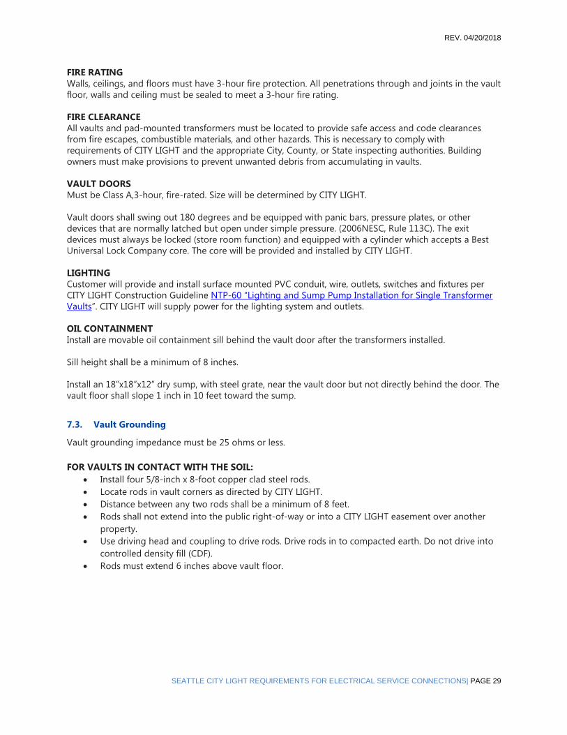
FIRE RATING
Walls, ceilings, and floors must have 3-hour fire protection. All penetrations through and joints in the vault
floor, walls and ceiling must be sealed to meet a 3-hour fire rating.
FIRE CLEARANCE
All vaults and pad-mounted transformers must be located to provide safe access and code clearances
from fire escapes, combustible materials, and other hazards. This is necessary to comply with
requirements of CITY LIGHT and the appropriate City, County, or State inspecting authorities. Building
owners must make provisions to prevent unwanted debris from accumulating in vaults.
VAULT DOORS
Must be Class A,3-hour, fire-rated. Size will be determined by CITY LIGHT.
Vault doors shall swing out 180 degrees and be equipped with panic bars, pressure plates, or other
devices that are normally latched but open under simple pressure. (2006NESC, Rule 113C). The exit
devices must always be locked (store room function) and equipped with a cylinder which accepts a Best
Universal Lock Company core. The core will be provided and installed by CITY LIGHT.
LIGHTING
Customer will provide and install surface mounted PVC conduit, wire, outlets, switches and fixtures per
CITY LIGHT Construction Guideline NTP-60 “Lighting and Sump Pump Installation for Single Transformer
Vaults”. CITY LIGHT will supply power for the lighting system and outlets.
OIL CONTAINMENT
Install are movable oil containment sill behind the vault door after the transformers installed.
Sill height shall be a minimum of 8 inches.
Install an 18”x18”x12” dry sump, with steel grate, near the vault door but not directly behind the door. The
vault floor shall slope 1 inch in 10 feet toward the sump.
7.3. Vault Grounding
Vault grounding impedance must be 25 ohms or less.
FOR VAULTS IN CONTACT WITH THE SOIL:
• Install four 5/8-inch x 8-foot copper clad steel rods.
• Locate rods in vault corners as directed by CITY LIGHT.
• Distance between any two rods shall be a minimum of 8 feet.
• Rods shall not extend into the public right-of-way or into a CITY LIGHT easement over another
property.
• Use driving head and coupling to drive rods. Drive rods in to compacted earth. Do not drive into
controlled density fill (CDF).
• Rods must extend 6 inches above vault floor.

REV. 04/20/2018
PAGE 30 | SEATTLE CITY LIGHT REQUIREMENTS FOR ELECTRICAL SERVICE CONNECTIONS
FOR VAULTS ON UPPER FLOORS:
• Four 5/8-inch x 8-foot copper clad steel ground rods shall be driven into compacted soil within
the property to be served. The rods shall be a minimum of 8 feet apart.
• Install a single bare-copper, soft-drawn, concentric-stranded cable between two of the four rods
and run the single cable into a corner wall of the transformer vault. The other two rods shall be
similarly connected with a second, single cable run into the opposite corner of the vault. Run the
ground cables into the vault no more than 18 inches above the floor. The cables shall penetrate
the vault walls through a protective sleeve. Extend at least 36 in of cable into the vault.
• The copper ground cables shall be connected to the ground rods with an exothermic weld
(CADWELD) or approved CITY LIGHT connector. The size of the copper ground cables shall be
adequate size to carry the available fault current.
• Between the rods and the vault, the vault ground cables shall remain 8 feet apart from any other
electrical ground cable, unless protected by non-metallic electrical conduit. The ground cables
shall be protected by non-metallic electrical conduit where not in contact with earth.
7.4. Vault Ventilation
Forced air ventilation is required. Fan capacity, in cubic feet per minute (CFM), will be based on
transformer size. Intake and exhaust vents shall be located in opposite corners.
Intake Vent Must Be:
• 18 inches above interior and exterior floor surfaces. Locate so air flows along the transformer
cooling fins.
• Installed with a damper to block air when vault temperature reaches 140 F. Cover with a screen or
louver to exclude rodents and birds.
Exhaust Vent Must Be:
• 6 inches below vault ceiling, or in ceiling.
• Located so air flows along the transformer cooling fins.
• 10 feet from building doors, windows, or flammable surfaces.
• 3-hour fire rated outside of vault, inside building.
• Installed without a damper.
• Covered at exterior opening with a screen or louver to exclude rodents and birds.
• Exhausted to the outside of the building.
Ventilation Fan Must Be:
• Mounted outside of the vault.
• Maintained by the customer.
• Powered from the customer’s service panel.

REV. 04/20/2018
SEATTLE CITY LIGHT REQUIREMENTS FOR ELECTRICAL SERVICE CONNECTIONS| PAGE 31
• Installed with a fan controller located outside of the vault which operates as follows:
— when vault temperature > 70° the fan turns on.
— when vault temperature > 140° the fan turns off and an alarm goes off.
THERMOSTAT AND VENTILATION CONTROLS
Transformer vaults shall have independent ventilation controls separate from the rest of the building. The
thermostat must be located inside the vault. After initial setting by the customer, the thermostat shall be
operated by CITY LIGHT personnel only. The building’s HVAC control system may monitor the vault
temperature and fan alarm signal but shall not control the vault fan or alarm.
VIBRATION AND NOISE LEVELS
The customer is responsible for isolating the transformer vault or pad. This will ensure sound and
vibration levels satisfy the applicable laws and ordinances of the Washington Administrative Code, the
City of Seattle or other applicable jurisdictions, including the customer’s own requirements.
UNRELATED SYSTEMS
No pipe or duct system unrelated to the electrical installation can enter or pass through a transformer
vault or pad enclosure. No customer-owned equipment for the customer’s use will be allowed in the vault
or pad enclosure, with the exception of air ducts for vault ventilation.
Fire sprinklers are not allowed in the vault.
HOIST SYSTEMS FOR HEAVY EQUIPMENT
If special hoisting or transporting facilities are necessary to remove, install, or maintain CITY LIGHT
equipment on customer property, the customer is responsible for moving the equipment. The customer
will transport the equipment to and from the point where CITY LIGHT can use its normal equipment-
handling methods. The customer will maintain the hoisting and transport facilities in a manner approved
by CITY LIGHT with advisory assistance from the Utility.
Elevators
Elevator service must be provided to any building level where a transformer vault is located.
7.5. NEC-sized Service Entrance Outside Network Areas
• The maximum size of NEC cable allowed to enter the vault is 750 kcmil.
• Depending on transformer size CITY LIGHT may terminate a maximum of six (6) sets of NEC-sized
cables directly on the transformer secondary terminals.
REV. 04/20/2018
PAGE 32 | SEATTLE CITY LIGHT REQUIREMENTS FOR ELECTRICAL SERVICE CONNECTIONS
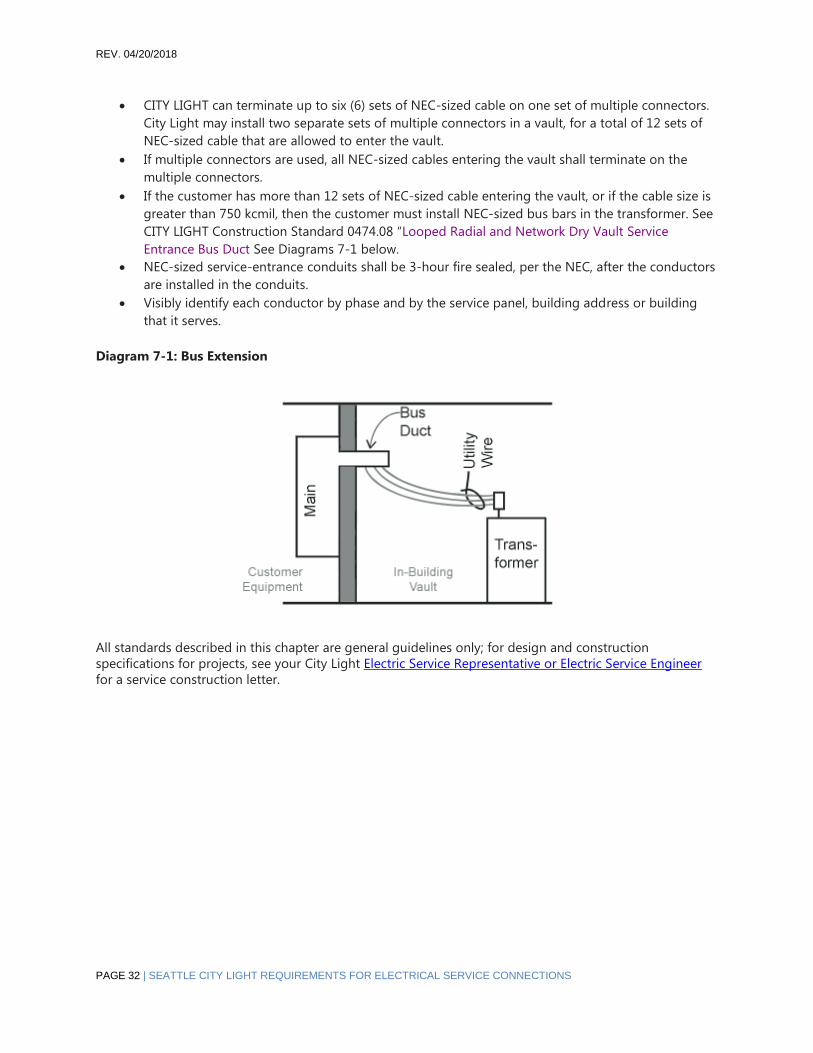
• CITY LIGHT can terminate up to six (6) sets of NEC-sized cable on one set of multiple connectors.
City Light may install two separate sets of multiple connectors in a vault, for a total of 12 sets of
NEC-sized cable that are allowed to enter the vault.
• If multiple connectors are used, all NEC-sized cables entering the vault shall terminate on the
multiple connectors.
• If the customer has more than 12 sets of NEC-sized cable entering the vault, or if the cable size is
greater than 750 kcmil, then the customer must install NEC-sized bus bars in the transformer. See
CITY LIGHT Construction Standard 0474.08 “Looped Radial and Network Dry Vault Service
Entrance Bus Duct See Diagrams 7-1 below.
• NEC-sized service-entrance conduits shall be 3-hour fire sealed, per the NEC, after the conductors
are installed in the conduits.
• Visibly identify each conductor by phase and by the service panel, building address or building
that it serves.
Diagram 7-1: Bus Extension
All standards described in this chapter are general guidelines only; for design and construction
specifications for projects, see your City Light Electric Service Representative or Electric Service Engineer
for a service construction letter.

REV. 04/20/2018
SEATTLE CITY LIGHT REQUIREMENTS FOR ELECTRICAL SERVICE CONNECTIONS| PAGE 33
8. Primary Services in Network Areas
City Light has four network service areas: Downtown Seattle, First Hill, University District, and the South
Lake Union area. Services to larger buildings, commercial office buildings and apartment buildings often
have larger electrical services which are served with primary voltages, meaning the owners provide space
and structures for CITY LIGHT’s transformers on their property. Vaults, pads and hand holes shall be
furnished by the customers on their property in accordance with CITY LIGHT requirements and
specifications, which will be provided in a service letter after reviewing the customer’s plans. This letter
and these specifications will be specific to each project. This chapter includes general guidelines, but the
customer must contact CITY LIGHT well in advance of vault design in order to receive the required design
specifications.
PRIMARY UNDERGROUND SERVICE IN NETWORK VAULTS: Where the aggregate service entrance
capacity exceeds 1,000 amperes at 208Y/120 volts or 600 amperes at 480Y/277 volts, the customer must
provide a vault or other suitable facilities on private property for Utility transformer(s) and associated
service equipment. Such vault or other facility for Utility transformer(s) must be located on the site being
served. The vault requirement for service ampacities over 600 amperes at 480Y/277 volts does not imply
that services at 480Y/277 volts are available in the 208Y/120-volt network areas at less than spot network
loading, as determined by City Light (CITY LIGHT).
ADVANCE NOTICE: It is essential that contractors notify CITY LIGHT well in advance of designing their
buildings as the requirements for a primary service may alter the building design. For instance, CITY LIGHT
may require space not only for the vault, but for a primary switchgear room as well.
INSPECTIONS The specific requirements given in the service letter will be part of City Light’s inspection of
the vaults during and after installation. The customer is also required to be aware of and satisfy all
applicable building codes for the City of Seattle as well as other cities and county jurisdictions in CITY
LIGHT’s service area.
8.1. Vault Construction in Network Areas
DIMENSIONS
The dimension of the transformer vault is determined by CITY LIGHT’s engineering group. The size of the
vault is contingent on:
• The size of transformer(s) to be installed. Transformer size is determined by the customer’s total
electrical load.
• The type of devices used for the secondary connection to the customer’s NEC-sized cables or bus
bars.
• The working clearance needed around the equipment.
DRY SPACE
Vault interior must remain dry. The customer must prevent water from entering the vault.
VAULT ACCESS
The customer must provide properly supported, unobstructed access from the right-of-way to the vault
for CITY LIGHT equipment-handling machinery. CITY LIGHT must be able to move electrical equipment in
REV. 04/20/2018
PAGE 34 | SEATTLE CITY LIGHT REQUIREMENTS FOR ELECTRICAL SERVICE CONNECTIONS
and out of the vault using CITY LIGHT equipment. In-building vaults shall not be located more than one
floor below the building’s exterior finished grade. The customer is also responsible for providing sufficient
building interior height, so CITY LIGHT can move tall transformers into and out of the vault with the
Utility’s machinery.
If CITY LIGHT cannot reach the vault with equipment to install the transformer, the customer may be
granted the option of moving the transformers. If this option is allowed, the customer must sign a City
Light “Equipment Transportation Agreement”.
An Equipment Transportation Agreement is a legal document in which the building owner(s) take sole
responsibility for moving the transformer(s) into and out of the transformer vault, to a mutually agreed
upon location from which CITY LIGHT is able to deliver or pick up the transformer(s) using our normal
transportation methods and equipment.
All Equipment Transportation Agreements will be recorded on the property title at the property owner’s
expense, as all future owners are obligated to the same terms and conditions of the agreement.
Any damage occurring to the transformer during transportation by the building owner(s) and any
additional expense incurred because of said damage shall be paid by the building owner(s).
A copy of the transportation agreement must be kept in the vault. The customer must provide and install
a weatherproof enclosure large enough to hold a paper copy of document. It shall be permanently
installed in a document enclosure on the vault wall beneath the light switch.
8.2. Structure Requirements
The vault walls shall be solid concrete up to eight feet high, minimum. The remainder of the walls shall be
solid concrete or concrete-filled masonry units.
Pre-tensioned or post-tensioned concrete: the location of the tension cables must be permanently
marked on the concrete’s surface.
Embedded insets may be required for the following:
• Seismic transformer anchoring in vault floor.
• Steel support channel in vault ceiling.
Equipment hatches are not allowed in the vault’s ceiling. Equipment may be lowered through an adjacent
shaft as outlined in the following City Light Construction standards:
0751.00 Construction Requirements, In-Building Transformer Vaults, Network and Looped Radial Systems
0751.60 Concurrent Customer Requirements, In-Building Transformer Vaults.
FIRE RATING
Walls, ceilings, and floors must have 3-hour fire protection. All penetrations through and joints in the vault
floor, walls and ceiling must be sealed to meet a 3-hour fire rating.

REV. 04/20/2018
SEATTLE CITY LIGHT REQUIREMENTS FOR ELECTRICAL SERVICE CONNECTIONS| PAGE 35
FIRE CLEARANCE
All vaults and pad-mounted transformers are to be located so as to provide safe access and code
clearances from fire escapes, combustible materials, and other hazards, in accordance with the
requirements of CITY LIGHT and the appropriate City, County, or State inspecting authorities. Building
owners must make provisions to prevent unwanted debris from accumulating in vaults.
VAULT DOORS
Must be Class A, 3-hour, fire-rated. Size will be determined by CITY LIGHT.
Vault doors shall swing out 180 degrees and be equipped with panic bars, pressure plates, or other
devices that are normally latched but open under simple pressure. (2006 NESC, Rule 113C). The exit
devices must always be locked (storeroom function) and equipped with a cylinder which accepts a Best
Universal Lock Company core.
The core will be provided and installed by CITY LIGHT.
LIGHTING
Vault lighting and outlets will be installed by CITY LIGHT at the time the electrical equipment is installed.
CITY LIGHT will supply power for the lighting system and power outlets.
8.3. Vault Construction Guidelines
For vault guidelines, please see City Light construction standards:
0751.00 Construction Requirements, In-Building Transformer Vaults, Network and Looped Radial Systems
Concurrent Customer Requirements, In-Building Transformer Vaults.
VIBRATION AND NOISE LEVELS
The customer is responsible for isolating the transformer vault or pad so that sound and vibration levels
satisfy the applicable laws and ordinances of the Washington Administrative Code, the City of Seattle or
other applicable jurisdictions, including the customer’s own requirements. Further, it is the customer’s
responsibility to mitigate any magnetic field effects from any customer owned sensitive equipment.
ELEVATORS
Elevator service must be provided to any building level where a transformer vault is located. NEC-sized
Service Entrance in Network Areas

REV. 04/20/2018
PAGE 36 | SEATTLE CITY LIGHT REQUIREMENTS FOR ELECTRICAL SERVICE CONNECTIONS
8.4. Secondary Underground Service in Network Areas
The aggregate service ampacity shall be limited to 1,000 amperes at 208Y/120 volts, or 600 amperes at
480Y/277 volts, depending on which is available.
Where the service entrance ampacity exceeds 200 amperes at 208Y/120 volts or 100 amperes at 480Y/277
volts, the service must be three-phase, four-wire, and the load must be balanced.
In buildings served from an underground network system, the customer must install the necessary
conduit to the Utility-designated point at the property line. CITY LIGHT will extend this conduit to CITY
LIGHT’s service handhole or vault and install service conductors to the point of service connection
designated by CITY LIGHT.
8.5. Residential Services to First Hill, South Lake Union and University District Networks
120/240 VOLT, SINGLE.PHASE SERVICE UP TO 225 AMPERES: The customer must provide a concrete pad
or space on the premises for our dry-type transformer. The customer must also install service conduit to a
point designated by CITY LIGHT. The transformer space and grounding must be approved by us and must
be in compliance with the City of Seattle electrical code. Where 120/240-volt service is available directly
from the network system, CITY LIGHT may not require a transformer pad or space.
208Y/120 VOLT, THREE.PHASE SERVICE, 100.1,000 AMPERES: The customer must supply a transformer
vault or space on the premises for our transformer(s), as well as service conduits to the property line as
specified by us. The transformer vault must be approved by CITY LIGHT and must be in compliance with
the CITY LIGHT electrical and building codes.).
480Y/277 VOLT, SINGLE.PHASE SERVICE TO 100 AMPERES: The customer must install service conduit to a
Utility designated point on the property line.
480Y/277 VOLT, THREE.PHASE SERVICE: The basic requirements for secondary underground network
service apply.
120/240 VOLT, SINGLE.PHASE SERVICE OVER 225 AMPERES: is not available.
REV. 04/20/2018
SEATTLE CITY LIGHT REQUIREMENTS FOR ELECTRICAL SERVICE CONNECTIONS| PAGE 37
9. Primary Underground: Transformer Pad
Construction
Transformer pads may be constructed outside of buildings in appropriate applications. The following are
general guidelines; the customer shall contact City Lightwell in advance of pad design in order to receive
the specific requirements for the project.
9.1. Transformer Pad Dimensions
CITY LIGHT will determine the pad size based on the customer’s total load and the type of devices used
for the secondary connection to the customer’s NEC-sized cables.
MINIMUM CLEARANCES:
FOR PADS NOT REQUIRING A FENCED ENCLOSURE, THE PAD MUST BE:
• 10 feet from any property line between private properties
• 10 feet from building doors or windows
• 10 feet from combustible structures
• 6 feet from noncombustible conductive (metal) structures
• 3 feet from noncombustible, conductive and combustible, nonconductive structures with a 3-hour
fire protection rating
• 3 feet from any property line adjacent to the public right-of-way
FOR PADS REQUIRING A FENCED ENCLOSURE, THE PAD MUST BE:
• 10 feet from any property line between private properties
• 10 feet from building doors or windows
• 10 feet from combustible structures
• 6 feet from noncombustible conductive (metal) structures
• 3 feet from noncombustible, nonconductive structures and combustible nonconductive structures
with a 3-hour fire protection rating
FOR THE FENCES OF THE ENCLOSED PADS, THE FENCE MUST BE:
• 6 feet from any property line
• 6 feet from noncombustible conductive (metal) structures
• 3 feet from noncombustible, nonconductive structures and combustible, nonconductive
structures with a 3-hour fire protection rating
9.2. Construction
• Prefabricated (from CITY LIGHT approved manufacturer) or cast in place concrete
• Conduit locations in the pad must meet the requirements given in the applicable CITY LIGHT Construction Guideline
• Foundations, footings, structures, tanks, piping, etc. are not allowed under the footprint of the pad ACCESS Provide unobstructed CITY LIGHT vehicular (truck) access to the pad at all times for the installation and the servicing of electrical equipment.

REV. 04/20/2018
PAGE 38 | SEATTLE CITY LIGHT REQUIREMENTS FOR ELECTRICAL SERVICE CONNECTIONS
GUARD POSTS
• To protect the pad-mounted transformer from vehicles, install 4-inch x 8-foot rigid steel posts, inserted to a depth of 4 feet and filled with concrete, after the transformer is installed.
• Locate guard posts a minimum of 6 feet in front of transformer doors. (Transformer doors will be located on the conduit-cut outside of precast pads.) Locate guard post a minimum of 3feet from the pad on the other three sides of the pad.
9.3. Oil Containment
PAVED APRON
• A paved apron that is impervious to spilled oil shall surround the concrete transformer pad. The
apron will extend a minimum of 3 feet from the pad edge.
• Gravel on bare soil for the apron area is not sufficient to meet the intent of the appropriate oil
spill regulations unless soils data is provided by and stamped by a professional engineer
registered in the State of Washington. This must certify that the soil is sufficiently impervious to
prevent escape of oil from the containment system before cleanup occurs.
OIL CONTAINMENT SYSTEM
An oil containment system includes: the concrete transformer pad, the paved apron, the surrounding curb,
dike, berm or other appropriate barrier, and any oil/water collection and separation system. The intent of
the oil containment system shall be to contain all spilled oil and oil-contaminated rainwater prior to
cleanup. Since this containment system is subject to rain and snow accumulation, provision is required for
handling water runoff.
The oil containment system shall conform to the current requirements of the Clean Water Act, Title 40 of
the Code of Federal Regulations, Part 112 (see 40 CFR 112.7(c) as amended. For convenience, pertinent
language from 40 CFR 112.7(c), current as of July 17, 2002 is quoted in part, as follows, or review the EPA
website: http://www.epa.gov/oilspill/.
“…The entire containment system…must be capable of containing oil…so that any discharge…will not
escape…before cleanup occurs. At a minimum, you must use one of the following prevention systems or
its equivalent:
• Dikes, berms, or retaining walls sufficiently impervious to contain oil
• Curbing
• Culverting, gutters, or other drainage systems
• Weirs, booms, or other barriers
• Retention ponds”
The criteria for regulations under 40 CFR 112 takes into consideration the potential for oil spill discharge
into navigable waters. In the CITY LIGHT service area, discharge to navigable waters would typically be of
concern if there is potential discharge to storm drain systems.
Design, construction, operation and maintenance of oil containment systems shall be the responsibility of
the property owner and includes:
• Appropriate provisions for oil and water run-off
• Separation of oil from water
• Periodic collection and proper disposal of oil and oil-contaminated water
REV. 04/20/2018
SEATTLE CITY LIGHT REQUIREMENTS FOR ELECTRICAL SERVICE CONNECTIONS| PAGE 39
SPILL PREVENTION, CONTROL &COUNTERMEASURE (SPCC) PLANS
For CITY LIGHT-owned transformers located on private property, preparation of SPCC plans in
conformance with 40 CFR 112 shall be the responsibility of the property owner.
9.4. Pad Grounding
Foundations, footings, structures, tanks, piping, etc. are not allowed under the footprint of the grounding
grid.
FOR PADS NOT REQUIRING A FENCED ENCLOSURE:
Install four 5/8-inch x 8-foot copper-clad steel ground rods, set at the pad’s corners, per the applicable
CITY LIGHT Construction Guideline 0652.03 “Transformer Pad Installation and Grounding 3Φ, 75-300KVA.
FOR PADS INSIDE FENCED ENCLOSURES:
• Install four 5/8-inch x 8-foot copper-clad steel ground rods, set at the pad’s corners, per the
applicable CITY LIGHT Construction Guideline 0652.03 “Transformer Pad Installation and
Grounding 3Φ, 75-300KVA.
• All conductive parts of the enclosure’s fence shall be tied to the pad’s ground grid.
• The fence gate shall be grounded to the fence post with a flexible braided copper strap.
• Install ground rods and ground cable around the perimeter of the metal fence, 18 inches away
from the fence, including out around the swing of the gate when opened, as instructed by CITY
LIGHT.
THE FENCE SHALL BE:
• 6 feet from conductive (metal) structures.
• 3 feet from nonconductive structures.
9.5. Service Termination Facility
FOR PADS NOT REQUIRING A FENCED ENCLOSURE:
• If the customer has more than four (4) sets of NEC-sized service entrance cables, the customer
may be required to install a service termination handhole for installation of multiple connectors.
CITY LIGHT will pull utility service cables from the transformer to the service termination handhole
and terminate the service on the multiple connectors.
• CITY LIGHT can terminate up to six (6) sets of NEC-sized cable on one set of multiple connectors.
CITY LIGHT may install two separate sets of multiple connectors in a large handhole, for a total of
12 sets of NEC-sized cable allowed to enter the handhole.
• If the customer has more than 12 sets of NEC-sized cable or if the cable size is greater than
750kcmil, then the customer must install NEC-sized secondary bus bars, spaced and drilled per
CITY LIGHT Construction Guideline 0474.08 “Looped Radial and Network Dry Vault Service
Entrance Bus Duct for Underground Primary Service” , in a service termination facility. CITY LIGHT
will pull utility service cables from the transformer to the service termination facility and terminate
the service on the bus bars.

REV. 04/20/2018
PAGE 40 | SEATTLE CITY LIGHT REQUIREMENTS FOR ELECTRICAL SERVICE CONNECTIONS
THE SERVICE TERMINATION FACILITY MAY BE:
• An in-building vault on an exterior wall at the same grade as the pad.
• A stand-alone, pad-mounted, cable-to-bus bar termination enclosure.
FOR PADS REQUIRING A FENCED ENCLOSURE:
If the customer has more than six (6) sets of NEC-sized service entrance cables or the cable size is greater
than 750 kcmil, then the customer must install NEC-sized secondary bus bars. These will be spaced and
drilled per CITY LIGHT Construction Guideline 0474.08 “Looped Radial and Network Dry Vault Service
Entrance Bus Duct for Underground Primary Service” in a stand-alone, pad-mounted, cable-to-bus-bar
termination enclosure located next to the fenced enclosure. The bus bars must extend over the fence into
the enclosure at a height given in the above construction guideline.

REV. 04/20/2018
SEATTLE CITY LIGHT REQUIREMENTS FOR ELECTRICAL SERVICE CONNECTIONS| PAGE 41
10. Maintenance of Conductors and Division of
Responsibility
This chapter distinguishes City Light’s responsibility for equipment and maintenance from that of the
customer. The customer is responsible for:
• All masts, brackets, conduits, and other service entrance equipment
• Conduit and trenching to CITY LIGHT’s designated point of connection to the system
• All equipment on the load side of the meter
• Any other equipment for which the customer is assigned responsibility in written agreements
between us
10.1. Primary Underground Service
DIVISION OF RESPONSIBILITY
For each installation of primary underground service, CITY LIGHT will establish the point where CITY
LIGHT’s responsibility ends, and the customer’s responsibility begins. All facilities on the customer’s side
of this point will be furnished, installed, operated, and maintained by the customer unless other
arrangements are agreed to in writing. The customer is also responsible for conduit and trenching to CITY
LIGHT’s designated point of connection to the system.
EXTENSIONS OF PRIMARY UNDERGROUND
ADDITIONAL PADS OR VAULTS—Any extensions of primary service conductors to additional transformer
vaults or pads will be made by CITY LIGHT and will remain our property. The customer, however, must
furnish and install the primary conduit, vault or pad as required and must pay the cost of the extension.
EXTENSIONS BEYOND A PRIMARY METER
Extensions beyond a primary meter are the customer’s responsibility.
TRANSFORMERS
Transformers connected to our primary distribution system will be furnished, installed, and maintained by
CITY LIGHT. The customer will be responsible for removing any transformer that CITY LIGHT determines it
cannot remove. Transformers on the customer’s side of the meter are the customer’s responsibility to
furnish, install and maintain unless otherwise agreed to in writing.
10.2. Poles
CITY LIGHT will maintain all their own installed poles and anchors. Customer-owned poles installed by
CITY LIGHT will be maintained by CITY LIGHT at the customer’s expense.
10.3. Metering Equipment
CITY LIGHT will maintain all meters, instrument transformers, and related equipment. See also
Chapter 11, “Metering.”

REV. 04/20/2018
PAGE 42 | SEATTLE CITY LIGHT REQUIREMENTS FOR ELECTRICAL SERVICE CONNECTIONS
10.4. Maintenance of Underground Conductors
Underground conductors will be maintained by CITY LIGHT in the following manner:
SERVICES IN CONDUIT
CITY LIGHT will provide new service wire if the existing conductors fail. CITY LIGHT’s crew will pull out the
old wire and install new service wire provided they are able to remove the old conductors. If the conduit
has been damaged or rusted, the wires may not be able to be removed. The conduit housing the service is
the customer’s property and responsibility. If the wires cannot be pulled from the conduit, the customer
will be responsible for trenching and installing new conduit from the meter base to a point designated by
CITY LIGHT. Then CITY LIGHT will furnish and install the new service wire.
SERVICES WITHOUT CONDUIT
In situations where the service wire is buried in the ground without conduit and the service fails, CITY
LIGHT will locate the fault, excavate, repair the cable, and backfill the excavated material. The customer is
responsible for all surface restoration, e.g., grass, shrubbery, concrete.
This procedure applies only if there is a single fault or break in the run of wire. Often when direct burial
conductors age they will fail in more than one location. This indicates the entire service run needs to be
replaced. If the crew has exposed and repaired one fault, and the service has more faulted are as, the
customer will be required to trench and provide a conduit run from the meter base to a point designated
by CITY LIGHT. Then CITY LIGHT will furnish and install the service conductors in the newly installed
conduit.
CHARGES FOR MAINTENANCE
There will be no charges for installing underground service conductors on existing services for
replacement due to failure. The exceptions are as follows:
• The service was not installed by CITY LIGHT but by a private contractor within five (5) years of the
date of the failure. In this case the wire is to be replaced by the installer according the CITY LIGHT
specifications.
• The conductors have faulted as a result of some action on the customer’s part; e.g. wire damaged
by digging; post or retaining wall installation damaging conduit and wire; improper backfill. If the
cause of the fault is related to such or other actions, the customer will be charged for the repair
work.
TEMPORARY RESTORATION OF SERVICE
CITY LIGHT may restore service on a temporary basis until the customer completes the necessary work, so
CITY LIGHT can replace the service conductors. If CITY LIGHT is unable to install an electrical meter during
this time, the customer will receive an estimated bill for the period their electrical usage is unmetered.
The temporary service will be granted for a maximum of two (2) weeks. The connection will not be
maintained beyond this period.

REV. 04/20/2018
SEATTLE CITY LIGHT REQUIREMENTS FOR ELECTRICAL SERVICE CONNECTIONS| PAGE 43
11. Metering
Electricity meters are required on the customer’s premises for all City Light (City Light) electrical services
so the Utility can accurately determine customer usage for accurate billing and for maintaining
appropriate distribution to our customers.
City Light provides and installs all electricity meters into customer‐installed meter bases. This chapter will
describe the requirements for metering equipment and installations.
City Light’s Technical Metering Unit will provide the customer with specific information on metering
requirements for individual projects after they have reviewed plans submitted by the customer. Prints or
drawings of the metering equipment shall be submitted and approved by City Light prior to manufacture
when the equipment is to be installed in switchgear. The drawings need to show the sequence of
compartments, dimensions of the gear and manufacturer information. Drawings shall also be submitted
and approved for customer‐designed pedestals or other structures on which the customer is proposing to
mount metering or service entrance equipment. All drawings or prints submitted to City Light must be
engineering or architectural grade.
11.1. Meter Sockets: Construction Guidelines
All services shall be metered in accordance with the Electrical Utility Service Equipment Requirements
Committee (EUSERC) Standards. Refer to http://www.seattle.gov/light/electricservice/default.asp to
contact an Electric Service Representative or Electric Service Engineer if you have any questions regarding
EUSERC standards.
While City Light provides and installs the meter, the customer is responsible for providing and installing
the meter socket and current transformer equipment, if applicable. All meter sockets shall meet ANSI C12
and UL414 Standards for Meter Sockets. All current transformer enclosures (CT cans) and metering
switchgear must meet EUSERC and City Light standards.
It is important to refer to DU13-4/NMT-30 Meter Base Arrangements for the correct meter socket for your
application in order to avoid delays to receiving service.
Commercial services require block by‐pass or safety sockets. Safety sockets are required where the service
voltage is 277V to neutral or 480V phase to phase.
Residential services do not require block by‐pass sockets; however, they are strongly recommended.
Exception: Residential services rated at 400 amps and served with a Class 320 self‐contained meter will
require a block by‐pass.
City Light does not allow automatic, lever type, or slide‐link socket bypass devices. City Light does not
allow ringless meter sockets/bases of any type.
Only metering taps are allowed in meter sockets. Examples of metering taps are the 5th and 7th terminal
connections to the neutral and a 5th terminal connection to the unmetered leg as in existing three phase,
three‐wire Delta services.
5th terminals shall not be installed in 120/240V sockets.

REV. 04/20/2018
PAGE 44 | SEATTLE CITY LIGHT REQUIREMENTS FOR ELECTRICAL SERVICE CONNECTIONS
The line side conductors are connected to the top terminals of the meter socket. The load side conductors
are connected to the bottom terminals.
Exception: Production meter sockets shall be wired with the line side conductors connected to the bottom
terminals, and the conductors from the generation source on the top terminals.
Unused threaded or knockout openings must be closed with an approved plug locked in place from the
inside. Metering equipment enclosures shall be weatherproof if they are located outside.
Meter rings will be provided by City Light.
11.2. Temporary Totalization Metering
At City Light's discretion, Temporary Totalized Metering may be utilized to capture a customer’s total
consumption for billing purposes. This temporary metering will generally apply to a project during initial
construction but may be used when a customer is altering or upgrading their service entrance equipment.
All required equipment for this metering will be the sole responsibility of City Light, and all metered
consumption will be billed in accordance with the appropriate rate schedule.
If a customer completes a Temporary Totalized Metering Agreement Form with the assistance of the
appropriate Electric Service Representative or Electric Service Engineer, they will be allowed to shunt self‐
contained meter sockets prior to installation of the permanent metering.
Once the facility is ready for permanent meter installation, it is the responsibility of the property owner to
contact City Light, and ensure that all metering facilities are prepared according to City Light’s
specifications, including the Multi‐Unit Pre‐metering Checklist. Failure to meet these requirements may
result in fines, additional trip charges, and installation delays.
Communication Provisions for Large Metered Loads are in no way altered or impacted by the
requirements of the Temporary Totalized Meter specifications.
11.3. Metering Voltages
All services shall be metered at the service voltage. The exception would be 480Y/277 volt three‐phase
services transformed to 120/208 volts or 120/240 volts for distribution in multi‐unit buildings.
All high voltage services, 601 volts and above, shall be metered at the service voltage in accordance with
the Electric Utility Service Equipment Requirements (EUSERC) standards and City Light Construction
Guidelines.
Where voltages are over 600 volts, contact the Electric Service Engineer for high voltage metering
requirements.
11.4. Service Entrance Conductors for Metered Loads
• Unmetered service conductors and metered load conductors shall not be run in the
same conduit, raceway, or wiring gutter.

REV. 04/20/2018
SEATTLE CITY LIGHT REQUIREMENTS FOR ELECTRICAL SERVICE CONNECTIONS| PAGE 45
• Metering equipment and enclosures containing unmetered service conductors, wire
troughs, and busing shall be sealable and lockable as determined by City Light.
• Metered load conductors shall not pass through sealable sections, including current
transformer enclosures.
• Service conductors shall be continuous from the service connection point to the meter
socket or current transformer enclosure, or in a main disconnect for group installations.
The conductors shall not pass through any junction box or “T” condulets. This does not
prohibit the use of buses or wire troughs on the line side of multi‐meter installations if
the enclosures are locked and sealed.
11.5. Conductor Connections
For Aluminum: An oxide inhibitor is used for all aluminum conductors and connections. The meter socket
shall have lugs approved for aluminum.
For Copper: When copper is used as conductor, meter terminals, and/or socket jaws, an oxide inhibitor
must not be used.
11.6. Service Entrance Equipment Sequencing
For Single Meters Self-Contained:
• The sequence of service equipment with self‐contained metering shall first be meter socket and
next the fused disconnect/circuit breaker. A switch cannot precede the meter except in certain
multi‐unit installations (described below).
• Pedestal metering shall not contain the customer’s main disconnect.
For Multi-Unit Installations
• A main disconnect may be installed ahead of the meters in multi‐unit installations involving more
than six individual sockets provided that all equipment ahead of the meters has sealing
provisions.
• In multiple meter socket installations, which have a switch or breaker ahead of the meters, the
breaker shall be the common trip type i.e., must open or close all ungrounded conductors
simultaneously. The breaker must be constructed to prevent being changed to a non‐trip type.
11.7. Master Metering
City Light shall not supply electricity for any new service to a duplex or multiple dwelling building for the
purpose of master metering the energy usage of the dwelling units, a central space heating system, or a
central domestic water heating system. City Light will not supply electricity for any upgraded service to an
existing duplex or multi‐unit building for the purpose of master metering new central or individual space
heating systems.
Master metering is required for boat moorages but prohibited for houseboats.

REV. 04/20/2018
PAGE 46 | SEATTLE CITY LIGHT REQUIREMENTS FOR ELECTRICAL SERVICE CONNECTIONS
11.8. Special Metering Requirements for Multi-Unit Buildings
• Prior to meter installation all meter sockets must be identified with permanent labeling by final
space or unit number, letter designation, and/or street address. Meter bases shall have engraved
phenolic nameplates installed on the cover of the meter socket.
• NOTE: Felt‐tip pens and label maker tape are not considered permanent marking.
• Permanent numbering of the separately metered spaces or units is required. If it is not practical
before meter installation, the customer shall provide temporary identification at the main
entrance of the space for the purpose of performing space checks.
• Please see Appendix 7: “Contractor’s Pre‐Installation Checklist Multi‐Unit Metering” for more
information.
• All multi‐unit buildings shall have at least one meter for each unit. Where common load exists, an
additional house meter is required.
• The sockets in meter banks shall be so arranged that the minimum vertical distance between
socket centers is 9 inches and the minimum horizontal distance is 8 inches. Additional clearance
requirements are described in Appendix 5 – Clearances for Residential Multiple Metering
Installations.
• City Light conducted space checks are required for all new and rewired multi‐unit buildings to
verify socket‐to‐unit panel wiring.
• All auxiliary dwelling units without separate metering, and/or units found to have mixed or
common loads will be billed in the owner’s name.
• After the initial service installation, all additional space checks, address changes, and mixed‐ load
checks will be charged to the owner or person making the request.
• Load determination shall be based upon the greatest aggregate nameplate ratings of each fused
disconnect or circuit breaker.
11.9. Provisions for Automated Metering
Requirements for Single and Multiple Metering Equipment rooms are described below.
11.10. Multiple Metering Equipment Room
• Where multiple equipment rooms are vertically stacked, a 2‐inch Schedule 40 PVC conduit
pathway connecting all of the equipment rooms shall be provided for the Advanced Metering
antenna cable. Lateral meter rooms should also be tied into the vertical distribution stack whenever possible.
o The conduit shall have a maximum of 360 degrees in total bends.
o A 1/8‐inch minimum nylon zip tie pull string is to be provided in the conduit.

REV. 04/20/2018
SEATTLE CITY LIGHT REQUIREMENTS FOR ELECTRICAL SERVICE CONNECTIONS| PAGE 47
o All connection cables for Advanced Meters shall be provided by CITY LIGHT and installed
by the customer. CITY LIGHT will make all connections.
o Cables shall be in contiguous runs, without splices, unless otherwise approved by CITY
LIGHT.
• In either the top most or bottom most meter room (including sub-grade meter rooms), provide a
2‐inch Schedule 40 PVC conduit to a NEMA 3R enclosure (enclosure shall be at least 8 inches x 8
inches x 6 inches) mounted on exterior of the building. The conduit shall have a maximum of 360
degrees in total bends and no more than 100 feet of total length.
o A 1/8‐inch minimum nylon zip tie pull string is to be provided in the conduit.
o All connection cables for Advanced Meters shall be provided by CITY LIGHT and installed
by the customer. CITY LIGHT will make all connections.
o NEMA 3R enclosure shall be mounted in a location that is approved by CITY LIGHT and is
safe to access. NEMA 3R enclosure shall be mounted between 14 and 20 feet above
ground level, unless roof top access is available and can be accessed without
hazard/restraint.
o Cables shall be in contiguous runs, without splices, unless otherwise approved by CITY
LIGHT.
• In the electrical room with conduit to the exterior of building, the customer must provide a 2-foot
x 2-foot x 3/4-inch plywood mounting board with dedicated duplex receptacle. 1. Plywood shall
be mounted on wall adjacent to meter (or meter bank) less than 20 lineal feet from closest meter.
o The NEMA location
o Bottom edge of plywood mounting board shall be between 4 and 6 feet above floor level.
o A dedicated 120 Volt, 15 Amp Duplex power receptacle shall be below the plywood
mounting board.
11.11. Metering Equipment Location
• Single meter sockets shall be installed in an accessible location outside the building. Multiple
socket installations may be located inside the building.
• City Light may post a Utility logo on the outside of meter room doors.
• City Light shall inspect and approve the customer’s choice of location for meter sockets and
metering equipment prior to beginning equipment installation. The location must be readily
accessible without risk of bodily harm to City Light employees and free from vibration, corrosive
atmosphere, and extreme temperatures.
• Inside meter locations shall have sufficient lighting to read meters and maintain equipment.
• The area around and access to all City Light equipment shall be free from vegetation.
• Meter rooms shall be for the sole purpose of electrical switchgear and metering equipment.
Under no circumstances shall gasoline, diesel fuel, propane, paints, or any other noxious or
hazardous materials be stored in a meter room.

REV. 04/20/2018
PAGE 48 | SEATTLE CITY LIGHT REQUIREMENTS FOR ELECTRICAL SERVICE CONNECTIONS
• Metering equipment shall not be installed over stairs, stairwells, steps, or public walkways. If
mounted on a balcony or platform, a fixed stairway to the area is required and must be
maintained for the duration that the service exists. Ship’s ladders are not allowed. For balcony
or platform installations the structure must be professionally engineered. The structure must meet
all Washington Administrative Code (WAC) requirements. CITY LIGHT requires meshing be
installed on the railing as an additional safe guard with the opening not to exceed ½ inch.
• Meter locations must not be under or over any structure which might be enclosed or removed in
the future, such as a porch, deck, carport, or stairway.
• All current transformer enclosures will be installed in an accessible location outside the building
or in an approved electric meter room. For residential services the current transformer enclosures
shall be outdoors and accessible during normal Utility working hours.
• Electric meter bases shall be installed a minimum of three feet from the closest point of a natural
gas meter installation. The natural gas meter installation shall not be within the required working
space as specified in “Access to Metering Equipment – paragraph f.”
11.12. Meter Height
• The meter height is measured from grade or the floor to the center of the meter.
• The preferred meter height for single meter sockets is 5 feet.
• All meter sockets shall be mounted plumb and be securely fastened.
Table 11-1
Meter Height Requirements
Type of Installation Minimum Height Maximum Height
Single Meter Socket 4 feet 6 feet
Multi-Unit Installations 2 feet 6 feet
11.13. Access to Metering Equipment
City Light reserves the right to access the customer’s premises during normal business hours (Monday
through Friday, 8 AM to 4 PM) for meter reading, testing, installation, removal, inspection, and/or
maintenance of City Light’s equipment.
• Access shall not be blocked by either permanent or portable materials.
• Any fenced/enclosed areas and/or metering cabinets/enclosures shall be made accessible with a
City Light provided key box at owner’s expense. This lock box will be co‐located with the Fire
Department’s Lock Box (where applicable). The customer shall provide keys and/or key cards.
• All metering equipment covers shall be readily accessible They may not be plastered, caulked, or
built in, in any way, so as to impede the opening of the meter cover or metering equipment
covers including current transformer enclosure covers or doors.

REV. 04/20/2018
SEATTLE CITY LIGHT REQUIREMENTS FOR ELECTRICAL SERVICE CONNECTIONS| PAGE 49
• All metering equipment doors shall open a minimum of 90° from the front of the enclosures.
Outdoor equipment enclosure doors must have a hold open device.
• The width of the working space shall permit access to the metering equipment and in no case
shall be less than 3 feet. The height of the working space shall be in no case less than 7 feet, 1
inch from grade, platform or floor. The working space shall extend at least 3 feet out from the
face of the meter. A level working space no less than 3 feet by 3 feet shall be provided and
maintained in front of all meter equipment with no obstructive vegetation.
• Single meter sockets shall be installed with a preferred 18-inch clearance from the center of the
socket to the nearest side wall or obstruction and in no case shall be less than 10 inches.
11.14. Protection of Metering Equipment
• Where damage of metering equipment has or is likely to occur from vandalism, vehicles or other
causes, City Light may require the customer to install protective devices such as bollards, barriers,
or enclosures at the customer’s expense.
• Metering equipment enclosures installed in outside locations shall be weatherproof.
• Pedestal metering equipment shall be sturdy enough for reasonable installation or removal of a
meter without damage to the pedestal.
• Indoor spaces housing metering equipment shall have the ambient air temperature maintained
below 30 degrees C (86F). The customer is responsible for cost of maintenance, repairs and
replacement of meter equipment resulting from ambient temperature.
11.15. Ownership of Metering Equipment
City Light installs and maintains meters, instruments, transformers and associated equipment which are on
the City Light side of the meter. The Utility has ownership of this equipment. The customer’s equipment
includes: meter sockets, enclosures, landing pads, lugs, conduit, and conductors. These are installed and
maintained by the customer who is the owner of this equipment.
City Light shall determine the specific metering equipment requirements after reviewing customer plans
and or drawings.
11.16. Current Transformer-Rated Metering
Current transformers and/or voltage transformers are required on all services that exceed 225 amps. The
two exceptions to this case are residential services with 400 amps services that use class 320 metering and
remote metering with services under 225 amps.
All transformer‐rated meter sockets shall have test switch provisions.

REV. 04/20/2018
PAGE 50 | SEATTLE CITY LIGHT REQUIREMENTS FOR ELECTRICAL SERVICE CONNECTIONS
11.17. Current Transformer Landing Pads and Enclosures
Current transformer enclosures shall contain only service conductors, metering equipment, and meter
conductors. They shall not be used as a junction box, gutter, or raceway for the purpose of making taps.
Exception: Taps shall be allowed on the load side of the customer’s landing pads to accommodate
emergency services, fire pumps, and/or elevator ventilation systems as allowed by local/national
fire codes.
• All services rated at 800 amps or less that use current transformer landing pads having
mechanical lug provisions for termination of line and load conductors. Landing pads shall be
centrally mounted in the current transformer enclosure and the conductors will enter and leave
near the corners. NOTE: If terminations cannot be made in accordance with manufacturer
requirements and/or equipment listing, a bus gutter will be required to accommodate additional
taps.
• All services rated over 800 amps shall be installed in manufactured metering switchgear per
EUSERC specifications.
The minimum size of current transformer enclosures shall be as follows:
o Single phase 400 amps or under: 24 inches wide x 48 inches high x 11 inches deep.
o Single phase over 400 amps: 36 inches wide x 48 inches high x 11 inches deep.
o Three phase: 36 inches wide x 48 inches high x 11 inches deep.
o NOTE: Larger current transformer enclosures may be necessary depending on the
National Electric Code (NEC) requirements for conductor bends.
• All landing pads shall be of heavy‐duty type with minimum (AIC) fault duty rating of 50,000 amps
RMS symmetrical. They shall be UL labeled and built to EUSERC standards.
• The cover of the current transformer enclosure or switchgear shall be side‐hinged and have
provisions for locks and seals. Hinges must be built so that they cannot be disassembled from the
outside of the enclosure. All metering equipment doors shall open a minimum of 90˚ from the
front of the enclosures.
• The top of the current transformer enclosure shall not be higher than 7 feet and the bottom shall
not be lower than 6 inches from the finished grade or floor.
• Connection to the grounded service conductor (neutral) shall not be used to bond current
transformer enclosures. Bonding shall be derived from the service main grounding point.
11.18. Secondary Wiring for Transformer-Rated Meters
The customer shall provide a 1-inch minimum conduit between the current transformer enclosure and the
meter socket. A maximum of 360 degrees of bends is allowable. For metering runs over 75 feet a 1‐1/4-
inch minimum conduit is required.
• Junction boxes and condulets are not allowed in conduit runs for secondary metering conductors.
• The customer shall provide metering secondary conductors, leaving 8 feet of wire in the current
transformer enclosure and 2 feet of wire in the socket enclosure.

REV. 04/20/2018
SEATTLE CITY LIGHT REQUIREMENTS FOR ELECTRICAL SERVICE CONNECTIONS| PAGE 51
Exception: City Light will provide the metering secondary conductors when the socket is within ten
(10) feet of the current transformer enclosure.
• All secondary conduit runs over 75 feet shall have prior approval by City Light’s Technical
Metering Unit. Conduit runs beyond 250 feet are not permitted.
• The conductor colors for CT metering secondary runs are as follows:
Single Phase: 1 black, 1 red, #12 solid conductor (voltage)
1 black, 1 red and 1 white #10 solid conductor (current)
1 green #12 solid conductor (bonding)
Three Phase: 1 black. 1 red, 1 blue, 1 white, #12 solid conductor (voltage)
1 black, 1 red, 1 blue, 1 white #10 solid conductor (current)
1 green #12 solid conductor (bonding)
For secondary runs over 75 feet the current conductors need to be sized as follows:
• #8 stranded conductors for current circuits from 75’ to 150’.
• #6 stranded conductors for current circuits from 150’ to 250’.
11.19. Metering on Switchboards
• Multiple self‐contained metering: the clear space around each meter socket will not be less than
one inch at the top and the sides, and not less than 2 inches at the bottom.
• All side clearances will meet City Light standards.
• Metering section panels on switchgear will open a full 90° to the switchgear.
• Customer equipment that requires servicing shall not be installed in current transformer metering
compartments. For further information contact the ESR or ESE.
• Permanent switchboard metered services shall not have the electric meter located on the
switchboard door adjacent to the current transformer compartment. The meter shall be located in
a remote single meter base with a test switch provision on the nearest possible wall.
NOTE: Permanent engraved phenolic unit or equipment designation labeling is required at both the meter
base and the switchboard.
11.20. Net Metering
City Light allows net metering on approved customer generation installations of up to 100kw in most
areas of the service territory. Installations over 25kw will require City Light engineering review. Net
Metering is not allowed in network service areas. However, customer generation is allowed in network
areas if it meets certain requirements, chief among which is that the installation be precluded from
feeding back onto the network grid. For more information, see Chapter 14 – Customer Generation.

REV. 04/20/2018
PAGE 52 | SEATTLE CITY LIGHT REQUIREMENTS FOR ELECTRICAL SERVICE CONNECTIONS
11.21. Communications Provisions for Large Metered Loads
Where totalized metering is permitted, the customer shall install the totalizing circuitry. Meter totalizing
shall meet the Utility’s criteria and be approved by City Light before metering equipment will be installed.
The customer shall provide and maintain a phone line that meets City Light requirements.
New or enlarged commercial/industrial services served by a single meter with loads that are expected to
reach 1 megawatt or more, or that will be totalized, are required to have a phone line or communication
line at the point of metering. The customer shall own, install, and maintain the phone/communication line.
For all internal meter rooms, the customer shall install Schedule 40, 1½‐inch conduit from the interior of
the room to the exterior of the building for automated meter reading. The conduit shall extend 4 inches at
each end and be capped.
Revision Date Revision
April 2, 2013 Added Section “g” to “Current Transformer
Landing Pad Enclosures” – restriction on bonding
to the neutral.
April 10, 2013 Clarified net metering provisions
December 20, 2013 Further clarified language on Net Metering, added
provisions for Temporary Totalized Metering on
certain loads.
October 20, 2015 Maximum meter height reduced to 6 feet. Electric
meter bases shall be installed a minimum of three
feet from the closest point of a natural gas meter
installation. All permanent switchboard metered
services shall have remote single socket
enclosures. Engraved phenolic labels required on
all multi‐unit building sockets prior to meter
installation. An 18-inch clearance from
obstructions to the center of single meter sockets.
Removal of requirement for bus gutters or
common mainline switch on 800 amps or less
transformer rated services with provision that
landing pads with mechanical lugs are used within
manufacturer specifications. Single phase current
transformer enclosures over 400 amps to be 36
inches wide.
Drawings for metering in switchgear shall be
submitted prior to construction.
January 2016 Integration of Advanced Metering requirements
for meter rooms.
March 2016
Added prohibition on ringless meter
bases/sockets

REV. 04/20/2018
SEATTLE CITY LIGHT REQUIREMENTS FOR ELECTRICAL SERVICE CONNECTIONS| PAGE 53
March 2016
Removed Advanced Metering requirements for
meter rooms. See construction letter for
information after plan submittal.
September 2016
Revised Advanced Metering requirements for
meter rooms.
February 2018
Revised requirements for balcony and platform
installations.

REV. 04/20/2018
PAGE 54 | SEATTLE CITY LIGHT REQUIREMENTS FOR ELECTRICAL SERVICE CONNECTIONS
12. Motors and Special Loads
Certain of City Light’s large commercial or industrial customers may require motors or special voltages for
their businesses. This chapter identifies CITY LIGHT’s requirements related to motors and special loads
and voltages.
The Utility requires detailed information about new installations of motor load. The specific information
required is included in this chapter as well as the Motor Load Detail Worksheet This information should be
provided to City Light well ahead of the installation. Manufacture of special equipment and major
construction may require up to 18 months advance notice.
The customer is responsible to provide suitable protective devices on all motor installations, including ad‐
equate protection against single phasing on polyphase motors.
12.1. Motor-Starting Limitations
The customer’s use of electricity must not interfere with the quality of their own service and must not
interfere with the quality of service to other customers. If any motor and associated device(s) cause
interference with its owner’s or another customer’s electrical service, the owner of the motor/device is
responsible for taking corrective action. Conforming to the requirements in the sections below does not
assure that interference problems will not occur.
12.2. Starting Limitations on Single-Phase Motors
One‐half horsepower or larger motors on recurrent starting with more than one start per hour, such as
those operating water pumps or furnace blowers, must be served at not less than 240 volts (208 volts in
the Network system). Single‐phase motors must not exceed the maximum locked rotor currents listed in
Tables 12‐1 and 12‐2, unless approved in writing by CITY LIGHT.
Table 12-1
Single-Phase Motor Maximum Allowable Locked Rotor Currents
Rated Size
5 horsepower
At 208 volts (Network only)
149 amperes
At 240 volts
129 amperes
Table 12-2
Single-Phase Hermetic Refrigerant Motor Compressor Maximum Allowable Locked Rotor
Currents (from NEMA standards)
Unit Size (in tons)
2
2 ½
3
3 ½
4
4 ½
5
Motor Size (Horsepower)
2 hp
2 ½ hp
3 hp
3 ½ hp
4 hp
4 ½ hp
5 hp
At 208 volts
80 amps
100 amps
120 amps
140 amps
160 amps
180 amps
200 amps
At 240 volts
69 amps
87 amps
104 amps
121 amps
138 amps
156 amps
173 amps
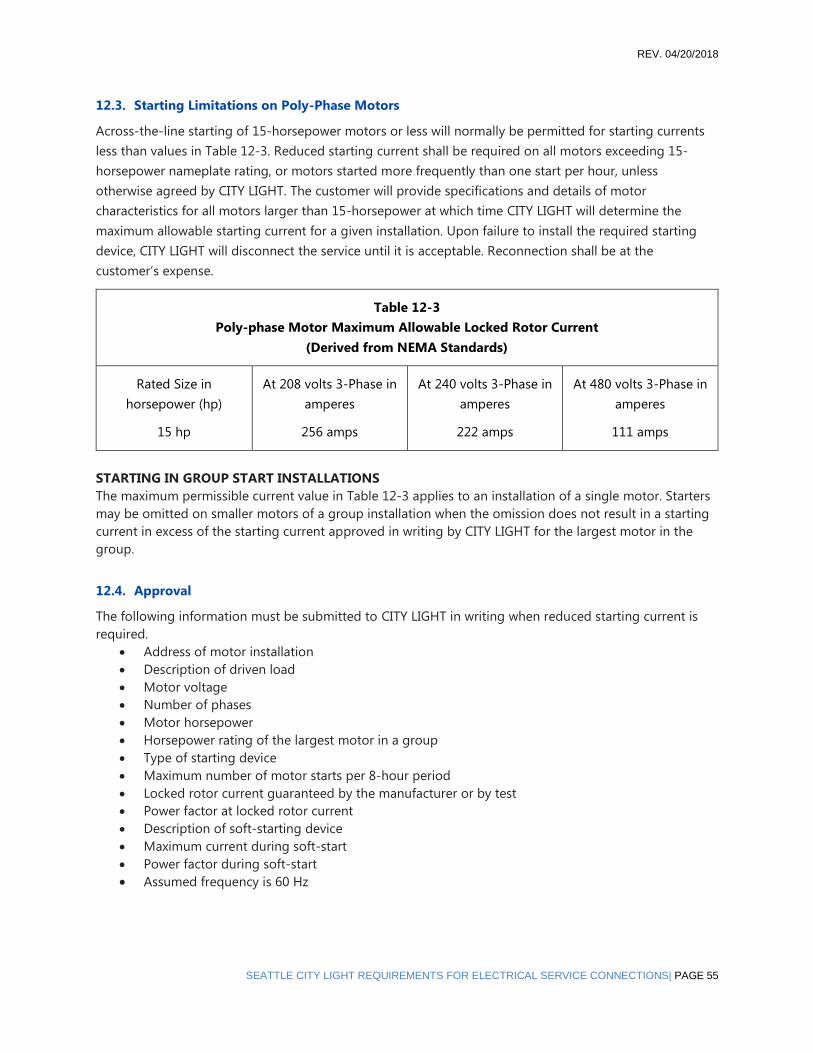
REV. 04/20/2018
SEATTLE CITY LIGHT REQUIREMENTS FOR ELECTRICAL SERVICE CONNECTIONS| PAGE 55
12.3. Starting Limitations on Poly-Phase Motors
Across‐the‐line starting of 15‐horsepower motors or less will normally be permitted for starting currents
less than values in Table 12‐3. Reduced starting current shall be required on all motors exceeding 15‐
horsepower nameplate rating, or motors started more frequently than one start per hour, unless
otherwise agreed by CITY LIGHT. The customer will provide specifications and details of motor
characteristics for all motors larger than 15-horsepower at which time CITY LIGHT will determine the
maximum allowable starting current for a given installation. Upon failure to install the required starting
device, CITY LIGHT will disconnect the service until it is acceptable. Reconnection shall be at the
customer’s expense.
Table 12-3
Poly-phase Motor Maximum Allowable Locked Rotor Current
(Derived from NEMA Standards)
Rated Size in
horsepower (hp)
15 hp
At 208 volts 3-Phase in
amperes
256 amps
At 240 volts 3-Phase in
amperes
222 amps
At 480 volts 3-Phase in
amperes
111 amps
STARTING IN GROUP START INSTALLATIONS
The maximum permissible current value in Table 12‐3 applies to an installation of a single motor. Starters
may be omitted on smaller motors of a group installation when the omission does not result in a starting
current in excess of the starting current approved in writing by CITY LIGHT for the largest motor in the
group.
12.4. Approval
The following information must be submitted to CITY LIGHT in writing when reduced starting current is
required.
• Address of motor installation
• Description of driven load
• Motor voltage
• Number of phases
• Motor horsepower
• Horsepower rating of the largest motor in a group
• Type of starting device
• Maximum number of motor starts per 8‐hour period
• Locked rotor current guaranteed by the manufacturer or by test
• Power factor at locked rotor current
• Description of soft‐starting device
• Maximum current during soft‐start
• Power factor during soft‐start
• Assumed frequency is 60 Hz

REV. 04/20/2018
PAGE 56 | SEATTLE CITY LIGHT REQUIREMENTS FOR ELECTRICAL SERVICE CONNECTIONS
12.5. Electric Power Regeneration Due to Moto Drive/Control
Regeneration of electric power while braking, or upon motoring‐down, must not exceed circuit loading at
the common point of termination unless the operation has been approved by CITY LIGHT. Typically,
regeneration is intermittent and can cause misoperation of the distribution system which may
jeopardizing worker safety.
12.6. Interreference of Non-Inductive Loads
Noninductive loads must comply with the interference‐correction rules stated in Chapter 13.
12.7. Maximum Switched Load
Maximum increment of load to be switched as a unit will be: 100 kilowatts, three‐phase; or 30 kilowatts,
240 volts single‐phase, without written approval from CITY LIGHT. Loads in excess of these amounts may
require the customer to furnish and install special switching equipment to reduce the magnitude of unit
loads to be cycled on and off.
12.8. Welding Equipment
Welding equipment shall conform to the standards of the National Electrical Manufacturers Association
(NEMA).
12.9. Minimum Power-Factor Limitations
LIGHTING
Low power‐factor lighting, such as neon, mercury vapor, and fluorescent must have suitable auxiliary
equipment to provide a power factor of not less than 97% lagging at the meter location.
85% MINIMUM POWER FACTOR
The average monthly power factor should be at least 97% lagging and always above 85% lagging at the
meter location. Any auxiliary power‐factor‐correction equipment must be switched with the load so that
at no time will it supply leading Volt‐Ampere‐Reactive (VAR) to CITY LIGHT’s distribution system unless
there is written approval by CITY LIGHT to allow it as a result of financial or operational harm to customer
equipment. The average monthly power factor must be greater than or equal to 85% lagging or else CITY
LIGHT is no longer obligated to serve the customer.
CAPACITOR CONTROL
Capacitors installed by the customer for power‐factor correction must be switched by automatic means so
that the capacitors will be switched off during periods of reduced load.
12.10. Special Voltage Requirements
Transformation to other than the available service voltage will be furnished by the customer on the load
side of the Utility’s metering equipment, unless otherwise agreed to in writing by CITY LIGHT.

REV. 04/20/2018
SEATTLE CITY LIGHT REQUIREMENTS FOR ELECTRICAL SERVICE CONNECTIONS| PAGE 57
12.11. Meter Requirements for Large Loads
For more meter requirements for large loads, refer to Chapter 11, “Metering.”
REV. 04/20/2018
PAGE 58 | SEATTLE CITY LIGHT REQUIREMENTS FOR ELECTRICAL SERVICE CONNECTIONS
13. Technical and Special Service Requirements
13.1. Limits of Service and Service Equipment
Only nominal 60 Hz alternating current is available.
All metering shall be at the service voltage, unless other arrangements are agreed to in writing.
CITY LIGHT’s stock of transformers for supplying standard voltages consists of oil‐filled, non‐PCB types
only.
13.2. Special Technical Provisions
CITY LIGHT reserves the right to impose special requirements for unusual service installations.
The customer’s electrical load must be balanced between phases to a level acceptable to CITY LIGHT.
AN OXIDE INHIBITOR
must be used when terminating stranded aluminum.
SPECIAL VOLTAGES
If the customer requires voltages or phases other than those available, the customer must supply the
necessary equipment and space for it. All such equipment must be installed on the customer’s side of the
meter, unless otherwise agreed to in writing.
INTERFERENCE
Whenever the customer’s equipment causes interference with his own service or that of other customers,
CITY LIGHT may require the customer to provide (and pay for) special equipment that will correct the
interference. Interference problems may arise when:
• The customer needs voltage control within unusually close tolerances
• There is an unbalance of single phase and three phase loads
• Where the customer intermittently switches large loads on and off, such as electric boilers,
heaters, or motors
Requirements for motors, low power factor lighting, and welding equipment are given in Chapter 12.
FAULT CURRENT LIMITERS
When the customer installs fault current limiters on the line side, CITY LIGHT’s side, of the first disconnect
or main breaker, the customer must install a current limiter enclosure that meets the requirements below:
• The enclosure shall be sealable and separate from our service termination point. The customer’s
weatherhead, service terminal box, meter socket, and current transformer enclosures are not
acceptable locations for current limiters.
• The current limiter enclosure shall be clearly marked “Fault Current Limiters,” and it may not be
used for any other purpose, such as a connection point for taps or extensions.
• The customer is responsible for maintaining and replacing fault current limiters. If repair or
maintenance operations require CITY LIGHT to temporarily disconnect the service, the customer
REV. 04/20/2018
SEATTLE CITY LIGHT REQUIREMENTS FOR ELECTRICAL SERVICE CONNECTIONS| PAGE 59
will be billed for this labor. After any maintenance operation, the customer must notify us for
replacement of meter seals.
13.3. Limitations to Specified Service Areas
Overhead service will not be installed in Local Improvement Districts, Road Improvement Districts, under‐
ground arterials, voluntary underground areas, ordinance underground area, or network areas. The main
downtown business district, the University business district, and First Hill are served from underground
network distribution systems. Other areas may be in the process of being converted to such systems or
may be in the planning stages for conversion.
CITY LIGHT will not upgrade existing overhead distribution on houseboat piers. If additional loads require
the wires to be upgraded, the customer will be responsible for:
• Submitting plans of the proposed design for our approval
• Contracting the work
• Maintaining the distribution systems supports and complying with provisions of Chapter 5
13.4. Closed Transition Transfer Switches
Closed transition transfer switches are not permitted in underground network distribution areas.
APPROVAL
All specifications and drawings of the closed transition transfer switch shall be submitted to CITY LIGHT
prior to construction.
The information shall include one‐and three‐line diagrams showing all electrical equipment and protective
devices. All equipment and devices shall be identified by function, rating, manufacturer’s catalog number,
and shall include installation and operation manuals, specifications, operating features and settings.
MEANS OF DISCONNECTION
There must be a disconnect on the line side of the transfer switch. The disconnect must have a visible
break and must have provisions to lock in the open position only.
CITY LIGHT must have 24‐hour access to the disconnect. The customer must immediately notify us in
writing whenever the access route or operating procedures change.
13.5. Frequency, Phase and Voltage
FREQUENCY
City Light’s frequency is 60 Hz nominal.
WAVEFORM
The generator must deliver a sinusoidal waveform during transfer switch operation.
VOLTAGE MAGNITUDE
The voltage magnitude at the emergency supply terminal of the transfer switch shall be the same as that
of CITY LIGHT at the service terminal point during transfer switch operation. The service voltage is
determined by CITY LIGHT.

REV. 04/20/2018
PAGE 60 | SEATTLE CITY LIGHT REQUIREMENTS FOR ELECTRICAL SERVICE CONNECTIONS
PHASE SEQUENCE
The phase sequence of the voltage at the emergency supply terminal of the transfer switch must be the
same as that of CITY LIGHT at the service terminal point.
PHASE VOLTAGE
The phase voltage at the emergency supply terminal of the transfer switch must be in phase with that of
CITY LIGHT at the service terminal point during transfer switch operation.
MAINTENANCE OF EQUIPMENT
The transfer switch and all related equipment must be furnished, installed and maintained by the
customer, and must be capable of withstanding and interrupting the maximum fault current specified by
CITY LIGHT.
The customer shall provide us with a schedule of routine maintenance to be performed and have the
maintenance record available showing that it was done.
PROTECTIVE EQUIPMENT
During the time the emergency power system is connected to CITY LIGHT’s service terminal point via the
transfer switch, protective devices are required. They will separate this emergency supply from CITY
LIGHT’s system to protect from faults or low voltages on the system, or for faults on the customer’s
equipment. These devices and their settings shall be approved by CITY LIGHT.
CITY LIGHT’s distribution feeders are subject to automatic reclosing. Generally, two reclosures may occur;
the first within 2 seconds of the initial trip. Customers with synchronous machines are required to
disconnect from the distribution system prior to the first reclosure in order to protect their equipment.
The customer is fully responsible for the protection of the load, the transfer switch, the emergency power
system, and all associated equipment. Protection should be provided against all malfunctions or
equipment failures and consideration should be given to:
• Transient surges initiated by faults, lightning, switching, or other system disturbances
• Generator overspeed or underspeed during operation of the transfer switch
PROTECTIVE RELAYS
Protective relays shall protect City Light’s (CITY LIGHT’s) system from phase‐to‐phase and phase‐to‐
ground overcurrents on emergency power and shall disconnect customer emergency systems for faults or
low voltage on CITY LIGHT’s system.
LOCKOUT RELAYS
The customer must provide one or more frequency relays for disconnecting the emergency system from
the Utility’s system when the frequency exceeds 62 Hz for 0.5 seconds or when the frequency fails below
59 Hz for 1.0 second.
VOLTAGE RELAYS
The customer must provide voltage relays to disconnect the generator when the distribution voltage (on a
120‐volt basis) exceeds these limits when the voltage is:
• 140 volts or more, the relay shall operate within 50 milliseconds (3 cycles)
• 130 volts or more for one second, the relay shall operate without intentional delay

REV. 04/20/2018
SEATTLE CITY LIGHT REQUIREMENTS FOR ELECTRICAL SERVICE CONNECTIONS| PAGE 61
• 90 volts or less for one second, the relay shall operate without intentional delay
SYNCHRONIZATION OFEQUIPMENT
The customer must provide equipment for synchronizing the generator to CITY LIGHT’s system and
protective relaying independent of the system.
The synchronizing device must be installed to control the closing of the generator to CITY LIGHT’s system.
The system parameters shall all be within these tolerances before closing:
• Frequency difference less than 0.2 Hz
• Angular difference less than five degrees
• Voltage difference less than five percent
Synchronous generators may be manually synchronized within these parameters, using automatic relay
supervision. Synchro‐check type relays are not acceptable.
LOCKSON DISCONNECT SWITCHES
Provisions must be made by CITY LIGHT for the installation of a Best Lock Company cylinder lock, or
padlock, to lock the disconnect switch in the open position. The disconnect switch shall not be lockable in
the closed position.
When de‐energization of an in‐building transformer vault is required, CITY LIGHT will open and tag the
required disconnect switch and lock it in the open position.
13.6. Electromagnetic Interference (EMI)
Electric and magnetic fields are a physical phenomenon characteristic of the flow of electricity from the
generation source to the electrical load. Magnetic fields increase with increasing amounts of current in the
electrical system that is determined by the customer’s consumption of electricity. The electric and
magnetic fields associated with the customer’s vault and their building’s electrical system may interfere
with the use of certain sensitive electronic equipment, including computers, computer monitors, and other
business and medical equipment. Such electromagnetic interference (EMI) may occur in equipment and
devices that are susceptible.
It is our customers’ responsibility to determine how to best protect their buildings and equipment from
the use of electricity on the premises, including EMI, by designing and locating their electrical systems and
vaults to minimize such interference. Some possible measures are: moving sensitive electronic equipment
away from the walls, floor or ceiling of the vault; purchasing and installing protective equipment to reduce
or manage the electric and magnetic fields. The costs of such measures are the customer’s responsibility
as well as their design and implementation. Please refer to the City ordinance. SMC21.49.110 (G) and (Q)
City Light personnel are available to assist with information regarding EMI. However, such consultations
are not a substitute for professional advice from the customer’s contractors and their own professional
electrical engineers.
13.7. Power Surges, Faults Transients and Outages
Electrical equipment and the availability of electricity to a building can be affected by power surges, faults,
natural and switching transients, planned and emergency power outages, natural mechanical failure and
other events not within the control of the City Light Department. Customers may avoid such problems by

REV. 04/20/2018
PAGE 62 | SEATTLE CITY LIGHT REQUIREMENTS FOR ELECTRICAL SERVICE CONNECTIONS
installing protective devices or backup generation equipment in the case of power outages. It is the
customer’s responsibility to take the above steps as provided by Seattle City ordinance (SMC 21.49.110 (G)
and (Q).
Surge protective devices purchased and installed by the customer should provide protection from surge
voltages generated within customer premises and generated by lightning, switching, and arcing on the
Department’s system to the full range of parameters described in “IEEE Recommended Practice on Surge
Voltages in Low‐Voltage AC Power Circuits, C62.41‐1991,” or latest revision.
City Light personnel are available to provide information regarding such problems. However, such
consultations are not a substitute for professional advice from the customer’s contractors and their own
professional electrical engineers.

REV. 04/20/2018
SEATTLE CITY LIGHT REQUIREMENTS FOR ELECTRICAL SERVICE CONNECTIONS| PAGE 63
14. Customer Generation
Certain of City Light’s large commercial or industrial customers may require motors or special voltages for
their businesses. This chapter identifies CITY LIGHT’s requirements related to motors and special loads
and voltages.
14.1. Definitions
CUSTOMER GENERATION
The ability for customers to generate power from sources interconnected with the City Light distribution
system through their service connection.
GENERATING CAPACITY
The aggregate capacity of all grid connected generating sources and/or energy storage units in a single
installation measured at the point of system connection with CITY LIGHT.
NET METERING
The ability for customers to generate and supply power to City Light through their service connection in
accordance with the section 21.49.082 of the Seattle Municipal Code.
14.2. Net Metering
City Light will allow net metering up to 100 kW of generating capacity from the following sources: water,
wind, solar energy, or biogas from animal waste as a fuel. Installations above 100 kW of generating
capacity will be reviewed on an individual basis.
While customer generation is allowed, net metering is not authorized in the CITY LIGHT Network Areas.
See the “Customer Generation within the City Light Network Service Areas” section below for more
information.
All installations must be inverter based. If a non-inverter based generating source is proposed, it will be
subject to review by City Light Engineering and will be subject to standard engineering charges.
If net metering is being installed on an existing service, the location of the interconnection meter base
must meet all current requirements for access and placement as defined in chapter eleven of this manual,
entitled “Metering Equipment Location”.
Exception: If the net meter base is located on a houseboat or floating home, the net meter
must be moved to the dock adjacent to the structure.
Engineering review is required for the following installations:
• Any system over 10KW, residential or commercial
• Any battery back-up system of any size, residential or commercial
• All network area systems of any size, residential or commercial
A lockable disconnect switch that is readily accessible to utility personnel is required for any system with a
generating capacity greater than 25kW. Location of said disconnect switch must be approved by the utility
prior to equipment installation.

REV. 04/20/2018
PAGE 64 | SEATTLE CITY LIGHT REQUIREMENTS FOR ELECTRICAL SERVICE CONNECTIONS
Exception: Network area systems have special disconnect requirements. See the section of
this chapter entitled “Customer Generation within the City Light Network Service Areas” for
more information.
Any alterations to the CITY LIGHT distribution system that are required to accommodate customer
generation will be at the installer’s expense.
All customers who interconnect with the City Light distribution system shall submit a signed
interconnection application and agreement to City Light prior to commencing generation. The customer
will also submit an electrical diagram and riser diagram showing the construction of the generation
system, proposed metering locations and how the system interconnects to the building’s electrical system.
Line side taps are not allowed in meter bases.
City Light may reject an application for net metering under certain conditions including but not limited to
the following conditions.
• If the Generating Facility aggregated with all other generation facilities on a line section exceeds
15% of the line section’s annual peak load as most recently measured at the substation or
calculated for the line section.
• If the total generation interconnected on a single-phase shared secondary exceeds 20 kilovolt-
amps (kVA)
• If interconnecting a single-phase Generating Facility on a transformer center tap neutral of a 240-
volt service causes an imbalance of more than 20% between the two sides of the nameplate
rating of the service transformer.
For generation within a spot network located in a non-network area, please see the requirements for
network generation in the next section.
14.3. Customer Generation within the City Light Network Service Areas
City Light has network service areas in downtown Seattle (including the South Lake Union neighborhood),
parts of the University District, and parts of First Hill. To determine if a location is within a network service
area, please see our network maps on the City Light website at seattle.gov/light/electricservice/map.asp or
consult with City Light Customer Engineering.
All network installations will be subject to approval by CITY LIGHT engineering and must meet all
requirements listed in chapter eight of this manual. (“Primary & Secondary Services in Network Areas”)
For interconnection of a Generating Facility within a Spot Network or Area Network, compliance with IEEE
Standard 1547.6 is required. As such, customers may generate to offset load but back feed that would
adversely affect network protector operations is not allowed. To prevent back feed, the aggregate
generating capacity of the network may not exceed 50% of the Network’s anticipated minimum load. If

REV. 04/20/2018
SEATTLE CITY LIGHT REQUIREMENTS FOR ELECTRICAL SERVICE CONNECTIONS| PAGE 65
solar energy Generating Facilities are used exclusively, only the anticipated daytime minimum load shall
be considered. City Light may select any of the following methods to determine anticipated minimum
load:
• The Network’s measured minimum load in the previous year, if available;
• Five percent of the Network’s maximum load of the previous year;
• The applicant’s good faith estimate, if provided; or
• City Light’s good faith estimate if provided in writing to the Applicant along with the reasons why
City Light considered the other methods to estimate minimum lad inadequate.
In addition, the Generating Facility may be required to use a minimum import relay and/or other
protective scheme as required by City Light. This equipment will be installed at the customer expense. At
the Utility’s discretion, the requirement for minimum import relays or other protective schemes may be
waived.
A system disconnect that is readily accessible to utility personnel with twenty-four (24) hour access as
defined in Seattle Municipal Code: Chapter 21.49.110, Section N is required for all systems. Location of
said disconnect must be approved by the utility prior to equipment installation.
The customer will provide permanent phenolic signage and a map, at the utility’s direction, to be placed
in the Network Vault of the generating property. Signage will state the generation capacity; location of
generation equipment; location of system disconnects and location of interconnected billing meter.
14.4. Production Metering
A production meter is required if the customer is participating in the Washington State Production
Incentive program. The program is open to customers with generation from the following sources: Solar
Thermal Electric, Solar Photovoltaics, Wind, and Anaerobic Digestion.
Meter installations will be subject to the standard installation rate for billing meters of the same voltage
and phasing. All production meters must meet City Light and City of Seattle requirements for height,
clearance, signage and accessibility, as defined in the chapter eleven of this manual entitled “Metering”
and in the Seattle Municipal Code: Chapter 21.49.110, Section N
Systems incorporating battery back-up will be subject to engineering review and may require more than
one production meter, or meters with special configurations.
Production Meters are not allowed to be Current Transformer Meters unless the generating ampacity
exceeds 225 amps.
Customer or installer-provided production meters are not permitted.

REV. 04/20/2018
PAGE 66 | SEATTLE CITY LIGHT REQUIREMENTS FOR ELECTRICAL SERVICE CONNECTIONS
14.5. Production Meter Location Guidelines
SINGLE FAMILY HOMES, DUPLEXES, TRIPLEXES, AND PARCELS WITH ACCESSORY DWELLING
UNITS (ADU’S)
The production meter is to be co-located with the net meter. Variances may be granted at the ESR’s
discretion, in consultation with Technical Metering.
HOUSEBOATS AND FLOATING HOMES
Due to the nature of houseboat installations, the following location rules apply:
• If the net meter is located on the floating structure, the net meter must be relocated to a meter
pedestal on the dock, and the production meter co-located with the net meter.
• If the net meter is located on the dock, the production meter may be co-located with the net
meter.
• If the net meter is located on the shore, the production meter may be located on a meter
pedestal on the dock adjacent to the floating structure.
TOWNHOMES
If the net meter for the array is located at the unit that the array is on, the production meter should be co-
located. If there is a meter pack for all of the units at the point of termination, then the production meter
may be located at the unit where the array is located.
MULTI-FAMILY BUILDINGS
The production meter can be located in the closest approved meter room to the array, even if the net
meter is located on a different floor.
COMMERCIAL STRUCTURES
Production meter locations need to be approved by a City Light Customer Engineering Representative
prior to installation.
SIGNAGE
The customer will provide permanently affixed phenolic signage at the production and net meter sockets,
indicating their function. (i.e.net or production).
For all installations where the net meter and production meter are not co-located, the customer will
provide additional permanently affixed phenolic signage that states the location of the corresponding
meter.
Revision Date Revision
September 28, 2015 Original Publication
November 4, 2015 Clarified language on engineering review, added
exception on disconnect switch in network service
areas, added prohibition on customer on installer-
provided production meters.