Embed Size (px)
Citation preview

REQUIREMENTS for
ELECTRIC SERVICE and
METER INSTALLATIONS
North Carolina
and
South Carolina
AUGUST 2016

TABLE OF CONTENTS
Section Number
Committee Member Listing....................................................... 1 Service Territory Map................................................................ 2
I INTRODUCTION ...................................................................... 3
II GENERAL INFORMATION...................................................... 4
A. Definitions............................................................................ 4 B. Availability and Location of Service .................................... 7 C. Application for Service (DEP) ............................................. 8 D. Application of Service (DEC).............................................. 11 E. Type of Service . 000000000... 000000.0. 15 F. Inspection ............................................................................ 16 G. Alterations and Additions .................................................... 16 H. Rights and Responsibilities................................................. 17 I. Electrical Contractor Sealing Policy.................................... 18 J. Refusal or Discontinuance of Service by the Company .................................................................. 18 K. Use of Company Rights of Way0000000000.0 19
III SERVICES ................................................................................ 21
A. General Information ............................................................ 21 B. Temporary Service\Construction Service........................... 22 C. Overhead Services.............................................................. 23 D. Underground Services ........................................................ 23 E. Lighting Services............................................................... . 24
IV METERING INSTALLATIONS ................................................. 25
A. General Requirements0000000000000..... .. 25 B. Customer-Purchased Equipment ....................................... 28 C. Meter Location..................................................................... 31 D. Instrument Transformer Installations.................................. 33 E. Surge Arresters ......................................................................... 35
V EQUIPMENT VAULTS ............................................................. 35
A. General Requirements........................................................ 35 B. Customer Responsibilities .................................................. 36 C. Company Responsibilities .................................................. 36
VI CUSTOMER UTILIZATION EQUIPMENT............................... 37
A. General ................................................................................ 37 B. Motors.................................................................................. 37 C. Special Equipment .............................................................. 38 D. Generators00000000000000000000. 39

1
VII FAULT CURRENTS and ARC FLASH00000000... ... 40
VIII FIGURES TOC.......................................................................0 43 Appendix0000000000000000000000.. The following policies and rules were the Company requirements at the date of publication and are subject to change. This publication is revised periodically, and bulk printed for distribution and made available at no cost to electrical contractors, electrical inspectors, and other interested parties every year. Download the latest version of the “Service Requirements Manual” from the Duke Energy Progress website or http://www.duke-energy.com/pdfs/Service-Requirements-Manual.pdf from the Duke Energy Carolinas website.
Copies of this publication can also be obtained by contacting Larry Medlin (DEP) [email protected] or Ashley Eanes (DEC) [email protected] or your local Company Representative.
Requirements for Electric Service and Meter Installation Book 2016 Review Committee Members
Greater Wake County Building Officials Association Jerry Burch – Wake County, NC Gary Stafford – Cary, NC Jay Daunoy – Raleigh, NC Roy Barbour – Garner, NC Asheville, NC Jay Eichhorn New Hanover County, NC Jimmy Shivar Florence County, SC Shawn Brashear and Brice Isgett Greensboro, NC Pat Rose Charlotte/Mecklenburg, NC Gary Mullis Greenville, SC John Bryson
2
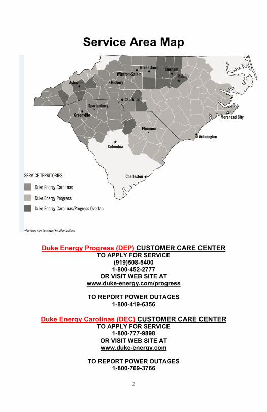
Service Area Map
Duke Energy Progress (DEP) CUSTOMER CARE CENTER TO APPLY FOR SERVICE
(919)508-5400 1-800-452-2777
OR VISIT WEB SITE AT www.duke-energy.com/progress
TO REPORT POWER OUTAGES
1-800-419-6356
Duke Energy Carolinas (DEC) CUSTOMER CARE CENTER TO APPLY FOR SERVICE
1-800-777-9898 OR VISIT WEB SITE AT www.duke-energy.com
TO REPORT POWER OUTAGES
1-800-769-3766

3
SECTION I
INTRODUCTION
The Company constantly strives to maintain a high standard of service to all Customers. This book has been prepared for use by Customers, architects, engineers, electrical contractors and local inspecting authorities so they may receive full benefit from Company’s service. The purpose of this book is to be of assistance when planning new electrical installations, revamping old ones or adding additional equipment. All users of “Requirements for Electric Service and Meter Installations” books are encouraged to submit proposals to aid in future revisions. Please submit proposals as follows:
1. Give section, paragraph and page number to which proposal pertains.
2. Submit proposal in writing. Include details, sketches, drawings and all pertinent supporting information.
3. Questions or comments can be sent to: [email protected] DEP Metering [email protected] DEC Metering
[email protected] Standards
Except for the installation and maintenance of its own property, the Company does not install or repair wiring on the Customer's premises and, therefore, is not responsible for the electricity beyond the P. O. D. and does not assume any responsibility for, or liability arising because of the condition of wires or apparatuses on the premises of any Customer beyond this point.

4
SECTION II
GENERAL INFORMATION
A. DEFINITIONS The following definitions shall apply for terms used in this book. ANSI – American National Standards Institute. Authority Having Jurisdiction – A person or agency authorized by a
governmental body to inspect and approve Customer electrical installations.
Available Fault Current – The maximum current that would flow due to a direct short from one conductor to ground or between conductors at the point of calculation. Cogeneration – See Interconnection. Company – Duke Energy
Contribution-in-Aid of Construction (CIAC) – The added cost paid by a Customer or developer to have the Company install service facilities costing more than that normally recovered through the monthly energy and Demand charges.
Customer – User of the Company's electric service or the user’s authorized representative (architect, engineer, licensed electrical contractors, etc.).
Demand – The average rate at which electric energy in kW, kVA or kVAR is consumed per time interval.
Demand Ampere – Average current flowing during the peak Demand interval.
Emergency and Standby Generators – Generators that normally operate only when the Company's electric service is unavailable and which are normally connected in such a way that no Interconnection can exist.
IEEE – Institute of Electrical and Electronic Engineers, Inc.
Instrument Transformer – Current Transformer (CT) or Voltage Transformer (VT) used to obtain current or voltage levels required for metering circuits.
5
Interconnection (Cogeneration and Small Power Producers) – An electric service where cogenerators and small power producers operate in parallel with the Company's electric system. Energy may flow in either direction through an Interconnection. Meter Enclosure – A device which houses a Meter Socket and line and load terminals. Meter Socket – A device which provides support and means of electrical connection to a watt-hour meter NRTL – Nationally Recognized Testing Laboratories such as UL, MET Labs, ETL, TUV, etc. National Electrical Code (N.E.C.) – A code sponsored by the National Fire Protection Association for the purpose of safeguarding persons and property from hazards arising from the use of electricity. National Electrical Safety Code (N.E.S.C.) – A code sponsored by the Institute of Electrical and Electronics Engineers, Inc. under the auspices of the American National Standards Institute for the purpose of the practical safeguarding of persons during the installation, operation or maintenance of electric supply and communication lines and associated equipment.
Point Of Delivery (P.O.D.) or Delivery Point– The point, as designated by the Company, where the Company's overhead Service Drop, underground Service Lateral, or transformer secondary bushings connect to the Customer's Service Entrance conductors. Power Leg (High-Leg) – The conductor in a three-phase, 4-wire delta secondary connection that has a higher voltage-to-ground potential than the other conductors. Premise – the street address (physical location) to which the Company provides electric service: a house, apartment, business, area light, or street light. Every electric service account is associated with a premise, although a premise may have more than one account associated with it. For example, if a Customer has a separately metered shop behind his house, the shop and house must be on separate accounts, but they are associated with the same premise.
Service – The supply of electricity from the Company to the Customer,
including the readiness and availability of electrical energy at the Point of Delivery at the standard available voltage and frequency whether or not utilized by the Customer.
Service Drop – The overhead service conductors between the Company's facilities (last service pole) and the Point of Delivery to the Customer's property.

6
Service Entrance – Normally, Customer-owned wire and/or enclosures,
connecting the Customer's service equipment to the Company's Service Drop, Service Lateral, transformer bushings or other source of supply.
Service Lateral – The underground service conductors between the Company's secondary conductors or transformers, including any risers at a pole or other structure and the Point of Delivery.
Solar Photovoltaic (PV) System – The total components and subsystems that, in combination convert solar energy into electric energy suitable for connection to a utilization load.
Tariffs – The applicable rates and electric service rules and regulations under
which all energy is delivered and all service is rendered by the Company.
Temporary Construction Service – Electrical service provided temporarily for the purposes of providing electricity to aid in the construction of a permanent facility.
Temporary Service – Service to non-permanent locations such as fairs,
displays, exhibits, and similar temporary purposes.

7
B. AVAILABILITY AND LOCATION OF SERVICE 1. Information concerning the availability of Service for a desired location
shall be provided by the Company. The Company, in all cases, shall designate the normal P.O.D. The Company shall make extensions to its existing facilities when required, and a Customer CIAC may be required. These extensions shall be to the point that allows the Company to provide Service in the most economical and practical means. Should additional facilities be requested by the Customer, additional fees shall be required to cover added cost.
2. To ensure that the Service connection shall be made promptly, and that
Company equipment has adequate capacity to provide satisfactory service to the Customer, cooperation between the Customer and the Company is necessary. The Customer shall submit appropriate load data to the Company. Contact your local Duke Energy engineer to determine the required load data and necessary forms. Before construction is started, the Customer shall request the Company to designate a normal P.O.D. The request for P.O.D. location is not an application for Service to the permanent building.
3. It is imperative that the Company and the Customer be in agreement with
the planned location of all Service-related equipment before construction is started. However, the Company shall have the final authority to determine the location. This equipment includes meters, risers, pedestals, pull boxes, CT/VT cabinets, transformers, etc. The selected Service equipment location must also meet the N.E.C. and all local ordinances, including any flood elevation requirements.

8
C. APPLICATION FOR SERVICE
Duke Energy Progress (DEP)
To obtain Service at the desired time, an application for Service shall be made by the Customer or owner during construction or as far in advance of the occupancy of the building as possible. Service contracts and/or deposits may be required prior to Service connection.
To apply for service:
By E-mail: [email protected] or use our Web site www.duke-energy.com/progress to:
• Apply for service
• Check your work request status: Builder/Customer number required
By Fax: Builder FAX Line 1-800-706-7488 24 hours a day – 7 days a week Company will fax a confirmation to you within 2 to 3 business days. Use the
Builder Request Form. By Phone: Builder Express Line 1-800-636-0581 7 A.M. – 6 P.M. Monday – Friday Company’s busiest days are Mondays and days after holidays. Have your builder/Customer number ready.
ESTABLISHING TEMPORARY CONSTRUCTION SERVICE 1. Builder arranges for electrician to set the temporary meter base. See
Figures 1A (DEP UG) and Figure 2 (OH).
2. Builder contacts the Company by Web site, fax, or phone with
builder/Customer number and specifies whether Service to be installed needs to be underground or overhead. A Company representative enters application for Service and holds for inspection and/or construction if needed. Representative issues premise number for use during all transactions at this location.
3. If it is necessary, the Company begins line construction process (requires
a minimum of 10 business days).
9
4. Builder arranges for inspection of temporary meter base by the Authority
Having Jurisdiction and supplies Inspector with premise number.
5. City/county performs inspection and notifies the Company of results prior
to meter being installed. (Process may vary from county to county.)
6. Company sets meter within one to four business days once inspection is
received and construction is complete, if needed.
ESTABLISHING PERMANENT SERVICE FOR A NEWLY CONSTRUCTED RESIDENCE
1. Builder completes final grade of property, clears right-of-way, and has
meter base set on house. If permanent Service is to be in owner’s name,
builder should give premise number to owner.
2. Builder contacts the Company by web site, fax, or phone to request
permanent Service, provides premise number and the following
information: length of underground service to be installed, if needed;
demographics of construction (heat type, square footage, etc); and
whether Temporary Service needs to be removed when permanent meter
is set. A Customer Care Specialist enters application for service and
holds for inspection and/or construction if needed. If it is necessary, the
Company begins line construction process .
3. Builder arranges for inspection of meter base and supplies Inspector with
premise number.
4. AHJ performs inspection and notifies the Company of results prior to
meter being installed. (Process may vary from county to county.)
5. Company sets meter on permanent meter base once inspection is
received and construction is complete, if needed. See Figures 4A, 4B, 5,
8, 9A, 9B, 10, and 11.
ESTABLISHING SERVICE FOR A NEW MANUFACTURED HOME
1. Upon final grade of property, homeowner confirms that meter base is set
and right of way is cleared. See Figures 4A, 4B, 9A, and 9B.

10
2. Homeowner contacts the Company by phone or fax to request permanent
Service and provides the following information: demographics of
construction (heat type, square footage, etc.).
3. A Customer Care Specialist enters application for service and holds for
inspection and/or construction if needed. Specialist issues premise
number for use during all transactions at this location. If line construction
is necessary, the Company begins line construction process.
4. Homeowner arranges for inspection of permanent electrical installation
and meter base and advises Authority Having Jurisdiction of premise
number.
5. Authority Having Jurisdiction performs inspection and notifies Company of
results prior to meter being installed. (Process may vary from county to
county.)
6. Company sets meter on permanent meter base once inspection is
received and construction is complete, if needed.
ESTABLISHING PERMANENT SERVICE FOR A NEWLY- CONSTRUCTED COMMERCIAL BUSINESS 1. Builder contacts the Company by web site, fax, or phone to request
permanent service. See Figures 20, 21, 28, 40, 47A, 47B, and 52. 2. The Company Representative provides the premise number. The
builder provides the following information: length of underground service to be installed, if needed; demographics of construction (heat type, square footage, etc.); and whether temporary service needs to be removed when permanent meter is set. Company Representative enters application for service and holds for inspection and/or construction if needed. If it is necessary, the Company begins line construction process
3. Builder completes final grade of property and clears right-of-way. If
permanent service is to be in owner’s name, builder should give premise number to owner.
4. Company Representative creates order and informs engineering of new
commercial job and creates new account number. 5. If the Customer requires Transformer-rated metering, the Company
Representative communicates meter information to meter technician

11
and creates a meter order. Otherwise, a self-contained meter is required. (See SECTION IV)
6. Company installs Transformer-rated metering equipment. 7. Builder arranges for inspection of their electrical service and supplies
inspector with premise number. 8. City/county performs inspection and notifies the Company of results
prior to meter being installed. (Process may vary from county to county.) 9. Company energizes new account once inspection is received,
construction is complete, installs a self-contained meter (if required), and completes connect set order.
D. APPLICATION FOR SERVICE Duke Energy Carolinas (DEC)
To obtain Service at the desired time, an application for Service shall be made by the Customer or owner during construction or as far in advance of the occupancy of the building as possible. Service contracts and/or deposits may be required prior to Service connection. Contact Company as early in the planning stage as possible. This allows adequate time to secure any rights of way, plan and build any lines needed, spot meter location and complete any other work required to install electric service. Applications are available for both temporary and permanent service online or by fax. To request an application call 800-454-3853 or visit duke-energy.com. TEMPORARY CONSTRUCTION SERVICE Prior to beginning construction, Customer will complete an application for electric service. This application for Temporary Construction Service alerts Company of the need for construction site power and also enables Company to set up the account using the appropriate rate. Standard for temporary services are found in Figure 1B (DEC UG) and Figure 2 (OH). NONSTANDARD TEMPORARY CONSTRUCTION SERVICE Charges will be applied to any nonstandard temporary construction service.

12
RESIDENTIAL SERVICE: PERMANENT OVERHEAD (Site-built, manufactured and modular homes service)
Service to a manufactured home generally follows the same guidelines as permanent residential service to a site- built house. Single-wide manufactured homes normally have the meter enclosure mounted on a service pole or structure. See Figures 4A, 4B, 5, 8, 9A, 9B, 10, and 11. Customer’s service pole should be placed so that Company primary, secondary and service conductors do not cross over the manufactured home. Note for single-family homes: The electric meter on a single-family residence should be located on the exterior of the structure on the side closest to Company’s equipment (pole, padmount transformer or service radial). Important note for manufactured homes: Since a manufactured home can be set up on site within 24 hours, Customer should notify Company as soon as a site is chosen. This will allow adequate time to coordinate a method of service including primary line work, if necessary, and enable Company to plan accordingly. RESIDENTIAL SERVICES: PERMANENT UNDERGROUND (Site-built, manufactured and modular homes)
After reviewing Customer application for service, Company may contact Customer to obtain additional information. Company will need to determine at this meeting whether Company’s conductors will lie under any concrete or structure (driveway, deck, patio, etc.). If so, arrangements will need to be made to avoid any future damage to Customer’s property should the cable require repair or replacement. Note: The electric meter on a single-family residence should be located on the side closest to Duke Energy’s equipment (pole, pad-mount transformer or service radial). A clear route between the power source and the meter enclosure must be maintained to avoid charges. If a driveway is to be placed in this route and needs to be installed before the underground service is installed, Customer will need to install a 3-inch Schedule 40 electrical gray conduit (with a pull string) with a minimum 30-inch cover from the top of the conduit, making sure both ends of the conduit are clearly marked above ground. METER BASE READY POLICY DEC’s standard practice is to install service cables to permanently installed approved meter bases to streamline installation and to avoid damage to service cables. A permanently installed meter base includes load wires,

13
ground rod and the grounding conductor. If there are situations that prevent Customer from doing this, Company may mutually establish a “guaranteed” meter base location. However, once the “guaranteed” meter base location is specified and the underground service is installed, Customer will be responsible for all costs associated with relocating Duke Energy facilities to a new meter base location. COMMERCIAL SERVICES
To obtain commercial service, Customer will call Duke Energy at 800-653-5307. A Company specialist will receive the necessary business and electrical load information from Customer. If electrical load information is unknown, Company can mail or fax an electrical load information form and Customer electrical contractor or other electrical consultant can determine electrical needs (load, conductor size, delivery voltage, etc.). Duke Energy will need time to secure any rights of way, plan and build any lines needed and complete other line work required to install the electrical service. Refer to Figure 15 for standard metered service voltages. COMMERCIAL SERVICES: PERMANENT OVERHEAD For commercial self-contained services, the following requirements must be met: (See SECTION IV, A, 4) Customer furnishes and installs: • Riser, weatherhead, ground rod and grounding conductor, and meter enclosure. • Refer to Customer-Purchased Equipment in Section IV(b). Refer to Figures 47A, 47B, and 47C for meter trough installations. The Duke Energy- approved meter enclosure is available from your local equipment supplier. • Final inspection before the meter is installed. • Attachment point – Should be located below the weatherhead except where it is impractical to do so because of clearance requirements. The height of the attachment point is dictated by the N.E.C. In those cases where it is impractical, the weatherhead must be within 24 inches of the point of attachment. See Figures 9A, 9B, 10,11, 12, and 13.

14
Company furnishes and installs: • Service cable • Connectors and connections Note: For commercial transformer-rated service, call 800-653-5307. COMMERCIAL SERVICE: PERMANENT UNDERGROUND Customer will need to identify all existing and proposed underground facilities so to prevent damage during installation of underground electrical facilities. For commercial self-contained service, the following requirements must be met: (See chart in SECTION IV, A) Customer furnishes and installs: • Service pole, if required • Ground rod and ground wire • Meter enclosure – Position the meter enclosure so the meter is a minimum of 3 feet or a maximum of 6 feet from final grade. Refer to Figures 4A and 4B. Meter trough installation requirements are contained on Figures 47A, 47B, and 47C.The Duke Energy-approved meter enclosure is available from your local equipment supplier. A 200-amp meter enclosure minimum is required. • Final inspection before the meter is installed Duke Energy furnishes and installs: • Conduit into meter enclosure • Underground service conductor from an overhead energy source to the Customer’s meter box Note: For commercial transformer-rated service, call 800-653-5307. (See Figure 43A.)

15
E. TYPE OF SERVICE 1. IT IS ESSENTIAL THAT THE CUSTOMER CONTACT THE
CUSTOMER CONTACT CENTER REGARDING TYPE OF SERVICE THAT CAN BE FURNISHED AT A PARTICULAR LOCATION BEFORE PROCEEDING WITH PURCHASE OF EQUIPMENT OR INSTALLATION OF WIRING.
2. Service is provided with alternating current at a normal frequency of sixty
(60) hertz (cycles per second).
3. The voltage and/or number of phases which shall be supplied shall depend on the type, size and location of the load, and existing Company facilities. Single-phase Service or three-phase Service shall be provided according to the following:
(a) Residential Customers and commercial Customers located in
predominantly residential areas shall normally be provided with only 120/240 volt, 3-wire, single-phase Service. Three-phase Service to such Customers may be supplied if loads warrant such Service and the required Company facilities are readily accessible. The Customer may be charged a CIAC.
(b) In multi-occupancy buildings or complexes served by 208Y/120 volt
three-phase facilities, normal Service to individual occupancies shall be 120/208 volt 3-wire single-phase (a five-terminal meter enclosure is required).
(c) Commercial Customers located in commercial/industrial areas shall
be provided three-phase Service if it is currently available at the location and if loads warrant such Service. If three-phase service is requested and the above conditions are not satisfied, the Customer may be charged a CIAC.
4. The manner in which single-phase load is connected by the Customer is
critical with three-phase service. On 208Y/120 volt or 480Y/277 volt "wye" three-phase Services, all single-phase loads should split evenly among the three phases. On 240/120 volt "delta" three-phase 4-wire services, all single-phase 120 volt loads shall be connected only to the 120 volt-to-ground legs. NO SINGLE-PHASE LOAD SHALL BE CONNECTED PHASE TO GROUND TO THE HIGH LEG. Connections made otherwise may result in damage to the Customer's equipment.
5. See Figure 15 for standard metered services voltages.

16
F. INSPECTION
1. The Customer’s electric service installation including wiring and equipment shall be installed in accordance with the adopted edition of the N.E.C. and local ordinances.
2. All service installations shall be inspected and approved by the AHJ as
required by law. The Company cannot connect any temporary or permanent electric service and set a meter until the Company has been notified by the AHJ that the proper inspections have been completed and approved. To avoid delay in getting service, please apply to Duke Energy for permanent service before the final inspection has been completed.
3. The Company shall make an inspection of the service installation to
verify compliance with requirements of this book. If the service installation does not meet these requirements, the Company will refuse to connect the service. A reasonable effort will be made to notify the Customer of any changes required.
4. The Company may refuse to connect service to any new or altered
installation which the Company or the AHJ considers unsafe. The Company may also disconnect service at any location that is unsafe or shows evidence of tampering or current diversion.
5. Temporary emergency restoration of service to an existing Customer
service installation shall be made in accordance with the Company’s rules and regulations and the AHJ.
G. ALTERATIONS AND ADDITIONS
For changes in permanent overhead or underground service If the Customer’s electrical service needs changing, additional load is
being added, or electrical facilities need relocating, the Customer will
need to update their service application information by contacting the
Company as early in the planning process as possible. This allows the
Company time to secure any additional rights of way, modify or build any
needed lines and complete any other work required to meet the new
electrical needs.

17
Requirements 1. Service connections, Company-owned meters or metering equipment, by law, shall not be removed or relocated except by employees or duly authorized representatives of the Company.
2. Connection to the Customer’s premises is made with facilities designed to properly supply adequate electric service using information provided on the application for service. Therefore no additions of major load or alterations of the Customer’s installation should be made without first notifying the Company. Failure to provide such notification may affect the quality and reliability of the Customer’s service and also that of other Customers supplied from the same facilities. Also, failure to provide adequate notice to the Company could subject the Customer to charges for any loss of or damage to the Company’s facilities.
3. An application for changes in the service provided by the Company shall be made by the Customer in the same manner as application for new service.
4. When the Customer requests a change in the existing service characteristics, the requirements outlined in Figure 15 shall apply.
5. When alterations require the relocation of any service equipment, the Customer shall make appropriate advance arrangements with the Company. When the Customer’s part of the alterations have been satisfactorily completed and the necessary inspection approvals have been obtained, the Company shall make the connections to provide service. The Customer may incur a CIAC charge.
H. RIGHTS AND RESPONSIBILITIES
1. The Company shall have the right of ingress to and egress from the Customer’s premises for any and all purposes associated with the delivery of service including installing, removing, testing or replacing equipment and for reading meters.
2. All reasonable care shall be exercised by the Customer to prevent loss or damage to all property of the Company installed on the Customer’s premises used in supplying service.
3. The Customer shall furnish the Company a satisfactory and lawful right
of way over the premises for the Company’s lines and apparatus necessary or incidental to the furnishing of service.
4. The Customer shall be held responsible for breaking the seals,
tampering or interfering with the Company’s meter(s) or other equipment

18
installed on the Customer’s premises. No one except authorized employees/agents of the Company shall be allowed to make any repairs or adjustments to any meter or other piece of equipment belonging to the Company.
I. ELECTRICAL CONTRACTOR SEALING POLICY
A licensed electrical Contractor must notify the Company the day before breaking and removing the meter seal to perform work, and must notify the Company immediately following any work so that Company can re-inspect the facilities and place a Company seal.
J. REFUSAL OR DISCONTINUANCE OF SERVICE BY THE
COMPANY
The Company may refuse or discontinue Service for certain reasons. Several of these reasons are listed below. 1. Non-payment of bills for electric service. 2. Refusal or failure to make a deposit when requested. 3. Failure to rectify a deficiency or defect in the Customer's wiring or
other facilities after receiving notice from the Company that such condition exists.
4. Unauthorized use of electric energy. 5. Operation of equipment which causes voltage flicker or objectionable
Service characteristics to other Customers. 6. Neglect or refusal to provide safe and reasonable access to the
Company. 7. Tampering with meters or other facilities furnished and owned by the
Company. 8. A hazardous condition is found by the Company.
19
K. Use of Company Rights-of-Way
Distribution Line Rights-of-Way (less than 44KV) The Company’s distribution easements cover overhead and underground facilities. The overhead facilities have a minimum width requirement of thirty (30) feet wide, extending fifteen (15) feet on each side of the center line of the electric facilities. The underground facilities have a minimum width requirement of ten (10) feet wide, extending five (5) feet on each side of the center line and ten (10) feet on each side of an electrical enclosure. Greater right-of-way widths may be required by Company engineering personnel under certain circumstances and will be stated on the easement form.
The property owner may use the right-of-way for other purposes, not in conflict with the easement rights granted or in violation of applicable safety codes. The Company’s easement grants the Company the right to construct/install, operate, maintain, upgrade, clear, and access its facilities at all times. Before constructing or placing structures near Company lines, the Customer must call the Customer Call Center to discuss the proposed plans with a Company representative to ensure that the Customer is not encroaching upon Company easement rights. Some encroachments may be allowed within the rights-of-way but must have proper Company approval prior to construction. Call 811 or NC One Call 800-632-4949 or SC PUPS 888-721-7877 to ensure any electric line is located prior to digging or excavating.
Transmission Line Rights-of-Way (Voltages 44KV & higher) The Company’s transmission lines have varying rights-of-way widths ranging from approximately 70 feet to over 300 feet in width and easement rights that cannot be encroached upon by others. Before any use of the transmission rights-of-way can be approved, the Customer must contact an Asset Protection Specialist through the Customer Service Center. Proposed plans must be reviewed, approved and meet all applicable Transmission Guidelines and Restrictions. This document can be accessed via the Duke Energy website at: http://www.duke-energy.com/safety/right-of-way-management.asp

20
The Guidelines and Restrictions have been developed to answer the most frequently asked questions about property owner use of Duke Energy’s electric transmission rights-of-way. Construction trailers, meter bases, pad mount transformers, temporary services, telephone and cable pedestals are a few examples that are not permitted within the transmission rights-of-ways. This list does not cover all restrictions or all possible situations. These restrictions are subject to change at any time and without notice. Duke Energy reserves all rights conveyed to it by the right-of-way agreement applicable to the subject property. Engineering plans may be required. The Company’s easement grants the Company the right to construct/install, operate, maintain, upgrade, clear, and access its facilities at all times. If the Company approves any use of the rights-of-way, it will be done in the form of a written agreement or a letter of “No Objection” via the local Transmission Asset Protection Specialist. If you have any additional questions or plan any activity within the transmission rights-of-way, call the Duke Energy Customer Care Center at 800-777-9898.

21
SECTION III
SERVICES A. GENERAL INFORMATION
1. Normally, there shall only be one Service voltage available at a location
and only one P.O.D. for each building. Exceptions may be allowed as noted in N.E.C. 230.2 and if agreed upon by the Company.
2. P.O.D.: For Service to each Customer, there is a definite P.O.D. at
which the responsibility of Company ends and the responsibility of the Customer begins. Company will install, own, operate, and maintain all facilities on its side of the point of delivery and will have exclusive control of all electricity before it passes such P.O.D. The Customer will normally install, own, operate, and maintain all facilities (exclusive of metering equipment) on the Customer’s side of the P.O.D. and will have exclusive responsibility for all electricity after it passes the P.O.D. The Customer will not own, install, operate or maintain any facilities on the Company’s side of the P.O.D. The P.O.D. will be designated by the Company.
3. All Service Entrance facilities, including meter enclosures, shall be located
in an exposed or readily accessible area. 4. Customer load wires shall never be installed in raceways that contain
non-metered wires. 5. Grounds shall be established as required by the N.E.C., AHJ,and the
Company. 6. CONDUCTOR MARKING
a. The "208 volt phase-to-ground" (high leg - right hand side, c position
in the meter base) of each 240/120 volt 4-wire three-phase Service shall be clearly marked with an orange marking at the Point of Delivery and at the meter location or CT cabinet.
b. Phase conductors other than the "high leg" phase shall be clearly
marked with color markers at the P.O.D. and at the meter location if more than one conductor per phase is used. Colors used for this purpose shall be the option of the electrician but shall be the same color for each conductor of the same phase. Phases to be marked A, B, C on CT installations.

22
Note: The Company uses the following color notation for A, B, and C phase marking.
DEC / DEP
208Y/120v Three phase Red-Yellow-Blue
240/120v Three phase Red-Yellow-Orange
480Y/277v Three phase Red-Yellow-Blue
7. Customer conductor labeling for Multi-tenant metering:
Where one service is C.T. metered on the pad-mounted transformer AND other Customer-owned Services are run to the same transformer, BUT are metered elsewhere (i.e., on building wall or in meter room): both ends of ALL Customer cables must be clearly and specifically marked for phase AND labeled with a tag to identify the location of the source and load ends of the cable. The load end of each cable shall be labeled to identify the source. Each source end shall be labeled to identify the location of the load end of the cable (trough number, switch panel number, etc.). Refer to Figure 3.
8. Where three-phase Service is provided, the Company will provide
phasing as follows: Random (either ABC positive sequence, Clockwise, OR CBA negative sequence, Counterclockwise) Customer must confirm and make any necessary adjustments once service is connected.
B. TEMPORARY SERVICE\TEMPORARY CONSTRUCTION
SERVICE
1. Temporary Service is used when a Customer requests a Service that is
not used for construction of a permanent structure that will receive permanent Service after construction is complete. An example would be a temporary sales lot used as a Christmas tree sales lot. Contact the local Company representative for details and charges.
2. Temporary Construction Service is used to provide power to a permanent structure under construction with the understanding that upon completion of that structure, permanent Service will be provided. For electric service of 120/240 volts, single phase, 200amps or less, there are no charges to the Customer if the overhead construction Service Drop is 100 feet or less, or no more than 2 feet of underground service lateral. Temporary Service for construction purposes (Temporary Construction Service) may be either overhead or underground depending upon

23
availability. Arrangements for providing temporary service/temporary construction service are shown in Figure 1 and Figure 2.
C. OVERHEAD (OH) SERVICES 1. It is the Customer's responsibility to provide a suitable support for
attachment of the Service Drop conductors. See Figures 8, 9A and 9B 10, 11, 12, and 13. Customer is responsible for providing and installing an attachment point for the Service Drop conductors.
2. A minimum of two (2) feet of Service Entrance wire shall be left projecting
from the weatherhead for connection to the Service Drop. The conductors shall be marked for phase identification at a point one (1) foot outside of the weatherhead.
3. For Service to mobile homes and other installations requiring overhead
service equipment poles, refer to Figures 9A and 9B. 4. Thru-the-roof risers must be accessible to a Company bucket truck or
Company extension ladder. Risers in excess of 72" above rooflines shall be accessible to Company bucket trucks.
5. The Customer may be charged a C.I.A.C. for any cost incurred by the
Company as a result of relocation or repair of Company facilities necessitated by grade changes, additions, swimming pools, etc.
D. UNDERGROUND (UG) SERVICES 1. In certain areas where the Company has UG distribution, UG service shall
be used, and OH Service shall not be available to the Customer. 2. For Service to mobile homes and other installations requiring
underground service equipment poles, refer to Figures 4A and 4B.
3. The Customer may be charged a “Contribution-in-Aid of Construction” for any cost incurred by the Company as a result of relocation or repair of Company facilities necessitated by grade changes, additions, swimming pools, etc.
4. The Customer is responsible for all necessary grass reseeding or
application of sod or straw necessitated by the Company’s initial installation of facilities.
5. The Customer is responsible for any abnormal construction costs such
as, but not limited to, mechanical tamping, excessive hand digging, rock
24
removal, sidewalk boring, driveway and street boring, etc. Also, Customer is responsible for providing protection barriers for padmounted transformers whenever they are subject to vehicular traffic. (Figure 61)
6. Customer service conductors run to Company-owned padmounted
transformers must be stubbed out within the allotted space. Refer to Appendix C (for DEP) or Appendix D (for DEC) for stub-out details. Refer to Figure 58 for the maximum number and size of Customer conductors allowed in padmounted transformers. A secondary buss enclosure as defined by Company representative will be required if the Customer conductor count exceeds the maximum.
7. Customer service conductors run to Company-owned padmounted
transformer terminals will be terminated by Company personnel. Each phase of parallel conductors will be cut the same length per N.E.C. Article 310.10 (H)(2). Marking of conductors should be placed on each conductor one foot above the conduit exist to ensure the marking is not cut off.
8. Any obstruction (on the wall, footer, etc.) which prevents installation of the
Company's conduit shall be removed by the Customer.
9. Company’s line extensions, including Services, shall be installed under the terms of the Company's filed rates and Tariffs.
10. The Customer shall request the Company to designate the P.O.D. for
each service location before construction is started. 11. Special routing may incur additional cost to the Customer.
12. It is important that the Customer contact the Company to determine the
voltage that is available at a desired service location before construction is started.
13. When converting residential overhead Service Drop to underground,
provisions of the Company’s filed rates and tariffs will apply. Additional costs may be required for boring sidewalks, driveways, roads/streets and other adverse conditions.
E. LIGHTING SERVICES A variety of lighting options, including standard, decorative, and flood, are offered by the Company for both residential and commercial/industrial applications. Contact the Customer Care Center at 866-769-6417 for further information and to talk to a Company representative.

25
SECTION IV METERING INSTALLATIONS A. GENERAL REQUIREMENTS 1. Jurisdictional Differences
DEC The Company shall furnish, own, and maintain all meters and transformer rated meter sockets. The Customer shall furnish, install, own and maintain all self-contained meter sockets, current transformer cabinets, transockets, and metering troughs.
DEP The Company shall furnish, own, and maintain all meters, transformer rated meter sockets, and some current transformer cabinets (See Figure 43B for details). The Customer shall furnish, install, own and maintain all self-contained meter sockets and metering troughs.
2. It is the Customer’s responsibility to furnish to the Company specific information on the type of service required such as overhead or underground, service voltage(s), main line switch amps, maximum demand amps and the number and size of the Customer’s service entrance conductors.
DEC – Contact the local Duke Energy representative. For non-residential service the Customer must provide this information on a Load Sheet Form. A copy of the Load Sheet is shown in Appendix A.
DEP - Contact the local Company representative.
3. A transformer-rated service from a three-phase padmount transformer
serving a single Customer will be metered at the padmount transformer.
The Customer will pull service conductors to the transformer (See
Figure 28).
4. A transformer-rated service from a single-phase padmount transformer serving a single Customer will be metered on the building wall (See Figure 21) or on an approved meter structure. Service conductors will be installed by the Company, or by the Customer, depending on the established P. O. D. as specified by Company Representative.
5. For non-residential self-contained metered services or services to
trough installations, the Company provides the underground service
conductors from the padmount transformer to the P. O. D. (See Figures
28, 47A, 47B, and 47C).

26
6. The information below and in the chart on Page 27 indicates the type of metering required for different service configurations. Company Representative will answer any questions about the type of service required for the installation.
(a) On installations where the nominal voltage does not exceed 240 volts and the anticipated demand current does not exceed 200 amperes, an approved 200 ampere self-contained meter enclosure shall be used. See chart on Page 27.
(b) On installations where the nominal voltage does not exceed 240 volts and the anticipated demand current is greater than 200 amperes but does not exceed 320 amperes continuous or 400 amperes maximum, an approved 400 ampere self-contained meter enclosure shall be used. A Class 320 meter shall be installed by the Company. See chart on Page 27.
(c) On installations where the service voltage exceeds 240 volts or the Company determines the demand will exceed 320 amperes continuous or 400 amperes maximum for single phase or three phase services, instrument transformer metering shall be required. See chart on Page 27. No new 600 amp K-base installations will be connected.
(d) See SECTION IV, D for more information on instrument transformer rated service installations
(e) Refer to Figure 21 for typical field applications of transformer-rated metering versus self-contained metering, single and three phase.

27
Duke Energy Standard Metering Requirements for Various Service Voltages
NOTES:
1. Meters and sockets rated for 400 amps maximum, 320 amps continuous.
Meter Service Type Service Configuration
0 – 200 Amps 201-400 Amps > 400 Amps
Three-wire, 120/240V Single Phase
Self-contained, 200 amp Four terminal Form 2S
Self-contained, 320 amp Four terminal Form 2S. (see note 1)
Transformer rated Five terminal Form 3S
Three-wire, 120/208V Network
Self-contained, 200 amp Five terminal Form 12S
Self-contained, 320 amp five terminal Form 12S. (see note 1)
Transformer rated Eight terminal Form 5S (45S)
DEC - Self-contained, Form 12S five terminal 200 Amp.
DEC – Self-contained, 320 amp five terminal Form 12S (see note 1)
Three-wire, 240V Delta Three Phase
DEP – Self-contained, Form 16S seven terminal 200 Amp.
DEP – Self-contained, Form 16S seven terminal 320 Amp (see note 1)
Transformer rated Eight terminal Form 5S (45S)
Three-wire, 480V Delta Three Phase
Transformer rated Eight terminal Form 5S (45S)
Transformer rated Eight terminal Form 5S (45S)
Transformer rated Eight terminal Form 5S (45S)
Four-wire, 240V High-leg Delta Three Phase
Self-contained, 200 amp Seven terminal Form 16S
Self-contained, 320 amp Seven terminal Form 16S (see note 1)
Transformer rated Thirteen terminal Form 9S
Four-wire, 120/208V Wye Three Phase
Self-contained, 200 amp Seven terminal Form 16S
Self-contained, 320 amp Seven terminal Form 16S (see note 1)
Transformer rated thirteen terminal Form 9S DEC - see note 2
Four-wire, 277/480V Wye Three Phase
Transformer rated thirteen terminal Form 9S DEC - see note 2 DEP - see note 3
Transformer rated thirteen terminal Form 9S DEC - see note 2
Transformer rated thirteen terminal Form 9S DEC - see note 2

28
2. For DEC services up to 600 amps where limited space
prevents the installation of a CT cabinet and meter socket, a
DEC-approved transocket may be used. See DEC
transocket specifications on Page 30.
3. For DEP services, VT Pack metering shall be permitted under the conditions stated on Figures 40 and 41.
4. All meter jaws must be factory installed.
5. On installations, repairs, replacement or upgrade of enclosures involving more than one meter on a single premise, the following guidelines apply:
a) The Customer shall purchase and use either individual meter sockets (single or three phase) for trough installations as shown in Figures 47A and 47B or ganged meter sockets as described in Section IV-B and shown in Figures 25, 26, and 27.
b) Each meter socket will be labeled on the outside front and on the inside as shown in Figure 3 correctly identifying the Customer served. Verification of correct labeling is the responsibility of the Customer.
c) On installations where the service voltage exceeds 240
volts or the Company determines the demand will exceed 320 amperes continuous or 400 amperes maximum for single phase or three phase services, instrument transformer metering shall be required. See chart of Page 27. No new 600amp K-base installations will be connected.
d) See SECTION IV, D for more information on instrument
transformer rated service installations.
e) Refer to Figure 21 for typical field applications of transformer metering versus self-contained metering, single and three phase.
B. CUSTOMER-PURCHASED EQUIPMENT
1. Effective July 1, 2016, only self-contained meter sockets including
individual meter sockets, ganged meter sockets, or multi-position meter centers that are on the Meter Equipment Group approved list may be used. In addition, all sockets and meter centers must comply with the mounting heights specified in this manual. The current list of MEG approved sockets is located on the Company website at the following locations:
29
http://www.duke-energy.com/pdfs/MEG-Approved-Sockets.pdf
2. The Customer shall be responsible for all maintenance of self-contained
meter sockets
3. DEC - Duke Energy Carolinas Customer-owned CT cabinet and transocket guidelines and general specifications: Guidelines: a. Customer furnishes and installs the CT cabinet. See Figure 43A for
CT cabinet size and mounting guidelines. See following section below for construction requirements.
b. CT cabinets must be installed in the correct orientation for which they
are designed. Cabinets mounted incorrectly can allow water to enter.
c. Additional space must be planned for the installation of the meter socket. Center of meter must be between 3 feet and 6 feet above final grade. Duke Energy technician will install the meter socket.
d. See Figure 14B for grounding requirements.
e. Customer will cut hole in the CT cabinet for Duke Energy’s riser for
underground service. Hole must be positioned at opposite end
of cabinet from Customer conductors and be sized per the chart
in Figure 43A.
f. Customer load side conductors should enter the cabinet from one side only.
g. Please consult Duke Energy Field Metering prior to construction for any questions or unusual circumstances.
General CT Cabinet Construction Specifications:
1. All CT cabinets:
(a) All CT cabinets shall be designed, manufactured and tested in
accordance with the specifications given in the latest revision of
the National Electrical Code and Underwriters Laboratories Inc.
Standard for Safety UL-50.
(b) All CT cabinets shall have a backboard made of ¾-inch-thick plywood affixed to the inside of the back CT cabinet wall with stainless steel screws or bolts. The backboard is for mounting instrument transformers. Other means can be provided for mounting CTs if determined by Duke Energy to be safe and offering sufficient mounting options.
(c) There shall be a grounding/bonding lug on the inside of the CT cabinet. See Figure 14B for grounding requirements.

30
(d) All CT cabinets shall have a latch assembly to accept a padlock- type seal and can be accommodated according to ANSI C-12.7.
2. CT cabinet 1:
(a) Rectangular CT cabinet 32 inches wide by 24 inches high by 12
inches deep minimum dimensions with lift-off cover and
mounting provisions for instrument transformers as specified
above.
(b) The enclosure shall be constructed using a minimum of .056-
inch galvanized sheet steel bonderized with a zinc coating or
.080-inch sheet aluminum.
(c) The front cover shall be lift-off type. The interior shall have door stops to prevent inward deflection of the front cover.
(d) The enclosure shall have two sealing facilities at the bottom of the cover.
3. CT cabinet 2:
a. Square CT cabinet 40 inches wide by 40 inches high by 14
inches deep minimum dimensions with double-hinged doors and
mounting provisions for instrument transformers as specified
above in Item 1.
(b) The enclosures shall be constructed using a minimum of
.063-inch galvanized sheet steel bonderized with a zinc
coating or .090-inch sheet aluminum.
(c) The enclosure shall have double doors with a minimum of two
hinges per door. The double doors shall have a three-point latch
operated by a single handle that can be secured by a padlock.
(d) There shall be a mechanism provided for holding the doors open greater than 90 degrees from the closed position.
4. CT cabinet 3:
(a) Square CT cabinet 60 inches wide by 60 inches high by 18
inches deep minimum dimensions with double-hinged doors and

31
mounting provisions for instrument transformers as specified
above in Item 1.
(b) The enclosures shall be constructed using a minimum of
.063-inch galvanized sheet steel bonderized with a zinc
coating or .090-inch sheet aluminum.
(c) The enclosure shall have double doors with a minimum of two
hinges per door. The double doors shall have a three-point latch
operated by a single handle that can be secured by a padlock.
(d) There shall be a mechanism provided for holding the doors open greater than 90 degrees from the closed position.
5. Transocket specification: (a) All transockets must be 13 terminal sockets for four-wire wye
services, 120/208 V or 277/480 V, 600 amp maximum.
Transockets must be pre-approved for use on the DEC system.
Transockets approved for use are Meter Devices Model:
683U3690-T092.
(b) A ll transockets shall meet the requirements for Underwriters
Laboratories Inc. Standard for Safety UL-50.
(c) All transockets shall have a backboard made of ¾-inch-thick
plywood affixed to the inside of the back wall with stainless steel
screws or bolts. The backboard is for mounting instrument
transformers. Other means can be provided for mounting CTs
if determined by Duke Energy to be safe and offering sufficient
mounting options.
(d) There shall be a grounding lug attached to the inside of the transocket capable of accepting #14 to #2 copper or aluminum conductors.
(e) All transockets shall have a latch assembly to accept a padlock-type seal and can be accommodated according to ANSI C-12.7.
(f) All transocket dimensions must be a minimum of 25 inches wide by 33 inches high by 12 inches deep.
C. METER LOCATION
1. The location of meters is an important consideration to both the Company
32
and the Customer. The Company shall always be consulted and shall endeavor to select a location that shall be the most suitable to both parties.
2. Meters shall be located in a place where they shall be protected from
mechanical damage. The Customer shall be responsible for providing this protection.
3. Meter sockets and enclosures shall be securely mounted in a plumb and level
position on a solid wall or structure. The Customer shall be responsible for
securely fastening the meter enclosure in order to withstand the normal forces
required to routinely remove and install the meter.
4. Meter enclosures shall not be recessed or framed in any way that
blocks access, knockouts or drainage.
5. The centerline of the meter shall not be more than 6 feet or less
than 3 feet from the ground (final grade) or floor. For meter centers, the
height of the bottom meter socket shall not be less than 30 inches. (See
Figure 27)
Exception: In flood zones where the requirements mandate that the
meter be located above 6 feet from grade, ready and permanent
accessibility to the meter (including the working space described in item
No. 6 in this section) shall be provided for reading and testing. See
Figure 5.
6. A clear space at least 30 inches wide (or equipment width whichever
is greater) by 42 inches deep by 78 inches high from final grade must
be provided and always be available around every meter for reading,
inspecting, testing and maintenance operations. Clear space for safe access
to and egress from the working space must be maintained.
7. Meters shall be installed outdoors or in a meter room as described in
No. 10 within this section. In developed downtown urban areas,
meters may be located indoors with the approval of Company
representative prior to installation.
8. Meters for single-family residences shall always be located outdoors.
Meters shall not be located in areas such as carports, open porches,
swimming pools, etc., which are susceptible to subsequent enclosures by
walls or screens. Any deviation shall be approved in writing by an authorized
Company representative.
33
9. In the event a meter is later enclosed or otherwise made inaccessible
or unsafe, the Customer shall, at the Customer’s expense, have the
meter facilities moved to a readily accessible outside location.
10. Meters may be grouped together in a meter room furnished by the
Customer provided the following requirements are met:
(a) A single meter room should normally be located on the first floor. For
buildings above three floors, a single meter room may be located on
various floors at mutually agreeable locations. Any exceptions to
this due to unusual distances, etc., must be approved by your
Duke Energy project engineer.
(b) The Company shall have access to the meter rooms for reading, testing
and servicing the equipment. When meters are located in areas that
can be locked, the Customer shall make arrangements to provide the
Company access to the meters. The Customer shall provide a lock
box to accommodate a standard key or a magnetic access card.
The lock box will be installed by the Customer.
(c) Meters installed inside shall be in a clean, dry, lighted, safe place and
be easily accessible at all times. They shall not be located in
restrooms, dressing rooms, bedrooms, kitchens, ventilating or elevator
shafts, boiler rooms, laundry rooms, hallways, etc. They shall not be
installed near belts or other moving machinery, endangering the safety
of those doing work near the meter.
(d) Adequate space, lighting and access shall be provided as
defined in consultation with the Company as the facilities are
planned. Using meter rooms for storage or other purposes that prohibit
safe access or adequacy of workspace shall not be allowed.
(e) Failure to maintain a safe, accessible location for meters shall require that they be relocated to an appropriate location at the Customer’s expense.
D. INSTRUMENT TRANSFORMER INSTALLATIONS
1. The use of instrument transformers shall be determined by the Company as
described in SECTION IV A(5).
2. It is very important to both the Company and the Customer that the

34
instructions and construction details shown in Figures 14B, 21, 43A,
and 43B are followed closely on all instrument transformer installations.
3. The facilities necessary for instrument transformer installations shall be
provided and installed as described below:
(a) The Company shall provide the instrument transformers, instrument
transformer secondary wiring, meter enclosure and meter.
(b) DEC - The Customer shall provide and install the current transformer
cabinets.
DEP-The Customer shall install the current transformer cabinets
provided.
4. Instrument transformer installations are usually made by one of the
means listed below, each of which requires coordination between the
Customer and the Company.
a) Indoor/outdoor current transformer enclosures are normally used when
the Customer receives either overhead or underground service.
(b) Instrument transformer installations in transformer vaults and
padmounted transformers are applicable only where the vault or
transformer provides service for a single Customer at a single rate. In these
cases, the following requirements apply:
(1) Meters shall not be located inside the transformer vault.
(2) Necessary meter wiring shall be installed and connected by the
Company’s meter technician.
(c) Services may have wall mounted or riser mounted overhead current
transformers.
(d) DEP - On 480Y/277V three phase installations where the
anticipated demand current does not exceed 200 amperes, VT pack
metering shall be permitted under the conditions stated on Figures 40
and 41. This service is mainly for mall applications where space is at a
premium.
5. A clear space at least 30 inches wide (or equipment width whichever
is greater) by 42 inches deep by 78 inches high from final grade must
35
be provided and always be available around every meter for reading,
inspecting, testing and maintenance operations. Clear space for safe access
to and egress from the working space must be maintained.
E. DEP ONLY - SURGE ARRESTERS
1. Surge arresters (whether Company-owned or Customer-owned) may be installed as depicted on Figure 46 provided the installation meets the safety standards set forth below and do not interfere with the voltage delivered or the proper registration of the meter. The standards set forth below are for safety-related reasons only and do not address the ability of the arrester to dampen or reduce surge events. Arresters installed shall bear the appropriate label or markings indicating that they have been manufactured to meet the required safety standards.
2. Surge arresters must comply with applicable ANSI/IEEE, UL or other nationally recognized testing laboratory (NRTL) safety standards.
3. See Figure 45 For additional conditions associated with devices installed between the meter and meter socket.
SECTION V
EQUIPMENT VAULTS A. GENERAL REQUIREMENTS
1. In a few situations, it may be necessary or convenient to install Company-
owned transformers and/or related equipment in a vault inside a Customer's building. In such cases, the Customer shall consult with the Company before plans are made concerning the vault.
2. The vault shall be constructed in compliance with Company requirements;
the N.E.C. and such local requirements as may be in force. 3. The vault shall not contain any Customer-owned equipment for building
service facilities such as: secondary fuses, switches, meters, load control equipment, gas, oil, steam or water pipes, or ventilation ducts other than those required by the Company.
4. The Company’s revenue meter location shall be within 25’ of the
instrument transformers on the same floor level.

36
5. Fire suppression systems should not be installed in Company equipment vaults unless specifically required by local authorities and then must be approved by the Company. Liquid sprinkler systems of any kind are not allowed.
6. The vault and its contents shall be under the supervision of the Company, and shall have provisions for locking and security sealing by the Company. Unauthorized persons shall not be permitted to enter vaults.
B. CUSTOMER RESPONSIBILITIES 1. The Customer shall provide and own the following facilities for use by the
Company:
a. Equipment vault sized and built in accordance with Company requirements.
b. All facilities required to provide natural or forced ventilation determined necessary by the Company.
c. All conduits within the building for Company's facilities, including primary and/or secondary conductors. Such conduits shall extend beyond the outside building wall to a point designated by the Company.
d. Access means including elevators and/or hoists where necessary, such that transformers and equipment can be moved from the street or sidewalk directly to and from the vault.
2. The Customer shall also provide properly executed easements on the Company's forms for all facilities installed on the Customer's property.
C. COMPANY RESPONSIBILITIES 1. The Company shall determine the physical requirements for each vault,
including minimum size, ventilation, lighting and conduits. The Company shall endeavor to work closely with the Customer so that the needs of the Company and the desires of the Customer are considered in the design and construction of the vault(s).
2. The Company shall provide and own the following:
a. Transformer(s) and/or additional necessary equipment b. Primary cable(s) and related connections c. Connections to Customer-owned service cable or bus

37
SECTION VI
CUSTOMER UTILIZATION EQUIPMENT
A. GENERAL 1. The Company builds and maintains adequate lines to supply proper
service to all Customers using normal equipment. However, since equipment installed by one Customer may materially affect the adequacy and continuity of service to other Customers, and because the misuse of some equipment might constitute a fire hazard or endanger life, the Company has established regulations covering the more common installations of utilization equipment.
2. The Company specifies only such requirements as are necessary to
safeguard both the Customer and the Company so that service may be rendered with a maximum of safety and with a minimum of interruption or disturbance. The Customer should consult the Company for additional details on special equipment which may not be covered in this book.
3. Available fault current shall be taken into consideration when specifying
Service Entrance equipment (See SECTION VII). 4. Protection of equipment against loss of voltage, under-voltage,
transient or sustained over-voltage, voltage unbalance, overcurrent, phase failure, phase reversal, loss of synchronism, harmonics and short circuit is the responsibility of the Customer.
B. MOTORS
When a Customer's motor starting causes objectionable flicker to other Customers, the Company shall require installation of devices such as reduced voltage or part winding starters to limit starting inrush currents to values that shall reduce flicker to acceptable levels. Where large motors using a converter-inverter are installed on single- phase distribution systems to provide three-phase power for the motor, harmonic filters will need to be installed. These large single- phase non-linear loads will cause excessive 3
rd harmonic current flows on the utility system without such
filters. Note that Item C 2. in the following section also applies to large motor loads.

38
C. SPECIAL EQUIPMENT
1. Due to the very severe operating characteristics of such equipment as
electric welders (particularly of the transformer type), furnaces, tankless water heaters, X-ray machines, and radio and television broadcasting stations, the Customer shall consult with the Company before installation is made.
2. When the operation of any equipment is detrimental to satisfactory
operation of the Company's distribution system, the Company shall require the installation of special equipment such as lines and transformers at the expense of the Customer.
3. When a Customer generates an unacceptable level of harmonic
distortion, the Customer shall, at the Customer’s expense, be required to install equipment necessary to reduce this distortion. If a single non-linear load is greater than 500 kVA, or if an aggregate load is greater than 85% non-linear, contact Company for specific requirements prior to placing these loads in service. Customer compliance with the IEEE 519 recommended practice is required. Examples of non-linear loads include: silicon-controlled rectifiers, rotary phase converters, switch mode power supplies, variable speed drives, computers, laser printers, etc.
4. Upon request, the Company can provide energy demand and
consumption information. This can be in the form of meter pulse information (also known as dry contacts) or through software based programs such as Energy Profiler Online. Depending upon the Customer’s location and the specifics of their delivery, there may be a charge for this information that covers the additional equipment needed to provide the data. For further information, contact the Customer Care Center in your area (either Duke Energy Carolinas or Duke Energy Progress).
5. Customer-owned instrument transformers shall not be permitted to be
installed on or connected to Company facilities, including the instrument transformers, pad-mounted transformer, or Company metering enclosure.
39
D. GENERATORS 1. Emergency and Standby Generators:
• Transfer switches must be “break-before-make” or must be “Fast Transition” ( parallel time </= to 100 milliseconds). See Figures 73A and 74 for specific requirements.
• For systems that will parallel for more than 100 milliseconds (“Soft Transition”), see Figures 73A and 73B for specific requirements.
2. Long Term Generation Interconnection Requirements: Cogenerators
and small power producers interconnected with the Company shall be controlled to prevent backfeed into the Company’s lines when the Company service to the Interconnection is interrupted. Before any interconnection is established, the Customer shall contact the Company’s Representative and submit sufficient information on the generation and control equipment to allow the Company to determine the necessary safety and control equipment that shall be added to its line to permit safe and reliable service to its Customers and for Company personnel safety. (See Figures 63-71, 75A, 75B, and 75C for Sell-All metering configurations.)

40
SECTION VII
FAULT CURRENT (For Equipment Sizing Only)
The Company has calculated the maximum fault current that can be delivered to the secondary terminals of standard padmounted transformers (utilizing the infinite buss methodology) as shown in the following tables. Fault current values are provided at the secondary terminals of the Company transformer. Contact your local Company representative, who will determine the size and voltage of the padmounted transformer. From there, select the fault current value from the tables. For installations involving overhead pole-mounted transformers or underground installations with Duke Energy-provided secondary service conductors, contact your local Company representative for specific fault current data.
ARC FLASH
The following fault current tables SHALL NOT be utilized in arc flash analysis. In order to provide our Customers with electrical data to perform arc flash studies, Duke Energy must receive such requests, in writing, directly from an authorized employee of the Customer’s Company or governmental entity. In order to protect the confidentiality of Customer electric service deliveries, Duke Energy will not accept requests directly from consulting engineers or electricians. Refer to Appendix E for an example of a sample letter to be used for such requests. Requests can be received in electronic or written format, but either should contain at a minimum the service information shown in Appendix E. Contact the Duke Energy Customer Care Center at 800-777-9898 for assistance in beginning this process.

41
FAULT CURRENT TABLES
Maximum Fault Current - 3 Phase - 208Y/120v - PMT
KVA Voltage Min
Z% X/R
3 Phase
Fault
75 208Y/120 1.60 1.4 13,010
150 208Y/120 2.00 2.0 20,820
225 (DEC
ONLY) 208Y/120 3.00 2.6 20,820
300 208Y/120 3.50 5.1 23,800
500 208Y/120 2.80 4.8 49,570
750 208Y/120 5.32 6.5 39,130
1000 208Y/120 5.32 6.8 52,180
1500 (DEP
ONLY) 208Y/120 5.32 7.6 78,260
Maximum Fault Current - 3 Phase – 4160Y/2400v -
PMT
KVA Voltage Min
Z% X/R
3 Phase
Fault
2500 (DEP
ONLY) 4160/2400 5.32 10.7 6,520

42
Maximum Fault Current - 3 Phase - 480Y/277v –PMT
KVA Voltage Min
Z% X/R
3 Phase
Fault
75 480Y/277 1.60 1.7 5,640
150 480Y/277 2.00 2.3 9,020
225 (DEC
ONLY) 480Y/277 3.00 3.5 9,020
300 480Y/277 3.50 5.3 10,310
500 480Y/277 2.80 3.5 21,480
750 480Y/277 5.32 7.1 16,960
1000 480Y/277 5.32 7.3 22,610
1500 480Y/277 5.32 7.9 33,910
2000 (DEC
ONLY) 480Y/277 5.32 8.6 45,220
2500 480Y/277 5.32 9.4 56,520
3750 (DEP
ONLY) 480Y/277 5.32 8.0 84,780
Maximum Fault Current - 3 Phase - 208Y/120v –
VAULT—DEP ONLY
KVA Voltage Min
Z% X/R
3 Phase
Fault
500 208Y/120 2.23 2.4 62,240
750 208Y/120 5.83 7.1 35,710
1000 208Y/120 5.60 6.8 49,570
Maximum Fault Current - 3 Phase - 480Y277v –
VAULT—DEP ONLY
KVA Voltage Min
Z% X/R
3 Phase
Fault
500 480Y/277 3.22 3.3 18,680
750 480Y/277 5.94 7.4 15,190
1000 480Y/277 6.06 7.7 19,850
1500 480Y/277 5.70 8.5 31,650
2500 480Y/277 5.81 9.3 51,760

SERVICE REQUIREMENTS FIGURES
TABLE OF CONTENTS0
APPR.CK'DBYREVISED
TEMPORARY UNDERGROUND CONSTRUCTION SINGLE-PHASE SERVICE POST (DEP)
OVERHEAD TEMPORARY CONSTRUCTION SERVICE POLE
FIG 1A
FIG 2
METERING ENCLOSURE AND CONDUCTOR LABELING ON A SINGLE PREMISE
METER ENCLOSURE INSTALLATIONS IN FLOOD ZONES
UNDERGROUND PERMANENT SERVICE POST MOUNTED
FIG 3
FIG 5
FIG 4A
GROUNDED (NEUTRAL) CONDUCTOR AND GROUNDING ELECTRODE CONDUCTOR
PERMANENT OVERHEAD SERVICE POLE FIG 9A
BILLBOARD SERVICE ENTRANCE REQUIREMENTS METHOD "A"
NATIONAL ELECTRIC CODE (N.E.C.) ALLOWABLE LOCATIONS OF CONNECTIONS OF
BILLBOARD SERVICE ENTRANCE REQUIREMENTS METHOD "B"
FIG 12
FIG 14B
FIG 13
TYPICAL CURRENT TRANSFORMER CABINET AND METER ENCLOSURE INSTALLATION
FIG 21
TYPICAL UNDERGROUND SELF-CONTAINED SERVICE SINGLE AND THREE-PHASE
METERING, SINGLE-PHASE, 120 VOLTS, 2 WIRE
FIG 20
FIG 18
HORIZONTAL GANGED METERING INSTALLATION (2 - 6 METERS) SINGLE-PHASE FIG 25
VERTICAL GANGED METERING INSTALLATION (2 - 6 METERS) SINGLE-PHASE FIG 26
GROUP METERING INSTALLATION (MAIN DISCONNECT - GREATER THAN 6 METERS) FIG 27
TYPICAL UNDERGROUND THREE-PHASE SERVICE ARRANGEMENTS NON-RESIDENTIAL FIG 28
240/120 VOLT THREE-PHASE 4 WIRE SELF-CONTAINED DELTA METERING FIG 32
480Y/277 VOLT METERING VT PACK FOR SERVICES UP TO 200 AMPS FIG 40
480Y/277 VOLT METERING VT PACK FOR SERVICES UP TO 200 AMPS FIG 41
CT CABINET INSTALLATION FIG 43A
DEVICES INSTALLED BETWEEN THE METER AND THE METER SOCKET FIG 45
TROUGH INSTALLATIONS (ALL SELF-CONTAINED METERS) FIG 47A
LOCATION OF OIL FILLED PAD-MOUNTED TRANSFORMERS FIG 52
MAXIMUM NUMBER OF CUSTOMER CONDUCTORS IN SECONDARY COMPARTMENT
OF THREE-PHASE PAD-MOUNTED TRANSFORMERS FIG 58
THREE WIRE SERVICES, FLOATING WYE CONNECTION FIG 60
FOUR WIRE SERVICES, GROUNDED WYE CONNECTION FIG 59
SERVICE DROP MINIMUM CLEARANCE - THRU-THE-ROOF SERVICE MAST FIG 10
SERVICE DROP MINIMUM CLEARANCES - MAST ON BUILDING WALL FIG 11
FIG 46
SINGLE OR THREE-PHASE COMPANY OWNED/LEASED
SURGE PROTECTOR INSTALLATIONS
GROUNDED (NEUTRAL) CONDUCTOR AND GROUNDING ELECTRODE CONDUCTOR
NATIONAL ELECTRIC CODE (N.E.C.) ALLOWABLE LOCATIONS OF CONNECTIONS OF
FIG 14A
1
TOC A
DEFDEP
X
DEMDEC
2
3
1/19/16
SIMPSON SIMPSON ADCOCK
UNDERGROUND PERMANENT SERVICE H FRAME STRUCTURE MOUNTED FIG 4B
FIG 47B
FIG 9BPERMANENT OVERHEAD SERVICE POLE
FOR UNDERGROUND SERVICES (SINGLE-PHASE AND THREE-PHASE)
INSTRUMENT TRANSFORMER METERING ENCLOSURE SELECTION DETAILS FIG 43B
TROUGH INSTALLATIONS CT CABINETS
FIG 47CTROUGH INSTALLATIONS TRANSOCKETS
X
METERED SERVICE VOLTAGES FIG 15
NOTE: FIGURES APPLY TO DEC AND
DEP UNLESS NOTED OTHERWISE IN
JURISDICTION BLOCK OR IN FIGURE
RESIDENTIAL PERMANENT OVERHEAD FIG 8
PROTECTIVE POLES FOR OIL FILLED PAD-MOUNTED TRANSFORMERS FIG 61
SELL ALL GENERATION - SINGLE-PHASE SELF-CONTAINED PREFERRED CONFIGURATION
FIG 63
SELL ALL GENERATION SINGLE-PHASE T-RATED NEW SERVICE
FIG 65
SELL ALL GENERATION - SINGLE-PHASE SELF-CONTAINED ALTERNATE CONFIGURATION
FIG 64SERVICE ADDING PV METER, SELF-CONTAINED NC AND SC
ADDING PV METER, SELF-CONTAINED NC AND SC
SERVICE ADDING PV METER, SELF-CONTAINED NC AND SC
SELL ALL AND INDEPENDENT GENERATION SERVICE AND METER STANDARDS FIG 62
SINGLE AND THREE-PHASE
TEMPORARY UNDERGROUND CONSTRUCTION SINGLE-PHASE SERVICE POST (DEC) FIG 1B
PAD-MOUNTED EQUIPMENT WORKING SPACE AND MISCELLANEOUS CLEARANCES FIG 53
FIG 47DTROUGH INSTALLATIONS TROUGH LOCATED ABOVE COMPANY'S METERS
FIG 47E
TROUGH INSTALLATIONS CURRENT LIMITING FUSE CABINET 208Y/120V OR
240 VOLT DELTA SERVICE
6/29/16
EANES FLETCHER ADCOCK
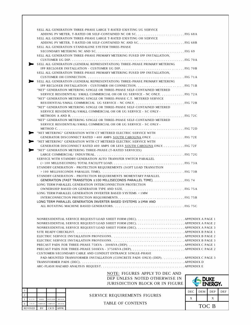
SERVICE REQUIREMENTS FIGURES
TABLE OF CONTENTS0
APPR.CK'DBYREVISED
SELL ALL GENERATION THREE-PHASE PRIMARY METERING FUSED IPP INSTALLATION,
CUSTOMER UG DIP FIG 70A
SELL ALL GENERATION THREE-PHASE PRIMARY METERING FUSED IPP INSTALLATION,
CUSTOMER OH CONNECTION
FIG 70B
SELL ALL GENERATION (GENERAL REPRESENTATION) THREE-PHASE PRIMARY METERING
IPP RECLOSER INSTALLATION - CUSTOMER UG DIP
FIG 71A
SELL ALL GENERATION (GENERAL REPRESENTATION) THREE-PHASE PRIMARY METERING
IPP RECLOSER INSTALLATION - CUSTOMER OH CONNECTION FIG 71B
"NET" GENERATION METERING SINGLE OR THREE-PHASE SELF-CONTAINED METERED
SERVICE RESIDENTIAL/ SMALL COMMERCIAL OH OR UG SERVICE - NC ONLY FIG 72A
"NET" GENERATION METERING SINGLE OR THREE-PHASE C.T. METERED SERVICE
RESIDENTIAL/SMALL COMMERCIAL UG SERVICE - NC ONLY FIG 72B
FIG 73A
STANDBY GENERATION - PROTECTION REQUIREMENTS (SOFT LOAD TRANSITION
>100 MILLISECONDS PARALLEL TIME) FIG 73B
SERVICE WITH STANDBY GENERATION AUTO TRANSFER SWITCH PARALLEL
(>100 MILLISECONDS) TOTAL FACILITY LOAD
1
2
TOC B
DEFDEP
X
DEMDEC
3
1/8/16SIMPSON SIMPSON ADCOCK
STANDBY GENERATION - PROTECTION REQUIREMENTS MOMENTARY PARALLEL
GENERATION (FAST TRANSITION ≤100 MILLISECONDS PARALLEL TIME) FIG 74
LONG TERM PARALLEL GENERATION INTERCONNECTION PROTECTION
OWNERSHIP BASED ON GENERATOR TYPE AND SIZE FIG 75A
LONG TERM PARALLEL GENERATION INVERTER BASED SYSTEMS <1MW
INTERCONNECTION PROTECTION REQUIREMENTS FIG 75B
LONG TERM PARALLEL GENERATION INVERTER BASED SYSTEMS ≥1MW AND
ALL ROTATING MACHINE BASED GENERATORS FIG 75C
"NET" GENERATION METERING SINGLE OR THREE-PHASE SELF-CONTAINED METERED
SERVICE RESIDENTIAL/SMALL COMMERCIAL OH OR UG SERVICE - SC ONLY -
FIG 72CMETHODS A AND B
"NET" GENERATION METERING SINGLE OR THREE-PHASE SELF-CONTAINED METERED
SERVICE RESIDENTIAL/SMALL COMMERCIAL OH OR UG SERVICE - SC ONLY -
FIG 72DMETHOD C
"NET METERING" GENERATION WITH CT METERED ELECTRIC SERVICE WITH
GENERATOR DISCONNECT RATED >400 AMPS SOUTH CAROLINA ONLY FIG 72E
X
NOTE: FIGURES APPLY TO DEC AND
DEP UNLESS NOTED OTHERWISE IN
JURISDICTION BLOCK OR IN FIGURE
NONRESIDENTIAL SERVICE REQUEST/LOAD SHEET FORM (DEC) APPENDIX A PAGE 1
SITE READY CHECKLIST APPENDIX B PAGE 1
ELECTRIC SERVICE INSTALLATION PROVISIONS APPENDIX B PAGE 2
ELECTRIC SERVICE INSTALLATION PROVISIONS APPENDIX B PAGE 3
PRECAST PADS FOR THREE-PHASE 75KVA - 300KVA (DEP) APPENDIX C PAGE 1
NONRESIDENTIAL SERVICE REQUEST/LOAD SHEET FORM (DEC) APPENDIX A PAGE 2
NONRESIDENTIAL SERVICE REQUEST/LOAD SHEET FORM (DEC) APPENDIX A PAGE 3
PRECAST PADS FOR THREE-PHASE 500KVA - 3750KVA (DEP) APPENDIX C PAGE 2
CUSTOMER/SECONDARY CABLE AND CONDUIT ENTRANCE SINGLE-PHASE
APPENDIX C PAGE 3
TRANSFORMER PADS (DEC) APPENDIX D
ARC-FLASH HAZARD ANALYSIS REQUEST APPENDIX E
PAD-MOUNTED TRANSFORMER INSTALLATION (CONCRETE PADS ONLY) (DEP)
SELL ALL GENERATION THREE-PHASE LARGE T-RATED EXISTING UG SERVICE
ADDING PV METER, T-RATED OR SELF-CONTAINED NC OR SC FIG 68A
SELL ALL GENERATION STANDALONE SYSTEM THREE-PHASE
SECONDARY METERING NC AND SC FIG 69
SELL ALL GENERATION THREE-PHASE LARGE T-RATED EXISTING OH SERVICE
ADDING PV METER, T-RATED OR SELF-CONTAINED NC AND SC FIG 68B
8/3/16EANES FLETCHER ADCOCK
"NET METERING" GENERATION WITH CT METERED ELECTRIC SERVICE WITH
GENERATOR DISCONNECT RATED 400 AMPS OR LESS SOUTH CAROLINA ONLY FIG 72F
"NET" GENERATION METERING THREE-PHASE (T-RATED SERVICES)
LARGE COMMERCIAL/ INDUSTRIAL FIG 72G

1/13/16
SIMPSON EANES ADCOCK
CONSTRUCTION/TEMPORARY SERVICE POLE
FOR URD AREAS0
APPR.CK'DBYREVISED
GROUNDING
TREATED
POST OR
POLE
ADEQUATE
TO
SUPPORT
LOAD
NOTES:
1. CUSTOMER FURNISHES ALL ITEMS EXCEPT METER. INSTALLATION IS TO BE MADE BY ELECTRICIAN TO MEET
N.E.C. AND LOCAL ORDINANCES.
3' TO 6'
18" PER
24" MIN.
36" MIN.
TRANSFORMER
2' FT. OR LESS
STREET
STREET
TEMP CABLE
MARKER OR
SIDE VIEW
SIDE VIEW
STREET
TRANSFORMER, PEDESTAL
OR CABLE MARKER
2 FT. OR LESS
TEMPORARY
SERVICE BOARD
PROPERTY LINE
PLAN VIEW
PEDESTAL
CONSTRUCTION
METER BASE/
DISCONNECT
UNIT
RIGID CONDUIT
PER N.E.C.
SERVICE POLE
CONSTRUCTION
METER BASE/
DISCONNECT
UNIT
SERVICE POLE
CONDUCTOR ENDS TO BE CAPPED TO PREVENT WATER ENTRY.
2. CUSTOMER'S ELECTRICIAN TO SUPPLY SUITABLE CONDUCTORS (SEPARATE CONDUCTORS - NO SHEATHED
2' FT. OR LESS
SEE
NOTE 2
SEE NOTE 3
3. CONDUIT TO BE INSTALLED IN DESIGNATED SPACE IN PANEL AS REQUIRED BY N.E.C. 230.7.
N.E.C. 300.5(D)(1)
6
CABLES!) FROM SOURCE SIDE LUGS OF METER BASE TO 5' MINIMUM BEYOND END OF CONDUIT RISER.
7
ELECTRODE
PER N.E.C.
8
FIG 1A
DEFDEP
X
DEMDEC
4. TYPICAL SERVICE IS 120/240V SINGLE-PHASE 10KW MAXIMUM.

TEMPORARY UNDERGROUND CONSTRUCTION
SINGLE-PHASE SERVICE POST0
APPR.CK'DBYREVISED
1
2
3
FIG 1B
DEFDEP
X
DEMDEC
2/12/16
SIMPSON EANES ADCOCK
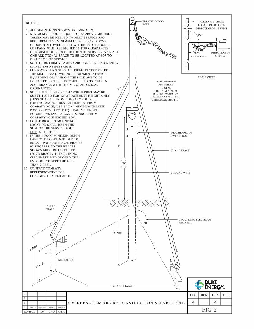
2" X 4" STAKES
4' MIN.
6'
6'
GROUND WIRE
2" X 4" BRACE
12'-0" MINIMUM
ANYWHERE
IN SPAN
IF OVER ROADS OR
AREAS SUBJECT TO
VEHICULAR TRAFFIC)
WEATHERPROOF
SWITCH BOX
TREATED WOOD
POLE
8'
3'-0"
TO
2" X 4"
NOTES:
1. ALL DIMENSIONS SHOWN ARE MINIMUM.
2. MINIMUM 20' POLE REQUIRED (16' ABOVE GROUND).
TALLER MAY BE NEEDED TO MEET SERVICE SAG
REQUIREMENTS. MINIMUM 16' POLE (12' ABOVE
3. ONE BRACE TO BE IN DIRECTION OF SERVICE. AT LEAST
ONE ADDITIONAL BRACE TO BE LOCATED AT 90° TO
DIRECTION OF SERVICE.
4. SOIL TO BE FIRMLY TAMPED AROUND POLE AND STAKES
DRIVEN INTO FIRM EARTH.
5. CUSTOMER FURNISHES ALL ITEMS EXCEPT METER.
THE METER BASE, WIRING, EQUIPMENT SERVICE,
EQUIPMENT GROUND ON THE POLE ARE TO BE
INSTALLED BY THE CUSTOMER'S ELECTRICIAN IN
ACCORDANCE WITH THE N.E.C. AND LOCAL
ORDINANCES.
6. SOLID, ONE PIECE, 4" X 4" WOOD POST MAY BE
SUBSTITUTED FOR 12' ATTACHMENT HEIGHT ONLY
(LESS THAN 10' FROM COMPANY POLE).
8. HOUSE BRACKET MOUNTING
LOCATION SHALL BE IN THE
SIDE OF THE SERVICE POLE
NOT IN THE TOP.
GROUNDING ELECTRODE
PER N.E.C.
6'-0"
BRACE
SEE NOTE 3
90°
PLAN VIEW
SEE NOTE 9
90°
ALTERNATE BRACE
LOCATION 90° FROM
DIRECTION OF SERVICE
DIRECTION OF
SERVICE
OVERHEAD TEMPORARY CONSTRUCTION SERVICE POLE
(18'-0" MINIMUM
9. IF THE 4 FOOT MINIMUM DEPTH
CANNOT BE OBTAINED DUE TO
ROCK, TWO ADDITIONAL BRACES
90 DEGREES TO THE BRACES
SHOWN MUST BE INSTALLED
(FOUR BRACES TOTAL). IN NO
CIRCUMSTANCES SHOULD THE
EMBEDMENT DEPTH BE LESS
THAN 2 FEET.
0
APPR.REVISED BY CK'D
10. CONTACT COMPANY
REPRESENTATIVE FOR
CHARGES, IF APPLICABLE.
1
FIG 2
DEFDEP
X
DEMDEC
2
GROUND) ALLOWED IF SET WITHIN 10' OF SOURCE
COMPANY POLE. SEE FIGURE 11 FOR CLEARANCES.
X
SIMPSON
11/20/15
3
ADCOCKEANES
7. FOR DISTANCES GREATER THAN 10' FROM
COMPANY POLE, USE 6" X 6" MINIMUM TREATED
POST OR WOOD POLE EQUIVALENT. UNDER
NO CIRCUMSTANCES CAN DISTANCE FROM
COMPANY POLE EXCEED 100'.

METERING ENCLOSURE LABELING
ON A SINGLE PREMISE0
2
1
APPR.REVISED BY CK'D
1-1/2" MINIMUM
3/4" MINIMUM
MINIMUM 1/16" THICK
MINIMUM 1/2" HIGH LETTERS
NOTES:
1. ON INSTALLATIONS, REPAIRS, REPLACEMENTS OR UPGRADES OF ENCLOSURES INVOLVING MORE THAN ONE
OUTSIDE BY A NONFERROUS METAL OR PLASTIC PLATE ENGRAVED OR STAMPED WITH THE APARTMENT
NUMBER, OFFICE SUITE, LOT NUMBER, ETC.
2. THE PLATE SHALL BE PERMANENTLY ATTACHED TO THE METER ENCLOSURE UTILIZING AN INDUSTRIAL-STRENGTH
3. THE INSIDE OF EACH METER ENCLOSURE SHALL BE CORRECTLY IDENTIFIED WITH A PLATE DESCRIBED ABOVE
OR WITH A PERMANENT MARKER.
METER ON A SINGLE PREMISE, THE CUSTOMER SHALL CORRECTLY IDENTIFY EACH METER ENCLOSURE ON THE
FIG 3
DEFDEP
X
DEMDEC
ADHESIVE SUITABLE FOR EXTERIOR USE. TWO-SIDED TAPE IS NOT ACCEPTABLE.
X
3
10/28/15SIMPSON CHANDLEREANES
X
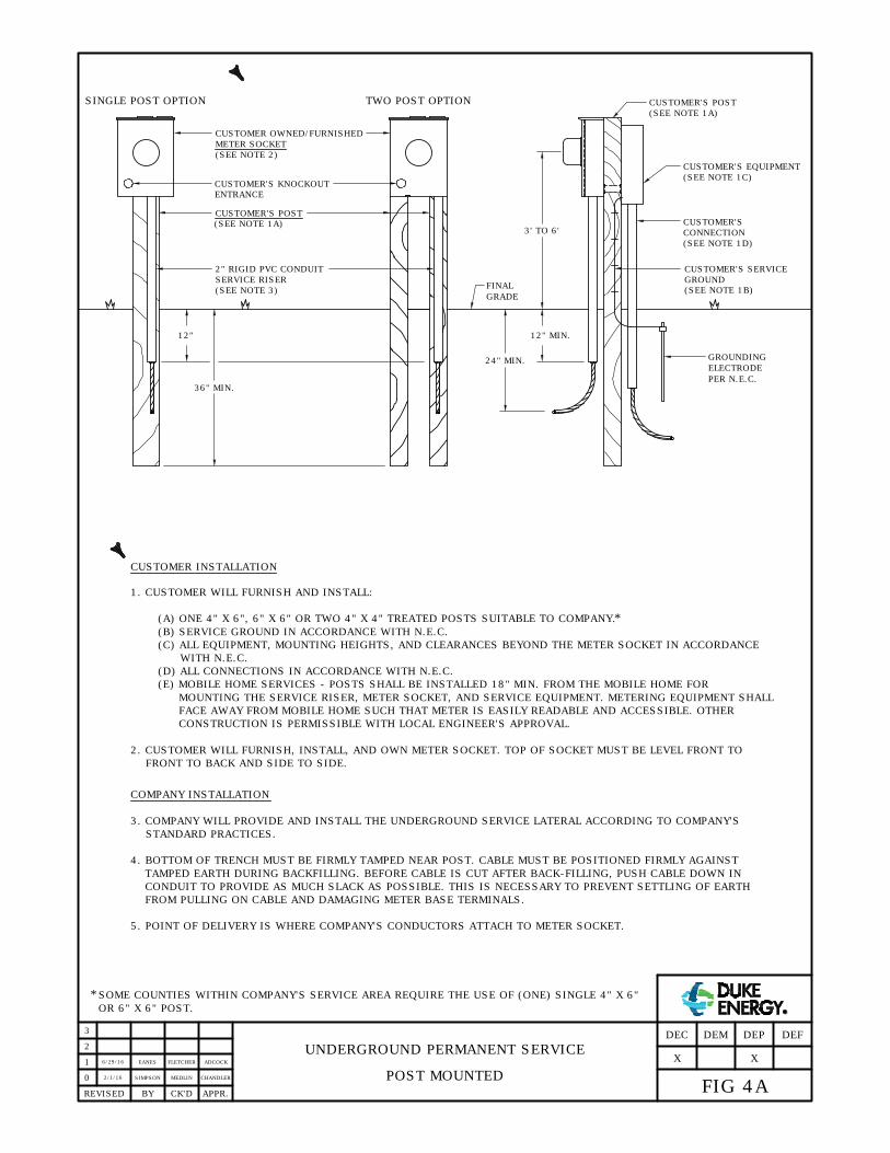
CUSTOMER INSTALLATION
1. CUSTOMER WILL FURNISH AND INSTALL:
(A) ONE 4" X 6", 6" X 6" OR TWO 4" X 4" TREATED POSTS SUITABLE TO COMPANY.
(B) SERVICE GROUND IN ACCORDANCE WITH N.E.C.
(C) ALL EQUIPMENT, MOUNTING HEIGHTS, AND CLEARANCES BEYOND THE METER SOCKET IN ACCORDANCE
(D) ALL CONNECTIONS IN ACCORDANCE WITH N.E.C.
COMPANY INSTALLATION
3. COMPANY WILL PROVIDE AND INSTALL THE UNDERGROUND SERVICE LATERAL ACCORDING TO COMPANY'S
STANDARD PRACTICES.
4. BOTTOM OF TRENCH MUST BE FIRMLY TAMPED NEAR POST. CABLE MUST BE POSITIONED FIRMLY AGAINST
TAMPED EARTH DURING BACKFILLING. BEFORE CABLE IS CUT AFTER BACK-FILLING, PUSH CABLE DOWN IN
CONDUIT TO PROVIDE AS MUCH SLACK AS POSSIBLE. THIS IS NECESSARY TO PREVENT SETTLING OF EARTH
FROM PULLING ON CABLE AND DAMAGING METER BASE TERMINALS.
5. POINT OF DELIVERY IS WHERE COMPANY'S CONDUCTORS ATTACH TO METER SOCKET.
36" MIN.
METER SOCKET
(SEE NOTE 2)
2" RIGID PVC CONDUIT
SERVICE RISER
FINAL
12" MIN.
CUSTOMER'S POST
(SEE NOTE 1A)
CONNECTION
(SEE NOTE 1D)
CUSTOMER'S SERVICE
GROUND
(SEE NOTE 1B)
CUSTOMER'S
CUSTOMER'S EQUIPMENT
SOME COUNTIES WITHIN COMPANY'S SERVICE AREA REQUIRE THE USE OF (ONE) SINGLE 4" X 6"
(SEE NOTE 1C)
WITH N.E.C.
*
ENTRANCE
CUSTOMER'S KNOCKOUT
2. CUSTOMER WILL FURNISH, INSTALL, AND OWN METER SOCKET. TOP OF SOCKET MUST BE LEVEL FRONT TO
FRONT TO BACK AND SIDE TO SIDE.
CUSTOMER OWNED/FURNISHED
*
24" MIN.
(SEE NOTE 3)
3' TO 6'
UNDERGROUND PERMANENT SERVICE
POST MOUNTED0
1
APPR.REVISED BY CK'D
12"
2
3
FIG 4A
DEFDEP
X
DEMDEC
(E) MOBILE HOME SERVICES - POSTS SHALL BE INSTALLED 18" MIN. FROM THE MOBILE HOME FOR
MOUNTING THE SERVICE RISER, METER SOCKET, AND SERVICE EQUIPMENT. METERING EQUIPMENT SHALL
FACE AWAY FROM MOBILE HOME SUCH THAT METER IS EASILY READABLE AND ACCESSIBLE. OTHER
CONSTRUCTION IS PERMISSIBLE WITH LOCAL ENGINEER'S APPROVAL.
OR 6" X 6" POST.
X
2/1/16
CHANDLERSIMPSON MEDLIN
ELECTRODE
PER N.E.C.
GROUNDING
CUSTOMER'S POST
(SEE NOTE 1A)
6/29/16
ADCOCKEANES FLETCHER
GRADE
SINGLE POST OPTION TWO POST OPTION

CUSTOMER INSTALLATION
1. CUSTOMER WILL FURNISH AND INSTALL:
(A) H FRAME POSTS CAN BE 2-3/8" PIPE OR LARGER WITH END CAPS, 2" (OD) OR LARGER TUBING WITH END
(B) SERVICE GROUND IN ACCORDANCE WITH N.E.C.
(C) ALL EQUIPMENT, MOUNTING HEIGHTS, AND CLEARANCES BEYOND THE METER SOCKET IN ACCORDANCE
(D) ALL CONNECTIONS IN ACCORDANCE WITH N.E.C.
COMPANY INSTALLATION
3. COMPANY WILL PROVIDE AND INSTALL THE UNDERGROUND SERVICE LATERAL ACCORDING TO COMPANY'S
STANDARD PRACTICES.
4. BOTTOM OF TRENCH MUST BE FIRMLY TAMPED NEAR H-FRAME. CABLE MUST BE POSITIONED FIRMLY AGAINST
TAMPED EARTH DURING BACKFILLING. BEFORE CABLE IS CUT AFTER BACK-FILLING, PUSH CABLE DOWN IN
CONDUIT TO PROVIDE AS MUCH SLACK AS POSSIBLE. THIS IS NECESSARY TO PREVENT SETTLING OF EARTH
FROM PULLING ON CABLE AND DAMAGING METER BASE TERMINALS.
5. POINT OF DELIVERY IS WHERE COMPANY'S CONDUCTORS ATTACH TO METER SOCKET.
WITH N.E.C.
2. CUSTOMER WILL FURNISH, INSTALL, AND OWN METER SOCKET. TOP OF SOCKET MUST BE LEVEL FRONT TO
FRONT TO BACK AND SIDE TO SIDE.
UNDERGROUND PERMANENT SERVICE
H FRAME STRUCTURE MOUNTED0
1
APPR.REVISED BY CK'D
2
3
FIG 4B
DEFDEP
X
DEMDEC
(E) MOBILE HOME SERVICES - H FRAME SHOULD BE INSTALLED 18" MIN. FROM THE MOBILE HOME FOR
MOUNTING THE SERVICE RISER, METER SOCKET, AND SERVICE EQUIPMENT. METERING EQUIPMENT SHALL
FACE AWAY FROM MOBILE HOME SUCH THAT METER IS EASILY READABLE AND ACCESSIBLE. OTHER
CONSTRUCTION IS PERMISSIBLE WITH LOCAL ENGINEER'S APPROVAL.
X
CAPS, OR 2" OR LARGER CHANNEL, OR EQUIVALENT, ALL GALVANIZED, ZINC PLATED, OR ALUMINUM.
3' - 6'
METER ENCLOSURE
200 OR 320 AMP;
SEE NOTE 2
BREAKER BOX,
DISCONNECT, ETC.
UNISTRUT, OR ALUMINUM, GALVANIZED,
OR ZINC PLATED STEEL ANGLE OR
CHANNEL, 1-1/2" MINIMUM.
SEE NOTE 1(A).
ATTACH USING U-BOLTS WITH NUTS
AND LOCK WASHERS OR BOLTS THROUGH
DRILLED HOLE WITH NUTS AND LOCK
WASHERS, ALL GALVANIZED OR ZINC
PLATED, OR BY WELDING.
PROVIDE SUPPORT PIECE WHERE METER
HEIGHT IS MORE THAN 5'.
TAMP AND FIRM UP SOIL
AROUND POSTS.
ATTACH WITH
PVC CLAMP
SERVICE CONDUIT
RISER
ELECTRODE
PER N.E.C.
GROUNDING
12"
36"
ATTACH WITH
GALVANIZED STRAP
OR SIMILAR
10/6/15
CHANDLERSIMPSON MEDLIN
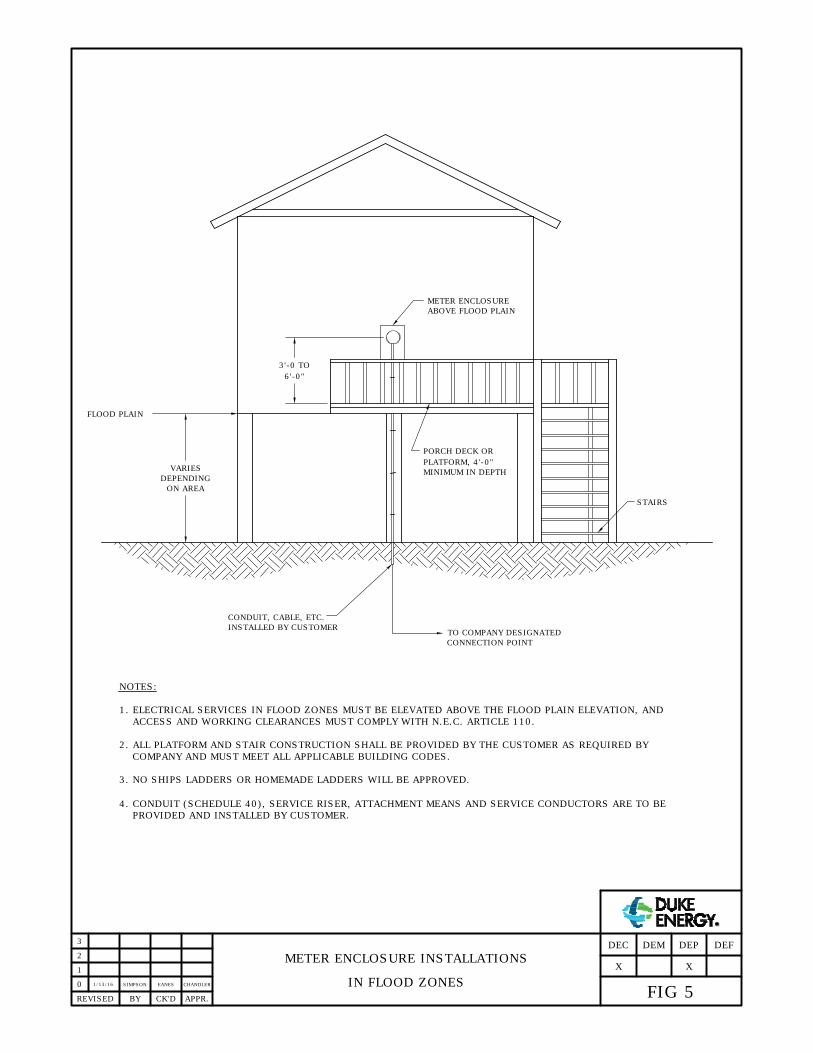
METER ENCLOSURE INSTALLATIONS
IN FLOOD ZONES
NOTES:
FLOOD PLAIN
VARIES
DEPENDING
ON AREA
CONDUIT, CABLE, ETC.
INSTALLED BY CUSTOMER
STAIRS
TO COMPANY DESIGNATED
CONNECTION POINT
METER ENCLOSURE
ABOVE FLOOD PLAIN
PORCH DECK OR
PLATFORM, 4'-0"
MINIMUM IN DEPTH
3'-0 TO
6'-0"
0
APPR.REVISED BY CK'D
1. ELECTRICAL SERVICES IN FLOOD ZONES MUST BE ELEVATED ABOVE THE FLOOD PLAIN ELEVATION, AND
ACCESS AND WORKING CLEARANCES MUST COMPLY WITH N.E.C. ARTICLE 110.
2. ALL PLATFORM AND STAIR CONSTRUCTION SHALL BE PROVIDED BY THE CUSTOMER AS REQUIRED BY
COMPANY AND MUST MEET ALL APPLICABLE BUILDING CODES.
3. NO SHIPS LADDERS OR HOMEMADE LADDERS WILL BE APPROVED.
1
2
FIG 5
DEFDEP
X
DEMDEC
X
3
1/13/16SIMPSON EANES CHANDLER
4. CONDUIT (SCHEDULE 40), SERVICE RISER, ATTACHMENT MEANS AND SERVICE CONDUCTORS ARE TO BE
PROVIDED AND INSTALLED BY CUSTOMER.

1/19/16
SIMPSON EANES ADCOCK
RESIDENTIAL PERMANENT OVERHEAD
0
2
1
APPR.REVISED BY CK'D
3
FIG 8
DEFDEPDEMDEC
X
THRU-THE-ROOF MAST INSTALLATION
WEATHERHEAD
RISER
GALVANIZED
STRAPS
METER ENCLOSURE
HUB
200 OR 320 AMP
METER ENCLOSURE
PROVIDED AND
INSTALLED BY
CUSTOMER
3'-6'
FINAL GRADE
GROUND WIRE
SEE NOTE 2
DRIP LOOP
REQUIRED
SERVICE
ENTRANCE CABLE
DUKE ENERGY
SERVICE DROP
ATTACHMENT POINT PROVIDED
AND INSTALLED BY CUSTOMER
GROUNDING ELECTRODE
PER N.E.C. BY CUSTOMER
GALVANIZED RIGID STEEL CONDUIT 2" MINIMUM
FURNISHED AND INSTALLED BY CUSTOMER.
P.O.D.
BRACKET AND SERVICE DROP
FURNISHED AND INSTALLED
BY DUKE ENERGY
PLACE MOUNTING BRACKET
AS HIGH AS POSSIBLE.
PLACE MOUNTING BRACKET CLOSE
TO ADAPTER OR METER BASE. ADAPTER
IS NOT REQUIRED IN ALL APPLICATIONS.
METER ENCLOSURE PROVIDED AND
3'-6'
INSTALLED BY CUSTOMER
X
NOTES:
1. SEE FIGURE 14A FOR METER ENCLOSURE GROUNDING DETAILS.
2. SEE FIGURES 10 AND 11 FOR SERVICE DROP CLEARANCES.
3. CUSTOMER PROVIDES AND INSTALLS ALL ITEMS EXCEPT METER AND SERVICE DROP, EXCEPT AS NOTED
ABOVE.
4. THRU-THE-ROOF RISERS MUST BE ACCESSIBLE TO A COMPANY BUCKET TRUCK OR A COMPANY EMPLOYEE ON
AN EXTENSION LADDER NOT TO EXCEED 25' ABOVE GRADE.
5. RISERS IN EXCESS OF 72" ABOVE ROOF LINES SHALL BE ACCESSIBLE TO A COMPANY BUCKET TRUCK.
RISER ON WALL INSTALLATION

2/1/16
SIMPSON EANES ADCOCK
PERMANENT OVERHEAD SERVICE POLE
0
2
1
APPR.REVISED BY CK'D
3
FIG 9A
DEFDEP
X
DEMDEC
X
POINT OF DELIVERY
GROUND WIRE
ATTACHMENT POINT
DUKE ENERGY
SERVICE CABLE
WEATHERHEAD
6" X 6" PRESSURE TREATED TIMBER
OR PRESSURE TREATED POLE PER
FIGURE 9B.
"B"
3' - 6'
TYPICAL GROUNDING
ELECTRODE PER N.E.C.
UPPER END OF GROUND ROD
SHALL BE FLUSH WITH OR
BELOW FINAL GRADE UNLESS
THE ROD END AND GROUND
CONDUCTOR ATTACHMENT ARE
PROTECTED AGAINST PHYSICAL
DAMAGE.
(SEE FIG 14A)
POLE DEPTH
"A"
FINAL GRADE
"C"
UP TO 320 AMP
METER ENCLOSURE
CUSTOMER
PANEL PER
N.E.C.
RISER
PLAN VIEW
"S"
CUSTOMER'S
POLE
DUKE ENERGY'S
EXISTING POLE LINE
OR PROPOSED POLE LINE
*
*
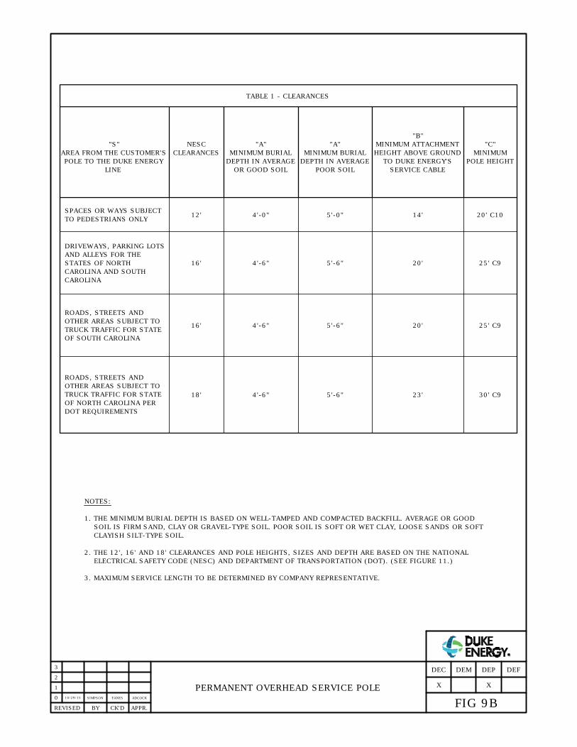
10/29/15
SIMPSON EANES ADCOCK
PERMANENT OVERHEAD SERVICE POLE
0
2
1
APPR.REVISED BY CK'D
3
FIG 9B
DEFDEP
X
DEMDEC
X
NOTES:
1. THE MINIMUM BURIAL DEPTH IS BASED ON WELL-TAMPED AND COMPACTED BACKFILL. AVERAGE OR GOOD
SOIL IS FIRM SAND, CLAY OR GRAVEL-TYPE SOIL. POOR SOIL IS SOFT OR WET CLAY, LOOSE SANDS OR SOFT
CLAYISH SILT-TYPE SOIL.
2. THE 12', 16' AND 18' CLEARANCES AND POLE HEIGHTS, SIZES AND DEPTH ARE BASED ON THE NATIONAL
ELECTRICAL SAFETY CODE (NESC) AND DEPARTMENT OF TRANSPORTATION (DOT). (SEE FIGURE 11.)
3. MAXIMUM SERVICE LENGTH TO BE DETERMINED BY COMPANY REPRESENTATIVE.
TABLE 1 - CLEARANCES
NESC
CLEARANCES
"S"
SPACES OR WAYS SUBJECT
TO PEDESTRIANS ONLY
DRIVEWAYS, PARKING LOTS
AND ALLEYS FOR THE
STATES OF NORTH
CAROLINA AND SOUTH
ROADS, STREETS AND
OTHER AREAS SUBJECT TO
TRUCK TRAFFIC FOR STATE
OF SOUTH CAROLINA
ROADS, STREETS AND
OTHER AREAS SUBJECT TO
TRUCK TRAFFIC FOR STATE
OF NORTH CAROLINA PER
DOT REQUIREMENTS
12'
16'
16'
18'
DEPTH IN AVERAGE
OR GOOD SOIL
MINIMUM BURIAL
DEPTH IN AVERAGE
POOR SOIL
MINIMUM BURIAL
TO DUKE ENERGY'S
SERVICE CABLE
HEIGHT ABOVE GROUND
MINIMUM ATTACHMENT"A" "A"
"B"
POLE HEIGHT
MINIMUM
"C"
4'-0"
4'-6"
4'-6"
4'-6"
5'-0"
5'-6"
5'-6"
5'-6"
14'
20'
20'
23'
20' C10
25' C9
25' C9
30' C9
POLE TO THE DUKE ENERGY
LINE
AREA FROM THE CUSTOMER'S
CAROLINA

O
V
E
R
H
A
N
G
C
B
CLEARANCES OVER ROOF
A. AT SERVICE MAST
B. NOT AT OVERHANG
C. AT OVERHANG
1. VERTICAL CLEARANCES OF NEW SERVICES TO BUILDINGS AT LOCATIONS A, B, AND C AS SHOWN ABOVE
MUST MEET THE FOLLOWING MINIMUM CLEARANCES FOR THE HIGHEST VOLTAGE BETWEEN ANY TWO
CONDUCTORS.
2. A ROOF IS CONSIDERED READILY ACCESSIBLE WHEN ACCESS IS THRU A DOORWAY, RAMP, STAIRWAY, OR
PERMANENTLY MOUNTED LADDER. A SLOPED ROOF IS ONE WHERE ROOF RISES 4" OR MORE IN 12" OF
HORIZONTAL DISTANCE.
3. SERVICES MUST NOT BE INSTALLED WITHOUT SPECIFICATION CLEARANCES. FOR INSTALLATIONS SIMILAR
TO SKETCH, SERVICE MAST SHOULD BE TALLER AND STRONGER, OR LOCATED NEAR CORNER. IF PRACTICAL,
SERVICE SHOULD BE ATTACHED ON SIDE OF BUILDING WHERE IT DOES NOT CROSS THE ROOF.
4. SERVICES SHALL ALSO HAVE 3' CLEARANCE IN ANY DIRECTION FROM WINDOWS, DOORS, PORCHES, OR
SIMILAR LOCATIONS. THIS DOES NOT APPLY TO MULTIPLEX CONDUCTORS ABOVE THE TOP LEVEL OF A
WINDOW OR TO WINDOWS NOT DESIGNED TO OPEN. PER N.E.S.C. RULE 234.
5. POINT OF ATTACHMENT OF SERVICE TO BUILDING SHALL BE HIGH ENOUGH TO PROVIDE THE GROUND
SHALL NOT REQUIRE THE USE OF A LADDER ON CARPORT OR OTHER ROOF.
CLEARANCES PER FIGURE 11, BUT SHALL NOT EXCEED 25' ABOVE GRADE AT TIME OF INSTALLATION AND
LOCATION
60° FINAL SAG
MIN. AT
0-300V 300-600V
36"
18"
10'
10'
10'
10'A OR B
A OR B
C
OVER OVERHANG PORTION OF ROOF (NO MORE THAN 4'
OVER FLAT OR READILY ACCESSIBLE ROOF
OVER SLOPED ROOF WHICH IS NOT READILY ACCESSIBLE
OF CABLE)
CLEARANCES
SERVICE DROP MINIMUM CLEARANCE -
THRU-THE-ROOF SERVICE MAST
A
0
3
2
1
APPR.REVISED BY CK'D
FIG 10
DEFDEP
X
DEMDEC
X
10/28/15
SIMPSON EANES ADCOCK
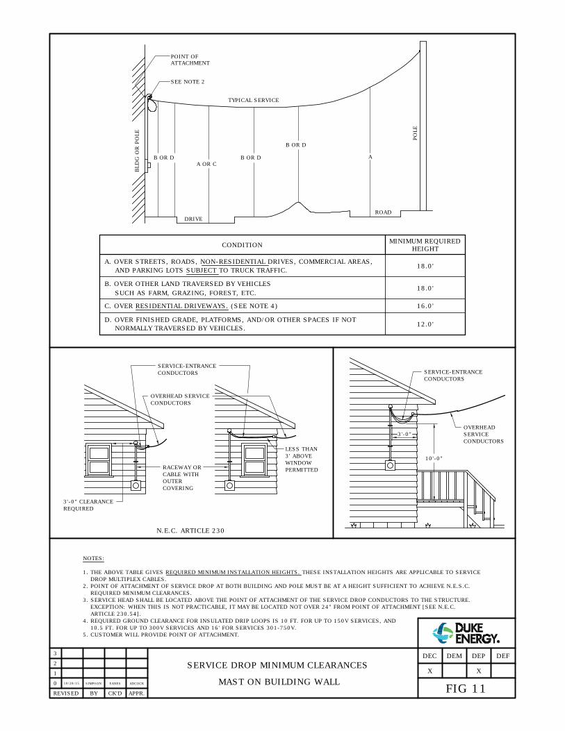
1. THE ABOVE TABLE GIVES REQUIRED MINIMUM INSTALLATION HEIGHTS. THESE INSTALLATION HEIGHTS ARE APPLICABLE TO SERVICE
C. OVER RESIDENTIAL DRIVEWAYS. (SEE NOTE 4)
D. OVER FINISHED GRADE, PLATFORMS, AND/OR OTHER SPACES IF NOT
NORMALLY TRAVERSED BY VEHICLES.
2. POINT OF ATTACHMENT OF SERVICE DROP AT BOTH BUILDING AND POLE MUST BE AT A HEIGHT SUFFICIENT TO ACHIEVE N.E.S.C.
REQUIRED MINIMUM CLEARANCES.
3. SERVICE HEAD SHALL BE LOCATED ABOVE THE POINT OF ATTACHMENT OF THE SERVICE DROP CONDUCTORS TO THE STRUCTURE.
EXCEPTION: WHEN THIS IS NOT PRACTICABLE, IT MAY BE LOCATED NOT OVER 24" FROM POINT OF ATTACHMENT [SEE N.E.C.
4. REQUIRED GROUND CLEARANCE FOR INSULATED DRIP LOOPS IS 10 FT. FOR UP TO 150V SERVICES, AND
10.5 FT. FOR UP TO 300V SERVICES AND 16' FOR SERVICES 301-750V.
NOTES:
A. OVER STREETS, ROADS, NON-RESIDENTIAL DRIVES, COMMERCIAL AREAS,
AND PARKING LOTS SUBJECT TO TRUCK TRAFFIC.
SUCH AS FARM, GRAZING, FOREST, ETC.
B. OVER OTHER LAND TRAVERSED BY VEHICLES
BLD
G O
R PO
LE
DRIVE
A OR C
SEE NOTE 2
ATTACHMENT
POINT OF
B OR D
TYPICAL SERVICE
B OR D
ROAD
B OR D
A
PO
LE
CONDITION
18.0'
16.0'
12.0'
MINIMUM REQUIRED
HEIGHT
SERVICE DROP MINIMUM CLEARANCES
MAST ON BUILDING WALL
DROP MULTIPLEX CABLES.
0
1
APPR.REVISED BY CK'D
5. CUSTOMER WILL PROVIDE POINT OF ATTACHMENT.
SERVICE-ENTRANCE
CONDUCTORS
18.0'
3'-0" CLEARANCE
RACEWAY OR
CABLE WITH
OUTER
COVERING
OVERHEAD SERVICE
CONDUCTORS
LESS THAN
WINDOW
REQUIRED
3'-0"
10'-0"
OVERHEAD
SERVICE
CONDUCTORS
SERVICE-ENTRANCE
CONDUCTORS
N.E.C. ARTICLE 230
2
PERMITTED
3' ABOVE
3
10/28/15
EANESSIMPSON ADCOCK
FIG 11
DEFDEP
X
DEMDEC
X
ARTICLE 230.54].
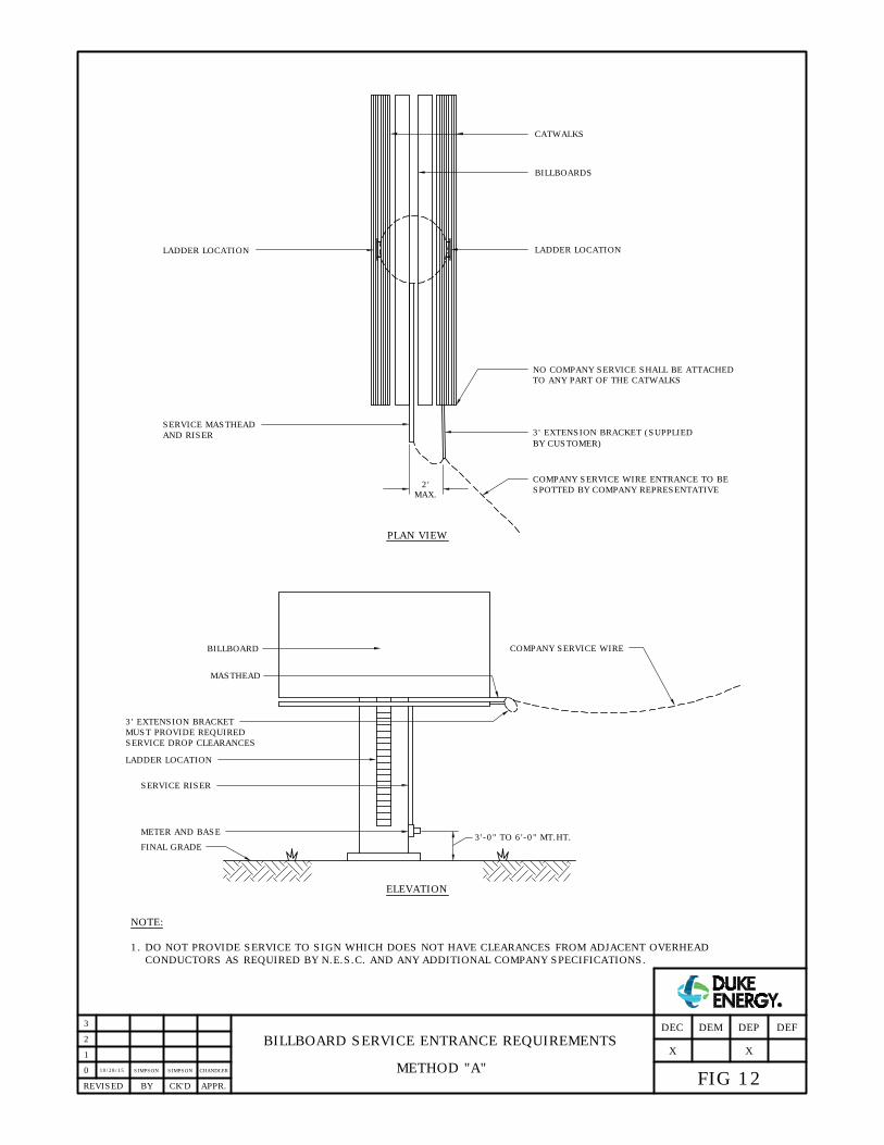
BILLBOARD COMPANY SERVICE WIRE
LADDER LOCATION
SERVICE RISER
METER AND BASE
FINAL GRADE
3'-0" TO 6'-0" MT.HT.
MASTHEAD
3' EXTENSION BRACKET
MUST PROVIDE REQUIRED
SERVICE DROP CLEARANCES
CATWALKS
BILLBOARDS
LADDER LOCATION
NO COMPANY SERVICE SHALL BE ATTACHED
LADDER LOCATION
SERVICE MASTHEAD
AND RISER
TO ANY PART OF THE CATWALKS
3' EXTENSION BRACKET (SUPPLIED
COMPANY SERVICE WIRE ENTRANCE TO BE
SPOTTED BY COMPANY REPRESENTATIVE
MAX.
NOTE:
1. DO NOT PROVIDE SERVICE TO SIGN WHICH DOES NOT HAVE CLEARANCES FROM ADJACENT OVERHEAD
CONDUCTORS AS REQUIRED BY N.E.S.C. AND ANY ADDITIONAL COMPANY SPECIFICATIONS.
BY CUSTOMER)
2'
ELEVATION
BILLBOARD SERVICE ENTRANCE REQUIREMENTS
METHOD "A"
PLAN VIEW
0
2
1
APPR.REVISED BY CK'D
FIG 12
DEFDEP
X
DEMDEC
X
3
10/28/15
SIMPSON SIMPSON CHANDLER

COMPANY SERVICE WIRE
SERVICE RISER AND MASTHEAD
STEEL POLE
OVERHEAD SERVICE WIRE MAY BE LOCATED
ANYWHERE IN THIS AREA. CALL COMPANY
REPRESENTATIVE TO DETERMINE SERVICE
3
'
M
I
N
3
'
M
I
N
NO PART OF COMPANY
SERVICE WIRE WILL
BE RUN WITHIN
3' OF LADDER
3' MIN.
BILLBOARD
COMPANY SERVICE WIRE
LADDER LOCATION
SERVICE RISER
METER AND BASE
FINAL GRADE
MT. HT.
3'-0" TO 6'-0"
ELEVATION
PLAN
BILLBOARD SERVICE ENTRANCE REQUIREMENTS
METHOD "B"0
3
2
1
APPR.REVISED BY CK'D
ENTRANCE LOCATION.
FIG 13
DEFDEP
X
DEMDEC
10/26/15
SIMPSON EANES ADCOCK
X

NATIONAL ELECTRICAL CODE (N.E.C.) ALLOWABLE
LOCATIONS OF CONNECTIONS OF GROUNDED (NEUTRAL)
CONDUCTOR AND GROUNDING ELECTRODE CONDUCTOR
OVERHEAD - SELF-CONTAINED METER BASE
IN AN ACCESSIBLE
METER ENCLOSURE
IN SERVICE
DISCONNECTING
MEANS
CUSTOMER'S
SERVICE ENTRANCE
MAIN
BKR.
UNDERGROUND - SELF-CONTAINED METER BASE
MAIN
BKR.
IN SERVICE
DISCONNECTING
MEANS
IN METER
BASE
METER
BASE
COMPANY RISER
AND SERVICE
BUILDING
UNDERGROUND - TROUGH
CUSTOMER
TROUGH
COMPANY
UG SERVICE
SERVICE
DROP
NOTE: ONLY NEUTRAL CONDUCTOR SHOWN FOR CLARITY.
METER BASE
OR
OR
OR GANG BASE OR GANG BASE
REFERENCE: N.E.C. ARTICLE 250
0
APPR.REVISED BY CK'D
CUSTOMER GROUNDING
BUSS CONNECTOR
CUSTOMER
GROUNDING BUSS
1
COMPANY
NEUTRAL
CUSTOMER - PROVIDED
AND MOUNTED INTERSYSTEM
BONDING POINT
2
COMPANY
3
TWO OPTIONS FOR GROUNDING ELECTRODE LOCATION TWO OPTIONS FOR GROUNDING ELECTRODE LOCATION
BLOCK AND
FIG 14A
DEFDEP
X
DEMDEC
P.O.D.
GROUNDING ELECTRODE
X
1/22/16
SIMPSON EANES CHANDLER
1. CUSTOMER TO INSTALL METER SOCKETS AS SPECIFIED BY THE COMPANY. DISCONNECTS MUST BE GROUPED
PER N.E.C. ARTICLES 230.71 AND 72 AND APPROVED BY THE LOCAL AHJ.
NOTES:

NATIONAL ELECTRICAL CODE (N.E.C.) ALLOWABLE
LOCATIONS OF CONNECTIONS OF GROUNDED (NEUTRAL)
CONDUCTOR AND GROUNDING ELECTRODE CONDUCTOR
REFERENCE: N.E.C. ARTICLE 250
0
APPR.REVISED BY CK'D
1
2
3
FIG 14B
DEFDEP
X
DEMDEC
CT
CUSTOMER
BONDING
COMPANY METER
ENCLOSURE
CT CABINET
JUMPER
CT CABINET INSTALLATION
PREFERRED METHOD
CT CABINET INSTALLATION
ALTERNATE METHOD
NOTE: ONLY NEUTRAL CONDUCTOR SHOWN FOR CLARITY.
REFERENCE: N.E.C. ARTICLE 250
CUSTOMER
MAIN BREAKER
GROUNDING
ELECTRODE
TO P.M.T.
M
1" RIGID METALLIC CONDUIT -
EFFECTIVELY BONDED OR
BONDING JUMPER TO CT
COMPANY NEUTRAL
AND CONNECTION
BLOCK
CT
CT
COMPANY RISER
AND SERVICE
CONDUCTOR
NEUTRAL/
GROUNDING
CT
CUSTOMER
BONDING
CT CABINET
JUMPER
MAIN BREAKER
GROUNDING
ELECTRODE
TO P.O.D.
M
PHASE WIRES RUN STRAIGHT
THRU CT'S TO MAIN BREAKER
CT
CT
CUSTOMER
SERVICE
CONDUCTORS
CUSTOMER
CUSTOMER NEUTRAL -
CONNECTED TO NEUTRAL
BUSS IN MAIN BREAKER ONLY
BUSS
NEUTRAL/
GROUNDING
BUSS
10/29/15
SIMPSON EANES CHANDLER
X
CABINET BONDING LUG
COMPANY METER
ENCLOSURE
1" RIGID METALLIC CONDUIT -
EFFECTIVELY BONDED OR
BONDING JUMPER TO CT
CABINET BONDING LUG

10/29/15
SIMPSON EANES ADCOCK
METERED SERVICE VOLTAGES
0
3
2
1
APPR.REVISED BY CK'D
FIG 15
DEFDEP
X
DEMDEC
X
METERED SERVICE VOLTAGES
120V, 2-WIRE
120/208V, 3-WIRE
120/240V, 3-WIRE
4160Y/2400V, 4-WIRE
12470V, 3-WIRE
12470Y/7200V, 4-WIRE
22860V, 3-WIRE
240/480V, 3WIRE
2400V, 2-WIRE
7200V, 2-WIRE
13200V, 2-WIRE
THREE-PHASE
208Y/120V, 4WIRE
240/120V, 4-WIRE
240V, 3-WIRE
480V, 3-WIRE
480Y/277V, 4-WIRE
480/240V, 4-WIRE
600V, 3WIRE
2400V, 3-WIRE
22860Y/13200V, 4-WIRE
*
*
METERED SERVICE VOLTAGES
120/208V, 3-WIRE
120/240V, 3-WIRE
240/480V, 3-WIRE
7200V, 2-WIRE
13800V, 2-WIRE
14400V, 2-WIRE
THREE-PHASE
208Y/120V, 4-WIRE
240V, 3-WIRE
460V, 3-WIRE
460Y/265V, 4-WIRE
480V, 3-WIRE
480Y/277V, 4-WIRE
575V, 3-WIRE
2300V, 3-WIRE
4160Y/2400V, 4-WIRE
12470Y/7200V, 4-WIRE
23900Y/13800V, 4-WIRE
24940Y/14400V, 4-WIRE
SINGLE-PHASE SINGLE-PHASE
*
*
*
*
**
*
*
*
NON-STANDARD VOLTAGES THAT MAY BE SUPPLIED UNDER CERTAIN CIRCUMSTANCES
FROM OVERHEAD TRANSFORMER BANK ONLY
1. SEE FIGURE 59 FOR CONNECTING ALL 4-WIRE Y-CONNECTED SERVICES.
*
**
2. SEE FIGURE 60 FOR CONNECTING ALL 3-WIRE DELTA-CONNECTED SERVICES
NOTES:
*
*
*
*
DEP DEC

LINE 1
120
VOLTS
120
LINE 2
VOLTS
NEUTRAL
120
LINE 1
VOLTS
NEUTRAL
2 WIRE 120 VOLT SOURCE
120
VOLTS
NEUTRAL
NEUTRAL
PREFERRED
JUMPER
120 VOLTS
LINE
METERING, SINGLE-PHASE, 120 VOLTS, 2 WIRE
REQUIRES FORM 2S METER REQUIRES FORM 1S METER
ALTERNATE
JUMPER
NOTES:
POSITION
POSITION
3 WIRE 120/240 VOLT SOURCE
STANDARD 240-VOLT
1. WHERE THE CUSTOMER'S METER BASE IS NOT WIRED AS SHOWN ON THIS DRAWING, AN ELECTRICAL
CONTRACTOR SHOULD REWIRE THE BASE AND THE COMPANY WILL INSTALL THE APPLICABLE METER.
"HOUSE-TYPE" METER
STANDARD 120-VOLT METER
(SEE NOTE 2)
2. INSTALLING A 2S METER IN A SOCKET WIRED FOR A 1S METER WILL RESULT IN APPROXIMATELY
50% METER REGISTRATION.
3. SEE FIG. 14A FOR GROUNDING DETAILS.
0
3
2
1
APPR.REVISED BY CK'D
FIG 18
DEFDEP
X
DEMDEC
CHANDLERSIMPSONSIMPSON10/28/15
X

12" MIN.
2. GROUND PER FIGURE 14A. UPPER END OF GROUND ROD SHALL BE FLUSH WITH OR BELOW FINAL GRADE,
PVC CONDUIT
1. BOTTOM OF TRENCH MUST BE FIRMLY TAMPED NEAR BUILDING TO REDUCE SETTLING. CABLE MUST BE
OFFSET-BEND
UNLESS THE ROD END AND GROUNDING CONDUCTOR ATTACHMENT ARE PROTECTED.
3. METERS MUST NOT BE LOCATED IN CARPORTS OR AREAS PLANNED FOR FUTURE EXPANSION.
CABLE PROTECTOR
4. POINT OF DELIVERY IS WHERE COMPANY RISER CONDUCTORS CONNECT TO THE LINE SIDE LUGS OF THE
CUSTOMER OWNED METER BASE.
3'-0 TO 6'-0"
TYPICAL UNDERGROUND SELF-CONTAINED SERVICE
SINGLE AND THREE-PHASE0
APPR.REVISED BY CK'D
1
2
FIG 20
DEFDEP
X
DEMDEC
X
3
11/20/15SIMPSON EANES ADCOCK
200 OR 320 AMP
METER ENCLOSURE
COMPANY METER
COMPANY RISER
COMPANY SERVICE
CONDUCTOR
NOTES:
POSITIONED FIRMLY AGAINST BOTTOM OF TRENCH DURING BACKFILLING.

TYPICAL CURRENT TRANSFORMER CABINET AND
METER ENCLOSURE INSTALLATION FOR
UNDERGROUND SERVICES
(SINGLE-PHASE AND THREE-PHASE)
0
APPR.REVISED BY CK'D
TYPICAL FIELD APPLICATION OF SELF-CONTAINED VS. CT METERING SINGLE-PHASE AND THREE-PHASE
MAIN
200A
MAIN
200A
MAIN
200A
MAIN
200A
COMPANY RISER
320 AMP METER WITH 400 AMP BASE
200 AMP SELF-CONTAINED
METER AND BASE
CT METER AND CABINET SIZED TO LOAD
M
COMPANY METER
1
2
FIG 21
DEFDEP
X
DEMDEC
3
10/28/15
SIMPSON
NOTES:
1. METER ENCLOSURE OWNED AND INSTALLED BY COMPANY.
2. CT CABINET
3. SERVICE CONDUCTORS WILL BE INSTALLED BY THE COMPANY OR CUSTOMER DEPENDING ON THE ESTABLISHED
POINT OF DELIVERY AS SPECIFIED BY COMPANY REPRESENTATIVE.
X
SEE NOTE 2
3' - 6'
SERVICE CONDUCTORS
(SEE NOTE 3)
COMPANY METER
ENCLOSURECT CABINET INSTALLED BY
CUSTOMER ON OUTSIDE
WALL OR APPROVED
STRUCTURE. SEE FIGURE
4B FOR STRUCTURE
GUIDELINES.
CUSTOMER'S
MAIN PANEL
MEDLIN CHANDLER
DEC: OWNED AND INSTALLED BY CUSTOMER. SEE FIGURE 43A.
DEP: OWNED BY COMPANY; INSTALLED BY CUSTOMER. SEE FIGURE 43B.

A B D E FC
HORIZONTAL GANGED METERING INSTALLATION
(2 - 6 METERS)
SINGLE-PHASE
0
APPR.REVISED BY CK'D
SEE NOTE 5
FINAL GRADE
SEE NOTE 2
3'-0" TO 6'-0"
2. COMPANY TO INSTALL SERVICE RISER.
3. POINT OF DELIVERY IS WHERE COMPANY CONDUCTORS
ATTACH TO GANGED TERMINAL LUGS.
NOTES:
1. APPROVED GANGED METER SOCKETS TO BE FURNISHED
AND OWNED BY CUSTOMER. ELECTRICAL CONTRACTOR TO
INSTALL ON OUTSIDE OF BUILDING WALL AND TO BOND TO
NEUTRAL.
GANGED PANEL OF GREATER AMPACITY MUST BE USED.
SOCKET GREATER THAN 200 AMP. CAPACITY, THEN A
4. IF ANY OF THE INDIVIDUAL SERVICES REQUIRE A METER
5. LABELING OF EACH METER ENCLOSURE SHALL MEET THE
REQUIREMENTS OF FIGURE 3.
6. SEE FIG. 14A FOR GROUNDING DETAILS.
1
2
FIG 25
DEFDEP
X
DEMDEC
X
3
1/5/15
SIMPSON EANES CHANDLER

VERTICAL GANGED METERING INSTALLATION
(2 - 6 METERS)
SINGLE-PHASE
0
APPR.REVISED BY CK'D
SEE NOTE 2
FINAL GRADE
A B
C D
E F
USE THIS PANEL ONLY WHEN MOUNTING SPACE
PROHIBITS USE OF HORIZONTAL TYPE
6'-0"
GRADE
TO FINAL
MAXIMUM
3'-0" MIN.
GRADE
TO FINAL
SEE NOTE 5
NOTES:
TO GANGED TERMINAL LUGS.
3. POINT OF DELIVERY IS WHERE COMPANY CONDUCTORS ATTACHED
2. COMPANY TO INSTALL SERVICE RISER.
1. APPROVED METER SOCKETS TO BE FURNISHED AND OWNED BY
THE CUSTOMER. ELECTRICAL CONTRACTOR TO INSTALL ON THE
THE OUTSIDE OF THE BUILDING WALL AND TO BOND TO NEUTRAL.
GREATER AMPACITY MUST BE USED.
GREATER THAN 200 AMP. CAPACITY, THEN A GANGED PANEL OF
4. IF ANY OF THE INDIVIDUAL SERVICES REQUIRE A METER SOCKET
5. LABELING OF EACH METER ENCLOSURE SHALL MEET THE
REQUIREMENTS OF FIGURE 3.
6. SEE FIG. 14A FOR GROUNDING DETAILS.
1
2
FIG 26
DEFDEP
X
DEMDEC
X
3
1/5/16
SIMPSON EANES CHANDLER

METER CENTER INSTALLATION
(MAIN DISCONNECT - GREATER THAN 6 METERS)
SINGLE AND THREE-PHASE
0
APPR.REVISED BY CK'D
CUSTOMER'S
MAIN BREAKER
METER CENTER
(CUSTOMER OWNED)
TERMINAL BLOCKS
SEE NOTE 4
RISER AND SERVICE CONDUCTOR
NOTES:
1. U.L. LISTED METER CENTER TO BE FURNISHED AND OWNED BY THE CUSTOMER. ELECTRICAL CONTRACTOR
TO INSTALL ON THE OUTSIDE OF THE BUILDING WALL AND TO BOND TO NEUTRAL.
2. SERVICE RISER AND CONDUCTOR OWNERSHIP:
3. LABEL EACH SOCKET COVER AS SHOWN IN FIGURE 3.
4. POINT OF DELIVERY (P.O.D.):
OPTIONAL
SEE NOTE 3
5. SEE FIG. 14A FOR GROUNDING DETAILS.
1
2'-6" MIN.
TO GRADE
6'-0" MAX.
2
FIG 27
DEFDEP
X
DEMDEC
3
1/5/16
SIMPSON EANES CHANDLER
X
3'-0" MIN.
TO GRADE
OWNERSHIP (SEE NOTE 2)
A. SINGLE-PHASE SERVICES: THE COMPANY
B. THREE-PHASE SERVICES: THE CUSTOMER
B. THREE-PHASE SERVICES: POINT OF DELIVERY WILL BE WHERE CUSTOMER CONDUCTORS ATTACH TO
A. SINGLE-PHASE SERVICES: POINT OF DELIVERY WILL BE WHERE COMPANY CONDUCTORS ATTACH TO
MAIN DISCONNECT. IF LOCAL INSPECTION AUTHORITY OBJECTS TO COMPANY CABLES IN UL RATED
TERMINALS OF MAIN BREAKER, THE CUSTOMER WILL PROVIDE THE APPROPRIATE TERMINAL BLOCKS
OFF THE BREAKER TO ATTACH COMPANY CABLES. TERMINAL BLOCKS MUST BE SIZED 3/0-500 KCMIL AL
OR CU MINIMUM, DOUBLE LUGGED IF NECESSARY TO ACCOMMODATE COMPANY SERVICE.
SECONDARY TERMINALS OF COMPANY TRANSFORMER.

METER ENCLOSURE
(SEE NOTE 1)
NOTES:
METER ON TRANSFORMER: A SINGLE CUSTOMER SERVED FROM THE TRANSFORMER WILL BE METERED ON THE
SECONDARY BUSHING OF TRANSFORMER. COMPANY ENGINEER SHALL APPROVE THE NUMBER AND SIZE OF
METER ON OUTSIDE WALL: COMPANY OWNS AND INSTALLS UNDERGROUND SERVICE. POINT OF DELIVERY IS
WHERE COMPANY'S CONDUCTORS CONNECT TO CUSTOMER'S CONDUCTORS IN CUSTOMER PROVIDED TROUGH
4. EACH CONDUIT SHALL CONTAIN ONE SET OF SERVICE ENTRANCE CONDUCTORS: THREE-PHASE CONDUCTORS
COMPANY CONDUCTORS
TYPICAL UNDERGROUND THREE-PHASE
SERVICE ARRANGEMENTS
NON-RESIDENTIAL
CUSTOMER'S SERVICE CONDUITS AND CABLES (SEE FIGURE 58).
(SEE FIGURES 47A AND 47B).
AND ONE NEUTRAL CONDUCTOR (IF APPLICABLE).
0
APPR.REVISED BY CK'D
TRANSFORMER. CUSTOMER OWNS AND INSTALLS UNDERGROUND SERVICE. POINT OF DELIVERY IS AT
FOR PHASE AND LABELED WITH A TAG TO IDENTIFY THE LOCATION OF THE SOURCE AND LOAD ENDS OF THE
CONDUCTOR. THE LOAD END OF EACH CABLE SHALL BE LABELED TO IDENTIFY THE SOURCE. EACH SOURCE END
SHALL BE LABELED TO IDENTIFY THE LOCATION OF THE LOAD END OF THE CABLE (TROUGH NUMBER, SWITCH
PANEL NUMBER, ETC.). SEE FIGURE 3 FOR METER ENCLOSURE LABELING AND CUSTOMER CONDUCTOR
MARKING AND LABELING. SEE FIGURES 47A AND 47B FOR TROUGH WIRING DETAIL.
OWNED SERVICES ARE RUN TO THE SAME TRANSFORMER BUT ARE METERED ELSEWHERE (BUILDING
WALL OR METER ROOM). BOTH ENDS OF ALL CUSTOMER CABLES MUST BE CLEARLY AND SPECIFICALLY MARKED
1
2
3
11/20/15
SIMPSON EANES ADCOCK
FIG 28
DEFDEP
X
DEMDEC
1. SINGLE CUSTOMER:
2. MULTIPLE CUSTOMERS:
3. EXISTING CT METER ON PMT: ADDING ADDITIONAL CUSTOMERS (MULTI-TENANT METERING):
ONE SERVICE IS C.T. METERED ON THE PAD-MOUNTED TRANSFORMER AND OTHER CUSTOMER OWNED
24" MINIMUM COVER
CUSTOMER
BUILDING
MAIN
DISCONNECT
SEE NOTES
1 AND 3
TO TROUGH
CUSTOMER WIRING
TO PMT
CUSTOMER TROUGH
(SEE NOTE 2)
X

DELTA CONNECTED
TRANSFORMER BANK
MARK POWER LEG WITH ORANGE
TAPE. POWER LEG MUST BE
THE FAR RIGHT SIDE TERMINAL
IN THE METER SOCKET FOR
CORRECT METER REGISTRATION
SWITCHBOARD
OR
PANELBOARD
POWER LEG MUST BE "B"
POSITION IN CUSTOMER'S
SWITCHBOARD OR PANELBOARD
TO COMPLY WITH SECTION
408.3(E) OF THE NATIONAL
ELECTRICAL CODE.
NEU
TRAL
PO
WER
LEG
SELF-CONTAINED
METER SOCKET
208V
240V
240V
120V
120V
240V
POWER LEG
NOTES:
1. INSTALL SOCKET WITH BY-PASS HANDLE
IN THE DOWN OR OPEN POSITION.
2. THE BY-PASS HANDLE CAN BE PUT IN
THE UP OR CLOSED POSITION FOR METER
REMOVAL, TESTING, ETC.
3. THE COVER CAN BE ONLY INSTALLED AND
SEALED WITH THE BY-PASS HANDLE IN
THE DOWN POSITION.
4. THE BY-PASS HANDLES ARE A BENT TYPE
OR AN OCTAGON SHAPED REMOVABLE
SCREW TYPE. DO NOT CUT-OFF THESE
BENT OR REMOVABLE BY-PASS HANDLES.
P
O
W
E
R
LE
G
5. THIS SAME WIRING ARRANGEMENT SHOULD
BE USED IF A CUSTOMER HAS ONLY 240
VOLT THREE-PHASE LOAD. SECTION 250
OF THE N.E.C. REQUIRES THE GROUNDED
CONDUCTOR TO BE RUN TO THE
CUSTOMER'S PANELBOARD.
240/120 VOLT THREE-PHASE 4 WIRE
SELF-CONTAINED DELTA METERING0
2
1
APPR.REVISED BY CK'D
6. SEE FIG. 14A FOR GROUNDING DETAILS.
FIG 32
DEFDEP
X
DEMDEC
3
10/28/15
EANESSIMPSON CHANDLER
X

480Y/277 VOLT METERING
VT PACK FOR SERVICES
UP TO 200 AMPS
NOTES:
1. MEASURE CUSTOMER VOLTAGE ON
3. METER MUST BE INSTALLED ON THE
LOAD SIDE OF A LINE-OF-SIGHT
VT PACK GROUND
CONNECTS TO
NEUTRAL BAR
4. BASE AND VT PACK ISSUED BY
TO DISCONNECT
TO CUSTOMER'S LOAD
21" H
X
20" W
X
5 1/2" D
5. COMPANY WILL OWN AND MAINTAIN
THE METER CABINET. IF A CABINET
200 AMP DISCONNECT CAPABLE OF
PLUG
VIA HARNESS
2:1
RATIO
VT PACK
NO WIRING
VT PACK WILL
IN AREA WHERE
SHOULD BE RUN
BE INSTALLED
NEEDS TO BE REPLACED, COMPANY
REVISED CK'DBY APPR.
0
D M
VT
TO CUSTOMER PANEL
U
COMPANY WIRING
CUSTOMER TROUGH UG SERVICE1
POD
CUSTOMER WIRING
D M
VT
TO CUSTOMER PANEL
POD
CUSTOMER WIRING
SINGLE CUSTOMER - OH OR UG SERVICE2
TO CUSTOMER MAIN PANEL
POD
CUSTOMER WIRING
EXISTING CT METER ON PMT - ADDING SECOND METER3
PMT
M
EXISTING CT
METER ON PAD
U
D M
VT
TO CUSTOMER PANEL
a. POD b. POD
a. PREFERRED: CUSTOMER-OWNED WIRING FROM PANEL TO PMT
b. ALTERNATE: COMPANY-OWNED SERVICE TO ; CUSTOMER WIRING FROM TO CUST. PANEL.
D D
MODES OF SERVICE 480Y/277V 4-WIRE VT PACK (SELF-CONTAINED)
D
M
VT
CUSTOMER-OWNED
200 AMP DISCONNECT
SELF-CONTAINED
VT PACK METER
COMPANY-OWNED -
CUSTOMER INSTALLED
LEGEND
CABLE LUGS, NOT METER SOCKET
TERMINALS.
2. METER HAS A YELLOW NAMEPLATE TO
INDICATE CLASS 200, FORM 9S.
BEING LOCKED IN THE OFF POSITION
AND PROVIDE A VISIBLE OPEN. IF
THE CUSTOMER DOES NOT PLAN ON
PROVIDING A DISCONNECT, THE
STANDARD CT CABINET WILL BE USED
FOR METERING.
METERING PERSONNEL. METER BASE
HAS A UL LISTING.
WILL FURNISH THE NEW CABINET AND
UTILIZE AN ELECTRICAL CONTRACTOR
TO REPLACE THE CABINET.
6. SEE FIGURE 41 FOR APPLICATION,
INSTALLATION, AND OPERATIONS &
MANAGEMENT NOTES.
7. ALL WIRING IS CUSTOMER OWNED.
8. SEE FIG. 14A FOR GROUNDING
PMT
POD
UG
TO COMPANY
SOURCE
POD ON TERMINALS OF PMT OR OH TRANSFORMER BANK
OH BANK
1
FIG 40
DEFDEP
X
DEMDEC
2
3
9/10/15SIMPSON MEDLIN CHANDLER
DETAILS.

10/28/15
SIMPSON MEDLIN CHANDLER
DESCRIPTION:
480Y/277 VOLT METERING
VT PACK FOR SERVICES
UP TO 200 AMPS
480Y/277-VOLT, 3-PHASE, 4-WIRE SERVICES MAY NOW BE METERED USING A CLASS 200 METER AND CABINET
SUPPLIED BY COMPANY. THE CUSTOMER WILL SUPPLY AND INSTALL A DISCONNECT SWITCH AHEAD OF THE
METER. A CABINET WITH A 200 AMP, FORM 9S SOCKET AND LEVER BYPASS WILL BE SUPPLIED BY COMPANY AND
INSTALLED BY THE CUSTOMER. COMPANY WILL INSTALL A VT PACK AND A CLASS 200 TRANSFORMER RATED
METER.
APPLICATION:
1. THIS IS AN OPTIONAL METERING SYSTEM THAT IS BEST SUITED FOR 480Y/277-VOLT METERING IN
SHOPPING MALLS WHERE DISCONNECTS ARE ALREADY REQUIRED AND WHERE SPACE IS A PREMIUM. EACH
2. IN ADDITION, THIS METERING SYSTEM MAY BE USED FOR OTHER APPLICATIONS IF ALL REQUIREMENTS ARE
MET.
3. THIS PRODUCT IS ONLY APPROVED FOR THREE-PHASE, FOUR-WIRE, 480Y/277-VOLT SERVICES AND FOR A
MAXIMUM 200 AMPERE SERVICE.
4. THIS PRODUCT MAY NOT BE USED ON 3-PHASE, 3-WIRE, 480-VOLT DELTA OR FLOATING-WYE SERVICES.
5. THE CUSTOMER MUST PROVIDE A DISCONNECT ON THE SOURCE SIDE OF THE METER THAT CAN BE LOCKED
IN THE OFF POSITION.
6. THE DISCONNECT MUST BE IN LINE-OF-SIGHT OF THE METER AS IT WILL BE USED TO DE-ENERGIZE THE
METER FOR EXCHANGES, DISCONNECTS, ETC.
7. NOTIFY THE METER TECHNICIAN WHEN CABINETS ARE REQUIRED FOR A PROJECT - THERE IS A 16 WEEK
LEAD-TIME FOR LARGE ORDERS.
INSTALLATION:
1. WHEN MANY CABINETS ARE TO BE INSTALLED AT ONE LOCATION, THE CUSTOMER MUST PROVIDE A SINGLE
POINT OF CONTACT TO COORDINATE THE INSTALLATION.
2. THE CUSTOMER IS RESPONSIBLE FOR INSTALLING THE CABINET PROVIDED BY COMPANY.
3. COMPANY WILL PROVIDE THE CABINETS WITHOUT THE VT-PACKS TO THE CUSTOMER'S ELECTRICIANS FOR
INITIAL INSTALLATION.
4. COMPANY'S METER TECHNICIANS WILL INSTALL THE VT-PACKS AND THE METER.
OPERATIONS & MANAGEMENT:
1. THE SOURCE-SIDE DISCONNECT MUST BE OPENED BEFORE PERFORMING ANY WORK IN THE METER
CABINET.
NOTE: IF THE CUSTOMER DOES NOT PLAN ON PROVIDING A DISCONNECT, THE STANDARD CT CABINET
WILL BE USED FOR METERING.
2. COMPANY WILL OWN AND MAINTAIN THE METER CABINET. IF A CABINET NEEDS TO BE REPLACED, COMPANY
WILL FURNISH THE NEW CABINET AND UTILIZE AN ELECTRICAL CONTRACTOR TO REPLACE THE CABINET.
VT PACK MUST HAVE AN INDIVIDUAL DISCONNECT.
0
3
2
1
REVISED BY CK'D APPR.
NOTES:
1. SEE FIGURE 40 FOR METER CABINET AND ONE LINE INSTALLATION DIAGRAM.
FIG 41
DEFDEP
X
DEMDEC
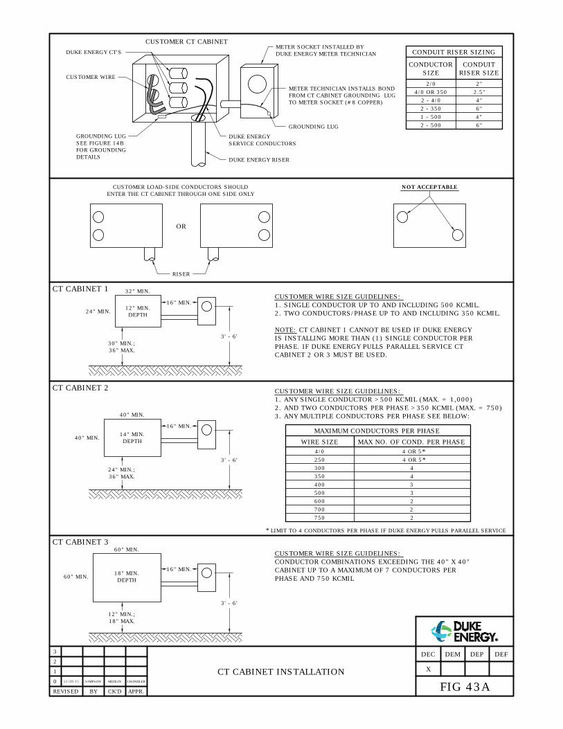
CT CABINET INSTALLATION
11/20/15
CHANDLERSIMPSON MEDLIN
REVISED BY CK'D APPR.
0
1
2
3
FIG 43A
DEFDEPDEMDEC
X
CUSTOMER CT CABINET
CUSTOMER WIRE
GROUNDING LUG
DUKE ENERGY CT'S
METER SOCKET INSTALLED BY
DUKE ENERGY METER TECHNICIAN
METER TECHNICIAN INSTALLS BOND
FROM CT CABINET GROUNDING LUG
TO METER SOCKET (#8 COPPER)
GROUNDING LUG
DUKE ENERGY
SERVICE CONDUCTORS
CONDUIT RISER SIZING
2/0
4/0 OR 350
2 - 4/0
2 - 350
1 - 500
2 - 500
2"
2.5"
4"
6"
4"
6"
RISER
OR
CUSTOMER LOAD-SIDE CONDUCTORS SHOULD
ENTER THE CT CABINET THROUGH ONE SIDE ONLY
NOT ACCEPTABLE
3' - 6'
30" MIN.;
36" MAX.
24" MIN.
12" MIN.
DEPTH
16" MIN.
CUSTOMER WIRE SIZE GUIDELINES:
1. SINGLE CONDUCTOR UP TO AND INCLUDING 500 KCMIL.
NOTE: CT CABINET 1 CANNOT BE USED IF DUKE ENERGY
IS INSTALLING MORE THAN (1) SINGLE CONDUCTOR PER
PHASE. IF DUKE ENERGY PULLS PARALLEL SERVICE CT
CABINET 2 OR 3 MUST BE USED.
CT CABINET 1
3' - 6'
24" MIN.;
36" MAX.
40" MIN.
14" MIN.
DEPTH
16" MIN.
CT CABINET 2
40" MIN.
32" MIN.
CUSTOMER WIRE SIZE GUIDELINES:
1. ANY SINGLE CONDUCTOR >500 KCMIL (MAX. = 1,000)
2. AND TWO CONDUCTORS PER PHASE >350 KCMIL (MAX. = 750)
3. ANY MULTIPLE CONDUCTORS PER PHASE SEE BELOW:
WIRE SIZE
4/0
250
300
350
400
500
4 OR 5
4 OR 5
4
4
3
3
600
700
750
2
2
2
*
*
LIMIT TO 4 CONDUCTORS PER PHASE IF DUKE ENERGY PULLS PARALLEL SERVICE*
3' - 6'
12" MIN.;
18" MAX.
60" MIN.
18" MIN.
DEPTH
16" MIN.
CT CABINET 3
60" MIN.
CUSTOMER WIRE SIZE GUIDELINES:
CONDUCTOR COMBINATIONS EXCEEDING THE 40" X 40"
CABINET UP TO A MAXIMUM OF 7 CONDUCTORS PER
PHASE AND 750 KCMIL
CONDUCTOR CONDUIT
SIZE RISER SIZE
MAXIMUM CONDUCTORS PER PHASE
MAX NO. OF COND. PER PHASE
DUKE ENERGY RISER
SEE FIGURE 14B
FOR GROUNDING
DETAILS
2. TWO CONDUCTORS/PHASE UP TO AND INCLUDING 350 KCMIL.
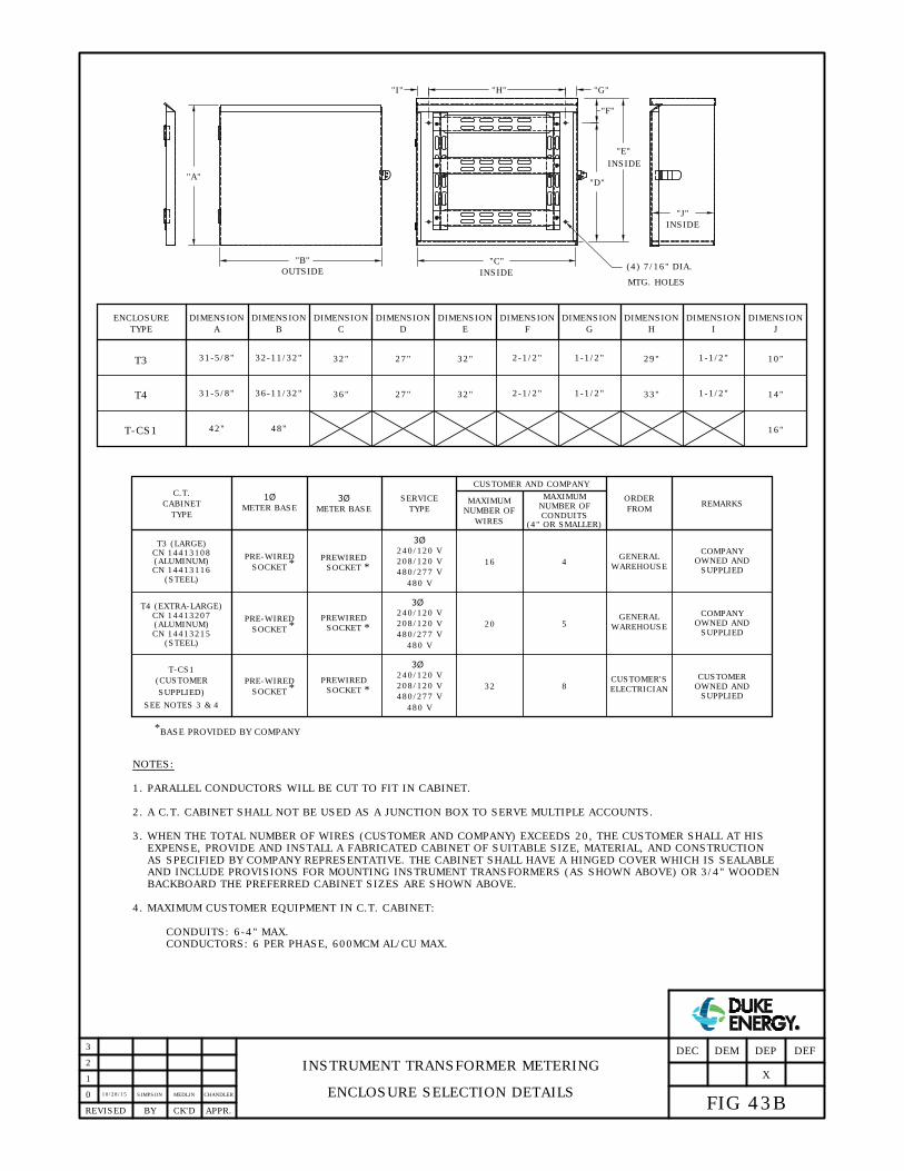
INSTRUMENT TRANSFORMER METERING
ENCLOSURE SELECTION DETAILS
10/28/15
SIMPSON
REVISED BY CK'D APPR.
0
OUTSIDE
(4) 7/16" DIA.
MTG. HOLES
C.T.
CABINET
TYPE
SERVICE
TYPE
3Ø
240/120 V
208/120 V
480/277 V
480 V
3Ø
240/120 V
208/120 V
480/277 V
480 V
NUMBER OF
WIRES
16
20
MAXIMUM
NUMBER OF
CONDUITS
4
5
ORDER
FROM
WAREHOUSE
WAREHOUSE
REMARKS
BASE PROVIDED BY COMPANY
"B"
"A"
"J"
INSIDE
"C"
INSIDE
"D"
"F"
"E"
INSIDE
"I" "G""H"
METER BASE
3Ø
PRE-WIRED
SOCKET
PREWIRED
SOCKET
MAXIMUM
36-11/32"
32-11/32"
DIMENSION
T4
T3
TYPE
ENCLOSURE
31-5/8"
31-5/8"
DIMENSION
A
27"
27"
DIMENSION
32"
36"
DIMENSION
B C D
DIMENSION
32"
32"
E
2-1/2"
2-1/2"
DIMENSION
F
1-1/2"
1-1/2"
DIMENSIONDIMENSION
1-1/2"
1-1/2"
DIMENSION
G
33"
29"
H
DIMENSION
14"
10"
I J
*
NOTES:
3. WHEN THE TOTAL NUMBER OF WIRES (CUSTOMER AND COMPANY) EXCEEDS 20, THE CUSTOMER SHALL AT HIS
EXPENSE, PROVIDE AND INSTALL A FABRICATED CABINET OF SUITABLE SIZE, MATERIAL, AND CONSTRUCTION
AS SPECIFIED BY COMPANY REPRESENTATIVE. THE CABINET SHALL HAVE A HINGED COVER WHICH IS SEALABLE
AND INCLUDE PROVISIONS FOR MOUNTING INSTRUMENT TRANSFORMERS (AS SHOWN ABOVE) OR 3/4" WOODEN
BACKBOARD THE PREFERRED CABINET SIZES ARE SHOWN ABOVE.
1. PARALLEL CONDUCTORS WILL BE CUT TO FIT IN CABINET.
2. A C.T. CABINET SHALL NOT BE USED AS A JUNCTION BOX TO SERVE MULTIPLE ACCOUNTS.
GENERAL
GENERAL
48"
T-CS1
42"
16"
3Ø
240/120 V
208/120 V
480/277 V
480 V
32 8
ELECTRICIAN
T-CS1
(CUSTOMER
SUPPLIED)
CUSTOMER'S
COMPANY
COMPANY
OWNED AND
CUSTOMER
*
*
PREWIRED
SOCKET*
PREWIRED
SOCKET *
METER BASE
1Ø
CUSTOMER AND COMPANY
SEE NOTES 3 & 4
(4" OR SMALLER)
SUPPLIED
OWNED AND
SUPPLIED
OWNED AND
SUPPLIED
T3 (LARGE)
CN 14413108
CN 14413116
(ALUMINUM)
(STEEL)
T4 (EXTRA-LARGE)
CN 14413207
(ALUMINUM)
CN 14413215
(STEEL)
4. MAXIMUM CUSTOMER EQUIPMENT IN C.T. CABINET:
CONDUITS: 6-4" MAX.
CONDUCTORS: 6 PER PHASE, 600MCM AL/CU MAX.
1
PRE-WIRED
SOCKET
*
PRE-WIRED
SOCKET
*
2
3
FIG 43B
DEFDEPDEMDEC
X
CHANDLERMEDLIN
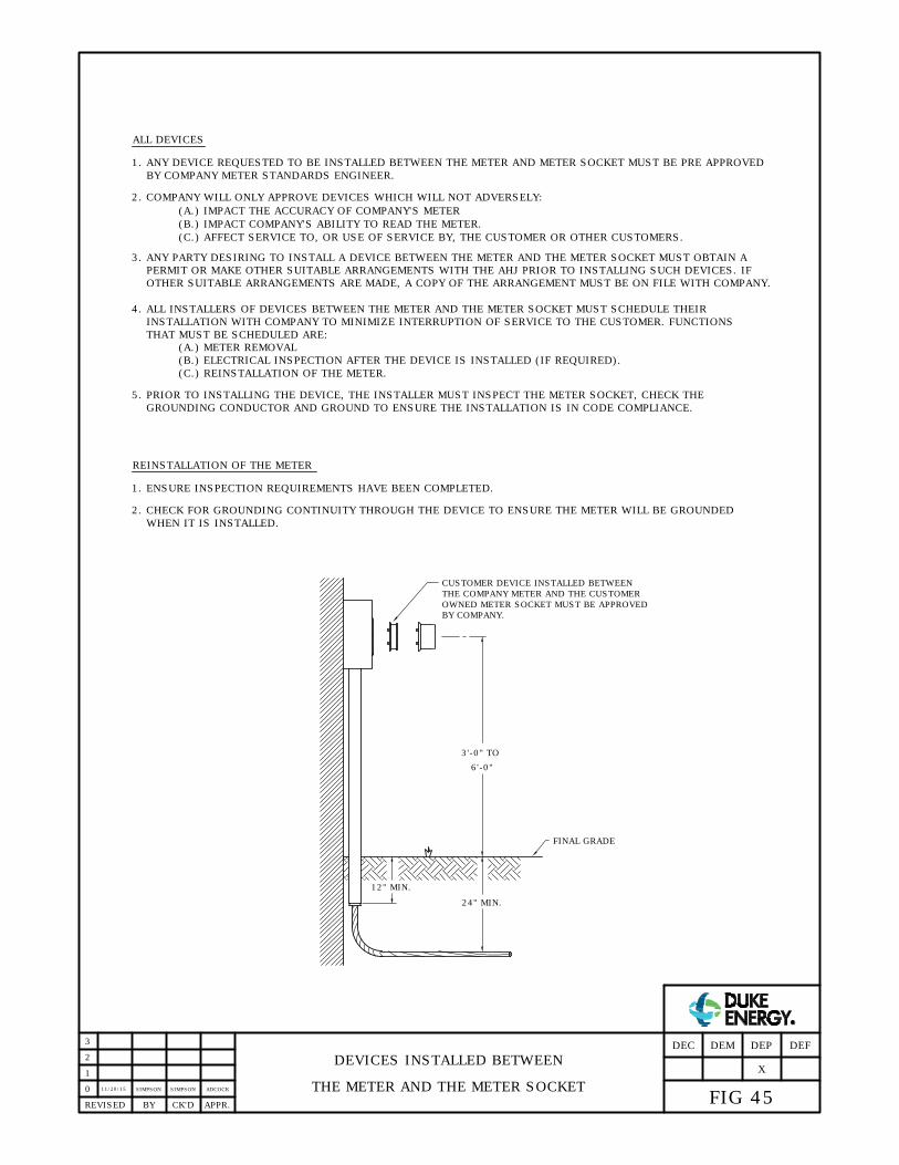
ALL DEVICES
1. ANY DEVICE REQUESTED TO BE INSTALLED BETWEEN THE METER AND METER SOCKET MUST BE PRE APPROVED
BY COMPANY METER STANDARDS ENGINEER.
2. COMPANY WILL ONLY APPROVE DEVICES WHICH WILL NOT ADVERSELY:
(A.) IMPACT THE ACCURACY OF COMPANY'S METER
(B.) IMPACT COMPANY'S ABILITY TO READ THE METER.
(C.) AFFECT SERVICE TO, OR USE OF SERVICE BY, THE CUSTOMER OR OTHER CUSTOMERS.
3. ANY PARTY DESIRING TO INSTALL A DEVICE BETWEEN THE METER AND THE METER SOCKET MUST OBTAIN A
PERMIT OR MAKE OTHER SUITABLE ARRANGEMENTS WITH THE AHJ PRIOR TO INSTALLING SUCH DEVICES. IF
OTHER SUITABLE ARRANGEMENTS ARE MADE, A COPY OF THE ARRANGEMENT MUST BE ON FILE WITH COMPANY.
4. ALL INSTALLERS OF DEVICES BETWEEN THE METER AND THE METER SOCKET MUST SCHEDULE THEIR
INSTALLATION WITH COMPANY TO MINIMIZE INTERRUPTION OF SERVICE TO THE CUSTOMER. FUNCTIONS
THAT MUST BE SCHEDULED ARE:
(A.) METER REMOVAL
(B.) ELECTRICAL INSPECTION AFTER THE DEVICE IS INSTALLED (IF REQUIRED).
(C.) REINSTALLATION OF THE METER.
5. PRIOR TO INSTALLING THE DEVICE, THE INSTALLER MUST INSPECT THE METER SOCKET, CHECK THE
GROUNDING CONDUCTOR AND GROUND TO ENSURE THE INSTALLATION IS IN CODE COMPLIANCE.
1. ENSURE INSPECTION REQUIREMENTS HAVE BEEN COMPLETED.
REINSTALLATION OF THE METER
2. CHECK FOR GROUNDING CONTINUITY THROUGH THE DEVICE TO ENSURE THE METER WILL BE GROUNDED
WHEN IT IS INSTALLED.
12" MIN.
FINAL GRADE
3'-0" TO
6'-0"
CUSTOMER DEVICE INSTALLED BETWEEN
THE COMPANY METER AND THE CUSTOMER
OWNED METER SOCKET MUST BE APPROVED
BY COMPANY.
24" MIN.
DEVICES INSTALLED BETWEEN
THE METER AND THE METER SOCKET0
3
2
1
APPR.REVISED BY CK'D
11/20/15
ADCOCKSIMPSON SIMPSON
FIG 45
DEFDEP
X
DEMDEC
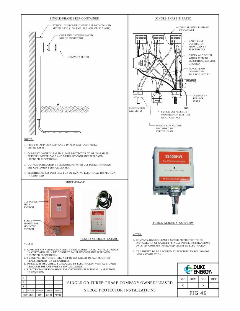
11/30/10SIMPSON SIMPSON ELKINS
0
3
2
1
APPR.REVISED BY CK'D
NOTES:
SINGLE OR THREE-PHASE COMPANY OWNED/LEASED
SURGE PROTECTOR INSTALLATIONS
IN CUSTOMER MAIN DISCONNECT PANEL BY COMPANY-APPROVED
3. OUTAGE, IF REQUIRED, SCHEDULED BY ELECTRICIAN WITH CUSTOMER
4. ELECTRICIAN RESPONSIBLE FOR OBTAINING ELECTRICAL INSPECTION,
1. COMPANY-OWNED/LEASED SURGE PROTECTORS TO BE INSTALLED ONLY
2. SURGE PROTECTORS SHALL NOT BE INSTALLED IN PAD-MOUNTED
TYPICAL CUSTOMER-OWNED SELF-CONTAINED
METER BASE (100 AMP, 200 AMP OR 320 AMP)
COMPANY-OWNED/LEASED
SURGE PROTECTOR
COMPANY METER
NOTES:
1. FITS 100 AMP, 200 AMP AND 320 AMP SELF-CONTAINED
2. COMPANY-OWNED/LEASED SURGE PROTECTOR TO BE INSTALLED
BETWEEN METER BASE AND METER BY COMPANY-APPROVED
3. OUTAGE SCHEDULED BY ELECTRICIAN WITH CUSTOMER THROUGH
4. ELECTRICIAN RESPONSIBLE FOR OBTAINING ELECTRICAL INSPECTION,
NOTES:
1. COMPANY-OWNED/LEASED SURGE PROTECTOR TO BE
2. CT CABINET TO BE SECURED BY ELECTRICIAN FOLLOWING
INSTALLED IN CT CABINET (SINGLE-PHASE INSTALLATIONS
PEMCO MODEL # SS400HW
ONLY) BY COMPANY-APPROVED LICENSED ELECTRICIAN.
WORK COMPLETION.
METER BASES.
LICENSED ELECTRICIAN.
THE CUSTOMER SERVICE CENTER.
IF REQUIRED.
PEMCO MODEL # EXT50C
CUSTOMER
MAIN
PROTECTOR
MOUNTED
400
ASTRA
X
1
X
2
H
1
2
H
COMPANY'S
SERVICE
RISER
TYPICAL SINGLE-PHASE
CT CABINET
PIERCE CONNECTOR
PROVIDED BY
BLACK LEADS
CONNECTED
CUSTOMER'S
FACILITIES
MOUNTED ON BOTTOM
OF CT CABINET
SURGE SUPPRESSOR
GREEN AND WHITE
WIRES TIED TO
ELECTRICIAN
ELECTRICAL SERVICE
SPLIT-BOLT
CONNECTOR
SWITCH
SWITCH
SURGE
PROVIDED BY
ELECTRICIAN
GROUND
TO EACH HOTLEG
LICENSED ELECTRICIAN.
TRANSFORMERS OR CT CABINETS.
THROUGH THE CUSTOMER SERVICE CENTER.
IF REQUIRED.
THREE-PHASE
SINGLE-PHASE SELF-CONTAINED SINGLE-PHASE T-RATED
FIG 46
DEFDEP
X
DEMDEC
X
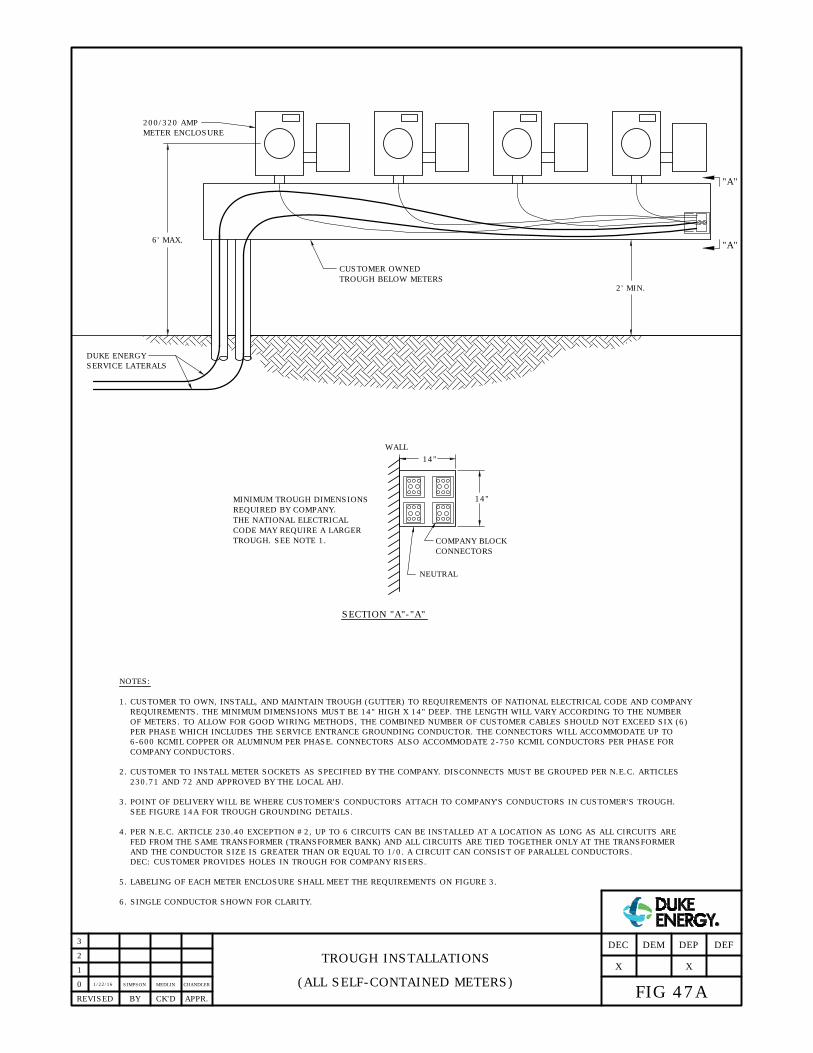
NOTES:
1. CUSTOMER TO OWN, INSTALL, AND MAINTAIN TROUGH (GUTTER) TO REQUIREMENTS OF NATIONAL ELECTRICAL CODE AND COMPANY
FED FROM THE SAME TRANSFORMER (TRANSFORMER BANK) AND ALL CIRCUITS ARE TIED TOGETHER ONLY AT THE TRANSFORMER
3. POINT OF DELIVERY WILL BE WHERE CUSTOMER'S CONDUCTORS ATTACH TO COMPANY'S CONDUCTORS IN CUSTOMER'S TROUGH.
PER PHASE WHICH INCLUDES THE SERVICE ENTRANCE GROUNDING CONDUCTOR. THE CONNECTORS WILL ACCOMMODATE UP TO
OF METERS. TO ALLOW FOR GOOD WIRING METHODS, THE COMBINED NUMBER OF CUSTOMER CABLES SHOULD NOT EXCEED SIX (6)
REQUIREMENTS. THE MINIMUM DIMENSIONS MUST BE 14" HIGH X 14" DEEP. THE LENGTH WILL VARY ACCORDING TO THE NUMBER
DEC: CUSTOMER PROVIDES HOLES IN TROUGH FOR COMPANY RISERS.
AND THE CONDUCTOR SIZE IS GREATER THAN OR EQUAL TO 1/0. A CIRCUIT CAN CONSIST OF PARALLEL CONDUCTORS.
4. PER N.E.C. ARTICLE 230.40 EXCEPTION #2, UP TO 6 CIRCUITS CAN BE INSTALLED AT A LOCATION AS LONG AS ALL CIRCUITS ARE
2. CUSTOMER TO INSTALL METER SOCKETS AS SPECIFIED BY THE COMPANY. DISCONNECTS MUST BE GROUPED PER N.E.C. ARTICLES
SEE FIGURE 14A FOR TROUGH GROUNDING DETAILS.
1/22/16
SIMPSON MEDLIN CHANDLER
TROUGH INSTALLATIONS
(ALL SELF-CONTAINED METERS)0
APPR.REVISED BY CK'D
5. LABELING OF EACH METER ENCLOSURE SHALL MEET THE REQUIREMENTS ON FIGURE 3.
6-600 KCMIL COPPER OR ALUMINUM PER PHASE. CONNECTORS ALSO ACCOMMODATE 2-750 KCMIL CONDUCTORS PER PHASE FOR
1
2
3
FIG 47A
DEFDEP
X
DEMDEC
CUSTOMER OWNED
TROUGH BELOW METERS
200/320 AMP
METER ENCLOSURE
DUKE ENERGY
SERVICE LATERALS
2' MIN.
6' MAX.
14"
14"
WALL
NEUTRAL
MINIMUM TROUGH DIMENSIONS
REQUIRED BY COMPANY.
THE NATIONAL ELECTRICAL
CODE MAY REQUIRE A LARGER
TROUGH. SEE NOTE 1.
COMPANY BLOCK
CONNECTORS
SECTION "A"-"A"
COMPANY CONDUCTORS.
X
6. SINGLE CONDUCTOR SHOWN FOR CLARITY.
"A"
"A"
230.71 AND 72 AND APPROVED BY THE LOCAL AHJ.

1/22/16
SIMPSON
TROUGH INSTALLATIONS
CT CABINETS0
APPR.REVISED BY CK'D
1
2
3
FIG 47B
DEFDEP
X
DEMDEC
CUSTOMER OWNED
TROUGH BELOW METERS
200/320 AMP
METER ENCLOSURE
2' MIN.
6' MAX.
X
NOTES:
1. MINIMUM TROUGH DIMENSIONS REQUIRED BY COMPANY. THE NATIONAL ELECTRICAL CODE MAY REQUIRE
2. SEE FIGURES 14A AND 14B FOR GROUNDING DETAILS.
3. SINGLE CONDUCTOR SHOWN FOR CLARITY.
CT CABINET
14"
14"
WALL
NEUTRAL
"A"
COMPANY BLOCK
CONNECTORS
SECTION "A"-"A"
"A"
4. FOR DEC: CUSTOMER CUTS HOLES IN TROUGH FOR COMPANY RISERS.
DUKE ENERGY
SERVICE
3' - 6'
LATERALS
SEPARATE
SERVICE
LATERAL TO
CT CABINET
SEE NOTE 1
A LARGER TROUGH. SEE FIGURE 47A FOR TROUGH SPECIFICATIONS AND CONDUCTOR CONNECTION DETAILS.
MEDLIN CHANDLER
30"
5. REFER TO FIGURES 43A AND 43B FOR CT CABINET DETAILS.
ALL CIRCUITS ARE FED FROM THE SAME TRANSFORMER (TRANSFORMER BANK) AND ALL CIRCUITS ARE TIED
TOGETHER ONLY AT THE TRANSFORMER AND THE CONDUCTOR SIZE IS GREATER THAN OR EQUAL TO 1/0. A
CIRCUIT CAN CONSIST OF PARALLEL CONDUCTORS. DEC: CUSTOMER PROVIDES HOLES IN TROUGH FOR
COMPANY RISERS.
6. PER N.E.C. ARTICLE 230.40 EXCEPTION #2, UP TO 6 CIRCUITS CAN BE INSTALLED AT A LOCATION AS LONG AS
PER N.E.C. ARTICLES 230.71 AND 72 AND APPROVED BY THE LOCAL AHJ.
7. CUSTOMER TO INSTALL METER SOCKETS AS SPECIFIED BY THE COMPANY. DISCONNECTS MUST BE GROUPED
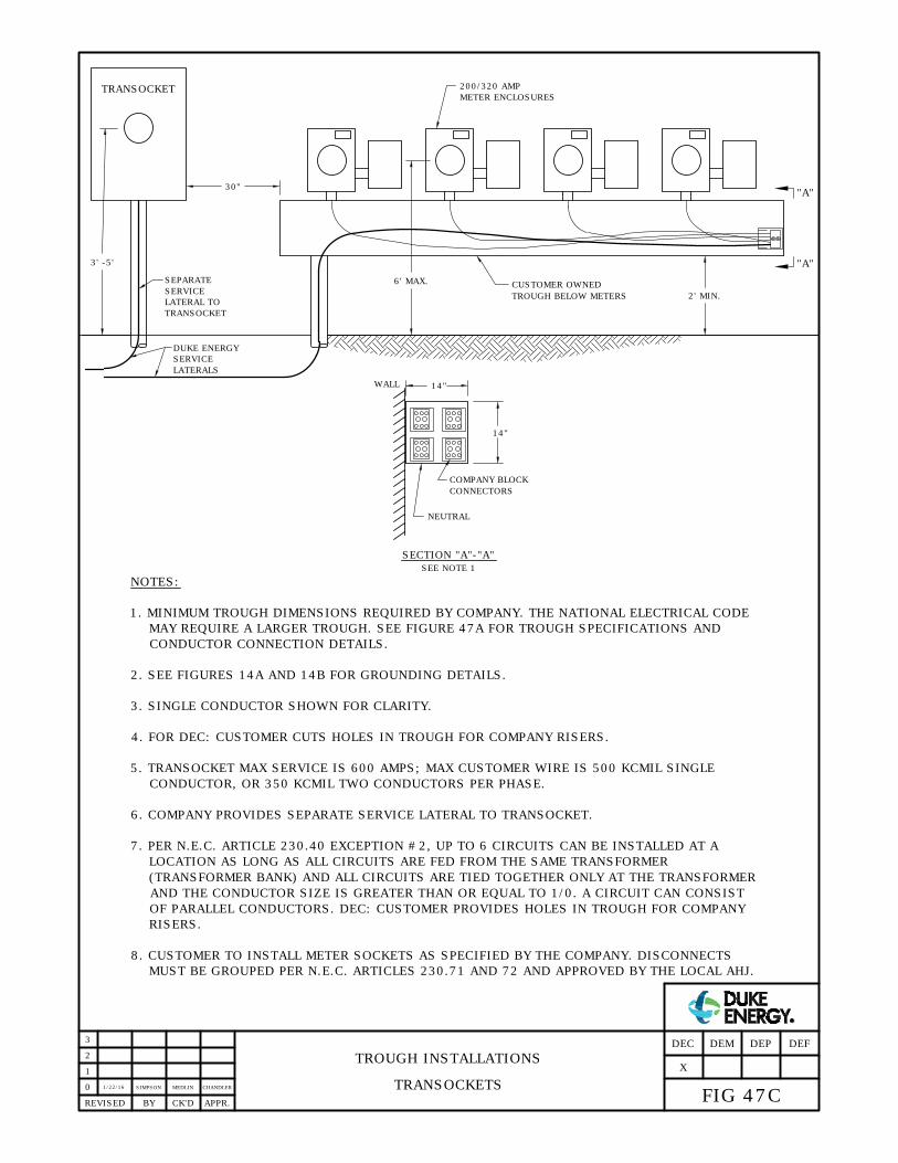
1/22/16
SIMPSON
TROUGH INSTALLATIONS
TRANSOCKETS0
APPR.REVISED BY CK'D
1
2
3
FIG 47C
DEFDEPDEMDEC
CUSTOMER OWNED
TROUGH BELOW METERS 2' MIN.
6' MAX.
X
TRANSOCKET
14"
14"
WALL
NEUTRAL
"A"
COMPANY BLOCK
CONNECTORS
SECTION "A"-"A"
"A"
DUKE ENERGY
SERVICE
LATERALS
SEPARATE
SERVICE
LATERAL TO
TRANSOCKET
SEE NOTE 1
MEDLIN CHANDLER
NOTES:
1. MINIMUM TROUGH DIMENSIONS REQUIRED BY COMPANY. THE NATIONAL ELECTRICAL CODE
MAY REQUIRE A LARGER TROUGH. SEE FIGURE 47A FOR TROUGH SPECIFICATIONS AND
CONDUCTOR CONNECTION DETAILS.
2. SEE FIGURES 14A AND 14B FOR GROUNDING DETAILS.
3. SINGLE CONDUCTOR SHOWN FOR CLARITY.
4. FOR DEC: CUSTOMER CUTS HOLES IN TROUGH FOR COMPANY RISERS.
5. TRANSOCKET MAX SERVICE IS 600 AMPS; MAX CUSTOMER WIRE IS 500 KCMIL SINGLE
CONDUCTOR, OR 350 KCMIL TWO CONDUCTORS PER PHASE.
6. COMPANY PROVIDES SEPARATE SERVICE LATERAL TO TRANSOCKET.
7. PER N.E.C. ARTICLE 230.40 EXCEPTION #2, UP TO 6 CIRCUITS CAN BE INSTALLED AT A
LOCATION AS LONG AS ALL CIRCUITS ARE FED FROM THE SAME TRANSFORMER
(TRANSFORMER BANK) AND ALL CIRCUITS ARE TIED TOGETHER ONLY AT THE TRANSFORMER
AND THE CONDUCTOR SIZE IS GREATER THAN OR EQUAL TO 1/0. A CIRCUIT CAN CONSIST
OF PARALLEL CONDUCTORS. DEC: CUSTOMER PROVIDES HOLES IN TROUGH FOR COMPANY
RISERS.
8. CUSTOMER TO INSTALL METER SOCKETS AS SPECIFIED BY THE COMPANY. DISCONNECTS
MUST BE GROUPED PER N.E.C. ARTICLES 230.71 AND 72 AND APPROVED BY THE LOCAL AHJ.
30"
200/320 AMP
METER ENCLOSURES
3' -5'

1/22/16
SIMPSON
TROUGH INSTALLATIONS
TROUGH LOCATED ABOVE COMPANY'S METERS0
APPR.REVISED BY CK'D
1
2
3
FIG 47D
DEFDEPDEMDEC
X
DUKE ENERGY SERVICE LATERALS
SIZED FOR LOAD
MEDLIN CHANDLER
NOTES:
1. EMPTY CABINET PROVIDED AND INSTALLED BY CUSTOMER IN CASES WHERE CUSTOMER DESIRES TROUGH
LOCATION ABOVE COMPANY'S METERS.
2. CUSTOMER CUTS HOLE IN CABINET AND TROUGH. CONDUITS ENTERING CABINET MUST BE TOGETHER, NOT
3. SEE FIGURE 14A FOR TROUGH GROUNDING DETAILS. COMPANY GROUNDS CABINET.
4. FOR INSTALLATIONS WITHIN DEC, REFER TO FIG 43A FOR CUSTOMER WIRE SIZE GUIDELINES AND CABINET
5. FOR INSTALLATIONS WITHIN DEP, REFER TO FIG 43B FOR CUSTOMER WIRE SIZE GUIDELINES AND CABINET
CUSTOMER PROVIDED TROUGH
D
M
D
M
D
M
D
M
3'-6'
EMPTY CABINET PROVIDED
AND INSTALLED BY
CUSTOMER. SEE NOTES 4
P.O.D.
CUSTOMER WIRING
AND 5 FOR PROPER SIZING
PER N.E.C. ARTICLES 230.71 AND 72 AND APPROVED BY THE LOCAL AHJ.
6. CUSTOMER TO INSTALL METER SOCKETS AS SPECIFIED BY THE COMPANY. DISCONNECTS MUST BE GROUPED
X
CONNECTIONS PROVIDED
AND INSTALLED BY
COMPANY
IN SEPARATE CORNERS OR SIDES.
SIZING.
SIZING.
6/29/16
ADCOCKEANES FLETCHER
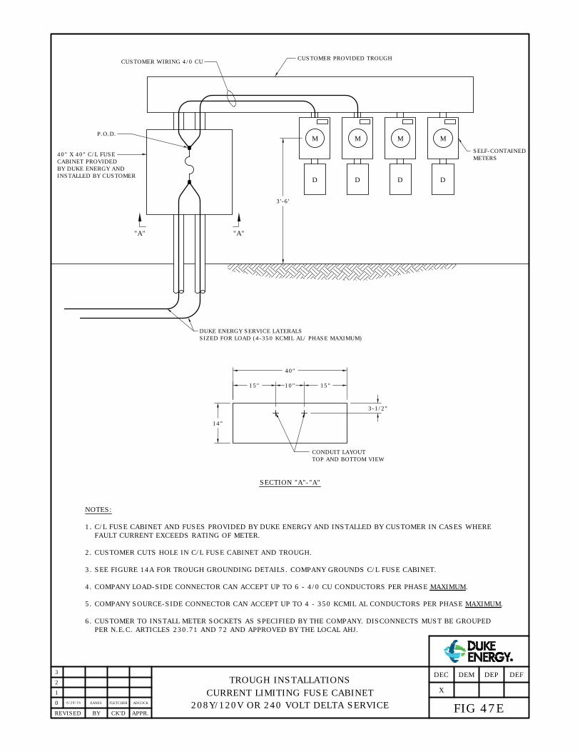
TROUGH INSTALLATIONS
CURRENT LIMITING FUSE CABINET
208Y/120V OR 240 VOLT DELTA SERVICE
0
APPR.REVISED BY CK'D
1
2
3
FIG 47E
DEFDEPDEMDEC
X
DUKE ENERGY SERVICE LATERALS
SIZED FOR LOAD (4-350 KCMIL AL/ PHASE MAXIMUM)
NOTES:
1. C/L FUSE CABINET AND FUSES PROVIDED BY DUKE ENERGY AND INSTALLED BY CUSTOMER IN CASES WHERE
FAULT CURRENT EXCEEDS RATING OF METER.
2. CUSTOMER CUTS HOLE IN C/L FUSE CABINET AND TROUGH.
3. SEE FIGURE 14A FOR TROUGH GROUNDING DETAILS. COMPANY GROUNDS C/L FUSE CABINET.
4. COMPANY LOAD-SIDE CONNECTOR CAN ACCEPT UP TO 6 - 4/0 CU CONDUCTORS PER PHASE MAXIMUM.
5. COMPANY SOURCE-SIDE CONNECTOR CAN ACCEPT UP TO 4 - 350 KCMIL AL CONDUCTORS PER PHASE MAXIMUM.
CUSTOMER PROVIDED TROUGH
"A""A"
D
M
D
M
D
M
D
M
3'-6'
40" X 40" C/L FUSE
CABINET PROVIDED
BY DUKE ENERGY AND
P.O.D.
CUSTOMER WIRING 4/0 CU
SELF-CONTAINED
METERS
40"
15" 15"10"
3-1/2"
14"
CONDUIT LAYOUT
TOP AND BOTTOM VIEW
SECTION "A"-"A"
INSTALLED BY CUSTOMER
PER N.E.C. ARTICLES 230.71 AND 72 AND APPROVED BY THE LOCAL AHJ.
6. CUSTOMER TO INSTALL METER SOCKETS AS SPECIFIED BY THE COMPANY. DISCONNECTS MUST BE GROUPED
6/29/16
ADCOCKEANES FLETCHER
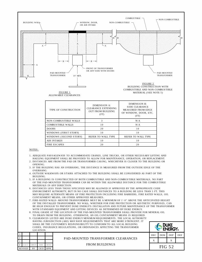
PAD-MOUNTED TRANSFORMER CLEARANCES
FROM BUILDINGS0
APPR.REVISED BY CK'D
1
FIG 52
DEFDEP
X
DEMDEC
2
X
NOTES:
1. ADEQUATE PASSAGEWAYS TO ACCOMMODATE CRANES, LINE TRUCKS, OR OTHER NECESSARY LIFTING AND
HAULING EQUIPMENT SHALL BE PROVIDED TO ALLOW FOR MAINTENANCE, OPERATION, OR REPLACEMENT.
2. DISTANCES ARE FROM THE PAD OR TRANSFORMER CASING, WHICHEVER IS CLOSER TO THE BUILDING OR
OPENING.
3. IF THE BUILDING HAS AN OVERHANG, THE DISTANCE IS MEASURED FROM THE OUTSIDE EDGE OF THE
OVERHANG.
4. OUTSIDE WALKWAYS OR STAIRS ATTACHED TO THE BUILDING SHALL BE CONSIDERED AS PART OF THE
BUILDING.
5. IF A BUILDING IS CONSTRUCTED OF BOTH COMBUSTIBLE AND NON-COMBUSTIBLE MATERIALS, NO PART
OF THE PAD-MOUNTED TRANSFORMER CAN BE WITHIN THE ALLOWABLE DISTANCE FOR THE COMBUSTIBLE
MATERIALS IN ANY DIRECTION.
6. DISTANCES LESS THAN THOSE SPECIFIED MAY BE ALLOWED IF APPROVED BY THE APPROPRIATE CODE
ENFORCEMENT AUTHORITY, BUT IN NO CASE SHALL DISTANCES TO A BUILDING BE LESS THAN 3 FT. THIS
CONTAINMENT MEANS, OR OTHER APPROVED MEASURES.
8. FINAL GRADE AT THE LOCATION OF THE PAD-MOUNTED TRANSFORMER SHALL PROVIDE FOR MINERAL OIL
TO DRAIN FROM THE BUILDING. OTHERWISE, AN OIL CONTAINMENT MEANS IS REQUIRED.
SHALL BE THE CUSTOMER'S RESPONSIBILITY TO CONFORM TO ALL LOCAL BUILDING
CODES, INSURANCE REGULATIONS, OR ORDINANCES AFFECTING THE TRANSFORMER
TYPE OF CONSTRUCTION
NON-COMBUSTIBLE WALLS
COMBUSTIBLE WALLS
DOORS
WINDOWS (SECOND STORY)
AIR INTAKES
FIRE ESCAPES
CLEARANCE EXTENDING
DIMENSION A:
OUT FROM BUILDING
SIDE CLEARANCE
DIMENSION B:
3
10
20
REFER TO WALL TYPE
20
10
REFER TO WALL TYPE
20
(FT)
B B
10' MIN.
PAD-MOUNTED
TRANSFORMER
A
A A
WINDOW, DOOR,
OR AIR INTAKE
BUILDING WALL
FRONT OF TRANSFORMER
OR ANY SIDE WITH DOORS
A
FIGURE 1
ALLOWABLE CLEARANCES
FIGURE 2
BUILDING CONSTRUCTION WITH
COMBUSTIBLE AND NON-COMBUSTIBLE
MATERIAL (SEE NOTE 5)
NON-COMBUSTIBLE
NON-COMBUSTIBLE
COMBUSTIBLE
10 10
MEASURED FROM EDGE
N/A
N/A
PAD-MOUNTED
TRANSFORMER
MAY REQUIRE ALTERNATE MEANS OF FIRE PROTECTION INCLUDING FIRE BARRIERS, FIRE RATED WALLS, OIL
9. CLEARANCES LISTED ARE DUKE ENERGY MINIMUM REQUIREMENTS. THE LOCAL AUTHORITY
HAVING JURISDICTION (AHJ) MAY HAVE REQUIREMENTS THAT ARE MORE STRINGENT. IT
WINDOWS (FIRST STORY) 10 10
OF WINDOW, DOOR, ETC.
(FT)
7. FIRE-RATED WALLS AROUND TRANSFORMERS MUST BE A MINIMUM OF 1'-0" ABOVE THE ANTICIPATED HEIGHT
OF THE INSTALLED TRANSFORMER. NO WALL, WHETHER FOR FIRE PROTECTION OR AESTHETIC PURPOSES, CAN
BE HIGH ENOUGH TO PREVENT DUKE ENERGY'S INSTALLATON AND FUTURE MAINTENANCE OF THE TRANSFORMER
WITH STANDARD EQUIPMENT AND LIFTING DEVICES AS DETERMINED BY DUKE ENERGY.
LOCATION.
10/28/15EANESSIMPSON ADCOCK
3

PAD-MOUNTED EQUIPMENT WORKING SPACE
AND MISCELLANEOUS CLEARANCES0
APPR.REVISED BY CK'D
1
2
3
FIG 53
DEFDEP
X
DEMDEC
1/18/16
EANES
X
NOTES:
1. ADEQUATE PASSAGEWAYS TO ACCOMMODATE CRANES, LINE TRUCKS, OR OTHER NECESSARY LIFTING AND
HAULING EQUIPMENT SHALL BE PROVIDED TO ALLOW FOR MAINTENANCE, OPERATION, OR REPLACEMENT.
2. DISTANCES ARE FROM THE PAD OR SURFACE MOUNTED EQUIPMENT, WHICHEVER IS CLOSER TO THE OBJECT
IN QUESTION.
3. A MINIMUM CLEAR WORKING SPACE OF 5 FT MUST BE MAINTAINED FROM EACH NON-DOOR SIDE OF THE
EQUIPMENT (TO ACCOMMODATE CONTROL CABINETS, ETC.).
4. WHERE A METER IS MOUNTED TO A TRANSFORMER, A CLEAR SPACE AROUND THE METER OF AT LEAST 3 FT
WIDE, 4 FT DEEP, AND 8 FT HIGH MUST BE PROVIDED AND ALWAYS AVAILABLE FOR READING, INSPECTING,
TESTING, AND MAINTENANCE OPERATIONS.
5. DISTANCES LESS THAN THOSE SPECIFIED MAY BE ALLOWED IF APPROVED BY THE APPROPRIATE CODE
ENFORCEMENT AUTHORITY. THIS MAY REQUIRE ALTERNATE MEANS OF FIRE PROTECTION INCLUDING FIRE
BARRIERS, FIRE RATED WALLS, SPRINKLER SYSTEMS, OIL CONTAINMENT MEANS, OR OTHER APPROVED
MEASURES.
6. IT SHALL BE THE CUSTOMER'S RESPONSIBILITY TO CONFORM TO ALL LOCAL BUILDING CODES, INSURANCE
REGULATIONS, OR ORDINANCES AFFECTING THE EQUIPMENT LOCATION.
TYPE OF EQUIPMENT IN ANY DIRECTION
FUEL OR GAS DISPENSERS
CONTAINERS STORING FLAMMABLE LIQUID OR GAS
CUSTOMER-OWNED GENERATORS OR TRANSFORMERS
FIRE HYDRANTS
NATURAL GAS METERS
MISCELLANEOUS CLEARANCES
20
10
10
(SEE NOTE 7)
3
(FT)
CLEARANCE
B
A
PAD-MOUNTED
EQUIPMENT
A
B
TYPE OF PAD-MOUNTED EQUIPMENT
TRANSFORMERS (SEE NOTE 4)
SWITCHGEAR (SEE NOTE 3)
RECLOSERS, PRIMARY METERS, ETC.
DOOR SIDES
(FT)
DIMENSION A
(FT)
DIMENSION B
10
10
10
3
5
3
MINIMUM CLEAR WORKING SPACE AROUND PAD-MOUNTED EQUIPMENT
7. 4 FT, MAY BE REDUCED TO 3 FT BY AGREEMENT WITH LOCAL FIRE AUTHORITY.
EANES ADCOCK

MAXIMUM NUMBER OF CUSTOMER
CONDUCTORS IN SECONDARY COMPARTMENT
OF THREE-PHASE PAD-MOUNTED TRANSFORMERS
0
APPR.REVISED BY CK'D
1
NOTES:
1. IF THE RECOMMENDED CONDUCTOR LIMITS ABOVE ARE EXCEEDED, A SECONDARY BUSS ENCLOSURE WILL BE
REQUIRED. CONTACT COMPANY REPRESENTATIVE FOR DETAILS.
2. MAXIMUM CUSTOMER CONDUCTOR SIZE IS 750 KCMIL CU/AL.
3. PARALLELED CUSTOMER CONDUCTORS MUST BE "RUNG OUT" (OHMED OUT) PRIOR TO ENERGIZING TO
PREVENT CROSS PHASING.
4. ALL NEW THREE-PHASE PAD-MOUNTED TRANSFORMERS WITH A 4160Y/2400 VOLT SECONDARY HAVE
SECONDARY LIVE-FRONT BUSHINGS WITH A 4-HOLE SPADE (0.56" DIAMETER BOLT HOLES ON 1.75" CENTERS).
2
FIG 58
DEFDEP
X
DEMDEC
X
3
2/1/16
SIMPSON EANES ADCOCK
PER PHASE IN PAD-MOUNTED TRANSFORMERS
MAXIMUM NUMBER OF CUSTOMER CONDUCTORS
TRANSFORMER SIZE
PAD-MOUNTED
(KVA)
300
500
1000
750
1500
2500
150
75
3750
16
16
12
12
12
12
12
12
16
480Y/277
N/A
N/A
16
16
12
12
12
12
N/A
208Y/120
CONDUCTOR SIZES
DEC ONLY
10
10
10
10
10
10
10
10
N/A
350MCM TO 600MCM
8
8
8
8
8
8
8
8
N/A
CONDUCTOR SIZES
700MCM TO 750MCM
DEP ONLY
2000 *
DEC ONLY
IN PAD-MOUNTED TRANSFORMERS
MAXIMUM NUMBER OF CONDUCTORS PER PHASE
225 10 8
10 8
*
N/AN/A
N/A N/A
*
DEP ONLY**
**
5. 208Y/120V SECONDARY VOLTAGE NOT AVAILABLE IN EITHER AREA FOR SIZES GREATER THAN 1000 KVA.
6/29/16ADCOCKEANES FLETCHER

FAULT CURRENT TO FLOW.
FROM THEIR PANEL TO THE TRANSFORMER. THIS NEUTRAL CONDUCTOR PROVIDES A PATH FOR GROUND
1. IF THE TRANSFORMER SECONDARY NEUTRAL IS GROUNDED, THE CUSTOMER MUST CONNECT A CONDUCTOR
NOTES:
2. A TRANSFORMER CONNECTED FOR FOUR WIRE SERVICE (GROUNDED NEUTRAL) CANNOT SUPPLY THREE
AØ
BØ
CØ
NEUTRAL
NEUTRAL NEUTRAL
STRAP TO
TANKS
CONNECTION
TO PAD
NEUTRAL
STRAP TO TANK
& CONNECTION TO
PAD NEUTRAL
NEUTRAL
PHASE WIRES
TRANSFORMER CUSTOMER'S PANEL
IF TRANSFORMER SYSTEM IS
GROUNDED, CONDUCTOR IS
REQUIRED BY N.E.C. ARTICLE
250.24(C) TO PROVIDE FAULT
CURRENT PATH.
BONDING WIRES (BARE OR GREEN)
SHOULD NOT BE RUN
BY THE CUSTOMER
GROUND FAULT
CURRENT FLOW
BARE STEEL
IS BONDED
CONDUIT
WIRE SERVICES.
Ho Xo
FOUR WIRE SERVICES,
GROUNDED WYE CONNECTION0
2
1
APPR.REVISED BY CK'D
COMPANY WILL NOT
CONNECT, SEE
3. A SEPARATE BONDING CONDUCTOR OR CONDUCTORS ARE NOT NECESSARY. ELECTRICIANS SHOULD
BE ADVISED NOT TO RUN BONDING CONDUCTORS. IF THEY INSIST ON RUNNING BONDING
CONDUCTORS, DUKE ENERGY WILL NOT CONNECT THEM TO ANY COMPANY EQUIPMENT.
NOTE 3
BUILDING STEEL
CUSTOMER GROUNDING BUSS
CONNECTOR IN CUSTOMER'S
PANEL (NOT IN CT CABINET)
METAL
WATER
PIPE IS
IS BONDED
BONDED
GROUNDING BUSS TIED TO
NEUTRAL IN CUSTOMER
SWITCHGEAR
4. NOTE FOR DELIVERY VOLTAGES OF 4160Y/2400 VOLTS THREE-PHASE 4-WIRE AND 2400 VOLT THREE-PHASE
3-WIRE DELTA: N.E.C. REQUIRES CUSTOMER CABLES TO BE TERMINATED WITH VOLTAGE STRESS RELIEF
TERMINATOR (CABLES RATED 25 KV AND HIGHER, N.E.C. ARTICLE 310.10(E)).
3
11/2/15
SIMPSON SIMPSON ADCOCK
FIG 59
DEFDEP
X
DEMDEC
X

THE SECONDARY BUSHING GROUND STRAP. THE SECONDARY NEUTRAL BUSHING MUST BE UNGROUNDED
FLOATING WYE. THE SECONDARY NEUTRAL BUSHING MUST BE CLEAR OF ALL CONNECTIONS, INCLUDING
2. IF THE TRANSFORMER IS CONNECTED FOR THREE WIRE SERVICE, THE SECONDARY IS CONNECTED
NOTES:
AØ
BØ
CØ
NEUTRAL
STRAP TO
TANKS
CONNECTION
TO PAD
NEUTRAL
PHASE WIRES
TRANSFORMER CUSTOMER'S PANEL
TRANSFORMER MUST NOT HAVE
ANY WIRES CONNECTED TO
SECONDARY NEUTRAL BUSHING
A SINGLE BONDING WIRE (BARE OR GREEN)
FAULT CURRENT
FLOW
BARE STEEL
IS BONDED
CONDUIT
SERVICES.
4. DUKE ENERGY SHALL RUN A BONDING CONDUCTOR (#4 BC) FROM THE GROUND LOOP TO THE METERING
HO XO
THREE WIRE SERVICES,
FLOATING WYE CONNECTION0
1
APPR.REVISED BY CK'D
5. CUSTOMER SHOULD BE AWARE THAT A THREE WIRE SERVICE SHOULD ONLY BE USED IN SPECIAL CASES.
LOCATION TO BOND THE METER BOX MOUNTED ON THE WALL OF THE TRANSFORMER TANK. IF THE METER
BOX IS MOUNTED TO THE CUSTOMER'S WALL, THE BONDING CONDUCTOR SHALL BE ATTACHED TO THE
CUSTOMER'S GROUND.
CUSTOMER MUST HAVE A GROUND DETECTION SYSTEM INSTALLED N.E.C. ARTICLE 250.21(B). CUSTOMER
HAVING ELECTRONIC LOADS SUCH AS VARIABLE SPEED DRIVES OR LIGHTNING CONCERNS SHOULD
CONSIDER A GROUNDED WYE CONNECTION.
COMPANY WILL NOT RUN THE BONDING JUMPER
SHOWN ABOVE. HOWEVER, THE CUSTOMER MAY
AGAINST RUNNING THIS CONDUCTOR (SEE NOTE 5).
RUN IT AND COMPANY WILL CONNECT TO THE
GROUND BUSS INSIDE THE TRANSFORMER
CONNECT TO #4 BC GROUND LOOP
1. BONDING WIRE SHALL BE ONE CONDUCTOR ONLY, TYPICALLY A SMALL CONDUCTOR EASY TO ATTACH TO
#4 BC GROUND LOOP IN PAD-MOUNT.
IF CUSTOMER HAS A HIGH RESISTANCE GROUND DETECTION SYSTEM, THEY WILL WANT TO RUN ONE SMALL
CONDUCTOR (EX. #12) TO ATTACH TO XO. THIS IS PERMITTED. GROUND STRAP IS STILL NOT CONNECTED
IN THIS CASE. IF THERE ARE ANY QUESTIONS ABOUT THIS, CONTACT DISTRIBUTION STANDARDS.
SO FAULT CURRENT WILL ONLY FLOW IN THE PHASE WIRES.
(SEE NOTE 2).
2
ONE EXCEPTION:
3. A TRANSFORMER CONNECTED FOR THREE WIRE SERVICE (NO NEUTRAL) CANNOT SUPPLY FOUR WIRE
COMPARTMENT AS SHOWN HERE. CUSTOMERS
6. NOTE FOR DELIVERY VOLTAGES OF 4160Y/2400 VOLTS THREE-PHASE 4-WIRE AND 2400 VOLT THREE-PHASE
3-WIRE DELTA: N.E.C. REQUIRES CUSTOMER CABLES TO BE TERMINATED WITH VOLTAGE STRESS RELIEF
TERMINATOR (CABLES RATED 25 KV AND HIGHER, N.E.C. ARTICLE 310.10(E)).
3
11/2/15
SIMPSON SIMPSON ADCOCK
WITH ELECTRONIC EQUIPMENT ARE CAUTIONED
FIG 60
DEFDEP
X
DEMDEC
X

PROTECTIVE POLES FOR PAD-MOUNTED EQUIPMENT
0
3
2
1
APPR.REVISED BY CK'D
FIG 61
DEFDEP
X
DEMDEC
X
BUILDING WALL
EQUIPMENT PAD
PAD-MOUNTED
1'-6"
1'-6"
4'-0"
3'-0"
4" GALV.
STEEL CONDUIT
CUT TO 7'-0"
FILL 12" DIA.
MIN. HOLE AND 4"
DIA. CONDUIT WITH
3000 PSI CONCRETE.
(SEE NOTE 5)
SEE NOTE 3
PLAN VIEW
3" MIN.
CONCRETE
STANDARD POLE
ALL AROUND
ALL AROUND
REMOVABLE POLE
CONCRETE
3" MIN.
3'-0"
4'-0"
5" SCH 80
PVC CONDUIT
CUT TO 3'-0"
6" COMPACTED
STONE OR GRAVEL
1'-6"
D/2
MAXIMUM
D/2
MAXIMUM
FILL 12" DIA.
MIN. HOLE AND 4"
DIA. CONDUIT WITH
3000 PSI CONCRETE.
(SEE NOTE 5)
D
EQUIPMENT
1. PROTECTIVE POLES CAN BE INSTALLED ON ALL SIDES
OF PAD-MOUNTED EQUIPMENT THAT ARE SUBJECT TO
REGULAR VEHICLE TRAFFIC. THEIR USE IS AT THE
DISCRETION OF LOCAL ENGINEERING AND WILL BE
THE CUSTOMER'S RESPONSIBILITY TO PROVIDE AND
INSTALL AFTER ALL REASONABLE EFFORTS TO LOCATE
THE PAD-MOUNTED EQUIPMENT ELSEWHERE HAVE
BEEN EXHAUSTED.
2. POLES SHOULD BE EVENLY SPACED ALONG THE SIDES
OF THE PAD-MOUNTED EQUIPMENT, NO WIDER THAN
HALF THE DIMENSION OF THE SIDE THEY ARE
PROTECTING. EXCEPTIONS TO THIS ALONG SIDES
WITH DOORS ARE ALLOWED IN ORDER TO
ACCOMMODATE NOTE 3.
3. ON ANY SIDE OF PAD-MOUNTED EQUIPMENT WITH DOORS,
THIS POLE SHOULD BE CENTRALLY LOCATED BETWEEN THE
DOORS AND MUST ACCOMMODATE THE DOOR SWING OF
THE EQUIPMENT. IT SHALL BE EITHER REMOVABLE BY HAND
OR COLLAPSIBLE. REMOVABLE OR COLLAPSIBLE DESIGNS
OTHER THAN WHAT ARE SHOWN MUST BE APPROVED BY
LOCAL ENGINEERING.
4. POLES LOCATED ON ANY SIDE OF PAD-MOUNTED
EQUIPMENT SHALL NOT INTERFERE WITH THE SAFE
OPERATION AND EXPECTED MAINTENANCE OR
REPLACEMENT OF THAT EQUIPMENT.
5. POLES SHALL BE PAINTED YELLOW OR OUTFITTED
WITH A YELLOW BOLLARD COVER OR POST SLEEVE.
6. ALL POLES SHALL HAVE A 2” REFLECTIVE TAPE
APPLIED EITHER AROUND THE TOP OF THE BOLLARD
OR EXTENDING VERTICALLY DOWN THE LENGTH OF
THE BOLLARD FOR 24”. VERTICAL APPLICATIONS
MUST BE ON THE SIDE FACING ANY ANTICIPATED
TRAFFIC.
NOTES:
LENGTH
4" GALV.
STEEL CONDUIT
CUT TO 7'-0"
LENGTH
LENGTH
10/28/15
SIMPSON EANES ADCOCK

SELL ALL AND INDEPENDENT GENERATION
SERVICE AND METER STANDARDS0
APPR.REVISED BY CK'D
NOTES:
1. COMPANY PROVIDES SERVICE TRANSFORMATION ON ALL VOLTAGES BELOW 600 VOLTS. CUSTOMER PROVIDES
SERVICE TRANSFORMATION ON VOLTAGES GREATER THAN 600 VOLTS.
2. MAXIMUM LOAD RATINGS ARE BASED ON AMPERE RATING OF METER SOCKET: 100 AMP/ 200 AMP/ 320 AMP.
FOR INSTANCE, MAXIMUM LOAD ON 320 AMP RATED METER SOCKET (400 AMP METER SOCKET WITH 320 AMP
METER IS DERATED TO MATCH THE METER) AT UNITY POWER FACTOR, IS 320 AMPS FOR CONTINUOUS LOAD,
OR 77 KW AT SINGLE-PHASE OR 115 KW AT THREE-PHASE. ALL SELF-CONTAINED METERS ARE CL 320 AMP.
3. LIMIT OF 12 KW MAXIMUM FOR INDIVIDUAL METER INSTALLATIONS THAT ARE SERVED FROM THREE-PHASE
SYSTEMS IN ORDER TO KEEP SYSTEM BALANCED. HIGHER LOADS (21/42/67 KW) MAY BE PERMITTED IF
BALANCED ACROSS THREE-PHASE SYSTEM.
4. WILL BE METERED USING POTENTIAL TRANSFORMERS TO STEP THE VOLTAGE DOWN TO 120 VOLTS FOR THE
METER, AND IF REQUIRED, CURRENT TRANSFORMERS TO REDUCE THE CURRENT GOING THROUGH THE METER.
DELIVERY
VOLTAGE
(SEE NOTE 1)
120
NUMBER OF
SERVICE WIRES
2
MINIMUM
LOAD (KW)
1
MAXIMUM
LOAD (KW)
12
TYPE OF
METER
CL 320 AMP
120/240 3 1
24/48/77
120/208 3 (NETWORK) 1
12
208/120 4 10
36/72/115
208/120 4 116 650 T-RATED CL 20
480/277
4 75 3200 T-RATED CL 20
480 3 NOT AVAILABLE NOT AVAILABLE NOT AVAILABLE
>600 VOLTS
4 WIRE WYE BASED ON CT SIZE BASED ON CT SIZE T-RATED CL 20
>600 VOLTS
ALL THREE-PHASE
NOT AVAILABLE NOT AVAILABLE NOT AVAILABLE
(SEE NOTE 4)
(SEE NOTE 4)
DELTAS
(SEE NOTE 2)
(SEE NOTE 3)
(SEE NOTE 2)
SELF-CONTAINED
CL 320 AMP
SELF-CONTAINED
CL 320 AMP
SELF-CONTAINED
CL 320 AMP
SELF-CONTAINED
5. 120/240V 3 WIRE SINGLE-PHASE LOADS SERVED FROM 240/120 VOLT THREE-PHASE BANKS MUST BE
CONNECTED PER FIGURE 32.
240/120 4 10
40/80/133
(SEE NOTE 2) CL 320 AMP
SELF-CONTAINED
1
2
120/240 3 78 182 T-RATED CL 20
3
10/28/15
SIMPSON SIMPSON ADCOCK
FIG 62
DEFDEP
X
DEMDEC
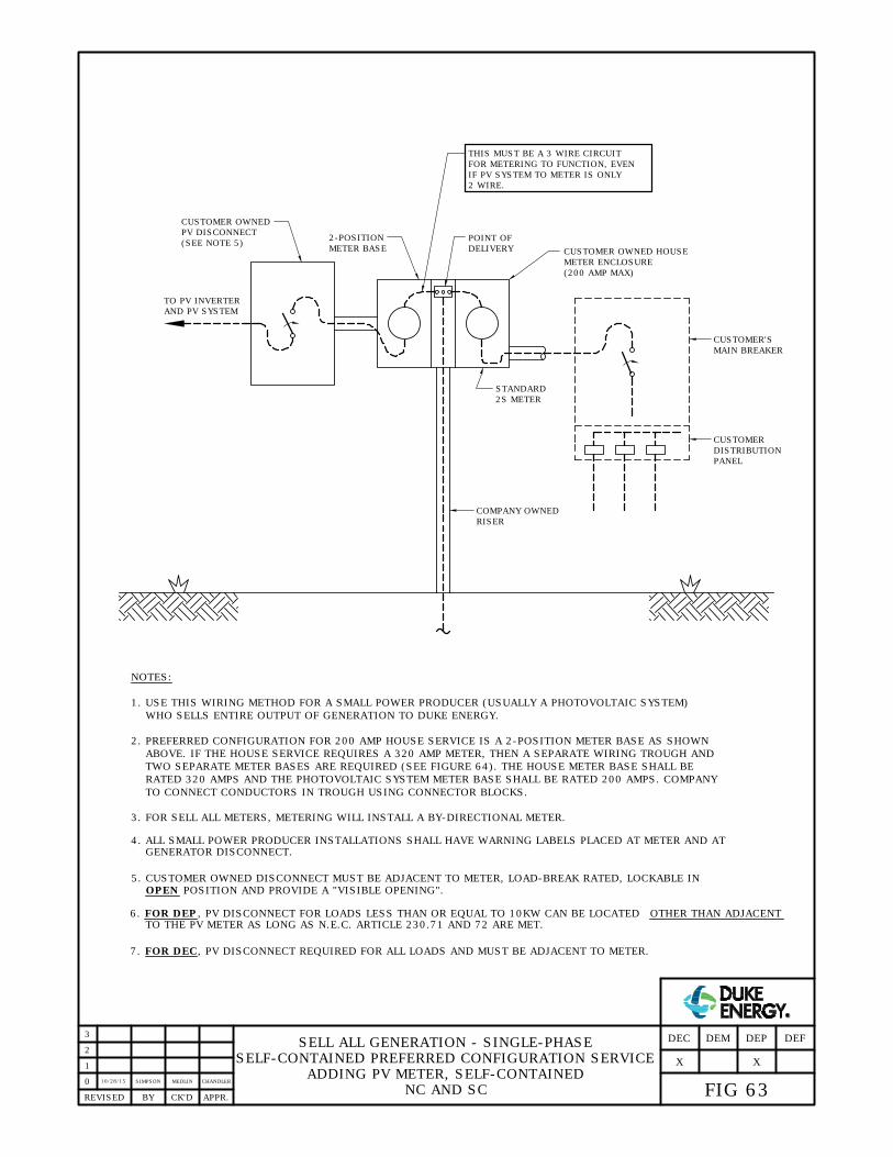
1. USE THIS WIRING METHOD FOR A SMALL POWER PRODUCER (USUALLY A PHOTOVOLTAIC SYSTEM)
WHO SELLS ENTIRE OUTPUT OF GENERATION TO DUKE ENERGY.
NOTES:
COMPANY OWNED
RISER
2-POSITION
METER BASE
TO CONNECT CONDUCTORS IN TROUGH USING CONNECTOR BLOCKS.
POINT OF
DELIVERY
3. FOR SELL ALL METERS, METERING WILL INSTALL A BY-DIRECTIONAL METER.
SELL ALL GENERATION - SINGLE-PHASE
SELF-CONTAINED PREFERRED CONFIGURATION SERVICE
ADDING PV METER, SELF-CONTAINED
NC AND SC
2 WIRE.
IF PV SYSTEM TO METER IS ONLY
FOR METERING TO FUNCTION, EVEN
THIS MUST BE A 3 WIRE CIRCUIT
0
APPR.REVISED BY CK'D
CUSTOMER OWNED HOUSE
METER ENCLOSURE
(200 AMP MAX)
2. PREFERRED CONFIGURATION FOR 200 AMP HOUSE SERVICE IS A 2-POSITION METER BASE AS SHOWN
ABOVE. IF THE HOUSE SERVICE REQUIRES A 320 AMP METER, THEN A SEPARATE WIRING TROUGH AND
TWO SEPARATE METER BASES ARE REQUIRED (SEE FIGURE 64). THE HOUSE METER BASE SHALL BE
RATED 320 AMPS AND THE PHOTOVOLTAIC SYSTEM METER BASE SHALL BE RATED 200 AMPS. COMPANY
STANDARD
2S METER
GENERATOR DISCONNECT.
4. ALL SMALL POWER PRODUCER INSTALLATIONS SHALL HAVE WARNING LABELS PLACED AT METER AND AT
5. CUSTOMER OWNED DISCONNECT MUST BE ADJACENT TO METER, LOAD-BREAK RATED, LOCKABLE IN
OPEN POSITION AND PROVIDE A "VISIBLE OPENING".
TO PV INVERTER
AND PV SYSTEM
CUSTOMER OWNED
PV DISCONNECT
(SEE NOTE 5)
1
CUSTOMER'S
MAIN BREAKER
CUSTOMER
DISTRIBUTION
PANEL
FIG 63
DEFDEP
X
DEMDEC
2
X
3
10/28/15SIMPSON MEDLIN CHANDLER
TO THE PV METER AS LONG AS N.E.C. ARTICLE 230.71 AND 72 ARE MET.
6. FOR DEP, PV DISCONNECT FOR LOADS LESS THAN OR EQUAL TO 10KW CAN BE LOCATED OTHER THAN ADJACENT
7. FOR DEC, PV DISCONNECT REQUIRED FOR ALL LOADS AND MUST BE ADJACENT TO METER.

1. USE THIS WIRING METHOD FOR A SMALL POWER PRODUCER (USUALLY A PHOTOVOLTAIC SYSTEM)
WHO SELLS ENTIRE OUTPUT OF GENERATION TO COMPANY.
NOTES:
EXISTING COMPANY
OWNED RISER
2. FOR SELL ALL CONFIGURATIONS, A BI-DIRECTIONAL METER WILL BE INSTALLED.
SELL ALL GENERATION - SINGLE-PHASE
SELF-CONTAINED ALTERNATE CONFIGURATION SERVICE
ADDING PV METER, SELF-CONTAINED
NC AND SC
1
0
APPR.REVISED BY CK'D
TO PV INVERTER
AND PV SYSTEM
CUSTOMER OWNED
PV DISCONNECT
CUSTOMER OWNED HOUSE
METER ENCLOSURE
(320 AMP MAX)
STANDARD
2S METER
GENERATOR DISCONNECT.
3. ALL SMALL POWER PRODUCER INSTALLATIONS SHALL HAVE WARNING LABELS PLACED AT METER AND AT
4. CUSTOMER'S ELECTRICIAN MUST MAKE ARRANGEMENTS WITH COMPANY FOR A CLEARANCE ON EXISTING
SERVICE, REMOVE COMPANY-OWNED RISER, INSTALL TROUGH AND RECONNECT RISER ABOVE AND BELOW
TROUGH.
5. COMPANY TO CONNECT CONDUCTORS IN TROUGH USING CONNECTOR BLOCKS.
CUSTOMER OWNED
METER ENCLOSURE
PV TOU METER
(BI-DIRECTIONAL)
POINT OF DELIVERY
CUSTOMER OWNED TROUGH
24" LONG X 12" TALL X
(SEE NOTE 6)
IS ONLY 2 WIRE.
EVEN IF PV SYSTEM TO METER
FOR METERING TO FUNCTION,
THIS MUST BE A 3 WIRE CIRCUIT
8" DEEP
CONDUCTORS
PROVIDED BY
CUSTOMER
SERVICE
MIN. CONDUCTOR SIZE
#1/0 AL/CU
2
6. CUSTOMER OWNED DISCONNECT MUST BE ADJACENT TO METER, LOAD-BREAK RATED, LOCKABLE IN
OPEN POSITION AND PROVIDE A "VISIBLE OPENING".
CUSTOMER'S
MAIN BREAKER
CUSTOMER
DISTRIBUTION
PANEL
FIG 64
DEFDEP
X
DEMDEC
9. PREFERRED CONFIGURATION FOR 200 AMP HOUSE SERVICE AND 200 AMP PV LOAD IS A 2-GANG METER
ENCLOSURE AS SHOWN IN FIGURE 63, BUT CUSTOMER MAY USE THIS ALTERNATE CONFIGURATION AS AN OPTION.
IF HOUSE SERVICE IS 320 AMP, THEN THIS ALTERNATE CONFIGURATION MUST BE UTILIZED FOR PV CONNECTION.
3
2/1/16SIMPSON MEDLIN CHANDLER
X
ADJACENT TO THE PV METER AS LONG AS N.E.C. ARTICLE 230.71 AND 72 ARE MET.
10. FOR VERY CONFINED SPACES (NO ROOM FOR TROUGH), CUSTOMER CAN INSTALL DOUBLE LUGS ON SOURCE SIDE
OF METER ENCLOSURE (SIZE #4 - 500 KCMIL) FOR COMPANY CONDUCTORS AND SIZED TO FIT PV CONDUCTORS.
7. FOR DEP, PV DISCONNECT FOR LOADS LESS THAN OR EQUAL TO 10KW CAN BE LOCATED OTHER THAN
8. FOR DEC, PV DISCONNECT REQUIRED FOR ALL LOADS AND MUST BE ADJACENT TO METER.

1. USE THIS WIRING METHOD FOR A SMALL POWER PRODUCER (USUALLY A PHOTOVOLTAIC SYSTEM)
WHO SELLS ENTIRE OUTPUT OF GENERATION TO COMPANY.
2. COMPANY TO CONNECT CONDUCTORS IN TROUGH USING CONNECTOR BLOCKS SHOWN ON FIGURE 21.
NOTES:
COMPANY OWNED
RISER
TO PV INVERTER
AND PV SYSTEM
CUSTOMER OWNED
PV DISCONNECT
CUSTOMER OWNED
PHOTOVOLTAIC SYSTEM
METER ENCLOSURE
(320 AMP MAX)
POINT OF
DELIVERY
(BI-DIRECTIONAL)
PV TOU METER
STANDARD
3S METER
3. FOR SELL ALL METERS, METERING WILL INSTALL A STANDARD METER PROGRAMMED FOR SGS-TOU
WITH ALL DATA REGISTERED AS RECEIVED.
SELL ALL GENERATION
SINGLE-PHASE T-RATED SERVICE
ADDING PV METER, SELF-CONTAINED
NC AND SC
IS ONLY 2 WIRE. MINIMUM
EVEN IF PV SYSTEM TO METER
FOR METERING TO FUNCTION,
THIS MUST BE A 3 WIRE CIRCUIT
0
APPR.REVISED BY CK'D
CT CABINET
TO CUSTOMER'S
MAIN BREAKER
(TYPICAL)
COMPANY
CT METER
GENERATOR DISCONNECT.
4. ALL SMALL POWER PRODUCER INSTALLATIONS SHALL HAVE WARNING LABELS PLACED AT METER AND AT
3' - 6'
MAX.
(SEE NOTE 5)
CUSTOMER OWNED TROUGH
24" LONG X 12" TALL X
8" DEEP
PROVIDED BY CUSTOMER
SERVICE CONDUCTORS
1
CONDUCTOR SIZE #1/0 AL/CU.
2
3
5. CUSTOMER OWNED DISCONNECT MUST BE ADJACENT TO METER, LOAD-BREAK RATED, LOCKABLE IN
OPEN POSITION AND PROVIDE A "VISIBLE OPENING".
FIG 65
DEFDEP
X
DEMDEC
X
10/28/15
SIMPSON MEDLIN CHANDLER
8. FOR EXISTING UG T-RATED SERVICE, CUSTOMER'S ELECTRICIAN MUST MAKE ARRANGEMENTS WITH COMPANY
FOR A CLEARANCE ON EXISTING SERVICE, REMOVE COMPANY SERVICE RISER, INSTALL TROUGH AND RISER TO
CT CABINET. POD IN TROUGH.
ADJACENT TO THE PV METER AS LONG AS N.E.C. ARTICLE 230.71 AND 72 ARE MET.
6. FOR DEP, PV DISCONNECT FOR LOADS LESS THAN OR EQUAL TO 10KW CAN BE LOCATED OTHER THAN
7. FOR DEC, PV DISCONNECT REQUIRED FOR ALL LOADS AND MUST BE ADJACENT TO METER.
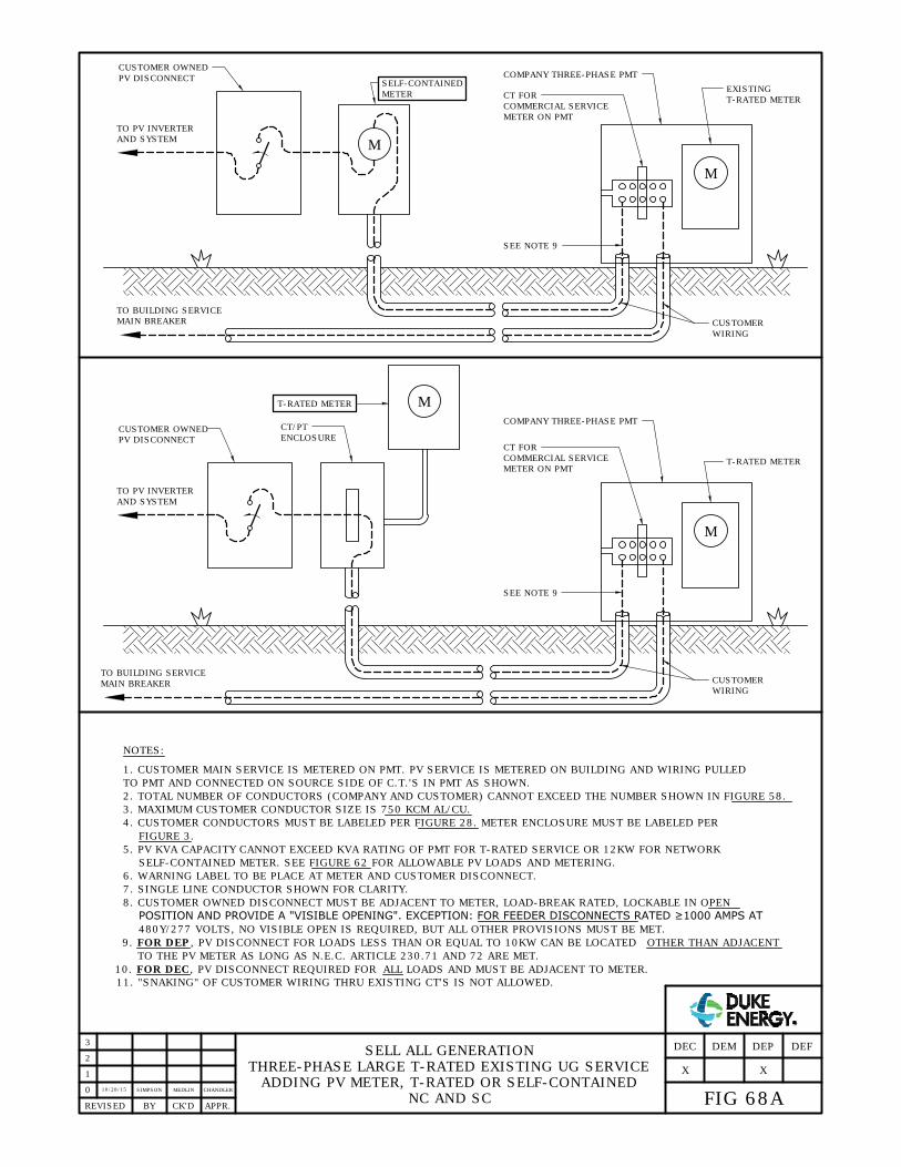
NOTES:
SELL ALL GENERATION
THREE-PHASE LARGE T-RATED EXISTING UG SERVICE
ADDING PV METER, T-RATED OR SELF-CONTAINED
NC AND SC
0
1
APPR.REVISED BY CK'D
TO PV INVERTER
AND SYSTEM
CUSTOMER OWNED
PV DISCONNECT
1. CUSTOMER MAIN SERVICE IS METERED ON PMT. PV SERVICE IS METERED ON BUILDING AND WIRING PULLED
TO PMT AND CONNECTED ON SOURCE SIDE OF C.T.'S IN PMT AS SHOWN.
2. TOTAL NUMBER OF CONDUCTORS (COMPANY AND CUSTOMER) CANNOT EXCEED THE NUMBER SHOWN IN FIGURE 58.
3. MAXIMUM CUSTOMER CONDUCTOR SIZE IS 750 KCM AL/CU.
4. CUSTOMER CONDUCTORS MUST BE LABELED PER FIGURE 28. METER ENCLOSURE MUST BE LABELED PER
FIGURE 3.
5. PV KVA CAPACITY CANNOT EXCEED KVA RATING OF PMT FOR T-RATED SERVICE OR 12KW FOR NETWORK
7. SINGLE LINE CONDUCTOR SHOWN FOR CLARITY.
TO BUILDING SERVICE
MAIN BREAKER
CT FOR
COMMERCIAL SERVICE
COMPANY THREE-PHASE PMT
CT/PT
ENCLOSURE
METER ON PMT
6. WARNING LABEL TO BE PLACE AT METER AND CUSTOMER DISCONNECT.
8. CUSTOMER OWNED DISCONNECT MUST BE ADJACENT TO METER, LOAD-BREAK RATED, LOCKABLE IN OPEN
POSITION AND PROVIDE A "VISIBLE OPENING". EXCEPTION: FOR FEEDER DISCONNECTS RATED ≥1000 AMPS AT
SELF-CONTAINED METER. SEE FIGURE 62 FOR ALLOWABLE PV LOADS AND METERING.
11. "SNAKING" OF CUSTOMER WIRING THRU EXISTING CT'S IS NOT ALLOWED.
M
MT-RATED METER
T-RATED METER
SEE NOTE 9
TO PV INVERTER
AND SYSTEM
CUSTOMER OWNED
PV DISCONNECT
TO BUILDING SERVICE
MAIN BREAKER
CT FOR
COMMERCIAL SERVICE
COMPANY THREE-PHASE PMT
SELF-CONTAINED
METER
METER ON PMT
CUSTOMER
WIRING
M
M
EXISTING
SEE NOTE 9
T-RATED METER
CUSTOMER
WIRING
2
FIG 68A
DEFDEP
X
DEMDEC
X
3
10/28/15
SIMPSON MEDLIN CHANDLER
TO THE PV METER AS LONG AS N.E.C. ARTICLE 230.71 AND 72 ARE MET.
480Y/277 VOLTS, NO VISIBLE OPEN IS REQUIRED, BUT ALL OTHER PROVISIONS MUST BE MET.
9. FOR DEP, PV DISCONNECT FOR LOADS LESS THAN OR EQUAL TO 10KW CAN BE LOCATED OTHER THAN ADJACENT
10. FOR DEC, PV DISCONNECT REQUIRED FOR ALL LOADS AND MUST BE ADJACENT TO METER.

SELL ALL GENERATION
THREE-PHASE LARGE T-RATED EXISTING OH SERVICE
ADDING PV METER, T-RATED OR SELF-CONTAINED
NC AND SC
0
APPR.REVISED BY CK'D
NOTES:
1. PV KVA CAPACITY CANNOT EXCEED KVA RATING OF OH BANK OR PLATFORM. REFER TO FIGURE 62 FOR METER
VOLTAGE STANDARD AND DEMAND LIMITS.
2. WARNING LABELS TO BE PLACED AT METER, CUSTOMER DISCONNECT AND TRANSFORMER POLE.
3. SINGLE LINE CONDUCTOR SHOWN FOR CLARITY.
CONNECT PV SECONDARY
METER ON SOURCE-SIDE
OF COMMERCIAL METER
PROPOSED SELL-ALL METER AND
COMPANY SECONDARY / SERVICE
(T-RATED METER ON POLE. IF
SELF-CONTAINED METER, MOUNT
ON BLDG. WALL)
CUSTOMER BUILDING
EXISTING COMPANY
OH FACILITIES
M
M
5. IF GENERATOR IS BEING ADDED WITHIN A SERVICE THAT UTILIZES SUBSTATION-STYLE TRANSFORMERS,
CONTACT DISTRIBUTION STANDARDS FOR GUIDANCE ON CONNECTION.
6. SERVICE LATERAL CLEARANCE MUST MEET FIG. 11 REQUIREMENTS.
OPERATING PERSONNEL , LOAD-BREAK RATED, LOCKABLE IN THE OPEN POSITION AND PROVIDE A "VISIBLE
4. CUSTOMER-OWNED DISCONNECT MUST BE ADJACENT TO METER, READILY ACCESSIBLE TO COMPANY
OH SERVICE - PV SEPARATE POD
OH SERVICE - PV RISER AT EXISTING RISER
1
2
FIG 68B
DEFDEP
X
DEMDEC
3
11/20/15
SIMPSON MEDLIN CHANDLER
REQUIRED FOR ALL LOADS AND MUST BE ADJACENT TO METER.
EXISTING SERVICE
METER
DUKE THREE-PHASE
OVERHEAD SERVICE
G
TO PV OR
OTHER
CUSTOMER
GENERATION
CUSTOMER OWNED
PV DISCONNECT
NEW PV METER
TO CUSTOMER
BREAKER
DUKE CURRENT TRANSFORMERS
PV SERVICE ENTRANCE
CONNECTED ON LINE
SIDE OF EXISTING CT'S
X
OPENING". FOR DEP, PV DISCONNECT FOR LOADS LESS THAN OR EQUAL TO 10KW CAN BE LOCATED OTHER THAN
ADJACENT TO THE PV METER AS LONG AS N.E.C. ARTICLE 230.71 AND 72 ARE MET. FOR DEC, PV DISCONNECT

NOTES:
SELL ALL GENERATION
STANDALONE SYSTEM
THREE-PHASE SECONDARY METERING
NC AND SC
0
1
APPR.REVISED BY CK'D
TO PV SYSTEM
INVERTER
1. THIS SERVICE ARRANGEMENT IS USED TO CONNECT TO A LARGE STANDALONE POWER PRODUCING
SYSTEM WHERE COMPANY PROVIDES TRANSFORMATION.
2. WARNING LABEL TO BE PLACED AT METER AND CUSTOMER DISCONNECT.
6. TOTAL CUSTOMER CONDUCTORS CANNOT EXCEED THAT SHOWN IN FIGURE 58.
7. MAXIMUM CUSTOMER CONDUCTOR SIZE IS 750 KCMIL AL/CU.
8. SINGLE LINE DIAGRAM SHOWN FOR CLARITY.
COMPANY FACILITIES
SEE DETAIL 'A'
POINT OF
DELIVERY
CUSTOMER
DISCONNECT
CUSTOMER WIRING
COMPANY FUSED
CUTOUT
COMPANY
METER
CT'S BY COMPANY
DETAIL 'A'
CUSTOMER
WIRING
POINT OF DELIVERY-
WHEN CUSTOMER
CONDUCTORS CONNECT
TO PMT
3. CUSTOMER OWNED DISCONNECT MUST BE ADJACENT TO METER, LOAD-BREAK RATED, LOCKABLE IN
OPEN POSITION AND PROVIDE A "VISIBLE OPENING". EXCEPTION: FOR FEEDER DISCONNECTS RATED ≥1000 AMPS
AT 480Y/277 VOLTS, NO VISIBLE OPEN IS REQUIRED, BUT ALL OTHER PROVISIONS MUST BE MET.
2
TO THE PV METER AS LONG AS N.E.C. ARTICLE 230.71 AND 72 ARE MET.
3
10/28/15
SIMPSON MEDLIN CHANDLER
FIG 69
DEFDEP
X
DEMDEC
X
4. FOR DEP, PV DISCONNECT FOR LOADS LESS THAN OR EQUAL TO 10KW CAN BE LOCATED OTHER THAN ADJACENT
5. FOR DEC, PV DISCONNECT REQUIRED FOR ALL LOADS AND MUST BE ADJACENT TO METER.

NOTES:
SELL ALL GENERATION
THREE-PHASE PRIMARY METERING
FUSED IPP INSTALLATION, CUSTOMER UG DIP
0
3
2
1
APPR.REVISED BY CK'D
TO PV SYSTEM
CUSTOMER WIRING
POINT OF DELIVERY ON
LOAD-SIDE TERMINAL OF
1. THIS SERVICE ARRANGEMENT IS USED TO CONNECT TO A LARGE IPP STANDALONE SYSTEM WHERE COMPANY
PROVIDES FUSING FOR PROTECTION. CUSTOMER RECEIVES PRIMARY VOLTAGE AND PROVIDES THEIR OWN
2. WARNING LABEL TO BE PLACED AT METER ON POLE ADVISING OF CUSTOMER GENERATION ON SITE.
3. CUSTOMER PROVIDES ALL WIRING AND TRANSFORMATION BEYOND LOAD SIDE TERMINALS OF COMPANY
DISCONNECT.
4. SINGLE LINE DIAGRAM SHOWN FOR CLARITY.
COMPANY FUSED
PRIMARY CT'S AND
PT'S BY COMPANY
DISCONNECT BY
COMPANY
COMPANY METER
COMPANY DISCONNECT
NEUTRAL
TRANSFORMATION AND UG FACILITIES.
5. COMPANY PROVIDES ALL FACILITIES TO P.O.D.
CUTOUT
10/28/15
SIMPSONSIMPSON ADCOCK
FIG 70A
DEFDEP
X
DEMDEC
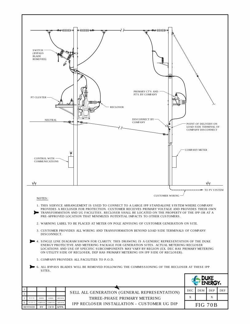
NOTES:
SELL ALL GENERATION (GENERAL REPRESENTATION)
THREE-PHASE PRIMARY METERING
IPP RECLOSER INSTALLATION - CUSTOMER UG DIP
0
3
2
1
APPR.REVISED BY CK'D
TO PV SYSTEM
CUSTOMER WIRING
POINT OF DELIVERY ON
LOAD-SIDE TERMINAL OF
1. THIS SERVICE ARRANGEMENT IS USED TO CONNECT TO A LARGE IPP STANDALONE SYSTEM WHERE COMPANY
PROVIDES A RECLOSER FOR PROTECTION. CUSTOMER RECEIVES PRIMARY VOLTAGE AND PROVIDES THEIR OWN
2. WARNING LABEL TO BE PLACED AT METER ON POLE ADVISING OF CUSTOMER GENERATION ON SITE.
3. CUSTOMER PROVIDES ALL WIRING AND TRANSFORMATION BEYOND LOAD SIDE TERMINALS OF COMPANY
DISCONNECT.
PRIMARY CT'S AND
PT'S BY COMPANY
DISCONNECT BY
COMPANY
COMPANY METER
COMPANY DISCONNECT
NEUTRAL
TRANSFORMATION AND UG FACILITIES. RECLOSER SHALL BE LOCATED ON THE PROPERTY OF THE IPP OR AT A
SWITCH
PT CLUSTER
CONTROL WITH
COMMUNICATIONS
RECLOSER
(BYPASS
BLADE
REMOVED)
10/28/15
SIMPSON SIMPSON ADCOCK
FIG 70B
DEFDEP
X
DEMDEC
4. SINGLE LINE DIAGRAM SHOWN FOR CLARITY. THIS DRAWING IS A GENERIC REPRESENTATION OF THE DUKE
5. COMPANY PROVIDES ALL FACILITIES TO P.O.D.
ENERGY PROTECTIVE AND METERING PACKAGE FOR GENERATION SITES. ACTUAL METERING/RECLOSER
LOCATIONS AND USE OF SPECIFIC SUBCOMPONENTS MAY VARY BY REGION (EX. DEC HAS PRIMARY METERING
ON UTILITY SIDE OF RECLOSER, DEP HAS PRIMARY METERING ON IPP SIDE OF RECLOSER).
6. ALL BYPASS BLADES WILL BE REMOVED FOLLOWING THE COMMISSIONING OF THE RECLOSER AT THESE IPP
SITES.
8/2/16
EANES
X
ADCOCKEANES
PRE-APPROVED LOCATION THAT MINIMIZES POTENTIAL IMPACTS TO OTHER CUSTOMERS.

NOTES:
SELL ALL GENERATION
THREE-PHASE PRIMARY METERING
FUSED IPP INSTALLATION - CUSTOMER OH CONNECTION
0
3
2
1
APPR.REVISED BY CK'D
POINT OF DELIVERY
1. THIS SERVICE ARRANGEMENT IS USED TO CONNECT TO A LARGE IPP STANDALONE SYSTEM WHEN COMPANY
PROVIDES FUSING FOR PROTECTION. CUSTOMER RECEIVES PRIMARY VOLTAGE AND PROVIDES THEIR OWN
2. WARNING LABEL TO BE PLACED AT METER ON POLE ADVISING OF CUSTOMER GENERATION ON SITE.
3. CUSTOMER PROVIDES ALL WIRING, DISCONNECTS AND TRANSFORMATION BEYOND POINT OF DELIVERY.
4. SINGLE LINE DIAGRAM SHOWN FOR CLARITY.
COMPANY FUSED CUTOUT
PRIMARY CT'S AND
PT'S BY COMPANY
COMPANY METER
CUSTOMER-OWNED
FACILITIES
TO PV SYSTEM
TRANSFORMATION AND OH FACILITIES.
5. COMPANY PROVIDES ALL FACILITIES TO P.O.D.
10/28/15
SIMPSON SIMPSON ADCOCK
FIG 71A
DEFDEP
X
DEMDEC

NOTES:
SELL ALL GENERATION (GENERAL REPRESENTATION)
THREE-PHASE PRIMARY METERING
IPP RECLOSER INSTALLATION - CUSTOMER OH CONNECTION
0
3
2
1
APPR.REVISED BY CK'D
POINT OF DELIVERY
1. THIS SERVICE ARRANGEMENT IS USED TO CONNECT TO A LARGE IPP STANDALONE SYSTEM WHERE COMPANY
PROVIDES A RECLOSER FOR PROTECTION. CUSTOMER RECEIVES PRIMARY VOLTAGE AND PROVIDES THEIR OWN
2. WARNING LABEL TO BE PLACED AT METER ON POLE ADVISING OF CUSTOMER GENERATION ON SITE.
3. CUSTOMER PROVIDES ALL WIRING, DISCONNECTS AND TRANSFORMATION BEYOND POINT OF DELIVERY.
4. SINGLE LINE DIAGRAM SHOWN FOR CLARITY. THIS DRAWING IS A GENERIC REPRESENTATION OF THE DUKE
PRIMARY CT'S AND
PT'S BY COMPANY
COMPANY METER
CUSTOMER-OWNED
FACILITIES
NEUTRAL
5. COMPANY PROVIDES ALL FACILITIES TO P.O.D.
PT CLUSTER
RECLOSER
TO PV SYSTEM
TRANSFORMATION AND OH FACILITIES. RECLOSER SHALL BE LOCATED ON THE PROPERTY OF THE IPP OR AT A
CONTROL WITH
COMMUNICATIONS
SWITCH
(BYPASS
BLADE
REMOVED)
10/28/15
SIMPSON SIMPSON ADCOCK
FIG 71B
DEFDEP
X
DEMDEC
ENERGY PROTECTIVE AND METERING PACKAGE FOR GENERATION SITES. ACTUAL METERING/RECLOSER
LOCATIONS AND USE OF SPECIFIC SUBCOMPONENTS MAY VARY BY REGION (EX. DEC HAS PRIMARY METERING
ON UTILITY SIDE OF RECLOSER, DEP HAS PRIMARY METERING ON IPP SIDE OF RECLOSER).
6. ALL BYPASS BLADES WILL BE REMOVED FOLLOWING THE COMMISSIONING OF THE RECLOSER AT THESE IPP
SITES.
X
8/2/16
EANESADCOCKEANES
PRE-APPROVED LOCATION THAT MINIMIZES POTENTIAL IMPACTS TO OTHER CUSTOMERS.
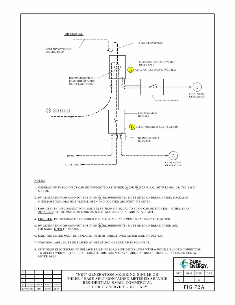
0
APPR.REVISED BY CK'D
"NET" GENERATION METERING SINGLE OR
THREE-PHASE SELF-CONTAINED METERED SERVICE
RESIDENTIAL/ SMALL COMMERCIAL
OH OR UG SERVICE - NC ONLY
G
OH SERVICE
M
CUSTOMER SELF-CONTAINED
EXISTING MAIN
HVAC
SERVICE ENTRANCE
METER BASE
BREAKER
COMPANY OVERHEAD
SERVICE DROP
BRANCH CIRCUIT
BREAKERS
NOTES:
1. GENERATION DISCONNECT CAN BE CONNECTED AT EITHER A OR B PER N.E.C. ARTICLE 690.64, 705.12(A)
2. PV GENERATION DISCONNECT POSITION A REQUIREMENTS: MUST BE LOAD-BREAK RATED, LOCKABLE
OPEN POSITION, PROVIDE VISIBLE OPEN AND LOCATED ADJACENT TO METER.
6. EXISTING METER MUST BE REPLACED WITH BI-DIRECTIONAL METER (SEE FIGURE 62).
7. WARNING LABEL MUST BE PLACED AT METER AND GENERATOR DISCONNECT.
5. PV GENERATION DISCONNECT POSITION B REQUIREMENTS: MUST BE LOAD-BREAK RATED AND
LOCKABLE OPEN PROVISION.
OR (D).
ADJACENT TO THE METER AS LONG AS N.E.C. ARTICLE 230.71 AND 72 ARE MET.
PV OR OTHER
GENERATION
PV DISCONNECT
A
DOUBLE-LUGGED ON
LOAD SIDE OF METER
OR INSTALL TROUGH
OR
B
G
PV OR OTHER
GENERATION
STOVE, ETC.
N.E.C. ARTICLE 690.64, 705.12(D)
8. CUSTOMER ELECTRICIAN TO REPLACE EXISTING LOAD SIDE METER LUGS WITH A DOUBLE-LUGGED CONNECTOR
TO ACCEPT WIRING. IF CORRECT CONNECTORS ARE NOT AVAILABLE, A TROUGH MUST BE INSTALLED BELOW
METER BASE.
N.E.C. ARTICLE 690.64, 705.12(A)
1
U
U
U
UG SERVICE
2
FIG 72A
DEFDEP
X
DEMDEC
3
10/28/15SIMPSON MEDLIN CHANDLER
X
3. FOR DEP, PV DISCONNECT FOR LOADS LESS THAN OR EQUAL TO 10KW CAN BE LOCATED OTHER THAN
4. FOR DEC, PV DISCONNECT REQUIRED FOR ALL LOADS AND MUST BE ADJACENT TO METER.

0
1
APPR.REVISED BY CK'D
"NET" GENERATION METERING
SINGLE OR THREE-PHASE C.T. METERED SERVICE
RESIDENTIAL/SMALL COMMERCIAL
UG SERVICE - NC ONLY
FIG 72B
DEFDEP
X
DEMDEC
NOTES:
1. GENERATION DISCONNECT CAN BE CONNECTED AT EITHER A OR B PER N.E.C. ARTICLE 690.64, 705.12(A)
2. PV GENERATION DISCONNECT POSITION A REQUIREMENTS: MUST BE LOAD-BREAK RATED, LOCKABLE
OPEN POSITION, PROVIDE VISIBLE OPEN AND LOCATED ADJACENT TO METER.
6. EXISTING METER MUST BE REPLACED WITH BI-DIRECTIONAL METER. SEE FIGURE 62.
5. PV GENERATION DISCONNECT POSITION B REQUIREMENTS: MUST BE LOAD-BREAK RATED AND
LOCKABLE OPEN PROVISION.
OR (D).
TO THE METER AS LONG AS N.E.C. ARTICLE 230.71 AND 72 ARE MET.
2
G
M
PV DISCONNECT
A
B
N.E.C. ARTICLE 690.64, 705.12(D)
N.E.C. ARTICLE 690.64, 705.12(A)
CT CABINET
COMPANY
CT METER
CUSTOMER'S
MAIN BREAKER
CT
BREAKER
CIRCUIT
G
TO PV OR OTHER
CUSTOMER GENERATION
TO PV OR
OTHER
CUSTOMER
GENERATION
7. WARNING LABEL MUST BE PLACED AT METER AND GENERATOR DISCONNECT.
8. FOR CONNECTION A, CUSTOMER ELECTRICIAN TO REPLACE EXISTING SOURCE SIDE CONNECTORS ON
CUSTOMER MAIN BREAKER WITH A DOUBLE-LUGGED CONNECTOR TO ACCEPT WIRING. IF CORRECT
CONNECTORS ARE NOT AVAILABLE, A TROUGH MUST BE INSTALLED ON SOURCE SIDE OF CUSTOMER MAIN
BREAKER AND PV DISCONNECT.
CUSTOMER
WIRING
COMAPNY RISER
AND CONDUCTORS
3
10/28/15SIMPSON MEDLIN CHANDLER
X
4. FOR DEC, PV DISCONNECT REQUIRED FOR ALL LOADS AND MUST BE ADJACENT TO METER.
3. FOR DEP, PV DISCONNECT FOR LOADS LESS THAN OR EQUAL TO 10KW CAN BE LOCATED OTHER THAN ADJACENT
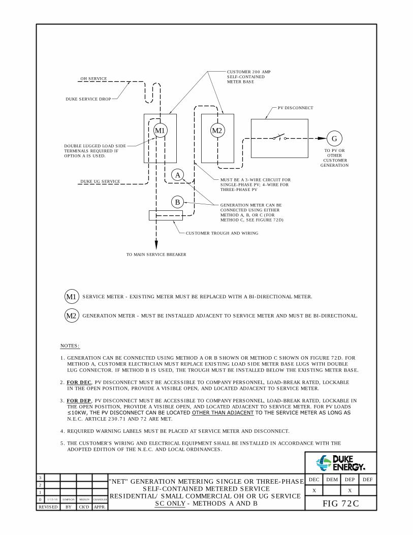
0
1
APPR.REVISED BY CK'D
"NET" GENERATION METERING SINGLE OR THREE-PHASE
SELF-CONTAINED METERED SERVICE
RESIDENTIAL/ SMALL COMMERCIAL OH OR UG SERVICE
SC ONLY - METHODS A AND B
FIG 72C
DEFDEP
X
DEMDEC
2
G
M1
PV DISCONNECT
TO PV OR
OTHER
CUSTOMER
GENERATION
3
1/13/16SIMPSON MEDLIN CHANDLER
X
NOTES:
1. GENERATION CAN BE CONNECTED USING METHOD A OR B SHOWN OR METHOD C SHOWN ON FIGURE 72D. FOR
METHOD A, CUSTOMER ELECTRICIAN MUST REPLACE EXISTING LOAD SIDE METER BASE LUGS WITH DOUBLE
LUG CONNECTOR. IF METHOD B IS USED, THE TROUGH MUST BE INSTALLED BELOW THE EXISTING METER BASE.
IN THE OPEN POSITION, PROVIDE A VISIBLE OPEN, AND LOCATED ADJACENT TO SERVICE METER.
4. REQUIRED WARNING LABELS MUST BE PLACED AT SERVICE METER AND DISCONNECT.
5. THE CUSTOMER'S WIRING AND ELECTRICAL EQUIPMENT SHALL BE INSTALLED IN ACCORDANCE WITH THE
ADOPTED EDITION OF THE N.E.C. AND LOCAL ORDINANCES.
M2
M1
SERVICE METER - EXISTING METER MUST BE REPLACED WITH A BI-DIRECTIONAL METER.
M2
GENERATION METER - MUST BE INSTALLED ADJACENT TO SERVICE METER AND MUST BE BI-DIRECTIONAL.
DUKE UG SERVICE
DOUBLE LUGGED LOAD SIDE
TERMINALS REQUIRED IF
OPTION A IS USED.
DUKE SERVICE DROP
OH SERVICE
A
B
TO MAIN SERVICE BREAKER
CUSTOMER TROUGH AND WIRING
MUST BE A 3-WIRE CIRCUIT FOR
SINGLE-PHASE PV; 4-WIRE FOR
THREE-PHASE PV
GENERATION METER CAN BE
CONNECTED USING EITHER
METHOD A, B, OR C (FOR
METHOD C, SEE FIGURE 72D)
CUSTOMER 200 AMP
SELF-CONTAINED
METER BASE
THE OPEN POSITION, PROVIDE A VISIBLE OPEN, AND LOCATED ADJACENT TO SERVICE METER. FOR PV LOADS
≤10KW, THE PV DISCONNECT CAN BE LOCATED OTHER THAN ADJACENT TO THE SERVICE METER AS LONG AS
N.E.C. ARTICLE 230.71 AND 72 ARE MET.
2. FOR DEC, PV DISCONNECT MUST BE ACCESSIBLE TO COMPANY PERSONNEL, LOAD-BREAK RATED, LOCKABLE
3. FOR DEP, PV DISCONNECT MUST BE ACCESSIBLE TO COMPANY PERSONNEL, LOAD-BREAK RATED, LOCKABLE IN

0
1
APPR.REVISED BY CK'D
"NET" GENERATION METERING SINGLE OR THREE-PHASE
SELF-CONTAINED METERED SERVICE
RESIDENTIAL/ SMALL COMMERCIAL OH OR UG SERVICE
SC ONLY - METHOD C
FIG 72D
DEFDEP
X
DEMDEC
2
G
M1
PV DISCONNECT
TO PV OR
OTHER
CUSTOMER
GENERATION
3
10/28/15SIMPSON MEDLIN CHANDLER
X
NOTES:
IN THE OPEN POSITION PROVIDING A VISIBLE OPEN, AND LOCATED ADJACENT TO THE SERVICE METER.
2. REQUIRED WARNING LABELS MUST BE PLACED AT SERVICE METER AND DISCONNECT.
3. THE CUSTOMER'S WIRING AND ELECTRICAL EQUIPMENT SHALL BE INSTALLED IN ACCORDANCE WITH THE
ADOPTED EDITION OF THE N.E.C. AND LOCAL ORDINANCES.
M2
M1
SERVICE METER - EXISTING METER MUST BE REPLACED WITH A BI-DIRECTIONAL METER.
M2
GENERATION METER - MUST BE INSTALLED ADJACENT TO SERVICE METER AND MUST BE BI-DIRECTIONAL.
DUKE UG SERVICE
DUKE SERVICE DROP
OH SERVICE
MUST BE A 3-WIRE CIRCUIT FOR
SINGLE-PHASE PV; 4-WIRE FOR
THREE-PHASE
CUSTOMER 200 AMP
SELF-CONTAINED
METER BASE
MAIN SERVICE BREAKER
BRANCH CIRCUIT BREAKER
SERVICE ENTRANCE PANEL
FOR LOAD ≤10 KW CAN BE LOCATED OTHER THAN ADJACENT TO THE METER AS LONG AS N.E.C. ARTICLE 230.71
AND 72 ARE MET.
C
METHOD
1. FOR DEC: THE PV DISCONNECT MUST BE ACCESSIBLE TO COMPANY PERSONNEL, LOAD-BREAK RATED LOCKABLE
FOR DEP: THE BRANCH CIRCUIT BREAKER MUST BE LOAD-BREAK RATED AND LOCKABLE OPEN. PV DISCONNECT

0
1
APPR.REVISED BY CK'D
FIG 72E
DEFDEP
X
DEMDEC
2
GENERATOR
CUSTOMER'S
MAIN BREAKER
TO CUSTOMER LOAD
CUSTOMER
ELECTRIC
COMPANY ELECTRIC
SERVICE WIRING
3
X
8/3/16ARCHER MEDLIN CHANDLER
POD
CT CABINET
GENERATOR METER;
SEE NOTE 5
CT
GENERATOR
WIRING
GENERATOR
TROUGH AND
CONNECTORS
G
TO GENERATION
"NET METERING" GENERATION
WITH CT METERED ELECTRIC SERVICE
WITH GENERATOR DISCONNECT RATED >400 AMPS
SOUTH CAROLINA ONLY
2. GENERATOR DISCONNECT, LOAD-BREAK RATED, LOCKABLE OPEN. PROVIDE VISIBLE OPEN AND LOCATE
ADJACENT TO GENERATOR CT CABINET.
3. BOTH COMPANY METERS MUST BE BI-DIRECTIONAL.
4. DUKE WILL PLACE GENERATION WARNING LABELS AT BOTH METERS AND GENERATOR DISCONNECTS.
5. DUKE PROVIDES AND INSTALLS GENERATOR METER AND ENCLOSURE. DUKE PROVIDES GENERATOR CT'S.
6. GENERATOR CT CABINET REQUIRED WHEN GENERATOR PROTECTIVE DEVICE IS GREATER THAN 400 AMPS.
LOCATE ADJACENT TO ELECTRIC SERVICE METER.
7. COMPANY ELECTRIC SERVICE CT'S MAY BE IN A PADMOUNT TRANSFORMER, CT CABINET MOUNTED ON THE
BUILDING, A MAST, OR UTILITY POLE. (NOTE: DEP: PROVIDES CT CABINET; SEE FIGURE 43B. DEC: CUSTOMER
T-RATED SERVICE;
SEE NOTE 7
M1
ELECTRIC
SERVICE
METER
CUSTOMER
SERVICE
WIRING
M2
GENERATOR
DISCONNECT
CT
A
B
C
NOTES:
1. GENERATOR DISCONNECT CAN BE CONNECTED AT EITHER A , B , OR C .
PROVIDES CABINET; SEE FIGURE 43A.) FOR INSTANCES WHERE SERVICE IS PROVIDED BY A PADMOUNT
TRANSFORMER, THE GENERATOR WIRING MAY BE CONNECTED WITHIN THE SECONDARY COMPARTMENT OF THE
TRANSFORMER ONLY IF THERE IS ADEQUATE SPACE AVAILABLE ON THE TRANSFORMER SPADES AND THE
CRITERIA PER FIGURE 58 IS NOT EXCEEDED. THIS EXCEPTION MUST BE VERIFIED IN THE
FIELD PRIOR TO ANY FINAL DESIGN APPROVAL.

0
1
APPR.REVISED BY CK'D
"NET METERING" GENERATION
WITH CT METERED ELECTRIC SERVICE
SOUTH CAROLINA ONLY
FIG 72F
DEFDEP
X
DEMDEC
NOTES:
1. GENERATOR DISCONNECT CAN BE CONNECTED AT EITHER A , B , OR C .
2. GENERATOR DISCONNECT REQUIREMENTS: MUST BE LOAD-BREAK RATED, LOCKABLE OPEN POSITION, PROVIDE
VISIBLE OPEN AND LOCATED ADJACENT TO ELECTRIC SERVICE METER.
5. BOTH METERS MUST BE BI-DIRECTIONAL METER.
4. FOR OPTION B , IF VOLTAGE IS 480/277, CIRCUIT BREAKER MUST BE LOAD-BREAK RATED AND LOCKABLE OPEN
PROVISION OR MAY INSERT GENERATION METER DISCONNECT BETWEEN BREAKER AND GENERATOR METER.
ADJACENT TO THE ELECTRIC SERVICE METER AS LONG AS N.E.C. GUIDELINES ARE MET.
2
G
M1
GENERATOR DISCONNECT
A
B
CUSTOMER'S
MAIN BREAKER
CT
CIRCUIT
BREAKER
TO GENERATION
6. DUKE WILL PLACE GENERATION WARNING LABELS AT BOTH METERS AND GENERATOR DISCONNECTS.
3
8/3/16ARCHER MEDLIN CHANDLER
X
3. FOR DEP ONLY, DISCONNECT FOR GENERATION LESS THAN OR EQUAL TO 10KW CAN BE LOCATED OTHER THAN
M2
DISCONNECT
MUST BE A 3-WIRE CIRCUIT FOR
SINGLE-PHASE PV; 4-WIRE
G
GENERATOR DISCONNECT
TO GENERATION
M2
FOR THREE-PHASE PV
GENERATOR
SELF-CONTAINED
METER BASE;
MUST BE A 3-WIRE CIRCUIT FOR
SINGLE-PHASE PV; 4-WIRE
FOR THREE-PHASE PV
SEE NOTE 7
7. THIS DISCONNECT IS REQUIRED ONLY ON 480/277V, THREE-PHASE GENERATOR SELF-CONTAINED METER
T-RATED SERVICE;
SEE NOTE 10
POD
METER
CUSTOMER ELECTRIC
SERVICE WIRING
C
COMPANY ELECTRIC
SERVICE WIRING
ELECTRIC
SERVICE
METER
CUSTOMER GENERATOR
TROUGH AND CONNECTORS
GENERATOR SELF-CONTAINED
METER BASE SEE NOTE 9
APPLICATIONS.
8. DUKE PROVIDES AND INSTALLS GENERATOR METER.
9. A GENERATOR SELF-CONTAINED METER BASE IS REQUIRED WHEN THE LARGEST SIZED GENERATION
PROTECTION DEVICE DOES NOT EXCEED 400 AMPS. LOCATE ADJACENT TO ELECTRIC SERVICE METER.
10. COMPANY ELECTRIC SERVICE CT'S MAY BE IN A PADMOUNT TRANSFORMER, CT CABINET MOUNTED ON THE
BUILDING, A MAST OR UTILITY POLE. FOR INSTANCES WHERE SERVICE IS PROVIDED BY A PADMOUNT
GENERATOR
SEE NOTE 9
TRANSFORMER, THE GENERATOR WIRING MAY BE CONNECTED WITHIN THE SECONDARY COMPARTMENT OF THE
TRANSFORMER ONLY IF THERE IS ADEQUATE SPACE AVAILABLE ON THE TRANSFORMER SPADES AND THE
CRITERIA PER FIGURE 58 IS NOT EXCEEDED. THIS EXCEPTION MUST BE VERIFIED IN THE FIELD PRIOR TO ANY
FINAL DESIGN APPROVAL.
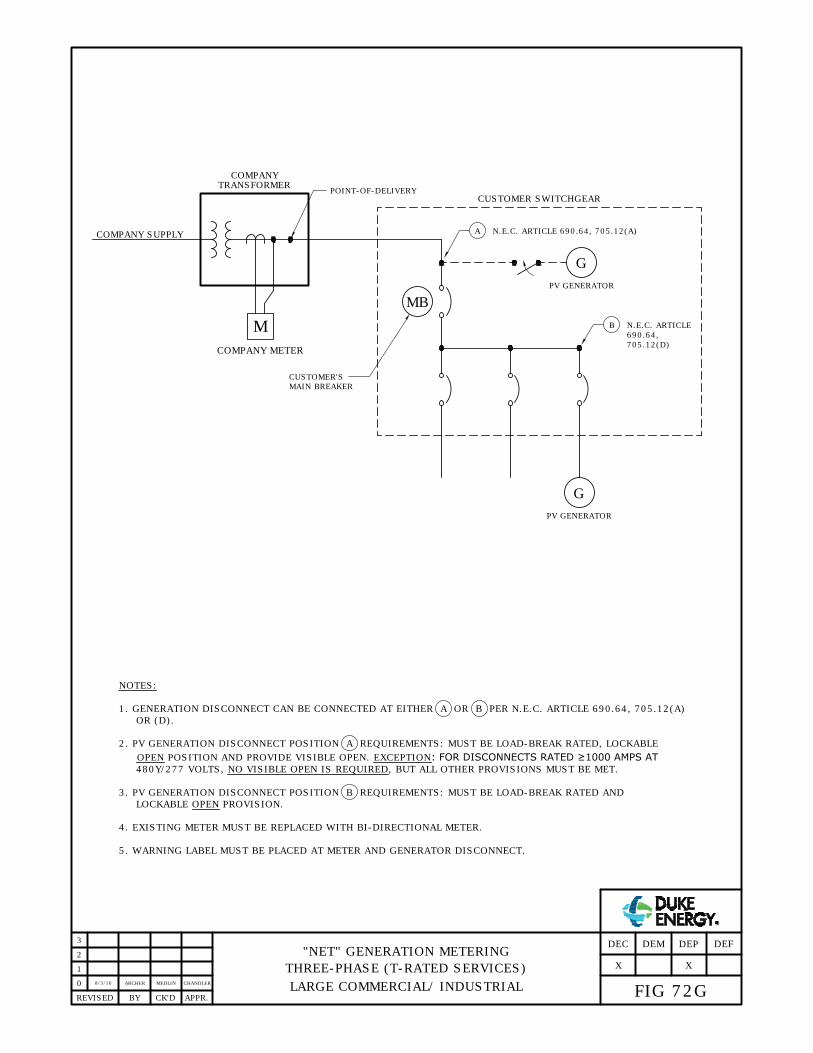
0
1
APPR.REVISED BY CK'D
8/3/16MEDLINARCHER CHANDLER
2
3
FIG 72G
DEFDEP
X
DEMDEC
G
NOTES:
"NET" GENERATION METERING
THREE-PHASE (T-RATED SERVICES)
LARGE COMMERCIAL/ INDUSTRIAL
1. GENERATION DISCONNECT CAN BE CONNECTED AT EITHER A OR B PER N.E.C. ARTICLE 690.64, 705.12(A)
2. PV GENERATION DISCONNECT POSITION A REQUIREMENTS: MUST BE LOAD-BREAK RATED, LOCKABLE
480Y/277 VOLTS, NO VISIBLE OPEN IS REQUIRED, BUT ALL OTHER PROVISIONS MUST BE MET.
OPEN POSITION AND PROVIDE VISIBLE OPEN. EXCEPTION: FOR DISCONNECTS RATED ≥1000 AMPS AT
4. EXISTING METER MUST BE REPLACED WITH BI-DIRECTIONAL METER.
5. WARNING LABEL MUST BE PLACED AT METER AND GENERATOR DISCONNECT.
COMPANY METER
POINT-OF-DELIVERY
PV GENERATOR
G
A
B
N.E.C. ARTICLE 690.64, 705.12(A)
N.E.C. ARTICLE
CUSTOMER SWITCHGEAR
M
COMPANY SUPPLY
TRANSFORMER
PV GENERATOR
MB
CUSTOMER'S
MAIN BREAKER
3. PV GENERATION DISCONNECT POSITION B REQUIREMENTS: MUST BE LOAD-BREAK RATED AND
LOCKABLE OPEN PROVISION.
OR (D).
690.64,
COMPANY
X
705.12(D)

CUSTOMER ATS
TO FACILITY LOADS
52U
52G
M
COMPANY SOURCE
COMPANY TRANSFORMER
LEGEND:
G
GENERATOR
M
METER
ATS
AUTO-TRANSFER SWITCH
UTILITY-SIDE BREAKER WITH
GENERATOR-SIDE BREAKER
G
TO MEET THE FOLLOWING SPECIFICATIONS:
0
3
2
1
APPR.REVISED BY CK'D
LOCKABLE OPEN FEATURE
GROUNDING PROVISION PROVIDED BY CUSTOMER
A. ACCESSIBLE TO COMPANY PERSONNEL
52U
52G
SERVICE WITH STANDBY GENERATION
AUTO TRANSFER SWITCH
PARALLEL (>100 MILLISECONDS)
TOTAL FACILITY LOAD
B. 10' CLEARANCE
C. GROUND BALL STUD(S) ON EACH PHASE AND NEUTRAL
1. MOUNTED IN HORIZONTAL POSITION
2. 25MM OR 30MM DIAMETER
3. 4" MIN. LENGTH, INCLUDING BALL
4. FAULT CURRENT RATED FOR GEAR BUSS.
5. MULTIPLE GROUND BALL STUDS MAY BE NEEDED
TO MEET AVAILABLE FAULT CURRENT.
10/28/15SIMPSONSIMPSON ADCOCK
FIG 73A
DEFDEP
X
DEMDEC
XX X

0
3
2
1
APPR.REVISED BY CK'D
STANDBY GENERATION - PROTECTION REQUIREMENTS
(SOFT LOAD TRANSITION
>100 MILLISECONDS PARALLEL TIME)
FIG 73B
DEFDEP
X
DEMDEC
XXX
10/28/15SIMPSONVALENTIN ADCOCK
INTERCONNECTION EVALUATION
SYSTEMS IN THIS CATEGORY REQUIRE APPROVAL IN WRITING FROM DUKE ENERGY BEFORE BEING CONNECTED.
SPECIFICALLY, INTERCONNECTION OF GENERATING FACILITIES IN THIS CATEGORY MUST BE EVALUATED AND
APPROVED BY THE DISTRIBUTION PROTECTION AUTOMATION AND CONTROL GROUP WITHIN DUKE ENERGY.
INTERCONNECTION PROTECTION (RELAYING) REQUIREMENTS
FOR INTERCONNECTION PROTECTION, THE GENERATING FACILITY'S INTERCONNECTION EQUIPMENT MUST
EITHER BE LISTED AS FULLY COMPLIANT WITH UL1741 (FOR INVERTER-BASED EQUIPMENT) OR MUST BE
COMPLIANT WITH IEEE 1547 SECTION 4 (INTERCONNECTION TECHNICAL SPECIFICATIONS AND
REQUIREMENTS. ADDITIONAL REQUIREMENTS ARE LISTED BELOW:
1. THE DER UNIT SHALL PARALLEL WITH THE AREA COMPANY DISTRIBUTION SYSTEM WITHOUT CAUSING A
VOLTAGE FLUCTUATION AT THE POD GREATER THAN +/-5% OF THE PREVAILING VOLTAGE LEVEL OF THE
COMPANY DISTRIBUTION SYSTEM AT THE POD. (IEEE 1547-2003 SECTION 4.1.3 SYNCHRONIZATION)
2. THE DER UNIT SHALL NOT ENERGIZE THE COMPANY DISTRIBUTION SYSTEM WHEN THE AREA COMPANY
DISTRIBUTION SYSTEM IS DE-ENERGIZED. (IEEE 1547-2003 SECTION 4.1.5 INADVERTENT ENERGIZATION
3. INTERCONNECTION PROTECTION RELAYING MUST MEASURE VOLTAGES ON THE “UTILITY” SIDE OF 52U.
RELAY VOLTAGE INPUTS MUST BE FROM THREE SEPARATE PHASE-TO-GROUND VOLTAGES (FOR 4-WIRE
SERVICES) OR FROM THREE SEPARATE PHASE-TO-PHASE VOLTAGES (FOR 3-WIRE SERVICES). REVERSE
POWER RELAY (32R) MUST MEASURE CURRENT AT THE 52U BREAKER.
4. INTERCONNECTION PROTECTION RELAYING MUST HAVE FIVE PROTECTIVE ELEMENTS LISTED BELOW WITH
SETTINGS AS SPECIFIED:
A. 27 (UNDER VOLTAGE): 0.88 PER UNIT, 10 CYCLE TIME DELAY
B. 59 (OVER VOLTAGE): 1.10 PER UNIT, 10 CYCLE TIME DELAY
C. 81U (UNDER FREQUENCY): 59.5 HZ, 10 CYCLE TIME DELAY
D. 81O (OVER FREQUENCY): 60.5 HZ, 10 CYCLE TIME DELAY
E. 32R (REVERSE POWER): WATTS SET AT 5% OF TOTAL GENERATING CAPACITY, WITH A 1.0 SECOND
TIME DELAY
5. INTERCONNECTION PROTECTION RELAY TRIP FUNCTIONS MUST CAUSE SEPARATION OF THE GENERATION
FROM THE UTILITY, EITHER BY (1) TRIPPING ALL GENERATORS [52G] BREAKERS OR BY (2) TRIPPING ALL
UTILITY MAIN [52U] BREAKERS.
6. SERVICE ENTRANCE DISCONNECTING EQUIPMENT WITH VISIBLE OPENING CAPABILITY AND GROUNDING
PROVISIONS. THIS INCLUDES THE ABILITY TO LOCK OPEN OR “RACK-OUT” THEIR UTILITY BREAKER OR
SERVICE ENTRANCE DISCONNECT.
7. THE INTERCONNECTION PROTECTION EQUIPMENT MUST HAVE A SYNCHRONIZATION CHECK FUNCTION (25
RELAY).
8. CUSTOMER MUST PROVIDE A DOCUMENT STAMPED BY A LICENSED PROFESSIONAL ENGINEER (LICENSED
IN THE STATE WHERE THE GENERATING FACILITY IS TO BE LOCATED) SHOWING APPROVAL OF CUSTOMER'S
DESIGN AND TESTING OF SYSTEM OPERATION MEETS DUKE ENERGY REQUIREMENTS FOR MOMENTARY
PARALLEL OPERATION.
9. CUSTOMER MUST SIGN AN INTERCONNECTION AGREEMENT BEFORE MOMENTARY PARALLEL OPERATION IS
ALLOWED.
OF THE AREA COMPANY DISTRIBUTION SYSTEM)

FIG 74
7/2/15VALENTIN SIMPSON ADCOCK
STANDBY GENERATION - PROTECTION REQUIREMENTS
MOMENTARY PARALLEL GENERATION
(FAST TRANSITION ≤100 MILLISECONDS PARALLEL TIME)
REVISED CK'DBY APPR.
1
0
3
2
DEFDEP
X
DEMDEC
SYSTEMS IN THIS CATEGORY REQUIRE APPROVAL IN WRITING FROM DUKE ENERGY BEFORE BEING CONNECTED.
SPECIFICALLY, INTERCONNECTION OF GENERATING FACILITIES IN THIS CATEGORY MUST BE EVALUATED AND
APPROVED BY THE DISTRIBUTION PROTECTION AUTOMATION AND CONTROL GROUP WITHIN DUKE ENERGY.
INTERCONNECTION PROTECTION (RELAYING) REQUIREMENTS
INTERCONNECTION EVALUATION
XX X
FOR INTERCONNECTION PROTECTION, THE GENERATING FACILITY'S INTERCONNECTION EQUIPMENT MUST
EITHER BE LISTED AS FULLY COMPLIANT WITH UL1741 (FOR INVERTER-BASED EQUIPMENT) OR MUST BE
COMPLIANT WITH IEEE 1547 SECTION 4 (INTERCONNECTION TECHNICAL SPECIFICATIONS AND REQUIREMENTS);
VOLTAGE AND FREQUENCY SET-POINTS MUST BE SAME AS “DEFAULT” UNLESS OTHERWISE APPROVED BY DUKE
ENERGY. ADDITIONAL REQUIREMENTS ARE LISTED BELOW:
1. THE DER UNIT SHALL PARALLEL WITH THE COMPANY DISTRIBUTION SYSTEM WITHOUT CAUSING A
VOLTAGE FLUCTUATION AT THE POD GREATER THAN +/-5% OF THE PREVAILING VOLTAGE LEVEL OF THE
COMPANY DISTRIBUTION SYSTEM AT THE POD. (IEEE 1547-2003 SECTION 4.1.3 SYNCHRONIZATION)
2. THE DER UNIT SHALL NOT ENERGIZE THE COMPANY DISTRIBUTION SYSTEM WHEN THE COMPANY
DISTRIBUTION SYSTEM IS DE-ENERGIZED. (IEEE 1547-2003 SECTION 4.1.5 INADVERTENT ENERGIZATION
3. SERVICE ENTRANCE DISCONNECTING EQUIPMENT WITH VISIBLE OPENING CAPABILITY AND GROUNDING
PROVISIONS. THIS INCLUDES THE ABILITY TO LOCK OPEN OR “RACK-OUT” THEIR UTILITY BREAKER OR
SERVICE ENTRANCE DISCONNECT.
4. THE INTERCONNECTION EQUIPMENT MUST HAVE A SYNCHRONIZATION CHECK FUNCTION (25 RELAY).
5. THE INTERCONNECTION EQUIPMENT MUST HAVE A SEPARATE TIMER THAT WILL INITIATE THE SEPARATION
OF THE GENERATOR AND THE UTILITY IF THE PARALLELING TIME EXCEEDS 100MS.
6. THE DER UNIT SHALL NOT BACK FEED (INTENDED OR NON-INTENDED) THE UTILITY SYSTEM.
7. CUSTOMER MUST PROVIDE A DOCUMENT STAMPED BY A LICENSED PROFESSIONAL ENGINEER (LICENSED
IN THE STATE WHERE THE GENERATING FACILITY IS TO BE LOCATED) SHOWING APPROVAL OF CUSTOMER'S
DESIGN AND TESTING OF SYSTEM OPERATION MEETS DUKE ENERGY REQUIREMENTS FOR MOMENTARY
PARALLEL OPERATION.
8. CUSTOMER MUST SIGN AN INTERCONNECTION AGREEMENT BEFORE MOMENTARY PARALLEL OPERATION IS
ALLOWED.
OF THE COMPANY DISTRIBUTION SYSTEM)

FIG 75A
7/2/15VALENTIN SIMPSON ADCOCK
LONG TERM PARALLEL GENERATION
INTERCONNECTION PROTECTION OWNERSHIP
BASED ON GENERATOR TYPE AND SIZE
REVISED CK'DBY APPR.
1
0
3
2
DEFDEP
X
DEMDEC
GENERAL REQUIREMENTS APPLICABLE TO ALL PARALLELING GENERATION
1. THE INTERCONNECTION OF ANY DISTRIBUTED ENERGY RESOURCE (DER) UNIT ON THE DUKE ENERGY SYSTEM
WILL NOT BE PERMITTED IF IT DEGRADES SERVICE TO OTHER CUSTOMERS. INTERCONNECTION CUSTOMERS
ARE RESPONSIBLE FOR THE COST OF ANY NECESSARY CHANGES OR UPGRADES TO THE DUKE ENERGY
DISTRIBUTION AND/OR TRANSMISSION SYSTEM REQUIRED TO PROPERLY INTEGRATE THE GENERATION SO
AS TO MAINTAIN APPROPRIATE SERVICE TO DUKE ENERGY CUSTOMERS.
2. THE INTERCONNECTION CUSTOMER IS SOLELY RESPONSIBLE FOR THE ELECTRICAL PROTECTION OF THEIR
FACILITIES. DUKE ENERGY EQUIPMENT MAY INADVERTENTLY PROVIDE SOME PROTECTION TO THE DER
CUSTOMER'S FACILITY AS IT OPERATES TO PROTECT THE UTILITY SYSTEM, HOWEVER, NO LIABILITY IS
ASSUMED BY DUKE ENERGY.
3. DUKE ENERGY OWNED INTERCONNECTION PROTECTION EQUIPMENT (WHEN PROVIDED), IS FOR THE
PROTECTION OF THE DISTRIBUTION SYSTEM FROM MALFUNCTION OR MISOPERATION OF THE DER UNIT.
4. DUKE ENERGY MAY DISCONNECT A DER FACILITY FROM THE DISTRIBUTION SYSTEM AT ANY TIME PURSUANT
TO, BUT NOT LIMITED TO, THE FOLLOWING CONDITIONS:
EXPIRATION, TERMINATION, OR LACK OF INTERCONNECTION AGREEMENT (IF ORIGINALLY APPLICABLE)
NON-COMPLIANCE WITH TECHNICAL REQUIREMENTS
CASES WHERE CONTINUED INTERCONNECTION WILL ENDANGER PERSONS OR PROPERTY
A FORCED OR PLANNED OUTAGE OF THE DISTRIBUTION SYSTEM FOR REPAIRS OR MAINTENANCE
UNDER HOT LINE TAG CONDITIONS (UTILITY REPAIR OR MAINTENANCE WORK ON FACILITIES WHILE
ENERGIZED)
ANY OTHER SYSTEM EMERGENCY
5. DER FACILITIES MUST COMPLY WITH THE NATIONAL ELECTRIC CODE AND MUST PASS A SUCCESSFUL
INSPECTION BY LOCAL JURISDICTIONAL AUTHORITIES. IF THE GOVERNING ELECTRICAL INSPECTOR
INDICATES THAT THE INSTALLATION IS EXEMPT FROM INSPECTION, A WRITTEN, SIGNED STATEMENT FROM
THE GOVERNING ELECTRICAL INSPECTOR FOR THE SPECIFIC INSTALLATION WILL BE REQUIRED BEFORE
DUKE ENERGY WILL INSTALL A METER.
INTERCONNECTION PROTECTION OWNERSHIP BASED ON GENERATOR TYPE AND SIZE
IN GENERAL, DISTRIBUTED GENERATION SYSTEMS ARE CLASSIFIED IN TWO MAIN CATEGORIES: INVERTER
BASED SYSTEMS AND ROTATING MACHINE BASED SYSTEMS.
DG CATEGORY AND SIZE INTERCONNECTION PROTECTION OWNERSHIP
INVERTER BASED < 250KW
INVERTER BASED ≥ 250KW TO <1MW
INVERTER BASED ≥ 1MW AND ALL ROTATING BASED
CUSTOMER OWNED
OPTIONAL, CUSTOMER OWNED OR UTILITY OWNED
UTILITY OWNED
XX X

FIG 75B
LONG TERM PARALLEL GENERATION
INVERTER BASED SYSTEMS <1MW
INTERCONNECTION PROTECTION REQUIREMENTS
REVISED CK'DBY APPR.
1
0
3
2
DEFDEP
X
DEMDEC
INTERCONNECTION PROTECTION REQUIREMENTS
INVERTER BASED SYSTEMS <250KW
FOR GENERATING FACILITIES IN THIS CATEGORY, INTERCONNECTION PROTECTION WILL BE OWNED AND
OPERATED BY THE INTERCONNECTION CUSTOMER. DUKE ENERGY'S MINIMUM REQUIREMENTS FOR CUSTOMER
OWNED INTERCONNECTION PROTECTION IN THIS CATEGORY IS AS FOLLOWS:
1. INVERTERS HAVE TO BE TESTED AND LISTED FOR COMPLIANCE WITH THE LATEST PUBLISHED EDITION
OF UNDERWRITER LABORATORIES INC., UL 1741 FOR UTILITY INTERACTIVE INVERTERS.
2. INTERCONNECTION PROTECTION EQUIPMENT SHALL COMPLY WITH THE LATEST EDITION OF IEEE 1547
AND APPLICABLE SERIES STANDARDS.
3. SINGLE-PHASE INVERTERS SHALL BE MANUFACTURED AFTER NOVEMBER 7, 2000.
4. THREE-PHASE INVERTERS SHALL BE MANUFACTURED AFTER MAY 7, 2007
5. VOLTAGE AND FREQUENCY SET-POINTS MUST BE SAME AS "DEFAULT".
INVERTER BASED SYSTEMS ≥250KW TO <1MW
FOR GENERATING FACILITIES IN THIS CATEGORY, INTERCONNECTION PROTECTION OWNERSHIP WILL BE
OPTIONAL. INTERCONNECTION PROTECTION EQUIPMENT MAY BE OWNED AND OPERATED BY THE
INTERCONNECTION CUSTOMER OR BY DUKE ENERGY.
CUSTOMER OWNED INTERCONNECTION PROTECTION EQUIPMENT AND SETTINGS FOR GENERATING FACILITIES
IN THIS CATEGORY MUST BE EVALUATED AND APPROVED BY THE DISTRIBUTION PROTECTION AUTOMATION AND
CONTROL GROUP WITHIN DUKE ENERGY. DUKE ENERGY'S MINIMUM REQUIREMENTS FOR CUSTOMER OWNED
INTERCONNECTION PROTECTION IN THIS CATEGORY IS AS FOLLOWS:
1. REQUIREMENTS 1, 2 AND 4 FROM SECTION ABOVE (INVERTERS <250KW).
2. INVERTER PROTECTIVE SETTINGS SHALL BE SET PER THE FOLLOWING:
3. INVERTER PROTECTIVE SETTINGS SHALL BE DOCUMENTED IN A COMMISSIONING TEST REPORT SUBMITTED
TO DUKE ENERGY.
4. CUSTOMER SHALL PROVIDE A MANUAL LOAD-BREAK RATED DISCONNECT SWITCH TO SERVE AS A CLEAR
VISIBLE INDICATION OF SWITCH POSITION BETWEEN THE UTILITY AND THE INTERCONNECTION CUSTOMER.
THE SWITCH MUST BE LOCKABLE IN THE OPEN POSITION, ADJACENT TO THE METER AND READILY
5. CUSTOMER MUST PROVIDE A REPORT STAMPED BY A LICENSED PROFESSIONAL ENGINEER (LICENSED IN
THE STATE WHERE THE GENERATING FACILITY IS TO BE LOCATED) DOCUMENTING CUSTOMER’S EQUIPMENT,
SYSTEM DESIGN AND INTERCONNECTION PROTECTION MEETS DUKE ENERGY’S REQUIREMENTS,
UNDER VOLTAGE SET-POINT #1 (27-1)
UNDER VOLTAGE SET-POINT #2 (27-2)
OVER VOLTAGE SET-POINT #1 (59-1)
OVER VOLTAGE SET-POINT #2 (59-2)
UNDER FREQUENCY SET-POINT (81U)
OVER FREQUENCY SET-POINT (81O)
0.88 PER UNIT, 2 SECOND DELAY
0.50 PER UNIT, 0.16 SECOND DELAY
1.10 PER UNIT, 1.0 SECOND DELAY
1.20 PER UNIT, 0.16 SECOND DELAY
59.3, 0.16 SECOND DELAY
60.5, 0.16 SECOND DELAY
6. CUSTOMER SHALL PROVIDE A MANUAL LOAD-BREAK RATED DISCONNECT SWITCH TO SERVE AS A CLEAR
VISIBLE INDICATION OF SWITCH POSITION BETWEEN THE UTILITY AND THE INTERCONNECTION CUSTOMER.
THE SWITCH MUST BE LOCKABLE IN THE OPEN POSITION, ADJACENT TO THE METER AND READILY
ACCESSIBLE TO UTILITY PERSONNEL. (SEE FIGURE 69.)
ACCESSIBLE TO UTILITY PERSONNEL. (SEE FIGURE 69.)
IEEE 1547 AND UL 1741.
XX X
10/28/15VALENTIN SIMPSON ADCOCK

FIG 75C
7/2/15
VALENTIN SIMPSON ADCOCK
LONG TERM PARALLEL GENERATION
INVERTER BASED SYSTEMS ≥1MW AND
ALL ROTATING MACHINE BASED GENERATORS
REVISED CK'DBY APPR.
1
0
3
2
DEFDEP
X
DEMDEC
INVERTER BASED SYSTEMS ≥1MW AND ALL ROTATING MACHINE BASED GENERATORS
FOR GENERATING FACILITIES IN THIS CATEGORY, INTERCONNECTION PROTECTION EQUIPMENT WILL BE OWNED
AND OPERATED BY DUKE ENERGY. INTERCONNECTION PROTECTION EQUIPMENT SETTINGS WILL BE EVALUATED
AND APPROVED BY THE DISTRIBUTION PROTECTION AUTOMATION AND CONTROL GROUP WITHIN DUKE ENERGY.
DUKE ENERGY'S MINIMUM REQUIREMENTS FOR INTERCONNECTION PROTECTION IN THIS CATEGORY IS AS
FOLLOWS:
1. DUKE ENERGY'S PROTECTION EQUIPMENT WILL INCLUDE A RECLOSER, RELAYING (CONTROL) AND REMOTE
COMMUNICATIONS FOR MONITORING AND OPERATIONS.
2. DUKE ENERGY'S PROTECTION EQUIPMENT SHALL INCLUDE OVER CURRENT, OVER/UNDER VOLTAGE AND
OVER/UNDER FREQUENCY RELAYING.
3. INVERTERS HAVE TO BE TESTED AND LISTED FOR COMPLIANCE WITH THE LATEST PUBLISHED EDITION OF
UNDERWRITER LABORATORIES INC., UL 1741 FOR UTILITY INTERACTIVE INVERTERS.
4. CUSTOMER'S INTERCONNECTION SYSTEM SHALL COMPLY WITH THE LATEST EDITION OF IEEE 1547 AND
APPLICABLE SERIES STANDARDS.
5. DUKE ENERGY SHALL PROVIDE A MANUAL LOAD-BREAK RATED DISCONNECT SWITCH TO SERVE AS A CLEAR
VISIBLE INDICATION OF SWITCH POSITION BETWEEN THE UTILITY AND THE INTERCONNECTION CUSTOMER.
THE SWITCH MUST BE READILY ACCESSIBLE TO UTILITY PERSONNEL.
6. FOR DEP REFERENCE FIGURES 70B AND 71B.
XX X
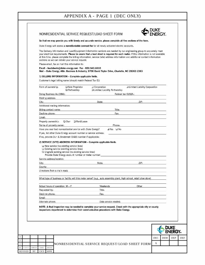
11/20/15
SIMPSON EANES ADCOCK
NONRESIDENTIAL SERVICE REQUEST/LOAD SHEET FORM
0
APPR.CK'DBYREVISED
1
2
3
DEFDEP
X
DEMDEC
APPENDIX A - PAGE 1 (DEC ONLY)
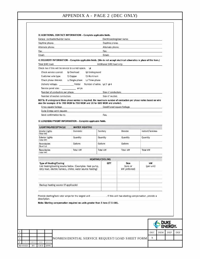
11/20/15
SIMPSON EANES ADCOCK
NONRESIDENTIAL SERVICE REQUEST/LOAD SHEET FORM
0
APPR.CK'DBYREVISED
1
2
3
DEFDEP
X
DEMDEC
APPENDIX A - PAGE 2 (DEC ONLY)

11/20/15
SIMPSON EANES ADCOCK
NONRESIDENTIAL SERVICE REQUEST/LOAD SHEET FORM
0
APPR.CK'DBYREVISED
1
2
3
DEFDEP
X
DEMDEC
APPENDIX A - PAGE 3 (DEC ONLY)
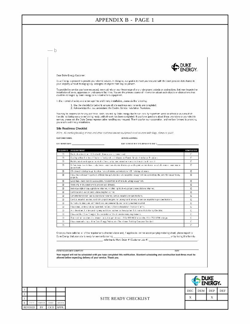
1/6/15
SIMPSON EANES ADCOCK
SITE READY CHECKLIST
0
APPR.CK'DBYREVISED
1
2
3
DEFDEP
X
DEMDEC
APPENDIX B - PAGE 1
X

1/6/15
SIMPSON EANES ADCOCK
ELECTRIC SERVICE INSTALLATION PROVISIONS
0
APPR.CK'DBYREVISED
1
2
3
DEFDEP
X
DEMDEC
APPENDIX B - PAGE 2
X

1/6/15
SIMPSON EANES ADCOCK
CT METERING SITE READINESS CHECKLIST
0
APPR.CK'DBYREVISED
1
2
3
DEFDEP
X
DEMDEC
APPENDIX B - PAGE 3
X
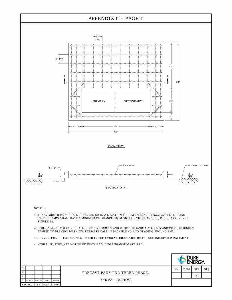
TRUCKS. PADS SHALL HAVE A MINIMUM CLEARANCE FROM OBSTRUCTIONS AND BUILDINGS AS GIVEN IN
PRECAST PADS FOR THREE-PHASE,
75KVA - 300KVA
11/20/15
SIMPSON EANES ADCOCK
PLAN VIEW
SECTION 'A-A'
NOTES:
1. TRANSFORMER PADS SHALL BE INSTALLED IN A LOCATION TO REMAIN READILY ACCESSIBLE FOR LINE
2. SOIL UNDERNEATH PADS SHALL BE FREE OF ROOTS AND OTHER ORGANIC MATERIALS AND BE THOROUGHLY
TAMPED TO PREVENT WASHING. EXERCISE CARE IN BACKFILLING AND GRADING AROUND PAD.
3. SERVICE CONDUIT SHALL BE LOCATED IN THE EXTREME RIGHT SIDE OF THE SECONDARY COMPARTMENT.
4. OTHER UTILITIES ARE NOT TO BE INSTALLED UNDER TRANSFORMER PAD.
0
3
2
1
APPR.REVISED BY CK'D
A
84"
60"12" 12"
7"
20"
41"
68"
TYP.
8"
8" TYP.
A
2-1/2"
3-1/2"
6"
#4 REBAR
FIGURE 52.
FINISHED GRADE
SECONDARYPRIMARY
DEFDEP
X
DEMDEC
APPENDIX C - PAGE 1

TRUCKS. PADS SHALL HAVE A MINIMUM CLEARANCE FROM OBSTRUCTIONS AND BUILDINGS AS GIVEN IN
PRECAST PADS FOR THREE-PHASE,
500KVA - 3750KVA
11/20/15
SIMPSON EANES ADCOCK
PLAN VIEW
SECTION 'A-A'
NOTES:
1. TRANSFORMER PADS SHALL BE INSTALLED IN A LOCATION TO REMAIN READILY ACCESSIBLE FOR LINE
2. SOIL UNDERNEATH PADS SHALL BE FREE OF ROOTS AND OTHER ORGANIC MATERIALS AND BE THOROUGHLY
TAMPED TO PREVENT WASHING. EXERCISE CARE IN BACKFILLING AND GRADING AROUND PAD.
3. SERVICE CONDUIT SHALL BE LOCATED IN THE EXTREME RIGHT SIDE OF THE SECONDARY COMPARTMENT.
4. OTHER UTILITIES ARE NOT TO BE INSTALLED UNDER TRANSFORMER PAD.
0
2
1
APPR.REVISED BY CK'D
A
TYP.
8"
8" TYP.
2-1/2"
3-1/2"
6"
#4 REBAR
FIGURE 52.
12"68"12"
10"
30"
62"
102"
92"
A
FINISHED GRADE
PRIMARY SECONDARY
AND SHALL NOT EXTEND MORE THAN 30" LEFT OF THIS AS INDICATED IN THE ABOVE DRAWING.
30"
ALL SERVICE CONDUITS TO BE
WITHIN THIS 30" WIDE WINDOW.
SEE NOTE 3.
3
DEFDEP
X
DEMDEC
APPENDIX C - PAGE 2

11/20/15
SIMPSON EANES ADCOCK
CUSTOMER/SECONDARY CABLE AND CONDUIT ENTRANCE
SINGLE-PHASE PAD-MOUNTED TRANSFORMER
INSTALLATION (CONCRETE PADS ONLY)
0
APPR.CK'DBYREVISED
NOTES:
1. ALL CONDUITS SHALL STUB-UP A MINIMUM DISTANCE OF ONE INCH (BUT SHALL NOT
EXCEED 2") ABOVE THE TOP OF THE CONCRETE PAD.
1
2
3
25-75 KVA
100 KVA AND LARGER
EDGE OF
PAD-MOUNTED
TRANSFORMER
NO CABLE OR CONDUIT
PERMITTED TO ENTER OR
SECONDARY CABLE
AND CONDUIT AREA
CONCRETE PAD
EDGE OF
PAD-MOUNTED
TRANSFORMER
C
L
OUTSIDE
EXIT IN THIS AREA
EDGE OF CONCRETE
PAD OPENING
GROUND ROD
LOCATION
44"
57"
29"
6"
9"
9"
EDGE OF
PAD-MOUNTED
TRANSFORMER
NO CABLE OR CONDUIT
PERMITTED TO ENTER OR
SECONDARY CABLE AND
CONDUIT AREA
CONCRETE PAD
EDGE OF
PAD-MOUNTED
TRANSFORMER
C
L
OUTSIDE
EXIT IN THIS AREA
EDGE OF CONCRETE
PAD OPENING
28"
45"
10"
6"
42"
9"
GROUND ROD
LOCATION
DEFDEP
X
DEMDEC
APPENDIX C - PAGE 3
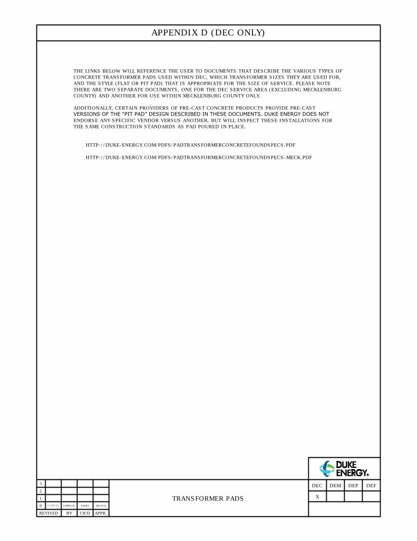
11/20/15
SIMPSON EANES ADCOCK
TRANSFORMER PADS
0
APPR.CK'DBYREVISED
1
2
3
DEFDEP
X
DEMDEC
APPENDIX D (DEC ONLY)
THE LINKS BELOW WILL REFERENCE THE USER TO DOCUMENTS THAT DESCRIBE THE VARIOUS TYPES OF
CONCRETE TRANSFORMER PADS USED WITHIN DEC, WHICH TRANSFORMER SIZES THEY ARE USED FOR,
AND THE STYLE (FLAT OR PIT PAD) THAT IS APPROPRIATE FOR THE SIZE OF SERVICE. PLEASE NOTE
THERE ARE TWO SEPARATE DOCUMENTS, ONE FOR THE DEC SERVICE AREA (EXCLUDING MECKLENBURG
COUNTY) AND ANOTHER FOR USE WITHIN MECKLENBURG COUNTY ONLY.
ADDITIONALLY, CERTAIN PROVIDERS OF PRE-CAST CONCRETE PRODUCTS PROVIDE PRE-CAST
VERSIONS OF THE “PIT PAD” DESIGN DESCRIBED IN THESE DOCUMENTS. DUKE ENERGY DOES NOT
ENDORSE ANY SPECIFIC VENDOR VERSUS ANOTHER, BUT WILL INSPECT THESE INSTALLATIONS FOR
THE SAME CONSTRUCTION STANDARDS AS PAD POURED IN PLACE.
HTTP://DUKE-ENERGY.COM/PDFS/PADTRANSFORMERCONCRETEFOUNDSPECS.PDF
HTTP://DUKE-ENERGY.COM/PDFS/PADTRANSFORMERCONCRETEFOUNDSPECS-MECK.PDF
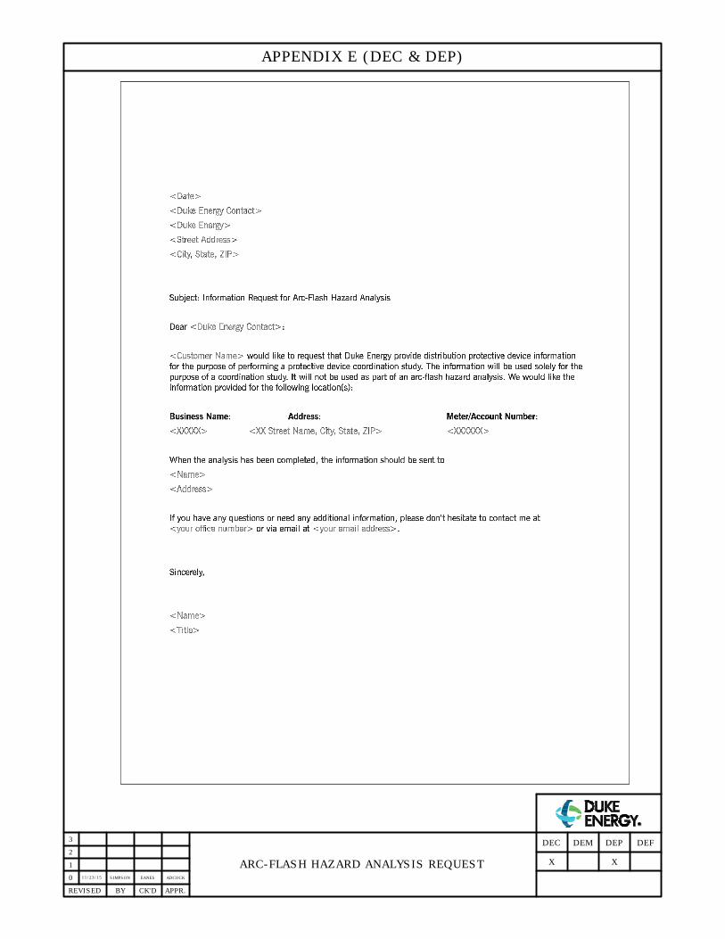
11/23/15
SIMPSON EANES ADCOCK
ARC-FLASH HAZARD ANALYSIS REQUEST
0
APPR.CK'DBYREVISED
1
2
3
DEFDEP
X
DEMDEC
APPENDIX E (DEC & DEP)
X