Embed Size (px)
Citation preview

©G. Kotonya and I. Sommerville 1998 Slide
Methods for requirements engineering

©G. Kotonya and I. Sommerville 1998 Slide
Objectives To explain the role of methods and techniques in
requirements engineering To introduce data-flow modelling To introduce semantic data modelling To introduce object-oriented methods To explain the role of formal methods in requirements
engineering

©G. Kotonya and I. Sommerville 1998 Slide
Role of methods in RE Process of requirements engineering (RE) is usually
guided by a requirements method Requirement methods are systematic ways of
producing system models System models important bridges between the
analysis and the design process

©G. Kotonya and I. Sommerville 1998 Slide
Necessary properties for a RE method Suitability for agreement with the end-user The precision of definition of its notation Assistance with formulating requirements Definition of the world outside Scope for malleability Scope for integrating other approaches Scope for communication Tool support

©G. Kotonya and I. Sommerville 1998 Slide
No ideal RE method There is no ideal requirement method A number of methods use a variety of modelling
techniques to formulate system requirements System models can be enriched by modelling
different aspects of using modelling techniques
©G. Kotonya and I. Sommerville 1998 Slide
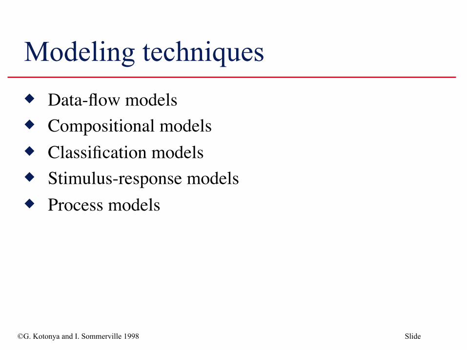
Modeling techniques Data-flow models Compositional models Classification models Stimulus-response models Process models

©G. Kotonya and I. Sommerville 1998 Slide
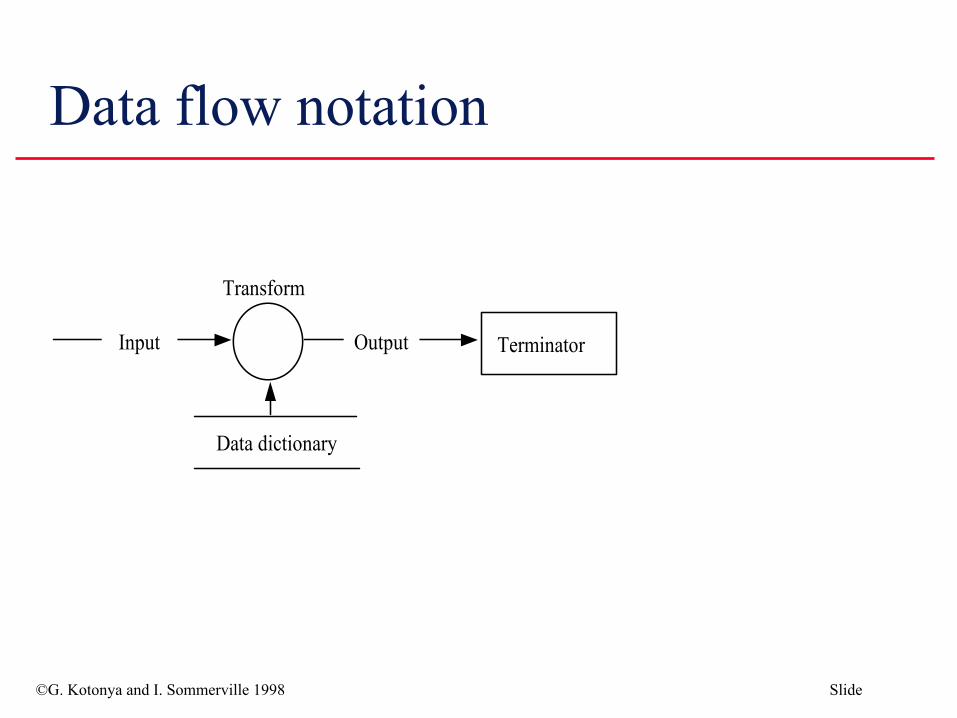
Data flow modelling Based on the notion that systems can be modelled as a
set of interacting functions Uses data-flow diagrams (DFDs) to graphically
represent the external entities, processes, data-flow, and data stores
©G. Kotonya and I. Sommerville 1998 Slide
Data flow notation
©G. Kotonya and I. Sommerville 1998 Slide
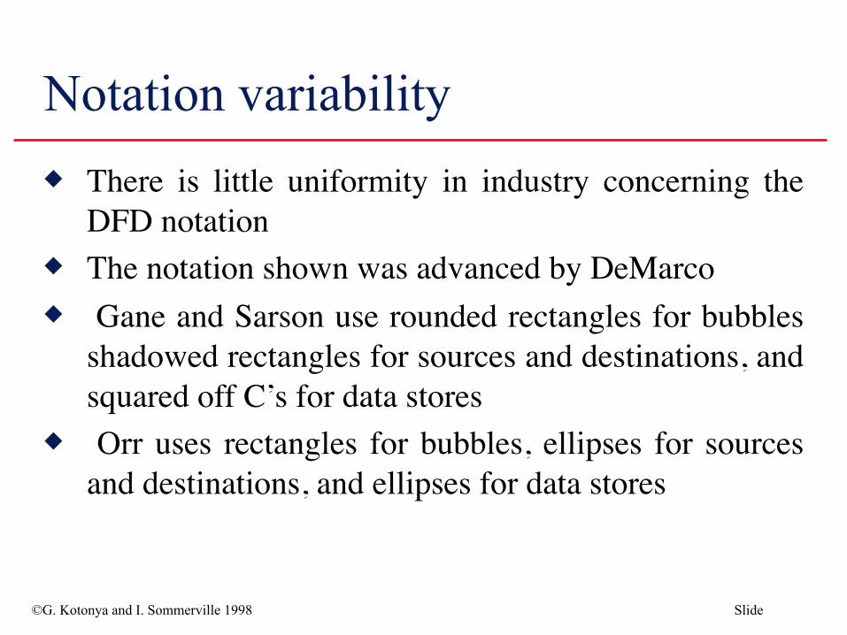
Notation variability There is little uniformity in industry concerning the
DFD notation The notation shown was advanced by DeMarco Gane and Sarson use rounded rectangles for bubbles
shadowed rectangles for sources and destinations, and squared off C’s for data stores
Orr uses rectangles for bubbles, ellipses for sources and destinations, and ellipses for data stores

©G. Kotonya and I. Sommerville 1998 Slide
DFD example Consider a simple library system intended to
automate the issuing of library items The first data-flow diagram derived by the analyst
represents the ‘target’ system at its context level The next level (level 1) of the data-flow diagram is
constructed by decomposing the library system bubble into sub-functions

©G. Kotonya and I. Sommerville 1998 Slide
Library example-Context level data flow diagram

©G. Kotonya and I. Sommerville 1998 Slide
Library example -Level 1 data flow diagram

©G. Kotonya and I. Sommerville 1998 Slide
Structured analysis The data-flow approach is typified by the Structured
Analysis method (SA) Two major strategies dominate structured analysis
• ‘Old’ method popularised by DeMarco • ‘Modern’ approach by Yourdon
©G. Kotonya and I. Sommerville 1998 Slide
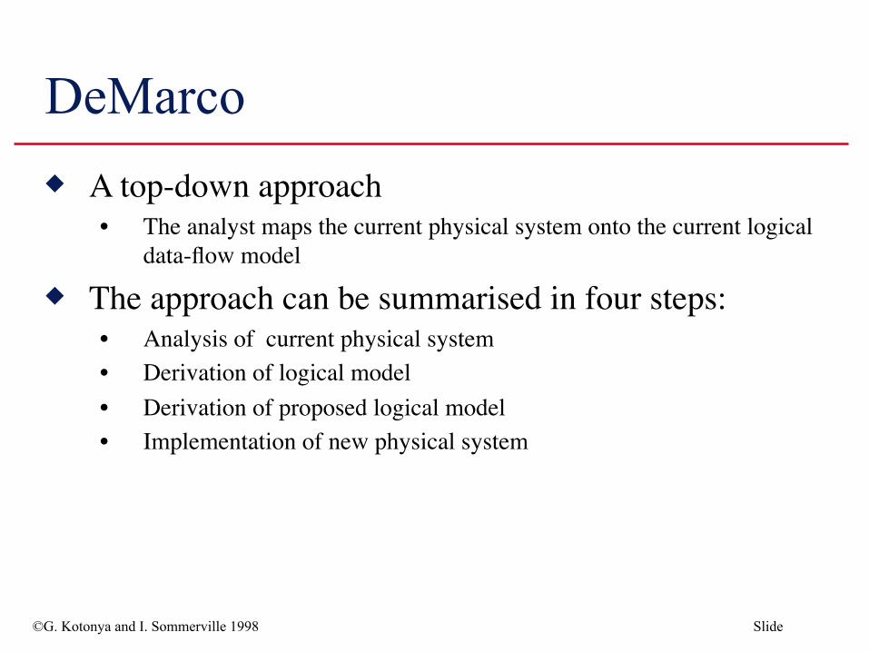
DeMarco A top-down approach
• The analyst maps the current physical system onto the current logical data-flow model
The approach can be summarised in four steps:• Analysis of current physical system• Derivation of logical model• Derivation of proposed logical model• Implementation of new physical system

©G. Kotonya and I. Sommerville 1998 Slide
Modern structured analysis Distinguishes between user’s real needs and those
requirements that represent the external behaviour satisfying those needs
Includes real-time extensions Other structured analysis approaches include:
• Structured Analysis and Design Technique (SADT) • Structured Systems Analysis and Design Methodology (SSADM)

©G. Kotonya and I. Sommerville 1998 Slide
Relational model Data may be modelled using the relational model
• Specifies data as a set of tables, with some columns being used as common keys
Disadvantages of relational model • Implicit data typing• Inadequate modelling of relations
Data model should include information about the semantics of the data

©G. Kotonya and I. Sommerville 1998 Slide
Semantic model Approaches to semantic data modelling include:
• Entity-relationship model (Chen, 1976)• RM/ T (Codd, 1979)• SDM (Hammer and McLeod, 1981)
Models identify the entities in a database, their attributes and their relationships
Uses graphical notations

©G. Kotonya and I. Sommerville 1998 Slide
Notation for semantic data modelling
<Name> <Name>
<Name>
<Input cardinality>
<Output cardinality>
An Entity An Entity
A relation between entities An inheritance relation
©G. Kotonya and I. Sommerville 1998 Slide
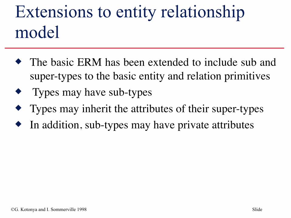
Extensions to entity relationship model The basic ERM has been extended to include sub and
super-types to the basic entity and relation primitives Types may have sub-types Types may inherit the attributes of their super-types In addition, sub-types may have private attributes

©G. Kotonya and I. Sommerville 1998 Slide
ERM example - Software requirement

©G. Kotonya and I. Sommerville 1998 Slide
Object-oriented approaches Closest precursor is entity relationship model Requirements methods based on object orientation:
• Shlaer and Mellor (1988)• Colbert (1989)• Coad and Yourdon (1989)• Wirf-Brock (1990)• Rumbaugh (1991) • Jacobson (1992)• Martin-Odell (1992)
Notations for the various methods are semantically similar

©G. Kotonya and I. Sommerville 1998 Slide
Object Are major actors, agents, and servers in the problem
space of the system Identified by analysing the domain Objects include:
• Devices that the system interacts with• Systems that interface with the system under study• Organisational units• Things that must be remembered over time • Physical locations or sites• Specific roles played by humans

©G. Kotonya and I. Sommerville 1998 Slide
Basic concepts Encapsulation Class Inheritance Operations or Services

©G. Kotonya and I. Sommerville 1998 Slide
Object definition Something real or abstract about which we store data
and those operations that manipulate the data Examples include:
An account, a sensor, a software design, a car , an organisation
May be composite - composed of other objects

©G. Kotonya and I. Sommerville 1998 Slide
Class definition An implementation of an object type
• The object type Bank Customer refers to a class of bank customers
Objects that share common attributes and operations• An object is an instance of a class• For example, if “John Smith” is a bank customer, then bank customer
is the class and “John Smith” is an instance of the bank customer

©G. Kotonya and I. Sommerville 1998 Slide
Operations and methods Used to read and manipulate the data of an object Reference only the data structures of that object type To access the data structures of another object, objects
must send messages to that object Methods specify the way in which operations are
encoded in software

©G. Kotonya and I. Sommerville 1998 Slide
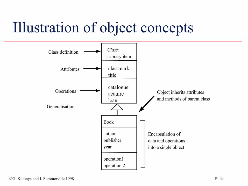
Encapsulation Packaging together of data and operations that
manipulate the data Details of how the operation is performed hidden
from user Prevents the unauthorised access of an object’s data

©G. Kotonya and I. Sommerville 1998 Slide
Inheritance Objects at a lower level in class hierarchy inherit the
operations and attributes of their parent(s) Objects are able to incorporate data and/or operations
specific to themselves Inherits data from more than one parent is called
multiple inheritance.
©G. Kotonya and I. Sommerville 1998 Slide
Illustration of object concepts

©G. Kotonya and I. Sommerville 1998 Slide
Messages Objects communicate by sending messages Message comprises:
• Name of receiver object• Operation to be invoked• Optional set of parameters
When an object receives a message it causes an operation to be invoked
The operation performs the appropriate method

©G. Kotonya and I. Sommerville 1998 Slide
Message passing

©G. Kotonya and I. Sommerville 1998 Slide
Object modelling - Library example A library system is intended to provide its users with the ability
to automate the process of:• Acquiring library items• Cataloguing library items• Browsing library items• Loaning library items
Library items comprise published and recorded material The system will be administered by a member of the library
staff Users must register with the system administrator before they
can borrow library items

©G. Kotonya and I. Sommerville 1998 Slide
Library example (contd.) Library users are drawn from three primary groups:
Students, Members of staff and External users
All library users have as part of their registration: Name, Library number, Address, Account
In addition the following information also required for registration:Students - Degree programme and admission number. Staff - Staff number External users - Employer details

©G. Kotonya and I. Sommerville 1998 Slide
Steps in object-oriented method Most methods based on the object-oriented model
share certain common analysis steps:• Identify core objects• Construct the object structures defining the associations between
object classes• Define the attributes associated with each object• Determine the relevant operations for each object• Define the messages that may be passed between objects

©G. Kotonya and I. Sommerville 1998 Slide
Object-oriented notation used

©G. Kotonya and I. Sommerville 1998 Slide
Step 1 - Initial classes identified

©G. Kotonya and I. Sommerville 1998 Slide
Step 2 - Relationships between classes We can identify the following relationships from the
partial requirements:(i) A library user borrows a library item(ii) A library item is recorded or published(iii) The system administrator registers the library user(iv) Library users are students, staff and external users(v) The system administrator catalogues the library items(vi) The library assistant issues the library items

©G. Kotonya and I. Sommerville 1998 Slide
Step 2 - Basic object model showing attributes and relationships

©G. Kotonya and I. Sommerville 1998 Slide
Step 2 - Inheritance for Library user

©G. Kotonya and I. Sommerville 1998 Slide
Step 2 - Inheritance for library item

©G. Kotonya and I. Sommerville 1998 Slide
Step 3 - Identifying the attributes Attributes can be revealed by the analysis of the system
requirements For example, it is a requirement that all library users must be
registered before they can use the library• This means that we need to keep registration data about library users• Library users may also be provided with an account to keep track of
the items loaned to them Library item has the attributes; title, description and classmark The library user class has the attributes; name, address and
library id
©G. Kotonya and I. Sommerville 1998 Slide
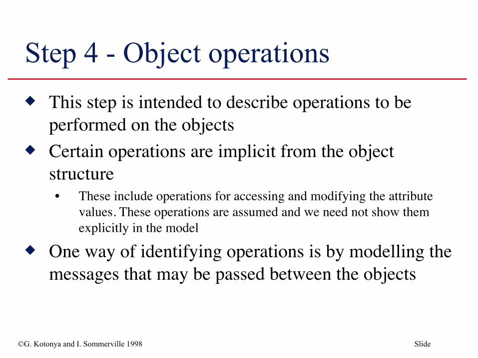
Step 4 - Object operations This step is intended to describe operations to be
performed on the objects Certain operations are implicit from the object
structure• These include operations for accessing and modifying the attribute
values. These operations are assumed and we need not show them explicitly in the model
One way of identifying operations is by modelling the messages that may be passed between the objects
©G. Kotonya and I. Sommerville 1998 Slide
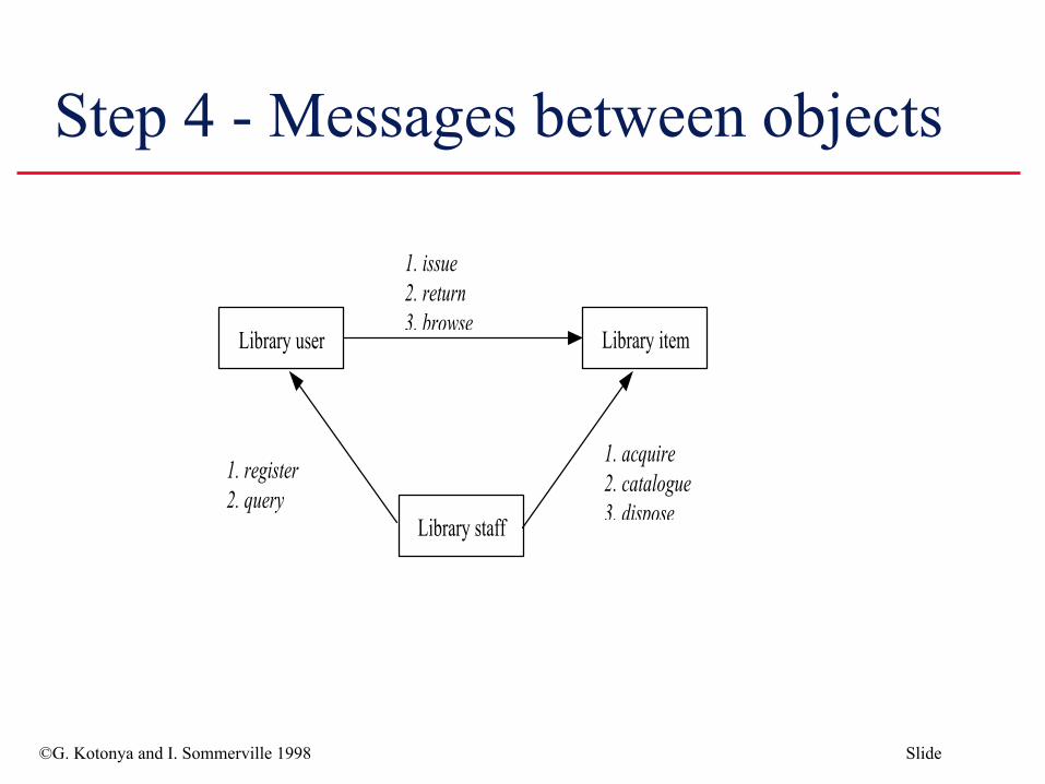
Step 4 - Messages between objects
©G. Kotonya and I. Sommerville 1998 Slide
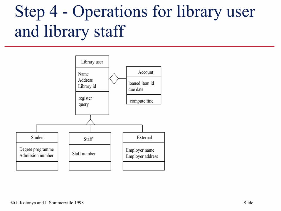
Step 4 - Operations for library user and library staff

©G. Kotonya and I. Sommerville 1998 Slide
Step 4 - Operations for library item
©G. Kotonya and I. Sommerville 1998 Slide
Use case and event scenarios Object operations may also be identified by modelling
event scenarios for the different functions provided by the system• Events are then traced to objects that react to them
Typically scenarios model the interactions between the users and the system

©G. Kotonya and I. Sommerville 1998 Slide
Typical use-case scenario for library system

©G. Kotonya and I. Sommerville 1998 Slide
Event scenario for borrowing item

©G. Kotonya and I. Sommerville 1998 Slide
Formal methods Requirements specification techniques can be
categorised on a “formality” spectrum Semi-formal and informal methods
• Use natural language, diagrams, tables and simple notation • Include structured analysis and object-oriented analysis
Formal methods include:• Based on mathematically formal syntax and semantics• Include Z, B, VDM, LOTOS

©G. Kotonya and I. Sommerville 1998 Slide
Formal methods (contd.) Provide a means for achieving a high degree of
confidence that a system will conform to its specification
Do not absolute guarantee of correctness Have little directly to offer to the problems of
managing software projects• However, benefits can be gained from gaining a clear understanding
of the task at an early stage

©G. Kotonya and I. Sommerville 1998 Slide
Components of formal specification language Syntax that defines the specific notation with which
the specification is represented Semantics that help to define a “universe of objects”
that will be used to describe the system Relations which define the rules that indicate which
objects properly satisfy the specification
©G. Kotonya and I. Sommerville 1998 Slide
Formal methods not widespread Formal methods are not widely used amongst
software developers Factors contributing to slow acceptance of formal
methods:• Difficulty in understanding the notations• Difficulty in formalising certain aspects of requirements• Payoff is not obvious.

©G. Kotonya and I. Sommerville 1998 Slide
Formal specification languages The number of formal specification languages in use
today can be broadly divided into two categories. Model-based notations
Z and Vienna Development Method (VDM)
Process algebras -based notationsCommunicating Sequential Processes (CSP), CCS and LOTOS
©G. Kotonya and I. Sommerville 1998 Slide
Advantages of formal methods Removes ambiguity Encourages greater rigor in the early stages of
software engineering Possible to verify the correctness, incompleteness and
inconsistency checking of the specification
©G. Kotonya and I. Sommerville 1998 Slide
Disadvantages of formal methods Difficult to represent behavioural aspects of problem Some requirements can only be determined through
empirical evaluation and prototyping Do not address the problem of how the requirements
are constructed Lack of adequate tool support

©G. Kotonya and I. Sommerville 1998 Slide
Z - A model based formal method A Z specification is presented as a collection of
schemas A Schema comprises three main parts:
Name, Declarations and Predicates
Schema declarations set out the names and types of entities introduced in the schema
Schema predicate sets out the relationships between the entities in the declaration
©G. Kotonya and I. Sommerville 1998 Slide
Using Z Variable declarations are of the form identifier:type Predicates give properties of, and relationships between the
variables A schema may be used to describe either a state or an
operation• To describe a state, the declared variables form the components of
the state and the predicates give the invariant properties of the state• For an operation, the declarations consist of the initial state
components, the final components, the inputs and the outputs of the operation
• For an operation, the predicate part describes the relation between the inputs, outputs, and initial and final states

©G. Kotonya and I. Sommerville 1998 Slide
Z Schema

©G. Kotonya and I. Sommerville 1998 Slide
Library example The state space of the lending library can be defined
using the following schema:

©G. Kotonya and I. Sommerville 1998 Slide
Schema for borrow operation
©G. Kotonya and I. Sommerville 1998 Slide
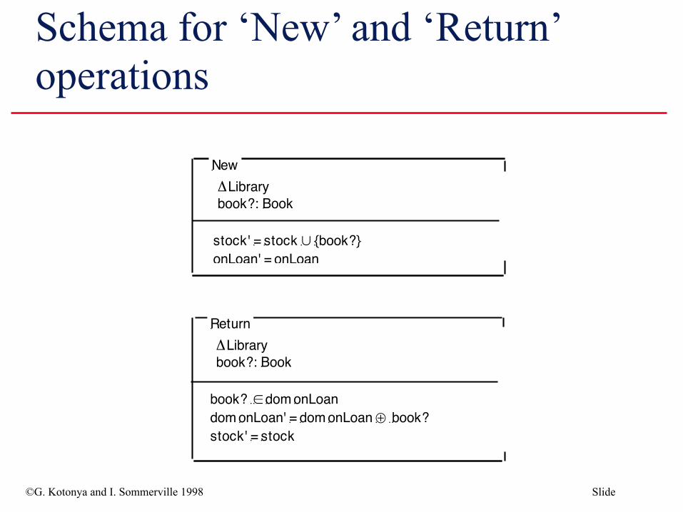
Schema for ‘New’ and ‘Return’ operations

©G. Kotonya and I. Sommerville 1998 Slide
Key points No ideal requirements method System models can be considerably enriched by combining
different techniques Data-flow model is based on the notion that systems can be
modelled as a set of interacting functions The object-oriented approach is based on the notion that
systems can be modelled as a set of interacting objects Formal methods are based on mathematical principles and are
intended to achieve a high degree of confidence that a system will conform to its specifications