Embed Size (px)
Citation preview

STATE OF CALIFORNIA
DEPARTMENT OF TRANSPORTATION __________________________________________________________
REQUEST FOR PROPOSALS
FOR DESIGN AND CONSTRUCTION ON STATE HIGHWAY IN
MADERA COUNTY, IN AND NEAR MADERA FROM 0.3 MILE SOUTH
OF SOUTH MADERA OVERCROSSING TO 0.4 MILE
NORTH OF AVENUE 16 OVERCROSSING
DISTRICT 06, ROUTE 99
__________________________________________________________
CONTRACT NO. 06-0E0404
06-Mad-99-9.5/13.1
Project ID 0600000043
Federal Aid Project
NH-P099(538)N
Addendum No. 2 Issued April 11, 2011

April 11, 2011 2 Addendum No. 2 CONTRACT NO. 06-0E0404
The Department issues this Addendum No. 2 to inform Proposers of the following changes and corrections to the RFP. INSTRUCTIONS TO PROPOSERS
The Instructions to Proposers is modified as indicated by the deletions and additions set forth below.
Appendix D
Appendix D, Price Proposal Submittal Requirements, is modified as indicated below.
1 General Instructions
The total price offered by Proposer for its Proposal for all Work is referred to herein as the “Proposal Price” and is indicated on Line 26 29 of Form 9 (Proposal Price). Payments to Design-Builder under the Contract will be made based on the Proposal Price in accordance with Book 1, Section 11.
2 Content
The Price Proposal shall be organized to correspond to the items listed in this Section 2. Proposer is encouraged to use tabbed dividers to separate the contents of the Price Proposal.
A. Proposal Price
Provide a hardcopy and electronic copy of Form 9 (Proposal Price).
Provide at Line 30 of the Price Proposal the unit price for concrete panel replacement to be used in accordance with Book 1, Section 11.1.5.
The lump sum price for concrete panel replacement shall be determined by multiplying the unit price set forth in Line 30 and the quantity amount set forth in Book 2, Section 1.3.3 for concrete panel replacement. In the event of a discrepancy, Department shall be entitled to perform the calculation using the unit price from Line 30 and the quantity amount set forth in Book 2, Section 1.3.3 for concrete panel replacement in determining the Proposal Price.
Form 9 Proposal Price
Form 9 is deleted and replaced with the revised Form 9 Proposal Price at the end of this Addendum.
BOOK 1 DESIGN-BUILD CONTRACT
The Book 1, Design-Build Contract, is modified as indicated by the deletions and additions set forth below.
11.1.4 Asphalt Price Fluctuations
April 11, 2011 3 Addendum No. 2 CONTRACT NO. 06-0E0404
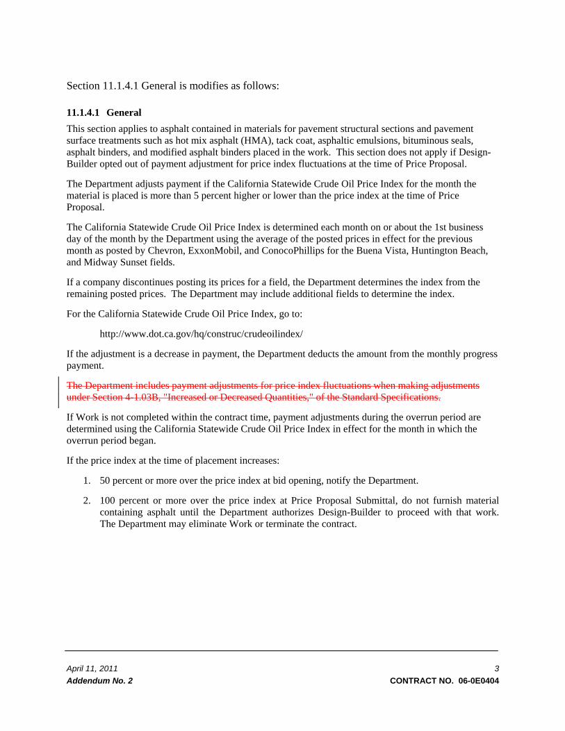
Section 11.1.4.1 General is modifies as follows: 11.1.4.1 General This section applies to asphalt contained in materials for pavement structural sections and pavement surface treatments such as hot mix asphalt (HMA), tack coat, asphaltic emulsions, bituminous seals, asphalt binders, and modified asphalt binders placed in the work. This section does not apply if Design-Builder opted out of payment adjustment for price index fluctuations at the time of Price Proposal.
The Department adjusts payment if the California Statewide Crude Oil Price Index for the month the material is placed is more than 5 percent higher or lower than the price index at the time of Price Proposal.
The California Statewide Crude Oil Price Index is determined each month on or about the 1st business day of the month by the Department using the average of the posted prices in effect for the previous month as posted by Chevron, ExxonMobil, and ConocoPhillips for the Buena Vista, Huntington Beach, and Midway Sunset fields.
If a company discontinues posting its prices for a field, the Department determines the index from the remaining posted prices. The Department may include additional fields to determine the index.
For the California Statewide Crude Oil Price Index, go to:
http://www.dot.ca.gov/hq/construc/crudeoilindex/
If the adjustment is a decrease in payment, the Department deducts the amount from the monthly progress payment.
The Department includes payment adjustments for price index fluctuations when making adjustments under Section 4-1.03B, "Increased or Decreased Quantities," of the Standard Specifications.
If Work is not completed within the contract time, payment adjustments during the overrun period are determined using the California Statewide Crude Oil Price Index in effect for the month in which the overrun period began.
If the price index at the time of placement increases:
1. 50 percent or more over the price index at bid opening, notify the Department.
2. 100 percent or more over the price index at Price Proposal Submittal, do not furnish material containing asphalt until the Department authorizes Design-Builder to proceed with that work. The Department may eliminate Work or terminate the contract.

April 11, 2011 4 Addendum No. 2 CONTRACT NO. 06-0E0404
Add Section 11.1.4.4 as follows: 11.1.4.4 Allowance for Asphalt Price Index Fluctuations The Contract Price includes an allowance of $610,000 for asphalt price index fluctuations (“Asphalt Price Index Fluctuation Allowance”).
A monthly price adjustment will be made as specified in Section 11.1.4.3 and Exhibit H to account for significant fluctuations in the cost of asphalt over the course of the Project. The adjustment amount shall be calculated as specified in Section 11.1.4.3.
The monthly price adjustment shall be tracked throughout the Project and charged against the Asphalt Price Index Fluctuation Allowance. Any upward adjustment resulting in a payment to the Design-Builder shall be contained in the progress payment and shall be deducted from the Asphalt Price Index Fluctuation Allowance. Any downward adjustment resulting in a credit to the Department shall be added to the Asphalt Price Index Fluctuation Allowance.
If at the end of the Project any portion of the Asphalt Price Index Fluctuation Allowance remains unused, including any additions based on credits to the Department, Department shall issue a change order decreasing the Contract Price by the remaining amount of the Asphalt Price Index Fluctuation Allowance.
Add Section 11.1.5 Unit Price for Certain Concrete Panel Replacement as follows:
11.1.5 Unit Price for Certain Concrete Panel Replacement The Contract Price includes an allowance (“Panel Replacement Allowance”) of $70,000 for the replacement of panels in excess of the amount set forth in Book 2, Section 1.3.3.
In the event the actual quantity of panel replacements exceed the amount set forth in Book 2, Section 1.3.3, Design-Builder shall be entitled to compensation for the extra quantity of panels replaced. Payment to Design-Builder for such Work will be made on the basis of the unit price for panel replacement shown in the Price Proposal Line 30 and the actual excess quantities as measured in accordance with Book 2, Section 1.3.3. Payment to Design-Builder will be made only for the actual excess quantities, and shall be subject to the limitations on increases to the Contract Price set forth in Section 13.5.1. Payment shall initially be made from the Concrete Panel Replacement Allowance. If the compensation for the actual excess quantities as measured in accordance with Book 2, Section 1.3.3 exceeds the Concrete Panel Replacement Allowance, Design-Builder shall be entitled to a Unit Price Change Order under Section 13.6.2 for the costs in excess of the Concrete Panel Replacement Allowance and the amount of such Change Order shall be based solely on the unit price for panel replacement shown in the Price Proposal Line 30.
In the event the actual quantity of panel replacements being replaced is less than the amount set forth in Book 2, Section 1.3.3, Department shall be entitled to a Change Order reducing the Contract Price for the underrun. The reduction will be made on the basis of the unit prices for panel replacement shown in the Price Proposal Line 30 and the actual underrun quantities as measured in accordance with Book 2, Section 1.3.3. The reduction shall be made from progress payments and/or final payment, as deemed appropriate by Department.
If at the end of the Project any portion of the Concrete Panel Replacement Allowance remains unused, Department shall issue a Change Order decreasing the Contract Price by the remaining amount of the Concrete Panel Replacement Allowance.

April 11, 2011 5 Addendum No. 2 CONTRACT NO. 06-0E0404
In all cases, Design-Builder shall keep detailed records of the quantities panel replacement, and shall submit supporting documentation of such quantities with its invoices.
In all cases, Design-Builder shall keep detailed records of the quantities panel replacement, and shall submit supporting documentation of such quantities with its invoices.
Section 11.5 Deductions is modified as indicated below:
11.5 Deductions Department may deduct from any amounts otherwise owing to Design-Builder, including each progress payment and the final payment, the following:
(a) any anticipated or accrued losses, liability, Liquidated Damages or other damages for which Design-Builder is responsible hereunder;
(b) the estimated cost of remedying any Nonconforming Work or otherwise remedying any breach of contract by Design-Builder;
(c) any amounts that Department deems advisable, in its sole discretion, to cover any existing or threatened claims, Liens and stop notices by Subcontractors, Suppliers, laborers, Utility Owners or other third parties relating to the Project;
(d) any sums expended by Department in performing any of Design-Builder’s obligations under the Contract which Design-Builder has failed to perform; and
(e) any other sums which Department is entitled to deduct from the Contract Price or to recover from Design-Builder under the terms of the Contract.
Department’s failure to deduct from a progress payment any amount which Department is entitled to recover from Design-Builder under the Contract shall not constitute a waiver of Department’s right to such amounts.
Exhibit A, Definitions Add the following definitions as provided below:
Asphalt Price Index Fluctuation Allowance
The meaning set forth in Section 11.1.4.
Panel Replacement Allowance
The meaning set forth in Section 11.1.5.
Exhibit E Disadvantaged Business Enterprise (DBE) Special Provisions for Design-Build Projects Section E of Exhibit E is modified as indicated by the deletions and additions set forth below: E. SUBMITTAL OF DOCUMENTATION

April 11, 2011 6 Addendum No. 2 CONTRACT NO. 06-0E0404
With the submission of the initial Proposal and for all subcontracts subsequently awarded where goals are set, regardless of contract size, the Design-Builder, Subcontractor, Consultant, Subconsultant, Supplier and Service Provider will be required to: (a) propose the participation of specific UDBEs to meet the goal; or (b) demonstrate good faith efforts to meet the goal. A Design-Builder, Subcontractor, Consultant, Subconsultant, Supplier and Service Provider must provide justification if it rejects bids, quotes, or proposals from properly certified, qualified UDBE firms.
In order to fulfill a UDBE goal, the firms utilized as UDBE Subcontractors, Consultants, Subconsultants, Suppliers or Service Providers must be certified as DBEs by the California Unified Certification Program prior to the release of the RFP, and/or subsequent to the award of the Contract, the advertisement of bids or the selection of any new Subcontractors, Consultants, Subconsultants, Suppliers or Service Providers during the project. For a list of DBEs certified by the California Unified Certification Program, go to:
http://www.dot.ca.gov/hq/bep/find_certified.htm
The Design-Builder must submit the following documents to the Department. These documents must be submitted with the initial Proposal.
1. Design-Builder's Good Faith Efforts Documentation
2. Design-Build Bidders List
3. Supporting Documentation to Verify Good Faith Efforts - Including, but not limited to a copy of the signed agreements with each UDBE to be utilized by the Design-Builder, Contractor, Subcontractor, Consultant, Subconsultant, Supplier or Service Provider.
4. OJT Training Acknowledgement Form
5. UDBE Goal Certification Form (Form 17).
The completed Design-Build Bidders List should include information on: (1) all DBE and non-DBE firms that submitted a bid/proposal for the project; (2) the proposed firms to be used on the project as contractors/subcontractors/ consultants/Subconsultants/suppliers/service providers; (3) a description of the work; (4) bid dollar amount; (5) years the company has been in business; and (6) the firm's average annual gross receipts for the past three years. The Design-Builder must submit a Design-Build Bidder's List regardless of whether or not it has indicated sufficient UDBE participation to meet the UDBE goal.
The Design-Builder must also submit additional information, which supports its Good Faith Efforts such as those typical Good Faith Efforts listed in DBE Special Provisions for Design-Build Projects as well as summaries of the contractor's discussions and/or solicitation efforts of DBE firms (along with the firm names, addresses and contact persons). This information can include but is not limited to copies of solicitation letters and/or faxes to UDBE firms.
The Design Builder's Subcontractors, Consultants, Subconsultants, Suppliers and Services Providers, including DBE and non-DBE firms, that subcontract part of their work or purchase supplies from other firms are also required to demonstrate that they made Good Faith Efforts to provide opportunities for UDBE firms to participate on this Design-Build project.

April 11, 2011 7 Addendum No. 2 CONTRACT NO. 06-0E0404
Section R of Exhibit E is modified as indicated by the deletions and additions set forth below: R. REPORTING
(a) DBE RECORDS - The Design-Builder shall maintain records and shall require its Subcontractors/Consultants/Subconsultants/Suppliers/Service Providers that are utilizing DBE (including UDBE) firms in such contracts to maintain records to verify DBE participation as set forth in the Proposal and as modified during the course of the Contract. Such records shall show name and business address of each DBE participating in the Contract, Subcontract and Consultant/Subconsultant or Supply/Service Provider Agreement and the total dollar amount actually paid to each UDBE and the date of payment.
(b) REPORTING REQUIREMENTS AND DEPARTMENT REVIEW - The Design-Builder will submit ongoing progress reports to Department on its payments to all its Contractors/Subcontractors/Suppliers/Service Providers, regardless of their tier or UDBE status, within ten (10) days after receiving payment from Department until final payment is made. The Design-Builder shall submit these progress reports on its payments to Contractors/Subcontractors/Consultants/Subconsultants/Suppliers/Service Providers on the attached Contractor Payment Form. The Design-Builder shall submit a copy of each Contractor Payment Reports to the Department.
A Summary of Contracts, Subcontracts, Consultant/Subconsultant and Supply/Service Provider Agreements Awarded shall be submitted to Department on a monthly basis, which should include the firm name, address, phone number, contact person, amount of the contract, subcontract, consultant/Subconsultant or supply/service provider agreement, description of work and length of the contract, subcontract, consultant/ Subconsultant or supply/service provider agreement.
Department will review the Summary of Contracts, Subcontracts, Consultant/Subconsultant and Supply/Service Provider Agreements Awarded Monthly Progress Report to monitor and determine whether the utilization of UDBE firms is consistent with the commitment of the Design-Builder, as stated in its Proposal.
If it is determined that the Design-Builder's UDBE utilization during performance of the Contract is not consistent with the commitment thereto, the Design-Builder will be requested, in writing, to submit evidence of its good faith efforts to meet the goal. The Design-Builder shall be given ten (10) working days to submit this documentation. Failure to respond shall place the Design-Builder in Non-Compliance, subject to sanctions as provided in this contract herein.
(c) SUMMARY OF SUBCONTRACTS AWARDED AND PAID REPORT - As indicated above in the sections on "Reporting Requirements and Department Review" and "Prompt Payment," the Design-Builder is required to submit: (a) a Summary of Subcontracts Awarded on a monthly basis; by no later ten (10) days after receiving payment from Department.
Department reserves the right to withhold progress payment until the required reports have been furnished.
(d) QUARTERLY REVIEW/UDBE WORK AND PAYMENT SCHEDULE - A review of the Design-Builder’s compliance with the UDBE participation goal will be conducted on a quarterly basis as follows:

April 11, 2011 8 Addendum No. 2 CONTRACT NO. 06-0E0404
Not later than thirty (30) days following the Notice to Proceed 1, the Design-Builder shall submit a “UDBE Work and Payment Schedule” to the Department, which shall indicate for the entire Contract period a listing on a per month basis, of the UDBE firms which the Design-Builder expects to utilize, the amount of payments expected to be made to UDBEs, and the percentage of each UDBE firm’s contract that will be completed on each month. The “UDBE Work and Payment Schedule” shall be updated every sixty (60) days consistent with the updates to the Baseline Schedule.
During the sixty (60) days following Design-Builder’s submittal of the “UDBE Work and Payment Schedule”, Department will review the Contractor Payment Reports to determine if the Design-Builder is meeting the “UDBE Work and Payment Schedule”. If the Design-Builder has not met the “UDBE Work and Payment Schedule,” Department will notify the Design-Builder of the need for correction of UDBE participation levels to meet the “UDBE Work and Payment Schedule” by the next quarter.
Sixty days (60) following such notice, Department will evaluate whether the Design-Builder has corrected UDBE participation deficiencies to meet the “UDBE Work and Payment Schedule”. If such deficiencies are not corrected and the level of UDBE participation remains below that provided in the “UDBE Work and Payment Schedule”, and the Design-Builder is unable to show it made good faith efforts to do so, Department may impose liquidated damages in accordance with the Contract herein.
(e) DBE FINAL REPORT - A DBE Final Report shall be submitted with the Request for Final Payment. The DBE Final Report shall consist of:
(1) A Report listing all Contractors, Subcontractors, Consultants, Subconsultants, Suppliers and Service Providers and DBE (including UDBE) activity (work performed) on the Design-Build Contract; and
(2) A Summary of Good Faith Efforts, covering the entire Design-Build Contract period if the UDBE goal has not been met for the Contract.
The Department shall evaluate the Contractor's Final Report and make a determination as to whether the Contractor made Good Faith Efforts to meet the UDBE goal. The Department shall issue a Final Report with its determination on the Contractor's Good Faith Efforts no later than 60 days following the Contractor's submission of its Final Report.
BOOK 2 PROJECT REQUIREMENTS
The Book 2, Project Requirements, is modified as indicated by the deletions and additions set forth below.
Section 1.3.3. is modified as indicated below:

April 11, 2011 9 Addendum No. 2 CONTRACT NO. 06-0E0404
1.3.3 General Description
The Design-Builder shall not rely on the physical description contained in this Section 1 to identify all Project components. The Design-Builder shall determine the full scope of the Project through thorough examination of the RFP and the Project Site, or as may be reasonably inferred from such examination.
• The Project is to replace with full depth hot mix asphalt the failed existing concrete panels as determined by the Department in its sole discretionwith hot mix asphalt. The locations limits of concrete panel replacement are from post Post mile Mile 9.5 to Post-Mile 10.0 and from Post Mile 11.7 to Post Mile 13.1. A typical panel dimension is 12 ft x 15 ft. The preliminary quantities and locations are shown in reference drawing Q-1. Design-Builder need toshall coordinate with the Department for final locations of panels to be replaced. Department in-charge to contact Department maintenance pavement management personnel to finalize locations. The quantity of concrete panel replacement to be paid for will be measured by the cubic yard. Department estimates that 1800 cubic yards of concrete panel replacement will be required. The volume to be paid for will be calculated on the basis of the dimensions identified during a field review in coordination with the Department. Concrete panel replacement shall consist of removing existing portland cement concrete pavement and underlying cement treated base and replacing with full depth hot mix asphalt in conformance with Section 39 “Hot Mix Asphalt” of the Standard Specifications.
• From post mile 10.0 to 11.6, replace remove the existing Portland cement concrete (PCC) pavement and a 0.35’ asphalt concrete overlay on top in lane No. 2 with. Construct a 14’ wide continuous re-enforced reinforced concrete pavement (CRCP). Remove the 10’ existing outside shoulder and replace with 8’wide hot mix asphalt concrete shoulder.
For Hot Mix Asphalt/CRCP transition use Concrete/Hot Mix Asphalt transition panel as shown on the Caltrans Revised Standard Plan P30, a terminal joint per Caltrans New Standard Plans P31A/B, and then one of the following combinations:
a. wide flange beam and expansion joint per Caltrans New Standard Plan P32A/B, or
b. expansion joint and 2 pavement anchors per Caltrans New Standard Plans P31A/B.
If expansion joints are placed within the CRCP, 2 pavement anchors on each side are required.
• From post mile 10.0 to post mile 11.6. Rebuild the median with a 12’ Jointed Plain Concrete Pavement (JPCP) from edge of travel way with 2% slope towards away from the concrete barrier. Replace lane no.1 with Jointed Plain Concrete Pavement (JPCP). All concrete lanes shall be design supported.
For bridges and joining to jointed plain concrete pavement, place terminal joint per Caltrans Standard Plans P31A/B followed by one of the following combinations:
a. wide flange beam and expansion joint per Caltrans New Standard Plans P32A/B
b. expansion joint and 2 pavement anchors per Caltrans New Standard Plans P31A/B
• No work on the deck of Fresno River Bridge (PM 11.6 to 11.7).
The Project will include:
Cold Plane 0.35 thick of Asphalt Concrete pavement from PM. 9.5 to 10.0 and PM. 11.7 to 13.1. As determined by the Department in its sole discretion, repair any localized areas such as rutting greater than 0.05’ and/or loose or spalling pavement and pumping cracks in the PCC with HMA and, if

April 11, 2011 10 Addendum No. 2 CONTRACT NO. 06-0E0404
necessary, aggregate base also. Seal any remaining cracks wider than 0.02’. Then Ooverlay with 0.1’dense grade 0.1’ hot mix asphalt (type A) as a leveling course, pPlace SAMI-R (stress absorbing membrane interlayer, rubberized) and overlay with 0.5 ft. dense graded hot mix asphalt (type A).
Construct rumble strips on the inside and outside AC shoulders between Post mile 9.5 to 10.0 aAnd Post mile 11.7 to 13.1
Upgrade all existing guard rail to current standards within the project limits. Construct a new metal beam guard rail to shield the existing census control box on the right side of Route
99 Location: North of southbound off-ramp to Route 145.
Modify lighting and sign illumination at the following approximate locations (PM 9.52, 10.03 to 10.2, 10.5 to 10.5, 10.8 to 11.0, 11.2 to 11.3, 11.9 to 12.0, 12.3 to 12.3, 12.6 to 12.7, and 13.0 and to 13.1.
Modify Traffic Monitoring Station at the following approximate locations PM (9.8, 10.2, 10.6, 11.2, 11.6, 12.1 to 12.2, 12.5, and 12.8)
Closed circuit Television System at these approximate locations (PM 9.8,10.8,) Changeable Message Sign System (CMS). Model 500 CMS with led LED sign. Design foundation and
post will be determined by Design Builder. (PM 10.5) Modify Roadside Weather Information system. Replace the existing sensor and install a new sensor with
a surface probe Add count loops to all On and Off Ramps and tie into existing Traffic monitoring system. Add piezo’s on the existing count loops on Route 99 mainline both Northbound and Southbound Ensure to upgrade all traffic signs within the project limits are to current standards. Install a drainage system under the Avenue. 16 Bridge on the northbound side by the shoulder to drain to
the outside of the roadway. • Replace all Type A dike with Type A dike in cut areas and with Type E dike in non-cut areas. Place temporary and permanent striping and signing Maintain two 12’ lanes open during construction in both direction Night time closure to one lane permitted per lane closure chart Maintain existing roadway profile and vertical clearance under the bridges Need to have a 1’0 shoulder on each side of temporary detour lane. Within the project Location there are three pump house with a storage box under the Freeway:
Cleveland Ave. Pump house Post Mile 12.1 Route 99/145 Pump house Post Mile 10.3 Madera 99 undercrossing pump house Post Mile 11.1
The alternate Department approved crash cushions to be considered to shield the south end of the concrete barriers at gore area are TL3 Non gating System: TAU II, Smart Cushion, or QuadGuard.
Section 2.2.2.3 is modified as indicated below: 2.2.2.3 Progress Report
The Design-Builder shall include the following in a monthly progress report:
1. Summary of work performed during the previous month. Include digital color photographs of the Project progress.

April 11, 2011 11 Addendum No. 2 CONTRACT NO. 06-0E0404
2. Safety Summary of Project accidents (frequency and severity) and corrective actions taken Updates to emergency services access points to the Project Site Updates on safety training provided
3. Labor compliance The total monthly labor hours for construction/maintenance and non-construction personnel by
classification of management, engineering, and other technical personnel used on the job. Disadvantaged Business Enterprise (DBE) and Underutilized Disadvantaged Business Enterprise
(UDBE) progress and Project updates Equal Employment Opportunity (EEO) progress and Project updates Update on labor compliance unresolved issues
4. Quality updates • Summary of quality audits and quality control processes performed • Listing of non-conformances and resolutions • Summary of Quality Manual updates
5. Public Information updates • Summary of public input received and responses • Summary of media contacts • Summary of complaints and resolution
6. Environmental compliance • Summary and copies of environmental monitoring reports • Summary of non-compliance issues and resolution • Summary of agency inspections
7. Utilities • Status of private utility work performed and required • Status of public utility work performed and required
8. Geotechnical • Summary of vibration and settlement monitoring activities and issues • Copies of vibration monitoring reports • Copies of settlement monitoring reports
98. Maintenance of Traffic • Summary of traffic switches and a look ahead to future traffic switches • Summary of known traffic incidents within the Work zone
10. Visual Quality • Summary of visual quality activities • Summary of recommendations and decisions
119. Change Orders • Summary of outstanding change orders
Section 16.3.1.2 is modified as indicated below:

April 11, 2011 12 Addendum No. 2 CONTRACT NO. 06-0E0404
16.3.1.2 Signing Plan Requirements
The Design Builder shall develop a Signing Plan for the project to:
• Provide for modification of any signage outside the Planned Right of Way limits that is rendered inaccurate, ineffective, confusing, or unnecessary by the Project. Such modifications may include the addition, removal, or replacement of signs and appurtenances.
• If permanent signing is erected by the Design-Builder that could be used for motorist guidance, continue to display such signing during the remaining construction of the Project.
• Maintain existing Guide signs for on-off ramps, Interstate guide signs, Warning signs, Regulatory signs, Airport signs, and Hospital signs during all phases of construction.
• Replace all existing signs within the Planned Right of Way limits that do not meet current standards.
• All off-ramps must have intersection lane control signing (on both sides of the off-ramp for multiple lanes) for temporary (that exist for more than seven days) and permanent off-ramp lane configurations at the beginning of the turn lanes and at the intersection (mast arm mounted where possible)
• The Signing plan shall provide for modifications to signage outside the Planned Right of Way limits that are rendered inaccurate, ineffective, confusing, or unnecessary by the Project. Guide signs include route marker assemblies, directional, distance, and information signs. The modifications shall include the addition, removal, or alteration of signs and appurtenances.
• Include all necessary guide, warning, supplemental, sequential, and regulatory signs for the mainline, ramps, and interchanges, as well as for the arterial streets, frontage roads, and any other roadways affected by the Project.
• Signs shall be located in such a manner that they do not conflict with other signs, vegetation, or structures and are clearly visible according to CA MUTCD standards.
• The Design Builder shall design and install guide signs and Trailblazer Signs outside of the final right of way for the Project. The scope of the Work for signs located outside of the final right of way includes new signs and modifications to existing sign panels and structures.
• The Design Builder will install signs located outside of the final right of way in existing rights-of-way controlled by other local agencies. The Design Builder shall coordinate with the applicable local agency for the design and installation of the guide and trailblazer signs outside of the final right of way.
• Guide signs shall include route marker assemblies, directional, distance, and information signs.
• The Signing Plan shall include as a minimum, the following requirements:
o Sign locations
o Panel legends
o Proximity to Intelligent Transportation System (ITS) devices, including Changeable Message Sign (CMS) locations

April 11, 2011 13 Addendum No. 2 CONTRACT NO. 06-0E0404
o Types of proposed sign structures
o Signal system mast arm sign legends
Section 21.3.8.3 is modified as indicated below: 21.3.8.3 Reserved Quieter Pavement
The Design-Builder shall utilize approved quieter pavement surface treatments where required as stipulated in Pavement Policy Bulletin 9-02 Quieter Pavement Strategies for Noise Sensitive Areas.
BOOK 3 – APPLICABLE STANDARDS Add the attached Approved Non-Standard Special Provisions to Section 5 – Modifications to the Special Provisions. REFERENCE INFORMATION DOCUMENTS (RID) See revised RID Index for a list of provided Reference Information Documents in the Data Room.
Department of Transportation ITP – Madera 99 Chowchilla Rehab Project
E.A. 06-0E0404
Request for Proposals 56 Instructions to Proposers
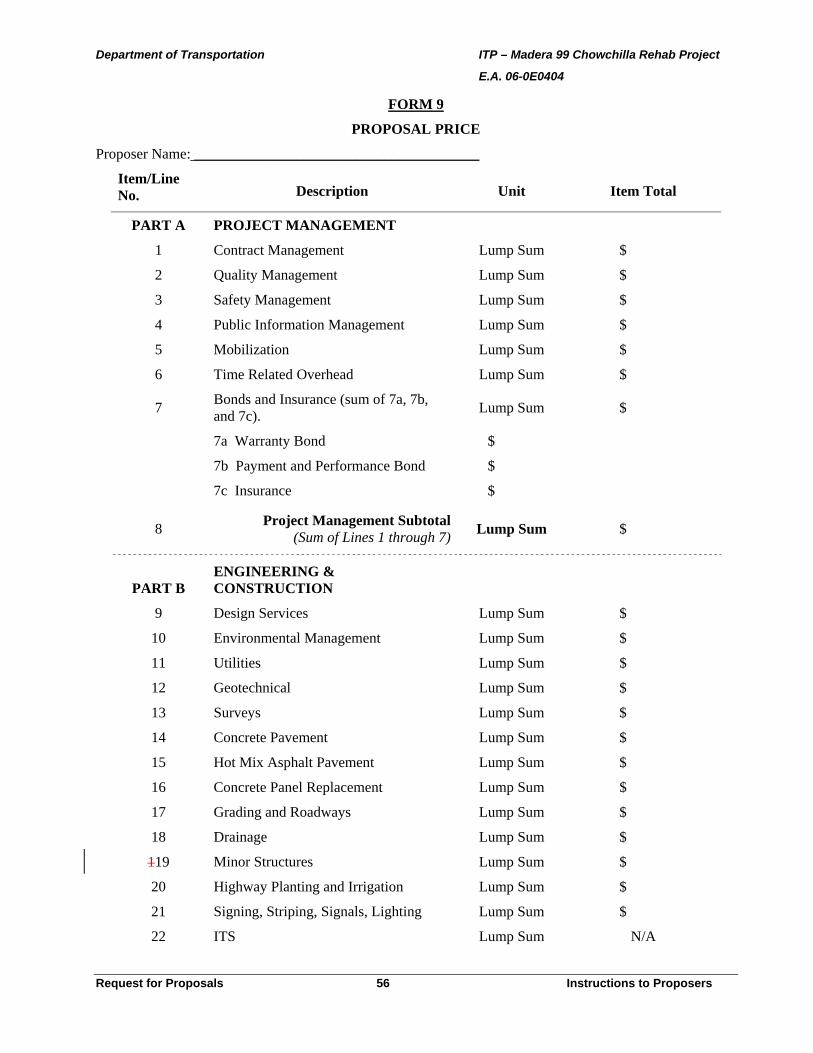
FORM 9
PROPOSAL PRICE
Proposer Name: _______________________________________
Item/Line No. Description Unit Item Total
PART A PROJECT MANAGEMENT
1 Contract Management Lump Sum $
2 Quality Management Lump Sum $
3 Safety Management Lump Sum $
4 Public Information Management Lump Sum $
5 Mobilization Lump Sum $
6 Time Related Overhead Lump Sum $
7 Bonds and Insurance (sum of 7a, 7b, and 7c). Lump Sum $
7a Warranty Bond $
7b Payment and Performance Bond $
7c Insurance $
8 Project Management Subtotal(Sum of Lines 1 through 7) Lump Sum $
PART B ENGINEERING & CONSTRUCTION
9 Design Services Lump Sum $
10 Environmental Management Lump Sum $
11 Utilities Lump Sum $
12 Geotechnical Lump Sum $
13 Surveys Lump Sum $
14 Concrete Pavement Lump Sum $
15 Hot Mix Asphalt Pavement Lump Sum $
16 Concrete Panel Replacement Lump Sum $
17 Grading and Roadways Lump Sum $
18 Drainage Lump Sum $
119 Minor Structures Lump Sum $
20 Highway Planting and Irrigation Lump Sum $
21 Signing, Striping, Signals, Lighting Lump Sum $
22 ITS Lump Sum N/A
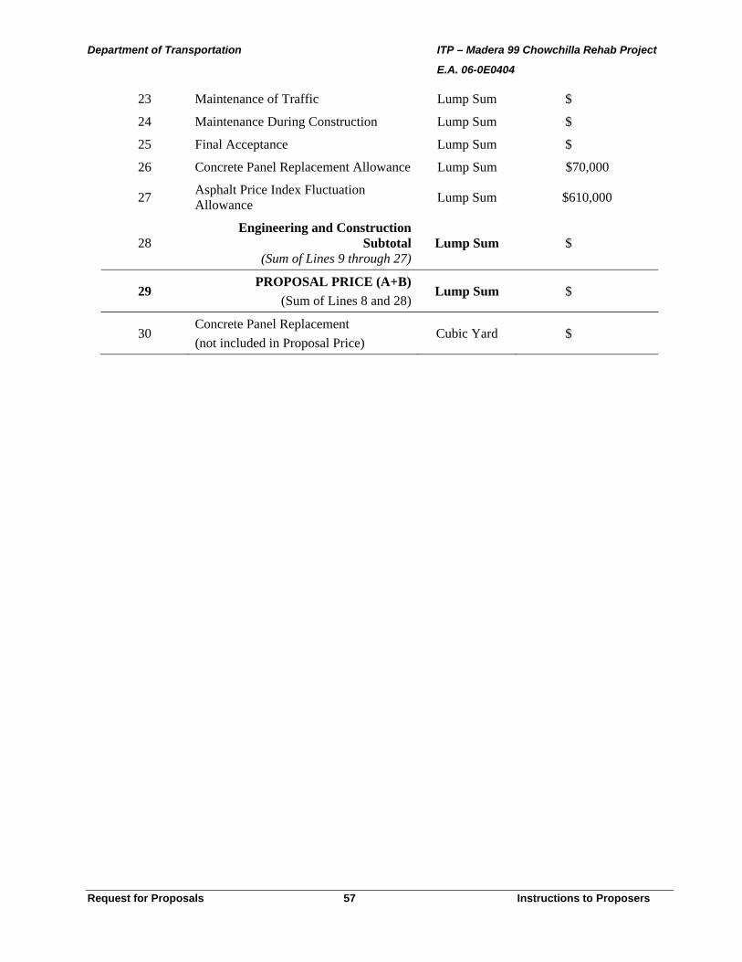
Department of Transportation ITP – Madera 99 Chowchilla Rehab Project
E.A. 06-0E0404
Request for Proposals 57 Instructions to Proposers
23 Maintenance of Traffic Lump Sum $
24 Maintenance During Construction Lump Sum $
25 Final Acceptance Lump Sum $
26 Concrete Panel Replacement Allowance Lump Sum $70,000
27 Asphalt Price Index Fluctuation Allowance Lump Sum $610,000
28 Engineering and Construction
Subtotal(Sum of Lines 9 through 27)
Lump Sum $
29 PROPOSAL PRICE (A+B)
(Sum of Lines 8 and 28)Lump Sum $
30 Concrete Panel Replacement (not included in Proposal Price)
Cubic Yard $
Department of Transportation Book 3 – Madera 99 Chowchilla Rehabilitation E.A. 06-0E0404 Project ID 0600000043
April 6, 2011 5-19 Modifications To Special Provisions
4. Controller Cabinets 86-335_E_T06-05-09
Department of Transportation Book 3 – Madera 99 Chowchilla Rehabilitation E.A. 06-0E0404 Project ID 0600000043
April 6, 2011 5-20 Modifications To Special Provisions
10-3.__ CONTROLLER CABINETS The Model 334 cabinets shall conform to the provisions in Section 86-3.01, "Controller Assemblies," of the Standard Specifications and these special provisions.
Cabinets furnished must be one listed on the April 9, 2008 Pre-Qualified Products List for Traffic Signal Control for Model 332A Cabinets or Model 334C Cabinets at:
http://www.dot.ca.gov/hq/esc/approved_products_list/pdf/traffic_signal_control.pdf
Cabinets shall be Model 334 and shall consist of a housing (A), a mounting cage 1, and the following listed equipment. The equipment shall conform to Chapter 6 of the Transportation Electrical Equipment Specifications (TEES).
1. Service panel No. 1 2. Power distribution assembly 3. Controller and equipment shelves 4. Dual fan assembly with thermostatic control
Police panels will not be required.
Prior to shipping to the project site, each Model 334 cabinet shall be submitted to the Transportation Laboratory for acceptance testing.
The Engineer shall be notified when each Model 334 cabinet is ready for the functional test. The functional test will be conducted by State forces.
The following equipment shall be provided with each power distribution assembly:
1. Two each of Duplex NEMA 5-20R controller receptacle 2. One each of 30 A, 1-pole, 120 V(ac) Main circuit breaker 3. One each of 15 A, 1- pole, 120 V(ac) circuit breaker 4. Two each of 20 A, 1- pole, 120 V(ac) circuit breaker
Three shelves shall be furnished. Each shelf shall be attached to the tops of 2 supporting angles with 4 screws. Supporting angles shall extend from the front to the back rails. The front of the shelf shall abut the front member of the mounting cage. The angles shall be designed to support a minimum of 50 pounds each. The horizontal side of each angle shall be a minimum of 3 inches. The angles shall be vertically adjustable.
Three terminal blocks shall be furnished. Terminal blocks shall conform to the requirements in Chapter 6 of the TEES, except that the screw size shall be 8-32.
A maintenance manual shall be furnished for all controller units, auxiliary equipment, vehicle detector sensor units, control units, and amplifiers. The maintenance and operation manuals may be combined into one manual. The maintenance manual or combined maintenance and operation manual shall be submitted at the time the controllers are delivered for testing or, if ordered by the Engineer, before purchasing. The maintenance manual shall include the following:

Department of Transportation Book 3 – Madera 99 Chowchilla Rehabilitation E.A. 06-0E0404 Project ID 0600000043
April 6, 2011 5-21 Modifications To Special Provisions
1. Specifications 2. Design characteristics 3. General operation theory 4. Function of all controls 5. Trouble shooting procedure (diagnostic routine) 6. Block circuit diagram 7. Geographical layout of components 8. Schematic diagrams 9. List of replaceable component parts with stock numbers
Department of Transportation Book 3 – Madera 99 Chowchilla Rehabilitation E.A. 06-0E0404 Project ID 0600000043
April 6, 2011 5-22 Modifications To Special Provisions
5. Wireless Modem 86-342X_E_D02-03-10

Department of Transportation Book 3 – Madera 99 Chowchilla Rehabilitation E.A. 06-0E0404 Project ID 0600000043
April 6, 2011 5-23 Modifications To Special Provisions
10-3.__ WIRELESS MODEM GENERAL The wireless modem must provide wireless data transmission between the field units and the Transportation Management Center (TMC). The modem and antenna must not cause any interference with any other electrical equipment in the cabinet. The wireless modem must be mounted in the cabinet as directed by the Engineer. Cable ties, wire mounting devices and fixed diameter clamps must be used in the controller cabinet and equipment rack to avoid physical interference between cables and adjacent equipment.
You must furnish, install, integrate, test and provide warranty for all equipment and components necessary to provide complete functionality of the wireless system. The wireless modem must consist of the modem, an external antenna, antenna cable, EIA-232 serial cable, and a power adapter.
The wireless modem must meet or exceed the following minimum requirements:
Wireless Modem Communications GPRS, EIA-485 and EIA-232 DTE Wireless Communications 1900/850 MHz GPRS/EDGE or 3G
Baud Rate Supported 1200, 2400, 4800, 9600, 19200, 28800, 38400, 57600, and 115200 bps
Serial Connector DB9M Input Voltage 10-30 V(dc) Power Consumption 1 Watt Operating Temperature From -35°C to +74°C Operating Humidity Range From 5 to 95 % non-condensing Standards Compliance PCCA STD-101 Network Protocols TCP, UDP, HTTP, SNMP,FTP, Serial over IP Persistent Network Connectivity
99. 2 % error free operation with auto reconnect
Status LED Indicators
Power, Receive, Transmit, RSSI( Signal Strength)
Network Port RJ45
SOFTWARE REQUIREMENTS The wireless modem must have firmware, software, hardware, and protocol features that must be fully compatible with the existing network and with the service provider . The software configuration package must be supplied for the wireless system at no extra cost. The control software configuration package must have features to provide for remote programming, remote maintenance, and system diagnostics.
ANTENNA The external antenna must be of a low profile design with integrated ground plane for outdoor permanent mount on a metallic structure. Before permanently installing the antenna, you must conduct signal strength measurements to verify signal strength per the manufacturer requirements. The antenna must be mounted at the top of the cabinet with antenna cable routed so as not to interfere with the fan assembly. Install the antenna and apply 100 percent clear silicon rubber sealant. For GSM dual band 850/1900MHz antenna connection, use a male SMA connector.

Department of Transportation Book 3 – Madera 99 Chowchilla Rehabilitation E.A. 06-0E0404 Project ID 0600000043
April 6, 2011 5-24 Modifications To Special Provisions
EIA-232 SERIAL PORT The modems must be configurable remotely through the wireless network or through the modem serial port. The modem must have the following DB9 pins.
Modem EIA-232 Signal
Cat 5 STP DB9M Plug Connector
Color Code Pin RD White/Blue 2 TD Blue 3 RTS Brown 7 CTS White/Brown 8 Signal GND White/Orange 5 DCD Orange 1 DTR White/Green 4 DSR Green 6
TESTING The modem must be configured and tested remotely. Proper operation of the modem must be demonstrated by successfully configuring the modem by modifying settings, checking the signal strength, and checking for status of the TCP/IP connection. The signal strength must be within the range of -50 dBm to –80 dBm. Perform visual check of the LED status lights to see that the LED lights are functioning properly.
CERTIFICATE OF COMPLIANCE You must provide the Engineer with a Certificate of Compliance from the manufacturer in accordance with the provisions of Section 6-1.07, "Certificates of Compliance," of the Standard Specifications for all modems furnished.
WARRANTY You must provide a written warranty from the manufacturer against defects in materials and workmanship for the wireless modem and assembly for a period of 12 months. Replacement of the modem must be provided within 5 days after receipt of failed wireless modem at no cost to the State, except the cost of shipping the failed parts. All warranty documentation must be given to the Engineer at the time of delivery.

Department of Transportation Book 3 – Madera 99 Chowchilla Rehabilitation E.A. 06-0E0404 Project ID 0600000043
April 6, 2011 5-25 Modifications To Special Provisions
6. Model 2070-6W Wireless Modem 86-349_E_D02-18-11

Department of Transportation Book 3 – Madera 99 Chowchilla Rehabilitation E.A. 06-0E0404 Project ID 0600000043
April 6, 2011 5-26 Modifications To Special Provisions
10-3.__ MODEL 2070-6W WIRELESS MODEM GENERAL This work includes installing Model 2070-6W wireless modems. Comply with Section 86, "Signals, Lighting and Electrical Systems," of the Standard Specifications and the Transportation Electrical Equipment Specifications (TEES).
MATERIALS The Model 2070-6W wireless modem must conform to Chapter 10, Section 5 of the TEES. You must furnish and install a wireless modem in each State-furnished Model 2070 controller assembly.
PAYMENT Full compensation for wireless modems is included in the contract lump sum price paid for the various items of work involved and no additional compensation will be allowed.

Department of Transportation Book 3 – Madera 99 Chowchilla Rehabilitation E.A. 06-0E0404 Project ID 0600000043
April 6, 2011 5-27 Modifications To Special Provisions
7. Vehicle Classification Station 86-451X_E_D04-06-11
Department of Transportation Book 3 – Madera 99 Chowchilla Rehabilitation E.A. 06-0E0404 Project ID 0600000043
April 6, 2011 5-28 Modifications To Special Provisions
10-3.__ VEHICLE CLASSIFICATION STATION The work includes furnishing and installing a vehicle classification station (VCS) consisting of a Model 334 cabinet, automated traffic counter, inductive loop detectors, piezo axle sensors, screened transmission cables, and the required wiring and auxiliary equipment required for a fully functional system as shown on the plans and in conformance with these special provisions.
MODEL 334 CABINET Model 334 cabinets shall conform to the provisions in "Controller Cabinets" of these special provisions.
AUTOMATED TRAFFIC COUNTER The automated traffic counter (ATC) must collect data for traffic volume, vehicle speed and vehicle classification from permanently installed sites. The ATC must be capable of storing data, generate reports and provide outputs in suitable format to Caltrans Transportation System Network (TSN) database.
ATC Hardware Requirements ATC must meet the provisions for connecting the following inputs:
1. 8 inputs for piezoelectric axle sensors 2. 16 inputs for inductive loop detectors
ATC Requirements The ATC shall meet the following specifications:
1. Construction - All traffic data collection equipment and accessories must be of solid state construction with no moving or wearing parts, exclusive of switches and keypads.
2. Operating Temperature Range - From –40 to +158 °F minimum. 3. Noise - Equipment must be resistant to electromagnetic noise, electrostatic discharges, and
induced power supply fluctuations. The signal-to-noise level shall be equal to or greater than 10:1.
4. Lane/Direction - Equipment must be capable of sensing, collecting, and recording data by lane. Number and direction of lanes shall be user configurable.
5. Internal Clock - The equipment must have continuous date (corrected for leap years) and time (24 hour). The internal clock must continue to keep the correct time even when the primary battery is completely discharged or disconnected.
6. Loop Separation - The loop sensor separation (spacing - leading edge to leading edge) must be a user-programmable parameter by lane.
7. Piezo Separation - The piezo sensor separation must be a user-programmable parameter by lane. 8. Memory Retention During Power Loss - Data stored in memory must not be lost when the
battery of the unit is completely discharged or disconnected. 9. Data Overwrite - The counter must provide RAM memory that utilizes first-in, first-out (FIFO),
also known as wrap around, so that when memory is filled the most recent observations replace the oldest observations.
10. Vehicle Density - The maximum vehicle density measured by the ATC must be three vehicles per lane per second.

Department of Transportation Book 3 – Madera 99 Chowchilla Rehabilitation E.A. 06-0E0404 Project ID 0600000043
April 6, 2011 5-29 Modifications To Special Provisions
11. Operating Speed Range - The operating speed range of the unit must be from 5 to 95 miles per hour.
12. Count Storage Capacity - The unit must be able to detect, count, measure speed and classify at least 3,600 vehicles per lane per hour.
13. Memory Capacity - The internal RAM of the unit must be capable of storing a minimum of 45 days of data in hourly interval or bins, in a configuration that stores data for at least eight lanes.
14. Time Intervals - Time intervals must be user programmable with intervals of thirty seconds, one minute, five minute, ten minutes, fifteen minutes, sixty minutes and twenty four hours.
15. Rack Mountable - Shall have the option to mount in an EIA 19 inch rack.
Power
The ATC shall be powered with 120 V(ac) or a 12 V(dc) photovoltaic power supply with battery back up as shown on the plans.
Accuracy
The ATC equipment must meet the following accuracy standards:
1. Accuracy of Traffic Volumes Counts - ± 3 percent with 95 percent accuracy level. 2. Accuracy of Vehicle Classification - Within ± 4 %. 3. Number of Vehicle Classification Bins - Vehicles must be classified into a minimum of fifteen
user-programmable bins. 4. User-Programmable Classification Parameters - Users must be able to program the algorithms for
axle spacing for all classes. 5. Default Vehicle Classification Scheme - Shall be user programmable.
Accessories
You must provide all accessories that are necessary for making the equipment fully functional and tested. The following cables shall be furnished:
1. Laptop to ATC cable 2. ATC to sensor port cable for each port on the ATC
Software Requirements
Data Retrieval
You must provide all communication software. Access to stored data in the ATC must be available through personal computers, both laptop and desktop with Windows XP, Windows 7, or newer operating system via standard EIA-232 interface. Remote access shall be available through a modem, either hard wired or wireless.
Communications
Communications, either in the field or from the office, via direct connection or wireless modem must support all programmable features and shall include the following applications:

Department of Transportation Book 3 – Madera 99 Chowchilla Rehabilitation E.A. 06-0E0404 Project ID 0600000043
April 6, 2011 5-30 Modifications To Special Provisions
1. Real Time View - The real time view application shall provide for on-line monitoring of traffic. The display on the traffic census host computer shall indicate the number of vehicles passing within the time interval and update each passage. If programmed for vehicle classification, the display on the traffic census host computer shall depict the axle type and speed of each vehicle passing through the site. The user shall have the option of displaying either all traffic or only vehicle classifications as well as the option of displaying a selected individual lane or all lanes.
2. System Data Programming - The system data programming application shall provide for on-line modification to the ATC.'s software parameters, such as speed, axle spacing factors, loop and piezo sensitivity settings. System shall be password protected.
3. Manual Downloading - The manual downloading application shall be capable of downloading selected daily data files from the storage medium of the ATC to the storage medium of the traffic census host computer. The program shall provide for a listing of the daily data files stored in the ATC and shall provide for user selection of the file or files to be downloaded. The program shall provide for the downloading of the current day's data stored as of the time of downloading.
4. Automatic Downloading - When required, the automatic downloading application shall provide for unattended downloading of daily data files stored in the ATC's storage medium to the traffic census host computer. The program shall provide the following:
4.1 User's input for the date and time that unattended downloading is to begin. 4.2 Downloading of all daily files not previously downloaded by the automatic down loading
application. 4.3 Program shall indicate when any interrupted or incomplete file download has occurred. 4.4 Discontinuation of telephone connection after downloading of files from the ATC (or after
an abort) and returning the traffic census host computer to a standby mode. The polling feature in communications software must support a telephone directory with a minimum of 200 sites where the user can add, change, or delete any data in a directory record.
5. History file - The history file application shall create a daily file that chronologically records the events occurring during manual and automatic downloading sessions. Such events shall include, but not be limited to, modem result messages, and start and end time of each file being downloaded and any pertinent messages generated by the program. The programming shall provide either:
5.1 The history file shall be in the form of an ASCII text file which can be viewed or sent to
the printer or, 5.2 A menu selection which shall provide for a listing of available history files and user
selection of a file to be sent to the printer in the form of a report.
Retrieved data must include information to produce the data formats specified in Attachment 1, 2, and 3 "ASCII Speed and Classification Formats."
The communications portion of the system program shall meet the following functional requirements:
1. Baud Rate - The programming will provide for operation at a minimum baud rate of 9600. 2. Error Control - The program shall not in any way disable the modem’s error-checking features,
which prevent phone-line noise from corrupting data during file downloading. 3. File Downloading Monitoring - The program shall display a window that allows the user to
monitor the progress of file downloading. The program shall also provide for the abort of a file download.

Department of Transportation Book 3 – Madera 99 Chowchilla Rehabilitation E.A. 06-0E0404 Project ID 0600000043
April 6, 2011 5-31 Modifications To Special Provisions
INDUCTIVE LOOP DETECTORS Inductive loop detectors for vehicle classification station and the installation thereof shall conform to the provisions in "Detectors" of these special provisions.
PIEZO AXLE SENSORS Piezo axle sensors shall be Class II and use for vehicle classification purposes. Piezo axle sensors shall consist of a piezo-electric copolymer surrounded by a 1/64" thick outer brass sheath. Each sensor shall be 1/4" wide x 1/16" thick x 6' long with a screened transmission cable (STC) attached. The Engineer will determine the exact location of the inductive loop detector/piezo axle sensors.
The piezo axle sensor shall be installed in a channel as shown on the plans, per manufacturer's specifications, and as directed by the Engineer. The channel shall be filled with epoxy grout. The epoxy grout shall consist of an acrylic resin and a benzoyl peroxide catalyst. The grout shall not exceed 76 °C while curing, and shall be adequately set before re-opening the lane to traffic.
All sawed pavement slots containing screened transmission cable shall be filled with elastomeric sealant. Elastomeric sealant shall conform to Section 86-5.01A(5), "Installation Details" of the Standard Specifications.
Piezo axle sensors shall meet or exceed the following requirements:
Performance Requirements Output Uniformity ±20% Operating Temperature Range
-40° to +70°C
Typical Output Level A wheel load of 400 pounds will produce a minimum output signal of 250 mV, at 21°C and 55 mph.
Signal-to-Noise Level The signal-to-noise level shall be equal to or greater than 10:1
Insulation Resistance >500 Mohms Product Life Equivalent Single Axle Loadings (ESAL)
SCREENED TRANSMISSION CABLE Screened transmission cable (STC) shall be RG-58C/U coaxial cable with a high density polyethylene outer jacket. STC shall be rated for direct burial. Sufficient STC to reach the cabinet shall be supplied with each axle sensor. The STC shall not be spliced. STC terminations shall be made using properly sized captive or spring spade type terminals, crimped and soldered.
ACCEPTANCE TESTING The Contractor must provide test equipment and documentation that the equipment meets performance specifications and accuracy requirements outlined above. The Contractor must provide the Engineer with documentation that supports the accuracy analysis.

Department of Transportation Book 3 – Madera 99 Chowchilla Rehabilitation E.A. 06-0E0404 Project ID 0600000043
April 6, 2011 5-32 Modifications To Special Provisions
The Contractor must demonstrate that the vehicle classification station is available for use by the State by successfully completing the acceptance test for each lane of data collection.
The acceptance test shall consist of the following:
1. Loop detectors shall be tested according to the procedure in Section 86-2.14B, "Field Testing" of the Standard Specifications.
2. Piezo axle sensors shall be tested as follows: a) Capacitance shall be 20% of the sensor’s data sheet as provided by the manufacturer. b) Dissipation factor shall be less than 0.04 when measured in the 20 nF range. c) Resistance shall be greater than 20 Megohms.
3. A minimum of 100 per-vehicle records shall be collected for each lane. Collected data must meet the following accuracy standards: a) Total volume ±3% with 95% accuracy b) Vehicle classification 95% accurate classification by type.
4. Correct functioning of the communications link shall be verified by collecting data files from the on-site equipment with the traffic census host computer.
5. Continuous operation of the vehicle classification system on-site equipment be checked for 5 consecutive days. Failure of the system to record and store data meeting the requirements set forth in these special provisions for an accumulated time exceeding 3 hours during the 5-day period shall be cause for the acceptance test to be rejected and repeated.
6. Failure of the software to perform any application required in these special provisions shall be cause for the acceptance test to be rejected and repeated.
ATC Functional Acceptance To be considered fully functional, an individual ATC unit must:
1. Collect data locally and remotely meeting the accuracy specifications for a minimum of 30 continuous days
2. Successfully process downloaded files for input in Caltrans TSN database
TRAINING The Contractor shall provide a minimum of 6 hours of training by a certified manufacturer’s representative for up to 8 students selected by the Engineer. The content of the training shall include instruction on how to wire a sensor to the ATC, configure and program an ATC, download - locally and remotely- ATC data using a traffic census laptop or computer and maintain the VCS. The Contractor shall provide materials and equipment for the training. The Contractor shall give the Engineer 15 days notice prior to the training. The time and location of the training shall be agreed upon by the Engineer and the Contractor. If no agreement can be reached, the Engineer shall determine the time and location.
WARRANTY The Contractor must provide a written warranty of the manufacturer against defects in materials and workmanship of the equipments for a period of 24 months. The warranty for each unit will begin when the equipment is installed and commissioned in the field and is fully functional. A completed form will be returned to the Contractor for each unit certifying that the unit has been fully functional on the date specified.

Department of Transportation Book 3 – Madera 99 Chowchilla Rehabilitation E.A. 06-0E0404 Project ID 0600000043
April 6, 2011 5-33 Modifications To Special Provisions
The warranty will include repair or replacement of defective components including two-way shipping charges by the State’s district office that owns the equipment. Repair or replacement of any traffic data collection device is expected to be accomplished within five working days of receipt at the manufacturer's repair facility of the defective equipment returned by the State.
MANUALS The Contractor must provide 10 copies of all user and operator manuals, technical briefs or other documentation for the units and accessories for equipment installation and commissioning; software installation and operation; and system and unit diagnostics and repair.
PAYMENT The contract lump sum price paid for vehicle classification station includes full compensation for furnishing all labor, materials, tools, equipment, and incidentals, and for doing all the work involved in vehicle classification station, complete in place, as shown on the plans, as specified in the Standard Specifications and these special provisions, and as directed by the Engineer.
Department of Transportation Book 3 – Madera 99 Chowchilla Rehabilitation E.A. 06-0E0404 Project ID 0600000043
April 6, 2011 5-34 Modifications To Special Provisions
8. Closed Circuit Television System 86-CCTV_E_D09-16-10

Department of Transportation Book 3 – Madera 99 Chowchilla Rehabilitation E.A. 06-0E0404 Project ID 0600000043
April 6, 2011 5-35 Modifications To Special Provisions
10-3.__ CLOSED CIRCUIT TELEVISION SYSTEM GENERAL The closed circuit television (CCTV) system shall conform to all rules and regulations of the Federal Communications Commissions and shall conform to the provisions in Section 86, "Signals, Lighting and Electrical Systems," of the Standard Specifications and these special provisions.
The existing CCTV system deployed in the district is the Pelco ES30C, Model #ES30CBW24-5N, with SMR1-DCWG7. The existing camera assembly is mounted on a pedestal mount. The existing pedestal mount deployed in the district is the Pelco PM2010-Pedestal Mount with SMR1-1A3JIS. The new system furnished by the Contractor shall be compatible with the existing CCTV system and these special provisions.
Each CCTV system shall consist of providing electrical service, furnishing and installing a camera assembly, video encoder, a camera pole, Model 334 cabinet, composite cable and wiring, and other required equipment as shown on the plans. Testing of all CCTV equipment shall be performed after installation as described elsewhere in these special provisions.
All components of the camera assembly shall have a minimum 2-year manufacturer's warranty for parts and labor. Warranty periods shall begin the day the contract is accepted.
The Contractor shall fill out and mail equipment warranties of all camera equipment under "CALTRANS District 06, 1352 West Olive Avenue, Fresno, California 93722." Copies of mailed warranties with serial numbers shall be submitted as part of the system documentation.
CAMERA ASSEMBLY The camera assembly shall consist of the camera and positioner components integrated into one unit.
The camera component shall meet or exceed the following requirements: an imager with a ¼” color charge-coupled device (CCD), NTSC horizontal resolution of 520 lines, optical zoom range of 24X, 4 mm to 88 mm and auto/manual focus, and camera shall be enclosed in a sealed housing.
The positioner component shall meet or exceed the following requirements: an angular travel of 360 degrees continuous pan and –83 to +33 degree tilt ranges.
VIDEO ENCODER The existing video encoder deployed in the district is the Axis 241S. The new video encoder furnished by the Contractor shall be compatible with the existing CCTV system and these special provisions.
COMPOSITE CABLE The existing composite cable deployed in the district is the Cohu CA290 series, Model #CA297H with a 4 foot Model # CA297G pigtail cable installed in the Model 334 cabinet. The new cable system furnished by the Contractor shall be compatible with the existing CCTV system and these special provisions.
The composite cable shall provide video, data, and power conductors in a single jacketed cable. The cable shall have a strain relief located towards the top of the CCTV pole and hung on the pole j-hook.
Wiring shall run continuous from source to destination. No splices shall be allowed.
The Contractor shall verify composite cable length prior to ordering of materials and shall use a vendor manufactured and tested cable.

Department of Transportation Book 3 – Madera 99 Chowchilla Rehabilitation E.A. 06-0E0404 Project ID 0600000043
April 6, 2011 5-36 Modifications To Special Provisions
CCTV POLE CCTV poles shall conform to the provisions in Section 86-2.04, "Standards, Steel Pedestals and Posts," of the Standard Specifications and these special provisions.
MODEL 334 CABINET Each Model 334 cabinet shall meet the requirements as shown on the plans and specified elsewhere in these special provisions and the following requirements.
Surge Protector The Contractor shall furnish and install a surge arrestor, which shall reduce the effect of power line transients and rated as follows:
Recurrent Peak Voltage 184 V Energy Rating (Minimum) 20 J Power Dissipation, Average 0.85 W Peak Current for pulses less than 7 microseconds 1250 A Stand-by Current for 60 Hz Sinusoidal 1 mA or less
TESTING AND DOCUMENTATION Once the CCTV System is installed the Contractor shall conduct tests of the CCTV system in accordance with these special provisions.
Transportation Management Center personnel prior to acceptance of CCTV System shall be present for the testing of the CCTV System.
Each CCTV camera shall be tested after installed in place on the pole. In the Model 334 cabinet the camera video output cable will be connected to a Contractor-furnished NTSC color monitor and the pan/tilt/zoom communications link will be connected to a State-furnished portable laptop computer configured to the Pelco D protocol. State forces will make available the portable laptop computer (PC) with Pelco D protocol for testing purpose only. The PC will remain State property and must be returned to the State by the Contractor upon successful completion of the test. The tests performed are:
A. Video quality observed on the NTSC color monitor as the lens focal lengths and apertures of the lens are varied and verifying the correct operation of the auto focus.
B. Pan/tilt/zoom ranges as specified in these Special Provisions for the CCTV Camera. C. Preset storage: two presets will be stored in the CCTV Camera memory and observed for accurate
positioning for a minimum of five cycles of pan/tilt/zoom movement.
Documentation of all test results shall be provided to the Engineer for review and approval. System documentation shall incorporate the test results for ongoing maintenance and performance measurements.
The Contractor shall be responsible for all deliveries.

Department of Transportation RID – Madera 99 Chowchilla Rehabilitation E.A. 06-0E0404 Project ID 0600000043 _________________________________________________________________________________________________________________________________
_________________________________________________________________________________________________________ April 07, 2011 1 Index of Reference Information Documents
Index of Reference Information Documents A “W” under available column indicates documents that can be found on the Internet, an “E” indicates the document will be provided electronically, and “CO” indicates the Contractor shall obtain the document. Web sites are not guaranteed but are supplied for information. It is ultimately the Contractor’s responsibility to locate the documents.
Title Available
EXISTING INFORMATION
RW Maps 001-018 Portfolio.pdf – Existing Right-of-Way Maps W
Utility Search.pdf – Existing Utilities W
As-Built Plans Folder
06-328104.pdf – June 29, 1995 Plans in and near Madera from Route 145/99 Separation to Avenue 16 Overcrossing PM 10.2/12.8 W
06-400604.pdf – January 06, 1999 Plans in Madera from 0.5 km south of the South Madera Overcrossing to the Route 145/99 Separation KP 15.2/16.9 W
58-6TC2.pdf – January 21, 1957 Plans between 0.5 mile south and 1.5 miles north of Madera W
Pump House Cleveland PM12.12.pdf – Cleveland Avenue Overcrossing Pumping Plant W
Pump House Madera Ave.pdf – Route 145/99 Separation Pumping Plant W
Pump House Madera Underpass.pdf – Madera Underpass Pumping Plant W
06-0E0404 Mad 99 Additional As-Built Plans.zip – Zipped file containing 6 more additional As-Built Plans W
06-0E0404 Mad 99 Structures As-Built Plans.zip – Zipped file containing 9 Structures As-Built Plans W

Department of Transportation RID – Madera 99 Chowchilla Rehabilitation E.A. 06-0E0404 Project ID 0600000043 _________________________________________________________________________________________________________________________________
_________________________________________________________________________________________________________ April 07, 2011 2 Index of Reference Information Documents
Title Available
EXISTING INFORMATION (CONTINUED)
CAiCE and Survey Files Folder
0E0401.zip – 56 CAiCE and Survey Files in a zip file W
Survey File PM 12.6 to PM13.1.pdf – Survey Request SR 0906-0005 and Completion Memos W
Allpts.doc – Survey Point Listing File W
PROJECT STUDIES AND REPORTS
Hydraulics Recommendation.pdf – PS&E Hydraulics Recommendation W
Materials Recommendation.pdf – Flexible Deflection Studies Report and the Rehabilitation Recommendations W
Project Scope Summary Report.pdf – Signed Project Scoping Summary Report W
Railroad Clearance and Sec 13.pdf – Railroad Clearance and Short Clauses for Special Provisions W
Site Investigation Report - Geocon 40060.pdf – Aerial Lead Site Investigation Report for EA 06-40060K dated 03/09/98 W
Site Investigation Report - IT Corp 4036U.pdf – Aerial Deposited Lead Study for EA 06-4036U1 dated 08/16/00 W
Utility Encroachment Permit Request.pdf – Request for Utility Longitudinal Encroachment Exception W
Value Analysis Report.pdf – Final Value Analysis Study Report prepared by Value Management Strategies, Inc. W
06-0E0401 Longitudinal Encroachment Exception.pdf – Approved Exception for existing AT&T Underground Telecommunications Facilities W
06-0E0401 RFP RID Supplemental Material Recommendations Addendum No 2.pdf – Supplemental Material Recommendations for project limits PM 10.00 to PM 10.10 and PM 10.45 to PM 11.60 W

Department of Transportation RID – Madera 99 Chowchilla Rehabilitation E.A. 06-0E0404 Project ID 0600000043 _________________________________________________________________________________________________________________________________
_________________________________________________________________________________________________________ April 07, 2011 3 Index of Reference Information Documents
Title Available
Traffic Study Report Folder
Planning Design Designation.pdf – Design Designation for Madera 99 at the project location W
Safety Analysis.pdf – Updated Safety Analysis provided by the Office of Traffic Operations W
Transportation Management Plan.pdf – Transportation Management Plan for reference only. Please use the Lane Requirement Chart Guidelines included in Book 2 for the development of the Lane Closure Charts W
Safety Analysis Update - Traffic Operation.pdf – Updated Safety Analysis dated January 10, 2011 W
06-0E0404 Mad 99 Materials R-Values.zip – Zipped 15 Materials Report of Test on Soil Design Samples W
Deflection Study.pdf – Flexible Pavement Deflection Study Report dated December 22, 2009 W
CONCEPTUAL PLANS
06-0E040 Mad 99 Rehab Plans.pdf – PDF File of all the conceptual plans W
60E040ua007.pdf – Missing Electrical Plan Sheet E-7 on Count Loops Modify Lighting W
0e0401 Pre-Bid Meeting Display.pdf – Display posted at the Pre-Bid Meeting W
06-0E0401 RFP RID Revised Typical XSect X1, X2 & X3 Addendum No 2.pdf – Revised Typical Cross Section Plan Sheets X1, X2 & X3 dated 03-25-11 W