Embed Size (px)
Citation preview

89087-9365(3)
CITY OF RICHMOND
REQUEST FOR PROPOSAL PROPOSAL No. 2759-P INDEPENDENT COMMISSIONING AUTHORITY: -LEED® FUNDAMENTAL AND ADDITIONAL COMMISSIONING -COMPREHENSIVE TECHNICAL COMMISSIONING RICHMOND OLYMPIC OVAL RICHMOND, BC March 8, 2006
RFP for Independent Commissioning Authority Richmond Olympic Oval City of Richmond, BC
1 of 29
REQUEST FOR PROPOSAL Proposal No. 2759-P INDEPENDENT COMMISSIONING AUTHORITY -LEED® FUNDAMENTAL AND ADDITIONAL COMMISSIONING -COMPREHENSIVE TECHNICAL COMMISSIONING RICHMOND OLYMPIC OVAL RICHMOND, BC Proposal submissions clearly marked RFP # 2759-P for Independent Commissioning Authority, Richmond Olympic Oval, Richmond, BC will be received at the Information Counter, Main Floor, Richmond City Hall, 6911 No.3 Road, Richmond BC, V6Y 2C1, until 2:00 pm, local time on Thursday, March 23, 2006. Submissions received after this time will be returned to the sender unopened. Faxed proposals will not be accepted. The City of Richmond (The City) requests written proposals to secure Commissioning Authority (CA) services for the Richmond Olympic Oval project. The City is committed to commissioning this facility to ensure that all systems function as designed upon occupancy, and that the City’s Maintenance Staff has adequate system access, control, monitoring capabilities, documentation and training to properly monitor, manage and maintain the facility. The City is seeking the services of a qualified Commissioning Authority for a new construction project, Richmond Speed Skating Oval, a project designed on the principles of sustainable development and the CAGBC LEED framework. The City has registered the Oval project under the LEED® Silver certification level. The project is a multi-purpose sports and community wellness centre containing ice sheets, filed house, gymnasium courts, high-performance fitness centres. The facility will host World Cup championships for Long-track Speed Skating starting in 2008 and the Vancouver Winter Olympics in 2010. The project is to be constructed for an approximate value of $178,000,000 not including GST. The project is at the Design Development Stage. Works on site preparation (soil densification, preload…) has already started. The construction documents will be prepared in sequential mode in accordance to the Tender Packages, and will be completed by September 2006, including the Main Mechanical package. Extracts from the Schematic Design Report for the Richmond Olympic Oval, dated January 2006, is included in this RFP package for your information. Initial occupancy is planned for September 8, 2008. Project documents are not available for review at this stage but a non-mandatory Q&A session will be held on Tuesday, March 14 for the proponents. The City reserves the right to reject any or all RFP’s or to accept any RFP’s, should it be deemed in the best interest of the City to do so. All inquiries are to be directed to Guillaume Savard, PMP, Project Manager, MHPM Project Managers, Email: [email protected] or Fax: (604) 714-0989.

RFP for Independent Commissioning Authority Richmond Olympic Oval City of Richmond, BC
2 of 29
TABLE OF CONTENTS Page REQUEST FOR PROPOSAL 1 TABLE OF CONTENTS 2 SECTION 1. - INTRODUCTION 3 SECTION 2. - GENERAL CONDITIONS 4 - 9 SECTION 3. - SCOPE OF WORK 10 - 19 SECTION 4. - INFORMATION REQUIREMENTS 20 - 22 SECTION 5. - APPENDICES 23- 29
01 – Project Profile 02 – Schematic Design Report (extracts on technical systems) 03 – Project Master Schedule 04 – Stantec’s typical Commissioning specifications for Mechanical 05 – Stantec’s typical Commissioning specifications for Electrical 06 – Table A: Commissioning Firm Experience
07 – Table B: Commissioning Personnel Experience 08 – Table C: Approach & Methodology 09 – Table D: Proponent’s Workplan 10 – Table E: Cost Proposal

RFP for Independent Commissioning Authority Richmond Olympic Oval City of Richmond, BC
3 of 29
1.0 INTRODUCTION 1.1 OVERVIEW The City of Richmond (The City) requests written proposals to secure Commissioning Authority (CA) services for the Richmond Olympic Oval project. The City is committed to commissioning this facility to ensure that all systems function as designed upon occupancy, and that the City’s Maintenance Staff has adequate system access, control, monitoring capabilities, documentation and training to properly monitor, manage and maintain the facility. 1.2 BACKGROUND The City is seeking the services of a qualified Commissioning Authority for a new construction project, Richmond Olympic Oval, a project designed on the principles of sustainable development and the CAGBC LEED framework. The City has registered the project under a Silver certification. The project is a multi-purpose sports and community wellness centre containing ice sheets, filed house, gymnasium courts, high-performance fitness centres, totalling 52,000 sq.m. including an interior parkade. The facility will host World Cup championships for Long-track Speed Skating starting in 2008 and the Vancouver Winter Olympics in 2010. The project is to be constructed for an approximate value of $178,000,000 excluding GST. Appendix 01 presents a more detailed Project Profile. The project will be owned and operated by the City of Richmond. The City is the developer of the project, with the Vancouver Olympic Organizing Committee (VANOC) providing a $60M contribution to capital cost. The project is at the Design Development stage. Works on site preparation (soil densification, preload…) has already started. The construction documents will be prepared in sequential tender package mode and be completed by September 2006. Under appendix 02, extracts from a draft Schematic Design Report are included in this RFP package for your information. The latest Project Master Schedule is included in appendix 03. 1.3 OBJECTIVES The objective of comprehensive commissioning is to provide documented confirmation that the facility fulfills the functional and performance requirements of Richmond Olympic Oval as well as the CAGBC LEED Green Building Rating System® fundamental and additional commissioning requirements. To reach this goal, it is necessary for the CA to establish and document the City’s criteria for system function, performance, and maintainability; as well as, to verify and document compliance with these criteria throughout design, construction, start-up, and warranty period. The delivery of operation & maintenance manuals, re-commissioning management manual, and staffing training is also part of the CA mandate in order to ensure the building continues to operate as intended. The CA will be involved in the project from the design phase through the warranty phase.

RFP for Independent Commissioning Authority Richmond Olympic Oval City of Richmond, BC
4 of 29
2.0 GENERAL CONDITIONS This section defines the general requirements and procedures for submission of proposals by Proponents. Proponents are cautioned to carefully read the RFP documents and follow the procedures identified; deviation from the procedures may be cause for rejection of the proposal. 2.1 Cost of Proposal The preparation and submission of a proposal in response to this Request for Proposal (the “RFP”) is voluntary and any costs associated with such preparation and submission is solely that of the party (the “Proponent”) submitting the proposal. 2.2 Acceptance of Proposal The City reserves the right to reject any or all proposals or to accept any proposal received in response to this RFP, should it be deemed in the best interest of the City to do so. The City is under no obligation to proceed with the RFP and, should it decide to abandon the same, it may at any time cancel the RFP, and invite further RFP’s or such other submissions for the provision of the services, or enter into any discussions or negotiations with any party for the provision of such services. 2.3 All Proposals Public All proposals submitted to the City will be received and held in confidence, and will become the property of the City. The City is bound by the provisions of the Freedom of Information and Protection of Privacy Act. All Proponents submitting proposals pursuant to this RFP are advised that such proposals will be treated as public documents and the contents of the same disclosed upon written request if required to do so pursuant to the Act. 2.4 Closing Date In addition to one signed original, five (5) complete legible copies of any proposal submitted in response to this RFP will be received at the Information Counter, Main Floor, Richmond City Hall, 6911 No.3 Road, Richmond BC, V6Y 2C1, until 2pm, local time on Thursday, March 23, 2006 (the “Closing Date”). Submissions received after this time will be returned to the sender. Faxed proposals or amendments will not be accepted. 2.5 Acceptance Period for Proposals All proposals received as a result of this RFP must be open for acceptance for a period of 90 days from the Closing Date. 2.6 No Binding Contract The proponent, by submitting a proposal, agrees that it will not make any claim relating to the proposal or in respect of the competitive process, and the proponent, by submitting a proposal, waives any claim for loss of profits if no agreement is made with the proponent.

RFP for Independent Commissioning Authority Richmond Olympic Oval City of Richmond, BC
5 of 29
The City may, after reviewing the proposals received, enter into discussions with one or more of the Proponents, without such discussions in any way creating a binding contract between the City and any such Proponent. There will be no binding agreement with the City until a formal, written agreement has been negotiated with a Proponent and that agreement has been approved by the City. The Proponents are advised that the City is under no obligation and does not make any commitments to the successful Proponent for the award of any future works as a result of this RFP process. 2.7 Evaluation Criteria for Proposals The proposals will be evaluated and Proponents advised accordingly on the selection. Completeness and thoroughness of proposal submitted in response to this RFP and apparent enthusiasm and commitment to the project are pre-requisites to the evaluation and scoring. The City will evaluate each proposal received in response to this RFP using the following criteria, and each should be referenced in the RFP submission and also referring to Section 4 of this proposal: Points Table Firm’s experience (similar project, experience, depth…) 10 A Demonstrated ability and experience of the senior personnel of the Proponent 30 B
and of the Proponent’s personnel assigned to this project, in providing the full scope of services on comparable projects,
Approach to LEED® & comprehensive commissioning, and Degree of 10 C understanding of the project, issues and requirements in a project of this nature.
Management and Administration (level of skills and experience, 10 C report preparation, communication skills, presentation of ideas, team work ability)
Level of time and effort the Proponent is proposing and identifying intended 10 D deliverables of the RFP,
The costs and benefits to the City, 30 E The total scoring is 100 points and proponents will be ranked accordingly. 2.8 Communications with Proponents If the City deems it necessary to hold a briefing for this RFP, the Proponents will be advised of the place, date and the time. It is each Proponent’s responsibility to ensure that it seeks clarification on any matter relating to this RFP. Requests for clarification must be made in writing by fax or by email to the contact noted below. All inquiries shall be submitted prior to at least three (3) working days from the Closing Date.
Guillaume Savard, arch., M.Eng., PMP Project Manager MHPM Project Managers Fax: (604) 714-0989 Email: [email protected]

RFP for Independent Commissioning Authority Richmond Olympic Oval City of Richmond, BC
6 of 29
Information obtained from any other source is not official and should not be relied upon. Enquiries and responses will be recorded and may be distributed to all Proponents. 2.9 Addenda Addenda, bulletins or corrections may be issued by the Project Manager (MHPM) through the City prior to the Closing Date and should be included in and submitted with the proposal, and shall become part of any final contract. Failure to enclose these documents with the submission may result in rejection if the City, under its sole discretion, determines the exclusion significantly impacts the proposal. Any interpretation of, additions to, deletions from, or any other corrections to the Contract documents, will be issued as written addenda by the City of Richmond. It is the sole responsibility of the potential bidders to check with BCBid, the City of Richmond’s Website and/or Purchasing Section to ensure that all available information has been received prior to submitting a bid. 2.10 Assignment No Proponent may assign its proposal or any rights in respect of the same to any other party. Such an assignment or purported assignment will immediately invalidate the Proponent’s proposal. 2.11 Canadian Currency All monetary references in a proposal must be to Canadian currency. Prices quoted will be exclusive of all taxes. 2.12 Valid Authority All proposals must be signed by the Proponent. Any corporate Proponent must ensure that the proposal is signed by its authorized signatory or signatories. In case of a joint submission, Proposals must be signed by an authorized signatory for the Proponent or Proponent group. 2.13 Interviews Subsequent to the submission of Proposals, the City may, at its sole discretion, interview and/or request a more detailed presentation from one or more of the Proponents. Proponents may be required to provide additional information, including supplying previous work examples, additional references and/or additional literature. 2.14 Payments and Invoicing Invoice amounts in excess of the agreed costs will not be accepted. If the overall project exceeds the agreed to timing, a written request must be submitted with relevant justification, and must subsequently be approved in writing by the City for any additional fees. Please be advised that, at any time, the City may ask for justification and supporting documents for the hours of work or disbursement amount shown on an invoice. Invoices must be consistent with the fees identified in the Proposal. Disbursements such as photocopies, local telephones, local faxes, travel expenses, computers and associated equipment, reproduction for use and coordination purposes by the Proponent and the Sub-Proponents shall be included in fee schedule and will not be considered as reimbursable expenses.

RFP for Independent Commissioning Authority Richmond Olympic Oval City of Richmond, BC
7 of 29
Disbursements for messenger or courier services, specialty printing, and other costs reasonably incurred in the performance of the services, when pre-authorized by the City, shall be considered at cost. 2.15 Business License Requirement Proponents will be required to supply a photocopy of a valid Richmond Business License prior to the commencement of work. 2.16 Insurance Requirements The successful Proponent must provide proof of Insurance in accordance with the City of Richmond Certificate of Insurance form. The Certificate of Insurance signed by an authorized insurer must be completed and approved by City’s insurance Advisor prior to executing the contract. 2.17 Indemnify The Proponent will indemnify and save harmless the City, its employees and agents from and against all claims, demands, losses, damages, costs and expenses made against or incurred, suffered or sustained by the City at any time or times, (either before or after the expiration or sooner termination of this agreement) where the same or any of them are based upon or arise out of or from anything done or omitted to be done by the Proponent or by any servant, employee, officer, director or sub-contractor of the Proponent. 2.18 W.C.B. Requirements The successful Proponent shall be in good standing with W.C.B. and provide a W.C.B. registration number prior to award of the works. 2.19 Proposal Submissions Proponents are encouraged to submit proposals on plain white paper with inexpensive binding. Proposals must be complete clear, consistent, well organized and legible to facilitate evaluation. The information included in this RFP is supplied solely as a guideline and is not guaranteed or warranted to be completely accurate by the City. Nothing in this RFP is intended to relieve Proponents from forming their own opinions and conclusions with respect to matters addressed in this RFP. 2.20 Codes, Regulations and Standards The Proponents shall obtain, at their expense, copies of all current codes, regulations and standard specifications of all authorities having jurisdiction. 2.21 Use of Sub-Proponents The use of sub-proponents is acceptable providing they are fully identified in the proposal and realize the conditions of this document will apply to all Proponents named. Joint submissions by two or more Proponents having no formal corporate links are acceptable. Joint submissions must identify a Prime Proponent who assumes responsibility for the Proposal as well as for the professional standards, actions and performance for all Proponents, if awarded the work.

RFP for Independent Commissioning Authority Richmond Olympic Oval City of Richmond, BC
8 of 29
The Prime Proponent shall be responsible for the degree of care, skill and diligence exercised by Sub-Proponents and for selecting Sub-Proponents having the appropriate qualifications and experience to provide the services for which they were selected. 2.22 Substitution of Assigned Personnel Should the assigned Commissioning Authority Lead no longer be available, on a continuing basis for this project, for whatever reason, the Proponent shall immediately notify the City. The City shall be offered a new Commissioning Authority Lead who will be approved by the City before commencing work. The City reserves the sole right to accept or reject the suggested Commissioning Authority Lead and if the City and the Proponent do not agree on a substitution, the contract will be null and void without compensation to the Proponent, forward from the date the original Commissioning Authority Lead became unavailable. Should the Proponent be unable to supply a substitution or if the Proponent is a single person entity, then the contract will become null and void without compensation forward from the date the original Commissioning Authority Lead became unavailable. 2.23 Proponents Acceptance of RFP Conditions All conditions contained in this RFP are assumed to be accepted by the Proponent and incorporated in the Proponent’s proposal, unless otherwise noted, since the RFP, Proposal and the noted exceptions form part of the final agreement and/or Purchase Order. These conditions will also apply to the final Agreement and/or the Purchase Order issued to the successful Proponent. 2.24 The City-Proponent Agreement The City and the successful Proponent will enter into a City - Proponent Agreement. The City intends on using a mutually agreed, modified form of the “Client/Consultant Agreement” referencing the negotiated terms from the Proponents proposal and this RFP. 2.25 Confidentiality of Information Information pertaining to the City obtained by the Proponent as a result of participation in this project is confidential and must not be disclosed without written authorization from the City. 2.26 Intellectual Property Rights This RFP and subsequent Proposals submitted in response may constitute a written agreement that establishes all materials, plans calculations, models, drawings and concepts developed in connection with this Project as Instruments of Service. The Proponent will maintain intellectual property rights, including patent, copyright, trademark, industrial design and trade secrets in any product developed through this RFP on behalf of the City, unless the City provides a significant input into the development of the design or product, in such case the City may request, in writing, joint property rights specific to the design or product, which will not be unreasonably withheld by the Proponent. 2.27 Litigation The City may, in its absolute discretion, reject a Proposal submitted by the Proponent if the Proponent, or any officer or director of a corporate Proponent, is or has been engaged,

RFP for Independent Commissioning Authority Richmond Olympic Oval City of Richmond, BC
9 of 29
in legal action against the City and its elected and appointed officers and employees or any of them in relation to any other contract or services, or · any matter arising from the City’s exercise of its powers, duties or functions under
the Local Government Act, the Community Charter or any other enactment, within five (5) previous years from the closing date of this Proposal.
· For purpose of this section, the word “legal action” includes, without limitation, a
mediation, arbitration, and hearing before an administrative tribunal or lawsuit filed in any court.
· Without limiting the City’s sole discretion, in determining whether or not to reject
a Proposal pursuant to this clause, the City will consider such factors as whether the legal action is likely to affect the Proponent’s ability to work with the City and its employees, agents, other consultants, contractors and representatives or any of them and whether the City’s past experience with the Proponent in this matter that resulted in the legal action indicates that the City is likely to incur increased staff and legal costs or either of them in the administration of this contract if it is awarded to the Proponent.
2.28 Administration and Coordination The City has hired MHPM Project Managers Inc. (MHPM) to oversee all aspect of the Richmond Olympic Oval. MHPM will be responsible for coordinating, scheduling, reviewing and approving the work of this RFP. The Commissioning Authority Leader will report to the Project Manager. The architect of record is Cannon Johnston Architecture (CannonDesign) with mechanical and electrical design conducted by Stantec). The specifications writer is Morris Specifications Inc. The construction work will be implemented by the construction manager as advisor, Dominion Fairmile using sequential trade contracts. VANOC has mandated BuildGreen Consulting Inc. to undertake high-level sustainable venue reviews for all Olympic Venues, including the Richmond Olympic Oval. The core team uses an Integrated Project Team approach through an Integrated Design Process. In addition, three (3) peer reviews are being undertaken for geotechnical, ice refrigeration, and mechanical engineering. The successful Proponent shall cooperate with MHPM, Dominion Fairmile, the City, VANOC, CannonDesign, and its Consultants to comply with all reasonable requests in a timely manner for completing this project. 2.29 Exclusivity The selected proponent will not be allowed to undertake work with any Trade Contractors on this Oval project.

RFP for Independent Commissioning Authority Richmond Olympic Oval City of Richmond, BC
10 of 29
3.0 SCOPE OF WORK 3.1 Project information 3.1.1 Project Profile The project is described in Appendix 01. 3.1.2 City of Richmond Undertaking The City of Richmond undertakes to do the following: · provide all currently available information about the site and all applicable reports
and plans, · cooperate with the successful Proponent in accordance with the agreement, · coordinate staff reviews for this project in a timely manner, · provide timely direction regarding this project. 3.1.3 Project Timing The City anticipates selecting the Commissioning Authority and awarding the contract to the successful Proponent in April. A review of the Design Development documents by the Commissioning Authority will need to commence immediately thereafter. The proponent will have to indicate its ability to begin work in earnest immediately. 3.2 Scope of services 3.2.1 Overview The Commissioning Authority (CA) shall be responsible for developing comprehensive commissioning plans and commissioning specifications during the design phase to ensure the owner’s design criteria is achieved.
The primary role of the CA during the design phase is to develop detailed commissioning plans and specifications and to review the design to ensure it meets the Owner’s objectives, operation and maintenance, including LEED requirements.
During construction, the CA executes the commissioning plan, with the assistance of those tasked to perform commissioning functions as specified.
The CA documents the performance of all systems to ensure that they are functioning in accordance with the Commissioning Plans and Specifications, including LEED requirements.
The CA is not responsible for design, construction, construction scheduling, cost estimating, or construction management, but may assist with problem solving or resolving non-conformance issues or deficiencies.
3.2.2 Systems to be Commissioned The following systems and assemblies shall be commissioned: a) Central building automation system (hardware, software and sequence logic)

RFP for Independent Commissioning Authority Richmond Olympic Oval City of Richmond, BC
11 of 29
b) All equipment of the heating, dehumidification, ventilating and air conditioning systems c) Chilled water system (chillers, cooling towers, pumps, condensers, piping, valves) d) Hot water system (boilers, hot water pumps, valves, piping) e) System distribution systems (boilers, piping, hot well, steam traps, condensate pumps) f) Air handling units (supply fans, return fans, coils, valves, variable frequency drives) g) Packaged air conditioning (AC) or heat pump (HP) units (supply fans, return fans, coils,
valves, VFD, ducts, dampers, filters, compressors, condensers) h) Terminal Units i) Unit heaters j) Heat recovery system (coils and pumps) k) Domestic water system (heaters, valves) l) Electrical substations, transformers and power distribution and control systems m) Emergency power generators and automatic transfer switching n) Uninterruptible power supply systems o) Scheduled or occupancy sensor lighting controls p Lighting system including Daylight dimming controls and Light sweep q) Refrigeration systems (air conditioning and ice sheets) r) Life safety systems (fire alarm, egress pressurization, fire protection) s) Domestic and process water pumping and mixing systems t) Irrigation u) Plumbing v) Vertical transport w) Building envelope x) Equipment sound control systems and Noise/Vibration controls y) Data and Communication systems z) Paging systems aa) Security systems
It is anticipated that the systems will encompass approximately 400 points. 3.2.3 LEED® specific scope The CA shall perform a focused review of the design prior to final construction documents to ensure that the owner’s sustainability goals are being interpreted in the design and construction documents. The design has the following sustainable design goals:
·The Richmond Olympic Oval is being developed with environmental responsiveness and sustainability as key considerations. The completed facility is required to achieve a minimum LEED® certification of Silver, under the Canadian Green Building Council LEED® Canada-NC 1.0 Rating System. (See http://www.cagbc.org for more information). The LEED® Canada-NC 1.0 Rating System establishes fundamental building systems commissioning as a prerequisite requirement. This document and defined scope addresses the requirements for the fundamental commissioning and additional commissioning.
The focused review shall entail: a) Comment on any sustainability issues that may not have been addressed in the

RFP for Independent Commissioning Authority Richmond Olympic Oval City of Richmond, BC
12 of 29
design document with reference to the owners design mandate. Co-ordinate any required changes to the supporting design drawings, specifications and documents as well as the appropriate CAGBC LEED® Canada-NC 1.0 documents to address any concerns (e.g. CAGBC LEED Scorecard).
b) Indoor Environmental Quality: Review the input and reference information used in the Indoor environmental Quality design to ensure that all the Indoor Environmental Quality benchmarks and owner’s requirements have been met.
c) Energy Efficiency: Review the input and reference information used in the building energy simulation to ensure that all energy benchmarks and owner’s energy efficiency requirements have been met.
d) Water Efficiency: Ensure that the owner’s requirements pertaining to water efficiency has been met by the design and all installed systems and equipment.
e) Provide any additional commissioning services required to achieve LEED Canada 1.0 Energy and Atmosphere Prerequisite 1 - Fundamental Building Systems Commissioning, including the preparation of all documents required to demonstrate the achievement of this prerequisite for the LEED application.
f) Provide any additional commissioning services required to achieve LEED Canada 1.0 Energy and Atmosphere Credit 3 - Best Practice Commissioning, including the preparation of all documents required to demonstrate the achievement of this credit for the LEED application.; including (as separate price): -independent peer review of the design; -independent peer review of the construction documents; -independent review of contractor submittals.
g) Participate as a member of the design team in regular goal-setting and design meetings during the design phases of the project.
h) Participate in a sustainability workshop or charrette during the design development phase of the project.
3.2.4 Design Review In addition to the LEED® focus review defined in 3.2.3, the CA shall perform a review of the Design Development documentation to ensure that the owner’s goals are being interpreted in the design. The specific tasks are :
a) Assemble commissioning team, hold a scoping meeting and identify responsibilities, b) Develop a draft design-phase commissioning plan, c) Attend commissioning meetings as needed with the project manager and design team, d) Review the Owner’s Project Requirements documentation (Design intent) for clarity and
completeness, e) Develop the Owner’s Project Requirements, f) Coordinate the commissioning work during design, g) Develop or update the design phase commissioning plan, h) Perform focused reviews of the design, drawings and specifications at various stages of
development, i) Assist, review and approve the development and updating of the Design Record
documentation by design team members,
RFP for Independent Commissioning Authority Richmond Olympic Oval City of Richmond, BC
13 of 29
j) Develop a draft construction phase commissioning plan using an Owner-approved
outline, k) Develop full commissioning specifications for all commissioning equipment,
3.2.5 Technical criteria In addition to the above review the CA shall review the design and construction documentation and ensure these include:
·The Owner’s design intent and objectives for function, performance and maintainability for all building systems.
·An outline for the final design phase commissioning plan. ·Meet with the Owner’s Project Team, Design Team and outline the Commissioning Plan. ·Identify the roles and responsibilities of all parties in the Commissioning Plan. ·Coordinate the commissioning work considerations during the final phase (95%)
of construction document (CD) development and review. ·Sufficient access to operate valves and read gauges. Removable panels to observe
and replace filters, coils, etc. ·Isolation valves, dampers, interlocks, piping, by-passes etc. to allow for manual
overrides, simulating failures, off season operation and other testing conditions. ·Sufficient monitoring points in the building automation system (BAS), beyond
that needed to control the systems, to facilitate performance verification and operation and maintenance.
·CO2 sensors ·Liquid spill sensors ·Pressure and temperature (P/T) plugs close to controlling sensors for verifying
their calibration. ·Pressure gauges, thermometers and flow meters in strategic areas to verifying
system performance and ongoing operation and maintenance. ·Pressure and temperature (P/T) plugs at less critical areas or on smaller
equipment where gauges and thermometers would be over-kill. ·Electrical meters for measuring voltage, current, and power at the service and
other key points in the electrical system. ·Voltage and current connection points to facilitate calibration of metering and
BAS sensor points. ·Voltage and current connection points to facilitate commissioning and
maintenance at the secondary locations where there is no metering or sensors. ·Electrical system connection points to test insulation of significant feeders and
equipment. ·Grounding system connection points to facilitate testing the grounding system. ·Access panels to be able to verify motor rotation. ·Disconnection means to facilitate calibration of instrumentation transformers and
transducers. ·Verification that the bid documents provides adequate information for
determination of set points. Systems to include HVAC and electrical protection. ·Verification that there is a procedure to assure all testing equipment is currently
calibrated with traceability to the National Institute of Standards and Technology. ·Verification that there are criteria to assure that all testing is performed by
qualified testing technicians and engineers.

RFP for Independent Commissioning Authority Richmond Olympic Oval City of Richmond, BC
14 of 29
·Others requested by the LEED® certification. 3.2.6 Control System & Control Strategies
·Review HVAC, lighting, fire control, and emergency power, strategies and sequences of operation to ensure they are clear, complete and adequately meet the Owner’s design intent.
·Adequate trending and reporting features in the Building Automation System (BAS).
·Adequate balancing valves, flow metering, control stations and controls system functions to facilitate and verify reliable testing and balancing.
3.2.7 Operations and Maintenance (O&M)
·Complete O&M documentation requirements in the specifications that are clearly identified and in a format that is user friendly.
·Adequate requirements in the specifications for proper training and support of O&M personnel at turnover and during a reasonable post occupancy period.
3.2.8 Training Complete training requirements that meet the intent of the following:
·General purpose of the system (design intent) ·Use of the Operation & Maintenance manuals ·Review of control drawings and schematics ·Start-up, normal operation, shutdown, unoccupied operation, seasonal
changeover, manual operation, controls set-up and programming, troubleshooting, and alarms
·Interactions with other systems, adjustments and optimizing methods for energy conservation, relevant health and safety issues
·Special maintenance and replacements sources ·Discussion of how the feature or system is environmentally responsive
3.2.9 Commissioning Plan and Specifications Develop and provide a Commissioning Plan that addresses:
a) A brief overview of the commissioning process b) A list of all commissioned features and systems c) Identify primary commissioning participants and their responsibilities d) Description of the management, communication and reporting of the
Commissioning Plan e) Outline the commissioning process scope including submittal review,
observation, start-up, testing, training, O&M documentation and warranty period activities
f) A list of the expected written work products. g) A time schedule of commissioning activities including the items to be
commissioned. Provide an initial schedule within 30-day after beginning work. h) A description of the rigor and scope of testing i) Verify that bid documents adequately specify building commissioning,
including testing requirements by equipment type.

RFP for Independent Commissioning Authority Richmond Olympic Oval City of Richmond, BC
15 of 29
The commissioning specification will include a detailed description of the responsibilities of all parties, details of the commissioning process; reporting and documentation requirements, including formats; alerts to coordination issues, deficiency resolution; construction checklist and start-up requirements; the functional testing process, specific functional tests requirements, including testing conditions and acceptance criteria for each piece of equipment being commissioned. The Commissioning Specifications shall also include: i) Details of the commissioning process. j) Reporting and documentation requirements. k) Formats l) Coordination requirements m) Deficiency resolution n) Construction checklist o) Startup requirements p) Functional testing process q) Specific functional test requirements r) Testing conditions and acceptance criteria for each piece of equipment being
commissioned.
Assist facility staff in developing reports, documents, and requests for services to remedy outstanding problems.
Provide documented evidence of the Design Phase review in a written report. 3.2.10 Construction Documents Review The CA shall conduct a focused review the Construction Documents to ensure
that the review and subsequent comments made as per the Design Phase review have been incorporated in the construction documents.
The CA shall provide documented evidence of the construction documents review in a written report.
The specific tasks are:
1. Coordinate the commissioning work. 2. Perform a review of the drawings and specifications when 50% and 90%
complete. 3. Assist, review and approve the development of the design intent and operating
parameters documentation by all design team members. 4. Develop a draft-project-specific commissioning plan for the construction
phase, using the Commissioning Plan – Construction Phase model phase. 5. Coordinate the development of the construction commissioning specifications. 6. Assist, review and approve the development of the construction
commissioning specifications by all design team members.

RFP for Independent Commissioning Authority Richmond Olympic Oval City of Richmond, BC
16 of 29
3.2.11 Bid Phase Attend the pre-bid meeting for each Tender Package to answer commissioning related
questions. 3.2.12 Construction Phase Review
The CA shall execute additional commissioning with the assistance of those tasked to carry out fundamental commissioning as defined elsewhere in the contract documents. The CA’s primary tasks during the Construction Phase shall be: ·Direct the commissioning activities. ·Coordinate the commissioning work with the Contractor(s) to ensure that
commissioning activities are being scheduled into the master schedule. ·Review and revise as necessary the construction phase commissioning plan
developed during design to reflect products being installed and contractors schedule.
·Conduct commissioning meetings as appropriate and record and distribute meeting minutes. ·Review and approve normal Contractor submittals applicable to systems being
commissioned for compliance with commissioning needs, concurrent with the A/E reviews. · Review and recommend normal Contractor Request For Information and Contemplated
Change Notice applicable to systems being commissioned for compliance with commissioning needs, concurrent with the A/E reviews.
·Ensure construction checklists are being completed for commissioned equipment. ·Review O&M manuals, and contractor start-up and checkout procedures. ·Before startup, review the current control sequences and interlocks to ensure all
necessary controls and components are in place to operate the system correctly. ·Review start-up and initial systems checkout plan with Contractors for selected
equipment to ensure compliance with commissioning plan. ·Perform site visits, as necessary, to observe component and system installations. Attend
selected job-site meetings to obtain information on construction progress. Review construction-meeting minutes for revisions/substitutions relating to the commissioning process. Assist in resolving any discrepancies.
·Document systems start-up by reviewing start-up procedures and reports and by selected site observation. ·Review the functional performance test procedures for equipment and systems to ensure they comply with the commissioning plan. ·Analyze functional performance trend logs and monitoring data to verify performance. ·Review equipment warranties to ensure they meet the specifications and inform the Owner of his responsibilities during warranty period. ·Oversee and approve the training of the Owner’s operating personnel. ·Ensure O&M manuals have detailed training descriptions. ·Review the O&M manuals to ensure they meet the specified requirements. ·The CA should verify that Operation and Maintenance (O&M) Manuals are thorough and accurate.

RFP for Independent Commissioning Authority Richmond Olympic Oval City of Richmond, BC
17 of 29
3.2.13 Commissioning Report
Compile a Commissioning Record, which shall include: ·A brief summary report that includes a list of participants and roles, brief building description, overview of commissioning and testing scope, and a general description of testing and verification methods. For each piece of commissioned equipment, the report should contain the following:
a) Equipment installation methods were in accordance with manufacturer recommendations.
b) The equipment meets the equipment specifications. c) Functional performance test results and recorded efficiency. d) Equipment documentation, and references to O&M manuals. e) Training methods. f) Location of operator training manuals.
·All outstanding non-compliance items shall be specifically listed. Recommendations for improvement to equipment or operations, future actions,
commissioning process changes, etc. shall also be listed. Each non-compliance issue shall be referenced to the specific functional test, inspection, trend log, etc. where the deficiency is documented.
·Also included in the Commissioning Record shall be the issues log, commissioning plan, progress reports, submittal and O&M manual reviews,
training record, test schedules, construction checklists, start-up reports, functional tests, and trend log analysis.
·Compare energy models and simulation input data to the final design. ·Compile and coordinate with appropriate utility representatives the application
and support documentation required for timely processing of rebates. ·Provide a commissioning report. 3.2.14 Systems Manuals
Compile a Systems Concepts and Operations Manual that consists of the following: a) Owner objectives (by Owner). b) Design narrative and basis of design (by Designer). c) Performance metrics, if completed during design. d) Space and use descriptions (by Designer). e) Single line drawings and schematics for major systems (by Designer). f) Control drawings and sequences of operation (by contractor). g) Table of all set points and implications when changing them (controls
contractor). h) Schedules (contractor). i) Instructions for operation of each piece of equipment for emergencies (contractor). j) Seasonal adjustment, start-up and shutdown (contractor). k) Instructions for energy savings operations (contractor). l) Descriptions of the energy savings strategies in the facility (designer).

RFP for Independent Commissioning Authority Richmond Olympic Oval City of Richmond, BC
18 of 29
m) Recommendations for re-commissioning frequency by equipment type
(CA). n) Energy tracking recommendations (CA). o) Recommended standard trend logs with a brief description of what to
look for in them (CA). 3.2.15 Re-commissioning Management Manual
·Develop a Re-commissioning Management Manual as per the CAGBC LEED requirements to be delivered to the owner that includes the following but shall not be limited to:
a) Final version of owner’s requirements and design basis narratives with brief descriptions of each system.
b) Control drawings for all equipment. c) A list of time-of-day schedules and a schedule frequency for review. d) A description for all energy and water saving features with operating
instructions and caveats about their function and maintenance. e) A guideline for tracking benchmarks for whole building energy use and
related equipment efficiencies. f) Seasonal start-up and shutdown operation procedures regarding seasonal
operational issues that affect energy use. g) Recommendations for recalibration frequency of sensors/actuators by
type and use. h) A list of user adjustable setpoints with brief discussion of its purpose
and range. i) Plans for continuous commissioning. j) Guidelines for energy accounting to ensure that future improvements do
not decrease the overall building energy efficiency and maintain the owner’s requirements.
k) A list of diagnostic tools with use descriptions to assist facility staff. l) A copy of the final commissioning report.
·The CA will submit CAGBC LEED certification documentation to the Project
CAGBC LEED Sustainability Coordinator. 3.2.16 Post-Construction
3.2.16.1 Near Warranty End
Coordinate and supervise required opposite season or deferred testing and deficiency corrections and provide the final testing documentation for the Commissioning Record and O&M Manuals.
Seasonal Testing. Seasonal testing is conducted to verify proper operation during, at minimum, both winter and summer conditions. The system was tested under the conditions of one season prior to occupancy. Operations staff and the commissioning provider should execute the additional seasonal test and bring contractors back only if there are problems.

RFP for Independent Commissioning Authority Richmond Olympic Oval City of Richmond, BC
19 of 29
Near Warranty End Review. Return to the site 45 weeks into the 24-month warranty period and review with Facility Staff the current building operation and the condition of outstanding issues related to the original and seasonal commissioning. Also interview Facility Staff and identify problems or concerns they have with operating the building as originally intended. Make suggestions for improvements and for recording these changes in the O&M manuals. Identify areas that may come under warranty or under the original construction contract. Assist Facility Staff in developing reports and documents and requests for services to remedy outstanding problems.
3.2.16.2 Written Work Products
CA shall provide an “as operated” sequence of operations, as well as a finalized issues log outlining all deficiencies identified throughout the entire process and their resolutions. The commissioning provider should also submit a summary report after performing seasonal testing and the pre-warranty expiration review of each system.
3.2.16.3 Re-commissioning Management Manual See 3.3.12 3.2.16.4 Letters of Certification
The CA will submit CAGBC LEED certification documentation to the Project CAGBC LEED Sustainability Coordinator; including: -Soon after construction, provide a signed letter confirming that the LEED®
additional commissioning tasks have been successfully executed. -Provide also a signed letter of certification confirming that the commissioning plan
has been successfully executed and the design intent of the building has been achieved.

RFP for Independent Commissioning Authority Richmond Olympic Oval City of Richmond, BC
20 of 29
4.0 INFORMATION REQUIREMENTS
The following information has been compiled in an effort to assist Proponents in preparing their proposal, to achieve some consistency in the amount and type of information included in the submission, and to facilitate comparison and evaluation. Proponents are responsible for carefully reading all the terms and conditions contained in this RFP and following the instructions given. The proposal should clearly describe qualifications, experience, and capability to do work described in this RFP. Proposal that does not contain all the information requested by the five tables (A to E) at Appendices 6 to 10 may be rejected as non-responsive.
4.1 Information on the Firm and the Personnel All proposals should contain the following information about the Proponent and the Proponent’s understanding of the services to be provided:
a) A summary statement of the Proponent’s understanding of the project (at Table C) and its requirements,
b) Descriptions of the individual(s) and/or the corporation with whom the formal contract would be made, including: names, addresses, telephone numbers, incorporation number, directors, officers and shareholders (if applicable); complete Table A at Appendix 6, and add attach resumes.
c) An outline of the Proponent firm’s qualifications and previous experience in related projects complete Appendix 06 (Table A),
d) An outline of the project personnel who will be assigned to this project and their qualifications and previous experience in related projects, for similar commissioning authority services (complete Table B at Appendix 07),
e) Designation of the Commissioning Team Leader (see requirements under 4.2) 4.2 Qualifications of the designated CA (to be addressed in attached resume) It is the Owner’s desire for the person designated as the site Commissioning Team Leader to satisfy as many of the following requirements as possible:
i) Acted as the principal Commissioning Team Leader for three (3) projects of similar size and building type.
ii) Extensive experience in the operation and troubleshooting of HVAC systems, and energy management control systems.
iii) Five (5) full years in this type of work, with extensive field experience iv) Knowledgeable in building operation and maintenance and O&M training. v) Knowledgeable in testing and balancing of both air and water systems. vi) Experienced in energy-efficient equipment design and control strategy optimization. vii) Experience in monitoring and analyzing system operation using energy management
control system trending and stand-alone data logging equipment. viii) Excellent verbal and writing communication skills. Highly organized and able to work
with both management and trade contractors. ix) Experienced in writing commissioning specifications. x) A bachelor’s degree in mechanical or electrical engineering and P.Eng. certification is
RFP for Independent Commissioning Authority Richmond Olympic Oval City of Richmond, BC
21 of 29
desired, however, other technical training, past commissioning, and field experience will be considered as equivalent.
xi) Membership with the Building Commissioning Association will be considered a plus. 4.3 Other information
f) A minimum of three owner and/or operator references from similar projects, completing a similar scope of project management work (Table A at Appendix 6),
g) Identification of any proposed sub-consultants and others that will be used in completing the deliverables of this RFP, including resumes and references for provision of services similar to the services required by this RFP (Table A at Appendix 6),
h) A work plan indicating tasks to be undertaken and project personnel involved in those tasks including an estimate of time and effort assigned (complete Table D at Appendix 09),
i) Any other information the Proponent feels is relevant to this RFP, j) Indicate your ability to begin work in earnest immediately.
4.4 Change of personnel If the commissioning firm’s personnel or subconsultants change for this project, the City must review and approve the replacement personnel, in advance. The replacement personnel shall have, at minimum, equivalent qualifications as the original personnel. 4.5 Fee Proposal
j) A fixed fee proposal that clearly indicates the costs associated with completing the requirements as outlined in this RFP, including all disbursements,
k) Hourly rates of key individuals that will be directly involved in each task of the service component of the proposal, (these rates will be used should there be approved additions to the scope of work). The hourly rate must include all costs, direct and indirect. The hourly rate must include all personnel costs, office expenses, equipment and supplies, training, subcontractors, overhead and any costs associated with the performance of the work and operation of a business,
l) Using form in Table E, provide separate price for LEED® (3.2.3), LEED® (3.2.3.f three enhanced independent reviews), and for the project review at near-warranty end,
m) Reimbursable expenses (for information only). 4.6 Pre-Proposal meeting A pre-proposal meeting will be held to answer questions and clarify any project issues. Attending is not required to submit a proposal. The meeting will be held at City Hall on Tuesday, March 14, 10 am. 4.7 Negotiation with the proponents The City will negotiate/interview with the highest ranked proponent on the tasks, staffing, schedule and fee proposal. Negotiations may be formally terminated if they fail to result in a contract within a reasonable time period. Negotiations will then ensue the second ranked proponent, and if necessary, the third ranked proponent. If the second and third round of negotiations fail to result in a contract within a reasonable time period, the solicitation may be formally terminated.

RFP for Independent Commissioning Authority Richmond Olympic Oval City of Richmond, BC
22 of 29
4.8 Proposal Format The entire original proposal shall be on standard (8.5 x 11”) paper and must bear the original signature(s) of the official(s) authorized to sign the proposal. The proposal shall be a maximum of fifteen (15) pages including the completed Tables A to E but excluding resumes and work samples. Other materials not requested in this RFP will not be considered in the evaluation of proposals. The original signed proposal, plus five (5) legible copies of the complete proposal must be submitted. Proponents must provide copies of all work samples, resumes, and other required documentation.
RFP for Independent Commissioning Authority Richmond Olympic Oval City of Richmond, BC
23 of 29
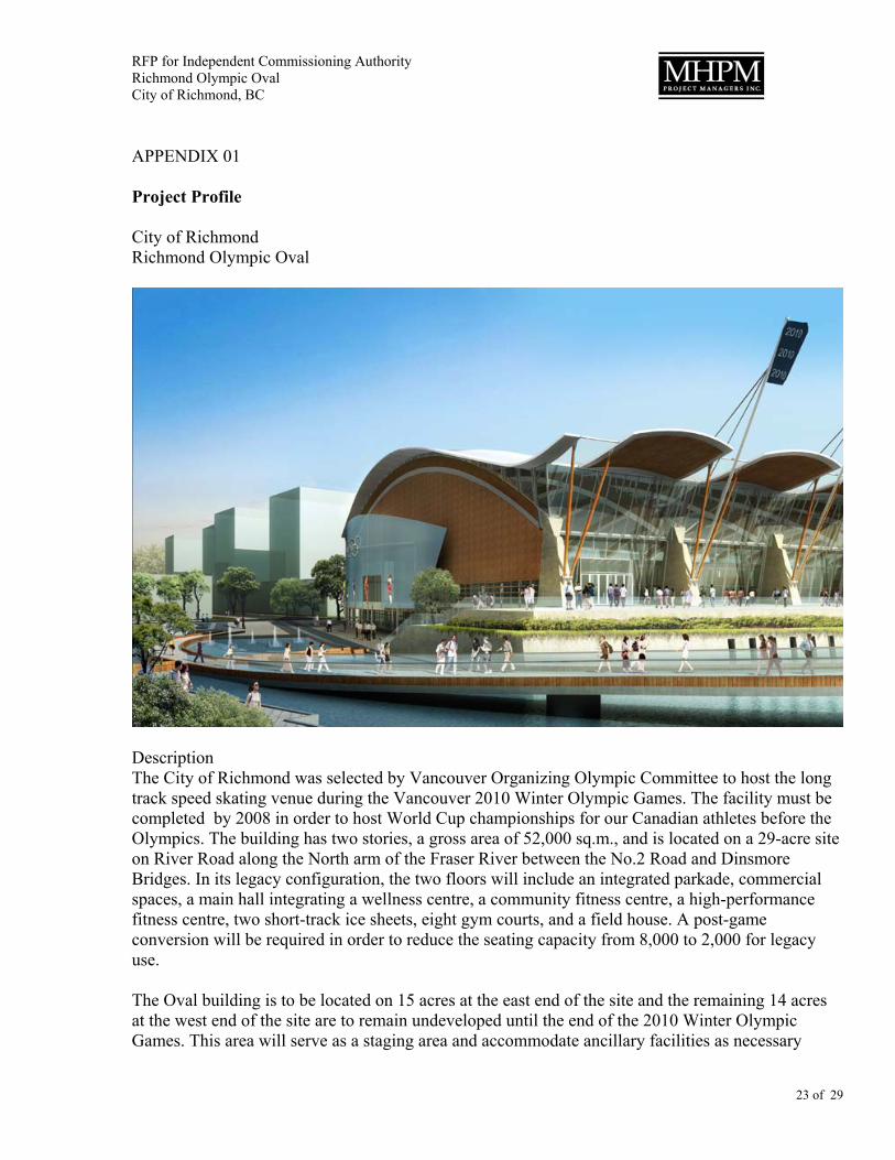
APPENDIX 01 Project Profile City of Richmond Richmond Olympic Oval
Description The City of Richmond was selected by Vancouver Organizing Olympic Committee to host the long track speed skating venue during the Vancouver 2010 Winter Olympic Games. The facility must be completed by 2008 in order to host World Cup championships for our Canadian athletes before the Olympics. The building has two stories, a gross area of 52,000 sq.m., and is located on a 29-acre site on River Road along the North arm of the Fraser River between the No.2 Road and Dinsmore Bridges. In its legacy configuration, the two floors will include an integrated parkade, commercial spaces, a main hall integrating a wellness centre, a community fitness centre, a high-performance fitness centre, two short-track ice sheets, eight gym courts, and a field house. A post-game conversion will be required in order to reduce the seating capacity from 8,000 to 2,000 for legacy use. The Oval building is to be located on 15 acres at the east end of the site and the remaining 14 acres at the west end of the site are to remain undeveloped until the end of the 2010 Winter Olympic Games. This area will serve as a staging area and accommodate ancillary facilities as necessary

RFP for Independent Commissioning Authority Richmond Olympic Oval City of Richmond, BC
24 of 29
during the Games. Upon completion of the Games, this area is to be redeveloped into a high-density residential community. The Oval building will be an iconic signature public building for the 2010 Winter Olympic Games with a clear span of 100 metres across the width and 200 across the length of the Oval. Designed and constructed to IOC, ISU and VANOC standards, it will be able to seat 8000 spectators during the Games and 2000 spectators post Games. The Oval is required to be a leading edge sustainable project, prominently feature BC wood or wood products, achieve a minimum of LEED® Silver certification and be programmed as a flexible world-class multi-purpose public facility post Games, convertible to festivals, events, concerts, and a variety of sports uses including being able to allow for ice floor and dry floor uses at the same time. The Waterfront Park portion of the project must be a premier urban riverfront and a key focus for downtown recreation and celebration both on the water and along the river’s edge. It will establish a pedestrian destination along the riverfront that encourages pedestrians and others to gather and linger and will include restaurant and other commercial activity within the Oval particularly post Games. A water feature is to be incorporated, as well as public art, cultural, and historic displays all forming a new waterfront edge. The total project budget is $178M. Commenced in July 2005, the site preparation works consist of clearing, densification, preload, and piling.

RFP for Independent Commissioning Authority Richmond Olympic Oval City of Richmond, BC
25 of 29
APPENDIX 02 Schematic Design Report (extracts on technical systems)

Mechanical Engineering
Introduction
Keen Engineering Co. Ltd. was commissioned by Cannon Design on behalf of the City ofRichmond to provide mechanical electrical and sustainable consulting for the design andconstruction of the Richmond Speed Skating Oval for the 2010 Winter Olympics.
This report was prepared for the use of the design team and the owner and is not intendedfor use beyond the conceptualisation of the proposed mechanical systems. The report isintended to convey our interpretation of the program and other information available to theteam at this time and to form a basis for final discussion on system types acceptable to theproject. The information in this report when approved by the client will form the basis ofthe project mechanical design.
It is noted that the project will be minimum LEED® Silver with the possibility of attainingLEED® Gold or better.
The mechanical designs and options will consider both the Olympic overlay and theLegacy requirements and will work to the more onerous condition were practical. If the aresignificant differences they will be noted for discussion and budgeting.
The project is anticipating the inclusion of a rowing tank for UBC and other items that arenot yet finalized.
6-1City of Richmond, Speed Skating Oval: Schematic Design Report

Mechanical General
Applicable Codes and Regulations
The mechanical, plumbing and fire protection systems shall be designed inaccordance with the intent of all applicable codes, ordinances and regulations. Thefollowing list of applicable codes and regulations apply to this design.
• 1998 British Columbia Plumbing• 1998 British Columbia Building Code• Model National Energy Code for Buildings• Provincial Fire Marshall Regulations• Fire Marshall Act• Applicable NFPA Regulations• Canadian Electrical Code• BC Refrigeration Code and CSA Codes governing Refrigeration Plants• BC Boiler and Pressure Vessel Act• Workers Compensation Board• Local By-Laws and Regulations
In addition to the above, the following standards shall be used in the design:
• ASHRAE(American Society of Heating, Refrigeration & Air Conditioning Engineers, Inc.)
• ASPE(American Society of Plumbing Engineers)
• SMACNA(Sheet Metal and Air Conditioning Contractors National Association)
Design Parameters
The heating, ventilation and air conditioning system (HVAC) for the project shall bebased on the following design parameters. The outdoor design conditions are takenfrom the BC Building Code 1998 for the City of Richmond:
Design Outdoor Conditions
(BC Building Code 1998) Summer 27°C db 19°C wbWinter -9°C db
Design Indoor Conditions
(ASHRAE Standards)
6-2 City of Richmond, Speed Skating Oval: Schematic Design Report

1. In lobbies and corridors adjacent to air conditioned spaces the areas will be air conditioned. In all others they will be ventilated and heated only.
2. In spaces without air conditioning the summer temperatures from outdoors willgovern.
The above values are a first cut and are subject to discussion and changes.
6-3City of Richmond, Speed Skating Oval: Schematic Design Report
Room Type A/C Summer Winter A/C Summer Winter
Oval Hall No 17 C 17 C Yes 17 C 17 C
Spectator Areas No 2 17 C Yes 21 C 21 C
Admin. Offices Yes 24 C 21 C Yes 21 C 21 C
Fitness & Training Yes 19 C 21 C
Hydro Therapy No 28 C 26 C
Physiotherapy Yes 22 C 21 C
Sport Science Yes 22 C 21 C
Hockey Change Rooms No 2 19 C
General Change Rooms No 2 22 C No 2 21 C
Rowing Tank
Lobbies & Corridors No1 2 21 C No1 2 21 C
Child Minding
Retail Yes 24 C 21 C
Athlete Lounge
Storage (Dry) No 2 20 C
Storage (Wet) No 2 20 C No 2 20 C
Mechanical Rooms No 2 18 C No 2 18 C
Electrical Rooms Yes 30 C 18 C Yes 30 C 18 C
Olympic Overlay Legacy Conditions

Relative Humidity
Acoustic Criteria
Background noise in the occupied space from any component of the HVAC systemsshall not exceed the values in the following table:
Space Maximum Noise Level Room Criteria (NC)
Oval Hall 40Spectator Areas 40Admin. Offices 35Fitness & Training 30Physiotherapy 30Sport Medicine 30Change Rooms 40Lobbies & Corridors 35Retail 35Storage 40
Mechanical system penetrations of acoustic separations shall not degrade theirspecified ratings.
Ventilation requirements
Ventilation rates will be based on ASHRAE standard 62.1 1999 and 2004 for this typeof facility. Rates vary from 4 l/s to 10 l/s minimum, depending on occupancy type. Inthe oval the ventilation rates will be based upon the total area of the ice or spectatorloads whichever is greater. The building will be designated as completely non-smoking.
Building Envelope Thermal Analysis
In general the facility should have an average R-20 walls and R-30 roof. The areabetween ice rinks and occupied space should be R-12. The roof and exterior wallsaround the spa area should be R-30.
6-4 City of Richmond, Speed Skating Oval: Schematic Design Report
Room Type Summer Winter Summer Winter
Oval Hall 40% *10% * 40%
Spectator Areas 40% 10% 40% - 60 % 40%
Olympic Overlay Legacy Conditions

Occupancy Schedules
In order to complete the operating energy model we will require a operating schedulefor the facility similar to the following:
Energy Sources
The project shall use electricity from BC Hydro for powering motors and controls.Natural gas shall be piped into the building to feed the boilers to provide domestic hotwater and to supplement the heating system. It is assumed that gas will be required forthe cooking appliances.
The option of geothermal energy will be reviewed to provide a heat source/sink for themechanical heating and cooling systems as well as capturing all energy used in the icemaking systems (refer to Appendix B).
Energy Target
The building will have an energy target of 40% reduction from ASHRAE Standard 90.1(MNECB). There are several strategies that will be considered to help achieve thistarget. These items will be listed in the sustainable measures section.
Plumbing Systems
General
All plumbing systems shall be in accordance with the BC Plumbing Code.
All water piping shall be insulated with fibreglass insulation with vapour barrier andidentified complete with flow arrows.
6-5City of Richmond, Speed Skating Oval: Schematic Design Report
S M T W T F S S M T W T F S
On
Off
On
Off
On
Off
On
Off
On
Off
On
Off
On
Off
On
Off
On
Off
On
Off
On
Off
Olympic Overlay Legacy Conditions
Room Type
Oval Hall
Spectator Areas
Admin. Offices
Fitness & Training
Retail
Storage (Dry)
Storage (Wet)
Physiotherapy
Sport Medicine
Change Rooms
Lobbies & Corridors

As-built record drawings and maintenance manuals for all plumbing systems andequipment shall be provided.
All water piping shall be copper type L with lead free soldered joints. All storm waterand sanitary piping shall be cast iron with mechanical joints. All sanitary vent pipingshall be cast iron complete with mechanical joints or copper DWV type. All isolationvalves shall be ball type.
All buried drain tile piping shall be SDR 28. Chlorinate all water systems. Pressure test all plumbing and fire piping systems.Provide seismic restraints on all piping and equipment.
Site Services
All site services will be brought to the building by the Civil Consultant (Delcan). Thefollowing are the requirements for the facility.
The building has the following approximate loads:
Building Plumbing Services
The mechanical room at the ground floor level shall house the following plumbingequipment.
• Water entry station• 150 mm double check valve assembly (domestic water)• Domestic water meter• Domestic hot water recirculation pumps and aqua-stat controls• Domestic hot water heaters and storage tank
The domestic hot, cold and recirculation water piping systems will leave the street levelmechanical room and be distributed through the ceiling space to serve fixtures on thedyke level and street level. In locations of future fit-outs, cap offs for all plumbing willbe provided in the individual spaces. Install a complete recirculation system formaintaining the water temperature on all domestic non-potable hot water pipes. Balltype isolation valves shall be provided on each branch or for group fixture isolation.
6-6 City of Richmond, Speed Skating Oval: Schematic Design Report
Size Load
Domestic Water & Fire ProtectionTwo 150 mm lines (6” each)
Dual Water Connection
Sanitary Sewer 200 mm (8”)
Storm SewerNo connection to City service

Hose bibs will be located around the perimeter of the building at approximately 50mon centre. There will be hose bibs in the parkade and in change areas for cleaning.Gray water collected from the roof of the facility will be used for flushing toilets andurinals. A storage and treatment system will provided for the rainwater.
All storm water will be collected on site (refer to civil report). The storm water will bepiped from area drains to the retention system and where required sumps and pumpswill be utilized for below the street level drainage. It is intended that whenever possibleall storm water will run by gravity to the retention system. The roof will be drained tograde through a number of downspouts and water features. There will be no interiorrain water leaders from the roof.
Sanitary will be piped by gravity to the service connection where possible. The streetlevel may have some areas requiring pump to make grade and in these isolatedlocation pumps will be utilized to lift the sewage to the required levels.
Refer to attached plumbing fixture cut sheets, for proposal fixtures.
Fire Protection Systems
The entire new facility will require a full Wet and Dry sprinkler system designed toNFPA-13 requirements. A new 200mm fire main will be required to service thesprinklers in the facility. With the size of the facility we anticipate that the floor areasfor parking and the Oval Hall will require multiple zones for the sprinkler systems.
Oval Hall 6 ZonesParking 4 Zones
The remaining areas of the facility will be zoned on a single zone per floor.Close spaced sprinklers or other specialty systems will be provided as required by thecode consultant as the design progresses.A new fire hydrant will be required on site to service a new Siamese connection at thefront of the Speed Skating Oval. The main entrance to the Facility is located on theSouth Side of the building.
Fire extinguisher cabinets complete with 4.5 Kg fire extinguisher will be providedthroughout the new facility at locations approved by the authority having jurisdiction.There is not a requirement within current codes for a standpipe and hose system forthe facility.
HVAC Systems
General
The systems will be designed to accommodate the legacy conditions now and in thefuture fit-outs of various spaces. The Central Plant will be sized to handle the fulllegacy conditions. Any Olympic Overlay requirements that are in addition to thelegacy conditions will be identified separately in this report.
6-7City of Richmond, Speed Skating Oval: Schematic Design Report

As-built record drawings and maintenance manuals for all HVAC systems andequipment shall be provided. Operator training will be provided for all mechanicalsystems.
Central Plant
It is intended to utilize all waste heat and spare cooling capacity of the Ice Plant toprovide all required cooling and most of the heating requirements. In addition to theheat recovery from the ice plant there will be two 750 kW high efficiency boilers toprovide the additional heating requirements. Heating water will be utilized for heatingthe building, heating the ventilation air and building domestic water.
The central plant will consist of distribution pumps, Heat exchangers from the iceplant, domestic hot water tanks and the boilers. All equipment will be set on 100mmhigh concrete housekeeping pads. The plant room will also contain the central controlsystems.
Distribution
Hot and chilled water will be distributed throughout the facility in the ceiling of thestreet level and piping will serve air handling units, fan coils and ancillary heatingdevices. All piping will be schedule 40 steel or copper and will be insulated andidentified.
All connections to equipment will have isolation valves, balancing valve, control valvesand unions for servicing. High points in the system will have air vents and low pointswill have drain points.
The entire distribution system will be sized for OIlympic overlay and full legacy use.Capped service will be provided in all future fit-out areas.
The heating and cooling system will be balanced, tested and commissioned.
Air Systems
Oval Hall:
The Oval Hall will be served by 3 air handling systems of an approximately 33,000 l/seach. The systems will be capable of 100% outdoor air system with a 50% heatrecovery from the exhaust air stream. The systems will be complete with pre-filters,heat recovery coil, 85% efficient bag filters, de-humidification coil/cooling coil, heatingcoil and supply fan.
Each system will have an axial return fan filter and heat recovery coil in the exhaustair stream.
The systems are arranged to provide one system for the legacy ice area and twosystems serving the remaining. The entire oval hall will operate at one temperatureand relative humidity when there is ice in the room.
6-8 City of Richmond, Speed Skating Oval: Schematic Design Report

Air distribution will follow the main structural systems and will have an integrateddesign strategy with the structure. The strategy will be to provide airflow to the spacewith a terminal velocity achieved at 2.0m above the ice surface.
It is proposed that the legacy de-humidification will be handled by the air handlingunits. The Olympic overlay loads in addition to the air handling capacities will bepicked up by rental desiccant de-humidifiers. The main differences in loads are theincrease in spectator capacities for the Olympic Games.
Ancillary Spaces:
The remaining spaces in the facility will be served by 2 air handling systems of anapproximately 7,800 l/s and 15,000 l/s each. The systems will be 100% outdoor airsystems with a heat recovery from the exhaust air stream. The systems will becomplete with pre-filters, heat recovery coil, 85% efficient bag filters, cooling coil,heating coil and variable speed supply fan. These systems will provide ventilation airand make-up air to the spaces.
Each system will have a centrifugal return fan filter and heat recovery coil in theexhaust air stream.
The perimeter zones of the facility will have 4 pipe fan-coils to eliminate the exteriorenvelope heating and cooling loads. These units will have 30% efficient filters and willonly run when required. The systems will be arranged typically for under floor airdistribution for the street level and dyke level areas. The Dyke level air supply will bein fixed lay-out while the street level will be in a raised floor plenum application
General and Washroom Exhaust:
All washrooms will be exhausted at a rate of 15 air changes per hour. Storage roomwill be exhausted at a rate between 2 air changes per hour and 12 air changes perhour depending on stored materials.The elevator machine room and electrical rooms will be exhausted to manage thetemperature of the space.
All washrooms will be exhausted through a centralized fan system complete with anair to air heat exchanger to pre-heat building make-up air. Localized exhaust systemwill be used for copier machines.
Parkade Exhaust:
The entire parkade will be exhausted by exhaust fans discharging to the outdoors.Fans will be provided to ensure the entire space is adequately exhausted. Whererequired transfer fans will be installed to move air in dead spaces inherent in the spacelay-out.
6-9City of Richmond, Speed Skating Oval: Schematic Design Report

Miscellaneous Heating Systems:
A radiant ceiling panel system will be used to provide exterior envelope heating for theLevel 1 change room.
Hot water unit heaters complete with DDC thermostats will be installed in at eachvestibule.
In various locations throughout the facility ancillary heating systems will be utilized toprotect opening etc. Entrance heaters will be provided at each entrance to the facility.Storage rooms, mechanical spaces, Zamboni space and stairwell will be heated byunit heaters and radiation.
In the child minding and yoga studio, in-floor radiant heat will be considered.
Controls
A Direct Digital Control (DDC) shall be provided. The controls system shall be a BacNetbased system. The system shall have a web based portal which will allow municipality staffto monitor the system remotely. The control system shall have full dynamic display andcharting capability.
All field control devices shall be electric with electronic controllers. The DDC system shallallow optimal utilization and energy efficient operation of the mechanical equipment.Computer graphic displays shall be provided for easy building operator interface withminimal training requirements. Electronic space temperature sensors shall be providedwith features which allow off-hours activation of mechanical equipment for specific floorsor zones as required by the users.
A comprehensive mechanical and control system commissioning program shall be used toensure operation of the systems in accordance with the design intent. The control systemshall incorporate energy metering to verify the energy uses in the building, for monitoringand verification purposes.
The DDC system will consists of several major sub-systems as follows:
• Direct digital control (D.D.C.) panels will be located at each major m e c h a n i c a lsystem (AHU, Boiler, Pumps).
• A central operator’s station including a C.P.U., CRT, keyboard and printer will belocated in the maintenance area.
6-10 City of Richmond, Speed Skating Oval: Schematic Design Report

Electrical Engineering
Introduction
This report is the schematic design summary of electrical systems planned for SpeedSkating Oval (RSO) of Richmond. It is primarily intended to indicate the basis of electricaldesign. These documents are preliminary in nature, and are only intended to be used asa guide, and to rely on past experience on similar projects to ensure a fully functionalelectrical installation. Documents of this division and drawings are diagrammatic and notto scale unless detailed otherwise. They establish scope, material and installation qualityand are not detailed installation instructions.
The description of the proposed electrical systems is based on architectural schematicdesign drawings. The material herein reflects Stantec’s best judgement in light of theinformation examined at the time of preparation. Any use a Third Party makes of thisreport, or any reliance on or decisions to be made based on it, are the responsibility of suchThird Parties. Keen accepts no responsibility for damages, if any, suffered by any ThirdParty as a result of decisions made or actions based on this report.
The building consists of speed skating oval and its support area, ice plant condenser room,Fan/Boiler room, two electrical rooms, Locker rooms, team rooms, Main floor parkade, sportmedicine and sport sciences facility, fitness area, administration, café and restaurant, etc.
The work shall include but not limited to the following:
• Complete normal and emergency power distribution system. (substation, emergencygenerator, and panel).
• Complete power supply, Motor Control Centers (MCC), starters, and disconnectswitches for all mechanical equipment.
• Complete indoor, outdoor lighting, and lighting control systems.• Complete sport lighting and control systems.• Complete power supply, starters, and disconnect switches for all equipment supplied
by others as required.• Complete life safety system (fire alarm, emergency lighting, and exit lighting).• Complete infrastructure for telecommunications, A/V, public announcement, and
security systems (cable trays and empty conduits).• Complete communications cabling system for voice and data systems.• Complete security system including cabling and devices.• Complete clock system.• Complete public announcement system.• For all the shell out areas, complete life safety systems, emergency light and exits
signs, panels and empty conduits to the electrical and communications rooms will beprovided for future tenant fit up.
• Commissioning, start up and training.
7-1City of Richmond, Speed Skating Oval: Schematic Design Report

General Electrical Provisions for Design
Conformance
The electrical and communications systems shall be designed in accordance with theintent of all applicable codes, ordinances, bylaws, standards and regulations.
The following list of applicable codes and regulations apply to this design:
• Fire Marshall, National Fire Code and Applicable NFPA Regulations• Canadian Electrical Code• BC Building code and local building by-laws• Worker’s Compensation Board and Canada Labor Code• EIA/TIA and CAN/CSA Standards of Canadian Standards Association• National Building Code of Canada• Underwriters’ Laboratories of Canada• Latest Edition of BICSI TDM Manual• VANOC guidelines and standards.
The following applicable standard of Richmond may apply to this design:
• City of Richmond Schedule “E” (Specification for Installation of Street Lights)
Scope
Complete, fully tested and operational electrical systems will be provided to meet therequirements described herein and in complete accordance with applicable codes andordinances, and good commercial installation practices.
Connection to equipment specified in other sections and to equipment supplied andinstalled by other contractors and/or by the owner will be provided including uncratingequipment, moving in place and installing completely; start-up and test.
Seismic restraints for all electrical equipment, and raceways will be provided.
All hardware, software, and firmware supplied under this contract will be confirmed tobe unaffected with date changes, leap years, and similar occurrences that plaguecomputer equipment.
Design Parameter
To obtain maximum performance of facilities, followings will be considered as theresult of venues and interviews with various oval facility managers, operators, andstaff with specific reference to building design and construction.
• Adequate power in the building and communications outlets throughout thebuilding.
• Floor boxes c/w power and communications outlets at many locations throughoutthe building.
7-2 City of Richmond, Speed Skating Oval: Schematic Design Report

• Consider lighting levels needed for TV broadcast.• Provide electric shades for windows installed for daylight.• Provide elevator for the access of disabled individuals.• Consider overhead data outlets.• Consider roof loading criteria in view of cable sizes and luminaries.
Sustainable Design
The design and operation of an energy efficient facility is important design goal. Dueto the favourable site constraints presented, it is anticipated that the energy relatedopportunities related to Daylighting would be achievable. Other environmentalperformance attributes of the project will be benchmarked against the LEED ratingsystem of the Canada Green Building Council by the design team.
Energy conservation, Environmental design issues and participation in EnergyEfficiency Certification programs include the following possibilities:
• LEED rating system of the Canada Green Building Council.• BC Hydro Power Smart Incentive Program.• Sustainable design will focus, but not limited, on the following;• Match system capacity to meet post-games loads and rent/purchase on-site
generator to provide back up for critical loads during the event.• Minimize up-lighting and maximize efficiency of exterior lighting systems.• Maximize the use of daylighting.• Consider the use of some renewable energy technologies, such as PV cells, wind
turbine and tidal energy generation, etc.
LEED Certification
The following are the potential LEED credits which are based on preliminary analysisof the project and will be further developed in later submission:
Sustainable Sites (SS) Credit 8 Light Pollution ReductionWe can obtain this point by meeting the light level specified by IESA. The luminairesthat are specified for the parking meet the glare reduction required by this point. Inaddition, we will avoid specification of any luminaire on the building with up lightcomponents.
Energy & Atmosphere (EA) Prerequisite 2 Minimum Energy PerformanceWe meet the ASHRAE/IESNA 90.1-1999.
Energy & Atmosphere (EA) Credit 1 Optimize Energy PerformanceThis will be part of the compliance with the ASHRAE/IESNA. We can obtain this creditif Client accepts the lighting level recommended by IESNA.
Indoor Environmental Quality (IEQ) Credit 8.1 Daylight & ViewsThe lighting will be coordinated with architectural light shelves and sky lights. Daylighting sensors will be installed to control the lights and shut off the lights in the areasexposed to day lighting.
7-3City of Richmond, Speed Skating Oval: Schematic Design Report

Load Estimate
An overall look at possible loading is as follows:
The chart includes a preliminary load estimate based on approximate areas on thearchitectural scheme and worst case scenario. The overall total is approximately 6,775with an estimated peak demand of 6,000KVA (Demand factor 90%). In addition to theabove calculation, we also use a second approach with detailed area break downwhich also provided total connected load very close to the above calculation. Thedetailed load calculation is in appendix A.
Materials
Materials and equipment installed shall be new, full weight and of quality specified.Same brand or manufacturer for each specified application shall be used.Each major component of equipment shall bear manufacturer’s name, address,catalog and serial number.
Standards of Materials, Equipment and Installation
Acceptable Products/Suppliers/Manufacturers are as followings:
Item Acceptable Products/Suppliers/Manufacturers
Power Distribution System Cutler Hammer, Schneider Canada, GE or approved equal
Battery operated emergency lights Ready Lite, Emergi Lite or approved equal
Luminaires Lithonia, Ledalite, Peerless, Architectural Lighting,Bega, Lightolier, Sterner sport lighting or approved equal
Fire Alarm Systems Edwards, Simplex, Notifier or approved equal
Outlets Bryant, Hubbel or approved equal
UPS GE, MGE, Powerware/Eaton, Liebert, APC or approved equal
Harmonic Mitigation
7-4
Area
Description SF W/SF KW W/SF KW W/SF KW W/SF KW
General 300,000 2.5 750 2.0 600 6.0 1800 2.0 600
Site Ltg. 25
Ice Plant 2500
Restaurant 400
Brick Pump Station 100
Total 300,000 2.5 775 2.0 600 6.0 4,300 2.0 1,100
Total Connected Load 625 + 600 + 4,300 + 1,100 = 6,775 KW
Pump, etc.Lighting Power Mech
City of Richmond, Speed Skating Oval: Schematic Design Report

Transformers Mirus Harmony 1, Powerware HRT, Delta Platinum or approved equal
Sound System Radium, Logical Solutions or approved equal
Structured cabling system Belden/CDT, Comscope, Amp Netconnect or approved equal
Electronic metering system Quadlogic or approved equal
Equipment shall be provided from the specified manufacturers.
Equipment on alternate & approved manufacturers list must be equal in quality andperformance to the model specified.
Electrical Services
BC Hydro Service
Point of service connection from BC Hydro to the building will be in the south westcorner of the development. From Two(2) BC Hydro substations – the RIM at GranvilleStreet and the SEA across the river, BC Hydro will bring two feeders to a switchingcubicle located on south west side of the Oval property. This feeders and the switchingcubicle will be installed by BC Hydro. From this switching cubicle, power feeder withmaximum demand of 6,000KVA @ 12.47/25 KV will be provided to the main electricalroom. BC Hydro request a 10 meter by 4.5 meter right of way for mounting itsswitching cubicle on south west side of the building. From this switching cubicle, theservice cable shall be terminated at the switchgear located in the Main ElectricalRoom. Refer to Appendix B for a picture of typical BC Hydro switching cubicle.
The medium voltage switchgear inside the main electrical room (West) shall consist ofthe following:
• Hydro cable termination,• Main switch,• Metering,• Three 15/25 KV transformer switches• One 2000 KVA ANN/ANF transformer c/w fan cooling capabilities• One 3200 A, 600/347 Volt, 4 Wire distribution center.
In addition, a 2nd electrical room will be provided close to the Ice plant with two 15/25KV load breaks and two 2000 KVA ANN/ANF transformers c/w fan cooling capabilityand two 3200A, 600/347Volt, 4 Wire distribution centers interlock to each other.
This service entrance configuration sketch is included in Appendix B.
All work will be carried out to meet BC Hydro standards. Concrete encasement will beprovided for the service ducts from property line to the pad mounted switching cubicleand from the pad mounted switching cubicle to the main electrical room and from themain electrical room to the 2nd electrical room beside the ice plant.
7-5City of Richmond, Speed Skating Oval: Schematic Design Report

Telus Service
Four (4) – 100 mm PVC ducts will run from Telus Manhole to the CommunicationsRoom. Pullboxes will be provided anytime more than 2 off-sets are installed. (Exactconnection point will be discussed and fixed with Telus representatives after the strikeis over.)
Cable TV service
Cable TV service shall be run underground from Telus manhole to theCommunications Room. A 100 mm PVC duct will be provided. (Exact connection pointwill be discussed and fixed with Telus representatives after the strike is over.)
Other Services
For other services such as connection to the VANOC temporary generators, Six (6) -100mm PVC empty ducts will be provided to main electrical room from a locationoutside of the building for VANOC to provide emergency power during the event forbroadcasting equipment. VANOC must provide information about the infrastructurerequired to distribute the power inside the building.
Power Distribution System
A complete power distribution system will be provided in Appendix B.
The underground ducts will connect the BC Hydro switching cubicle to the 15/25 KV MainSwitch in the main electrical room. BC Hydro metering will be provided as indicated. Inaddition provision for a certified electronic metering system will be included complete withall necessary hardware, firmware, and software to facilitate the on going measurement andmonitoring of the power consumption in the building.
The incoming 15/25 KV service shall be stepped down to secondary utilization voltage of347/600 Volts via 3 transformers as follows:
Transformer 1 Main electrical room (West)Transformer 2 &3 Ice Plant electrical room (East)
Transformers shall be dry type, three phase 2,000 kVA ANN/2,660 kVA ANF. One (1)transformer shall be installed in the Main Electrical Room, and two (2) in the Ice plantelectrical room. The secondary power distribution for the two transformers in the 2ndelectrical room shall be connected by Tie-breakers to provide redundancy in case one ofthe transformers failed. All transformers will have fan cooling capability with 3200A -347/600 Volt, 4 Wire secondary distribution center to provide additional power capacity atlower fault level.
Refer to Appendix B for the layout of Main Electrical Room (West) and Ice plant electricalroom (East).
7-6 City of Richmond, Speed Skating Oval: Schematic Design Report

The power will be distributed in the building at 3 phase 4wire 347/600V. This voltage willbe used to feed most of the mechanical equipment and any equipment that requires 3phase 600V for operation. The high intensity discharge (HID) lighting and fluorescentlighting will be at 347V.
120/208 Volts, 3 Phase, 4 wires power panels will be used for office equipment andconvenient outlets. The step-down transformers shall be installed in the local electric roomand to be minimum K13 rated.
Power and lighting panel boards fed from the main distribution center will be located atstrategic locations throughout the building.
All panelboards shall be 42 and 84 circuits complete with breakers as required.
In all the shell spaces, empty conduits will be provided. The Tenant will be responsible forinstalling the breaker in the main Electrical Room and wiring to the shell space. In addition,tenant will provide 600 Volt Panel, Transformers and 120/208 Volt panels and distributionof power insie the shell space.
All panelboard breakers shall be bolt-in molded case circuit breakers with thermalmagnetic trip, with trip-free action and trip position separate from the “On” or “Off” position.
All power distribution equipment shall be sprinkler proof.
All outlets, panel boards, transformers, distribution centres, etc. to be labeled withlamacoid labeling.
Power factor correction capacitors will be provided to keep the power factor between 91%to 95% lagging. The power factor capacitors will be installed on the line side of all themechanical equipment that is more than 15 hp.
Olympic Power Distribution System
All the Olympic power distribution will be provided by VANOC. This project will provideducts from each of the main and ice plant electrical room to a location outside of thebuilding for facilitating the connection to VANOC Generator during the event. VANOCmust provide information about the infrastructure required for distribution of its ownpower inside the building. In addition, the power are available in two electrical roomson east and west side of the building. VANOC will be responsible to distribute poweras required inside the building.
7-7City of Richmond, Speed Skating Oval: Schematic Design Report

Grounding and Lightning Protection
Grounding
All grounding and bonding shall be in accordance with applicable rules of theCanadian Electrical Code.
The water main and any metallic waste water pipe shall be bonded electrically to themain grounding system. The grounding conductor shall be the same size as requiredby the local electrical inspection authority. The UFER ground to be connected to atleast 6 columns on perimeter of the building located in different sections of the buildingconnected via #3/0 bare copper ground wire to the main building ground bus.
An isolated ground bus will be provided for the panels feeding the sound systems.Each ground bus will be connected directly to the main ground bus in the mainelectrical room via #3/0 insulated copper wire.
Separate ground wire will be installed in each conduit. The ground wire will be sizedbased on the largest wires installed in the conduit. The conduit shall not be used asground conductor.
Lightning Protection System
A lightning protection is not required but if required based on the insurance policy orother city’s concerns (City of Richmond required to make this decision), then thefollowing should be provided:
A lightning protection system consisting of air terminals, down-leaders, grounding rods,and bonding conductors as a minimum shall be provided as per all applicable codes.
The installation shall be coordinated with architectural elements to ensure that thesystem components are concealed and do not hinder the building aesthetics. Thelightning protection system may not be required if City of Richmond decides not tohave it. City of Richmond should review its policy about lightning protection for itsfacilities and instruct us if they require one.
Emergency Power System
Emergency Generator
The following loads shall be fed from the emergency distribution systems:
• Elevators,• Emergency mechanical loads,• Fire alarm system,• Emergency lighting,• Exit lighting,• Parking overhead doors, parking equipment,• Security systems,• Fire pumps,• Other life safety loads,• Other equipment required to be on emergency power as identified by the client
such UPS for data communications rooms, etc.
7-8 City of Richmond, Speed Skating Oval: Schematic Design Report

In addition to above client should prepare a list of the equipment which requiresemergency power.
The emergency power distribution system in the building consists of one (1) 300KW/375 KVA diesel generator which provides 347/600 Volt emergency power to thebuilding for life safety. Automatic transfer switches c/w a manual by pass switch willbe provided to automatically transfer the Hydro power to the emergency power systemif the utility power fails. Step down transformers will be used to provide 120/208 Voltfor some of the emergency power requirements in the building.
Refer to Appendix B for Generator Room layout. The final size of the generator will bedetermined by the number and capacity of loads required to be connected to theemergency system during the working drawing stage. The generators shall becomplete with residential quality mufflers, vibration isolators, daytanks, main tanks,and fuel transfer facilities. Factors such as refueling, engine exhaust and noise shallbe considered when selecting the location for the emergency generator.
The contacts which monitor the status of transfer switch and alarms from the generatorshould be connected to the Building Management System.
The emergency power is only for the building safety and VANOC shall provide its owngenerator power.
UPS Power Distribution System
A sufficient rating of UPS system will be provided for special systems such asadministration and data processing computers and facilities, with 20 minute batteryback-up. We estimate 10 KW UPS will be adequate for legacy use of the building.VANOC will provide the UPS required for the event. The UPS for the shell spaces willbe provided by the tenant.
All UPSs shall be fed from the emergency generator.
Wiring Systems
General
Wiring will be in accordance with the Canadian Electrical Code, and the City ofVancouver Electrical By-law.
The raceways for the project shall be as follows, unless required otherwise byauthorities having jurisdiction:
• Direct burial PVC Duct: For all duct banks.• Rigid Steel Conduit: In all areas where the wiring can be subject to damage.• Rigid PVC Conduit: In concrete or underground installation.• EMT: Use for general use, where allowed, unless otherwise stated in these
specifications, or on the drawings.• Flexible Liquid tight conduit: Provide a short length liquid-tight flexible conduit
prior to connection to each motor, transformers and generator.
7-9City of Richmond, Speed Skating Oval: Schematic Design Report

Wiring will generally have minimum #12 AWG of 1000V XLPE insulation and TECKcable or armored cable shall not be used. Armored cable is only allowed for drops toluminaires, and drops in partition walls.
Conduits and raceways will be concealed except in service spaces, ceiling spaces,and elevator, mechanical and electrical rooms.
Mechanical Wiring
Electrical service will be provided to all mechanical equipment, including but notlimited to air handling units, pumps, fans, heat tracing, chillers, air conditioners,cooling towers, heaters, boilers. This service will consist of the following:
• All protective devices for feeders/circuits feeding mechanical equipment, andMCCs, i.e. all circuit breakers, and fused switches,
• All conduit and wires,• Motor control centres (MCCs),• All starters, whether they are installed in MCCs, or loose in their own enclosures,• All disconnect switches.
MCCs will be installed in all mechanical rooms, and where mechanical equipment isinstalled. Loose mounted starters will be used only for isolated mechanicalequipment. MCC located at roof level will be weatherproof.
Wiring will be provided for the interconnection of MCCs, and fire alarm system.
Power correction capacitors will be equipped for all motors over 20 HP.
Where specified, controls equipment will be supplied and installed along with allnecessary conduit and wiring.
Heat trace cabling will be supplied and installed for all domestic water lines, and wetstandpipe system in the parkade, complete with all power connections, conduit, wire,and disconnect means as necessary.
Electrical Devices
The devices with specification grade will be used.All devices shall match, including and not limited to receptacles, and switches.
Extensive outdoor GFI power outlets will be provided to be utilized for civic functions,christmas lighting, seasonal lighting etc.
Minimum 2 duplex receptacles (one convenience and PC) per work station in officewill be provided, connected to different circuits (6 convenience receptacles to onecircuit, and maximum 3 PCs to a circuit).
7-10 City of Richmond, Speed Skating Oval: Schematic Design Report

Lighting System
A complete lighting system will be provided for all areas of the development in compliancewith codes, IES (Illuminating Engineering Society) recommendations, and clientrequirements. The supply, installation and connection of all interior and exterior lightingand related systems will be included.
The luminaires shall be suitable for the environment they are installed in, and suitable for thefunction of the space. The light sources shall be selected based on function of the space.
Lighting of RSO shall be considered as 3 categories - Oval Area Lighting, Structure Lightingand General Lighting – according to the characteristics of each lighting. Concept design ofthe Oval Area Lighting and Structure Lighting shall be by the Specialist Lighting Consultant.
Oval Area Lighting
The goal of the oval area lighting is to provide an appropriate and flexible lightingsystem with primary concern on the post Olympic (legacy) function of the Oval. Thelighting level and quality will be for recreational facility which will be between 30 to 70FC and the lighting quality will not be suitable for broadcasting. The lighting forOlympic will be supplied and installed by VANOC. VANOC must provide the architectand structural consultant with information about the infrastructure they require formounting and powering their luminaries. In addition, they require to provide us withinformation about how they want to distribute power inside the building so we canprovide them with infrastructure they require. We have allowed for the power availableinside the main electrical room and we assume that VANOC will distribute power fromthe main electrical room to its lighting panel and luminaries.
The lighting system will provide the IESNA (Illuminating Engineering Society of NorthAmerica) levels of horizontal and vertical footcandle levels, without exceedinguniformity requirements (Maximum to Minimum).
Energy consumption and maintenance issues will be considered in the selection oflight sources. Daylighting zones within the Oval will be considered in the design of theartificial lighting system.
Lamps will be chosen on the basis of accessibility, efficacy, and CRI (ColourRendering Index).
Basketball courts will be illuminated to a Class III (Club) level of 50 FC with auniformity ratio of 3.0 and a minimum Class IV (Recreational) level of 30 FC with auniformity ratio of 3.0.
Hockey Rinks will be illuminated to a Class III (Amateur) level of 75 FC (50 FCvertical) with a uniformity ratio of 3.0 and a minimum Class IV (Recreational) level of50 FC (25 FC vertical) with a uniformity ratio of 4.0. One of the two rinks will also havethe capability of being illuminated to 100 FC (75 FC vertical) with a uniformity of 3.0,for high performance play and possible television coverage.
7-11City of Richmond, Speed Skating Oval: Schematic Design Report

Track and field areas will be illuminated to a Class II (College) level of 50 FC with auniformity ratio of 2.0 and a minimum Class III (Competition) level of 30 FC with auniformity ratio of 2.5.
At this point in the design, high performance 1000 or 1500 watt floodlights are beingconsidered as the primary light source. The luminaires consist of a spun aluminumreflector with quartz glass coating providing excellent light control and better thannormal vertical footcandle levels.
In general, luminaires for Oval lighting will be installed on structural components of theOval. Provisions will be made for easy accessibility of the luminaire and sighting ofproper aiming angles.
Control of luminaires will be via a computerized multiplexed relay system that will allowcontrol of individual luminaires or groups of luminaires.
Power density at this time is estimated to be approximately 20 watts per square meter.For the Olympic event, we estimate the load will be at 40 watts per square meter. Thelighting for the Olympic will be supplied and installed by VANOC. The above loadestimate is only for the design of the HVAC system.
Structure and Landscape Lighting
The RSO shall have symbolic recognition as a monument of 2010 Olympic andParalympic Winter Games. The goal of structure lighting is to enhance the exteriorappearance of RSO, adding ambiance to the night scene. The structure lighting shallbe accomplished mainly by metal halide floodlighting or led fixtures with properaiming angle.
Building Functional Metal halide and compact fluorescent.
Building Flood Lighting Metal halide.
Building Decorative Metal halide, compact fluorescent or LED.
Building Iconic Wall and soffit mounted compact fluorescent or LED.
Landscape Functional Metal halide or LED.
Landscape Decorative Metal halide/compact fluorescent or LED.
General Lighting
Generally efficient sources will be used throughout including fluorescent, compactfluorescent with metal halide where appropriate. Some specialty rooms may includea minor amount of tungsten halogen track lighting and dimming. In general, thefollowing light sources and installation method will be utilized for particular areas:
7-12 City of Richmond, Speed Skating Oval: Schematic Design Report

Outdoor General Pole mounted architectural full cut-off luminaires with metal halide lamps.
Outdoor Parking Pole mounted architectural full cut-off luminaires with metal halide lamps.
Public square Recessed luminaires utilizing fluorescent and/or LED lamps.
Walkways Bollard lighting with refractors, utilizing metal halide lamps.
Walkways Wall mounted recessed walkway luminaire, utilizing metal halide lamps.
Indoor Parking Parking luminaire with high output fluorescent lamps.
Service Rooms Fluorescent strips.
Locker Rooms Vandal resistant, linear luminaires utilizing fluorescent lamps.
Hallway Recessed pot lights utilizing compact fluorescent, and/or MR-16 halogen lamps in the reception and service areas.
Community space Ceiling pendant mounted direct/indirect linear luminaires utilizing fluorescent lamps, fluorescent luminaires complete with acrylic lens, and two ballasts to allow independent switching, wall mounted decorative lights, and pot lights
Office areas Fluorescent luminaires complete with parabolic louvres, and two ballasts to allow independent switching.
Shell Space Fluorescent strips to meet the code for exit paths.
Refer to Appendix C, for some of the proposed luminaires.
All fluorescent luminaires shall utilize 3500K 85 CRI T-8 lamps, and electronic ballastswith less than 10% THD, and class A sound rating.
All HID luminaires shall be metal halide and shall come complete with HPF ballasts.
Lighting Control System
The lighting controls will be as follows:
• Low voltage control for all spaces and areas such as oval areas, structures,common areas and offices.
• Minimum one switch per enclosed space.• The enclosed offices will have three lamp luminaires with two switches. One
switch will control one lamp and the other one control the two lamps to providethree levels of lighting control.
• Multi level, multi switches for large rooms and spaces.• Conference rooms will be provided with dimmable switch for fluorescent
luminaries.• Switched wall lighting where pictures, renderings, murals, etc are displayed for
advertising, exhibition etc. purposes.• Occupancy sensors in lockers, washrooms and offices.
7-13City of Richmond, Speed Skating Oval: Schematic Design Report

• All exterior luminaires shall be controlled with PEC, time clocks, and BMS systemwith manual overrides.
• All low voltage lighting control will be connected to the Building ManagementSystem (BMS) which will be combined with the mechanical system and can beprogrammed to turn on and turn off the luminaires at specific time via the software
Daylight/Sun Control
Incorporation of controlled Daylighting as the preferable mode of lighting for alloccupied spaces will be considered to reduce lighting load and operating cost. Thissaves electricity and its associated peak demand charges which is the most expensiveform of energy.
The use of skylights on roof and/or light shelves on south facing facades will bringnatural light into interior space. Provisions of shading devices, such as overhangs orvertical fins, to let in quality natural light but exclude undesired direct sun light shouldbe considered.
Exit Lighting System
A complete exit lighting system will be provided to clearly indicate all egress routesfrom the facility, in accordance with the requirements of the building code and theLocal Fire Marshall.
The exit lights will be LED type and comply with the requirements of CAN/CSA-C860 standards.
All exit lights will be fed from the emergency power distribution system.
Emergency Lighting System
Emergency lighting to the lighting levels and requirements of applicable standards willbe provided in all public and egress routes throughout the building.
This system will consist of designated luminaires connected to the relevantemergency power distribution system, which will remain energized during poweroutage conditions.
Provide battery powered emergency lighting heads at main electrical rooms, generatorrooms, as required by codes. Battery units will be 1 hour rated except in generator andelectrical rooms, where they will be 2-hour rated.
Fire Alarm System
The fire alarm system shall be installed and verified in accordance with applicablestandards and requirements of CAN/ULC, treasury board and the local authority havingjurisdiction. The system shall be supplied and installed by an approved fire alarmequipment system installer in accordance with manufacturer’s requirements.The fire alarm system shall be a two-stage, multi-zone, supervised, graphic annunciatedaddressable fire alarm system. The system will be complete with manual pull stations,
7-14 City of Richmond, Speed Skating Oval: Schematic Design Report

automatic flame, smoke and heat detectors, sprinkler flow and tamper switches, andalarm notification such as visual and audible signals devices (bells, speakers and strobelights) as required.
The fire alarm graphic annunciator shall be located at the main entrance (firefighter’sentrance) to RSO and the main fire alarm panel to be located inside the maincommunications room.
Smoke detectors will be provided in all the electrical and communications rooms.
Beam type smoke detectors shall be installed in the Oval Area.
Fire alarm bells and combination audio/visual devices shall provide audible/visual signalsin accordance with the ULC requirements and local authority having jurisdiction.
All fire alarm wiring shall be run in conduit.
Operation of an alarm initiating device on first stage will cause the following to occur:
a. Indicate the zone activated at central control unit and on annunciator display.
b. Cause the alarm signal to sound throughout complex at 20 strokes per minutes.
c. De-activate all electric door hold devices and all fire doors or smoke control doors, ifnormally held open, to close automatically.
d. Transmit signal to the fire department via central station.
e. Shut down all mechanical supply and return air fans or to function to provide requiredcontrol of smoke movement.
Operation of an alarm initiating device on second stage will cause the system to go intoalarm and all the audible signaling devices to sound in alarm tone throughout building.
If first stage alarm is not acknowledged within 5 minutes, system to automatically go intosecond stage.
The system shall be monitored by base central monitoring agency as per CAN/ULCrequirements.
Provide batteries in the fire alarm system to ensure operation in the event of power outageas per codes.
The fire alarm zones will include the following:
• The sprinkler system zones, which will be electrically supervised in accordance with the building code, with zone sizes in accordance with NFPA 13.
• Each fire compartment required to be separated by vertical fire separations having afire-resistance rating of at least 2 hours.
• Each smoke zone as designed by the Architect and Mechanical Consultant.• Each shaft required to be equipped with fire detectors.• Each air handling system required to be equipped with smoke detectors.• Special zones will be designated in the Code consultant’s report.
7-15City of Richmond, Speed Skating Oval: Schematic Design Report

Telecommunications System
The communications infrastructure systems in the building shall be designed to the latestEIA/TIA and CAN/CSA Communications Standards and the latest issue of the BICSITDM manual.
Cable trays will be provided along outside perimeter of oval structure and in the ceiling ofadministration floor for routing of all the horizontal cables to the communications rooms.
All the horizontal outlets on each floor in the administration area to be terminated inside thecommunications room on the same floor. For each outlet, one 100 mm square boxcomplete with single gang mud ring and one 25 mm conduit to the ceiling space shall beprovided. If the cable trays are far from the outlets, then the 25 mm conduit from eachoutlet will be extended to the communications room on each floor.
Consolidation (zone) boxes will be provided in the communications room and all voiceand/or data horizontal cables to be 4 Pair, UTP, Category 6E. The cables to be terminatedon 8 pin modular jack (RJ45) at the communication outlet side and patch panel sidemounted on the rack inside the communications room. At each typical office workstation,minimum of three 4-pair, UTP, category 6E cable drops will be provided, two for data andone for voice.
Four data outlets on each floor ceiling will be provided for future wireless system.Payphone voice outlet will be provided in the hallway, lounge, and in exterior public square.
For the shell spaces, only empty conduits to the main communications room will beprovided. The communications cabling inside the shell spaces will be by tenants.A complete grounding system for the communications system, including a copper groundbus in communications room. Bond equipment racks, and cable trays to communicationground bus with #6 ground green wire.
The communications cabling system shall be warranted by the manufacturer of the cablingsystem for minimum of 25 years for performance of the system per communicationsstandards as specified.
Cable TV System
Complete cable TV infrastructure will be provided in the lounge, community space, andpublic square. The infrastructure shall consist of conduits, cable, outlets, and jacks. CableTV service will be provided on each level.
Cable TV outlets shall be located at the following locations:
• Administration,• Entrance Lobby• Inside of oval
Empty conduits only will be provided to shell spaces.
7-16 City of Richmond, Speed Skating Oval: Schematic Design Report

Audio/Visual Systems
Infrastructure for audio/visual systems, in the form of empty conduits, pull boxes, andpower supply shall be provided for the systems specified and provided by others. Theareas, where such equipment could be required, are as follows:
• Seminar/conference Rooms,• Locker Rooms• Inside the oval
Meeting with Audio/Visual consultants shall be held and the conduit system will be shownon detail drawings. Audio/visual in shell spaces will be provided by the tenants if required.
Public Address and Security Systems
Public Address System
A public address system consisting of speakers, amplifiers, microphone, console andinterface cards to the telephone system will be provided.
Security System
Infrastructure for security systems, in the form of empty conduits, pull boxes, and powersupply shall be provided for the systems specified and provided by others (securityconsultant). The areas, where such equipment could be required, are as follows:
• Door monitoring at all Space external doors,• Door monitoring at all access points to oval from parkade,• Card readers at selected external doors, and restricted internal access doors,• Motion detectors in the space and other common areas,• Glass break detectors in select areas.
Power to all security head-end equipment and CCTV cameras shall be provided.
Miscellaneous Systems
Electric service for the flowing will be provided:
• Provide power to overhead doors.• Power to garbage compactors.• Power to the elevators and all necessary electrical work for elevators, and elevator pits.• Power to all owner supplied equipment.• Power to window washing equipment.• Power to all automatic door openers and shades.• Electrical connections for all signages.• Extensive panic stations in the parkade.
7-17City of Richmond, Speed Skating Oval: Schematic Design Report

General Electrical Provisions for Construction
Laws, Notices, Permits and Fees
Contractor shall give all necessary notices, obtain all necessary permits and pay allfees in order that the work specified may be carried out, and furnish any certificatesnecessary as evidence that the work installed conforms with the law and regulationsof all authorities having jurisdiction.
All work shall be in accordance with the regulations, the codes in effect, and anyothers having jurisdiction as shown on, but not limited to, 2.1 Conformance.
Shop Drawings
Shop drawings shall be transmitted as indicated.
Shop drawings shall identify materials and equipment by manufacturer, trade nameand model number including copies of applicable brochure or catalog material.
Record Drawings
Record drawings identifying the location of all major pieces of electrical equipment andactual room names shall be provided.
The record drawings shall include, but not be limited to, the following changes andshall be recorded daily:
• Size, location, arrangement of all electrical equipment.• Routing of all underground conduit, ducts, and duct banks dimensioned from
landmarks on site.• Location of all outdoor installed electrical equipment, including but not limited to,
poles, landscape lighting, transformers, etc.• Location of all luminaries.• Circuiting.
Conduit Chases and Shafts
Unless otherwise indicated, contractor shall conceal all raceways in the constructionof the walls and ceilings, and in conduit chases, and shafts and furring. If it isnecessary, contractor shall consult the consultant for review before installation of thiswork and move the location of raceways from those indicated and provided.
Cutting and Patching
Holes and sleeves, cutting and fitting required for all electrical work shall be provided.Improperly located holes and sleeves shall be relocated.
Prior written approval from structural consultant before cutting or burning structuralmembers shall be obtained.
7-18 City of Richmond, Speed Skating Oval: Schematic Design Report

Support, Anchors, Seals & Firestopping
Provide all necessary supports, and hangers to secure electrical systems andequipment.
Provide firestopping at all electrical penetrations through rated floors/walls and shafts.
Provide shop drawings showing applicable assemblies. All products to be ULC listed.
Provide isolation and prevent contact with dissimilar metals.
All sleeves for electrical to extend 1” above the floor.
Vibration Isolation
Provide vibration isolation (spring isolators) on all large transformer and generator.
Seismic Requirements
Seismic restraints shall be provided for all electrical equipment, and attachment tostructural members in accordance with BC Building code.
The installation of seismic restrains shall not compromise vibration isolation capabilities.
Prior to construction commencement, contractor shall organize a meeting with thegeneral contractor, structural consultants and other appropriate parties. At that meeting,the contractor shall present in general the approaches/details used to provide seismicbracing for equipment, highlighting attachments to structure and trade coordination.
Contractor shall provide professional certification for all items installed. Seismicengineer is to provide letter of assurance Schedule C for all seismic components priorto building occupancy.
For t-bar ceiling luminaires minimum two wires shall be provided for attachment tostructure.
Painting and Identification
All exposed bare metal surfaces supplied by the electrical trade shall be cleaned byremoving all dirt, dust, grease and millscale.
All marred factory finished equipment, which is not scheduled to be repainted, shall berepainted to match the original factory finish.
Lamacoid labels shall be installed for all equipment for identification purposes.
7-19City of Richmond, Speed Skating Oval: Schematic Design Report

Equipment Protection and Clean-up
Equipment and material in storage on site and after installation shall be protected untilfinal acceptance. Special precautions shall be taken to prevent entry of foreignmaterial into working parts of electrical equipment.
All equipment of dirt, cuttings, and other foreign material shall be cleaned thoroughly.
Access Doors and Panels
Access panels shall be provided as required in building construction including inarchitectural walls and ceilings for access to any concealed electrical equipment which,in the consultant’s opinion, requires maintenance or adjustment. Access panel shallmatch wall/ceiling finish. Approval from architect shall be obtained prior to installation.
Access of Equipment
All arrangements shall be made in order to ensure that adequate access is availablefor all electrical equipment in accordance with all codes.
Performance Verification of Installed Equipment
Full sets of Operating and Maintenance Data shall be provided.
O & M manuals shall include the following:
• Name of engineer and electrical contractor and phone number.• Description of operation of all electrical systems.• Shop drawing of all equipment.• Extended warranties.• Maintenance and operation instructions.• List of manufacturer’s source and trade names.• Fire alarm verification certificate.• Copy of record drawings.• List of inspection and test certificates.
Testing
Contractor shall perform all testing required by the authority having jurisdiction, obtaintest certificates for all tests performed and include in operating manuals.
All tests shall be documented and witnessed by the consultant or general contractor.
Inspection
The consultant or their representative may choose to inspect all work prior to it beingconcealed.
7-20 City of Richmond, Speed Skating Oval: Schematic Design Report

The contractor shall notify the consultant in writing for the following minimum, but notlimited to, inspections (Required to provide a Schedule ‘C’ for occupancy):
• Below grade work prior to backfill.• All electrical rough-in prior to wall and ceiling finish installation.• Fire stopping of all electrical openings.• Pre-occupancy inspection.• Final occupancy inspection and verification of all equipment being fully
operational.• All work shall be approved by any other regulatory body having jurisdiction
where required.• The contractor is to provide copies of all permits, inspection reports and
certificates for insertion into the maintenance manual.• The contractor is to provide the consultant reasonable notice prior to calling an
inspection.• After the pre-occupancy inspection for substantial performance all deficiencies
shall be completed for the final inspection.
Commissioning, Demonstration and Instruction to Owner
Contractor shall demonstrate to and instruct the representative designated by theowner on the complete electrical systems operating and maintenance proceduresusing the assistance of specialist sub-trades and manufacturer’s representatives.
The following systems shall be demonstrated in regards to performance and safetyfeatures (to the fullest):
• Power Distribution System• Emergency Generator• Lighting control system• Fire Alarm System• Security System• Sound Systems• Communications System
Contractor shall obtain a signed statement from the owner certifying that thedemonstration and instructions have been given to his satisfaction.
As-built drawings and Operating and Maintenance Manuals shall be supplied,following commissioning.
Substantial Performance Inspection
Prior to requesting an inspection for substantial performance, contractor shall provideall the following items, to permit beneficial use by the owner.
• Comply with requirements in general contract conditions.• Submit maintenance and operating manuals.• Submit as-built drawings.• Submit fire alarm verification certificate• Instruct the owner’s operating personnel in accordance with the specifications.
7-21City of Richmond, Speed Skating Oval: Schematic Design Report

RFP for Independent Commissioning Authority Richmond Olympic Oval City of Richmond, BC
26 of 29
APPENDIX 03 Project Master Schedule

ID Task Name Duration1 Project Milestones 892 days
45 Programming 141 days
103 Site Master Planning 86 days
118 Environmental Assessment CEAA 162 days
133 Design 372 days
134 Schematic Design 169 days
167 Design Development 135 days
168 Preliminary Design Development 44 days
179 Design Packages 125 days
191 Progress Design Development 30 days
203 Final Design Development 30 days
217 Contract Documents 194 days
218 50% Contract Documents 65 days
233 Accelerated Tender Packages 140 days
250 95% Contract Documents 54 days
264 Procurement 497 days
265 Retain Construction Manager 301 days
294 Tender packages 376 days
295 Prepare Tender/Tender/Award TP#1 - Clearing and Grubbing 31 days
303 Prepare Tender/Tender/Award TP#2 - Densification 40 days
311 Prepare Tender/Tender/Award TP#3 - Preload 71 days
319 Tender and Award TP#4 - Piles 39 days
323 Tender and Award TP#5 - Cast in Place Concrete 31 days
327 Tender and Award TP#6 - Refrigeration Contract 17 days
331 Tender and Award TP#7 - Elevators Contract 31 days
335 Tender and Award TP #8 - Misc Embedded Metals 22 days
339 Tender and Award TP#9 - U/G Mechanical 31 days
343 Tender and Award TP#10 - U/G Electrical 31 days
347 Tender and Award TP#11 - Roof Structure 41 days
351 Tender and Award TP#12 - Mechanical 42 days
355 Tender and Award TP#13 - Electrical 42 days
359 Tender and Award TP#14 - Building Envelope 42 days
363 Tender and Award TP#15 - Interior Finishes 32 days
367 Tender and Award Landscape and Civil Works 27 days
371 Permits 124 days
380 Construction 966 days
381 River Road Relocation 326 days
382 Plan/Design/Tender 253 days
398 Construction 73 days
406 Site Preparation 310 days
407 Clearing and Grubbing Works 27 days
410 Soils Densification Works 71 days
413 Preload Works 263 days
419 Piles Works 116 days
422 Main Oval Building 644 days
423 Build Oval Cast in Place Concrete Works 476 days
427 Refrigeration Works 452 days
431 Elevator Works 522 days
435 Misc Embedded Metals Work 177 days
438 U/G Mechanical Works 179 days
441 U/G Electrical Works 179 days
444 Roof Structure Works 366 days
448 Mechanical Works 438 days
452 Electrical Works 421 days
456 Building Envelope Works 363 days
460 Interior Finishes Works 472 days
464 Landscape and Civil Works 249 days
467 Substantial Completion 0 days
468 Partial Occupancy 0 days
469 Commissioning 105 days
06/04 04/09
03/01 18/07
20/01 18/05
15/12 27/07
27/04 28/09
27/04 19/12
17/10 21/04
06/12 03/02
17/10 07/04
30/01 10/03
13/03 21/04
02/01 28/09
21/04 21/07
02/01 14/07
17/07 28/09
03/01 27/11
03/01 24/02
20/06 27/11
20/06 01/08
18/07 09/09
23/06 29/09
02/03 25/04
17/07 28/08
01/05 23/05
06/03 17/04
01/05 30/05
15/03 26/04
15/03 26/04
01/05 26/06
29/09 27/11
29/09 27/11
29/09 27/11
29/09 13/11
29/09 06/11
24/04 12/10
10/03 20/11
10/03 08/06
10/03 27/02
28/02 08/06
28/07 04/10
28/07 02/09
12/09 19/12
30/09 03/10
26/04 04/10
18/04 03/10
29/08 24/06
24/05 14/02
18/04 16/04
31/05 01/02
27/04 02/01
27/04 02/01
27/06 20/11
28/11 31/07
28/11 08/07
28/11 17/04
14/11 03/09
23/10 03/10
02/07 17/10
08/09
27/06 20/11
Nov Dec Jan Feb Mar Apr May Jun Jul Aug Sep Oct Nov Dec Jan Feb Mar Apr May Jun Jul Aug Sep Oct Nov Dec Jan Feb Mar Apr May Jun Jul Aug Sep Oct Nov Dec Jan Feb Mar Apr May Jun Jul Aug Sep Oct Nov Dec2005 2006 2007 2008
Critical
Critical Split
Critical Progress
Task
Split
Task Progress
Baseline
Baseline Split
Baseline Milestone
Milestone
Summary Progress
Summary
Project Summary
External Tasks
External Milestone
Deadline
Slack
Master Project ScheduleRichmond Speed Skating Oval
February 24, 2006
Project: 89087-9082(39)Issue Date: Feb 24, 2006
Progress Date: Feb 24, 2006
Page 1

RFP for Independent Commissioning Authority Richmond Olympic Oval City of Richmond, BC
27 of 29
APPENDIX 04 Stantec’s typical Commissioning specifications for Mechanical

NAME Section 15040 SCOPE COMMISSIONING Page 1 LOCATION
1. GENERAL
1.1 GENERAL REQUIREMENTS .1 Commissioning is the responsibility of this Mechanical Sub-Contractor. Provide the
services of a independent specialist firm to co-ordinate the commissioning of the equipment and systems specified under this Division and those items of other Divisions which interact with work of this Division as outlined herein, including the complete life safety and fire protection system.
.2 Provide all necessary trades to carry out the commissioning of systems as required.
.3 The Consultant shall, at his/her discretion, attend and advise in the commissioning process.
.4 Carry out additional tests as required to verify the proper operation of each piece of equipment and each system.
.5 Be responsible for the performance and commissioning of all equipment supplied under the Division 15 as well as the building fire protection and life safety systems (joint Division 15 and 16). Commissioning is static completion to full working order to specified requirements. It is the activation of the completed installation. The co-operation of all trades is essential for an efficient and planned process. A team comprising of the following is recommended: .1 Commissioning Co-ordinator .2 General Contractor .3 Prime Consultant .4 Design Authority (Division 15) .5 Building Owner .6 Division 15 Trades: especially controls including DDC; balancing agency .7 Division 16 Electrical .8 Division 17 Security Systems
.6 Submit a schedule and check list for the commissioning phase of the work. This schedule shall show: .1 Completion dates for each trade in each major section of the building. .2 Timing of the various phases of the commissioning, testing, balancing and
demonstration process. .3 Prepare a commissioning statement in which each of the four (4) phases that the
process is perceived to be worked through. In sequence, the phases are expected to be: • Phase 1 - System Readiness • Phase 2 - System Start-up, Testing, Balancing, etc. • Phase 3 - Verification of System Commissioning • Phase 4 - Demonstration and Instruction • Each Phase is applicable to each major and/or separate system making up
the work in Division 15 (plus Division 16 and 17 interface as applicable). .7 Personnel
Assign direct overall charge of commissioning to a person (the Commissioning Co-ordinator) fully qualified through practical experience and a comprehensive knowledge of the interactive nature of the building systems and their controls to understand the complete system and be available to carry the project through total completion. This person, a Principal or an employee of the Mechanical Sub-Contractor or hired from an outside source, shall be responsible for: commissioning, demonstration to the Owner, and certifications of substantial and total performance. Submit the name, address and phone number of the Commissioning Co-ordinator within two months of the award of the Contract.

NAME Section 15040 SCOPE COMMISSIONING Page 2 LOCATION
.8 Schedule Submit a schedule, as part of the construction schedules Section 01310, for the commissioning phase of the work. This schedule shall show: .1 Completion dates for each trade in each major section of the building. .2 Submission dates for the various documents required prior to substantial
performance. .3 Timing of the various phases of the commissioning. .4 The name and telephone numbers of the responsible person in each trade.
.9 Review Within four (4) months of commencing with the project work the person having direct overall charge of commissioning shall review design intent and intended commissioning three (3) months before Phase 1 (2) commissioning work on the project procedures with the Consultant. Six (6) months prior to the date of scheduled substantial performance submit a detailed plan identifying the orderly progression of the pre-start commissioning check and subsequent commissioning performance check of each sub-system leading up to the ultimate commissioning of entire systems.
.10 Laboratory Tests If the field tests indicate that equipment supplied to the project does not meet specifications, laboratory certification of the potentially deficient equipment may be requested by the Owner. In the event that equipment does not meet specifications, be responsible for the costs of: .1 the above laboratory test; and .2 all subsequent testing and correction required.
1.2 QUALITY ASSURANCE .1 The commissioning process shall be consistent with the "Code of Practice for
Commissioning Mechanical Systems in Buildings". .2 Within (20) twenty days of the award of the General Contract, supply the name,
qualifications, and experience of the commissioning co-ordinator for the review and approval of the Consultant.
.3 Acceptable Commissioning Firms: refer to Acceptable Products/ Suppliers/Manufacturers List, Reference 15010.
1.3 SCOPE All systems and equipment but not limited to the following: .1 Supply, return, exhaust and relief air systems. .2 Chilled water and condenser water systems with chillers, pumps and cooling tower. .3 Heating water systems with boilers, steam system, heat exchangers, heat recovery
chillers, and pumps. .4 Controls systems with calibration and sequence of operation in summer and winter. .5 Emergency systems including emergency generator operation, smoke removal, and
pressurization. .6 Pre-start up check out of all equipment and systems. .7 Start up of all equipment. .8 Check out operation of each system. .9 Document issues, resolutions, and results. .10 Plumbing systems. .11 Fire protection systems. .12 Seismic restraints

NAME Section 15040 SCOPE COMMISSIONING Page 3 LOCATION
2. PRODUCTS
2.1 SCHEDULES AND THE COMPLETION OF INSTALLATION OF SYSTEMS .1 Submit to the Consultants, 180 days prior to the scheduled Substantial Performance a
detailed and comprehensive installation completion/start-up/testing schedule including all Contractors and Suppliers involved. The schedule shall be updated and resubmitted for review, on a bi-weekly basis, during the course of commissioning. If found to be unacceptable, the Mechanical Sub-Contractor shall revise the schedule and the construction forces to suit the revised schedule. This schedule shall include but is not limited to the following items: .1 Mechanical Sub-Contractor - installation and piping testing of equipment and
piping systems. .2 Sheet Metal Contractor - installation and cleaning of duct systems and
equipment. .3 Chemical cleaning and treatment of piping. .4 Controls Contractor - control systems, inter-wiring, building automation system. .5 Air/Water Balancing Contractor and Maintenance Manual Agency. .6 Electrical Contractor - connection of electrical services to equipment specified
under this Mechanical Specification. .7 Equipment Suppliers for start-up of equipment. .8 Start-up for the various pieces of equipment & systems. .9 Testing of the operation of the components. .10 Trouble shooting. .11 Calibration of controls. .12 Prove out control software. .13 System and equipment check out sheet completion. .14 Demonstration of systems and equipment.
.2 At the time of the schedule submittal, also submit proposed testing recording sheets and procedures for review.
.3 Hold regular meetings during the commissioning process. Minutes of the meeting shall be issued to all contractors involved, the Consultant and the Owners representative.
2.2 DESIGN INTENT .1 Review with the Consultant the design intent of the project and the intended operation.
2.3 START-UP .1 Co-ordinate and supervise the start-up of the various pieces of equipment and systems.
Utilize the start-up services of the manufacturers representative. Ensure that the equipment is operating in a satisfactory manner. Check the following items: .1 Direction of rotation. .2 Grease and lubricants. .3 Noise. .4 Seals. .5 Alignment of pump and fan drives by a millwright. .6 Piping connections and safeties.
.2 Pre-start checklists and check sheets for all mechanical equipment shall be signed off by the Mechanical Sub-Contractor and counter signed by the commissioning agent. These checklists shall be made available to the Consultant for spot checking.

NAME Section 15040 SCOPE COMMISSIONING Page 4 LOCATION
2.4 TROUBLE SHOOTING .1 Resolve inter-contractor co-ordination problems. Where problems become apparent
during the commissioning process, work at the identification and resolution of these problems. The basic functions in trouble shooting are: .1 What - Identification and definition of the problem. .2 Why - Determination and evaluation of the causes. .3 When - Determine the time available to resolve the problem. .4 Involve the designing authority in the review of the problem and proposed
resolution. .5 Co-ordinate remedial action with the appropriate parties. .6 Evaluate the effectiveness of the remedial action.
2.5 OPERATION AND TESTING .1 Test the operation of the individual components and systems. Go through each step of
the sequence of operation and verify that each component operates correctly. Direct and ensure that all trades involved make the required changes and adjustments to affect the proper operation of all components and systems. Document the operations and sequences. See Commissioning tests.
.2 In conjunction with the Balancing Contractor document the performance of each component. Verify the operating point of equipment with respect to certified performance data. Review the results with suppliers.
.3 Test records sheets shall be reviewed by the Consultant prior to commencement of testing. The record sheets shall include a list of all specialist personnel, and specialized equipment required for the test to ensure that these are available on the testing date.
.4 Carry out operational tests for the current season and simulate operation of summer, winter and intermediate seasons.
2.6 DOCUMENTATION .1 Provide documentation of the commissioning process for inclusion into the maintenance
manuals. These are to include check out sheets, report forms, start-up certificates from Suppliers involved in start-up, documentation concerning demonstration to the Owner. Include all record and result sheets from tests specified herein.
.2 Maintain a daily log of key operating parameters, problems encountered, solutions employed and verification of effectiveness of solutions.
.3 Prepare detailed progress reports to coincide with regular commissioning meetings
.4 Refer to the fire protection and life safety systems commissioning schedules at the end of this section of the specification for minimum standard.
2.7 DEMONSTRATION .1 Organize and attend the demonstration to the Owner of all equipment and systems
supplied under this Division. The demonstrations shall occur only after the operation and testing has been successfully completed. Equipment suppliers shall participate in the demonstration as required.
.2 Refer to specification Section 15010.
2.8 HOLDBACK .1 Monies equal to 2% of the mechanical contract value will be held back for commissioning
and retained until the successful completion of commissioning.

NAME Section 15040 SCOPE COMMISSIONING Page 5 LOCATION
3. EXECUTION
3.1 PHASE I .1 Before starting any of the separate systems, provide a certificate stating that the specific
system is ready for start-up and the following conditions have been met. (See also Section 15900.)
.2 All safety controls installed and fully operational (dry run test).
.3 Qualified personnel available to operate the plant.
.4 Permanent electrical connections made to all equipment.
.5 System readings shall include, but not necessarily be limited to, the following:
.6 Checking system physical completion, including all instrumentation.
.7 Flushing, chemical cleaning (as required), charging, fluid treating (as required).
.8 Equipment lubrication and pre-start checks.
.9 Rotational checks.
.10 Air system cleaning complete.
.11 All DX systems checked for pressure and leakage.
.12 Filter systems installed and sealed in place.
.13 Adjusting vibration isolation and seismic restraints.
.14 Control function checks, including all alarms.
.15 Self-diagnostic packaged control items checked.
.16 All deficiencies to be recorded, reviewed by the commissioning team and, subsequently corrected before proceeding to the next phase, Phase 2.
3.2 PHASE 2 .1 System commissioning shall include, but not necessarily be limited to:
.1 Sub-system activation of all sub-systems.
.2 Sub-system testing and adjustment of all sub-systems.
.3 Major or composite system activation.
.4 Major or sub-system testing and adjustment. .2 As in the case of the System Readiness Phase, all deficiencies are to be recorded,
reviewed by the commissioning team and, subsequently, corrected. The process at the point of the deficiency shall be repeated before proceeding forward.
.3 Phase 2 is concluded when the installation is in full working order and acceptable for use. The work shall include the following: .1 Position all balance dampers in ductwork. .2 Position all balance valves in piping systems (where appropriate). .3 Make provision for testing air pressures and flow rates. .4 Set up air diffusers, registers and grilles. .5 Set up all automatic control valves/dampers and automatic temperature control
devices. .6 Set up constant volume and variable volume fans. .7 Adjust variable volume boxes and air valves as necessary. .8 Plug all air pressure and flow measuring holes. .9 Adjust vibration isolators and earthquake restraints as necessary.
.4 Fine Tuning .1 Setting up automatic controls for accurate response and precise sequencing. .2 Correction of problems revealed by balancing agency and change of fan speed
and pitch as necessary. .5 Testing
.1 A detailed check by a person having direct overall charge of commissioning. This check must include all items and functions to be later demonstrated to the Corporation's representatives.
.2 Systems operation in fire mode pressurization and smoke removal in the presence of the authorities having jurisdiction. Obtain a written statement/certificate of approval.

NAME Section 15040 SCOPE COMMISSIONING Page 6 LOCATION
3.3 PHASE 3 .1 Verification of Commissioning
Verification of commissioning by the Consultant shall not commence until the commissioning process Phase 2, has been totally completed. Submit test procedure completion test certificates at the time of requesting the commencement of the verification procedure. The verification process will include the demonstration of the following: .1 Location of an opening and closing of all access panels. .2 Operation of all automatic control dampers and automatic temperature control
devices. .3 Proper response of all variable volume air valves to thermostats and volume
adjustment controls. .4 Operation of all smoke removal provisions. .5 Operability of randomly selected fire dampers. .6 Noise level from typical variable volume air valves under extreme operating
conditions. .7 Operation of all equipment and systems, under each mode of operation,
including but not limited to the following: .1 DDC control features .2 Automatic controls including air compressors .3 Chiller and cooling tower .4 Packaged air conditioners .5 Special exhaust/make-up air systems .6 Packaged heat recovery system .7 Fuel oil pumps .8 Heat exchangers .9 Pumps .10 Cabinet unit heaters .11 Unit heaters .12 Fans .13 Coils .14 Tanks - expansion .15 Domestic water system .16 Fire protection systems
.2 At the completion of Phase 3 the Mechanical Sub-Contractor shall submit the following to the Consultant: .1 A letter certifying that all work specified under this contract is complete, clean
and operational in accordance with the specification and drawing. .2 A copy of Phase 2 verification certificates provided by the specialist trades for
transmission to the Corporation. .3 Record drawings as specified. .4 A letter from the testing and balancing agency certifying that all necessary data
for inclusion in operating and maintenance manuals has been received. .5 A statement confirming completion of BAS acceptance test, Section 15900.
.3 Upon receipt of all documents and a satisfactory outcome to the verification procedure, the Consultant will provide a certificate of verification for Phase 3.
.4 Substantial performance may, thereupon, be declared.

NAME Section 15040 SCOPE COMMISSIONING Page 7 LOCATION
3.4 PHASE 4 .1 Demonstration and acceptance shall not commence until the commissioning process
Phase 3 has been successfully completed - verification certificate issued and substantial performance declared. The demonstration process is a planned process requiring a pre-plan approval before commencement and a signed statement of satisfaction from the Corporation upon completion. Total performance will not be accomplished without this achievement.
3.5 COMMISSIONING TESTS Comprising of, but not limited to, the following: .1 Verify readings, calibration and set up, of sensors and equipment.
.1 Temperature sensors.
.2 Freeze protection.
.3 Flow switches, status switches, etc.
.4 Temperature and pressure gauges.
.5 Control damper tightness when closed.
.6 Alarm contacts. .2 Verify correct sensors are reporting accurately to the DDC panels and terminal. .3 Operate each of the air handling units. Verify and correct if required:
.1 Start/stop from the terminal.
.2 Correct start up/stop procedures with valves, dampers, etc.
.3 Verify stable operation of controls under normal conditions and with changes in air/water on/off conditions.
.4 Simulate operation at other seasonal conditions.
.5 Run trend logs to indicate operation.
.6 Piping, sensor, and unit installation.
.7 Check filters for bypass.
.8 All interfaces with DDC control system. .4 Operate each of the fan coil units. Verify and correct if required:
.1 Piping, controls, and unit installation.
.2 Operation of fan coil.
.3 Capacity of fan coil and appropriate water flow.
.4 Report on problems encountered if beyond the scope of this construction contract.
.5 This work may be carried out near or after substantial performance but to Owner completion times.
.5 Operate and verify each of the entry, stair, fan room etc. heating units.
.6 Operate and verify all systems, but not limited to: supply, toilet exhaust, general exhaust, kitchen exhaust, transformer room ventilation systems, smoke exhaust, generator room and ventilation, fume hood exhaust, parking supply and exhaust, and pressurization. .1 Start/stop from terminal or local device. .2 Damper operation. .3 Weather protection if appropriate. .4 All interfaces with DDC system.
.7 Verify proper operation of the heating water system. .1 Full check-out by manufacturer's start-up service representative. .2 Start/stop from DDC system. .3 All interfaces with DDC control system. .4 Pump start-up and interlocks. .5 Relief valves. .6 Verify that sensors are reporting accurately to the DDC panels and terminal. .7 Verify stable operation of the controls. .8 Expansion tank operation - check system procedures.

NAME Section 15040 SCOPE COMMISSIONING Page 8 LOCATION
.8 Verify proper operation of the domestic hot water system. .1 Full check out by Manufacturer's representative. .2 DDC control system interface. .3 Relief valve. .4 Recirculating pump operation. .5 Start and stop from DDC system.
.9 Verify operation of the steam system and specialities. .1 PRV stability over operating range. .2 Steam traps and vacuum breakers. .3 Control valve stability with changes in load and setpoint. .4 Relief valve. .5 Heat exchanger operation, capacity and flow rates.
.10 Verify operation of cooling tower, condenser water pumps, and support systems. .1 Cooling tower fan, dampers, condenser water control valves, make-up water,
bleed off and drain, and freeze protection on exterior piping and sump. .2 Condenser water pump and chiller control valves with sequence and flow rates. .3 Condenser water bypass. .4 Temperature control stability. .5 Start/stop from DDC system. .6 DDC control system interface.
.11 Verify operation of chillers, chilled water pumps, and support systems. .1 Full check out by Manufacturer's start up representative. .2 Full cooling, partial modes and heat recovery modes. .3 Single and parallel chiller operation. .4 Chilled water bypass. .5 Chiller capacities in heating and cooling modes. .6 Expansion tank operation - check system procedures. .7 Start/stop from DDC system. .8 DDC control system interface.
.12 Verify condition and systems pipe cleaning and chemical treatment for all systems.
.13 Verify duct cleaning, air and water balancing, and air pattern adjustments.
.14 Spray all roof and exterior wall penetrations with water and verify water tightness.
.15 Verify that all cooling coil drain pans operate.
.16 Verify backflow preventer operation.
.17 Verify operation of all plumbing fixtures, trap primers, etc.
.18 Verify operation of fire protection system. .1 Fire pump and jockey pump .2 Flow switches and tamper switches .3 Alarm .4 DDC control system interface
.19 Demonstrate access to all valves, equipment, components, etc. for servicing.
.20 Co-ordinate a power failure test with emergency generator start-up. .1 Fire pump start-up .2 Smoke/pressurization fan start-up .3 Misc. Equipment on emergency power .4 Fuel oil pump and level control/alarm operation .5 Stability of control equipment with start-up power surge .6 Stability of generator AC frequency i.e. 60 HZ ± 1.
.21 Verify sump pump operation, maintenance and alarm.
.22 Verify the operation of all equipment supplied and installed by this division.
.23 Verify hydronic heat pump units, pumps, boilers, heat exchangers, cooling towers, and make-up air units. .1 Heat pump operation for heating, cooling, air distribution, on/off/auto. .2 Operation and modulation of cooling tower. .3 Boiler operation and control. .4 Make-up air units.

NAME Section 15040 SCOPE COMMISSIONING Page 9 LOCATION
.5 Equipment performance. .24 Verify the seismic restraints of all required equipment, ductwork and piping.
3.6 BUILDING FIRE PROTECTION & LIFE SAFETY COMMISSIONING SCHEDULES .1 The following schedules are to be completed in addition to the required fire alarm
verification report and sprinkler system test certificates. .2 Substantial performance will not be considered completed unless the building fire
protection and life safety systems are fully commissioned without deficiencies.
3.7 POST-SUBSTANTIAL PERFORMANCE VISITS .1 Visit the site and the Owner's representative at 1 month and 6 months after substantial
performance for a minimum period of 2 days per site visit. .2 Review the operation of the systems. .3 Correct any operating problems. .4 Prepare a report for the Consultant and Owner for inclusion in the operating manuals of
the problems and issues that have arisen and the corrective action.

Section 15040 COMMISSIONING Page 10
FIRE ALARM INITIATION, SIGNALS AND ANNUNCIATION (1) Zone(s):
FIRE ALARM SIGNALS F.A. ALARM ANNUNCIATOR INITIATION MODE OF ALERT ALARM INDICATORS
TYPE CONDITION On Fire Floor
Entire Building
Special Areas
On Fire Floor
Entire Building
Special Areas
Alarm Indicator
Trouble Indicator
Misc. Indicator
Manual 1st stage
Pull 2nd stage Station Trouble
Area flow switch Area tamper switch
Sprinkler Special flow switch Special tamper switch Stand pipe tamper switch Flow switch Tamper switch
Main Low pressure Sprinkler Low sprinkler room temp.
Fire pump running Fire pump trouble (2) Elevator recall lobby Stairway
Smoke Duct Detector Area
Door holds and shutters Other
Heat Elevator shaft Detector Area
Other Generator Running
Trouble Mechanical Floor damper open/closed
Smoke System damper open/closed Control System fans running
Heat Trace Loss of power

Section 15040 COMMISSIONING Page 11
Monitor FIRE ALARM AUXILIARY ACTION SCHEDULE
AUXILIARY SYSTEMS & DEVICES SMOKE CONTROL & VENTING
INITIATION
DEVICE
Alternate Floor
Elevator Homing
Hold Open Devices Include. Shutters
(NFPA80)
Central Station Output Signal
Electro-Magnetic
Locks Released
Elevator Recalled
Pre-action Sprinkler Activated
Recirc. Air System Shut
Down
Dampers Press. Fans Activated
Smoke Exhaust Fans
Activated
Smoke Exhaust for
Atrium
Alert Signal
General Alarm
SPECIFIC FIRE ALARM DEVICE AUXILIARY ACTION SCHEDULE AUXILIARY SYSTEMS & DEVICES SMOKE CONTROL & VENTING
INITIATION
DEVICE
Alternate Floor
Elevator Homing
Hold Open Devices Include. Shutters
(NFPA80)
Central Station Output Signal
Electro-Magnetic
Locks Released
Elevator Recalled
Pre-action Sprinkler Activated
Recirc. Air System Shut
Down
Dampers Press. Fans Activated
Smoke Exhaust Fans
Activated
Smoke Exhaust for
Atrium
Manual Pull Station
Sprinkler Flow
Heat Detector
Smoke Detector
Duct Smoke Detector
Special Devices
Manual Switch at (1)
CACF

Section 15040 COMMISSIONING Page 12
FIRE ALARM VISUAL & AUDIBLE SIGNAL APPLIANCES (1) Zone(s):
SIGNALS/EQUIPMENT INDICATORS DEVICES Per Floor
(Number & Location) At CACF (Y/N) In Stair Shafts At Special Areas Trouble Other
Alert/Alarm Audible Signal Devices
(Indicate Type - i.e.: 10’ Gong)
Visual Signal Devices
Voice Communications
Fire-fighters Phone
Voice Communications
Paging

Section 15040 COMMISSIONING Page 13
FIRE ALARM SYSTEM MECHANICAL INTERFACE - MOTORS (List Motors & provide locations- indicate Action Upon Fire Alarm Initiation)
(1) Measure:
MOTOR
AUTO STOP
(on Signal from Fire Alarm System)
AUTO START OR FULL SPEED
(on Signal from Fire Alarm System)
(2) Electrical Supply
Protected From Fire
Manual Start/Stop Provided at CACF
Designation
Function
Location
Designation
Designation
Area of Building
Service by Equipment
On Specific Device
On General
Alarm
Special
On Specific Device
On Sprinkler
Flow
(Y/N)
(Y/N)

Section 15040 COMMISSIONING Page 14

Section 15040 COMMISSIONING Page 15
FIRE ALARM SYSTEM MECHANICAL INTERFACE - DAMPERS (List Motorized Dampers & provide locations- indicate Action Upon Fire Alarm Initiation)
(1) Measure:
DAMPER
NORMAL DAMPER
OPERATION
DAMPER POSITION ON
FIRE ALARM ACTIVATION
(2) Electrical Supply
Protected From Fire
Manual Start/Stop
Provided at CACF
Designation
Function
Location
Area of Building
Served by Equipment
Operates on
Mechanical Control System
Normal Damper Position (open/ closed)
On Fire Floor (open/ closed)
On Non-Fire Floor (open/
closed)
Other (open/
closed)
(Y/N)
(Y/N)

Section 15040 COMMISSIONING Page 16
EXPLANATORY NOTES FOR SCHEDULE 1 THROUGH 5
The shaded areas of the schedules would normally not be filled in. However, there may be circumstances that dictate otherwise. In these cases an explanation should be included.
These schedules are not intended to cover all equipment and operational sequences that may be incorporated in a design. Further information should be provided if these schedules do not accurately reflect the equipment and operation sequences employed.
NOTES:
Schedule 1
1. A separate sheet should be provided for each zone (or one sheet may be used for a number of identical zones).
Schedule 2
1. CACF represents the “Central Alarm Control Facility” per BC Building Code sentence 3.2.6.12.
Schedule 3
1. A separate sheet should be provided for each zone (or one sheet may be used for a number of identical zones).
Schedule 4 & 5
1. To be indicated if a specific “measure” for smoke control has been incorporated per BC Building Code sentence 3.2.6.
2. Details of the design to satisfy the requirement for protection from fire for electrical feeder to equipment should be provided.
END OF SECTION

RFP for Independent Commissioning Authority Richmond Olympic Oval City of Richmond, BC
28 of 29
APPENDIX 05 Stantec’s typical Commissioning specifications for Electrical
[Project Name] TESTING, ADJUSTING AND Section 16980 [Client or Owner] BALANCING OF ELECTRICAL Page 1 of 11 [Project Number] EQUIPMENT AND SYSTEMS Date
C:\Documents and Settings\gsavard\Local Settings\Temporary Internet Files\OLK5A\16980.DOC BS-Elec Masterspec\16980[Rev.02/04] 03/08/06 3:04 PM
1. GENERAL
1.1 Intent
.1 Except where otherwise specified, arrange and pay for testing, adjusting, balancing and related requirements specified herein.
.2 If test results do not conform with applicable requirements, repair, replace, adjust or balance equipment and systems. Repeat testing as necessary until acceptable results are achieved.
.3 Provide all labour, materials, instruments and equipment necessary to perform the tests specified.
.4 All tests shall be witnessed by persons designated by the Owner, who shall also sign the test documentation.
.5 Submit procedures proposed in writing for approval [two (2)] weeks prior to test.
1.2 Manufacturer's Production Test Records
.1 If requested, submit copies of production test records for production tests required by EEMAC and CSA standards for manufactured electrical equipment.
1.3 Site Testing Reports
.1 Log and tabulate test results on appropriate test report forms.
.2 Submit forms to [Consultant][Engineer] for approval prior to use.
.3 Submit completed test report forms as specified, immediately after tests are performed.
1.4 Reference Documents
.1 Perform tests in accordance with:
.1 The Contract Documents
.2 Requirements of authorities having jurisdiction
.3 Manufacturer's published instructions
.4 Applicable CSA, IEEE, IPCEA, EEMAC and ASTM standards
.2 If requirements of any of the foregoing conflict, notify [Consultant][Engineer] before proceeding with test and obtain clarification.
1.5 Manufacturer's Site Services
.1 Arrange and pay for the site services of approximately qualified manufacturer's representatives where site testing, adjusting, or balancing of electrical equipment or systems' performed by Manufacturer's representatives is:

[Project Name] TESTING, ADJUSTING AND Section 16980 [Client or Owner] BALANCING OF ELECTRICAL Page 2 of 11 [Project Number] EQUIPMENT AND SYSTEMS Date
C:\Documents and Settings\gsavard\Local Settings\Temporary Internet Files\OLK5A\16980.DOC BS-Elec Masterspec\16980[Rev.02/04] 03/08/06 3:04 PM
.1 Specified, or
.2 Otherwise required to ensure that electrical equipment and systems are operational in full compliance with the Contract Documents
1.6 Sequencing and Scheduling
.1 Except where otherwise specified, perform all testing, adjusting, balancing and related requirements specified herein prior to Interim Acceptance of the Work.
.2 Perform voltage testing and adjusting after user occupancy or utilization of facility.
2. PRODUCTS
2.1 Test Equipment
.1 Provide all equipment and tools necessary to perform testing, adjusting and balancing specified herein and as otherwise required.
3. EXECUTION
3.1 Fire Alarm System Testing - General
.1 [Consultant][Engineer] will be responsible for directing verification of fire alarm system installation in accordance with:
.1 CAN/ULC-S537, Standard for Verification of Fire Alarm System Installations, and
.2 Requirements of authority having jurisdiction.
.2 Contractor shall be responsible for:
.1 Performing prerequisites to verification procedure; and
.2 Assisting and cooperating with [Consultant][Engineer] in verification procedure
3.2 Fire Alarm System Testing - Prerequisites to Verification
.1 Prior to requesting verification by [Consultant][Engineer], do the following:
.1 Inspect system to ensure that the following items are completely installed, connected and fully operational in accordance with requirements of the Contract Documents and Manufacturer's recommendations:
.1 Complete fire alarm system including all components thereof
.2 All fire suppression and detection devices
.3 All smoke control equipment
.4 All other auxiliary equipment connected to fire alarm system

[Project Name] TESTING, ADJUSTING AND Section 16980 [Client or Owner] BALANCING OF ELECTRICAL Page 3 of 11 [Project Number] EQUIPMENT AND SYSTEMS Date
C:\Documents and Settings\gsavard\Local Settings\Temporary Internet Files\OLK5A\16980.DOC BS-Elec Masterspec\16980[Rev.02/04] 03/08/06 3:04 PM
.2 Ensure that any subsequent work remaining to be performed on the above-noted items will not invalidate examinations and tests performed during verification procedures.
.3 Ensure that operation and maintenance data has been submitted.
.4 Ensure that spare parts and maintenance materials have been delivered.
.2 Submit written request to [Consultant][Engineer] for verification, certifying that the above prerequisites have been fulfilled and specifying known exceptions in the form of a list of items to be completed, corrected or submitted.
.3 [Consultant][Engineer] will, within [two (2)] weeks after receipt of written request:
.1 Proceed with verification, or
.2 Advise contractor that prerequisites are not adequately fulfilled
3.3 Fire Alarm System Testing - Verification
.1 The contractor and manufacturer shall assist and cooperate with [Consultant][Engineer] in verification procedure. The contractor shall provide and pay for the following:
.1 Provide the following equipment:
.1 Voltmeter
.2 Sound pressure level meter
.3 Smoke generator or aerosol test smoke
.4 [Four (4)] portable communication devices
.5 Scaffolding and ladders
.2 Arrange and ensure that the following parties are present at all times during verification procedures:
.1 Electrical Subcontractor
.2 Fire alarm system manufacturer's representative
.3 Disassemble and reassemble system components
.4 Disconnect and reconnect wiring
.5 Perform required field adjustments
.6 Repair defective work and replace defective components
.7 Perform all work and tests on system required by verification procedure.
.2 Do not proceed with verification unless [Consultant][Engineer]'s representative responsible for directing verification procedure is present.

[Project Name] TESTING, ADJUSTING AND Section 16980 [Client or Owner] BALANCING OF ELECTRICAL Page 4 of 11 [Project Number] EQUIPMENT AND SYSTEMS Date
C:\Documents and Settings\gsavard\Local Settings\Temporary Internet Files\OLK5A\16980.DOC BS-Elec Masterspec\16980[Rev.02/04] 03/08/06 3:04 PM
3.4 Testing of Wiring and Wiring Devices
.1 All power and control wiring shall be tested for insulation resistance value with a 1000 volt megger. Resistance values shall be as recommended by cable manufacturer. Test results shall be properly tabulated, signed, dated and submitted with maintenance manuals.
.2 Test service grounding conductors for ground resistance.
.3 Test all wiring devices for correct operation.
.4 Test all receptacles for proper polarity and circuitry.
3.5 [Testing of wiring Devices in patient care area
.1 An acceptance test of the patient care wiring systems shall be performed by an independent professional testing agency. Submit to the [Consultant][Engineer] the name of the professional testing agency for approval prior to proceeding with the following tests.
.2 Should any failure to comply with the tests occur, alter or replace the wiring systems or devices with new, and retest to demonstrate compliance, all without extra costs to the [Consultant][Engineer].
.3 All tests shall be witnessed by persons designated by the [Consultant][Engineer].
.4 Consult with the [Consultant][Engineer] prior to preparing for any performing the tests specified. Submit procedures and test forms proposed in writing for approval.
.5 Receptacle Retentative-Force Test
.1 A force of 2.2N (8 oz) shall not remove a test pin from the ground slot of a receptacle in a patient care area.
.2 A force of 13.3N (3 lb) shall not remove a test attachment plug of the same configuration from a receptacles.
.3 Test each receptacle with a receptacle tension tester as manufactured by Daniel Woodhead Company.
.4 Any receptacles failing to comply with this requirements shall be removed from patient care areas and replaced. Non-complying receptacles shall not be utilized elsewhere on the project.
.6 Branch Circuit Impedance Test
.1 Refer to CAN3-Z32.2
.2 Perform the test specified
.3 Record the results on a separate form for each room.
[Project Name] TESTING, ADJUSTING AND Section 16980 [Client or Owner] BALANCING OF ELECTRICAL Page 5 of 11 [Project Number] EQUIPMENT AND SYSTEMS Date
C:\Documents and Settings\gsavard\Local Settings\Temporary Internet Files\OLK5A\16980.DOC BS-Elec Masterspec\16980[Rev.02/04] 03/08/06 3:04 PM
.7 Test of Ground Point Voltage Rise Under Fault Conditions
.1 Refer to CAN3-Z32.2
.2 Perform the test specified.
.8 Potential Difference Between Ground Points
.1 Refer to CAN3-Z32.2,
.2 Perform the test specified.
.9 Testing Report Documentation
.1 Upon completion of the CSA CAN3-Z32.2 testing, submit three copies of the testing report to the architect for approval.
.2 Each report shall contain:
.1 Table of Contents
.2 Description and Technical Data
.3 Copy of all Test Data
.4 List of Type and Accuracy of Testing Instruments Used.]
3.6 Ground Resistance Testing
.1 Measure ground resistance with earth test meter to verify compliance with CSA C22.2 No. 0.4 and Canadian Electrical Code.
3.7 Load Balance Testing
.1 Perform load tests when as many loads as possible, [prior to Interim Acceptance of the Work, are operable.]
.2 Turn on all possible loads.
.3 Test load balance on all feeders at distribution centres, motor control centre and panelboards.
.4 If load balance exceeds 15%, reconnect circuits to balance loads.
3.8 Power Factor Testing
.1 Record power factor readings at 15 minute intervals for full 24 hour period during normal operation of the facility.
.2 Take reading at following locations on distribution system:
.1 Main Service
.2 Motor Control Centre
.3 [ ]

[Project Name] TESTING, ADJUSTING AND Section 16980 [Client or Owner] BALANCING OF ELECTRICAL Page 6 of 11 [Project Number] EQUIPMENT AND SYSTEMS Date
C:\Documents and Settings\gsavard\Local Settings\Temporary Internet Files\OLK5A\16980.DOC BS-Elec Masterspec\16980[Rev.02/04] 03/08/06 3:04 PM
3.9 Voltage Testing and Adjusting
.1 Test voltage at all panelboards.
.2 Test voltage at all elevators.
.3 Test voltage at motor control centre.
.4 Adjust transformer tap settings to compensate for under-voltage or over-voltage conditions, if directed to do so by [Consultant][Engineer].
3.10 Testing of Transformer
.1 Each transformer shall be completely factory tested and the results certified, proving the performance of the units to provide capacities as listed in these specifications.
.2 Factory tests for each transformer to include:
.1 Resistance measurements of all windings
.2 Ratio test at rated connection and on all taps
.3 Polarity and phase relation tests
.4 Audible sound level tests
.5 No load loss at rated voltage and losses at 25%, 50%, 75% and 100% load
.6 Exciting current at rated voltage
.7 Laboratory test of insulating liquid
.8 Impedance
.9 Applied potential test
.10 Induced potential test
.11 95 kV B.I.L. test
.12 Hi-pot test
.13 heat run, temperature rise tests on each transformer.
The above heat run tests and impulse tests to be witnessed by the Owner.
.3 Notify the Owner [three (3)] weeks in advance, in writing, of the time, date and place of the tests. This test will be attended first by the Owner at the Owner's expense. Any subsequent witness tests due to any reason whatsoever shall be at the expense of the equipment manufacturer but at the direction of the Owner.
.4 Witness tests may be waived by the Owner at his discretion; such waiver shall be in writing and shall not imply any acceptance by the Owner nor limit the liability of the manufacturer. A copy of the test results is to accompany the transformers when shipped.
.5 Submittals
.1 Submit for review, shop drawings of all items specified in this section in accordance with "Shop Drawings" in the General Conditions.

[Project Name] TESTING, ADJUSTING AND Section 16980 [Client or Owner] BALANCING OF ELECTRICAL Page 7 of 11 [Project Number] EQUIPMENT AND SYSTEMS Date
C:\Documents and Settings\gsavard\Local Settings\Temporary Internet Files\OLK5A\16980.DOC BS-Elec Masterspec\16980[Rev.02/04] 03/08/06 3:04 PM
.2 At completion of work the prior to final acceptance, provide maintenance manuals for all items specified in this section.
.6 Site Testing
.1 After the transformers have been set in place, prior to energizing, verify in writing that the transformers have been installed and tested in accordance with recommended practice and are suitable for energizing and use. Without limiting the foregoing, the work shall, as a minimum, include the following:
.2 Prior to connecting, the Electrical Contractor is to inspect visually and conduct the following tests.
.1 Megger insulation and correct reading to 20-1/2 C base. Megger high voltage to ground with the secondary grounded for the duration of the test. Megger low voltage to ground with the primary grounded for the duration of the test.
.2 Perform electrical centres test on high voltage off-load tap changer switch.
.3 Sample transformer insulating liquid laboratory analysis to be carried out as follows:
.1 Dielectric breakdown
.2 Neutralization number
.3 Colour
.4 Interfacial tension
.5 Specific gravity
.4 Leak test piping.
.5 Perform ratio test for all transformer tap positions.
.6 Verify the shipping braces and shipping shims have been removed.
.3 After the connection of line, load, control and alarm wiring, but prior to energizing, the calibration and verification firm is to inspect the installation and confirm the following:
.1 That the transformer has been properly cleaned, is dry and free of foreign materials and contaminants and otherwise is suited for energizing.
.2 That all bus and connector bolts have been installed, tightened, torqued properly, and uninsulated surfaces of connectors and buses have been taped.
.3 That transformer taps have been set to provide the secondary voltage required.

[Project Name] TESTING, ADJUSTING AND Section 16980 [Client or Owner] BALANCING OF ELECTRICAL Page 8 of 11 [Project Number] EQUIPMENT AND SYSTEMS Date
C:\Documents and Settings\gsavard\Local Settings\Temporary Internet Files\OLK5A\16980.DOC BS-Elec Masterspec\16980[Rev.02/04] 03/08/06 3:04 PM
.4 That all insulators are imperfect condition, without cracks, chips or surface contaminants.
.5 That core, coil, terminal boards, tap changers, bushings and all insulated surfaces have not been damaged.
.6 That the forced cooling fans are functioning and that the power supply circuits to the fans have been properly connected and protected.
.7 That all alarm and indicating devices are operating correctly, are properly connected either internally and externally from the terminal of the instrument to the external system, including the following:
.8 Liquid level and pressure
.9 Liquid temperature, with hi and hi-hi contacts connected to the building control computer
.10 Sudden pressure relay is unblocked and wired to trip the primary circuit breaker
.4 Any other tests or inspections deemed necessary or appropriate by the manufacturer.
3.11 Miscellaneous Systems That Require Testing
SPEC NOTE: LIST AS REQUIRED
.1 [Electrical Clock and Program]
.2 [Building Entrance Control System]
.3 [Sound System]
.4 [Master Antenna Television System (MATV)]
.5 [ ]
3.12 Coordination and Short Circuit Study
.1 Provide a coordination/protective system study and short circuit study of all equipment specified herein and submit for review.
SPEC NOTE: ADD PRIMARY EQUIPMENT IF APPLICABLE
.1 Include the following:
.1 Utility overcurrent and fault protection devices

[Project Name] TESTING, ADJUSTING AND Section 16980 [Client or Owner] BALANCING OF ELECTRICAL Page 9 of 11 [Project Number] EQUIPMENT AND SYSTEMS Date
C:\Documents and Settings\gsavard\Local Settings\Temporary Internet Files\OLK5A\16980.DOC BS-Elec Masterspec\16980[Rev.02/04] 03/08/06 3:04 PM
.2 Primary switchgear
.3 Primary and 600v cable thermal damage curves
.4 600v air circuit breaker overcurrent, overload and ground fault devices
.5 347/600 and 120/208v panelboards, MCCs and switchgear, connecting feeder cables and bus duct
.6 15 kV and 600v transformer damage curves, magnetizing currents for all transformers 150 kVA and larger
.7 Locked rotor currents, acceleration times and damage curves for motors 75 kW and larger
.8 Any additional data necessary for successful completion of the coordination and short circuit study.
.2 Data shall clearly state the operating time in cycles of each breaker and indicate whether the time current curves for relays are inclusive of breaker tripping time or otherwise.
.3 Prepare a summation chart showing all ratings and settings with easy reference to the appropriate curve.
.4 Symmetrical and asymmetrical fault current calculations shall be submitted to verify the correct choice of the protective elements of the System.
.5 Prepare a systems single line diagram on which the resultant short circuit valves, device number and ratings are shown.
.2 Qualifications
.1 This study shall be provided by the suppliers of the 600V switchgear.
.2 This study shall be performed by and bear the stamp of the Professional Engineer registered in the Province of [Alberta.]
.3 Submittals
.1 Submit the complete study for review prior to carrying out calibration and verification.
.4 Tripping Devices
.1 Relay styles, CT ratios and fuse sizes have been selected on a preliminary basis for design purposes.
Final selection shall be based on the results of this study and shall be included at no extra cost.

[Project Name] TESTING, ADJUSTING AND Section 16980 [Client or Owner] BALANCING OF ELECTRICAL Page 10 of 11 [Project Number] EQUIPMENT AND SYSTEMS Date
C:\Documents and Settings\gsavard\Local Settings\Temporary Internet Files\OLK5A\16980.DOC BS-Elec Masterspec\16980[Rev.02/04] 03/08/06 3:04 PM
.5 Execution
.1 Provide the 600V switchgear supplier with all relevant data for equipment no provided by the supplier.
3.13 Calibration and Verification
.1 Description
.1 Calibrate and verify the following equipment items supplied under this contract:
.1 Primary switchgear
.2 15 kV 600V Oil Filled Transformers
.3 600V switchgear
.2 The calibration and Verification shall be carried out in the field after installation and connection of equipment, but prior to energization, in the presence of the Owner and the [Consultant][Engineer].
.3 Submittals
.1 Submit details of all test procedures and instruments, together with technicians names, to the [Consultant][Engineer], prior to proceeding.
.2 Submit written verification report after installation is completed to reflect as-built conditions.
.4 Qualification
.1 Work shall be performed by a firm specializing in and with relevant experience in testing 15 kV and 600V switchgear and protective relaying.
.2 This firm shall also perform the final checkout and testing of the equipment.
.5 Calibration and Verification
.1 The calibration and verification shall be carried out in the following stages:
.1 Primary switchgear
.2 15 kV pad mounted power transformer
.3 600v switchgear
.2 The Electrical Contractor shall advise well in advance when each stage is ready for the calibration and verification and he shall:
.1 Ensure that all equipment is installed, connected and cleaned inside and out.
.2 The electrical rooms are cleaned and are adequately illuminated and heated.
.3 Provide 120V convenience receptacles.

[Project Name] TESTING, ADJUSTING AND Section 16980 [Client or Owner] BALANCING OF ELECTRICAL Page 11 of 11 [Project Number] EQUIPMENT AND SYSTEMS Date
C:\Documents and Settings\gsavard\Local Settings\Temporary Internet Files\OLK5A\16980.DOC BS-Elec Masterspec\16980[Rev.02/04] 03/08/06 3:04 PM
.4 Provide one qualified electrician to assist in the calibration and verification.
.5 Provide all other facilities, equipment and personnel as reasonably required to assist in the calibration and verification.
.3 For each circuit breaker, calibrate all protective relays and overcurrent device time and instantaneous trips in accordance with requirements of the protected equipment and overall coordination scheme. Field set each relay according to the recommend settings.
.4 Verify all transformer ratios, insulation values, fuse sizes, C.T. and P.T. ratios, etc. and certify that the installation is in accordance with the requirements of the manufacturer and the Coordination/Short Circuit Study. Submit a written report on this verification to the [Consultant][Engineer].
.5 Carry out the tests required of calibration and verification firm as specified in the other related sections.
.6 Ensure all bus and cable connections are tightened to manufacturer's specifications.
.7 All relays are to be cleaned with dry, dust fee compressed air.
END OF SECTION

RFP for Independent Commissioning Authority Richmond Olympic Oval City of Richmond, BC
29 of 29
APPENDICES 6,7,8,9,10 Tables A to E

RFP for Independent Commissioning AuthorityRichmond Olympic OvalCity of Richmond, BC
Appendice 06 - Table ACommissioning Firm Experience (10 points)
Company Name: Contact Person:
Street Address:
City, State/Prov: Zip/Postal Code:
Telephone: Fax: Email:
Description of Business:
Commissioning Activities:Percentage of overall business devoted to commissioning services %
How long has the firm offered commissioning services? years
Average number of commissioning projects performed each year: projects
Number of registered engineers on staff who have directed commissioning projects engineers
List the Systems or Technologies for which your firm has provided commissioning :
Complete the following table showing relevant new construction project experience
List & Qualifications of proposed sub-consultants
1.
2.
Project Name & Reference
3.
4.
5.
Building Type(Office, hospitals, schools etc.) Systems or Technologies Involved
89087-9403(1)

RFP for Independent Commissioning AuthorityRichmond Olympic OvalCity of Richmond, BC
Appendix 09 - Table BCommissioning Personnel Experience (30 points)
Personnel name:Project name
1 2 3 4 5
3.2 Scope (see pages 10 to 19)in person-hours ( * )
3.2.1 Overview
3.2.2 Systems to be Commissioned
3.2.3 LEED® specific scope
3.2.4 Design Review
3.2.5 Technical criteria
3.2.6 Control System & Control Strategies
3.2.7 Operations and Maintenance (O&M)
3.2.8 Training
3.2.9 Commissioning Plans and Specifications
3.2.10 Construction Documents Review
3.2.11 Bid Phase
3.2.12 Construction Phase Review
3.2.13 Commissioning Report
3.2.14 Systems Manuals
3.2.15 Re-commissioning Management Manual
3.2.16 Post-Construction
Total person-hours per project/personnel
( * ) Attached detailed description 89087-9402(1)

RFP for Independent Commissioning AuthorityRichmond Olympic OvalCity of Richmond, BC
Appendix 08 - Table CApproach & Methodology
Approach to commissioning (10 points)
Approach to LEED:
Approach to comprehensive technical commissioning:
Understanding of the project issues, and requirements for a project of this nature:
Management & Administration (10 points)
Level of skills and experience:
Report Preparation:
Communication skills and presentation of ideas:
Team Work ability:
89087-9557

RFP for Independent Commissioning AuthorityRichmond Olympic OvalCity of Richmond, BC
Appendix 09 - Table DWork Plan (10 points)
Personnel: Management & Lead Other SubsSenior personnel C.A. personnel
1 2 3 4 5 6 7 8 TotalsInitials ( * ):
3.2 Scope (see pages 10 to 19)in person-hours
3.2.1 Overview
3.2.2 Systems to be Commissioned
3.2.3 LEED® specific scope
3.2.4 Design Review
3.2.5 Technical criteria
3.2.6 Control System & Control Strategies
3.2.7 Operations and Maintenance (O&M)
3.2.8 Training
3.2.9 Commissioning Plans and Specifications
3.2.10 Construction Documents Review
3.2.11 Bid Phase
3.2.12 Construction Phase Review
3.2.13 Commissioning Report
3.2.14 Systems Manuals
3.2.15 Re-commissioning Management Manual
3.2.16 Post-Construction
Grand total person-hours:( * ) Attached resumes
89087-9558

RFP for Independent Commissioning AuthorityRichmond Olympic OvalCity of Richmond, BC
Appendix 10 - Table ECost Proposal
in $ LEED (3.2.3) TECHNICAL TOTALSFixed Fee (30 points)
Detailed Scope (see pages 10 to 19)
3.2.4 to 3.2.8, 3.2.10
DESIGN/DRAWINGS STAGE
3.2.11 BID PHASEn.a.
3.2.12 CONSTRUCTION TASKS
3.2.3. f BEST PRACTICE COMMISSIONING (E&A credit #3) n.a.
3.2.9, 3.2.13 to 3.2.15
COMMISSIONING
3.2.16 POST-CONSTRUCTION
Totals
Reimbursable Expenses (for information only)
Upset Limit Allocationfor information only
Hourly Rates (for information only)
Name Position Hourly Rate
89087-9558

1783143
March 13, 2006 File: 02-0775-40-- INBOX/Vol 01
Finance & Corporate Services Fax: 604-276-4162 Admin. 604-276-4219 Accounts Receivable 604-276-4144 Payroll 604-276-4137 Purchasing 604-276-4270 Tax 604-276-4145 Treasury Services 604-276-4277
To All Potential Bidders on Request for Proposal 2759P - Independent Commissioning Authority for the Richmond Speed Skating Oval Re: Request for Proposal 2759P - Addendum 1 Although the attendance is not mandatory, please note (art. 4.6, p.21) that there will be a pre-proposal meeting on Tuesday, March 14 at 10 am at Richmond City Hall, in room 2.002. For further information, please contact Guillaume Savard, Arch. M.Eng. PMP, Project Manager for MHPM Project Managers Inc. You may contact Mr. Savard by fax 604-714-0989 or email [email protected] Yours truly,
Kerry Lynne Young Buyer KY:ky

City of Richmond Addendum #2 2759-P Request For Proposal – Independent Commissioning Authority Richmond Olympic Oval
1 of 1 89087
March 16, 2006 Addendum #2 2759-P – Independent Commissioning Authority Request For Proposal Richmond Olympic Oval (ROO) To All Potential Bidders on Request for Proposal 2759P – Independent Commissioning Authority for the Richmond Olympic Oval The following information provide clarification and confirmation of the requirements already stated in the RFP:
1) Art. 2.8: Last day for inquiry is Monday, March 20 at 2 pm. 2) Art. 2.9: Proponents are to check the website for the addenda. 3) Art. 2.16: A blank form is supplied by the City and the bidder’s insurer is to
completed it. 4) Art. 2.28: Peer reviewers are Trow (geotechnical), IBE (mechanical), RH.Strong
(refrigeration). 5) Art. 3.2.12: The listed tasks are explicit on the required reviews and site visits,
and do not imply duplication of field measurements with the trade contractors. 6) Art. 4.3.j: If the negotiation with the successful proponent goes well on Tuesday,
March 28, the CA will be asked to attend the IDP session on March 29. 7) Art. 4.8: There are 5 forms to fill and the bidder is entitled to 15 pages, excluding the
resumes. The bidder can use its own equivalent templates and use more than one sheet for a particular form.
8) Table B: For the five columns, the bidder can list 5 names under the same project, 5 projects with the same name, or a combination of the two.
9) Table B is similar to the Table D as it defines a work plan based on our scope of services (section 3.2). Table B is for past projects and Table D is for the Richmond Olympic Oval project.
10) Table E: Reimbursable Expenses as defined by item 15 below. The following Addendum modifies the requirements of the Request for Proposal 2759-P:
11) Article 2.15: The license is required indeed but only prior to commencement of work. 12) Article 3.2.3 f: After “independent peer review of the design”, add “, including the
Schematic Design Report and the Design Development Report” 13) Article 3.2.16.1: We may elect to require continuous rolling 2-year warranty. Include
cost for one review at Near Warranty End. 14) Article 4.5.j: After “all disbursements”, add “as defined at article 2.14” 15) Article 4.5.m: After “Reimbursable expenses”, add “(Manuals’ reprography and Out-
of-town Travel)”. Guillaume Savard, MHPM