Embed Size (px)
Citation preview

Request for Proposal:
Joint Strike Fighter for Australian Air Force
JLFANG Black Knight 170 Aerospace Engineering Design I
University of California, San Diego
Jacobs School of Engineering
March 19, 2003
Dr. James Lang, Project Advisor
Steven H. Christenson
Andrew S. Fischer
Ceazar C. Javellana III

Mission Requirements Design an unmanned, all-weather multi-mission aircraft Provide air defense, reconnaissance/surveillance and deliver
precision-guided tactical weapons at long range Capable of supersonic speeds for strike mission Minimize life-cycle cost with 12,000 hours service life Specific requirements:
Strike Mission:
Long range strike capability at speeds up to Mach 1.6 at or above 25,000 ft.
Capable of performing a 3-hour patrol at 25,000 ft.
2,000 lb payload capacity.
Limit load factor n=+6 and –3 fully loaded.
ISR/Attack Mission:
High endurance capability with range TBD.
Cruise for 8-hours at or above 25,000 ft at subsonic speeds.
2,000 lb payload capacity (ISR package or armament)
Unspecified limit load factor

JLFANG Black Knight 170JLFANG Black Knight 170

Black Knight 170 3-viewBlack Knight 170 3-view

Internal ComponentsInternal ComponentsAvionics – PurpleFlight & Propulsion Control System – OrangeFire Control System – GreenSystems and Equipment – BluePayload – Grey
Altitude
Distance
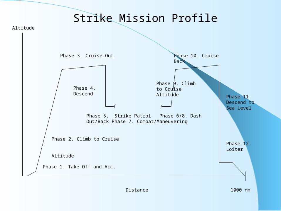
Phase 1. Take Off and Acc.
Phase 2. Climb to Cruise Altitude
Phase 3. Cruise Out
Phase 4. Descend
Phase 5. Strike Patrol Phase 6/8. Dash Out/Back Phase 7. Combat/Maneuvering
Phase 9. Climb to Cruise Altitude
Phase 10. Cruise Back
Phase 12. Loiter
1000 nm
Phase 11. Descend to Sea Level
Strike Mission Profile
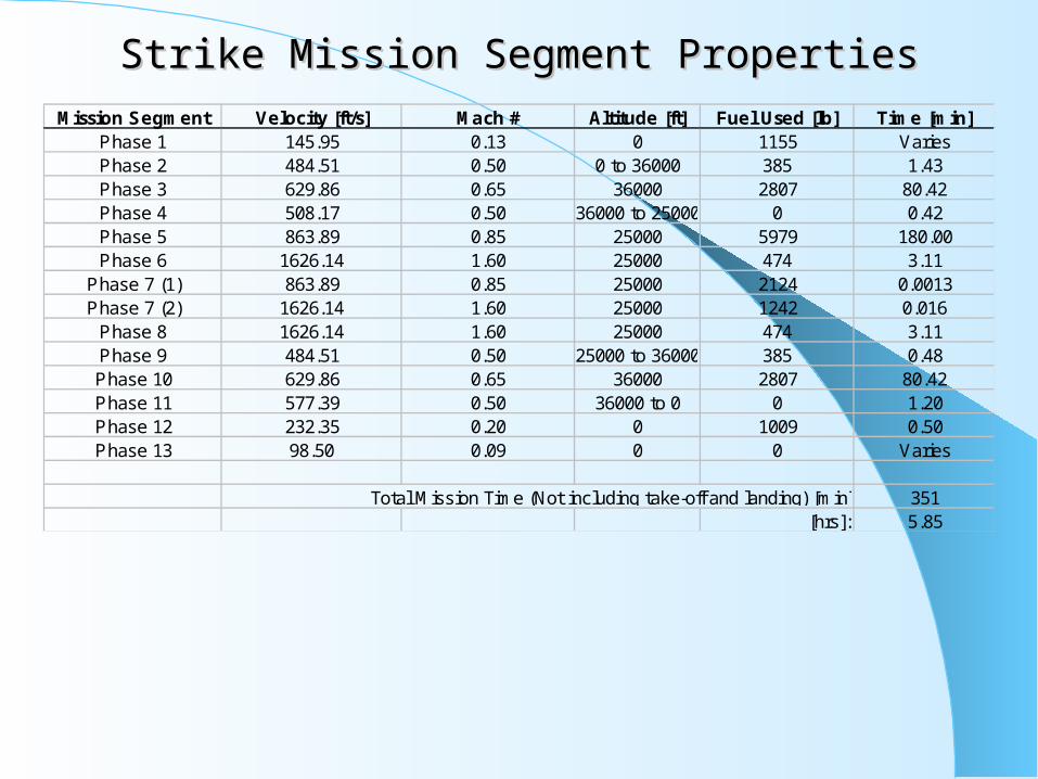
Strike Mission Segment PropertiesStrike Mission Segment PropertiesMission Segment Velocity [ft/s] Mach # Altitude [ft] Fuel Used [lb] Time [min]
Phase 1 145.95 0.13 0 1155 VariesPhase 2 484.51 0.50 0 to 36000 385 1.43Phase 3 629.86 0.65 36000 2807 80.42Phase 4 508.17 0.50 36000 to 25000 0 0.42Phase 5 863.89 0.85 25000 5979 180.00Phase 6 1626.14 1.60 25000 474 3.11
Phase 7 (1) 863.89 0.85 25000 2124 0.0013Phase 7 (2) 1626.14 1.60 25000 1242 0.016
Phase 8 1626.14 1.60 25000 474 3.11Phase 9 484.51 0.50 25000 to 36000 385 0.48Phase 10 629.86 0.65 36000 2807 80.42Phase 11 577.39 0.50 36000 to 0 0 1.20Phase 12 232.35 0.20 0 1009 0.50Phase 13 98.50 0.09 0 0 Varies
Total Mission Time (Not including take-off and landing) [min]: 351[hrs]: 5.85

Strike Mission Compliance SummaryStrike Mission Compliance Summary
Performance at Maneuver Thrust Req't Ps Req'd [ft/s] Comply Thrust Req'd [lb]1-g Specific Power Military 300 Meets 48661-g Specific Power Maximum 900 Meets 48665-g Specific Power Maximum 100 Meets 99185-g Specific Power Maximum 100 Meets 34477
Wing LoadingTake-Off [lb/ft^2] 49.34
Mid-Mission [lb/ft 2̂] 40.23Landing [lb/ft 2̂] 28.55
Thrust Required at Turning [lb] n=3, M=1.6 33526[lb] n=6, M=.85 12233
Take-Off DistanceT/W for 8000 ft Sto 0.039T/W for 5000 ft Sto 0.064T/W for 800 ft Sto 0.674
Max avail thrust at sea level [lb] 28800With T/W = .064, thrust req'd [lb] 2480With T/W = .674, thrust req'd [lb] 26020
Landing Distance[ft] 1362
Maximum Instantaneous Turn Rate Load Factor18 deg/s at M=.85, 25000 ft 8.5
12.6 deg/s at M=.85, 25000 ft 6.0
Weight SummaryWtake-off [lb] 38,500Wempty [lb] 21,420
Wfuel [lb] 15,080Wto/Wf 0.392
Wing Weight [lb] 5,478Wwing/Wto 0.142

Lift Curve Slope vs Mach Number
0
2
4
6
8
10
12
14
16
0.1 0.2 0.3 0.4 0.5 0.6 0.7 0.8 0.9 1 1.1 1.2 1.3 1.4 1.5 1.6
Mach Number
Cl a
lpha
(pe
r ra
dian
)
Calculated Cl alpha Theoretical Cl alpha
Strike Mission Aerodynamic PerformanceStrike Mission Aerodynamic Performance

Strike Mission Aerodynamic PerformanceStrike Mission Aerodynamic Performance
Drag Due to Lift vs Mach Number
0
0.05
0.1
0.15
0.2
0.25
0.3
0.1 0.2 0.3 0.4 0.5 0.6 0.7 0.8 0.9 1 1.1 1.2 1.3 1.4 1.5 1.6
Mach Number
Dra
g D
ue
to
Lif
t, K
Drag Due to Lift

Strike Mission Specific Excess Power 1-gStrike Mission Specific Excess Power 1-g

Strike Mission Specific Excess Power 5-gStrike Mission Specific Excess Power 5-g

Strike Mission Turn Rate at Sea LevelStrike Mission Turn Rate at Sea Level

Strike Mission Turn Rate at 25,000 ftStrike Mission Turn Rate at 25,000 ft

Strike Mission Sustained Load FactorStrike Mission Sustained Load Factor

Aircraft Characteristics - Srtike MissionAspect Ratio 6 Assumed in design
Wing Reference Area 780.3 ft 2̂ Calculated from Wing LoadingWing Span 68.42 ft Calculated from A = b 2̂ / S
Average Chord Length 11.4 ft Calculated from A = b / Cave(L/D)max 16 Estimation from Figure 5-6 with aspect ratio of 6
Wing Sweep 40 degrees Assumed in designWing Taper Ratio 0.5 Assumed in design
Airfoil 63A010 Table G.1Max Thickness 1.14 ft Calculated from %max thickness and chord length
LE Radius 1.09 in Figure G.1Moment Coef, Cmo 0.005 Table G.1
Airfoil Max Lift Coef. 1.20 Table G.1
Strike Mission Aircraft Characteristics Strike Mission Aircraft Characteristics
Fuselage DataAssume :Sears-Haack BodySmax = 6532 in 2̂ = 544 ft 2̂Arcraft Length = 454 in = 37.8 ft
1010.90 Fuselage Volume [ft 3̂]365.06 Fuselage Wetted Area [ft^2]0.448 Cdw Aircraft Wetted Area
1948.20 [ft 2̂]
Control Surface Sizing
Chord (ave) [ft] Span [ft]Aileron 2.3 13.7
20% of Wing Chord 40% of Wing Length
Flaps 3.4 13.730% of Wing Chord 40% of Wing Length
Stability and Control
Closed loop automated flight control system augmented with thrust vectoring

Strike Mission Engine DataStrike Mission Engine Data
Engine Dimensions (scaled)Length [in] 304
Diameter [in] 45.6Compressor Face Diameter [in] 64
F-100 Turbofan Engine Data Sea LevelMax Thrust [lb] Max Thrust [lb] Max Thrust [lb] Max Thrust [lb] Max Thrust [lb]
Installed Thrust w/ Afterburner Static M=.85 M=1.6 M=.85 M=1.6Scale 1.6 28800 22400 34880 17600 27200
Engine Weight [lb] 4379Scale 1.00 18000 14000 21800 11000 8800
Engine Weight [lb] 2737TSFC [lb/lb-hr] 2.48 2.20 2.38 2.17 2.22
25000 ft 36000 ft

Strike Mission SummaryStrike Mission Summary
Meets mission requirements (except one *)
-550 nautical mile mission radius
-Ps at prescribed alt, Mach and load factor
-Take-off distance < 800 ft capable
-Turn rate 12.6 deg/sec at 6-g’s *
38,500 lb take-off weight, 21,420 lb empty weight
Fuselage 37.8 ft long, 68.4 ft wing span, Sref 780 ft^2
130 x 20 x 20 inch payload bay – (8) 250 lb Mk-81 bombs or (1) 2,000 lb JDAM Mk-84 bomb
Scaled F-100 engine delivers 28800 lb static thrust
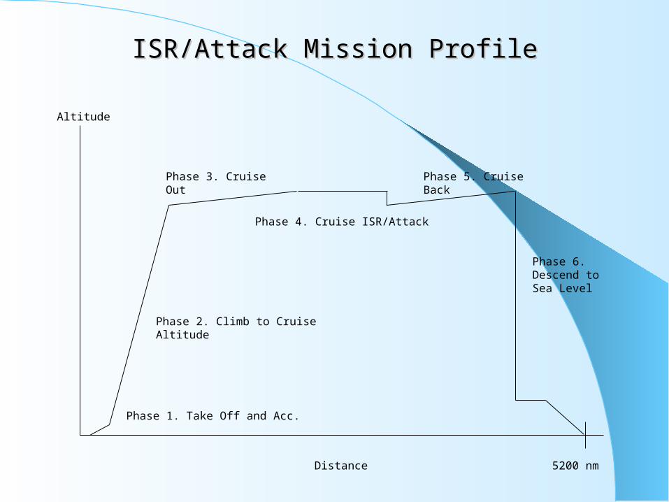
Altitude
Distance
Phase 1. Take Off and Acc.
Phase 2. Climb to Cruise Altitude
Phase 3. Cruise Out Phase 5. Cruise Back
5200 nm
Phase 6. Descend to Sea Level
Phase 4. Cruise ISR/Attack
ISR/Attack Mission ProfileISR/Attack Mission Profile

ISR/Attack Mission Segment PropertiesISR/Attack Mission Segment Properties
Mission Segment Velocity [ft/s] Mach # Altitude [ft] Fuel Used [lb] Duration [s]Phase 1 216.26 0.19 0 641.44 variesPhase 2 577.39 0.50 0 to 35000 213.81 121Phase 3 681.17 0.70 35000 2920.35 23192Phase 4 681.17 0.70 35000 2978.26 28800Phase 5 681.17 0.70 35000 774.68 3968Phase 6 681.17 0.70 35000 2920.35 23192Phase 7 681.17 0.70 35000 to 0 0.00 103Phase 8 681.17 0.70 0 227.86 1800Phase 9 312.41 0.27 0 0.00 varies
Total mission time (Not including take-off and landing) [min]: 1352.93 [hr]: 22.55

ISR/Attack Mission Compliance SummaryISR/Attack Mission Compliance Summary
Wing LoadingTake-Off [lb/ft^2] 97.53
Mid-Mission [lb/ft 2̂] 79.52Landing [lb/ft 2̂] 56.44
Take-Off DistanceT/W for 8000 ft Sto 0.082T/W for 5000 ft Sto 0.136T/W for 3200 ft Sto 0.234
Max avail thrust at sea level [lb] 9200With T/W = .136, thrust req'd [lb] 5253With T/W = .234, thrust req'd [lb] 8993
Landing Distance[ft] 2303
Weight SummaryWtake-off [lb] 38,500Wempty [lb] 21,380
Wfuel [lb] 15,080Wto/Wf 0.392
Wing Weight [lb] 1,912Wwing/Wto 0.050
Thrust Required at Turning Conditions Thrust [lb]n=1.5, M=.7, 25000 ft 2041

ISR/Attack Mission Aerodynamic PerformanceISR/Attack Mission Aerodynamic Performance
Lift Curve Slope vs Mach Number
0
2
4
6
8
10
12
14
16
0.1 0.2 0.3 0.4 0.5 0.6 0.7 0.8 0.9 1
Mach Number
Cl a
lpha
(per
rad
ian)
Calculated Cl alpha Theoretical Cl alpha

ISR/Attack Mission Aerodynamic PerformanceISR/Attack Mission Aerodynamic Performance
Drag Due to Lift vs Mach Number
0
0.05
0.1
0.15
0.2
0.25
0.1 0.2 0.3 0.4 0.5 0.6 0.7 0.8 0.9 1
Mach Number
Dra
g D
ue to
Lift
, K
Drag Due to Lift

ISR/Attack Mission Aircraft CharacteristicsISR/Attack Mission Aircraft Characteristics
Stability and Control
Closed loop automated flight control system augmented with thrust vectoring
Fuselage DataAssume :Sears-Haack BodySmax = 6532 in 2̂ = 544 ft 2̂Arcraft Length = 454 in = 37.8 ft
1010.90 Fuselage Volume [ft 3̂]365.06 Fuselage Wetted Area [ft^2]0.448 Cdw
Control Surface Sizing
Chord (ave) [ft]Span [ft]Aileron 1.1 14.9
20% of Wing Chord40% of Wing Length
Flaps 1.6 14.930% of Wing Chord40% of Wing Length
Aspect Ratio 14Wing Reference Area 394.74 ft 2̂
Wing Span 74.34 ftAverage Chord Length 5.31 ft
(L/D)max 28Wing Sweep 0 degrees
Wing Taper Ratio 0.52Airfoil 64 3-018 Table G.1
Max Thickness .956 ftLE Radius 1.27 in
Moment Coef, Cmo 0.004 Table G.1Airfoil Max Lift Coef. 1.5 Table G.1
Subsonic CdoCdo at M=.85 0.017
Figure G.1
Figure E-6
Aircraft Characteristics - ISR/Attack Mission
Extrapolation from Figure 5-6 with aspect ratio of 14Assumed in designAssumed in design
Calculated from % max thickness and chord length
Assumed in designCalculated from Wing LoadingCalculated from A = b 2̂ / SCalculated from A = b / Cave
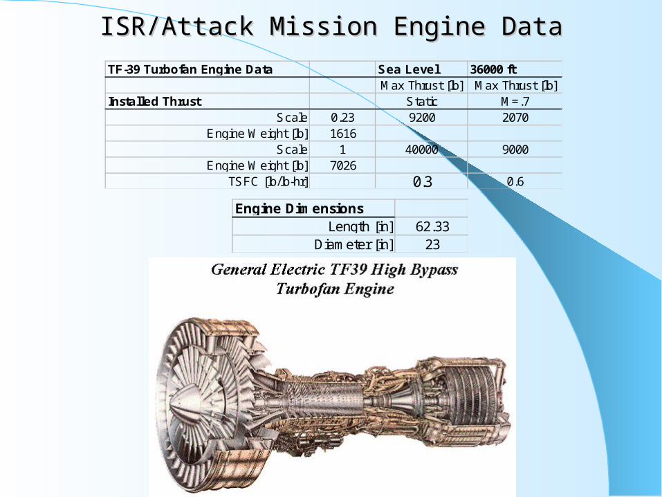
TF-39 Turbofan Engine Data Sea Level 36000 ftMax Thrust [lb] Max Thrust [lb]
Installed Thrust Static M=.7Scale 0.23 9200 2070
Engine Weight [lb] 1616Scale 1 40000 9000
Engine Weight [lb] 7026TSFC [lb/lb-hr] 0.3 0.6
ISR/Attack Mission Engine DataISR/Attack Mission Engine Data
Engine DimensionsLength [in] 62.33
Diameter [in] 23

ISR/Attack Mission SummaryISR/Attack Mission Summary
Meets mission requirements
-2600 nautical mile mission radius
-Load limit n=1.5 for reduced modular wing weight
-Take-off distance < 3200 ft capable
38500 lb take-off weight, 21425 lb empty weight
Fuselage 37.8 ft long, 74.3 ft wing span, Sref 395 ft^2
130 x 20 x 20 inch payload bay – 2000 lb payload capacity
Scaled TF-39 engine delivers 9200 lb static thrust
-Downscaled engine and module allows for fuel space

Other MentionablesOther Mentionables
Maintenance
-Easy accessible avionics components
-Quick engine and wing change through modular kits
Uncertainty
-Reduce uncertainty through refined estimates and analysis
-Wto uncertainty ~15%, Thrust and TSFC at maneuver ~10%
Materials
-Use modern light-weight composite materials and stealth
technology
Future Work
-Trade studies on long term cost savings for use of TF-39 engine from reduced TSFC
-Wind tunnel testing of model to refine aerodynamic performance

ReferencesReferences
L.M. Nicolai, Fundamentals of Aircraft Design, Revised 1984
D.P. Raymer, Aircraft Design: A Conceptual Approach, Third Edition, 1999