Embed Size (px)
Citation preview
TWO-HANDLE BATH & SHOWER SETwith THERMOSTATIC VALVE and TWO-WAY DIVERTER VALVE
InstallationInstructions
5535.5425535.5415535.1105535.105
Certified to comply withANSI A112.18.1M ASSE 1016
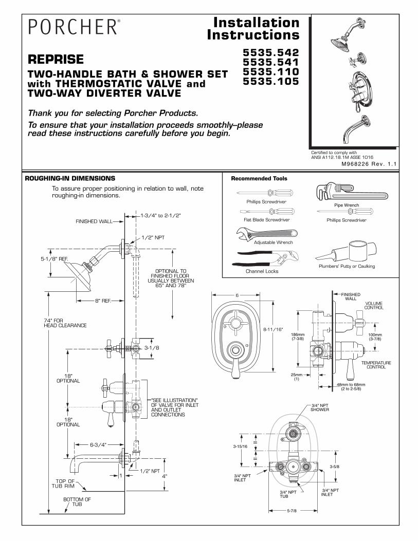
ROUGHING-IN DIMENSIONS
VOLUMECONTROL
TEMPERATURECONTROL
1-3/4" to 2-1/2"
M968226 Rev . 1 .1
M968226 Rev . 1 .1 M968226 Rev . 1 .1 M968226 Rev . 1 .1 M968226 Rev . 1 .1 M968226 Rev . 1 .1 M968226 Rev . 1 .1
REPRISE
To ensure that your installation proceeds smoothly--pleaseread these instructions carefully before you begin.
Thank you for selecting Porcher Products.
CO
LD
HOT
TEMP
To assure proper positioning in relation to wall, noteroughing-in dimensions.
FINISHED WALL
BOTTOM OFTUB
74" FORHEAD CLEARANCE
1/2" NPT
OPTIONAL TOFINISHED FLOOR
USUALLY BETWEEN65'' AND 78''
4"1/2" NPT
18"OPTIONAL
18"OPTIONAL
"SEE ILLUSTRATION"OF VALVE FOR INLETAND OUTLETCONNECTIONS
TOP OFTUB RIM
1
8" REF.
5-1/8" REF.
6-3/4"
3-1/8
Recommended Tools
Flat Blade Screwdriver
Adjustable Wrench
Channel LocksPlumbers' Putty or Caulking
Phillips Screwdriver
Phillips ScrewdriverPipe Wrench
8-11/16"
6
186mm(7-3/8)
100mm(3-7/8)
48mm to 68mm(2 to 2-5/8)
25mm(1)
FINISHEDWALL
5-7/8
IIII
3-15/16
3-5/8
3/4" NPTTUB
3/4" NPTINLET
3/4" NPTINLET
3/4" NPTSHOWER
1/2"NPT MIXEDDIVERTER INLET
1/2"NPTOUTLET
1/2"NPTOUTLET
HOT3/4" NPT
COLD INLET3/4" NPT
CROSSBRACE CROSS
BRACE
CROSSBRACE
3
67
2
1
TUB PORT MUSTBE PLUGGEDTUB PORT MUST
BE PLUGGED
DIVERTERVALVE
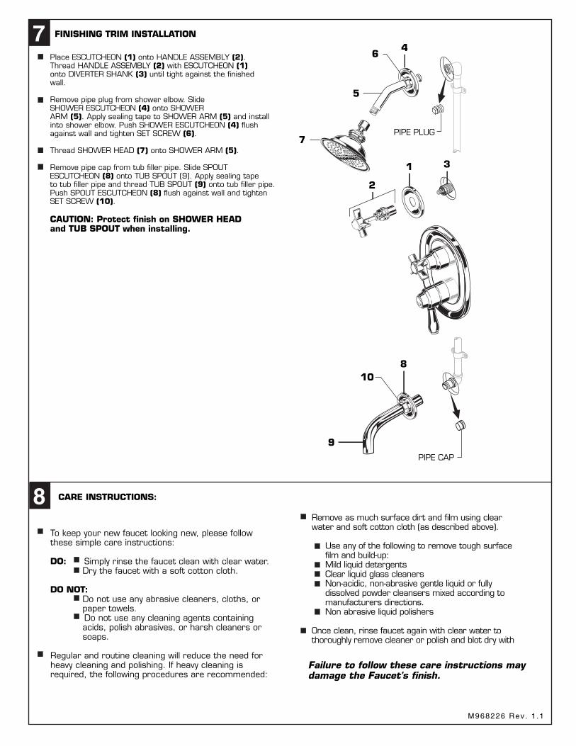
7 FINISHING TRIM INSTALLATION REPRISE
MODEL NUMBERS
5535.5425535.5415535.1105535.105
M962209-YYY0ASPOUT
M962208-YYY0ASPOUTESCUTCHEON
P r o d u c t n a m e s l i s t e d h e r e i n a r e t r a d e m a r k s o f P o r c h e r, L t d .© P o r c h e r, L t d . 2 0 0 8
IN CANADA 480-961-5353
For toll-free information and answers to your questions, call: 1 (800) 359-3261
Weekdays 8:00 to 7:00 p.m. EST
HOTLINE FOR HELP
CHROMEPOL. NICKELPOL. BRASSBRUSHED NICKEL
002008099295
Replace the "YYY" withappropriate finish code
PIPE PLUG
PIPE CAP
CO
LD
HOT
TEMP
46
5
1
2
3
8
9
10
CAUTION: Protect finish on SHOWER HEADand TUB SPOUT when installing.
Place ESCUTCHEON (1) onto HANDLE ASSEMBLY (2).Thread HANDLE ASSEMBLY (2) with ESCUTCHEON (1)onto DIVERTER SHANK (3) until tight against the finishedwall.
Remove pipe plug from shower elbow. SlideSHOWER ESCUTCHEON (4) onto SHOWERARM (5). Apply sealing tape to SHOWER ARM (5) and installinto shower elbow. Push SHOWER ESCUTCHEON (4) flushagainst wall and tighten SET SCREW (6).
Thread SHOWER HEAD (7) onto SHOWER ARM (5).
Remove pipe cap from tub filler pipe. Slide SPOUTESCUTCHEON (8) onto TUB SPOUT (9). Apply sealing tapeto tub filler pipe and thread TUB SPOUT (9) onto tub filler pipe.Push SPOUT ESCUTCHEON (8) flush against wall and tightenSET SCREW (10).
7
Remove as much surface dirt and film using clear water and soft cotton cloth (as described above). Use any of the following to remove tough surface film and build-up: Mild liquid detergents Clear liquid glass cleaners Non-acidic, non-abrasive gentle liquid or fully dissolved powder cleansers mixed according to manufacturers directions. Non abrasive liquid polishers
Once clean, rinse faucet again with clear water to thoroughly remove cleaner or polish and blot dry with
To keep your new faucet looking new, please followthese simple care instructions:
DO: Simply rinse the faucet clean with clear water. Dry the faucet with a soft cotton cloth.
DO NOT: Do not use any abrasive cleaners, cloths, or paper towels. Do not use any cleaning agents containing acids, polish abrasives, or harsh cleaners or soaps.
Regular and routine cleaning will reduce the need forheavy cleaning and polishing. If heavy cleaning isrequired, the following procedures are recommended:
8
Failure to follow these care instructions maydamage the Faucet's finish.
060220-0070ADIVERTER REPAIR KIT
M962205-YYY0ASHOWER ARM AND FLANGE KIT
M953570-YYY0ASHOWER HEAD
051310-0070ASPRING KIT
051309-0070ACAP
M962206-YYY0AHANDLE ASSEMBLY
912647-0070ACAP SEAL
060219-0070ASTEM KIT
M962207-YYY0AESCUTCHEON
M962204-0070AINDEX BUTTON
M968226A
M961113-YYY0AESCUTCHEON
913959-0070ASEAL
918434-YYY0AESCUTCHEON
SCREWS (2" LONG) A909776-YYY0AFRONT
COVER PLATE
952550-0070AVALVE KIT (2 VALVES)
A907093-YYY0ATEMPERATURE CAP
953957-0070ATEMPERATURE
CALIBRATION UNIT
A923358-0070ATEMPERATURE
LIMIT STOP
953963-0070AHANDLE EXTENSION
A907270-YYY0AVOLUME CAP
A953164-0070ADRIVE SHAFT
923143-0070ABACK PLATE
918327-0070ACLUTCH COVER SCREWS
923142-0070ACLUTCH COVER
911940-0070ARUBBER WASHER
M962209-YYY0ASPOUT
M962208-YYY0ASPOUT
ESCUTCHEON
954040-0070ATHERMOSTATIC
CARTRIDGE
953156-0070AGEAR
M908578-YYY0AVOLUME CONTROL
HANDLE
M961669-0070AVOLUME HANDLE
CAP
A954043-YYY0ATEMPERATURE HANDLE CAP
918555-0070AVOLUME HANDLE
SCREW
918416-0070ATEMPERATURE
HANDLE SCREW
M961112-YYY0ATEMPERATURE
CONTROL HANDLE
CO
L
D HOT
TEMP
CO
L
D HOT
TEMP
P r o d u c t n a m e s l i s t e d h e r e i n a r e t r a d e m a r k s o f P o r c h e r, L t d .© P o r c h e r, L t d . 2 0 0 2
IN CANADA 480-961-5353
For toll-free information and answers to your questions, call: 1 (800) 359-3261
Weekdays 8:00 to 7:00 p.m. EST
HOTLINE FOR HELP
CHROMEPOL. NICKELPOL. BRASSBRUSHED NICKEL
002008099295
Replace the "YYY" withappropriate finish code
060220-0070ADIVERTER REPAIR KIT
M962205-YYY0ASHOWER ARM AND FLANGE KIT
M953570-YYY0ASHOWER HEAD
051310-0070ASPRING KIT
051309-0070ACAP
M962206-YYY0AHANDLE ASSEMBLY
912647-0070ACAP SEAL
060219-0070ASTEM KIT
M962207-YYY0AESCUTCHEON
M962204-0070AINDEX BUTTON
TOP
WARNING
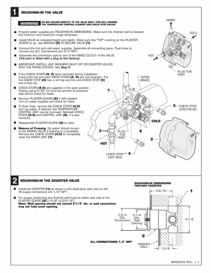
Prepare water supplies per ROUGHING-IN DIMENSIONS. Make sure the finished wall is betweenthe minimum and maximum rough dimension.
1 ROUGHING-IN THE VALVE
Install VALVE at indicated height and depth. Make sure the "TOP" marking on the PLASTERGUARD is up. Use BRACES (3) TO SECURE VALVE (1).
Connect the hot and cold water supplies. Assemble all connecting pipes. Flush lines toremove any dirt. Connections are 3/4" NPT.Assemble the connection pipe to one of the MIXED OUTLET of the VALVE.(Tub port is fitted with a plug at the factory).
IMPORTANT! INSTALL ANY REQUIRED SHUT OFF OR DIVERTER VALVESINTO THE PIPING SYSTEM. See Step 2.
DO NOT SOLDER DIRECTLY TO THE VALVE BODY; THIS WILL DAMAGETHE TEMPERATURE CONTROL ELEMENT AND CHECK STOP VALVES.
TOP
CHECK STOP(HOT RED)
PLUGTUB
PORT
CHECK STOP(COLD BLUE)
COLD
HOT
3
2
4
WOODBRACE
5
6
If the CHECK STOPS (4, 5) were removed during installation,ensure the hot and cold CHECK STOPS (4, 5) are not reversed. Thehot CHECK STOP (4) has a red top and the cold CHECK STOP (5)has a blue top.
CHECK STOPS (4,5) are supplied in the open position.Closing using 5/32" (4 mm) hex wrench to pressuretest and to check for leaks.
Reassemble PLASTER GUARD (2) to valve.
Beware of Freezing. No water should remainin the MIXING VALVE if freezing is a possibility.Remove the CHECK STOPS (4,5) to completelydrain the MIXER UNIT (1).
To flush lines, remove the CHECK STOPS (4,5)and run water. If desired, the TEMPERATURECONTROL UNIT can be removed. Reinstall CHECKSTOPS (4,5) and CONTROL UNIT (6), if it wasremoved.
MIXED
PLUG TUBPORT
COLD
3
4
5
HOT
1
TOP
MIXED
ROUGHING-IN THE DIVERTER VALVE
2
1
2
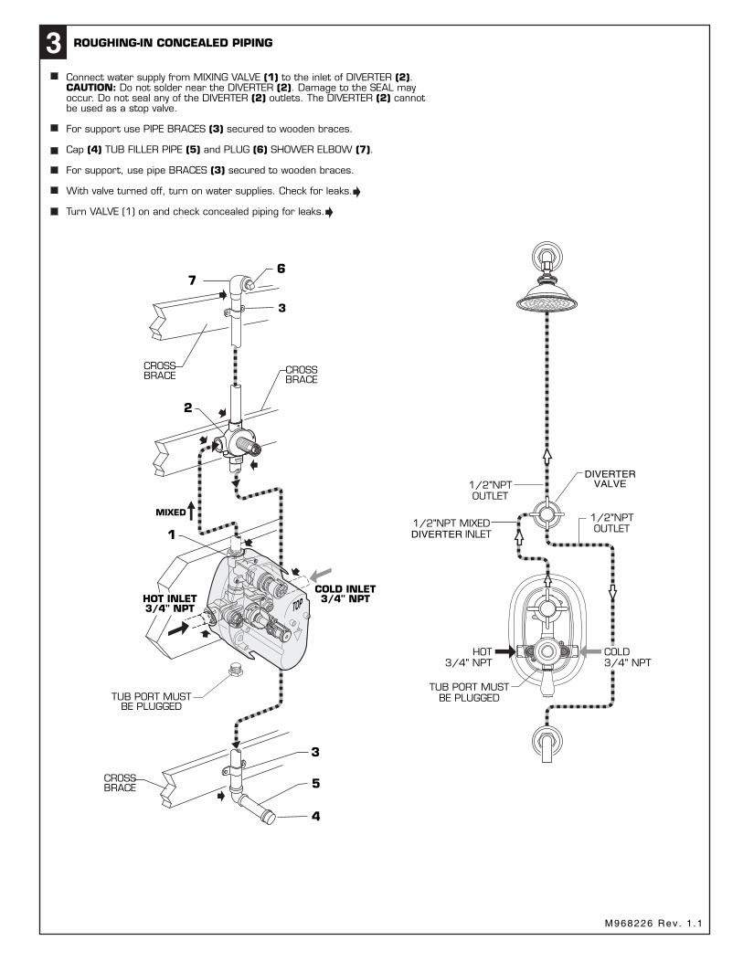
ROUGHING-IN CONCEALED PIPING3
Install the DIVERTER (1) as shown in the illustration with inlet on left.All supply connections are 1/2" NPT.
For proper positioning the finished wall must be within side wall of thePLASTER GUARD (2) (1-5/8" to 2-9/16").Note; Wall opening should not exceed 2-1/4" dia. or wall escutcheonmay not fully cover opening.
Connect water supply from MIXING VALVE (1) to the inlet of DIVERTER (2).CAUTION: Do not solder near the DIVERTER (2). Damage to the SEAL mayoccur. Do not seal any of the DIVERTER (2) outlets. The DIVERTER (2) cannotbe used as a stop valve.
For support use PIPE BRACES (3) secured to wooden braces.
Cap (4) TUB FILLER PIPE (5) and PLUG (6) SHOWER ELBOW (7).
For support, use pipe BRACES (3) secured to wooden braces.
With valve turned off, turn on water supplies. Check for leaks.
Turn VALVE (1) on and check concealed piping for leaks.
ROUGHING-IN DIMENSIONSTWO-WAY DIVERTER
1-5/8
FINISHEDWALL
2-9/16
3-1/8
2-1/4(Dia.Wall
Opening)
2-3/4(Dia.
Escutcheon)
ALL CONNECTIONS 1/2" NPT
COLD3/4" NPT
HOT INLET3/4" NPT
TOP
1Remove PLASTER GUARD (1).
OFF
ON
3
4
4
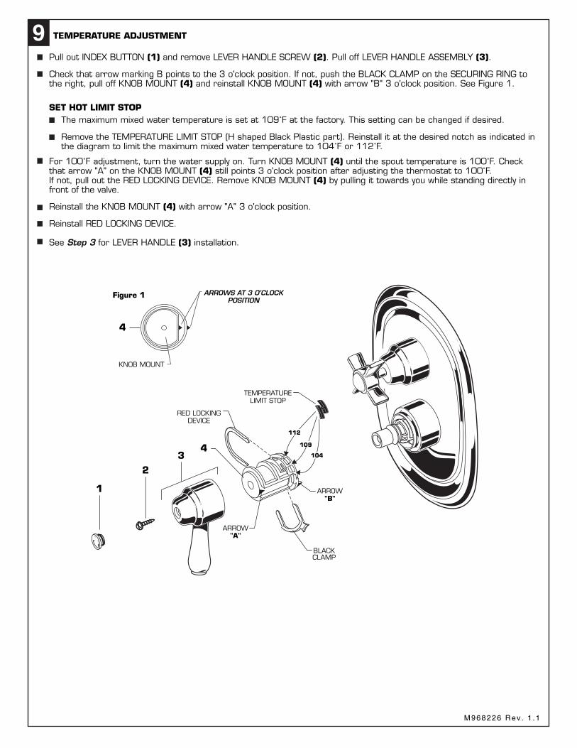
9 TEMPERATURE ADJUSTMENT
SET HOT LIMIT STOP
Check that arrow marking B points to the 3 o'clock position. If not, push the BLACK CLAMP on the SECURING RING tothe right, pull off KNOB MOUNT (4) and reinstall KNOB MOUNT (4) with arrow "B" 3 o'clock position. See Figure 1.
For 100˚F adjustment, turn the water supply on. Turn KNOB MOUNT (4) until the spout temperature is 100˚F. Checkthat arrow "A" on the KNOB MOUNT (4) still points 3 o'clock position after adjusting the thermostat to 100˚F.If not, pull out the RED LOCKING DEVICE. Remove KNOB MOUNT (4) by pulling it towards you while standing directly infront of the valve.
Reinstall the KNOB MOUNT (4) with arrow "A" 3 o'clock position.
The maximum mixed water temperature is set at 109˚F at the factory. This setting can be changed if desired.
Remove the TEMPERATURE LIMIT STOP (H shaped Black Plastic part). Reinstall it at the desired notch as indicated inthe diagram to limit the maximum mixed water temperature to 104˚F or 112˚F.
Reinstall RED LOCKING DEVICE.
See Step 3 for LEVER HANDLE (3) installation.
Pull out INDEX BUTTON (1) and remove LEVER HANDLE SCREW (2). Pull off LEVER HANDLE ASSEMBLY (3).
ARROW"A"
BLACKCLAMP
ARROW"B"
RED LOCKINGDEVICE
TEMPERATURELIMIT STOP
2
1
ARROWS AT 3 O'CLOCKPOSITION
Figure 1
KNOB MOUNT
112
109
104
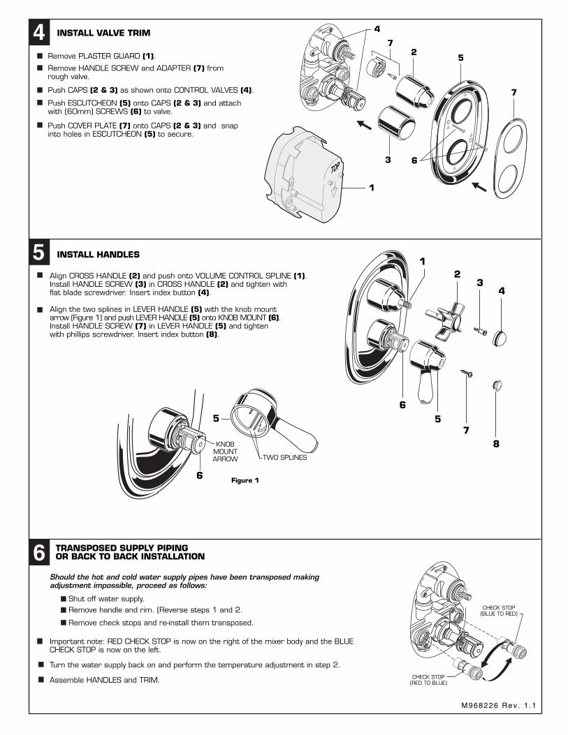
Remove HANDLE SCREW and ADAPTER (7) fromrough valve.
4
Push CAPS (2 & 3) as shown onto CONTROL VALVES (4).
INSTALL VALVE TRIM
Push ESCUTCHEON (5) onto CAPS (2 & 3) and attachwith (60mm) SCREWS (6) to valve.
Push COVER PLATE (7) onto CAPS (2 & 3) and snapinto holes in ESCUTCHEON (5) to secure.
4
3
27
5
7
6
1
Should the hot and cold water supply pipes have been transposed makingadjustment impossible, proceed as follows:
TRANSPOSED SUPPLY PIPINGOR BACK TO BACK INSTALLATION6
Remove check stops and re-install them transposed.
Shut off water supply.Remove handle and rim. (Reverse steps 1 and 2.
CHECK STOP(RED TO BLUE)
Turn the water supply back on and perform the temperature adjustment in step 2.
Assemble HANDLES and TRIM.
CHECK STOP(BLUE TO RED)
M908578-YYY0AVOLUME CONTROL
HANDLE
918555-0070AVOLUME HANDLE SCREW
M961669-0070AVOLUME HANDLE CAP
A954043-YYY0ATEMPERATURE HANDLE CAP
918416-0070ATEMPERATURE
HANDLE SCREW
M961112-YYY0ATEMPERATURE
CONTROL HANDLE
918434-YYY0AESCUTCHEON SCREWS
M909625-YYY0AFRONT COVER PLATE
M962365-YYY0AESCUTCHEON
M907093-YYY0AVOLUME CAP
907090-YYY0ATEMPERATURE CAP
Important note: RED CHECK STOP is now on the right of the mixer body and the BLUECHECK STOP is now on the left.
23
4
6
6
557
8
15 INSTALL HANDLES
TWO SPLINES
KNOBMOUNTARROW
Figure 1
OF
F
ON
Align CROSS HANDLE (2) and push onto VOLUME CONTROL SPLINE (1).Install HANDLE SCREW (3) in CROSS HANDLE (2) and tighten withflat blade screwdriver. Insert index button (4).
Align the two splines in LEVER HANDLE (5) with the knob mountarrow (Figure 1) and push LEVER HANDLE (5) onto KNOB MOUNT (6).Install HANDLE SCREW (7) in LEVER HANDLE (5) and tightenwith phillips screwdriver. Insert index button (8).
923348-0070AHANDLE ADAPTER
A994352-0070ACARTRIDGE
954040-0070ATHERMOSTAT
CARTRIDGE
912647-0070AO-RING
953963-0070AHANDLE EXTENSION
953957-0070ATEMPERATURE
CALIBRATION UNIT
A953971-0070ACHECK STOP (COLD BLUE)
A953972-0070ACHECK STOP
(HOT RED)
918428-0070ACARTRIDGE SCREW
912647-0070AO-RING
TWO-HANDLE BATH & SHOWER SETwith THERMOSTATIC VALVE and
TWO-WAY DIVERTER VALVE
REPRISE
MODEL NUMBERS
5535.5425535.5415535.1105535.105
TWO-HANDLE BATH & SHOWER SETwith THERMOSTATIC VALVE and
TWO-WAY DIVERTER VALVE
CARE INSTRUCTIONS:
Remove PLASTER GUARD (2) if still installed.Turn on water supplies and check for leaks
BEFOREJan. 2008
AFTERJan. 2008
TWO-HANDLE BATH & SHOWER SETwith THERMOSTATIC VALVE and TWO-WAY DIVERTER VALVE
InstallationInstructions
5535.5425535.5415535.1105535.105
Certified to comply withANSI A112.18.1M ASSE 1016
ROUGHING-IN DIMENSIONS
VOLUMECONTROL
TEMPERATURECONTROL
1-3/4" to 2-1/2"
M968226 Rev . 1 .1
M968226 Rev . 1 .1 M968226 Rev . 1 .1 M968226 Rev . 1 .1 M968226 Rev . 1 .1 M968226 Rev . 1 .1 M968226 Rev . 1 .1
REPRISE
To ensure that your installation proceeds smoothly--pleaseread these instructions carefully before you begin.
Thank you for selecting Porcher Products.
CO
LD
HOT
TEMP
To assure proper positioning in relation to wall, noteroughing-in dimensions.
FINISHED WALL
BOTTOM OFTUB
74" FORHEAD CLEARANCE
1/2" NPT
OPTIONAL TOFINISHED FLOOR
USUALLY BETWEEN65'' AND 78''
4"1/2" NPT
18"OPTIONAL
18"OPTIONAL
"SEE ILLUSTRATION"OF VALVE FOR INLETAND OUTLETCONNECTIONS
TOP OFTUB RIM
1
8" REF.
5-1/8" REF.
6-3/4"
3-1/8
Recommended Tools
Flat Blade Screwdriver
Adjustable Wrench
Channel LocksPlumbers' Putty or Caulking
Phillips Screwdriver
Phillips ScrewdriverPipe Wrench
8-11/16"
6
186mm(7-3/8)
100mm(3-7/8)
48mm to 68mm(2 to 2-5/8)
25mm(1)
FINISHEDWALL
5-7/8
IIII
3-15/16
3-5/8
3/4" NPTTUB
3/4" NPTINLET
3/4" NPTINLET
3/4" NPTSHOWER
1/2"NPT MIXEDDIVERTER INLET
1/2"NPTOUTLET
1/2"NPTOUTLET
HOT3/4" NPT
COLD INLET3/4" NPT
CROSSBRACE CROSS
BRACE
CROSSBRACE
3
67
2
1
TUB PORT MUSTBE PLUGGEDTUB PORT MUST
BE PLUGGED
DIVERTERVALVE
7 FINISHING TRIM INSTALLATION REPRISE
MODEL NUMBERS
5535.5425535.5415535.1105535.105
M962209-YYY0ASPOUT
M962208-YYY0ASPOUTESCUTCHEON
P r o d u c t n a m e s l i s t e d h e r e i n a r e t r a d e m a r k s o f P o r c h e r, L t d .© P o r c h e r, L t d . 2 0 0 8
IN CANADA 480-961-5353
For toll-free information and answers to your questions, call: 1 (800) 359-3261
Weekdays 8:00 to 7:00 p.m. EST
HOTLINE FOR HELP
CHROMEPOL. NICKELPOL. BRASSBRUSHED NICKEL
002008099295
Replace the "YYY" withappropriate finish code
PIPE PLUG
PIPE CAP
CO
LD
HOT
TEMP
46
5
1
2
3
8
9
10
CAUTION: Protect finish on SHOWER HEADand TUB SPOUT when installing.
Place ESCUTCHEON (1) onto HANDLE ASSEMBLY (2).Thread HANDLE ASSEMBLY (2) with ESCUTCHEON (1)onto DIVERTER SHANK (3) until tight against the finishedwall.
Remove pipe plug from shower elbow. SlideSHOWER ESCUTCHEON (4) onto SHOWERARM (5). Apply sealing tape to SHOWER ARM (5) and installinto shower elbow. Push SHOWER ESCUTCHEON (4) flushagainst wall and tighten SET SCREW (6).
Thread SHOWER HEAD (7) onto SHOWER ARM (5).
Remove pipe cap from tub filler pipe. Slide SPOUTESCUTCHEON (8) onto TUB SPOUT (9). Apply sealing tapeto tub filler pipe and thread TUB SPOUT (9) onto tub filler pipe.Push SPOUT ESCUTCHEON (8) flush against wall and tightenSET SCREW (10).
7
Remove as much surface dirt and film using clear water and soft cotton cloth (as described above). Use any of the following to remove tough surface film and build-up: Mild liquid detergents Clear liquid glass cleaners Non-acidic, non-abrasive gentle liquid or fully dissolved powder cleansers mixed according to manufacturers directions. Non abrasive liquid polishers
Once clean, rinse faucet again with clear water to thoroughly remove cleaner or polish and blot dry with
To keep your new faucet looking new, please followthese simple care instructions:
DO: Simply rinse the faucet clean with clear water. Dry the faucet with a soft cotton cloth.
DO NOT: Do not use any abrasive cleaners, cloths, or paper towels. Do not use any cleaning agents containing acids, polish abrasives, or harsh cleaners or soaps.
Regular and routine cleaning will reduce the need forheavy cleaning and polishing. If heavy cleaning isrequired, the following procedures are recommended:
8
Failure to follow these care instructions maydamage the Faucet's finish.
060220-0070ADIVERTER REPAIR KIT
M962205-YYY0ASHOWER ARM AND FLANGE KIT
M953570-YYY0ASHOWER HEAD
051310-0070ASPRING KIT
051309-0070ACAP
M962206-YYY0AHANDLE ASSEMBLY
912647-0070ACAP SEAL
060219-0070ASTEM KIT
M962207-YYY0AESCUTCHEON
M962204-0070AINDEX BUTTON
M968226A
M961113-YYY0AESCUTCHEON
913959-0070ASEAL
918434-YYY0AESCUTCHEON
SCREWS (2" LONG) A909776-YYY0AFRONT
COVER PLATE
952550-0070AVALVE KIT (2 VALVES)
A907093-YYY0ATEMPERATURE CAP
953957-0070ATEMPERATURE
CALIBRATION UNIT
A923358-0070ATEMPERATURE
LIMIT STOP
953963-0070AHANDLE EXTENSION
A907270-YYY0AVOLUME CAP
A953164-0070ADRIVE SHAFT
923143-0070ABACK PLATE
918327-0070ACLUTCH COVER SCREWS
923142-0070ACLUTCH COVER
911940-0070ARUBBER WASHER
M962209-YYY0ASPOUT
M962208-YYY0ASPOUT
ESCUTCHEON
954040-0070ATHERMOSTATIC
CARTRIDGE
953156-0070AGEAR
M908578-YYY0AVOLUME CONTROL
HANDLE
M961669-0070AVOLUME HANDLE
CAP
A954043-YYY0ATEMPERATURE HANDLE CAP
918555-0070AVOLUME HANDLE
SCREW
918416-0070ATEMPERATURE
HANDLE SCREW
M961112-YYY0ATEMPERATURE
CONTROL HANDLE
CO
L
D HOT
TEMP
CO
L
D HOT
TEMP
P r o d u c t n a m e s l i s t e d h e r e i n a r e t r a d e m a r k s o f P o r c h e r, L t d .© P o r c h e r, L t d . 2 0 0 2
IN CANADA 480-961-5353
For toll-free information and answers to your questions, call: 1 (800) 359-3261
Weekdays 8:00 to 7:00 p.m. EST
HOTLINE FOR HELP
CHROMEPOL. NICKELPOL. BRASSBRUSHED NICKEL
002008099295
Replace the "YYY" withappropriate finish code
060220-0070ADIVERTER REPAIR KIT
M962205-YYY0ASHOWER ARM AND FLANGE KIT
M953570-YYY0ASHOWER HEAD
051310-0070ASPRING KIT
051309-0070ACAP
M962206-YYY0AHANDLE ASSEMBLY
912647-0070ACAP SEAL
060219-0070ASTEM KIT
M962207-YYY0AESCUTCHEON
M962204-0070AINDEX BUTTON
TOP
WARNING
Prepare water supplies per ROUGHING-IN DIMENSIONS. Make sure the finished wall is betweenthe minimum and maximum rough dimension.
1 ROUGHING-IN THE VALVE
Install VALVE at indicated height and depth. Make sure the "TOP" marking on the PLASTERGUARD is up. Use BRACES (3) TO SECURE VALVE (1).
Connect the hot and cold water supplies. Assemble all connecting pipes. Flush lines toremove any dirt. Connections are 3/4" NPT.Assemble the connection pipe to one of the MIXED OUTLET of the VALVE.(Tub port is fitted with a plug at the factory).
IMPORTANT! INSTALL ANY REQUIRED SHUT OFF OR DIVERTER VALVESINTO THE PIPING SYSTEM. See Step 2.
DO NOT SOLDER DIRECTLY TO THE VALVE BODY; THIS WILL DAMAGETHE TEMPERATURE CONTROL ELEMENT AND CHECK STOP VALVES.
TOP
CHECK STOP(HOT RED)
PLUGTUB
PORT
CHECK STOP(COLD BLUE)
COLD
HOT
3
2
4
WOODBRACE
5
6
If the CHECK STOPS (4, 5) were removed during installation,ensure the hot and cold CHECK STOPS (4, 5) are not reversed. Thehot CHECK STOP (4) has a red top and the cold CHECK STOP (5)has a blue top.
CHECK STOPS (4,5) are supplied in the open position.Closing using 5/32" (4 mm) hex wrench to pressuretest and to check for leaks.
Reassemble PLASTER GUARD (2) to valve.
Beware of Freezing. No water should remainin the MIXING VALVE if freezing is a possibility.Remove the CHECK STOPS (4,5) to completelydrain the MIXER UNIT (1).
To flush lines, remove the CHECK STOPS (4,5)and run water. If desired, the TEMPERATURECONTROL UNIT can be removed. Reinstall CHECKSTOPS (4,5) and CONTROL UNIT (6), if it wasremoved.
MIXED
PLUG TUBPORT
COLD
3
4
5
HOT
1
TOP
MIXED
ROUGHING-IN THE DIVERTER VALVE
2
1
2
ROUGHING-IN CONCEALED PIPING3
Install the DIVERTER (1) as shown in the illustration with inlet on left.All supply connections are 1/2" NPT.
For proper positioning the finished wall must be within side wall of thePLASTER GUARD (2) (1-5/8" to 2-9/16").Note; Wall opening should not exceed 2-1/4" dia. or wall escutcheonmay not fully cover opening.
Connect water supply from MIXING VALVE (1) to the inlet of DIVERTER (2).CAUTION: Do not solder near the DIVERTER (2). Damage to the SEAL mayoccur. Do not seal any of the DIVERTER (2) outlets. The DIVERTER (2) cannotbe used as a stop valve.
For support use PIPE BRACES (3) secured to wooden braces.
Cap (4) TUB FILLER PIPE (5) and PLUG (6) SHOWER ELBOW (7).
For support, use pipe BRACES (3) secured to wooden braces.
With valve turned off, turn on water supplies. Check for leaks.
Turn VALVE (1) on and check concealed piping for leaks.
ROUGHING-IN DIMENSIONSTWO-WAY DIVERTER
1-5/8
FINISHEDWALL
2-9/16
3-1/8
2-1/4(Dia.Wall
Opening)
2-3/4(Dia.
Escutcheon)
ALL CONNECTIONS 1/2" NPT
COLD3/4" NPT
HOT INLET3/4" NPT
TOP
1Remove PLASTER GUARD (1).
OFF
ON
3
4
4
9 TEMPERATURE ADJUSTMENT
SET HOT LIMIT STOP
Check that arrow marking B points to the 3 o'clock position. If not, push the BLACK CLAMP on the SECURING RING tothe right, pull off KNOB MOUNT (4) and reinstall KNOB MOUNT (4) with arrow "B" 3 o'clock position. See Figure 1.
For 100˚F adjustment, turn the water supply on. Turn KNOB MOUNT (4) until the spout temperature is 100˚F. Checkthat arrow "A" on the KNOB MOUNT (4) still points 3 o'clock position after adjusting the thermostat to 100˚F.If not, pull out the RED LOCKING DEVICE. Remove KNOB MOUNT (4) by pulling it towards you while standing directly infront of the valve.
Reinstall the KNOB MOUNT (4) with arrow "A" 3 o'clock position.
The maximum mixed water temperature is set at 109˚F at the factory. This setting can be changed if desired.
Remove the TEMPERATURE LIMIT STOP (H shaped Black Plastic part). Reinstall it at the desired notch as indicated inthe diagram to limit the maximum mixed water temperature to 104˚F or 112˚F.
Reinstall RED LOCKING DEVICE.
See Step 3 for LEVER HANDLE (3) installation.
Pull out INDEX BUTTON (1) and remove LEVER HANDLE SCREW (2). Pull off LEVER HANDLE ASSEMBLY (3).
ARROW"A"
BLACKCLAMP
ARROW"B"
RED LOCKINGDEVICE
TEMPERATURELIMIT STOP
2
1
ARROWS AT 3 O'CLOCKPOSITION
Figure 1
KNOB MOUNT
112
109
104
Remove HANDLE SCREW and ADAPTER (7) fromrough valve.
4
Push CAPS (2 & 3) as shown onto CONTROL VALVES (4).
INSTALL VALVE TRIM
Push ESCUTCHEON (5) onto CAPS (2 & 3) and attachwith (60mm) SCREWS (6) to valve.
Push COVER PLATE (7) onto CAPS (2 & 3) and snapinto holes in ESCUTCHEON (5) to secure.
4
3
27
5
7
6
1
Should the hot and cold water supply pipes have been transposed makingadjustment impossible, proceed as follows:
TRANSPOSED SUPPLY PIPINGOR BACK TO BACK INSTALLATION6
Remove check stops and re-install them transposed.
Shut off water supply.Remove handle and rim. (Reverse steps 1 and 2.
CHECK STOP(RED TO BLUE)
Turn the water supply back on and perform the temperature adjustment in step 2.
Assemble HANDLES and TRIM.
CHECK STOP(BLUE TO RED)
M908578-YYY0AVOLUME CONTROL
HANDLE
918555-0070AVOLUME HANDLE SCREW
M961669-0070AVOLUME HANDLE CAP
A954043-YYY0ATEMPERATURE HANDLE CAP
918416-0070ATEMPERATURE
HANDLE SCREW
M961112-YYY0ATEMPERATURE
CONTROL HANDLE
918434-YYY0AESCUTCHEON SCREWS
M909625-YYY0AFRONT COVER PLATE
M962365-YYY0AESCUTCHEON
M907093-YYY0AVOLUME CAP
907090-YYY0ATEMPERATURE CAP
Important note: RED CHECK STOP is now on the right of the mixer body and the BLUECHECK STOP is now on the left.
23
4
6
6
557
8
15 INSTALL HANDLES
TWO SPLINES
KNOBMOUNTARROW
Figure 1
OF
F
ON
Align CROSS HANDLE (2) and push onto VOLUME CONTROL SPLINE (1).Install HANDLE SCREW (3) in CROSS HANDLE (2) and tighten withflat blade screwdriver. Insert index button (4).
Align the two splines in LEVER HANDLE (5) with the knob mountarrow (Figure 1) and push LEVER HANDLE (5) onto KNOB MOUNT (6).Install HANDLE SCREW (7) in LEVER HANDLE (5) and tightenwith phillips screwdriver. Insert index button (8).
923348-0070AHANDLE ADAPTER
A994352-0070ACARTRIDGE
954040-0070ATHERMOSTAT
CARTRIDGE
912647-0070AO-RING
953963-0070AHANDLE EXTENSION
953957-0070ATEMPERATURE
CALIBRATION UNIT
A953971-0070ACHECK STOP (COLD BLUE)
A953972-0070ACHECK STOP
(HOT RED)
918428-0070ACARTRIDGE SCREW
912647-0070AO-RING
TWO-HANDLE BATH & SHOWER SETwith THERMOSTATIC VALVE and
TWO-WAY DIVERTER VALVE
REPRISE
MODEL NUMBERS
5535.5425535.5415535.1105535.105
TWO-HANDLE BATH & SHOWER SETwith THERMOSTATIC VALVE and
TWO-WAY DIVERTER VALVE
CARE INSTRUCTIONS:
Remove PLASTER GUARD (2) if still installed.Turn on water supplies and check for leaks
BEFOREJan. 2008
AFTERJan. 2008
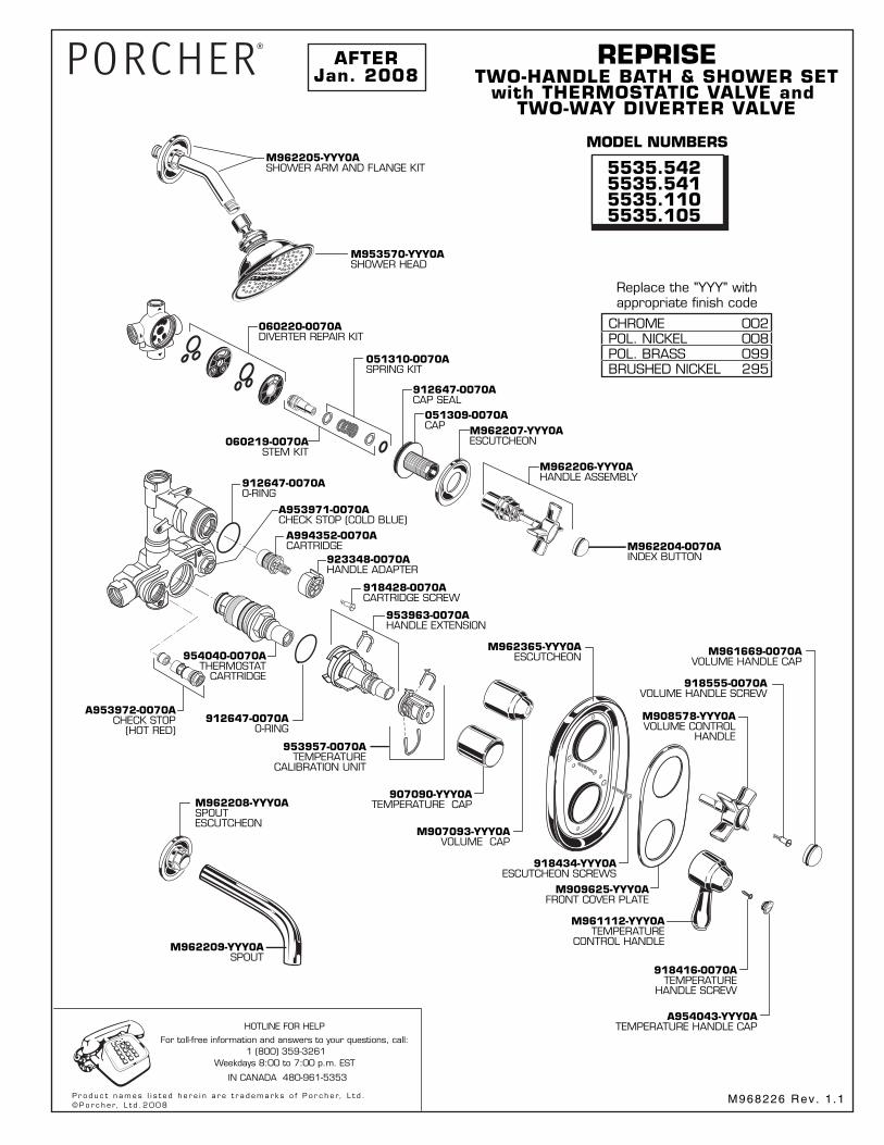
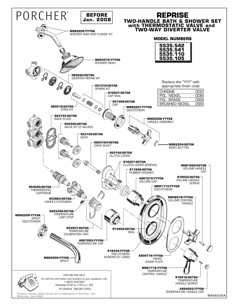
![The Warner/Reprise Loss Leaders Series2020].pdf · The Warner/Reprise Loss Leaders Series WW# Title Catalog # Year 1 The 1969 Warner/Reprise Songbook PRO331 1969 2 The 1969 Warner/Reprise](https://img.pdfslide.us/doc/110x75/5f314e2e8020d715c024ec90/the-warnerreprise-loss-leaders-series-2020pdf-the-warnerreprise-loss-leaders.jpg)