Embed Size (px)
Citation preview
way of generating atomically well-defined edgesthat make graphene-based electronics possible.
References and Notes1. K. S. Novoselov et al., Science 306, 666 (2004).2. K. S. Novoselov et al., Proc. Natl. Acad. Sci. U.S.A. 102,
10451 (2005).3. Y. Zhang, Y. W. Tan, H. L. Stormer, P. Kim, Nature 438,
201 (2005).4. J. C. Meyer et al., Nature 446, 60 (2007).5. A. K. Geim, K. S. Novoselov, Nat. Mater. 6, 183 (2007).6. Y. W. Son, M. L. Cohen, S. G. Louie,Nature 444, 347 (2006).7. X. Li, X. Wang, L. Zhang, S. Lee, H. Dai, Science 319,
1229 (2008); published online 23 January 2008(10.1126/science.1150878).
8. T. Enoki, Y. Kobayashi, K. Fukui, Int. Rev. Phys. Chem.26, 609 (2007).
9. K. Nakada, M. Fujita, G. Dresselhaus, M. S. Dresselhaus,Phys. Rev. B 54, 17954 (1996).
10. K. Wakabayashi, Phys. Rev. B 64, 125428 (2001).11. L. G. Cançado et al., Phys. Rev. Lett. 93, 047403 (2004).12. L. G. Cançado, M. A. Pimenta, B. R. A. Neves, M. S. S.
Dantas, A. Jorio, Phys. Rev. Lett. 93, 247401 (2004).13. P. Shemella, Y. Zhang, M. Mailman, P. M. Ajayan,
S. K. Nayak, Appl. Phys. Lett. 91, 042101 (2007).14. L. Yang, C. H. Park, Y. W. Son, M. L. Cohen, S. G. Louie,
Phys. Rev. Lett. 99, 186801 (2007).
15. X. Wang et al., Phys. Rev. Lett. 100, 206803 (2008).16. T. C. Li, S. P. Lu, Phys. Rev. B 77, 085408 (2008).17. F. Cervantes-Sodi, G. Csányi, S. Piscanec, A. C. Ferrari,
Phys. Rev. B 77, 165427 (2008).18. L. Tapasztó, G. Dobrik, P. Lambin, L. P. Biró, Nat.
Nanotechnol. 3, 397 (2008).19. M. Y. Han, B. Özyilmaz, Y. Zhang, P. Kim, Phys. Rev. Lett.
98, 206805 (2007).20. J. Campos-Delgado et al., Nano Lett. 8, 2773 (2008).21. F. Banhart, Rep. Prog. Phys. 62, 1181 (1999).22. B. T. Kelly, Physics of Graphite (Applied Science
Publishers, London, 1981).23. J. Goma, A. Oberlin, Thin Solid Films 65, 221 (1980).24. J. N. Rouzaud, A. Oberlin, C. Beny-Bassez, Thin Solid
Films 105, 75 (1983).25. C. Jin, K. Suenaga, S. Iijima, Nano Lett. 8, 1127 (2008).26. Y. W. Son, M. L. Cohen, S. G. Louie, Phys. Rev. Lett. 97,
216803 (2006).27. M. Vandescuren, P. Hermet, V. Meunier, L. Henrard, Ph.
Lambin, Phys. Rev. B 78, 195401 (2008).28. S. Latil, V. Meunier, L. Henrard, Phys. Rev. B 76, 201402
(2007).29. D. A. Areshkin, D. Gunlycke, C. T. White, Nano Lett. 7,
204 (2007).30. We thank Z. Ren, S. Chen, B. I. Yakobson, S. Gradecak,
G. Dresselhaus, and G. Chen for valuable and fruitfuldiscussions, and E. Gracia-Espino for providing thePt-coated ribbons that we used in some experiments.
This work was supported by NSF grant NanoscaleInterdisciplinary Research Teams CTS-05-06830. We alsothank Consejo Nacional de Ciencia y Tecnología(CONACYT)–Mexico for grants 56787 (Laboratory forNanoscience and Nanotechnology Research–LINAN),45772 (M.T.), 41464–Interamerican Collaboration (M.T.),2004-01-013/SALUD-CONACYT (M.T.), and Ph.D.scholarships ( J.C.-D. and J.M.R.-H.). A portion of thepresent research was supported in part by the LaboratoryDirected Research and Development Program of ORNL,managed by UT-Battelle, by the Division of MaterialsScience and Engineering, U.S. Department of Energy,and by the Center for Nanophase Materials Sciences,sponsored by the Division of Scientific User Facilities,U.S. Department of Energy (V.M. and B.G.S.). A patentthat is related to the production of these graphicnanoribbons has been submitted by some of the authorsand holds the U.S. patent application number 12/042,544.
Supporting Online Materialwww.sciencemag.org/cgi/content/full/323/5922/1701/DC1Materials and MethodsSOM TextFigs. S1 to S6References
6 October 2008; accepted 10 February 200910.1126/science.1166862
Graphene at the Edge:Stability and DynamicsÇağlar Ö. Girit,1,2 Jannik C. Meyer,1,2 Rolf Erni,3 Marta D. Rossell,3 C. Kisielowski,3 Li Yang,1,2Cheol-Hwan Park,1,2 M. F. Crommie,1,2 Marvin L. Cohen,1,2 Steven G. Louie,1,2 A. Zettl1,2*
Although the physics of materials at surfaces and edges has been extensively studied, themovement of individual atoms at an isolated edge has not been directly observed in real time. Witha transmission electron aberration–corrected microscope capable of simultaneous atomic spatialresolution and 1-second temporal resolution, we produced movies of the dynamics of carbon atomsat the edge of a hole in a suspended, single atomic layer of graphene. The rearrangement of bondsand beam-induced ejection of carbon atoms are recorded as the hole grows. We investigated themechanism of edge reconstruction and demonstrated the stability of the “zigzag” edgeconfiguration. This study of an ideal low-dimensional interface, a hole in graphene, exhibits thecomplex behavior of atoms at a boundary.
Graphene, a single atomic layer of carbonatoms bonded in a hexagonal lattice, isone of few materials that are stable in
two dimensions (1) and free-standing when sus-pended (2). This unexpected stability (3), combinedwith its exotic band structure and other unusualphysical properties (4), has led to a considerableamount of experimental research (5–11). Of themany theoretical studies of graphene, a substan-tial portion are devoted to the physics of grapheneedges, whose structure in narrow graphene ribbonsis predicted to have a major impact on their elec-tronic properties (12, 13). Experimental studies ofthe graphene edge have lagged behind, mainly due
to the difficulty of atomically resolving and char-acterizing the boundaries of graphene sheets, butwould give insight into the one-dimensional (1D)interface of a purely 2D structure.
The traditional method of obtaining atomicresolution on surfaces and edges is scanning tun-neling microscopy (STM) or atomic force micros-copy (AFM). Although there are several atomicallyresolved AFM/STM studies of graphene (14–16),as well as studies of step edges in graphite (17),there are several problems in observing dynamicsof the edge atomswith scanning probe techniques.First, typical scan speeds are on the order of mi-nutes to hours, which may be too slow to capturethe movement of atoms. Second, the highest res-olution and stability is obtained at cryogenic tem-perature, where the dynamics may be frozen out.Finally, the sample is usually on a substrate, whichcan strongly influence the behavior of atoms bothin the bulk and at the edge. To observe dynamicson a time scale of seconds, the only alternative to
scanning probe microscopes with comparablespatial resolution is the transmission electron mi-croscope (TEM). Indeed, the dynamics of atomcolumns composed of heavy atomswere observedin this manner (18).
Traditional TEMs lack the necessary resolu-tion at the low operating voltages required toavoid immediate sample damage. Previous 100to 200 kV TEM studies of few-layer graphiticmaterials showed that some microscopes havedifficulty resolving the lattice and are not capableof atomically resolving edges (19–21), makingimage interpretation ambiguous. By using theTransmission Electron Aberration-corrected Mi-croscope monochromated (TEAM 0.5) (22), ca-pable of sub-Ångstrom resolution even at 80 kV,we imaged every carbon atom in the lattice ofsuspended single-layer graphene (23). We em-ployed the same microscope to record the dy-namics of carbon atoms on the edge of a hole ina graphene sheet. The sample was prepared asdescribed previously (24), and details of the mi-croscope configuration can be found in (23). Theentire experiment was conducted in the high-vacuum environment (<10−7 mbar) of the micro-scope chamber.
MovieS1 shows the evolution of the holewithina suspended graphene sheet. Each frame averages1 s of exposure, and the frames themselves are 4 sapart. The carbon atoms are shown as white becausethe spherical aberration was chosen to be negative(25). The spatial sampling is 26 T 4 pm/pixel,determined by fitting for the measured atomic po-sitions and using the known atomic spacing of1.42 Å. Figure 1A shows the first frame of thesequence. The hole, initially formed through pro-longed irradiation by the electron beam, is clearlyvisible near the center of the frame and is sur-rounded by the hexagonal carbon lattice. The struc-tures lining the boundary of the frame are adsorbates
1Department of Physics, University of California at Berkeley,Berkeley, CA 94720,USA. 2Materials Sciences Division, LawrenceBerkeley National Laboratory, Berkeley, CA 94720, USA.3National Center for Electron Microscopy, Lawrence BerkeleyNational Laboratory, Berkeley, CA 94720, USA.
*To whom correspondence should be addressed. E-mail:[email protected]
www.sciencemag.org SCIENCE VOL 323 27 MARCH 2009 1705
REPORTS
on
Janu
ary
12, 2
010
ww
w.s
cien
cem
ag.o
rgD
ownl
oade
d fr
om
most likely deposited during the process of sus-pending the graphene sheet. Every carbon atomin the lattice is resolved, including those at theedge of the hole. Although there is a possibilitythat edge atoms could be terminated by hydrogenor other functional groups, there is no reason ex-perimentally to indicate that this is the case, andthe results of simulation show that this would nothave an effect on the observed dynamics (26). Asthe sheet is suspended, small drifts in the z direc-tion can occasionally move it out of the focalplane of the microscope. To account for this, afocal adjustment was made between frames 29and 30, which represents a time gap of less than1 minute.
Figure 1, B and C, showing frames 9 and 10of movie S1, respectively, depict the basic mech-anism by which the hole changes shape. Whilemotion of the atoms is expected to occur fasterthan the 1-s sampling time in the experiment, it isthe “meta-stable” configurations of the edge thatare recorded. The dashed line in Fig. 1, B and C,circles a hexagon which “loses” two atoms, indi-cated by red diamonds, as a result of eitherknock-on damage from the electrons in the beamor migration to vacant sites nearby. For an 80-keV incident electron, the maximum energy thatcan be transferred to a carbon atom is 15.8 eV(27). The knock-on energy threshold for ejectionof an in-lattice carbon atom with three bonds is17 eV, corresponding to a beam energy of 86 keV(28), and hence those atoms are not ejected.However, this threshold drops below the maxi-mum transfer energy to 15 eV for sites with aneighboring vacancy (29) and may be even less inour case, where atoms at the edge may haveseveral vacant next-nearest-neighbor sites. Thelower energymechanismof beam-induced ejectionof atoms from the edge, as opposed to the surface,is referred to as sputtering and is responsible for theoverall enlargement of the hole.
The energy barrier for migration of a carbonatom to various nearby vacant sites is expected tobe less than the 15 eV necessary for sputtering.Indeed, ab initio density functional theory (DFT)calculations within the local density approximationgive a barrier height of 0.3 to 6.6 eV for unterminatededges (26). Because of the much smaller energythreshold for atommigration, these events shouldoccur more frequently than hole enlargement, andthis is what is observed.Movie S1 and subsequentfigures show that the hole growth time scale is onthe order of minutes, in contrast to less than asecond for edge reconfiguration. Figure 1, B andC, shows the appearance of two carbon atoms(blue dots) at previously vacant sites. This may bea result of migration of the two atoms indicated byred diamonds or from another region of the hole. Itis also possible that the region of the hole obscuredby adsorbates acts as a carbon atom reservoir,which can replenish sites that are made vacant.Those adsorbates are likely rich in carbon andmore reactive than graphene, providing atoms for“repair” of the lattice but at a slower rate thanbeam-induced ejection, leading to anoverall growth
of the hole. These competing mechanisms result inthe rich dynamics observed in the movie.
To investigate whether amodel can reproducethe experimental observations, we simulate theevolution of the graphene holewith a kineticMonteCarlo method (26, 30). We manually define ahole in a graphene lattice and describe the edgedynamics in terms of three different mechanisms:the beam-induced ejection of carbon atoms alongthe edge, the addition of carbon atoms from avirtual reservoir, and the migration of danglingcarbon atoms from one site to another. The ejec-tion probability incorporates the effect of energyinput from the electron beam. The addition prob-ability, smaller than the ejection probability, ac-counts for the possibility of obtaining carbon atomsfrom either the imperfect vacuum in the micro-scope or adsorbates near the hole. These two prob-
abilities are estimated to be much smaller than themigration probabilities and thus set by hand. Themigration probabilities (up to the third nearest-neighbor sites) are determined by the factor e–
DEkBT ,
where DE is the relevant energy barrier height ob-tained from DFT calculations and T is an effectivetemperature corresponding to the energy inputfrom the electron beam. In the movie of simulatedhole growth (movie S2), the time step is notnecessarily that of the experimental movie (movieS1). The dynamics, as characterized by Figs. 2 and3, are remarkably similar to that observed exper-imentally and show the emergence of long-rangeorder and the mechanism of edge reconfiguration.
Figure 2 shows typical examples from theexperiment of edge configurations with a highdegree of order. The outlined region of the hole inFig. 2A is entirely “armchair,” and that in Fig. 2B
Fig. 1. (A) Aberration-corrected TEM image ofa hole in a single layerof graphene producedby prolonged irradiation(frame 1 of Movie S1).Individual carbon atomsare resolvedaswhite spots.Structures lining the pe-rimeter are adsorbates.Scale bar is 5 Å. (Inset) Av-eraged series of imagesshowing the atomicallyresolved graphene lat-tice. (B) and (C) Two stillframes (9 and 10) in theevolution of the hole, with(C) following 4 s after (B).Two carbon atoms (reddiamonds in the dashedcircle) are removed whiletwo carbon atoms nearby(blue dots) bind to theirneighbors to close a hex-agon (solid circle). The measured lattice constant is 2.5 Å T 0.2 Å.
Fig. 2. Edge configura-tions. Aberration-correctedTEM image of (A) an arm-chair (frame 24) and (B)zigzag (frame 55) configu-ration of carbon atomsat the edge of a hole ingraphene. The inset dia-grams exemplify an arm-chair (upper panel) andzigzag (lower panel) ar-rangement. The armchairedge, roughly 12 hexa-gons long, makes a 60°turn at the lower left-hand corner. The zigzagedge is a continuous seg-ment 12 hexagons long.Examples of the emer-gence of long-range order in the simulation of hole growth are (C), frame 113, with a 7-hexagon armchairsegment at the edge of the simulated hole and (D), frame 223, an extremely long (19 hexagon) zigzag edgeinterrupted by two 60° turns.
27 MARCH 2009 VOL 323 SCIENCE www.sciencemag.org1706
REPORTS
on
Janu
ary
12, 2
010
ww
w.s
cien
cem
ag.o
rgD
ownl
oade
d fr
om
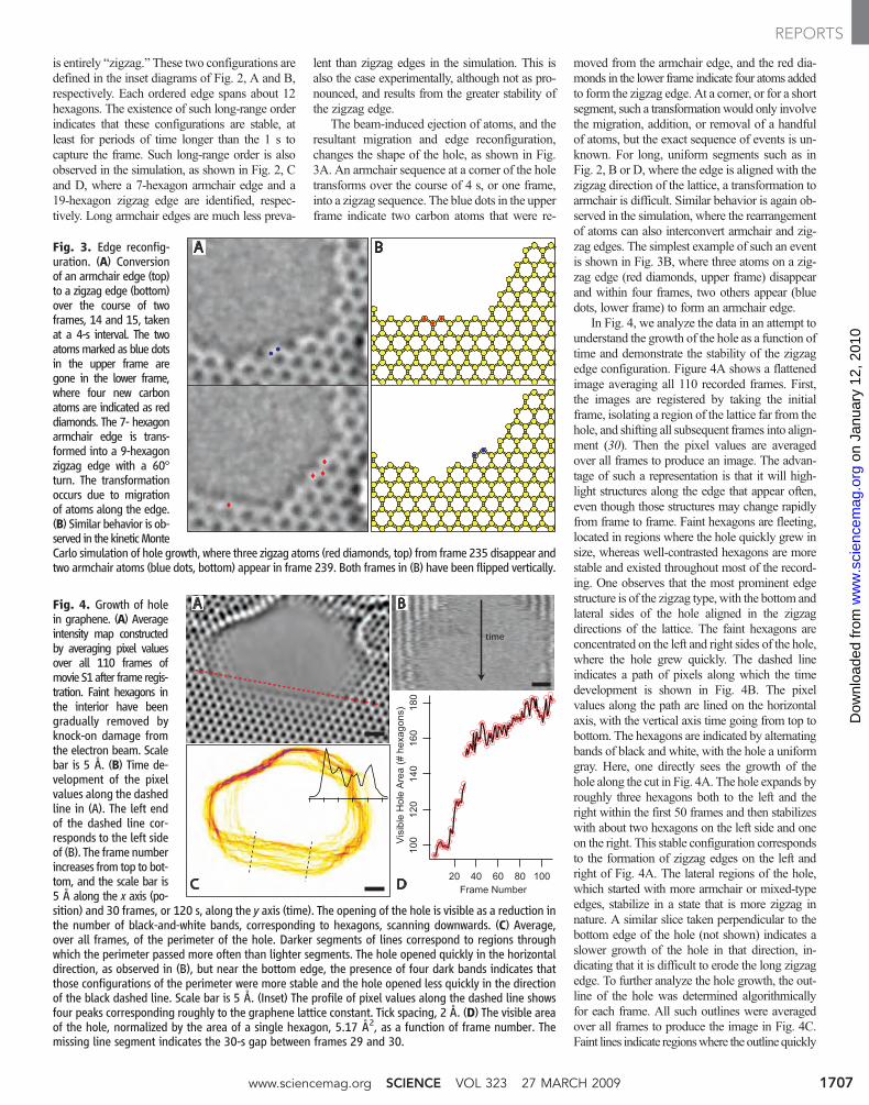
is entirely “zigzag.” These two configurations aredefined in the inset diagrams of Fig. 2, A and B,respectively. Each ordered edge spans about 12hexagons. The existence of such long-range orderindicates that these configurations are stable, atleast for periods of time longer than the 1 s tocapture the frame. Such long-range order is alsoobserved in the simulation, as shown in Fig. 2, Cand D, where a 7-hexagon armchair edge and a19-hexagon zigzag edge are identified, respec-tively. Long armchair edges are much less preva-
lent than zigzag edges in the simulation. This isalso the case experimentally, although not as pro-nounced, and results from the greater stability ofthe zigzag edge.
The beam-induced ejection of atoms, and theresultant migration and edge reconfiguration,changes the shape of the hole, as shown in Fig.3A. An armchair sequence at a corner of the holetransforms over the course of 4 s, or one frame,into a zigzag sequence. The blue dots in the upperframe indicate two carbon atoms that were re-
moved from the armchair edge, and the red dia-monds in the lower frame indicate four atoms addedto form the zigzag edge. At a corner, or for a shortsegment, such a transformationwould only involvethe migration, addition, or removal of a handfulof atoms, but the exact sequence of events is un-known. For long, uniform segments such as inFig. 2, B or D, where the edge is aligned with thezigzag direction of the lattice, a transformation toarmchair is difficult. Similar behavior is again ob-served in the simulation, where the rearrangementof atoms can also interconvert armchair and zig-zag edges. The simplest example of such an eventis shown in Fig. 3B, where three atoms on a zig-zag edge (red diamonds, upper frame) disappearand within four frames, two others appear (bluedots, lower frame) to form an armchair edge.
In Fig. 4, we analyze the data in an attempt tounderstand the growth of the hole as a function oftime and demonstrate the stability of the zigzagedge configuration. Figure 4A shows a flattenedimage averaging all 110 recorded frames. First,the images are registered by taking the initialframe, isolating a region of the lattice far from thehole, and shifting all subsequent frames into align-ment (30). Then the pixel values are averagedover all frames to produce an image. The advan-tage of such a representation is that it will high-light structures along the edge that appear often,even though those structures may change rapidlyfrom frame to frame. Faint hexagons are fleeting,located in regions where the hole quickly grew insize, whereas well-contrasted hexagons are morestable and existed throughout most of the record-ing. One observes that the most prominent edgestructure is of the zigzag type, with the bottom andlateral sides of the hole aligned in the zigzagdirections of the lattice. The faint hexagons areconcentrated on the left and right sides of the hole,where the hole grew quickly. The dashed lineindicates a path of pixels along which the timedevelopment is shown in Fig. 4B. The pixelvalues along the path are lined on the horizontalaxis, with the vertical axis time going from top tobottom. The hexagons are indicated by alternatingbands of black and white, with the hole a uniformgray. Here, one directly sees the growth of thehole along the cut in Fig. 4A. The hole expands byroughly three hexagons both to the left and theright within the first 50 frames and then stabilizeswith about two hexagons on the left side and oneon the right. This stable configuration correspondsto the formation of zigzag edges on the left andright of Fig. 4A. The lateral regions of the hole,which started with more armchair or mixed-typeedges, stabilize in a state that is more zigzag innature. A similar slice taken perpendicular to thebottom edge of the hole (not shown) indicates aslower growth of the hole in that direction, in-dicating that it is difficult to erode the long zigzagedge. To further analyze the hole growth, the out-line of the hole was determined algorithmicallyfor each frame. All such outlines were averagedover all frames to produce the image in Fig. 4C.Faint lines indicate regionswhere the outline quickly
Fig. 3. Edge reconfig-uration. (A) Conversionof an armchair edge (top)to a zigzag edge (bottom)over the course of twoframes, 14 and 15, takenat a 4-s interval. The twoatomsmarked as blue dotsin the upper frame aregone in the lower frame,where four new carbonatoms are indicated as reddiamonds. The 7- hexagonarmchair edge is trans-formed into a 9-hexagonzigzag edge with a 60°turn. The transformationoccurs due to migrationof atoms along the edge.(B) Similar behavior is ob-served in the kineticMonteCarlo simulation of hole growth, where three zigzag atoms (red diamonds, top) from frame 235 disappear andtwo armchair atoms (blue dots, bottom) appear in frame 239. Both frames in (B) have been flipped vertically.
Fig. 4. Growth of holein graphene. (A) Averageintensity map constructedby averaging pixel valuesover all 110 frames ofmovie S1after frame regis-tration. Faint hexagons inthe interior have beengradually removed byknock-on damage fromthe electron beam. Scalebar is 5 Å. (B) Time de-velopment of the pixelvalues along the dashedline in (A). The left endof the dashed line cor-responds to the left sideof (B). The frame numberincreases from top to bot-tom, and the scale bar is5 Å along the x axis (po-sition) and 30 frames, or 120 s, along the y axis (time). The opening of the hole is visible as a reduction inthe number of black-and-white bands, corresponding to hexagons, scanning downwards. (C) Average,over all frames, of the perimeter of the hole. Darker segments of lines correspond to regions throughwhich the perimeter passed more often than lighter segments. The hole opened quickly in the horizontaldirection, as observed in (B), but near the bottom edge, the presence of four dark bands indicates thatthose configurations of the perimeter were more stable and the hole opened less quickly in the directionof the black dashed line. Scale bar is 5 Å. (Inset) The profile of pixel values along the dashed line showsfour peaks corresponding roughly to the graphene lattice constant. Tick spacing, 2 Å. (D) The visible areaof the hole, normalized by the area of a single hexagon, 5.17 Å2, as a function of frame number. Themissing line segment indicates the 30-s gap between frames 29 and 30.
www.sciencemag.org SCIENCE VOL 323 27 MARCH 2009 1707
REPORTS
on
Janu
ary
12, 2
010
ww
w.s
cien
cem
ag.o
rgD
ownl
oade
d fr
om

changed shape and darker ones where the outlineof the hole was more constant. The analysis ofthe lateral and bottom regions is similar to theabove, except that one clearly sees four bands onthe bottom (between dashed lines) aligned alongthe zigzag direction. This indicates once morethat the hole was more stable along that directionand that the hexagons remained in place longer.An averaged line profile over those bands showsfour peaks (inset, Fig. 4C), with a mean spacingof 2.1 Å, close to the lattice constant of 2.46 Å.Finally, in Fig. 4D, the area within the hole, asdetermined from the outlines, is computed andplotted as a function of frame number. We see thesharp increase in area within the first 50 frames asthe hexagons along the left and right edges of thehole are removed, and then the hole growth slowsdown as a more stable configuration and a largerhole is produced. This global analysis of the edgestability is complemented by a site-by-site analy-sis of the zigzag fraction (fig. S1).
A simple model can account for the stabilityof zigzag edges observed in both experiment andsimulation by considering the effect of ejectingan atom at the edge for each chirality (fig. S2).Half of the atoms along a zigzag or armchair edgeare bonded to two neighboring atoms, and theother half are bonded to three neighboring atoms.Naively, we expect that the atoms most likely tobe ejected by the electron beam are those withtwo neighboring atoms. The removal of such anatom from a zigzag edge leaves a vacancy with-out creating any dangling carbon atoms, thosebonded to only a single neighbor. However theremoval of such an atom from an armchair edgedoes leave a dangling carbon atom, which caneasily migrate and fill a vacancy elsewhere on theedge, as the calculations predict (30). For an arm-chair configuration, two atoms are needed to repairthe edge: the atom that was ejected and the neigh-boring dangling atom that migrated away. In azigzag edge, only the ejected atom needs replace-ment. Hence, the zigzag edge is more stable underelectron irradiation at this energy, and the argu-ment holds even when the ejection of atoms alongthe edge with three neighbors is considered.
The images, simulation, and analysis presentedhere show the complicated dynamics that occurat the atomic edge of a single-layer graphene sheet.The TEAM microscope provides real-time atomicresolution, and the electron beam at 80 keVacts asan energy bath that allows the dynamics of edgereconstruction and hole growth to be observed. Inour study of the edge configuration, we demonstratethe stability of the armchair and zigzag arrangementsand quantify their evolutionwith time. Although thereconfiguration occurs on a time scale on the orderof seconds, with a comparable contribution of arm-chair and zigzag sites, the long-term stability ofzigzag edges is elucidated through a time-averageanalysis and explained by a simple model.
References and Notes1. K. S. Novoselov et al., Science 306, 666 (2004).2. J. C. Meyer et al., Nature 446, 60 (2007).
3. K. S. Novoselov et al., Proc. Natl. Acad. Sci. U.S.A. 102,10451 (2005).
4. A. K. Geim, K. S. Novoselov, Nat. Mater. 6, 183 (2007).5. K. S. Novoselov et al., Nature 438, 197 (2005).6. Y. Zhang, Y.-W. Tan, H. L. Stormer, P. Kim, Nature 438,
201 (2005).7. Y. Zhang et al., Nat. Phys. 4, 627 (2008).8. S. Y. Zhou et al., Nat. Phys. 2, 595 (2006).9. T. Ohta, A. Bostwick, T. Seyller, K. Horn, E. Rotenberg,
Science 313, 951 (2006).10. J. S. Bunch et al., Science 315, 490 (2007).11. C. Lee, X. Wei, J. W. Kysar, J. Hone, Science 321, 385
(2008).12. L. Yang, C.-H. Park, Y.-W. Son, M. L. Cohen, S. G. Louie,
Phys. Rev. Lett. 99, 186801 (2007).13. Y.-W. Son, M. L. Cohen, S. G. Louie, Nature 444, 347
(2006).14. V. W. Brar et al., Appl. Phys. Lett. 91, 122102 (2007).15. G. M. Rutter et al., Science 317, 219 (2007).16. M. Ishigami, J. H. Chen, W. G. Cullen, M. S. Fuhrer,
E. D. Williams, Nano Lett. 7, 1643 (2007).17. L. Tapaszto, G. Dobrik, P. Lambin, L. P. Biro, Nat. Nano.
3, 397 (2008).18. A. V. Martin, K. Ishizuka, C. Kisielowski, L. J. Allen, Phys.
Rev. B 74, 172102 (2006).19. J. C. Meyer, C. O. Girit, M. F. Crommie, A. Zettl, Nature
454, 319 (2008).20. J. Campos-Delgado et al., Nano Lett. 8, 2773 (2008).21. M. H. Gass et al., Nat. Nano. 3, 676 (2008).22. C. Kisielowski et al., Microsc. Microanal. 14, 454
(2008).23. J. C. Meyer et al., Nano Lett. 8, 3582 (2008).24. J. C. Meyer, C. O. Girit, M. F. Crommie, A. Zettl,
Appl. Phys. Lett. 92, 123110 (2008).25. K. W. Urban, Science 321, 506 (2008).
26. Materials and methods are available as supportingmaterial on Science Online.
27. R. F. Egerton, F. Wang, P. A. Crozier, Microsc. Microanal.12, 65 (2006).
28. B. W. Smith, D. E. Luzzi, J. Appl. Phys. 90, 3509 (2001).29. V. H. Crespi, N. G. Chopra, M. L. Cohen, A. Zettl,
S. G. Louie, Phys. Rev. B 54, 5927 (1996).30. A. F. Voter, in Proceedings of the NATO Advanced Study
Institute on Radiation Effects in Solids (Springer, Berlin,2006), pp. 1–23.
31. The National Center for Electron Microscopy issupported by the Department of Energy under contractDE-AC02-05CH11231. The TEAM project is supported bythe Department of Energy, Office of Science, Office ofBasic Energy Sciences. Ç.G., J.M., and A.Z. were supportedby the Director, Office of Energy Research, Office of BasicEnergy Sciences, Materials Sciences, and EngineeringDivision, of the U.S. Department of Energy under contractDE-AC02-05CH11231, through the sp2-bondednanostructures program. L.Y., C.-H.P., M.L.C., and S.G.L.were supported by the National Science Foundation andby the Director, Office of Science, Office of Basic EnergyScience, Division of Material Sciences and Engineering,U.S. Department of Energy. Ç.G. thanks P. Vollhardt,V. W. Brar, and Y. Zhang for interesting discussions.
Supporting Online Materialwww.sciencemag.org/cgi/content/full/323/5922/1705/DC1Materials and MethodsFigs. S1 and S2ReferencesMovies S1 and S2
9 October 2008; accepted 30 January 200910.1126/science.1166999
Reversible Interactions withpara-Hydrogen Enhance NMRSensitivity by Polarization TransferRalph W. Adams,1 Juan A. Aguilar,1 Kevin D. Atkinson,1 Michael J. Cowley,1Paul I. P. Elliott,1* Simon B. Duckett,1† Gary G. R. Green,2 Iman G. Khazal,1Joaquín López-Serrano,1 David C. Williamson1
The sensitivity of both nuclear magnetic resonance spectroscopy and magnetic resonanceimaging is very low because the detected signal strength depends on the small populationdifference between spin states even in high magnetic fields. Hyperpolarization methods can beused to increase this difference and thereby enhance signal strength. This has been achievedpreviously by incorporating the molecular spin singlet para-hydrogen into hydrogenationreaction products. We show here that a metal complex can facilitate the reversible interaction ofpara-hydrogen with a suitable organic substrate such that up to an 800-fold increase in proton,carbon, and nitrogen signal strengths are seen for the substrate without its hydrogenation.These polarized signals can be selectively detected when combined with methods that suppressbackground signals.
The wide variety of applications of nuclearmagnetic resonance (NMR) (1–3) arelimited by the technique’s extremely low
inherent sensitivity. Here we describe an approachthat uses hyperpolarized spins derived from para-hydrogen (para-H2) (4) to sensitize the NMRexperiment without actually incorporating para-H2
into the molecule that is to be probed. Specifically,we show that high-resolution NMR spectra canbe collected for a range of molecules and nucleiwith detected signal strengths up to 800 times
greater than would be normally achievable withan unpolarized sample. This improvement facil-itates the collection of diagnostic high-resolution1H, 13C, 15N, and 19F NMR spectra and magneticresonance images of selected signals in a fractionof the time that would normally be necessary.When optimized, this route is predicted to increaseproton sensitivity by up to four orders of magni-tude (5) such that the routine single shot character-ization of materials, even at picomole levels, willbecome possible (6).
27 MARCH 2009 VOL 323 SCIENCE www.sciencemag.org1708
REPORTS
on
Janu
ary
12, 2
010
ww
w.s
cien
cem
ag.o
rgD
ownl
oade
d fr
om