Embed Size (px)
Citation preview
AC
I 318
M-1
4Building Code Requirements for Structural Concrete (ACI 318M-14) and Commentary (ACI 318RM-14)Reported by ACI Committee 318
An ACI Standard

Building Code Requirements for Structural Concrete (ACI 318M-14)
An ACI Standard
Commentary on Building Code Requirements for Structural Concrete (ACI 318RM-14)
An ACI Report
Reported by ACI Committee 318
Randall W. Poston, Chair Basile G. Rabbat, Secretary
VOTING MAIN COMMITTEE MEMBERS
Neal S. AndersonFlorian G. BarthRoger J. Becker
Kenneth B. BondyDean A. BrowningJames R. CagleyNed M. Cleland
W. Gene Corley*Ronald A. Cook
Charles W. Dolan
Anthony E. FioratoCatherine E. French
Robert J. FroschLuis E. Garcia
Brian C. GerberS. K. Ghosh
David P. GustafsonJames R. Harris
Terence C. HollandShyh-Jiann Hwang
James O. JirsaDominic J. Kelly
Gary J. KleinRonald KlemencicCary Kopczynski
Colin L. LoboPaul F. MlakarJack P. Moehle
Lawrence C. NovakGustavo J. Parra-Montesinos
David M. RogowskyDavid H. SandersGuillermo Santana
Thomas C. SchaefferStephen J. SeguirantAndrew W. Taylor
James K. WightSharon L. Wood
Loring A. Wyllie Jr.
VOTING SUBCOMMITTEE MEMBERS
Raul D. BerteroAllan P. BommerJohn F. BonacciPatricio BonelliSergio F. Breña
JoAnn P. BrowningNicholas J. Carino
David DarwinJeffrey J. DragovichKenneth J. ElwoodLisa R. Feldman
Harry A. GleichH. R. Trey Hamilton
R. Doug HootonKenneth C. Hover
Steven H. KosmatkaMichael E. Kreger
Jason J. KrohnDaniel A. Kuchma
Andres LepageRaymond LuiLeRoy A. Lutz
Joe MaffeiDonald F. Meinheit
Fred MeyerSuzanne Dow Nakaki
Theodore L. NeffViral B. Patel
Conrad PaulsonJose A. Pincheira
Carin L. Roberts-WollmannMario E. Rodríguez
Bruce W. Russell
M. Saiid SaiidiAndrea J. Schokker
John F. SilvaJohn F. StantonRoberto Stark
Bruce A. SuprenantJohn W. WallaceW. Jason Weiss
Fernando V. Yáñez
INTERNATIONAL LIAISON MEMBERS
F. Michael BartlettMathias BrewerJosef Farbiarz
Luis B. Fargier-GabaldonAlberto Giovambattista
Hector Hernandez
Angel E. HerreraHector Monzon-Despang
Enrique Pasquel
Patricio A. PlacenciaOscar M. Ramirez
Fernando Reboucas Stucchi
CONSULTING MEMBERS
Sergio M. AlcocerJohn E. Breen
Neil M. HawkinsH. S. Lew
James G. MacGregorRobert F. Mast
Julio A. RamirezCharles G. Salmon*
ACI 318M-14 supersedes ACI 318M-11, and published March 2015.Copyright © 2015, American Concrete Institute.
All rights reserved including rights of reproduction and use in any form or by any means, including the making of copies by any photo process, or by electronic or mechanical device, printed, written, or oral, or recording for sound or visual reproduc-tion or for use in any knowledge or retrieval system or device, unless permission in writing is obtained from the copyright proprietors.
1
*Deceased.

First PrintingMarch 2015
ISBN: 978-1-942727-11-8
Building Code Requirements for Structural Concrete and Commentary
Copyright by the American Concrete Institute, Farmington Hills, MI. All rights reserved. This material may not be reproduced or copied, in whole or part, in any printed, mechanical, electronic, film, or other distribution and storage media, without the written consent of ACI.
The technical committees responsible for ACI committee reports and standards strive to avoid ambiguities, omissions, and errors in these documents. In spite of these efforts, the users of ACI documents occasionally find information or requirements that may be subject to more than one interpretation or may be incomplete or incorrect. Users who have suggestions for the improvement of ACI documents are requested to contact ACI via the errata website at http://concrete.org/Publications/DocumentErrata.aspx. Proper use of this document includes periodically checking for errata for the most up-to-date revisions.
ACI committee documents are intended for the use of individuals who are competent to evaluate the significance and limitations of its content and recommendations and who will accept responsibility for the application of the material it contains. Individuals who use this publication in any way assume all risk and accept total responsibility for the application and use of this information.
All information in this publication is provided “as is” without warranty of any kind, either express or implied, including but not limited to, the implied warranties of merchantability, fitness for a particular purpose or non-infringement.
ACI and its members disclaim liability for damages of any kind, including any special, indirect, incidental, or consequential damages, including without limitation, lost revenues or lost profits, which may result from the use of this publication.
It is the responsibility of the user of this document to establish health and safety practices appropriate to the specific circumstances involved with its use. ACI does not make any representations with regard to health and safety issues and the use of this document. The user must determine the applicability of all regulatory limitations before applying the document and must comply with all applicable laws and regulations, including but not limited to, United States Occupational Safety and Health Administration (OSHA) health and safety standards.
Participation by governmental representatives in the work of the American Concrete Institute and in the development of Institute standards does not constitute governmental endorsement of ACI or the standards that it develops.
Order information: ACI documents are available in print, by download, on CD-ROM, through electronic subscription, or reprint and may be obtained by contacting ACI.
Most ACI standards and committee reports are gathered together in the annually revised ACI Manual of Concrete Practice (MCP).
American Concrete Institute38800 Country Club DriveFarmington Hills, MI 48331Phone: +1.248.848.3700Fax: +1.248.848.3701
www.concrete.org
PREFACE TO ACI 318M-14The “Building Code Requirements for Structural Concrete” (“Code”) provides minimum requirements for the materials,
design, and detailing of structural concrete buildings and, where applicable, nonbuilding structures. This Code addresses struc-tural systems, members, and connections, including cast-in-place, precast, plain, nonprestressed, prestressed, and composite construction. Among the subjects covered are: design and construction for strength, serviceability, and durability; load combi-nations, load factors, and strength reduction factors; structural analysis methods; deflection limits; mechanical and adhesive anchoring to concrete; development and splicing of reinforcement; construction document information; field inspection and testing; and methods to evaluate the strength of existing structures. “Building Code Requirements for Concrete Thin Shells” (ACI 318.2) is adopted by reference in this Code.
The Code user will find that ACI 318-14 has been substantially reorganized and reformatted from previous editions. The principal objectives of this reorganization are to present all design and detailing requirements for structural systems or for indi-vidual members in chapters devoted to those individual subjects, and to arrange the chapters in a manner that generally follows the process and chronology of design and construction. Information and procedures that are common to the design of members are located in utility chapters.
The quality and testing of materials used in construction are covered by reference to the appropriate ASTM standard speci-fications. Welding of reinforcement is covered by reference to the appropriate American Welding Society (AWS) standard.
Uses of the Code include adoption by reference in a general building code, and earlier editions have been widely used in this manner. The Code is written in a format that allows such reference without change to its language. Therefore, background details or suggestions for carrying out the requirements or intent of the Code provisions cannot be included within the Code itself. The Commentary is provided for this purpose.
Some of the considerations of the committee in developing the Code are discussed within the Commentary, with emphasis given to the explanation of new or revised provisions. Much of the research data referenced in preparing the Code is cited for the user desiring to study individual questions in greater detail. Other documents that provide suggestions for carrying out the requirements of the Code are also cited.
Technical changes from ACI 318-11 to ACI 318-14 are outlined in the May 2014 issue of Concrete International.Transition keys showing how the code was reorganized are provided on the ACI website on the 318 Resource Page under
Topics in Concrete.
KEYWORDSadmixtures; aggregates; anchorage (structural); beam-column frame; beams (supports); building codes; cements; cold
weather construction; columns (supports); combined stress; composite construction (concrete and steel); composite construc-tion (concrete to concrete); compressive strength; concrete construction; concrete slabs; concretes; construction joints; conti-nuity (structural); construction documents; contraction joints; cover; curing; deep beams; deflections; earthquake-resistant structures; embedded service ducts; flexural strength; floors; folded plates; footings; formwork (construction); frames; hot weather construction; inspection; isolation joints; joints (junctions); joists; lightweight concretes; load tests (structural); loads (forces); materials; mixing; mixture proportioning; modulus of elasticity; moments; pipe columns; pipes (tubing); placing; plain concrete; precast concrete; prestressed concrete; prestressing steels; quality control; reinforced concrete; reinforcing steels; roofs; serviceability; shear strength; shear walls; shells (structural forms); spans; splicing; strength; strength analysis; stresses; structural analysis; structural concrete; structural design; structural integrity; T-beams; torsion; walls; water; welded wire reinforcement.
NOTES FROM THE PUBLISHERACI Committee Reports, Guides, and Commentaries are intended for guidance in planning, designing, executing, and
inspecting construction. This commentary (318RM-14) is intended for the use of individuals who are competent to evaluate the significance and limitations of its content and recommendations and who will accept responsibility for the application of the information it contains. ACI disclaims any and all responsibility for the stated principles. The Institute shall not be liable for any loss or damage arising there from. Reference to this commentary shall not be made in construction documents. If items found in this commentary are desired by the Architect/ Engineer to be a part of the construction documents, they shall be restated in mandatory language for incorporation by the Architect/Engineer.
The materials, processes, quality control measures, and inspections described in this document should be tested, monitored, or performed as applicable only by individuals holding the appropriate ACI Certification or equivalent.
ACI 318M-14, Building Code Requirements for Structural Concrete, and ACI 318RM-14, Commentary, are presented in a side-by-side column format. These are two separate but coordinated documents, with Code text placed in the left column and the corresponding Commentary text aligned in the right column. Commentary section numbers are preceded by an “R” to further distinguish them from Code section numbers.
The two documents are bound together solely for the user’s convenience. Each document carries a separate enforceable and distinct copyright.
American Concrete Institute – Copyrighted © Material – www.concrete.org
BUILDING CODE REQUIREMENTS FOR STRUCTURAL CONCRETE (ACI 318M-14) AND COMMENTARY (ACI 318RM-14) 3
INTRODUCTION
This Commentary discusses some of the considerations of Committee 318 in developing the provisions contained in “Building Code Requirements for Structural Concrete (ACI 318-14),” hereinafter called the Code or the 2014 Code. Emphasis is given to the explanation of new or revised provisions that may be unfamiliar to Code users. In addition, comments are included for some items contained in previous editions of the Code to make the present commentary inde-pendent of the previous editions. Comments on specific provisions are made under the corresponding chapter and section numbers of the Code.
The Commentary is not intended to provide a complete historical background concerning the development of the Code, nor is it intended to provide a detailed résumé of the studies and research data reviewed by the committee in formulating the provisions of the Code. However, references to some of the research data are provided for those who wish to study the background material in depth.
As the name implies, “Building Code Requirements for Structural Concrete” is meant to be used as part of a legally adopted building code and as such must differ in form and substance from documents that provide detailed specifica-tions, recommended practice, complete design procedures, or design aids.
The Code is intended to cover all buildings of the usual types, both large and small. Requirements more stringent than the Code provisions may be desirable for unusual construction. The Code and Commentary cannot replace sound engineering knowledge, experience, and judgment.
A building code states only the minimum requirements necessary to provide for public health and safety. The Code is based on this principle. For any structure, the owner or the licensed design professional may require the quality of materials and construction to be higher than the minimum requirements necessary to protect the public as stated in the Code. However, lower standards are not permitted.
The Commentary directs attention to other documents that provide suggestions for carrying out the requirements and intent of the Code. However, those documents and the Commentary are not a part of the Code.
The Code has no legal status unless it is adopted by the government bodies having the police power to regulate building design and construction. Where the Code has not been adopted, it may serve as a reference to good practice even though it has no legal status.
The Code provides a means of establishing minimum standards for acceptance of designs and construction by legally appointed building officials or their designated repre-sentatives. The Code and Commentary are not intended for
use in settling disputes between the owner, engineer, archi-tect, contractor, or their agents, subcontractors, material suppliers, or testing agencies. Therefore, the Code cannot define the contract responsibility of each of the parties in usual construction. General references requiring compli-ance with the Code in the project specifications should be avoided since the contractor is rarely in a position to accept responsibility for design details or construction require-ments that depend on a detailed knowledge of the design. Design-build construction contractors, however, typically combine the design and construction responsibility. Gener-ally, the contract documents should contain all of the neces-sary requirements to ensure compliance with the Code. In part, this can be accomplished by reference to specific Code sections in the project specifications. Other ACI publica-tions, such as “Specifications for Structural Concrete (ACI 301)” are written specifically for use as contract documents for construction.
It is recommended to have testing and certification programs for the individual parties involved with the execu-tion of work performed in accordance with this Code. Avail-able for this purpose are the plant certification programs of the Precast/Prestressed Concrete Institute, the Post-Tensioning Institute, and the National Ready Mixed Concrete Associa-tion; the personnel certification programs of the American Concrete Institute and the Post-Tensioning Institute; and the Concrete Reinforcing Steel Institute’s Voluntary Certifica-tion Program for Fusion-Bonded Epoxy Coating Applicator Plants. In addition, “Standard Specification for Agencies Engaged in Construction Inspecting and/or Testing” (ASTM E329-09) specifies performance requirements for inspection and testing agencies.
Design reference materials illustrating applications of the Code requirements may be found in the following docu-ments. The design aids listed may be obtained from the sponsoring organization.
Design aids:“ACI Design Handbook,” Publication SP-17(11), Amer-
ican Concrete Institute, Farmington Hills, MI, 2011, 539 pp. (This provides tables and charts for design of eccentrically loaded columns by the Strength Design Method of the 2009 Code. Provides design aids for use in the engineering design and analysis of reinforced concrete slab systems carrying loads by two-way action. Design aids are also provided for the selection of slab thickness and for reinforcement required to control deformation and assure adequate shear and flexural strengths.)
For a history of the ACI Building Code, see Kerekes, F., and Reid, H. B., Jr., “Fifty Years of Development in Building Code Requirements for Reinforced Concrete,” ACI Journal, V. 50, No. 6, Feb. 1954, p. 441. For a discussion of code philosophy, see Siess, C. P., “Research, Building Codes, and Engineering Practice,” ACI Journal, V. 56, No. 5, May 1960, p. 1105.
American Concrete Institute – Copyrighted © Material – www.concrete.org
4 BUILDING CODE REQUIREMENTS FOR STRUCTURAL CONCRETE (ACI 318M-14) AND COMMENTARY (ACI 318RM-14)
“ACI Detailing Manual—2004,” ACI Committee 315, Publication SP-66(04), American Concrete Institute, Farm-ington Hills, MI, 2004, 212 pp. (Includes the standard, ACI 315-99, and report, ACI 315R-04. Provides recommended methods and standards for preparing engineering drawings, typical details, and drawings placing reinforcing steel in rein-forced concrete structures. Separate sections define respon-sibilities of both engineer and reinforcing bar detailer.)
“Guide to Durable Concrete (ACI 201.2R-08),” ACI Committee 201, American Concrete Institute, Farmington Hills, MI, 2008, 49 pp. (This describes specific types of concrete deterioration. It contains a discussion of the mech-anisms involved in deterioration and the recommended requirements for individual components of the concrete, quality considerations for concrete mixtures, construction procedures, and influences of the exposure environment.)
“Guide for the Design and Construction of Durable Parking Structures (362.1R-12),” ACI Committee 362, American Concrete Institute, Farmington Hills, MI, 2012, 24 pp. (This summarizes practical information regarding design of parking structures for durability. It also includes information about design issues related to parking structure construction and maintenance.)
“CRSI Handbook,” Concrete Reinforcing Steel Institute, Schaumburg, IL, tenth edition, 2008, 777 pp. (This provides tabulated designs for structural elements and slab systems. Design examples are provided to show the basis and use of the load tables. Tabulated designs are given for beams; square, round, and rectangular columns; one-way slabs; and one-way joist construction. The design tables for two-way slab systems include flat plates, flat slabs, and waffle slabs. The chapters on foundations provide design tables for square footings, pile caps, drilled piers (caissons), and cantilevered retaining walls. Other design aids are presented for crack control and development of reinforcement and lap splices.)
“Reinforcement Anchorages and Splices,” Concrete Reinforcing Steel Institute, Schaumburg, IL, fifth edition, 2008, 100 pp. (This provides accepted practices in splicing reinforcement. The use of lap splices, mechanical splices,
and welded splices are described. Design data are presented for development and lap splicing of reinforcement.)
“Structural Welded Wire Reinforcement Manual of Standard Practice,” Wire Reinforcement Institute, Hart-ford, CT, eighth edition, Apr. 2010, 35 pp. (This describes welded wire reinforcement material, gives nomenclature and wire size and weight tables. Lists specifications and prop-erties and manufacturing limitations. Book has latest code requirements as code affects welded wire. Also gives devel-opment length and splice length tables. Manual contains customary units and soft metric units.)
“Structural Welded Wire Reinforcement Detailing Manual,” Wire Reinforcement Institute, Hartford, CT, 1994, 252 pp. (The manual, in addition to including ACI 318 provisions and design aids, also includes: detailing guid-ance on welded wire reinforcement in one-way and two-way slabs; precast/prestressed concrete components; columns and beams; cast-in-place walls; and slabs-on-ground. In addition, there are tables to compare areas and spacings of high-strength welded wire with conventional reinforcing.)
“PCI Design Handbook—Precast and Prestressed Concrete,” Precast/Prestressed Concrete Institute, Chicago, IL, seventh edition, 2010, 804 pp. (This provides load tables for common industry products, and procedures for design and analysis of precast and prestressed elements and struc-tures composed of these elements. Provides design aids and examples.)
“Design and Typical Details of Connections for Precast and Prestressed Concrete,” Precast/Prestressed Concrete Institute, Chicago, IL, second edition, 1988, 270 pp. (This updates available information on design of connections for both structural and architectural products, and presents a full spectrum of typical details. This provides design aids and examples.)
“Post-Tensioning Manual,” Post-Tensioning Insti-tute, Farmington Hills, MI, sixth edition, 2006, 354 pp. (This provides comprehensive coverage of post-tensioning systems, specifications, design aids, and construction concepts.)
American Concrete Institute – Copyrighted © Material – www.concrete.org
BUILDING CODE REQUIREMENTS FOR STRUCTURAL CONCRETE (ACI 318M-14) AND COMMENTARY (ACI 318RM-14) 5
TABLE OF CONTENTS
PART 1: GENERAL
CHAPTER 1 GENERAL
1.1—Scope of ACI 318, p. 91.2—General, p. 91.3—Purpose, p. 101.4—Applicability, p. 101.5—Interpretation, p. 111.6—Building official, p. 121.7—Licensed design professional, p. 131.8—Construction documents and design records, p. 131.9—Testing and inspection, p. 131.10—Approval of special systems of design, construction,
or alternative construction materials, p. 13
CHAPTER 2 NOTATION AND TERMINOLOGY
2.1—Scope, p. 152.2—Notation, p. 152.3—Terminology, p. 30
CHAPTER 3 REFERENCED STANDARDS
3.1—Scope, p. 453.2—Referenced standards, p. 45
CHAPTER 4 STRUCTURAL SYSTEM REQUIREMENTS
4.1—Scope ,p. 494.2—Materials, p. 494.3—Design loads, p. 494.4—Structural system and load paths, p. 494.5—Structural analysis, p. 524.6—Strength, p. 524.7—Serviceability, p. 534.8—Durability, p. 534.9—Sustainability, p. 534.10—Structural integrity, p. 544.11—Fire resistance, p. 544.12—Requirements for specific types of construction,
p. 544.13—Construction and inspection, p. 564.14—Strength evaluation of existing structures, p. 56
PART 2: LOADS & ANALYSIS
CHAPTER 5 LOADS
5.1—Scope, p. 575.2—General, p. 575.3—Load factors and combinations, p. 58
CHAPTER 6 STRUCTURAL ANALYSIS
6.1—Scope, p. 636.2—General, p. 636.3—Modeling assumptions, p. 686.4—Arrangement of live load, p. 696.5—Simplified method of analysis for nonprestressed
continuous beams and one-way slabs, p. 706.6—First-order analysis, p. 716.7—Elastic second-order analysis, p. 796.8—Inelastic second-order analysis, p. 816.9—Acceptability of finite element analysis, p. 81
PART 3: MEMBERS
CHAPTER 7 ONE-WAY SLABS
7.1—Scope, p. 837.2—General, p. 837.3—Design limits, p. 837.4—Required strength, p. 857.5—Design strength, p. 857.6—Reinforcement limits, p. 867.7—Reinforcement detailing, p. 88
CHAPTER 8 TWO-WAY SLABS
8.1—Scope, p. 938.2—General, p. 938.3—Design limits, p. 948.4—Required strength, p. 978.5—Design strength, p. 1028.6—Reinforcement limits, p. 1038.7—Reinforcement detailing, p. 1068.8—Nonprestressed two-way joist systems, p. 1178.9—Lift-slab construction, p. 1188.10—Direct design method, p. 1188.11—Equivalent frame method, p. 124
CHAPTER 9 BEAMS
9.1—Scope, p. 1299.2—General, p. 1299.3—Design limits, p. 1309.4—Required strength, p. 1329.5—Design strength, p. 1349.6—Reinforcement limits, p. 1369.7—Reinforcement detailing, p. 1409.8—Nonprestressed one-way joist systems, p. 1499.9—Deep beams, p. 151
CHAPTER 10 COLUMNS
10.1—Scope, p. 15310.2—General, p. 15310.3—Design limits, p. 153
American Concrete Institute – Copyrighted © Material – www.concrete.org
6 BUILDING CODE REQUIREMENTS FOR STRUCTURAL CONCRETE (ACI 318M-14) AND COMMENTARY (ACI 318RM-14)
10.4—Required strength, p. 15410.5—Design strength, p. 15510.6—Reinforcement limits, p. 15610.7—Reinforcement detailing, p. 157
CHAPTER 11 WALLS
11.1—Scope, p. 16311.2—General, p. 16311.3—Design limits, p. 16411.4—Required strength, p. 16411.5—Design strength, p. 16511.6—Reinforcement limits, p. 16811.7—Reinforcement detailing, p. 16911.8—Alternative method for out-of-plane slender wall
analysis, p. 171
CHAPTER 12 DIAPHRAGMS
12.1—Scope, p. 17312.2—General, p. 17312.3—Design limits, p. 17512.4—Required strength, p. 17512.5—Design strength, p. 17812.6—Reinforcement limits, p. 18512.7—Reinforcement detailing, p. 185
CHAPTER 13 FOUNDATIONS
13.1—Scope, p. 18713.2—General, p. 18913.3—Shallow foundations, p. 19213.4—Deep foundations, p. 193
CHAPTER 14 PLAIN CONCRETE
14.1—Scope, p. 19514.2—General, p. 19614.3—Design limits, p. 19614.4—Required strength , p. 19814.5—Design strength, p. 19914.6—Reinforcement detailing, p. 202
PART 4: JOINTS/CONNECTIONS/ANCHORS
CHAPTER 15 BEAM-COLUMN AND SLAB-COLUMN JOINTS
15.1—Scope, p. 20315.2—General, p. 20315.3—Transfer of column axial force through the floor
system, p. 20315.4—Detailing of joints, p. 204
CHAPTER 16 CONNECTIONS BETWEEN MEMBERS
16.1—Scope, p. 20516.2—Connections of precast members, p. 20516.3—Connections to foundations, p. 209
16.4—Horizontal shear transfer in composite concrete flexural members, p. 212
16.5—Brackets and corbels, p. 214
CHAPTER 17 ANCHORING TO CONCRETE
17.1—Scope, p. 22117.2—General, p. 22217.3—General requirements for strength of anchors, p. 22817.4—Design requirements for tensile loading, p. 23417.5—Design requirements for shear loading, p. 24717.6—Interaction of tensile and shear forces, p. 25817.7—Required edge distances, spacings, and thicknesses
to preclude splitting failure, p. 25817.8—Installation and inspection of anchors, p. 260
PART 5: EARTHQUAKE RESISTANCE
CHAPTER 18 EARTHQUAKE-RESISTANT STRUCTURES
18.1—Scope, p. 26318.2—General, p. 26318.3—Ordinary moment frames, p. 26918.4—Intermediate moment frames, p. 26918.5—Intermediate precast structural walls, p. 27418.6—Beams of special moment frames, p. 27518.7—Columns of special moment frames, p. 28018.8—Joints of special moment frames, p. 28518.9—Special moment frames constructed using precast
concrete, p. 28918.10—Special structural walls, p. 29218.11—Special structural walls constructed using precast
concrete, p. 30418.12—Diaphragms and trusses, p. 30418.13—Foundations, p. 31018.14—Members not designated as part of the seismic-
force-resisting system, p. 312
PART 6: MATERIALS & DURABILITY
CHAPTER 19 CONCRETE: DESIGN AND DURABILITY REQUIREMENTS
19.1—Scope, p. 31519.2—Concrete design properties, p. 31519.3—Concrete durability requirements, p. 31619.4—Grout durability requirements, p. 324
CHAPTER 20 STEEL REINFORCEMENT PROPERTIES, DURABILITY, AND EMBEDMENTS
20.1—Scope, p. 32520.2—Nonprestressed bars and wires, p. 32520.3—Prestressing strands, wires, and bars, p. 33020.4—Structural steel, pipe, and tubing for composite
columns, p. 33320.5—Headed shear stud reinforcement, p. 334
American Concrete Institute – Copyrighted © Material – www.concrete.org
BUILDING CODE REQUIREMENTS FOR STRUCTURAL CONCRETE (ACI 318M-14) AND COMMENTARY (ACI 318RM-14) 7
20.6—Provisions for durability of steel reinforcement, p. 334
20.7—Embedments, p. 339
PART 7: STRENGTH & SERVICEABILITY
CHAPTER 21 STRENGTH REDUCTION FACTORS
21.1—Scope, p. 34121.2—Strength reduction factors for structural concrete
members and connections p. 341
CHAPTER 22 SECTIONAL STRENGTH
22.1—Scope, p. 34722.2—Design assumptions for moment and axial strength,
p. 34722.3—Flexural strength, p. 34922.4—Axial strength or combined flexural and axial
strength, p. 35022.5—One-way shear strength, p. 35122.6—Two-way shear strength, p. 36022.7—Torsional strength, p. 37122.8—Bearing, p. 37822.9—Shear friction, p. 380
CHAPTER 23 STRUT-AND-TIE MODELS
23.1—Scope, p. 38523.2—General, p. 38623.3—Design strength, p. 39223.4—Strength of struts, p. 39223.5—Reinforcement crossing bottle-shaped struts, p. 39423.6—Strut reinforcement detailing, p. 39523.7—Strength of ties, p. 39523.8—Tie reinforcement detailing, p. 39623.9—Strength of nodal zones, p. 397
CHAPTER 24 SERVICEABILITY REQUIREMENTS
24.1—Scope, p. 39924.2—Deflections due to service-level gravity loads, p. 39924.3—Distribution of flexural reinforcement in one-way
slabs and beams, p. 40324.4—Shrinkage and temperature reinforcement, p. 40524.5—Permissible stresses in prestressed concrete flexural
members, p. 407
PART 8: REINFORCEMENT
CHAPTER 25 REINFORCEMENT DETAILS
25.1—Scope, p. 41125.2—Minimum spacing of reinforcement, p. 41125.3—Standard hooks, seismic hooks, crossties, and
minimum inside bend diameters, p. 412
25.4—Development of reinforcement, p. 41425.5—Splices, p. 42825.6—Bundled reinforcement, p. 43325.7—Transverse reinforcement, p. 43425.8—Post-tensioning anchorages and couplers, p. 44325.9—Anchorage zones for post-tensioned tendons, p. 443
PART 9: CONSTRUCTION
CHAPTER 26 CONSTRUCTION DOCUMENTS AND INSPECTION
26.1—Scope, p. 45326.2—Design criteria, p. 45526.3—Member information, p. 45526.4—Concrete materials and mixture requirements, p. 45526.5—Concrete production and construction, p. 46226.6—Reinforcement materials and construction
requirements, p. 46826.7—Anchoring to concrete , p. 47226.8—Embedments, p. 47326.9—Additional requirements for precast concrete , p. 47326.10—Additional requirements for prestressed concrete,
p. 47426.11—Formwork, p. 47626.12—Concrete evaluation and acceptance, p. 47826.13—Inspection, p. 483
PART 10: EVALUATION
CHAPTER 27 STRENGTH EVALUATION OF EXISTING STRUCTURES
27.1—Scope, p. 48727.2—General, p. 48727.3—Analytical strength evaluation, p. 48827.4—Strength evaluation by load test, p. 48927.5—Reduced load rating, p. 492
REFERENCES & APPENDICES
COMMENTARY REFERENCES
APPENDIX A STEEL REINFORCEMENT INFORMATION
APPENDIX B EQUIVALENCE BETWEEN SI-METRIC, MKS-METRIC, AND U.S. CUSTOMARY UNITS OF NONHOMOGENOUS EQUATIONS IN THE CODE
INDEX
American Concrete Institute – Copyrighted © Material – www.concrete.org
8 BUILDING CODE REQUIREMENTS FOR STRUCTURAL CONCRETE (ACI 318M-14) AND COMMENTARY (ACI 318RM-14)
CHAPTER 1—GENERAL
1.1—Scope of ACI 318 1.1.1 This chapter addresses (a) through (h):
(a) General requirements of this Code(b) Purpose of this Code(c) Applicability of this Code(d) Interpretation of this Code(e) Definition and role of the building official and the licensed design professional(f) Construction documents(g) Testing and inspection(h) Approval of special systems of design, construction, or alternative construction materials
1.2—General 1.2.1 ACI 318, “Building Code Requirements for Struc-
tural Concrete,” is hereafter referred to as “this Code.”
1.2.2 In this Code, the general building code refers to the building code adopted in a jurisdiction. When adopted, this Code forms part of the general building code.
1.2.3 The official version of this Code is the English language version, using inch-pound units, published by the American Concrete Institute.
1.2.4 In case of conflict between the official version of this Code and other versions of this Code, the official version governs.
1.2.5 This Code provides minimum requirements for the materials, design, construction, and strength evaluation of structural concrete members and systems in any structure designed and constructed under the requirements of the general building code.
1.2.6 Modifications to this Code that are adopted by a particular jurisdiction are part of the laws of that jurisdic-tion, but are not a part of this Code.
1.2.7 If no general building code is adopted, this Code provides minimum requirements for the materials, design, construction, and strength evaluation of members and systems in any structure within the scope of this Code.
R1—GENERAL
R1.1—Scope of ACI 318 R1.1.1 This Code includes provisions for the design
of concrete used for structural purposes, including plain concrete; concrete containing nonprestressed reinforcement, prestressed reinforcement, or both; composite columns with structural steel shapes, pipes, or tubing; and anchoring to concrete.
This Code is substantially reorganized from the previous version, ACI 318M-11. This chapter includes a number of provisions that explain where this Code applies and how it is to be interpreted.
R1.2—General
R1.2.2 The American Concrete Institute recommends that this Code be adopted in its entirety.
R1.2.3 Committee 318 develops the Code in English, using inch-pound units. Based on that version, Committee 318 approved three other versions:
(a) In English using SI units (ACI 318M)(b) In Spanish using SI units (ACI 318S)(c) In Spanish using inch-pound units (ACI 318SUS).
Jurisdictions may adopt ACI 318, ACI 318M, ACI 318S, or ACI 318SUS.
R1.2.5 This Code provides minimum requirements and exceeding these minimum requirements is not a violation of the Code.
The licensed design professional may specify project requirements that exceed the minimum requirements of this Code.
American Concrete Institute – Copyrighted © Material – www.concrete.org
CHAPTER 1—GENERAL 9
CODE COMMENTARY
1
1.3—Purpose 1.3.1 The purpose of this Code is to provide for public
health and safety by establishing minimum requirements for strength, stability, serviceability, durability, and integrity of concrete structures.
1.3.2 This Code does not address all design considerations.
1.3.3 Construction means and methods are not addressed in this Code.
1.4—Applicability 1.4.1 This Code shall apply to concrete structures designed
and constructed under the requirements of the general building code.
1.4.2 Applicable provisions of this Code shall be permitted to be used for structures not governed by the general building code.
1.4.3 The design of thin shells and folded plate concrete structures shall be in accordance with ACI 318.2, “Building Code Requirements for Concrete Thin Shells.”
1.4.4 This Code shall apply to the design of slabs cast on stay-in-place, noncomposite steel decks.
1.4.5 For one- and two-family dwellings, multiple single-family dwellings, townhouses, and accessory structures to
R1.3—Purpose R1.3.1 This Code provides a means of establishing
minimum requirements for the design and construction of structural concrete, as well as for acceptance of design and construction of concrete structures by the building officials or their designated representatives.
This Code does not provide a comprehensive statement of all duties of all parties to a contract or all requirements of a contract for a project constructed under this Code.
R1.3.2 The minimum requirements in this Code do not replace sound professional judgment or the licensed design professional’s knowledge of the specific factors surrounding a project, its design, the project site, and other specific or unusual circumstances to the project.
R1.4—Applicability
R1.4.2 Structures such as arches, bins and silos, blast-resistant structures, chimneys, underground utility struc-tures, gravity walls, and shielding walls involve design and construction requirements that are not specifically addressed by this Code. Many Code provisions, however, such as concrete quality and design principles, are applicable for these structures. Recommendations for design and construc-tion of some of these structures are given in the following:• “Code Requirements for Reinforced Concrete Chim-
neys and Commentary” (ACI 307-08)• “Standard Practice for Design and Construction of
Concrete Silos and Stacking Tubes for Storing Granular Materials” (ACI 313-97)
• “Code Requirements for Nuclear Safety-Related Concrete Structures and Commentary” (ACI 349)
• “Code for Concrete Containments” (ACI 359)
R1.4.4 In its most basic application, the noncomposite steel deck serves as a form, and the concrete slab is designed to resist all loads, while in other applications the concrete slab may be designed to resist only the superimposed loads. The design of a steel deck in a load-resisting application is given in “Standard for Non-Composite Steel Floor Deck” (SDI NC). The SDI standard refers to this Code for the design and construction of the structural concrete slab.
R1.4.5 ACI 332 addresses only the design and construc-tion of cast-in-place footings, foundation walls supported on
American Concrete Institute – Copyrighted © Material – www.concrete.org
10 BUILDING CODE REQUIREMENTS FOR STRUCTURAL CONCRETE (ACI 318M-14) AND COMMENTARY (ACI 318RM-14)
CODE COMMENTARY
these types of dwellings, the design and construction of cast-in-place footings, foundation walls, and slabs-on-ground in accordance with ACI 332 shall be permitted.
1.4.6 This Code does not apply to the design and installa-tion of concrete piles, drilled piers, and caissons embedded in ground, except as provided in (a) or (b):
(a) For portions in air or water, or in soil incapable of providing adequate lateral restraint to prevent buckling throughout their length(b) For structures assigned to Seismic Design Categories D, E, and F
1.4.7 This Code does not apply to design and construction of slabs-on-ground, unless the slab transmits vertical loads or lateral forces from other portions of the structure to the soil.
1.4.8 This Code does not apply to the design and construc-tion of tanks and reservoirs.
1.4.9 This Code does not apply to composite design slabs cast on stay-in-place composite steel deck. Concrete used in the construction of such slabs shall be governed by this Code, where applicable. Portions of such slabs designed as reinforced concrete are governed by this Code.
1.5—Interpretation 1.5.1 The principles of interpretation in this section shall
apply to this Code as a whole unless otherwise stated.
continuous footings, and slabs-on-ground for limited resi-dential construction applications. Multiple single-family dwellings include structures such as townhomes.
R1.4.6 The design and installation of concrete piles fully embedded in the ground is regulated by the general building code. Recommendations for concrete piles are given in ACI 543R. Recommendations for drilled piers are given in ACI 336.3R. Recommendations for precast prestressed concrete piles are given in “Recommended Practice for Design, Manufacture, and Installation of Prestressed Concrete Piling” (PCI 1993).
Refer to 18.13.4 for supplemental requirements for concrete piles, drilled piers, and caissons in structures assigned to Seismic Design Categories D, E, and F.
R1.4.7 Detailed recommendations for design and construction of slabs-on-ground and floors that do not transmit vertical loads or lateral forces from other portions of the structure to the soil, and residential post-tensioned slabs-on-ground, are given in the following publications:• ACI 360R presents information on the design of slabs-
on-ground, primarily industrial floors and the slabs adjacent to them. The report addresses the planning, design, and detailing of the slabs. Background informa-tion on the design theories is followed by discussion of the soil support system, loadings, and types of slabs. Design methods are given for structural plain concrete, reinforced concrete, shrinkage-compensating concrete, and post-tensioned concrete slabs.
• The Post-Tensioning Institute (DC 10.5-12) provides standard requirements for post-tensioned slab-on-ground foundations, soil investigation, design, and anal-ysis of post-tensioned residential and light commercial slabs on expansive soils.
R1.4.8 Requirements and recommendations for the design and construction of tanks and reservoirs are given in ACI 350, ACI 334.1R, and ACI 372R.
R1.4.9 In this type of construction, the steel deck serves as the positive moment reinforcement. The design and construction of concrete-steel deck slabs is described in “Standard for Composite Steel Floor Deck-Slabs” (SDI C). The standard refers to the appropriate portions of this Code for the design and construction of the concrete portion of the composite assembly. SDI C also provides guidance for design of composite-concrete-steel deck slabs. The design of negative moment reinforcement to create continuity at supports is a common example where a portion of the slab is designed in conformance with this Code.
R1.5—Interpretation
American Concrete Institute – Copyrighted © Material – www.concrete.org
CHAPTER 1—GENERAL 11
CODE COMMENTARY
1
1.5.2 This Code consists of chapters and appendixes, including text, headings, tables, figures, footnotes to tables and figures, and referenced standards.
1.5.3 The Commentary consists of a preface, introduction, commentary text, tables, figures, and cited publications. The Commentary is intended to provide contextual informa-tion, but is not part of this Code, does not provide binding requirements, and shall not be used to create a conflict with or ambiguity in this Code.
1.5.4 This Code shall be interpreted in a manner that avoids conflict between or among its provisions. Specific provisions shall govern over general provisions.
1.5.5 This Code shall be interpreted and applied in accor-dance with the plain meaning of the words and terms used. Specific definitions of words and terms in this Code shall be used where provided and applicable, regardless of whether other materials, standards, or resources outside of this Code provide a different definition.
1.5.6 The following words and terms in this Code shall be interpreted in accordance with (a) through (e):
(a) The word “shall” is always mandatory.(b) Provisions of this Code are mandatory even if the word “shall” is not used.(c) Words used in the present tense shall include the future.(d) The word “and” indicates that all of the connected items, conditions, requirements, or events shall apply.(e) The word “or” indicates that the connected items, conditions, requirements, or events are alternatives, at least one of which shall be satisfied.
1.5.7 In any case in which one or more provisions of this Code are declared by a court or tribunal to be invalid, that ruling shall not affect the validity of the remaining provi-sions of this Code, which are severable. The ruling of a court or tribunal shall be effective only in that court’s jurisdiction, and shall not affect the content or interpretation of this Code in other jurisdictions.
1.5.8 If conflicts occur between provisions of this Code and those of standards and documents referenced in Chapter 3, this Code shall apply.
1.6—Building official 1.6.1 All references in this Code to the building official
shall be understood to mean persons who administer and enforce this Code.
1.6.2 Actions and decisions by the building official affect only the specific jurisdiction and do not change this Code.
R1.5.4 General provisions are broad statements, such as a building needs to be serviceable. Specific provisions, such as explicit reinforcement distribution requirements for crack control, govern over the general provisions.
R1.5.5 ACI Concrete Terminology (2013) is the primary resource to help determine the meaning of words or terms that are not defined in the Code. Dictionaries and other refer-ence materials commonly used by licensed design profes-sionals may be used as secondary resources.
R.1.5.7 This Code addresses numerous requirements that can be implemented fully without modification if other requirements in this Code are determined to be invalid. This severability requirement is intended to preserve this Code and allow it to be implemented to the extent possible following legal decisions affecting one or more of its provisions.
R1.6—Building official R1.6.1 Building official is defined in 2.3.
R1.6.2 Only the American Concrete Institute has the authority to alter or amend this Code.
American Concrete Institute – Copyrighted © Material – www.concrete.org
12 BUILDING CODE REQUIREMENTS FOR STRUCTURAL CONCRETE (ACI 318M-14) AND COMMENTARY (ACI 318RM-14)
CODE COMMENTARY
1.6.3 The building official shall have the right to order testing of any materials used in concrete construction to determine if materials are of the quality specified.
1.7—Licensed design professional 1.7.1 All references in this Code to the licensed design
professional shall be understood to mean the person who is licensed and responsible for, and in charge of, the structural design or inspection.
1.8—Construction documents and design records 1.8.1 The licensed design professional shall provide in the
construction documents the information required in Chapter 26 and that required by the jurisdiction.
1.8.2 Calculations pertinent to design shall be filed with the construction documents if required by the building offi-cial. Analyses and designs using computer programs shall be permitted provided design assumptions, user input, and computer-generated output are submitted. Model analysis shall be permitted to supplement calculations.
1.9—Testing and inspection 1.9.1 Concrete materials shall be tested in accordance with
the requirements of Chapter 26.
1.9.2 Concrete construction shall be inspected in accor-dance with the general building code and in accordance with Chapters 17 and 26.
1.9.3 Inspection records shall include information required in Chapters 17 and 26.
1.10—Approval of special systems of design, construction, or alternative construction materials
1.10.1 Sponsors of any system of design, construction, or alternative construction materials within the scope of this Code, the adequacy of which has been shown by successful use or by analysis or test, but which does not conform to or is not covered by this Code, shall have the right to present the data on which their design is based to the building official
R1.7—Licensed design professional R1.7.1 Licensed design professional is defined in 2.3.
R1.8—Construction documents and design records R1.8.1 The provisions of Chapter 26 for preparing project
drawings and specifications are, in general, consistent with those of most general building codes. Additional informa-tion may be required by the building official.
R1.8.2 Documented computer output is acceptable instead of manual calculations. The extent of input and output information required will vary according to the specific requirements of individual building officials. However, if a computer program has been used, only skeleton data should normally be required. This should consist of sufficient input and output data and other information to allow the building official to perform a detailed review and make compari-sons using another program or manual calculations. Input data should be identified as to member designation, applied loads, and span lengths. The related output data should include member designation and the shears, moments, and reactions at key points in the span. For column design, it is desirable to include moment magnification factors in the output where applicable.
The Code permits model analysis to be used to supple-ment structural analysis and design calculations. Documen-tation of the model analysis should be provided with the related calculations. Model analysis should be performed by an individual having experience in this technique.
R1.10—Approval of special systems of design, construction, or alternative construction materials
R1.10.1 New methods of design, new materials, and new uses of materials should undergo a period of development before being covered in a code. Hence, good systems or components might be excluded from use by implication if means were not available to obtain acceptance.
American Concrete Institute – Copyrighted © Material – www.concrete.org
CHAPTER 1—GENERAL 13
CODE COMMENTARY
1

or to a board of examiners appointed by the building offi-cial. This board shall be composed of competent engineers and shall have authority to investigate the data so submitted, require tests, and formulate rules governing design and construction of such systems to meet the intent of this Code. These rules, when approved by the building official and promulgated, shall be of the same force and effect as the provisions of this Code.
For special systems considered under this section, specific tests, load factors, deflection limits, and other pertinent requirements should be set by the board of examiners, and should be consistent with the intent of the Code.
The provisions of this section do not apply to model tests used to supplement calculations under 1.8.2 or to strength evaluation of existing structures under Chapter 27.
American Concrete Institute – Copyrighted © Material – www.concrete.org
14 BUILDING CODE REQUIREMENTS FOR STRUCTURAL CONCRETE (ACI 318M-14) AND COMMENTARY (ACI 318RM-14)
CODE COMMENTARY
CHAPTER 2—NOTATION AND TERMINOLOGY
2.1—Scope 2.1.1 This chapter defines notation and terminology used
in this Code.
2.2—Notation a = depth of equivalent rectangular stress block, mmav = shear span, equal to distance from center of concen-
trated load to either: (a) face of support for contin-uous or cantilevered members, or (b) center of support for simply supported members, mm
Ab = area of an individual bar or wire, mm2
Abrg = net bearing area of the head of stud, anchor bolt, or headed deformed bar, mm2
Ac = area of concrete section resisting shear transfer, mm2
Acf = greater gross cross-sectional area of the slab-beam strips of the two orthogonal equivalent frames intersecting at a column of a two-way slab, mm2
Ach = cross-sectional area of a member measured to the outside edges of transverse reinforcement, mm2
Acp = area enclosed by outside perimeter of concrete cross section, mm2
Acs = cross-sectional area at one end of a strut in a strut-and-tie model, taken perpendicular to the axis of the strut, mm2
Act = area of that part of cross section between the flex-ural tension face and centroid of gross section, mm2
Acv = gross area of concrete section bounded by web thickness and length of section in the direction of shear force considered in the case of walls, and gross area of concrete section in the case of diaphragms, not to exceed the thickness times the width of the diaphragm, mm2
Acw = area of concrete section of an individual pier, hori-zontal wall segment, or coupling beam resisting shear, mm2
Af = area of reinforcement in bracket or corbel resisting design moment, mm2
Ag = gross area of concrete section, mm2 For a hollow section, Ag is the area of the concrete only and does not include the area of the void(s)
Ah = total area of shear reinforcement parallel to primary tension reinforcement in a corbel or bracket, mm2
Aj = effective cross-sectional area within a joint in a plane parallel to plane of beam reinforcement generating shear in the joint, mm2
Aℓ = total area of longitudinal reinforcement to resist torsion, mm2
Aℓ,min = minimum area of longitudinal reinforcement to resist torsion, mm2
An = area of reinforcement in bracket or corbel resisting factored tensile force Nuc, mm2
Anz = area of a face of a nodal zone or a section through a nodal zone, mm2
R2—NOTATION AND TERMINOLOGY
R2.2—Notation
American Concrete Institute – Copyrighted © Material – www.concrete.org
CHAPTER 2—NOTATION AND TERMINOLOGY 15
CODE COMMENTARY 2
ANa = projected influence area of a single adhesive anchor or group of adhesive anchors, for calculation of bond strength in tension, mm2
ANao = projected influence area of a single adhesive anchor, for calculation of bond strength in tension if not limited by edge distance or spacing, mm2
ANc = projected concrete failure area of a single anchor or group of anchors, for calculation of strength in tension, mm2
ANco = projected concrete failure area of a single anchor, for calculation of strength in tension if not limited by edge distance or spacing, mm2
Ao = gross area enclosed by torsional shear flow path, mm2
Aoh = area enclosed by centerline of the outermost closed transverse torsional reinforcement, mm2
Apd = total area occupied by duct, sheathing, and prestressing reinforcement, mm2
Aps = area of prestressed longitudinal tension reinforce-ment, mm2
Apt = total area of prestressing reinforcement, mm2
As = area of nonprestressed longitudinal tension rein-forcement, mm2
As′ = area of compression reinforcement, mm2
Asc = area of primary tension reinforcement in a corbel or bracket, mm2
Ase,N = effective cross-sectional area of anchor in tension, mm2
Ase,V = effective cross-sectional area of anchor in shear, mm2
Ash = total cross-sectional area of transverse reinforce-ment, including crossties, within spacing s and perpendicular to dimension bc, mm2
Asi = total area of surface reinforcement at spacing si in the i-th layer crossing a strut, with reinforcement at an angle αi to the axis of the strut, mm2
As,min = minimum area of flexural reinforcement, mm2
Ast = total area of nonprestressed longitudinal reinforce-ment including bars or steel shapes, and excluding prestressing reinforcement, mm2
Asx = area of steel shape, pipe, or tubing in a composite section, mm2
At = area of one leg of a closed stirrup, hoop, or tie resisting torsion within spacing s, mm2
Atp = area of prestressing reinforcement in a tie, mm2
Atr = total cross-sectional area of all transverse reinforce-ment within spacing s that crosses the potential plane of splitting through the reinforcement being developed, mm2
Ats = area of nonprestressed reinforcement in a tie, mm2
Av = area of shear reinforcement within spacing s, mm2
Avd = total area of reinforcement in each group of diag-onal bars in a diagonally reinforced coupling beam, mm2
Avf = area of shear-friction reinforcement, mm2
American Concrete Institute – Copyrighted © Material – www.concrete.org
16 BUILDING CODE REQUIREMENTS FOR STRUCTURAL CONCRETE (ACI 318M-14) AND COMMENTARY (ACI 318RM-14)
CODE COMMENTARY
Avh = area of shear reinforcement parallel to flexural tension reinforcement within spacing s2, mm2
Av,min = minimum area of shear reinforcement within spacing s, mm2
AVc = projected concrete failure area of a single anchor or group of anchors, for calculation of strength in shear, mm2
AVco = projected concrete failure area of a single anchor, for calculation of strength in shear, if not limited by corner influences, spacing, or member thickness, mm2
A1 = loaded area for consideration of bearing strength, mm2
A2 = area of the lower base of the largest frustum of a pyramid, cone, or tapered wedge contained wholly within the support and having its upper base equal to the loaded area. The sides of the pyramid, cone, or tapered wedge shall be sloped one vertical to two horizontal, mm2
b = width of compression face of member, mmbc = cross-sectional dimension of member core
measured to the outside edges of the transverse reinforcement composing area Ash, mm
bf = effective flange width of T section, mmbo = perimeter of critical section for two-way shear in
slabs and footings, mmbs = width of strut, mmbslab = effective slab width resisting γfMsc, mmbt = width of that part of cross section containing the
closed stirrups resisting torsion, mmbv = width of cross section at contact surface being
investigated for horizontal shear, mmbw = web width or diameter of circular section, mmb1 = dimension of the critical section bo measured in the
direction of the span for which moments are deter-mined, mm
b2 = dimension of the critical section bo measured in the direction perpendicular to b1, mm
Bn = nominal bearing strength, NBu = factored bearing load, Nc = distance from extreme compression fiber to neutral
axis, mmcac = critical edge distance required to develop the basic
strength as controlled by concrete breakout or bond of a post-installed anchor in tension in uncracked concrete without supplementary reinforcement to control splitting, mm
ca,max = maximum distance from center of an anchor shaft to the edge of concrete, mm
ca,min = minimum distance from center of an anchor shaft to the edge of concrete, mm
ca1 = distance from the center of an anchor shaft to the edge of concrete in one direction, mm If shear is applied to anchor, ca1 is taken in the direction of the applied shear. If tension is applied to the anchor, ca1 is the minimum edge distance. Where anchors
American Concrete Institute – Copyrighted © Material – www.concrete.org
CHAPTER 2—NOTATION AND TERMINOLOGY 17
CODE COMMENTARY 2
c′a1 = limiting value of ca1 where anchors are located less than 1.5ca1 from three or more edges, mm; see Fig. R17.5.2.4
C = compressive force acting on a nodal zone, N
dburst = distance from the anchorage device to the centroid of the bursting force, Tburst, N
eanc = eccentricity of the anchorage device or group of devices with respect to the centroid of the cross section, mm
subject to shear are located in narrow sections of limited thickness, see 17.5.2.4
ca2 = distance from center of an anchor shaft to the edge of concrete in the direction perpendicular to ca1, mm
cb = lesser of: (a) the distance from center of a bar or wire to nearest concrete surface, and (b) one-half the center-to-center spacing of bars or wires being developed, mm
cc = clear cover of reinforcement, mmcNa = projected distance from center of an anchor shaft
on one side of the anchor required to develop the full bond strength of a single adhesive anchor, mm
ct = distance from the interior face of the column to the slab edge measured parallel to c1, but not exceeding c1, mm
c1 = dimension of rectangular or equivalent rectangular column, capital, or bracket measured in the direc-tion of the span for which moments are being deter-mined, mm
c2 = dimension of rectangular or equivalent rectangular column, capital, or bracket measured in the direc-tion perpendicular to c1, mm
C = cross-sectional constant to define torsional proper-ties of slab and beam
Cm = factor relating actual moment diagram to an equiv-alent uniform moment diagram
d = distance from extreme compression fiber to centroid of longitudinal tension reinforcement, mm
d′ = distance from extreme compression fiber to centroid of longitudinal compression reinforcement, mm
da = outside diameter of anchor or shaft diameter of headed stud, headed bolt, or hooked bolt, mm
da′ = value substituted for da if an oversized anchor is used, mm
dagg = nominal maximum size of coarse aggregate, mmdb = nominal diameter of bar, wire, or prestressing
strand, mm
dp = distance from extreme compression fiber to centroid of prestressing reinforcement, mm
dpile = diameter of pile at footing base, mmD = effect of service dead load
eh = distance from the inner surface of the shaft of a J- or L-bolt to the outer tip of the J- or L-bolt, mm
e′N = distance between resultant tension load on a group of anchors loaded in tension and the centroid of the group of anchors loaded in tension, mm; eN′ is always positive
American Concrete Institute – Copyrighted © Material – www.concrete.org
18 BUILDING CODE REQUIREMENTS FOR STRUCTURAL CONCRETE (ACI 318M-14) AND COMMENTARY (ACI 318RM-14)
CODE COMMENTARY
e′V = distance between resultant shear load on a group of anchors loaded in shear in the same direction, and the centroid of the group of anchors loaded in shear in the same direction, mm; eV′ is always positive
E = effect of horizontal and vertical earthquake-induced forces
Ec = modulus of elasticity of concrete, MPaEcb = modulus of elasticity of beam concrete, MPaEcs = modulus of elasticity of slab concrete, MPaEI = flexural stiffness of member, N-mm2
(EI)eff = effective flexural stiffness of member, N-mm2
Ep = modulus of elasticity of prestressing reinforcement, MPa
Es = modulus of elasticity of reinforcement and struc-tural steel, excluding prestressing reinforcement, MPa
fc′ = specified compressive strength of concrete, MPa′fc = square root of specified compressive strength of
concrete, MPafci′ = specified compressive strength of concrete at time
of initial prestress, MPa′fci = square root of specified compressive strength of
concrete at time of initial prestress, MPafce = effective compressive strength of the concrete in a
strut or a nodal zone, MPafcm = measured average compressive strength of concrete,
MPafct = measured average splitting tensile strength of light-
weight concrete, MPafd = stress due to unfactored dead load, at extreme fiber
of section where tensile stress is caused by exter-nally applied loads, MPa
fdc = decompression stress; stress in the prestressing reinforcement if stress is zero in the concrete at the same level as the centroid of the prestressing rein-forcement, MPa
fpc = compressive stress in concrete, after allowance for all prestress losses, at centroid of cross section resisting externally applied loads or at junction of web and flange where the centroid lies within the flange, MPa. In a composite member, fpc is the resul-tant compressive stress at centroid of composite section, or at junction of web and flange where the centroid lies within the flange, due to both prestress and moments resisted by precast member acting alone
fpe = compressive stress in concrete due only to effective prestress forces, after allowance for all prestress losses, at extreme fiber of section if tensile stress is caused by externally applied loads, MPa
fps = stress in prestressing reinforcement at nominal flexural strength, MPa
fpu = specified tensile strength of prestressing reinforce-ment, MPa
fpy = specified yield strength of prestressing reinforce-ment, MPa
American Concrete Institute – Copyrighted © Material – www.concrete.org
CHAPTER 2—NOTATION AND TERMINOLOGY 19
CODE COMMENTARY 2
fr = modulus of rupture of concrete, MPafs = tensile stress in reinforcement at service loads,
excluding prestressing reinforcement, MPafs′ = compressive stress in reinforcement under factored
loads, excluding prestressing reinforcement, MPafse = effective stress in prestressing reinforcement, after
allowance for all prestress losses, MPa
ft = extreme fiber stress in the precompressed tension zone calculated at service loads using gross section properties after allowance of all prestress losses, MPa
futa = specified tensile strength of anchor steel, MPafy = specified yield strength for nonprestressed rein-
forcement, MPafya = specified yield strength of anchor steel, MPafyt = specified yield strength of transverse reinforce-
ment, MPaF = effect of service lateral load due to fluids with well-
defined pressures and maximum heightsFnn = nominal strength at face of a nodal zone, NFns = nominal strength of a strut, NFnt = nominal strength of a tie, NFun = factored force on the face of a node, NFus = factored compressive force in a strut, NFut = factored tensile force in a tie, Nh = overall thickness, height, or depth of member, mmha = thickness of member in which an anchor is located,
measured parallel to anchor axis, mm
hef = effective embedment depth of anchor, mm
hsx = story height for story x, mmhu = laterally unsupported height at extreme compres-
sion fiber of wall or wall pier, mm, equivalent to ℓu for compression members
hv = depth of shearhead cross section, mmhw = height of entire wall from base to top, or clear
height of wall segment or wall pier considered, mmhx = maximum center-to-center spacing of longitudinal
bars laterally supported by corners of crossties or hoop legs around the perimeter of the column, mm
H = effect of service load due to lateral earth pressure, ground water pressure, or pressure of bulk mate-rials, N
I = moment of inertia of section about centroidal axis, mm4
Ib = moment of inertia of gross section of beam about centroidal axis, mm4
Icr = moment of inertia of cracked section transformed to concrete, mm4
Ie = effective moment of inertia for calculation of deflection, mm4
fsi = stress in the i-th layer of surface reinforcement, MPa
hanc = dimension of anchorage device or single group of closely spaced devices in the direction of bursting being considered, mm
h′ef = limiting value of hef where anchors are located less than 1.5hef from three or more edges, mm; refer to Fig. R17.4.2.3
American Concrete Institute – Copyrighted © Material – www.concrete.org
20 BUILDING CODE REQUIREMENTS FOR STRUCTURAL CONCRETE (ACI 318M-14) AND COMMENTARY (ACI 318RM-14)
CODE COMMENTARY
Ig = moment of inertia of gross concrete section about centroidal axis, neglecting reinforcement, mm4
Is = moment of inertia of gross section of slab about centroidal axis, mm4
Ise = moment of inertia of reinforcement about centroidal axis of member cross section, mm4
Isx = moment of inertia of structural steel shape, pipe, or tubing about centroidal axis of composite member cross section, mm4
k = effective length factor for compression memberskc = coefficient for basic concrete breakout strength in
tensionkcp = coefficient for pryout strengthkf = concrete strength factorkn = confinement effectiveness factor
Ktr = transverse reinforcement index, mm
ℓ = span length of beam or one-way slab; clear projec-tion of cantilever, mm
ℓa = additional embedment length beyond centerline of support or point of inflection, mm
ℓc = length of compression member, measured center-to-center of the joints, mm
ℓd = development length in tension of deformed bar, deformed wire, plain and deformed welded wire reinforcement, or pretensioned strand, mm
ℓdc = development length in compression of deformed bars and deformed wire, mm
ℓdb = debonded length of prestressed reinforcement at end of member, mm
ℓdh = development length in tension of deformed bar or deformed wire with a standard hook, measured from outside end of hook, point of tangency, toward critical section, mm
ℓdt = development length in tension of headed deformed bar, measured from the bearing face of the head toward the critical section, mm
ℓe = load bearing length of anchor for shear, mmℓext = straight extension at the end of a standard hook, mmℓn = length of clear span measured face-to-face of
supports, mmℓo = length, measured from joint face along axis of
member, over which special transverse reinforce-ment must be provided, mm
ℓsc = compression lap splice length, mmℓst = tension lap splice length, mmℓt = span of member under load test, taken as the shorter
span for two-way slab systems, mm. Span is the lesser of: (a) distance between centers of supports, and (b) clear distance between supports plus thick-ness h of member. Span for a cantilever shall be
Kt = torsional stiffness of member; moment per unit rotation
K05 = coefficient associated with the 5 percent fractile
ℓanc = length along which anchorage of a tie must occur, mm
ℓb = width of bearing, mm
American Concrete Institute – Copyrighted © Material – www.concrete.org
CHAPTER 2—NOTATION AND TERMINOLOGY 21
CODE COMMENTARY 2
taken as twice the distance from face of support to cantilever end
ℓtr = transfer length of prestressed reinforcement, mmℓu = unsupported length of column or wall, mmℓv = length of shearhead arm from centroid of concen-
trated load or reaction, mmℓw = length of entire wall, or length of wall segment or
wall pier considered in direction of shear force, mmℓ1 = length of span in direction that moments are being
determined, measured center-to-center of supports, mm
ℓ2 = length of span in direction perpendicular to ℓ1, measured center-to-center of supports, mm
L = effect of service live loadLr = effect of service roof live load
Ma = maximum moment in member due to service loads at stage deflection is calculated, N-mm
Mc = factored moment amplified for the effects of member curvature used for design of compression member, N-mm
Mcr = cracking moment, N-mmMcre = moment causing flexural cracking at section due to
externally applied loads, N-mmMmax = maximum factored moment at section due to exter-
nally applied loads, N-mmMn = nominal flexural strength at section, N-mmMnb = nominal flexural strength of beam including slab
where in tension, framing into joint, N-mmMnc = nominal flexural strength of column framing into
joint, calculated for factored axial force, consis-tent with the direction of lateral forces considered, resulting in lowest flexural strength, N-mm
Mo = total factored static moment, N-mmMp = required plastic moment strength of shearhead
cross section, N-mmMpr = probable flexural strength of members, with or
without axial load, determined using the proper-ties of the member at joint faces assuming a tensile stress in the longitudinal bars of at least 1.25fy and a strength reduction factor ϕ of 1.0, N-mm
Msa = maximum moment in wall due to service loads, excluding P∆ effects, N-mm
Msc = factored slab moment that is resisted by the column at a joint, N-mm
Mu = factored moment at section, N-mmMua = moment at midheight of wall due to factored lateral
and eccentric vertical loads, not including P∆ effects, N-mm
Mv = moment resistance contributed by shearhead rein-forcement, N-mm
M1 = lesser factored end moment on a compression member, N-mm
M1ns = factored end moment on a compression member at the end at which M1 acts, due to loads that cause no
M = moment acting on anchor or anchor group, N-mm
American Concrete Institute – Copyrighted © Material – www.concrete.org
22 BUILDING CODE REQUIREMENTS FOR STRUCTURAL CONCRETE (ACI 318M-14) AND COMMENTARY (ACI 318RM-14)
CODE COMMENTARY
appreciable sidesway, calculated using a first-order elastic frame analysis, N-mm
M1s = factored end moment on compression member at the end at which M1 acts, due to loads that cause appreciable sidesway, calculated using a first-order elastic frame analysis, N-mm
M2 = greater factored end moment on a compression member. If transverse loading occurs between supports, M2 is taken as the largest moment occur-ring in member. Value of M2 is always positive, N-mm
M2,min = minimum value of M2, N-mmM2ns = factored end moment on compression member at
the end at which M2 acts, due to loads that cause no appreciable sidesway, calculated using a first-order elastic frame analysis, N-mm
M2s = factored end moment on compression member at the end at which M2 acts, due to loads that cause appreciable sidesway, calculated using a first-order elastic frame analysis, N-mm
n = number of items, such as, bars, wires, monostrand anchorage devices, anchors, or shearhead arms
nℓ = number of longitudinal bars around the perimeter of a column core with rectilinear hoops that are later-ally supported by the corner of hoops or by seismic hooks. A bundle of bars is counted as a single bar
Na = nominal bond strength in tension of a single adhe-sive anchor, N
Nag = nominal bond strength in tension of a group of adhesive anchors, N
Nb = basic concrete breakout strength in tension of a single anchor in cracked concrete, N
Nba = basic bond strength in tension of a single adhesive anchor, N
Nc = resultant tensile force acting on the portion of the concrete cross section that is subjected to tensile stresses due to the combined effects of service loads and effective prestress, N
Ncb = nominal concrete breakout strength in tension of a single anchor, N
Ncbg = nominal concrete breakout strength in tension of a group of anchors, N
Ncp = basic concrete pryout strength of a single anchor, NNcpg = basic concrete pryout strength of a group of
anchors, NNn = nominal strength in tension, NNp = pullout strength in tension of a single anchor in
cracked concrete, NNpn = nominal pullout strength in tension of a single
anchor, NNsa = nominal strength of a single anchor or individual
anchor in a group of anchors in tension as governed by the steel strength, N
Nsb = side-face blowout strength of a single anchor, N
nt = number of threads per inchN = tension force acting on anchor or anchor group, N
American Concrete Institute – Copyrighted © Material – www.concrete.org
CHAPTER 2—NOTATION AND TERMINOLOGY 23
CODE COMMENTARY 2
Nsbg = side-face blowout strength of a group of anchors, NNu = factored axial force normal to cross section occur-
ring simultaneously with Vu or Tu; to be taken as positive for compression and negative for tension, N
Nua = factored tensile force applied to anchor or indi-vidual anchor in a group of anchors, N
Nua,g = total factored tensile force applied to anchor group, N
Nua,i = factored tensile force applied to most highly stressed anchor in a group of anchors, N
Nua,s = factored sustained tension load, NNuc = factored horizontal tensile force applied at top of
bracket or corbel acting simultaneously with Vu, to be taken as positive for tension, N
pcp = outside perimeter of concrete cross section, mmph = perimeter of centerline of outermost closed trans-
verse torsional reinforcement, mm
Pc = critical buckling load, NPn = nominal axial compressive strength of member, NPn,max = maximum nominal axial compressive strength of a
member, NPnt = nominal axial tensile strength of member, NPnt,max = maximum nominal axial tensile strength of member,
NPo = nominal axial strength at zero eccentricity, NPpu = factored prestressing force at anchorage device, NPs = unfactored axial load at the design, midheight
section including effects of self-weight, NPu = factored axial force; to be taken as positive for
compression and negative for tension, NPΔ = secondary moment due to lateral deflection, N-mmqDu = factored dead load per unit area, N/m2
qLu = factored live load per unit area, N/m2
qu = factored load per unit area, N/m2
Q = stability index for a storyr = radius of gyration of cross section, mmR = cumulative load effect of service rain loads = center-to-center spacing of items, such as longi-
tudinal reinforcement, transverse reinforcement, tendons, or anchors, mm
si = center-to-center spacing of reinforcement in the i-th direction adjacent to the surface of the member, mm
so = center-to-center spacing of transverse reinforce-ment within the length ℓo, mm
ss = sample standard deviation, MPasw = clear distance between adjacent webs, mms2 = center-to-center spacing of longitudinal shear or
torsional reinforcement, mmS = effect of service snow loadSe = moment, shear, or axial force at connection corre-
sponding to development of probable strength at intended yield locations, based on the governing
Pδ = secondary moment due to individual member slen-derness, N-mm
R = reaction, N
American Concrete Institute – Copyrighted © Material – www.concrete.org
24 BUILDING CODE REQUIREMENTS FOR STRUCTURAL CONCRETE (ACI 318M-14) AND COMMENTARY (ACI 318RM-14)
CODE COMMENTARY
mechanism of inelastic lateral deformation, consid-ering both gravity and earthquake effects
Sm = elastic section modulus, mm3
Sn = nominal moment, shear, axial, torsional, or bearing strength
Sy = yield strength of connection, based on fy of the connected part, for moment, shear, or axial force, MPa
t = wall thickness of hollow section, mmtf = thickness of flange, mmT = cumulative effects of service temperature, creep,
shrinkage, differential settlement, and shrinkage-compensating concrete
Tcr = cracking torsional moment, N-mmTt = total test load, NTth = threshold torsional moment, N-mmTn = nominal torsional moment strength, N-mmTu = factored torsional moment at section, N-mmU = strength of a member or cross section required to
resist factored loads or related internal moments and forces in such combinations as stipulated in this Code
vc = stress corresponding to nominal two-way shear strength provided by concrete, MPa
vn = equivalent concrete stress corresponding to nominal two-way shear strength of slab or footing, MPa
vs = equivalent concrete stress corresponding to nominal two-way shear strength provided by reinforcement, MPa
vu = maximum factored two-way shear stress calculated around the perimeter of a given critical section, MPa
vug = factored shear stress on the slab critical section for two-way action due to gravity loads without moment transfer, MPa
Vb = basic concrete breakout strength in shear of a single anchor in cracked concrete, N
Vc = nominal shear strength provided by concrete, NVcb = nominal concrete breakout strength in shear of a
single anchor, NVcbg = nominal concrete breakout strength in shear of a
group of anchors, NVci = nominal shear strength provided by concrete where
diagonal cracking results from combined shear and moment, N
Vcp = nominal concrete pryout strength of a single anchor, N
Vcpg = nominal concrete pryout strength of a group of anchors, N
Vcw = nominal shear strength provided by concrete where diagonal cracking results from high principal tensile stress in web, N
T = tension force acting on a nodal zone in a strut-and-tie model, N (T is also used to define the cumula-tive effects of service temperature, creep, shrinkage, differential settlement, and shrinkage-compensating concrete in the load combinations defined in 5.3.6.)
Tburst = tensile force in general zone acting ahead of the anchorage device caused by spreading of the anchorage force, N
V = shear force acting on anchor or anchor group, N
American Concrete Institute – Copyrighted © Material – www.concrete.org
CHAPTER 2—NOTATION AND TERMINOLOGY 25
CODE COMMENTARY 2
Vd = shear force at section due to unfactored dead load, N
Ve = design shear force for load combinations including earthquake effects, N
Vi = factored shear force at section due to externally applied loads occurring simultaneously with Mmax, N
Vn = nominal shear strength, NVnh = nominal horizontal shear strength, NVp = vertical component of effective prestress force at
section, NVs = nominal shear strength provided by shear reinforce-
ment, NVsa = nominal shear strength of a single anchor or indi-
vidual anchor in a group of anchors as governed by the steel strength, N
Vu = factored shear force at section, NVua = factored shear force applied to a single anchor or
group of anchors, NVua,g = total factored shear force applied to anchor group, NVua,i = factored shear force applied to most highly stressed
anchor in a group of anchors, NVuh = factored shear force along contact surface in
composite concrete flexural member, NVus = factored horizontal shear in a story, N
wc = density, unit weight, of normalweight concrete or equilibrium density of lightweight concrete, kg/m3
wu = factored load per unit length of beam or one-way slab, N/mm
w/cm = water-cementitious material ratioW = effect of wind load
x = shorter overall dimension of rectangular part of cross section, mm
y = longer overall dimension of rectangular part of cross section, mm
yt = distance from centroidal axis of gross section, neglecting reinforcement, to tension face, mm
α = angle defining the orientation of reinforcementαc = coefficient defining the relative contribution of
concrete strength to nominal wall shear strengthαf = ratio of flexural stiffness of beam section to flex-
ural stiffness of a width of slab bounded laterally by centerlines of adjacent panels, if any, on each side of the beam
V|| = maximum shear force that can be applied parallel to the edge, N
V = maximum shear force that can be applied perpen-dicular to the edge, N
ws = width of a strut perpendicular to the axis of the strut, mm
wt = effective height of concrete concentric with a tie, used to dimension nodal zone, mm
wt,max = maximum effective height of concrete concentric with a tie, mm
Wa = service-level wind load, N
American Concrete Institute – Copyrighted © Material – www.concrete.org
26 BUILDING CODE REQUIREMENTS FOR STRUCTURAL CONCRETE (ACI 318M-14) AND COMMENTARY (ACI 318RM-14)
CODE COMMENTARY
αfm = average value of αf for all beams on edges of a panel
αf1 = αf in direction of ℓ1αf2 = αf in direction of ℓ2αi = angle between the axis of a strut and the bars in the
i-th layer of reinforcement crossing that strutαs = constant used to calculate Vc in slabs and footingsαv = ratio of flexural stiffness of shearhead arm to that of
the surrounding composite slab sectionα1 = orientation of distributed reinforcement in a strutα2 = orientation of reinforcement orthogonal to α1 in a
strutβ = ratio of long to short dimensions: clear spans for
two-way slabs, sides of column, concentrated load or reaction area; or sides of a footing
βb = ratio of area of reinforcement cut off to total area of tension reinforcement at section
βdns = ratio used to account for reduction of stiffness of columns due to sustained axial loads
βds = the ratio of maximum factored sustained shear within a story to the maximum factored shear in that story associated with the same load combination
βn = factor used to account for the effect of the anchorage of ties on the effective compressive strength of a nodal zone
βs = factor used to account for the effect of cracking and confining reinforcement on the effective compres-sive strength of the concrete in a strut
βt = ratio of torsional stiffness of edge beam section to flexural stiffness of a width of slab equal to span length of beam, center-to-center of supports
β1 = factor relating depth of equivalent rectangular compressive stress block to depth of neutral axis
γf = factor used to determine the fraction of Msc trans-ferred by slab flexure at slab-column connections
γp = factor used for type of prestressing reinforcementγs = factor used to determine the portion of reinforce-
ment located in center band of footingγv = factor used to determine the fraction of Msc trans-
ferred by eccentricity of shear at slab-column connections
δ = moment magnification factor used to reflect effects of member curvature between ends of a compres-sion member
δs = moment magnification factor used for frames not braced against sidesway, to reflect lateral drift resulting from lateral and gravity loads
δu = design displacement, mmΔcr = calculated out-of-plane deflection at midheight of
wall corresponding to cracking moment Mcr, mmΔn = calculated out-of-plane deflection at midheight of
wall corresponding to nominal flexural strength Mn, mm
Δo = relative lateral deflection between the top and bottom of a story due to Vus, mm
American Concrete Institute – Copyrighted © Material – www.concrete.org
CHAPTER 2—NOTATION AND TERMINOLOGY 27
CODE COMMENTARY 2
Δfp = increase in stress in prestressing reinforcement due to factored loads, MPa
Δfps = stress in prestressing reinforcement at service loads less decompression stress, MPa
Δr = residual deflection measured 24 hours after removal of the test load. For the first load test, residual deflection is measured relative to the position of the structure at the beginning of the first load test. For the second load test, residual deflection is measured relative to the position of the structure at the begin-ning of the second load test, mm
Δs = out-of-plane deflection due to service loads, mmΔu = calculated out-of-plane deflection at midheight of
wall due to factored loads, mmΔx = design story drift of story x, mmΔ1 = maximum deflection, during first load test, measured
24 hours after application of the full test load, mmΔ2 = maximum deflection, during second load test,
measured 24 hours after application of the full test load. Deflection is measured relative to the position of the structure at the beginning of the second load test, mm
εt = net tensile strain in extreme layer of longitu-dinal tension reinforcement at nominal strength, excluding strains due to effective prestress, creep, shrinkage, and temperature
εty = value of net tensile strain in the extreme layer of longitudinal tension reinforcement used to define a compression-controlled section
θ = angle between axis of strut, compression diagonal, or compression field and the tension chord of the members
λ = modification factor to reflect the reduced mechan-ical properties of lightweight concrete relative to normalweight concrete of the same compressive strength
λa = modification factor to reflect the reduced mechan-ical properties of lightweight concrete in certain concrete anchorage applications
λΔ = multiplier used for additional deflection due to long-term effects
μ = coefficient of frictionξ = time-dependent factor for sustained loadρ = ratio of As to bdρ′ = ratio of As′ to bdρℓ = ratio of area of distributed longitudinal reinforce-
ment to gross concrete area perpendicular to that reinforcement
Δfpt = difference between the stress that can be developed in the strand at the section under consideration and the stress required to resist factored bending moment at section, Mu/ϕ, MPa
εcu = maximum usable strain at extreme concrete compression fiber
American Concrete Institute – Copyrighted © Material – www.concrete.org
28 BUILDING CODE REQUIREMENTS FOR STRUCTURAL CONCRETE (ACI 318M-14) AND COMMENTARY (ACI 318RM-14)
CODE COMMENTARY
ρp = ratio of Aps to bdpρs = ratio of volume of spiral reinforcement to total
volume of core confined by the spiral, measured out-to-out of spirals
ρt = ratio of area of distributed transverse reinforce-ment to gross concrete area perpendicular to that reinforcement
ρv = ratio of tie reinforcement area to area of contact surface
ρw = ratio of As to bwd
ϕ = strength reduction factor
τcr = characteristic bond stress of adhesive anchor in cracked concrete, MPa
τuncr = characteristic bond stress of adhesive anchor in uncracked concrete, MPa
ψc = factor used to modify development length based on cover
ψc,N = factor used to modify tensile strength of anchors based on presence or absence of cracks in concrete
ψc,P = factor used to modify pullout strength of anchors based on presence or absence of cracks in concrete
ψc,V = factor used to modify shear strength of anchors based on presence or absence of cracks in concrete and presence or absence of supplementary reinforcement
ψcp,N = factor used to modify tensile strength of post-installed anchors intended for use in uncracked concrete without supplementary reinforcement to account for the splitting tensile stresses due to installation
ψcp,Na = factor used to modify tensile strength of adhesive anchors intended for use in uncracked concrete without supplementary reinforcement to account for the splitting tensile stresses due to installation
ψe = factor used to modify development length based on reinforcement coating
ψec,N = factor used to modify tensile strength of anchors based on eccentricity of applied loads
ψec,Na = factor used to modify tensile strength of adhesive anchors based on eccentricity of applied loads
ψec,V = factor used to modify shear strength of anchors based on eccentricity of applied loads
ψed,N = factor used to modify tensile strength of anchors based on proximity to edges of concrete member
ψed,Na = factor used to modify tensile strength of adhesive anchors based on proximity to edges of concrete member
ψed,V = factor used to modify shear strength of anchors based on proximity to edges of concrete member
ς = exponent symbol in tensile/shear force interaction equation
ϕK = stiffness reduction factorσ = wall boundary extreme fiber concrete nominal
compressive stress, MPa
American Concrete Institute – Copyrighted © Material – www.concrete.org
CHAPTER 2—NOTATION AND TERMINOLOGY 29
CODE COMMENTARY 2
ψh,V = factor used to modify shear strength of anchors located in concrete members with ha < 1.5ca1
ψr = factor used to modify development length based on confining reinforcement
ψs = factor used to modify development length based on reinforcement size
ψt = factor used to modify development length for casting location in tension
ψw = factor used to modify development length for welded deformed wire reinforcement in tension
Ωo = amplification factor to account for overstrength of the seismic-force-resisting system determined in accordance with the general building code
2.3—Terminology adhesive—chemical components formulated from
organic polymers, or a combination of organic polymers and inorganic materials that cure if blended together.
admixture—material other than water, aggregate, or hydraulic cement, used as an ingredient of concrete and added to concrete before or during its mixing to modify its properties.
aggregate—granular material, such as sand, gravel, crushed stone, and iron blast-furnace slag, used with a cementing medium to form concrete or mortar.
aggregate, lightweight—aggregate meeting the require-ments of ASTM C330M and having a loose bulk density of 1120 kg/m3 or less, determined in accordance with ASTM C29M.
anchor—a steel element either cast into concrete or post-installed into a hardened concrete member and used to transmit applied loads to the concrete.
anchor, adhesive—a post-installed anchor, inserted into hardened concrete with an anchor hole diameter not greater than 1.5 times the anchor diameter, that transfers loads to the concrete by bond between the anchor and the adhesive, and bond between the adhesive and the concrete.
anchor, cast-in—headed bolt, headed stud, or hooked bolt installed before placing concrete.
anchor, expansion—post-installed anchor, inserted into hardened concrete that transfers loads to or from the concrete by direct bearing or friction, or both.
R2.3—Terminology
aggregate, lightweight—In some standards, the term “lightweight aggregate” is being replaced by the term “low-density aggregate.”
anchor—Cast-in anchors include headed bolts, hooked bolts (J- or L-bolt), and headed studs. Post-installed anchors include expansion anchors, undercut anchors, and adhe-sive anchors; steel elements for adhesive anchors include threaded rods, deformed reinforcing bars, or internally threaded steel sleeves with external deformations. Anchor types are shown in Fig. R2.1.
anchor, adhesive—The design model included in Chapter 17 for adhesive anchors is based on the behavior of anchors with hole diameters not exceeding 1.5 times the anchor diameter. Anchors with hole diameters exceeding 1.5 times the anchor diameter behave differently and are therefore excluded from the scope of Chapter 17 and ACI 355.4. To limit shrinkage and reduce displacement under load, most adhesive anchor systems require the annular gap to be as narrow as practical while still maintaining sufficient clear-ance for insertion of the anchor element in the adhesive filled hole and ensuring complete coverage of the bonded area over the embedded length. The annular gap for reinforcing bars is generally greater than that for threaded rods. The required hole size is provided in the Manufacturer’s Printed Installa-tion Instructions (MPII).
anchor, expansion—Expansion anchors may be torque-controlled, where the expansion is achieved by a torque acting on the screw or bolt; or displacement controlled, where the expansion is achieved by impact forces acting on
American Concrete Institute – Copyrighted © Material – www.concrete.org
30 BUILDING CODE REQUIREMENTS FOR STRUCTURAL CONCRETE (ACI 318M-14) AND COMMENTARY (ACI 318RM-14)
CODE COMMENTARY
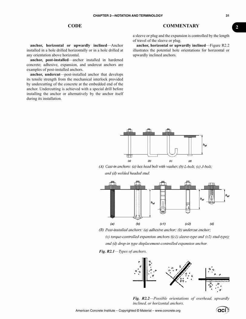
anchor, horizontal or upwardly inclined—Anchor installed in a hole drilled horizontally or in a hole drilled at any orientation above horizontal.
anchor, post-installed—anchor installed in hardened concrete; adhesive, expansion, and undercut anchors are examples of post-installed anchors.
anchor, undercut—post-installed anchor that develops its tensile strength from the mechanical interlock provided by undercutting of the concrete at the embedded end of the anchor. Undercutting is achieved with a special drill before installing the anchor or alternatively by the anchor itself during its installation.
a sleeve or plug and the expansion is controlled by the length of travel of the sleeve or plug.
anchor, horizontal or upwardly inclined—Figure R2.2 illustrates the potential hole orientations for horizontal or upwardly inclined anchors.
Fig. R2.1––Types of anchors.
Fig. R2.2––Possible orientations of overhead, upwardly inclined, or horizontal anchors.
American Concrete Institute – Copyrighted © Material – www.concrete.org
CHAPTER 2—NOTATION AND TERMINOLOGY 31
CODE COMMENTARY 2
anchor group—a number of similar anchors having approximately equal effective embedment depths with spacing s between adjacent anchors such that the projected areas overlap.
anchor pullout strength—the strength corresponding to the anchoring device or a major component of the device sliding out from the concrete without breaking out a substan-tial portion of the surrounding concrete.
anchorage device—in post-tensioned members, the hard-ware used to transfer force from prestressed reinforcement to the concrete.
anchorage device, basic monostrand—anchorage device used with any single strand or a single 15 mm or smaller diameter bar that is in accordance with 25.8.1, 25.8.2, and 25.9.3.1(a).
anchorage device, basic multistrand—anchorage device used with multiple strands, bars, or wires, or with single bars larger than 15 mm diameter that satisfies 25.8.1, 25.8.2 and 25.9.3.1(b).
anchorage device, special—anchorage device that satis-fies tests required in 25.9.3.1(c).
anchorage zone—in post-tensioned members, portion of the member through which the concentrated prestressing force is transferred to concrete and distributed more uniformly across the section; its extent is equal to the largest dimen-sion of the cross section; for anchorage devices located away from the end of a member, the anchorage zone includes the disturbed regions ahead of and behind the anchorage device.
attachment—structural assembly, external to the surface of the concrete, that transmits loads to or receives loads from the anchor.
B-region—portion of a member in which it is reasonable to assume that strains due to flexure vary linearly through section.
base of structure—level at which horizontal earthquake ground motions are assumed to be imparted to a building. This level does not necessarily coincide with the ground level.
beam—member subjected primarily to flexure and shear, with or without axial force or torsion; beams in a moment frame that forms part of the lateral-force-resisting system are predominantly horizontal members; a girder is a beam.
anchor group—For all potential failure modes (steel, concrete breakout, pullout, side-face blowout, and pryout), only those anchors susceptible to a particular failure mode should be considered when evaluating the strength associ-ated with that failure mode.
anchorage device—Most anchorage devices for post-tensioning are standard manufactured devices available from commercial sources. In some cases, non-standard details or assemblages are developed that combine various wedges and wedge plates for anchoring prestressed reinforcement. Both standard and non-standard anchorage devices may be classified as basic anchorage devices or special anchorage devices as defined in this Code and AASHTO LFRDUS.
anchorage device, basic—Devices that are so propor-tioned that they can be checked analytically for compli-ance with bearing stress and stiffness requirements without having to undergo the acceptance-testing program required of special anchorage devices.
anchorage device, special—Special anchorage devices are any devices (monostrand or multistrand) that do not meet the relevant PTI or AASHTO LFRDUS bearing stress and, where applicable, stiffness requirements. Most commer-cially marketed multi-bearing surface anchorage devices are special anchorage devices. As provided in 25.9.3, such devices can be used only if they have been shown experi-mentally to be in compliance with the AASHTO require-ments. This demonstration of compliance will ordinarily be furnished by the device manufacturer.
anchorage zone—In post-tensioned members, the portion of the member through which the concentrated prestressing force is transferred to the concrete and distributed more uniformly across the section. Its extent is equal to the largest dimension of the cross section. For anchorage devices located away from the end of a member, the anchorage zone includes the disturbed regions ahead of and behind the anchorage devices. Refer to Fig. R25.9.1.1b.
American Concrete Institute – Copyrighted © Material – www.concrete.org
32 BUILDING CODE REQUIREMENTS FOR STRUCTURAL CONCRETE (ACI 318M-14) AND COMMENTARY (ACI 318RM-14)
CODE COMMENTARY

boundary element—portion along wall and diaphragm edge, including edges of openings, strengthened by longitu-dinal and transverse reinforcement.
breakout strength, concrete—strength corresponding to a volume of concrete surrounding the anchor or group of anchors separating from the member.
building official—term used to identify the Authority having jurisdiction or individual charged with administra-tion and enforcement of provisions of the building code. Such terms as building commissioner or building inspector are variations of the title, and the term “building official” as used in this Code, is intended to include those variations, as well as others that are used in the same sense.
cementitious materials—materials that have cementing value if used in concrete either by themselves, such as portland cement, blended hydraulic cements, and expansive cement; or such materials in combination with fly ash, other raw or calcined natural pozzolans, silica fume, and slag cement.
collector—element that acts in axial tension or compres-sion to transmit forces between a diaphragm and a vertical element of the lateral-force-resisting system.
column—member, usually vertical or predominantly vertical, used primarily to support axial compressive load, but that can also resist moment, shear, or torsion. Columns used as part of a lateral-force-resisting system resist combined axial load, moment, and shear. See also moment frame.
column capital—enlargement of the top of a concrete column located directly below the slab or drop panel that is cast monolithically with the column.
compliance requirements—construction-related code requirements directed to the contractor to be incorporated into construction documents by the licensed design profes-sional, as applicable.
composite concrete flexural members—concrete flex-ural members of precast or cast-in-place concrete elements, constructed in separate placements but connected so that all elements respond to loads as a unit.
compression-controlled section—cross section in which the net tensile strain in the extreme tension reinforcement at nominal strength is less than or equal to the compression-controlled strain limit.
compression-controlled strain limit—net tensile strain at balanced strain conditions.
concrete—mixture of portland cement or any other cementitious material, fine aggregate, coarse aggregate, and water, with or without admixtures.
concrete, all-lightweight—lightweight concrete containing only lightweight coarse and fine aggregates that conform to ASTM C330M.
concrete, lightweight—concrete containing lightweight aggregate and having an equilibrium density, as determined by ASTM C567, between 1440 and 1840 kg/m3.
concrete, nonprestressed—reinforced concrete with at least the minimum amount of nonprestressed reinforcement
compliance requirements—Although primarily directed to the contractor, the compliance requirements are also commonly used by others involved with the project.
concrete, nonprestressed—Nonprestressed concrete usually contains no prestressed reinforcement. Prestressed two-way slabs require a minimum level of compressive
American Concrete Institute – Copyrighted © Material – www.concrete.org
CHAPTER 2—NOTATION AND TERMINOLOGY 33
CODE COMMENTARY 2
stress in the concrete due to effective prestress in accordance with 8.6.2.1. Two-way slabs with less than this minimum level of precompression are required to be designed as nonprestressed concrete.
concrete, normalweight—Normalweight concrete typi-cally has a density (unit weight) between 2155 and 2560 kg/m3, and is normally taken as 2320 to 2400 kg/m3.
concrete, plain—The presence of reinforcement, nonpre-stressed or prestressed, does not exclude the member from being classified as plain concrete, provided all requirements of Chapter 14 are satisfied.
concrete, prestressed—Classes of prestressed flex-ural members are defined in 24.5.2.1. Prestressed two-way slabs require a minimum level of compressive stress in the concrete due to effective prestress in accordance with 8.6.2.1. Although the behavior of prestressed members with unbonded tendons may vary from that of members with continuously bonded prestressed reinforcement, bonded and unbonded prestressed concrete are combined with nonprestressed concrete under the generic term “reinforced concrete.” Provisions common to both prestressed and nonprestressed concrete are integrated to avoid overlapping and conflicting provisions.
concrete, reinforced—Includes members satisfying the requirements for nonprestressed and prestressed concrete.
concrete, sand-lightweight—By Code terminology, sand-lightweight concrete is lightweight concrete with all of the fine aggregate replaced by sand. This definition may not be in agreement with usage by some material suppliers or contractors where the majority, but not all, of the light-weight fines are replaced by sand. For proper application of the Code provisions, the replacement limits should be stated, with interpolation if partial sand replacement is used.
and no prestressed reinforcement; or for two-way slabs, with less than the minimum amount of prestressed reinforcement.
concrete, normalweight—concrete containing only coarse and fine aggregates that conform to ASTM C33M.
concrete, plain—structural concrete with no reinforce-ment or with less than the minimum amount of reinforce-ment specified for reinforced concrete.
concrete, precast—structural concrete element cast else-where than its final position in the structure.
concrete, prestressed—reinforced concrete in which internal stresses have been introduced by prestressed rein-forcement to reduce potential tensile stresses in concrete resulting from loads, and for two-way slabs, with at least the minimum amount of prestressed reinforcement.
concrete, reinforced—structural concrete reinforced with at least the minimum amount of nonprestressed reinforcement, prestressed reinforcement, or both, as specified in this Code.
concrete, sand-lightweight—lightweight concrete containing only normalweight fine aggregate that conforms to ASTM C33M and lightweight coarse aggregate that conforms to ASTM C330M.
concrete, steel fiber-reinforced—concrete containing a prescribed amount of dispersed, randomly oriented, discon-tinuous deformed steel fibers.
concrete strength, specified compressive, (fc′)—compres-sive strength of concrete used in design and evaluated in accordance with provisions of this Code, MPa; wherever the quantity fc′ is under a radical sign, the square root of numer-ical value only is intended, and the result has units of MPa.
connection—region of a structure that joins two or more members; a connection also refers to a region that joins members of which one or more is precast.
connection, ductile—connection between one or more precast elements that experiences yielding as a result of the earthquake design displacements.
connection, strong—connection between one or more precast elements that remains elastic while adjoining members experience yielding as a result of earthquake design displacements.
construction documents—written and graphic documents and specifications prepared or assembled for describing the
American Concrete Institute – Copyrighted © Material – www.concrete.org
34 BUILDING CODE REQUIREMENTS FOR STRUCTURAL CONCRETE (ACI 318M-14) AND COMMENTARY (ACI 318RM-14)
CODE COMMENTARY
location, design, materials, and physical characteristics of the elements of a project necessary for obtaining a building permit and construction of the project.
contraction joint—formed, sawed, or tooled groove in a concrete structure to create a weakened plane and regu-late the location of cracking resulting from the dimensional change of different parts of the structure.
cover, specified concrete—distance between the outer-most surface of embedded reinforcement and the closest outer surface of the concrete.
crosstie—a continuous reinforcing bar having a seismic hook at one end and a hook not less than 90 degrees with at least a 6db extension at the other end. The hooks shall engage peripheral longitudinal bars. The 90-degree hooks of two successive crossties engaging the same longitudinal bars shall be alternated end for end.
D-region—portion of a member within a distance h of a force discontinuity or a geometric discontinuity.
design displacement—total calculated lateral displace-ment expected for the design-basis earthquake.
design information—project-specific information to be incorporated into construction documents by the licensed design professional, as applicable.
design load combination—combination of factored loads and forces.
design story drift ratio—relative difference of design displacement between the top and bottom of a story, divided by the story height.
development length—length of embedded reinforce-ment, including pretensioned strand, required to develop the design strength of reinforcement at a critical section.
discontinuity—abrupt change in geometry or loading.distance sleeve—sleeve that encases the center part of an
undercut anchor, a torque-controlled expansion anchor, or a displacement-controlled expansion anchor, but does not expand.
drop panel—projection below the slab used to reduce the amount of negative reinforcement over a column or the minimum required slab thickness, and to increase the slab shear strength.
duct—conduit, plain or corrugated, to accommodate prestressing reinforcement for post-tensioning applications.
durability—ability of a structure or member to resist dete-rioration that impairs performance or limits service life of the structure in the relevant environment considered in design.
design displacement—The design displacement is an index of the maximum lateral displacement expected in design for the design-basis earthquake. In documents such as ASCE/SEI 7 and the International Building Code, the design displacement is calculated using static or dynamic linear elastic analysis under code-specified actions consid-ering effects of cracked sections, effects of torsion, effects of vertical forces acting through lateral displacements, and modification factors to account for expected inelastic response. The design displacement generally is greater than the displacement calculated from design-level forces applied to a linear-elastic model of the building.
American Concrete Institute – Copyrighted © Material – www.concrete.org
CHAPTER 2—NOTATION AND TERMINOLOGY 35
CODE COMMENTARY 2
edge distance—distance from the edge of the concrete surface to the center of the nearest anchor.
effective depth of section—distance measured from extreme compression fiber to centroid of longitudinal tension reinforcement.
effective embedment depth—overall depth through which the anchor transfers force to or from the surrounding concrete; effective embedment depth will normally be the depth of the concrete failure surface in tension applications; for cast-in headed anchor bolts and headed studs, the effec-tive embedment depth is measured from the bearing contact surface of the head.
effective prestress—stress remaining in prestressed rein-forcement after losses in 20.3.2.6 have occurred.
embedments—items embedded in concrete, excluding reinforcement as defined in Chapter 20 and anchors as defined in Chapter 17. Reinforcement or anchors welded, bolted or otherwise connected to the embedded item to develop the strength of the assembly, are considered to be part of the embedment.
embedments, pipe—embedded pipes, conduits, and sleeves.
embedment length—length of embedded reinforcement provided beyond a critical section.
equilibrium density—density of lightweight concrete determined in accordance with ASTM C567 after exposure to a relative humidity of 50 ± 5 percent and a temperature of 23 ± 2°C for a period of time sufficient to reach constant density.
expansion sleeve—outer part of an expansion anchor that is forced outward by the center part, either by applied torque or impact, to bear against the sides of the predrilled hole. See also anchor, expansion.
extreme tension reinforcement—layer of prestressed or nonprestressed reinforcement that is the farthest from the extreme compression fiber.
finite element analysis—a numerical modeling technique in which a structure is divided into a number of discrete elements for analysis.
five percent fractile—statistical term meaning 90 percent confidence that there is 95 percent probability of the actual strength exceeding the nominal strength.
headed deformed bars—deformed bars with heads attached at one or both ends.
effective embedment depth—Effective embedment depths for a variety of anchor types are shown in Fig. R2.1.
five percent fractile—The determination of the coefficient K05 associated with the 5 percent fractile, x – K05ss depends on the number of tests, n, used to calculate the sample mean, x , and sample standard deviation, ss. Values of K05 range, for example, from 1.645 for n = ∞, to 2.010 for n = 40, and 2.568 for n = 10. With this definition of the 5 percent fractile, the nominal strength in Chapter 17 is the same as the character-istic strength in ACI 355.2 and ACI 355.4.
headed deformed bars—The bearing area of a headed deformed bar is, for the most part, perpendicular to the bar axis. In contrast, the bearing area of the head of headed stud reinforcement is a nonplanar spatial surface of revolu-tion, as shown in Fig. R20.5.1. The two types of reinforce-ment differ in other ways. The shanks of headed studs are smooth, not deformed as with headed deformed bars. The minimum net bearing area of the head of a headed deformed bar is permitted to be as small as four times the bar area.
American Concrete Institute – Copyrighted © Material – www.concrete.org
36 BUILDING CODE REQUIREMENTS FOR STRUCTURAL CONCRETE (ACI 318M-14) AND COMMENTARY (ACI 318RM-14)
CODE COMMENTARY
headed bolt—cast-in steel anchor that develops its tensile strength from the mechanical interlock provided by either a head or nut at the embedded end of the anchor.
headed stud—a steel anchor conforming to the requirements of AWS D1.1 and affixed to a plate or similar steel attachment by the stud arc welding process before casting; also referred to as a welded headed stud.
headed shear stud reinforcement—reinforcement consisting of individual headed studs or groups of studs, with anchorage provided by a head at each end, or by a head at one end and a common base rail consisting of a steel plate or shape at the other end.
hooked bolt—cast-in anchor anchored mainly by bearing of the 90-degree bend (L-bolt) or 180-degree bend (J-bolt) against the concrete, at its embedded end, and having a minimum eh equal to 3da.
hoop—closed tie or continuously wound tie, made up of one or several reinforcement elements, each having seismic hooks at both ends. A closed tie shall not be made up of interlocking headed deformed bars. See 25.7.4.
inspection—observation, verification, and required docu-mentation of the materials, installation, fabrication, erection, or placement of components and connections to determine compliance with construction documents and referenced standards.
inspection, continuous—the full-time observation, veri-fication, and required documentation of work in the area where the work is being performed.
inspection, periodic—the part-time or intermittent obser-vation, verification, and required documentation of work in the area where the work is being performed.
isolation joint—separation between adjoining parts of a concrete structure, usually a vertical plane at a designed location such as to interfere least with performance of the structure, yet such as to allow relative movement in three directions and avoid formation of cracks elsewhere in the concrete, and through which all or part of the bonded rein-forcement is interrupted.
jacking force—in prestressed concrete, temporary force exerted by a device that introduces tension into prestressing reinforcement.
joint—portion of structure common to intersecting members
licensed design professional—an individual who is licensed to practice structural design as defined by the statu-tory requirements of the professional licensing laws of the state or jurisdiction in which the project is to be constructed, and who is in responsible charge of the structural design.
load—forces or other actions that result from the weight of all building materials, occupants, and their possessions, environmental effects, differential movement, and restrained dimensional changes; permanent loads are those loads in
In contrast, the minimum stud head area is not specified in terms of the bearing area, but by the total head area which must be at least 10 times the area of the shank.
joint—The effective cross-sectional area of a joint of a special moment frame, Aj, for shear strength computations is given in 18.8.4.3.
licensed design professional—May also be referred to as “registered design professional” in other documents.
loads—A number of definitions for loads are given as the Code contains requirements that are to be met at various load levels. The terms “dead load” and “live load” refer to the unfactored, sometimes called “service” loads speci-
American Concrete Institute – Copyrighted © Material – www.concrete.org
CHAPTER 2—NOTATION AND TERMINOLOGY 37
CODE COMMENTARY 2
which variations over time are rare or of small magnitude; all other loads are variable loads.
load, dead—(a) the weights of the members, supported structure, and permanent attachments or accessories that are likely to be present on a structure in service; or (b) loads meeting specific criteria found in the general building code; without load factors.
load, factored—load, multiplied by appropriate load factors.
load, live—(a) load that is not permanently applied to a structure, but is likely to occur during the service life of the structure (excluding environmental loads); or (b) loads meeting specific criteria found in the general building code; without load factors.
load, roof live—a load on a roof produced: (a) during maintenance by workers, equipment, and materials, and (b) during the life of the structure by movable objects, such as planters or other similar small decorative appurtenances that are not occupancy related; or loads meeting specific criteria found in the general building code; without load factors.
load, service—all loads, static or transitory, imposed on a structure or element thereof, during the operation of a facility, without load factors.
load path—sequence of members and connections designed to transfer the factored loads and forces in such combinations as are stipulated in this Code, from the point of application or origination through the structure to the final support location or the foundation.
Manufacturer’s Printed Installation Instructions (MPII)—published instructions for the correct installation of an adhesive anchor under all covered installation condi-tions as supplied in the product packaging.
modulus of elasticity—ratio of normal stress to corre-sponding strain for tensile or compressive stresses below proportional limit of material.
moment frame—frame in which beams, slabs, columns, and joints resist forces predominantly through flexure, shear, and axial force; beams or slabs are predominantly horizontal or nearly horizontal; columns are predominantly vertical or nearly vertical.
moment frame, intermediate—cast-in-place beam-column frame or two-way slab-column frame without beams complying with 18.4.
moment frame, ordinary—cast-in-place or precast concrete beam-column or slab-column frame complying with 18.3.
fied or defined by the general building code. Service loads (loads without load factors) are to be used where speci-fied in the Code to proportion or investigate members for adequate serviceability. Loads used to proportion a member for adequate strength are defined as factored loads. Factored loads are service loads multiplied by the appropriate load factors for required strength except Wind and Earthquake which are already specified as strength loads in ASCE/SEI 7. The factored load terminology clarifies where the load factors are applied to a particular load, moment, or shear value as used in the Code provisions.
American Concrete Institute – Copyrighted © Material – www.concrete.org
38 BUILDING CODE REQUIREMENTS FOR STRUCTURAL CONCRETE (ACI 318M-14) AND COMMENTARY (ACI 318RM-14)
CODE COMMENTARY
one-way construction—Joists, beams, girders, and some slabs and foundations are considered one-way construction.
reinforcement, anchor—Anchor reinforcement is designed and detailed specifically for the purpose of trans-ferring anchor loads from the anchors into the member. Hair-pins are generally used for this purpose (refer to 17.4.2.9 and 17.5.2.9); however, other configurations that can be shown to effectively transfer the anchor load are acceptable.
reinforcement, deformed—Deformed reinforcement is defined as that meeting the reinforcement specifications in
moment frame, special—cast-in-place beam-column frame complying with 18.2.3 through 18.2.8; and 18.6 through 18.8. A precast beam-column frame complying with 18.2.3 through 18.2.8 and 18.9.
net tensile strain—the tensile strain at nominal strength exclusive of strains due to effective prestress, creep, shrinkage, and temperature.
nodal zone—volume of concrete around a node that is assumed to transfer strut-and-tie forces through the node.
node—point in a strut-and-tie model where the axes of the struts, ties, and concentrated forces acting on the joint intersect.
one-way construction—members designed to be capable of supporting all loads through bending in a single direction; see also two-way construction.
pedestal—member with a ratio of height-to-least lateral dimension less than or equal to 3 used primarily to support axial compressive load; for a tapered member, the least lateral dimension is the average of the top and bottom dimensions of the smaller side.
plastic hinge region—length of frame element over which flexural yielding is intended to occur due to earthquake design displacements, extending not less than a distance h from the critical section where flexural yielding initiates.
post-tensioning—method of prestressing in which prestressing reinforcement is tensioned after concrete has hardened.
precompressed tension zone—portion of a prestressed member where flexural tension, calculated using gross section properties, would occur under service loads if the prestress force was not present.
pretensioning—method of prestressing in which prestressing reinforcement is tensioned before concrete is cast.
projected area—area on the free surface of the concrete member that is used to represent the greater base of the assumed rectilinear failure surface.
projected influence area—rectilinear area on the free surface of the concrete member that is used to calculate the bond strength of adhesive anchors.
pryout strength, concrete—strength corresponding to formation of a concrete spall behind short, stiff anchors displaced in the direction opposite to the applied shear force.
reinforcement—steel element or elements embedded in concrete and conforming to 20.2 through 20.5. Prestressed reinforcement in external tendons is also considered reinforcement.
reinforcement, anchor—reinforcement used to transfer the design load from the anchors into the structural member.
reinforcement, bonded prestressed—pretensioned rein-forcement or prestressed reinforcement in a bonded tendon.
reinforcement, deformed—deformed bars, welded bar mats, deformed wire, and welded wire reinforcement
American Concrete Institute – Copyrighted © Material – www.concrete.org
CHAPTER 2—NOTATION AND TERMINOLOGY 39
CODE COMMENTARY 2
conforming to 20.2.1.3, 20.2.1.5, or 20.2.1.7, excluding plain wire.
reinforcement, nonprestressed—bonded reinforcement that is not prestressed.
reinforcement, plain—bars or wires conforming to 20.2.1.4 or 20.2.1.7 that do not conform to definition of deformed reinforcement.
reinforcement, prestressed—prestressing reinforcement that has been tensioned to impart forces to concrete.
reinforcement, prestressing—high-strength reinforce-ment such as strand, wire, or bar conforming to 20.3.1.
reinforcement, supplementary—reinforcement that acts to restrain the potential concrete breakout but is not designed to transfer the design load from the anchors into the struc-tural member.
reinforcement, welded deformed steel bar mat—mat conforming to 20.2.1.5 consisting of two layers of deformed bars at right angles to each other welded at the intersections.
reinforcement, welded wire—plain or deformed wire fabricated into sheets or rolls conforming to 20.2.1.7.
Seismic Design Category—classification assigned to a structure based on its occupancy category and the severity of the design earthquake ground motion at the site, as defined by the general building code. Also denoted by the abbrevia-tion SDC.
seismic-force-resisting system—portion of the structure designed to resist earthquake effects required by the general building code using the applicable provisions and load combinations.
seismic hook—hook on a stirrup, hoop, or crosstie having a bend not less than 135 degrees, except that circular hoops shall have a bend not less than 90 degrees; hooks shall have an extension of at least 6db, but not less than 75 mm. The hooks shall engage the longitudinal reinforcement and the extension shall project into the interior of the stirrup or hoop.
shear cap—projection below the slab used to increase the slab shear strength.
sheathing—material encasing prestressing reinforcement to prevent bonding of the prestressing reinforcement with the surrounding concrete, to provide corrosion protection, and to contain the corrosion-inhibiting coating.
side-face blowout strength, concrete—strength of anchors with deep embedment and thin side-face cover such that spalling occurs on the side face around the embedded head without breakout occurring at the top concrete surface.
spacing—center-to-center distance between adjacent items, such as longitudinal reinforcement, transverse rein-forcement, prestressing reinforcement, or anchors.
spacing, clear—least dimension between the outermost surfaces of adjacent items.
span length—distance between supports.
the Code. No other reinforcement qualifies. This definition permits accurate statement of development lengths. Bars or wire not meeting the deformation requirements or welded wire reinforcement not meeting the spacing requirements are “plain reinforcement,” for code purposes, and may be used only for spirals.
reinforcement, supplementary—Supplementary rein-forcement has a configuration and placement similar to anchor reinforcement but is not specifically designed to transfer loads from the anchors into the member. Stirrups, as used for shear reinforcement, may fall into this category.
sheathing—Typically, sheathing is a continuous, seam-less, high-density polyethylene material extruded directly on the coated prestressing reinforcement.
American Concrete Institute – Copyrighted © Material – www.concrete.org
40 BUILDING CODE REQUIREMENTS FOR STRUCTURAL CONCRETE (ACI 318M-14) AND COMMENTARY (ACI 318RM-14)
CODE COMMENTARY
special seismic systems—structural systems that use special moment frames, special structural walls, or both.
specialty insert—predesigned and prefabricated cast-in anchors specifically designed for attachment of bolted or slotted connections.
spiral reinforcement—continuously wound reinforce-ment in the form of a cylindrical helix.
splitting tensile strength (fct)—tensile strength of concrete determined in accordance with ASTM C496M as described in ASTM C330M.
steel element, brittle—element with a tensile test elonga-tion of less than 14 percent, or reduction in area of less than 30 percent at failure.
steel element, ductile—element with a tensile test elonga-tion of at least 14 percent and reduction in area of at least 30 percent; steel element meeting the requirements of ASTM A307 shall be considered ductile; except as modified by for earthquake effects, deformed reinforcing bars meeting the requirements of ASTM A615M, A706M, or A955M shall be considered as ductile steel elements.
stirrup—reinforcement used to resist shear and torsion forces in a member; typically deformed bars, deformed wires, or welded wire reinforcement either single leg or bent into L, U, or rectangular shapes and located perpendicular to, or at an angle to, longitudinal reinforcement. See also tie.
strength, design—nominal strength multiplied by a strength reduction factor ϕ.
strength, nominal—strength of a member or cross section calculated in accordance with provisions and assumptions of the strength design method of this Code before application of any strength reduction factors.
strength, required—strength of a member or cross section required to resist factored loads or related internal moments and forces in such combinations as stipulated in this Code.
stretch length—length of anchor, extending beyond concrete in which it is anchored, subject to full tensile load applied to anchor, and for which cross-sectional area is minimum and constant.
structural concrete—concrete used for structural purposes, including plain and reinforced concrete.
structural diaphragm—member, such as a floor or roof slab, that transmits forces acting in the plane of the member to vertical elements of the lateral-force-resisting system. A structural diaphragm may include chords and collectors as part of the diaphragm.
structural integrity—ability of a structure through strength, redundancy, ductility, and detailing of reinforce-
specialty insert—Specialty inserts are devices often used for handling, transportation, erection, and anchoring elements; specialty inserts are not within the scope of this Code.
steel element, brittle—The 14 percent elongation should be measured over the gauge length specified in the appro-priate ASTM standard for the steel.
steel element, ductile—The 14 percent elongation should be measured over the gauge length specified in the appropriate ASTM standard for steel. Due to concerns over fracture in cut threads, it should be verified that threaded deformed reinforcing bars satisfy the strength requirements of 25.5.7.1.
stirrup—The term “stirrup” is usually applied to trans-verse reinforcement in beams or slabs and the term “ties” or “hoops” to transverse reinforcement in compression members.
strength, nominal—Nominal or specified values of mate-rial strengths and dimensions are used in the calculation of nominal strength. The subscript n is used to denote the nominal strengths; for example, nominal axial load strength Pn, nominal moment strength Mn, and nominal shear strength Vn. For addi-tional discussion on the concepts and nomenclature for strength design, refer to the Commentary of Chapter 22.
strength, required—The subscript u is used only to denote the required strengths; for example, required axial load strength Pu, required moment strength Mu, and required shear strength Vu, calculated from the applied factored loads and forces. The basic requirement for strength design may be expressed as follows: design strength ≥ required strength; for example, ϕPn ≥ Pu; ϕMn ≥ Mu; ϕVn ≥ Vu. For additional discussion on the concepts and nomenclature for strength design, refer to the Commentary of Chapter 22.
stretch length—Length of an anchor over which inelastic elongations are designed to occur under earthquake load-ings. Examples illustrating stretch length are shown in Fig. R17.2.3.4.3.
American Concrete Institute – Copyrighted © Material – www.concrete.org
CHAPTER 2—NOTATION AND TERMINOLOGY 41
CODE COMMENTARY 2
ment to redistribute stresses and maintain overall stability if localized damage or significant overstress occurs.
structural system—interconnected members designed to meet performance requirements.
structural truss—assemblage of reinforced concrete members subjected primarily to axial forces.
structural wall—wall proportioned to resist combina-tions of shears, moments, and axial forces in the plane of the wall; a shear wall is a structural wall.
structural wall, ordinary reinforced concrete—a wall complying with Chapter 11.
structural wall, ordinary plain concrete—a wall complying with Chapter 14.
structural wall, intermediate precast—a wall complying with 18.5.
structural wall, special—a cast-in-place structural wall in accordance with 18.2.3 through 18.2.8 and 18.10; or a precast structural wall in accordance with 18.2.3 through 18.2.8 and 18.11.
strut—compression member in a strut-and-tie model representing the resultant of a parallel or a fan-shaped compression field.
strut, bottle-shaped—strut that is wider at mid-length than at its ends.
strut-and-tie model—truss model of a member or of a D-region in such a member, made up of struts and ties connected at nodes and capable of transferring the factored loads to the supports or to adjacent B-regions.
tendon—in post-tensioned members, a tendon is a complete assembly consisting of anchorages, prestressing reinforcement, and sheathing with coating for unbonded applications or ducts filled with grout for bonded applications.
tendon, bonded—tendon in which prestressed reinforce-ment is continuously bonded to the concrete through grouting of ducts embedded within the concrete cross section.
tendon, external—a tendon external to the member concrete cross section in post-tensioned applications.
tendon, unbonded—tendon in which prestressed rein-forcement is prevented from bonding to the concrete. The prestressing force is permanently transferred to the concrete at the tendon ends by the anchorages only.
tension-controlled section—a cross section in which the net tensile strain in the extreme tension steel at nominal strength is greater than or equal to 0.005.
tie—(a) loop of reinforcing bar or wire enclosing longi-tudinal reinforcement; a continuously wound transverse bar or wire in the form of a circle, rectangle, or other polygonal
structural wall, intermediate precast—Requirements of 18.5 are intended to result in an intermediate precast struc-tural wall having minimum strength and toughness equiv-alent to that for an ordinary reinforced concrete structural wall of cast-in-place concrete. A precast concrete wall not satisfying the requirements of 18.5 is considered to have ductility and structural integrity less than that for an inter-mediate precast structural wall.
structural wall, special—Requirements of 18.2.3 through 18.2.8 and 18.11 are intended to result in a special precast structural wall having minimum strength and toughness equivalent to that for a special reinforced concrete structural wall of cast-in-place concrete.
tendon, external—In new or existing post-tensioned applications, a tendon totally or partially external to the member concrete cross section, or inside a box section, and attached at the anchor device and deviation points.
American Concrete Institute – Copyrighted © Material – www.concrete.org
42 BUILDING CODE REQUIREMENTS FOR STRUCTURAL CONCRETE (ACI 318M-14) AND COMMENTARY (ACI 318RM-14)
CODE COMMENTARY
shape without reentrant corners enclosing longitudinal rein-forcement; see also stirrup, hoop; (b) tension element in a strut-and-tie model.
transfer—act of transferring stress in prestressing rein-forcement from jacks or pretensioning bed to concrete member.
transfer length—length of embedded pretensioned rein-forcement required to transfer the effective prestress to the concrete.
two-way construction—members designed to be capable of supporting loads through bending in two directions; some slabs and foundations are considered two-way construction. See also one-way construction.
wall—a vertical element designed to resist axial load, lateral load, or both, with a horizontal length-to-thickness ratio greater than 3, used to enclose or separate spaces.
wall segment—portion of wall bounded by vertical or horizontal openings or edges.
wall segment, horizontal—segment of a structural wall, bounded vertically by two openings or by an opening and an edge.
wall segment, vertical—segment of a structural wall, bounded horizontally by two openings or by an opening and an edge; wall piers are vertical wall segments.
wall pier—a vertical wall segment within a structural wall, bounded horizontally by two openings or by an opening and an edge, with ratio of horizontal length to wall thickness (ℓw/bw) less than or equal to 6.0, and ratio of clear height to horizontal length (hw/ℓw) greater than or equal to 2.0.
water-cementitious materials ratio—ratio of mass of water, excluding that absorbed by the aggregate, to the mass of cementitious materials in a mixture, stated as a decimal.
work—the entire construction or separately identifiable parts thereof that are required to be furnished under the construction documents.
yield strength—specified minimum yield strength or yield point of reinforcement; yield strength or yield point shall be determined in tension according to applicable ASTM standards as modified by this Code.
wall segment, horizontal—A horizontal wall segment is shown in Fig. R18.10.4.5.
wall pier—Wall piers are vertical wall segments with dimensions and reinforcement intended to result in shear demand being limited by flexural yielding of the vertical reinforcement in the pier..
American Concrete Institute – Copyrighted © Material – www.concrete.org
CHAPTER 2—NOTATION AND TERMINOLOGY 43
CODE COMMENTARY 2

American Concrete Institute – Copyrighted © Material – www.concrete.org
44 BUILDING CODE REQUIREMENTS FOR STRUCTURAL CONCRETE (ACI 318M-14) AND COMMENTARY (ACI 318RM-14)
Notes
American Concrete Institute – Copyrighted © Material – www.concrete.org
CHAPTER 3—REFERENCED STANDARDS 45
CODE COMMENTARY
3CHAPTER 3—REFERENCED STANDARDS
3.1—Scope 3.1.1 Standards, or specific sections thereof, cited in this
Code, including Annex, Appendixes, or Supplements where prescribed, are referenced without exception in this Code, unless specifically noted. Cited standards are listed in the following with their serial designations, including year of adoption or revision.
3.2—Referenced standards 3.2.1 American Association of State Highway and Trans-
portation Officials (AASHTO)LRFDUS-6—LRFD Bridge Design Specifications, 6th
Edition, 2012, Articles 5.10.9.6, 5.10.9.7.2, and 5.10.9.7.3LRFDCONS-3—LRFD Bridge Construction Specifica-
tions, 3rd Edition, 2010, Article 10.3.2.3
3.2.2 American Concrete Institute (ACI) 301-10—Specifications for Structural Concrete, Article 4.2.3318.2-14—Building Code Requirements for Concrete
Thin Shells and Commentary332-14—Residential Code Requirements for Structural
Concrete and Commentary355.2-07—Qualification of Post-Installed Mechanical
Anchors in Concrete and Commentary355.4-11—Qualification of Post-Installed Adhesive
Anchors in Concrete374.1-05—Acceptance Criteria for Moment Frames
Based on Structural Testing423.7-14—Specification for Unbonded Single-Strand
Tendon Materials550.3-13—Design Specification for Unbonded Post-
Tensioned Precast Concrete Special Moment Frames Satis-fying ACI 374.1 and Commentary
ITG-5.1-07—Acceptance Criteria for Special Unbonded Post-Tensioned Precast Structural Walls Based on Validation Testing
ITG-5.2-09—Requirements for Design of a Special Unbonded Post-Tensioned Precast Wall Sastifying ACI ITG-5.1 and Commentary
3.2.3 American Society of Civil Engineers (ASCE) ASCE/SEI 7-10—Minimum Design Loads for Build-
ings and Other Structures, Sections 2.3.3, Load Combina-tions Including Flood Loads; and 2.3.4, Load Combinations Including Atmospheric Ice Loads
3.2.4 ASTM International A36/A36M-12—Standard Specification for Carbon Struc-
tural Steel
R3—REFERENCED STANDARDS
R3.1—Scope R3.1.1 In this Code, references to standard specifications
or other material are to a specific edition of the cited docu-ment. This is done by using the complete serial designation for the referenced standard including the title that indicates the subject and year of adoption. All standards referenced in this Code are listed in this chapter, with the title and complete serial designation. In other sections of the Code, referenced standards are abbreviated to include only the serial desig-nation without a title or date. These abbreviated references correspond to specific standards listed in this chapter.
R3.2—Referenced standards R3.2.1 Three articles of the AASHTO LRFD Specifica-
tions for Highway Bridge Design (AASHTO LRFDUS) and one article of the AASHTO LRFD Construction Specifica-tions (AASHTO LRFDCONS) are cited in Chapters 2 and 25 of this Code.
R3.2.2 Article 4.2.3 of ACI 301 is referenced for the method of mixture proportioning cited in 26.4.3.1(b).
Prior to 2014, the provisions of ACI 318.2 were specified in Chapter 19 of the ACI 318 Building Code.
ACI 355.2 contains qualification requirements for testing and evaluating post-installed expansion and undercut anchors for use in both cracked and uncracked concrete.
ACI 355.4 contains qualification requirements for testing and evaluating adhesive anchors for use in both cracked and uncracked concrete.
ACI 423.7 requires the use of encapsulated tendon systems for applications subject to this Code.
R3.2.3 The two specific sections of ASCE 7 are referenced for the purposes cited in 5.3.9 and 5.3.10.
R3.2.4 The ASTM standards listed are the latest editions at the time these code provisions were adopted. ASTM stan-dards are revised frequently relative to the revision cycle for
American Concrete Institute – Copyrighted © Material – www.concrete.org
46 BUILDING CODE REQUIREMENTS FOR STRUCTURAL CONCRETE (ACI 318M-14) AND COMMENTARY (ACI 318RM-14)
CODE COMMENTARY
A53/A53M-12—Standard Specification for Pipe, Steel, Black and Hot-Dipped, Zinc-Coated, Welded and Seamless
A184/A184M-06(2011)—Standard Specification for Welded Deformed Steel Bar Mats for Concrete Reinforcement
A242/A242M-13—Standard Specification for High-Strength Low-Alloy Structural Steel
A307-12—Standard Specification for Carbon Steel Bolts, Studs, and Threaded Rod 60000 PSI Tensile Strength
A370-14—Standard Test Methods and Definitions for Mechanical Testing of Steel Products
A416/A416M-12a—Standard Specification for Steel Strand, Uncoated Seven-Wire for Prestressed Concrete
A421/A421M-10—Standard Specification for Uncoated Stress-Relieved Steel Wire for Prestressed Concrete, including Supplementary Requirement SI, Low-Relaxation Wire and Relaxation Testing
A500/A500M-13—Standard Specification for Cold-Formed Welded and Seamless Carbon Steel Structural Tubing in Rounds and Shapes
A501-07—Standard Specification for Hot-Formed Welded and Seamless Carbon Steel Structural Tubing
A572/A572M-13a—Standard Specification for High-Strength Low-Alloy Columbium-Vanadium Structural Steel
A588/A588M-10—Standard Specification for High-Strength Low-Alloy Structural Steel, up to 50 ksi [345 MPa] Minimum Yield Point, with Atmospheric Corrosion Resistance
A615/A615M-14—Standard Specification for Deformed and Plain Carbon-Steel Bars for Concrete Reinforcement
A706/A706M-14—Standard Specification for Deformed and Plain Low-Alloy Steel Bars for Concrete Reinforcement
A722/A722M-12—Standard Specification for Uncoated High-Strength Steel Bars for Prestressing Concrete
A767/A767M-09—Standard Specification for Zinc-Coated (Galvanized) Steel Bars for Concrete Reinforcement
A775/A775M-07b(2014)—Standard Specification for Epoxy-Coated Steel Reinforcing Bars
A820/A820M-11—Standard Specification for Steel Fibers for Fiber-Reinforced Concrete
A884/A884M-14—Standard Specification for Epoxy-Coated Steel Wire and Welded Wire Reinforcement
A934/A934M-13—Standard Specification for Epoxy-Coated Prefabricated Steel Reinforcing Bars
A955/A955M-14—Standard Specification for Deformed and Plain Stainless-Steel Bars for Concrete Reinforcement
A970/A970M-13a—Standard Specification for Headed Steel Bars for Concrete Reinforcement, including Annex A1 Requirements for Class HA Head Dimensions
A992/A992M-11—Standard Specification for Structural Steel Shapes
A996/A996M-14—Standard Specification for Rail-Steel and Axle-Steel Deformed Bars for Concrete Reinforcement
A1022/A1022M-14—Standard Specification for Deformed and Plain Stainless Steel Wire and Welded Wire for Concrete Reinforcement
the Code. Current and historical editions of the referenced standards can be obtained from ASTM International. Use of an edition of a standard other than that referenced in the Code obligates the user to evaluate if any differences in the nonconforming edition are significant to use of the standard.
Many of the ASTM standards are combined standards as denoted by the dual designation, such as ASTM A36/A36M. For simplicity, these combined standards are refer-enced without the metric (M) designation within the text of the Code and Commentary. In this provision, however, the complete designation is given because that is the official designation for the standard.
American Concrete Institute – Copyrighted © Material – www.concrete.org
CHAPTER 3—REFERENCED STANDARDS 47
CODE COMMENTARY
3A1035/A1035M-14—Standard Specification for Deformed and Plain, Low-Carbon, Chromium, Steel Bars for Concrete Reinforcement
A1044/A1044M-05(2010)—Standard Specification for Steel Stud Assemblies for Shear Reinforcement of Concrete
A1055/A1055M-10ε1—Standard Specification for Zinc and Epoxy Dual-Coated Steel Reinforcing Bars
A1060/A1060M-14—Standard Specification for Zinc-Coated (Galvanized) Steel Welded Wire Reinforcement, Plain and Deformed, for Concrete
A1064/A1064M-13—Standard Specification for Carbon-Steel Wire and Welded Wire Reinforcement, Plain and Deformed, for Concrete
A1085-13—Standard Specification for Cold-Formed Welded Carbon Steel Hollow Structural Sections (HSS)
C29/C29M-09—Standard Test Method for Bulk Density (“Unit Weight”) and Voids in Aggregate
C31/C31M-12—Standard Practice for Making and Curing Concrete Test Specimens in the Field
C33/C33M-13—Standard Specification for Concrete Aggregates
C39/C39M-14a—Standard Test Method for Compressive Strength of Cylindrical Concrete Specimens
C42/C42M-13—Standard Test Method for Obtaining and Testing Drilled Cores and Sawed Beams of Concrete
C94/C94M-14—Standard Specification for Ready-Mixed Concrete
C144-11—Standard Specification for Aggregate for Masonry Mortar
C150/C150M-12—Standard Specification for Portland Cement
C172/C172M-14—Standard Practice for Sampling Freshly Mixed Concrete
C173/C173M-14—Standard Test Method for Air Content of Freshly Mixed Concrete by the Volumetric Method
C231/C231M-14—Standard Test Method for Air Content of Freshly Mixed Concrete by the Pressure Method
C260/C260M-10a—Standard Specification for Air-Entraining Admixtures for Concrete
C330/C330M-14—Standard Specification for Light-weight Aggregates for Structural Concrete
C494/C494M-13—Standard Specification for Chemical Admixtures for Concrete
C496/C496M-11—Standard Test Method for Splitting Tensile Strength of Cylindrical Concrete Specimens
C567/C567M-14—Standard Test Method for Determining Density of Structural Lightweight Concrete
C595/C595M-14—Standard Specification for Blended Hydraulic Cements
C618-12a—Standard Specification for Coal Fly Ash and Raw or Calcined Natural Pozzolan for Use in Concrete
C685/C685M-11—Standard Specification for Concrete Made by Volumetric Batching and Continuous Mixing
C845/C845M-12—Standard Specification for Expansive Hydraulic Cement

American Concrete Institute – Copyrighted © Material – www.concrete.org
48 BUILDING CODE REQUIREMENTS FOR STRUCTURAL CONCRETE (ACI 318M-14) AND COMMENTARY (ACI 318RM-14)
CODE COMMENTARY
C989/C989M-13—Standard Specification for Slag Cement for Use in Concrete and Mortars
C1012/C1012M-13—Standard Test Method for Length Change of Hydraulic-Cement Mortars Exposed to a Sulfate Solution
C1017/C1017M-13—Standard Specification for Chem-ical Admixtures for Use in Producing Flowing Concrete
C1077-14—Standard Practice for Laboratories Testing Concrete and Concrete Aggregates for Use in Construction and Criteria for Testing Agency Evaluation
C1116/C1116M-10a—Standard Specification for Fiber-Reinforced Concrete
C1157/C1157M-11—Standard Performance Specification for Hydraulic Cement
C1218/C1218M-99(2008)—Standard Test Method for Water-Soluble Chloride in Mortar and Concrete
C1240-14—Standard Specification for Silica Fume Used in Cementitious Mixtures
C1580-09ε1—Standard Test for Water-Soluble Sulfate in Soil
C1582/C1582M-11—Standard Specification for Admix-tures to Inhibit Chloride-Induced Corrosion of Reinforcing Steel in Concrete
C1602/C1602M-12—Standard Specification for Mixing Water Used in the Production of Hydraulic Cement Concrete
C1609/C1609M-12—Standard Test Method for Flexural Performance of Fiber-Reinforced Concrete (Using Beam with Third-Point Loading)
D516-11—Standard Test Method for Sulfate Ion in WaterD4130-08—Standard Test Method for Sulfate Ion in
Brackish Water, Seawater, and Brines
3.2.5 American Welding Society (AWS)D1.1/D1.1M: 2010—Structural Welding Code – SteelD1.4/D1.4M: 2011—Structural Welding Code – Rein-
forcing Steel
CHAPTER 4—STRUCTURAL SYSTEM REQUIREMENTS
4.1—Scope 4.1.1 This chapter shall apply to design of structural
concrete in structures or portions of structures defined in Chapter 1.
4.2—Materials 4.2.1 Design properties of concrete shall be selected to be
in accordance with Chapter 19.
4.2.2 Design properties of reinforcement shall be selected to be in accordance with Chapter 20.
4.3—Design loads 4.3.1 Loads and load combinations considered in design
shall be in accordance with Chapter 5.
4.4—Structural system and load paths 4.4.1 The structural system shall include (a) through (g),
as applicable:
(a) Floor construction and roof construction, including one-way and two-way slabs(b) Beams and joists(c) Columns(d) Walls(e) Diaphragms(f) Foundations(g) Joints, connections, and anchors as required to transmit forces from one component to another
4.4.2 Design of structural members including joints and connections given in 4.4.1 shall be in accordance with Chap-ters 7 through 18.
R4—STRUCTURAL SYSTEM REQUIREMENTS
R4.1—Scope This chapter was added to the 2014 Code to introduce
structural system requirements. Requirements more strin-gent than the Code provisions may be desirable for unusual construction or construction where enhanced performance is appropriate. The Code and Commentary must be supple-mented with sound engineering knowledge, experience, and judgment.
R4.2—Materials Chapter 3 identifies the referenced standards permitted for
design. Chapters 19 and 20 establish properties of concrete and steel reinforcement permitted for design. Chapter 26 presents construction requirements for concrete materials, proportioning, and acceptance of concrete.
R4.3—Design loads R4.3.1 The provisions in Chapter 5 are based on ASCE/
SEI 7. The design loads include, but are not limited to, dead loads, live loads, snow loads, wind loads, earth-quake effects, prestressing effects, crane loads, vibration, impact, shrinkage, temperature changes, creep, expansion of shrinkage-compensating concrete, and predicted unequal settlement of supports. Other project-specific loads may be specified by the licensed design professional.
R4.4—Structural system and load paths R4.4.1 Structural concrete design has evolved from
emphasizing the design of individual members to designing the structure as an entire system. A structural system consists of structural members, joints, and connections, each performing a specific role or function. A structural member may belong to one or more structural systems, serving different roles in each system and having to meet all the detailing requirements of the structural systems of which they are a part. Joints and connections are locations common to intersecting members or are items used to connect one member to another, but the distinction between members, joints, and connections can depend on how the structure is idealized. Throughout this chapter, the term “members” often refers to “structural members, joints, and connections.”
Although the Code is written considering that a structural system comprises these members, many alternative arrange-ments are possible because not all structural member types are used in all building structural systems. The selection types of the members to use in a specific project and the role or roles these member types play is made by the licensed design professional complying with requirements of the Code.
R4.4.2 In the chapter for each type of structural member, requirements follow the same general sequence and scope, including general requirements, design limits, required strength, design strength, reinforcement limits, reinforce-
American Concrete Institute – Copyrighted © Material – www.concrete.org
CHAPTER 4—STRUCTURAL SYSTEM REQUIREMENTS 49
CODE COMMENTARY
4
4.4.3 It shall be permitted to design a structural system comprising structural members not in accordance with 4.4.1 and 4.4.2, provided the structural system is approved in accordance with 1.10.1.
4.4.4 The structural system shall be designed to resist the factored loads in load combinations given in 4.3 without exceeding the appropriate member design strengths, consid-ering one or more continuous load paths from the point of load application or origination to the final point of resistance.
4.4.5 Structural systems shall be designed to accommo-date anticipated volume change and differential settlement.
4.4.6 Seismic-force-resisting system
4.4.6.1 Every structure shall be assigned to a Seismic Design Category in accordance with the general building code or as determined by the authority having jurisdiction in areas without a legally adopted building code.
4.4.6.2 Structural systems designated as part of the seismic-force-resisting system shall be restricted to those systems designated by the general building code or as deter-mined by the authority having jurisdiction in areas without a legally adopted building code.
4.4.6.3 Structural systems assigned to Seismic Design Category A shall satisfy the applicable requirements of this Code. Structures assigned to Seismic Design Category A are not required to be designed in accordance with Chapter 18.
ment detailing, and other requirements unique to the type of member.
R4.4.3 Some materials, structural members, or systems that may not be recognized in the prescriptive provisions of the Code may still be acceptable if they meet the intent of the Code. Section 1.10.1 outlines the procedures for obtaining approval of alternative materials and systems.
R4.4.4 The design should be based on members and connections that provide design strengths not less than the strengths required to transfer the loads along the load path. The licensed design professional may need to study one or more alternative paths to identify weak links along the sequence of elements that constitute each load path.
R4.4.5 The effects of column and wall creep and shrinkage, restraint of creep and shrinkage in long roof and floor systems, creep caused by prestress forces, volume changes caused by temperature variation, as well as potential damage to supporting members caused by these volume changes should be considered in design. Reinforcement, closure strips, or expansion joints are common ways of accommodating these effects. Minimum shrinkage and temperature reinforcement controls cracking to an acceptable level in many concrete structures of ordinary proportions and exposures.
Differential settlement or heave may be an important consideration in design. Geotechnical recommendations to allow for nominal values of differential settlement and heave are not normally included in design load combinations for ordinary building structures.
R4.4.6 Seismic-force-resisting system
R4.4.6.1 Design requirements in the Code are based on the seismic design category to which the structure is assigned. In general, the seismic design category relates to seismic risk level, soil type, occupancy, and building use. Assignment of a building to a seismic design category is under the jurisdic-tion of a general building code rather than this Code. In the absence of a general building code, ASCE/SEI 7 provides the assignment of a building to a seismic design category.
R4.4.6.2 The general building code prescribes, through ASCE/SEI 7, the types of structural systems permitted as part of the seismic-force-resisting system based on consider-ations such as seismic design category and building height. The seismic design requirements for systems assigned to Seismic Design Categories B through F are prescribed in Chapter 18. Other systems can be used if approved by the building official.
R4.4.6.3 Structures assigned to Seismic Design Category A are subject to the lowest seismic hazard. Chapter 18 does not apply.
American Concrete Institute – Copyrighted © Material – www.concrete.org
50 BUILDING CODE REQUIREMENTS FOR STRUCTURAL CONCRETE (ACI 318M-14) AND COMMENTARY (ACI 318RM-14)
CODE COMMENTARY
4.4.6.4 Structural systems assigned to Seismic Design Category B, C, D, E, or F shall satisfy the requirements of Chapter 18 in addition to applicable requirements of other chapters of this Code.
4.4.6.5 Structural members assumed not to be part of the seismic-force-resisting system shall be permitted, subject to the requirements of 4.4.6.5.1 and 4.4.6.5.2.
4.4.6.5.1 In structures assigned to Seismic Design Cate-gory B, C, D, E, or F, the effects of those structural members on the response of the system shall be considered and accom-modated in the structural design.
4.4.6.5.2 In structures assigned to Seismic Design Cate-gory B, C, D, E, or F, the consequences of damage to those structural members shall be considered.
4.4.6.5.3 In structures assigned to Seismic Design Cate-gory D, E, or F, structural members not considered part of the seismic-force-resisting system shall meet the applicable requirements in Chapter 18.
4.4.6.6 Effects of nonstructural members shall be accounted for as described in 18.2.2.1 and consequences of damage to nonstructural members shall be considered.
4.4.7 Diaphragms
4.4.7.1 Diaphragms, such as floor or roof slabs, shall be designed to resist simultaneously both out-of-plane gravity loads and in-plane lateral forces in load combinations given in 4.3.
4.4.7.2 Diaphragms and their connections to framing members shall be designed to transfer forces between the diaphragm and framing members.
4.4.7.3 Diaphragms and their connections shall be designed to provide lateral support to vertical, horizontal, and inclined elements.
4.4.7.4 Diaphragms shall be designed to resist applicable lateral loads from soil and hydrostatic pressure and other loads assigned to the diaphragm by structural analysis.
R4.4.6.4 Chapter 18 contains provisions that are appli-cable depending on the seismic design category and on the seismic-force-resisting system used. Not all structural member types have specific requirements in all seismic design categories. For example, Chapter 18 does not include requirements for structural walls in Seismic Design Catego-ries B and C, but does include special provisions for Seismic Design Categories D, E, and F.
R4.4.6.5 In Seismic Design Categories D, E, and F, struc-tural members not considered part of the seismic-force-resisting system are required to be designed to accommodate drifts and forces that occur as the building responds to an earthquake.
R4.4.6.6 Although the design of nonstructural elements for earthquake effects is not included in the scope of this Code, the potential negative effects of nonstructural elements on the structural behavior need to be considered in Seismic Design Categories B, C, D, E, and F. Interaction of nonstructural elements with the structural system—for example, the short-column effect—had led to failure of structural members and collapse of some structures during earthquakes in the past.
R4.4.7 Diaphragms—Floor and roof slabs play a dual role by simultaneously supporting gravity loads and transmitting lateral forces in their own plane as a diaphragm. General requirements for diaphragms are provided in Chapter 12, and roles of the diaphragm described in the Commentary to that chapter. Additional requirements for design of diaphragms in structures assigned to Seismic Design Categories D, E, and F are prescribed in Chapter 18.
American Concrete Institute – Copyrighted © Material – www.concrete.org
CHAPTER 4—STRUCTURAL SYSTEM REQUIREMENTS 51
CODE COMMENTARY
4
4.4.7.5 Collectors shall be provided where required to transmit forces between diaphragms and vertical elements.
4.4.7.6 Diaphragms that are part of the seismic-force-resisting system shall be designed for the applied forces. In structures assigned to Seismic Design Category D, E, and F, the diaphragm design shall be in accordance with Chapter 18.
4.5—Structural analysis 4.5.1 Analytical procedures shall satisfy compatibility of
deformations and equilibrium of forces.
4.5.2 The methods of analysis given in Chapter 6 shall be permitted.
4.6—Strength 4.6.1 Design strength of a member and its joints and
connections, in terms of moment, axial force, shear, torsion, and bearing, shall be taken as the nominal strength Sn multi-plied by the applicable strength reduction factor ϕ.
4.6.2 Structures and structural members shall have design strength at all sections, ϕSn, greater than or equal to the required strength U calculated for the factored loads and forces in such combinations as required by this Code or the general building code.
R4.4.7.5 All structural systems must have a complete load path in accordance with 4.4.4. The load path includes collec-tors where required.
R4.5—Structural analysis The role of analysis is to estimate the internal forces
and deformations of the structural system and to establish compliance with the strength, serviceability, and stability requirements of the Code. The use of computers in struc-tural engineering has made it feasible to perform analysis of complex structures. The Code requires that the analytical procedure used meets the fundamental principles of equilib-rium and compatibility of deformations, permitting a number of analytical techniques, including the strut-and-tie method required for discontinuity regions, as provided in Chapter 6.
R4.6—Strength The basic requirement for strength design may be
expressed as follows:
design strength ≥ required strength
ϕSn ≥ U
In the strength design procedure, the level of safety is provided by a combination of factors applied to the loads and strength reduction factors ϕ applied to the nominal strengths.
The strength of a member or cross section, calculated using standard assumptions and strength equations, along with nominal values of material strengths and dimensions, is referred to as nominal strength and is generally designated Sn. Design strength or usable strength of a member or cross section is the nominal strength reduced by the applicable strength reduction factor ϕ. The purpose of the strength reduction factor is to account for the probability of under-strength due to variations of in-place material strengths and dimensions, the effect of simplifying assumptions in the design equations, the degree of ductility, potential failure mode of the member, the required reliability, and signifi-cance of failure and existence of alternative load paths for the member in the structure.
This Code, or the general building code, prescribes design load combinations, also known as factored load combina-tions, which define the way different types of loads are multiplied (factored) by individual load factors and then combined to obtain a factored load U. The individual load factors and additive combination reflect the variability in magnitude of the individual load effect, the probability of simultaneous occurrence of various load effects, and the assumptions and approximations made in the structural anal-ysis when determining required design strengths.
American Concrete Institute – Copyrighted © Material – www.concrete.org
52 BUILDING CODE REQUIREMENTS FOR STRUCTURAL CONCRETE (ACI 318M-14) AND COMMENTARY (ACI 318RM-14)
CODE COMMENTARY

4.7—Serviceability 4.7.1 Evaluation of performance at service load condi-
tions shall consider reactions, moments, torsions, shears, and axial forces induced by prestressing, creep, shrinkage, temperature change, axial deformation, restraint of attached structural members, and foundation settlement.
4.7.2 For structures, structural members, and their connec-tions, the requirements of 4.7.1 shall be deemed to be satis-fied if designed in accordance with the provisions of the applicable member chapters.
4.8—Durability 4.8.1 Concrete mixtures shall be designed in accordance
with the requirements of 19.3.2 and 26.4, considering appli-cable environmental exposure to provide required durability.
4.8.2 Reinforcement shall be protected from corrosion in accordance with 20.6.
4.9—Sustainability 4.9.1 The licensed design professional shall be permitted
to specify in the construction documents sustainability requirements in addition to strength, serviceability, and durability requirements of this Code.
4.9.2 The strength, serviceability, and durability require-ments of this Code shall take precedence over sustainability considerations.
A typical design approach, when linear analysis is appli-cable, is to analyze the structure for individual unfactored load cases, and then combine the individual unfactored load cases in a factored load combination to determine the design load effects. Where effects of loads are nonlinear—for example, in foundation uplift—the factored loads are applied simulta-neously to determine the nonlinear, factored load effect. The load effect includes moments, shears, axial forces, torsions, and bearing forces. Required strength or strengths are the maximum absolute values of negative and positive factored load effects as applicable. Sometimes, design displacements are determined for factored load effects.
In the course of applying these principles, the licensed design professional should be aware that providing more strength than required does not necessarily lead to a safer structure because doing so may change the potential failure mode. For example, increasing longitudinal reinforcement area beyond that required for moment strength as derived from analysis without increasing transverse reinforcement could increase the probability of a shear failure occurring prior to a flexural failure.
R4.7—Serviceability Serviceability refers to the ability of the structural system
or structural member to provide appropriate behavior and functionality under the actions affecting the system. Service-ability requirements address issues such as deflections and cracking, among others.
Except as stated in Chapter 24, service-level load combi-nations are not defined in this Code, but are discussed in Appendix C of ASCE/SEI 7-10. Appendixes to ASCE/SEI 7 are not considered mandatory parts of the standard.
R4.8—Durability The environment where the structure will be located will
dictate the exposure category for materials selection, design details, and construction requirements to minimize potential for premature deterioration of the structure caused by envi-ronmental effects. Durability of a structure is also impacted by the level of preventative maintenance, which is not addressed in the Code.
Chapter 19 provides requirements for protecting concrete against major environmental causes of deterioration.
R4.9—Sustainability The Code provisions for strength, serviceability, and
durability are minimum requirements to achieve a safe and durable concrete structure. The Code permits the owner or the licensed design professional to specify require-ments higher than the minimums mandated in the Code. Such optional requirements can include higher strengths, more restrictive deflection limits, enhanced durability, and sustainability provisions.
American Concrete Institute – Copyrighted © Material – www.concrete.org
CHAPTER 4—STRUCTURAL SYSTEM REQUIREMENTS 53
CODE COMMENTARY
4
4.10—Structural integrity 4.10.1 General
4.10.1.1 Reinforcement and connections shall be detailed to tie the structure together effectively and to improve overall structural integrity.
4.10.2 Minimum requirements for structural integrity
4.10.2.1 Structural members and their connections shall be in accordance with structural integrity requirements in Table 4.10.2.1.
Table 4.10.2.1—Minimum requirements for structural integrity
Member type SectionNonprestressed two-way slabs 8.7.4.2
Prestressed two-way slabs 8.7.5.6Nonprestressed two-way joist systems 8.8.1.6
Cast-in-place beam 9.7.7Nonprestressed one-way joist system 9.8.1.6
Precast joints and connections 16.2.1.8
4.11—Fire resistance 4.11.1 Structural concrete members shall satisfy the fire
protection requirements of the general building code.
4.11.2 Where the general building code requires a thick-ness of concrete cover for fire protection greater than the concrete cover specified in 20.6.1, such greater thickness shall govern.
4.12—Requirements for specific types of construction
4.12.1 Precast concrete systems
4.12.1.1 Design of precast concrete members and connec-tions shall include loading and restraint conditions from initial fabrication to end use in the structure, including form removal, storage, transportation, and erection.
4.12.1.2 Design, fabrication, and construction of precast members and their connections shall include the effects of tolerances.
R4.10—Structural integrity R4.10.1 General
R4.10.1.1 It is the intent of the structural integrity require-ments to improve redundancy and ductility through detailing of reinforcement and connections so that, in the event of damage to a major supporting element or an abnormal loading, the resulting damage will be localized and the struc-ture will have a higher probability of maintaining overall stability.
Integrity requirements for selected structural member types are included in the corresponding member chapter in the sections noted.
R4.10.2 Minimum requirements for structural integrity—Structural members and their connections referred to in this section include only member types that have specific require-ments for structural integrity. Notwithstanding, detailing requirements for other member types address structural integrity indirectly. Such is the case for detailing of one-way slabs as provided in 7.7.
R4.11—Fire resistance Additional guidance on fire resistance of structural
concrete is provided by ACI 216.1.
R4.12—Requirements for specific types of construction
This section contains requirements that are related to specific types of construction. Additional requirements that are specific to member types appear in the corresponding member chapters.
R4.12.1 Precast concrete systems—All requirements in the Code apply to precast systems and members unless specifically excluded. In addition, some requirements apply specifically to precast concrete. This section contains specific requirements for precast systems. Other sections of this Code also provide specific requirements, such as required concrete cover, for precast systems.
Precast systems differ from monolithic systems in that the type of restraint at supports, the location of supports, and the induced stresses in the body of the member vary during
American Concrete Institute – Copyrighted © Material – www.concrete.org
54 BUILDING CODE REQUIREMENTS FOR STRUCTURAL CONCRETE (ACI 318M-14) AND COMMENTARY (ACI 318RM-14)
CODE COMMENTARY
4.12.1.3 When precast members are incorporated into a structural system, the forces and deformations occurring in and adjacent to connections shall be included in the design.
4.12.1.4 Where system behavior requires in-plane loads to be transferred between the members of a precast floor or wall system, (a) and (b) shall be satisfied:
(a) In-plane load paths shall be continuous through both connections and members.(b) Where tension loads occur, a load path of steel or steel reinforcement, with or without splices, shall be provided.
4.12.1.5 Distribution of forces that act perpendicular to the plane of precast members shall be established by anal-ysis or test.
4.12.2 Prestressed concrete systems
4.12.2.1 Design of prestressed members and systems shall be based on strength and on behavior at service conditions at all critical stages during the life of the structure from the time prestress is first applied.
4.12.2.2 Provisions shall be made for effects on adjoining construction of elastic and plastic deformations, deflec-tions, changes in length, and rotations due to prestressing. Effects of temperature change, restraint of attached struc-tural members, foundation settlement, creep, and shrinkage shall also be considered.
4.12.2.3 Stress concentrations due to prestressing shall be considered in design.
4.12.2.4 Effect of loss of area due to open ducts shall be considered in computing section properties before grout in post-tensioning ducts has attained design strength.
4.12.2.5 Post-tensioning tendons shall be permitted to be external to any concrete section of a member. Strength and serviceability design requirements of this Code shall be used to evaluate the effects of external tendon forces on the concrete structure.
4.12.3 Composite concrete flexural members
4.12.3.1 This Code shall apply to composite concrete flex-ural members as defined in Chapter 2.
4.12.3.2 Individual members shall be designed for all crit-ical stages of loading.
4.12.3.3 Members shall be designed to support all loads introduced prior to full development of design strength of composite members.
fabrication, storage, transportation, erection, and the final interconnected configuration. Consequently, the member design forces to be considered may differ in magnitude and direction with varying critical sections at various stages of construction. For example, a precast flexural member may be simply supported for dead load effects before continuity at the supporting connections is established and may be a continuous member for live or environmental load effects due to the moment continuity created by the connections after erection.
R4.12.2 Prestressed concrete systems—Prestressing, as used in the Code, may apply to pretensioning, bonded post-tensioning, or unbonded post-tensioning. All requirements in the Code apply to prestressed systems and members, unless specifically excluded. This section contains specific require-ments for prestressed concrete systems. Other sections of this Code also provide specific requirements, such as required concrete cover for prestressed systems.
Creep and shrinkage effects may be greater in prestressed than in nonprestressed concrete structures because of the prestressing forces and because prestressed structures typi-cally have less bonded reinforcement. Effects of movements due to creep and shrinkage may require more attention than is normally required for nonprestressed concrete. These movements may increase prestress losses.
Design of externally post-tensioned construction should consider aspects of corrosion protection and fire resistance that are applicable to this structural system.
R4.12.3 Composite concrete flexural members—This section addresses structural concrete members, either precast or cast-in-place, prestressed or nonprestressed, consisting of concrete cast at different times intended to act as a composite member when loaded after concrete of the last stage of casting has set. All requirements in the Code apply to these members unless specifically excluded. In addition, some requirements apply specifically to composite concrete flexural members. This section contains require-ments that are specific to these elements and are not covered in the applicable member chapters.
American Concrete Institute – Copyrighted © Material – www.concrete.org
CHAPTER 4—STRUCTURAL SYSTEM REQUIREMENTS 55
CODE COMMENTARY
4
4.12.3.4 Reinforcement shall be detailed to minimize cracking and to prevent separation of individual components of composite members.
4.12.4 Composite steel and concrete construction
4.12.4.1 Composite compression members shall include all members reinforced longitudinally with structural steel shapes, pipe, or tubing with or without longitudinal bars.
4.12.4.2 The design of composite compression members shall be in accordance with Chapter 10.
4.12.5 Structural plain concrete systems
4.12.5.1 The design of structural plain concrete members, both cast-in-place and precast, shall be in accordance with Chapter 14.
4.13—Construction and inspection 4.13.1 Specifications for construction execution shall be
in accordance with Chapter 26.
4.13.2 Inspection during construction shall be in accor-dance with Chapter 26 and the general building code.
4.14—Strength evaluation of existing structures 4.14.1 Strength evaluation of existing structures shall be
in accordance with Chapter 27.
R4.12.4 Composite steel and concrete construction—This Code only addresses composite steel and concrete columns within its scope.
R4.13—Construction and inspection Chapter 26 has been organized to collect into one loca-
tion the design information, compliance requirements, and inspection provisions from the Code that should be included in construction documents There may be other information that should be included in construction documents that is not covered in Chapter 26.
R4.14—Strength evaluation of existing structures Requirements in Chapter 27 for strength evaluation of
existing structures by physical load test address the evalu-ation of structures subjected to gravity loads only. Chapter 27 also covers strength evaluation of existing structures by analytical evaluation, which may be used for gravity as well as other loadings such as earthquake or wind.
American Concrete Institute – Copyrighted © Material – www.concrete.org
56 BUILDING CODE REQUIREMENTS FOR STRUCTURAL CONCRETE (ACI 318M-14) AND COMMENTARY (ACI 318RM-14)
CODE COMMENTARY
CHAPTER 5—LOADS
5.1—Scope5.1.1 This chapter shall apply to selection of load factors
and combinations used in design, except as permitted in Chapter 27.
5.2—General 5.2.1 Loads shall include self-weight; applied loads; and
effects of prestressing, earthquakes, restraint of volume change, and differential settlement.
5.2.2 Loads and Seismic Design Categories (SDCs) shall be in accordance with the general building code, or deter-mined by the authority having jurisdiction.
5.2.3 Live load reductions shall be permitted in accor-dance with the general building code or, in the absence of a general building code, in accordance with ASCE/SEI 7.
R5—LOADS
R5.2—General R5.2.1 Provisions in the Code are associated with dead,
live, wind, and earthquake loads such as those recommended in ASCE/SEI 7.
If the service loads specified by the general building code differ from those of ASCE/SEI 7, the general building code governs. However, if the nature of the loads contained in a general building code differs considerably from ASCE/SEI 7 loads, some provisions of this Code may need modification to reflect the difference.
R5.2.2 Seismic Design Categories (SDCs) in this Code are adopted directly from ASCE/SEI 7. Similar designations are used by the International Building Code (2012 IBC) and the National Fire Protection Association (NFPA 5000 2012). The BOCA National Building Code (BOCA 1999) and “The Standard Building Code” (SBC 1999) used seismic perfor-mance categories. The “Uniform Building Code” (IBCO 1997) relates seismic design requirements to seismic zones, whereas editions of ACI 318 prior to 2008 related seismic design requirements to seismic risk levels. Table R5.2.2 correlates SDC to seismic risk terminology used in ACI 318 for several editions before the 2008 edition, and to the various methods of assigning design requirements used in the United States under the various model building codes, the ASCE/SEI 7 standard, and the National Earthquake Hazard Reduction Program (NEHRP 1994).
Design requirements for earthquake-resistant structures in this Code are determined by the SDC to which the structure is assigned. In general, the SDC relates to seismic hazard level, soil type, occupancy, and building use. Assignment of a building to an SDC is under the jurisdiction of the general building code rather than this Code.
American Concrete Institute – Copyrighted © Material – www.concrete.org
CHAPTER 5—LOADS 57
CODE COMMENTARY
5
5.3—Load factors and combinations 5.3.1 Required strength U shall be at least equal to the
effects of factored loads in Table 5.3.1, with exceptions and additions in 5.3.3 through 5.3.12.
Table 5.3.1—Load combinations
Load combination EquationPrimary
load
U = 1.4D (5.3.1a) D
U = 1.2D + 1.6L + 0.5(Lr or S or R) (5.3.1b) L
U = 1.2D + 1.6(Lr or S or R) + (1.0L or 0.5W) (5.3.1c) Lr or S or R
U = 1.2D + 1.0W + 1.0L + 0.5(Lr or S or R) (5.3.1d) W
U = 1.2D + 1.0E + 1.0L + 0.2S (5.3.1e) E
U = 0.9D + 1.0W (5.3.1f) W
U = 0.9D + 1.0E (5.3.1g) E
Table R5.2.2—Correlation between seismic-related terminology in model codes
Code, standard, or resource document and edition
Level of seismic risk or assigned seismic performance or design
categories as defined in the Code
ACI 318-08, ACI 318-11, ACI 318-14; IBC of 2000, 2003,
2006, 2009, 2012; NFPA 5000 of 2003, 2006, 2009, 2012; ASCE 7-98, 7-02, 7-05, 7-10; NEHRP
1997, 2000, 2003, 2009
SDC[1] A, B SDC C SDC D,
E, F
ACI 318-05 and previous editions
Low seismic
risk
Moderate/intermediate seismic risk
High seismic
risk
BOCA National Building Code 1993, 1996, 1999; Standard
Building Code 1994, 1997, 1999; ASCE 7-93, 7-95; NEHRP 1991,
1994
SPC[2] A, B SPC C SPC
D, E
Uniform Building Code 1991, 1994, 1997
Seismic Zone 0, 1
Seismic Zone 2
Seismic Zone 3, 4
[1]SDC = seismic design category as defined in code, standard, or resource document.[2]SPC = seismic performance category as defined in code, standard, or resource document.
In the absence of a general building code that prescribes earthquake loads and seismic zoning, it is the intent of Committee 318 that application of provisions for earth-quake-resistant design be consistent with national standards or model building codes such as ASCE/SEI 7, 2012 IBC, and NFPA 5000. The model building codes also specify overstrength factors Ωo that are related to the seismic-force-resisting system used for the structure and design of certain elements.
R5.3—Load factors and combinations R5.3.1 The required strength U is expressed in terms
of factored loads, or related internal moments and forces. Factored loads are the loads specified in the general building code multiplied by appropriate load factors.
The factor assigned to each load is influenced by the degree of accuracy to which the load effect usually can be calculated and the variation that might be expected in the load during the lifetime of the structure. Dead loads, because they are more accurately determined and less variable, are assigned a lower load factor than live loads. Load factors also account for variability in the structural analysis used to calculate moments and shears.
The Code gives load factors for specific combinations of loads. In assigning factors to combinations of loading, some consideration is given to the probability of simultaneous occurrence. While most of the usual combinations of load-ings are included, it should not be assumed that all cases are covered.
Due regard is to be given to the sign (positive or nega-tive) in determining U for combinations of loadings, as one type of loading may produce effects of opposite sense to that
American Concrete Institute – Copyrighted © Material – www.concrete.org
58 BUILDING CODE REQUIREMENTS FOR STRUCTURAL CONCRETE (ACI 318M-14) AND COMMENTARY (ACI 318RM-14)
CODE COMMENTARY
produced by another type. The load combinations with 0.9D are included for the case where a higher dead load reduces the effects of other loads. The loading case may also be crit-ical for tension-controlled column sections. In such a case, a reduction in compressive axial load or development of tension with or without an increase in moment may result in a critical load combination.
Consideration should be given to various combinations of loading to determine the most critical design condition. This is particularly true when strength is dependent on more than one load effect, such as strength for combined flexure and axial load or shear strength in members with axial load.
If unusual circumstances require greater reliance on the strength of particular members than circumstances encoun-tered in usual practice, some reduction in the stipulated strength reduction factors ϕ or increase in the stipulated load factors may be appropriate for such members.
Rain load R in Eq. (5.3.1b), (5.3.1c), and (5.3.1d) should account for all likely accumulations of water. Roofs should be designed with sufficient slope or camber to ensure adequate drainage accounting for any long-term deflection of the roof due to the dead loads. If deflection of roof members may result in ponding of water accompanied by increased deflec-tion and additional ponding, the design should ensure that this process is self-limiting.
Model building codes and design load references refer to earthquake forces at the strength level, and the corresponding load factor is 1.0 (ASCE/SEI 7; BOCA (1999); SBC (1999); UBC (ICBO 1997); 2012 IBC). In the absence of a general building code that prescribes strength level earthquake effects, a higher load factor on E would be required.
R5.3.3 The load modification factor in this provision is different than the live load reductions based on the loaded area that may be allowed in the general building code. The live load reduction, based on loaded area, adjusts the nominal live load (L0 in ASCE/SEI 7) to L. The live load reduction, as specified in the general building code, can be used in combi-nation with the 0.5 load factor specified in this provision.
R5.3.5 ASCE/SEI 7 has converted wind loads to strength level and reduced the wind load factor to 1.0. The Code requires use of the previous load factor for wind loads, 1.6,
5.3.2 The effect of one or more loads not acting simultane-ously shall be investigated.
5.3.3 The load factor on live load L in Eq. (5.3.1c), (5.3.1d), and (5.3.1e) shall be permitted to be reduced to 0.5 except for (a), (b), or (c):
(a) Garages(b) Areas occupied as places of public assembly(c) Areas where L is greater than 4.8 kN/m2
5.3.4 If applicable, L shall include (a) through (f):
(a) Concentrated live loads(b) Vehicular loads(c) Crane loads(d) Loads on hand rails, guardrails, and vehicular barrier systems(e) Impact effects(f) Vibration effects
5.3.5 If wind load W is based on service-level loads, 1.6W shall be used in place of 1.0W in Eq. (5.3.1d) and (5.3.1f), and 0.8W shall be used in place of 0.5W in Eq. (5.3.1c).
American Concrete Institute – Copyrighted © Material – www.concrete.org
CHAPTER 5—LOADS 59
CODE COMMENTARY
5
when service-level wind loads are used. For serviceability checks, the commentary to Appendix C of ASCE/SEI 7 provides service-level wind loads Wa.
R5.3.6 Several strategies can be used to accommodate movements due to volume change and differential settle-ment. Restraint of such movements can cause significant member forces and moments, such as tension in slabs and shear forces and moments in vertical members. Forces due to T effects are not commonly calculated and combined with other load effects. Rather, designs rely on successful past practices using compliant structural members and ductile connections to accommodate differential settlement and volume change movement while providing the needed resistance to gravity and lateral loads. Expansion joints and construction closure strips are used to limit volume change movements based on the performance of similar structures. Shrinkage and temperature reinforcement, which may exceed the required flexural reinforcement, is commonly proportioned based on gross concrete area rather than calcu-lated force.
Where structural movements can lead to damage of nonductile elements, calculation of the predicted force should consider the inherent variability of the expected movement and structural response.
A long-term study of the volume change behavior of precast concrete buildings (Klein and Lindenberg 2009) recommends procedures to account for connection stiffness, thermal exposure, member softening due to creep, and other factors that influence T forces.
Fintel et al. (1986) provides information on the magni-tudes of volume change effects in tall structures and recom-mends procedures for including the forces resulting from these effects in design.
R5.3.8 The required load factors for lateral pressures from soil, water in soil, and other materials, reflect their vari-ability and the possibility that the materials may be removed. The commentary of ASCE/SEI 7 includes additional useful discussion pertaining to load factors for H.
5.3.6 The structural effects of forces due to restraint of volume change and differential settlement T shall be consid-ered in combination with other loads if the effects of T can adversely affect structural safety or performance. The load factor for T shall be established considering the uncertainty associated with the likely magnitude of T, the probability that the maximum effect of T will occur simultaneously with other applied loads, and the potential adverse consequences if the effect of T is greater than assumed. The load factor on T shall not have a value less than 1.0.
5.3.7 If fluid load F is present, it shall be included in the load combination equations of 5.3.1 in accordance with (a), (b), (c) or (d):
(a) If F acts alone or adds to the effects of D, it shall be included with a load factor of 1.4 in Eq. (5.3.1a).(b) If F adds to the primary load, it shall be included with a load factor of 1.2 in Eq. (5.3.1b) through (5.3.1e).(c) If the effect of F is permanent and counteracts the primary load, it shall be included with a load factor of 0.9 in Eq. (5.3.1g).(d) If the effect of F is not permanent but, when present, counteracts the primary load, F shall not be included in Eq. (5.3.1a) through (5.3.1g).
5.3.8 If lateral earth pressure H is present, it shall be included in the load combination equations of 5.3.1 in accor-dance with (a), (b), or (c):
(a) If H acts alone or adds to the primary load effect, it shall be included with a load factor of 1.6.
American Concrete Institute – Copyrighted © Material – www.concrete.org
60 BUILDING CODE REQUIREMENTS FOR STRUCTURAL CONCRETE (ACI 318M-14) AND COMMENTARY (ACI 318RM-14)
CODE COMMENTARY
(b) If the effect of H is permanent and counteracts the primary load effect, it shall be included with a load factor of 0.9.(c) If the effect of H is not permanent but, when present, counteracts the primary load effect, H shall not be included.
5.3.9 If a structure is in a flood zone, the flood loads and the appropriate load factors and combinations of ASCE/SEI 7 shall be used.
5.3.10 If a structure is subjected to forces from atmo-spheric ice loads, the ice loads and the appropriate load factors and combinations of ASCE/SEI 7 shall be used.
5.3.11 Required strength U shall include internal load effects due to reactions induced by prestressing with a load factor of 1.0.
5.3.12 For post-tensioned anchorage zone design, a load factor of 1.2 shall be applied to the maximum prestressing reinforcement jacking force.
R5.3.9 Areas subject to flooding are defined by flood hazard maps, usually maintained by local governmental jurisdictions.
R5.3.10 Ice buildup on a structural member increases the applied load and the projected area exposed to wind. ASCE/SEI 7 provides maps of probable ice thicknesses due to freezing rain, with concurrent 3-second gust speeds, for a 50-year return period.
R5.3.11 For statically indeterminate structures, the internal load effects due to reactions induced by prestressing forces, sometimes referred to as secondary moments, can be significant (Bondy 2003; Lin and Thornton 1972; Collins and Mitchell 1997).
R5.3.12 The load factor of 1.2 applied to the maximum tendon jacking force results in a design load of about 113 percent of the specified prestressing reinforcement yield strength, but not more than 96 percent of the nominal tensile strength of the prestressing reinforcement. This compares well with the maximum anchorage capacity, which is at least 95 percent of the nominal tensile strength of the prestressing steel.
American Concrete Institute – Copyrighted © Material – www.concrete.org
CHAPTER 5—LOADS 61
CODE COMMENTARY
5

American Concrete Institute – Copyrighted © Material – www.concrete.org
62 BUILDING CODE REQUIREMENTS FOR STRUCTURAL CONCRETE (ACI 318M-14) AND COMMENTARY (ACI 318RM-14)
Notes
CHAPTER 6—STRUCTURAL ANALYSIS
6.1—Scope 6.1.1 This chapter shall apply to methods of analysis,
modeling of members and structural systems, and calcula-tion of load effects.
6.2—General 6.2.1 Members and structural systems shall be permitted
to be modeled in accordance with 6.3.
6.2.2 All members and structural systems shall be analyzed for the maximum effects of loads including the arrangements of live load in accordance with 6.4.
6.2.3 Methods of analysis permitted by this chapter shall be (a) through (e):
(a) The simplified method for analysis of continuous beams and one-way slabs for gravity loads in 6.5(b) First-order in 6.6(c) Elastic second-order in 6.7(d) Inelastic second-order in 6.8(e) Finite element in 6.9
R6—STRUCTURAL ANALYSIS
R6.1—Scope The structural analysis provisions of previous codes have been
reorganized to clarify the analysis requirements of this Code.Section 6.2 provides general requirements that are appli-
cable for all analysis procedures.Section 6.2.4 directs the licensed design professional to
specific analysis provisions that are not contained in this chapter. Sections 6.2.4.1 and 6.2.4.2 identify analysis provi-sions that are specific to two-way slabs and walls.
Section 6.3 addresses modeling assumptions used in establishing the analysis model.
Section 6.4 prescribes the arrangements of live loads that are to be considered in the analysis.
Section 6.5 provides a simplified method of analysis for nonprestressed continuous beams and one-way slabs that can be used in place of a more rigorous analysis when the stipulated conditions are satisfied.
Section 6.6 includes provisions for a comprehensive first-order analysis. Cracked sections and creep are included in the analysis.
Section 6.7 includes provisions for an elastic second-order analysis. Inclusion of the effects of cracking and creep is required.
Section 6.8 includes provisions for an inelastic, second-order analysis.
Section 6.9 includes provisions for the use of the finite element method.
R6.2—General
R6.2.3 A first-order analysis satisfies the equations of equilibrium using the original undeformed geometry of the structure. When only first-order results are considered, slender-ness effects are not accounted for. Because these effects can be important, 6.6 provides procedures to calculate both indi-vidual member slenderness (Pδ) effects and sidesway (P∆) effects for the overall structure using the first-order results.
A second-order analysis satisfies the equations of equi-librium using the deformed geometry of the structure. If the second-order analysis uses nodes along compression members, the analysis accounts for slenderness effects due to lateral deformations along individual members, as well as sidesway of the overall structure. If the second-order analysis uses nodes at the member intersections only, the analysis captures the sidesway effects for the overall struc-ture but neglects individual member slenderness effects. In this case, the moment magnifier method (6.6.4) is used to determine individual member slenderness effects.
American Concrete Institute – Copyrighted © Material – www.concrete.org
CHAPTER 6—STRUCTURAL ANALYSIS 63
CODE COMMENTARY
6
Finite element analysis was introduced in the 2014 Code to explicitly recognize a widely used analysis method.
R6.2.5 Second-order effects in many structures are negli-gible. In these cases, it is unnecessary to consider slender-ness effects, and compression members, such as columns, walls, or braces, can be designed based on forces deter-mined from first-order analyses. Slenderness effects can be neglected in both braced and unbraced systems, depending on the slenderness ratio (kℓu/r) of the member.
The sign convention for M1/M2 has been updated so that M1/M2 is negative if bent in single curvature and positive if bent in double curvature. This reflects a sign convention change from the 2011 Code.
The primary design aid to estimate the effective length factor k is the Jackson and Moreland Alignment Charts (Fig. R6.2.5), which provide a graphical determination of k for a column of constant cross section in a multi-bay frame (ACI SP-17(09); Column Research Council 1966).
Equations (6.2.5b) and (6.2.5c) are based on Eq. (6.6.4.5.1) assuming that a 5 percent increase in moments due to slen-derness is acceptable (MacGregor et al. 1970). As a first approximation, k may be taken equal to 1.0 in Eq. (6.2.5b) and (6.2.5c).
The stiffness of the lateral bracing is considered based on the principal directions of the framing system. Bracing elements in typical building structures consist of shear walls or lateral braces. Torsional response of the lateral-force-resisting system due to eccentricity of the structural system can increase second-order effects and should be considered.
6.2.4 Additional analysis methods that are permitted include 6.2.4.1 through 6.2.4.4.
6.2.4.1 Two-way slabs shall be permitted to be analyzed for gravity loads in accordance with (a) or (b):
(a) Direct design method in 8.10(b) Equivalent frame method in 8.11
6.2.4.2 Slender walls shall be permitted to be analyzed in accordance with 11.8 for out-of-plane effects.
6.2.4.3 Diaphragms shall be permitted to be analyzed in accordance with 12.4.2.
6.2.4.4 A member or region shall be permitted to be analyzed and designed using the strut-and-tie method in accordance with Chapter 23.
6.2.5 Slenderness effects shall be permitted to be neglected if (a) or (b) is satisfied:
(a) For columns not braced against sidesway
22ukr
≤l
(6.2.5a)
(b) For columns braced against sidesway
1 234 12( / )ukM M
r≤ +
l (6.2.5b)
and
40ukr
≤l
(6.2.5c)
where M1/M2 is negative if the column is bent in single curvature, and positive for double curvature.
If bracing elements resisting lateral movement of a story have a total stiffness of at least 12 times the gross lateral stiffness of the columns in the direction considered, it shall be permitted to consider columns within the story to be braced against sidesway.
6.2.5.1 The radius of gyration, r, shall be permitted to be calculated by (a), (b), or (c):
(a) g
g
Ir
A= (6.2.5.1)
(b) 0.30 times the dimension in the direction stability is being considered for rectangular columns
American Concrete Institute – Copyrighted © Material – www.concrete.org
64 BUILDING CODE REQUIREMENTS FOR STRUCTURAL CONCRETE (ACI 318M-14) AND COMMENTARY (ACI 318RM-14)
CODE COMMENTARY
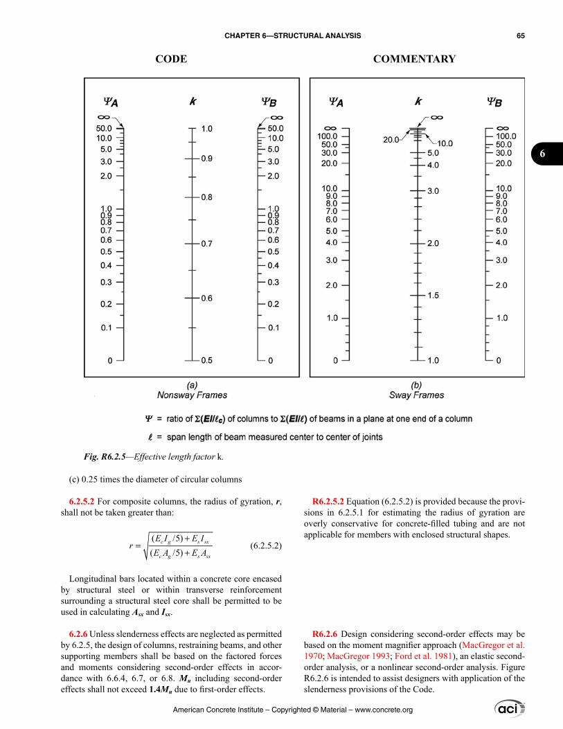
R6.2.5.2 Equation (6.2.5.2) is provided because the provi-sions in 6.2.5.1 for estimating the radius of gyration are overly conservative for concrete-filled tubing and are not applicable for members with enclosed structural shapes.
R6.2.6 Design considering second-order effects may be based on the moment magnifier approach (MacGregor et al. 1970; MacGregor 1993; Ford et al. 1981), an elastic second-order analysis, or a nonlinear second-order analysis. Figure R6.2.6 is intended to assist designers with application of the slenderness provisions of the Code.
(c) 0.25 times the diameter of circular columns
6.2.5.2 For composite columns, the radius of gyration, r, shall not be taken greater than:
( /5)( /5)
c g s sx
c g s sx
E I E Ir
E A E A+
=+
(6.2.5.2)
Longitudinal bars located within a concrete core encased by structural steel or within transverse reinforcement surrounding a structural steel core shall be permitted to be used in calculating Asx and Isx.
6.2.6 Unless slenderness effects are neglected as permitted by 6.2.5, the design of columns, restraining beams, and other supporting members shall be based on the factored forces and moments considering second-order effects in accor-dance with 6.6.4, 6.7, or 6.8. Mu including second-order effects shall not exceed 1.4Mu due to first-order effects.
Fig. R6.2.5—Effective length factor k.
American Concrete Institute – Copyrighted © Material – www.concrete.org
CHAPTER 6—STRUCTURAL ANALYSIS 65
CODE COMMENTARY
6
End moments in compression members, such as columns, walls, or braces, should be considered in the design of adja-cent flexural members. In nonsway frames, the effects of magnifying the end moments need not be considered in the design of adjacent beams. In sway frames, the magnified end moments should be considered in designing the adjoining flexural members.
Several methods have been developed to evaluate slen-derness effects in compression members subject to biaxial bending. A review of some of these methods is presented in Furlong et al. (2004).
If the weight of a structure is high in proportion to its lateral stiffness, excessive P∆ effects, where secondary moments are more than 25 percent of the primary moments, may result. The P∆ effects will eventually introduce singu-larities into the solution to the equations of equilibrium, indi-cating physical structural instability (Wilson 1997). Analyt-ical research (MacGregor and Hage 1977) on reinforced concrete frames showed that the probability of stability failure increases rapidly when the stability index Q, defined in 6.6.4.4.1, exceeds 0.2, which is equivalent to a secondary-to-primary moment ratio of 1.25. According to ASCE/SEI 7, the maximum value of the stability coefficient θ, which is close to the ACI stability coefficient Q, is 0.25. The value 0.25 is equivalent to a secondary-to-primary moment ratio of 1.33. Hence, the upper limit of 1.4 on the secondary-to-primary moment ratio was chosen.
American Concrete Institute – Copyrighted © Material – www.concrete.org
66 BUILDING CODE REQUIREMENTS FOR STRUCTURAL CONCRETE (ACI 318M-14) AND COMMENTARY (ACI 318RM-14)
CODE COMMENTARY
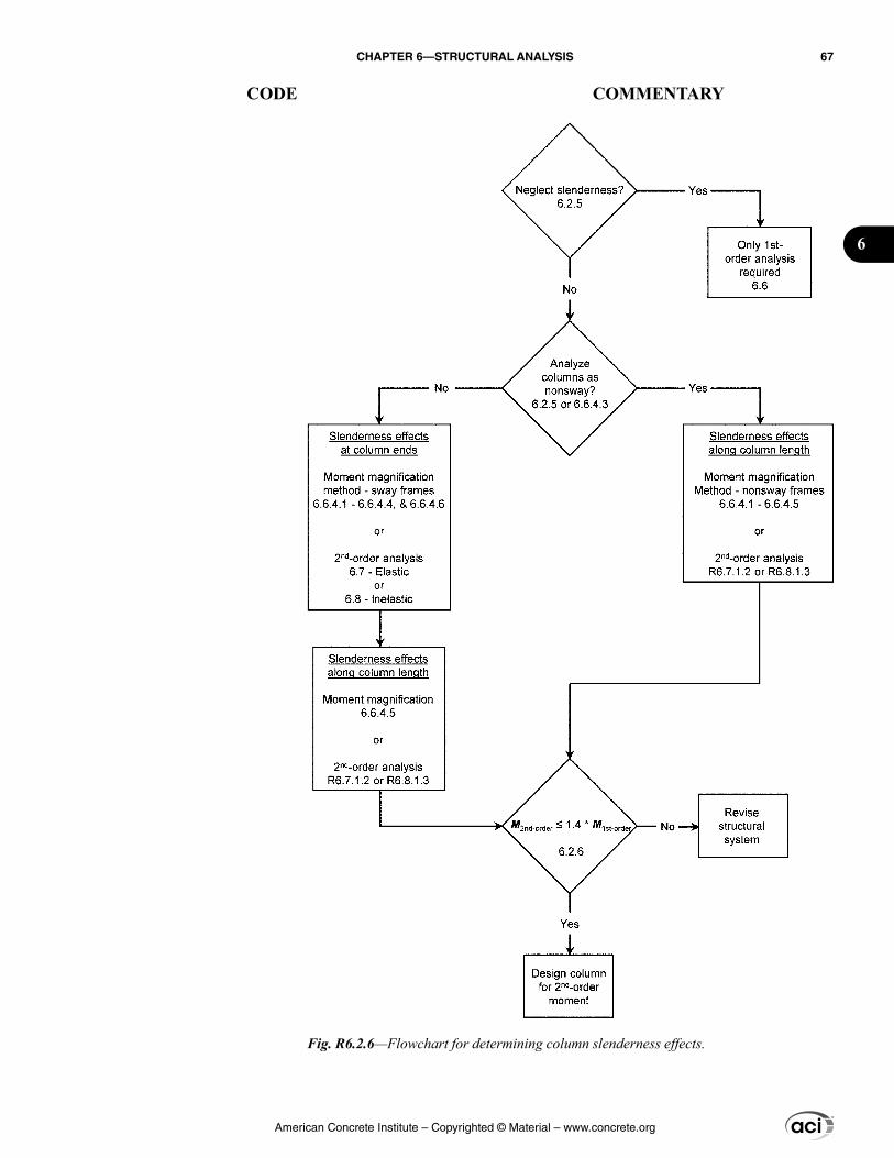
Fig. R6.2.6—Flowchart for determining column slenderness effects.
American Concrete Institute – Copyrighted © Material – www.concrete.org
CHAPTER 6—STRUCTURAL ANALYSIS 67
CODE COMMENTARY
6
6.3—Modeling assumptions 6.3.1 General
6.3.1.1 Relative stiffnesses of members within struc-tural systems shall be based on reasonable and consistent assumptions.
6.3.1.2 To calculate moments and shears caused by gravity loads in columns, beams, and slabs, it shall be permitted to use a model limited to the members in the level being considered and the columns above and below that level. It shall be permitted to assume far ends of columns built inte-grally with the structure to be fixed.
6.3.1.3 The analysis model shall consider the effects of variation of member cross-sectional properties, such as that due to haunches.
6.3.2 T-beam geometry
6.3.2.1 For nonprestressed T-beams supporting monolithic or composite slabs, the effective flange width bf shall include the beam web width bw plus an effective overhanging flange width in accordance with Table 6.3.2.1, where h is the slab thickness and sw is the clear distance to the adjacent web.
Table 6.3.2.1—Dimensional limits for effective overhanging flange width for T-beams
Flange locationEffective overhanging flange width, beyond face
of web
Each side of web Least of:
8h
sw/2
ℓn/8
One side of web Least of:
6h
sw/2
ℓn/12
R6.3—Modeling assumptions R6.3.1 General
R6.3.1.1 Ideally, the member stiffnesses EcI and GJ should reflect the degree of cracking and inelastic action that has occurred along each member before yielding. However, the complexities involved in selecting different stiffnesses for all members of a frame would make frame analyses inefficient in the design process. Simpler assumptions are required to define flexural and torsional stiffnesses.
For braced frames, relative values of stiffness are impor-tant. A common assumption is to use 0.5Ig for beams and Ig for columns.
For sway frames, a realistic estimate of I is desirable and should be used if second-order analyses are performed. Guidance for the choice of I for this case is given in 6.6.3.1.
Two conditions determine whether it is necessary to consider torsional stiffness in the analysis of a given struc-ture: 1) the relative magnitude of the torsional and flexural stiffnesses; and 2) whether torsion is required for equi-librium of the structure (equilibrium torsion) or is due to members twisting to maintain deformation compatibility (compatibility torsion). In the case of compatibility torsion, the torsional stiffness may be neglected. For cases involving equilibrium torsion, torsional stiffness should be considered.
R6.3.1.3 Stiffness and fixed-end moment coefficients for haunched members may be obtained from the Portland Cement Association (1972).
R6.3.2 T-beam geometry
R6.3.2.1 In ACI 318-11, the width of the slab effective as a T-beam flange was limited to one-fourth the span. The Code now allows one-eighth of the span on each side of the beam web. This was done to simplify Table 6.3.2.1 and has negligible impact on designs.
American Concrete Institute – Copyrighted © Material – www.concrete.org
68 BUILDING CODE REQUIREMENTS FOR STRUCTURAL CONCRETE (ACI 318M-14) AND COMMENTARY (ACI 318RM-14)
CODE COMMENTARY
6.3.2.2 Isolated nonprestressed T-beams in which the flange is used to provide additional compression area shall have a flange thickness greater than or equal to 0.5bw and an effective flange width less than or equal to 4bw.
6.3.2.3 For prestressed T-beams, it shall be permitted to use the geometry provided by 6.3.2.1 and 6.3.2.2.
6.4—Arrangement of live load 6.4.1 For the design of floors or roofs to resist gravity
loads, it shall be permitted to assume that live load is applied only to the level under consideration.
6.4.2 For one-way slabs and beams, it shall be permitted to assume (a) and (b):
(a) Maximum positive Mu near midspan occurs with factored L on the span and on alternate spans(b) Maximum negative Mu at a support occurs with factored L on adjacent spans only
6.4.3 For two-way slab systems, factored moments shall be calculated in accordance with 6.4.3.1, 6.4.3.2, or 6.4.3.3, and shall be at least the moments resulting from factored L applied simultaneously to all panels.
6.4.3.1 If the arrangement of L is known, the slab system shall be analyzed for that arrangement.
6.4.3.2 If L is variable and does not exceed 0.75D, or the nature of L is such that all panels will be loaded simultane-ously, it shall be permitted to assume that maximum Mu at all sections occurs with factored L applied simultaneously to all panels.
6.4.3.3 For loading conditions other than those defined in 6.4.3.1 or 6.4.3.2, it shall be permitted to assume (a) and (b):
(a) Maximum positive Mu near midspan of panel occurs with 75 percent of factored L on the panel and alternate panels(b) Maximum negative Mu at a support occurs with 75 percent of factored L on adjacent panels only
R6.3.2.3 The empirical provisions of 6.3.2.1 and 6.3.2.2 were developed for nonprestressed T-beams. The flange widths in 6.3.2.1 and 6.3.2.2 should be used unless expe-rience has proven that variations are safe and satisfactory. Although many standard prestressed products in use today do not satisfy the effective flange width requirements of 6.3.2.1 and 6.3.2.2, they demonstrate satisfactory performance. Therefore, determination of an effective flange width for prestressed T-beams is left to the experience and judgment of the licensed design professional. It is not always considered conservative in elastic analysis and design considerations to use the maximum flange width as permitted in 6.3.2.1.
R6.4—Arrangement of live load
R6.4.2 The most demanding sets of design forces should be established by investigating the effects of live load placed in various critical patterns.
R6.4.3.3 The use of only 75 percent of the full factored live load for maximum moment loading patterns is based on the fact that maximum negative and maximum positive live load moments cannot occur simultaneously and that redistribution of maximum moments is thus possible before failure occurs. This procedure, in effect, permits some local overstress under the full factored live load if it is distributed in the prescribed manner, but still ensures that the design strength of the slab system after redistribution of moment is not less than that required to resist the full factored dead and live loads on all panels.
American Concrete Institute – Copyrighted © Material – www.concrete.org
CHAPTER 6—STRUCTURAL ANALYSIS 69
CODE COMMENTARY
6
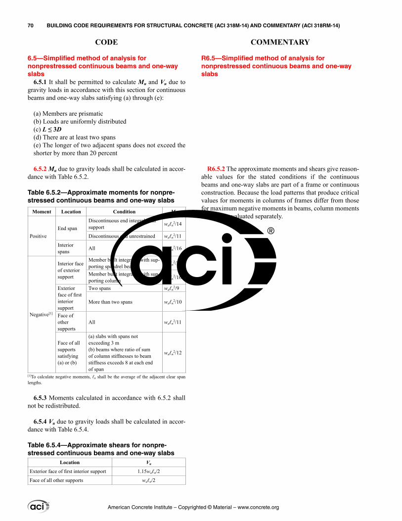
6.5—Simplified method of analysis for nonprestressed continuous beams and one-way slabs
6.5.1 It shall be permitted to calculate Mu and Vu due to gravity loads in accordance with this section for continuous beams and one-way slabs satisfying (a) through (e):
(a) Members are prismatic(b) Loads are uniformly distributed(c) L ≤ 3D(d) There are at least two spans(e) The longer of two adjacent spans does not exceed the shorter by more than 20 percent
6.5.2 Mu due to gravity loads shall be calculated in accor-dance with Table 6.5.2.
Table 6.5.2—Approximate moments for nonpre-stressed continuous beams and one-way slabs
Moment Location Condition Mu
PositiveEnd span
Discontinuous end integral with support wuℓn
2/14
Discontinuous end unrestrained wuℓn2/11
Interior spans All wuℓn
2/16
Negative[1]
Interior face of exterior support
Member built integrally with sup-porting spandrel beam wuℓn
2/24
Member built integrally with sup-porting column wuℓn
2/16
Exterior face of first interior support
Two spans wuℓn2/9
More than two spans wuℓn2/10
Face of other supports
All wuℓn2/11
Face of all supports satisfying (a) or (b)
(a) slabs with spans not exceeding 3 m(b) beams where ratio of sum of column stiffnesses to beam stiffness exceeds 8 at each end of span
wuℓn2/12
[1]To calculate negative moments, ℓn shall be the average of the adjacent clear span lengths.
6.5.3 Moments calculated in accordance with 6.5.2 shall not be redistributed.
6.5.4 Vu due to gravity loads shall be calculated in accor-dance with Table 6.5.4.
Table 6.5.4—Approximate shears for nonpre-stressed continuous beams and one-way slabs
Location Vu
Exterior face of first interior support 1.15wuℓn/2
Face of all other supports wuℓn/2
R6.5—Simplified method of analysis for nonprestressed continuous beams and one-way slabs
R6.5.2 The approximate moments and shears give reason-able values for the stated conditions if the continuous beams and one-way slabs are part of a frame or continuous construction. Because the load patterns that produce critical values for moments in columns of frames differ from those for maximum negative moments in beams, column moments should be evaluated separately.
American Concrete Institute – Copyrighted © Material – www.concrete.org
70 BUILDING CODE REQUIREMENTS FOR STRUCTURAL CONCRETE (ACI 318M-14) AND COMMENTARY (ACI 318RM-14)
CODE COMMENTARY
6.5.5 Floor or roof level moments shall be resisted by distributing the moment between columns immediately above and below the given floor in proportion to the relative column stiffnesses considering conditions of restraint.
6.6—First-order analysis 6.6.1 General
6.6.1.1 Slenderness effects shall be considered in accor-dance with 6.6.4, unless they are allowed to be neglected by 6.2.5.
6.6.1.2 Redistribution of moments calculated by an elastic first-order analysis shall be permitted in accordance with 6.6.5.
6.6.2 Modeling of members and structural systems
6.6.2.1 Floor or roof level moments shall be resisted by distributing the moment between columns immediately above and below the given floor in proportion to the relative column stiffnesses and considering conditions of restraint.
6.6.2.2 For frames or continuous construction, consid-eration shall be given to the effect of floor and roof load patterns on transfer of moment to exterior and interior columns, and of eccentric loading due to other causes.
6.6.2.3 It shall be permitted to simplify the analysis model by the assumptions of (a), (b), or both:
(a) Solid slabs or one-way joist systems built integrally with supports, with clear spans not more than 3 m, shall be permitted to be analyzed as continuous members on knife-edge supports with spans equal to the clear spans of the member and width of support beams otherwise neglected.(b) For frames or continuous construction, it shall be permitted to assume the intersecting member regions are rigid.
6.6.3 Section properties
6.6.3.1 Factored load analysis
R6.5.5 This section is provided to make certain that moments are included in column design. The moment refers to the difference between the end moments of the members framing into the column and exerted at the column centerline.
R6.6—First-order analysis R6.6.1 General
R6.6.1.1 When using first-order analysis, slenderness effects are calculated using the moment magnifier approach (MacGregor et al. 1970; MacGregor 1993; Ford et al. 1981).
R6.6.2 Modeling of members and structural systems
R6.6.2.1 This section is provided to make certain that moments are included in column design if members have been proportioned using 6.5.1 and 6.5.2. The moment refers to the difference between the end moments of the members framing into the column and exerted at the column centerline.
R6.6.2.3 A common feature of modern frame analysis software is the assumption of rigid connections. Section 6.6.2.3(b) is intended to apply to intersecting elements in frames, such as beam-column joints.
R6.6.3 Section properties
R6.6.3.1 Factored load analysis—For lateral load anal-ysis, either the stiffnesses presented in 6.6.3.1.1 or 6.6.3.1.2 can be used. These provisions both use values that approxi-mate the stiffness for reinforced concrete building systems loaded to near or beyond the yield level, and have been shown to produce reasonable correlation with both experimental and detailed analytical results (Moehle 1992; Lepage 1998). For earthquake-induced loading, the use of 6.6.3.1.1 or 6.6.3.1.2 may require a deflection amplification factor to account for inelastic deformations. In general, for effective section proper-ties, Ec may be defined as in 19.2.2, A as in Table 6.6.3.1.1(a), and the shear modulus may be taken as 0.4Ec.
American Concrete Institute – Copyrighted © Material – www.concrete.org
CHAPTER 6—STRUCTURAL ANALYSIS 71
CODE COMMENTARY
6
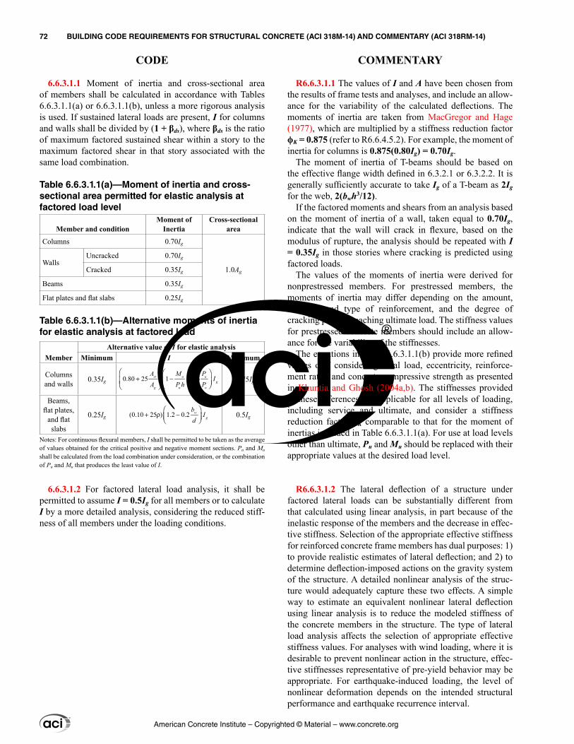
6.6.3.1.1 Moment of inertia and cross-sectional area of members shall be calculated in accordance with Tables 6.6.3.1.1(a) or 6.6.3.1.1(b), unless a more rigorous analysis is used. If sustained lateral loads are present, I for columns and walls shall be divided by (1 + βds), where βds is the ratio of maximum factored sustained shear within a story to the maximum factored shear in that story associated with the same load combination.
Table 6.6.3.1.1(a)—Moment of inertia and cross-sectional area permitted for elastic analysis at factored load level
Member and conditionMoment of
InertiaCross-sectional
area
Columns 0.70Ig
1.0Ag
WallsUncracked 0.70Ig
Cracked 0.35Ig
Beams 0.35Ig
Flat plates and flat slabs 0.25Ig
Table 6.6.3.1.1(b)—Alternative moments of inertia for elastic analysis at factored load
MemberAlternative value of I for elastic analysis
Minimum I Maximum
Columns and walls 0.35Ig 0.80 25 1 0.5st u u
gg u o
A M PI
A P h P+ − −
0.875Ig
Beams, flat plates,
and flat slabs
0.25Ig (0.10 25 ) 1.2 0.2 wg
bI
d+ ρ −
0.5Ig
Notes: For continuous flexural members, I shall be permitted to be taken as the average of values obtained for the critical positive and negative moment sections. Pu and Mu shall be calculated from the load combination under consideration, or the combination of Pu and Mu that produces the least value of I.
6.6.3.1.2 For factored lateral load analysis, it shall be permitted to assume I = 0.5Ig for all members or to calculate I by a more detailed analysis, considering the reduced stiff-ness of all members under the loading conditions.
R6.6.3.1.1 The values of I and A have been chosen from the results of frame tests and analyses, and include an allow-ance for the variability of the calculated deflections. The moments of inertia are taken from MacGregor and Hage (1977), which are multiplied by a stiffness reduction factor ϕK = 0.875 (refer to R6.6.4.5.2). For example, the moment of inertia for columns is 0.875(0.80Ig) = 0.70Ig.
The moment of inertia of T-beams should be based on the effective flange width defined in 6.3.2.1 or 6.3.2.2. It is generally sufficiently accurate to take Ig of a T-beam as 2Ig for the web, 2(bwh3/12).
If the factored moments and shears from an analysis based on the moment of inertia of a wall, taken equal to 0.70Ig, indicate that the wall will crack in flexure, based on the modulus of rupture, the analysis should be repeated with I = 0.35Ig in those stories where cracking is predicted using factored loads.
The values of the moments of inertia were derived for nonprestressed members. For prestressed members, the moments of inertia may differ depending on the amount, location, and type of reinforcement, and the degree of cracking prior to reaching ultimate load. The stiffness values for prestressed concrete members should include an allow-ance for the variability of the stiffnesses.
The equations in Table 6.6.3.1.1(b) provide more refined values of I considering axial load, eccentricity, reinforce-ment ratio, and concrete compressive strength as presented in Khuntia and Ghosh (2004a,b). The stiffnesses provided in these references are applicable for all levels of loading, including service and ultimate, and consider a stiffness reduction factor ϕK comparable to that for the moment of inertias included in Table 6.6.3.1.1(a). For use at load levels other than ultimate, Pu and Mu should be replaced with their appropriate values at the desired load level.
R6.6.3.1.2 The lateral deflection of a structure under factored lateral loads can be substantially different from that calculated using linear analysis, in part because of the inelastic response of the members and the decrease in effec-tive stiffness. Selection of the appropriate effective stiffness for reinforced concrete frame members has dual purposes: 1) to provide realistic estimates of lateral deflection; and 2) to determine deflection-imposed actions on the gravity system of the structure. A detailed nonlinear analysis of the struc-ture would adequately capture these two effects. A simple way to estimate an equivalent nonlinear lateral deflection using linear analysis is to reduce the modeled stiffness of the concrete members in the structure. The type of lateral load analysis affects the selection of appropriate effective stiffness values. For analyses with wind loading, where it is desirable to prevent nonlinear action in the structure, effec-tive stiffnesses representative of pre-yield behavior may be appropriate. For earthquake-induced loading, the level of nonlinear deformation depends on the intended structural performance and earthquake recurrence interval.
American Concrete Institute – Copyrighted © Material – www.concrete.org
72 BUILDING CODE REQUIREMENTS FOR STRUCTURAL CONCRETE (ACI 318M-14) AND COMMENTARY (ACI 318RM-14)
CODE COMMENTARY
6.6.3.1.3 For factored lateral load analysis of two-way slab systems without beams, which are designated as part of the seismic-force-resisting system, I for slab members shall be defined by a model that is in substantial agreement with results of comprehensive tests and analysis and I of other frame members shall be in accordance with 6.6.3.1.1 and 6.6.3.1.2.
6.6.3.2 Service load analysis
6.6.3.2.1 Immediate and time-dependent deflections due to gravity loads shall be calculated in accordance with 24.2.
6.6.3.2.2 It shall be permitted to calculate immediate lateral deflections using a moment of inertia of 1.4 times I defined in 6.6.3.1, or using a more detailed analysis, but the value shall not exceed Ig.
6.6.4 Slenderness effects, moment magnification method
6.6.4.1 Unless 6.2.5 is satisfied, columns and stories in structures shall be designated as being nonsway or sway. Analysis of columns in nonsway frames or stories shall be in accordance with 6.6.4.5. Analysis of columns in sway frames or stories shall be in accordance with 6.6.4.6.
Varying degrees of confidence can be obtained from a simple linear analysis based on the computational rigor used to define the effective stiffness of each member. A reduced stiffness can be based on the secant stiffness to a point at or beyond yield or, if yielding is not expected, to a point before yield occurs.
R6.6.3.1.3 Analysis of buildings with two-way slab systems without beams requires that the model represents the transfer of lateral loads between vertical members. The model should result in prediction of stiffness in substantial agreement with results of comprehensive tests and analysis. Several acceptable models have been proposed to accom-plish this objective (Vanderbilt and Corley 1983; Hwang and Moehle 2000; Dovich and Wight 2005).
R6.6.3.2 Service load analysis
R6.6.3.2.2 Analyses of deflections, vibrations, and building periods are needed at various service (unfactored) load levels (Grossman 1987, 1990) to determine the perfor-mance of the structure in service. The moments of inertia of the structural members in the service load analyses should be representative of the degree of cracking at the various service load levels investigated. Unless a more accurate estimate of the degree of cracking at service load level is available, it is satisfactory to use 1.0/0.70 = 1.4 times the moments of inertia provided in 6.6.3.1, not to exceed Ig, for service load analyses.
R6.6.4 Slenderness effects, moment magnification method
R6.6.4.1 This section describes an approximate design procedure that uses the moment magnifier concept to account for slenderness effects. Moments calculated using a first-order frame analysis are multiplied by a moment magnifier that is a function of the factored axial load Pu and the crit-ical buckling load Pc for the column. For the sway case, the moment magnifier is a function of the sum of Pu of the story and the sum of Pc of the sway-resisting columns in the story considered. Nonsway and sway frames are treated sepa-rately. A first-order frame analysis is an elastic analysis that excludes the internal force effects resulting from deflections.
The moment magnifier design method requires the designer to distinguish between nonsway frames, which are designed according to 6.6.4.5, and sway frames, which are designed according to 6.6.4.6. Frequently this can be done by comparing the total lateral stiffness of the columns in a story to that of the bracing elements. A compression member, such as a column, wall, or brace, may be assumed nonsway if it is located in a story in which the bracing elements (shear walls, shear trusses, or other types of lateral bracing) have such substantial lateral stiffness to resist the lateral deflec-
American Concrete Institute – Copyrighted © Material – www.concrete.org
CHAPTER 6—STRUCTURAL ANALYSIS 73
CODE COMMENTARY
6
6.6.4.2 The cross-sectional dimensions of each member used in an analysis shall be within 10 percent of the specified member dimensions in construction documents or the anal-ysis shall be repeated. If the stiffnesses of Table 6.6.3.1.1(b) are used in an analysis, the assumed member reinforcement ratio shall also be within 10 percent of the specified member reinforcement in construction documents.
6.6.4.3 It shall be permitted to analyze columns and stories in structures as nonsway frames if (a) or (b) is satisfied:
(a) The increase in column end moments due to second-order effects does not exceed 5 percent of the first-order end moments(b) Q in accordance with 6.6.4.4.1 does not exceed 0.05
6.6.4.4 Stability properties
6.6.4.4.1 The stability index for a story, Q, shall be calcu-lated by:
u o
us c
PQ
VΣ ∆
=l
(6.6.4.4.1)
where ∑Pu and Vus are the total factored vertical load and horizontal story shear, respectively, in the story being eval-uated, and ∆o is the first-order relative lateral deflection between the top and the bottom of that story due to Vus.
6.6.4.4.2 The critical buckling load Pc shall be calculated by:
2
2
( )( )
effc
u
EIP
kπ
=l
(6.6.4.4.2)
6.6.4.4.3 The effective length factor k shall be calculated using Ec in accordance with 19.2.2 and I in accordance with 6.6.3.1.1. For nonsway members, k shall be permitted to be taken as 1.0, and for sway members, k shall be at least 1.0.
tions of the story that any resulting lateral deflection is not large enough to affect the column strength substantially. If not readily apparent without calculations, 6.6.4.3 provides two possible ways of determining if sway can be neglected.
R6.6.4.3 In 6.6.4.3(a), a story in a frame is classified as nonsway if the increase in the lateral load moments resulting from P∆ effects does not exceed 5 percent of the first-order moments (MacGregor and Hage 1977). Section 6.6.4.3(b) provides an alternative method of determining if a frame is classified as nonsway based on the stability index for a story, Q. In calculating Q, ∑Pu should correspond to the lateral loading case for which ∑Pu is greatest. A frame may contain both nonsway and sway stories.
If the lateral load deflections of the frame are calculated using service loads and the service load moments of inertia given in 6.6.3.2.2, it is permissible to calculate Q in Eq. (6.6.4.4.1) using 1.2 times the sum of the service gravity loads, the service load story shear, and 1.4 times the first-order service load story deflections.
R6.6.4.4 Stability properties
R6.6.4.4.2 In calculating the critical axial buckling load, the primary concern is the choice of a stiffness (EI)eff that reasonably approximates the variations in stiffness due to cracking, creep, and nonlinearity of the concrete stress-strain curve. Sections 6.6.4.4.4 and 6.6.4.4.5 may be used to calculate (EI)eff.
R6.6.4.4.3 The effective length factor for a compres-sion member, such as a column, wall, or brace, considering braced behavior, ranges from 0.5 to 1.0. It is recommended that a k value of 1.0 be used. If lower values are used, the calculation of k should be based on analysis of the frame using I values given in 6.6.3.1.1. The Jackson and More-
American Concrete Institute – Copyrighted © Material – www.concrete.org
74 BUILDING CODE REQUIREMENTS FOR STRUCTURAL CONCRETE (ACI 318M-14) AND COMMENTARY (ACI 318RM-14)
CODE COMMENTARY
6.6.4.4.4 For noncomposite columns, (EI)eff shall be calculated in accordance with (a), (b), or (c):
(a) 0.4
( )1
c geff
dns
E IEI =
+ β (6.6.4.4.4a)
(b) (0.2 )
( )1
c g s seeff
dns
E I E IEI
+=
+ β (6.6.4.4.4b)
(c) ( )1
ceff
dns
E IEI =
+ β (6.6.4.4.4c)
where βdns shall be the ratio of maximum factored sustained axial load to maximum factored axial load associated with the same load combination and I in Eq. (6.6.4.4.4c) is calcu-lated according to Table 6.6.3.1.1(b) for columns and walls.
6.6.4.4.5 For composite columns, (EI)eff shall be calcu-lated by Eq. (6.6.4.4.4b), Eq. (6.6.4.4.5), or from a more detailed analysis.
( )0.2
( )1
c geff s sx
dns
E IEI E I= +
+ β (6.6.4.4.5)
6.6.4.5 Moment magnification method: Nonsway frames
6.6.4.5.1 The factored moment used for design of columns and walls, Mc, shall be the first-order factored moment M2 amplified for the effects of member curvature.
Mc = δM2 (6.6.4.5.1)
6.6.4.5.2 Magnification factor δ shall be calculated by:
1.01
0.75
m
u
c
CP
P
δ = ≥−
(6.6.4.5.2)
land Alignment Charts (Fig. R6.2.5) can be used to estimate appropriate values of k (ACI SP-17(09); Column Research Council 1966).
R6.6.4.4.4 The numerators of Eq. (6.6.4.4.4a) to (6.6.4.4.4c) represent the short-term column stiffness. Equa-tion (6.6.4.4.4b) was derived for small eccentricity ratios and high levels of axial load. Equation (6.6.4.4.4a) is a simplified approximation to Eq. (6.6.4.4.4b) and is less accurate (Mirza 1990). For improved accuracy, (EI)eff can be approximated using Eq. (6.6.4.4.4c).
Creep due to sustained loads will increase the lateral deflections of a column and, hence, the moment magnifica-tion. Creep effects are approximated in design by reducing the stiffness (EI)eff used to calculate Pc and, hence, δ, by dividing the short-term EI provided by the numerator of Eq. (6.6.4.4.4a) through (6.6.4.4.4c) by (1 + βdns). For simpli-fication, it can be assumed that βdns = 0.6. In this case, Eq. (6.6.4.4.4a) becomes (EI)eff = 0.25EcIg.
In reinforced concrete columns subject to sustained loads, creep transfers some of the load from the concrete to the longitudinal reinforcement, increasing the reinforcement stresses. In the case of lightly reinforced columns, this load transfer may cause the compression reinforcement to yield prematurely, resulting in a loss in the effective EI. Accord-ingly, both the concrete and longitudinal reinforcement terms in Eq. (6.6.4.4.4b) are reduced to account for creep.
R6.6.4.4.5 For composite columns in which the pipe or structural shape makes up a large percentage of the cross section, the load transfer due to creep is insignificant. Accordingly, only the EI of the concrete in Eq. (6.6.4.4.5) is reduced for sustained load effects.
R6.6.4.5 Moment magnification method: Nonsway frames
R6.6.4.5.2 The 0.75 factor in Eq. (6.6.4.5.2) is the stiff-ness reduction factor ϕK, which is based on the probability of understrength of a single isolated slender column. Studies reported in Mirza et al. (1987) indicate that the stiffness reduction factor ϕK and the cross-sectional strength reduc-tion ϕ factors do not have the same values. These studies suggest the stiffness reduction factor ϕK for an isolated column should be 0.75 for both tied and spiral columns. In the case of a multistory frame, the column and frame deflections depend on the average concrete strength, which is higher than the strength of the concrete in the critical
American Concrete Institute – Copyrighted © Material – www.concrete.org
CHAPTER 6—STRUCTURAL ANALYSIS 75
CODE COMMENTARY
6
6.6.4.5.3 Cm shall be in accordance with (a) or (b):
(a) For columns without transverse loads applied between supports
1
2
0.6 0.4mM
CM
= − (6.6.4.5.3a)
where M1/M2 is negative if the column is bent in single curvature, and positive if bent in double curvature. M1 corresponds to the end moment with the lesser absolute value.(b) For columns with transverse loads applied between supports.
Cm = 1.0 (6.6.4.5.3b)
6.6.4.5.4 M2 in Eq. (6.6.4.5.1) shall be at least M2,min calcu-lated according to Eq. (6.6.4.5.4) about each axis separately.
M2,min = Pu(15 + 0.03h) (6.6.4.5.4)
If M2,min exceeds M2, Cm shall be taken equal to 1.0 or calculated based on the ratio of the calculated end moments M1/M2, using Eq. (6.6.4.5.3a).
6.6.4.6 Moment magnification method: Sway frames
6.6.4.6.1 Moments M1 and M2 at the ends of an individual column shall be calculated by (a) and (b).
(a) M1 = M1ns + δsM1s (6.6.4.6.1a)
(b) M2 = M2ns + δsM2s (6.6.4.6.1b)
6.6.4.6.2 The moment magnifier δs shall be calculated by (a), (b), or (c). If δs exceeds 1.5, only (b) or (c) shall be permitted:
(a) 1 11s Q
δ = ≥−
(6.6.4.6.2a)
single understrength column. For this reason, the value of ϕK implicit in I values in 6.6.3.1.1 is 0.875.
R6.6.4.5.3 The factor Cm is a correction factor relating the actual moment diagram to an equivalent uniform moment diagram. The derivation of the moment magnifier assumes that the maximum moment is at or near midheight of the column. If the maximum moment occurs at one end of the column, design should be based on an equivalent uniform moment CmM2 that leads to the same maximum moment at or near midheight of the column when magnified (MacGregor et al. 1970).
The sign convention for M1/M2 has been updated to follow the right hand rule convention; hence, M1/M2 is negative if bent in single curvature and positive if bent in double curva-ture. This reflects a sign convention change from the 2011 Code.
In the case of columns that are subjected to transverse loading between supports, it is possible that the maximum moment will occur at a section away from the end of the member. If this occurs, the value of the largest calculated moment occurring anywhere along the member should be used for the value of M2 in Eq. (6.6.4.5.1). Cm is to be taken as 1.0 for this case.
R6.6.4.5.4 In the Code, slenderness is accounted for by magnifying the column end moments. If the factored column moments are small or zero, the design of slender columns should be based on the minimum eccentricity provided in Eq. (6.6.4.5.4). It is not intended that the minimum eccen-tricity be applied about both axes simultaneously.
The factored column end moments from the struc-tural analysis are used in Eq. (6.6.4.5.3a) in determining the ratio M1/M2 for the column when the design is based on the minimum eccentricity. This eliminates what would otherwise be a discontinuity between columns with calcu-lated eccentricities less than the minimum eccentricity and columns with calculated eccentricities equal to or greater than the minimum eccentricity.
R6.6.4.6 Moment magnification method: Sway frames
R6.6.4.6.1 The analysis described in this section deals only with plane frames subjected to loads causing deflections in that plane. If the lateral load deflections involve significant torsional displacement, the moment magnification in the columns farthest from the center of twist may be underesti-mated by the moment magnifier procedure. In such cases, a three-dimensional second-order analysis should be used.
R6.6.4.6.2 Three different methods are allowed for calcu-lating the moment magnifier. These approaches include the Q method, the sum of P concept, and second-order elastic analysis.
(a) Q method:
American Concrete Institute – Copyrighted © Material – www.concrete.org
76 BUILDING CODE REQUIREMENTS FOR STRUCTURAL CONCRETE (ACI 318M-14) AND COMMENTARY (ACI 318RM-14)
CODE COMMENTARY
(b) 1 11
0.75
su
c
PP
δ = ≥Σ−
Σ
(6.6.4.6.2b)
(c) Second-order elastic analysis
where ∑Pu is the summation of all the factored vertical loads in a story and ∑Pc is the summation for all sway-resisting columns in a story. Pc is calculated using Eq. (6.6.4.4.2) with k determined for sway members from 6.6.4.4.3 and (EI)eff from 6.6.4.4.4 or 6.6.4.4.5 as appropriate with βds substituted for βdns.
The iterative P∆ analysis for second-order moments can be represented by an infinite series. The solution of this series is given by Eq. (6.6.4.6.2a) (MacGregor and Hage 1977). Lai and MacGregor (1983) show that Eq. (6.6.4.6.2a) closely predicts the second-order moments in a sway frame until δs exceeds 1.5. The P∆ moment diagrams for deflected columns are curved, with ∆ related to the deflected shape of the columns. Equation (6.6.4.6.2a) and most commer-cially available second-order frame analyses have been derived assuming that the P∆ moments result from equal and opposite forces of P∆/ℓc applied at the bottom and top of the story. These forces give a straight-line P∆ moment diagram. The curved P∆ moment diagrams lead to lateral displacements on the order of 15 percent larger than those from the straight-line P∆ moment diagrams. This effect can be included in Eq. (6.6.4.6.2a) by writing the denominator as (1 – 1.15Q) rather than (1 – Q). The 1.15 factor has been omitted from Eq. (6.6.4.6.2a) for simplicity. If deflections have been calculated using service loads, Q in Eq. (6.6.4.6.2a) should be calculated in the manner explained in R6.6.4.3. The Q factor analysis is based on deflections calcu-lated using the I values from 6.6.3.1.1, which include the equivalent of a stiffness reduction factor ϕK. These I values lead to a 20 to 25 percent over-estimation of the lateral deflections that corresponds to a stiffness reduc-tion factor ϕK between 0.80 and 0.85 on the P∆ moments. As a result, no additional ϕ factor is needed. Once the moments are established using Eq. (6.6.4.6.2a), selec-tion of the cross sections of the columns involves the strength reduction factors ϕ from 21.2.2.
(b) Sum of P concept: To check the effects of story stability, δs is calcu-lated as an averaged value for the entire story based on use of ∑Pu/∑Pc. This reflects the interaction of all sway-resisting columns in the story on the P∆ effects because the lateral deflection of all columns in the story should be equal in the absence of torsional displace-ments about a vertical axis. In addition, it is possible that a particularly slender individual column in a sway frame could have substantial midheight deflections, even if adequately braced against lateral end deflections by other columns in the story. Such a column is checked using 6.6.4.6.4. The 0.75 in the denominator of Eq. (6.6.4.6.2b) is a stiffness reduction factor ϕK, as explained in R6.6.4.5.2.In the calculation of (EI)eff, βds will normally be zero for a sway frame because the lateral loads are generally of short duration. Sway deflections due to short-term loads, such as wind or earthquake, are a function of the short-term stiffness of the columns following a period of sustained gravity load. For this case, the definition of βds in 6.6.3.1.1 gives βds = 0. In the unusual case of a sway frame where the
American Concrete Institute – Copyrighted © Material – www.concrete.org
CHAPTER 6—STRUCTURAL ANALYSIS 77
CODE COMMENTARY
6
6.6.4.6.3 Flexural members shall be designed for the total magnified end moments of the columns at the joint.
6.6.4.6.4 Second-order effects shall be considered along the length of columns in sway frames. It shall be permitted to account for these effects using 6.6.4.5, where Cm is calcu-lated using M1 and M2 from 6.6.4.6.1.
6.6.5 Redistribution of moments in continuous flexural members
6.6.5.1 Except where approximate values for moments are used in accordance with 6.5, where moments have been calculated in accordance with 6.8, or where moments in two-way slabs are determined using pattern loading speci-fied in 6.4.3.3, reduction of moments at sections of maximum negative or maximum positive moment calculated by elastic theory shall be permitted for any assumed loading arrange-ment if (a) and (b) are satisfied:
(a) Flexural members are continuous(b) εt ≥ 0.0075 at the section at which moment is reduced
6.6.5.2 For prestressed members, moments include those due to factored loads and those due to reactions induced by prestressing.
6.6.5.3 At the section where the moment is reduced, redis-tribution shall not exceed the lesser of 1000εt percent and 20 percent.
6.6.5.4 The reduced moment shall be used to calculate redistributed moments at all other sections within the spans such that static equilibrium is maintained after redistribution of moments for each loading arrangement.
6.6.5.5 Shears and support reactions shall be calculated in accordance with static equilibrium considering the redistrib-uted moments for each loading arrangement.
lateral loads are sustained, βds will not be zero. This might occur if a building on a sloping site is subjected to earth pressure on one side but not on the other.
R6.6.4.6.3 The strength of a sway frame is governed by stability of the columns and the degree of end restraint provided by the beams in the frame. If plastic hinges form in the restraining beam, as the structure approaches a failure mechanism, its axial strength is drastically reduced. This section requires the restraining flexural members to have enough strength to resist the total magnified column end moments at the joint.
R6.6.4.6.4 The maximum moment in a compression member, such as a column, wall, or brace, may occur between its ends. While second-order computer analysis programs may be used to evaluate magnification of the end moments, magnification between the ends may not be accounted for unless the member is subdivided along its length. The magnification may be evaluated using the proce-dure outlined in 6.6.4.5.
R6.6.5 Redistribution of moments in continuous flexural members—Redistribution of moments is dependent on adequate ductility in plastic hinge regions. These plastic hinge regions develop at sections of maximum positive or negative moment and cause a shift in the elastic moment diagram. The usual result is a reduction in the values of maximum negative moments in the support regions and an increase in the values of positive moments between supports from those calculated by elastic analysis. However, because negative moments are typically determined for one loading arrange-ment and positive moments for another (6.4.3 provides an exception for certain loading conditions), economies in rein-forcement can sometimes be realized by reducing maximum elastic positive moments and increasing negative moments, thus narrowing the envelope of maximum negative and positive moments at any section in the span (Bondy 2003). Plastic hinges permit utilization of the full capacity of more cross sections of a flexural member at ultimate loads.
The Code permissible redistribution is shown in Fig. R6.6.5. Using conservative values of limiting concrete strains and lengths of plastic hinges derived from extensive tests, flexural members with small rotation capacities were analyzed for redistribution of moments up to 20 percent, depending on the reinforcement ratio. As shown, the permis-sible redistribution percentages are conservative relative to the calculated percentages available for both fy = 420 MPa and 550 MPa. Studies by Cohn (1965) and Mattock (1959) support this conclusion and indicate that cracking and deflec-tion of beams designed for redistribution of moments are not significantly greater at service loads than for beams designed by the distribution of moments according to elastic theory. Also, these studies indicate that adequate rotational capacity for the redistribution of moments allowed by the Code is available if the members satisfy 6.6.5.1.
American Concrete Institute – Copyrighted © Material – www.concrete.org
78 BUILDING CODE REQUIREMENTS FOR STRUCTURAL CONCRETE (ACI 318M-14) AND COMMENTARY (ACI 318RM-14)
CODE COMMENTARY
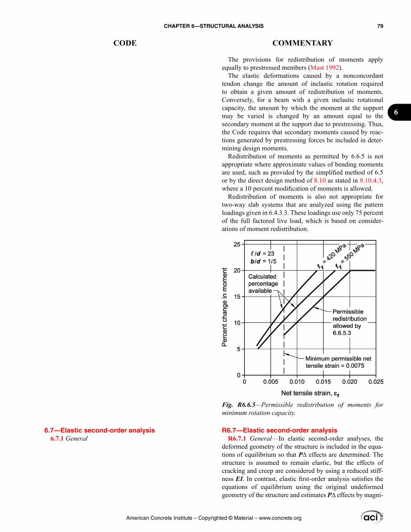
6.7—Elastic second-order analysis 6.7.1 General
The provisions for redistribution of moments apply equally to prestressed members (Mast 1992).
The elastic deformations caused by a nonconcordant tendon change the amount of inelastic rotation required to obtain a given amount of redistribution of moments. Conversely, for a beam with a given inelastic rotational capacity, the amount by which the moment at the support may be varied is changed by an amount equal to the secondary moment at the support due to prestressing. Thus, the Code requires that secondary moments caused by reac-tions generated by prestressing forces be included in deter-mining design moments.
Redistribution of moments as permitted by 6.6.5 is not appropriate where approximate values of bending moments are used, such as provided by the simplified method of 6.5 or by the direct design method of 8.10 as stated in 8.10.4.3, where a 10 percent modification of moments is allowed.
Redistribution of moments is also not appropriate for two-way slab systems that are analyzed using the pattern loadings given in 6.4.3.3. These loadings use only 75 percent of the full factored live load, which is based on consider-ations of moment redistribution.
R6.7—Elastic second-order analysis R6.7.1 General—In elastic second-order analyses, the
deformed geometry of the structure is included in the equa-tions of equilibrium so that P∆ effects are determined. The structure is assumed to remain elastic, but the effects of cracking and creep are considered by using a reduced stiff-ness EI. In contrast, elastic first-order analysis satisfies the equations of equilibrium using the original undeformed geometry of the structure and estimates P∆ effects by magni-
Fig. R6.6.5—Permissible redistribution of moments for minimum rotation capacity.
American Concrete Institute – Copyrighted © Material – www.concrete.org
CHAPTER 6—STRUCTURAL ANALYSIS 79
CODE COMMENTARY
6
6.7.1.1 An elastic second-order analysis shall consider the influence of axial loads, presence of cracked regions along the length of the member, and effects of load duration. These considerations are satisfied using the cross-sectional proper-ties defined in 6.7.2.
6.7.1.2 Slenderness effects along the length of a column shall be considered. It shall be permitted to calculate these effects using 6.6.4.5.
6.7.1.3 The cross-sectional dimensions of each member used in an analysis to calculate slenderness effects shall be within 10 percent of the specified member dimensions in construction documents or the analysis shall be repeated.
6.7.1.4 Redistribution of moments calculated by an elastic second-order analysis shall be permitted in accordance with 6.6.5.
6.7.2 Section properties
6.7.2.1 Factored load analysis
6.7.2.1.1 It shall be permitted to use section properties calculated in accordance with 6.6.3.1.
6.7.2.2 Service load analysis
6.7.2.2.1 Immediate and time-dependent deflections due to gravity loads shall be calculated in accordance with 24.2.
fying the column-end sway moments using Eq. (6.6.4.6.2a) or (6.6.4.6.2b).
R6.7.1.1 The stiffnesses EI used in an analysis for strength design should represent the stiffnesses of the members immediately prior to failure. This is particularly true for a second-order analysis that should predict the lateral deflec-tions at loads approaching ultimate. The EI values should not be based solely on the moment-curvature relationship for the most highly loaded section along the length of each member. Instead, they should correspond to the moment-end rotation relationship for a complete member.
To allow for variability in the actual member properties in the analysis, the member properties used in analysis should be multiplied by a stiffness reduction factor ϕK less than 1. The cross-sectional properties defined in 6.7.2 already include this stiffness reduction factor. The stiffness reduc-tion factor ϕK may be taken as 0.875. Note that the overall stiffness is further reduced considering that the modulus of elasticity of the concrete, Ec, is based on the specified concrete compressive strength, while the sway deflections are a function of the average concrete strength, which is typically higher.
R6.7.1.2 The maximum moment in a compression member may occur between its ends. In computer analysis programs, columns may be subdivided using nodes along their length to evaluate slenderness effects between the ends. If the column is not subdivided along its length, slenderness effects may be evaluated using the nonsway moment magni-fier method specified in 6.6.4.5 with member-end moments from the second-order elastic analysis as input. Second-order analysis already accounts for the relative displacement of member ends.
R6.7.2 Section properties
R6.7.2.2 Service load analysis
American Concrete Institute – Copyrighted © Material – www.concrete.org
80 BUILDING CODE REQUIREMENTS FOR STRUCTURAL CONCRETE (ACI 318M-14) AND COMMENTARY (ACI 318RM-14)
CODE COMMENTARY
6.7.2.2.2 Alternatively, it shall be permitted to calculate immediate deflections using a moment of inertia of 1.4 times I given in 6.6.3.1, or calculated using a more detailed analysis, but the value shall not exceed Ig.
6.8—Inelastic second-order analysis 6.8.1 General
6.8.1.1 An inelastic second-order analysis shall consider material nonlinearity, member curvature and lateral drift, duration of loads, shrinkage and creep, and interaction with the supporting foundation.
6.8.1.2 An inelastic second-order analysis procedure shall have been shown to result in prediction of strength in substantial agreement with results of comprehensive tests of statically indeterminate reinforced concrete structures.
6.8.1.3 Slenderness effects along the length of a column shall be considered. It shall be permitted to calculate these effects using 6.6.4.5.
6.8.1.4 The cross-sectional dimensions of each member used in an analysis to calculate slenderness effects shall be within 10 percent of the specified member dimensions in construction documents or the analysis shall be repeated.
6.8.1.5 Redistribution of moments calculated by an inelastic second-order analysis shall not be permitted.
6.9—Acceptability of finite element analysis 6.9.1 Finite element analysis to determine load effects
shall be permitted.
6.9.2 The finite element model shall be appropriate for its intended purpose.
R6.7.2.2.2 Service load analysis—Refer to R6.6.3.2.2.
R6.8—Inelastic second-order analysis R6.8.1 General
R6.8.1.2 The inelastic second-order analysis procedure should predict ultimate loads within 15 percent of those reported in tests of indeterminate reinforced concrete struc-tures. Assumptions and analysis procedures should be eval-uated by comparison of results of published tests to those predicted by analysis. To allow for variability in the actual member properties and in the analysis, the member or mate-rial properties used in analysis should be based on a lower-bound stiffness for concrete elements, consistent with a stiff-ness reduction factor ϕK of 0.8, as discussed in R6.7.1.1.
R6.8.1.3 Refer to R6.7.1.2.
R6.9—Acceptability of finite element analysis R6.9.1 This section was introduced in the 2014 Code to
explicitly recognize a widely used analysis method.
R6.9.2 The licensed design professional should ensure that an appropriate analysis model is used for the particular problem of interest. This includes selection of computer software program, element type, model mesh, and other modeling assumptions.
A great variety of finite element analysis computer soft-ware programs are available, including those that perform static, dynamic, elastic, and inelastic analysis.
The element types used should be capable of deter-mining the response required. Finite element models may have beam-column elements that model structural framing members, such as beams and columns, along with plane stress elements; plate elements; and shell elements, brick elements, or both, that are used to model the floor slabs, mat foundations, diaphragms, walls, and connections. The model mesh size selected should be capable of determining
American Concrete Institute – Copyrighted © Material – www.concrete.org
CHAPTER 6—STRUCTURAL ANALYSIS 81
CODE COMMENTARY
6
the structural response in sufficient detail. The use of any set of reasonable assumptions for member stiffness is allowed.
R6.9.3 For inelastic finite element analysis, the rules of linear superposition do not apply. To determine the ultimate member inelastic response, for example, it is not correct to analyze for service loads and subsequently combine the results linearly using load factors. A separate inelastic analysis should be performed for each factored load combination.
6.9.3 For inelastic analysis, a separate analysis shall be performed for each factored load combination.
6.9.4 The licensed design professional shall confirm that the results are appropriate for the purposes of the analysis.
6.9.5 The cross-sectional dimensions of each member used in an analysis shall be within 10 percent of the speci-fied member dimensions in construction documents or the analysis shall be repeated.
6.9.6 Redistribution of moments calculated by an inelastic analysis shall not be permitted.
American Concrete Institute – Copyrighted © Material – www.concrete.org
82 BUILDING CODE REQUIREMENTS FOR STRUCTURAL CONCRETE (ACI 318M-14) AND COMMENTARY (ACI 318RM-14)
CODE COMMENTARY
CHAPTER 7—ONE-WAY SLABS
7.1—Scope 7.1.1 This chapter shall apply to the design of nonpre-
stressed and prestressed slabs reinforced for flexure in one direction, including:
(a) Solid slabs(b) Slabs cast on stay-in-place, noncomposite steel deck(c) Composite slabs of concrete elements constructed in separate placements but connected so that all elements resist loads as a unit(d) Precast, prestressed hollow-core slabs
7.2—General 7.2.1 The effects of concentrated loads and openings shall
be considered in design.
7.2.2 Materials
7.2.2.1 Design properties for concrete shall be selected to be in accordance with Chapter 19.
7.2.2.2 Design properties for steel reinforcement shall be selected to be in accordance with Chapter 20.
7.2.2.3 Materials, design, and detailing requirements for embedments in concrete shall be in accordance with 20.7.
7.2.3 Connection to other members
7.2.3.1 For cast-in-place construction, beam-column and slab-column joints shall satisfy Chapter 15.
7.2.3.2 For precast construction, connections shall satisfy the force transfer requirements of 16.2.
7.3—Design limits 7.3.1 Minimum slab thickness
7.3.1.1 For solid nonprestressed slabs not supporting or attached to partitions or other construction likely to be damaged by large deflections, overall slab thickness h shall not be less than the limits in Table 7.3.1.1, unless the calcu-lated deflection limits of 7.3.2 are satisfied.
R7—ONE-WAY SLABS
R7.1—Scope R7.1.1 The design and construction of composite slabs
on steel deck is described in “Standard for Composite Steel Floor Deck – Slabs” (SDI C).
Provisions for one-way joist systems are provided in Chapter 9.
R7.2—General R7.2.1 The influence of slab openings on flexural and
shear strength is to be considered, including evaluating the potential for critical sections created by the openings.
Concentrated loads and slab openings may cause regions of one-way slabs to have two-way behavior.
R7.3—Design limits R7.3.1 Minimum slab thickness—The basis for minimum
thickness for one-way slabs is the same as that for beams. Refer to R9.3.1 for additional information.
American Concrete Institute – Copyrighted © Material – www.concrete.org
CHAPTER 7—ONE-WAY SLABS 83
CODE COMMENTARY
7
R7.3.2 Calculated deflection limits—The basis for calcu-lated deflections for one-way slabs is the same as that for beams. Refer to R9.3.2 for additional information.
Table 7.3.1.1—Minimum thickness of solid nonpre-stressed one-way slabs
Support condition Minimum h[1]
Simply supported ℓ/20
One end continuous ℓ/24
Both ends continuous ℓ/28
Cantilever ℓ/10[1]Expression applicable for normalweight concrete and fy = 420 MPa. For other cases, minimum h shall be modified in accordance with 7.3.1.1.1 through 7.3.1.1.3, as appropriate.
7.3.1.1.1 For fy other than 420 MPa, the expressions in Table 7.3.1.1 shall be multiplied by (0.4 + fy/700).
7.3.1.1.2 For nonprestressed slabs made of lightweight concrete having wc in the range of 1440 to 1840 kg/m3, the expressions in Table 7.3.1.1 shall be multiplied by the greater of (a) and (b):
(a) 1.65 – 0.0003wc(b) 1.09
7.3.1.1.3 For nonprestressed composite slabs made of a combination of lightweight and normalweight concrete, shored during construction, and where the lightweight concrete is in compression, the modifier of 7.3.1.1.2 shall apply.
7.3.1.2 The thickness of a concrete floor finish shall be permitted to be included in h if it is placed monolithically with the floor slab or if the floor finish is designed to be composite with the floor slab in accordance with 16.4.
7.3.2 Calculated deflection limits
7.3.2.1 For nonprestressed slabs not satisfying 7.3.1 and for prestressed slabs, immediate and time-dependent deflec-tions shall be calculated in accordance with 24.2 and shall not exceed the limits in 24.2.2.
7.3.2.2 For nonprestressed composite concrete slabs satis-fying 7.3.1, deflections occurring after the member becomes composite need not be calculated. Deflections occurring before the member becomes composite shall be investigated, unless the precomposite thickness also satisfies 7.3.1.
7.3.3 Reinforcement strain limit in nonprestressed slabs
7.3.3.1 For nonprestressed slabs, εt shall be at least 0.004.
7.3.4 Stress limits in prestressed slabs
7.3.4.1 Prestressed slabs shall be classified as Class U, T, or C in accordance with 24.5.2.
American Concrete Institute – Copyrighted © Material – www.concrete.org
84 BUILDING CODE REQUIREMENTS FOR STRUCTURAL CONCRETE (ACI 318M-14) AND COMMENTARY (ACI 318RM-14)
CODE COMMENTARY
R7.4—Required strength
R7.4.3 Factored shear
R7.4.3.2 The requirements for the selection of the critical section for shear in one-way slabs are the same as those for beams. Refer to R9.4.3.2 for additional information.
R7.5—Design strength R7.5.1 General
R7.5.1.1 Refer to R9.5.1.1.
R7.5.2 Moment
7.3.4.2 Stresses in prestressed slabs immediately after transfer and at service loads shall not exceed the permissible stresses in 24.5.3 and 24.5.4.
7.4—Required strength 7.4.1 General
7.4.1.1 Required strength shall be calculated in accor-dance with the factored load combinations in Chapter 5.
7.4.1.2 Required strength shall be calculated in accor-dance with the analysis procedures in Chapter 6.
7.4.1.3 For prestressed slabs, effects of reactions induced by prestressing shall be considered in accordance with 5.3.11.
7.4.2 Factored moment
7.4.2.1 For slabs built integrally with supports, Mu at the support shall be permitted to be calculated at the face of support.
7.4.3 Factored shear
7.4.3.1 For slabs built integrally with supports, Vu at the support shall be permitted to be calculated at the face of support.
7.4.3.2 Sections between the face of support and a crit-ical section located d from the face of support for nonpre-stressed slabs or h/2 from the face of support for prestressed slabs shall be permitted to be designed for Vu at that critical section if (a) through (c) are satisfied:
(a) Support reaction, in direction of applied shear, intro-duces compression into the end region of the slab(b) Loads are applied at or near the top surface of the slab(c) No concentrated load occurs between the face of support and critical section
7.5—Design strength 7.5.1 General
7.5.1.1 For each applicable factored load combina-tion, design strength at all sections shall satisfy ϕSn ≥ U including (a) and (b). Interaction between load effects shall be considered.
(a) ϕMn ≥ Mu(b) ϕVn ≥ Vu
7.5.1.2 ϕ shall be determined in accordance with 21.2.
7.5.2 Moment
American Concrete Institute – Copyrighted © Material – www.concrete.org
CHAPTER 7—ONE-WAY SLABS 85
CODE COMMENTARY
7
R7.5.2.3 This provision applies only where a T-beam is parallel to the span of a one-way slab. For example, this beam might be used to support a wall or concentrated load that the slab alone cannot support. In that case, the primary slab reinforcement is parallel to the beam and the perpen-dicular reinforcement is usually sized for temperature and shrinkage. The reinforcement required by this provision is intended to consider “unintended” negative moments that may develop over the beam that exceed the requirements for temperature and shrinkage reinforcement alone.
R7.6—Reinforcement limits R7.6.1 Minimum flexural reinforcement in nonprestressed
slabs
R7.6.1.1 The required area of deformed or welded wire reinforcement used as minimum flexural reinforcement is the same as provided for shrinkage and temperature in 24.4.3.2. However, whereas shrinkage and temperature rein-forcement is permitted to be distributed between the two faces of the slab as deemed appropriate for specific condi-tions, minimum flexural reinforcement should be placed as close as practicable to the face of the concrete in tension due to applied loads.
R7.6.2 Minimum flexural reinforcement in prestressed slabs—The requirements for minimum flexural reinforce-ment for prestressed one-way slabs are the same as those for prestressed beams. Refer to R9.6.2 for additional information.
7.5.2.1 Mn shall be calculated in accordance with 22.3.
7.5.2.2 For prestressed slabs, external tendons shall be considered as unbonded tendons in calculating flexural strength, unless the external tendons are effectively bonded to the concrete section along the entire length.
7.5.2.3 If primary flexural reinforcement in a slab that is considered to be a T-beam flange is parallel to the longitu-dinal axis of the beam, reinforcement perpendicular to the longitudinal axis of the beam shall be provided in the top of the slab in accordance with (a) and (b). This provision does not apply to joist construction.
(a) Slab reinforcement perpendicular to the beam shall be designed to resist the factored load on the overhanging slab width assumed to act as a cantilever.(b) Only the effective overhanging slab width in accor-dance with 6.3.2 need be considered.
7.5.3 Shear
7.5.3.1 Vn shall be calculated in accordance with 22.5.
7.5.3.2 For composite concrete slabs, horizontal shear strength Vnh shall be calculated in accordance with 16.4.
7.6—Reinforcement limits 7.6.1 Minimum flexural reinforcement in nonprestressed
slabs
7.6.1.1 A minimum area of flexural reinforcement, As,min, shall be provided in accordance with Table 7.6.1.1.
Table 7.6.1.1—As,min for nonprestressed one-way slabs
Reinforcement type fy, MPa As,min
Deformed bars < 420 0.0020Ag
Deformed bars or welded wire reinforcement
≥ 420 Greater of:
0.0018 420×g
y
Af
0.0014Ag
7.6.2 Minimum flexural reinforcement in prestressed slabs
7.6.2.1 For slabs with bonded prestressed reinforcement, total quantity of As and Aps shall be adequate to develop a factored load at least 1.2 times the cracking load calculated on the basis of fr as given in 19.2.3.
7.6.2.2 For slabs with both flexural and shear design strength at least twice the required strength, 7.6.2.1 need not be satisfied.
American Concrete Institute – Copyrighted © Material – www.concrete.org
86 BUILDING CODE REQUIREMENTS FOR STRUCTURAL CONCRETE (ACI 318M-14) AND COMMENTARY (ACI 318RM-14)
CODE COMMENTARY
R7.6.3 Minimum shear reinforcement—The basis for minimum shear reinforcement for one-way slabs is the same as that for beams. Refer to R9.6.3 for additional information.
R7.6.3.1 Solid slabs and footings have less stringent minimum shear reinforcement requirements than beams because there is a possibility of load sharing between weak and strong areas. However, research (Angelakos et al. 2001; Lubell et al. 2004; Brown et al. 2006) has shown that deep, lightly reinforced one-way slabs, particularly if constructed with high-strength concrete or concrete having a small coarse aggregate size, may fail at shears less than Vc calculated from Eq. (22.5.5.1). One-way slabs subjected to concen-trated loads are more likely to exhibit this vulnerability.
Results of tests on precast, prestressed hollow-core units (Becker and Buettner 1985; Anderson 1978) with h ≤ 315 mm have shown shear strengths greater than those calculated by Eq. (22.5.8.3.1a) and Eq. (22.5.8.3.2). Results of tests on hollow-core units with h > 315 mm have shown that web-shear strengths in end regions can be less than strengths calculated by Eq. (22.5.8.3.2). In contrast, flexure-shear strengths in the deeper hollow-core units equaled or exceeded strengths calculated by Eq. (22.5.8.3.1a).
R7.6.3.2 The basis for the testing-based strength evalua-tion for one-way slabs is the same as that for beams. Refer to R9.6.3.2 for additional information.
R7.6.4 Minimum shrinkage and temperature reinforcement
R7.6.4.2 In prestressed monolithic beam-and-slab construction, at least one shrinkage and temperature tendon is required between beams, even if the beam tendons alone provide at least 0.7 MPa average compressive stress as required by 24.4.4.1 on the gross concrete area as defined in 7.6.4.2.1. A tendon of any size is permissible as long as all other requirements of 7.6.4.2 and 7.7.6.3 are satisfied. Appli-cation of the provisions of 7.6.4.2 and 7.7.6.3 to monolithic,
7.6.2.3 For slabs with unbonded tendons, the minimum area of bonded deformed longitudinal reinforcement, As,min, shall be:
As,min ≥ 0.004Act (7.6.2.3)
where Act is the area of that part of the cross section between the flexural tension face and the centroid of the gross section.
7.6.3 Minimum shear reinforcement
7.6.3.1 A minimum area of shear reinforcement, Av,min, shall be provided in all regions where Vu > ϕVc. For precast prestressed hollow-core slabs with untopped h > 315 mm, Av,min shall be provided in all regions where Vu > 0.5ϕVcw.
7.6.3.2 If shown by testing that the required Mn and Vn can be developed, 7.6.3.1 need not be satisfied. Such tests shall simulate effects of differential settlement, creep, shrinkage, and temperature change, based on a realistic assessment of these effects occurring in service.
7.6.3.3 If shear reinforcement is required, Av,min shall be in accordance with 9.6.3.3.
7.6.4 Minimum shrinkage and temperature reinforcement
7.6.4.1 Reinforcement shall be provided to resist shrinkage and temperature stresses in accordance with 24.4.
7.6.4.2 If prestressed shrinkage and temperature reinforce-ment in accordance with 24.4.4 is used, 7.6.4.2.1 through 7.6.4.2.3 shall apply.
7.6.4.2.1 For monolithic, cast-in-place, post-tensioned beam-and-slab construction, gross concrete area shall consist of the total beam area including the slab thickness and the slab area within half the clear distance to adjacent beam webs. It shall be permitted to include the effective
American Concrete Institute – Copyrighted © Material – www.concrete.org
CHAPTER 7—ONE-WAY SLABS 87
CODE COMMENTARY
7
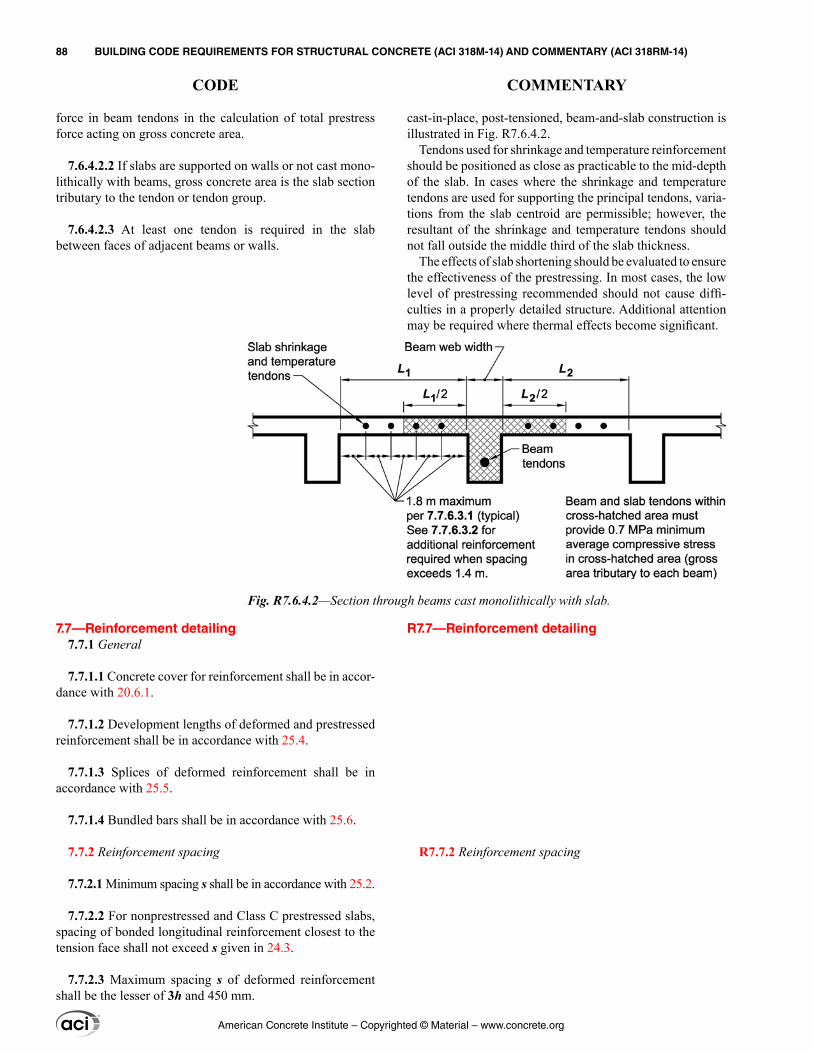
force in beam tendons in the calculation of total prestress force acting on gross concrete area.
7.6.4.2.2 If slabs are supported on walls or not cast mono-lithically with beams, gross concrete area is the slab section tributary to the tendon or tendon group.
7.6.4.2.3 At least one tendon is required in the slab between faces of adjacent beams or walls.
7.7—Reinforcement detailing 7.7.1 General
7.7.1.1 Concrete cover for reinforcement shall be in accor-dance with 20.6.1.
7.7.1.2 Development lengths of deformed and prestressed reinforcement shall be in accordance with 25.4.
7.7.1.3 Splices of deformed reinforcement shall be in accordance with 25.5.
7.7.1.4 Bundled bars shall be in accordance with 25.6.
7.7.2 Reinforcement spacing
7.7.2.1 Minimum spacing s shall be in accordance with 25.2.
7.7.2.2 For nonprestressed and Class C prestressed slabs, spacing of bonded longitudinal reinforcement closest to the tension face shall not exceed s given in 24.3.
7.7.2.3 Maximum spacing s of deformed reinforcement shall be the lesser of 3h and 450 mm.
cast-in-place, post-tensioned, beam-and-slab construction is illustrated in Fig. R7.6.4.2.
Tendons used for shrinkage and temperature reinforcement should be positioned as close as practicable to the mid-depth of the slab. In cases where the shrinkage and temperature tendons are used for supporting the principal tendons, varia-tions from the slab centroid are permissible; however, the resultant of the shrinkage and temperature tendons should not fall outside the middle third of the slab thickness.
The effects of slab shortening should be evaluated to ensure the effectiveness of the prestressing. In most cases, the low level of prestressing recommended should not cause diffi-culties in a properly detailed structure. Additional attention may be required where thermal effects become significant.
R7.7—Reinforcement detailing
R7.7.2 Reinforcement spacing
Fig. R7.6.4.2—Section through beams cast monolithically with slab.
American Concrete Institute – Copyrighted © Material – www.concrete.org
88 BUILDING CODE REQUIREMENTS FOR STRUCTURAL CONCRETE (ACI 318M-14) AND COMMENTARY (ACI 318RM-14)
CODE COMMENTARY
7.7.2.4 Spacing of reinforcement required by 7.5.2.3 shall not exceed the lesser of 5h and 450 mm.
7.7.3 Flexural reinforcement in nonprestressed slabs
7.7.3.1 Calculated tensile or compressive force in rein-forcement at each section of the slab shall be developed on each side of that section.
7.7.3.2 Critical locations for development of reinforce-ment are points of maximum stress and points along the span where bent or terminated tension reinforcement is no longer required to resist flexure.
7.7.3.3 Reinforcement shall extend beyond the point at which it is no longer required to resist flexure for a distance at least the greater of d and 12db, except at supports of simply-supported spans and at free ends of cantilevers.
7.7.3.4 Continuing flexural tension reinforcement shall have an embedment length at least ℓd beyond the point where bent or terminated tension reinforcement is no longer required to resist flexure.
7.7.3.5 Flexural tension reinforcement shall not be termi-nated in a tension zone unless (a), (b), or (c) is satisfied:
(a) Vu ≤ (2/3)ϕVn at the cutoff point.(b) For No. 36 bars and smaller, continuing reinforcement provides double the area required for flexure at the cutoff point and Vu ≤ (3/4)ϕVn.(c) Stirrup area in excess of that required for shear is provided along each terminated bar or wire over a distance 3/4d from the termination point. Excess stirrup area shall be not less than 0.41bws/fyt. Spacing s shall not exceed d/(8βb).
7.7.3.6 Adequate anchorage shall be provided for tension reinforcement where reinforcement stress is not directly proportional to moment, such as in sloped, stepped, or tapered slabs, or where tension reinforcement is not parallel to the compression face.
7.7.3.7 In slabs with spans not exceeding 3 m, welded wire reinforcement, with wire size not exceeding MW30 or MD30, shall be permitted to be curved from a point near the top of slab over the support to a point near the bottom of slab at midspan, provided such reinforcement is continuous over, or developed at, the support.
7.7.3.8 Termination of reinforcement
7.7.3.8.1 At simple supports, at least one-third of the maximum positive moment reinforcement shall extend along the slab bottom into the support, except for precast
R7.7.2.4 The spacing limitations for slab reinforcement are based on flange thickness, which for tapered flanges can be taken as the average thickness.
R7.7.3 Flexural reinforcement in nonprestressed slabs—Requirements for development of reinforcement in one-way slabs are similar to those for beams. Refer to R9.7.3 for addi-tional information.
R7.7.3.8 Termination of reinforcement—Requirements for termination of reinforcement in one-way slabs are similar to those for beams. Refer to R9.7.3.8 for additional information.
American Concrete Institute – Copyrighted © Material – www.concrete.org
CHAPTER 7—ONE-WAY SLABS 89
CODE COMMENTARY
7
slabs where such reinforcement shall extend at least to the center of the bearing length.
7.7.3.8.2 At other supports, at least one-fourth of the maximum positive moment reinforcement shall extend along the slab bottom into the support at least 150 mm.
7.7.3.8.3 At simple supports and points of inflection, db for positive moment tension reinforcement shall be limited such that ℓd for that reinforcement satisfies (a) or (b). If rein-forcement terminates beyond the centerline of supports by a standard hook or a mechanical anchorage at least equivalent to a standard hook, (a) or (b) need not be satisfied.
(a) ℓd ≤ (1.3Mn/Vu + ℓa) if end of reinforcement is confined by a compressive reaction(b) ℓd ≤ (Mn/Vu + ℓa) if end of reinforcement is not confined by a compressive reaction
Mn is calculated assuming all reinforcement at the section is stressed to fy and Vu is calculated at the section. At a support, ℓa is the embedment length beyond the center of the support. At a point of inflection, ℓa is the embedment length beyond the point of inflection, limited to the greater of d and 12db.
7.7.3.8.4 At least one-third of the negative moment rein-forcement at a support shall have an embedment length beyond the point of inflection at least the greatest of d, 12db, and ℓn/16.
7.7.4 Flexural reinforcement in prestressed slabs
7.7.4.1 External tendons shall be attached to the member in a manner that maintains the specified eccentricity between the tendons and the concrete centroid through the full range of anticipated member deflections.
7.7.4.2 If nonprestressed reinforcement is required to satisfy flexural strength, the detailing requirements of 7.7.3 shall be satisfied.
7.7.4.3 Termination of prestressed reinforcement
7.7.4.3.1 Post-tensioned anchorage zones shall be designed and detailed in accordance with 25.9.
7.7.4.3.2 Post-tensioning anchorages and couplers shall be designed and detailed in accordance with 25.8.
7.7.4.4 Termination of deformed reinforcement in slabs with unbonded tendons
7.7.4.4.1 Length of deformed reinforcement required by 7.6.2.3 shall be in accordance with (a) and (b):
R7.7.4 Flexural reinforcement in prestressed slabs
R7.7.4.4 Termination of deformed reinforcement in slabs with unbonded tendons—Requirements for termination of deformed reinforcement in one-way slabs with unbonded tendons are the same as those for beams. Refer to R9.7.4.4 for additional information.
American Concrete Institute – Copyrighted © Material – www.concrete.org
90 BUILDING CODE REQUIREMENTS FOR STRUCTURAL CONCRETE (ACI 318M-14) AND COMMENTARY (ACI 318RM-14)
CODE COMMENTARY
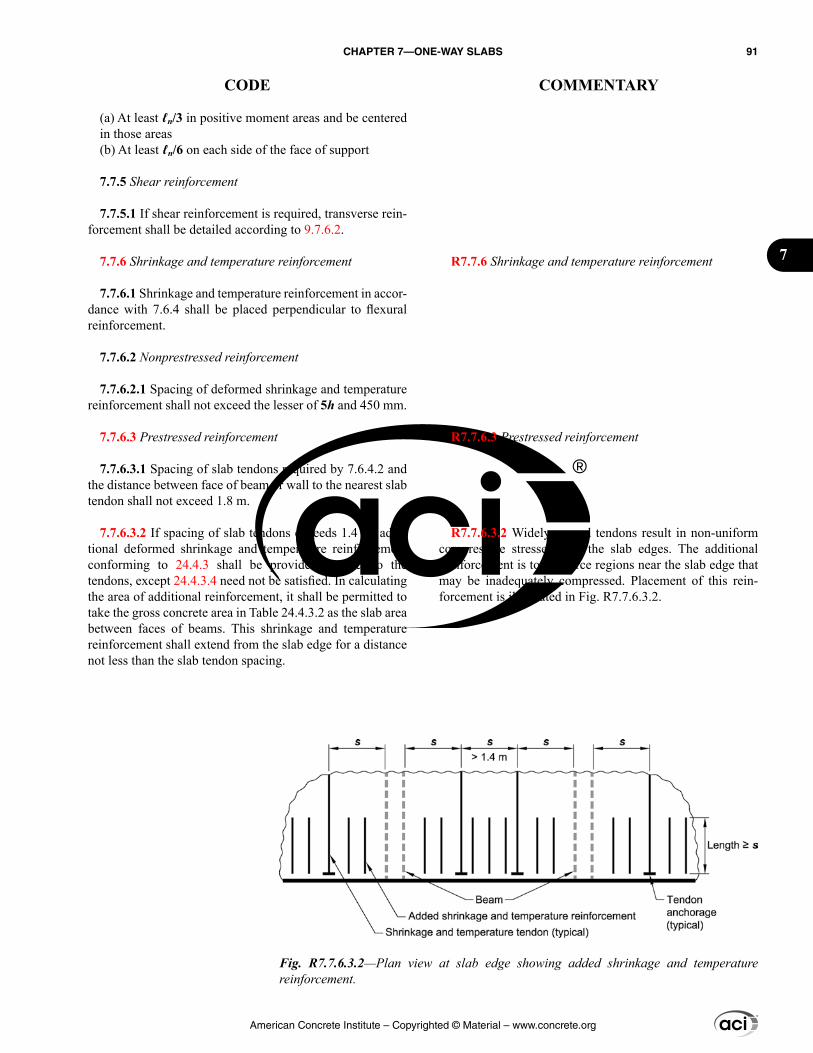
(a) At least ℓn/3 in positive moment areas and be centered in those areas(b) At least ℓn/6 on each side of the face of support
7.7.5 Shear reinforcement
7.7.5.1 If shear reinforcement is required, transverse rein-forcement shall be detailed according to 9.7.6.2.
7.7.6 Shrinkage and temperature reinforcement
7.7.6.1 Shrinkage and temperature reinforcement in accor-dance with 7.6.4 shall be placed perpendicular to flexural reinforcement.
7.7.6.2 Nonprestressed reinforcement
7.7.6.2.1 Spacing of deformed shrinkage and temperature reinforcement shall not exceed the lesser of 5h and 450 mm.
7.7.6.3 Prestressed reinforcement
7.7.6.3.1 Spacing of slab tendons required by 7.6.4.2 and the distance between face of beam or wall to the nearest slab tendon shall not exceed 1.8 m.
7.7.6.3.2 If spacing of slab tendons exceeds 1.4 m, addi-tional deformed shrinkage and temperature reinforcement conforming to 24.4.3 shall be provided parallel to the tendons, except 24.4.3.4 need not be satisfied. In calculating the area of additional reinforcement, it shall be permitted to take the gross concrete area in Table 24.4.3.2 as the slab area between faces of beams. This shrinkage and temperature reinforcement shall extend from the slab edge for a distance not less than the slab tendon spacing.
R7.7.6 Shrinkage and temperature reinforcement
R7.7.6.3 Prestressed reinforcement
R7.7.6.3.2 Widely spaced tendons result in non-uniform compressive stresses near the slab edges. The additional reinforcement is to reinforce regions near the slab edge that may be inadequately compressed. Placement of this rein-forcement is illustrated in Fig. R7.7.6.3.2.
Fig. R7.7.6.3.2—Plan view at slab edge showing added shrinkage and temperature reinforcement.
American Concrete Institute – Copyrighted © Material – www.concrete.org
CHAPTER 7—ONE-WAY SLABS 91
CODE COMMENTARY
7

American Concrete Institute – Copyrighted © Material – www.concrete.org
92 BUILDING CODE REQUIREMENTS FOR STRUCTURAL CONCRETE (ACI 318M-14) AND COMMENTARY (ACI 318RM-14)
Notes
CHAPTER 8—TWO-WAY SLABS
8.1—Scope 8.1.1 This chapter shall apply to the design of nonpre-
stressed and prestressed slabs reinforced for flexure in two directions, with or without beams between supports, including (a) through (d):
(a) Solid slabs(b) Slabs cast on stay-in-place, noncomposite steel deck(c) Composite slabs of concrete elements constructed in separate placements but connected so that all elements resist loads as a unit(d) Two-way joist systems in accordance with 8.8
8.2—General 8.2.1 A slab system shall be permitted to be designed
by any procedure satisfying equilibrium and geometric compatibility, provided that design strength at every section is at least equal to required strength, and all serviceability requirements are satisfied. The direct design method of 8.10 or the equivalent frame method of 8.11 is permitted for design where applicable.
R8—TWO-WAY SLABS
R8.1—Scope The design methods given in this chapter are based on
analysis of the results of an extensive series of tests (Burns and Hemakom 1977; Gamble et al. 1969; Gerber and Burns 1971; Guralnick and LaFraugh 1963; Hatcher et al. 1965, 1969; Hawkins 1981; Jirsa et al. 1966; PTI DC20.8; Smith and Burns 1974; Scordelis et al. 1959; Vanderbilt et al. 1969; Xanthakis and Sozen 1963) and the well-established performance records of various slab systems. The funda-mental design principles are applicable to all planar struc-tural systems subjected to transverse loads. Several specific design rules, as well as historical precedents, limit the types of structures to which this chapter applies. General slab systems that may be designed according to this chapter include flat slabs, flat plates, two-way slabs, and waffle slabs. Slabs with paneled ceilings are two-way, wide-band, beam systems.
Slabs-on-ground that do not transmit vertical loads from other parts of the structure to the soil are excluded.
For slabs with beams, the explicit design procedures of this chapter apply only when the beams are located at the edges of the panel and when the beams are supported by columns or other essentially nondeflecting supports at the corners of the panel. Two-way slabs with beams in one direction, with both slab and beams supported by girders in the other direction, may be designed under the general requirements of this chapter. Such designs should be based upon analysis compatible with the deflected position of the supporting beams and girders.
For slabs supported on walls, the explicit design proce-dures in this chapter treat the wall as a beam of infinite stiff-ness; therefore, each wall should support the entire length of an edge of the panel (refer to 8.4.1.7). Walls of width less than a full panel length can be treated as columns.
R8.2—General R8.2.1 This section permits a design to be based directly
on fundamental principles of structural mechanics, provided it can be demonstrated explicitly that all strength and serviceability criteria are satisfied. The design of the slab may be achieved through the combined use of classic solu-tions based on a linearly elastic continuum, numerical solu-tions based on discrete elements, or yield-line analyses, including, in all cases, evaluation of the stress conditions around the supports in relation to shear and torsion as well as flexure. The design of a slab system involves more than its analysis; any deviations in physical dimensions of the slab from common practice should be justified on the basis of knowledge of the expected loads and the reliability of the calculated stresses and deformations of the structure.
For gravity load analysis of two-way slab systems, two analysis methods are given in 8.10 and 8.11. The specific provisions of both design methods are limited in applica-tion to orthogonal frames subject to gravity loads only. Both
American Concrete Institute – Copyrighted © Material – www.concrete.org
CHAPTER 8—TWO-WAY SLABS 93
CODE COMMENTARY
8
methods apply to two-way slabs with beams as well as to flat slabs and flat plates. In both methods, the distribution of moments to the critical sections of the slab reflects the effects of reduced stiffness of elements due to cracking and support geometry.
R8.2.4 and R8.2.5 Drop panel dimensions specified in 8.2.4 are necessary when reducing the amount of nega-tive moment reinforcement following 8.5.2.2 or to satisfy minimum slab thicknesses permitted in 8.3.1.1. If the dimen-sions are less than specified in 8.2.4, the projection may be used as a shear cap to increase the shear strength of the slab. For slabs with changes in thickness, it is necessary to check the shear strength at several sections (Refer to 22.6.4.1(b)).
R8.2.7 Connections to other members—Safety of a slab system requires consideration of the transmission of load from the slab to the columns by flexure, torsion, and shear.
R8.3—Design limits R8.3.1 Minimum slab thickness—The minimum slab
thicknesses in 8.3.1.1 and 8.3.1.2 are independent of loading and concrete modulus of elasticity, both of which have significant effects on deflections. These minimum thick-nesses are not applicable to slabs with unusually heavy superimposed sustained loads or for concrete with modulus of elasticity significantly lower than that of ordinary normal-
8.2.2 The effects of concentrated loads and openings shall be considered in design.
8.2.3 Slabs prestressed with an average effective compres-sive stress less than 0.9 MPa shall be designed as nonpre-stressed slabs.
8.2.4 A drop panel in a nonprestressed slab, where used to reduce the minimum required thickness in accordance with 8.3.1.1 or the quantity of deformed negative moment reinforcement at a support in accordance with 8.5.2.2, shall satisfy (a) and (b):
(a) The drop panel shall project below the slab at least one-fourth of the adjacent slab thickness.(b) The drop panel shall extend in each direction from the centerline of support a distance not less than one-sixth the span length measured from center-to-center of supports in that direction.
8.2.5 A shear cap, where used to increase the critical section for shear at a slab-column joint, shall project below the slab soffit and extend horizontally from the face of the column a distance at least equal to the thickness of the projection below the slab soffit.
8.2.6 Materials
8.2.6.1 Design properties for concrete shall be selected to be in accordance with Chapter 19.
8.2.6.2 Design properties for steel reinforcement shall be selected to be in accordance with Chapter 20.
8.2.6.3 Materials, design, and detailing requirements for embedments in concrete shall be in accordance with 20.7.
8.2.7 Connections to other members
8.2.7.1 Beam-column and slab-column joints shall satisfy Chapter 15.
8.3—Design limits 8.3.1 Minimum slab thickness
American Concrete Institute – Copyrighted © Material – www.concrete.org
94 BUILDING CODE REQUIREMENTS FOR STRUCTURAL CONCRETE (ACI 318M-14) AND COMMENTARY (ACI 318RM-14)
CODE COMMENTARY
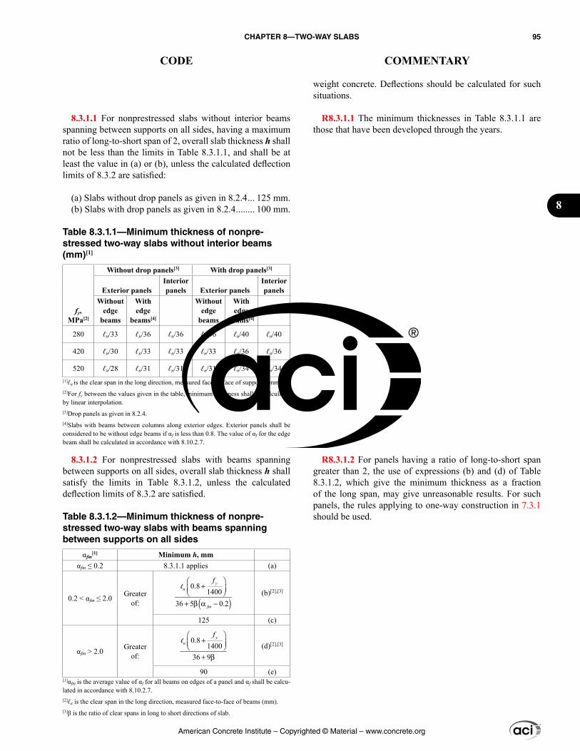
weight concrete. Deflections should be calculated for such situations.
R8.3.1.1 The minimum thicknesses in Table 8.3.1.1 are those that have been developed through the years.
R8.3.1.2 For panels having a ratio of long-to-short span greater than 2, the use of expressions (b) and (d) of Table 8.3.1.2, which give the minimum thickness as a fraction of the long span, may give unreasonable results. For such panels, the rules applying to one-way construction in 7.3.1 should be used.
8.3.1.1 For nonprestressed slabs without interior beams spanning between supports on all sides, having a maximum ratio of long-to-short span of 2, overall slab thickness h shall not be less than the limits in Table 8.3.1.1, and shall be at least the value in (a) or (b), unless the calculated deflection limits of 8.3.2 are satisfied:
(a) Slabs without drop panels as given in 8.2.4 ... 125 mm.(b) Slabs with drop panels as given in 8.2.4 ........ 100 mm.
Table 8.3.1.1—Minimum thickness of nonpre-stressed two-way slabs without interior beams (mm)[1]
fy, MPa[2]
Without drop panels[3] With drop panels[3]
Exterior panelsInterior panels Exterior panels
Interior panels
Without edge
beams
With edge
beams[4]
Without edge
beams
With edge
beams[4]
280 ℓn/33 ℓn/36 ℓn/36 ℓn/36 ℓn/40 ℓn/40
420 ℓn/30 ℓn/33 ℓn/33 ℓn/33 ℓn/36 ℓn/36
520 ℓn/28 ℓn/31 ℓn/31 ℓn/31 ℓn/34 ℓn/34[1]ℓn is the clear span in the long direction, measured face-to-face of supports (mm).[2]For fy between the values given in the table, minimum thickness shall be calculated by linear interpolation.[3]Drop panels as given in 8.2.4.[4]Slabs with beams between columns along exterior edges. Exterior panels shall be considered to be without edge beams if αf is less than 0.8. The value of αf for the edge beam shall be calculated in accordance with 8.10.2.7.
8.3.1.2 For nonprestressed slabs with beams spanning between supports on all sides, overall slab thickness h shall satisfy the limits in Table 8.3.1.2, unless the calculated deflection limits of 8.3.2 are satisfied.
Table 8.3.1.2—Minimum thickness of nonpre-stressed two-way slabs with beams spanning between supports on all sides
αfm[1] Minimum h, mm
αfm ≤ 0.2 8.3.1.1 applies (a)
0.2 < αfm ≤ 2.0 Greater of: ( )
0.81400
36 5 0.2
+
+ β α −
yn
fm
fl
(b)[2],[3]
125 (c)
αfm > 2.0 Greater of:
0.81400
36 9
+ + β
yn
fl
(d)[2],[3]
90 (e)[1]αfm is the average value of αf for all beams on edges of a panel and αf shall be calcu-lated in accordance with 8.10.2.7.[2]ℓn is the clear span in the long direction, measured face-to-face of beams (mm).[3]β is the ratio of clear spans in long to short directions of slab.
American Concrete Institute – Copyrighted © Material – www.concrete.org
CHAPTER 8—TWO-WAY SLABS 95
CODE COMMENTARY
8
R8.3.1.3 The Code does not specify an additional thick-ness for wearing surfaces subjected to unusual conditions of wear. The need for added thickness for unusual wear is left to the discretion of the licensed design professional.
A concrete floor finish may be considered for strength purposes only if it is cast monolithically with the slab. A separate concrete finish is permitted to be included in the structural thickness if composite action is provided in accor-dance with 16.4.
R8.3.2 Calculated deflection limits
R8.3.2.1 For prestressed flat slabs continuous over two or more spans in each direction, the span-thickness ratio generally should not exceed 42 for floors and 48 for roofs; these limits may be increased to 48 and 52, respectively, if calculations verify that both short- and long-term deflec-tion, camber, and vibration frequency and amplitude are not objectionable.
Short- and long-term deflection and camber should be calculated and checked against serviceability requirements of the structure.
R8.3.2.2 If any portion of a composite member is prestressed, or if the member is prestressed after the components have been cast, the provisions of 8.3.2.1 apply and deflections are to be calculated. For nonprestressed composite members, deflections need to be calculated and compared with the limiting values in Table 24.2.2, only when the thickness of the member or the precast part of the member is less than the minimum thickness given in Table 8.3.1.1. In unshored construction, the thickness of concern depends on whether the deflection before or after the attain-ment of effective composite action is being considered.
R8.3.3 Reinforcement strain limit in nonprestressed slabs
R8.3.3.1 The effect of this limitation is to restrict the rein-forcement ratio in nonprestressed slabs to mitigate brittle flexural behavior in case of an overload. This limitation does not apply to prestressed slabs.
8.3.1.2.1 At discontinuous edges of slabs conforming to 8.3.1.2, an edge beam with αf ≥ 0.80 shall be provided, or the minimum thickness required by (b) or (d) of Table 8.3.1.2 shall be increased by at least 10 percent in the panel with a discontinuous edge.
8.3.1.3 The thickness of a concrete floor finish shall be permitted to be included in h if it is placed monolithically with the floor slab, or if the floor finish is designed to be composite with the floor slab in accordance with 16.4.
8.3.1.4 If single- or multiple-leg stirrups are used as shear reinforcement, the slab thickness shall be sufficient to satisfy the requirements for d in 22.6.7.1.
8.3.2 Calculated deflection limits
8.3.2.1 Immediate and time-dependent deflections shall be calculated in accordance with 24.2 and shall not exceed the limits in 24.2.2 for two-way slabs given in (a) through (c):
(a) Nonprestressed slabs not satisfying 8.3.1(b) Nonprestressed slabs without interior beams spanning between the supports on all sides and having a ratio of long-to-short span exceeding 2.0(c) Prestressed slabs
8.3.2.2 For nonprestressed composite concrete slabs satisfying 8.3.1.1 or 8.3.1.2, deflections occurring after the member becomes composite need not be calculated. Deflec-tions occurring before the member becomes composite shall be investigated, unless the precomposite thickness also satis-fies 8.3.1.1 or 8.3.1.2.
8.3.3 Reinforcement strain limit in nonprestressed slabs
8.3.3.1 For nonprestressed slabs, εt shall be at least 0.004.
8.3.4 Stress limits in prestressed slabs
8.3.4.1 Prestressed slabs shall be designed as Class U with ft ≤ 0.50 ′fc . Other stresses in prestressed slabs immedi-
American Concrete Institute – Copyrighted © Material – www.concrete.org
96 BUILDING CODE REQUIREMENTS FOR STRUCTURAL CONCRETE (ACI 318M-14) AND COMMENTARY (ACI 318RM-14)
CODE COMMENTARY
R8.4—Required strength R8.4.1 General
R8.4.1.2 Use of the equivalent frame method of analysis (refer to 8.11) or numerical analysis procedures is required for determination of both service and factored moments and shears for prestressed slab systems. The equivalent frame method of analysis has been shown by tests of large structural models to satisfactorily predict factored moments and shears in prestressed slab systems (Smith and Burns 1974; Burns and Hemakom 1977; Hawkins 1981; PTI DC20.8; Gerber and Burns 1971; Scordelis et al. 1959). The referenced research also shows that analysis using prismatic sections or other approximations of stiffness may provide erroneous and unsafe results. Section 8.11.6.5 is excluded from appli-cation to prestressed slab systems. Moment redistribution for prestressed slabs, however, is permitted in accordance with 6.6.5. Section 8.11.6.6 does not apply to prestressed slab systems because the distribution of moments between column strips and middle strips required by 8.11.6.6 is based on tests for nonprestressed concrete slabs. Simplified methods of analysis using average coefficients do not apply to prestressed concrete slab systems. PTI DC20.8 provides guidance for prestressed concrete slab systems.
R8.4.1.7 A panel includes all flexural elements between column centerlines. Thus, the column strip includes the beam, if any.
ately after transfer and at service loads shall not exceed the permissible stresses in 24.5.3 and 24.5.4.
8.4—Required strength 8.4.1 General
8.4.1.1 Required strength shall be calculated in accor-dance with the factored load combinations in Chapter 5.
8.4.1.2 Required strength shall be calculated in accor-dance with the analysis procedures given in Chapter 6. Alternatively, the provisions of 8.10 for the direct design method shall be permitted for the analysis of nonprestressed slabs and the provisions of 8.11 for the equivalent frame method shall be permitted for the analysis of nonprestressed and prestressed slabs, except 8.11.6.5 and 8.11.6.6 shall not apply to prestressed slabs.
8.4.1.3 For prestressed slabs, effects of reactions induced by prestressing shall be considered in accordance with 5.3.11.
8.4.1.4 For a slab system supported by columns or walls, dimensions c1, c2, and ℓn shall be based on an effective support area. The effective support area is the intersection of the bottom surface of the slab, or drop panel or shear cap if present, with the largest right circular cone, right pyramid, or tapered wedge whose surfaces are located within the column and the capital or bracket and are oriented no greater than 45 degrees to the axis of the column.
8.4.1.5 A column strip is a design strip with a width on each side of a column centerline equal to the lesser of 0.25ℓ2 and 0.25ℓ1. A column strip shall include beams within the strip, if present.
8.4.1.6 A middle strip is a design strip bounded by two column strips.
8.4.1.7 A panel is bounded by column, beam, or wall centerlines on all sides.
American Concrete Institute – Copyrighted © Material – www.concrete.org
CHAPTER 8—TWO-WAY SLABS 97
CODE COMMENTARY
8
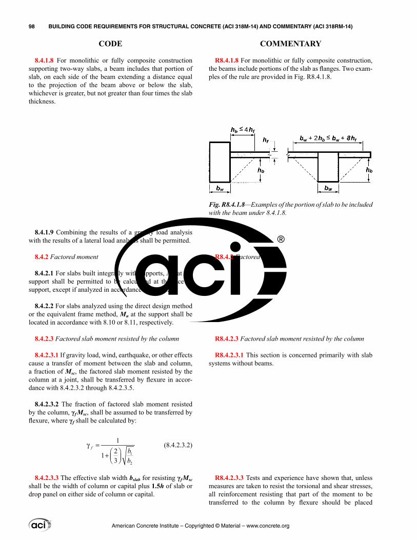
8.4.1.8 For monolithic or fully composite construction supporting two-way slabs, a beam includes that portion of slab, on each side of the beam extending a distance equal to the projection of the beam above or below the slab, whichever is greater, but not greater than four times the slab thickness.
8.4.1.9 Combining the results of a gravity load analysis with the results of a lateral load analysis shall be permitted.
8.4.2 Factored moment
8.4.2.1 For slabs built integrally with supports, Mu at the support shall be permitted to be calculated at the face of support, except if analyzed in accordance with 8.4.2.2.
8.4.2.2 For slabs analyzed using the direct design method or the equivalent frame method, Mu at the support shall be located in accordance with 8.10 or 8.11, respectively.
8.4.2.3 Factored slab moment resisted by the column
8.4.2.3.1 If gravity load, wind, earthquake, or other effects cause a transfer of moment between the slab and column, a fraction of Msc, the factored slab moment resisted by the column at a joint, shall be transferred by flexure in accor-dance with 8.4.2.3.2 through 8.4.2.3.5.
8.4.2.3.2 The fraction of factored slab moment resisted by the column, γf Msc, shall be assumed to be transferred by flexure, where γf shall be calculated by:
1
2
1213
f bb
γ = +
(8.4.2.3.2)
8.4.2.3.3 The effective slab width bslab for resisting γfMsc shall be the width of column or capital plus 1.5h of slab or drop panel on either side of column or capital.
R8.4.1.8 For monolithic or fully composite construction, the beams include portions of the slab as flanges. Two exam-ples of the rule are provided in Fig. R8.4.1.8.
R8.4.2 Factored moment
R8.4.2.3 Factored slab moment resisted by the column
R8.4.2.3.1 This section is concerned primarily with slab systems without beams.
R8.4.2.3.3 Tests and experience have shown that, unless measures are taken to resist the torsional and shear stresses, all reinforcement resisting that part of the moment to be transferred to the column by flexure should be placed
Fig. R8.4.1.8—Examples of the portion of slab to be included with the beam under 8.4.1.8.
American Concrete Institute – Copyrighted © Material – www.concrete.org
98 BUILDING CODE REQUIREMENTS FOR STRUCTURAL CONCRETE (ACI 318M-14) AND COMMENTARY (ACI 318RM-14)
CODE COMMENTARY
8.4.2.3.4 For nonprestressed slabs, where the limitations on vug and εt in Table 8.4.2.3.4 are satisfied, γf shall be permitted to be increased to the maximum modified values provided in Table 8.4.2.3.4, where vc is calculated in accor-dance with 22.6.5, and vug is the factored shear stress on the slab critical section for two-way action due to gravity loads without moment transfer.
Table 8.4.2.3.4—Maximum modified values of γf for nonprestressed two-way slabs
Column location
Span direction vug
εt (within
bslab) Maximum modified γf
Corner column
Either direction ≤0.5ϕvc ≥0.004 1.0
Edge column
Perpen-dicular to the edge
≤0.75ϕvc ≥0.004 1.0
Parallel to the edge ≤0.4ϕvc ≥0.010 1
2
1.25 1.0213
bb
≤ +
Interior column
Either direction ≤0.4ϕvc ≥0.010 1
2
1.25 1.0213
bb
≤ +
8.4.2.3.5 Concentration of reinforcement over the column by closer spacing or additional reinforcement shall be used to resist moment on the effective slab width defined in 8.4.2.3.2 and 8.4.2.3.3.
8.4.2.3.6 The fraction of Msc not calculated to be resisted by flexure shall be assumed to be resisted by eccentricity of shear in accordance with 8.4.4.2.
8.4.3 Factored one-way shear
8.4.3.1 For slabs built integrally with supports, Vu at the support shall be permitted to be calculated at the face of support.
between lines that are one and one-half the slab or drop panel thickness, 1.5h, on each side of the column.
R8.4.2.3.4 Tests indicate that some flexibility in distri-bution of Msc transferred by shear and flexure at both exte-rior and interior columns is possible. Interior, exterior, and corner columns refer to slab-column connections for which the critical perimeter for rectangular columns has four, three, or two sides, respectively.
At exterior columns, for Msc resisted about an axis parallel to the edge, the portion of moment transferred by eccen-tricity of shear γvMsc may be reduced, provided that the factored shear at the column (excluding the shear produced by moment transfer) does not exceed 75 percent of the shear strength ϕvc as defined in 22.6.5.1 for edge columns, or 50 percent for corner columns. Tests (Moehle 1988; ACI 352.1R) indicate that there is no significant interaction between shear and Msc at the exterior column in such cases. Note that as γvMsc is decreased, γfMsc is increased.
Evaluation of tests of interior columns indicates that some flexibility in distributing Msc transferred by shear and flexure is possible, but with more severe limitations than for exterior columns. For interior columns, Msc transferred by flexure is permitted to be increased up to 25 percent, provided that the factored shear (excluding the shear caused by the moment transfer) at the interior columns does not exceed 40 percent of the shear strength ϕvc as defined in 22.6.5.1.
If the factored shear for a slab-column connection is large, the slab-column joint cannot always develop all of the rein-forcement provided in the effective width. The modifications for interior slab-column connections in this provision are permitted only where the reinforcement required to develop γfMsc within the effective width has a net tensile strain εt not less than 0.010. The use of Eq. (8.4.2.3.2) without the modification permitted in this provision will generally indi-cate overstress conditions on the joint. This provision is intended to improve ductile behavior of the slab-column joint. If reversal of moments occurs at opposite faces of an interior column, both top and bottom reinforcement should be concentrated within the effective width. A ratio of top-to-bottom reinforcement of approximately 2 has been observed to be appropriate.
American Concrete Institute – Copyrighted © Material – www.concrete.org
CHAPTER 8—TWO-WAY SLABS 99
CODE COMMENTARY
8
8.4.3.2 Sections between the face of support and a critical section located d from the face of support for nonprestressed slabs and h/2 from the face of support for prestressed slabs shall be permitted to be designed for Vu at that critical section if (a) through (c) are satisfied:
(a) Support reaction, in direction of applied shear, intro-duces compression into the end regions of the slab.(b) Loads are applied at or near the top surface of the slab.(c) No concentrated load occurs between the face of support and critical section.
8.4.4 Factored two-way shear
8.4.4.1 Critical section
8.4.4.1.1 Slabs shall be evaluated for two-way shear in the vicinity of columns, concentrated loads, and reaction areas at critical sections in accordance with 22.6.4.
8.4.4.1.2 Slabs reinforced with stirrups or headed shear stud reinforcement shall be evaluated for two-way shear at critical sections in accordance with 22.6.4.2.
8.4.4.1.3 Slabs reinforced with shearheads shall be eval-uated for two-way shear at critical sections in accordance with 22.6.9.8.
8.4.4.2 Factored two-way shear stress due to shear and factored slab moment resisted by the column
8.4.4.2.1 For two-way shear with factored slab moment resisted by the column, factored shear stress vu shall be calculated at critical sections in accordance with 8.4.4.1. Factored shear stress vu corresponds to a combination of vug and the shear stress produced by γvMsc, where γv is given in 8.4.4.2.2 and Msc is given in 8.4.2.3.1.
8.4.4.2.2 The fraction of Msc transferred by eccentricity of shear, γvMsc, shall be applied at the centroid of the critical section in accordance with 8.4.4.1, where:
γv = 1 – γf (8.4.4.2.2)
8.4.4.2.3 The factored shear stress resulting from γvMsc shall be assumed to vary linearly about the centroid of the critical section in accordance with 8.4.4.1.
R8.4.4 Factored two-way shear—The calculated shear stresses in the slab around the column are required to conform to the requirements of 22.6.
R8.4.4.2 Factored two-way shear stress due to shear and factored slab moment resisted by the column
R8.4.4.2.2 Hanson and Hanson (1968) found that where moment is transferred between a column and a slab, 60 percent of the moment should be considered transferred by flexure across the perimeter of the critical section defined in 22.6.4.1, and 40 percent by eccentricity of the shear about the centroid of the critical section. For rectangular columns, the portion of the moment transferred by flexure increases as the width of the face of the critical section resisting the moment increases, as given by Eq. (8.4.2.3.2).
Most of the data in Hanson and Hanson (1968) were obtained from tests of square columns. Limited informa-tion is available for round columns; however, these can be approximated as square columns according to 8.10.1.3.
R8.4.4.2.3 The stress distribution is assumed as illus-trated in Fig. R8.4.4.2.3 for an interior or exterior column. The perimeter of the critical section, ABCD, is determined in accordance with 22.6.4.1. The factored shear stress vug
American Concrete Institute – Copyrighted © Material – www.concrete.org
100 BUILDING CODE REQUIREMENTS FOR STRUCTURAL CONCRETE (ACI 318M-14) AND COMMENTARY (ACI 318RM-14)
CODE COMMENTARY
and factored slab moment resisted by the column Msc are determined at the centroidal axis c-c of the critical section. The maximum factored shear stress may be calculated from:
,v sc AB
u AB ugc
M cv v
Jγ
= +
or
,v sc CD
u CD ugc
M cv v
Jγ
= −
where γv is given by Eq. (8.4.4.2.2).For an interior column, Jc may be calculated by:
Jc = property of assumed critical section analogous to polar moment of inertia
( ) ( ) ( )( )3 231 1 2 1
6 6 2d c d c d d d c d c d+ + + +
= + +
Similar equations may be developed for Jc for columns located at the edge or corner of a slab.
The fraction of Msc not transferred by eccentricity of the shear should be transferred by flexure in accordance with 8.4.2.3. A conservative method assigns the fraction trans-ferred by flexure over an effective slab width defined in 8.4.2.3.3. Often, column strip reinforcement is concentrated near the column to accommodate Msc. Available test data (Hanson and Hanson 1968) seem to indicate that this prac-tice does not increase shear strength but may be desirable to increase the stiffness of the slab-column junction.
Test data (Hawkins 1981) indicate that the moment transfer strength of a prestressed slab-to-column connection can be calculated using the procedures of 8.4.2.3 and 8.4.4.2.
Where shear reinforcement has been used, the critical section beyond the shear reinforcement generally has a polygonal shape (Fig. R8.7.6d and e). Equations for calcu-lating shear stresses on such sections are given in ACI 421.1R.
American Concrete Institute – Copyrighted © Material – www.concrete.org
CHAPTER 8—TWO-WAY SLABS 101
CODE COMMENTARY
8
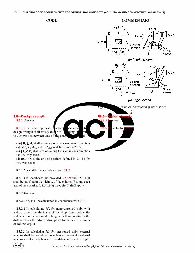
8.5—Design strength 8.5.1 General
8.5.1.1 For each applicable factored load combination, design strength shall satisfy ϕSn ≥ U, including (a) through (d). Interaction between load effects shall be considered.
(a) ϕMn ≥ Mu at all sections along the span in each direction(b) ϕMn ≥ γfMsc within bslab as defined in 8.4.2.3.3(c) ϕVn ≥ Vu at all sections along the span in each direction for one-way shear(d) ϕvn ≥ vu at the critical sections defined in 8.4.4.1 for two-way shear
8.5.1.2 ϕ shall be in accordance with 21.2.
8.5.1.3 If shearheads are provided, 22.6.9 and 8.5.1.1(a) shall be satisfied in the vicinity of the column. Beyond each arm of the shearhead, 8.5.1.1(a) through (d) shall apply.
8.5.2 Moment
8.5.2.1 Mn shall be calculated in accordance with 22.3.
8.5.2.2 In calculating Mn for nonprestressed slabs with a drop panel, the thickness of the drop panel below the slab shall not be assumed to be greater than one-fourth the distance from the edge of drop panel to the face of column or column capital.
8.5.2.3 In calculating Mn for prestressed slabs, external tendons shall be considered as unbonded unless the external tendons are effectively bonded to the slab along its entire length.
R8.5—Design strength R8.5.1 General
R8.5.1.1 Refer to R9.5.1.1.
Fig. R8.4.4.2.3—Assumed distribution of shear stress.
American Concrete Institute – Copyrighted © Material – www.concrete.org
102 BUILDING CODE REQUIREMENTS FOR STRUCTURAL CONCRETE (ACI 318M-14) AND COMMENTARY (ACI 318RM-14)
CODE COMMENTARY
R8.5.3 Shear
R8.5.3.1 Differentiation should be made between a long and narrow slab acting as a beam, and a slab subject to two-way action where failure may occur by punching along a truncated cone or pyramid around a concentrated load or reaction area.
R8.6—Reinforcement limits R8.6.1 Minimum flexural reinforcement in nonprestressed
slabs
R8.6.1.1 The required area of deformed or welded wire reinforcement used as minimum flexural reinforcement is the same as that required for shrinkage and temperature in 24.4.3.2. However, whereas shrinkage and temperature rein-forcement is permitted to be distributed between the two faces of the slab as deemed appropriate for specific condi-
8.5.3 Shear
8.5.3.1 Design shear strength of slabs in the vicinity of columns, concentrated loads, or reaction areas shall be the more severe of 8.5.3.1.1 and 8.5.3.1.2.
8.5.3.1.1 For one-way shear, where each critical section to be investigated extends in a plane across the entire slab width, Vn shall be calculated in accordance with 22.5.
8.5.3.1.2 For two-way shear, vn shall be calculated in accordance with 22.6.
8.5.3.2 For composite concrete slabs, horizontal shear strength Vnh shall be calculated in accordance with 16.4.
8.5.4 Openings in slab systems
8.5.4.1 Openings of any size shall be permitted in slab systems if shown by analysis that all strength and service-ability requirements, including the limits on deflections, are satisfied.
8.5.4.2 As an alternative to 8.5.4.1, openings shall be permitted in slab systems without beams in accordance with (a) through (d).
(a) Openings of any size shall be permitted in the area common to intersecting middle strips, but the total quan-tity of reinforcement in the panel shall be at least that required for the panel without the opening.(b) At two intersecting column strips, not more than one-eighth the width of column strip in either span shall be interrupted by openings. A quantity of reinforcement at least equal to that interrupted by an opening shall be added on the sides of the opening.(c) At the intersection of one column strip and one middle strip, not more than one-fourth of the reinforcement in either strip shall be interrupted by openings. A quantity of reinforcement at least equal to that interrupted by an opening shall be added on the sides of the opening.(d) If an opening is located within a column strip or closer than 10h from a concentrated load or reaction area, 22.6.4.3 for slabs without shearheads or 22.6.9.9 for slabs with shearheads shall be satisfied.
8.6—Reinforcement limits 8.6.1 Minimum flexural reinforcement in nonprestressed
slabs
8.6.1.1 A minimum area of flexural reinforcement, As,min, shall be provided near the tension face in the direction of the span under consideration in accordance with Table 8.6.1.1.
American Concrete Institute – Copyrighted © Material – www.concrete.org
CHAPTER 8—TWO-WAY SLABS 103
CODE COMMENTARY
8
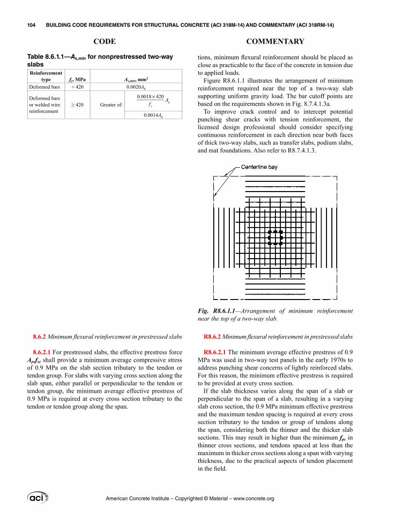
tions, minimum flexural reinforcement should be placed as close as practicable to the face of the concrete in tension due to applied loads.
Figure R8.6.1.1 illustrates the arrangement of minimum reinforcement required near the top of a two-way slab supporting uniform gravity load. The bar cutoff points are based on the requirements shown in Fig. 8.7.4.1.3a.
To improve crack control and to intercept potential punching shear cracks with tension reinforcement, the licensed design professional should consider specifying continuous reinforcement in each direction near both faces of thick two-way slabs, such as transfer slabs, podium slabs, and mat foundations. Also refer to R8.7.4.1.3.
R8.6.2 Minimum flexural reinforcement in prestressed slabs
R8.6.2.1 The minimum average effective prestress of 0.9 MPa was used in two-way test panels in the early 1970s to address punching shear concerns of lightly reinforced slabs. For this reason, the minimum effective prestress is required to be provided at every cross section.
If the slab thickness varies along the span of a slab or perpendicular to the span of a slab, resulting in a varying slab cross section, the 0.9 MPa minimum effective prestress and the maximum tendon spacing is required at every cross section tributary to the tendon or group of tendons along the span, considering both the thinner and the thicker slab sections. This may result in higher than the minimum fpc in thinner cross sections, and tendons spaced at less than the maximum in thicker cross sections along a span with varying thickness, due to the practical aspects of tendon placement in the field.
Table 8.6.1.1—As,min for nonprestressed two-way slabsReinforcement
type fy, MPa As,min, mm2
Deformed bars < 420 0.0020Ag
Deformed bars or welded wire reinforcement
≥ 420 Greater of:0.0018 420×
gy
Af
0.0014Ag
8.6.2 Minimum flexural reinforcement in prestressed slabs
8.6.2.1 For prestressed slabs, the effective prestress force Apsfse shall provide a minimum average compressive stress of 0.9 MPa on the slab section tributary to the tendon or tendon group. For slabs with varying cross section along the slab span, either parallel or perpendicular to the tendon or tendon group, the minimum average effective prestress of 0.9 MPa is required at every cross section tributary to the tendon or tendon group along the span.
Fig. R8.6.1.1—Arrangement of minimum reinforcement near the top of a two-way slab.
American Concrete Institute – Copyrighted © Material – www.concrete.org
104 BUILDING CODE REQUIREMENTS FOR STRUCTURAL CONCRETE (ACI 318M-14) AND COMMENTARY (ACI 318RM-14)
CODE COMMENTARY
R8.6.2.2 This provision is a precaution against abrupt flexural failure developing immediately after cracking. A flexural member designed according to Code provisions requires considerable additional load beyond cracking to reach its flexural strength. Thus, considerable deflection would warn that the member strength is approaching. If the flexural strength were reached shortly after cracking, the warning deflection would not occur. Transfer of force between the concrete and the prestressing steel, and abrupt flexural failure immediately after cracking, does not occur when the prestressing steel is unbonded (ACI 423.3R); therefore, this requirement does not apply to members with unbonded tendons.
R8.6.2.3 Some bonded reinforcement is required by the Code in prestressed slabs to limit crack width and spacing at service load when concrete tensile stresses exceed the modulus of rupture and, for slabs with unbonded tendons, to ensure flexural performance at nominal strength, rather than performance as a tied arch. Providing the minimum bonded reinforcement as stipulated in this provision helps to ensure adequate performance.
The minimum amount of bonded reinforcement in two-way flat slab systems is based on reports by Joint ACI-ASCE Committee 423 (1958) and ACI 423.3R. Limited research available for two-way flat slabs with drop panels (Odello and Mehta 1967) indicates that behavior of these particular systems is similar to the behavior of flat plates.
For usual loads and span lengths, flat plate tests summa-rized in Joint ACI-ASCE Committee 423 (1958) and expe-rience since the 1963 Code was adopted indicate satisfac-tory performance without bonded reinforcement in positive moment regions where ft ≤ 0.17 ′fc . In positive moment regions where 0.17 ′fc ≤ ft ≤ 0.50 ′fc , a minimum bonded reinforcement area proportioned to resist Nc according to Eq. (8.6.2.3(b)) is required. The tensile force Nc is calculated at service load on the basis of an uncracked, homogeneous section.
Research on unbonded post-tensioned two-way flat slab systems (Joint ACI-ASCE Committee 423 1958, 1974; ACI 423.3R; Odello and Mehta 1967) shows that bonded rein-forcement in negative moment regions, proportioned on the basis of 0.075 percent of the cross-sectional area of the slab-beam strip, provides sufficient ductility and reduces crack width and spacing. The same area of bonded reinforcement is required in slabs with either bonded or unbonded tendons. The minimum bonded reinforcement area required by Eq. (8.6.2.3(c)) is a minimum area independent of grade of rein-forcement or design yield strength. To account for different adjacent tributary spans, this equation is given on the basis of the equivalent frame as defined in 8.11.2 and pictured in Fig. R8.11.2. For rectangular slab panels, this equation is conser-vatively based on the greater of the cross-sectional areas of the two intersecting equivalent frame slab-beam strips at the column. This ensures that the minimum percentage of reinforcement recommended by research is provided in
8.6.2.2 For slabs with bonded prestressed reinforcement, total quantity of As and Aps shall be adequate to develop a factored load at least 1.2 times the cracking load calculated on the basis of fr defined in 19.2.3.
8.6.2.2.1 For slabs with both flexural and shear design strength at least twice the required strength, 8.6.2.2 need not be satisfied.
8.6.2.3 For prestressed slabs, a minimum area of bonded deformed longitudinal reinforcement, As,min, shall be provided in the precompressed tension zone in the direction of the span under consideration in accordance with Table 8.6.2.3.
Table 8.6.2.3—Minimum bonded deformed longi-tudinal reinforcement As,min in two-way slabs with bonded or unbonded tendons
RegionCalculated ft after all
losses, MPa As,min, mm2
Positive moment
0.17≤ ′t cf f Not required (a)
0.17 0.50< ≤′ ′c t cf f f0.5
c
y
Nf (b)[1],[2],[4]
Negative moment at columns
0.50≤ ′t cf f 0.00075Acf (c)[3],[4]
[1]The value of fy shall not exceed 420 MPa.[2]Nc is the resultant tensile force acting on the portion of the concrete cross section that is subjected to tensile stresses due to the combined effects of service loads and effective prestress.[3]Acf is the greater gross cross-sectional area of the slab-beam strips of the two orthog-onal equivalent frames intersecting at a column of a two-way slab.[4]For slabs with bonded tendons, it shall be permitted to reduce As,min by the area of the bonded prestressed reinforcement located within the area used to determine Nc for positive moment, or within the width of slab defined in 8.7.5.3(a) for negative moment.
American Concrete Institute – Copyrighted © Material – www.concrete.org
CHAPTER 8—TWO-WAY SLABS 105
CODE COMMENTARY
8
both directions. Concentration of this reinforcement in the top of the slab directly over and immediately adjacent to the column is important. Research also shows that where low tensile stresses occur at service loads, satisfactory behavior has been achieved at factored loads without bonded rein-forcement. However, the Code requires minimum bonded reinforcement regardless of service load stress levels to help ensure flexural continuity and ductility, and to limit crack widths and spacing due to overload, temperature, or shrinkage. Research on post-tensioned flat plate-to-column connections is reported in Smith and Burns (1974), Burns and Hemakom (1977), Hawkins (1981), PTI TAB.1, and Foutch et al. (1990).
Research has shown that unbonded post-tensioned members do not inherently provide large capacity for energy dissipation under severe earthquake loadings because the member response is primarily elastic. For this reason, unbonded post-tensioned structural members reinforced in accordance with the provisions of this section should be assumed to resist only vertical loads and to act as horizontal diaphragms between energy-dissipating elements under earthquake loadings of the magnitude defined in 18.2.1.
R8.7—Reinforcement detailing
R8.7.2 Flexural reinforcement spacing
R8.7.2.2 The requirement that the center-to-center spacing of the reinforcement be not more than two times the slab thickness applies only to the reinforcement in solid slabs, and not to reinforcement in joists or waffle slabs. This limi-tation is to ensure slab action, control cracking, and provide for the possibility of loads concentrated on small areas of the slab. Refer also to R24.3.
R8.7.2.3 This section provides specific guidance concerning tendon distribution that will permit the use of banded tendon distributions in one direction. This method of tendon distribu-tion has been shown to provide satisfactory performance by structural research (Burns and Hemakom 1977).
8.7—Reinforcement detailing 8.7.1 General
8.7.1.1 Concrete cover for reinforcement shall be in accor-dance with 20.6.1.
8.7.1.2 Development lengths of deformed and prestressed reinforcement shall be in accordance with 25.4.
8.7.1.3 Splice lengths of deformed reinforcement shall be in accordance with 25.5.
8.7.1.4 Bundled bars shall be detailed in accordance with 25.6.
8.7.2 Flexural reinforcement spacing
8.7.2.1 Minimum spacing s shall be in accordance with 25.2.
8.7.2.2 For nonprestressed solid slabs, maximum spacing s of deformed longitudinal reinforcement shall be the lesser of 2h and 450 mm at critical sections, and the lesser of 3h and 450 mm at other sections.
8.7.2.3 For prestressed slabs with uniformly distributed loads, maximum spacing s of tendons or groups of tendons in at least one direction shall be the lesser of 8h and 1.5 m.
American Concrete Institute – Copyrighted © Material – www.concrete.org
106 BUILDING CODE REQUIREMENTS FOR STRUCTURAL CONCRETE (ACI 318M-14) AND COMMENTARY (ACI 318RM-14)
CODE COMMENTARY
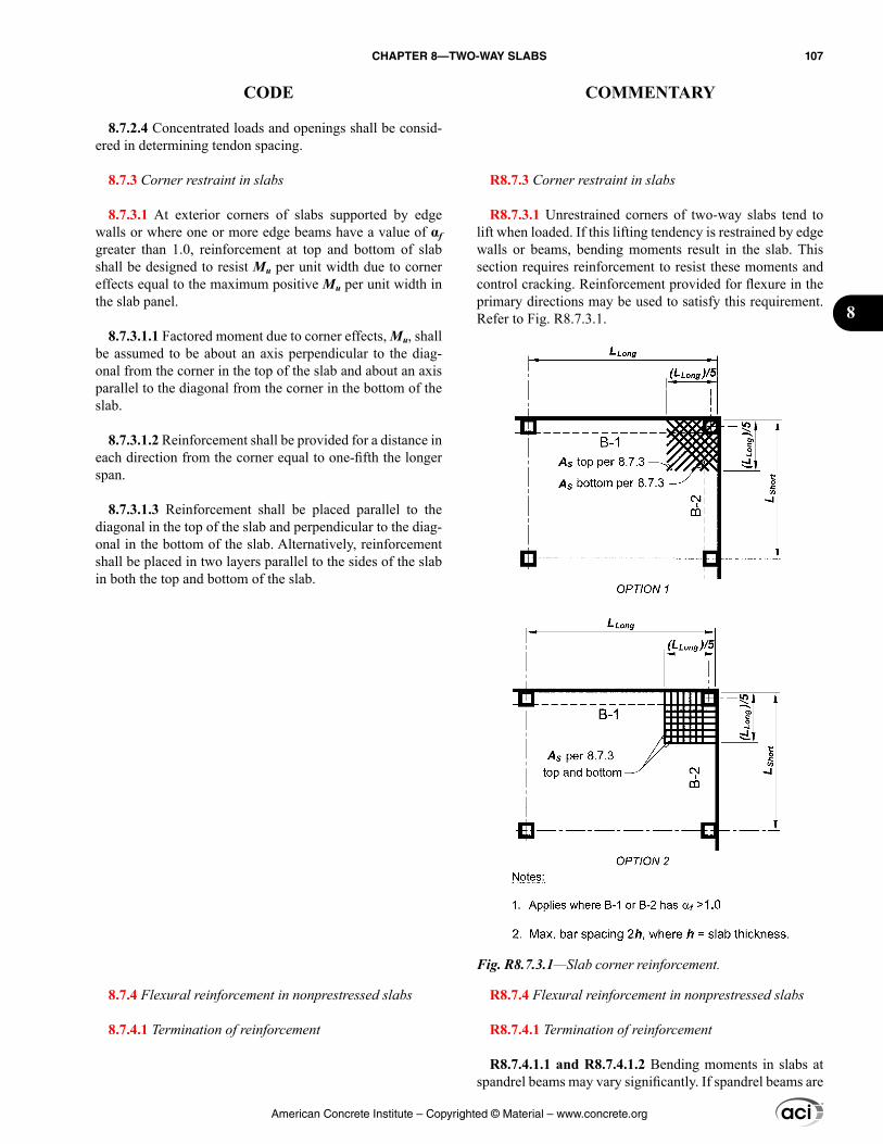
R8.7.3 Corner restraint in slabs
R8.7.3.1 Unrestrained corners of two-way slabs tend to lift when loaded. If this lifting tendency is restrained by edge walls or beams, bending moments result in the slab. This section requires reinforcement to resist these moments and control cracking. Reinforcement provided for flexure in the primary directions may be used to satisfy this requirement. Refer to Fig. R8.7.3.1.
R8.7.4 Flexural reinforcement in nonprestressed slabs
R8.7.4.1 Termination of reinforcement
R8.7.4.1.1 and R8.7.4.1.2 Bending moments in slabs at spandrel beams may vary significantly. If spandrel beams are
8.7.2.4 Concentrated loads and openings shall be consid-ered in determining tendon spacing.
8.7.3 Corner restraint in slabs
8.7.3.1 At exterior corners of slabs supported by edge walls or where one or more edge beams have a value of αf greater than 1.0, reinforcement at top and bottom of slab shall be designed to resist Mu per unit width due to corner effects equal to the maximum positive Mu per unit width in the slab panel.
8.7.3.1.1 Factored moment due to corner effects, Mu, shall be assumed to be about an axis perpendicular to the diag-onal from the corner in the top of the slab and about an axis parallel to the diagonal from the corner in the bottom of the slab.
8.7.3.1.2 Reinforcement shall be provided for a distance in each direction from the corner equal to one-fifth the longer span.
8.7.3.1.3 Reinforcement shall be placed parallel to the diagonal in the top of the slab and perpendicular to the diag-onal in the bottom of the slab. Alternatively, reinforcement shall be placed in two layers parallel to the sides of the slab in both the top and bottom of the slab.
8.7.4 Flexural reinforcement in nonprestressed slabs
8.7.4.1 Termination of reinforcement
Fig. R8.7.3.1—Slab corner reinforcement.
American Concrete Institute – Copyrighted © Material – www.concrete.org
CHAPTER 8—TWO-WAY SLABS 107
CODE COMMENTARY
8
built solidly into walls, the slab approaches complete fixity. Without an integral wall, the slab could approach being simply supported, depending on the torsional rigidity of the spandrel beam or slab edge. These requirements provide for unknown conditions that might normally occur in a structure.
R8.7.4.1.3 The minimum lengths and extensions of rein-forcement shown in Fig. 8.7.4.1.3a were developed for slabs of normal proportions supporting gravity loads. These minimum lengths and extensions may not be sufficient for thick two-way slabs such as transfer slabs, podium slabs, and mat foundations. As illustrated in Fig. R8.7.4.1.3b, punching shear cracks, which can develop at angles as low as about 20 degrees, may not be intercepted by the tension reinforcement, substantially reducing punching shear strength. Providing continuous reinforcement or extending the minimum lengths in Fig. 8.7.4.1.3a should be consid-ered for slabs with ℓn/h ratios less than about 15. Also, for moments resulting from combined lateral and gravity load-ings, the minimum lengths and extensions of bars in Fig. 8.7.4.1.3a may not be sufficient.
Bent bars are seldom used and are difficult to place prop-erly. Bent bars, however, are permitted provided they comply with 8.7.4.1.3(c). Further guidance on the use of bent bar systems can be found in 13.4.8 of the 1983 Code.
8.7.4.1.1 Where a slab is supported on spandrel beams, columns, or walls, anchorage of reinforcement perpendic-ular to a discontinuous edge shall satisfy (a) and (b):
(a) Positive moment reinforcement shall extend to the edge of slab and have embedment, straight or hooked, at least 150 mm into spandrel beams, columns, or walls(b) Negative moment reinforcement shall be bent, hooked, or otherwise anchored into spandrel beams, columns, or walls, and shall be developed at the face of support
8.7.4.1.2 Where a slab is not supported by a spandrel beam or wall at a discontinuous edge, or where a slab cantilevers beyond the support, anchorage of reinforcement shall be permitted within the slab.
8.7.4.1.3 For slabs without beams, reinforcement exten-sions shall be in accordance with (a) through (c):
(a) Reinforcement lengths shall be at least in accordance with Fig. 8.7.4.1.3a, and if slabs act as primary members resisting lateral loads, reinforcement lengths shall be at least those required by analysis.(b) If adjacent spans are unequal, extensions of nega-tive moment reinforcement beyond the face of support in accordance with Fig. 8.7.4.1.3a shall be based on the longer span.(c) Bent bars shall be permitted only where the depth-to-span ratio permits use of bends of 45 degrees or less.
American Concrete Institute – Copyrighted © Material – www.concrete.org
108 BUILDING CODE REQUIREMENTS FOR STRUCTURAL CONCRETE (ACI 318M-14) AND COMMENTARY (ACI 318RM-14)
CODE COMMENTARY
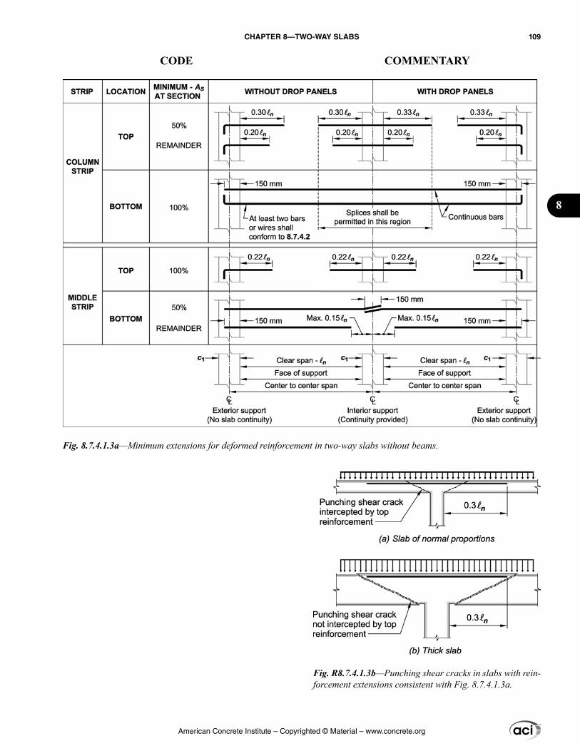
Fig. 8.7.4.1.3a—Minimum extensions for deformed reinforcement in two-way slabs without beams.
Fig. R8.7.4.1.3b—Punching shear cracks in slabs with rein-forcement extensions consistent with Fig. 8.7.4.1.3a.
American Concrete Institute – Copyrighted © Material – www.concrete.org
CHAPTER 8—TWO-WAY SLABS 109
CODE COMMENTARY
8
R8.7.4.2 Structural integrity
R8.7.4.2.1 and R8.7.4.2.2 The continuous column strip bottom reinforcement provides the slab some residual ability to span to the adjacent supports should a single support be damaged. The two continuous column strip bottom bars or wires through the column may be termed “integrity rein-forcement,” and are provided to give the slab some residual strength following a single punching shear failure at a single support (Mitchell and Cook 1984). Joint ACI-ASCE Committee 352 (ACI 352.1R) provides further guidance on the design of integrity reinforcement in slab-column connec-tions. Similar provisions for slabs with unbonded tendons are provided in 8.7.5.6.
R8.7.4.2.3 This provision requires the same integrity rein-forcement as for other two-way slabs without beams in case of a punching shear failure at a support.
In some instances, there is sufficient clearance so that the bonded bottom bars can pass under shearheads and through the column. Where clearance under the shearhead is inad-equate, the bottom bars should pass through holes in the shearhead arms or within the perimeter of the lifting collar. Shearheads should be kept as low as possible in the slab to increase their effectiveness.
R8.7.5 Flexural reinforcement in prestressed slabs
R8.7.5.2 Bonded reinforcement should be adequately anchored to develop the required strength to resist factored loads. The requirements of 7.7.3 are intended to provide adequate anchorage for tensile or compressive forces devel-oped in bonded reinforcement by flexure under factored loads in accordance with 22.3.2, or by tensile stresses at service load in accordance with Eq. (8.6.2.3(b)).
8.7.4.2 Structural integrity
8.7.4.2.1 All bottom deformed bars or deformed wires within the column strip, in each direction, shall be contin-uous or spliced with full mechanical, full welded, or Class B tension splices. Splices shall be located in accordance with Fig. 8.7.4.1.3a.
8.7.4.2.2 At least two of the column strip bottom bars or wires in each direction shall pass within the region bounded by the longitudinal reinforcement of the column and shall be anchored at exterior supports.
8.7.4.2.3 In slabs with shearheads where it is not prac-tical to pass the bottom bars through the column in accor-dance with 8.7.4.2.2, at least two bottom bars or wires in each direction shall pass through the shearhead as close to the column as practicable and be continuous or spliced with full mechanical, full welded, or Class B tension splices. At exterior columns, the bars or wires shall be anchored at the shearhead.
8.7.5 Flexural reinforcement in prestressed slabs
8.7.5.1 External tendons shall be attached to the slab in a manner that maintains the specified eccentricity between the tendons and the concrete centroid through the full range of anticipated member deflections.
8.7.5.2 If bonded deformed longitudinal reinforcement is required to satisfy flexural strength or for tensile stress conditions in accordance with Eq. (8.6.2.3(b)), the detailing requirements of 7.7.3 shall be satisfied.
8.7.5.3 Bonded longitudinal reinforcement required by Eq. (8.6.2.3(c)) shall be placed in the top of the slab, and shall be in accordance with (a) through (c):
(a) Reinforcement shall be distributed between lines that are 1.5h outside opposite faces of the column support.(b) At least four deformed bars, deformed wires, or bonded strands shall be provided in each direction.(c) Maximum spacing s between bonded longitudinal reinforcement shall not exceed 300 mm.
8.7.5.4 Termination of prestressed reinforcement
8.7.5.4.1 Post-tensioned anchorage zones shall be designed and detailed in accordance with 25.9.
American Concrete Institute – Copyrighted © Material – www.concrete.org
110 BUILDING CODE REQUIREMENTS FOR STRUCTURAL CONCRETE (ACI 318M-14) AND COMMENTARY (ACI 318RM-14)
CODE COMMENTARY
R8.7.5.5 Termination of deformed reinforcement in slabs with unbonded tendons
R8.7.5.5.1 The minimum lengths apply for bonded rein-forcement required by 8.6.2.3, but not required for flexural strength in accordance with 22.3.2. Research (Odello and Mehta 1967) on continuous spans shows that these minimum lengths provide adequate behavior under service load and factored load conditions.
R8.7.5.6 Structural integrity
R8.7.5.6.1 Prestressing tendons that pass through the slab-column joint at any location over the depth of the slab suspend the slab following a punching shear failure, provided the tendons are continuous through or anchored within the region bounded by the longitudinal reinforcement of the column and are prevented from bursting through the top surface of the slab (ACI 352.1R).
R8.7.5.6.2 Between column or shear cap faces, structural integrity tendons should pass below the orthogonal tendons from adjacent spans so that vertical movements of the integ-rity tendons are restrained by the orthogonal tendons. Where tendons are distributed in one direction and banded in the orthogonal direction, this requirement can be satisfied by first placing the integrity tendons for the distributed tendon direc-tion and then placing the banded tendons. Where tendons are distributed in both directions, weaving of tendons is neces-sary and use of 8.7.5.6.3 may be an easier approach.
R8.7.5.6.3 In some prestressed slabs, tendon layout constraints make it difficult to provide the structural integ-rity tendons required by 8.7.5.6.1. In such situations, the structural integrity tendons can be replaced by deformed bar bottom reinforcement (ACI 352.1R).
8.7.5.4.2 Post-tensioning anchorages and couplers shall be designed and detailed in accordance with 25.8.
8.7.5.5 Termination of deformed reinforcement in slabs with unbonded tendons
8.7.5.5.1 Length of deformed reinforcement required by 8.6.2.3 shall be in accordance with (a) and (b):
(a) In positive moment areas, length of reinforcement shall be at least ℓn/3 and be centered in those areas(b) In negative moment areas, reinforcement shall extend at least ℓn/6 on each side of the face of support
8.7.5.6 Structural integrity
8.7.5.6.1 Except as permitted in 8.7.5.6.3, at least two tendons with 12.7 mm diameter or larger strand shall be placed in each direction at columns in accordance with (a) or (b):
(a) Tendons shall pass through the region bounded by the longitudinal reinforcement of the column.(b) Tendons shall be anchored within the region bounded by the longitudinal reinforcement of the column, and the anchorage shall be located beyond the column centroid and away from the anchored span.
8.7.5.6.2 Outside of the column and shear cap faces, the two structural integrity tendons required by 8.7.5.6.1 shall pass under any orthogonal tendons in adjacent spans.
8.7.5.6.3 Slabs with tendons not satisfying 8.7.5.6.1 shall be permitted if bonded bottom deformed reinforcement is provided in each direction in accordance with 8.7.5.6.3.1 through 8.7.5.6.3.3.
8.7.5.6.3.1 Minimum bottom deformed reinforcement As in each direction shall be the greater of (a) and (b):
(a) 0.37 ′
= c ws
y
f b dA
f (8.7.5.6.3.1a)
(b) 2.1= w
sy
b dA
f (8.7.5.6.3.1b)
where bw is the width of the column face through which the reinforcement passes.
American Concrete Institute – Copyrighted © Material – www.concrete.org
CHAPTER 8—TWO-WAY SLABS 111
CODE COMMENTARY
8
R8.7.6 Shear reinforcement – stirrups—Research (Hawkins 1974; Broms 1990; Yamada et al. 1991; Hawkins et al. 1975; ACI 421.1R) has shown that shear reinforcement consisting of properly anchored bars or wires and single- or multiple-leg stir-rups, or closed stirrups, can increase the punching shear resis-tance of slabs. The spacing limits given in 8.7.6.3 correspond to slab shear reinforcement details that have been shown to be effective. Section 25.7.1 gives anchorage requirements for stirrup-type shear reinforcement that should also be applied for bars or wires used as slab shear reinforcement. It is essential that this shear reinforcement engage longitu-dinal reinforcement at both the top and bottom of the slab, as shown for typical details in Fig. R8.7.6(a) to (c). Anchorage of shear reinforcement according to the requirements of 25.7.1 is difficult in slabs thinner than 250 mm. Shear rein-forcement consisting of vertical bars mechanically anchored at each end by a plate or head capable of developing the yield strength of the bars has been used successfully (ACI 421.1R).
In a slab-column connection for which moment transfer is negligible, the shear reinforcement should be symmetrical about the centroid of the critical section (Fig. R8.7.6d). Spacing limits defined in 8.7.6.3 are also shown in Fig. R8.7.6d and e.
At edge columns or for interior connections where moment transfer is significant, closed stirrups are recommended in a pattern as symmetrical as possible. Although the average shear stresses on faces AD and BC of the exterior column in Fig. R8.7.6(e) are lower than on face AB, the closed stirrups extending from faces AD and BC provide some torsional strength along the edge of the slab.
8.7.5.6.3.2 Bottom deformed reinforcement calculated in 8.7.5.6.3.1 shall pass within the region bounded by the longi-tudinal reinforcement of the column and shall be anchored at exterior supports.
8.7.5.6.3.3 Bottom deformed reinforcement shall be anchored to develop fy beyond the column or shear cap face.
8.7.6 Shear reinforcement – stirrups
8.7.6.1 Single-leg, simple-U, multiple-U, and closed stir-rups shall be permitted as shear reinforcement.
8.7.6.2 Stirrup anchorage and geometry shall be in accor-dance with 25.7.1.
8.7.6.3 If stirrups are provided, location and spacing shall be in accordance with Table 8.7.6.3.
Table 8.7.6.3—First stirrup location and spacing limits
Direction of measurement
Description of measurement
Maximum distance or
spacing, mm
Perpendicular to column face
Distance from column face to first stirrup d/2
Spacing between stirrups d/2
Parallel to column face Spacing between vertical legs of stirrups 2d
American Concrete Institute – Copyrighted © Material – www.concrete.org
112 BUILDING CODE REQUIREMENTS FOR STRUCTURAL CONCRETE (ACI 318M-14) AND COMMENTARY (ACI 318RM-14)
CODE COMMENTARY
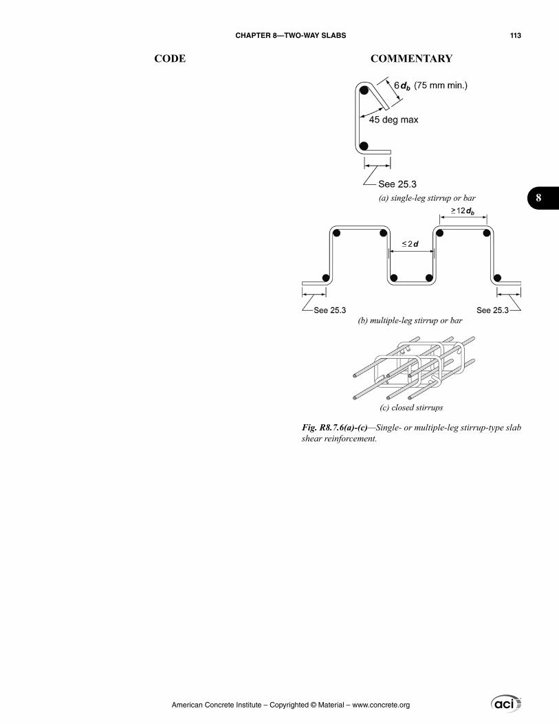
Fig. R8.7.6(a)-(c)—Single- or multiple-leg stirrup-type slab shear reinforcement.
American Concrete Institute – Copyrighted © Material – www.concrete.org
CHAPTER 8—TWO-WAY SLABS 113
CODE COMMENTARY
8
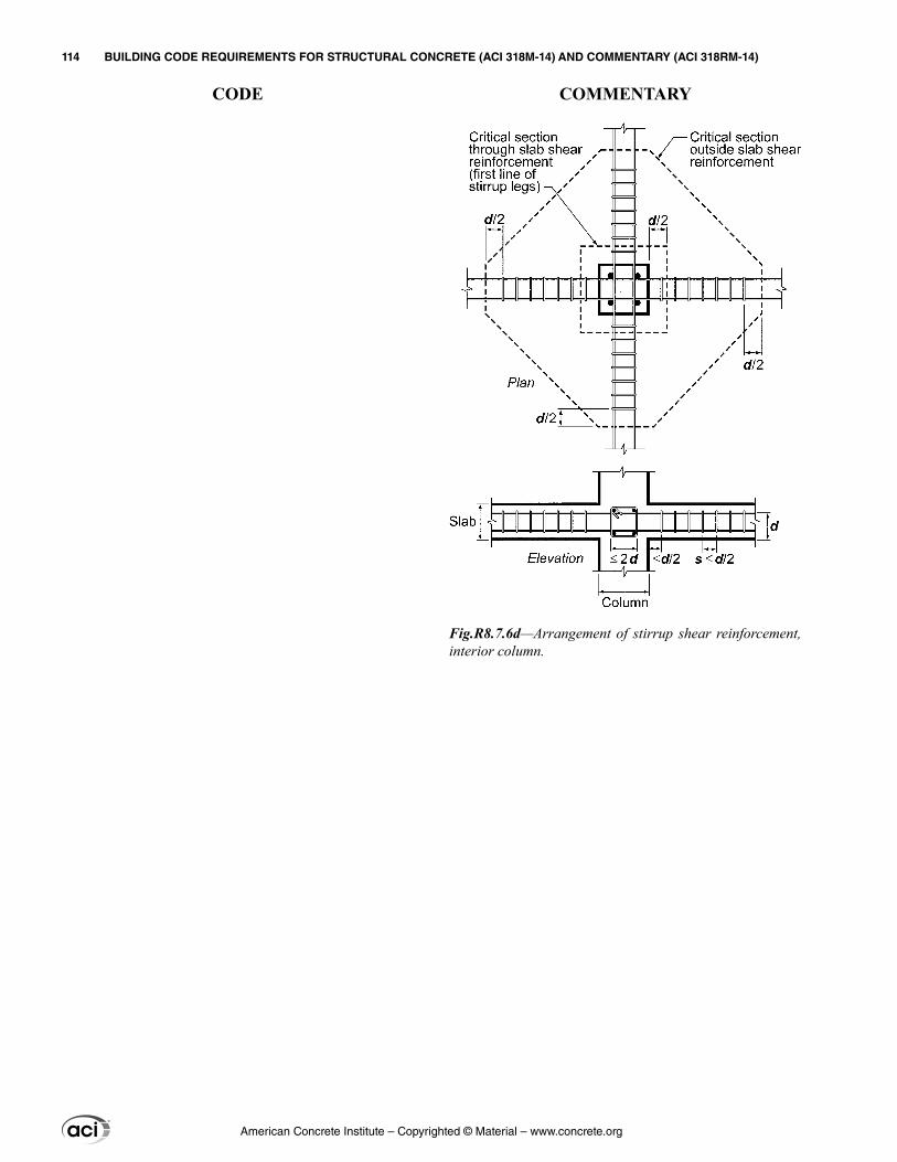
Fig.R8.7.6d—Arrangement of stirrup shear reinforcement, interior column.
American Concrete Institute – Copyrighted © Material – www.concrete.org
114 BUILDING CODE REQUIREMENTS FOR STRUCTURAL CONCRETE (ACI 318M-14) AND COMMENTARY (ACI 318RM-14)
CODE COMMENTARY
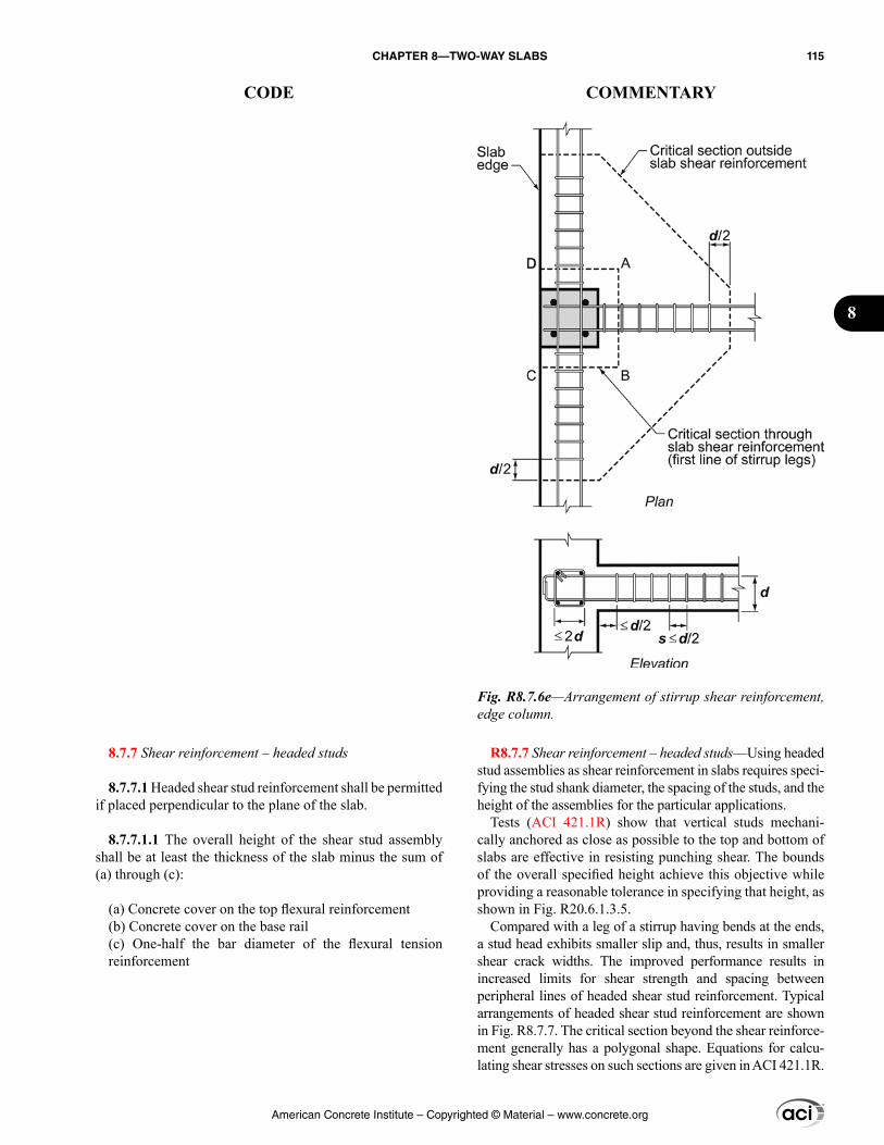
R8.7.7 Shear reinforcement – headed studs—Using headed stud assemblies as shear reinforcement in slabs requires speci-fying the stud shank diameter, the spacing of the studs, and the height of the assemblies for the particular applications.
Tests (ACI 421.1R) show that vertical studs mechani-cally anchored as close as possible to the top and bottom of slabs are effective in resisting punching shear. The bounds of the overall specified height achieve this objective while providing a reasonable tolerance in specifying that height, as shown in Fig. R20.6.1.3.5.
Compared with a leg of a stirrup having bends at the ends, a stud head exhibits smaller slip and, thus, results in smaller shear crack widths. The improved performance results in increased limits for shear strength and spacing between peripheral lines of headed shear stud reinforcement. Typical arrangements of headed shear stud reinforcement are shown in Fig. R8.7.7. The critical section beyond the shear reinforce-ment generally has a polygonal shape. Equations for calcu-lating shear stresses on such sections are given in ACI 421.1R.
8.7.7 Shear reinforcement – headed studs
8.7.7.1 Headed shear stud reinforcement shall be permitted if placed perpendicular to the plane of the slab.
8.7.7.1.1 The overall height of the shear stud assembly shall be at least the thickness of the slab minus the sum of (a) through (c):
(a) Concrete cover on the top flexural reinforcement(b) Concrete cover on the base rail(c) One-half the bar diameter of the flexural tension reinforcement
Fig. R8.7.6e—Arrangement of stirrup shear reinforcement, edge column.
American Concrete Institute – Copyrighted © Material – www.concrete.org
CHAPTER 8—TWO-WAY SLABS 115
CODE COMMENTARY
8
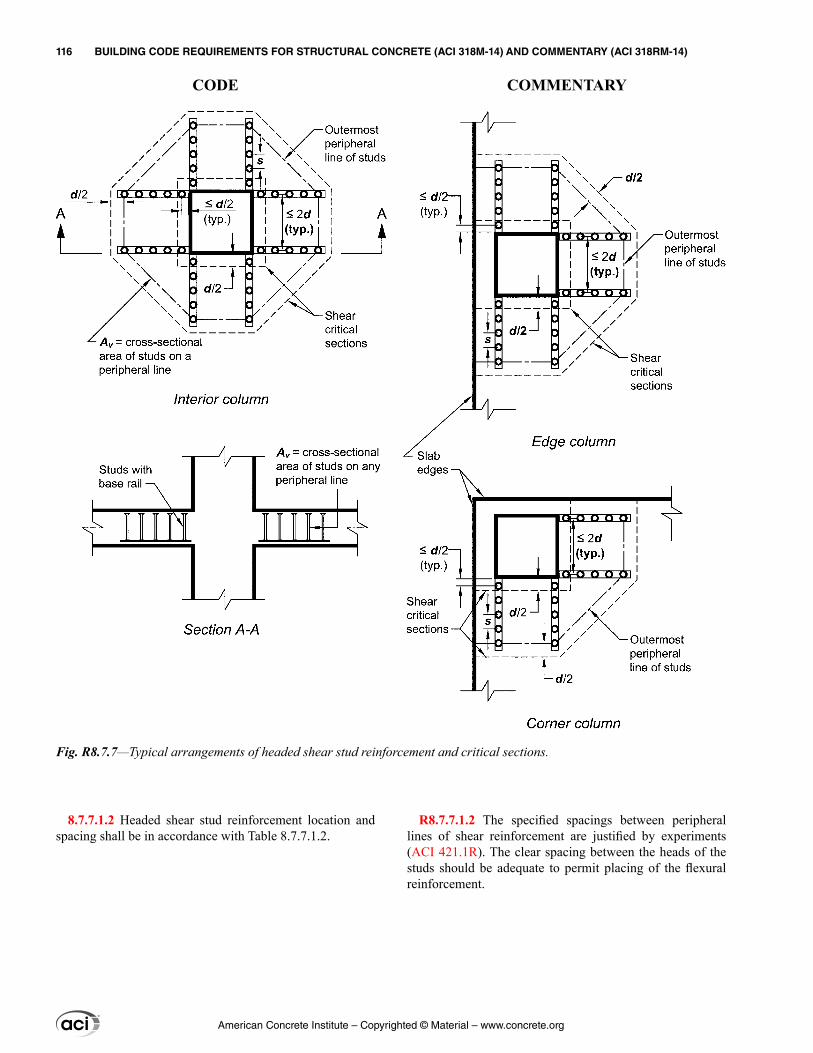
R8.7.7.1.2 The specified spacings between peripheral lines of shear reinforcement are justified by experiments (ACI 421.1R). The clear spacing between the heads of the studs should be adequate to permit placing of the flexural reinforcement.
8.7.7.1.2 Headed shear stud reinforcement location and spacing shall be in accordance with Table 8.7.7.1.2.
Fig. R8.7.7—Typical arrangements of headed shear stud reinforcement and critical sections.
American Concrete Institute – Copyrighted © Material – www.concrete.org
116 BUILDING CODE REQUIREMENTS FOR STRUCTURAL CONCRETE (ACI 318M-14) AND COMMENTARY (ACI 318RM-14)
CODE COMMENTARY
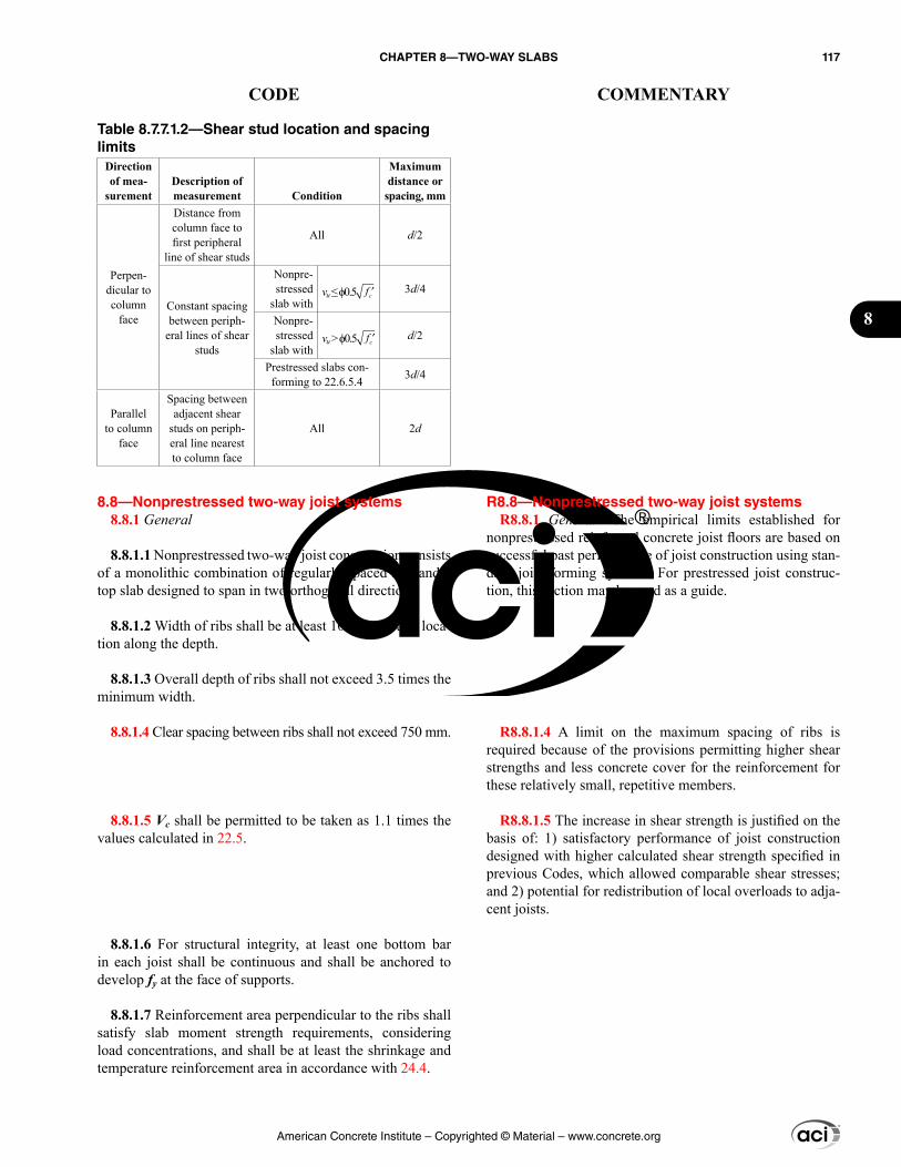
R8.8—Nonprestressed two-way joist systems R8.8.1 General—The empirical limits established for
nonprestressed reinforced concrete joist floors are based on successful past performance of joist construction using stan-dard joist forming systems. For prestressed joist construc-tion, this section may be used as a guide.
R8.8.1.4 A limit on the maximum spacing of ribs is required because of the provisions permitting higher shear strengths and less concrete cover for the reinforcement for these relatively small, repetitive members.
R8.8.1.5 The increase in shear strength is justified on the basis of: 1) satisfactory performance of joist construction designed with higher calculated shear strength specified in previous Codes, which allowed comparable shear stresses; and 2) potential for redistribution of local overloads to adja-cent joists.
Table 8.7.7.1.2—Shear stud location and spacing limits
Direction of mea-
surementDescription of measurement Condition
Maximum distance or
spacing, mm
Perpen-dicular to column
face
Distance from column face to first peripheral
line of shear studs
All d/2
Constant spacing between periph-
eral lines of shear studs
Nonpre-stressed
slab withvu ≤ ϕ0.5 ′fc 3d/4
Nonpre-stressed
slab withvu > ϕ0.5 ′fc d/2
Prestressed slabs con-forming to 22.6.5.4 3d/4
Parallel to column
face
Spacing between adjacent shear
studs on periph-eral line nearest to column face
All 2d
8.8—Nonprestressed two-way joist systems 8.8.1 General
8.8.1.1 Nonprestressed two-way joist construction consists of a monolithic combination of regularly spaced ribs and a top slab designed to span in two orthogonal directions.
8.8.1.2 Width of ribs shall be at least 100 mm at any loca-tion along the depth.
8.8.1.3 Overall depth of ribs shall not exceed 3.5 times the minimum width.
8.8.1.4 Clear spacing between ribs shall not exceed 750 mm.
8.8.1.5 Vc shall be permitted to be taken as 1.1 times the values calculated in 22.5.
8.8.1.6 For structural integrity, at least one bottom bar in each joist shall be continuous and shall be anchored to develop fy at the face of supports.
8.8.1.7 Reinforcement area perpendicular to the ribs shall satisfy slab moment strength requirements, considering load concentrations, and shall be at least the shrinkage and temperature reinforcement area in accordance with 24.4.
American Concrete Institute – Copyrighted © Material – www.concrete.org
CHAPTER 8—TWO-WAY SLABS 117
CODE COMMENTARY
8
8.8.1.8 Two-way joist construction not satisfying the limi-tations of 8.8.1.1 through 8.8.1.4 shall be designed as slabs and beams.
8.8.2 Joist systems with structural fillers
8.8.2.1 If permanent burned clay or concrete tile fillers of material having a unit compressive strength at least equal to fc′ in the joists are used, 8.8.2.1.1 and 8.8.2.1.2 shall apply.
8.8.2.1.1 Slab thickness over fillers shall be at least the greater of one-twelfth the clear distance between ribs and 40 mm.
8.8.2.1.2 For calculation of shear and negative moment strength, it shall be permitted to include the vertical shells of fillers in contact with the ribs. Other portions of fillers shall not be included in strength calculations.
8.8.3 Joist systems with other fillers
8.8.3.1 If fillers not complying with 8.8.2.1 or removable forms are used, slab thickness shall be at least the greater of one-twelfth the clear distance between ribs and 50 mm.
8.9—Lift-slab construction 8.9.1 In slabs constructed with lift-slab methods where it
is impractical to pass the tendons required by 8.7.5.6.1 or the bottom bars required by 8.7.4.2 or 8.7.5.6.3 through the column, at least two post-tensioned tendons or two bonded bottom bars or wires in each direction shall pass through the lifting collar as close to the column as practicable, and be continuous or spliced with full mechanical, full welded, or Class B tension splices. At exterior columns, the reinforce-ment shall be anchored at the lifting collar.
8.10—Direct design method
8.10.1 General
8.10.1.1 Two-way slabs satisfying the limits in 8.10.2 shall be permitted to be designed in accordance with this section.
R8.10—Direct design method The direct design method consists of a set of rules for
distributing moments to slab and beam sections to satisfy safety requirements and most serviceability requirements simultaneously. Three fundamental steps are involved as follows:
(1) Determination of the total factored static moment (8.10.3)(2) Distribution of the total factored static moment to negative and positive sections (8.10.4)(3) Distribution of the negative and positive factored moments to the column and middle strips and to the beams, if any (8.10.5 and 8.10.6). The distribution of moments to column and middle strips is also used in the equivalent frame method (8.11)
R8.10.1 General
R8.10.1.1 The direct design method was developed from considerations of theoretical procedures for the determina-
American Concrete Institute – Copyrighted © Material – www.concrete.org
118 BUILDING CODE REQUIREMENTS FOR STRUCTURAL CONCRETE (ACI 318M-14) AND COMMENTARY (ACI 318RM-14)
CODE COMMENTARY
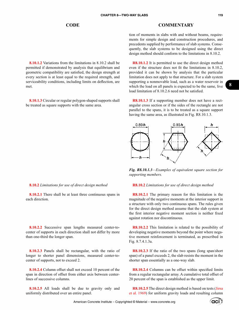
8.10.1.2 Variations from the limitations in 8.10.2 shall be permitted if demonstrated by analysis that equilibrium and geometric compatibility are satisfied, the design strength at every section is at least equal to the required strength, and serviceability conditions, including limits on deflection, are met.
8.10.1.3 Circular or regular polygon-shaped supports shall be treated as square supports with the same area.
8.10.2 Limitations for use of direct design method
8.10.2.1 There shall be at least three continuous spans in each direction.
8.10.2.2 Successive span lengths measured center-to-center of supports in each direction shall not differ by more than one-third the longer span.
8.10.2.3 Panels shall be rectangular, with the ratio of longer to shorter panel dimensions, measured center-to-center of supports, not to exceed 2.
8.10.2.4 Column offset shall not exceed 10 percent of the span in direction of offset from either axis between center-lines of successive columns.
8.10.2.5 All loads shall be due to gravity only and uniformly distributed over an entire panel.
tion of moments in slabs with and without beams, require-ments for simple design and construction procedures, and precedents supplied by performance of slab systems. Conse-quently, the slab systems to be designed using the direct design method should conform to the limitations in 8.10.2.
R8.10.1.2 It is permitted to use the direct design method even if the structure does not fit the limitations in 8.10.2, provided it can be shown by analysis that the particular limitation does not apply to that structure. For a slab system supporting a nonmovable load, such as a water reservoir in which the load on all panels is expected to be the same, live load limitation of 8.10.2.6 need not be satisfied.
R8.10.1.3 If a supporting member does not have a rect-angular cross section or if the sides of the rectangle are not parallel to the spans, it is to be treated as a square support having the same area, as illustrated in Fig. R8.10.1.3.
R8.10.2 Limitations for use of direct design method
R8.10.2.1 The primary reason for this limitation is the magnitude of the negative moments at the interior support in a structure with only two continuous spans. The rules given for the direct design method assume that the slab system at the first interior negative moment section is neither fixed against rotation nor discontinuous.
R8.10.2.2 This limitation is related to the possibility of developing negative moments beyond the point where nega-tive moment reinforcement is terminated, as prescribed in Fig. 8.7.4.1.3a.
R8.10.2.3 If the ratio of the two spans (long span/short span) of a panel exceeds 2, the slab resists the moment in the shorter span essentially as a one-way slab.
R8.10.2.4 Columns can be offset within specified limits from a regular rectangular array. A cumulative total offset of 20 percent of the span is established as the upper limit.
R8.10.2.5 The direct design method is based on tests (Jirsa et al. 1969) for uniform gravity loads and resulting column
Fig. R8.10.1.3—Examples of equivalent square section for supporting members.
American Concrete Institute – Copyrighted © Material – www.concrete.org
CHAPTER 8—TWO-WAY SLABS 119
CODE COMMENTARY
8
reactions determined by statics. Lateral loads, such as wind or those induced by earthquake, require a frame analysis. Inverted foundation mats designed as two-way slabs (13.3.4) involve application of known column loads. Therefore, even where the soil reaction is assumed to be uniform, a frame analysis should be performed.
R8.10.2.6 In most slab systems, the live-to-dead load ratio will be less than 2 and it will not be necessary to check the effects of pattern loading.
R8.10.2.7 The elastic distribution of moments will deviate significantly from those assumed in the direct design method unless the requirements for stiffness are satisfied.
R8.10.3 Total factored static moment for a span
R8.10.3.2 Equation (8.10.3.2) follows directly from Nich-ol’s derivation (Nichols 1914) with the simplifying assump-tion that the reactions are concentrated along the faces of the support perpendicular to the span considered. In general, it will be expedient to calculate static moments for two adjacent half-panels that include a column strip with a half middle strip along each side.
R8.10.4 Distribution of total factored static moment
8.10.2.6 Unfactored live load shall not exceed two times the unfactored dead load.
8.10.2.7 For a panel with beams between supports on all sides, Eq. (8.10.2.7a) shall be satisfied for beams in the two perpendicular directions.
2
1 22
2 1
0.2 5.0f
f
α≤ ≤
αl
l (8.10.2.7a)
where αf1 and αf2 are calculated by:
cb bf
cs s
E IE I
α = (8.10.2.7b)
8.10.3 Total factored static moment for a span
8.10.3.1 Total factored static moment Mo for a span shall be calculated for a strip bounded laterally by the panel centerline on each side of the centerline of supports.
8.10.3.2 The absolute sum of positive and average nega-tive Mu in each direction shall be at least:
2
2
8u n
oq
M =l l
(8.10.3.2)
8.10.3.2.1 In Eq. (8.10.3.2), ℓn is the clear span length in the direction that moments are considered, shall extend from face to face of columns, capitals, brackets, or walls, and shall be at least 0.65ℓ1.
8.10.3.2.2 In Eq. (8.10.3.2), if the transverse span of panels on either side of the centerline of supports varies, ℓ2 shall be taken as the average of adjacent transverse spans.
8.10.3.2.3 In Eq. (8.10.3.2), if the span adjacent and parallel to a slab edge is being considered, the distance from edge to panel centerline shall be substituted for ℓ2.
8.10.4 Distribution of total factored static moment
8.10.4.1 In an interior span, Mo shall be distributed as follows: 0.65Mo to negative moment and 0.35Mo to positive moment.
American Concrete Institute – Copyrighted © Material – www.concrete.org
120 BUILDING CODE REQUIREMENTS FOR STRUCTURAL CONCRETE (ACI 318M-14) AND COMMENTARY (ACI 318RM-14)
CODE COMMENTARY
R8.10.4.2 The moment coefficients for an end span are based on the equivalent column stiffness expressions from Corley et al. (1961), Jirsa et al. (1963), and Corley and Jirsa (1970). The coefficients for an unrestrained edge would be used, for example, if the slab were simply supported on a masonry or concrete wall. Those for a fully restrained edge would apply if the slab were constructed integrally with a concrete wall having a flexural stiffness so large compared to that of the slab that little rotation occurs at the slab-to-wall connection.
For other than unrestrained or fully restrained edges, coefficients in the table were selected to be near the upper bound of the range for positive moments and interior nega-tive moments. As a result, exterior negative moments were usually closer to a lower bound. The exterior nega-tive moment strength for most slab systems is governed by minimum reinforcement to control cracking. The coef-ficients in the table have been adjusted so that the absolute sum of the positive and average moments equal Mo.
In the 1977 Code, distribution factors defined as a func-tion of the stiffness ratio of the equivalent exterior support were used for proportioning the total static moment Mo in an end span. This approach may be used in place of values in this provision.
R8.10.4.3 This provision permits a reduction up to 10 percent in negative or positive factored moments, calcu-lated in accordance with 8.10.4, provided that the total static moment for a panel in the direction considered is not less than Mo required by Eq. (8.10.3.2). This is intended to recog-nize a limited amount of inelastic behavior and moment redistribution can occur in slabs that are analyzed with the direct design method.
Moment redistribution as permitted by 6.6.5 is not intended for use where approximate values for moments are used.
R8.10.4.5 The differences in slab moment on either side of a column or other type of support should be accounted for in the design of the support. If an analysis is made to distribute unbalanced moments, flexural stiffness may be obtained on the basis of the gross concrete section of the members involved.
R8.10.4.6 Moments perpendicular to, and at the edge of, the slab structure should be transmitted to the supporting columns or walls. Torsional stresses caused by the moment assigned to the slab should be investigated.
R8.10.5 Factored moments in column strips—The rules given for assigning moments to the column strips, beams, and middle strips are based on studies (Gamble 1972) of moments in linearly elastic slabs with different beam stiff-
8.10.4.2 In an end span, Mo shall be distributed in accor-dance with Table 8.10.4.2.
Table 8.10.4.2—Distribution coefficients for end spans
Exterior edge
unrestrained
Slab with beams
between all supports
Slab without beams between
interior supportsExterior
edge fully restrained
Without edge beam
With edge beam
Interior negative 0.75 0.70 0.70 0.70 0.65
Positive 0.63 0.57 0.52 0.50 0.35Exterior negative 0 0.16 0.26 0.30 0.65
8.10.4.3 Modification of negative and positive factored moments by up to 10 percent shall be permitted if the total factored static moment for a panel, Mo, in the direc-tion considered is at least that calculated by Eq. (8.10.3.2). Moment redistribution in accordance with 6.6.5 is not permitted.
8.10.4.4 Critical section for negative Mu shall be at the face of rectangular supports.
8.10.4.5 Negative Mu shall be the greater of the two inte-rior negative Mu calculated for spans framing into a common support unless an analysis is made to distribute the unbal-anced moment in accordance with stiffnesses of adjoining elements.
8.10.4.6 Edge beams or edges of slabs shall be designed to resist in torsion their share of exterior negative Mu.
8.10.5 Factored moments in column strips
8.10.5.1 The column strip shall resist the portion of inte-rior negative Mu in accordance with Table 8.10.5.1.
American Concrete Institute – Copyrighted © Material – www.concrete.org
CHAPTER 8—TWO-WAY SLABS 121
CODE COMMENTARY
8
nesses tempered by the moment coefficients that have been used successfully.
For the purpose of establishing moments in the half column strip adjacent to an edge supported by a wall, ℓn in Eq. (8.10.3.2) may be assumed equal to ℓn of the parallel adjacent column to column span, and the wall may be considered as a beam having a moment of inertia, Ib, equal to infinity.
R8.10.5.2 The effect of the torsional stiffness parameter βt is to assign all of the exterior negative factored moment to the column strip, and none to the middle strip, unless the beam torsional stiffness is high relative to the flexural stiff-ness of the supported slab. In the definition of βt, the shear modulus has been taken as Ecb/2.
Where walls are used as supports along column lines, they can be regarded as very stiff beams with an αf1ℓ2/ℓ1 value greater than 1. Where the exterior support consists of a wall perpendicular to the direction in which moments are being determined, βt may be taken as zero if the wall is of masonry without torsional resistance, and βt may be taken as 2.5 for a concrete wall with great torsional resistance that is mono-lithic with the slab.
R8.10.5.7 Factored moments in beams—Loads assigned directly to beams are in addition to the uniform dead load
Table 8.10.5.1—Portion of interior negative Mu in column strip
αf1ℓ2/ℓ1
ℓ2/ℓ1
0.5 1.0 2.00 0.75 0.75 0.75
≥1.0 0.90 0.75 0.45Note: Linear interpolations shall be made between values shown.
8.10.5.2 The column strip shall resist the portion of exterior negative Mu in accordance with Table 8.10.5.2.
Table 8.10.5.2—Portion of exterior negative Mu in column strip
αf1ℓ2/ℓ1 βt
ℓ2/ℓ1
0.5 1.0 2.0
00 1.0 1.0 1.0
≥2.5 0.75 0.75 0.75
≥1.00 1.0 1.0 1.0
≥2.5 0.90 0.75 0.45Note: Linear interpolations shall be made between values shown. βt is calculated using Eq. (8.10.5.2a), where C is calculated using Eq. (8.10.5.2b).
2
cbt
cs s
E CE I
β = (8.10.5.2a)
3
1 0.633
x x yCy
= Σ −
(8.10.5.2b)
8.10.5.3 For T- or L-sections, it shall be permitted to calculate the constant C in Eq. (8.10.5.2b) by dividing the section, as given in 8.4.1.8, into separate rectangular parts and summing the values of C for each part.
8.10.5.4 If the width of the column or wall is at least (3/4)ℓ2, negative Mu shall be uniformly distributed across ℓ2.
8.10.5.5 The column strip shall resist the portion of posi-tive Mu in accordance with Table 8.10.5.5.
Table 8.10.5.5—Portion of positive Mu in column strip
αf1ℓ2/ℓ1
ℓ2/ℓ1
0.5 1.0 2.0
0 0.60 0.60 0.60
≥1.0 0.90 0.75 0.45
Note: Linear interpolations shall be made between values shown.
8.10.5.6 For slabs with beams between supports, the slab portion of column strips shall resist column strip moments not resisted by beams.
8.10.5.7 Factored moments in beams
American Concrete Institute – Copyrighted © Material – www.concrete.org
122 BUILDING CODE REQUIREMENTS FOR STRUCTURAL CONCRETE (ACI 318M-14) AND COMMENTARY (ACI 318RM-14)
CODE COMMENTARY
of the slab; uniform superimposed dead loads such as the ceiling, floor finish, or assumed equivalent partition loads; and uniform live loads. All of these loads are normally included with qu in Eq. (8.10.3.2). Line loads applied directly to beams include partition walls over or along beam center-lines and additional dead load of the projecting beam stem. Concentrated loads include posts above or hangers below the beams. For the purpose of assigning directly applied loads, only loads located within the width of the beam stem should be considered as directly applied to the beams. The effective width of a beam as defined in 8.4.1.8 is solely for strength and relative stiffness calculations. Line loads and concentrated loads located on the slab away from the beam stem require consideration to determine their apportionment to slab and beams. Also refer to R8.10.5.
R8.10.6 Factored moments in middle strips—Refer to R8.10.5.
R8.10.7 Factored moments in columns and walls—Design and detailing of the reinforcement transferring the moment from the slab to the edge column is critical to both the performance and the safety of flat slabs or flat plates without edge beams or cantilever slabs. It is important that complete design details be shown in the construction documents, such as concentration of reinforcement over the column by closer spacing, or additional reinforcement.
R8.10.7.2 Equation (8.10.7.2) refers to two adjoining spans, with one span longer than the other, and with full dead load plus one-half live load applied on the longer span and only dead load applied on the shorter span.
R8.10.7.3 Analyses of slab systems indicate that the rela-tive stiffnesses of the slab, beams, and column influence the amount of moment transferred to the support under gravity load conditions, but only over a narrow range. For typical slab configurations, a realistic upper limit between the values provided in Table 8.10.4.2 for unrestrained and fully restrained edge conditions is 0.3Mo.
8.10.5.7.1 Beams between supports shall resist the portion of column strip Mu in accordance with Table 8.10.5.7.1.
Table 8.10.5.7.1—Portion of column strip Mu in beams
αf1ℓ2/ℓ1 Distribution coefficient0 0
≥1.0 0.85Note: Linear interpolation shall be made between values shown.
8.10.5.7.2 In addition to moments calculated according to 8.10.5.7.1, beams shall resist moments caused by factored loads applied directly to the beams, including the weight of the beam stem above and below the slab.
8.10.6 Factored moments in middle strips
8.10.6.1 That portion of negative and positive factored moments not resisted by column strips shall be proportion-ately assigned to corresponding half middle strips.
8.10.6.2 Each middle strip shall resist the sum of the moments assigned to its two half middle strips.
8.10.6.3 A middle strip adjacent and parallel to a wall-supported edge shall resist twice the moment assigned to the half middle strip corresponding to the first row of interior supports.
8.10.7 Factored moments in columns and walls
8.10.7.1 Columns and walls built integrally with a slab system shall resist moments caused by factored loads on the slab system.
8.10.7.2 At an interior support, columns or walls above and below the slab shall resist the factored moment calcu-lated by Eq. (8.10.7.2) in direct proportion to their stiff-nesses unless a general analysis is made.
Msc = 0.07[(qDu + 0.5qLu)ℓ2ℓn2 – qDu′ℓ2′(ℓn′)2] (8.10.7.2)
where qDu′, ℓ2′, and ℓn′ refer to the shorter span.
8.10.7.3 The gravity load moment to be transferred between slab and edge column in accordance with 8.4.2.3 shall not be less than 0.3Mo.
American Concrete Institute – Copyrighted © Material – www.concrete.org
CHAPTER 8—TWO-WAY SLABS 123
CODE COMMENTARY
8
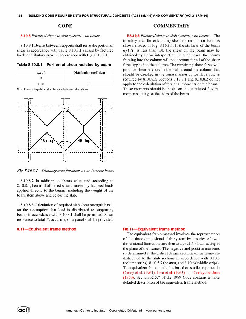
R8.10.8 Factored shear in slab systems with beams—The tributary area for calculating shear on an interior beam is shown shaded in Fig. 8.10.8.1. If the stiffness of the beam αf1ℓ2/ℓ1 is less than 1.0, the shear on the beam may be obtained by linear interpolation. In such cases, the beams framing into the column will not account for all of the shear force applied to the column. The remaining shear force will produce shear stresses in the slab around the column that should be checked in the same manner as for flat slabs, as required by 8.10.8.3. Sections 8.10.8.1 and 8.10.8.2 do not apply to the calculation of torsional moments on the beams. These moments should be based on the calculated flexural moments acting on the sides of the beam.
R8.11—Equivalent frame method The equivalent frame method involves the representation
of the three-dimensional slab system by a series of two-dimensional frames that are then analyzed for loads acting in the plane of the frames. The negative and positive moments so determined at the critical design sections of the frame are distributed to the slab sections in accordance with 8.10.5 (column strips), 8.10.5.7 (beams), and 8.10.6 (middle strips). The equivalent frame method is based on studies reported in Corley et al. (1961), Jirsa et al. (1963), and Corley and Jirsa (1970). Section R13.7 of the 1989 Code contains a more detailed description of the equivalent frame method.
8.10.8 Factored shear in slab systems with beams
8.10.8.1 Beams between supports shall resist the portion of shear in accordance with Table 8.10.8.1 caused by factored loads on tributary areas in accordance with Fig. 8.10.8.1.
Table 8.10.8.1—Portion of shear resisted by beam
αf1ℓ2/ℓ1 Distribution coefficient
0 0
≥1.0 1.0Note: Linear interpolation shall be made between values shown.
8.10.8.2 In addition to shears calculated according to 8.10.8.1, beams shall resist shears caused by factored loads applied directly to the beams, including the weight of the beam stem above and below the slab.
8.10.8.3 Calculation of required slab shear strength based on the assumption that load is distributed to supporting beams in accordance with 8.10.8.1 shall be permitted. Shear resistance to total Vu occurring on a panel shall be provided.
8.11—Equivalent frame method
Fig. 8.10.8.1—Tributary area for shear on an interior beam.
American Concrete Institute – Copyrighted © Material – www.concrete.org
124 BUILDING CODE REQUIREMENTS FOR STRUCTURAL CONCRETE (ACI 318M-14) AND COMMENTARY (ACI 318RM-14)
CODE COMMENTARY
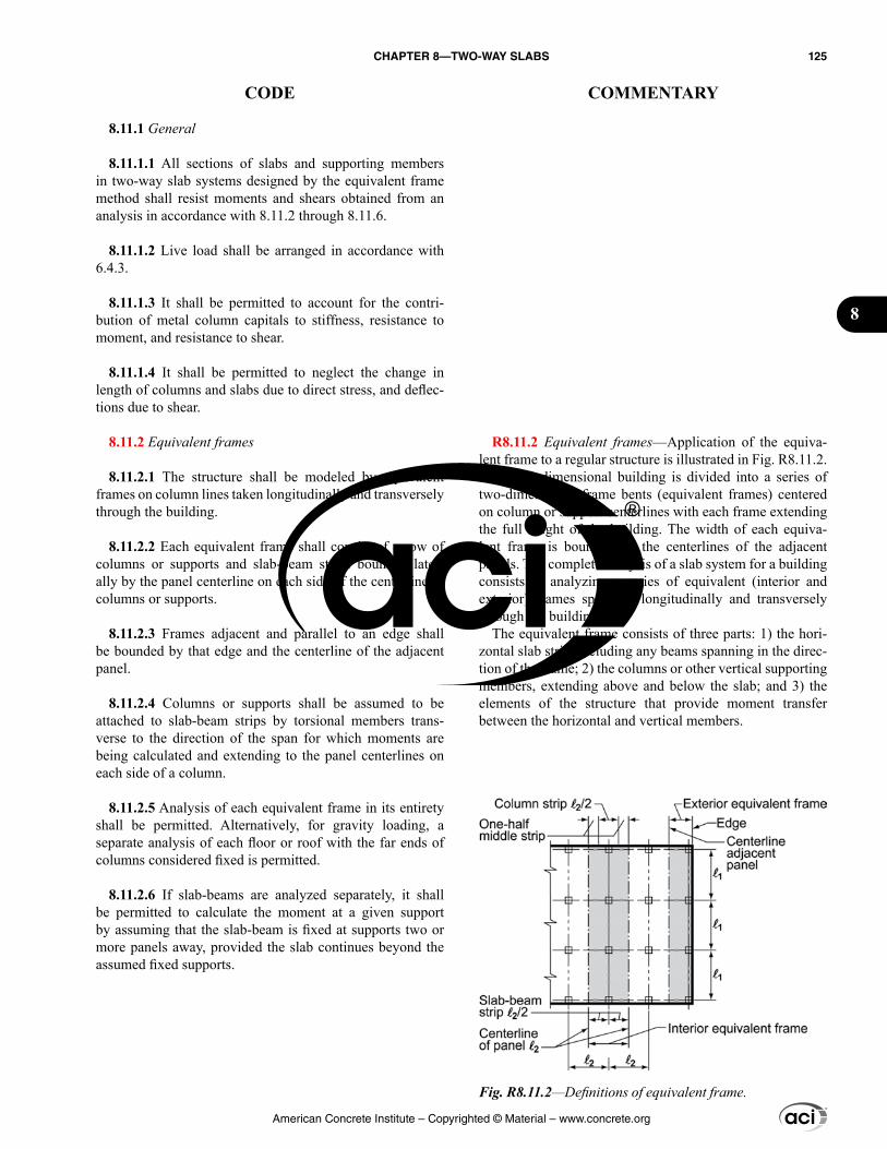
8.11.1 General
8.11.1.1 All sections of slabs and supporting members in two-way slab systems designed by the equivalent frame method shall resist moments and shears obtained from an analysis in accordance with 8.11.2 through 8.11.6.
8.11.1.2 Live load shall be arranged in accordance with 6.4.3.
8.11.1.3 It shall be permitted to account for the contri-bution of metal column capitals to stiffness, resistance to moment, and resistance to shear.
8.11.1.4 It shall be permitted to neglect the change in length of columns and slabs due to direct stress, and deflec-tions due to shear.
8.11.2 Equivalent frames
8.11.2.1 The structure shall be modeled by equivalent frames on column lines taken longitudinally and transversely through the building.
8.11.2.2 Each equivalent frame shall consist of a row of columns or supports and slab-beam strips bounded later-ally by the panel centerline on each side of the centerline of columns or supports.
8.11.2.3 Frames adjacent and parallel to an edge shall be bounded by that edge and the centerline of the adjacent panel.
8.11.2.4 Columns or supports shall be assumed to be attached to slab-beam strips by torsional members trans-verse to the direction of the span for which moments are being calculated and extending to the panel centerlines on each side of a column.
8.11.2.5 Analysis of each equivalent frame in its entirety shall be permitted. Alternatively, for gravity loading, a separate analysis of each floor or roof with the far ends of columns considered fixed is permitted.
8.11.2.6 If slab-beams are analyzed separately, it shall be permitted to calculate the moment at a given support by assuming that the slab-beam is fixed at supports two or more panels away, provided the slab continues beyond the assumed fixed supports.
R8.11.2 Equivalent frames—Application of the equiva-lent frame to a regular structure is illustrated in Fig. R8.11.2. The three-dimensional building is divided into a series of two-dimensional frame bents (equivalent frames) centered on column or support centerlines with each frame extending the full height of the building. The width of each equiva-lent frame is bounded by the centerlines of the adjacent panels. The complete analysis of a slab system for a building consists of analyzing a series of equivalent (interior and exterior) frames spanning longitudinally and transversely through the building.
The equivalent frame consists of three parts: 1) the hori-zontal slab strip, including any beams spanning in the direc-tion of the frame; 2) the columns or other vertical supporting members, extending above and below the slab; and 3) the elements of the structure that provide moment transfer between the horizontal and vertical members.
Fig. R8.11.2—Definitions of equivalent frame.
American Concrete Institute – Copyrighted © Material – www.concrete.org
CHAPTER 8—TWO-WAY SLABS 125
CODE COMMENTARY
8
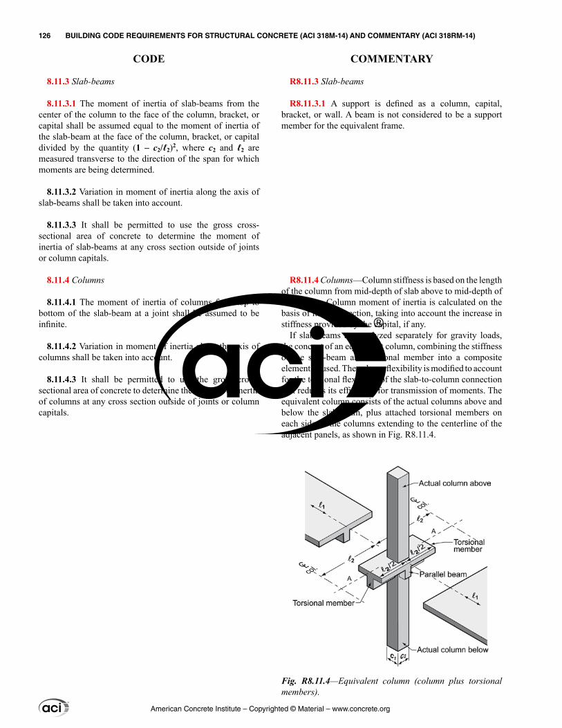
8.11.3 Slab-beams
8.11.3.1 The moment of inertia of slab-beams from the center of the column to the face of the column, bracket, or capital shall be assumed equal to the moment of inertia of the slab-beam at the face of the column, bracket, or capital divided by the quantity (1 – c2/ℓ2)2, where c2 and ℓ2 are measured transverse to the direction of the span for which moments are being determined.
8.11.3.2 Variation in moment of inertia along the axis of slab-beams shall be taken into account.
8.11.3.3 It shall be permitted to use the gross cross-sectional area of concrete to determine the moment of inertia of slab-beams at any cross section outside of joints or column capitals.
8.11.4 Columns
8.11.4.1 The moment of inertia of columns from top to bottom of the slab-beam at a joint shall be assumed to be infinite.
8.11.4.2 Variation in moment of inertia along the axis of columns shall be taken into account.
8.11.4.3 It shall be permitted to use the gross cross-sectional area of concrete to determine the moment of inertia of columns at any cross section outside of joints or column capitals.
R8.11.3 Slab-beams
R8.11.3.1 A support is defined as a column, capital, bracket, or wall. A beam is not considered to be a support member for the equivalent frame.
R8.11.4 Columns—Column stiffness is based on the length of the column from mid-depth of slab above to mid-depth of slab below. Column moment of inertia is calculated on the basis of its cross section, taking into account the increase in stiffness provided by the capital, if any.
If slab-beams are analyzed separately for gravity loads, the concept of an equivalent column, combining the stiffness of the slab-beam and torsional member into a composite element, is used. The column flexibility is modified to account for the torsional flexibility of the slab-to-column connection that reduces its efficiency for transmission of moments. The equivalent column consists of the actual columns above and below the slab-beam, plus attached torsional members on each side of the columns extending to the centerline of the adjacent panels, as shown in Fig. R8.11.4.
Fig. R8.11.4—Equivalent column (column plus torsional members).
American Concrete Institute – Copyrighted © Material – www.concrete.org
126 BUILDING CODE REQUIREMENTS FOR STRUCTURAL CONCRETE (ACI 318M-14) AND COMMENTARY (ACI 318RM-14)
CODE COMMENTARY
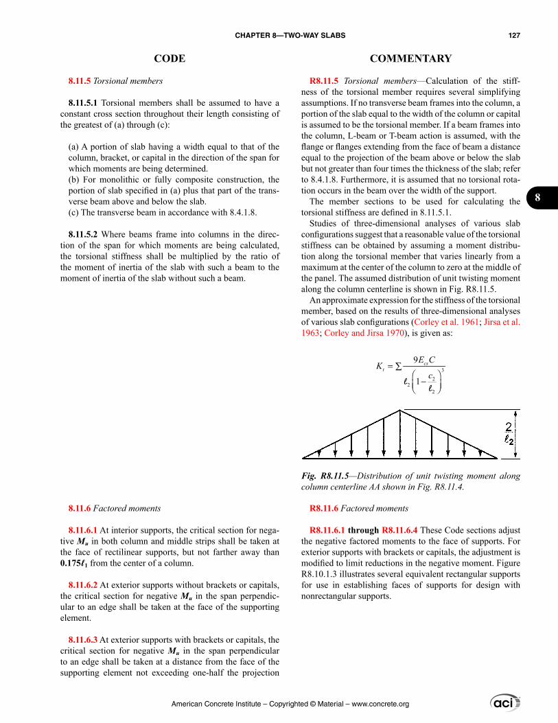
R8.11.5 Torsional members—Calculation of the stiff-ness of the torsional member requires several simplifying assumptions. If no transverse beam frames into the column, a portion of the slab equal to the width of the column or capital is assumed to be the torsional member. If a beam frames into the column, L-beam or T-beam action is assumed, with the flange or flanges extending from the face of beam a distance equal to the projection of the beam above or below the slab but not greater than four times the thickness of the slab; refer to 8.4.1.8. Furthermore, it is assumed that no torsional rota-tion occurs in the beam over the width of the support.
The member sections to be used for calculating the torsional stiffness are defined in 8.11.5.1.
Studies of three-dimensional analyses of various slab configurations suggest that a reasonable value of the torsional stiffness can be obtained by assuming a moment distribu-tion along the torsional member that varies linearly from a maximum at the center of the column to zero at the middle of the panel. The assumed distribution of unit twisting moment along the column centerline is shown in Fig. R8.11.5.
An approximate expression for the stiffness of the torsional member, based on the results of three-dimensional analyses of various slab configurations (Corley et al. 1961; Jirsa et al. 1963; Corley and Jirsa 1970), is given as:
3
22
2
9
1
cst
E CK
c= ∑
−
ll
R8.11.6 Factored moments
R8.11.6.1 through R8.11.6.4 These Code sections adjust the negative factored moments to the face of supports. For exterior supports with brackets or capitals, the adjustment is modified to limit reductions in the negative moment. Figure R8.10.1.3 illustrates several equivalent rectangular supports for use in establishing faces of supports for design with nonrectangular supports.
8.11.5 Torsional members
8.11.5.1 Torsional members shall be assumed to have a constant cross section throughout their length consisting of the greatest of (a) through (c):
(a) A portion of slab having a width equal to that of the column, bracket, or capital in the direction of the span for which moments are being determined.(b) For monolithic or fully composite construction, the portion of slab specified in (a) plus that part of the trans-verse beam above and below the slab.(c) The transverse beam in accordance with 8.4.1.8.
8.11.5.2 Where beams frame into columns in the direc-tion of the span for which moments are being calculated, the torsional stiffness shall be multiplied by the ratio of the moment of inertia of the slab with such a beam to the moment of inertia of the slab without such a beam.
8.11.6 Factored moments
8.11.6.1 At interior supports, the critical section for nega-tive Mu in both column and middle strips shall be taken at the face of rectilinear supports, but not farther away than 0.175ℓ1 from the center of a column.
8.11.6.2 At exterior supports without brackets or capitals, the critical section for negative Mu in the span perpendic-ular to an edge shall be taken at the face of the supporting element.
8.11.6.3 At exterior supports with brackets or capitals, the critical section for negative Mu in the span perpendicular to an edge shall be taken at a distance from the face of the supporting element not exceeding one-half the projection
Fig. R8.11.5—Distribution of unit twisting moment along column centerline AA shown in Fig. R8.11.4.
American Concrete Institute – Copyrighted © Material – www.concrete.org
CHAPTER 8—TWO-WAY SLABS 127
CODE COMMENTARY
8
of the bracket or capital beyond the face of the supporting element.
8.11.6.4 Circular or regular polygon-shaped supports shall be assumed to be square supports with the same area for location of critical section for negative design moment.
8.11.6.5 Where slab systems within limitations of 8.10.2 are analyzed by the equivalent frame method, it shall be permitted to reduce the calculated moments in such propor-tion that the absolute sum of the positive and average nega-tive design moments need not exceed the value obtained from Eq. (8.10.3.2).
8.11.6.6 It shall be permitted to distribute moments at crit-ical sections to column strips, beams, and middle strips in accordance with the direct design method in 8.10, provided that Eq. (8.10.2.7a) is satisfied.
R8.11.6.5 This provision is based on the principle that if two different methods are prescribed to obtain a particular answer, the Code should not require a value greater than the least acceptable value. Due to the long satisfactory experi-ence with designs having total factored static moments not exceeding those given by Eq. (8.10.3.2), it is considered that these values are satisfactory for design if applicable limita-tions are met.
American Concrete Institute – Copyrighted © Material – www.concrete.org
128 BUILDING CODE REQUIREMENTS FOR STRUCTURAL CONCRETE (ACI 318M-14) AND COMMENTARY (ACI 318RM-14)
CODE COMMENTARY
CHAPTER 9—BEAMS
9.1—Scope 9.1.1 This chapter shall apply to the design of nonpre-
stressed and prestressed beams, including:
(a) Composite beams of concrete elements constructed in separate placements but connected so that all elements resist loads as a unit(b) One-way joist systems in accordance with 9.8(c) Deep beams in accordance with 9.9
9.2—General 9.2.1 Materials
9.2.1.1 Design properties for concrete shall be selected to be in accordance with Chapter 19.
9.2.1.2 Design properties for steel reinforcement shall be selected to be in accordance with Chapter 20.
9.2.1.3 Materials, design, and detailing requirements for embedments in concrete shall be in accordance with 20.7.
9.2.2 Connection to other members
9.2.2.1 For cast-in-place construction, beam-column and slab-column joints shall satisfy Chapter 15.
9.2.2.2 For precast construction, connections shall satisfy the force transfer requirements of 16.2.
9.2.3 Stability
9.2.3.1 If a beam is not continuously laterally braced, (a) and (b) shall be satisfied:
(a) Spacing of lateral bracing shall not exceed 50 times the least width of compression flange or face.(b) Spacing of lateral bracing shall take into account effects of eccentric loads.
9.2.3.2 In prestressed beams, buckling of thin webs and flanges shall be considered. If there is intermittent contact between prestressed reinforcement and an oversize duct, member buckling between contact points shall be considered.
R9—BEAMS
R9.1—Scope R9.1.1 Composite structural steel-concrete beams are
not covered in this chapter. Design provisions for such composite beams are covered in AISC 360.
R9.2—General
R9.2.3 Stability
R9.2.3.1 Tests (Hansell and Winter 1959; Sant and Blet-zacker 1961) have shown that laterally unbraced reinforced concrete beams, even when very deep and narrow, will not fail prematurely by lateral buckling, provided the beams are loaded without lateral eccentricity that causes torsion.
Laterally unbraced beams are frequently loaded eccentri-cally or with slight inclination. Stresses and deformations by such loading become detrimental for narrow, deep beams with long unsupported lengths. Lateral supports spaced closer than 50b may be required for such loading conditions.
R9.2.3.2 In post-tensioned members where the prestressed reinforcement has intermittent contact with an oversize duct, the member can buckle due to the axial prestressing force, as the member can deflect laterally while the prestressed reinforcement does not. If the prestressed reinforcement is in continuous contact with the member being prestressed or is part of an unbonded tendon with the sheathing not excessively larger than the prestressed reinforcement, the prestressing force cannot buckle the member.
American Concrete Institute – Copyrighted © Material – www.concrete.org
CHAPTER 9—BEAMS 129
CODE COMMENTARY
9
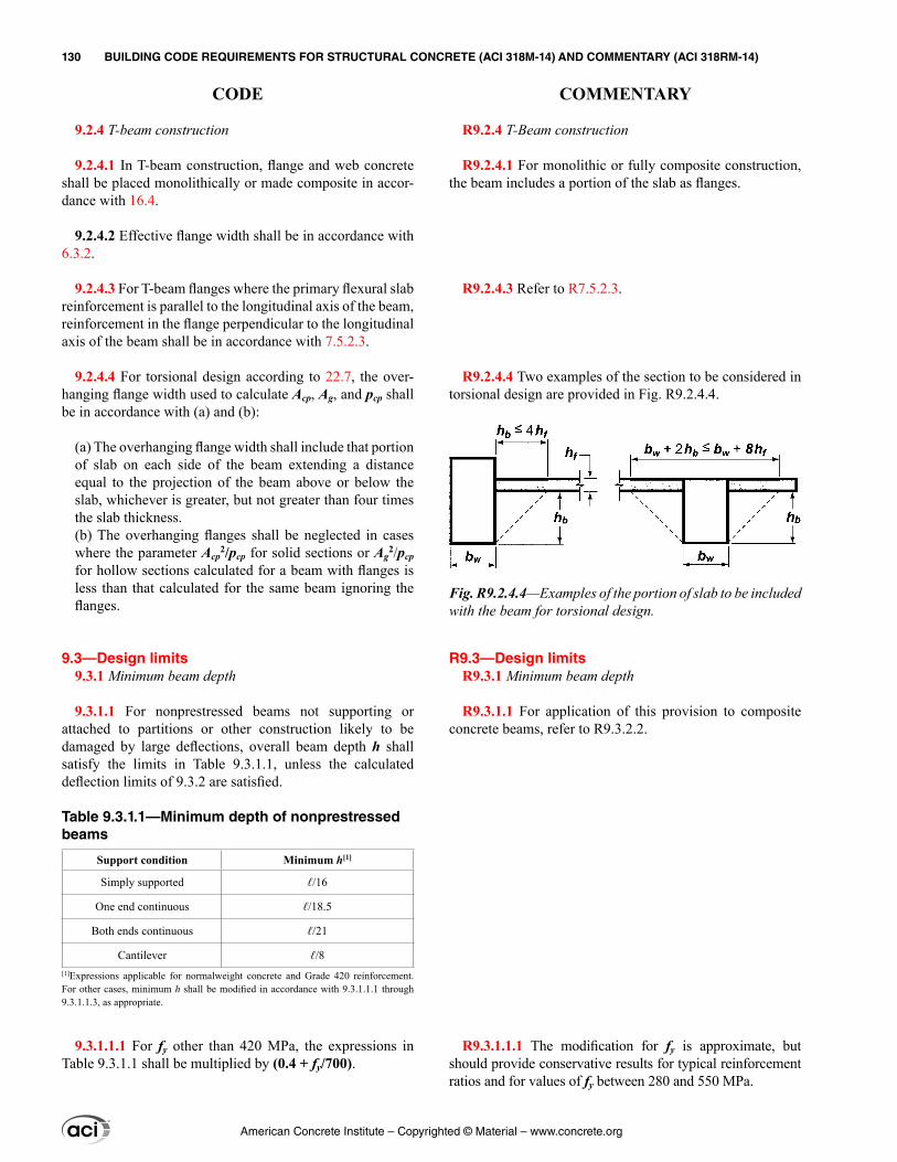
R9.2.4 T-Beam construction
R9.2.4.1 For monolithic or fully composite construction, the beam includes a portion of the slab as flanges.
R9.2.4.3 Refer to R7.5.2.3.
R9.2.4.4 Two examples of the section to be considered in torsional design are provided in Fig. R9.2.4.4.
R9.3—Design limits R9.3.1 Minimum beam depth
R9.3.1.1 For application of this provision to composite concrete beams, refer to R9.3.2.2.
R9.3.1.1.1 The modification for fy is approximate, but should provide conservative results for typical reinforcement ratios and for values of fy between 280 and 550 MPa.
9.2.4 T-beam construction
9.2.4.1 In T-beam construction, flange and web concrete shall be placed monolithically or made composite in accor-dance with 16.4.
9.2.4.2 Effective flange width shall be in accordance with 6.3.2.
9.2.4.3 For T-beam flanges where the primary flexural slab reinforcement is parallel to the longitudinal axis of the beam, reinforcement in the flange perpendicular to the longitudinal axis of the beam shall be in accordance with 7.5.2.3.
9.2.4.4 For torsional design according to 22.7, the over-hanging flange width used to calculate Acp, Ag, and pcp shall be in accordance with (a) and (b):
(a) The overhanging flange width shall include that portion of slab on each side of the beam extending a distance equal to the projection of the beam above or below the slab, whichever is greater, but not greater than four times the slab thickness.(b) The overhanging flanges shall be neglected in cases where the parameter Acp
2/pcp for solid sections or Ag2/pcp
for hollow sections calculated for a beam with flanges is less than that calculated for the same beam ignoring the flanges.
9.3—Design limits 9.3.1 Minimum beam depth
9.3.1.1 For nonprestressed beams not supporting or attached to partitions or other construction likely to be damaged by large deflections, overall beam depth h shall satisfy the limits in Table 9.3.1.1, unless the calculated deflection limits of 9.3.2 are satisfied.
Table 9.3.1.1—Minimum depth of nonprestressed beams
Support condition Minimum h[1]
Simply supported ℓ/16
One end continuous ℓ/18.5
Both ends continuous ℓ/21
Cantilever ℓ/8[1]Expressions applicable for normalweight concrete and Grade 420 reinforcement. For other cases, minimum h shall be modified in accordance with 9.3.1.1.1 through 9.3.1.1.3, as appropriate.
9.3.1.1.1 For fy other than 420 MPa, the expressions in Table 9.3.1.1 shall be multiplied by (0.4 + fy/700).
Fig. R9.2.4.4—Examples of the portion of slab to be included with the beam for torsional design.
American Concrete Institute – Copyrighted © Material – www.concrete.org
130 BUILDING CODE REQUIREMENTS FOR STRUCTURAL CONCRETE (ACI 318M-14) AND COMMENTARY (ACI 318RM-14)
CODE COMMENTARY
R9.3.1.1.2 The modification for lightweight concrete is based on the results and discussions in ACI 213R. No correction is given for concretes with wc greater than 1840 kg/m3 because the correction term would be close to unity in this range.
R9.3.2 Calculated deflection limits
R9.3.2.2 The limits in Table 9.3.1.1 apply to the entire depth of nonprestressed composite beams shored during construction so that, after removal of temporary supports, the dead load is resisted by the full composite section. In unshored construction, the beam depth of concern depends on if the deflection being considered occurs before or after the attainment of effective composite action.
Additional deflections due to excessive creep and shrinkage caused by premature loading should be consid-ered. This is especially important at early ages when the moisture content is high and the strength is low.
The transfer of horizontal shear by direct bond is impor-tant if excessive deflection from slippage is to be prevented. Shear keys provide a means of transferring shear but will not be engaged until slippage occurs.
R9.3.3 Reinforcement strain limit in nonprestressed beams
R9.3.3.1 The effect of this limitation is to restrict the rein-forcement ratio in nonprestressed beams to mitigate brittle flexural behavior in case of an overload. This limitation does not apply to prestressed beams.
9.3.1.1.2 For nonprestressed beams made of lightweight concrete having wc in the range of 1440 to 1840 kg/m3, the expressions in Table 9.3.1.1 shall be multiplied by the greater of (a) and (b):
(a) 1.65 – 0.0003wc(b) 1.09
9.3.1.1.3 For nonprestressed composite beams made of a combination of lightweight and normalweight concrete, shored during construction, and where the lightweight concrete is in compression, the modifier of 9.3.1.1.2 shall apply.
9.3.1.2 The thickness of a concrete floor finish shall be permitted to be included in h if it is placed monolithi-cally with the beam or if the floor finish is designed to be composite with the beam in accordance with 16.4.
9.3.2 Calculated deflection limits
9.3.2.1 For nonprestressed beams not satisfying 9.3.1 and for prestressed beams, immediate and time-dependent deflections shall be calculated in accordance with 24.2 and shall not exceed the limits in 24.2.2.
9.3.2.2 For nonprestressed composite concrete beams satisfying 9.3.1, deflections occurring after the member becomes composite need not be calculated. Deflections occurring before the member becomes composite shall be investigated unless the precomposite depth also satisfies 9.3.1.
9.3.3 Reinforcement strain limit in nonprestressed beams
9.3.3.1 For nonprestressed beams with Pu < 0.10fc′Ag, εt shall be at least 0.004.
9.3.4 Stress limits in prestressed beams
9.3.4.1 Prestressed beams shall be classified as Class U, T, or C in accordance with 24.5.2.
9.3.4.2 Stresses in prestressed beams immediately after transfer and at service loads shall not exceed permissible stresses in 24.5.3 and 24.5.4.
American Concrete Institute – Copyrighted © Material – www.concrete.org
CHAPTER 9—BEAMS 131
CODE COMMENTARY
9
R9.4—Required strength
R9.4.3 Factored shear
R9.4.3.2 The closest inclined crack to the support of the beam in Fig. R9.4.3.2a will extend upward from the face of the support reaching the compression zone approximately d from the face of the support. If loads are applied to the top of the beam, the stirrups across this crack need only resist the shear force due to loads acting beyond d (right free body in Fig. R9.4.3.2a). The loads applied to the beam between the face of the support and the point d away from the face are transferred directly to the support by compression in the web above the crack. Accordingly, the Code permits design for a maximum factored shear Vu at a distance d from the support for nonprestressed beams and at a distance h/2 for prestressed beams.
In Fig. R9.4.3.2b, loads are shown acting near the bottom of a beam. In this case, the critical section is taken at the face of the support. Loads acting near the support should be transferred across the inclined crack extending upward from the support face. The shear force acting on the critical section should include all loads applied below the potential inclined crack.
Typical support conditions where the shear force at a distance d from the support may be used include:
(a) Beams supported by bearing at the bottom of the beam, such as shown in Fig. R9.4.3.2(c)(b) Beams framing monolithically into a column, as illus-trated in Fig. R9.4.3.2(d)
Typical support conditions where the critical section is taken at the face of support include:
9.4—Required strength 9.4.1 General
9.4.1.1 Required strength shall be calculated in accor-dance with the factored load combinations in Chapter 5.
9.4.1.2 Required strength shall be calculated in accor-dance with the analysis procedures in Chapter 6.
9.4.1.3 For prestressed beams, effects of reactions induced by prestressing shall be considered in accordance with 5.3.11.
9.4.2 Factored moment
9.4.2.1 For beams built integrally with supports, Mu at the support shall be permitted to be calculated at the face of support.
9.4.3 Factored shear
9.4.3.1 For beams built integrally with supports, Vu at the support shall be permitted to be calculated at the face of support.
9.4.3.2 Sections between the face of support and a critical section located d from the face of support for nonprestressed beams and h/2 from the face of support for prestressed beams shall be permitted to be designed for Vu at that critical section if (a) through (c) are satisfied:
(a) Support reaction, in direction of applied shear, intro-duces compression into the end region of the beam(b) Loads are applied at or near the top surface of the beam(c) No concentrated load occurs between the face of support and critical section
American Concrete Institute – Copyrighted © Material – www.concrete.org
132 BUILDING CODE REQUIREMENTS FOR STRUCTURAL CONCRETE (ACI 318M-14) AND COMMENTARY (ACI 318RM-14)
CODE COMMENTARY
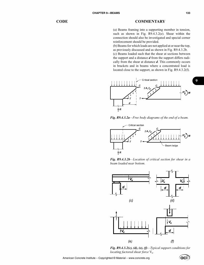
(a) Beams framing into a supporting member in tension, such as shown in Fig. R9.4.3.2(e). Shear within the connection should also be investigated and special corner reinforcement should be provided.(b) Beams for which loads are not applied at or near the top, as previously discussed and as shown in Fig. R9.4.3.2b.(c) Beams loaded such that the shear at sections between the support and a distance d from the support differs radi-cally from the shear at distance d. This commonly occurs in brackets and in beams where a concentrated load is located close to the support, as shown in Fig. R9.4.3.2(f).
Fig. R9.4.3.2a—Free body diagrams of the end of a beam.
Fig. R9.4.3.2b—Location of critical section for shear in a beam loaded near bottom.
Fig. R9.4.3.2(c), (d), (e), (f)—Typical support conditions for locating factored shear force Vu.
American Concrete Institute – Copyrighted © Material – www.concrete.org
CHAPTER 9—BEAMS 133
CODE COMMENTARY
9
9.4.4 Factored torsion
9.4.4.1 Unless determined by a more detailed analysis, it shall be permitted to take the torsional loading from a slab as uniformly distributed along the beam.
9.4.4.2 For beams built integrally with supports, Tu at the support shall be permitted to be calculated at the face of support.
9.4.4.3 Sections between the face of support and a critical section located d from the face of support for nonprestressed beams or h/2 from the face of support for prestressed beams shall be permitted to be designed for Tu at that critical section unless a concentrated torsional moment occurs within this distance. In that case, the critical section shall be taken at the face of the support.
9.4.4.4 It shall be permitted to reduce Tu in accordance with 22.7.3.
9.5—Design strength 9.5.1 General
9.5.1.1 For each applicable factored load combination, design strength at all sections shall satisfy ϕSn ≥ U including (a) through (d). Interaction between load effects shall be considered.
(a) ϕMn ≥ Mu(b) ϕVn ≥ Vu(c) ϕTn ≥ Tu(d) ϕPn ≥ Pu
9.5.1.2 ϕ shall be determined in accordance with 21.2.
9.5.2 Moment
9.5.2.1 If Pu < 0.10fc′Ag, Mn shall be calculated in accor-dance with 22.3.
9.5.2.2 If Pu ≥ 0.10fc′Ag, Mn shall be calculated in accor-dance with 22.4.
9.5.2.3 For prestressed beams, external tendons shall be considered as unbonded tendons in calculating flexural strength, unless the external tendons are effectively bonded to the concrete along the entire length.
R9.4.4 Factored torsion
R9.4.4.3 It is not uncommon for a beam to frame into one side of a girder near the support of the girder. In such a case, a concentrated shear and torque are applied to the girder.
R9.5—Design strength R9.5.1 General
R9.5.1.1 The design conditions 9.5.1.1(a) through (d) list the typical forces and moments that need to be considered. However, the general condition ϕSn ≥ U indicates that all forces and moments that are relevant for a given structure need to be considered.
R9.5.2 Moment
R9.5.2.2 Beams resisting significant axial forces require consideration of the combined effects of axial forces and moments. These beams are not required to satisfy the provi-sions of Chapter 10, but are required to satisfy the additional requirements for ties or spirals defined in Table 22.4.2.1. For slender beams with significant axial loads, consider-ation should be given to slenderness effects as required for columns in 6.2.6.
American Concrete Institute – Copyrighted © Material – www.concrete.org
134 BUILDING CODE REQUIREMENTS FOR STRUCTURAL CONCRETE (ACI 318M-14) AND COMMENTARY (ACI 318RM-14)
CODE COMMENTARY
9.5.3 Shear
9.5.3.1 Vn shall be calculated in accordance with 22.5.
9.5.3.2 For composite concrete beams, horizontal shear strength Vnh shall be calculated in accordance with 16.4.
9.5.4 Torsion
9.5.4.1 If Tu < ϕTth, where Tth is given in 22.7, it shall be permitted to neglect torsional effects. The minimum rein-forcement requirements of 9.6.4 and the detailing require-ments of 9.7.5 and 9.7.6.3 need not be satisfied.
9.5.4.2 Tn shall be calculated in accordance with 22.7.
9.5.4.3 Longitudinal and transverse reinforcement required for torsion shall be added to that required for the Vu, Mu, and Pu that act in combination with the torsion.
9.5.4.4 For prestressed beams, the total area of longitu-dinal reinforcement, As and Aps, at each section shall be designed to resist Mu at that section, plus an additional concentric longitudinal tensile force equal to Aℓfy, based on Tu at that section.
R9.5.4 Torsion
R9.5.4.3 The requirements for torsional reinforcement and shear reinforcement are added and stirrups are provided to supply at least the total amount required. Because the reinforcement area Av for shear is defined in terms of all the legs of a given stirrup while the reinforcement area At for torsion is defined in terms of one leg only, the addition of transverse reinforcement area is calculated as follows:
Total 2v t v tA A As s s
+ = + (R9.5.4.3)
If a stirrup group has more than two legs for shear, only the legs adjacent to the sides of the beam are included in this summation because the inner legs would be ineffective for resisting torsion.
The longitudinal reinforcement required for torsion is added at each section to the longitudinal reinforcement required for bending moment that acts concurrently with the torsion. The longitudinal reinforcement is then chosen for this sum, but should not be less than the amount required for the maximum bending moment at that section if this exceeds the moment acting concurrently with the torsion. If the maximum bending moment occurs at one section, such as midspan, while the maximum torsional moment occurs at another, such as the face of the support, the total longitu-dinal reinforcement required may be less than that obtained by adding the maximum flexural reinforcement, plus the maximum torsional reinforcement. In such a case, the required longitudinal reinforcement is evaluated at several locations.
R9.5.4.4 Torsion causes an axial tensile force in the longi-tudinal reinforcement balanced by the force in the diagonal concrete compression struts. In a nonprestressed beam, the tensile force must be resisted by longitudinal reinforcement having an axial tensile strength of Aℓ fy. This reinforcement is in addition to the required flexural reinforcement and is distributed uniformly inside and around the perimeter of the closed transverse reinforcement so that the resultant of Aℓfy acts along the axis of the member.
American Concrete Institute – Copyrighted © Material – www.concrete.org
CHAPTER 9—BEAMS 135
CODE COMMENTARY
9
9.5.4.5 It shall be permitted to reduce the area of longi-tudinal torsional reinforcement in the flexural compression zone by an amount equal to Mu/(0.9dfy), where Mu occurs simultaneously with Tu at that section, except that the longitudinal reinforcement area shall not be less than the minimum required in 9.6.4.
9.5.4.6 For solid sections with an aspect ratio h/bt ≥ 3, it shall be permitted to use an alternative design procedure, provided the adequacy of the procedure has been shown by analysis and substantial agreement with results of compre-hensive tests. The minimum reinforcement requirements of 9.6.4 need not be satisfied, but the detailing requirements of 9.7.5 and 9.7.6.3 apply.
9.5.4.7 For solid precast sections with an aspect ratio h/bt ≥ 4.5, it shall be permitted to use an alternative design proce-dure and open web reinforcement, provided the adequacy of the procedure and reinforcement have been shown by analysis and substantial agreement with results of compre-hensive tests. The minimum reinforcement requirements of 9.6.4 and detailing requirements of 9.7.5 and 9.7.6.3 need not be satisfied.
9.6—Reinforcement limits 9.6.1 Minimum flexural reinforcement in nonprestressed
beams
9.6.1.1 A minimum area of flexural reinforcement, As,min, shall be provided at every section where tension reinforce-ment is required by analysis.
In a prestressed beam, the same approach (providing addi-tional reinforcing bars with strength Aℓfy) may be followed, or overstrength of the prestressed reinforcement can be used to resist some of the axial force Aℓfy. The stress in the prestressed reinforcement at nominal strength will be between fse and fps. A portion of the Aℓfy force can be resisted by a force of Aps∆fpt in the prestressed reinforcement, where ∆fpt is the difference between the stress that can be devel-oped in the strand at the section under consideration and the stress required to resist the bending moment at this section, Mu. The stress required to resist the bending moment can be calculated as Mu/(ϕ0.9dpAps). For pretensioned strands, the stress that can be developed near the free end of the strand can be calculated using the procedure illustrated in Fig. R25.4.8.3.
R9.5.4.5 The longitudinal tension due to torsion is offset in part by the compression in the flexural compression zone, allowing a reduction in the longitudinal torsional reinforce-ment required in the compression zone.
R9.5.4.6 An example of an alternative design that satisfies this provision can be found in Zia and Hsu (2004), which has been extensively and successfully used for design of precast, prestressed concrete spandrel beams with h/bt ≥ 3 and closed stirrups. The seventh edition of the PCI Design Handbook (PCI MNL-120) describes the procedure of Zia and Hsu (2004). This procedure was experimentally verified by the tests described in Klein (1986).
R9.5.4.7 The experimental results described in Lucier et al. (2011a) demonstrate that properly designed open web reinforcement is a safe and effective alternative to traditional closed stirrups for precast spandrels with h/bt ≥ 4.5. Lucier et al. (2011b) presents a design procedure that satisfies this provision for slender spandrels and describes the limited conditions to which the procedure applies.
R9.6—Reinforcement limits R9.6.1 Minimum flexural reinforcement in nonprestressed
beams
R9.6.1.1 This provision is intended to result in flexural strength exceeding the cracking strength by a margin. The objective is to produce a beam that will be able to sustain loading after the onset of flexural cracking, with visible cracking and deflection, thereby warning of possible over-load. Beams with less reinforcement may sustain sudden failure with the onset of flexural cracking.
In practice, this provision only controls reinforcement design for beams which, for architectural or other reasons, are larger in cross section than required for strength. With a small amount of tension reinforcement required for strength,
American Concrete Institute – Copyrighted © Material – www.concrete.org
136 BUILDING CODE REQUIREMENTS FOR STRUCTURAL CONCRETE (ACI 318M-14) AND COMMENTARY (ACI 318RM-14)
CODE COMMENTARY
9.6.1.2 As,min shall be the greater of (a) and (b), except as provided in 9.6.1.3. For a statically determinate beam with a flange in tension, the value of bw shall be the lesser of bf and 2bw.
(a) 0.25 ′c
wy
fb d
f
(b) 1.4w
y
b df
9.6.1.3 If As provided at every section is at least one-third greater than As required by analysis, 9.6.1.1 and 9.6.1.2 need not be satisfied.
9.6.2 Minimum flexural reinforcement in prestressed beams
9.6.2.1 For beams with bonded prestressed reinforcement, total quantity of As and Aps shall be adequate to develop a factored load at least 1.2 times the cracking load calculated on the basis of fr defined in 19.2.3.
9.6.2.2 For beams with both flexural and shear design strength at least twice the required strength, 9.6.2.1 need not be satisfied.
9.6.2.3 For beams with unbonded tendons, the minimum area of bonded deformed longitudinal reinforcement As,min shall be:
As,min = 0.004Act (9.6.2.3)
where Act is the area of that part of the cross section between the flexural tension face and the centroid of the gross section.
the calculated moment strength of a reinforced concrete section using cracked section analysis becomes less than that of the corresponding unreinforced concrete section calculated from its modulus of rupture. Failure in such a case could occur at first cracking and without warning. To prevent such a failure, a minimum amount of tension reinforcement is required in both positive and negative moment regions.
R9.6.1.2 If the flange of a section is in tension, the amount of tension reinforcement needed to make the strength of the reinforced section equal that of the unreinforced section is approximately twice that for a rectangular section or that of a flanged section with the flange in compression. A greater amount of minimum tension reinforcement is particularly necessary in cantilevers and other statically determinate beams where there is no possibility for redistribution of moments.
R9.6.2 Minimum flexural reinforcement in prestressed beams
R9.6.2.1 Minimum flexural reinforcement is required for reasons similar to nonprestressed beams as discussed in R9.6.1.1.
Abrupt flexural failure immediately after cracking does not occur when the prestressing reinforcement is unbonded (ACI 423.3R); therefore, this requirement does not apply to members with unbonded tendons.
R9.6.2.3 Minimum bonded reinforcement is required by the Code in beams prestressed with unbonded tendons to ensure flexural behavior at ultimate beam strength, rather than tied arch behavior, and to limit crack width and spacing at service load when concrete tensile stresses exceed the modulus of rupture. Providing minimum bonded reinforce-ment helps to ensure acceptable behavior at all loading stages. The minimum amount of bonded reinforcement is based on research comparing the behavior of bonded and unbonded post-tensioned beams (Mattock et al. 1971). The minimum bonded reinforcement area required by Eq. (9.6.2.3) is independent of reinforcement fy.
American Concrete Institute – Copyrighted © Material – www.concrete.org
CHAPTER 9—BEAMS 137
CODE COMMENTARY
9
9.6.3 Minimum shear reinforcement
9.6.3.1 A minimum area of shear reinforcement, Av,min, shall be provided in all regions where Vu > 0.5ϕVc except for the cases in Table 9.6.3.1. For these cases, at least Av,min shall be provided where Vu > ϕVc.
Table 9.6.3.1—Cases where Av,min is not required if 0.5ϕVc < Vu ≤ ϕVc
Beam type ConditionsShallow depth h ≤ 250 mm
Integral with slabh ≤ greater of 2.5tf or 0.5bw
andh ≤ 600 mm
Constructed with steel fiber-reinforced normalweight concrete conforming to 26.4.1.5.1(a), 26.4.2.2(d), and 26.12.5.1(a) and with fc′ ≤ 40 MPa
h ≤ 600 mmand
0.17≤ φ ′u c wV f b d
One-way joist system In accordance with 9.8
R9.6.3 Minimum shear reinforcement
R9.6.3.1 Shear reinforcement restrains the growth of inclined cracking so that ductility of the beam is improved and a warning of failure is provided. In an unreinforced web, the formation of inclined cracking might lead directly to failure without warning. Such reinforcement is of great value if a beam is subjected to an unexpected tensile force or an overload. Accordingly, a minimum area of shear reinforcement not less than that given by Table 9.6.3.3 is required wherever Vu is greater than 0.5ϕVc, or greater than ϕVc for the cases indicated in Table 9.6.3.1.
Research (Angelakos et al. 2001; Lubell et al. 2004; Brown et al. 2006; Becker and Buettner 1985; Anderson 1978) has shown that deep, lightly reinforced beams, particularly if constructed with high-strength concrete or concrete having a small coarse aggregate size, may fail at shears less than Vc calculated from 22.5.5. Beams subjected to concentrated loads are more likely to exhibit this vulnerability. Because of this, the exclusion for certain beam types in Table 9.6.3.1 is restricted to cases in which h does not exceed 600 mm. For beams where fc′ is greater than 48 MPa, consideration should be given to providing minimum shear reinforcement if h is greater than 450 mm and Vu is greater than 0.5ϕVc.
The exception for beams constructed using steel fiber-rein-forced concrete is intended to provide a design alternative to the use of shear reinforcement, as defined in 22.5.10.5, for beams with longitudinal flexural reinforcement in which Vu does not exceed ′0.17φ c wf b d . Chapter 26 specifies design information and compliance requirements that need to be incorporated into the construction documents when steel fiber-reinforced concrete is used for this purpose. Fiber-reinforced concrete beams with hooked or crimped steel fibers, in dosages as required by 26.4.2.2(d), have been shown through laboratory tests to exhibit shear strengths greater than ′0.29 c wf b d (Parra-Montesinos 2006). There are no data for the use of steel fibers as shear reinforcement in concrete beams exposed to chlorides from deicing chemi-cals, salt, salt water, brackish water, seawater, or spray from these sources. Where steel fibers are used as shear reinforce-ment in corrosive environments, corrosion protection should be considered.
Joists are excluded from the minimum shear reinforce-ment requirement for 0.5ϕVc < Vu ≤ ϕVc because there is a possibility of load sharing between weak and strong areas.
Even when Vu is less than 0.5ϕVc, the use of some web reinforcement is recommended in all thin-web, post-tensioned members such as joists, waffle slabs, beams, and T-beams, to reinforce against tensile forces in webs resulting from local deviations from the design tendon profile and to provide a means of supporting the tendons in the design profile during construction. If sufficient support is not provided, lateral wobble and local deviations from the smooth parabolic tendon profile assumed in design may result during placement of the concrete. In such cases, the deviations in the tendons tend to straighten out when the
American Concrete Institute – Copyrighted © Material – www.concrete.org
138 BUILDING CODE REQUIREMENTS FOR STRUCTURAL CONCRETE (ACI 318M-14) AND COMMENTARY (ACI 318RM-14)
CODE COMMENTARY
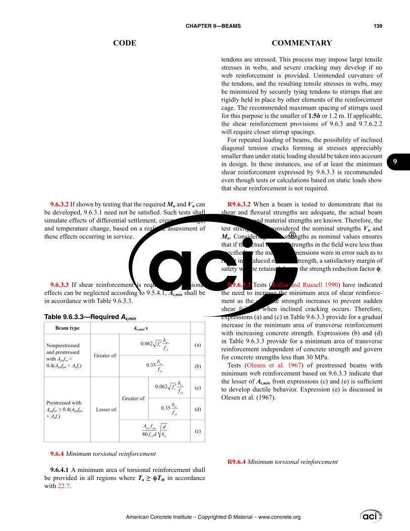
tendons are stressed. This process may impose large tensile stresses in webs, and severe cracking may develop if no web reinforcement is provided. Unintended curvature of the tendons, and the resulting tensile stresses in webs, may be minimized by securely tying tendons to stirrups that are rigidly held in place by other elements of the reinforcement cage. The recommended maximum spacing of stirrups used for this purpose is the smaller of 1.5h or 1.2 m. If applicable, the shear reinforcement provisions of 9.6.3 and 9.7.6.2.2 will require closer stirrup spacings.
For repeated loading of beams, the possibility of inclined diagonal tension cracks forming at stresses appreciably smaller than under static loading should be taken into account in design. In these instances, use of at least the minimum shear reinforcement expressed by 9.6.3.3 is recommended even though tests or calculations based on static loads show that shear reinforcement is not required.
R9.6.3.2 When a beam is tested to demonstrate that its shear and flexural strengths are adequate, the actual beam dimensions and material strengths are known. Therefore, the test strengths are considered the nominal strengths Vn and Mn. Considering these strengths as nominal values ensures that if the actual material strengths in the field were less than specified, or the member dimensions were in error such as to result in a reduced member strength, a satisfactory margin of safety will be retained due to the strength reduction factor ϕ.
R9.6.3.3 Tests (Roller and Russell 1990) have indicated the need to increase the minimum area of shear reinforce-ment as the concrete strength increases to prevent sudden shear failures when inclined cracking occurs. Therefore, expressions (a) and (c) in Table 9.6.3.3 provide for a gradual increase in the minimum area of transverse reinforcement with increasing concrete strength. Expressions (b) and (d) in Table 9.6.3.3 provide for a minimum area of transverse reinforcement independent of concrete strength and govern for concrete strengths less than 30 MPa.
Tests (Olesen et al. 1967) of prestressed beams with minimum web reinforcement based on 9.6.3.3 indicate that the lesser of Av,min from expressions (c) and (e) is sufficient to develop ductile behavior. Expression (e) is discussed in Olesen et al. (1967).
R9.6.4 Minimum torsional reinforcement
9.6.3.2 If shown by testing that the required Mn and Vn can be developed, 9.6.3.1 need not be satisfied. Such tests shall simulate effects of differential settlement, creep, shrinkage, and temperature change, based on a realistic assessment of these effects occurring in service.
9.6.3.3 If shear reinforcement is required and torsional effects can be neglected according to 9.5.4.1, Av,min shall be in accordance with Table 9.6.3.3.
Table 9.6.3.3—Required Av,min
Beam type Av,min/s
Nonprestressedand prestressed with Apsfse < 0.4(Apsfpu + Asfy)
Greater of:
0.062 ′ wc
yt
bff (a)
0.35 w
yt
bf (b)
Prestressed with Apsfse ≥ 0.4(Apsfpu + Asfy)
Lesser of:
Greater of:
0.062 ′ wc
yt
bff (c)
0.35 w
yt
bf (d)
80ps pu
yt w
A f df d b (e)
9.6.4 Minimum torsional reinforcement
9.6.4.1 A minimum area of torsional reinforcement shall be provided in all regions where Tu ≥ ϕTth in accordance with 22.7.
American Concrete Institute – Copyrighted © Material – www.concrete.org
CHAPTER 9—BEAMS 139
CODE COMMENTARY
9
R9.6.4.2 The differences in the definitions of Av and At should be noted: Av is the area of two legs of a closed stirrup, whereas At is the area of only one leg of a closed stirrup. If a stirrup group has more than two legs, only the legs adja-cent to the sides of the beam are considered, as discussed in R9.5.4.3.
Tests (Roller and Russell 1990) of high-strength rein-forced concrete beams have indicated the need to increase the minimum area of shear reinforcement to prevent shear failures when inclined cracking occurs. Although there are a limited number of tests of high-strength concrete beams in torsion, the equation for the minimum area of transverse closed stirrups has been made consistent with calculations required for minimum shear reinforcement.
R9.6.4.3 Under combined torsion and shear, the torsional cracking moment decreases with applied shear, which leads to a reduction in torsional reinforcement required to prevent brittle failure immediately after cracking. When subjected to pure torsion, reinforced concrete beam specimens with less than 1 percent torsional reinforcement by volume have failed at first torsional cracking (MacGregor and Ghoneim 1995). Equation 9.6.4.3(a) is based on a 2:1 ratio of torsion stress to shear stress and results in a torsional reinforce-ment volumetric ratio of approximately 0.5 percent (Hsu 1968). Tests of prestressed concrete beams have shown that a similar amount of longitudinal reinforcement is required.
R9.7—Reinforcement detailing
R9.7.2 Reinforcement spacing
R9.7.2.3 For relatively deep beams, some reinforcement should be placed near the vertical faces of the tension zone to control cracking in the web (Frantz and Breen 1980; Frosch 2002), as shown in Fig. R9.7.2.3. Without such auxil-iary reinforcement, the width of the cracks in the web may
9.6.4.2 If torsional reinforcement is required, minimum transverse reinforcement (Av + 2At)min/s shall be the greater of (a) and (b):
(a) 0.062 ′ wc
yt
bf
f
(b) 0.35 w
yt
bf
9.6.4.3 If torsional reinforcement is required, minimum area of longitudinal reinforcement Aℓ,min shall be the lesser of (a) and (b):
(a) 0.42 −′ cp ytt
c hyt y
A fAf p
f s f
(b) 0.175
0.42
−′
cp ytwc h
yt yt y
A fbf p
f f f
9.7—Reinforcement detailing 9.7.1 General
9.7.1.1 Concrete cover for reinforcement shall be in accor-dance with 20.6.1.
9.7.1.2 Development lengths of deformed and prestressed reinforcement shall be in accordance with 25.4.
9.7.1.3 Splices of deformed reinforcement shall be in accordance with 25.5.
9.7.1.4 Bundled bars shall be in accordance with 25.6.
9.7.2 Reinforcement spacing
9.7.2.1 Minimum spacing s shall be in accordance with 25.2.
9.7.2.2 For nonprestressed and Class C prestressed beams, spacing of bonded longitudinal reinforcement closest to the tension face shall not exceed s given in 24.3.
9.7.2.3 For nonprestressed and Class C prestressed beams with h exceeding 900 mm, longitudinal skin reinforcement shall be uniformly distributed on both side faces of the beam for a distance h/2 from the tension face. Spacing of skin rein-forcement shall not exceed s given in 24.3.2, where cc is the
American Concrete Institute – Copyrighted © Material – www.concrete.org
140 BUILDING CODE REQUIREMENTS FOR STRUCTURAL CONCRETE (ACI 318M-14) AND COMMENTARY (ACI 318RM-14)
CODE COMMENTARY
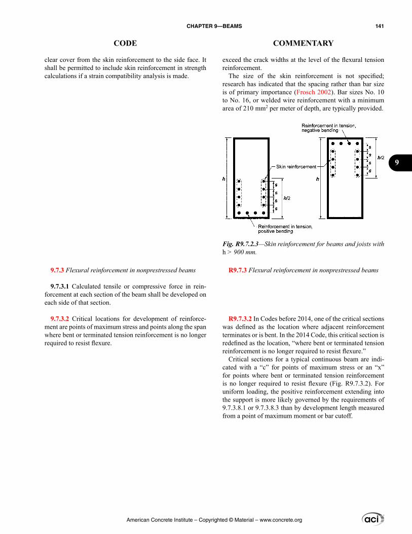
exceed the crack widths at the level of the flexural tension reinforcement.
The size of the skin reinforcement is not specified; research has indicated that the spacing rather than bar size is of primary importance (Frosch 2002). Bar sizes No. 10 to No. 16, or welded wire reinforcement with a minimum area of 210 mm2 per meter of depth, are typically provided.
R9.7.3 Flexural reinforcement in nonprestressed beams
R9.7.3.2 In Codes before 2014, one of the critical sections was defined as the location where adjacent reinforcement terminates or is bent. In the 2014 Code, this critical section is redefined as the location, “where bent or terminated tension reinforcement is no longer required to resist flexure.”
Critical sections for a typical continuous beam are indi-cated with a “c” for points of maximum stress or an “x” for points where bent or terminated tension reinforcement is no longer required to resist flexure (Fig. R9.7.3.2). For uniform loading, the positive reinforcement extending into the support is more likely governed by the requirements of 9.7.3.8.1 or 9.7.3.8.3 than by development length measured from a point of maximum moment or bar cutoff.
clear cover from the skin reinforcement to the side face. It shall be permitted to include skin reinforcement in strength calculations if a strain compatibility analysis is made.
9.7.3 Flexural reinforcement in nonprestressed beams
9.7.3.1 Calculated tensile or compressive force in rein-forcement at each section of the beam shall be developed on each side of that section.
9.7.3.2 Critical locations for development of reinforce-ment are points of maximum stress and points along the span where bent or terminated tension reinforcement is no longer required to resist flexure.
Fig. R9.7.2.3—Skin reinforcement for beams and joists with h > 900 mm.
American Concrete Institute – Copyrighted © Material – www.concrete.org
CHAPTER 9—BEAMS 141
CODE COMMENTARY
9
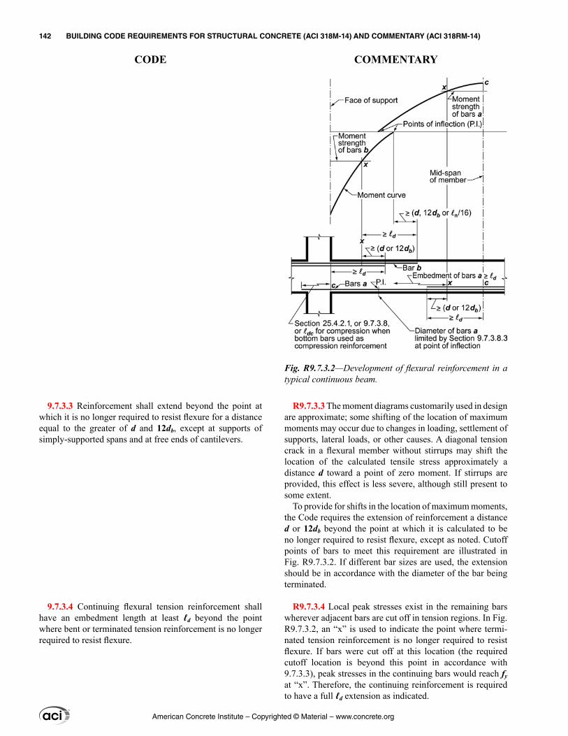
R9.7.3.3 The moment diagrams customarily used in design are approximate; some shifting of the location of maximum moments may occur due to changes in loading, settlement of supports, lateral loads, or other causes. A diagonal tension crack in a flexural member without stirrups may shift the location of the calculated tensile stress approximately a distance d toward a point of zero moment. If stirrups are provided, this effect is less severe, although still present to some extent.
To provide for shifts in the location of maximum moments, the Code requires the extension of reinforcement a distance d or 12db beyond the point at which it is calculated to be no longer required to resist flexure, except as noted. Cutoff points of bars to meet this requirement are illustrated in Fig. R9.7.3.2. If different bar sizes are used, the extension should be in accordance with the diameter of the bar being terminated.
R9.7.3.4 Local peak stresses exist in the remaining bars wherever adjacent bars are cut off in tension regions. In Fig. R9.7.3.2, an “x” is used to indicate the point where termi-nated tension reinforcement is no longer required to resist flexure. If bars were cut off at this location (the required cutoff location is beyond this point in accordance with 9.7.3.3), peak stresses in the continuing bars would reach fy at “x”. Therefore, the continuing reinforcement is required to have a full ℓd extension as indicated.
9.7.3.3 Reinforcement shall extend beyond the point at which it is no longer required to resist flexure for a distance equal to the greater of d and 12db, except at supports of simply-supported spans and at free ends of cantilevers.
9.7.3.4 Continuing flexural tension reinforcement shall have an embedment length at least ℓd beyond the point where bent or terminated tension reinforcement is no longer required to resist flexure.
Fig. R9.7.3.2—Development of flexural reinforcement in a typical continuous beam.
American Concrete Institute – Copyrighted © Material – www.concrete.org
142 BUILDING CODE REQUIREMENTS FOR STRUCTURAL CONCRETE (ACI 318M-14) AND COMMENTARY (ACI 318RM-14)
CODE COMMENTARY
R9.7.3.5 Reduced shear strength and loss of ductility when bars are cut off in a tension zone, as in Fig. R9.7.3.2, have been reported. The Code does not permit flexural reinforce-ment to be terminated in a tension zone unless additional conditions are satisfied. Flexural cracks tend to open at low load levels wherever any reinforcement is terminated in a tension zone. If the stress in the continuing reinforcement and the shear strength are each near their limiting values, diagonal tension cracking tends to develop prematurely from these flexural cracks. Diagonal cracks are less likely to form where shear stress is low (9.7.3.5(a)) or flexural reinforcement stress is low (9.7.3.5(b)). Diagonal cracks can be restrained by closely spaced stirrups (9.7.3.5(c)). These requirements are not intended to apply to tension splices that are covered by 25.5.
R9.7.3.7 A bar bent to the far face of a beam and continued there may be considered effective in satisfying 9.7.3.3 to the point where the bar crosses the mid-depth of the member.
R9.7.3.8 Termination of reinforcement
R9.7.3.8.1 Positive moment reinforcement is extended into the support to provide for some shifting of the moments due to changes in loading, settlement of supports, and lateral loads. It also enhances structural integrity.
For precast beams, tolerances and reinforcement cover should be considered to avoid bearing on plain concrete where reinforcement has been discontinued.
R9.7.3.8.2 Development of the positive moment reinforce-ment at the support is required for beams that are part of the primary lateral-load-resisting system to provide ductility in the event of moment reversal.
R9.7.3.8.3 The diameter of the positive moment tension reinforcement is limited to ensure that the bars are devel-oped in a length short enough such that the moment capacity is greater than the applied moment over the entire length of the beam. As illustrated in the moment diagram of Fig. R9.7.3.8.3(a), the slope of the moment diagram is Vu, while the slope of moment development is Mn/ℓd, where Mn is the nominal flexural strength of the cross section. By sizing the reinforcement such that the capacity slope Mn/ℓd equals or exceeds the demand slope Vu, proper development is provided. Therefore, Mn/Vu represents the available devel-opment length. Under favorable support conditions, a 30 percent increase for Mn/Vu is permitted when the ends of the reinforcement are confined by a compressive reaction.
9.7.3.5 Flexural tension reinforcement shall not be termi-nated in a tension zone unless (a), (b), or (c) is satisfied:
(a) Vu ≤ (2/3)ϕVn at the cutoff point(b) For No. 36 bars and smaller, continuing reinforcement provides double the area required for flexure at the cutoff point and Vu ≤ (3/4)ϕVn(c) Stirrup or hoop area in excess of that required for shear and torsion is provided along each terminated bar or wire over a distance 3/4d from the termination point. Excess stirrup or hoop area shall be at least 0.41bws/fyt. Spacing s shall not exceed d/(8βb)
9.7.3.6 Adequate anchorage shall be provided for tension reinforcement where reinforcement stress is not directly proportional to moment, such as in sloped, stepped, or tapered beams, or where tension reinforcement is not parallel to the compression face.
9.7.3.7 Development of tension reinforcement by bending across the web to be anchored or made continuous with rein-forcement on the opposite face of beam shall be permitted.
9.7.3.8 Termination of reinforcement
9.7.3.8.1 At simple supports, at least one-third of the maximum positive moment reinforcement shall extend along the beam bottom into the support at least 150 mm, except for precast beams where such reinforcement shall extend at least to the center of the bearing length.
9.7.3.8.2 At other supports, at least one-fourth of the maximum positive moment reinforcement shall extend along the beam bottom into the support at least 150 mm and, if the beam is part of the primary lateral-load-resisting system, shall be anchored to develop fy at the face of the support.
9.7.3.8.3 At simple supports and points of inflection, db for positive moment tension reinforcement shall be limited such that ℓ for that reinforcement satisfies (a) or (b). If rein-forcement terminates beyond the centerline of supports by a standard hook or a mechanical anchorage at least equivalent to a standard hook, (a) or (b) need not be satisfied.
(a) ℓd ≤ (1.3Mn/Vu + ℓa) if end of reinforcement is confined by a compressive reaction(b) ℓd ≤ (Mn/Vu + ℓa) if end of reinforcement is not confined by a compressive reaction
Mn is calculated assuming all reinforcement at the section is stressed to fy, and Vu is calculated at the section. At a
American Concrete Institute – Copyrighted © Material – www.concrete.org
CHAPTER 9—BEAMS 143
CODE COMMENTARY
9
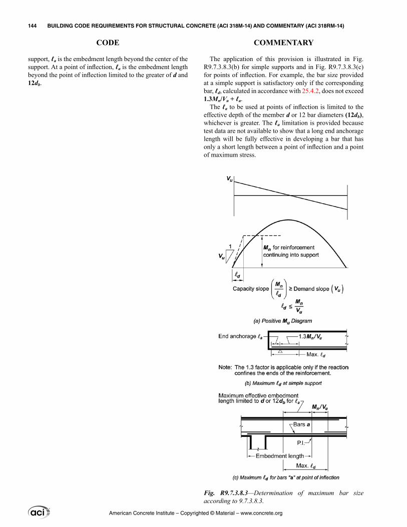
The application of this provision is illustrated in Fig. R9.7.3.8.3(b) for simple supports and in Fig. R9.7.3.8.3(c) for points of inflection. For example, the bar size provided at a simple support is satisfactory only if the corresponding bar, ℓd, calculated in accordance with 25.4.2, does not exceed 1.3Mn/Vu + ℓa.
The ℓa to be used at points of inflection is limited to the effective depth of the member d or 12 bar diameters (12db), whichever is greater. The ℓa limitation is provided because test data are not available to show that a long end anchorage length will be fully effective in developing a bar that has only a short length between a point of inflection and a point of maximum stress.
support, ℓa is the embedment length beyond the center of the support. At a point of inflection, ℓa is the embedment length beyond the point of inflection limited to the greater of d and 12db.
Fig. R9.7.3.8.3—Determination of maximum bar size according to 9.7.3.8.3.
American Concrete Institute – Copyrighted © Material – www.concrete.org
144 BUILDING CODE REQUIREMENTS FOR STRUCTURAL CONCRETE (ACI 318M-14) AND COMMENTARY (ACI 318RM-14)
CODE COMMENTARY
R9.7.4 Flexural reinforcement in prestressed beams
R9.7.4.1 External tendons are often attached to the concrete beam at various locations between anchorages, such as midspan, quarter points, or third points, for desired load balancing effects, for tendon alignment, or to address tendon vibration concerns. Consideration should be given to the effects caused by the tendon profile shifting in relation-ship to the concrete centroid as the member deforms under effects of post-tensioning and applied load.
R9.7.4.2 Nonprestressed reinforcement should be devel-oped to achieve factored load forces. The requirements of 9.7.3 provide that bonded reinforcement required for flex-ural strength under factored loads is developed to achieve tensile or compressive forces.
R9.7.4.4 Termination of deformed reinforcement in beams with unbonded tendons
R9.7.4.4.1 The minimum lengths apply for bonded rein-forcement required by 9.6.2.3. Research (Odello and Mehta 1967) on continuous spans shows that these minimum lengths provide satisfactory behavior under service load and factored load conditions.
R9.7.5 Longitudinal torsional reinforcement
R9.7.5.1 Longitudinal reinforcement is needed to resist the sum of the longitudinal tensile forces due to torsion. Because the force acts along the centroidal axis of the section, the centroid of the additional longitudinal reinforcement for torsion should approximately coincide with the centroid of the section. The Code accomplishes this by requiring the longitudinal torsional reinforcement be distributed around the perimeter of the closed stirrups. Longitudinal bars or tendons are required in each corner of the stirrups to provide anchorage for the stirrup legs. Corner bars have also been found to be effective in developing torsional strength and controlling cracks.
9.7.3.8.4 At least one-third of the negative moment rein-forcement at a support shall have an embedment length beyond the point of inflection at least the greatest of d, 12db, and ℓn/16.
9.7.4 Flexural reinforcement in prestressed beams
9.7.4.1 External tendons shall be attached to the member in a manner that maintains the specified eccentricity between the tendons and the concrete centroid through the full range of anticipated member deflections.
9.7.4.2 If nonprestressed reinforcement is required to satisfy flexural strength, the detailing requirements of 9.7.3 shall be satisfied.
9.7.4.3 Termination of prestressed reinforcement
9.7.4.3.1 Post-tensioned anchorage zones shall be designed and detailed in accordance with 25.9.
9.7.4.3.2 Post-tensioning anchorages and couplers shall be designed and detailed in accordance with 25.8.
9.7.4.4 Termination of deformed reinforcement in beams with unbonded tendons
9.7.4.4.1 Length of deformed reinforcement required by 9.6.2.3 shall be in accordance with (a) and (b):
(a) At least ℓn/3 in positive moment areas and be centered in those areas(b) At least ℓn/6 on each side of the face of support in negative moment areas
9.7.5 Longitudinal torsional reinforcement
9.7.5.1 If torsional reinforcement is required, longitu-dinal torsional reinforcement shall be distributed around the perimeter of closed stirrups that satisfy 25.7.1.6 or hoops with a spacing not greater than 300 mm. The longitudinal reinforcement shall be inside the stirrup or hoop, and at least one longitudinal bar or tendon shall be placed in each corner.
American Concrete Institute – Copyrighted © Material – www.concrete.org
CHAPTER 9—BEAMS 145
CODE COMMENTARY
9
R9.7.5.3 The distance (bt + d) beyond the point at which longitudinal torsional reinforcement is calculated to be no longer required is greater than that used for shear and flex-ural reinforcement because torsional diagonal tension cracks develop in a helical form. The same distance is required by 9.7.6.3.2 for transverse torsional reinforcement.
R9.7.5.4 Longitudinal torsional reinforcement required at a support should be adequately anchored into the support. Sufficient embedment length should be provided outside the inner face of the support to develop the needed tensile force in the bars or tendons. For bars, this may require hooks or horizontal U-shaped bars lapped with the longitudinal torsional reinforcement.
R9.7.6 Transverse reinforcement
9.7.5.2 Longitudinal torsional reinforcement shall have a diameter at least 0.042 times the transverse reinforcement spacing, but not less than 10 mm.
9.7.5.3 Longitudinal torsional reinforcement shall extend for a distance of at least (bt + d) beyond the point required by analysis.
9.7.5.4 Longitudinal torsional reinforcement shall be developed at the face of the support at both ends of the beam.
9.7.6 Transverse reinforcement
9.7.6.1 General
9.7.6.1.1 Transverse reinforcement shall be in accordance with this section. The most restrictive requirements shall apply.
9.7.6.1.2 Details of transverse reinforcement shall be in accordance with 25.7.
9.7.6.2 Shear
9.7.6.2.1 If required, shear reinforcement shall be provided using stirrups, hoops, or longitudinal bent bars.
9.7.6.2.2 Maximum spacing of shear reinforcement shall be in accordance with Table 9.7.6.2.2.
Table 9.7.6.2.2—Maximum spacing of shear reinforcement
Vs
Maximum s, mmNonprestressed
beamPrestressed
beam
0.33≤ ′c wf b d Lesser of:d/2 3h/4
600
0.33> ′c wf b d Lesser of:d/4 3h/8
300
9.7.6.2.3 Inclined stirrups and longitudinal bars bent to act as shear reinforcement shall be spaced so that every 45-degree line, extending d/2 toward the reaction from mid-depth of member to longitudinal tension reinforcement, shall be crossed by at least one line of shear reinforcement.
9.7.6.2.4 Longitudinal bars bent to act as shear reinforce-ment, if extended into a region of tension, shall be contin-
American Concrete Institute – Copyrighted © Material – www.concrete.org
146 BUILDING CODE REQUIREMENTS FOR STRUCTURAL CONCRETE (ACI 318M-14) AND COMMENTARY (ACI 318RM-14)
CODE COMMENTARY
R9.7.6.3 Torsion
R9.7.6.3.1 The stirrups are required to be closed because inclined cracking due to torsion may occur on all faces of a member.
In the case of sections subjected primarily to torsion, the concrete side cover over the stirrups spalls off at high torques (Mitchell and Collins 1976). This renders lap-spliced stir-rups ineffective, leading to a premature torsional failure (Behera and Rajagopalan 1969). Therefore, closed stirrups should not be made up of pairs of U-stirrups lapping one another.
R9.7.6.3.2 The distance (bt + d) beyond the point at which transverse torsional reinforcement is calculated to be no longer required is greater than that used for shear and flex-ural reinforcement because torsional diagonal tension cracks develop in a helical form. The same distance is required by 9.7.5.3 for longitudinal torsional reinforcement.
R9.7.6.3.3 Spacing of the transverse torsional reinforce-ment is limited to ensure development of the torsional strength of the beam, prevent excessive loss of torsional stiffness after cracking, and control crack widths. For a square cross section, the ph/8 limitation requires stirrups at approximately d/2, which corresponds to 9.7.6.2.
R9.7.6.3.4 The transverse torsional reinforcement in a hollow section should be located in the outer half of the wall thickness effective for torsion where the wall thickness can be taken as Aoh/ph.
R9.7.6.4 Lateral support of compression reinforcement
R9.7.6.4.1 Compression reinforcement in beams should be enclosed by transverse reinforcement to prevent buckling.
uous with longitudinal reinforcement and, if extended into a region of compression, shall be anchored d/2 beyond mid-depth of member.
9.7.6.3 Torsion
9.7.6.3.1 If required, transverse torsional reinforcement shall be closed stirrups satisfying 25.7.1.6 or hoops.
9.7.6.3.2 Transverse torsional reinforcement shall extend a distance of at least (bt + d) beyond the point required by analysis.
9.7.6.3.3 Spacing of transverse torsional reinforcement shall not exceed the lesser of ph/8 and 300 mm.
9.7.6.3.4 For hollow sections, the distance from the centerline of the transverse torsional reinforcement to the inside face of the wall of the hollow section shall be at least 0.5Aoh/ph.
9.7.6.4 Lateral support of compression reinforcement
9.7.6.4.1 Transverse reinforcement shall be provided throughout the distance where longitudinal compression reinforcement is required. Lateral support of longitudinal compression reinforcement shall be provided by closed stir-rups or hoops in accordance with 9.7.6.4.2 through 9.7.6.4.4.
9.7.6.4.2 Size of transverse reinforcement shall be at least (a) or (b). Deformed wire or welded wire reinforcement of equivalent area shall be permitted.
(a) No. 10 for longitudinal bars No. 32 and smaller(b) No. 13 for longitudinal bars No. 36 and larger and for longitudinal bundled bars
9.7.6.4.3 Spacing of transverse reinforcement shall not exceed the least of (a) through (c):
(a) 16db of longitudinal reinforcement
American Concrete Institute – Copyrighted © Material – www.concrete.org
CHAPTER 9—BEAMS 147
CODE COMMENTARY
9
R9.7.7 Structural integrity reinforcement in cast-in-place beams—Experience has shown that the overall integrity of a structure can be substantially enhanced by minor changes in detailing of reinforcement and connections. It is the intent of this section of the Code to improve the redundancy and ductility in structures so that in the event of damage to a major supporting element or an abnormal loading event, the resulting damage may be localized and the structure will have a higher probability of maintaining overall stability.
With damage to a support, top reinforcement that is continuous over the support, but not confined by stirrups, will tend to tear out of the concrete and will not provide the catenary action required to bridge the damaged support. By making a portion of the bottom reinforcement continuous, catenary action can be provided.
If the depth of a continuous beam changes at a support, the bottom reinforcement in the deeper member should be terminated into the support with a standard hook or headed bar and the bottom reinforcement in the shallower member should be extended into and fully developed in the deeper member.
R9.7.7.1 Requiring continuous top and bottom reinforce-ment in perimeter or spandrel beams provides a continuous tie around the structure. It is not the intent to require a tension tie of continuous reinforcement of constant size around the entire perimeter of a structure, but rather to require that one-half of the top flexural reinforcement required to extend past the point of inflection by 9.7.3.8.4 be further extended and spliced at or near midspan as required by 9.7.7.5. Similarly, the bottom reinforcement required to extend into the support in 9.7.3.8.2 should be made continuous or spliced with bottom reinforcement from the adjacent span. At noncon-tinuous supports, the longitudinal reinforcement is anchored as required by 9.7.7.4.
Figure R9.7.7.1 shows an example of a two-piece stirrup that satisfies the requirement of Sections 9.7.7.1(c) and 9.7.7.2(b). The 90-degree hook of the cap tie is located on the slab side so that it is better confined. Pairs of U-stirrups lapping one another as defined in 25.7.1.7 are not permitted in perimeter or spandrel beams. In the event of damage to the side concrete cover, the top longitudinal reinforcement may tend to tear out of the concrete and will not be adequately restrained by the exposed lap splice of the stirrup. Thus, the top longitudinal reinforcement will not provide the catenary
(b) 48db of transverse reinforcement(c) Least dimension of beam
9.7.6.4.4 Longitudinal compression reinforcement shall be arranged such that every corner and alternate compres-sion bar shall be enclosed by the corner of the transverse reinforcement with an included angle of not more than 135 degrees, and no bar shall be farther than 150 mm clear on each side along the transverse reinforcement from such an enclosed bar.
9.7.7 Structural integrity reinforcement in cast-in-place beams
9.7.7.1 For beams along the perimeter of the structure, structural integrity reinforcement shall be in accordance with (a) through (c):
(a) At least one-quarter of the maximum positive moment reinforcement, but not less than two bars or strands, shall be continuous(b) At least one-sixth of the negative moment reinforce-ment at the support, but not less than two bars or strands, shall be continuous(c) Longitudinal structural integrity reinforcement shall be enclosed by closed stirrups in accordance with 25.7.1.6 or hoops along the clear span of the beam
American Concrete Institute – Copyrighted © Material – www.concrete.org
148 BUILDING CODE REQUIREMENTS FOR STRUCTURAL CONCRETE (ACI 318M-14) AND COMMENTARY (ACI 318RM-14)
CODE COMMENTARY
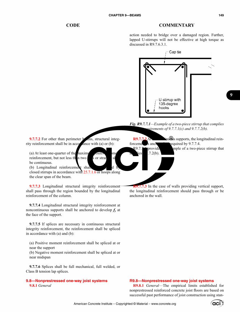
action needed to bridge over a damaged region. Further, lapped U-stirrups will not be effective at high torque as discussed in R9.7.6.3.1.
R9.7.7.2 At noncontinuous supports, the longitudinal rein-forcement is anchored as required by 9.7.7.4.
R9.7.7.1 provides an example of a two-piece stirrup that satisfies 9.7.7.2(b).
R9.7.7.3 In the case of walls providing vertical support, the longitudinal reinforcement should pass through or be anchored in the wall.
R9.8—Nonprestressed one-way joist systems R9.8.1 General—The empirical limits established for
nonprestressed reinforced concrete joist floors are based on successful past performance of joist construction using stan-
9.7.7.2 For other than perimeter beams, structural integ-rity reinforcement shall be in accordance with (a) or (b):
(a) At least one-quarter of the maximum positive moment reinforcement, but not less than two bars or strands, shall be continuous.(b) Longitudinal reinforcement shall be enclosed by closed stirrups in accordance with 25.7.1.6 or hoops along the clear span of the beam.
9.7.7.3 Longitudinal structural integrity reinforcement shall pass through the region bounded by the longitudinal reinforcement of the column.
9.7.7.4 Longitudinal structural integrity reinforcement at noncontinuous supports shall be anchored to develop fy at the face of the support.
9.7.7.5 If splices are necessary in continuous structural integrity reinforcement, the reinforcement shall be spliced in accordance with (a) and (b):
(a) Positive moment reinforcement shall be spliced at or near the support(b) Negative moment reinforcement shall be spliced at or near midspan
9.7.7.6 Splices shall be full mechanical, full welded, or Class B tension lap splices.
9.8—Nonprestressed one-way joist systems 9.8.1 General
Fig. R9.7.7.1—Example of a two-piece stirrup that complies with the requirements of 9.7.7.1(c) and 9.7.7.2(b).
American Concrete Institute – Copyrighted © Material – www.concrete.org
CHAPTER 9—BEAMS 149
CODE COMMENTARY
9
dard joist forming systems. For prestressed joist construc-tion, this section may be used as guide.
R9.8.1.4 A limit on the maximum spacing of ribs is required because of the provisions permitting higher shear strengths and less concrete cover for the reinforcement for these relatively small, repetitive members.
R9.8.1.5 This increase in shear strength is justified on the basis of: 1) satisfactory performance of joist construction designed with higher calculated shear strengths specified in previous Codes which allowed comparable shear stresses; and 2) potential for redistribution of local overloads to adja-cent joists.
9.8.1.1 Nonprestressed one-way joist construction consists of a monolithic combination of regularly spaced ribs and a top slab designed to span in one direction.
9.8.1.2 Width of ribs shall be at least 100 mm at any loca-tion along the depth.
9.8.1.3 Overall depth of ribs shall not exceed 3.5 times the minimum width.
9.8.1.4 Clear spacing between ribs shall not exceed 750 mm.
9.8.1.5 Vc shall be permitted to be taken as 1.1 times the value calculated in 22.5.
9.8.1.6 For structural integrity, at least one bottom bar in each joist shall be continuous and shall be anchored to develop fy at the face of supports.
9.8.1.7 Reinforcement perpendicular to the ribs shall be provided in the slab as required for flexure, considering load concentrations, and shall be at least that required for shrinkage and temperature in accordance with 24.4.
9.8.1.8 One-way joist construction not satisfying the limi-tations of 9.8.1.1 through 9.8.1.4 shall be designed as slabs and beams.
9.8.2 Joist systems with structural fillers
9.8.2.1 If permanent burned clay or concrete tile fillers of material having a unit compressive strength at least equal to fc′ in the joists are used, 9.8.2.1.1 and 9.8.2.1.2 shall apply.
9.8.2.1.1 Slab thickness over fillers shall be at least the greater of one-twelfth the clear distance between ribs and 40 mm.
9.8.2.1.2 For calculation of shear and negative moment strength, it shall be permitted to include the vertical shells of fillers in contact with the ribs. Other portions of fillers shall not be included in strength calculations.
9.8.3 Joist systems with other fillers
9.8.3.1 If fillers not complying with 9.8.2.1 or removable forms are used, slab thickness shall be at least the greater of one-twelfth the clear distance between ribs and 50 mm.
American Concrete Institute – Copyrighted © Material – www.concrete.org
150 BUILDING CODE REQUIREMENTS FOR STRUCTURAL CONCRETE (ACI 318M-14) AND COMMENTARY (ACI 318RM-14)
CODE COMMENTARY
R9.9—Deep beams R9.9.1 General
R9.9.1.1 The behavior of deep beams is discussed in Schlaich et al. (1987), Rogowsky and MacGregor (1986), Marti (1985), and Crist (1966). For a deep beam supporting gravity loads, this provision applies if the loads are applied on the top of the beam and the beam is supported on its bottom face. If the loads are applied through the sides or bottom of such a member, strut-and-tie models, as defined in Chapter 23 should be used to design reinforcement to inter-nally transfer the loads to the top of the beam and distribute them to adjacent supports.
R9.9.1.2 The Code does not contain detailed require-ments for designing deep beams for moment, except that a nonlinear strain distribution should be considered. Guidance for the design of deep beams for flexure is given in Chow et al. (1953), Portland Cement Association (1946), and Park and Paulay (1975).
R9.9.2 Dimensional limits
R9.9.2.1 This limit imposes a dimensional restriction to control cracking under service loads and to guard against diagonal compression failures in deep beams.
R9.9.3 Reinforcement limits
R9.9.3.1 The minimum reinforcement requirements of this section are to be used irrespective of the method used for design and are intended to control the width and propa-gation of inclined cracks. Tests (Rogowsky and MacGregor 1986; Marti 1985; Crist 1966) have shown that vertical shear reinforcement, perpendicular to the longitudinal axis of the member, is more effective for member shear strength than horizontal shear reinforcement, parallel to the longitudinal axis of the member, in a deep beam; however, the specified minimum reinforcement is the same in both directions to control the growth and width of diagonal cracks.
R9.9.4 Reinforcement detailing
9.9—Deep beams 9.9.1 General
9.9.1.1 Deep beams are members that are loaded on one face and supported on the opposite face such that strut-like compression elements can develop between the loads and supports and that satisfy (a) or (b):
(a) Clear span does not exceed four times the overall member depth h(b) Concentrated loads exist within a distance 2h from the face of the support
9.9.1.2 Deep beams shall be designed taking into account nonlinear distribution of longitudinal strain over the depth of the beam.
9.9.1.3 Strut-and-tie models in accordance with Chapter 23 are deemed to satisfy 9.9.1.2.
9.9.2 Dimensional limits
9.9.2.1 Deep beam dimensions shall be selected such that:
0.83≤ φ ′u c wV f b d (9.9.2.1)
9.9.3 Reinforcement limits
9.9.3.1 Distributed reinforcement along the side faces of deep beams shall be at least that required in (a) and (b):
(a) The area of distributed reinforcement perpendicular to the longitudinal axis of the beam, Av, shall be at least 0.0025bws, where s is the spacing of the distributed trans-verse reinforcement.(b) The area of distributed reinforcement parallel to the longitudinal axis of the beam, Avh, shall be at least 0.0025bws2, where s2 is the spacing of the distributed longitudinal reinforcement.
9.9.3.2 The minimum area of flexural tension reinforce-ment, As,min, shall be determined in accordance with 9.6.1.
9.9.4 Reinforcement detailing
9.9.4.1 Concrete cover shall be in accordance with 20.6.1.
9.9.4.2 Minimum spacing for longitudinal reinforcement shall be in accordance with 25.2.
American Concrete Institute – Copyrighted © Material – www.concrete.org
CHAPTER 9—BEAMS 151
CODE COMMENTARY
9
R9.9.4.4 In deep beams, the stress in the longitudinal rein-forcement is more uniform along the length than that of a beam or region that is not deep. High reinforcement stresses normally limited to the center region of a typical beam can extend to the supports in deep beams. Thus, the ends of longitudinal reinforcement may require positive anchorage in the form of standard hooks, bar heads, or other mechan-ical anchorage at supports.
R9.9.4.5 The use of the strut-and-tie method for the design of deep beams illustrates that tensile forces in the bottom tie reinforcement need to be anchored at the face of the support. From this consideration, tie reinforcement should be contin-uous or developed at the face of the support (Rogowsky and MacGregor 1986).
9.9.4.3 Spacing of distributed reinforcement required in 9.9.3.1 shall not exceed the lesser of d/5 and 300 mm.
9.9.4.4 Development of tension reinforcement shall account for distribution of stress in reinforcement that is not directly proportional to the bending moment.
9.9.4.5 At simple supports, positive moment tension rein-forcement shall be anchored to develop fy at the face of the support. If a deep beam is designed using Chapter 23, the positive moment tension reinforcement shall be anchored in accordance with 23.8.2 and 23.8.3.
9.9.4.6 At interior supports, (a) and (b) shall be satisfied:
(a) Negative moment tension reinforcement shall be continuous with that of the adjacent spans.(b) Positive moment tension reinforcement shall be continuous or spliced with that of the adjacent spans.
American Concrete Institute – Copyrighted © Material – www.concrete.org
152 BUILDING CODE REQUIREMENTS FOR STRUCTURAL CONCRETE (ACI 318M-14) AND COMMENTARY (ACI 318RM-14)
CODE COMMENTARY
CHAPTER 10—COLUMNS
10.1—Scope 10.1.1 This chapter shall apply to the design of nonpre-
stressed, prestressed, and composite columns, including reinforced concrete pedestals.
10.1.2 Design of plain concrete pedestals shall be in accor-dance with Chapter 14.
10.2—General 10.2.1 Materials
10.2.1.1 Design properties for concrete shall be selected to be in accordance with Chapter 19.
10.2.1.2 Design properties for steel reinforcement and structural steel used in composite columns shall be selected to be in accordance with Chapter 20.
10.2.1.3 Materials, design, and detailing requirements for embedments in concrete shall be in accordance with 20.7.
10.2.2 Composite columns
10.2.2.1 If a structural steel shape, pipe, or tubing is used as longitudinal reinforcement, the column shall be designed as a composite column.
10.2.3 Connection to other members
10.2.3.1 For cast-in-place construction, beam-column and slab-column joints shall satisfy Chapter 15.
10.2.3.2 For precast construction, connections shall satisfy the force transfer requirements of 16.2.
10.2.3.3 Connections of columns to foundations shall satisfy 16.3.
10.3—Design limits 10.3.1 Dimensional limits
10.3.1.1 For columns with a square, octagonal, or other shaped cross section, it shall be permitted to base gross area considered, required reinforcement, and design strength on a circular section with a diameter equal to the least lateral dimension of the actual shape.
10.3.1.2 For columns with cross sections larger than required by considerations of loading, it shall be permitted to base gross area considered, required reinforcement, and design strength on a reduced effective area, not less than one-half the total area. This provision shall not apply to
R10—COLUMNS
R10.2—General
R10.2.2 Composite columns
R10.2.2.1 Composite columns include both structural steel sections encased in concrete and hollow structural steel sections filled with concrete. Reference to other metals used for reinforcement has been omitted because they are seldom used in concrete construction.
R10.3—Design limits R10.3.1 Dimensional limits—Explicit minimum sizes for
columns are not specified to permit the use of reinforced concrete columns with small cross sections in lightly loaded structures, such as low-rise residential and light office build-ings. If small cross sections are used, there is a greater need for careful workmanship, and shrinkage stresses have increased significance.
R10.3.1.2 In some cases, the gross area of a column is larger than necessary to resist the factored load. In those cases, the minimum reinforcement percentage may be calculated on the basis of the required area rather than the
American Concrete Institute – Copyrighted © Material – www.concrete.org
CHAPTER 10—COLUMNS 153
CODE COMMENTARY
10
provided area, but the area of reinforcement cannot be less than 0.5 percent of the actual cross-sectional area.
R10.3.1.6 Steel-encased concrete sections should have a steel wall thickness large enough to attain the longitudinal yield stress before buckling outward.
R10.4—Required strength
R10.4.2 Factored axial force and moment
R10.4.2.1 The critical load combinations may be difficult to discern without methodically checking each combina-tion. As illustrated in Fig. R10.4.2.1, considering only the factored load combinations associated with maximum axial force (LC1) and with maximum bending moment (LC2) does not necessarily provide a code-compliant design for other load combinations such as LC3.
columns in special moment frames or columns not part of the seismic-force-resisting system required to be designed in accordance with Chapter 18.
10.3.1.3 For columns built monolithically with a concrete wall, the outer limits of the effective cross section of the column shall not be taken greater than 40 mm outside the transverse reinforcement.
10.3.1.4 For columns with two or more interlocking spirals, outer limits of the effective cross section shall be taken at a distance outside the spirals equal to the minimum required concrete cover.
10.3.1.5 If a reduced effective area is considered according to 10.3.1.1 through 10.3.1.4, structural analysis and design of other parts of the structure that interact with the column shall be based on the actual cross section.
10.3.1.6 For composite columns with a concrete core encased by structural steel, the thickness of the steel encase-ment shall be at least (a) or (b):
(a) 3
y
s
fb
E for each face of width b
(b) 8
y
s
fh
E for circular sections of diameter h
10.4—Required strength 10.4.1 General
10.4.1.1 Required strength shall be calculated in accor-dance with the factored load combinations in Chapter 5.
10.4.1.2 Required strength shall be calculated in accor-dance with the analysis procedures in Chapter 6.
10.4.2 Factored axial force and moment
10.4.2.1 Pu and Mu occurring simultaneously for each applicable factored load combination shall be considered.
American Concrete Institute – Copyrighted © Material – www.concrete.org
154 BUILDING CODE REQUIREMENTS FOR STRUCTURAL CONCRETE (ACI 318M-14) AND COMMENTARY (ACI 318RM-14)
CODE COMMENTARY
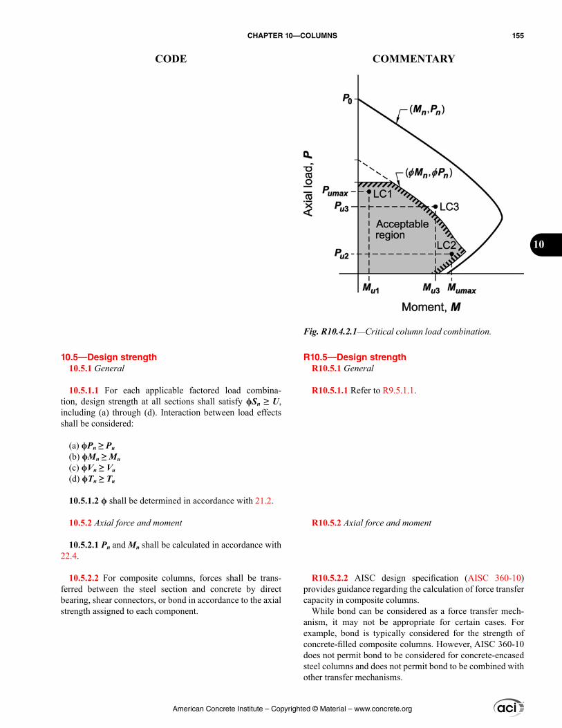
R10.5—Design strength R10.5.1 General
R10.5.1.1 Refer to R9.5.1.1.
R10.5.2 Axial force and moment
R10.5.2.2 AISC design specification (AISC 360-10) provides guidance regarding the calculation of force transfer capacity in composite columns.
While bond can be considered as a force transfer mech-anism, it may not be appropriate for certain cases. For example, bond is typically considered for the strength of concrete-filled composite columns. However, AISC 360-10 does not permit bond to be considered for concrete-encased steel columns and does not permit bond to be combined with other transfer mechanisms.
10.5—Design strength 10.5.1 General
10.5.1.1 For each applicable factored load combina-tion, design strength at all sections shall satisfy ϕSn ≥ U, including (a) through (d). Interaction between load effects shall be considered:
(a) ϕPn ≥ Pu(b) ϕMn ≥ Mu(c) ϕVn ≥ Vu(d) ϕTn ≥ Tu
10.5.1.2 ϕ shall be determined in accordance with 21.2.
10.5.2 Axial force and moment
10.5.2.1 Pn and Mn shall be calculated in accordance with 22.4.
10.5.2.2 For composite columns, forces shall be trans-ferred between the steel section and concrete by direct bearing, shear connectors, or bond in accordance to the axial strength assigned to each component.
Fig. R10.4.2.1—Critical column load combination.
American Concrete Institute – Copyrighted © Material – www.concrete.org
CHAPTER 10—COLUMNS 155
CODE COMMENTARY
10
R10.5.4 Torsion—Torsion acting on columns in buildings is typically negligible and is rarely a governing factor in the design of columns.
R10.6—Reinforcement limits R10.6.1 Minimum and maximum longitudinal reinforcement
R10.6.1.1 Limits are provided for both the minimum and maximum longitudinal reinforcement ratios.
Minimum reinforcement—Reinforcement is necessary to provide resistance to bending, which may exist regard-less of analytical results, and to reduce the effects of creep and shrinkage of the concrete under sustained compressive stresses. Creep and shrinkage tend to transfer load from the concrete to the reinforcement, and the resultant increase in reinforcement stress becomes greater as the reinforcement ratio decreases. Therefore, a minimum limit is placed on the reinforcement ratio to prevent reinforcement from yielding under sustained service loads (Richart 1933).
Maximum reinforcement—The amount of longitudinal reinforcement is limited to ensure that concrete can be effectively consolidated around the bars and to ensure that columns designed according to the Code are similar to the test specimens by which the Code was calibrated. The 0.08 limit applies at all sections, including splice regions, and can also be considered a practical maximum for longitu-dinal reinforcement in terms of economy and requirements for placing. Longitudinal reinforcement in columns should usually not exceed 4 percent if the column bars are required to be lap spliced, as the lap splice zone will have twice as much reinforcement if all lap splices occur at the same location.
R10.6.1.2 Longitudinal and transverse reinforcement is necessary to prevent spalling and ensure that concrete outside the structural steel core behaves as reinforced concrete. Limitations on longitudinal reinforcement are necessary for the reasons described in R10.6.1.1. Transverse reinforcement requirements are provided in 10.7.6.1.4.
For composite columns with a concrete core encased by structural steel, reinforcing bars are not required. The minimum steel wall thickness of 10.3.1.6 inherently provides adequate minimum reinforcement.
R10.6.2 Minimum shear reinforcement
R10.6.2.1 The basis for the minimum shear reinforcement is the same for columns and beams. Refer to R9.6.3 for more information.
10.5.3 Shear
10.5.3.1 Vn shall be calculated in accordance with 22.5.
10.5.4 Torsion
10.5.4.1 If Tu ≥ ϕTth, where Tth is given in 22.7, torsion shall be considered in accordance with Chapter 9.
10.6—Reinforcement limits 10.6.1 Minimum and maximum longitudinal reinforcement
10.6.1.1 For nonprestressed columns and for prestressed columns with average fpe < 1.6 MPa, area of longitudinal reinforcement shall be at least 0.01Ag but shall not exceed 0.08Ag.
10.6.1.2 For composite columns with a structural steel core, area of longitudinal bars located within the transverse reinforcement shall be at least 0.01(Ag – Asx), but shall not exceed 0.08(Ag – Asx).
10.6.2 Minimum shear reinforcement
10.6.2.1 A minimum area of shear reinforcement, Av,min, shall be provided in all regions where Vu > 0.5ϕVc.
American Concrete Institute – Copyrighted © Material – www.concrete.org
156 BUILDING CODE REQUIREMENTS FOR STRUCTURAL CONCRETE (ACI 318M-14) AND COMMENTARY (ACI 318RM-14)
CODE COMMENTARY
R10.7—Reinforcement detailing
R10.7.3 Longitudinal reinforcement
R10.7.3.1 At least four longitudinal bars are required when bars are enclosed by rectangular or circular ties. For other tie shapes, one bar should be provided at each apex or corner and proper transverse reinforcement provided. For example, tied triangular columns require at least three longi-tudinal bars, with one at each apex of the triangular ties. For bars enclosed by spirals, at least six bars are required.
If the number of bars in a circular arrangement is less than eight, the orientation of the bars may significantly affect the moment strength of eccentrically loaded columns and should be considered in design.
10.6.2.2 If shear reinforcement is required, Av,min shall be the greater of (a) and (b):
(a) 0.062 ′ w
cyt
b sf
f
(b) 0.35 w
yt
b sf
10.7—Reinforcement detailing 10.7.1 General
10.7.1.1 Concrete cover for reinforcement shall be in accordance with 20.6.1.
10.7.1.2 Development lengths of deformed and prestressed reinforcement shall be in accordance with 25.4.
10.7.1.3 Bundled bars shall be in accordance with 25.6.
10.7.2 Reinforcement spacing
10.7.2.1 Minimum spacing s shall be in accordance with 25.2.
10.7.3 Longitudinal reinforcement
10.7.3.1 For nonprestressed columns and for prestressed columns with average fpe < 1.6 MPa, the minimum number of longitudinal bars shall be (a), (b), or (c):
(a) Three within triangular ties(b) Four within rectangular or circular ties(c) Six enclosed by spirals or for columns of special moment frames enclosed by circular hoops
10.7.3.2 For composite columns with structural steel cores, a longitudinal bar shall be located at every corner of a rectangular cross section, with other longitudinal bars spaced not farther apart than one-half the least side dimen-sion of the composite column.
10.7.4 Offset bent longitudinal reinforcement
10.7.4.1 The slope of the inclined portion of an offset bent longitudinal bar relative to the longitudinal axis of the column shall not exceed 1 in 6. Portions of bar above and below an offset shall be parallel to axis of column.
10.7.4.2 If the column face is offset 75 mm or more, longi-tudinal bars shall not be offset bent and separate dowels,
American Concrete Institute – Copyrighted © Material – www.concrete.org
CHAPTER 10—COLUMNS 157
CODE COMMENTARY
10
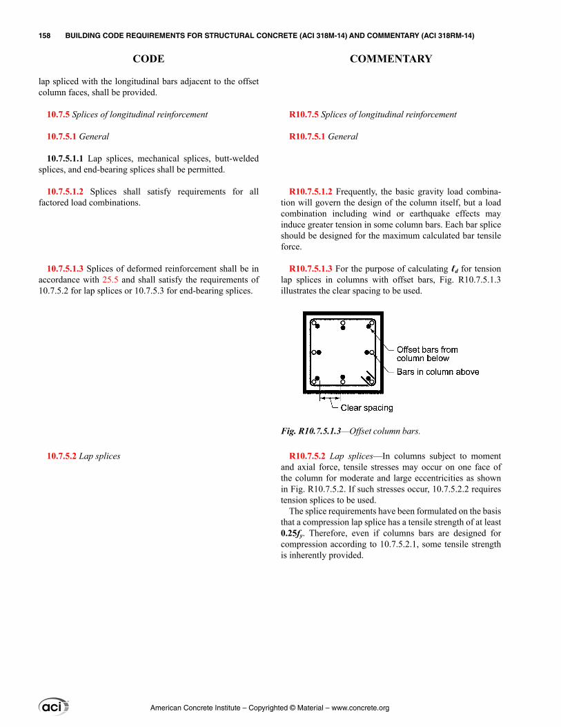
lap spliced with the longitudinal bars adjacent to the offset column faces, shall be provided.
10.7.5 Splices of longitudinal reinforcement
10.7.5.1 General
10.7.5.1.1 Lap splices, mechanical splices, butt-welded splices, and end-bearing splices shall be permitted.
10.7.5.1.2 Splices shall satisfy requirements for all factored load combinations.
10.7.5.1.3 Splices of deformed reinforcement shall be in accordance with 25.5 and shall satisfy the requirements of 10.7.5.2 for lap splices or 10.7.5.3 for end-bearing splices.
10.7.5.2 Lap splices
R10.7.5 Splices of longitudinal reinforcement
R10.7.5.1 General
R10.7.5.1.2 Frequently, the basic gravity load combina-tion will govern the design of the column itself, but a load combination including wind or earthquake effects may induce greater tension in some column bars. Each bar splice should be designed for the maximum calculated bar tensile force.
R10.7.5.1.3 For the purpose of calculating ℓd for tension lap splices in columns with offset bars, Fig. R10.7.5.1.3 illustrates the clear spacing to be used.
R10.7.5.2 Lap splices—In columns subject to moment and axial force, tensile stresses may occur on one face of the column for moderate and large eccentricities as shown in Fig. R10.7.5.2. If such stresses occur, 10.7.5.2.2 requires tension splices to be used.
The splice requirements have been formulated on the basis that a compression lap splice has a tensile strength of at least 0.25fy. Therefore, even if columns bars are designed for compression according to 10.7.5.2.1, some tensile strength is inherently provided.
Fig. R10.7.5.1.3—Offset column bars.
American Concrete Institute – Copyrighted © Material – www.concrete.org
158 BUILDING CODE REQUIREMENTS FOR STRUCTURAL CONCRETE (ACI 318M-14) AND COMMENTARY (ACI 318RM-14)
CODE COMMENTARY
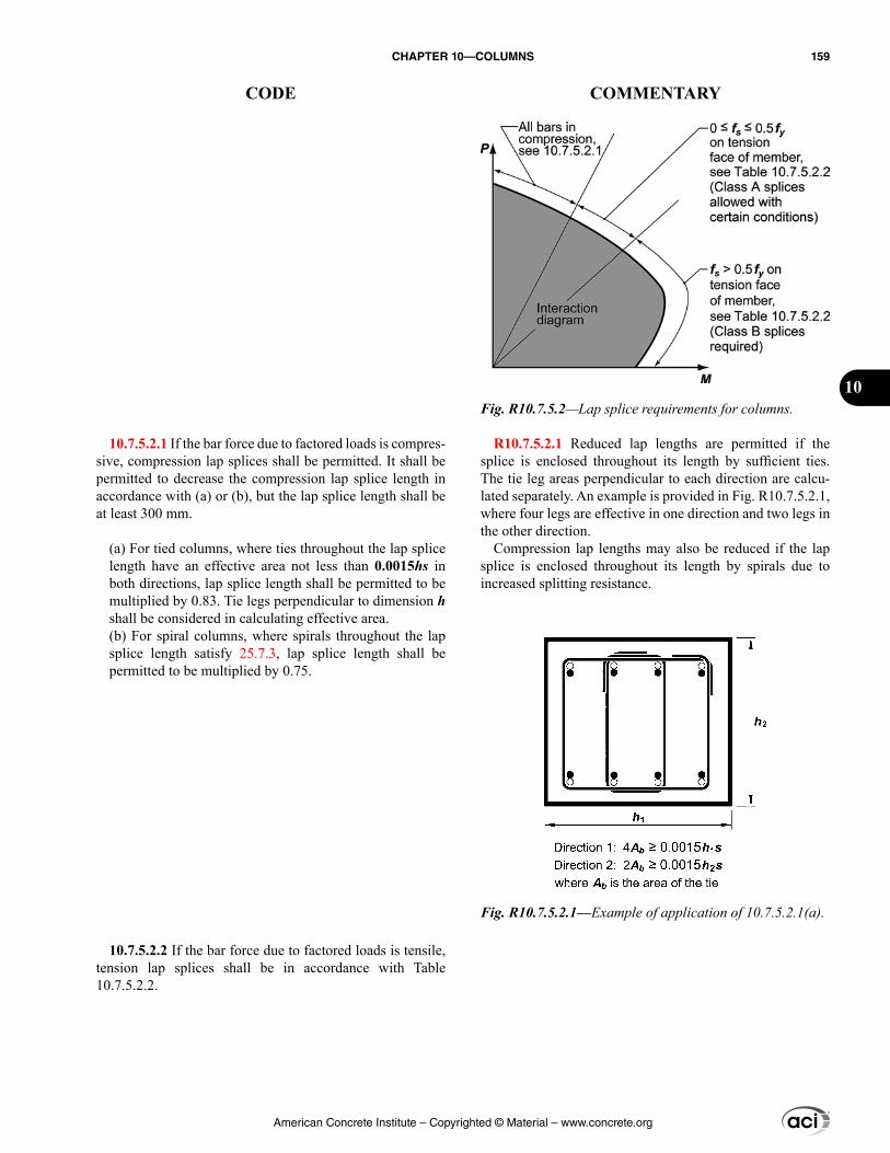
10.7.5.2.1 If the bar force due to factored loads is compres-sive, compression lap splices shall be permitted. It shall be permitted to decrease the compression lap splice length in accordance with (a) or (b), but the lap splice length shall be at least 300 mm.
(a) For tied columns, where ties throughout the lap splice length have an effective area not less than 0.0015hs in both directions, lap splice length shall be permitted to be multiplied by 0.83. Tie legs perpendicular to dimension h shall be considered in calculating effective area.(b) For spiral columns, where spirals throughout the lap splice length satisfy 25.7.3, lap splice length shall be permitted to be multiplied by 0.75.
10.7.5.2.2 If the bar force due to factored loads is tensile, tension lap splices shall be in accordance with Table 10.7.5.2.2.
R10.7.5.2.1 Reduced lap lengths are permitted if the splice is enclosed throughout its length by sufficient ties. The tie leg areas perpendicular to each direction are calcu-lated separately. An example is provided in Fig. R10.7.5.2.1, where four legs are effective in one direction and two legs in the other direction.
Compression lap lengths may also be reduced if the lap splice is enclosed throughout its length by spirals due to increased splitting resistance.
Fig. R10.7.5.2—Lap splice requirements for columns.
Fig. R10.7.5.2.1—Example of application of 10.7.5.2.1(a).
American Concrete Institute – Copyrighted © Material – www.concrete.org
CHAPTER 10—COLUMNS 159
CODE COMMENTARY
10
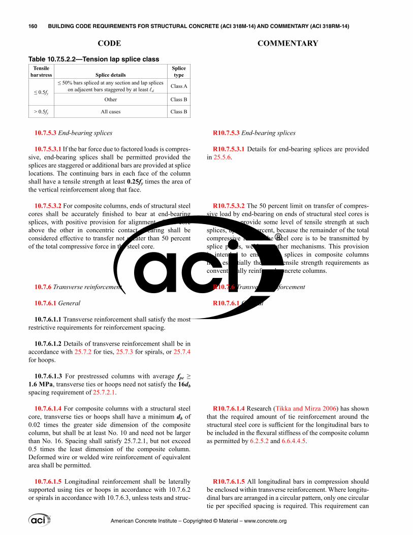
Table 10.7.5.2.2—Tension lap splice classTensile
bar stress Splice detailsSplice type
≤ 0.5fy
≤ 50% bars spliced at any section and lap splices on adjacent bars staggered by at least ℓd
Class A
Other Class B
> 0.5fy All cases Class B
10.7.5.3 End-bearing splices
10.7.5.3.1 If the bar force due to factored loads is compres-sive, end-bearing splices shall be permitted provided the splices are staggered or additional bars are provided at splice locations. The continuing bars in each face of the column shall have a tensile strength at least 0.25fy times the area of the vertical reinforcement along that face.
10.7.5.3.2 For composite columns, ends of structural steel cores shall be accurately finished to bear at end-bearing splices, with positive provision for alignment of one core above the other in concentric contact. Bearing shall be considered effective to transfer not greater than 50 percent of the total compressive force in the steel core.
10.7.6 Transverse reinforcement
10.7.6.1 General
10.7.6.1.1 Transverse reinforcement shall satisfy the most restrictive requirements for reinforcement spacing.
10.7.6.1.2 Details of transverse reinforcement shall be in accordance with 25.7.2 for ties, 25.7.3 for spirals, or 25.7.4 for hoops.
10.7.6.1.3 For prestressed columns with average fpe ≥ 1.6 MPa, transverse ties or hoops need not satisfy the 16db spacing requirement of 25.7.2.1.
10.7.6.1.4 For composite columns with a structural steel core, transverse ties or hoops shall have a minimum db of 0.02 times the greater side dimension of the composite column, but shall be at least No. 10 and need not be larger than No. 16. Spacing shall satisfy 25.7.2.1, but not exceed 0.5 times the least dimension of the composite column. Deformed wire or welded wire reinforcement of equivalent area shall be permitted.
10.7.6.1.5 Longitudinal reinforcement shall be laterally supported using ties or hoops in accordance with 10.7.6.2 or spirals in accordance with 10.7.6.3, unless tests and struc-
R10.7.5.3 End-bearing splices
R10.7.5.3.1 Details for end-bearing splices are provided in 25.5.6.
R10.7.5.3.2 The 50 percent limit on transfer of compres-sive load by end-bearing on ends of structural steel cores is intended to provide some level of tensile strength at such splices, up to 50 percent, because the remainder of the total compressive load in the steel core is to be transmitted by splice plates, welds, or other mechanisms. This provision is intended to ensure that splices in composite columns meet essentially the same tensile strength requirements as conventionally reinforced concrete columns.
R10.7.6 Transverse reinforcement
R10.7.6.1 General
R10.7.6.1.4 Research (Tikka and Mirza 2006) has shown that the required amount of tie reinforcement around the structural steel core is sufficient for the longitudinal bars to be included in the flexural stiffness of the composite column as permitted by 6.2.5.2 and 6.6.4.4.5.
R10.7.6.1.5 All longitudinal bars in compression should be enclosed within transverse reinforcement. Where longitu-dinal bars are arranged in a circular pattern, only one circular tie per specified spacing is required. This requirement can
American Concrete Institute – Copyrighted © Material – www.concrete.org
160 BUILDING CODE REQUIREMENTS FOR STRUCTURAL CONCRETE (ACI 318M-14) AND COMMENTARY (ACI 318RM-14)
CODE COMMENTARY
tural analyses demonstrate adequate strength and feasibility of construction.
10.7.6.1.6 If anchor bolts are placed in the top of a column or pedestal, the bolts shall be enclosed by transverse rein-forcement that also surrounds at least four longitudinal bars within the column or pedestal. The transverse reinforcement shall be distributed within 125 mm of the top of the column or pedestal and shall consist of at least two No. 13 or three No. 10 bars.
10.7.6.2 Lateral support of longitudinal bars using ties or hoops
10.7.6.2.1 In any story, the bottom tie or hoop shall be located not more than one-half the tie or hoop spacing above the top of footing or slab.
10.7.6.2.2 In any story, the top tie or hoop shall be located not more than one-half the tie or hoop spacing below the lowest horizontal reinforcement in the slab, drop panel, or shear cap. If beams or brackets frame into all sides of the column, the top tie or hoop shall be located not more than 75 mm below the lowest horizontal reinforcement in the shallowest beam or bracket.
10.7.6.3 Lateral support of longitudinal bars using spirals
10.7.6.3.1 In any story, the bottom of the spiral shall be located at the top of footing or slab.
10.7.6.3.2 In any story, the top of the spiral shall be located in accordance with Table 10.7.6.3.2.
be satisfied by a continuous circular tie (helix), with the maximum pitch being equal to the required tie spacing.
It is prudent to provide a set of ties at each end of lap spliced bars, above and below end-bearing splices, and at minimum spacings immediately below sloping regions of offset bent bars.
Precast columns with cover less than 40 mm, prestressed columns without longitudinal bars, columns of concrete with small size coarse aggregate, wall-like columns, and other unusual columns may require special designs for transverse reinforcement.
R10.7.6.1.6 Confinement improves load transfer from the anchor bolts to the column or pier where concrete cracks in the vicinity of the bolts. Such cracking can occur due to unanticipated forces caused by temperature, restrained shrinkage, and similar effects.
R10.7.6.2 Lateral support of longitudinal bars using ties or hoops
R10.7.6.2.2 For rectangular columns, beams or brackets framing into all four sides at the same elevation are consid-ered to provide restraint over a joint depth equal to that of the shallowest beam or bracket. For columns with other shapes, four beams framing into the column from two orthogonal directions are considered to provide equivalent restraint.
R10.7.6.3 Lateral support of longitudinal bars using spirals
R10.7.6.3.2 Refer to R10.7.6.2.2.
American Concrete Institute – Copyrighted © Material – www.concrete.org
CHAPTER 10—COLUMNS 161
CODE COMMENTARY
10
Table 10.7.6.3.2 —Spiral extension requirements at top of column
Framing at column end Extension requirements
Beams or brackets frame into all sides of the column
Extend to the level of the lowest horizontal reinforcement in members supported above.
Beams or brackets do not frame into all sides of the column
Extend to the level of the lowest horizontal reinforcement in members supported above.Additional column ties shall extend above termination of spiral to bottom of slab, drop panel, or shear cap.
Columns with capitalsExtend to the level at which the diam-eter or width of capital is twice that of the column.
10.7.6.4 Lateral support of offset bent longitudinal bars
10.7.6.4.1 Where longitudinal bars are offset, horizontal support shall be provided by ties, hoops, spirals, or parts of the floor construction and shall be designed to resist 1.5 times the horizontal component of the calculated force in the inclined portion of the offset bar.
10.7.6.4.2 If transverse reinforcement is provided to resist forces that result from offset bends, ties, hoops, or spirals shall be placed not more than 150 mm from points of bend.
10.7.6.5 Shear
10.7.6.5.1 If required, shear reinforcement shall be provided using ties, hoops, or spirals.
10.7.6.5.2 Maximum spacing of shear reinforcement shall be in accordance with Table 10.7.6.5.2.
Table 10.7.6.5.2—Maximum spacing of shear reinforcement
Vs
Maximum s, mmNonprestressed
columnPrestressed
column
0.33≤ ′c wf b d Lesser of:d/2 3h/4
600
0.33> ′c wf b d Lesser of:d/4 3h/8
300
American Concrete Institute – Copyrighted © Material – www.concrete.org
162 BUILDING CODE REQUIREMENTS FOR STRUCTURAL CONCRETE (ACI 318M-14) AND COMMENTARY (ACI 318RM-14)
CODE COMMENTARY
CHAPTER 11—WALLS
11.1—Scope 11.1.1 This chapter shall apply to the design of nonpre-
stressed and prestressed walls including (a) through (c):
(a) Cast-in-place(b) Precast in-plant(c) Precast on-site including tilt-up
11.1.2 Design of special structural walls shall be in accor-dance with Chapter 18.
11.1.3 Design of plain concrete walls shall be in accor-dance with Chapter 14.
11.1.4 Design of cantilever retaining walls shall be in accordance with 22.2 through 22.4, with minimum hori-zontal reinforcement in accordance with 11.6.
11.1.5 Design of walls as grade beams shall be in accor-dance with 13.3.5.
11.2—General 11.2.1 Materials
11.2.1.1 Design properties for concrete shall be selected to be in accordance with Chapter 19.
11.2.1.2 Design properties for steel reinforcement shall be selected to be in accordance with Chapter 20.
11.2.1.3 Materials, design, and detailing requirements for embedments in concrete shall be in accordance with 20.7.
11.2.2 Connection to other members
11.2.2.1 For precast walls, connections shall be designed in accordance with 16.2.
11.2.2.2 Connections of walls to foundations shall satisfy 16.3.
R11—WALLS
R11.1—Scope R11.1.1 This chapter applies generally to walls as vertical
and lateral force-resisting members. Provisions for in-plane shear in ordinary structural walls, as opposed to special structural walls conforming to 18.10, are included in this chapter.
R11.1.2 Special structural walls are detailed according to the provisions of 18.10. This Code uses the term “structural wall” as being synonymous with “shear wall.” While the term “shear wall” is not defined in this Code, the definition of a structural wall in Chapter 2 states “a shear wall is a structural wall.”
ASCE 7 defines a structural wall as a wall that meets the definition for a bearing wall or a shear wall. A bearing wall is defined as a wall that supports vertical load beyond a certain threshold value. A shear wall is defined as a wall, bearing or nonbearing, designed to resist lateral forces acting in the plane of the wall. ASCE 7 definitions are widely accepted.
R11.2—General
American Concrete Institute – Copyrighted © Material – www.concrete.org
CHAPTER 11—WALLS 163
CODE COMMENTARY
11
R11.2.4 Intersecting elements
R11.2.4.1 Walls that do not depend on intersecting elements for support, do not have to be connected to those elements. It is not uncommon to separate massive retaining walls from intersecting walls to accommodate differences in deformations.
R11.3—Design limits R11.3.1 Minimum wall thickness
R11.3.1.1 The minimum thickness requirements need not be applied to bearing walls and exterior basement and foun-dation walls designed by 11.5.2 or analyzed by 11.8.
R11.4—Required strength R11.4.1 General
R11.4.1.3 The forces typically acting on a wall are illus-trated in Fig. R11.4.1.3.
11.2.3 Load distribution
11.2.3.1 Unless otherwise demonstrated by an analysis, the horizontal length of wall considered as effective for resisting each concentrated load shall not exceed the lesser of the center-to-center distance between loads, and the bearing width plus four times the wall thickness. Effec-tive horizontal length for bearing shall not extend beyond vertical wall joints unless design provides for transfer of forces across the joints.
11.2.4 Intersecting elements
11.2.4.1 Walls shall be anchored to intersecting elements, such as floors and roofs; columns, pilasters, buttresses, or intersecting walls; and to footings.
11.3—Design limits 11.3.1 Minimum wall thickness
11.3.1.1 Minimum wall thicknesses shall be in accordance with Table 11.3.1.1. Thinner walls are permitted if adequate strength and stability can be demonstrated by structural analysis.
Table 11.3.1.1—Minimum wall thickness h
Wall type Minimum thickness h
Bearing[1] Greater of:100 mm (a)
1/25 the lesser of unsupported length and unsupported height (b)
Nonbearing Greater of:100 mm (c)
1/30 the lesser of unsupported length and unsupported height (d)
Exterior basement and foundation[1]
190 mm (e)
[1]Only applies to walls designed in accordance with the simplified design method of 11.5.3.
11.4—Required strength 11.4.1 General
11.4.1.1 Required strength shall be calculated in accor-dance with the factored load combinations in Chapter 5.
11.4.1.2 Required strength shall be calculated in accor-dance with the analysis procedures in Chapter 6.
11.4.1.3 Slenderness effects shall be calculated in accor-dance with 6.6.4, 6.7, or 6.8. Alternatively, out-of-plane slenderness analysis shall be permitted using 11.8 for walls meeting the requirements of that section.
American Concrete Institute – Copyrighted © Material – www.concrete.org
164 BUILDING CODE REQUIREMENTS FOR STRUCTURAL CONCRETE (ACI 318M-14) AND COMMENTARY (ACI 318RM-14)
CODE COMMENTARY
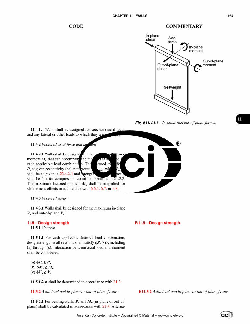
R11.5—Design strength
R11.5.2 Axial load and in-plane or out-of-plane flexure
11.4.1.4 Walls shall be designed for eccentric axial loads and any lateral or other loads to which they are subjected.
11.4.2 Factored axial force and moment
11.4.2.1 Walls shall be designed for the maximum factored moment Mu that can accompany the factored axial force for each applicable load combination. The factored axial force Pu at given eccentricity shall not exceed ϕPn,max, where Pn,max shall be as given in 22.4.2.1 and strength reduction factor ϕ shall be that for compression-controlled sections in 21.2.2. The maximum factored moment Mu shall be magnified for slenderness effects in accordance with 6.6.4, 6.7, or 6.8.
11.4.3 Factored shear
11.4.3.1 Walls shall be designed for the maximum in-plane Vu and out-of-plane Vu.
11.5—Design strength 11.5.1 General
11.5.1.1 For each applicable factored load combination, design strength at all sections shall satisfy ϕSn ≥ U, including (a) through (c). Interaction between axial load and moment shall be considered.
(a) ϕPn ≥ Pu(b) ϕMn ≥ Mu(c) ϕVn ≥ Vu
11.5.1.2 ϕ shall be determined in accordance with 21.2.
11.5.2 Axial load and in-plane or out-of-plane flexure
11.5.2.1 For bearing walls, Pn and Mn (in-plane or out-of-plane) shall be calculated in accordance with 22.4. Alterna-
Fig. R11.4.1.3—In-plane and out-of-plane forces.
American Concrete Institute – Copyrighted © Material – www.concrete.org
CHAPTER 11—WALLS 165
CODE COMMENTARY
11
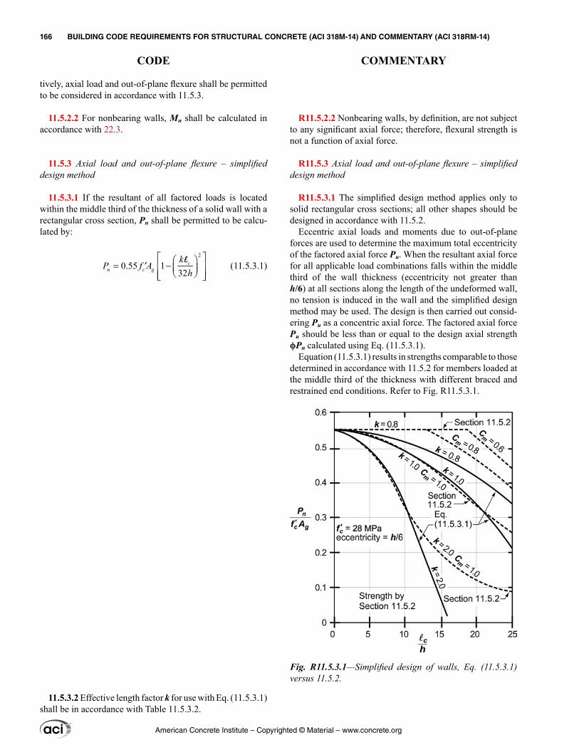
R11.5.2.2 Nonbearing walls, by definition, are not subject to any significant axial force; therefore, flexural strength is not a function of axial force.
R11.5.3 Axial load and out-of-plane flexure – simplified design method
R11.5.3.1 The simplified design method applies only to solid rectangular cross sections; all other shapes should be designed in accordance with 11.5.2.
Eccentric axial loads and moments due to out-of-plane forces are used to determine the maximum total eccentricity of the factored axial force Pu. When the resultant axial force for all applicable load combinations falls within the middle third of the wall thickness (eccentricity not greater than h/6) at all sections along the length of the undeformed wall, no tension is induced in the wall and the simplified design method may be used. The design is then carried out consid-ering Pu as a concentric axial force. The factored axial force Pu should be less than or equal to the design axial strength ϕPn calculated using Eq. (11.5.3.1).
Equation (11.5.3.1) results in strengths comparable to those determined in accordance with 11.5.2 for members loaded at the middle third of the thickness with different braced and restrained end conditions. Refer to Fig. R11.5.3.1.
tively, axial load and out-of-plane flexure shall be permitted to be considered in accordance with 11.5.3.
11.5.2.2 For nonbearing walls, Mn shall be calculated in accordance with 22.3.
11.5.3 Axial load and out-of-plane flexure – simplified design method
11.5.3.1 If the resultant of all factored loads is located within the middle third of the thickness of a solid wall with a rectangular cross section, Pn shall be permitted to be calcu-lated by:
2
0.55 132
cn c g
kP f A
h = −′
l (11.5.3.1)
11.5.3.2 Effective length factor k for use with Eq. (11.5.3.1) shall be in accordance with Table 11.5.3.2.
Fig. R11.5.3.1—Simplified design of walls, Eq. (11.5.3.1) versus 11.5.2.
American Concrete Institute – Copyrighted © Material – www.concrete.org
166 BUILDING CODE REQUIREMENTS FOR STRUCTURAL CONCRETE (ACI 318M-14) AND COMMENTARY (ACI 318RM-14)
CODE COMMENTARY
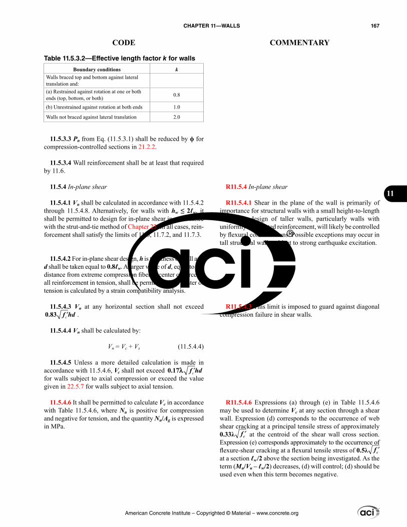
R11.5.4 In-plane shear
R11.5.4.1 Shear in the plane of the wall is primarily of importance for structural walls with a small height-to-length ratio. The design of taller walls, particularly walls with uniformly distributed reinforcement, will likely be controlled by flexural considerations. Possible exceptions may occur in tall structural walls subject to strong earthquake excitation.
R11.5.4.3 This limit is imposed to guard against diagonal compression failure in shear walls.
R11.5.4.6 Expressions (a) through (e) in Table 11.5.4.6 may be used to determine Vc at any section through a shear wall. Expression (d) corresponds to the occurrence of web shear cracking at a principal tensile stress of approximately 0.33λ ′fc at the centroid of the shear wall cross section. Expression (e) corresponds approximately to the occurrence of flexure-shear cracking at a flexural tensile stress of 0.5λ ′fc at a section ℓw/2 above the section being investigated. As the term (Mu/Vu – ℓw/2) decreases, (d) will control; (d) should be used even when this term becomes negative.
Table 11.5.3.2—Effective length factor k for walls
Boundary conditions kWalls braced top and bottom against lateral translation and:(a) Restrained against rotation at one or both ends (top, bottom, or both) 0.8
(b) Unrestrained against rotation at both ends 1.0
Walls not braced against lateral translation 2.0
11.5.3.3 Pn from Eq. (11.5.3.1) shall be reduced by ϕ for compression-controlled sections in 21.2.2.
11.5.3.4 Wall reinforcement shall be at least that required by 11.6.
11.5.4 In-plane shear
11.5.4.1 Vn shall be calculated in accordance with 11.5.4.2 through 11.5.4.8. Alternatively, for walls with hw ≤ 2ℓw, it shall be permitted to design for in-plane shear in accordance with the strut-and-tie method of Chapter 23. In all cases, rein-forcement shall satisfy the limits of 11.6, 11.7.2, and 11.7.3.
11.5.4.2 For in-plane shear design, h is thickness of wall and d shall be taken equal to 0.8ℓw. A larger value of d, equal to the distance from extreme compression fiber to center of force of all reinforcement in tension, shall be permitted if the center of tension is calculated by a strain compatibility analysis.
11.5.4.3 Vn at any horizontal section shall not exceed ′c0.83 f hd .
11.5.4.4 Vn shall be calculated by:
Vn = Vc + Vs (11.5.4.4)
11.5.4.5 Unless a more detailed calculation is made in accordance with 11.5.4.6, Vc shall not exceed ′c0.17λ f hd for walls subject to axial compression or exceed the value given in 22.5.7 for walls subject to axial tension.
11.5.4.6 It shall be permitted to calculate Vc in accordance with Table 11.5.4.6, where Nu is positive for compression and negative for tension, and the quantity Nu/Ag is expressed in MPa.
American Concrete Institute – Copyrighted © Material – www.concrete.org
CHAPTER 11—WALLS 167
CODE COMMENTARY
11
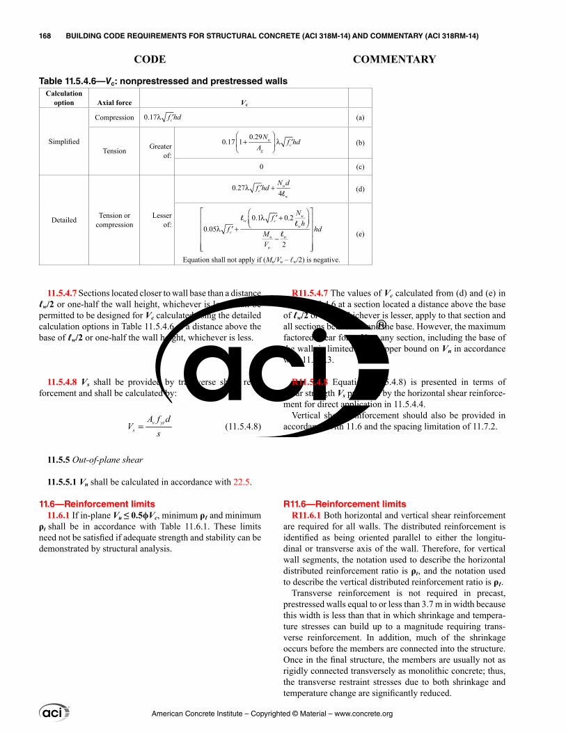
11.5.4.7 Sections located closer to wall base than a distance ℓw/2 or one-half the wall height, whichever is less, shall be permitted to be designed for Vc calculated using the detailed calculation options in Table 11.5.4.6 at a distance above the base of ℓw/2 or one-half the wall height, whichever is less.
11.5.4.8 Vs shall be provided by transverse shear rein-forcement and shall be calculated by:
v yts
A f dV
s= (11.5.4.8)
11.5.5 Out-of-plane shear
11.5.5.1 Vn shall be calculated in accordance with 22.5.
11.6—Reinforcement limits 11.6.1 If in-plane Vu ≤ 0.5ϕVc, minimum ρℓ and minimum
ρt shall be in accordance with Table 11.6.1. These limits need not be satisfied if adequate strength and stability can be demonstrated by structural analysis.
R11.5.4.7 The values of Vc calculated from (d) and (e) in Table 11.5.4.6 at a section located a distance above the base of ℓw/2 or hw/2, whichever is lesser, apply to that section and all sections between it and the base. However, the maximum factored shear force Vu at any section, including the base of the wall, is limited to the upper bound on Vn in accordance with 11.5.4.3.
R11.5.4.8 Equation (11.5.4.8) is presented in terms of shear strength Vs provided by the horizontal shear reinforce-ment for direct application in 11.5.4.4.
Vertical shear reinforcement should also be provided in accordance with 11.6 and the spacing limitation of 11.7.2.
R11.6—Reinforcement limits R11.6.1 Both horizontal and vertical shear reinforcement
are required for all walls. The distributed reinforcement is identified as being oriented parallel to either the longitu-dinal or transverse axis of the wall. Therefore, for vertical wall segments, the notation used to describe the horizontal distributed reinforcement ratio is ρt, and the notation used to describe the vertical distributed reinforcement ratio is ρℓ.
Transverse reinforcement is not required in precast, prestressed walls equal to or less than 3.7 m in width because this width is less than that in which shrinkage and tempera-ture stresses can build up to a magnitude requiring trans-verse reinforcement. In addition, much of the shrinkage occurs before the members are connected into the structure. Once in the final structure, the members are usually not as rigidly connected transversely as monolithic concrete; thus, the transverse restraint stresses due to both shrinkage and temperature change are significantly reduced.
Table 11.5.4.6—Vc: nonprestressed and prestressed wallsCalculation
option Axial force Vc
Simplified
Compression 0.17λ ′cf hd (a)
Tension Greaterof:
0.290.17 1
+ λ ′
u
cg
Nf hd
A(b)
0 (c)
Detailed Tension or compression
Lesserof:
0.274
λ +′ uc
w
N df hd
l(d)
0.1 0.20.05
2
λ +′ λ +′
−
uw c
wc
u w
u
Nfh
f hdMV
ll
l
Equation shall not apply if (Mu/Vu – ℓw/2) is negative.
(e)
American Concrete Institute – Copyrighted © Material – www.concrete.org
168 BUILDING CODE REQUIREMENTS FOR STRUCTURAL CONCRETE (ACI 318M-14) AND COMMENTARY (ACI 318RM-14)
CODE COMMENTARY
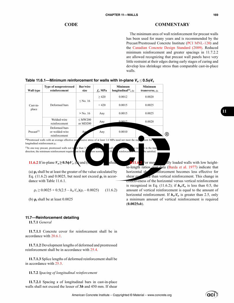
11.6.2 If in-plane Vu ≥ 0.5ϕVc, (a) and (b) shall be satisfied:
(a) ρℓ shall be at least the greater of the value calculated by Eq. (11.6.2) and 0.0025, but need not exceed ρt in accor-dance with Table 11.6.1.
ρℓ ≥ 0.0025 + 0.5(2.5 – hw/ℓw)(ρt – 0.0025) (11.6.2)
(b) ρt shall be at least 0.0025
11.7—Reinforcement detailing11.7.1 General
11.7.1.1 Concrete cover for reinforcement shall be in accordance with 20.6.1.
11.7.1.2 Development lengths of deformed and prestressed reinforcement shall be in accordance with 25.4.
11.7.1.3 Splice lengths of deformed reinforcement shall be in accordance with 25.5.
11.7.2 Spacing of longitudinal reinforcement
11.7.2.1 Spacing s of longitudinal bars in cast-in-place walls shall not exceed the lesser of 3h and 450 mm. If shear
The minimum area of wall reinforcement for precast walls has been used for many years and is recommended by the Precast/Prestressed Concrete Institute (PCI MNL-120) and the Canadian Concrete Design Standard (2009). Reduced minimum reinforcement and greater spacings in 11.7.2.2 are allowed recognizing that precast wall panels have very little restraint at their edges during early stages of curing and develop less shrinkage stress than comparable cast-in-place walls.
R11.6.2 For monotonically loaded walls with low height-to-length ratios, test data (Barda et al. 1977) indicate that horizontal shear reinforcement becomes less effective for shear resistance than vertical reinforcement. This change in effectiveness of the horizontal versus vertical reinforcement is recognized in Eq. (11.6.2); if hw/ℓw is less than 0.5, the amount of vertical reinforcement is equal to the amount of horizontal reinforcement. If hw/ℓw is greater than 2.5, only a minimum amount of vertical reinforcement is required (0.0025sh).
Table 11.6.1—Minimum reinforcement for walls with in-plane Vu ≤ 0.5ϕVc
Wall typeType of nonprestressed
reinforcementBar/wire
size fy, MPaMinimum
longitudinal[1], ρℓMinimum
transverse, ρt
Cast-in-place
Deformed bars≤ No. 16
≥ 420 0.0012 0.0020
< 420 0.0015 0.0025
> No. 16 Any 0.0015 0.0025
Welded-wire reinforcement
≤ MW200 or MD200 Any 0.0012 0.0020
Precast[2]Deformed bars or welded-wire reinforcement
Any Any 0.0010 0.0010
[1]Prestressed walls with an average effective compressive stress of at least 1.6 MPa need not meet the requirement for minimum longitudinal reinforcement ρℓ.[2]In one-way precast, prestressed walls not wider than 3.7 m and not mechanically connected to cause restraint in the transverse direction, the minimum reinforcement requirement in the direction normal to the flexural reinforcement need not be satisfied.
American Concrete Institute – Copyrighted © Material – www.concrete.org
CHAPTER 11—WALLS 169
CODE COMMENTARY
11
reinforcement is required for in-plane strength, spacing of longitudinal reinforcement shall not exceed ℓw/3.
11.7.2.2 Spacing s of longitudinal bars in precast walls shall not exceed the lesser of (a) and (b):
(a) 5h(b) 450 mm for exterior walls or 750 mm for interior walls
If shear reinforcement is required for in-plane strength, s shall not exceed the smallest of 3h, 450 mm, and ℓw/3.
11.7.2.3 For walls with h greater than 250 mm, except basement walls and cantilever retaining walls, distributed reinforcement for each direction shall be placed in two layers parallel with wall faces in accordance with (a) and (b):
(a) One layer consisting of at least one-half and not exceeding two-thirds of total reinforcement required for each direction shall be placed at least 50 mm, but not exceeding h/3, from the exterior surface.(b) The other layer consisting of the balance of required reinforcement in that direction, shall be placed at least 20 mm, but not greater than h/3, from the interior surface.
11.7.2.4 Flexural tension reinforcement shall be well distributed and placed as close as practicable to the tension face.
11.7.3 Spacing of transverse reinforcement
11.7.3.1 Spacing s of transverse reinforcement in cast-in-place walls shall not exceed the lesser of 3h and 450 mm. If shear reinforcement is required for in-plane strength, s shall not exceed ℓw/5.
11.7.3.2 Spacing s of transverse bars in precast walls shall not exceed the lesser of (a) and (b):
(a) 5h(b) 450 mm for exterior walls or 750 mm for interior walls
If shear reinforcement is required for in-plane strength, s shall not exceed the least of 3h, 450 mm, and ℓw/5
11.7.4 Lateral support of longitudinal reinforcement
11.7.4.1 If longitudinal reinforcement is required for axial strength or if Ast exceeds 0.01Ag, longitudinal reinforcement shall be laterally supported by transverse ties.
11.7.5 Reinforcement around openings
11.7.5.1 In addition to the minimum reinforcement required by 11.6, at least two No. 16 bars in walls having two layers of reinforcement in both directions and one No. 16 bar
American Concrete Institute – Copyrighted © Material – www.concrete.org
170 BUILDING CODE REQUIREMENTS FOR STRUCTURAL CONCRETE (ACI 318M-14) AND COMMENTARY (ACI 318RM-14)
CODE COMMENTARY
in walls having a single layer of reinforcement in both direc-tions shall be provided around window, door, and similarly sized openings. Such bars shall be anchored to develop fy in tension at the corners of the openings.
11.8—Alternative method for out-of-plane slender wall analysis
11.8.1 General
11.8.1.1 It shall be permitted to analyze out-of-plane slen-derness effects in accordance with this section for walls satisfying (a) through (e):
(a) Cross section is constant over the height of the wall(b) Wall is tension-controlled for out-of-plane moment effect(c) ϕMn is at least Mcr, where Mcr is calculated using fr as provided in 19.2.3(d) Pu at the midheight section does not exceed 0.06fc′Ag(e) Calculated out-of-plane deflection due to service loads, ∆s, including P∆ effects, does not exceed ℓc/150
11.8.2 Modeling
11.8.2.1 The wall shall be analyzed as a simply supported, axially loaded member subject to an out-of-plane uniformly distributed lateral load, with maximum moments and deflec-tions occurring at midheight.
11.8.2.2 Concentrated gravity loads applied to the wall above any section shall be assumed to be distributed over a width equal to the bearing width, plus a width on each side that increases at a slope of 2 vertical to 1 horizontal, but not extending beyond (a) or (b):
(a) The spacing of the concentrated loads(b) The edges of the wall panel
11.8.3 Factored moment
11.8.3.1 Mu at midheight of wall due to combined flexure and axial loads shall include the effects of wall deflection in accordance with (a) or (b):
(a) By iterative calculation using
Mu = Mua + Pu∆u (11.8.3.1a)
where Mua is the maximum factored moment at midheight of wall due to lateral and eccentric vertical loads, not including P∆ effects.∆u shall be calculated by:
25
(0.75)48u c
uc cr
ME I
∆ =l
(11.8.3.1b)
R11.8—Alternative method for out-of-plane slender wall analysis
R11.8.1 General
R11.8.1.1 This procedure is presented as an alternative to the requirements of 11.5.2.1 for the out-of-plane design of slender wall panels, where the panels are restrained against rotation at the top.
Panels that have windows or other large openings are not considered to have constant cross section over the height of the panel. Such walls are to be designed taking into account the effects of openings.
Many aspects of the design of tilt-up walls and buildings are discussed in ACI 551.2R and Carter et al. (1993).
R11.8.3 Factored moment
R11.8.3.1 The neutral axis depth c in Eq. (11.8.3.1c) corresponds to the following effective area of longitudinal reinforcement.
,/2u
se w sy
P hA Af d
= +
American Concrete Institute – Copyrighted © Material – www.concrete.org
CHAPTER 11—WALLS 171
CODE COMMENTARY
11
where Icr shall be calculated by:
3
2( )2 3
s u wcr s
c y
E P chI A d cE f d
= + − +
l
(11.8.3.1c)
and the value of Es/Ec shall be at least 6.(b) By direct calculation using:
25
1(0.75)48
uau
u c
c cr
MM
PE I
=
− l
(11.8.3.1d)
11.8.4 Out-of-plane deflection – service loads
11.8.4.1 Out-of-plane deflection due to service loads, ∆s, shall be calculated in accordance with Table 11.8.4.1, where Ma is calculated by 11.8.4.2.
Table 11.8.4.1—Calculation of ∆s
Ma ∆s
≤ (2/3)Mcra
s crcr
MM
∆ = ∆
(a)
> (2/3)Mcr( )
( )( ) ( )(2/3)(2/3) (2/3)
2 3a cr
s cr n crn cr
M MM M
−∆ = ∆ + ∆ − ∆
− (b)
11.8.4.2 The maximum moment Ma at midheight of wall due to service lateral and eccentric vertical loads, including Ps∆s effects, shall be calculated by Eq. (11.8.4.2) with itera-tion of deflections.
Ma = Msa + Ps∆s (11.8.4.2)
11.8.4.3 ∆cr and ∆n shall be calculated by (a) and (b):
(a) 25
48cr c
crc g
ME I
∆ =l
(11.8.4.3a)
(b) 25
48n c
nc cr
ME I
∆ =l
(11.8.4.3b)
11.8.4.4 Icr shall be calculated by Eq. (11.8.3.1c).
R11.8.4 Out-of-plane deflection – service loads
R11.8.4.1 Test data (Athey 1982) demonstrate that out-of-plane deflections increase rapidly when the service-level moment exceeds 2/3Mcr. A linear interpolation between ∆cr and ∆n is used to determine ∆s to simplify the design of slender walls if Ma > 2/3Mcr.
Service-level load combinations are not defined in Chapter 5 of this Code, but they are discussed in Appendix C of ASCE/SEI 7. Appendixes to ASCE/SEI 7 are not considered mandatory parts of that standard. For calculating service-level lateral deflections of structures, Appendix C of ASCE/SEI 7 recommends using the following load combination:
D + 0.5L + Wa
in which Wa is wind load based on serviceability wind speeds provided in the commentary to Appendix C of ASCE/SEI 7. If the slender wall is designed to resist earthquake effects E, and E is based on strength-level earthquake effects, the following load combination is considered to be appropriate for evaluating the service-level lateral deflections
D + 0.5L + 0.7E
American Concrete Institute – Copyrighted © Material – www.concrete.org
172 BUILDING CODE REQUIREMENTS FOR STRUCTURAL CONCRETE (ACI 318M-14) AND COMMENTARY (ACI 318RM-14)
CODE COMMENTARY
CHAPTER 12—DIAPHRAGMS
12.1—Scope 12.1.1 This chapter shall apply to the design of nonpre-
stressed and prestressed diaphragms, including (a) through (d):
(a) Diaphragms that are cast-in-place slabs(b) Diaphragms that comprise a cast-in-place topping slab on precast elements(c) Diaphragms that comprise precast elements with end strips formed by either a cast-in-place concrete topping slab or edge beams(d) Diaphragms of interconnected precast elements without cast-in-place concrete topping
12.1.2 Diaphragms in structures assigned to Seismic Design Category D, E, or F shall also satisfy requirements of 18.12.
12.2—General 12.2.1 Design shall consider (a) through (e):
(a) Diaphragm in-plane forces due to lateral loads acting on the building(b) Diaphragm transfer forces(c) Connection forces between the diaphragm and vertical framing or nonstructural elements(d) Forces resulting from bracing vertical or sloped building elements(e) Diaphragm out-of-plane forces due to gravity and other loads applied to the diaphragm surface
R12—DIAPHRAGMS
R12.1—Scope R12.1.1 Diaphragms typically are horizontal or nearly
horizontal planar elements that serve to transfer lateral forces to vertical elements of the lateral-force-resisting system (Fig. R12.1.1). Diaphragms also tie the building elements together into a complete three-dimensional system and provide lateral support to those elements by connecting them to the lateral-force-resisting system. Typically, diaphragms also serve as floor and roof slabs, or as parking structure ramps and, therefore, support gravity loads. A diaphragm may include chords and collectors.
When subjected to lateral loads, such as the in-plane iner-tial loads acting on the roof diaphragm of Fig. R12.1.1, a diaphragm acts essentially as a beam spanning horizon-tally between vertical elements of the lateral-force-resisting system. The diaphragm thus develops in-plane bending moments, shears, and possibly other actions. Where vertical elements of the lateral-force-resisting system do not extend along the full depth of the diaphragm, collectors may be required to collect the diaphragm shear and transfer it to the vertical elements. The term “distributor” is sometimes used to describe a collector that transfers force from a vertical element of the lateral-force-resisting system into the diaphragm. This chapter describes minimum requirements for diaphragm and collector design and detailing, including configuration, analysis models, materials, and strength.
This chapter covers only the types of diaphragms listed in this provision. Other diaphragm types, such as horizontal trusses, are used successfully in buildings, but this chapter does not include prescriptive provisions for those other types.
R12.2—General R12.2.1 As partially illustrated in Fig. R12.1.1, diaphragms
resist forces from several types of actions (Moehle et al. 2010):
(a) Diaphragm in-plane forces—Lateral forces from load combinations including wind, earthquake, and horizontal fluid or soil pressure generate in-plane shear, axial, and bending actions in diaphragms as they span between, and transfer forces to, vertical elements of the lateral-force-resisting system. For wind loading, lateral force is gener-ated by wind pressure acting on building cladding that is transferred by diaphragms to the vertical elements. For earthquake loading, inertial forces are generated within the diaphragm and tributary portions of walls, columns, and other elements, and then transferred by diaphragms to the vertical elements. For buildings with subterranean levels, lateral forces are generated by soil pressure bearing against the basement walls; in a typical system, the base-
American Concrete Institute – Copyrighted © Material – www.concrete.org
CHAPTER 12—DIAPHRAGMS 173
CODE COMMENTARY
12

ment walls span vertically between floors also serving as diaphragms, which in turn distribute the lateral soil forces to other force-resisting elements.(b) Diaphragm transfer forces—Vertical elements of the lateral-force-resisting system may have different proper-ties over their height, or their planes of resistance may change from one story to another, creating force transfers between vertical elements. A common location where planes of resistance change is at grade level of a building with an enlarged subterranean plan; at this location, forces may transfer from the narrower tower into the basement walls through a podium diaphragm (refer to Fig. R12.1.1).(c) Connection forces—Wind pressure acting on exposed building surfaces generates out-of-plane forces on those surfaces. Similarly, earthquake shaking can produce iner-tial forces in vertical framing and nonstructural elements such as cladding. These forces are transferred from the elements where the forces are developed to the diaphragm through connections.(d) Column bracing forces—Architectural configura-tions sometimes require inclined columns, which can result in large horizontal thrusts acting within the plane of the diaphragms due to gravity and overturning actions. The thrusts can act in different directions depending on orientation of the column and whether it is in compression or tension. Where these thrusts are not balanced locally by other elements, the forces have to be transferred into the diaphragm so they can be transmitted to other suit-able elements of the lateral-force-resisting system. Such forces are common and may be significant with eccentri-cally loaded precast concrete columns that are not mono-lithic with adjacent framing. The diaphragm also provides lateral support to columns not designed as part of the lateral-force-resisting system by connecting them to other elements that provide lateral stability for the structure.(e) Diaphragm out-of-plane forces—Most diaphragms are part of floor and roof framing and, therefore, support gravity loads. The general building code may also require consideration of out-of-plane forces due to wind uplift pressure on a roof slab and vertical acceleration due to earthquake effects.
American Concrete Institute – Copyrighted © Material – www.concrete.org
174 BUILDING CODE REQUIREMENTS FOR STRUCTURAL CONCRETE (ACI 318M-14) AND COMMENTARY (ACI 318RM-14)
CODE COMMENTARY
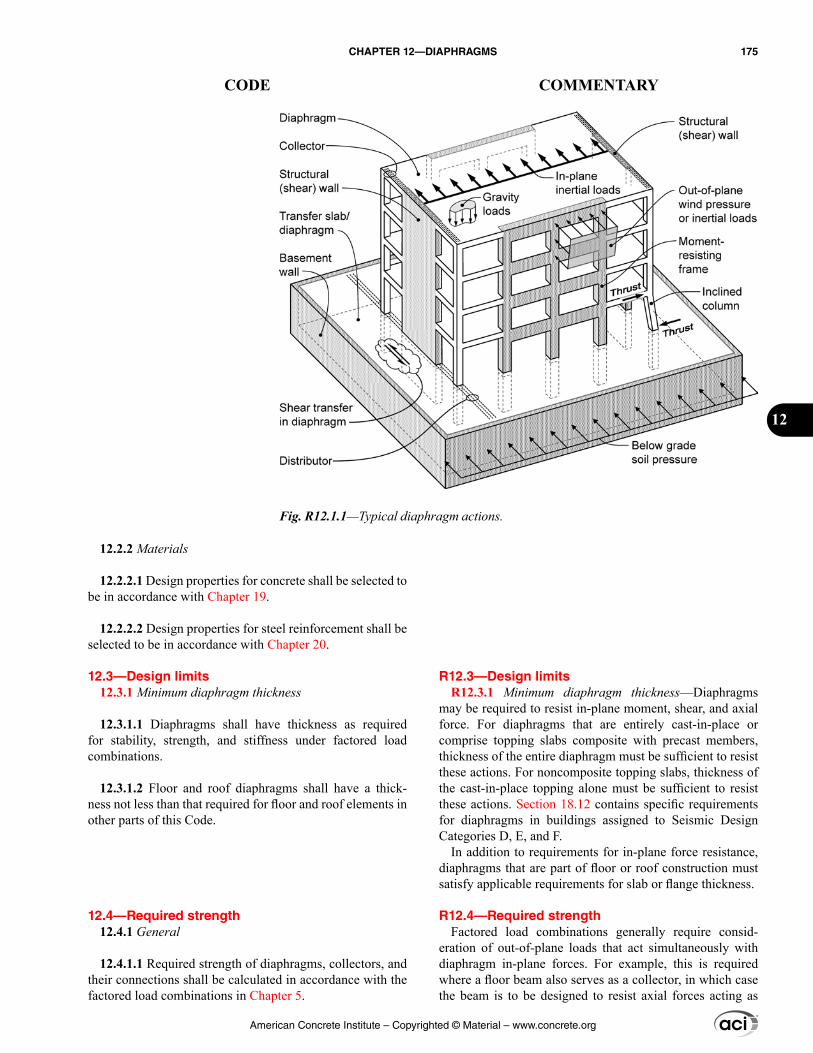
R12.3—Design limits R12.3.1 Minimum diaphragm thickness—Diaphragms
may be required to resist in-plane moment, shear, and axial force. For diaphragms that are entirely cast-in-place or comprise topping slabs composite with precast members, thickness of the entire diaphragm must be sufficient to resist these actions. For noncomposite topping slabs, thickness of the cast-in-place topping alone must be sufficient to resist these actions. Section 18.12 contains specific requirements for diaphragms in buildings assigned to Seismic Design Categories D, E, and F.
In addition to requirements for in-plane force resistance, diaphragms that are part of floor or roof construction must satisfy applicable requirements for slab or flange thickness.
R12.4—Required strength Factored load combinations generally require consid-
eration of out-of-plane loads that act simultaneously with diaphragm in-plane forces. For example, this is required where a floor beam also serves as a collector, in which case the beam is to be designed to resist axial forces acting as
12.2.2 Materials
12.2.2.1 Design properties for concrete shall be selected to be in accordance with Chapter 19.
12.2.2.2 Design properties for steel reinforcement shall be selected to be in accordance with Chapter 20.
12.3—Design limits 12.3.1 Minimum diaphragm thickness
12.3.1.1 Diaphragms shall have thickness as required for stability, strength, and stiffness under factored load combinations.
12.3.1.2 Floor and roof diaphragms shall have a thick-ness not less than that required for floor and roof elements in other parts of this Code.
12.4—Required strength 12.4.1 General
12.4.1.1 Required strength of diaphragms, collectors, and their connections shall be calculated in accordance with the factored load combinations in Chapter 5.
Fig. R12.1.1—Typical diaphragm actions.
American Concrete Institute – Copyrighted © Material – www.concrete.org
CHAPTER 12—DIAPHRAGMS 175
CODE COMMENTARY
12
a collector and bending moments acting as a floor beam supporting gravity loads.
R12.4.2 Diaphragm modeling and analysis
R12.4.2.1 ASCE/SEI 7 includes diaphragm modeling requirements for some design conditions, such as design to resist wind and earthquake loads. Where ASCE/SEI 7 is adopted as part of the general building code, those require-ments govern over provisions of this Code.
R12.4.2.2 Chapter 6 contains general requirements for analysis that are applicable to diaphragms. Diaphragms are usually designed to remain elastic or nearly elastic for forces acting within their plane under factored load combinations. Therefore, analysis methods satisfying theory of elastic analysis are generally acceptable. The provisions for elastic analysis in 6.6.1 through 6.6.3 can be applied.
Diaphragm in-plane stiffness affects not only the distri-bution of forces within the diaphragm, but also the distri-bution of displacements and forces among the vertical elements. Thus, the diaphragm stiffness model should be consistent with characteristics of the building. Where the diaphragm is very stiff compared to the vertical elements, as in a low aspect ratio, cast-in-place diaphragm supported by moment frames, it is acceptable to model the diaphragm as a completely rigid element. Where the diaphragm is flex-ible compared with the vertical elements, as in some jointed precast systems supported by structural walls, it may be acceptable to model the diaphragm as a flexible beam span-ning between rigid supports. In other cases, it may be advis-able to adopt a more detailed analytical model to account for the effects of diaphragm flexibility on the distribution of displacements and forces. Examples include buildings in which diaphragm and vertical element stiffnesses have approximately the same value, buildings with large force transfers, and parking structures in which ramps connect between floors and act essentially as bracing elements within the building.
For diaphragms constructed of concrete slabs, ASCE/SEI 7 permits the assumption of a rigid diaphragm if the diaphragm aspect ratio falls within a prescribed limit, which is different for wind and earthquake loads, and if the structure has no horizontal irregularities. ASCE/SEI 7 provisions do not prohibit the rigid diaphragm assumption for other condi-tions, provided the rigid diaphragm assumption is reasonably consistent with anticipated behavior. Cast-in-place concrete diaphragms designed with the rigid-diaphragm assumption have a long history of satisfactory performance even though they may fall outside the ASCE/SEI 7 index values.
R12.4.2.3 For low-aspect-ratio diaphragms that are entirely cast-in-place or comprise a cast-in-place topping slab on precast elements, the diaphragm is often modeled as a rigid element supported by flexible vertical elements. However,
12.4.1.2 Required strength of diaphragms that are part of floor or roof construction shall include effects of out-of-plane loads simultaneous with other applicable loads.
12.4.2 Diaphragm modeling and analysis
12.4.2.1 Diaphragm modeling and analysis requirements of the general building code shall govern where applicable. Otherwise, diaphragm modeling and analysis shall be in accordance with 12.4.2.2 through 12.4.2.4.
12.4.2.2 Modeling and analysis procedures shall satisfy requirements of Chapter 6.
12.4.2.3 Any set of reasonable and consistent assumptions for diaphragm stiffness shall be permitted.
American Concrete Institute – Copyrighted © Material – www.concrete.org
176 BUILDING CODE REQUIREMENTS FOR STRUCTURAL CONCRETE (ACI 318M-14) AND COMMENTARY (ACI 318RM-14)
CODE COMMENTARY
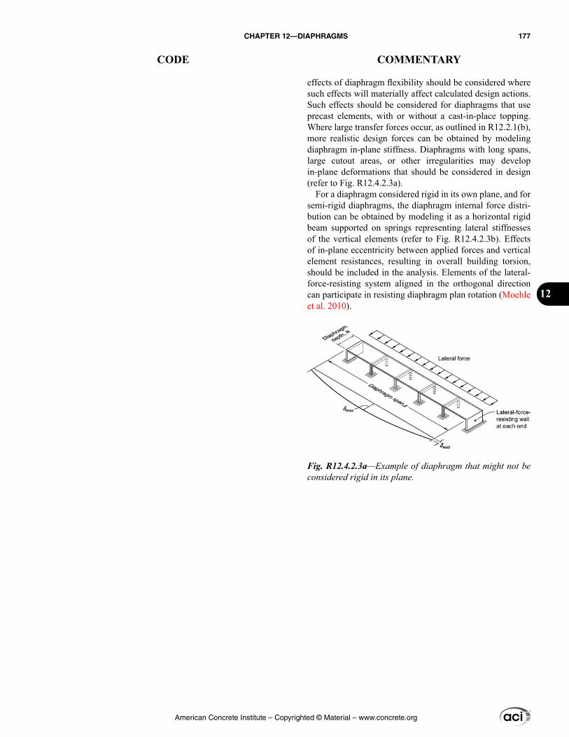
effects of diaphragm flexibility should be considered where such effects will materially affect calculated design actions. Such effects should be considered for diaphragms that use precast elements, with or without a cast-in-place topping. Where large transfer forces occur, as outlined in R12.2.1(b), more realistic design forces can be obtained by modeling diaphragm in-plane stiffness. Diaphragms with long spans, large cutout areas, or other irregularities may develop in-plane deformations that should be considered in design (refer to Fig. R12.4.2.3a).
For a diaphragm considered rigid in its own plane, and for semi-rigid diaphragms, the diaphragm internal force distri-bution can be obtained by modeling it as a horizontal rigid beam supported on springs representing lateral stiffnesses of the vertical elements (refer to Fig. R12.4.2.3b). Effects of in-plane eccentricity between applied forces and vertical element resistances, resulting in overall building torsion, should be included in the analysis. Elements of the lateral-force-resisting system aligned in the orthogonal direction can participate in resisting diaphragm plan rotation (Moehle et al. 2010).
Fig. R12.4.2.3a—Example of diaphragm that might not be considered rigid in its plane.
American Concrete Institute – Copyrighted © Material – www.concrete.org
CHAPTER 12—DIAPHRAGMS 177
CODE COMMENTARY
12
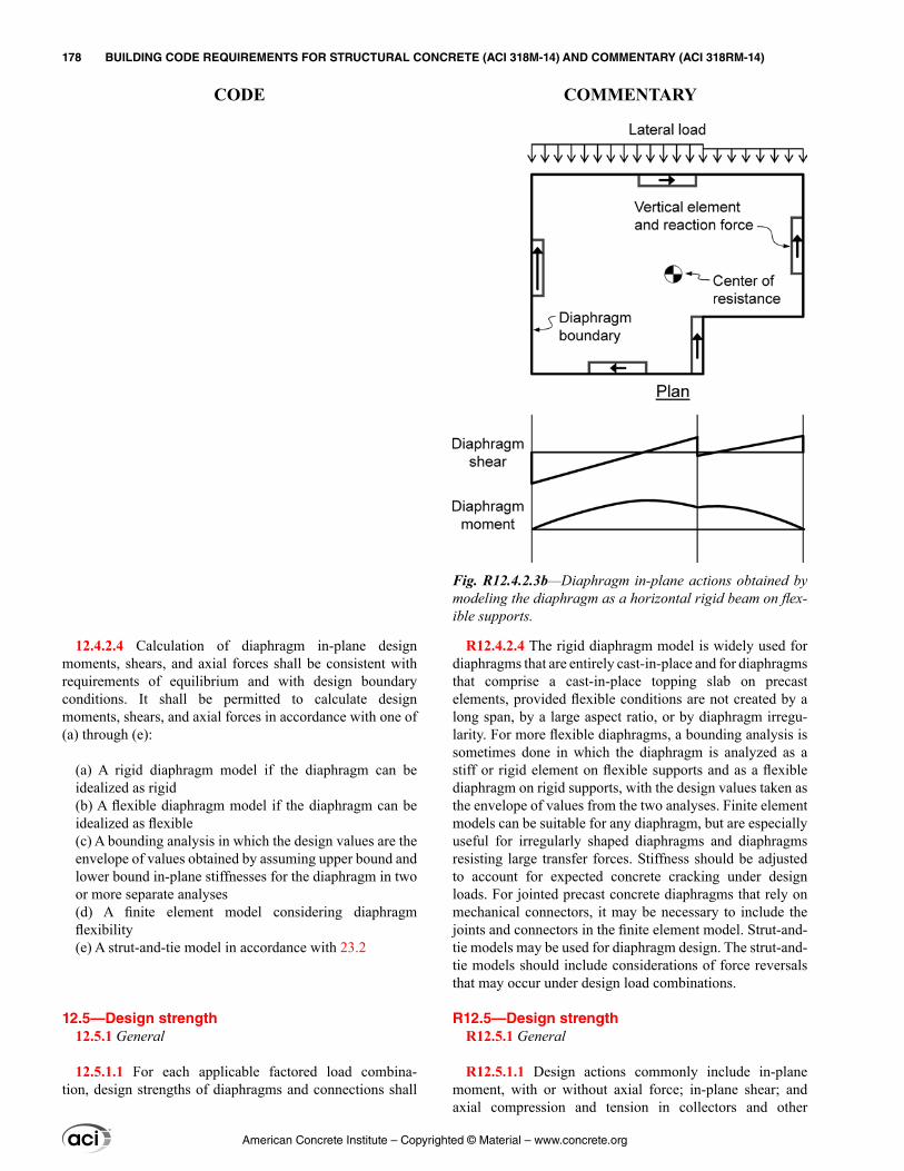
12.4.2.4 Calculation of diaphragm in-plane design moments, shears, and axial forces shall be consistent with requirements of equilibrium and with design boundary conditions. It shall be permitted to calculate design moments, shears, and axial forces in accordance with one of (a) through (e):
(a) A rigid diaphragm model if the diaphragm can be idealized as rigid(b) A flexible diaphragm model if the diaphragm can be idealized as flexible(c) A bounding analysis in which the design values are the envelope of values obtained by assuming upper bound and lower bound in-plane stiffnesses for the diaphragm in two or more separate analyses(d) A finite element model considering diaphragm flexibility(e) A strut-and-tie model in accordance with 23.2
12.5—Design strength 12.5.1 General
12.5.1.1 For each applicable factored load combina-tion, design strengths of diaphragms and connections shall
R12.4.2.4 The rigid diaphragm model is widely used for diaphragms that are entirely cast-in-place and for diaphragms that comprise a cast-in-place topping slab on precast elements, provided flexible conditions are not created by a long span, by a large aspect ratio, or by diaphragm irregu-larity. For more flexible diaphragms, a bounding analysis is sometimes done in which the diaphragm is analyzed as a stiff or rigid element on flexible supports and as a flexible diaphragm on rigid supports, with the design values taken as the envelope of values from the two analyses. Finite element models can be suitable for any diaphragm, but are especially useful for irregularly shaped diaphragms and diaphragms resisting large transfer forces. Stiffness should be adjusted to account for expected concrete cracking under design loads. For jointed precast concrete diaphragms that rely on mechanical connectors, it may be necessary to include the joints and connectors in the finite element model. Strut-and-tie models may be used for diaphragm design. The strut-and-tie models should include considerations of force reversals that may occur under design load combinations.
R12.5—Design strength R12.5.1 General
R12.5.1.1 Design actions commonly include in-plane moment, with or without axial force; in-plane shear; and axial compression and tension in collectors and other
Fig. R12.4.2.3b—Diaphragm in-plane actions obtained by modeling the diaphragm as a horizontal rigid beam on flex-ible supports.
American Concrete Institute – Copyrighted © Material – www.concrete.org
178 BUILDING CODE REQUIREMENTS FOR STRUCTURAL CONCRETE (ACI 318M-14) AND COMMENTARY (ACI 318RM-14)
CODE COMMENTARY
satisfy ϕSn ≥ U. Interaction between load effects shall be considered.
12.5.1.2 ϕ shall be determined in accordance with 21.2.
12.5.1.3 Design strengths shall be in accordance with (a), (b), (c), or (d):
(a) For a diaphragm idealized as a beam whose depth is equal to the full diaphragm depth, with moment resisted by boundary reinforcement concentrated at the diaphragm edges, design strengths shall be in accordance with 12.5.2 through 12.5.4.(b) For a diaphragm or a diaphragm segment modeled as a strut-and-tie system, design strengths shall be in accor-dance with 23.3.(c) For a diaphragm idealized with a finite-element model, design strengths shall be in accordance with Chapter 22. Nonuniform shear distributions shall be considered in design for shear. Collectors in such designs shall be provided to transfer diaphragm shears to the vertical elements of the lateral-force-resisting system.(d) For a diaphragm designed by alternative methods, such methods shall satisfy the requirements of equilibrium and shall provide design strengths at least equal to required strengths for all elements in the load path.
12.5.1.4 It shall be permitted to use precompression from prestressed reinforcement to resist diaphragm forces.
elements acting as struts or ties. Some diaphragm configura-tions may result in additional types of design actions. For example, a diaphragm vertical step can result in out-of-plane bending, torsion, or both. The diaphragm is required to be designed for such actions where they occur in elements that are part of the load path.
Nominal strengths are prescribed in Chapter 22 for a diaphragm idealized as a beam or solid element resisting in-plane moment, axial force, and shear; and in Chapter 23 for a diaphragm or diaphragm segment idealized as a strut-and-tie system. Collectors and struts around openings can be designed as compression members subjected to axial force using provisions of 10.5.2 with the strength reduction factor for compression-controlled members in 21.2.2. For axial tension in such members, nominal tensile strength is Asfy, and the strength reduction factor is 0.90 as required for tension-controlled members in 21.2.2.
Diaphragms are designed under load combinations of 5.3. Where a diaphragm or part of a diaphragm is subjected to multiple load effects, the interaction of the load effects is to be considered. A common example is where a collector is built within a beam or slab that also resists gravity loads, in which case the element is designed for combined moment and axial force. Another example is where a connection is subjected to simultaneous tension and shear.
R12.5.1.3 Different design strength requirements apply depending on how the diaphragm load-path is idealized.
Section 12.5.1.3(a) addresses requirements for the common case where a diaphragm is idealized as a beam spanning between supports and resisting forces within its plane, with chord reinforcement at the boundaries to resist in-plane moment and axial force. If diaphragms are designed according to this model, then it is appropriate to assume that shear flow is uniform through the diaphragm depth. Diaphragm depth refers to the dimension measured in the direction of lateral forces within the plane of the diaphragm (refer to Fig. R12.4.2.3a). If vertical elements of the lateral-force-resisting system do not extend the full depth of the diaphragm, then collectors are required to transfer shear acting along the remaining portions of the diaphragm depth to the vertical elements. Sections 12.5.2 through 12.5.4 are based on this model. This design approach is acceptable even if some of the moment is resisted by precompression as provided by 12.5.1.4.
Sections 12.5.1.3(b) through (d) permit alternative methods for design of diaphragms. If diaphragms are designed to resist moment through distributed chords, or if diaphragms are designed according to stress fields deter-mined by finite-element analysis, then non-uniform shear flow should be taken into account.
R12.5.1.4 In the typical case of a prestressed floor slab, prestressing is required, at a minimum, to resist the factored
American Concrete Institute – Copyrighted © Material – www.concrete.org
CHAPTER 12—DIAPHRAGMS 179
CODE COMMENTARY
12
12.5.1.5 If nonprestressed, bonded prestressing reinforce-ment is designed to resist collector forces, diaphragm shear, or tension due to in-plane moment, the value of steel stress used to calculate resistance shall not exceed the lesser of the specified yield strength and 420 MPa.
12.5.2 Moment and axial force
12.5.2.1 It shall be permitted to design a diaphragm to resist in-plane moment and axial force in accordance with 22.3 and 22.4.
12.5.2.2 It shall be permitted to resist tension due to moment by (a), (b), (c), or (d), or those methods in combination:
(a) Deformed bars conforming to 20.2.1(b) Strands or bars conforming to 20.3.1, either prestressed or nonprestressed(c) Mechanical connectors crossing joints between precast elements(d) Precompression from prestressed reinforcement
12.5.2.3 Nonprestressed reinforcement and mechanical connectors resisting tension due to moment shall be located within h/4 of the tension edge of the diaphragm, where h is diaphragm depth measured in the plane of the diaphragm at that location. Where diaphragm depth changes along the span, it shall be permitted to develop reinforcement into adjacent diaphragm segments that are not within the h/4 limit.
load combination 1.2D + 1.6L, where L may have been reduced as permitted by the general building code. For wind or earthquake design, however, the gravity load to be resisted by prestressing is reduced because the governing load combination is 1.2D + f1L + (W or E), where f1 is either 1.0 or 0.5 depending on the nature of L. Thus, only a portion of the effective prestress is required to resist the reduced gravity loads. The remainder of the effective prestress can be used to resist in-plane diaphragm moments. Additional moment, if any, is resisted by added reinforcement.
R12.5.1.5 Nonprestressed bonded prestressing rein-forcement, either strand or bars, is sometimes used to resist diaphragm design forces. The imposed limit on assumed yield strength is to control crack width and joint opening. The Code does not include provisions for developing nonprestressed, bonded prestressing reinforcement. Stress limits for other provided reinforcement are prescribed in Chapter 20.
R12.5.2 Moment and axial force
R12.5.2.1 This section permits design for moment and axial force in accordance with the usual assumptions of 22.3 and 22.4, including the assumption that strains vary linearly through the depth of the diaphragm. In most cases, design for moment and axial force can be accomplished satisfacto-rily using an approximate tension-compression couple with the strength reduction factor equal to 0.90.
R12.5.2.2 Bonded prestressing reinforcement used to resist in-plane moment and axial force can be either prestressed or nonprestressed. Mechanical connectors crossing joints between precast concrete elements are provided to complete a continuous load path for reinforcement embedded in those elements. The use of precompression from prestressed rein-forcement is discussed in R12.5.1.4.
R12.5.2.3 Figure R12.5.2.3 illustrates permitted locations of nonprestressed reinforcement resisting tension due to moment and axial force. Where diaphragm depth changes along the span, it is permitted to develop tension reinforce-ment in adjacent sections even if the reinforcement falls outside the h/4 limit of the adjacent section. In such cases, strut-and-tie models or elastic plane stress analysis can be used to determine bar extensions and other reinforcement requirements to provide continuity across the step. The restriction on location of nonprestressed reinforcement and mechanical connectors is intended to control cracking and excessive joint opening that might occur near the edges if reinforcement or mechanical connectors were distributed throughout the diaphragm depth. The concentration of flex-ural tension reinforcement near the edge of the diaphragm also results in more uniform shear flow through the depth of the diaphragm.
American Concrete Institute – Copyrighted © Material – www.concrete.org
180 BUILDING CODE REQUIREMENTS FOR STRUCTURAL CONCRETE (ACI 318M-14) AND COMMENTARY (ACI 318RM-14)
CODE COMMENTARY
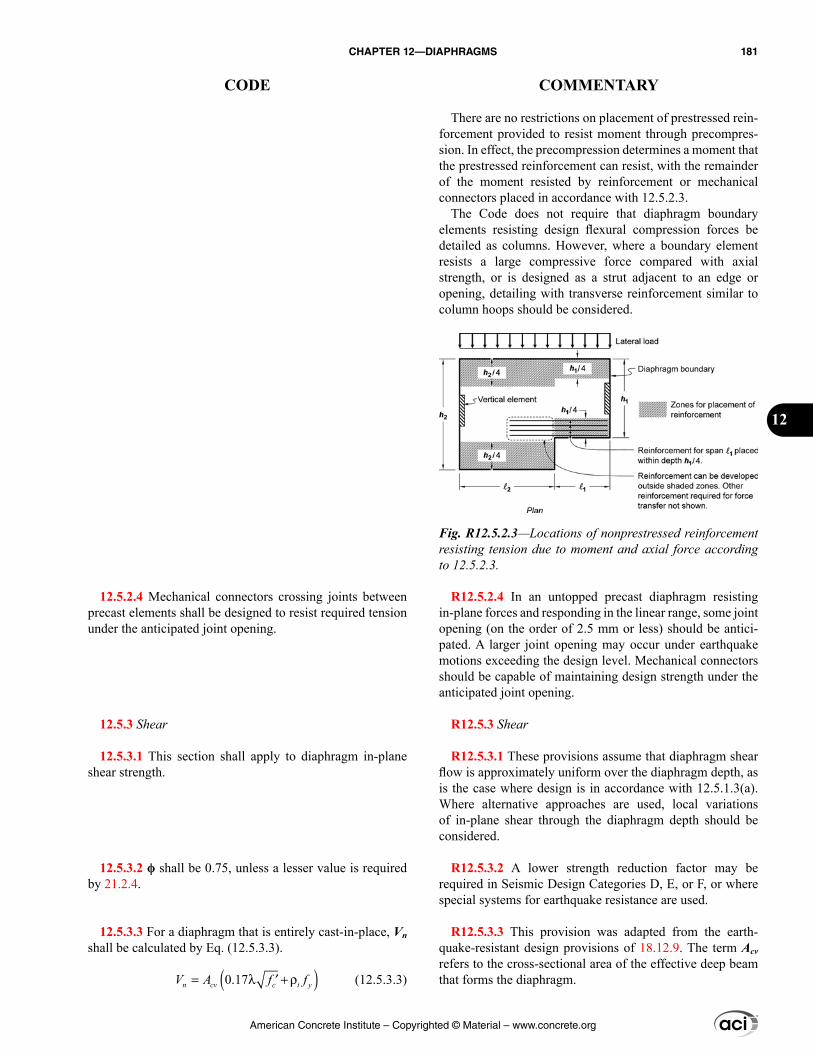
12.5.2.4 Mechanical connectors crossing joints between precast elements shall be designed to resist required tension under the anticipated joint opening.
12.5.3 Shear
12.5.3.1 This section shall apply to diaphragm in-plane shear strength.
12.5.3.2 ϕ shall be 0.75, unless a lesser value is required by 21.2.4.
12.5.3.3 For a diaphragm that is entirely cast-in-place, Vn shall be calculated by Eq. (12.5.3.3).
( )0.17 ′= λ + ρn cv t ycfV A f (12.5.3.3)
There are no restrictions on placement of prestressed rein-forcement provided to resist moment through precompres-sion. In effect, the precompression determines a moment that the prestressed reinforcement can resist, with the remainder of the moment resisted by reinforcement or mechanical connectors placed in accordance with 12.5.2.3.
The Code does not require that diaphragm boundary elements resisting design flexural compression forces be detailed as columns. However, where a boundary element resists a large compressive force compared with axial strength, or is designed as a strut adjacent to an edge or opening, detailing with transverse reinforcement similar to column hoops should be considered.
R12.5.2.4 In an untopped precast diaphragm resisting in-plane forces and responding in the linear range, some joint opening (on the order of 2.5 mm or less) should be antici-pated. A larger joint opening may occur under earthquake motions exceeding the design level. Mechanical connectors should be capable of maintaining design strength under the anticipated joint opening.
R12.5.3 Shear
R12.5.3.1 These provisions assume that diaphragm shear flow is approximately uniform over the diaphragm depth, as is the case where design is in accordance with 12.5.1.3(a). Where alternative approaches are used, local variations of in-plane shear through the diaphragm depth should be considered.
R12.5.3.2 A lower strength reduction factor may be required in Seismic Design Categories D, E, or F, or where special systems for earthquake resistance are used.
R12.5.3.3 This provision was adapted from the earth-quake-resistant design provisions of 18.12.9. The term Acv refers to the cross-sectional area of the effective deep beam that forms the diaphragm.
Fig. R12.5.2.3—Locations of nonprestressed reinforcement resisting tension due to moment and axial force according to 12.5.2.3.
American Concrete Institute – Copyrighted © Material – www.concrete.org
CHAPTER 12—DIAPHRAGMS 181
CODE COMMENTARY
12
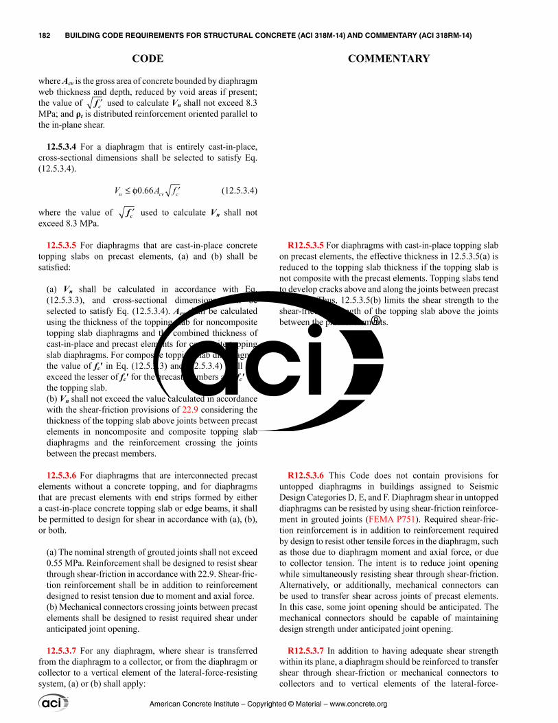
where Acv is the gross area of concrete bounded by diaphragm web thickness and depth, reduced by void areas if present; the value of ′fc used to calculate Vn shall not exceed 8.3 MPa; and ρt is distributed reinforcement oriented parallel to the in-plane shear.
12.5.3.4 For a diaphragm that is entirely cast-in-place, cross-sectional dimensions shall be selected to satisfy Eq. (12.5.3.4).
0.66≤ φ ′u c cvV A f (12.5.3.4)
where the value of ′fc used to calculate Vn shall not exceed 8.3 MPa.
12.5.3.5 For diaphragms that are cast-in-place concrete topping slabs on precast elements, (a) and (b) shall be satisfied:
(a) Vn shall be calculated in accordance with Eq. (12.5.3.3), and cross-sectional dimensions shall be selected to satisfy Eq. (12.5.3.4). Acv shall be calculated using the thickness of the topping slab for noncomposite topping slab diaphragms and the combined thickness of cast-in-place and precast elements for composite topping slab diaphragms. For composite topping slab diaphragms, the value of fc′ in Eq. (12.5.3.3) and (12.5.3.4) shall not exceed the lesser of fc′ for the precast members and fc′ for the topping slab.(b) Vn shall not exceed the value calculated in accordance with the shear-friction provisions of 22.9 considering the thickness of the topping slab above joints between precast elements in noncomposite and composite topping slab diaphragms and the reinforcement crossing the joints between the precast members.
12.5.3.6 For diaphragms that are interconnected precast elements without a concrete topping, and for diaphragms that are precast elements with end strips formed by either a cast-in-place concrete topping slab or edge beams, it shall be permitted to design for shear in accordance with (a), (b), or both.
(a) The nominal strength of grouted joints shall not exceed 0.55 MPa. Reinforcement shall be designed to resist shear through shear-friction in accordance with 22.9. Shear-fric-tion reinforcement shall be in addition to reinforcement designed to resist tension due to moment and axial force.(b) Mechanical connectors crossing joints between precast elements shall be designed to resist required shear under anticipated joint opening.
12.5.3.7 For any diaphragm, where shear is transferred from the diaphragm to a collector, or from the diaphragm or collector to a vertical element of the lateral-force-resisting system, (a) or (b) shall apply:
R12.5.3.5 For diaphragms with cast-in-place topping slab on precast elements, the effective thickness in 12.5.3.5(a) is reduced to the topping slab thickness if the topping slab is not composite with the precast elements. Topping slabs tend to develop cracks above and along the joints between precast elements. Thus, 12.5.3.5(b) limits the shear strength to the shear-friction strength of the topping slab above the joints between the precast elements.
R12.5.3.6 This Code does not contain provisions for untopped diaphragms in buildings assigned to Seismic Design Categories D, E, and F. Diaphragm shear in untopped diaphragms can be resisted by using shear-friction reinforce-ment in grouted joints (FEMA P751). Required shear-fric-tion reinforcement is in addition to reinforcement required by design to resist other tensile forces in the diaphragm, such as those due to diaphragm moment and axial force, or due to collector tension. The intent is to reduce joint opening while simultaneously resisting shear through shear-friction. Alternatively, or additionally, mechanical connectors can be used to transfer shear across joints of precast elements. In this case, some joint opening should be anticipated. The mechanical connectors should be capable of maintaining design strength under anticipated joint opening.
R12.5.3.7 In addition to having adequate shear strength within its plane, a diaphragm should be reinforced to transfer shear through shear-friction or mechanical connectors to collectors and to vertical elements of the lateral-force-
American Concrete Institute – Copyrighted © Material – www.concrete.org
182 BUILDING CODE REQUIREMENTS FOR STRUCTURAL CONCRETE (ACI 318M-14) AND COMMENTARY (ACI 318RM-14)
CODE COMMENTARY
resisting system. In diaphragms that are entirely cast-in-place, reinforcement provided for other purposes usually is adequate to transfer force from the diaphragm into the collectors through shear-friction. However, additional rein-forcement may be required to transfer diaphragm or collector shear into vertical elements of the lateral-force-resisting system through shear-friction. Figure R12.5.3.7 illustrates a common detail of dowels provided for this purpose.
R12.5.4 Collectors—A collector is a region of a diaphragm that transfers forces between the diaphragm and a vertical element of the lateral-force-resisting system. A collector can extend transversely into the diaphragm to reduce nominal stresses and reinforcement congestion, as shown in Fig. R12.5.3.7. Where a collector width extends into the slab, the collector width on each side of the vertical element should not exceed approximately one-half the contact length between the collector and the vertical element.
R12.5.4.1 The design procedure in 12.5.1.3(a) models the diaphragm as a full-depth beam with uniform shear flow. If vertical elements of the lateral-force-resisting system do not extend the full depth of the diaphragm, then collectors are required to transfer shear acting along the remaining portions of the diaphragm depth to the vertical element, as shown in Fig. R12.5.4.1. Partial-depth collectors can also be consid-ered, but a complete force path should be designed that is capable of transmitting all forces from the diaphragm to the collector and into the vertical elements (Moehle et al. 2010).
(a) Where shear is transferred through concrete, the shear-friction provisions of 22.9 shall be satisfied.(b) Where shear is transferred through mechanical connectors or dowels, effects of uplift and rotation of the vertical element of the lateral-force-resisting system shall be considered.
12.5.4 Collectors
12.5.4.1 Collectors shall extend from the vertical elements of the lateral-force-resisting system across all or part of the diaphragm depth as required to transfer shear from the diaphragm to the vertical element. It shall be permitted to discontinue a collector along lengths of vertical elements of the lateral-force-resisting system where transfer of design collector forces is not required.
Fig. R12.5.3.7—Typical detail showing dowels provided for shear transfer to a structural wall through shear-friction.
American Concrete Institute – Copyrighted © Material – www.concrete.org
CHAPTER 12—DIAPHRAGMS 183
CODE COMMENTARY
12
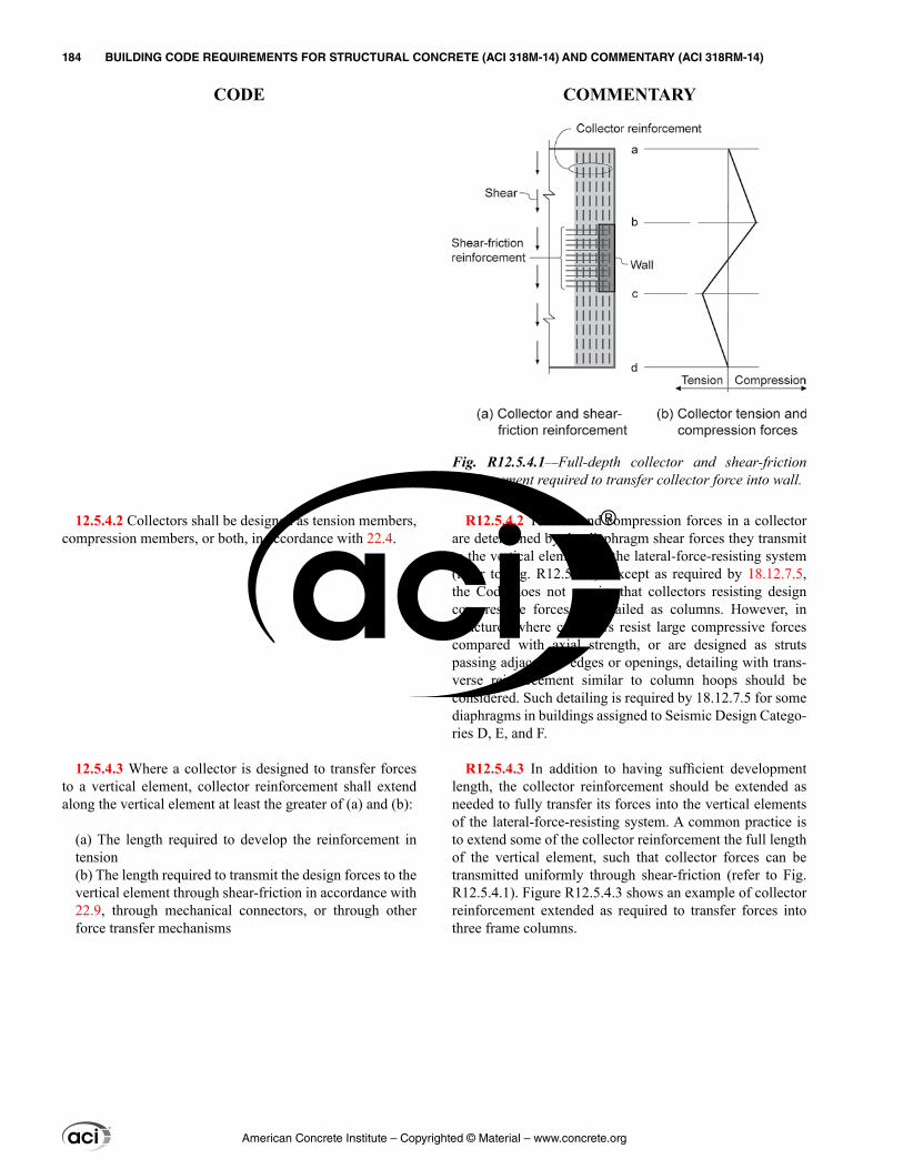
R12.5.4.2 Tension and compression forces in a collector are determined by the diaphragm shear forces they transmit to the vertical elements of the lateral-force-resisting system (refer to Fig. R12.5.4.1). Except as required by 18.12.7.5, the Code does not require that collectors resisting design compressive forces be detailed as columns. However, in structures where collectors resist large compressive forces compared with axial strength, or are designed as struts passing adjacent to edges or openings, detailing with trans-verse reinforcement similar to column hoops should be considered. Such detailing is required by 18.12.7.5 for some diaphragms in buildings assigned to Seismic Design Catego-ries D, E, and F.
R12.5.4.3 In addition to having sufficient development length, the collector reinforcement should be extended as needed to fully transfer its forces into the vertical elements of the lateral-force-resisting system. A common practice is to extend some of the collector reinforcement the full length of the vertical element, such that collector forces can be transmitted uniformly through shear-friction (refer to Fig. R12.5.4.1). Figure R12.5.4.3 shows an example of collector reinforcement extended as required to transfer forces into three frame columns.
12.5.4.2 Collectors shall be designed as tension members, compression members, or both, in accordance with 22.4.
12.5.4.3 Where a collector is designed to transfer forces to a vertical element, collector reinforcement shall extend along the vertical element at least the greater of (a) and (b):
(a) The length required to develop the reinforcement in tension(b) The length required to transmit the design forces to the vertical element through shear-friction in accordance with 22.9, through mechanical connectors, or through other force transfer mechanisms
Fig. R12.5.4.1—Full-depth collector and shear-friction reinforcement required to transfer collector force into wall.
American Concrete Institute – Copyrighted © Material – www.concrete.org
184 BUILDING CODE REQUIREMENTS FOR STRUCTURAL CONCRETE (ACI 318M-14) AND COMMENTARY (ACI 318RM-14)
CODE COMMENTARY
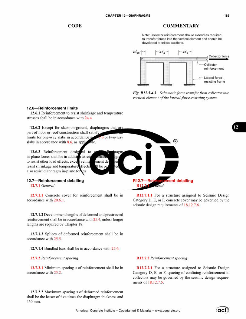
R12.7—Reinforcement detailing R12.7.1 General
R12.7.1.1 For a structure assigned to Seismic Design Category D, E, or F, concrete cover may be governed by the seismic design requirements of 18.12.7.6.
R12.7.2 Reinforcement spacing
R12.7.2.1 For a structure assigned to Seismic Design Category D, E, or F, spacing of confining reinforcement in collectors may be governed by the seismic design require-ments of 18.12.7.5.
12.6—Reinforcement limits 12.6.1 Reinforcement to resist shrinkage and temperature
stresses shall be in accordance with 24.4.
12.6.2 Except for slabs-on-ground, diaphragms that are part of floor or roof construction shall satisfy reinforcement limits for one-way slabs in accordance with 7.6 or two-way slabs in accordance with 8.6, as applicable.
12.6.3 Reinforcement designed to resist diaphragm in-plane forces shall be in addition to reinforcement designed to resist other load effects, except reinforcement designed to resist shrinkage and temperature effects shall be permitted to also resist diaphragm in-plane forces
12.7—Reinforcement detailing 12.7.1 General
12.7.1.1 Concrete cover for reinforcement shall be in accordance with 20.6.1.
12.7.1.2 Development lengths of deformed and prestressed reinforcement shall be in accordance with 25.4, unless longer lengths are required by Chapter 18.
12.7.1.3 Splices of deformed reinforcement shall be in accordance with 25.5.
12.7.1.4 Bundled bars shall be in accordance with 25.6.
12.7.2 Reinforcement spacing
12.7.2.1 Minimum spacing s of reinforcement shall be in accordance with 25.2.
12.7.2.2 Maximum spacing s of deformed reinforcement shall be the lesser of five times the diaphragm thickness and 450 mm.
Fig. R12.5.4.3—Schematic force transfer from collector into vertical element of the lateral-force-resisting system.
American Concrete Institute – Copyrighted © Material – www.concrete.org
CHAPTER 12—DIAPHRAGMS 185
CODE COMMENTARY
12
R12.7.3 Diaphragm and collector reinforcement
R12.7.3.2 Critical sections for development of reinforce-ment generally are at points of maximum stress, at points where adjacent terminated reinforcement is no longer required to resist design forces, and at other points of discon-tinuity in the diaphragm.
R12.7.3.3 For a beam, the Code requires flexural rein-forcement to extend the greater of d and 12db past points where it is no longer required for flexure. These extensions are important for a beam to protect against development or shear failure that could result from inaccuracies in calculated locations of tensile stress. Similar failures in diaphragms have not been reported. To simplify design and avoid exces-sively long bar extensions that could result if the beam provisions were applied to diaphragms, this provision only requires that tension reinforcement extend ℓd beyond points where it is no longer required to resist tension.
12.7.3 Diaphragm and collector reinforcement
12.7.3.1 Except for slabs-on-ground, diaphragms that are part of floor or roof construction shall satisfy reinforce-ment detailing of one-way slabs in accordance with 7.7 or two-way slabs in accordance with 8.7, as applicable.
12.7.3.2 Calculated tensile or compressive force in rein-forcement at each section of the diaphragm or collector shall be developed on each side of that section.
12.7.3.3 Reinforcement provided to resist tension shall extend beyond the point at which it is no longer required to resist tension at least ℓd, except at diaphragm edges and at expansion joints.
American Concrete Institute – Copyrighted © Material – www.concrete.org
186 BUILDING CODE REQUIREMENTS FOR STRUCTURAL CONCRETE (ACI 318M-14) AND COMMENTARY (ACI 318RM-14)
CODE COMMENTARY
CHAPTER 13—FOUNDATIONS
13.1—Scope
13.1.1 This chapter shall apply to the design of nonpre-stressed and prestressed foundations, including shallow foundations (a) through (e) and, where applicable, deep foundations (f) through (i):
(a) Strip footings(b) Isolated footings(c) Combined footings(d) Mat foundations(e) Grade beams(f) Pile caps(g) Piles(h) Drilled piers(i) Caissons
R13—FOUNDATIONS
R13.1—Scope While requirements applicable to foundations are provided
in this chapter, the majority of requirements used for founda-tion design are found in other chapters of the Code. These other chapters are referenced in Chapter 13. However, the applicability of the specific provisions within these other chapters may not be explicitly defined for foundations.
R13.1.1 Examples of foundation types covered by this chapter are illustrated in Fig. R13.1.1. Stepped and sloped footings are considered to be subsets of other footing types.
American Concrete Institute – Copyrighted © Material – www.concrete.org
CHAPTER 13—FOUNDATIONS 187
CODE COMMENTARY
13
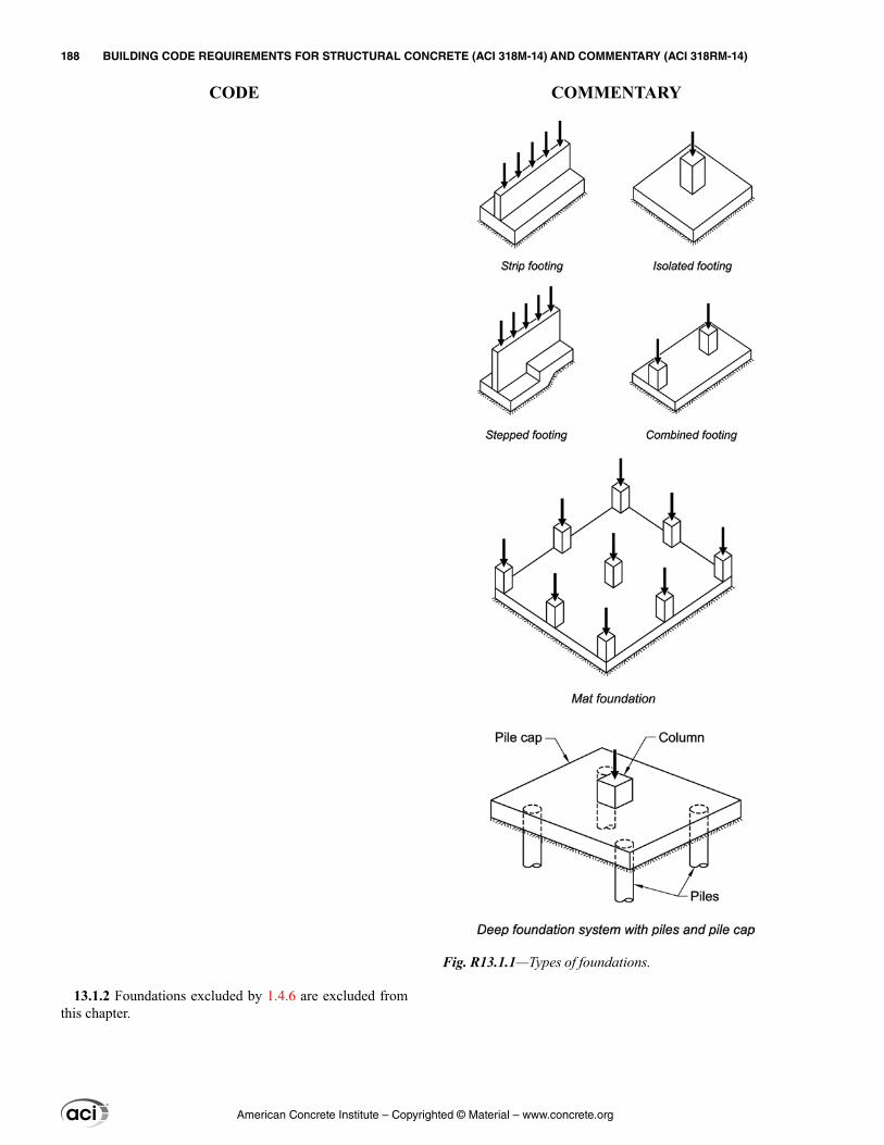
13.1.2 Foundations excluded by 1.4.6 are excluded from this chapter.
Fig. R13.1.1—Types of foundations.
American Concrete Institute – Copyrighted © Material – www.concrete.org
188 BUILDING CODE REQUIREMENTS FOR STRUCTURAL CONCRETE (ACI 318M-14) AND COMMENTARY (ACI 318RM-14)
CODE COMMENTARY
R13.2—General
R13.2.3 Earthquake effects
R13.2.3.1 The base of a structure, as defined in analysis, does not necessarily correspond to the foundation or ground level, or to the base of a building as defined in the general building code for planning (for example, for height limits or fire protection requirements). Details of columns and walls extending below the base of a structure to the foundation are required to be consistent with those above the base of the structure.
R13.2.3.2 It is desirable that inelastic response in strong ground shaking occurs in structural elements above the foundations, and that the elements of the foundations remain essentially elastic; repairs to foundations can be extremely difficult and expensive. The requirements for foundations supporting buildings assigned to Seismic Design Category (SDC) D, E, or F represent a consensus of a minimum level of good practice in designing and detailing concrete founda-tions to achieve this goal.
R13.2.4 Slabs-on-ground—Slabs-on-ground often act as a diaphragm to hold the building together at the ground level and minimize the effects of out-of-phase ground motion that may occur over the footprint of the building. In these cases, the slab-on-ground should be adequately reinforced and detailed. As required in Chapter 26, construction documents should clearly state that these slabs-on-ground are structural members so as to prohibit sawcutting of such slabs.
13.2—General 13.2.1 Materials
13.2.1.1 Design properties for concrete shall be selected to be in accordance with Chapter 19.
13.2.1.2 Design properties for steel reinforcement shall be selected to be in accordance with Chapter 20.
13.2.1.3 Materials, design, and detailing requirements for embedments in concrete shall be in accordance with 20.7.
13.2.2 Connection to other members
13.2.2.1 Design and detailing of cast-in-place and precast column, pedestal, and wall connections to foundations shall be in accordance with 16.3.
13.2.3 Earthquake effects
13.2.3.1 Structural members extending below the base of the structure that are required to transmit forces resulting from earthquake effects to the foundation shall be designed in accordance with 18.2.2.3.
13.2.3.2 For structures assigned to Seismic Design Category (SDC) D, E, or F, shallow and deep foundations resisting earthquake-induced forces or transferring earth-quake-induced forces between structure and ground shall be designed in accordance with 18.13.
13.2.4 Slabs-on-ground
13.2.4.1 Slabs-on-ground that transmit vertical loads or lateral forces from other parts of the structure to the ground shall be designed and detailed in accordance with applicable provisions of this Code.
13.2.4.2 Slabs-on-ground that transmit lateral forces as part of the seismic-force-resisting system shall be designed in accordance with 18.13.
13.2.5 Plain concrete
13.2.5.1 Plain concrete foundations shall be designed in accordance with Chapter 14.
American Concrete Institute – Copyrighted © Material – www.concrete.org
CHAPTER 13—FOUNDATIONS 189
CODE COMMENTARY
13
R13.2.6 Design criteria
R13.2.6.1 Permissible soil pressures or permissible pile capacities are determined by principles of soil mechanics and in accordance with the general building code. The size of the base area of a footing on soil or the number and arrangement of piles are usually established on the basis of these permissible values and unfactored applied (service) loads, such as D, L, W, and E, in whatever combination that governs the design. In cases in which eccentric loads or moments are to be considered, the extreme soil pressure or pile reaction obtained from this loading should be within the permissible values. The resultant reactions due to service loads combined with moments, shears, or both, caused by wind or earthquake forces should not exceed the increased values that may be permitted by the general building code.
To proportion a footing or pile cap for strength, it is neces-sary to calculate the contact soil pressure or pile reaction due to the applied factored load. These calculated soil pressures or pile reactions are used to determine the required strength of the foundation for flexure, shear, and development of reinforcement, as in any other member of the structure. In the case of eccentric loading, applied factored loads may cause patterns of soil pressures and pile reactions that are different from those obtained by unfactored loads.
Only the calculated end moments at the base of a column or pedestal require transfer to the footing. The minimum moment requirement for slenderness considerations given in 6.6.4.5 need not be considered for transfer of forces and moments to footings.
R13.2.6.2 Foundation design is permitted to be based directly on fundamental principles of structural mechanics, provided it can be demonstrated that all strength and service-ability criteria are satisfied. Design of the foundation may be achieved through the use of classic solutions based on a linearly elastic continuum, numerical solutions based on discrete elements, or yield-line analyses. In all cases, anal-yses and evaluation of the stress conditions at points of load application or pile reactions in relation to shear and torsion, as well as flexure, should be included.
R13.2.6.3 An example of the application of this provision is a pile cap supported on piles, similar to that shown in Fig. R13.1.1, which can be designed using a three-dimensional strut-and-tie model satisfying Chapter 23 (Adebar et al. 1990).
R13.2.7 Critical sections for shallow foundations and pile caps
13.2.6 Design criteria
13.2.6.1 Foundations shall be proportioned to resist factored loads and induced reactions.
13.2.6.2 Foundation systems shall be permitted to be designed by any procedure satisfying equilibrium and geometric compatibility.
13.2.6.3 Foundation design in accordance with strut-and-tie modeling, Chapter 23, shall be permitted.
13.2.6.4 External moment on any section of a strip footing, isolated footing, or pile cap shall be calculated by passing a vertical plane through the member and calculating the moment of the forces acting over the entire area of member on one side of that vertical plane.
13.2.7 Critical sections for shallow foundations and pile caps
American Concrete Institute – Copyrighted © Material – www.concrete.org
190 BUILDING CODE REQUIREMENTS FOR STRUCTURAL CONCRETE (ACI 318M-14) AND COMMENTARY (ACI 318RM-14)
CODE COMMENTARY
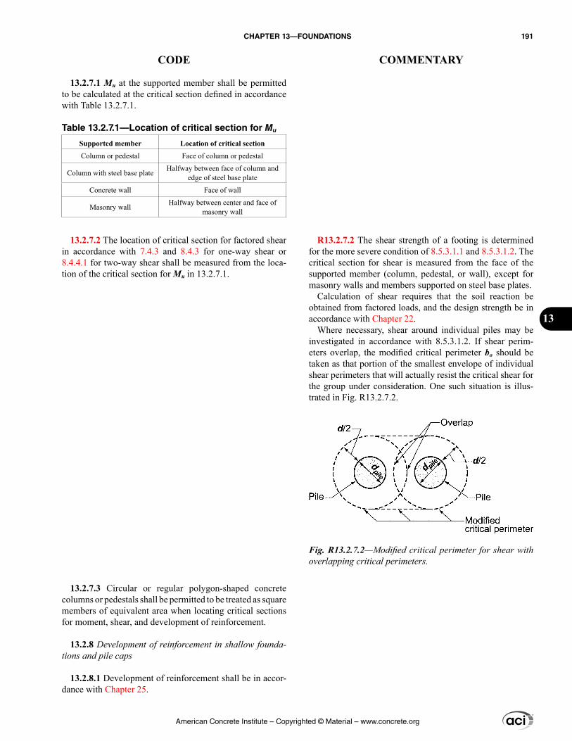
R13.2.7.2 The shear strength of a footing is determined for the more severe condition of 8.5.3.1.1 and 8.5.3.1.2. The critical section for shear is measured from the face of the supported member (column, pedestal, or wall), except for masonry walls and members supported on steel base plates.
Calculation of shear requires that the soil reaction be obtained from factored loads, and the design strength be in accordance with Chapter 22.
Where necessary, shear around individual piles may be investigated in accordance with 8.5.3.1.2. If shear perim-eters overlap, the modified critical perimeter bo should be taken as that portion of the smallest envelope of individual shear perimeters that will actually resist the critical shear for the group under consideration. One such situation is illus-trated in Fig. R13.2.7.2.
13.2.7.1 Mu at the supported member shall be permitted to be calculated at the critical section defined in accordance with Table 13.2.7.1.
Table 13.2.7.1—Location of critical section for Mu
Supported member Location of critical section
Column or pedestal Face of column or pedestal
Column with steel base plate Halfway between face of column and edge of steel base plate
Concrete wall Face of wall
Masonry wall Halfway between center and face of masonry wall
13.2.7.2 The location of critical section for factored shear in accordance with 7.4.3 and 8.4.3 for one-way shear or 8.4.4.1 for two-way shear shall be measured from the loca-tion of the critical section for Mu in 13.2.7.1.
13.2.7.3 Circular or regular polygon-shaped concrete columns or pedestals shall be permitted to be treated as square members of equivalent area when locating critical sections for moment, shear, and development of reinforcement.
13.2.8 Development of reinforcement in shallow founda-tions and pile caps
13.2.8.1 Development of reinforcement shall be in accor-dance with Chapter 25.
Fig. R13.2.7.2—Modified critical perimeter for shear with overlapping critical perimeters.
American Concrete Institute – Copyrighted © Material – www.concrete.org
CHAPTER 13—FOUNDATIONS 191
CODE COMMENTARY
13
13.2.8.2 Calculated tensile or compressive force in rein-forcement at each section shall be developed on each side of that section.
13.2.8.3 Critical sections for development of reinforcement shall be assumed at the same locations as given in 13.2.7.1 for maximum factored moment and at all other vertical planes where changes of section or reinforcement occur.
13.2.8.4 Adequate anchorage shall be provided for tension reinforcement where reinforcement stress is not directly proportional to moment, such as in sloped, stepped, or tapered foundations; or where tension reinforcement is not parallel to the compression face.
13.3—Shallow foundations 13.3.1 General
13.3.1.1 Minimum base area of foundation shall be calcu-lated from unfactored forces and moments transmitted by foundation to soil or rock and permissible bearing pressure selected through principles of soil or rock mechanics.
13.3.1.2 Overall depth of foundation shall be selected such that the effective depth of bottom reinforcement is at least 150 mm.
13.3.1.3 In sloped, stepped, or tapered foundations, depth and location of steps or angle of slope shall be such that design requirements are satisfied at every section.
13.3.2 One-way shallow foundations
13.3.2.1 The design and detailing of one-way shallow foundations, including strip footings, combined footings, and grade beams, shall be in accordance with this section and the applicable provisions of Chapter 7 and Chapter 9.
13.3.2.2 Reinforcement shall be distributed uniformly across entire width of one-way footings.
13.3.3 Two-way isolated footings
13.3.3.1 The design and detailing of two-way isolated footings shall be in accordance with this section and the applicable provisions of Chapter 7 and Chapter 8.
13.3.3.2 In square two-way footings, reinforcement shall be distributed uniformly across entire width of footing in both directions.
13.3.3.3 In rectangular footings, reinforcement shall be distributed in accordance with (a) and (b):
(a) Reinforcement in the long direction shall be distributed uniformly across entire width of footing.
R13.3—Shallow foundations R13.3.1 General
R13.3.1.1 General discussion on the sizing of shallow foundations is provided in R13.2.6.1.
R13.3.1.3 Anchorage of reinforcement in sloped, stepped, or tapered foundations is addressed in 13.2.8.4.
R13.3.3 Two-way isolated footings
R13.3.3.3 To minimize potential construction errors in placing bars, a common practice is to increase the amount of reinforcement in the short direction by 2β/(β + 1) and space it uniformly along the long dimension of the footing (CRSI Handbook 1984; Fling 1987).
American Concrete Institute – Copyrighted © Material – www.concrete.org
192 BUILDING CODE REQUIREMENTS FOR STRUCTURAL CONCRETE (ACI 318M-14) AND COMMENTARY (ACI 318RM-14)
CODE COMMENTARY
(b) For reinforcement in the short direction, a portion of the total reinforcement, γsAs, shall be distributed uniformly over a band width equal to the length of short side of footing, centered on centerline of column or pedestal. Remainder of reinforcement required in the short direc-tion, (1 – γs)As, shall be distributed uniformly outside the center band width of footing, where γs is calculated by:
( )2
1sγ =β +
(13.3.3.3)
where β is the ratio of long to short side of footing.
13.3.4 Two-way combined footings and mat foundations
13.3.4.1 The design and detailing of combined footings and mat foundations shall be in accordance with this section and the applicable provisions of Chapter 8.
13.3.4.2 The direct design method of 8.10 shall not be used to design combined footings and mat foundations.
13.3.4.3 Distribution of bearing pressure under combined footings and mat foundations shall be consistent with prop-erties of the soil or rock and the structure, and with estab-lished principles of soil or rock mechanics.
13.3.4.4 Minimum reinforcement in nonprestressed mat foundations shall be in accordance with 8.6.1.1.
13.3.5 Walls as grade beams
13.3.5.1 The design of walls as grade beams shall be in accordance with the applicable provisions of Chapter 9.
13.3.5.2 If a grade beam wall is considered a deep beam in accordance with 9.9.1.1, design shall satisfy the require-ments of 9.9.
13.3.5.3 Grade beam walls shall satisfy the minimum rein-forcement requirements of 11.6.
13.4—Deep foundations 13.4.1 General
13.4.1.1 Number and arrangement of piles, drilled piers, and caissons shall be determined from unfactored forces and moments transmitted to these members and permissible member capacity selected through principles of soil or rock mechanics.
13.4.2 Pile caps
R13.3.4 Two-way combined footings and mat foundations
R13.3.4.1 Detailed recommendations for design of combined footings and mat foundations are reported by ACI 336.2R. Also refer to Kramrisch and Rogers (1961).
R13.3.4.3 Design methods using factored loads and strength reduction factors ϕ can be applied to combined footings or mat foundations, regardless of the bearing pres-sure distribution.
R13.3.4.4 To improve crack control due to thermal gradi-ents and to intercept potential punching shear cracks with tension reinforcement, the licensed design professional should consider specifying continuous reinforcement in each direction near both faces of mat foundations.
R13.4—Deep foundations R13.4.1 General
R13.4.1.1 General discussion on selecting the number and arrangement of piles, drilled piers, and caissons is provided in R13.2.6.1.
R13.4.2 Pile caps
American Concrete Institute – Copyrighted © Material – www.concrete.org
CHAPTER 13—FOUNDATIONS 193
CODE COMMENTARY
13
13.4.2.1 Overall depth of pile cap shall be selected such that the effective depth of bottom reinforcement is at least 300 mm.
13.4.2.2 Factored moments and shears shall be permitted to be calculated with the reaction from any pile assumed to be concentrated at the centroid of the pile section.
13.4.2.3 Except for pile caps designed in accordance with 13.2.6.3, the pile cap shall be designed such that (a) is satis-fied for one-way foundations and (a) and (b) are satisfied for two-way foundations.
(a) ϕVn ≥ Vu, where Vn shall be calculated in accordance with 22.5 for one-way shear, Vu shall be calculated in accordance with 13.4.2.5, and ϕ shall be in accordance with 21.2(b) ϕvn ≥ vu, where vn shall be calculated in accordance with 22.6 for two-way shear, vu shall be calculated in accordance with 13.4.2.5, and ϕ shall be in accordance with 21.2
13.4.2.4 If the pile cap is designed in accordance with strut-and-tie modeling as permitted in 13.2.6.3, the effec-tive concrete compressive strength of the struts, fce, shall be calculated in accordance with 23.4.3, where βs = 0.60λ, and λ is in accordance with 19.2.4.
13.4.2.5 Calculation of factored shear on any section through a pile cap shall be in accordance with (a) through (c):
(a) Entire reaction from any pile with its center located dpile/2 or more outside the section shall be considered as producing shear on that section.(b) Reaction from any pile with its center located dpile/2 or more inside the section shall be considered as producing no shear on that section.(c) For intermediate positions of pile center, the portion of the pile reaction to be considered as producing shear on the section shall be based on a linear interpolation between full value at dpile/2 outside the section and zero value at dpile/2 inside the section.
13.4.3 Deep foundation members
13.4.3.1 Portions of deep foundation members in air, water, or soils not capable of providing adequate restraint throughout the member length to prevent lateral buckling shall be designed as columns in accordance with the appli-cable provisions of Chapter 10.
R13.4.2.4 It is required to take the effective concrete compressive strength from expression (c) in Table 23.4.3 because it is generally not feasible to provide confining rein-forcement satisfying 23.5 in a pile cap.
R13.4.2.5 If piles are located inside the critical sections d or d/2 from face of column, for one-way or two-way shear, respectively, an upper limit on the shear strength at a section adjacent to the face of the column should be considered. The CRSI Handbook (1984) offers guidance for this situation.
American Concrete Institute – Copyrighted © Material – www.concrete.org
194 BUILDING CODE REQUIREMENTS FOR STRUCTURAL CONCRETE (ACI 318M-14) AND COMMENTARY (ACI 318RM-14)
CODE COMMENTARY
CHAPTER 14—PLAIN CONCRETE
14.1—Scope 14.1.1 This chapter shall apply to the design of plain
concrete members, including (a) and (b):
(a) Members in building structures(b) Members in non-building structures such as arches, under-ground utility structures, gravity walls, and shielding walls
14.1.2 This chapter shall not govern the design of cast-in-place concrete piles and piers embedded in ground.
14.1.3 Plain concrete shall be permitted only in cases (a) through (d):
(a) Members that are continuously supported by soil or supported by other structural members capable of providing continuous vertical support(b) Members for which arch action provides compression under all conditions of loading(c) Walls(d) Pedestals
14.1.4 Plain concrete shall be permitted for a structure assigned to Seismic Design Category (SDC) D, E, or F, only in cases (a) and (b):
(a) Footings supporting cast-in-place reinforced concrete or reinforced masonry walls, provided the footings are reinforced longitudinally with at least two continuous reinforcing bars. Bars shall be at least No. 13 and have a total area of not less than 0.002 times the gross cross-sectional area of the footing. Continuity of reinforcement shall be provided at corners and intersections.(b) Foundation elements (i) through (iii) for detached one- and two-family dwellings not exceeding three stories and constructed with stud bearing walls:
(i) Footings supporting walls(ii) Isolated footings supporting columns or pedestals(iii) Foundation or basement walls not less than 190 mm thick and retaining no more than 1.2 m of unbalanced fill.
14.1.5 Plain concrete shall not be permitted for columns and pile caps.
R14—PLAIN CONCRETE
R14.1—Scope
R14.1.2 Structural elements, such as cast-in-place plain concrete piles and piers in ground or other material suffi-ciently stiff to provide adequate lateral support to prevent buckling, are not covered by the Code. Such elements are covered by the general building code.
R14.1.3 Because the strength and structural integrity of structural plain concrete members is based solely on the member size, concrete strength, and other concrete prop-erties, use of structural plain concrete should be limited to members:
(a) That are primarily in a state of compression(b) That can tolerate random cracks without detriment to their structural integrity(c) For which ductility is not an essential feature of design
The tensile strength of concrete can be used in design of structural plain concrete members. Tensile stresses due to restraint from creep, shrinkage, or temperature effects are to be considered to avoid uncontrolled cracks or structural failure. For residential construction within the scope of ACI 332, refer to 1.4.5.
R14.1.5 Because plain concrete lacks the necessary ductility that columns should possess, and because a random crack in an unreinforced column will most likely endanger
American Concrete Institute – Copyrighted © Material – www.concrete.org
CHAPTER 14—PLAIN CONCRETE 195
CODE COMMENTARY
14
its structural integrity, the Code does not permit use of plain concrete for columns. It does allow its use for pedes-tals limited to a ratio of unsupported height to least lateral dimension of 3 or less (refer to 14.1.3(d) and 14.3.3).
R14.2—General
R14.2.2 Connection to other members
R14.2.2.2 Provisions for plain concrete walls are appli-cable only for walls laterally supported in such a manner as to prohibit relative lateral displacement at top and bottom of individual wall elements. The Code does not cover walls without horizontal support to prohibit relative displacement at top and bottom of wall elements. Such laterally unsup-ported walls are to be designed as reinforced concrete members in accordance with the Code.
R14.2.3 Precast—Precast structural plain concrete members are considered subject to all limitations and provi-sions for cast-in-place concrete contained in this chapter.
The approach to contraction or isolation joints is expected to be somewhat different than for cast-in-place concrete because the major portion of shrinkage in precast members occurs prior to erection. To ensure stability, precast members should be connected to other members. The connection should transfer no tension.
R14.3—Design limits R14.3.1 Bearing walls—Plain concrete walls are
commonly used for basement wall construction for residen-tial and light commercial buildings in low or non-seismic areas. Although the Code imposes no absolute maximum
14.2—General 14.2.1 Materials
14.2.1.1 Design properties for concrete shall be selected to be in accordance with Chapter 19.
14.2.1.2 Steel reinforcement, if required, shall be selected to be in accordance with Chapter 20.
14.2.1.3 Materials, design, and detailing requirements for embedments in concrete shall be in accordance with 20.7.
14.2.2 Connection to other members
14.2.2.1 Tension shall not be transmitted through outside edges, construction joints, contraction joints, or isolation joints of an individual plain concrete element.
14.2.2.2 Walls shall be braced against lateral translation.
14.2.3 Precast
14.2.3.1 Design of precast members shall consider all loading conditions from initial fabrication to completion of the structure, including form removal, storage, transporta-tion, and erection.
14.2.3.2 Precast members shall be connected to transfer lateral forces into a structural system capable of resisting such forces.
14.3—Design limits 14.3.1 Bearing walls
14.3.1.1 Minimum bearing wall thickness shall be in accordance with Table 14.3.1.1.
American Concrete Institute – Copyrighted © Material – www.concrete.org
196 BUILDING CODE REQUIREMENTS FOR STRUCTURAL CONCRETE (ACI 318M-14) AND COMMENTARY (ACI 318RM-14)
CODE COMMENTARY
height limitation on the use of plain concrete walls, experi-ence with use of plain concrete in relatively minor structures should not be extrapolated to using plain concrete walls in multistory construction and other major structures where differential settlement, wind, earthquake, or other unfore-seen loading conditions require the walls to possess some ductility and ability to maintain integrity when cracked. For such conditions, ACI Committee 318 strongly encourages the use of walls designed in accordance with Chapter 11.
R14.3.2 Footings
R14.3.2.1 Thickness of plain concrete footings of usual proportions will typically be controlled by flexural strength (extreme fiber stress in tension not greater than ϕ0.42λ ′fc ) rather than shear strength (refer to R14.5.5.1). For footings cast against soil, overall thickness h used for strength computa-tions is specified in 14.5.1.7.
R14.3.3 Pedestals
R14.3.3.1 The height-thickness limitation for plain concrete pedestals does not apply for portions of pedestals embedded in soil capable of providing lateral restraint.
R14.3.4 Contraction and isolation joints
R14.3.4.1 Joints in plain concrete construction are an important design consideration. In reinforced concrete, reinforcement is provided to resist the stresses due to restraint of creep, shrinkage, and temperature effects. In plain concrete, joints are the only means of controlling, and thereby relieving, the buildup of such tensile stresses. A plain concrete member should therefore be small enough, or divided into smaller elements by joints, to control the buildup of internal stresses. The joint may be a contraction joint or isolation joint. A minimum 25 percent reduction of member thickness is typically sufficient for contraction joints to be effective. The jointing should be such that no axial tension or flexural tension can be developed across a joint after cracking, if applicable—a condition referred to as flexural discontinuity. Where random cracking due to creep, shrinkage, and temperature effects will not affect structural integrity and is otherwise acceptable (such as transverse cracks in a continuous wall footing), transverse contraction or isolation joints should not be necessary.
Table 14.3.1.1—Minimum thickness of bearing walls
Wall type Minimum thickness
General Greater of:
140 mm
1/24 the lesser of unsupported length and unsupported height
Exterior basement 190 mm
Foundation 190 mm
14.3.2 Footings
14.3.2.1 Footing thickness shall be at least 200 mm.
14.3.2.2 Base area of footing shall be determined from unfactored forces and moments transmitted by footing to soil and permissible soil pressure selected through principles of soil mechanics.
14.3.3 Pedestals
14.3.3.1 Ratio of unsupported height to average least lateral dimension shall not exceed 3.
14.3.4 Contraction and isolation joints
14.3.4.1 Contraction or isolation joints shall be provided to divide structural plain concrete members into flexurally discontinuous elements. The size of each element shall be selected to limit stress caused by restraint to movements from creep, shrinkage, and temperature effects.
14.3.4.2 The number and location of contraction or isola-tion joints shall be determined considering (a) through (f):
(a) Influence of climatic conditions
American Concrete Institute – Copyrighted © Material – www.concrete.org
CHAPTER 14—PLAIN CONCRETE 197
CODE COMMENTARY
14
R14.4—Required strength R14.4.1 General
R14.4.1.1 Plain concrete members are proportioned for adequate strength using factored loads and forces. When the design strength is exceeded, the cross section should be increased or the specified strength of concrete increased, or both, or the member designed as a reinforced concrete member in accordance with the Code. An increase in concrete section may have a detrimental effect; stress due to load will decrease but stresses due to creep, shrinkage, and temperature effects may increase.
(b) Selection and proportioning of materials(c) Mixing, placing, and curing of concrete(d) Degree of restraint to movement(e) Stresses due to loads to which an element is subjected(f) Construction techniques
14.4—Required strength 14.4.1 General
14.4.1.1 Required strength shall be calculated in accordance with the factored load combinations defined in Chapter 5.
14.4.1.2 Required strength shall be calculated in accor-dance with the analysis procedures in Chapter 6.
14.4.1.3 No flexural continuity due to tension shall be assumed between adjacent structural plain concrete elements.
14.4.2 Walls
14.4.2.1 Walls shall be designed for an eccentricity corre-sponding to the maximum moment that can accompany the axial load but not less than 0.10h, where h is the wall thickness.
14.4.3 Footings
14.4.3.1 General
14.4.3.1.1 For footings supporting circular or regular polygon-shaped concrete columns or pedestals, it shall be permitted to assume a square section of equivalent area for determining critical sections.
14.4.3.2 Factored moment
14.4.3.2.1 The critical section for Mu shall be located in accordance with Table 14.4.3.2.1.
Table 14.4.3.2.1—Location of critical section for Mu
Supported member Location of critical section
Column or pedestal Face of column or pedestal
Column with steel base plate Halfway between face of column and edge of steel base plate
Concrete wall Face of wall
Masonry wall Halfway between center and face of masonry wall
American Concrete Institute – Copyrighted © Material – www.concrete.org
198 BUILDING CODE REQUIREMENTS FOR STRUCTURAL CONCRETE (ACI 318M-14) AND COMMENTARY (ACI 318RM-14)
CODE COMMENTARY
R14.4.3.4 Factored two-way shear
R14.4.3.4.1 The critical section defined in this provision is similar to that defined for reinforced concrete elements in 22.6.4.1, except that for plain concrete, the critical section is based on h rather than d.
R14.5—Design strength R14.5.1 General
R14.5.1.1 Refer to R9.5.1.1.
R14.5.1.2 The strength reduction factor ϕ for plain concrete design is the same for all strength conditions. Because both flexural tensile strength and shear strength for plain concrete depend on the tensile strength character-istics of the concrete, with no reserve strength or ductility possible due to the absence of reinforcement, equal strength reduction factors for both bending and shear are considered appropriate.
R14.5.1.3 Flexural tension may be considered in design of plain concrete members to resist loads, provided the calculated stress does not exceed the permissible stress, and construction, contraction, or isolation joints are provided to relieve the resulting tensile stresses due to restraint of creep, shrinkage, and temperature effects.
14.4.3.3 Factored one-way shear
14.4.3.3.1 For one-way shear, critical sections shall be located h from (a) and (b), where h is the footing thickness.
(a) Location defined in Table 14.4.3.2.1(b) Face of concentrated loads or reaction areas
14.4.3.3.2 Sections between (a) or (b) of 14.4.3.3.1 and the critical section for shear shall be permitted to be designed for Vu at the critical section for shear.
14.4.3.4 Factored two-way shear
14.4.3.4.1 For two-way shear, critical sections shall be located so that the perimeter bo is a minimum but need not be closer than h/2 to (a) through (c):
(a) Location defined in Table 14.4.3.2.1(b) Face of concentrated loads or reaction areas(c) Changes in footing thickness
14.4.3.4.2 For square or rectangular columns, concentrated loads, or reaction areas, the critical section for two-way shear shall be permitted to be calculated assuming straight sides.
14.5—Design strength 14.5.1 General
14.5.1.1 For each applicable factored load combina-tion, design strength at all sections shall satisfy ϕSn ≥ U, including (a) through (d). Interaction between load effects shall be considered.
(a) ϕMn ≥ Mu(b) ϕPn ≥ Pu(c) ϕVn ≥ Vu(d) ϕBn ≥ Bu
14.5.1.2 ϕ shall be determined in accordance with 21.2.
14.5.1.3 Tensile strength of concrete shall be permitted to be considered in design.
American Concrete Institute – Copyrighted © Material – www.concrete.org
CHAPTER 14—PLAIN CONCRETE 199
CODE COMMENTARY
14
14.5.1.4 Flexure and axial strength calculations shall be based on a linear stress-strain relationship in both tension and compression.
14.5.1.5 λ for lightweight concrete shall be in accordance with 19.2.4.
14.5.1.6 No strength shall be assigned to steel reinforcement.
14.5.1.7 When calculating member strength in flexure, combined flexure and axial load, or shear, the entire cross section shall be considered in design, except for concrete cast against soil where overall thickness h shall be taken as 50 mm less than the specified thickness.
14.5.1.8 Unless demonstrated by analysis, horizontal length of wall to be considered effective for resisting each vertical concentrated load shall not exceed center-to-center distance between loads, or bearing width plus four times the wall thickness.
14.5.2 Flexure
14.5.2.1 Mn shall be the lesser of Eq. (14.5.2.1a) calcu-lated at the tension face and Eq. (14.5.2.1b) calculated at the compression face:
0.42= λ ′n c mM f S (14.5.2.1a)
Mn = 0.85fc′Sm (14.5.2.1b)
where Sm is the corresponding elastic section modulus.
14.5.3 Axial compression
14.5.3.1 Pn shall be calculated by:
2
0.60 132
cn c gP f A
h = −′
l (14.5.3.1)
14.5.4 Flexure and axial compression
14.5.4.1 Unless permitted by 14.5.4.2, member dimen-sions shall be proportioned to be in accordance with Table 14.5.4.1, where Mn is calculated in accordance with 14.5.2.1(b) and Pn is calculated in accordance with 14.5.3.1.
R14.5.1.7 The reduced overall thickness h for concrete cast against earth is to allow for unevenness of excavation and for some contamination of the concrete adjacent to the soil.
R14.5.2 Flexure
R14.5.2.1 Equation (14.5.2.1b) may control for nonsym-metrical cross sections.
R14.5.3 Axial compression
R14.5.3.1 Equation (14.5.3.1) is presented to reflect the general range of braced and restrained end conditions encountered in plain concrete elements. The effective length factor was omitted as a modifier of ℓc, the vertical distance between supports, because this is conservative for walls with assumed pin supports that are required to be braced against lateral translation as in 14.2.2.2.
R14.5.4 Flexure and axial compression
American Concrete Institute – Copyrighted © Material – www.concrete.org
200 BUILDING CODE REQUIREMENTS FOR STRUCTURAL CONCRETE (ACI 318M-14) AND COMMENTARY (ACI 318RM-14)
CODE COMMENTARY
Table 14.5.4.1—Combined flexure and axial compression
Location Interaction equation
Tension face 0.42− ≤ φ λ ′u uc
m g
M P fS A (a)
Compression face 1.0u u
n n
M PM P
+ ≤φ φ (b)
14.5.4.2 For walls of solid rectangular cross section where Mu ≤ Pu(h/6), Mu need not be considered in design and Pn is calculated by:
2
0.45 132
cn c gP f A
h = −′
l (14.5.4.2)
14.5.5 Shear
14.5.5.1 Vn shall be calculated in accordance with Table 14.5.5.1.
Table 14.5.5.1—Nominal shear strength
Shear action Nominal shear strength Vn
One-way 0.11λ ′c wf b h (a)
Two-way Lesser of:( )21 0.11
+ λ ′ β c of b h
[1] (b)
( )2 0.11λ ′c of b h (c)
[1]β is the ratio of long side to short side of concentrated load or reaction area.
14.5.6 Bearing
14.5.6.1 Bn shall be calculated in accordance with Table 14.5.6.1.
R14.5.4.2 If the resultant load falls within the middle third of the wall thickness, plain concrete walls may be designed using the simplified Eq. (14.5.4.2). Eccentric loads and lateral forces are used to determine the total eccentricity of the factored axial force Pu. Equation (14.5.4.2) reflects the range of braced and restrained end conditions encountered in wall design. The limitations of 14.2.2.2, 14.3.1.1, and 14.5.1.8 apply whether the wall is proportioned by 14.5.4.1 or by 14.5.4.2.
R14.5.5 Shear
R14.5.5.1 Proportions of plain concrete members usually are controlled by tensile strength rather than shear strength. Shear stress (as a substitute for principal tensile stress) rarely will control. However, because it is difficult to foresee all possible conditions where shear may have to be investigated, such as shear keys, Committee 318 maintains the investiga-tion of this basic stress condition.
The shear requirements for plain concrete assume an uncracked section. Shear failure in plain concrete will be a diagonal tension failure, occurring when the principal tensile stress near the centroidal axis becomes equal to the tensile strength of the concrete. Because the major portion of the principal tensile stress results from shear, the Code safe-guards against tension failure by limiting the permissible shear at the centroidal axis as calculated from the equation for a section of homogeneous material:
v = VQ/Ib
where v and V are the shear stress and shear force, respec-tively, at the section considered; Q is the statical moment of the area above or below the centroid of the gross section calculated about the centroidal axis; I is the moment of inertia of the gross section; and b is the section width where shear stress is being calculated.
American Concrete Institute – Copyrighted © Material – www.concrete.org
CHAPTER 14—PLAIN CONCRETE 201
CODE COMMENTARY
14
Table 14.5.6.1—Nominal bearing strengthRelative geometric
conditions Bn
Supporting surface is wider on all sides than the loaded area
Lesser of:( )2 1 1/ 0.85 cA A f A′ (a)
2(0.85fc′A1) (b)
Other 0.85fc′A1 (c)
14.6—Reinforcement detailing14.6.1 At least two No. 16 bars shall be provided around
all window and door openings. Such bars shall extend at least 600 mm beyond the corners of openings.
American Concrete Institute – Copyrighted © Material – www.concrete.org
202 BUILDING CODE REQUIREMENTS FOR STRUCTURAL CONCRETE (ACI 318M-14) AND COMMENTARY (ACI 318RM-14)
CODE COMMENTARY
CHAPTER 15—BEAM-COLUMN AND SLAB-COLUMN JOINTS
15.1—Scope15.1.1 This chapter shall apply to the design and detailing
of cast-in-place beam-column and slab-column joints.
15.2—General 15.2.1 Beam-column and slab-column joints shall satisfy
15.3 for transfer of column axial force through the floor system.
15.2.2 If gravity load, wind, earthquake, or other lateral forces cause transfer of moment at beam-column or slab-column joints, the shear resulting from moment transfer shall be considered in the design of the joint.
15.2.3 Beam-column and slab-column joints that transfer moment to columns shall satisfy the detailing provisions in 15.4. Beam-column joints within special moment frames, slab-column joints within intermediate moment frames, and beam-column and slab-column joints in frames not desig-nated as part of the seismic-force-resisting systems in struc-tures assigned to Seismic Design Categories D, E, or F, shall satisfy Chapter 18.
15.2.4 A beam-column joint shall be considered to be restrained if the joint is laterally supported on four sides by beams of approximately equal depth.
15.2.5 A slab-column joint shall be considered to be restrained if the joint is laterally supported on four sides by the slab.
15.3—Transfer of column axial force through the floor system
15.3.1 If fc′ of a column is greater than 1.4 times that of the floor system, transmission of axial force through the floor system shall be in accordance with (a), (b), or (c):
(a) Concrete of compressive strength specified for the column shall be placed in the floor at the column location. Column concrete shall extend outward at least 600 mm into the floor slab from face of column for the full depth of the slab and be integrated with floor concrete.(b) Design strength of a column through a floor system shall be calculated using the lower value of concrete strength with vertical dowels and spirals as required to achieve adequate strength.(c) For beam-column and slab-column joints that are restrained in accordance with 15.2.4 or 15.2.5, respec-tively, it shall be permitted to calculate the design strength of the column on an assumed concrete strength in the column joint equal to 75 percent of column concrete strength plus 35 percent of floor concrete strength, where
R15—BEAM-COLUMN AND SLAB-COLUMN JOINTS
R15.2—General Tests (Hanson and Conner 1967) have shown that the joint
region of a beam-to-column connection in the interior of a building does not require shear reinforcement if the joint is laterally supported on four sides by beams of approximately equal depth. However, joints that are not restrained in this manner, such as at the exterior of a building, require shear reinforcement to prevent deterioration due to shear cracking (ACI 352R). These joints may also require transverse rein-forcement to prevent buckling of longitudinal column reinforcement.
For regions where strong earthquakes may occur, joints may be required to withstand several reversals of loading that develop the flexural strength of the adjoining beams. Chapter 18 provides requirements for earthquake-resistant structures.
R15.3—Transfer of column axial force through the floor system
The requirements of this section consider the effect of floor concrete strength on column axial strength (Bianchini et al. 1960). Where the column concrete strength does not exceed the floor concrete strength by more than 40 percent, no special provisions are required. For higher column concrete strengths, methods in 15.3.1(a) or 15.3.1(b) can be used for corner or edge columns. Methods in 15.3.1(a), (b), or (c) can be used for interior columns with adequate restraint on all four sides.
The requirements of 15.3.1(a) locate the interface between column and floor concrete at least 600 mm into the floor. Application of the concrete placement procedure described in 15.3.1(a) requires the placing of two different concrete mixtures in the floor system. The lower-strength mixture should be placed while the higher-strength concrete is still plastic and should be adequately vibrated to ensure the concretes are well integrated. It is important that the higher-strength concrete in the floor region around the column be placed before the lower-strength concrete in the remainder of the floor to prevent accidental placing of the lower-
American Concrete Institute – Copyrighted © Material – www.concrete.org
CHAPTER 15—BEAM-COLUMN AND SLAB-COLUMN JOINTS 203
CODE COMMENTARY
15
strength concrete in the column area. As required in Chapter 26, it is the responsibility of the licensed design professional to indicate on the construction documents where the higher- and lower-strength concretes are to be placed.
Research (Ospina and Alexander 1998) has shown that heavily loaded slabs do not provide as much confinement as lightly loaded slabs when ratios of column concrete strength to slab concrete strength exceed approximately 2.5. Consequently, a limit is placed on the concrete strength ratio assumed in design in 15.3.1(c).
R15.4—Detailing of joints R15.4.1 Connection details should be arranged to mini-
mize the potential for cracking due to restrained creep, shrinkage, and temperature movements. The Precast/Prestressed Concrete Institute (MNL 123) provides informa-tion on recommended connection details for precast concrete structures.
R15.4.3 Unless the joint is restrained on four sides by beams or the slab, reinforcement is required such that the flexural strength can be developed and maintained under repeated loadings (Hanson and Conner 1967; ACI 352R).
the value of column concrete strength shall not exceed 2.5 times the floor concrete strength.
15.4—Detailing of joints 15.4.1 Beam-column and slab-column joints that are
restrained in accordance with 15.2.4 or 15.2.5, respectively, and are not part of a seismic-force-resisting system need not satisfy the provisions for transverse reinforcement of 15.4.2.
15.4.2 The area of all legs of transverse reinforcement in each principal direction of beam-column and slab-column joints shall be at least the greater of (a) and (b):
(a) 0.062 ′cyt
bsff
(b) 0.35yt
bsf
where b is the dimension of the column section perpendic-ular to the direction under consideration.
15.4.2.1 At beam-column and slab-column joints, an area of transverse reinforcement calculated in accordance with 15.4.2 shall be distributed within the column height not less than the deepest beam or slab element framing into the column.
15.4.2.2 For beam-column joints, the spacing of the trans-verse reinforcement s shall not exceed one-half the depth of the shallowest beam.
15.4.3 If longitudinal beam or column reinforcement is spliced or terminated in a joint, closed transverse reinforce-ment in accordance with 10.7.6 shall be provided in the joint, unless the joint region is restrained in accordance with 15.2.4 or 15.2.5.
15.4.4 Development of longitudinal reinforcement termi-nating in the joint shall be in accordance with 25.4.
American Concrete Institute – Copyrighted © Material – www.concrete.org
204 BUILDING CODE REQUIREMENTS FOR STRUCTURAL CONCRETE (ACI 318M-14) AND COMMENTARY (ACI 318RM-14)
CODE COMMENTARY

CHAPTER 16—CONNECTIONS BETWEEN MEMBERS
16.1—Scope 16.1.1 This chapter shall apply to the design of joints and
connections at the intersection of concrete members and for load transfer between concrete surfaces, including (a) through (d):
(a) Connections of precast members(b) Connections between foundations and either cast-in-place or precast members(c) Horizontal shear strength of composite concrete flex-ural members(d) Brackets and corbels
16.2—Connections of precast members 16.2.1 General
16.2.1.1 Transfer of forces by means of grouted joints, shear keys, bearing, anchors, mechanical connectors, steel reinforcement, reinforced topping, or a combination of these, shall be permitted.
16.2.1.2 Adequacy of connections shall be verified by analysis or test.
16.2.1.3 Connection details that rely solely on friction caused by gravity loads shall not be permitted.
16.2.1.4 Connections, and regions of members adjacent to connections, shall be designed to resist forces and accom-modate deformations due to all load effects in the precast structural system.
16.2.1.5 Design of connections shall consider structural effects of restraint of volume change in accordance with 5.3.6.
16.2.1.6 Design of connections shall consider the effects of tolerances specified for fabrication and erection of precast members.
R16—CONNECTIONS BETWEEN MEMBERS
R16.2—Connections of precast members R16.2.1 General—Connection details should be arranged
to minimize the potential for cracking due to restrained creep, shrinkage, and temperature movements. The Precast/Prestressed Concrete Institute (MNL 123) provides informa-tion on recommended connection details for precast concrete structures.
R16.2.1.1 If two or more connection methods are used to satisfy the requirements for force transfer, their individual load-deformation characteristics should be considered to confirm that the mechanisms work together as intended.
R16.2.1.4 The structural behavior of precast members may differ substantially from that of similar members that are cast-in-place. Design of connections to minimize or transmit forces due to shrinkage, creep, temperature change, elastic deformation, differential settlement, wind, and earthquake require particular consideration in precast construction.
R16.2.1.5 Connections should be designed to either permit the displacements or resist the forces induced by lack of fit, volume changes caused by shrinkage, creep, thermal, and other environmental effects. Connections intended to resist the forces should do so without loss of strength. Restraint assumptions should be consistent in all interconnected members. There are also cases in which the intended force may be in one direction, but it may affect the strength of the connection in another. For example, shrinkage-induced longitudinal tension in a precast beam may affect the vertical shear strength on the corbel supporting it.
R16.2.1.6 Refer to R26.9.1(a).
American Concrete Institute – Copyrighted © Material – www.concrete.org
CHAPTER 16—CONNECTIONS BETWEEN MEMBERS 205
CODE COMMENTARY
16
R16.2.1.8 PCI Building Code Committee (1986) provides recommendations for minimum integrity ties for precast concrete bearing wall buildings.
R16.2.4 Minimum connection strength and integrity tie requirements
R16.2.4.1 It is not intended that these minimum require-ments supersede other applicable provisions of the Code for design of precast concrete structures.
The overall integrity of a structure can be substantially enhanced by minor changes in the amount, location, and detailing of member reinforcement and in the detailing of connection hardware. The integrity ties should constitute a complete load path, and load transfers along that load path should be as direct as possible. Eccentricity of the load path, especially within any connection, should be minimized.
16.2.1.7 Design of a connection with multiple compo-nents shall consider the differences in stiffness, strength, and ductility of the components.
16.2.1.8 Integrity ties shall be provided in the vertical, longitudinal, and transverse directions and around the perimeter of a structure in accordance with 16.2.4 or 16.2.5.
16.2.2 Required strength
16.2.2.1 Required strength of connections and adjacent regions shall be calculated in accordance with the factored load combinations in Chapter 5.
16.2.2.2 Required strength of connections and adjacent regions shall be calculated in accordance with the analysis procedures in Chapter 6.
16.2.3 Design strength
16.2.3.1 For each applicable load combination, design strengths of precast member connections shall satisfy
ϕSn ≥ U (16.2.3.1)
16.2.3.2 ϕ shall be determined in accordance with 21.2.
16.2.3.3 At the contact surface between supported and supporting members, or between a supported or supporting member and an intermediate bearing element, nominal bearing strength for concrete surfaces, Bn, shall be calculated in accordance with 22.8. Bn shall be the lesser of the nominal concrete bearing strengths for the supported or supporting member surface, and shall not exceed the strength of inter-mediate bearing elements, if present.
16.2.3.4 If shear is the primary result of imposed loading and shear transfer occurs across a given plane, it shall be permitted to calculate Vn in accordance with the shear fric-tion provisions in 22.9.
16.2.4 Minimum connection strength and integrity tie requirements
16.2.4.1 Except where the provisions of 16.2.5 govern, longitudinal and transverse integrity ties shall connect precast members to a lateral-force-resisting system, and vertical integrity ties shall be provided in accordance with 16.2.4.3 to connect adjacent floor and roof levels.
American Concrete Institute – Copyrighted © Material – www.concrete.org
206 BUILDING CODE REQUIREMENTS FOR STRUCTURAL CONCRETE (ACI 318M-14) AND COMMENTARY (ACI 318RM-14)
CODE COMMENTARY
R16.2.4.2 The connection between the diaphragm and the member laterally supported by the diaphragm may be direct or indirect. For example, a column may be connected directly to the diaphragm, or it may be connected to a span-drel beam, which is connected to the diaphragm.
R16.2.4.3 Base connections and connections at horizontal joints in precast columns and wall panels, including shear walls, are designed to transfer all design forces and moments. The minimum integrity tie requirements of this provision are not additive to these design requirements. Common practice is to place the wall integrity ties symmetrically about the vertical centerline of the wall panel and within the outer quarters of the panel width, wherever possible.
R16.2.5 Integrity tie requirements for precast concrete bearing wall structures three stories or more in height—Section 16.2.4 gives requirements for integrity ties that apply to all precast concrete structures. The specific require-ments in this section apply only to precast concrete bearing wall structures with three or more stories, often called large panel structures. If the requirements of this section conflict with the requirements of 16.2.4, the requirements in this section control.
These minimum provisions for structural integrity ties in large panel bearing wall structures are intended to provide catenary hanger support in case of loss of a bearing wall support (Portland Cement Association 1980). Tie require-ments calculated for specific load effects may exceed these minimum provisions. The minimum integrity tie require-ments are illustrated in Fig. R16.2.5, and are based on PCI’s recommendations for design of precast concrete bearing wall buildings (PCI Committee on Precast Concrete Bearing Wall Buildings 1976). Integrity tie strength is based on yield strength. The PCI Building Code Committee (1986) provides a recommendation for minimum integrity ties for precast concrete bearing wall buildings.
16.2.4.2 Where precast members form floor or roof diaphragms, the connections between the diaphragm and those members being laterally supported by the diaphragm shall have a nominal tensile strength of not less than 4.4 kN per linear m.
16.2.4.3 Vertical integrity ties shall be provided at hori-zontal joints between all vertical precast structural members, except cladding, and shall satisfy (a) or (b):
(a) Connections between precast columns shall have vertical integrity ties, with a nominal tensile strength of at least 1.4Ag, in N, where Ag is the gross area of the column. For columns with a larger cross section than required by consideration of loading, a reduced effective area based on the cross section required shall be permitted. The reduced effective area shall be at least one-half the gross area of the column.(b) Connections between precast wall panels shall have at least two vertical integrity ties, with a nominal tensile strength of at least 44 kN per tie.
16.2.5 Integrity tie requirements for precast concrete bearing wall structures three stories or more in height
American Concrete Institute – Copyrighted © Material – www.concrete.org
CHAPTER 16—CONNECTIONS BETWEEN MEMBERS 207
CODE COMMENTARY
16
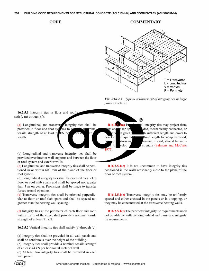
R16.2.5.1(a) Longitudinal integrity ties may project from slabs and be lap spliced, welded, mechanically connected, or embedded in grout joints with sufficient length and cover to develop the required force. Bond length for nonprestressed, bonded prestressing reinforcement, if used, should be suffi-cient to develop the yield strength (Salmons and McCrate 1977).
R16.2.5.1(c) It is not uncommon to have integrity ties positioned in the walls reasonably close to the plane of the floor or roof system.
R16.2.5.1(e) Transverse integrity ties may be uniformly spaced and either encased in the panels or in a topping, or they may be concentrated at the transverse bearing walls.
R16.2.5.1(f) The perimeter integrity tie requirements need not be additive with the longitudinal and transverse integrity tie requirements.
16.2.5.1 Integrity ties in floor and roof systems shall satisfy (a) through (f):
(a) Longitudinal and transverse integrity ties shall be provided in floor and roof systems to provide a nominal tensile strength of at least 22 kN per meter of width or length.
(b) Longitudinal and transverse integrity ties shall be provided over interior wall supports and between the floor or roof system and exterior walls.(c) Longitudinal and transverse integrity ties shall be posi-tioned in or within 600 mm of the plane of the floor or roof system.(d) Longitudinal integrity ties shall be oriented parallel to floor or roof slab spans and shall be spaced not greater than 3 m on center. Provisions shall be made to transfer forces around openings.(e) Transverse integrity ties shall be oriented perpendic-ular to floor or roof slab spans and shall be spaced not greater than the bearing wall spacing.
(f) Integrity ties at the perimeter of each floor and roof, within 1.2 m of the edge, shall provide a nominal tensile strength of at least 71 kN.
16.2.5.2 Vertical integrity ties shall satisfy (a) through (c):
(a) Integrity ties shall be provided in all wall panels and shall be continuous over the height of the building.(b) Integrity ties shall provide a nominal tensile strength of at least 44 kN per horizontal meter of wall.(c) At least two integrity ties shall be provided in each wall panel.
Fig. R16.2.5—Typical arrangement of integrity ties in large panel structures.
American Concrete Institute – Copyrighted © Material – www.concrete.org
208 BUILDING CODE REQUIREMENTS FOR STRUCTURAL CONCRETE (ACI 318M-14) AND COMMENTARY (ACI 318RM-14)
CODE COMMENTARY
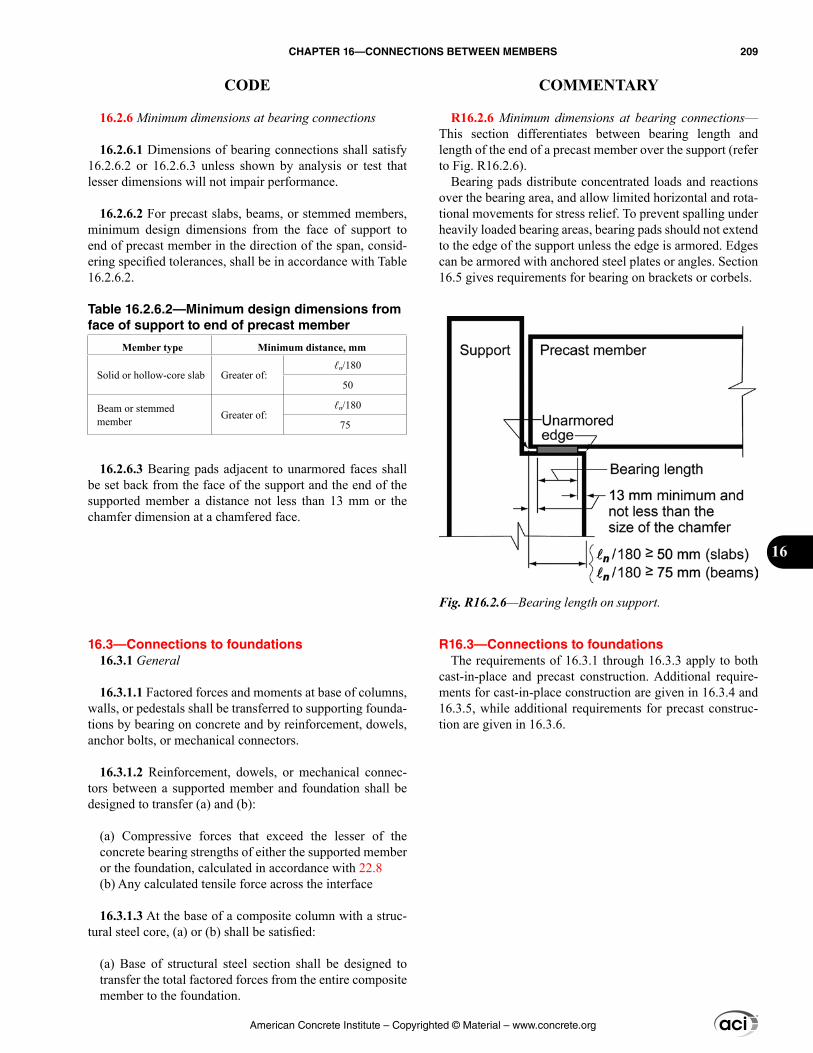
R16.2.6 Minimum dimensions at bearing connections—This section differentiates between bearing length and length of the end of a precast member over the support (refer to Fig. R16.2.6).
Bearing pads distribute concentrated loads and reactions over the bearing area, and allow limited horizontal and rota-tional movements for stress relief. To prevent spalling under heavily loaded bearing areas, bearing pads should not extend to the edge of the support unless the edge is armored. Edges can be armored with anchored steel plates or angles. Section 16.5 gives requirements for bearing on brackets or corbels.
R16.3—Connections to foundations The requirements of 16.3.1 through 16.3.3 apply to both
cast-in-place and precast construction. Additional require-ments for cast-in-place construction are given in 16.3.4 and 16.3.5, while additional requirements for precast construc-tion are given in 16.3.6.
16.2.6 Minimum dimensions at bearing connections
16.2.6.1 Dimensions of bearing connections shall satisfy 16.2.6.2 or 16.2.6.3 unless shown by analysis or test that lesser dimensions will not impair performance.
16.2.6.2 For precast slabs, beams, or stemmed members, minimum design dimensions from the face of support to end of precast member in the direction of the span, consid-ering specified tolerances, shall be in accordance with Table 16.2.6.2.
Table 16.2.6.2—Minimum design dimensions from face of support to end of precast member
Member type Minimum distance, mm
Solid or hollow-core slab Greater of:ℓn/180
50
Beam or stemmed member Greater of:
ℓn/180
75
16.2.6.3 Bearing pads adjacent to unarmored faces shall be set back from the face of the support and the end of the supported member a distance not less than 13 mm or the chamfer dimension at a chamfered face.
16.3—Connections to foundations 16.3.1 General
16.3.1.1 Factored forces and moments at base of columns, walls, or pedestals shall be transferred to supporting founda-tions by bearing on concrete and by reinforcement, dowels, anchor bolts, or mechanical connectors.
16.3.1.2 Reinforcement, dowels, or mechanical connec-tors between a supported member and foundation shall be designed to transfer (a) and (b):
(a) Compressive forces that exceed the lesser of the concrete bearing strengths of either the supported member or the foundation, calculated in accordance with 22.8(b) Any calculated tensile force across the interface
16.3.1.3 At the base of a composite column with a struc-tural steel core, (a) or (b) shall be satisfied:
(a) Base of structural steel section shall be designed to transfer the total factored forces from the entire composite member to the foundation.
Fig. R16.2.6—Bearing length on support.
American Concrete Institute – Copyrighted © Material – www.concrete.org
CHAPTER 16—CONNECTIONS BETWEEN MEMBERS 209
CODE COMMENTARY
16
(b) Base of structural steel section shall be designed to transfer the factored forces from the steel core only, and the remainder of the total factored forces shall be trans-ferred to the foundation by compression in the concrete and by reinforcement.
16.3.2 Required strength
16.3.2.1 Factored forces and moments transferred to foun-dations shall be calculated in accordance with the factored load combinations in Chapter 5 and analysis procedures in Chapter 6.
16.3.3 Design strength
16.3.3.1 Design strengths of connections between columns, walls, or pedestals and foundations shall satisfy Eq. (16.3.3.1) for each applicable load combination. For connections between precast members and foundations, requirements for vertical integrity ties in 16.2.4.3 or 16.2.5.2 shall be satisfied.
ϕSn ≥ U (16.3.3.1)
where Sn is the nominal flexural, shear, axial, torsional, or bearing strength of the connection.
16.3.3.2 ϕ shall be determined in accordance with 21.2.
16.3.3.3 Combined moment and axial strength of connec-tions shall be calculated in accordance with 22.4.
16.3.3.4 At the contact surface between a supported member and foundation, or between a supported member or foundation and an intermediate bearing element, nominal bearing strength Bn shall be calculated in accordance with 22.8 for concrete surfaces. Bn shall be the lesser of the nominal concrete bearing strengths for the supported member or foundation surface, and shall not exceed the strength of intermediate bearing elements, if present.
16.3.3.5 At the contact surface between supported member and foundation, Vn shall be calculated in accordance with the shear-friction provisions in 22.9 or by other appropriate means.
16.3.3.6 At the base of a precast column, pedestal, or wall, anchor bolts and anchors for mechanical connections shall be designed in accordance with Chapter 17. Forces devel-oped during erection shall be considered.
R16.3.3 Design strength
R16.3.3.4 In the common case of a column bearing on a footing, where the area of the footing is larger than the area of the column, the bearing strength should be checked at the base of the column and the top of the footing. In the absence of dowels or column reinforcement that continue into the foundation, the strength of the lower part of the column should be checked using the strength of the concrete alone.
R16.3.3.5 Shear-friction may be used to check for transfer of lateral forces to the supporting pedestal or footing. As an alternative to using shear-friction across a shear plane, shear keys may be used, provided that the reinforcement crossing the joint satisfies 16.3.4.1 for cast-in-place construction or 16.3.6.1 for precast construction. In precast construction, resistance to lateral forces may be provided by mechanical or welded connections.
R16.3.3.6 Chapter 17 covers anchor design, including seismic design requirements. In precast concrete construc-tion, erection considerations may control base connection design and need to be considered.
American Concrete Institute – Copyrighted © Material – www.concrete.org
210 BUILDING CODE REQUIREMENTS FOR STRUCTURAL CONCRETE (ACI 318M-14) AND COMMENTARY (ACI 318RM-14)
CODE COMMENTARY
16.3.3.7 At the base of a precast column, pedestal, or wall, mechanical connectors shall be designed to reach their design strength before anchorage failure or failure of surrounding concrete.
16.3.4 Minimum reinforcement for connections between cast-in-place members and foundation
16.3.4.1 For connections between a cast-in-place column or pedestal and foundation, As crossing the interface shall be at least 0.005Ag, where Ag is the gross area of the supported member.
16.3.4.2 For connections between a cast-in-place wall and foundation, area of vertical reinforcement crossing the inter-face shall satisfy 11.6.1.
16.3.5 Details for connections between cast-in-place members and foundation
16.3.5.1 At the base of a cast-in-place column, pedestal, or wall, reinforcement required to satisfy 16.3.3 and 16.3.4 shall be provided either by extending longitudinal bars into supporting foundation or by dowels.
16.3.5.2 Where moments are transferred to the founda-tion, reinforcement, dowels, or mechanical connectors shall satisfy 10.7.5 for splices.
16.3.5.3 If a pinned or rocker connection is used at the base of a cast-in-place column or pedestal, the connection to foundation shall satisfy 16.3.3.
16.3.5.4 At footings, it shall be permitted to lap splice No. 43 and No. 57 longitudinal bars, in compression only, with dowels to satisfy 16.3.3.1. Dowels shall satisfy (a) through (c):
(a) Dowels shall not be larger than No. 36(b) Dowels shall extend into supported member at least the greater of the development length of the longitudinal bars in compression, ℓdc, and the compression lap splice length of the dowels, ℓsc(c) Dowels shall extend into the footing at least ℓdc of the dowels
16.3.6 Details for connections between precast members and foundation
R16.3.4 Minimum reinforcement for connections between cast-in-place members and foundation—The Code requires a minimum amount of reinforcement between all supported and supporting members to ensure ductile behavior. This reinforcement is required to provide a degree of structural integrity during the construction stage and during the life of the structure.
R16.3.4.1 The minimum area of reinforcement at the base of a column may be provided by extending the longitudinal bars and anchoring them into the footing or by providing properly anchored dowels.
R16.3.5 Details for connections between cast-in-place members and foundation
R16.3.5.2 If calculated moments are transferred from the column to the footing, the concrete in the compression zone of the column may be stressed to 0.85ϕfc′ under factored load conditions and, as a result, all the reinforcement will generally have to be anchored into the footing.
R16.3.5.4 Compression lap splices of large bars and dowels are permitted in accordance with 25.5.5.3. Satisfying 16.3.3.1 might require that each No. 43 or 57 bar be spliced to more than one dowel bar.
American Concrete Institute – Copyrighted © Material – www.concrete.org
CHAPTER 16—CONNECTIONS BETWEEN MEMBERS 211
CODE COMMENTARY
16
16.3.6.1 At the base of a precast column, pedestal, or wall, the connection to the foundation shall satisfy 16.2.4.3 or 16.2.5.2.
16.3.6.2 If the applicable load combinations of 16.3.3 result in no tension at the base of precast walls, vertical integrity ties required by 16.2.4.3(b) shall be permitted to be devel-oped into an adequately reinforced concrete slab-on-ground.
16.4—Horizontal shear transfer in composite concrete flexural members
16.4.1 General
16.4.1.1 In a composite concrete flexural member, full transfer of horizontal shear forces shall be provided at contact surfaces of interconnected elements.
16.4.1.2 Where tension exists across any contact surface between interconnected concrete elements, horizontal shear transfer by contact shall be permitted only where transverse reinforcement is provided in accordance with 16.4.6 and 16.4.7.
16.4.1.3 Surface preparation assumed for design shall be specified in the construction documents.
16.4.2 Required strength
16.4.2.1 Factored forces transferred along the contact surface in composite concrete flexural members shall be calculated in accordance with the factored load combina-tions in Chapter 5.
16.4.2.2 Required strength shall be calculated in accor-dance with the analysis procedures in Chapter 6.
16.4.3 Design strength
16.4.3.1 Design strength for horizontal shear transfer shall satisfy Eq. (16.4.3.1) at all locations along the contact surface in a composite concrete flexural member, unless 16.4.5 is satisfied:
ϕVnh ≥ Vu (16.4.3.1)
where nominal horizontal shear strength Vnh is calculated in accordance with 16.4.4.
16.4.3.2 ϕ shall be determined in accordance with 21.2.
16.4.4 Nominal horizontal shear strength
R16.4—Horizontal shear transfer in composite concrete flexural members
R16.4.1 General
R16.4.1.1 Full transfer of horizontal shear forces between segments of composite members can be provided by hori-zontal shear strength at contact surfaces through interface shear, properly anchored ties, or both.
R16.4.1.3 Section 26.5.6 requires the licensed design professional to specify the surface preparation in the construction documents.
R16.4.4 Nominal horizontal shear strength
American Concrete Institute – Copyrighted © Material – www.concrete.org
212 BUILDING CODE REQUIREMENTS FOR STRUCTURAL CONCRETE (ACI 318M-14) AND COMMENTARY (ACI 318RM-14)
CODE COMMENTARY
16.4.4.1 If Vu > ϕ(3.5bvd), Vnh shall be taken as Vn calcu-lated in accordance with 22.9, where bv is the width of the contact surface, and d is in accordance with 16.4.4.3.
16.4.4.2 If Vu ≤ ϕ(3.5bvd), Vnh shall be calculated in accor-dance with Table 16.4.4.2, where Av,min is in accordance with 16.4.6, bv is the width of the contact surface, and d is in accordance with 16.4.4.3.
16.4.4.3 In Table 16.4.4.2, d shall be the distance from extreme compression fiber for the entire composite section to the centroid of prestressed and nonprestressed longitu-dinal tension reinforcement, if any, but need not be taken less than 0.80h for prestressed concrete members.
16.4.4.4 Transverse reinforcement in the previously cast concrete that extends into the cast-in-place concrete and is anchored on both sides of the interface shall be permitted to be included as ties for calculation of Vnh.
16.4.5 Alternative method for calculating design hori-zontal shear strength
16.4.5.1 As an alternative to 16.4.3.1, factored horizontal shear Vuh shall be calculated from the change in flexural compressive or tensile force in any segment of the composite concrete member, and Eq. (16.4.5.1) shall be satisfied at all locations along the contact surface:
ϕVnh ≥ Vuh (16.4.5.1)
Nominal horizontal shear strength Vnh shall be calcu-lated in accordance with 16.4.4.1 or 16.4.4.2, where area of contact surface shall be substituted for bvd and Vuh shall be substituted for Vu. Provisions shall be made to transfer the change in compressive or tensile force as horizontal shear force across the interface.
16.4.5.2 Where shear transfer reinforcement is designed to resist horizontal shear to satisfy Eq. (16.4.5.1), the tie area to tie spacing ratio along the member shall approxi-mately reflect the distribution of interface shear forces in the composite concrete flexural member.
R16.4.4.2 The permitted horizontal shear strengths and the requirement of 6 mm amplitude for intentional roughness are based on tests discussed in Kaar et al. (1960), Saemann and Washa (1964), and Hanson (1960).
R16.4.4.3 In composite prestressed concrete members, the depth of the tension reinforcement may vary along the member. The definition of d used in Chapter 22 for deter-mining the vertical shear strength is also appropriate for determining the horizontal shear strength.
R16.4.5 Alternative method for calculating design hori-zontal shear strength
R16.4.5.2 The distribution of horizontal shear stresses along the contact surface in a composite member will reflect the distribution of shear along the member. Horizontal shear failure will initiate where the horizontal shear stress is a maximum and will spread to regions of lower stress.
Table 16.4.4.2—Nominal horizontal shear strength
Shear transfer reinforcement Contact surface preparation[1] Vnh, N
Av ≥ Av,min
Concrete placed against hardened concrete intentionally roughened to a full amplitude of approximately 6 mm Lesser of:
1.8 0.6
λ + v yt
vv
A fb d
b s(a)
3.5bvd (b)
Concrete placed against hardened concrete not inten-tionally roughened 0.55bvd (c)
Other cases Concrete placed against hardened concrete intentionally roughened 0.55bvd (d)
[1]Concrete contact surface shall be clean and free of laitance.
American Concrete Institute – Copyrighted © Material – www.concrete.org
CHAPTER 16—CONNECTIONS BETWEEN MEMBERS 213
CODE COMMENTARY
16
16.4.5.3 Transverse reinforcement in a previously cast section that extends into the cast-in-place section and is anchored on both sides of the interface shall be permitted to be included as ties for calculation of Vnh.
16.4.6 Minimum reinforcement for horizontal shear transfer
16.4.6.1 Where shear transfer reinforcement is designed to resist horizontal shear, Av,min shall be the greater of (a) and (b):
(a) 0.062 ′ wc
y
b sf
f
(b) 0.35 w
y
b sf
16.4.7 Reinforcement detailing for horizontal shear transfer
16.4.7.1 Shear transfer reinforcement shall consist of single bars or wire, multiple leg stirrups, or vertical legs of welded wire reinforcement.
16.4.7.2 Where shear transfer reinforcement is designed to resist horizontal shear, longitudinal spacing of shear transfer reinforcement shall not exceed the lesser of 600 mm and four times the least dimension of the supported element.
16.4.7.3 Shear transfer reinforcement shall be developed in interconnected elements in accordance with 25.7.1.
16.5—Brackets and corbels 16.5.1 General
Because the slip at peak horizontal shear resistance is small for a concrete-to-concrete contact surface, longitudinal redistribution of horizontal shear resistance is very limited. Therefore, the spacing of ties along the contact surface should provide horizontal shear resistance distributed approximately the same as the distribution of shear stress along the contact surface.
R16.4.6 Minimum reinforcement for horizontal shear transfer
R16.4.6.1 The requirements for minimum area of shear transfer reinforcement are based on test data given in Kaar et al. (1960), Saemann and Washa (1964), Hanson (1960), Grossfield and Birnstiel (1962), and Mast (1968).
R16.4.7 Reinforcement detailing for horizontal shear transfer
R16.4.7.3 Proper anchorage of ties extending across the interface is required to maintain contact along the interface.
R16.5—Brackets and corbels R16.5.1 General—Brackets and corbels are short cantile-
vers that tend to act as simple trusses or deep beams, rather than beams, which are designed for shear according to 22.5. The corbel shown in Fig. R16.5.1a and Fig. 16.5.1b may fail by shearing along the interface between the column and the corbel, yielding of the tension tie, crushing or splitting of the compression strut, or localized bearing or shearing failure under the loading plate. These failure modes are illustrated and discussed in Elzanaty et al. (1986).
The method of design addressed in this section has only been validated experimentally for av/d ≤ 1.0. In addition, an upper limit is provided for Nuc because this method of design has only been validated experimentally for Nuc ≤ Vu.
American Concrete Institute – Copyrighted © Material – www.concrete.org
214 BUILDING CODE REQUIREMENTS FOR STRUCTURAL CONCRETE (ACI 318M-14) AND COMMENTARY (ACI 318RM-14)
CODE COMMENTARY
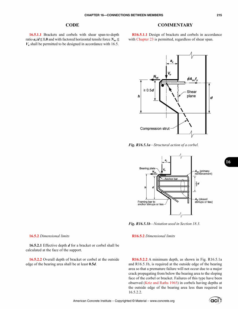
R16.5.1.1 Design of brackets and corbels in accordance with Chapter 23 is permitted, regardless of shear span.
R16.5.2 Dimensional limits
R16.5.2.2 A minimum depth, as shown in Fig. R16.5.1a and R16.5.1b, is required at the outside edge of the bearing area so that a premature failure will not occur due to a major crack propagating from below the bearing area to the sloping face of the corbel or bracket. Failures of this type have been observed (Kriz and Raths 1965) in corbels having depths at the outside edge of the bearing area less than required in 16.5.2.2.
16.5.1.1 Brackets and corbels with shear span-to-depth ratio av/d ≤ 1.0 and with factored horizontal tensile force Nuc ≤ Vu shall be permitted to be designed in accordance with 16.5.
16.5.2 Dimensional limits
16.5.2.1 Effective depth d for a bracket or corbel shall be calculated at the face of the support.
16.5.2.2 Overall depth of bracket or corbel at the outside edge of the bearing area shall be at least 0.5d.
Fig. R16.5.1a—Structural action of a corbel.
Fig. R16.5.1b—Notation used in Section 18.3.
American Concrete Institute – Copyrighted © Material – www.concrete.org
CHAPTER 16—CONNECTIONS BETWEEN MEMBERS 215
CODE COMMENTARY
16
R16.5.2.3 The restriction on the location of the bearing area is necessary to ensure development of the specified yield strength of the primary tension reinforcement near the load.
If the corbel is designed to resist tensile force Nuc, a bearing plate should be provided and fully anchored to the primary tension reinforcement (Fig. R16.5.1b).
R16.5.2.4 These limits impose dimensional restrictions on brackets and corbels necessary to comply with the maximum shear friction strength allowed on the critical section at the face of support.
R16.5.2.5 Tests (Mattock et al. 1976a) have shown that the maximum shear friction strength of lightweight concrete brackets and corbels is a function of both fc′ and av/d. No data are available for corbels or brackets made of sand-light-weight concrete. As a result, the same limitations have been placed on both all-lightweight and sand-lightweight brackets and corbels.
R16.5.3 Required strength
R16.5.3.4 Because the magnitude of horizontal forces acting on corbels or brackets cannot usually be determined with accuracy, it is required that Nuc be amplified by the load factor applicable to live loads.
16.5.2.3 No part of the bearing area on a bracket or corbel shall project farther from the face of support than (a) or (b):
(a) End of the straight portion of the primary tension reinforcement(b) Interior face of the transverse anchor bar, if one is provided
16.5.2.4 For normalweight concrete, the bracket or corbel dimensions shall be selected such that Vu/ϕ shall not exceed the least of (a) through (c):
(a) 0.2fc′bwd(b) (3.3 + 0.08fc′)bwd(c) 11bwd
16.5.2.5 For all-lightweight or sand-lightweight concrete, the bracket or corbel dimensions shall be selected such that Vu/ϕ shall not exceed the lesser of (a) and (b):
(a) 0.2 0.07 vc w
af b d
d − ′
(b) 5.5 1.9 − v
wa
b dd
16.5.3 Required strength
16.5.3.1 The section at the face of the support shall be designed to resist simultaneously the factored shear Vu, the factored horizontal tensile force Nuc, and the factored moment Mu given by [Vuav + Nuc(h – d)].
16.5.3.2 Factored tensile force, Nuc, and shear, Vu, shall be the maximum values calculated in accordance with the factored load combinations in Chapter 5.
16.5.3.3 Required strength shall be calculated in accor-dance with the analysis procedures in Chapter 6, and the requirements in this section.
16.5.3.4 Horizontal tensile force acting on a bracket or corbel shall be treated as a live load when calculating Nuc, even if the tension results from restraint of creep, shrinkage, or temperature change.
16.5.3.5 Unless tensile forces are prevented from being applied to the bracket or corbel, Nuc shall be at least 0.2Vu.
16.5.4 Design strength
16.5.4.1 Design strength at all sections shall satisfy ϕSn ≥ U, including (a) through (c). Interaction between load effects shall be considered.
American Concrete Institute – Copyrighted © Material – www.concrete.org
216 BUILDING CODE REQUIREMENTS FOR STRUCTURAL CONCRETE (ACI 318M-14) AND COMMENTARY (ACI 318RM-14)
CODE COMMENTARY
R16.5.5 Reinforcement limits
R16.5.5.1 Test results (Mattock et al. 1976a) indicate that the total amount of primary tension reinforcement, Asc, required to cross the face of the support should be the greatest of:
(a) The sum of the amount of reinforcement needed to resist demands from flexure, Af, plus the amount of rein-forcement needed to resist the axial force, An, as deter-mined by 16.5.4.3.(b) The sum of two-thirds of the total required shear fric-tion reinforcement, Avf, as determined by 16.5.4.4, plus the amount of reinforcement needed to resist the axial force, An, determined by 16.5.4.3. The remaining Avf/3 should be provided as closed stirrups parallel to Asc as required by 16.5.5.2.(c) A minimum amount of reinforcement, multiplied by the ratio of concrete strength to steel strength. This amount is required to prevent the possibility of sudden failure should the bracket or corbel crack under the action of flexure and outward tensile force.
R16.5.5.2 Closed stirrups parallel to the primary tension reinforcement are necessary to prevent a premature diagonal tension failure of the corbel or bracket. Distribution of Ah is required to be in accordance with 16.5.6.6. The total amount of reinforcement required to cross the face of the support, as shown in Fig. R16.5.1b, is the sum of Asc and Ah.
R16.5.6 Reinforcement detailing
(a) ϕNn ≥ Nuc(b) ϕVn ≥ Vu(c) ϕMn ≥ Mu
16.5.4.2 ϕ shall be determined in accordance with 21.2.
16.5.4.3 Nominal tensile strength Nn provided by An shall be calculated by
Nn = Anfy (16.5.4.3)
16.5.4.4 Nominal shear strength Vn provided by Avf shall be calculated in accordance with provisions for shear-friction in 22.9, where Avf is the area of reinforcement that crosses the assumed shear plane.
16.5.4.5 Nominal flexural strength Mn provided by Af shall be calculated in accordance with the design assump-tions in 22.2.
16.5.5 Reinforcement limits
16.5.5.1 Area of primary tension reinforcement, Asc, shall be at least the greatest of (a) through (c):
(a) Af + An(b) (2/3)Avf + An(c) 0.04(fc′/fy)(bwd)
16.5.5.2 Total area of closed stirrups or ties parallel to primary tension reinforcement, Ah, shall be at least:
Ah = 0.5(Asc – An) (16.5.5.2)
16.5.6 Reinforcement detailing
16.5.6.1 Concrete cover shall be in accordance with 20.6.1.3.
American Concrete Institute – Copyrighted © Material – www.concrete.org
CHAPTER 16—CONNECTIONS BETWEEN MEMBERS 217
CODE COMMENTARY
16
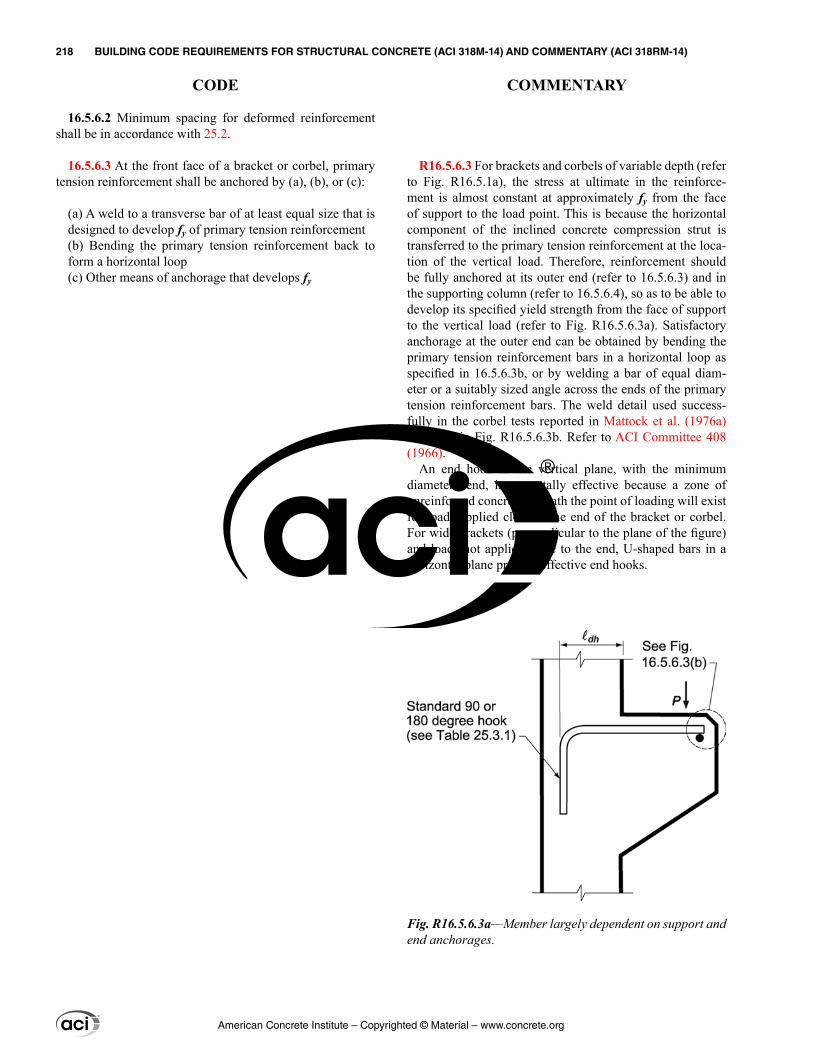
R16.5.6.3 For brackets and corbels of variable depth (refer to Fig. R16.5.1a), the stress at ultimate in the reinforce-ment is almost constant at approximately fy from the face of support to the load point. This is because the horizontal component of the inclined concrete compression strut is transferred to the primary tension reinforcement at the loca-tion of the vertical load. Therefore, reinforcement should be fully anchored at its outer end (refer to 16.5.6.3) and in the supporting column (refer to 16.5.6.4), so as to be able to develop its specified yield strength from the face of support to the vertical load (refer to Fig. R16.5.6.3a). Satisfactory anchorage at the outer end can be obtained by bending the primary tension reinforcement bars in a horizontal loop as specified in 16.5.6.3b, or by welding a bar of equal diam-eter or a suitably sized angle across the ends of the primary tension reinforcement bars. The weld detail used success-fully in the corbel tests reported in Mattock et al. (1976a) is shown in Fig. R16.5.6.3b. Refer to ACI Committee 408 (1966).
An end hook in the vertical plane, with the minimum diameter bend, is not totally effective because a zone of unreinforced concrete beneath the point of loading will exist for loads applied close to the end of the bracket or corbel. For wide brackets (perpendicular to the plane of the figure) and loads not applied close to the end, U-shaped bars in a horizontal plane provide effective end hooks.
16.5.6.2 Minimum spacing for deformed reinforcement shall be in accordance with 25.2.
16.5.6.3 At the front face of a bracket or corbel, primary tension reinforcement shall be anchored by (a), (b), or (c):
(a) A weld to a transverse bar of at least equal size that is designed to develop fy of primary tension reinforcement(b) Bending the primary tension reinforcement back to form a horizontal loop(c) Other means of anchorage that develops fy
Fig. R16.5.6.3a—Member largely dependent on support and end anchorages.
American Concrete Institute – Copyrighted © Material – www.concrete.org
218 BUILDING CODE REQUIREMENTS FOR STRUCTURAL CONCRETE (ACI 318M-14) AND COMMENTARY (ACI 318RM-14)
CODE COMMENTARY
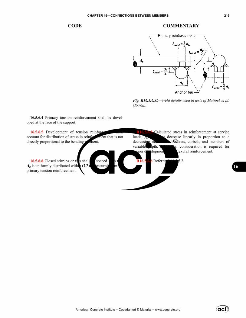
R16.5.6.5 Calculated stress in reinforcement at service loads, fs, does not decrease linearly in proportion to a decreasing moment in brackets, corbels, and members of variable depth. Additional consideration is required for proper development of the flexural reinforcement.
R16.5.6.6 Refer to R16.5.5.2.
16.5.6.4 Primary tension reinforcement shall be devel-oped at the face of the support.
16.5.6.5 Development of tension reinforcement shall account for distribution of stress in reinforcement that is not directly proportional to the bending moment.
16.5.6.6 Closed stirrups or ties shall be spaced such that Ah is uniformly distributed within (2/3)d measured from the primary tension reinforcement.
Fig. R16.5.6.3b—Weld details used in tests of Mattock et al. (1976a).
American Concrete Institute – Copyrighted © Material – www.concrete.org
CHAPTER 16—CONNECTIONS BETWEEN MEMBERS 219
CODE COMMENTARY
16

American Concrete Institute – Copyrighted © Material – www.concrete.org
220 BUILDING CODE REQUIREMENTS FOR STRUCTURAL CONCRETE (ACI 318M-14) AND COMMENTARY (ACI 318RM-14)
Notes
CHAPTER 17—ANCHORING TO CONCRETE
17.1—Scope 17.1.1 This chapter provides design requirements for
anchors in concrete used to transmit structural loads by means of tension, shear, or a combination of tension and shear between: (a) connected structural elements; or (b) safety-related attachments and structural elements. Safety levels specified are intended for in-service conditions, rather than for short-term handling and construction conditions.
17.1.2 This chapter applies to cast-in anchors and to post-installed expansion (torque-controlled and displacement-controlled), undercut, and adhesive anchors. Adhesive anchors shall be installed in concrete having a minimum age of 21 days at time of anchor installation. Specialty inserts, through-bolts, multiple anchors connected to a single steel plate at the embedded end of the anchors, grouted anchors, and direct anchors such as powder or pneumatic actuated nails or bolts are not included in the provisions of this chapter. Reinforcement used as part of the embedment shall be designed in accordance with other parts of this Code.
17.1.3 Design provisions are included for the following types of anchors:
(a) Headed studs and headed bolts having a geometry that has been demonstrated to result in a pullout strength in uncracked concrete equal to or exceeding 1.4Np, where Np is given in Eq. (17.4.3.4)(b) Hooked bolts having a geometry that has been demon-strated to result in a pullout strength without the benefit of friction in uncracked concrete equal to or exceeding 1.4Np, where Np is given in Eq. (17.4.3.5)(c) Post-installed expansion and undercut anchors that meet the assessment criteria of ACI 355.2(d) Adhesive anchors that meet the assessment criteria of ACI 355.4
R17—ANCHORING TO CONCRETE
R17.1—Scope R17.1.1 This chapter is restricted in scope to structural
anchors that transmit structural loads related to strength, stability, or life safety. Two types of applications are envi-sioned. The first is connections between structural elements where the failure of an anchor or an anchor group could result in loss of equilibrium or stability of any portion of the struc-ture. The second is where safety-related attachments that are not part of the structure (such as sprinkler systems, heavy suspended pipes, or barrier rails) are attached to structural elements. The levels of safety defined by the combinations of load factors and ϕ-factors are appropriate for structural applications. Other standards may require more stringent safety levels during temporary handling.
R17.1.2 Provisions for design of adhesive anchors were added in the 2011 Code. Adhesive anchors are particularly sensitive to a number of factors including installation direc-tion and loading type. Where adhesive anchors are used to resist sustained tension, the provisions include testing requirements for horizontal and upwardly inclined installa-tions in 17.2.4 and design and certification requirements for sustained tension load cases in 17.2.5 and 17.8.2.2 through 17.8.2.4, respectively. Adhesive anchors qualified in accor-dance with ACI 355.4 are tested in concrete with compres-sive strengths within two ranges: 17 to 28 MPa and 45 to 59 MPa. Bond strength is, in general, not highly sensitive to concrete compressive strength. The design performance of adhesive anchors cannot be ensured by establishing a minimum concrete compressive strength at the time of installation in early-age concrete. Therefore, a minimum concrete age of 21 days at the time of adhesive anchor instal-lation was adopted.
The wide variety of shapes and configurations of specialty inserts precludes prescription of generalized tests and design equations. Specialty inserts are not covered by Chapter 17 provisions.
R17.1.3 Typical cast-in headed studs and headed bolts with geometries consistent with ASME B1.1, B18.2.1, and B18.2.6 have been tested and proven to behave predictably, so calculated pullout strengths are acceptable.
Post-installed anchors do not have predictable pullout strengths, and therefore qualification tests to establish the pullout strengths per ACI 355.2 are required. For a post-installed anchor to be used in conjunction with the require-ments of this chapter, the results of the ACI 355.2 tests have to indicate that pullout failures exhibit an acceptable load-displacement characteristic or that pullout failures are precluded by another failure mode. For adhesive anchors, the characteristic bond stress and suitability for structural applications are established by testing in accordance with ACI 355.4.
American Concrete Institute – Copyrighted © Material – www.concrete.org
CHAPTER 17—ANCHORING TO CONCRETE 221
CODE COMMENTARY
17
R17.1.4 The exclusion from the scope of load applica-tions producing high cycle fatigue or extremely short dura-tion impact (such as blast or shock wave) are not meant to exclude seismic load effects. Section 17.2.3 presents additional requirements for design when seismic loads are included.
R17.2—General R17.2.1 When the strength of an anchor group is governed
by breakage of the concrete, the behavior is brittle and there is limited redistribution of the forces between the highly stressed and less stressed anchors. In this case, the theory of elasticity is required to be used, assuming the attachment that distributes loads to the anchors is sufficiently stiff. The forces in the anchors are considered to be proportional to the external load and its distance from the neutral axis of the anchor group.
If anchor strength is governed by ductile yielding of the anchor steel, significant redistribution of anchor forces can occur. In this case, an analysis based on the theory of elas-ticity will be conservative. Cook and Klingner (1992a,b) and Lotze et al. (2001) discuss nonlinear analysis, using theory of plasticity, for the determination of the capacities of ductile anchor groups.
R17.2.3 Seismic design—Unless 17.2.3.4.1 or 17.2.3.5.1 apply, all anchors in structures assigned to Seismic Design Categories (SDC) C, D, E, or F are required to satisfy the additional requirements of 17.2.3.1 through 17.2.3.7, regard-less of whether earthquake loads are included in the control-ling load combination for the anchor design. In addition, all post-installed anchors in structures assigned to SDC C, D, E, or F must meet the requirements of ACI 355.2 or ACI 355.4 for prequalification of anchors to resist earthquake loads. Ideally, for tension loadings, anchor strength should be governed by yielding of the ductile steel element of the anchor. If the anchor cannot meet the specified ductility requirements of 17.2.3.4.3(a), then the attachment should be either designed to yield if it is structural or light gauge steel, or designed to crush if it is wood. If ductility requirements of 17.2.3.4.3(a) are satisfied, then any attachments to the anchor should be designed not to yield. In designing attach-ments using yield mechanisms to provide adequate ductility, as permitted by 17.2.3.4.3(b) and 17.2.3.5.3(a), the ratio of specified yield strength to expected strength for the material of the attachment should be considered in determining the design force. The value used for the expected strength should consider both material overstrength and strain hardening effects. For example, the material in a connection element could yield and, due to an increase in its strength with strain hardening, cause a secondary failure of a sub-element or
17.1.4 Load applications that are predominantly high cycle fatigue or impact loads are not covered by this chapter.
17.2—General 17.2.1 Anchors and anchor groups shall be designed for
critical effects of factored loads as determined by elastic anal-ysis. Plastic analysis approaches are permitted where nominal strength is controlled by ductile steel elements, provided that deformational compatibility is taken into account.
17.2.1.1 Anchor group effects shall be considered wher-ever two or more anchors have spacing less than the critical spacing as follows:
Failure mode under investigation Critical spacing
Concrete breakout in tension 3hef
Bond strength in tension 2cNa
Concrete breakout in shear 3ca1
Only those anchors susceptible to the particular failure mode under investigation shall be included in the group.
17.2.2 The design strength of anchors shall equal or exceed the largest required strength calculated from the applicable load combinations in 5.3.
17.2.3 Seismic design
17.2.3.1 Anchors in structures assigned to Seismic Design Category (SDC) C, D, E, or F shall satisfy the additional requirements of 17.2.3.2 through 17.2.3.7.
American Concrete Institute – Copyrighted © Material – www.concrete.org
222 BUILDING CODE REQUIREMENTS FOR STRUCTURAL CONCRETE (ACI 318M-14) AND COMMENTARY (ACI 318RM-14)
CODE COMMENTARY
place extra force or deformation demands on the anchors. For a structural steel attachment, if only the specified yield strength of the steel is known, the expected strength should be taken as approximately 1.5 times the specified yield strength. If the actual yield strength of the steel is known, the expected strength should be taken as approximately 1.25 times the actual yield strength.
Under seismic conditions, the direction of shear may not be predictable. The full shear force should be assumed in any direction for a safe design.
R17.2.3.2 The design provisions in this chapter do not apply for anchors in plastic hinge zones. The possible higher levels of cracking and spalling in plastic hinge zones are beyond the conditions for which the nominal concrete-governed strength values in this chapter are applicable. Plastic hinge zones are considered to extend a distance equal to twice the member depth from any column or beam face, and also include any other sections in walls, frames, and slabs where yielding of reinforcement is likely to occur as a result of lateral displacements.
Where anchors must be located in plastic hinge regions, they should be detailed so that the anchor forces are trans-ferred directly to anchor reinforcement that is designed to carry the anchor forces into the body of the member beyond the anchorage region. Configurations that rely on concrete tensile strength should not be used.
R17.2.3.3 Anchors that are not suitable for use in cracked concrete should not be used to resist earthquake loads. Qualification of post-installed anchors for use in cracked concrete is an integral part of the qualification for resisting earthquake loads in ACI 355.2 and ACI 355.4. The design values obtained from the Simulated Seismic Tests of ACI 355.2 and ACI 355.4 are expected to be less than those for static load applications.
R17.2.3.4 Requirements for tensile loading
R17.2.3.4.1 The requirements of 17.2.3.4.3 need not apply where the applied earthquake tensile force is a small fraction of the total factored tension force.
R17.2.3.4.2 If the ductile steel element is ASTM A36M or ASTM A307 steel, the futa/fya value is typically approxi-mately 1.5 and the anchor can stretch considerably before rupturing at the threads. For other steels, calculations may need to be made to ensure that a similar behavior can occur. Section R17.4.1.2 provides additional information on the steel properties of anchors. Provision of upset threaded ends, whereby the threaded end of the rod is enlarged to compen-sate for the area reduction associated with threading, can
17.2.3.2 The provisions of this chapter do not apply to the design of anchors in plastic hinge zones of concrete struc-tures under earthquake forces.
17.2.3.3 Post-installed anchors shall be qualified for earth-quake loading in accordance with ACI 355.2 or ACI 355.4. The pullout strength Np and steel strength in shear Vsa of expansion and undercut anchors shall be based on the results of the ACI 355.2 Simulated Seismic Tests. For adhesive anchors, the steel strength in shear, Vsa, and the character-istic bond stresses, τuncr and τcr, shall be based on results of the ACI 355.4 Simulated Seismic Tests.
17.2.3.4 Requirements for tensile loading
17.2.3.4.1 Where the tensile component of the strength-level earthquake force applied to a single anchor or group of anchors is equal to or less than 20 percent of the total factored anchor tensile force associated with the same load combination, it shall be permitted to design a single anchor or group of anchors to satisfy 17.4 and the tensile strength requirements of 17.3.1.1.
17.2.3.4.2 Where the tensile component of the strength-level earthquake force applied to anchors exceeds 20 percent of the total factored anchor tensile force associated with the same load combination, anchors and their attachments shall be designed in accordance with 17.2.3.4.3. The anchor design tensile strength shall be determined in accordance with 17.2.3.4.4.
American Concrete Institute – Copyrighted © Material – www.concrete.org
CHAPTER 17—ANCHORING TO CONCRETE 223
CODE COMMENTARY
17
ensure that yielding occurs over the stretch length regardless of the ratio of the yield to ultimate strength of the anchor.
R17.2.3.4.3 Four options are provided for determining the required anchor or attachment strength to protect against nonductile tension failure:
In option (a), anchor ductility requirements are imposed and the required anchor strength is that determined using strength-level earthquake forces acting on the structure. Research (Hoehler and Eligehausen 2008; Vintzileou and Eligehausen 1992) has shown that if the steel of the anchor yields before the concrete anchorage fails, no reduction in the anchor tensile strength is needed for earthquake loadings. Ductile steel anchors should satisfy the definition for ductile steel elements in Chapter 2. To facilitate comparison between steel strength, which is based on the most highly-stressed anchor, and concrete strength based on group behavior, the design is performed on the basis of the ratio of applied load to strength for the steel and concrete, respectively.
For some structures, anchors provide the best locations for energy dissipation in the nonlinear range of response. The stretch length of the anchor affects the lateral displacement capacity of the structure and, therefore, that length needs to be sufficient such that the displacement associated with the design-basis earthquake can be achieved (FEMA P750). Observations from earthquakes indicate that the provision of a stretch length of eight anchor diameters results in good structural performance. Where the required stretch length is calculated, the relative stiffness of the connected elements needs to be considered. When an anchor is subject to load reversals, and its yielding length outside the concrete exceeds six anchor diameters, buckling of the anchor in compression is likely. Buckling can be restrained by placing the anchor in a tube. However, care must be taken that the tube does not share in resisting the tensile load assumed to act on the anchor. For anchor bolts that are not threaded over their length, it is important to ensure that yielding occurs over the unthreaded portion of the bolt within the stretch length prior to failure in the threads. This is accomplished by maintaining sufficient margin between the specified yield and ultimate strengths of the bolt. It should be noted that the available stretch length may be adversely influenced by construction techniques (for example, the addition of leveling nuts to the examples shown in Fig. R17.2.3.4.3).
In option (b), the anchor is designed for the tension force associated with the expected strength of the metal or similar material of the attachment. For option (b), as discussed in R17.2.3, care must be taken in design to consider the conse-quences of potential differences between the specified yield strength and the expected strength of the attachment. An example is 18.5.2.2 for the design of connections of inter-mediate precast walls where a connection not designed to yield should develop at least 1.5Sy, where Sy is the nominal strength of the yielding element based on its specified yield strength. Similarly, steel design manuals require structural steel connections that are designated nonyielding and part of
17.2.3.4.3 Anchors and their attachments shall satisfy one of options (a) through (d):
(a) For single anchors, the concrete-governed strength shall be greater than the steel strength of the anchor. For anchor groups, the ratio of the tensile load on the most highly stressed anchor to the steel strength of that anchor shall be equal to or greater than the ratio of the tensile load on tension loaded anchors to the concrete-governed strength of those anchors. In each case:
(i) The steel strength shall be taken as 1.2 times the nominal steel strength of the anchor.(ii) The concrete-governed strength shall be taken as the nominal strength considering pullout, side-face blowout, concrete breakout, and bond strength as appli-cable. For consideration of pullout in groups, the ratio shall be calculated for the most highly stressed anchor.
In addition, the following shall be satisfied:(iii) Anchors shall transmit tensile loads via a ductile steel element with a stretch length of at least eight anchor diameters unless otherwise determined by analysis.(iv) Where anchors are subject to load reversals, the anchor shall be protected against buckling.(v) Where connections are threaded and the ductile steel elements are not threaded over their entire length, the ratio of futa/fya shall not be less than 1.3 unless the threaded portions are upset. The upset portions shall not be included in the stretch length.(vi) Deformed reinforcing bars used as ductile steel elements to resist earthquake effects shall be limited to ASTM A615M Grades 280 and 420 satisfying the requirements of 20.2.2.5(b) or ASTM A706M Grade 420.
(b) The anchor or group of anchors shall be designed for the maximum tension that can be transmitted to the anchor or group of anchors based on the development of a ductile yield mechanism in the attachment in tension, flexure, shear, or bearing, or a combination of those conditions, and considering both material overstrength and strain hardening effects for the attachment. The anchor design tensile strength shall be calculated from 17.2.3.4.4.(c) The anchor or group of anchors shall be designed for the maximum tension that can be transmitted to the anchors by a non-yielding attachment. The anchor design tensile strength shall be calculated from 17.2.3.4.4.(d) The anchor or group of anchors shall be designed for the maximum tension obtained from design load combina-tions that include E, with E increased by Ωo. The anchor design tensile strength shall satisfy the tensile strength requirements of 17.2.3.4.4.
American Concrete Institute – Copyrighted © Material – www.concrete.org
224 BUILDING CODE REQUIREMENTS FOR STRUCTURAL CONCRETE (ACI 318M-14) AND COMMENTARY (ACI 318RM-14)
CODE COMMENTARY
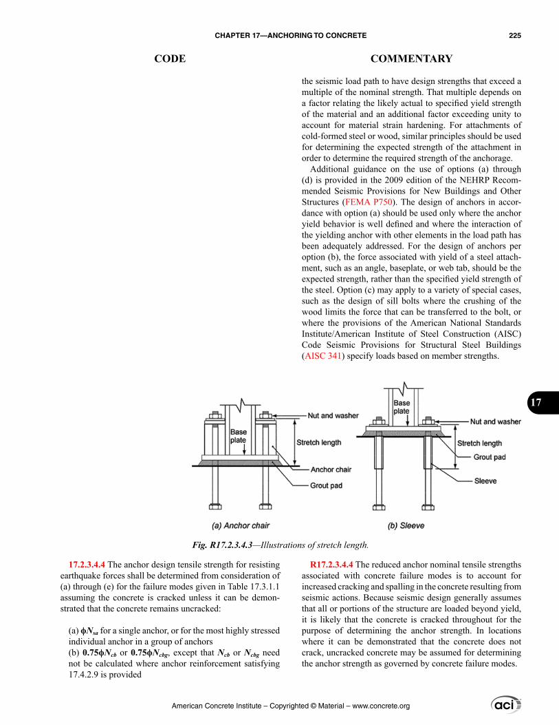
the seismic load path to have design strengths that exceed a multiple of the nominal strength. That multiple depends on a factor relating the likely actual to specified yield strength of the material and an additional factor exceeding unity to account for material strain hardening. For attachments of cold-formed steel or wood, similar principles should be used for determining the expected strength of the attachment in order to determine the required strength of the anchorage.
Additional guidance on the use of options (a) through (d) is provided in the 2009 edition of the NEHRP Recom-mended Seismic Provisions for New Buildings and Other Structures (FEMA P750). The design of anchors in accor-dance with option (a) should be used only where the anchor yield behavior is well defined and where the interaction of the yielding anchor with other elements in the load path has been adequately addressed. For the design of anchors per option (b), the force associated with yield of a steel attach-ment, such as an angle, baseplate, or web tab, should be the expected strength, rather than the specified yield strength of the steel. Option (c) may apply to a variety of special cases, such as the design of sill bolts where the crushing of the wood limits the force that can be transferred to the bolt, or where the provisions of the American National Standards Institute/American Institute of Steel Construction (AISC) Code Seismic Provisions for Structural Steel Buildings (AISC 341) specify loads based on member strengths.
R17.2.3.4.4 The reduced anchor nominal tensile strengths associated with concrete failure modes is to account for increased cracking and spalling in the concrete resulting from seismic actions. Because seismic design generally assumes that all or portions of the structure are loaded beyond yield, it is likely that the concrete is cracked throughout for the purpose of determining the anchor strength. In locations where it can be demonstrated that the concrete does not crack, uncracked concrete may be assumed for determining the anchor strength as governed by concrete failure modes.
17.2.3.4.4 The anchor design tensile strength for resisting earthquake forces shall be determined from consideration of (a) through (e) for the failure modes given in Table 17.3.1.1 assuming the concrete is cracked unless it can be demon-strated that the concrete remains uncracked:
(a) ϕNsa for a single anchor, or for the most highly stressed individual anchor in a group of anchors(b) 0.75ϕNcb or 0.75ϕNcbg, except that Ncb or Ncbg need not be calculated where anchor reinforcement satisfying 17.4.2.9 is provided
Fig. R17.2.3.4.3—Illustrations of stretch length.
American Concrete Institute – Copyrighted © Material – www.concrete.org
CHAPTER 17—ANCHORING TO CONCRETE 225
CODE COMMENTARY
17
(c) 0.75ϕNpn for a single anchor, or for the most highly stressed individual anchor in a group of anchors(d) 0.75ϕNsb or 0.75ϕNsbg(e) 0.75ϕNa or 0.75ϕNag
where ϕ is in accordance with 17.3.3.
17.2.3.4.5 Where anchor reinforcement is provided in accordance with 17.4.2.9, no reduction in design tensile strength beyond that specified in 17.4.2.9 shall be required.
17.2.3.5 Requirements for shear loading
17.2.3.5.1 Where the shear component of the strength-level earthquake force applied to the anchor or group of anchors is equal to or less than 20 percent of the total factored anchor shear force associated with the same load combina-tion, it shall be permitted to design the anchor or group of anchors to satisfy 17.5 and the shear strength requirements of 17.3.1.1.
17.2.3.5.2 Where the shear component of the strength-level earthquake force applied to anchors exceeds 20 percent of the total factored anchor shear force associated with the
R17.2.3.4.5 Where anchor reinforcement as defined in 17.4.2.9 and 17.5.2.9 is used, with the properties as defined in 20.2.2.5, no separation of the potential breakout prism from the substrate is likely to occur provided the anchor reinforcement is designed for a load greater than the concrete breakout strength.
R17.2.3.5 Requirements for shear loading—Where the shear component of the earthquake force applied to the anchor exceeds 20 percent of the total anchor shear force, three options are recognized for determining the required shear strength to protect the anchor or group of anchors against premature shear failure. Option (a) of 17.2.3.4.3 is not available for shear because the cross section of the steel element of the anchor cannot be configured so that steel failure in shear provides any meaningful degree of ductility.
Design of the anchor or group of anchors for the strength associated with force-limiting mechanisms under option (b), such as the bearing strength at holes in a steel attachment or the combined crushing and bearing strength for wood members, may be particularly relevant. Tests on typical anchor bolt connections for wood-framed shear walls (Fennel et al. 2009) showed that wood components attached to concrete with minimum edge distances exhibited ductile behavior. Wood “yield” (crushing) was the first limiting state and resulted in nail slippage in shear. Nail slippage combined with bolt bending provided the required ductility and tough-ness for the shear walls and limited the loads acting on the bolts. Procedures for defining bearing and shear limit states for connections to cold-formed steel are described in AISI S100 and examples of strength calculations are provided in the AISI manual (AISI D100). In such cases, consider-ation should be given to whether exceedance of the bearing strength may lead to tearing and an unacceptable loss of connectivity. Where anchors are located far from edges it may not be possible to design such that anchor reinforcement controls the anchor strength. In such cases, anchors should be designed for overstrength in accordance with option (c).
R17.2.3.5.1 The requirements of 17.2.3.5.3 need not apply where the applied earthquake shear force is a small fraction of the total factored shear force.
American Concrete Institute – Copyrighted © Material – www.concrete.org
226 BUILDING CODE REQUIREMENTS FOR STRUCTURAL CONCRETE (ACI 318M-14) AND COMMENTARY (ACI 318RM-14)
CODE COMMENTARY
same load combination, anchors and their attachments shall be designed in accordance with 17.2.3.5.3. The anchor design shear strength for resisting earthquake forces shall be determined in accordance with 17.5.
17.2.3.5.3 Anchors and their attachments shall be designed using one of options (a) through (c):
(a) The anchor or group of anchors shall be designed for the maximum shear that can be transmitted to the anchor or group of anchors based on the development of a ductile yield mechanism in the attachment in flexure, shear, or bearing, or a combination of those conditions, and consid-ering both material overstrength and strain hardening effects in the attachment.(b) The anchor or group of anchors shall be designed for the maximum shear that can be transmitted to the anchors by a non-yielding attachment.(c) The anchor or group of anchors shall be designed for the maximum shear obtained from design load combina-tions that include E, with E increased by Ωo. The anchor design shear strength shall satisfy the shear strength requirements of 17.3.1.1.
17.2.3.5.4 Where anchor reinforcement is provided in accordance with 17.5.2.9, no reduction in design shear strength beyond that specified in 17.5.2.9 shall be required.
17.2.3.6 Single anchors or groups of anchors that are subjected to both tension and shear forces shall be designed to satisfy the requirements of 17.6, with the anchor design tensile strength calculated from 17.2.3.4.4.
17.2.3.7 Anchor reinforcement used in structures assigned to SDC C, D, E, or F shall be deformed reinforcement and shall be limited to ASTM A615M Grades 280 and 420 satis-fying the requirements of 20.2.2.5(b) (i) and (ii) or ASTM A706M Grade 420.
17.2.4 Adhesive anchors installed horizontally or upwardly inclined shall be qualified in accordance with ACI 355.4 requirements for sensitivity to installation direction.
17.2.5 For adhesive anchors subjected to sustained tension loading, 17.3.1.2 shall be satisfied. For groups of adhesive anchors, Eq. (17.3.1.2) shall be satisfied for the anchor that resists the highest sustained tension load. Installer certi-fication and inspection requirements for horizontal and upwardly inclined adhesive anchors subjected to sustained tension loading shall be in accordance with 17.8.2.2 through 17.8.2.4.
R17.2.4 ACI 355.4 includes optional tests to confirm the suitability of adhesive anchors for horizontal and upwardly inclined installations.
R17.2.5 For adhesive anchors subjected to sustained tension loading, an additional calculation for the sustained portion of the factored load for a reduced bond resistance is required to account for possible bond strength reductions under sustained load. The resistance of adhesive anchors to sustained tension load is particularly dependent on correct installation, including hole cleaning, adhesive metering and mixing, and prevention of voids in the adhesive bond line (annular gap). In addition, care should be taken in the selection of the correct adhesive and bond strength for the expected on-site conditions such as the concrete condi-tion during installation (dry or saturated, cold or hot), the drilling method used (rotary impact drill, rock drill, or core
American Concrete Institute – Copyrighted © Material – www.concrete.org
CHAPTER 17—ANCHORING TO CONCRETE 227
CODE COMMENTARY
17
17.2.6 Modification factor λa for lightweight concrete shall be taken as:
Cast-in and undercut anchor concrete failure ..............1.0λExpansion and adhesive anchor concrete failure ........0.8λAdhesive anchor bond failure per Eq. (17.4.5.2) ........0.6λ
where λ is determined in accordance with 19.2.4. It shall be permitted to use an alternative value of λa where tests have been performed and evaluated in accordance with ACI 355.2 or ACI 355.4.
17.2.7 The values of fc′ used for calculation purposes in this chapter shall not exceed 70 MPa for cast-in anchors, and 55 MPa for post-installed anchors. Testing is required for post-installed anchors when used in concrete with fc′ greater than 55 MPa.
17.3—General requirements for strength of anchors
17.3.1 Strength design of anchors shall be based either on computation using design models that satisfy the require-ments of 17.3.2, or on test evaluation using the 5 percent fractile of applicable test results for the following:
(a) Steel strength of anchor in tension (17.4.1)(b) Concrete breakout strength of anchor in tension (17.4.2)
drill), and anticipated in-service temperature variations in the concrete. Installer certification and inspection require-ments associated with the use of adhesive anchors for hori-zontal and upwardly inclined installations to resist sustained tension loads are addressed in 17.8.2.2 through 17.8.2.4.
Adhesive anchors are particularly sensitive to installation direction and loading type. Adhesive anchors installed over-head that resist sustained tension loads are of concern because previous applications of this type have led to failures. Other anchor types may be more appropriate for such cases. Where adhesive anchors are used in overhead applications subjected to sustained tension loading, it is essential to meet test require-ments of ACI 355.4 for sensitivity to installation direction, use certified installers, and require special inspection.
R17.2.6 The number of tests available to establish the strength of anchors in lightweight concrete is limited. Light-weight concrete tests of cast-in headed studs indicate that the present reduction factor λ adequately captures the influ-ence of lightweight concrete (Shaikh and Yi 1985; Anderson and Meinheit 2005). Anchor manufacturer data developed for evaluation reports on both post-installed expansion and adhesive anchors indicate that a reduced λ is needed to provide the necessary safety factor for the respective design strength. ACI 355.2 and ACI 355.4 provide procedures whereby a specific value of λa can be used based on testing, assuming the lightweight concrete is similar to the reference test material.
R17.2.7 A limited number of tests of cast-in and post-installed anchors in high-strength concrete (Primavera et al. 1997) indicate that the design procedures contained in this chapter become unconservative, particularly for cast-in anchors in concrete with compressive strengths in the range of 75 to 85 MPa. Until further tests are available, an upper limit on fc′ of 70 MPa has been imposed in the design of cast-in anchors. This limitation is consistent with 22.5.3 and 25.4.1.4. ACI 355.2 and ACI 355.4 do not require testing of post-installed anchors in concrete with fc′ greater than 55 MPa. Some post-installed expansion anchors may have difficulty expanding in very high-strength concretes and the bond strength of adhesive anchors may be negatively affected by very high-strength concrete. Therefore, fc′ is limited to 55 MPa in the design of post-installed anchors unless testing is performed.
R17.3—General requirements for strength of anchors
R17.3.1 This section provides requirements for estab-lishing the strength of anchors in concrete. The various types of steel and concrete failure modes for anchors are shown in Fig. R17.3.1(a) and R17.3.1(b). Comprehensive discussions of anchor failure modes are included in Design of Fasten-ings in Concrete (1997), Fuchs et al. (1995), Eligehausen and Balogh (1995), and Cook et al. (1998). Tension failure modes related to concrete capacity include concrete breakout
American Concrete Institute – Copyrighted © Material – www.concrete.org
228 BUILDING CODE REQUIREMENTS FOR STRUCTURAL CONCRETE (ACI 318M-14) AND COMMENTARY (ACI 318RM-14)
CODE COMMENTARY
(c) Pullout strength cast-in, post-installed expansion, or undercut anchor in tension (17.4.3)(d) Concrete side-face blowout strength of headed anchor in tension (17.4.4)(e) Bond strength of adhesive anchor in tension (17.4.5)(f) Steel strength of anchor in shear (17.5.1)(g) Concrete breakout strength of anchor in shear (17.5.2)(h) Concrete pryout strength of anchor in shear (17.5.3)
In addition, anchors shall satisfy the required edge distances, spacings, and thicknesses to preclude splitting failure, as required in 17.7.
17.3.1.1 The design of anchors shall be in accordance with Table 17.3.1.1. In addition, the design of anchors shall satisfy 17.2.3 for earthquake loading and 17.3.1.2 for adhe-sive anchors subject to sustained tensile loading.
Table 17.3.1.1—Required strength of anchors, except as noted in 17.2.3
Failure modeSingle anchor
Anchor group[1]
Individual anchor in a
groupAnchors as
a groupSteel strength in tension (17.4.1) ϕNsa ≥ Nua ϕNsa ≥ Nua,i
Concrete breakout strength in tension (17.4.2) ϕNcb ≥ Nua ϕNcbg ≥ Nua,g
Pullout strength in tension (17.4.3) ϕNpn ≥ Nua ϕNpn ≥ Nua,i
Concrete side-face blowout strength in tension (17.4.4) ϕNsb ≥ Nua ϕNsbg ≥ Nua,g
Bond strength of adhesive anchor in tension (17.4.5) ϕNa ≥ Nua ϕNag ≥ Nua,g
Steel strength in shear (17.5.1) ϕVsa ≥ Vua ϕVsa ≥ Vua,i
Concrete breakout strength in shear (17.5.2) ϕVcb ≥ Vua ϕVcbg ≥ Vua,g
Concrete pryout strength in shear (17.5.3) ϕVcp ≥ Vua ϕVcpg ≥ Vua,g
[1]Required strengths for steel and pullout failure modes shall be calculated for the most highly stressed anchor in the group.
failure in 17.4.2 (applicable to all anchor types), pullout failure in 17.4.3 (applicable to cast-in anchors, post-installed expansion, and undercut anchors), side-face blowout failure in 17.4.4 (applicable to headed anchors), and bond failure in 17.4.5 (applicable to adhesive anchors). Shear failure modes related to concrete capacity include concrete breakout failure and concrete pryout in 17.5.2 and 17.5.3, respectively (applicable to all anchor types). Any model that complies with the requirements of 17.3.1.3 and 17.3.2 can be used to establish the concrete-related strengths. Additionally, anchor tensile and shear strengths are limited by the minimum spac-ings and edge distances of 17.7 as required to preclude split-ting. The design of post-installed anchors recognizes that the strength of anchors is sensitive to appropriate installa-tion; installation requirements are included in 17.8. Some post-installed anchors are less sensitive to installation errors and tolerances. This is reflected in varied ϕ-factors, given in 17.3.3, based on the assessment criteria of ACI 355.2 and ACI 355.4.
Test procedures can also be used to determine the single-anchor breakout strength in tension and in shear. The test results, however, are required to be evaluated on a basis statistically equivalent to that used to select the values for the concrete breakout method considered to satisfy provi-sions of 17.3.2. The basic strength cannot be taken greater than the 5 percent fractile. The number of tests has to be sufficient for statistical validity and should be considered in the determination of the 5 percent fractile.
Under combined tension and bending, individual anchors in a group are subjected to different magnitude tensile forces. Similarly, under combined shear and torsion, indi-vidual anchors in a group are subjected to different magni-tude shear forces. Table 17.3.1.1 includes requirements to design single anchors and individual anchors in a group to safeguard against all potential failure modes. For steel and pullout failure modes, the most highly stressed anchor in the group should be checked to ensure it has sufficient capacity to carry its required load, whereas for concrete breakout, the anchors should be checked as a group. Elastic analysis or plastic analysis of ductile anchors as described in 17.2.1 may be used to determine the loads carried by each anchor.
American Concrete Institute – Copyrighted © Material – www.concrete.org
CHAPTER 17—ANCHORING TO CONCRETE 229
CODE COMMENTARY
17
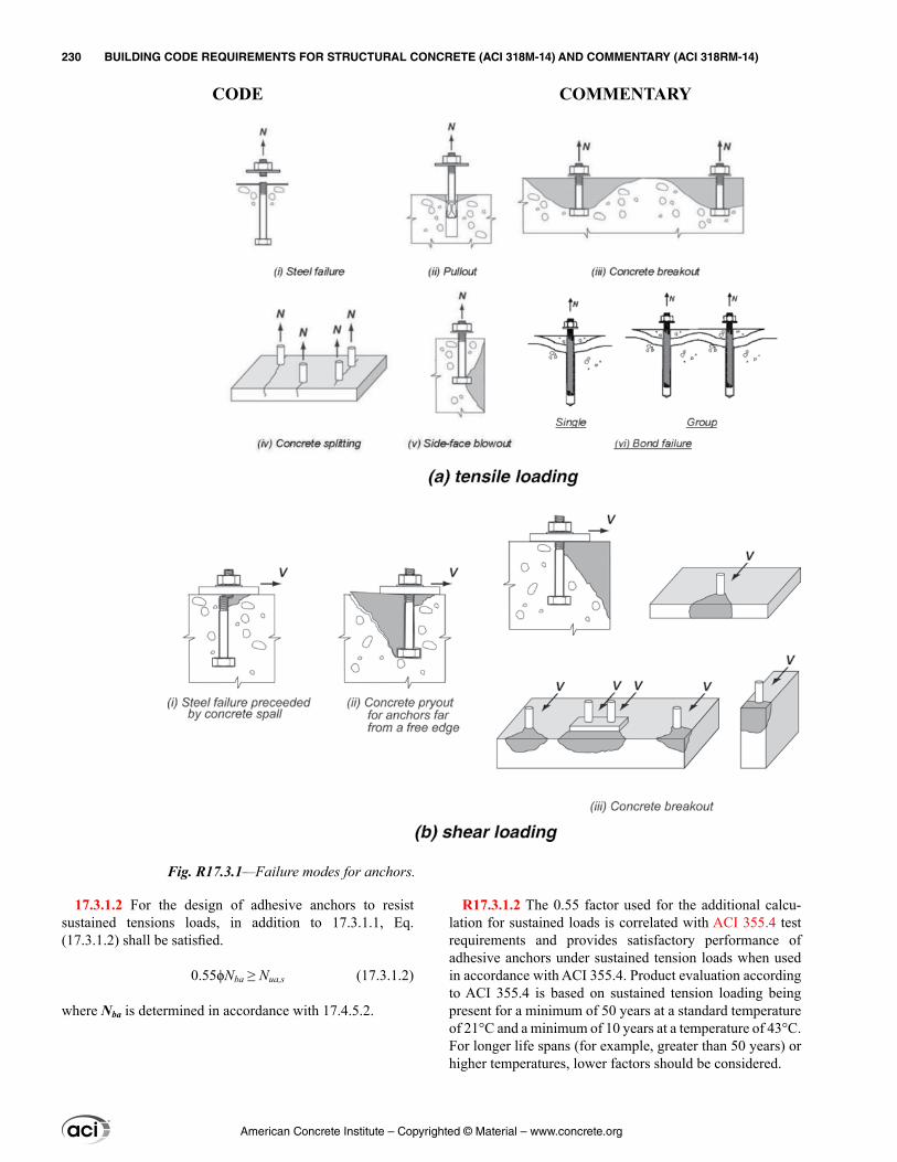
17.3.1.2 For the design of adhesive anchors to resist sustained tensions loads, in addition to 17.3.1.1, Eq. (17.3.1.2) shall be satisfied.
0.55ϕNba ≥ Nua,s (17.3.1.2)
where Nba is determined in accordance with 17.4.5.2.
R17.3.1.2 The 0.55 factor used for the additional calcu-lation for sustained loads is correlated with ACI 355.4 test requirements and provides satisfactory performance of adhesive anchors under sustained tension loads when used in accordance with ACI 355.4. Product evaluation according to ACI 355.4 is based on sustained tension loading being present for a minimum of 50 years at a standard temperature of 21°C and a minimum of 10 years at a temperature of 43°C. For longer life spans (for example, greater than 50 years) or higher temperatures, lower factors should be considered.
Fig. R17.3.1—Failure modes for anchors.
American Concrete Institute – Copyrighted © Material – www.concrete.org
230 BUILDING CODE REQUIREMENTS FOR STRUCTURAL CONCRETE (ACI 318M-14) AND COMMENTARY (ACI 318RM-14)
CODE COMMENTARY
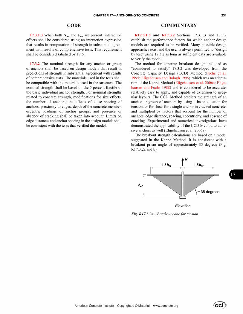
17.3.1.3 When both Nua and Vua are present, interaction effects shall be considered using an interaction expression that results in computation of strength in substantial agree-ment with results of comprehensive tests. This requirement shall be considered satisfied by 17.6.
17.3.2 The nominal strength for any anchor or group of anchors shall be based on design models that result in predictions of strength in substantial agreement with results of comprehensive tests. The materials used in the tests shall be compatible with the materials used in the structure. The nominal strength shall be based on the 5 percent fractile of the basic individual anchor strength. For nominal strengths related to concrete strength, modifications for size effects, the number of anchors, the effects of close spacing of anchors, proximity to edges, depth of the concrete member, eccentric loadings of anchor groups, and presence or absence of cracking shall be taken into account. Limits on edge distances and anchor spacing in the design models shall be consistent with the tests that verified the model.
R17.3.1.3 and R17.3.2 Sections 17.3.1.3 and 17.3.2 establish the performance factors for which anchor design models are required to be verified. Many possible design approaches exist and the user is always permitted to “design by test” using 17.3.2 as long as sufficient data are available to verify the model.
The method for concrete breakout design included as “considered to satisfy” 17.3.2 was developed from the Concrete Capacity Design (CCD) Method (Fuchs et al. 1995; Eligehausen and Balogh 1995), which was an adapta-tion of the Kappa Method (Eligehausen et al. 2006a; Elige-hausen and Fuchs 1988) and is considered to be accurate, relatively easy to apply, and capable of extension to irreg-ular layouts. The CCD Method predicts the strength of an anchor or group of anchors by using a basic equation for tension, or for shear for a single anchor in cracked concrete, and multiplied by factors that account for the number of anchors, edge distance, spacing, eccentricity, and absence of cracking. Experimental and numerical investigations have demonstrated the applicability of the CCD Method to adhe-sive anchors as well (Eligehausen et al. 2006a).
The breakout strength calculations are based on a model suggested in the Kappa Method. It is consistent with a breakout prism angle of approximately 35 degrees (Fig. R17.3.2a and b).
Fig. R17.3.2a—Breakout cone for tension.
American Concrete Institute – Copyrighted © Material – www.concrete.org
CHAPTER 17—ANCHORING TO CONCRETE 231
CODE COMMENTARY
17
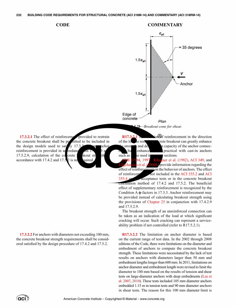
17.3.2.1 The effect of reinforcement provided to restrain the concrete breakout shall be permitted to be included in the design models used to satisfy 17.3.2. Where anchor reinforcement is provided in accordance with 17.4.2.9 and 17.5.2.9, calculation of the concrete breakout strength in accordance with 17.4.2 and 17.5.2 is not required.
17.3.2.2 For anchors with diameters not exceeding 100 mm, the concrete breakout strength requirements shall be consid-ered satisfied by the design procedure of 17.4.2 and 17.5.2.
R17.3.2.1 The addition of reinforcement in the direction of the load to restrain concrete breakout can greatly enhance the strength and deformation capacity of the anchor connec-tion. Such enhancement is practical with cast-in anchors such as those used in precast sections.
CEB (1994, 1997), Klingner et al. (1982), ACI 349, and Eligehausen et al. (2006b) provide information regarding the effect of reinforcement on the behavior of anchors. The effect of reinforcement is not included in the ACI 355.2 and ACI 355.4 anchor acceptance tests or in the concrete breakout calculation method of 17.4.2 and 17.5.2. The beneficial effect of supplementary reinforcement is recognized by the Condition A ϕ-factors in 17.3.3. Anchor reinforcement may be provided instead of calculating breakout strength using the provisions of Chapter 25 in conjunction with 17.4.2.9 and 17.5.2.9.
The breakout strength of an unreinforced connection can be taken as an indication of the load at which significant cracking will occur. Such cracking can represent a service-ability problem if not controlled (refer to R17.5.2.1).
R17.3.2.2 The limitation on anchor diameter is based on the current range of test data. In the 2002 through 2008 editions of the Code, there were limitations on the diameter and embedment of anchors to compute the concrete breakout strength. These limitations were necessitated by the lack of test results on anchors with diameters larger than 50 mm and embedment lengths longer than 600 mm. In 2011, limitations on anchor diameter and embedment length were revised to limit the diameter to 100 mm based on the results of tension and shear tests on large-diameter anchors with deep embedments (Lee et al. 2007, 2010). These tests included 105 mm diameter anchors embedded 1.15 m in tension tests and 90 mm diameter anchors in shear tests. The reason for this 100 mm diameter limit is
Fig. R17.3.2b—Breakout cone for shear.
American Concrete Institute – Copyrighted © Material – www.concrete.org
232 BUILDING CODE REQUIREMENTS FOR STRUCTURAL CONCRETE (ACI 318M-14) AND COMMENTARY (ACI 318RM-14)
CODE COMMENTARY
17.3.2.3 For adhesive anchors with embedment depths 4da ≤ hef ≤ 20da, the bond strength requirements shall be consid-ered satisfied by the design procedure of 17.4.5.
17.3.3 Strength reduction factor ϕ for anchors in concrete shall be as follows when the load combinations of 5.3 are used:
(a) Anchor governed by strength of a ductile steel element(i) Tension loads .......................................................0.75(ii) Shear loads .........................................................0.65
(b) Anchor governed by strength of a brittle steel element(i) Tension loads .......................................................0.65(ii) Shear loads .........................................................0.60
(c) Anchor governed by concrete breakout, side-face blowout, bond, pullout, or pryout strength
Condition A Condition B(i) Shear loads .........................0.75 .........................0.70
(ii) Tension loadsCast-in headed studs, headedbolts, or hooked bolts ..............0.75 .........................0.70
Post-installed anchors with category as determined from ACI 355.2 or ACI 355.4
Category 1 .................................0.75 .........................0.65(Low sensitivity to installation and high reliability)Category 2 .................................0.65 .........................0.55(Medium sensitivity to installation and medium reliability)Category 3 .................................0.55 .........................0.45(High sensitivity to installation and lower reliability)Condition A applies where supplementary reinforcement
is present except for pullout and pryout strengths.Condition B applies where supplementary reinforcement
is not present, and for pullout or pryout strength.
that the largest diameter anchor in ASTM F1554 is 100 mm, whereas other ASTM specifications permit up to 200 mm diameter anchors that have not been tested to ensure applica-bility of the 17.4.2 and 17.5.2 concrete breakout provisions.
R17.3.2.3 ACI 355.4 limits the embedment depth of adhe-sive anchors to 4da ≤ hef ≤ 20da, which represents the theo-retical limits of the bond model (Eligehausen et al. 2006a).
R17.3.3 The ϕ-factors for steel strength are based on using futa to determine the nominal strength of the anchor (refer to 17.4.1 and 17.5.1) rather than fya, as used in the design of reinforced concrete members. Although the ϕ-factors for use with futa appear low, they result in a level of safety consistent with the use of higher ϕ-factors applied to fya. The smaller ϕ-factors for shear than for tension do not reflect basic material differences but rather account for the possibility of a non-uniform distribution of shear in connec-tions with multiple anchors. It is acceptable to have a ductile failure of a steel element in the attachment if the attachment is designed so that it will undergo ductile yielding at a load level corresponding to anchor forces no greater than the minimum design strength of the anchors specified in 17.2.3 (refer to 17.2.3.4.3 and 17.2.3.5.3).
Even though the ϕ-factor for structural plain concrete is 0.60, the basic factor for brittle concrete failures (ϕ = 0.70) was chosen based on results of probabilistic studies (Farrow and Klingner 1995) that indicated the use of the ϕ-factor for structural plain concrete with mean values of concrete-controlled failures produced adequate safety levels. Because the nominal resistance expressions used in this chapter and in the test requirements are based on the 5 percent fractiles, the ϕ = 0.60 value would be overly conservative. Compar-ison with other design procedures and probabilistic studies (Farrow and Klingner 1995) indicated that the choice of ϕ = 0.70 was justified. Applications with supplementary rein-forcement (Condition A) provide more deformation capacity, permitting the ϕ-factors to be increased. The value of ϕ = 0.75 is compatible with the level of safety for shear failures in concrete beams, and has been recommended in the PCI Design Handbook (MNL 120) and by ACI 349.
For anchors governed by the more brittle concrete breakout or blowout failure, two conditions are recognized. If supple-mentary reinforcement is present (Condition A), greater deformation capacity is provided than in the case where such supplementary reinforcement is not present (Condition B). An explicit design of supplementary reinforcement is not required. However, the arrangement of supplementary rein-forcement should generally conform to that of the anchor reinforcement shown in Fig. R17.4.2.9 and R17.5.2.9b. Full development is not required.
The strength reduction factors for anchor reinforcement are given in 17.4.2.9 and 17.5.2.9.
The ACI 355.2 tests for sensitivity to installation proce-dures determine the reliability category appropriate for a particular expansion or undercut anchoring device. In the
American Concrete Institute – Copyrighted © Material – www.concrete.org
CHAPTER 17—ANCHORING TO CONCRETE 233
CODE COMMENTARY
17
17.4—Design requirements for tensile loading 17.4.1 Steel strength of anchor in tension
17.4.1.1 The nominal strength of an anchor in tension as governed by the steel, Nsa, shall be evaluated by calcula-tions based on the properties of the anchor material and the physical dimensions of the anchor.
17.4.1.2 The nominal strength of an anchor in tension, Nsa, shall not exceed
Nsa = Ase,N futa (17.4.1.2)
where Ase,N is the effective cross-sectional area of an anchor in tension, mm2, and futa shall not be taken greater than the smaller of 1.9fya and 860 MPa.
ACI 355.2 tests for expansion and undercut anchors, the effects of variability in anchor torque during installation, tolerance on drilled hole size, and energy level used in setting anchors are considered; for expansion and undercut anchors approved for use in cracked concrete, increased crack widths are considered. ACI 355.4 tests for sensitivity for installation procedures determine the category for a particular adhesive anchor system considering the influence of adhesive mixing and the influence of hole cleaning in dry, saturated, and water-filled/underwater bore holes. The three categories of acceptable post-installed anchors are:
Category 1—low sensitivity to installation and high reliability
Category 2—medium sensitivity to installation and medium reliability
Category 3—high sensitivity to installation and lower reliability
The strengths of anchors under shear loads are not as sensitive to installation errors and tolerances. Therefore, for shear calculations of all anchors, ϕ = 0.75 for Condition A and ϕ = 0.70 for Condition B.
R17.4—Design requirements for tensile loading R17.4.1 Steel strength of anchor in tension
R17.4.1.2 The nominal strength of anchors in tension is best represented as a function of futa rather than fya because the large majority of anchor materials do not exhibit a well-defined yield point. The AISC has based tension strength of anchors on Ase,N futa since the 1986 edition of their specifi-cations. The use of Eq. (17.4.1.2) with 5.3 load factors and the ϕ-factors of 17.3.3 give design strengths consistent with AISC 360.
The limitation of 1.9fya on futa is to ensure that, under service load conditions, the anchor does not exceed fya. The limit on futa of 1.9fya was determined by converting the LRFD provisions to corresponding service level conditions. For 5.3, the average load factor of 1.4 (from 1.2D + 1.6L) divided by the highest ϕ-factor (0.75 for tension) results in a limit of futa/fya of 1.4/0.75 = 1.87. Although not a concern for standard structural steel anchors (maximum value of futa/fya is 1.6 for ASTM A307), the limitation is applicable to some stainless steels.
For post-installed anchors having a reduced cross-sectional area anywhere along the anchor length, such as wedge-type anchors, the effective cross-sectional area of the anchor should be provided by the manufacturer. For threaded rods and headed bolts, ASME B1.1 defines Ase,N as
Ase,N = 2
0.97434
π− a
t
dn
American Concrete Institute – Copyrighted © Material – www.concrete.org
234 BUILDING CODE REQUIREMENTS FOR STRUCTURAL CONCRETE (ACI 318M-14) AND COMMENTARY (ACI 318RM-14)
CODE COMMENTARY
17.4.2 Concrete breakout strength of anchor in tension
17.4.2.1 The nominal concrete breakout strength in tension, Ncb of a single anchor or Ncbg of a group of anchors, shall not exceed:
(a) For a single anchor
, , ,= ψ ψ ψNccb ed N c N cp N b
Nco
AN N
A (17.4.2.1a)
(b) For a group of anchors
, , , ,= ψ ψ ψ ψNccbg ec N ed N c N cp N b
Nco
AN N
A (17.4.2.1b)
Factors ψec,N, ψed,N, ψc,N, and ψcp,N are defined in 17.4.2.4, 17.4.2.5, 17.4.2.6, and 17.4.2.7, respectively. ANc is the projected concrete failure area of a single anchor or group of anchors that shall be approximated as the base of the rectilinear geometrical figure that results from projecting the failure surface outward 1.5hef from the centerlines of the anchor, or in the case of a group of anchors, from a line through a row of adjacent anchors. ANc shall not exceed nANco, where n is the number of anchors in the group that resist tension. ANco is the projected concrete failure area of a single anchor with an edge distance equal to or greater than 1.5hef
ANco = 9hef 2 (17.4.2.1c)
where nt is the number of threads per millimeter.
R17.4.2 Concrete breakout strength of anchor in tension
R17.4.2.1 The effects of multiple anchors, spacing of anchors, and edge distance on the nominal concrete breakout strength in tension are included by applying the modification factors ANc/ANco and ψed,N in Eq. (17.4.2.1a) and (17.4.2.1b).
Figure R17.4.2.1(a) shows ANco and the development of Eq. (17.4.2.1c). ANco is the maximum projected area for a single anchor. Figure R17.4.2.1(b) shows examples of the projected areas for various single-anchor and multiple-anchor arrangements. Because ANc is the total projected area for a group of anchors, and ANco is the area for a single anchor, there is no need to include n, the number of anchors, in Eq. (17.4.2.1a) or (17.4.2.1b). If anchor groups are posi-tioned in such a way that their projected areas overlap, the value of ANc is required to be reduced accordingly.
American Concrete Institute – Copyrighted © Material – www.concrete.org
CHAPTER 17—ANCHORING TO CONCRETE 235
CODE COMMENTARY
17
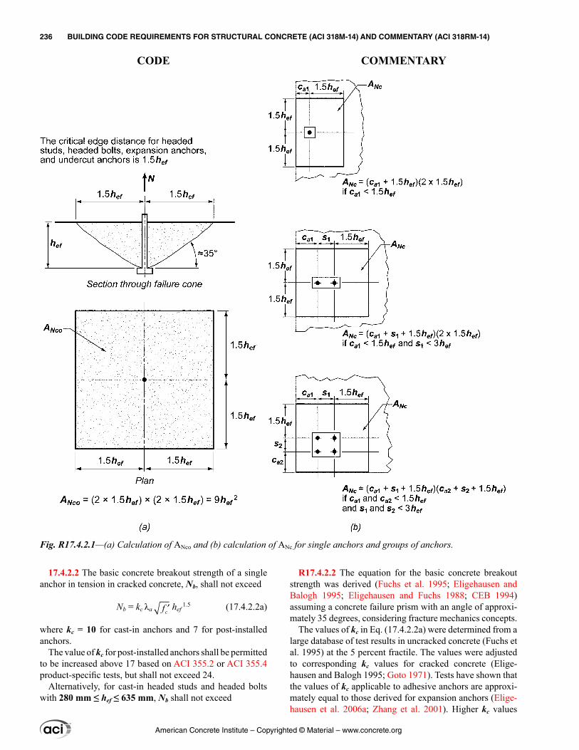
17.4.2.2 The basic concrete breakout strength of a single anchor in tension in cracked concrete, Nb, shall not exceed
Nb = kc λa ′cf hef 1.5 (17.4.2.2a)
where kc = 10 for cast-in anchors and 7 for post-installed anchors.
The value of kc for post-installed anchors shall be permitted to be increased above 17 based on ACI 355.2 or ACI 355.4 product-specific tests, but shall not exceed 24.
Alternatively, for cast-in headed studs and headed bolts with 280 mm ≤ hef ≤ 635 mm, Nb shall not exceed
R17.4.2.2 The equation for the basic concrete breakout strength was derived (Fuchs et al. 1995; Eligehausen and Balogh 1995; Eligehausen and Fuchs 1988; CEB 1994) assuming a concrete failure prism with an angle of approxi-mately 35 degrees, considering fracture mechanics concepts.
The values of kc in Eq. (17.4.2.2a) were determined from a large database of test results in uncracked concrete (Fuchs et al. 1995) at the 5 percent fractile. The values were adjusted to corresponding kc values for cracked concrete (Elige-hausen and Balogh 1995; Goto 1971). Tests have shown that the values of kc applicable to adhesive anchors are approxi-mately equal to those derived for expansion anchors (Elige-hausen et al. 2006a; Zhang et al. 2001). Higher kc values
Fig. R17.4.2.1—(a) Calculation of ANco and (b) calculation of ANc for single anchors and groups of anchors.
American Concrete Institute – Copyrighted © Material – www.concrete.org
236 BUILDING CODE REQUIREMENTS FOR STRUCTURAL CONCRETE (ACI 318M-14) AND COMMENTARY (ACI 318RM-14)
CODE COMMENTARY
Nb = 3.9λa ′cf hef 5/3 (17.4.2.2b)
17.4.2.3 Where anchors are located less than 1.5hef from three or more edges, the value of hef used for the calcula-tion of ANc in accordance with 17.4.2.1, as well as for the equations in 17.4.2.1 through 17.4.2.5, shall be the larger of (ca,max)/1.5 and s/3, where s is the maximum spacing between anchors within the group.
for post-installed anchors may be permitted, provided they have been determined from testing in accordance with ACI 355.2 or ACI 355.4. For anchors with a deeper embedment (hef > 280 mm), test evidence indicates the use of hef
1.5 can be overly conservative for some cases. An alternative expression (Eq. (17.4.2.2b)) is provided using hef
5/3 for evaluation of cast-in headed studs and headed bolts with 280 mm ≤ hef ≤ 635 mm. This expression can also be appropriate for some undercut post-installed anchors. However, for such anchors, the use of Eq. (17.4.2.2b) should be justified by test results in accordance with 17.3.2. Experimental and numerical inves-tigation indicate that Eq. (17.4.2.2b) may be unconservative for hef > 635 mm where bearing pressure on the anchor head is at or near the limit permitted by Eq. (17.4.3.4) (Ožbolt et al. 2007).
R17.4.2.3 For anchors located less than 1.5hef from three or more edges, the tensile breakout strength calculated by the CCD Method (refer to R17.3.2), which is the basis for the equations in 17.4.2.1 through 17.4.2.5, gives overly conservative results (Lutz 1995). This occurs because the ordinary definitions of ANc/ANco do not correctly reflect the edge effects. This problem is corrected by limiting the value of hef used in the equations in 17.4.2.1 through 17.4.2.5 to (ca,max)/1.5, where ca,max is the largest of the influencing edge distances that are less than or equal to the actual 1.5hef. In no case should (ca,max)/1.5 be taken less than one-third of the maximum spacing between anchors within the group. The limit on hef of at least one-third of the maximum spacing between anchors within the group prevents the use of a calculated strength based on individual breakout prisms for a group anchor configuration.
This approach is illustrated in Fig. R17.4.2.3. In this example, the proposed limit on the value of hef to be used in the computations where hef = (ca,max)/1.5, results in hef = h′ef = 100 mm. For this example, this would be the proper value to be used for hef in computing the resistance even if the actual embedment depth is larger.
The requirement of 17.4.2.3 may be visualized by moving the actual concrete breakout surface, which originates at the actual hef, toward the surface of the concrete parallel to the applied tension load. The value of hef used in equations in 17.4.2.1 through 17.4.2.5 is determined when either: (a) the outer boundaries of the failure surface first intersect a free edge; or (b) the intersection of the breakout surface between anchors within the group first intersects the surface of the concrete. For the example shown in Fig. R17.4.2.3, Point A defines the intersection of the assumed failure surface for limiting hef with the concrete surface.
American Concrete Institute – Copyrighted © Material – www.concrete.org
CHAPTER 17—ANCHORING TO CONCRETE 237
CODE COMMENTARY
17
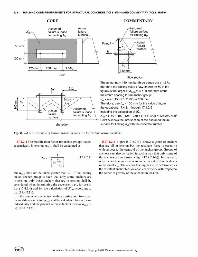
17.4.2.4 The modification factor for anchor groups loaded eccentrically in tension, ψec,N, shall be calculated as
,12
13
ψ = ′+
ec N
N
ef
eh
(17.4.2.4)
but ψec,N shall not be taken greater than 1.0. If the loading on an anchor group is such that only some anchors are in tension, only those anchors that are in tension shall be considered when determining the eccentricity e′N for use in Eq. (17.4.2.4) and for the calculation of Ncbg according to Eq. (17.4.2.1b).
In the case where eccentric loading exists about two axes, the modification factor ψec,N shall be calculated for each axis individually and the product of these factors used as ψec,N in Eq. (17.4.2.1b).
R17.4.2.4 Figure R17.4.2.4(a) shows a group of anchors that are all in tension but the resultant force is eccentric with respect to the centroid of the anchor group. Groups of anchors can also be loaded in such a way that only some of the anchors are in tension (Fig. R17.4.2.4(b)). In this case, only the anchors in tension are to be considered in the deter-mination of e′N. The anchor loading has to be determined as the resultant anchor tension at an eccentricity with respect to the center of gravity of the anchors in tension.
Fig. R17.4.2.3—Example of tension where anchors are located in narrow members.
American Concrete Institute – Copyrighted © Material – www.concrete.org
238 BUILDING CODE REQUIREMENTS FOR STRUCTURAL CONCRETE (ACI 318M-14) AND COMMENTARY (ACI 318RM-14)
CODE COMMENTARY
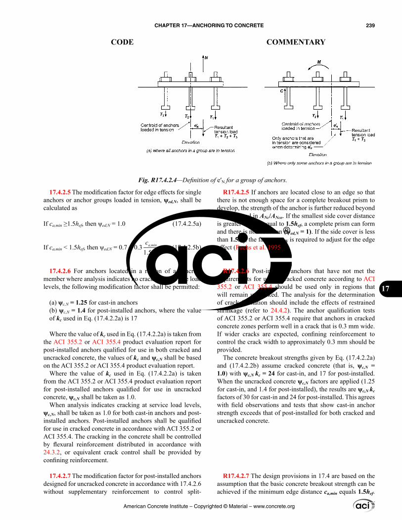
17.4.2.5 The modification factor for edge effects for single anchors or anchor groups loaded in tension, ψed,N, shall be calculated as
If ca,min ≥1.5hef, then ψed,N = 1.0 (17.4.2.5a)
If ca,min < 1.5hef, then ψed,N = 0.7 + 0.31.5
a,min
ef
ch
(17.4.2.5b)
17.4.2.6 For anchors located in a region of a concrete member where analysis indicates no cracking at service load levels, the following modification factor shall be permitted:
(a) ψc,N = 1.25 for cast-in anchors(b) ψc,N = 1.4 for post-installed anchors, where the value of kc used in Eq. (17.4.2.2a) is 17
Where the value of kc used in Eq. (17.4.2.2a) is taken from the ACI 355.2 or ACI 355.4 product evaluation report for post-installed anchors qualified for use in both cracked and uncracked concrete, the values of kc and ψc,N shall be based on the ACI 355.2 or ACI 355.4 product evaluation report.
Where the value of kc used in Eq. (17.4.2.2a) is taken from the ACI 355.2 or ACI 355.4 product evaluation report for post-installed anchors qualified for use in uncracked concrete, ψc,N shall be taken as 1.0.
When analysis indicates cracking at service load levels, ψc,N, shall be taken as 1.0 for both cast-in anchors and post-installed anchors. Post-installed anchors shall be qualified for use in cracked concrete in accordance with ACI 355.2 or ACI 355.4. The cracking in the concrete shall be controlled by flexural reinforcement distributed in accordance with 24.3.2, or equivalent crack control shall be provided by confining reinforcement.
17.4.2.7 The modification factor for post-installed anchors designed for uncracked concrete in accordance with 17.4.2.6 without supplementary reinforcement to control split-
R17.4.2.5 If anchors are located close to an edge so that there is not enough space for a complete breakout prism to develop, the strength of the anchor is further reduced beyond that reflected in ANc/ANco. If the smallest side cover distance is greater than or equal to 1.5hef, a complete prism can form and there is no reduction (ψed,N = 1). If the side cover is less than 1.5hef, the factor ψed,N is required to adjust for the edge effect (Fuchs et al. 1995).
R17.4.2.6 Post-installed anchors that have not met the requirements for use in cracked concrete according to ACI 355.2 or ACI 355.4 should be used only in regions that will remain uncracked. The analysis for the determination of crack formation should include the effects of restrained shrinkage (refer to 24.4.2). The anchor qualification tests of ACI 355.2 or ACI 355.4 require that anchors in cracked concrete zones perform well in a crack that is 0.3 mm wide. If wider cracks are expected, confining reinforcement to control the crack width to approximately 0.3 mm should be provided.
The concrete breakout strengths given by Eq. (17.4.2.2a) and (17.4.2.2b) assume cracked concrete (that is, ψc,N = 1.0) with ψc,N kc = 24 for cast-in, and 17 for post-installed. When the uncracked concrete ψc,N factors are applied (1.25 for cast-in, and 1.4 for post-installed), the results are ψc,N kc factors of 30 for cast-in and 24 for post-installed. This agrees with field observations and tests that show cast-in anchor strength exceeds that of post-installed for both cracked and uncracked concrete.
R17.4.2.7 The design provisions in 17.4 are based on the assumption that the basic concrete breakout strength can be achieved if the minimum edge distance ca,min equals 1.5hef.
Fig. R17.4.2.4—Definition of e′N for a group of anchors.
American Concrete Institute – Copyrighted © Material – www.concrete.org
CHAPTER 17—ANCHORING TO CONCRETE 239
CODE COMMENTARY
17
Test results (Asmus 1999), however, indicate that many torque-controlled and displacement-controlled expansion anchors and some undercut anchors require minimum edge distances exceeding 1.5hef to achieve the basic concrete breakout strength when tested in uncracked concrete without supplementary reinforcement to control splitting. When a tension load is applied, the resulting tensile stresses at the embedded end of the anchor are added to the tensile stresses induced due to anchor installation, and splitting failure may occur before reaching the concrete breakout strength defined in 17.4.2.1. To account for this potential splitting mode of failure, the basic concrete breakout strength is reduced by a factor ψcp,N if ca,min is less than the critical edge distance cac. If supplementary reinforcement to control splitting is present or if the anchors are located in a region where analysis indicates cracking of the concrete at service loads, then the reduction factor ψcp,N is taken as 1.0. The presence of supplementary reinforcement to control splitting does not affect the selection of Condition A or B in 17.3.3.
R17.4.2.9 For conditions where the factored tensile force exceeds the concrete breakout strength of the anchor(s) or where the breakout strength is not evaluated, the nominal strength can be that of anchor reinforcement properly anchored, as illustrated in Fig. R17.4.2.9. Care needs to be taken in the selection and positioning of the anchor rein-forcement. The anchor reinforcement should consist of stir-rups, ties, or hairpins placed as close as practicable to the anchor. Only reinforcement spaced less than 0.5hef from the anchor centerline should be included as anchor reinforce-ment. The research (Eligehausen et al. 2006b) on which these provisions is based was limited to anchor reinforce-ment with maximum diameter similar to a No. 16 bar. It is beneficial for the anchor reinforcement to enclose the surface reinforcement. In sizing the anchor reinforcement, use of a 0.75 strength reduction factor ϕ is recommended as is used for strut-and-tie models. As a practical matter, use of anchor reinforcement is generally limited to cast-in anchors.
ting, ψcp,N, shall be calculated as follows using the critical distance cac as defined in 17.7.6
If ca,min ≥ cac, then ψcp,N = 1.0 (17.4.2.7a)
If ca,min < cac, then ψcp,N = a,min
ac
cc
(17.4.2.7b)
but ψcp,N determined from Eq. (17.4.2.7b) shall not be taken less than 1.5hef /cac, where the critical distance cac is defined in 17.7.6.
For all other cases, including cast-in anchors, ψcp,N shall be taken as 1.0.
17.4.2.8 Where an additional plate or washer is added at the head of the anchor, it shall be permitted to calculate the projected area of the failure surface by projecting the failure surface outward 1.5hef from the effective perimeter of the plate or washer. The effective perimeter shall not exceed the value at a section projected outward more than the thickness of the washer or plate from the outer edge of the head of the anchor.
17.4.2.9 Where anchor reinforcement is developed in accordance with Chapter 25 on both sides of the breakout surface, the design strength of the anchor reinforcement shall be permitted to be used instead of the concrete breakout strength in determining ϕNn. A strength reduction factor of 0.75 shall be used in the design of the anchor reinforcement.
American Concrete Institute – Copyrighted © Material – www.concrete.org
240 BUILDING CODE REQUIREMENTS FOR STRUCTURAL CONCRETE (ACI 318M-14) AND COMMENTARY (ACI 318RM-14)
CODE COMMENTARY
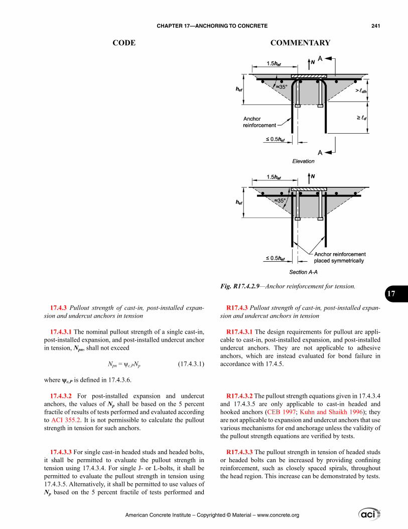
17.4.3 Pullout strength of cast-in, post-installed expan-sion and undercut anchors in tension
17.4.3.1 The nominal pullout strength of a single cast-in, post-installed expansion, and post-installed undercut anchor in tension, Npn, shall not exceed
Npn = ψc,PNp (17.4.3.1)
where ψc,P is defined in 17.4.3.6.
17.4.3.2 For post-installed expansion and undercut anchors, the values of Np shall be based on the 5 percent fractile of results of tests performed and evaluated according to ACI 355.2. It is not permissible to calculate the pullout strength in tension for such anchors.
17.4.3.3 For single cast-in headed studs and headed bolts, it shall be permitted to evaluate the pullout strength in tension using 17.4.3.4. For single J- or L-bolts, it shall be permitted to evaluate the pullout strength in tension using 17.4.3.5. Alternatively, it shall be permitted to use values of Np based on the 5 percent fractile of tests performed and
R17.4.3 Pullout strength of cast-in, post-installed expan-sion and undercut anchors in tension
R17.4.3.1 The design requirements for pullout are appli-cable to cast-in, post-installed expansion, and post-installed undercut anchors. They are not applicable to adhesive anchors, which are instead evaluated for bond failure in accordance with 17.4.5.
R17.4.3.2 The pullout strength equations given in 17.4.3.4 and 17.4.3.5 are only applicable to cast-in headed and hooked anchors (CEB 1997; Kuhn and Shaikh 1996); they are not applicable to expansion and undercut anchors that use various mechanisms for end anchorage unless the validity of the pullout strength equations are verified by tests.
R17.4.3.3 The pullout strength in tension of headed studs or headed bolts can be increased by providing confining reinforcement, such as closely spaced spirals, throughout the head region. This increase can be demonstrated by tests.
Fig. R17.4.2.9—Anchor reinforcement for tension.
American Concrete Institute – Copyrighted © Material – www.concrete.org
CHAPTER 17—ANCHORING TO CONCRETE 241
CODE COMMENTARY
17
evaluated in the same manner as the ACI 355.2 procedures but without the benefit of friction.
17.4.3.4 The pullout strength in tension of a single headed stud or headed bolt, Np, for use in Eq. (17.4.3.1), shall not exceed
Np = 8Abrg fc′ (17.4.3.4)
17.4.3.5 The pullout strength in tension of a single hooked bolt, Np, for use in Eq. (17.4.3.1) shall not exceed
Np = 0.9fc′ehda (17.4.3.5)
where 3da ≤ eh ≤ 4.5da.
17.4.3.6 For an anchor located in a region of a concrete member where analysis indicates no cracking at service load levels, the following modification factor shall be permitted
ψc,P = 1.4
Where analysis indicates cracking at service load levels, ψc,P shall be taken as 1.0.
17.4.4 Concrete side-face blowout strength of a headed anchor in tension
17.4.4.1 For a single headed anchor with deep embedment close to an edge (hef > 2.5ca1), the nominal side-face blowout strength, Nsb, shall not exceed
Nsb = 13ca1 brgA λa ′cf (17.4.4.1)
If ca2 for the single headed anchor is less than 3ca1, the value of Nsb shall be multiplied by the factor (1 + ca2/ca1)/4, where 1.0 ≤ ca2/ca1 ≤ 3.0.
17.4.4.2 For multiple headed anchors with deep embed-ment close to an edge (hef > 2.5ca1) and anchor spacing less than 6ca1, the nominal strength of those anchors susceptible to a side-face blowout failure Nsbg shall not exceed
Nsbg = 1
16
+ a
sc
Nsb (17.4.4.2)
where s is the distance between the outer anchors along the edge, and Nsb is obtained from Eq. (17.4.4.1) without modi-fication for a perpendicular edge distance.
R17.4.3.4 The value calculated from Eq. (17.4.3.4) corre-sponds to the load at which crushing of the concrete occurs due to bearing of the anchor head (CEB 1997; ACI 349). It is not the load required to pull the anchor completely out of the concrete, so the equation contains no term relating to embedment depth. Local crushing of the concrete greatly reduces the stiffness of the connection, and generally will be the beginning of a pullout failure.
R17.4.3.5 Equation (17.4.3.5) for hooked bolts was developed by Lutz based on the results of Kuhn and Shaikh (1996). Reliance is placed on the bearing component only, neglecting any frictional component because crushing inside the hook will greatly reduce the stiffness of the connection and generally will be the beginning of pullout failure. The limits on eh are based on the range of variables used in the three tests programs reported in Kuhn and Shaikh (1996).
R17.4.4 Concrete side-face blowout strength of a headed anchor in tension—The design requirements for side-face blowout are based on the recommendations of Furche and Eligehausen (1991). These requirements are applicable to headed anchors that usually are cast-in anchors. Splitting during installation rather than side-face blowout generally governs post-installed anchors, and is evaluated by the ACI 355.2 requirements.
R17.4.4.2 In determining nominal side-face blowout strength for multiple headed anchors, only those anchors close to an edge (hef > 2.5ca1) that are loaded in tension should be considered. Their strength should be compared to the proportion of the tensile load applied to those anchors.
American Concrete Institute – Copyrighted © Material – www.concrete.org
242 BUILDING CODE REQUIREMENTS FOR STRUCTURAL CONCRETE (ACI 318M-14) AND COMMENTARY (ACI 318RM-14)
CODE COMMENTARY
17.4.5 Bond strength of adhesive anchor in tension
17.4.5.1 The nominal bond strength in tension, Na of a single adhesive anchor or Nag of a group of adhesive anchors, shall not exceed
(a) For a single adhesive anchor:
, ,= ψ ψNaa ed Na cp Na ba
Nao
AN N
A (17.4.5.1a)
(b) For a group of adhesive anchors:
, , ,= ψ ψ ψNaag ec Na ed Na cp Na ba
Nao
AN N
A (17.4.5.1b)
Factors ψec,Na, ψed,Na, and ψcp,Na are defined in 17.4.5.3, 17.4.5.4, and 17.4.5.5, respectively. ANa is the projected influence area of a single adhesive anchor or group of adhe-sive anchors that shall be approximated as a rectilinear area that projects outward a distance cNa from the centerline of the adhesive anchor, or in the case of a group of adhesive anchors, from a line through a row of adjacent adhesive anchors. ANa shall not exceed nANao, where n is the number of adhesive anchors in the group that resist tension loads. ANao is the projected influence area of a single adhesive anchor with an edge distance equal to or greater than cNa:
ANao = (2cNa)2 (17.4.5.1c)
where
cNa = 10da7.6τuncr (17.4.5.1d)
and constant 7.6 carries the unit of MPa.
R17.4.5 Bond strength of adhesive anchor in tension
R17.4.5.1 Evaluation of bond strength applies only to adhe-sive anchors. Single anchors with small embedment loaded to failure in tension may exhibit concrete breakout failures, while deeper embedments produce bond failures. Adhesive anchors that exhibit bond failures when loaded individually may exhibit concrete failures when in a group or in a near-edge condition. In all cases, the strength in tension of adhe-sive anchors is limited by the concrete breakout strength as given by Eq. (17.4.2.1a) and (17.4.2.1b) (Eligehausen et al. 2006a). The influences of anchor spacing and edge distance on both bond strength and concrete breakout strength must be evaluated for adhesive anchors. The influences of anchor spacing and edge distance on the nominal bond strength of adhesive anchors in tension are included in the modification factors ANa/ANao and ψed,Na in Eq. (17.4.5.1a) and (17.4.5.1b).
The influence of nearby edges and adjacent loaded anchors on bond strength is dependent on the volume of concrete mobilized by a single adhesive anchor. In contrast to the projected concrete failure area concept used in Eq. (17.4.2.1a) and (17.4.2.1b) to compute the breakout strength of an adhesive anchor, the influence area associated with the bond strength of an adhesive anchor used in Eq. (17.4.5.1a) and (17.4.5.1b) is not a function of the embedment depth, but rather a function of the anchor diameter and the char-acteristic bond stress. The critical distance cNa is assumed the same whether the concrete is cracked or uncracked; for simplicity, the relationship for cNa in Eq. (17.4.5.1d) uses τuncr, the characteristic bond stress in uncracked concrete. This has been verified by experimental and numerical studies (Eligehausen et al. 2006a). Figure R17.4.5.1(a) shows ANao and the development of Eq. (17.4.5.1c). ANao is the projected influence area for the bond strength of a single adhesive anchor. Figure R17.4.5.1(b) shows an example of the projected influence area for an anchor group. Because, in this case, ANa is the projected influence area for a group of anchors, and ANao is the projected influence area for a single anchor, there is no need to include n, the number of anchors, in Eq. (17.4.5.1b). If anchors in a group (anchors loaded by a common base plate or attachment) are positioned in such a way that the projected influence areas of the individual anchors overlap, the value of ANa is less than nANao.
The tensile strength of closely spaced adhesive anchors with low bond strength may significantly exceed the value given by Eq. (17.4.5.1b). A correction factor is given in the literature (Eligehausen et al. 2006a) to address this issue, but for simplicity, this factor is not included in the Code.
American Concrete Institute – Copyrighted © Material – www.concrete.org
CHAPTER 17—ANCHORING TO CONCRETE 243
CODE COMMENTARY
17

17.4.5.2 The basic bond strength of a single adhesive anchor in tension in cracked concrete, Nba, shall not exceed
Nba = λa τcr πda hef (17.4.5.2)
The characteristic bond stress τcr shall be taken as the 5 percent fractile of results of tests performed and evaluated according to ACI 355.4.
Where analysis indicates cracking at service load levels, adhesive anchors shall be qualified for use in cracked concrete in accordance with ACI 355.4.
For adhesive anchors located in a region of a concrete member where analysis indicates no cracking at service load levels, τuncr shall be permitted to be used in place of τcr in Eq. (17.4.5.2) and shall be taken as the 5 percent fractile of results of tests performed and evaluated according to ACI 355.4.
R17.4.5.2 The equation for basic bond strength of adhe-sive anchors as given in Eq. (17.4.5.2) represents a uniform bond stress model that has been shown to provide the best prediction of adhesive anchor bond strength through numer-ical studies and comparisons of different models to an inter-national database of experimental results (Cook et al. 1998). The basic bond strength is valid for bond failures that occur between the concrete and the adhesive as well as between the anchor and the adhesive.
Characteristic bond stresses should be based on tests performed in accordance with ACI 355.4 and should reflect the particular combination of installation and use conditions anticipated during construction and during the anchor service life. For those cases where product-specific information is unavailable at the time of design, Table 17.4.5.2 provides lower-bound default values. The characteristic bond stresses
Fig. R17.4.5.1—Calculation of influence areas ANao and ANa.
American Concrete Institute – Copyrighted © Material – www.concrete.org
244 BUILDING CODE REQUIREMENTS FOR STRUCTURAL CONCRETE (ACI 318M-14) AND COMMENTARY (ACI 318RM-14)
CODE COMMENTARY
in Table 17.4.5.2 are the minimum values permitted for adhe-sive anchor systems qualified in accordance with ACI 355.4 for the tabulated installation and use conditions. Use of these values is restricted to the combinations of specific conditions listed; values for other combinations of installation and use conditions should not be inferred. Where both sustained loading and earthquake loading are present, the applicable factors given in the footnotes of Table 17.4.5.2 should be multiplied together. The table assumes that all concrete has a minimum age of 21 days and a minimum concrete compres-sive strength of 17 MPa. See R17.1.2.
The terms “indoor” and “outdoor” as used in Table 17.4.5.2 refer to a specific set of installation and service environments. Indoor conditions represent anchors installed in dry concrete with a rotary impact drill or rock drill and subjected to limited concrete temperature variations over the service life of the anchor. Outdoor conditions are assumed to occur, when at the time of anchor installation, the concrete is exposed to weather and may therefore be wet. Anchors installed in outdoor conditions are also assumed to be subject to greater concrete temperature variations such as might be associated with freezing and thawing or elevated temperatures resulting from direct sun exposure. While the indoor/outdoor characterization is useful for many applica-tions, there may be situations in which a literal interpreta-tion of the terms “indoor” and “outdoor” do not apply. For example, anchors installed before the building envelope is completed may involve drilling in saturated concrete. As such, the minimum characteristic bond stress associated with the outdoor condition in Table 17.4.5.2 applies, regardless of whether the service environment is “indoor” or “outdoor.” Rotary impact drills and rock drills produce non-uniform hole geometries that are generally favorable for bond. Instal-lation of adhesive anchors in core-drilled holes may result in substantially lower characteristic bond stresses. Because this effect is highly product dependent, design of anchors to be installed in core-drilled holes should adhere to the product-specific characteristic bond stresses established through testing in accordance with ACI 355.4.
The characteristic bond stresses associated with specific adhesive anchor systems are dependent on a number of parameters. Consequently, care should be taken to include all parameters relevant to the value of characteristic bond stress used in the design. These parameters include but are not limited to:
(a) Type and duration of loading—bond strength is reduced for sustained tension loading(b) Concrete cracking—bond strength is higher in uncracked concrete(c) Anchor size—bond strength is generally inversely proportional to anchor diameter(d) Drilling method—bond strength may be lower for anchors installed in core-drilled holes
It shall be permitted to use the minimum characteristic bond stress values in Table 17.4.5.2, provided (a) through (e) are satisfied:
(a) Anchors shall meet the requirements of ACI 355.4(b) Anchors shall be installed in holes drilled with a rotary impact drill or rock drill(c) Concrete at time of anchor installation shall have a minimum compressive strength of 17 MPa(d) Concrete at time of anchor installation shall have a minimum age of 21 days(e) Concrete temperature at time of anchor installation shall be at least 10°C
Table 17.4.5.2—Minimum characteristic bond stresses[1][2]
Installation and service
environment
Moisture content of concrete at time of anchor installation
Peak in-service temperature of
concrete, °Cτcr,
MPaτuncr, MPa
Outdoor Dry to fully saturated 79 1.4 4.5
Indoor Dry 43 2.1 7.0[1]Where anchor design includes sustained tension loading, multiply values of τcr and τuncr by 0.4.[2]Where anchor design includes earthquake loads for structures assigned to SDC C, D, E, or F, multiply values of τcr by 0.8 and τuncr by 0.4.
American Concrete Institute – Copyrighted © Material – www.concrete.org
CHAPTER 17—ANCHORING TO CONCRETE 245
CODE COMMENTARY
17
17.4.5.3 The modification factor for adhesive anchor groups loaded eccentrically in tension, ψec,Na, shall be calcu-lated as:
ψec,Na = 1
1 ′+
N
Na
ec
(17.4.5.3)
but ψec,Na shall not be taken greater than 1.0.If the loading on an adhesive anchor group is such that
only some adhesive anchors are in tension, only those adhe-sive anchors that are in tension shall be considered when determining the eccentricity e′N for use in Eq. (17.4.5.3) and for the calculation of Nag according to Eq. (17.4.5.1b).
In the case where eccentric loading exists about two orthogonal axes, the modification factor ψec,Na shall be calculated for each axis individually and the product of these factors used as ψec,Na in Eq. (17.4.5.1b).
(e) Degree of concrete saturation at time of hole drilling and anchor installation—bond strength may be reduced due to concrete saturation(f) Concrete temperature at time of installation—installa-tion of anchors in cold conditions may result in retarded adhesive cure and reduced bond strength(g) Concrete age at time of installation—installation in early-age concrete may result in reduced bond strength (refer to R17.1.2)(h) Peak concrete temperatures during anchor service life—under specific conditions (for example, anchors in thin concrete members exposed to direct sunlight), elevated concrete temperatures can result in reduced bond strength(i) Chemical exposure—anchors used in industrial envi-ronments may be exposed to increased levels of contami-nants that can reduce bond strength over time
Anchors tested and assessed under ACI 355.4 may in some cases not be qualified for all of the installation and service environments represented in Table 17.4.5.2. Therefore, even where the minimum values given in Table 17.4.5.2 are used for design, the relevant installation and service envi-ronments should be specified in accordance with 17.8.2.1, and only anchors that have been qualified under ACI 355.4 for the installation and service environments corresponding to the characteristic bond stress taken from Table 17.4.5.2 should be specified.
Characteristic bond stresses associated with qualified adhesive anchor systems for a specific set of installation and use conditions may substantially exceed the minimum values provided in Table 17.4.5.2. For example, 13 mm to 20 mm diameter anchors installed in impact-drilled holes in dry concrete where use is limited to indoor conditions in uncracked concrete as described above may exhibit charac-teristic bond stresses τuncr in the range of 14 to 17 MPa.
R17.4.5.3 Refer to R17.4.2.4.
American Concrete Institute – Copyrighted © Material – www.concrete.org
246 BUILDING CODE REQUIREMENTS FOR STRUCTURAL CONCRETE (ACI 318M-14) AND COMMENTARY (ACI 318RM-14)
CODE COMMENTARY
17.4.5.4 The modification factor for edge effects for single adhesive anchors or adhesive anchor groups loaded in tension, ψed,Na, shall be calculated as
If ca,min ≥ cNa, then ψed,Na = 1.0 (17.4.5.4a)
If ca,min < cNa, then ψed,Na = 0.7 + 0.3 a,min
Na
cc
(17.4.5.4b)
17.4.5.5 The modification factor for adhesive anchors designed for uncracked concrete in accordance with 17.4.5.2 without supplementary reinforcement to control splitting, ψcp,Na, shall be calculated as:
If ca,min ≥ cac, then ψcp,Na = 1.0 (17.4.5.5a)
If ca,min < cac, then ψcp,Na = a,min
ac
cc
(17.4.5.5b)
but ψcp,Na determined from Eq. (17.4.5.5b) shall not be taken less than cNa/cac, where the critical edge distance cac is defined in 17.7.6. For all other cases, ψcp,Na shall be taken as 1.0.
17.5—Design requirements for shear loading 17.5.1 Steel strength of anchor in shear
17.5.1.1 The nominal strength of an anchor in shear as governed by steel, Vsa, shall be evaluated by calculations based on the properties of the anchor material and the phys-ical dimensions of the anchor. Where concrete breakout is a potential failure mode, the required steel shear strength shall be consistent with the assumed breakout surface.
17.5.1.2 The nominal strength of an anchor in shear, Vsa, shall not exceed (a) through (c):
(a) For cast-in headed stud anchor
Vsa = Ase,V futa (17.5.1.2a)
where Ase,V is the effective cross-sectional area of an anchor in shear, mm2, and futa shall not be taken greater than the smaller of 1.9fya and 860 MPa.(b) For cast-in headed bolt and hooked bolt anchors and for post-installed anchors where sleeves do not extend through the shear plane
Vsa = 0.6Ase,V futa (17.5.1.2b)
where Ase,V is the effective cross-sectional area of an anchor in shear, mm2, and futa shall not be taken greater than the smaller of 1.9fya and 860 MPa.
(c) For post-installed anchors where sleeves extend through the shear plane, Vsa shall be based on the results
R17.4.5.4 If anchors are located close to an edge, their strength is further reduced beyond that reflected in ANa/ANao. If the smallest side cover distance is greater than or equal to cNa, there is no reduction (ψed,Na = 1). If the side cover is less than cNa, the factor ψed,Na accounts for the edge effect (Fuchs et al. 1995; Eligehausen et al. 2006a).
R17.5—Design requirements for shear loading R17.5.1 Steel strength of anchor in shear
R17.5.1.1 The shear load applied to each anchor in a group may vary depending on assumptions for the concrete breakout surface and load redistribution (refer to R17.5.2.1).
R17.5.1.2 The nominal shear strength of anchors is best represented as a function of futa rather than fya because the large majority of anchor materials do not exhibit a well-defined yield point. Welded studs develop a higher steel shear strength than headed anchors due to the fixity provided by the weld between the studs and the base plate. The use of Eq. (17.5.1.2a) and (17.5.1.2b) with 5.3 load factors and the ϕ-factors of 17.3.3 give design strengths consistent with AISC 360.
The limitation of 1.9fya on futa is to ensure that, under service load conditions, the anchor stress does not exceed fya. The limit on futa of 1.9fya was determined by converting the LRFD provisions to corresponding service level condi-tions, as discussed in R17.4.1.2.
For post-installed anchors having a reduced cross-sectional area anywhere along the anchor length, the effec-tive cross-sectional area of the anchor should be provided by the manufacturer. For threaded rods and headed bolts, ASME B1.1 defines Ase,V as
Ase,V = 2
0.97434
π− a
t
dn
American Concrete Institute – Copyrighted © Material – www.concrete.org
CHAPTER 17—ANCHORING TO CONCRETE 247
CODE COMMENTARY
17
of tests performed and evaluated according to ACI 355.2. Alternatively, Eq. (17.5.1.2b) shall be permitted to be used.
17.5.1.3 Where anchors are used with built-up grout pads, the nominal strengths of 17.5.1.2 shall be multiplied by a factor 0.80.
17.5.2 Concrete breakout strength of anchor in shear
17.5.2.1 The nominal concrete breakout strength in shear, Vcb of a single anchor or Vcbg of a group of anchors, shall not exceed:
(a) For shear force perpendicular to the edge on a single anchor
, , ,= ψ ψ ψVccb ed V c V h V b
Vco
AV V
A (17.5.2.1a)
(b) For shear force perpendicular to the edge on a group of anchors
, , , ,= ψ ψ ψ ψVccbg ec V ed V c V h V b
Vco
AV V
A (17.5.2.1b)
(c) For shear force parallel to an edge, Vcb or Vcbg shall be permitted to be twice the value of the shear force deter-mined from Eq. (17.5.2.1a) or (17.5.2.1b), respectively, with the shear force assumed to act perpendicular to the edge and with ψed,V taken equal to 1.0.(d) For anchors located at a corner, the limiting nominal concrete breakout strength shall be determined for each edge, and the minimum value shall be used.
Factors ψec,V, ψed,V, ψc,V, and ψh,V are defined in 17.5.2.5, 17.5.2.6, 17.5.2.7, and 17.5.2.8, respectively. Vb is the basic concrete breakout strength value for a single anchor. AVc is the projected area of the failure surface on the side of the concrete member at its edge for a single anchor or a group of anchors. It shall be permitted to evaluate AVc as the base of a truncated half-pyramid projected on the side face of the member where the top of the half-pyramid is given by the axis of the anchor row selected as critical. The value of ca1 shall be taken as the distance from the edge to this axis. AVc shall not exceed nAVco, where n is the number of anchors in the group.
AVco is the projected area for a single anchor in a deep member with a distance from edges equal or greater than 1.5ca1 in the direction perpendicular to the shear force. It shall be permitted to evaluate AVco as the base of a half-pyramid with a side length parallel to the edge of 3ca1 and a depth of 1.5ca1
AVco = 4.5(ca1)2 (17.5.2.1c)
where nt is the number of threads per inch.
R17.5.2 Concrete breakout strength of anchor in shear
R17.5.2.1 The shear strength equations were developed from the CCD Method (refer to R17.3.2). They assume a breakout cone angle of approximately 35 degrees (refer to Fig. R17.3.2b) and consider fracture mechanics theory. The effects of multiple anchors, spacing of anchors, edge distance, and thickness of the concrete member on nominal concrete breakout strength in shear are included by applying the reduction factor of AVc/AVco in Eq. (17.5.2.1a) and (17.5.2.1b), and ψec,V in Eq. (17.5.2.1b). For anchors far from the edge, 17.5.2 usually will not govern. For these cases, 17.5.1 and 17.5.3 often govern.
Figure R17.5.2.1a shows AVco and the development of Eq. (17.5.2.1c). AVco is the maximum projected area for a single anchor that approximates the surface area of the full breakout prism or cone for an anchor unaffected by edge distance, spacing, or depth of member. Figure R17.5.2.1b shows examples of the projected areas for various single-anchor and multiple-anchor arrangements. AVc approximates the full surface area of the breakout cone for the particular arrange-ment of anchors. Because AVc is the total projected area for a group of anchors, and AVco is the area for a single anchor, there is no need to include the number of anchors in the equation.
As shown in the examples in Fig. R17.5.2.1b of two-anchor groups loaded in shear, when using Eq. (17.5.2.1b) for cases where the anchor spacing s is greater than the edge distance to the near-edge anchor ca1,1, both assump-tions for load distribution illustrated in Cases 1 and 2 should be considered. This is because the anchors nearest to the free edge could fail first or the entire group could fail as a unit with the failure surface originating from the anchors farthest from the edge. For Case 1, the steel shear strength is provided by both anchors. For Case 2, the steel shear strength is provided entirely by the anchor farthest from the edge. No contribution of the anchor near the edge is then consid-ered. In addition, checking the near-edge anchor for concrete breakout under service loads is advisable to preclude unde-sirable cracking at service conditions. If the anchor spacing s is less than the edge distance to the near-edge anchor, then the failure surfaces may merge (Eligehausen et al. 2006b) and Case 3 of Fig. R17.5.2.1b may be taken as a conserva-tive approach.
If the anchors are welded to a common plate (regardless of anchor spacing s), when the anchor nearest the front edge begins to form a failure cone, shear load is transferred to the stiffer and stronger rear anchor. For this reason, only Case 2 need be considered, which is consistent with Section 6.5.5 of the PCI Design Handbook (PCI MNL 120). For determi-
American Concrete Institute – Copyrighted © Material – www.concrete.org
248 BUILDING CODE REQUIREMENTS FOR STRUCTURAL CONCRETE (ACI 318M-14) AND COMMENTARY (ACI 318RM-14)
CODE COMMENTARY
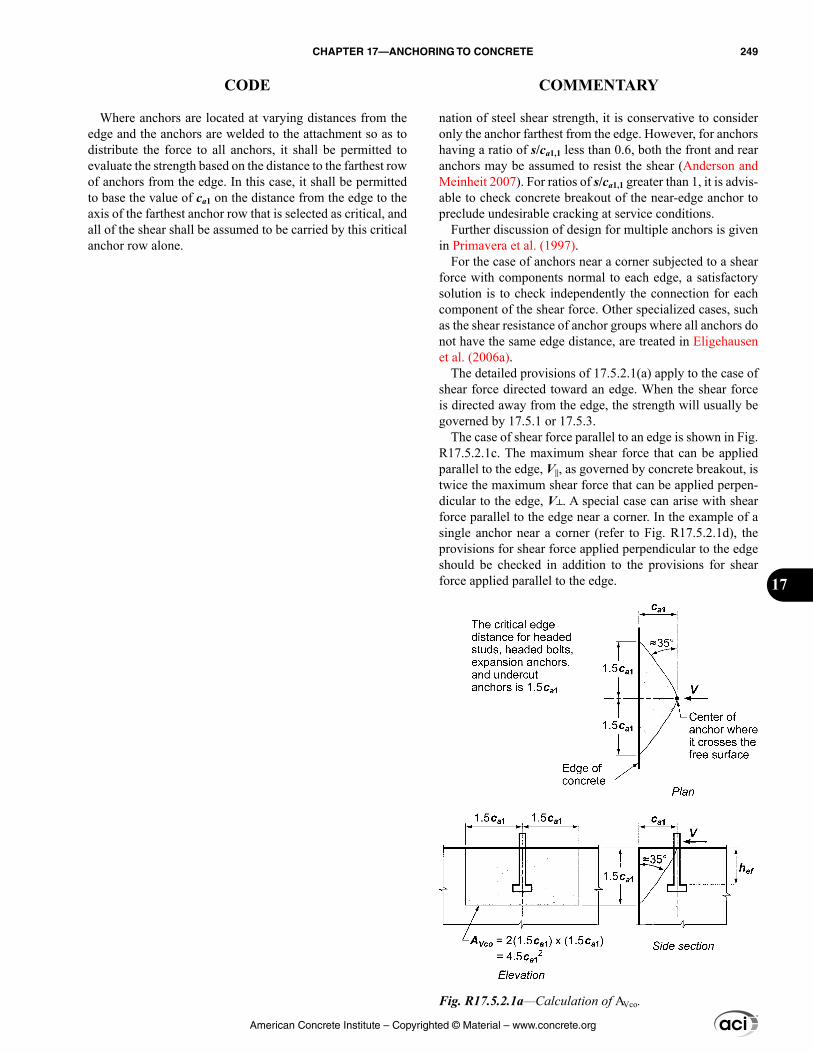
Where anchors are located at varying distances from the edge and the anchors are welded to the attachment so as to distribute the force to all anchors, it shall be permitted to evaluate the strength based on the distance to the farthest row of anchors from the edge. In this case, it shall be permitted to base the value of ca1 on the distance from the edge to the axis of the farthest anchor row that is selected as critical, and all of the shear shall be assumed to be carried by this critical anchor row alone.
nation of steel shear strength, it is conservative to consider only the anchor farthest from the edge. However, for anchors having a ratio of s/ca1,1 less than 0.6, both the front and rear anchors may be assumed to resist the shear (Anderson and Meinheit 2007). For ratios of s/ca1,1 greater than 1, it is advis-able to check concrete breakout of the near-edge anchor to preclude undesirable cracking at service conditions.
Further discussion of design for multiple anchors is given in Primavera et al. (1997).
For the case of anchors near a corner subjected to a shear force with components normal to each edge, a satisfactory solution is to check independently the connection for each component of the shear force. Other specialized cases, such as the shear resistance of anchor groups where all anchors do not have the same edge distance, are treated in Eligehausen et al. (2006a).
The detailed provisions of 17.5.2.1(a) apply to the case of shear force directed toward an edge. When the shear force is directed away from the edge, the strength will usually be governed by 17.5.1 or 17.5.3.
The case of shear force parallel to an edge is shown in Fig. R17.5.2.1c. The maximum shear force that can be applied parallel to the edge, V||, as governed by concrete breakout, is twice the maximum shear force that can be applied perpen-dicular to the edge, V. A special case can arise with shear force parallel to the edge near a corner. In the example of a single anchor near a corner (refer to Fig. R17.5.2.1d), the provisions for shear force applied perpendicular to the edge should be checked in addition to the provisions for shear force applied parallel to the edge.
Fig. R17.5.2.1a—Calculation of AVco.
American Concrete Institute – Copyrighted © Material – www.concrete.org
CHAPTER 17—ANCHORING TO CONCRETE 249
CODE COMMENTARY
17
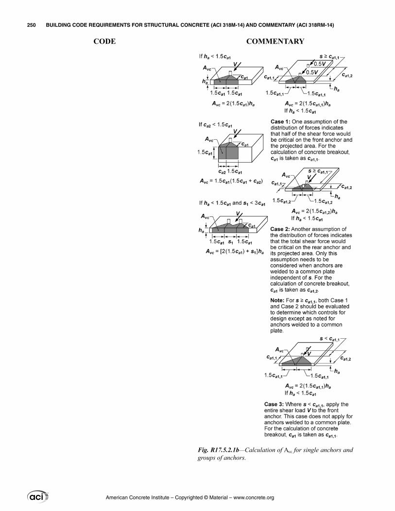
Fig. R17.5.2.1b—Calculation of Avc for single anchors and groups of anchors.
American Concrete Institute – Copyrighted © Material – www.concrete.org
250 BUILDING CODE REQUIREMENTS FOR STRUCTURAL CONCRETE (ACI 318M-14) AND COMMENTARY (ACI 318RM-14)
CODE COMMENTARY
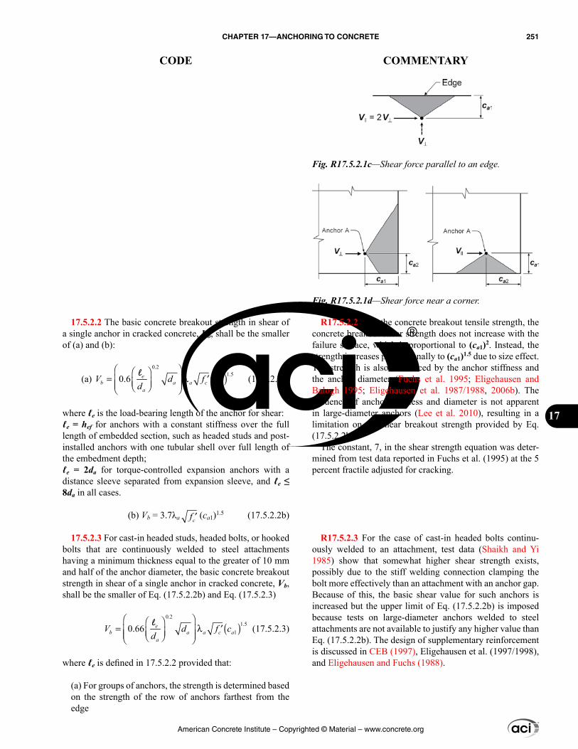
R17.5.2.2 Like the concrete breakout tensile strength, the concrete breakout shear strength does not increase with the failure surface, which is proportional to (ca1)2. Instead, the strength increases proportionally to (ca1)1.5 due to size effect. The strength is also influenced by the anchor stiffness and the anchor diameter (Fuchs et al. 1995; Eligehausen and Balogh 1995; Eligehausen et al. 1987/1988, 2006b). The influence of anchor stiffness and diameter is not apparent in large-diameter anchors (Lee et al. 2010), resulting in a limitation on the shear breakout strength provided by Eq. (17.5.2.2b).
The constant, 7, in the shear strength equation was deter-mined from test data reported in Fuchs et al. (1995) at the 5 percent fractile adjusted for cracking.
R17.5.2.3 For the case of cast-in headed bolts continu-ously welded to an attachment, test data (Shaikh and Yi 1985) show that somewhat higher shear strength exists, possibly due to the stiff welding connection clamping the bolt more effectively than an attachment with an anchor gap. Because of this, the basic shear value for such anchors is increased but the upper limit of Eq. (17.5.2.2b) is imposed because tests on large-diameter anchors welded to steel attachments are not available to justify any higher value than Eq. (17.5.2.2b). The design of supplementary reinforcement is discussed in CEB (1997), Eligehausen et al. (1997/1998), and Eligehausen and Fuchs (1988).
17.5.2.2 The basic concrete breakout strength in shear of a single anchor in cracked concrete, Vb, shall be the smaller of (a) and (b):
(a) ( )0.2
1.510.6
= λ ′
eb a a c a
a
V d f cdl
(17.5.2.2a)
where ℓe is the load-bearing length of the anchor for shear:ℓe = hef for anchors with a constant stiffness over the full length of embedded section, such as headed studs and post-installed anchors with one tubular shell over full length of the embedment depth;ℓe = 2da for torque-controlled expansion anchors with a distance sleeve separated from expansion sleeve, and ℓe ≤ 8da in all cases.
(b) Vb = 3.7λa ′cf (ca1)1.5 (17.5.2.2b)
17.5.2.3 For cast-in headed studs, headed bolts, or hooked bolts that are continuously welded to steel attachments having a minimum thickness equal to the greater of 10 mm and half of the anchor diameter, the basic concrete breakout strength in shear of a single anchor in cracked concrete, Vb, shall be the smaller of Eq. (17.5.2.2b) and Eq. (17.5.2.3)
( )0.2
1.510.66
= λ ′
eb a a c a
a
V d f cdl
(17.5.2.3)
where ℓe is defined in 17.5.2.2 provided that:
(a) For groups of anchors, the strength is determined based on the strength of the row of anchors farthest from the edge
Fig. R17.5.2.1c—Shear force parallel to an edge.
Fig. R17.5.2.1d—Shear force near a corner.
American Concrete Institute – Copyrighted © Material – www.concrete.org
CHAPTER 17—ANCHORING TO CONCRETE 251
CODE COMMENTARY
17
R17.5.2.4 For the case of anchors located in narrow sections of limited thickness where the edge distances perpendicular to the direction of load and the member thickness are less than 1.5ca1, the shear breakout strength calculated by the basic CCD Method (refer to R17.3.2) is overly conservative. These cases were studied for the Kappa Method (Eligehausen and Fuchs 1988) and the problem was pointed out by Lutz (1995). Similar to the approach used for concrete breakout strength in tension in 17.4.2.3, the concrete breakout strength in shear for this case is more accurately evaluated if the value of ca1 used in the equa-tions in 17.5.2.1 through 17.5.2.8 and in the calculation of AVc is limited to the maximum of two-thirds of the larger of the two edge distances perpendicular to the direction of shear, two-thirds of the member thickness, and one-third of the maximum spacing between anchors within the group, measured perpendicular to the direction of shear. The limit on ca1 of at least one-third of the maximum spacing between anchors within the group prevents the use of a calculated strength based on individual breakout prisms for a group anchor configuration.
This approach is illustrated in Fig. R17.5.2.4. In this example, the limiting value of ca1 is denoted as c′a1 and is used for the calculation of AVc, AVco, ψed,V, and ψh,V as well as for Vb (not shown). The requirement of 17.5.2.4 may be visualized by moving the actual concrete breakout surface originating at the actual ca1 toward the surface of the concrete in the direction of the applied shear load. The value of ca1 used for the calculation of AVc and in the equa-tions in 17.5.2.1 through 17.5.2.8 is determined when either: (a) an outer boundary of the failure surface first intersects the concrete surface; or (b) the intersection of the breakout surface between anchors within the group first intersects the concrete surface. For the example shown in Fig. R17.5.2.4, Point A shows the intersection of the assumed failure surface for limiting ca1 with the concrete surface.
(b) Anchor spacing s is not less than 65 mm(c) Reinforcement is provided at the corners if ca2 ≤ 1.5hef
17.5.2.4 Where anchors are located in narrow sections of limited thickness such that both edge distances ca2 and thickness ha are less than 1.5ca1, the value of ca1 used for the calculation of AVc in accordance with 17.5.2.1 as well as for the equations in 17.5.2.1 through 17.5.2.8 shall not exceed the largest of:
(a) ca2 /1.5, where ca2 is the largest edge distance(b) ha /1.5(c) s/3, where s is the maximum spacing perpendicular to direction of shear, between anchors within a group
American Concrete Institute – Copyrighted © Material – www.concrete.org
252 BUILDING CODE REQUIREMENTS FOR STRUCTURAL CONCRETE (ACI 318M-14) AND COMMENTARY (ACI 318RM-14)
CODE COMMENTARY
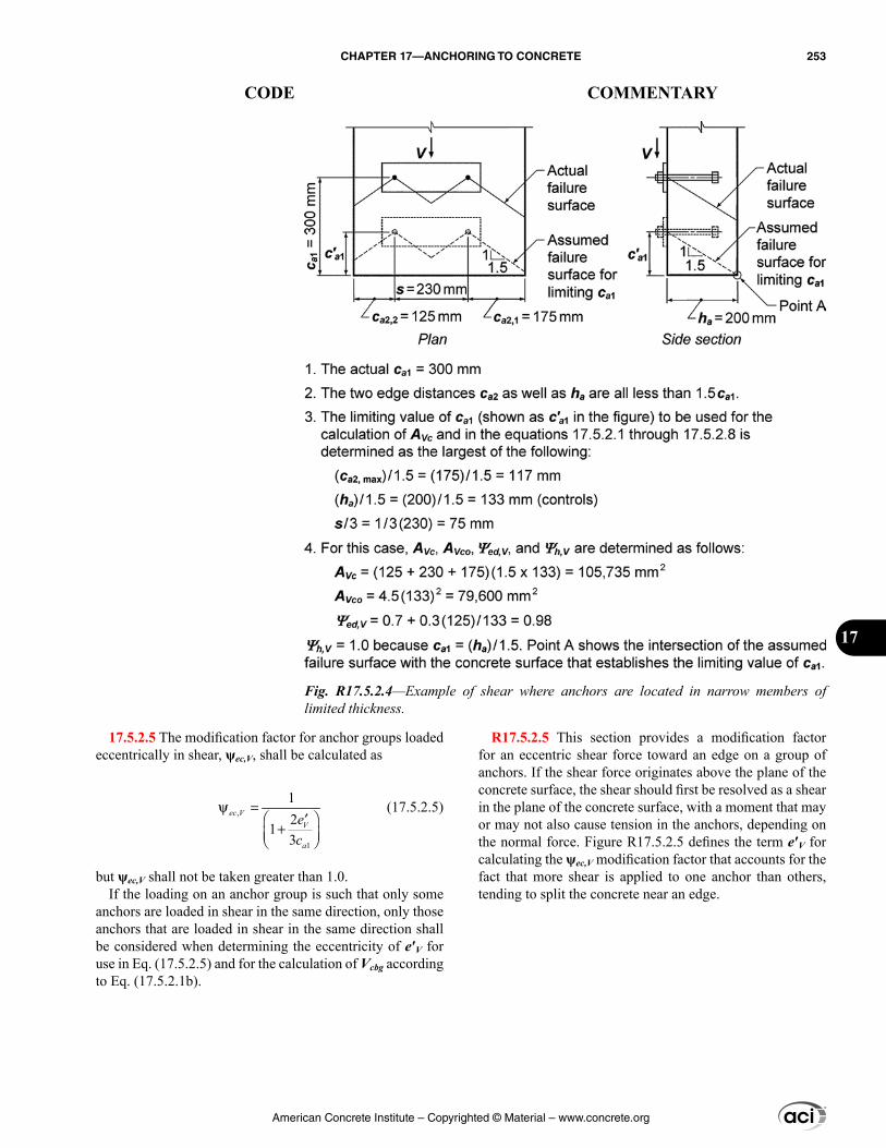
R17.5.2.5 This section provides a modification factor for an eccentric shear force toward an edge on a group of anchors. If the shear force originates above the plane of the concrete surface, the shear should first be resolved as a shear in the plane of the concrete surface, with a moment that may or may not also cause tension in the anchors, depending on the normal force. Figure R17.5.2.5 defines the term e′V for calculating the ψec,V modification factor that accounts for the fact that more shear is applied to one anchor than others, tending to split the concrete near an edge.
17.5.2.5 The modification factor for anchor groups loaded eccentrically in shear, ψec,V, shall be calculated as
,
1
12
13
ψ = ′+
ec VV
a
ec
(17.5.2.5)
but ψec,V shall not be taken greater than 1.0.If the loading on an anchor group is such that only some
anchors are loaded in shear in the same direction, only those anchors that are loaded in shear in the same direction shall be considered when determining the eccentricity of e′V for use in Eq. (17.5.2.5) and for the calculation of Vcbg according to Eq. (17.5.2.1b).
Fig. R17.5.2.4—Example of shear where anchors are located in narrow members of limited thickness.
American Concrete Institute – Copyrighted © Material – www.concrete.org
CHAPTER 17—ANCHORING TO CONCRETE 253
CODE COMMENTARY
17
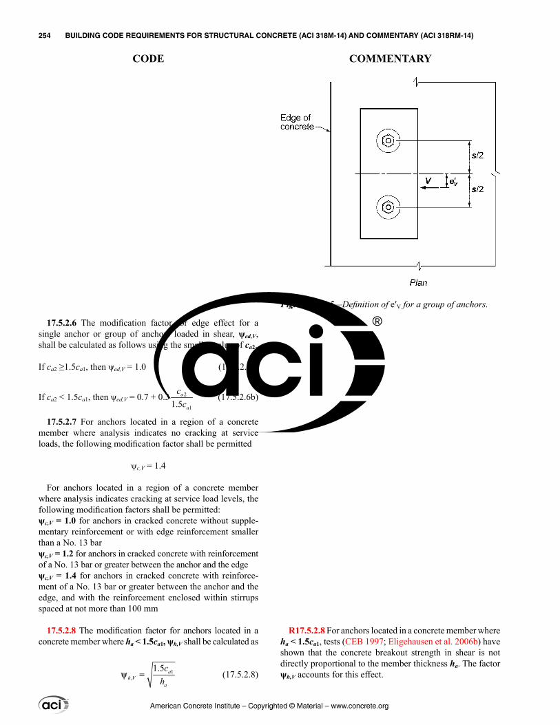
17.5.2.6 The modification factor for edge effect for a single anchor or group of anchors loaded in shear, ψed,V, shall be calculated as follows using the smaller value of ca2.
If ca2 ≥1.5ca1, then ψed,V = 1.0 (17.5.2.6a)
If ca2 < 1.5ca1, then ψed,V = 0.7 + 0.3 2
11.5a
a
cc
(17.5.2.6b)
17.5.2.7 For anchors located in a region of a concrete member where analysis indicates no cracking at service loads, the following modification factor shall be permitted
ψc,V = 1.4
For anchors located in a region of a concrete member where analysis indicates cracking at service load levels, the following modification factors shall be permitted:ψc,V = 1.0 for anchors in cracked concrete without supple-mentary reinforcement or with edge reinforcement smaller than a No. 13 barψc,V = 1.2 for anchors in cracked concrete with reinforcement of a No. 13 bar or greater between the anchor and the edgeψc,V = 1.4 for anchors in cracked concrete with reinforce-ment of a No. 13 bar or greater between the anchor and the edge, and with the reinforcement enclosed within stirrups spaced at not more than 100 mm
17.5.2.8 The modification factor for anchors located in a concrete member where ha < 1.5ca1, ψh,V shall be calculated as
1,
1.5ψ = a
h Va
ch
(17.5.2.8)
R17.5.2.8 For anchors located in a concrete member where ha < 1.5ca1, tests (CEB 1997; Eligehausen et al. 2006b) have shown that the concrete breakout strength in shear is not directly proportional to the member thickness ha. The factor ψh,V accounts for this effect.
Fig. R17.5.2.5—Definition of e′V for a group of anchors.
American Concrete Institute – Copyrighted © Material – www.concrete.org
254 BUILDING CODE REQUIREMENTS FOR STRUCTURAL CONCRETE (ACI 318M-14) AND COMMENTARY (ACI 318RM-14)
CODE COMMENTARY
but ψh,V shall not be taken less than 1.0.
17.5.2.9 Where anchor reinforcement is either developed in accordance with Chapter 25 on both sides of the breakout surface, or encloses the anchor and is developed beyond the breakout surface, the design strength of the anchor reinforcement shall be permitted to be used instead of the concrete breakout strength in determining ϕVn. A strength reduction factor of 0.75 shall be used in the design of the anchor reinforcement.
R17.5.2.9 For conditions where the factored shear force exceeds the concrete breakout strength of the anchor(s) in shear, or where the breakout strength is not evaluated, the nominal strength can be that of anchor reinforcement properly anchored, as shown in Fig. R17.5.2.9a and Fig. R17.5.2.9b. To ensure yielding of the anchor reinforcement, the enclosing anchor reinforcement in Fig. R17.5.2.9a should be in contact with the anchor and placed as close as practi-cable to the concrete surface. The research (Eligehausen et al. 2006b) on which the provisions for enclosing reinforce-ment (refer to Fig. R17.5.2.9a) are based was limited to anchor reinforcement with maximum diameter similar to a No. 16 bar. The larger bend radii associated with larger bar diameters may significantly reduce the effectiveness of the anchor reinforcement and, therefore, anchor reinforcement with a diameter larger than No. 19 is not recommended.
The reinforcement could also consist of stirrups and ties (as well as hairpins) enclosing the edge reinforcement embedded in the breakout cone and placed as close to the anchors as practicable (refer to Fig. R17.5.2.9b). Generally reinforcement spaced less than the lesser of 0.5ca1 and 0.3ca2 from the anchor centerline should be included as anchor reinforcement. In this case, the anchor reinforcement must be developed on both sides of the breakout surface. For equi-librium reasons, an edge reinforcement must be present. The research on which these provisions are based was limited to anchor reinforcement with maximum diameter similar to a No. 19 bar. Strut-and-tie models may also be used to design anchor reinforcement.
Because the anchor reinforcement is placed below where the shear is applied (refer to Fig. R17.5.2.9b), the force in the anchor reinforcement will be larger than the shear force. In sizing the anchor reinforcement, use of a 0.75 strength reduction factor ϕ is recommended as used for shear and for strut-and-tie models. As a practical matter, the use of anchor reinforcement is generally limited to cast-in anchors.
American Concrete Institute – Copyrighted © Material – www.concrete.org
CHAPTER 17—ANCHORING TO CONCRETE 255
CODE COMMENTARY
17
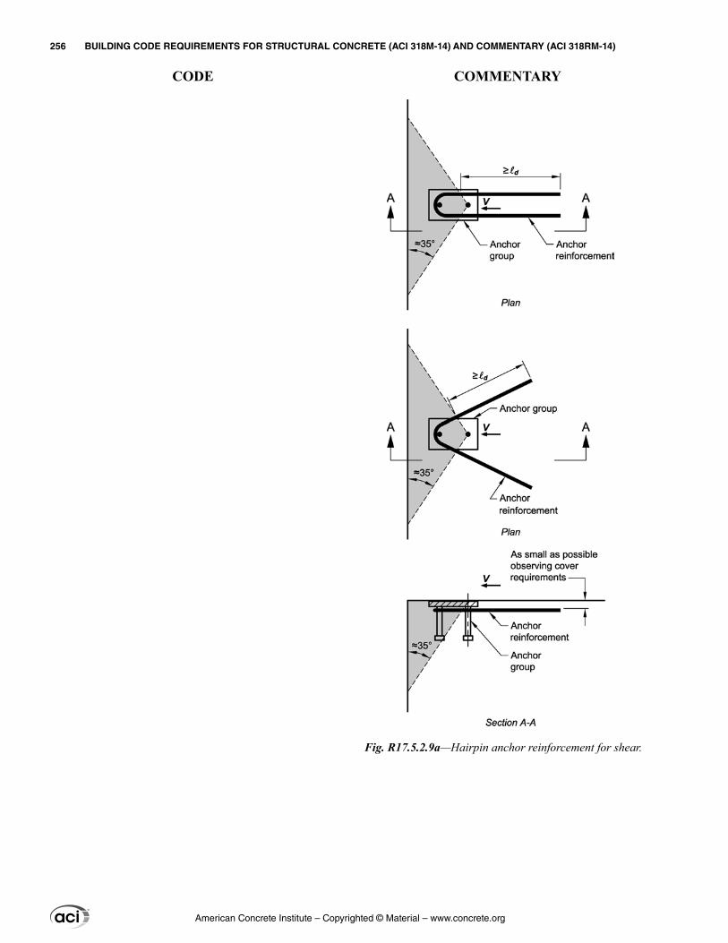
Fig. R17.5.2.9a—Hairpin anchor reinforcement for shear.
American Concrete Institute – Copyrighted © Material – www.concrete.org
256 BUILDING CODE REQUIREMENTS FOR STRUCTURAL CONCRETE (ACI 318M-14) AND COMMENTARY (ACI 318RM-14)
CODE COMMENTARY
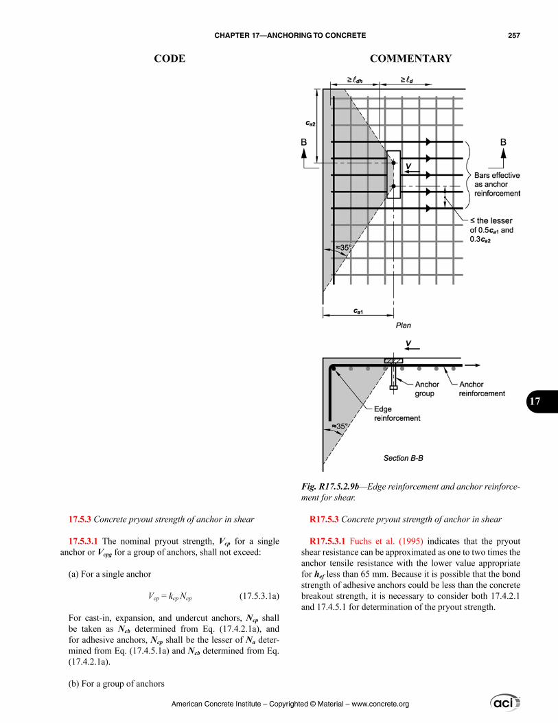
17.5.3 Concrete pryout strength of anchor in shear
17.5.3.1 The nominal pryout strength, Vcp for a single anchor or Vcpg for a group of anchors, shall not exceed:
(a) For a single anchor
Vcp = kcp Ncp (17.5.3.1a)
For cast-in, expansion, and undercut anchors, Ncp shall be taken as Ncb determined from Eq. (17.4.2.1a), and for adhesive anchors, Ncp shall be the lesser of Na deter-mined from Eq. (17.4.5.1a) and Ncb determined from Eq. (17.4.2.1a).
(b) For a group of anchors
R17.5.3 Concrete pryout strength of anchor in shear
R17.5.3.1 Fuchs et al. (1995) indicates that the pryout shear resistance can be approximated as one to two times the anchor tensile resistance with the lower value appropriate for hef less than 65 mm. Because it is possible that the bond strength of adhesive anchors could be less than the concrete breakout strength, it is necessary to consider both 17.4.2.1 and 17.4.5.1 for determination of the pryout strength.
Fig. R17.5.2.9b—Edge reinforcement and anchor reinforce-ment for shear.
American Concrete Institute – Copyrighted © Material – www.concrete.org
CHAPTER 17—ANCHORING TO CONCRETE 257
CODE COMMENTARY
17
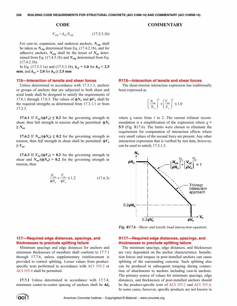
R17.6—Interaction of tensile and shear forces The shear-tension interaction expression has traditionally
been expressed as
1.0
ς ς
+ ≤ ua ua
n n
N VN V
where ς varies from 1 to 2. The current trilinear recom-mendation is a simplification of the expression where ς = 5/3 (Fig. R17.6). The limits were chosen to eliminate the requirement for computation of interaction effects where very small values of the second force are present. Any other interaction expression that is verified by test data, however, can be used to satisfy 17.3.1.3.
R17.7—Required edge distances, spacings, and thicknesses to preclude splitting failure
The minimum spacings, edge distances, and thicknesses are very dependent on the anchor characteristics. Installa-tion forces and torques in post-installed anchors can cause splitting of the surrounding concrete. Such splitting also can be produced in subsequent torquing during connec-tion of attachments to anchors including cast-in anchors. The primary source of values for minimum spacings, edge distances, and thicknesses of post-installed anchors should be the product-specific tests of ACI 355.2 and ACI 355.4. In some cases, however, specific products are not known in
Vcpg = kcp Ncpg (17.5.3.1b)
For cast-in, expansion, and undercut anchors, Ncpg shall be taken as Ncbg determined from Eq. (17.4.2.1b), and for adhesive anchors, Ncpg shall be the lesser of Nag deter-mined from Eq. (17.4.5.1b) and Ncbg determined from Eq. (17.4.2.1b).In Eq. (17.5.3.1a) and (17.5.3.1b), kcp = 1.0 for hef < 2.5
mm; and kcp = 2.0 for hef ≥ 2.5 mm
17.6—Interaction of tensile and shear forces Unless determined in accordance with 17.3.1.3, anchors
or groups of anchors that are subjected to both shear and axial loads shall be designed to satisfy the requirements of 17.6.1 through 17.6.3. The values of ϕNn and ϕVn shall be the required strengths as determined from 17.3.1.1 or from 17.2.3.
17.6.1 If Vua /(ϕVn) ≤ 0.2 for the governing strength in shear, then full strength in tension shall be permitted: ϕNn ≥ Nua.
17.6.2 If Nua/(ϕNn) ≤ 0.2 for the governing strength in tension, then full strength in shear shall be permitted: ϕVn ≥ Vua.
17.6.3 If Vua/(ϕVn) > 0.2 for the governing strength in shear and Nua /(ϕNn) > 0.2 for the governing strength in tension, then
1.2+ ≤φ φ
ua ua
n n
N VN V
(17.6.3)
17.7—Required edge distances, spacings, and thicknesses to preclude splitting failure
Minimum spacings and edge distances for anchors and minimum thicknesses of members shall conform to 17.7.1 through 17.7.6, unless supplementary reinforcement is provided to control splitting. Lesser values from product-specific tests performed in accordance with ACI 355.2 or ACI 355.4 shall be permitted.
17.7.1 Unless determined in accordance with 17.7.4, minimum center-to-center spacing of anchors shall be 4da
Fig. R17.6—Shear and tensile load interaction equation.
American Concrete Institute – Copyrighted © Material – www.concrete.org
258 BUILDING CODE REQUIREMENTS FOR STRUCTURAL CONCRETE (ACI 318M-14) AND COMMENTARY (ACI 318RM-14)
CODE COMMENTARY
for cast-in anchors that will not be torqued, and 6da for torqued cast-in anchors and post-installed anchors.
17.7.2 Unless determined in accordance with 17.7.4, minimum edge distances for cast-in anchors that will not be torqued shall be based on specified cover requirements for reinforcement in 20.6.1. For cast-in anchors that will be torqued, the minimum edge distances shall be 6da.
17.7.3 Unless determined in accordance with 17.7.4, minimum edge distances for post-installed anchors shall be based on the greater of specified cover requirements for rein-forcement in 20.6.1, or minimum edge distance requirements for the products as determined by tests in accordance with ACI 355.2 or ACI 355.4, and shall not be less than twice the maximum aggregate size. In the absence of product-specific ACI 355.2 or ACI 355.4 test information, the minimum edge distance shall not be less than:
Adhesive anchors ......................................................... 6daUndercut anchors .......................................................... 6daTorque-controlled anchors ............................................ 8daDisplacement-controlled anchors ............................... 10da
17.7.4 For anchors where installation does not produce a splitting force and that will not be torqued, if the edge distance or spacing is less than those specified in 17.7.1 to 17.7.3, calculations shall be performed by substituting for da a smaller value da′ that meets the requirements of 17.7.1 to 17.7.3. Calculated forces applied to the anchor shall be limited to the values corresponding to an anchor having a diameter of da′.
17.7.5 Unless determined from tests in accordance with ACI 355.2, the value of hef for an expansion or undercut post-installed anchor shall not exceed the greater of 2/3 of the member thickness, ha, and the member thickness minus 100 mm.
17.7.6 Unless determined from tension tests in accordance with ACI 355.2 or ACI 355.4, the critical edge distance cac shall not be taken less than:
Adhesive anchors ........................................................ 2hefUndercut anchors ...................................................... 2.5hefTorque-controlled expansion anchors ......................... 4hefDisplacement-controlled expansion anchors ............... 4hef
the design stage. Approximate values are provided for use in design.
R17.7.2 Because the edge cover over a deep embedment close to the edge can have a significant effect on the side-face blowout strength of 17.4.4, in addition to the normal concrete cover requirements, it may be advantageous to use larger cover to increase the side-face blowout strength.
R17.7.3 Drilling holes for post-installed anchors can cause microcracking. The requirement for a minimum edge distance twice the maximum aggregate size is to minimize the effects of such microcracking.
R17.7.4 In some cases, it may be desirable to use a larger-diameter anchor than the requirements on 17.7.1 to 17.7.3 permit. In these cases, it is permissible to use a larger-diam-eter anchor, provided the design strength of the anchor is based on a smaller assumed anchor diameter da′.
R17.7.5 Splitting failures are caused by the load transfer between the bolt and the concrete. The limitations on the value of hef do not apply to cast-in and adhesive anchors because the splitting forces associated with these anchor types are less than for expansion and undercut anchors.
For all post-installed anchors, the maximum embedment depth for a given member thickness should be limited as required to avoid back-face blowout on the opposite side of the concrete member during hole drilling and anchor setting. This is dependent on many variables, such as the anchor type, drilling method, drilling technique, type and size of drilling equipment, presence of reinforcement, and strength and condition of the concrete.
R17.7.6 The critical edge distance cac is determined by the corner test in ACI 355.2 or ACI 355.4, and is only applicable to designs for uncracked concrete. To permit the design of these types of anchors when product-specific information is not available, conservative default values for cac are provided. Research has indicated that the corner-test requirements are not met with ca,min = 1.5hef for many expan-sion anchors and some undercut anchors because installation of these types of anchors introduces splitting tensile stresses
American Concrete Institute – Copyrighted © Material – www.concrete.org
CHAPTER 17—ANCHORING TO CONCRETE 259
CODE COMMENTARY
17
in the concrete that are increased during load application, potentially resulting in a premature splitting failure. Simi-larly, adhesive anchors that meet the maximum embedment depth requirement of 17.7.5 may not fulfill the corner test requirements with ca,min = cNa due to the additional flexural stresses induced in the member by the anchor.
R17.8—Installation and inspection of anchors R17.8.1 Many anchor performance characteristics depend
on proper installation of the anchor. Installation of adhe-sive anchors should be performed by personnel qualified for the adhesive anchor system and installation procedures being used. Construction personnel can establish qualifica-tions by becoming certified through certification programs. For cast-in anchors, care must be taken that the anchors are securely positioned in the formwork and oriented in accor-dance with the construction documents. Furthermore, it should be ensured that the concrete around the anchors is properly consolidated. Inspection is particularly important for post-installed anchors to make certain that the manufac-turer’s recommended installation procedure, and in the case of adhesive anchors, printed installation instructions (MPII), are followed. For adhesive anchors, continuous monitoring of installations by qualified inspectors is recommended to ensure required installation procedures are followed. Post-installed anchor strength and deformation capacity are assessed by acceptance testing under ACI 355.2 or ACI 355.4. These tests are carried out assuming installation in accordance with the manufacturer’s recommended proce-dures (in the case of adhesive anchors, the MPII). Certain types of anchors can be sensitive to variations in hole diam-eter, cleaning conditions, orientation of the axis, magnitude of the installation torque, crack width, and other variables. Some of this sensitivity is indirectly accounted for in the assigned ϕ values for the different anchor categories, which depend in part on the results of the installation safety tests. Gross deviations from the ACI 355.2 or ACI 355.4 accep-tance testing results could occur if anchor components are altered, or if anchor installation criteria or procedures vary from those specified.
R17.8.2.1 Due to the sensitivity of bond strength to instal-lation, on-site quality control is important for adhesive anchors. Where appropriate, a proof loading program should be specified in the construction documents. For adhesive anchors, the construction documents must also provide all parameters relevant to the characteristic bond stress used in the design. These parameters may include, but are not limited to:
17.7.7 Construction documents shall specify use of anchors with a minimum edge distance as assumed in design.
17.8—Installation and inspection of anchors 17.8.1 Anchors shall be installed by qualified personnel
in accordance with the construction documents and, where applicable, manufacturer’s instructions. The construction documents shall require installation of post-installed adhe-sive anchors in accordance with the Manufacturer’s Printed Installation Instructions (MPII). Installation of adhesive anchors shall be performed by personnel trained to install adhesive anchors.
17.8.2 Installation of anchors shall be inspected in accor-dance with 1.9 and the general building code. Adhesive anchors shall be also subject to 17.8.2.1 through 17.8.2.4.
17.8.2.1 For adhesive anchors, the construction docu-ments shall specify proof loading where required in accor-dance with ACI 355.4. The construction documents shall also specify all parameters associated with the character-istic bond stress used for the design according to 17.4.5, including minimum age of concrete; concrete temperature range; moisture condition of concrete at time of installation;
American Concrete Institute – Copyrighted © Material – www.concrete.org
260 BUILDING CODE REQUIREMENTS FOR STRUCTURAL CONCRETE (ACI 318M-14) AND COMMENTARY (ACI 318RM-14)
CODE COMMENTARY
type of lightweight concrete, if applicable; and requirements for hole drilling and preparation.
17.8.2.2 Installation of adhesive anchors horizontally or upwardly inclined to support sustained tension loads shall be performed by personnel certified by an applicable certifica-tion program. Certification shall include written and perfor-mance tests in accordance with the ACI/CRSI Adhesive Anchor Installer Certification program, or equivalent.
17.8.2.3 The acceptability of certification other than the ACI/CRSI Adhesive Anchor Installer Certification shall be the responsibility of the licensed design professional.
17.8.2.4 Adhesive anchors installed in horizontal or upwardly inclined orientations to resist sustained tension loads shall be continuously inspected during installation by an inspector specially approved for that purpose by the building official. The special inspector shall furnish a report to the licensed design professional and building official that
(a) Acceptable anchor installation environment (dry or saturated concrete; concrete temperature range)(b) Acceptable drilling methods(c) Required hole cleaning procedures(d) Anchor type and size range (threaded rod or reinforcing bar)
Hole cleaning is intended to ensure that drilling debris and dust do not impair bond. Depending on the on-site condi-tions, hole cleaning may involve operations to remove drilling debris from the hole with vacuum or compressed air, mechanical brushing of the hole wall to remove surface dust, and a final step to evacuate any remaining dust or debris, usually with compressed air. Where wet core drilling is used, holes may be flushed with water and then dried with compressed air. If anchors are installed in locations where the concrete is saturated (for example, outdoor locations exposed to rainfall), the resulting drilling mud must be removed by other means. In all cases, the procedures used should be clearly described by the manufacturer in printed installation instructions accompanying the product. These printed installation instructions, which also describe the limits on concrete temperature and the presence of water during installation as well as the procedures necessary for void-free adhesive injection and adhesive cure requirements, constitute an integral part of the adhesive anchor system and are part of the assessment performed in accordance with ACI 355.4.
R17.8.2.2 The sensitivity of adhesive anchors to instal-lation orientation combined with sustained tension loading warrants installer certification. Certification may also be appropriate for other safety-related applications. Certifica-tion is established through an independent assessment such as the ACI/CRSI Adhesive Anchor Installation Certification Program, or similar program with equivalent requirements. In addition, installers should obtain instruction through product-specific training offered by manufacturers of quali-fied adhesive anchor systems.
R17.8.2.3 For the purposes of satisfying 17.8.2.3, an equivalent certified installer program should test the adhe-sive anchor installer’s knowledge and skill by an objec-tively fair and unbiased administration and grading of a written and performance exam. Programs should reflect the knowledge and skill required to install available commercial anchor systems. The effectiveness of a written exam should be verified through statistical analysis of the questions and answers. An equivalent program should provide a respon-sive and accurate mechanism to verify credentials, which are renewed on a periodic basis.
R17.8.2.4 The model code (2012 IBC) requires special inspection of all post-installed anchors. The installation of adhesive anchors in horizontal or upwardly inclined orienta-tions poses special challenges to the installer and requires particular attention to execution quality as well as an enhanced level of oversight. It is expected that these anchor
American Concrete Institute – Copyrighted © Material – www.concrete.org
CHAPTER 17—ANCHORING TO CONCRETE 261
CODE COMMENTARY
17

the work covered by the report has been performed and that the materials used and the installation procedures used conform with the approved construction documents and the Manufacturer’s Printed Installation Instructions (MPII).
installations will be inspected by a certified special inspector who is continuously present when and where the installa-tions are being performed.
American Concrete Institute – Copyrighted © Material – www.concrete.org
262 BUILDING CODE REQUIREMENTS FOR STRUCTURAL CONCRETE (ACI 318M-14) AND COMMENTARY (ACI 318RM-14)
CODE COMMENTARY
CHAPTER 18—EARTHQUAKE-RESISTANT STRUCTURES
18.1—Scope 18.1.1 This chapter shall apply to the design of nonpre-
stressed and prestressed concrete structures assigned to Seismic Design Categories (SDC) B through F, including, where applicable:
(a) Structural systems designated as part of the seismic-force-resisting system, including diaphragms, moment frames, structural walls, and foundations(b) Members not designated as part of the seismic-force-resisting system but required to support other loads while undergoing deformations associated with earthquake effects
18.1.2 Structures designed according to the provisions of this chapter are intended to resist earthquake motions through ductile inelastic response of selected members.
18.2—General 18.2.1 Structural systems
R18—EARTHQUAKE-RESISTANT STRUCTURES
R18.1—Scope Chapter 18 does not apply to structures assigned to
Seismic Design Category (SDC) A. For structures assigned to SDC B and C, Chapter 18 applies to structural systems designated as part of the seismic-force-resisting system. For structures assigned to SDC D through F, Chapter 18 applies to both structural systems designated as part of the seismic-force-resisting system and structural systems not designated as part of the seismic-force-resisting system.
Chapter 18 contains provisions considered to be the minimum requirements for a cast-in-place or precast concrete structure capable of sustaining a series of oscil-lations into the inelastic range of response without critical deterioration in strength. The integrity of the structure in the inelastic range of response should be maintained because the design earthquake forces defined in documents such as ASCE/SEI 7, the 2012 IBC, the UBC (ICBO 1997), and the NEHRP (FEMA P749) provisions are considered less than those corresponding to linear response at the antici-pated earthquake intensity (FEMA P749; Blume et al. 1961; Clough 1960; Gulkan and Sozen 1974).
The design philosophy in Chapter 18 is for cast-in-place concrete structures to respond in the nonlinear range when subjected to design-level ground motions, with decreased stiffness and increased energy dissipation but without crit-ical strength decay. Precast concrete structures designed in accordance with Chapter 18 are intended to emulate cast-in-place construction, except 18.5, 18.9.2.3, and 18.11.2.2, which permit precast construction with alternative yielding mechanisms. The combination of reduced stiffness and increased energy dissipation tends to reduce the response accelerations and lateral inertia forces relative to values that would occur were the structure to remain linearly elastic and lightly damped (Gulkan and Sozen 1974). Thus, the use of design forces representing earthquake effects such as those in ASCE/SEI 7 requires that the seismic-force-resisting system retain a substantial portion of its strength into the inelastic range under displacement reversals.
The provisions of Chapter 18 relate detailing require-ments to type of structural framing and SDC. Seismic design categories are adopted directly from ASCE/SEI 7, and relate to considerations of seismic hazard level, soil type, occu-pancy, and use. Before the 2008 Code, low, intermediate, and high seismic risk designations were used to delineate detailing requirements. For a qualitative comparison of seismic design categories and seismic risk designations, refer to Table R5.2.2. The assignment of a structure to a SDC is regulated by the general building code (refer to 4.4.6.1).
R18.2—General Structures assigned to SDC A need not satisfy require-
ments of Chapter 18 but must satisfy all other applicable requirements of this Code. Structures assigned to Seismic
American Concrete Institute – Copyrighted © Material – www.concrete.org
CHAPTER 18—EARTHQUAKE-RESISTANT STRUCTURES 263
CODE COMMENTARY
18
Design Categories B through F must satisfy requirements of Chapter 18 in addition to all other applicable requirements of this Code.
Sections 18.2.1.3 through 18.2.1.5 identify those parts of Chapter 18 that apply to the building based on its assigned SDC, regardless of the vertical elements of the seismic-force-resisting system. ASCE/SEI 7 defines the permissible vertical elements of the seismic-force-resisting system and applies where adopted. The remaining commentary of R18.2 summarizes the intent of ACI 318 regarding which vertical elements should be permissible in a building considering its SDC. Section 18.2.1.6 defines the requirements for the vertical elements of the seismic-force-resisting system.
The design and detailing requirements should be compat-ible with the level of inelastic response assumed in the calcu-lation of the design earthquake forces. The terms “ordinary”, “intermediate”, and “special” are used to facilitate this compatibility. For any given structural element or system, the terms “ordinary”, “intermediate”, and “special” refer to increasing requirements for detailing and proportioning, with expectations of increased deformation capacity. Struc-tures assigned to SDC B are not expected to be subjected to strong ground motion, but instead are expected to expe-rience low levels of ground motion at long time intervals. This Code provides some requirements for beam-column ordinary moment frames to improve deformation capacity.
Structures assigned to SDC C may be subjected to moder-ately strong ground motion. The designated seismic-force-resisting system typically comprises some combination of ordinary cast-in-place structural walls, intermediate precast structural walls, and intermediate moment frames. The general building code also may contain provisions for use of other seismic-force-resisting systems in SDC C. Provi-sion 18.2.1.6 defines requirements for whatever system is selected.
Structures assigned to SDC D, E, or F may be subjected to strong ground motion. It is the intent of ACI Committee 318 that the seismic-force-resisting system of structural concrete buildings assigned to SDC D, E, or F be provided by special moment frames, special structural walls, or a combination of the two. In addition to 18.2.2 through 18.2.8, these struc-tures also are required to satisfy requirements for continuous inspection (26.13.1.4), diaphragms and trusses (18.12), foun-dations (18.13), and gravity-load-resisting elements that are not designated as part of the seismic-force-resisting system (18.14). These provisions have been developed to provide the structure with adequate deformation capacity for the high demands expected for these seismic design categories.
The general building code may also permit the use of inter-mediate moment frames as part of dual systems for some buildings assigned to SDC D, E, or F. It is not the intent of ACI Committee 318 to recommend the use of interme-diate moment frames as part of moment-resisting frame or dual systems in SDC D, E, or F. The general building code may also permit substantiated alternative or nonprescriptive designs or, with various supplementary provisions, the use
18.2.1.1 All structures shall be assigned to a SDC in accor-dance with 4.4.6.1.
18.2.1.2 All members shall satisfy Chapters 1 to 17 and 19 to 26. Structures assigned to SDC B, C, D, E, or F also shall satisfy 18.2.1.3 through 18.2.1.7, as applicable. Where Chapter 18 conflicts with other chapters of this Code, Chapter 18 shall govern.
18.2.1.3 Structures assigned to SDC B shall satisfy 18.2.2.
18.2.1.4 Structures assigned to SDC C shall satisfy 18.2.2 and 18.2.3.
18.2.1.5 Structures assigned to SDC D, E, or F shall satisfy 18.2.2 through 18.2.8 and 18.12 through 18.14.
18.2.1.6 Structural systems designated as part of the seismic-force-resisting system shall be restricted to those designated by the general building code, or determined by other authority having jurisdiction in areas without a legally adopted building code. Except for SDC A, for which Chapter 18 does not apply, (a) through (h) shall be satisfied for each structural system designated as part of the seismic-force-resisting system, in addition to 18.2.1.3 through 18.2.1.5:
(a) Ordinary moment frames shall satisfy 18.3(b) Ordinary reinforced concrete structural walls need not satisfy any detailing provisions in Chapter 18, unless required by 18.2.1.3 or 18.2.1.4(c) Intermediate moment frames shall satisfy 18.4(d) Intermediate precast walls shall satisfy 18.5(e) Special moment frames shall satisfy 18.2.3 through 18.2.8 and 18.6 through 18.8(f) Special moment frames constructed using precast concrete shall satisfy 18.2.3 through 18.2.8 and 18.9(g) Special structural walls shall satisfy 18.2.3 through 18.2.8 and 18.10(h) Special structural walls constructed using precast concrete shall satisfy 18.2.3 through 18.2.8 and 18.11
18.2.1.7 A reinforced concrete structural system not satis-fying this chapter shall be permitted if it is demonstrated by experimental evidence and analysis that the proposed system will have strength and toughness equal to or exceeding those provided by a comparable reinforced concrete structure satisfying this chapter.
American Concrete Institute – Copyrighted © Material – www.concrete.org
264 BUILDING CODE REQUIREMENTS FOR STRUCTURAL CONCRETE (ACI 318M-14) AND COMMENTARY (ACI 318RM-14)
CODE COMMENTARY
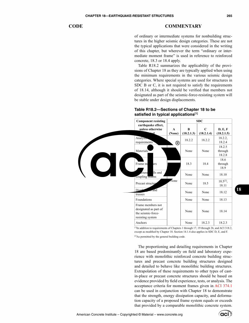
of ordinary or intermediate systems for nonbuilding struc-tures in the higher seismic design categories. These are not the typical applications that were considered in the writing of this chapter, but wherever the term “ordinary or inter-mediate moment frame” is used in reference to reinforced concrete, 18.3 or 18.4 apply.
Table R18.2 summarizes the applicability of the provi-sions of Chapter 18 as they are typically applied when using the minimum requirements in the various seismic design categories. Where special systems are used for structures in SDC B or C, it is not required to satisfy the requirements of 18.14, although it should be verified that members not designated as part of the seismic-force-resisting system will be stable under design displacements.
Table R18.2—Sections of Chapter 18 to be satisfied in typical applications[1]
Component resisting earthquake effect, unless otherwise
noted
SDC
A(None)
B(18.2.1.3)
C(18.2.1.4)
D, E, F(18.2.1.5)
Analysis and design requirements
None
18.2.2 18.2.2 18.2.2, 18.2.4
Materials None None18.2.5
through 18.2.8
Frame members 18.3 18.418.6
through 18.9
Structural walls and coupling beams None None 18.10
Precast structural walls None 18.5 18.5[2], 18.11
Diaphragms and trusses None None 18.12
Foundations None None 18.13
Frame members not designated as part of the seismic-force-resisting system
None None 18.14
Anchors None 18.2.3 18.2.3[1]In addition to requirements of Chapters 1 through 17, 19 through 26, and ACI 318.2, except as modified by Chapter 18. Section 14.1.4 also applies in SDC D, E, and F.[2]As permitted by the general building code.
The proportioning and detailing requirements in Chapter 18 are based predominantly on field and laboratory expe-rience with monolithic reinforced concrete building struc-tures and precast concrete building structures designed and detailed to behave like monolithic building structures. Extrapolation of these requirements to other types of cast-in-place or precast concrete structures should be based on evidence provided by field experience, tests, or analysis. The acceptance criteria for moment frames given in ACI 374.1 can be used in conjunction with Chapter 18 to demonstrate that the strength, energy dissipation capacity, and deforma-tion capacity of a proposed frame system equals or exceeds that provided by a comparable monolithic concrete system.
American Concrete Institute – Copyrighted © Material – www.concrete.org
CHAPTER 18—EARTHQUAKE-RESISTANT STRUCTURES 265
CODE COMMENTARY
18
ACI ITG-5.1 provides similar information for precast wall systems.
The toughness requirement in 18.2.1.7 refers to the requirement to maintain structural integrity of the entire seismic-force-resisting system at lateral displacements anticipated for the maximum considered earthquake motion. Depending on the energy-dissipation characteristics of the structural system used, such displacements may be larger than for a monolithic reinforced concrete structure satisfying the prescriptive provisions of other parts of this Code.
R18.2.2 Analysis and proportioning of structural members—It is assumed that the distribution of required strength to the various components of a seismic-force-resisting system will be determined from the analysis of a linearly elastic model of the system acted upon by the factored forces, as required by the general building code. If nonlinear response history analyses are to be used, base motions should be selected after a detailed study of the site conditions and local seismic history.
Because the basis for earthquake-resistant design admits nonlinear response, it is necessary to investigate the stability of the seismic-force-resisting system, as well as its interac-tion with other structural and nonstructural members, under expected lateral displacements corresponding to maximum considered earthquake ground motion. For lateral displace-ment calculations, assuming all the structural members to be fully cracked is likely to lead to better estimates of the possible drift than using uncracked stiffness for all members. The analysis assumptions described in 6.6.3.1.2 and 6.6.3.1.3 may be used to estimate lateral deflections of reinforced concrete building systems.
The main objective of Chapter 18 is the safety of the struc-ture. The intent of 18.2.2.1 and 18.2.2.2 is to draw atten-tion to the influence of nonstructural members on structural response and to hazards from falling objects.
Section 18.2.2.3 serves as an alert that the base of struc-ture as defined in analysis may not necessarily correspond to the foundation or ground level. Details of columns and walls extending below the base of structure to the founda-tion are required to be consistent with those above the base of structure.
In selecting member sizes for earthquake-resistant struc-tures, it is important to consider constructibility problems related to congestion of reinforcement. The design should be such that all reinforcement can be assembled and placed in the proper location and that concrete can be cast and consolidated properly. Using the upper limits of permitted reinforcement ratios may lead to construction problems.
18.2.2 Analysis and proportioning of structural members
18.2.2.1 The interaction of all structural and nonstructural members that affect the linear and nonlinear response of the structure to earthquake motions shall be considered in the analysis.
18.2.2.2 Rigid members assumed not to be a part of the seismic-force-resisting system shall be permitted provided their effect on the response of the system is considered in the structural design. Consequences of failure of structural and nonstructural members that are not a part of the seismic-force-resisting system shall be considered.
18.2.2.3 Structural members extending below the base of structure that are required to transmit forces resulting from earthquake effects to the foundation shall comply with the requirements of Chapter 18 that are consistent with the seismic-force-resisting system above the base of structure.
18.2.3 Anchoring to concrete
18.2.3.1 Anchors resisting earthquake-induced forces in structures assigned to SDC C, D, E, or F shall be in accor-dance with 17.2.3.
American Concrete Institute – Copyrighted © Material – www.concrete.org
266 BUILDING CODE REQUIREMENTS FOR STRUCTURAL CONCRETE (ACI 318M-14) AND COMMENTARY (ACI 318RM-14)
CODE COMMENTARY
R18.2.4 Strength reduction factors
R18.2.4.1 Chapter 21 contains strength reduction factors for all members, joints, and connections of earthquake-resis-tant structures, including specific provisions in 21.2.4 for buildings that use special moment frames, special structural walls, and intermediate precast walls.
R18.2.5 Concrete in special moment frames and special structural walls—Requirements of this section refer to concrete quality in frames and walls that resist earthquake-induced forces. The maximum specified compressive strength of lightweight concrete to be used in structural design calcu-lations is limited to 35 MPa, primarily because of paucity of experimental and field data on the behavior of members made with lightweight concrete subjected to displacement reversals in the nonlinear range. If convincing evidence is developed for a specific application, the limit on maximum specified compressive strength of lightweight concrete may be increased to a level justified by the evidence.
R18.2.6 Reinforcement in special moment frames and special structural walls—Use of longitudinal reinforce-ment with strength substantially higher than that assumed in design will lead to higher shear and bond stresses at the time of development of yield moments. These conditions may lead to brittle failures in shear or bond and should be avoided even if such failures may occur at higher loads than those anticipated in design. Therefore, an upper limit is placed on the actual yield strength of the steel (refer to 20.2.2.5). ASTM A706M for low-alloy steel reinforcing bars includes both Grade 420 and Grade 550; however, only Grade 420 is generally permitted because of insufficient data to confirm applicability of existing code provisions for structures using the higher grade. Section 18.2.1.7 permits alternative mate-rial such as ASTM A706M Grade 550 if results of tests and analytical studies are presented in support of its use.
The requirement for a tensile strength greater than the yield strength of the reinforcement (20.2.2.5) is based on the assumption that the capability of a structural member to develop inelastic rotation capacity is a function of the length of the yield region along the axis of the member. In inter-preting experimental results, the length of the yield region has been related to the relative magnitudes of nominal and yield moments (ACI 352R). According to this interpretation, the greater the ratio of nominal to yield moment, the longer the yield region. Chapter 20 requires that the ratio of actual tensile strength to actual yield strength be at least 1.25.
The restrictions on the values of fy and fyt apply to all types of transverse reinforcement, including spirals, circular hoops, rectilinear hoops, and crossties. The restrictions on the values of fy and fyt in 20.2.2.4 for calculating nominal shear strength are intended to limit the width of shear cracks. Research results (Budek et al. 2002; Muguruma and Wata-nabe 1990; Sugano et al. 1990) indicate that higher yield
18.2.4 Strength reduction factors
18.2.4.1 Strength reduction factors shall be in accordance with Chapter 21.
18.2.5 Concrete in special moment frames and special structural walls
18.2.5.1 Specified compressive strength of concrete in special moment frames and special structural walls shall be in accordance with the special seismic systems requirements of Table 19.2.1.1.
18.2.6 Reinforcement in special moment frames and special structural walls
18.2.6.1 Reinforcement in special moment frames and special structural walls shall be in accordance with the special seismic systems requirements of 20.2.2.
American Concrete Institute – Copyrighted © Material – www.concrete.org
CHAPTER 18—EARTHQUAKE-RESISTANT STRUCTURES 267
CODE COMMENTARY
18
18.2.7 Mechanical splices in special moment frames and special structural walls
18.2.7.1 Mechanical splices shall be classified as (a) or (b):
(a) Type 1 – Mechanical splice conforming to 25.5.7(b) Type 2 – Mechanical splice conforming to 25.5.7 and capable of developing the specified tensile strength of the spliced bars
18.2.7.2 Type 1 mechanical splices shall not be located within a distance equal to twice the member depth from the column or beam face for special moment frames or from critical sections where yielding of the reinforcement is likely to occur as a result of lateral displacements beyond the linear range of behavior. Type 2 mechanical splices shall be permitted at any location, except as noted in 18.9.2.1(c).
18.2.8 Welded splices in special moment frames and special structural walls
18.2.8.1 Welded splices in reinforcement resisting earth-quake-induced forces shall conform to 25.5.7 and shall not be located within a distance equal to twice the member depth from the column or beam face for special moment frames or
strengths can be used effectively as confinement reinforce-ment as specified in 18.7.5.4.
R18.2.7 Mechanical splices in special moment frames and special structural walls—In a structure undergoing inelastic deformations during an earthquake, the tensile stresses in reinforcement may approach the tensile strength of the rein-forcement. The requirements for Type 2 mechanical splices are intended to avoid a splice failure when the reinforcement is subjected to expected stress levels in yielding regions. Type 1 mechanical splices are not required to satisfy the more stringent requirements for Type 2 mechanical splices, and may not be capable of resisting the stress levels expected in yielding regions. The locations of Type 1 mechanical splices are restricted because tensile stresses in reinforcement in yielding regions can exceed the strength requirements of 25.5.7. The restriction on Type 1 mechanical splices applies to all reinforcement resisting earthquake effects, including transverse reinforcement.
Recommended detailing practice would preclude the use of splices in regions of potential yielding in members resisting earthquake effects. If use of mechanical splices in regions of potential yielding cannot be avoided, there should be documentation on the actual strength characteristics of the bars to be spliced, on the force-deformation character-istics of the spliced bar, and on the ability of the Type 2 mechanical splice to be used to meet the specified perfor-mance requirements.
Although mechanical splices as defined by 18.2.7 need not be staggered, staggering is encouraged and may be necessary for constructibility or provide enough space around the splice for installation or to meet the clear spacing requirements.
R18.2.7.1 The additional requirement for a Type 2 mechan-ical splice is intended to result in a mechanical splice capable of sustaining inelastic strains through multiple cycles.
R18.2.8 Welded splices in special moment frames and special structural walls
R18.2.8.1 Welding of reinforcement should be in accor-dance with AWS D1.4 as required in Chapter 26. The loca-tions of welded splices are restricted because reinforcement tension stresses in yielding regions can exceed the strength
American Concrete Institute – Copyrighted © Material – www.concrete.org
268 BUILDING CODE REQUIREMENTS FOR STRUCTURAL CONCRETE (ACI 318M-14) AND COMMENTARY (ACI 318RM-14)
CODE COMMENTARY
from critical sections where yielding of the reinforcement is likely to occur as a result of lateral displacements beyond the linear range of behavior.
18.2.8.2 Welding of stirrups, ties, inserts, or other similar elements to longitudinal reinforcement required by design shall not be permitted.
18.3—Ordinary moment frames 18.3.1 Scope
18.3.1.1 This section shall apply to ordinary moment frames forming part of the seismic-force-resisting system.
18.3.2 Beams shall have at least two continuous bars at both top and bottom faces. Continuous bottom bars shall have area not less than one-fourth the maximum area of bottom bars along the span. These bars shall be anchored to develop fy in tension at the face of support.
18.3.3 Columns having unsupported length ℓu ≤ 5c1 shall have ϕVn at least the lesser of (a) and (b):
(a) The shear associated with development of nominal moment strengths of the column at each restrained end of the unsupported length due to reverse curvature bending. Column flexural strength shall be calculated for the factored axial force, consistent with the direction of the lateral forces considered, resulting in the highest flexural strength.(b) The maximum shear obtained from design load combi-nations that include E, with ΩoE substituted for E.
18.4—Intermediate moment frames 18.4.1 Scope
18.4.1.1 This section shall apply to intermediate moment frames including two-way slabs without beams forming part of the seismic-force-resisting system.
18.4.2 Beams
18.4.2.1 Beams shall have at least two continuous bars at both top and bottom faces. Continuous bottom bars shall have area not less than one-fourth the maximum area of bottom bars along the span. These bars shall be anchored to develop fy in tension at the face of support.
18.4.2.2 The positive moment strength at the face of the joint shall be at least one-third the negative moment strength provided at that face of the joint. Neither the negative nor the
requirements of 25.5.7. The restriction on welded splices applies to all reinforcement resisting earthquake effects, including transverse reinforcement.
R18.2.8.2 Welding of crossing reinforcing bars can lead to local embrittlement of the steel. If welding of crossing bars is used to facilitate fabrication or placement of rein-forcement, it should be done only on bars added for such purposes. The prohibition of welding crossing reinforcing bars does not apply to bars that are welded with welding operations under continuous, competent control, as in the manufacture of welded-wire reinforcement.
R18.3—Ordinary moment frames This section applies only to ordinary moment frames
assigned to SDC B. The provisions for beam reinforcement are intended to improve continuity in the framing members and thereby improve lateral force resistance and structural integrity; these provisions do not apply to slab-column moment frames. The provisions for columns are intended to provide additional capacity to resist shear for columns with proportions that would otherwise make them more suscep-tible to shear failure under earthquake loading.
R18.4—Intermediate moment frames The objective of the requirements in 18.4.2.3 and 18.4.3.1
is to reduce the risk of failure in shear in beams and columns during an earthquake. Two options are provided to deter-mine the factored shear force.
R18.4.2 Beams—According to 18.4.2.3(a), the factored shear force is determined from a free-body diagram obtained by cutting through the beam ends, with end moments assumed equal to the nominal moment strengths acting in reverse curvature bending, both clockwise and counter-clockwise. Figure R18.4.2 demonstrates only one of the two options that are to be considered for every beam. To determine the maximum beam shear, it is assumed that its nominal moment strengths (ϕ = 1.0 for moment) are devel-oped simultaneously at both ends of its clear span. As indi-cated in Fig. R18.4.2, the shear associated with this condi-
American Concrete Institute – Copyrighted © Material – www.concrete.org
CHAPTER 18—EARTHQUAKE-RESISTANT STRUCTURES 269
CODE COMMENTARY
18
positive moment strength at any section along the length of the beam shall be less than one-fifth the maximum moment strength provided at the face of either joint.
18.4.2.3 ϕVn shall be at least the lesser of (a) and (b):
(a) The sum of the shear associated with development of nominal moment strengths of the beam at each restrained end of the clear span due to reverse curvature bending and the shear calculated for factored gravity loads(b) The maximum shear obtained from design load combinations that include E, with E taken as twice that prescribed by the general building code
18.4.2.4 At both ends of the beam, hoops shall be provided over a length of at least 2h measured from the face of the supporting member toward midspan. The first hoop shall be located not more than 50 mm from the face of the supporting member. Spacing of hoops shall not exceed the smallest of (a) through (d):
(a) d/4(b) Eight times the diameter of the smallest longitudinal bar enclosed(c) 24 times the diameter of the hoop bar(d) 300 mm
18.4.2.5 Transverse reinforcement spacing shall not exceed d/2 throughout the length of the beam.
18.4.2.6 In beams having factored axial compressive force exceeding Agfc′/10, transverse reinforcement required by 18.4.2.5 shall conform to 25.7.2.2 and either 25.7.2.3 or 25.7.2.4.
tion [(Mnℓ + Mnr)/ℓn] is added algebraically to the shear due to the factored gravity loads to obtain the design shear for the beam. For the example shown, both the dead load wD and the live load wL have been assumed to be uniformly distributed. Effects of E acting vertically are to be included if required by the general building code.
Provision 18.4.2.3(b) bases Vu on the load combination including the earthquake effect E, which should be doubled. For example, the load combination defined by Eq. (5.3.1.e) would be
U = 1.2D + 2.0E + 1.0L + 0.2S
where E is the value specified by the general building code. The factor of 1.0 applied to L is allowed to be reduced to 0.5 in accordance with 5.3.3.
Transverse reinforcement at the ends of the beam is required to be hoops. In most cases, transverse reinforce-ment required by 18.4.2.3 for the design shear force will be more than those required by 18.4.2.4.
Beams may be subjected to axial compressive force due to prestressing or applied loads. The additional requirements in 18.4.2.6 are intended to provide lateral support for beam longitudinal reinforcement.
American Concrete Institute – Copyrighted © Material – www.concrete.org
270 BUILDING CODE REQUIREMENTS FOR STRUCTURAL CONCRETE (ACI 318M-14) AND COMMENTARY (ACI 318RM-14)
CODE COMMENTARY
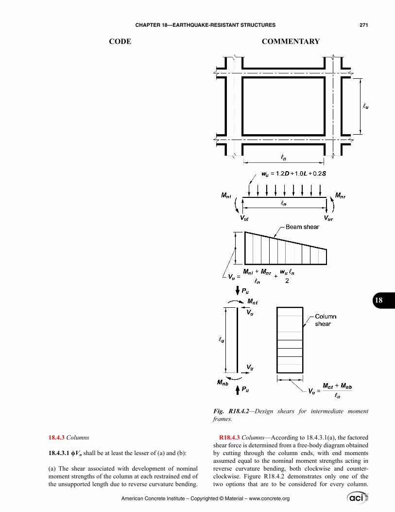
18.4.3 Columns
18.4.3.1 ϕVn shall be at least the lesser of (a) and (b):
(a) The shear associated with development of nominal moment strengths of the column at each restrained end of the unsupported length due to reverse curvature bending.
R18.4.3 Columns—According to 18.4.3.1(a), the factored shear force is determined from a free-body diagram obtained by cutting through the column ends, with end moments assumed equal to the nominal moment strengths acting in reverse curvature bending, both clockwise and counter-clockwise. Figure R18.4.2 demonstrates only one of the two options that are to be considered for every column.
Fig. R18.4.2—Design shears for intermediate moment frames.
American Concrete Institute – Copyrighted © Material – www.concrete.org
CHAPTER 18—EARTHQUAKE-RESISTANT STRUCTURES 271
CODE COMMENTARY
18
Column flexural strength shall be calculated for the factored axial force, consistent with the direction of the lateral forces considered, resulting in the highest flexural strength(b) The maximum shear obtained from factored load combinations that include E, with ΩoE substituted for E
18.4.3.2 Columns shall be spirally reinforced in accor-dance with Chapter 10 or shall be in accordance with 18.4.3.3 through 18.4.3.5. Provision 18.4.3.6 shall apply to all columns supporting discontinuous stiff members.
18.4.3.3 At both ends of the column, hoops shall be provided at spacing so over a length ℓo measured from the joint face. Spacing so shall not exceed the smallest of (a) through (d):
(a) 8 times the diameter of the smallest longitudinal bar enclosed(b) 24 times the diameter of the hoop bar(c) One-half of the smallest cross-sectional dimension of the column(d) 300 mm
Length ℓo shall not be less than the greatest of (e), (f), and (g):
(e) One-sixth of the clear span of the column(f) Maximum cross-sectional dimension of the column(g) 450 mm
18.4.3.4 The first hoop shall be located not more than so/2 from the joint face.
18.4.3.5 Outside of length ℓo, spacing of transverse rein-forcement shall be in accordance with 10.7.6.5.2.
18.4.3.6 Columns supporting reactions from discontin-uous stiff members, such as walls, shall be provided with transverse reinforcement at the spacing so in accordance with 18.4.3.3 over the full height beneath the level at which the discontinuity occurs if the portion of factored axial compres-sive force in these members related to earthquake effects exceeds Agfc′/10. If design forces have been magnified to account for the overstrength of the vertical elements of the seismic-force-resisting system, the limit of Agfc′/10 shall be increased to Agfc′/4. Transverse reinforcement shall extend above and below the column in accordance with 18.7.5.6(b).
18.4.4 Joints
18.4.4.1 Beam-column joints shall have transverse rein-forcement conforming to Chapter 15.
18.4.5 Two-way slabs without beams
The factored axial force Pu should be chosen to develop the largest moment strength of the column within the range of design axial forces. Provision 18.4.3.1(b) for columns is similar to 18.4.2.3(b) for beams except it bases Vu on load combinations including the earthquake effect E, with E increased by the overstrength factor Ωo rather than the factor 2.0. In ASCE/SEI 7, Ωo = 3.0 for intermediate moment frames. The higher factor for columns relative to beams is because of greater concerns about shear failures in columns.
Transverse reinforcement at the ends of columns is required to be spirals or hoops. The amount of transverse reinforcement at the ends must satisfy both 18.4.3.1 and 18.4.3.2. Note that hoops require seismic hooks at both ends.
Discontinuous structural walls and other stiff members can impose large axial forces on supporting columns during earthquakes. The required transverse reinforcement in 18.4.3.6 is to improve column toughness under anticipated demands. The factored axial compressive force related to earthquake effect should include the factor Ωo if required by the general building code.
R18.4.5 Two-way slabs without beams—Section 18.4.5 applies to two-way slabs without beams, such as flat plates.
American Concrete Institute – Copyrighted © Material – www.concrete.org
272 BUILDING CODE REQUIREMENTS FOR STRUCTURAL CONCRETE (ACI 318M-14) AND COMMENTARY (ACI 318RM-14)
CODE COMMENTARY
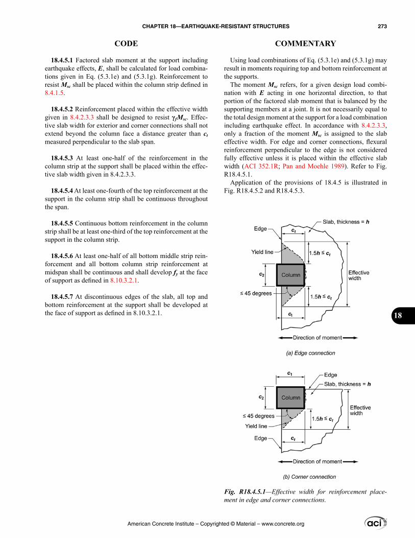
Using load combinations of Eq. (5.3.1e) and (5.3.1g) may result in moments requiring top and bottom reinforcement at the supports.
The moment Msc refers, for a given design load combi-nation with E acting in one horizontal direction, to that portion of the factored slab moment that is balanced by the supporting members at a joint. It is not necessarily equal to the total design moment at the support for a load combination including earthquake effect. In accordance with 8.4.2.3.3, only a fraction of the moment Msc is assigned to the slab effective width. For edge and corner connections, flexural reinforcement perpendicular to the edge is not considered fully effective unless it is placed within the effective slab width (ACI 352.1R; Pan and Moehle 1989). Refer to Fig. R18.4.5.1.
Application of the provisions of 18.4.5 is illustrated in Fig. R18.4.5.2 and R18.4.5.3.
18.4.5.1 Factored slab moment at the support including earthquake effects, E, shall be calculated for load combina-tions given in Eq. (5.3.1e) and (5.3.1g). Reinforcement to resist Msc shall be placed within the column strip defined in 8.4.1.5.
18.4.5.2 Reinforcement placed within the effective width given in 8.4.2.3.3 shall be designed to resist γfMsc. Effec-tive slab width for exterior and corner connections shall not extend beyond the column face a distance greater than ct measured perpendicular to the slab span.
18.4.5.3 At least one-half of the reinforcement in the column strip at the support shall be placed within the effec-tive slab width given in 8.4.2.3.3.
18.4.5.4 At least one-fourth of the top reinforcement at the support in the column strip shall be continuous throughout the span.
18.4.5.5 Continuous bottom reinforcement in the column strip shall be at least one-third of the top reinforcement at the support in the column strip.
18.4.5.6 At least one-half of all bottom middle strip rein-forcement and all bottom column strip reinforcement at midspan shall be continuous and shall develop fy at the face of support as defined in 8.10.3.2.1.
18.4.5.7 At discontinuous edges of the slab, all top and bottom reinforcement at the support shall be developed at the face of support as defined in 8.10.3.2.1.
Fig. R18.4.5.1—Effective width for reinforcement place-ment in edge and corner connections.
American Concrete Institute – Copyrighted © Material – www.concrete.org
CHAPTER 18—EARTHQUAKE-RESISTANT STRUCTURES 273
CODE COMMENTARY
18
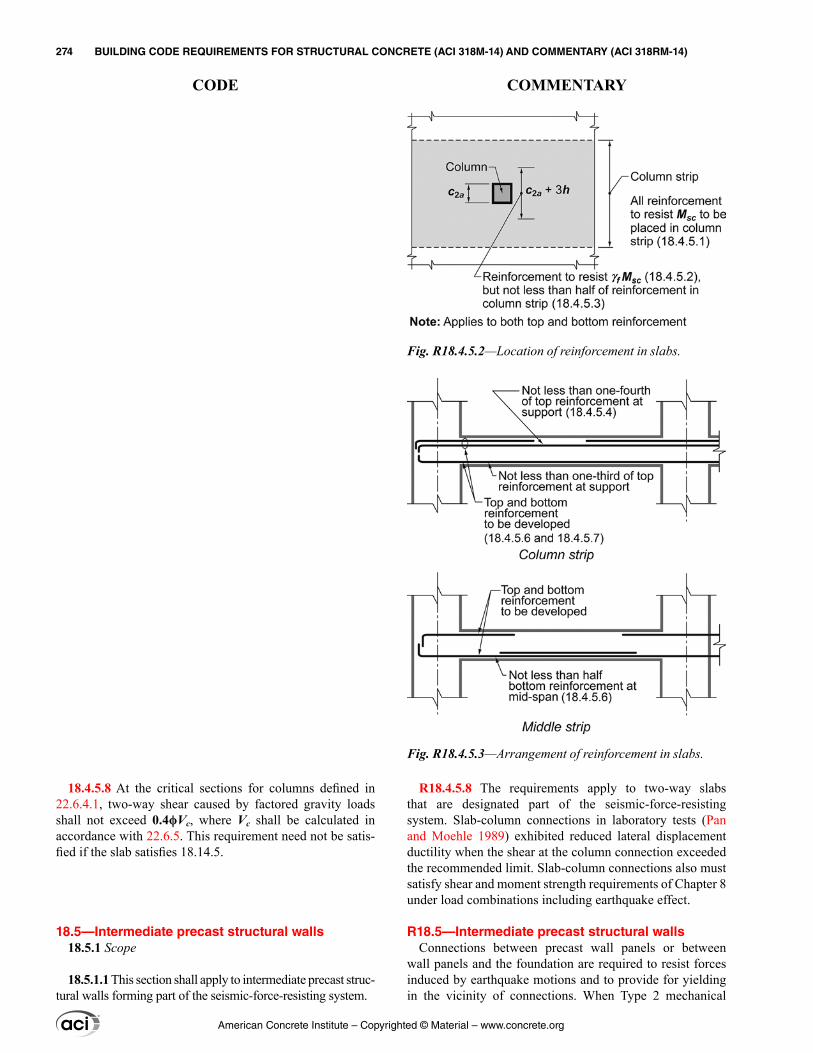
R18.4.5.8 The requirements apply to two-way slabs that are designated part of the seismic-force-resisting system. Slab-column connections in laboratory tests (Pan and Moehle 1989) exhibited reduced lateral displacement ductility when the shear at the column connection exceeded the recommended limit. Slab-column connections also must satisfy shear and moment strength requirements of Chapter 8 under load combinations including earthquake effect.
R18.5—Intermediate precast structural walls Connections between precast wall panels or between
wall panels and the foundation are required to resist forces induced by earthquake motions and to provide for yielding in the vicinity of connections. When Type 2 mechanical
18.4.5.8 At the critical sections for columns defined in 22.6.4.1, two-way shear caused by factored gravity loads shall not exceed 0.4ϕVc, where Vc shall be calculated in accordance with 22.6.5. This requirement need not be satis-fied if the slab satisfies 18.14.5.
18.5—Intermediate precast structural walls 18.5.1 Scope
18.5.1.1 This section shall apply to intermediate precast struc-tural walls forming part of the seismic-force-resisting system.
Fig. R18.4.5.2—Location of reinforcement in slabs.
Fig. R18.4.5.3—Arrangement of reinforcement in slabs.
American Concrete Institute – Copyrighted © Material – www.concrete.org
274 BUILDING CODE REQUIREMENTS FOR STRUCTURAL CONCRETE (ACI 318M-14) AND COMMENTARY (ACI 318RM-14)
CODE COMMENTARY
splices are used to directly connect primary reinforcement, the probable strength of the splice should be at least 1.5 times the specified yield strength of the reinforcement.
R18.6—Beams of special moment frames R18.6.1 Scope—This section applies to beams of special
moment frames resisting lateral loads induced by earthquake motions. In previous Codes, any frame member subjected to a factored axial compressive force exceeding (Agfc′/10) under any load combination was to be proportioned and detailed as described in 18.7. In the 2014 Code, all require-ments for beams are contained in 18.6 regardless of the magnitude of axial compressive force.
This Code is written with the assumption that special moment frames comprise horizontal beams and vertical columns interconnected by beam-column joints. It is accept-able for beams and columns to be inclined provided the resulting system behaves as a frame—that is, lateral resis-tance is provided primarily by moment transfer between beams and columns rather than by strut or brace action. In special moment frames, it is acceptable to design beams to resist combined moment and axial force as occurs in beams that act both as moment frame members and as chords or collectors of a diaphragm. It is acceptable for beams of special moment frames to cantilever beyond columns, but such cantilevers are not part of the special moment frame that forms part of the seismic-force-resisting system. It is acceptable for beams of a special moment frame to connect into a wall boundary if the boundary is reinforced as a special moment frame column in accordance with 18.7. A concrete braced frame, in which lateral resistance is provided primarily by axial forces in beams and columns, is not a recognized seismic-force-resisting system.
R18.6.2 Dimensional limits—Experimental evidence (Hirosawa 1977) indicates that, under reversals of displace-ment into the nonlinear range, behavior of continuous members having length-to-depth ratios of less than 4 is significantly different from the behavior of relatively slender members. Design rules derived from experience with rela-tively slender members do not apply directly to members with length-to-depth ratios less than 4, especially with respect to shear strength.
Geometric constraints indicated in 18.6.2.1(b) and (c) were derived from practice and research (ACI 352R) on rein-forced concrete frames resisting earthquake-induced forces. The limits in 18.6.2.1(c) define the maximum beam width
18.5.2 General
18.5.2.1 In connections between wall panels, or between wall panels and the foundation, yielding shall be restricted to steel elements or reinforcement.
18.5.2.2 For elements of the connection that are not designed to yield, the required strength shall be based on 1.5Sy of the yielding portion of the connection.
18.5.2.3 In structures assigned to SDC D, E, or F, wall piers shall be designed in accordance with 18.10.8 or 18.14.
18.6—Beams of special moment frames 18.6.1 Scope
18.6.1.1 This section shall apply to beams of special moment frames that form part of the seismic-force-resisting system and are proportioned primarily to resist flexure and shear.
18.6.1.2 Beams of special moment frames shall frame into columns of special moment frames satisfying 18.7.
18.6.2 Dimensional limits
18.6.2.1 Beams shall satisfy (a) through (c):
(a) Clear span ℓn shall be at least 4d(b) Width bw shall be at least the lesser of 0.3h and 250 mm(c) Projection of the beam width beyond the width of the supporting column on each side shall not exceed the lesser of c2 and 0.75c1.
American Concrete Institute – Copyrighted © Material – www.concrete.org
CHAPTER 18—EARTHQUAKE-RESISTANT STRUCTURES 275
CODE COMMENTARY
18
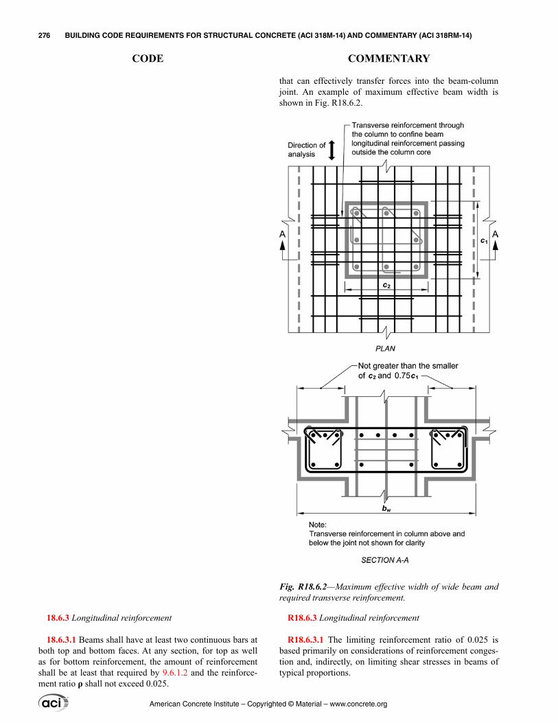
that can effectively transfer forces into the beam-column joint. An example of maximum effective beam width is shown in Fig. R18.6.2.
R18.6.3 Longitudinal reinforcement
R18.6.3.1 The limiting reinforcement ratio of 0.025 is based primarily on considerations of reinforcement conges-tion and, indirectly, on limiting shear stresses in beams of typical proportions.
18.6.3 Longitudinal reinforcement
18.6.3.1 Beams shall have at least two continuous bars at both top and bottom faces. At any section, for top as well as for bottom reinforcement, the amount of reinforcement shall be at least that required by 9.6.1.2 and the reinforce-ment ratio ρ shall not exceed 0.025.
Fig. R18.6.2—Maximum effective width of wide beam and required transverse reinforcement.
American Concrete Institute – Copyrighted © Material – www.concrete.org
276 BUILDING CODE REQUIREMENTS FOR STRUCTURAL CONCRETE (ACI 318M-14) AND COMMENTARY (ACI 318RM-14)
CODE COMMENTARY
R18.6.3.3 Lap splices of reinforcement are prohibited along lengths where flexural yielding is anticipated because such splices are not reliable under conditions of cyclic loading into the inelastic range. Transverse reinforcement for lap splices at any location is mandatory because of the potential of concrete cover spalling and the need to confine the splice.
R18.6.3.5 These provisions were developed, in part, based on observations of building performance in earthquakes (ACI 423.3R). For calculating the average prestress, the least cross-sectional dimension in a beam normally is the web dimension, and is not intended to refer to the flange thickness. In a potential plastic hinge region, the limitation on strain and the requirement for unbonded tendons are intended to prevent fracture of tendons under inelastic earth-quake deformation. Calculation of strain in the prestressing steel is required considering the anticipated inelastic mecha-nism of the structure. For prestressing steel unbonded along the full beam span, strains generally will be well below the specified limit. For prestressing steel with short unbonded length through or adjacent to the joint, the additional strain due to earthquake deformation is calculated as the product of the depth to the neutral axis and the sum of plastic hinge rotations at the joint, divided by the unbonded length.
The restrictions on the flexural strength provided by the tendons are based on the results of analytical and experi-mental studies (Ishizuka and Hawkins 1987; Park and Thompson 1977). Although satisfactory seismic perfor-mance can be obtained with greater amounts of prestressing steel, this restriction is needed to allow the use of the same response modification and deflection amplification factors as those specified in model codes for special moment frames without prestressing steel. Prestressed special moment frames will generally contain continuous prestressing steel that is anchored with adequate cover at or beyond the exte-rior face of each beam-column connection located at the ends of the moment frame.
18.6.3.2 Positive moment strength at joint face shall be at least one-half the negative moment strength provided at that face of the joint. Both the negative and the positive moment strength at any section along member length shall be at least one-fourth the maximum moment strength provided at face of either joint.
18.6.3.3 Lap splices of deformed longitudinal reinforce-ment shall be permitted if hoop or spiral reinforcement is provided over the lap length. Spacing of the transverse rein-forcement enclosing the lap-spliced bars shall not exceed the lesser of d/4 and 100 mm. Lap splices shall not be used in locations (a) through (c):
(a) Within the joints(b) Within a distance of twice the beam depth from the face of the joint(c) Within a distance of twice the beam depth from crit-ical sections where flexural yielding is likely to occur as a result of lateral displacements beyond the elastic range of behavior
18.6.3.4 Mechanical splices shall conform to 18.2.7 and welded splices shall conform to 18.2.8.
18.6.3.5 Unless used in a special moment frame as permitted by 18.9.2.3, prestressing shall satisfy (a) through (d):
(a) The average prestress fpc calculated for an area equal to the least cross-sectional dimension of the beam multiplied by the perpendicular cross-sectional dimension shall not exceed the lesser of 3.5 MPa and fc′/10.(b) Prestressing steel shall be unbonded in potential plastic hinge regions, and the calculated strains in prestressing steel under the design displacement shall be less than 0.01.(c) Prestressing steel shall not contribute more than one-fourth of the positive or negative flexural strength at the critical section in a plastic hinge region and shall be anchored at or beyond the exterior face of the joint.(d) Anchorages of post-tensioning tendons resisting earth-quake-induced forces shall be capable of allowing tendons to withstand 50 cycles of loading, with prestressed rein-forcement forces bounded by 40 and 85 percent of the specified tensile strength of the prestressing steel.
American Concrete Institute – Copyrighted © Material – www.concrete.org
CHAPTER 18—EARTHQUAKE-RESISTANT STRUCTURES 277
CODE COMMENTARY
18
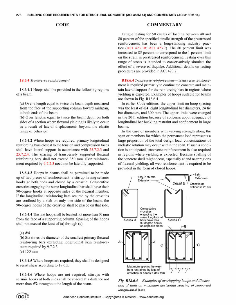
Fatigue testing for 50 cycles of loading between 40 and 80 percent of the specified tensile strength of the prestressed reinforcement has been a long-standing industry prac-tice (ACI 423.3R; ACI 423.7). The 80 percent limit was increased to 85 percent to correspond to the 1 percent limit on the strain in prestressed reinforcement. Testing over this range of stress is intended to conservatively simulate the effect of a severe earthquake. Additional details on testing procedures are provided in ACI 423.7.
R18.6.4 Transverse reinforcement—Transverse reinforce-ment is required primarily to confine the concrete and main-tain lateral support for the reinforcing bars in regions where yielding is expected. Examples of hoops suitable for beams are shown in Fig. R18.6.4.
In earlier Code editions, the upper limit on hoop spacing was the least of d/4, eight longitudinal bar diameters, 24 tie bar diameters, and 300 mm. The upper limits were changed in the 2011 edition because of concerns about adequacy of longitudinal bar buckling restraint and confinement in large beams.
In the case of members with varying strength along the span or members for which the permanent load represents a large proportion of the total design load, concentrations of inelastic rotation may occur within the span. If such a condi-tion is anticipated, transverse reinforcement is also required in regions where yielding is expected. Because spalling of the concrete shell might occur, especially at and near regions of flexural yielding, all web reinforcement is required to be provided in the form of closed hoops.
18.6.4 Transverse reinforcement
18.6.4.1 Hoops shall be provided in the following regions of a beam:
(a) Over a length equal to twice the beam depth measured from the face of the supporting column toward midspan, at both ends of the beam(b) Over lengths equal to twice the beam depth on both sides of a section where flexural yielding is likely to occur as a result of lateral displacements beyond the elastic range of behavior.
18.6.4.2 Where hoops are required, primary longitudinal reinforcing bars closest to the tension and compression faces shall have lateral support in accordance with 25.7.2.3 and 25.7.2.4. The spacing of transversely supported flexural reinforcing bars shall not exceed 350 mm. Skin reinforce-ment required by 9.7.2.3 need not be laterally supported.
18.6.4.3 Hoops in beams shall be permitted to be made up of two pieces of reinforcement: a stirrup having seismic hooks at both ends and closed by a crosstie. Consecutive crossties engaging the same longitudinal bar shall have their 90-degree hooks at opposite sides of the flexural member. If the longitudinal reinforcing bars secured by the crossties are confined by a slab on only one side of the beam, the 90-degree hooks of the crossties shall be placed on that side.
18.6.4.4 The first hoop shall be located not more than 50 mm from the face of a supporting column. Spacing of the hoops shall not exceed the least of (a) through (c):
(a) d/4(b) Six times the diameter of the smallest primary flexural reinforcing bars excluding longitudinal skin reinforce-ment required by 9.7.2.3(c) 150 mm
18.6.4.5 Where hoops are required, they shall be designed to resist shear according to 18.6.5.
18.6.4.6 Where hoops are not required, stirrups with seismic hooks at both ends shall be spaced at a distance not more than d/2 throughout the length of the beam.
Fig. R18.6.4— Examples of overlapping hoops and illustra-tion of limit on maximum horizontal spacing of supported longitudinal bars.
American Concrete Institute – Copyrighted © Material – www.concrete.org
278 BUILDING CODE REQUIREMENTS FOR STRUCTURAL CONCRETE (ACI 318M-14) AND COMMENTARY (ACI 318RM-14)
CODE COMMENTARY
R18.6.5 Shear strength—Unless a beam possesses a moment strength that is on the order of 3 or 4 times the design moment, it should be assumed that it will yield in flexure in the event of a major earthquake. The design shear force should be selected so as to be a good approximation of the maximum shear that may develop in a member. Therefore, required shear strength for frame members is related to flex-ural strengths of the designed member rather than to factored shear forces indicated by lateral load analysis. The condi-tions described by 18.6.5.1 are illustrated in Fig. R18.6.5.
Because the actual yield strength of the longitudinal reinforcement may exceed the specified yield strength and because strain hardening of the reinforcement is likely to take place at a joint subjected to large rotations, required shear strengths are determined using a stress of at least 1.25fy in the longitudinal reinforcement.
Experimental studies (Popov et al. 1972) of reinforced concrete members subjected to cyclic loading have demon-strated that more shear reinforcement is required to ensure a flexural failure if the member is subjected to alternating nonlinear displacements than if the member is loaded in only one direction: the necessary increase of shear reinforcement being higher in the case of no axial load. This observation is reflected in the Code (refer to 18.6.5.2) by eliminating the term representing the contribution of concrete to shear strength. The added conservatism on shear is deemed neces-sary in locations where potential flexural hinging may occur. However, this stratagem, chosen for its relative simplicity, should not be interpreted to mean that no concrete is required to resist shear. On the contrary, it may be argued that the concrete core resists all the shear with the shear (transverse) reinforcement confining and strengthening the concrete. The confined concrete core plays an important role in the behavior of the beam and should not be reduced to a minimum just because the design expression does not explicitly recognize it.
18.6.4.7 In beams having factored axial compressive force exceeding Agfc′/10, hoops satisfying 18.7.5.2 through 18.7.5.4 shall be provided along lengths given in 18.6.4.1. Along the remaining length, hoops satisfying 18.7.5.2 shall have spacing s not exceeding the lesser of six times the diameter of the smallest longitudinal beam bars and 150 mm. Where concrete cover over transverse reinforce-ment exceeds 100 mm, additional transverse reinforcement having cover not exceeding 100 mm and spacing not exceeding 300 mm shall be provided.
18.6.5 Shear strength
18.6.5.1 Design forces—The design shear force Ve shall be calculated from consideration of the forces on the portion of the beam between faces of the joints. It shall be assumed that moments of opposite sign corresponding to probable flex-ural strength, Mpr, act at the joint faces and that the beam is loaded with the factored tributary gravity load along its span.
18.6.5.2 Transverse reinforcement—Transverse reinforce-ment over the lengths identified in 18.6.4.1 shall be designed to resist shear assuming Vc = 0 when both (a) and (b) occur:
(a) The earthquake-induced shear force calculated in accordance with 18.6.5.1 represents at least one-half of the maximum required shear strength within those lengths.(b) The factored axial compressive force Pu including earthquake effects is less than Agfc′/20.
American Concrete Institute – Copyrighted © Material – www.concrete.org
CHAPTER 18—EARTHQUAKE-RESISTANT STRUCTURES 279
CODE COMMENTARY
18
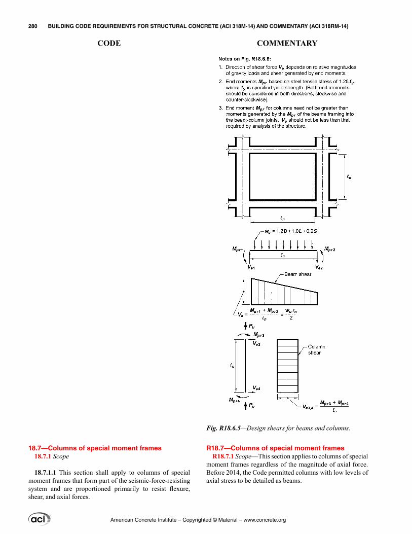
R18.7—Columns of special moment frames R18.7.1 Scope—This section applies to columns of special
moment frames regardless of the magnitude of axial force. Before 2014, the Code permitted columns with low levels of axial stress to be detailed as beams.
18.7—Columns of special moment frames 18.7.1 Scope
18.7.1.1 This section shall apply to columns of special moment frames that form part of the seismic-force-resisting system and are proportioned primarily to resist flexure, shear, and axial forces.
Fig. R18.6.5—Design shears for beams and columns.
American Concrete Institute – Copyrighted © Material – www.concrete.org
280 BUILDING CODE REQUIREMENTS FOR STRUCTURAL CONCRETE (ACI 318M-14) AND COMMENTARY (ACI 318RM-14)
CODE COMMENTARY
R18.7.2 Dimensional limits—The geometric constraints in this provision follow from previous practice (Seismology Committee of SEAOC 1996).
R18.7.3 Minimum flexural strength of columns—The intent of 18.7.3.2 is to reduce the likelihood of yielding in columns that are considered as part of the seismic-force-resisting system. If columns are not stronger than beams framing into a joint, there is increased likelihood of inelastic action. In the worst case of weak columns, flexural yielding can occur at both ends of all columns in a given story, resulting in a column failure mechanism that can lead to collapse.
In 18.7.3.2, the nominal strengths of the beams and columns are calculated at the joint faces, and those strengths are compared directly using Eq. (18.7.3.2). The 1995 and earlier Codes required design strengths to be compared at the center of the joint, which typically produced similar results but with added calculation effort.
In determining the nominal moment strength of a beam section in negative bending (top in tension), longitudinal reinforcement contained within an effective flange width of a top slab that acts monolithically with the beam increases the beam strength. French and Moehle (1991), on beam-column subassemblies under lateral loading, indicates that using the effective flange widths defined in 6.3.2 gives reasonable estimates of beam negative moment strengths of interior connections at story displacements approaching 2 percent of story height. This effective width is conservative where the slab terminates in a weak spandrel.
If 18.7.3.2 cannot be satisfied at a joint, 18.7.3.3 requires that any positive contribution of the column or columns involved to the lateral strength and stiffness of the structure is to be ignored. Negative contributions of the column or columns should not be ignored. For example, ignoring the stiffness of the columns ought not to be used as a justifica-tion for reducing the design base shear. If inclusion of those columns in the analytical model of the building results in an increase in torsional effects, the increase should be consid-ered as required by the general building code. Furthermore, the column must be provided with transverse reinforcement to increase its resistance to shear and axial forces.
R18.7.4 Longitudinal reinforcement—The lower limit of the area of longitudinal reinforcement is to control time-dependent deformations and to have the yield moment exceed the cracking moment. The upper limit of the area reflects concern for reinforcement congestion, load transfer from floor elements to column (especially in low-rise construction) and the development of high shear stresses.
18.7.2 Dimensional limits
18.7.2.1 Columns shall satisfy (a) and (b):
(a) The shortest cross-sectional dimension, measured on a straight line passing through the geometric centroid, shall be at least 300 mm(b) The ratio of the shortest cross-sectional dimension to the perpendicular dimension shall be at least 0.4.
18.7.3 Minimum flexural strength of columns
18.7.3.1 Columns shall satisfy 18.7.3.2 or 18.7.3.3.
18.7.3.2 The flexural strengths of the columns shall satisfy
∑Mnc ≥ (6/5)∑Mnb (18.7.3.2)
where∑Mnc is sum of nominal flexural strengths of columns framing into the joint, evaluated at the faces of the joint. Column flexural strength shall be calculated for the factored axial force, consistent with the direction of the lateral forces considered, resulting in the lowest flexural strength.∑Mnb is sum of nominal flexural strengths of the beams framing into the joint, evaluated at the faces of the joint. In T-beam construction, where the slab is in tension under moments at the face of the joint, slab reinforcement within an effective slab width defined in accordance with 6.3.2 shall be assumed to contribute to Mnb if the slab reinforcement is developed at the critical section for flexure.
Flexural strengths shall be summed such that the column moments oppose the beam moments. Equation (18.7.3.2) shall be satisfied for beam moments acting in both directions in the vertical plane of the frame considered.
18.7.3.3 If 18.7.3.2 is not satisfied at a joint, the lateral strength and stiffness of the columns framing into that joint shall be ignored when calculating strength and stiffness of the structure. These columns shall conform to 18.14.
18.7.4 Longitudinal reinforcement
18.7.4.1 Area of longitudinal reinforcement, Ast, shall be at least 0.01Ag and shall not exceed 0.06Ag.
18.7.4.2 In columns with circular hoops, there shall be at least six longitudinal bars.
American Concrete Institute – Copyrighted © Material – www.concrete.org
CHAPTER 18—EARTHQUAKE-RESISTANT STRUCTURES 281
CODE COMMENTARY
18
Spalling of the shell concrete, which is likely to occur near the ends of the column in frames of typical configura-tion, makes lap splices in these locations vulnerable. If lap splices are to be used at all, they should be located near the midheight where stress reversal is likely to be limited to a smaller stress range than at locations near the joints. Trans-verse reinforcement is required along the lap-splice length because of the uncertainty in moment distributions along the height and the need for confinement of lap splices subjected to stress reversals (Sivakumar et al. 1983).
R18.7.5 Transverse reinforcement—This section is concerned with confining the concrete and providing lateral support to the longitudinal reinforcement.
R18.7.5.1 This section stipulates a minimum length over which to provide closely-spaced transverse reinforcement at the column ends, where flexural yielding normally occurs. Research results indicate that the length should be increased by 50 percent or more in locations, such as the base of a building, where axial loads and flexural demands may be especially high (Watson et al. 1994).
R18.7.5.2 Sections 18.7.5.2 and 18.7.5.3 provide require-ments for configuration of transverse reinforcement for columns and joints of special moment frames. Figure R18.7.5.2 shows an example of transverse reinforcement provided by one hoop and three crossties. Crossties with a 90-degree hook are not as effective as either crossties with 135-degree hooks or hoops in providing confinement. For lower values of Pu/Agfc′ and lower concrete compres-sive strengths, crossties with 90-degree hooks are adequate if the ends are alternated along the length and around the perimeter of the column. For higher values of Pu/Agfc′, for which compression-controlled behavior is expected, and for higher compressive strengths, for which behavior tends to be more brittle, the improved confinement provided by having corners of hoops or seismic hooks supporting all longitu-dinal bars is important to achieving intended performance. Where these conditions apply, crossties with seismic hooks at both ends are required. The 200 mm limit on hx is also intended to improve performance under these critical condi-tions. For bundled bars, bends or hooks of hoops and cross-ties need to enclose the bundle, and longer extensions on hooks should be considered. Column axial load Pu should reflect factored compressive demands from both earthquake and gravity loads.
In past editions of the Code, the requirements for transverse reinforcement in columns, walls, beam-column joints, and diagonally reinforced coupling beams referred to the same equations. In the 2014 edition of the Code, the equations and detailing requirements differ among the member types based
18.7.4.3 Mechanical splices shall conform to 18.2.7 and welded splices shall conform to 18.2.8. Lap splices shall be permitted only within the center half of the member length, shall be designed as tension lap splices, and shall be enclosed within transverse reinforcement in accordance with 18.7.5.2 and 18.7.5.3.
18.7.5 Transverse reinforcement
18.7.5.1 Transverse reinforcement required in 18.7.5.2 through 18.7.5.4 shall be provided over a length ℓo from each joint face and on both sides of any section where flexural yielding is likely to occur as a result of lateral displacements beyond the elastic range of behavior. Length ℓo shall be at least the greatest of (a) through (c):
(a) The depth of the column at the joint face or at the section where flexural yielding is likely to occur(b) One-sixth of the clear span of the column(c) 450 mm
18.7.5.2 Transverse reinforcement shall be in accordance with (a) through (f):
(a) Transverse reinforcement shall comprise either single or overlapping spirals, circular hoops, or rectilinear hoops with or without crossties.(b) Bends of rectilinear hoops and crossties shall engage peripheral longitudinal reinforcing bars.(c) Crossties of the same or smaller bar size as the hoops shall be permitted, subject to the limitation of 25.7.2.2. Consecutive crossties shall be alternated end for end along the longitudinal reinforcement and around the perimeter of the cross section.(d) Where rectilinear hoops or crossties are used, they shall provide lateral support to longitudinal reinforcement in accordance with 25.7.2.2 and 25.7.2.3.(e) Reinforcement shall be arranged such that the spacing hx of longitudinal bars laterally supported by the corner of a crosstie or hoop leg shall not exceed 350 mm around the perimeter of the column.(f) Where Pu > 0.3Agfc′ or fc′ > 70 MPa in columns with rectilinear hoops, every longitudinal bar or bundle of bars around the perimeter of the column core shall have lateral support provided by the corner of a hoop or by a seismic hook, and the value of hx shall not exceed 200 mm Pu shall be the largest value in compression consistent with factored load combinations including E.
American Concrete Institute – Copyrighted © Material – www.concrete.org
282 BUILDING CODE REQUIREMENTS FOR STRUCTURAL CONCRETE (ACI 318M-14) AND COMMENTARY (ACI 318RM-14)
CODE COMMENTARY
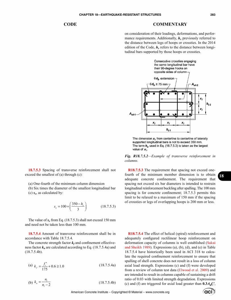
on consideration of their loadings, deformations, and perfor-mance requirements. Additionally, hx previously referred to the distance between legs of hoops or crossties. In the 2014 edition of the Code, hx refers to the distance between longi-tudinal bars supported by those hoops or crossties.
R18.7.5.3 The requirement that spacing not exceed one-fourth of the minimum member dimension is to obtain adequate concrete confinement. The requirement that spacing not exceed six bar diameters is intended to restrain longitudinal reinforcement buckling after spalling. The 100 mm spacing is for concrete confinement; 18.7.5.3 permits this limit to be relaxed to a maximum of 150 mm if the spacing of crossties or legs of overlapping hoops is 200 mm or less.
R18.7.5.4 The effect of helical (spiral) reinforcement and adequately configured rectilinear hoop reinforcement on deformation capacity of columns is well established (Sakai and Sheikh 1989). Expressions (a), (b), (d), and (e) in Table 18.7.5.4 have historically been used in ACI 318 to calcu-late the required confinement reinforcement to ensure that spalling of shell concrete does not result in a loss of column axial load strength. Expressions (c) and (f) were developed from a review of column test data (Elwood et al. 2009) and are intended to result in columns capable of sustaining a drift ratio of 0.03 with limited strength degradation. Expressions (c) and (f) are triggered for axial load greater than 0.3Agfc′,
18.7.5.3 Spacing of transverse reinforcement shall not exceed the smallest of (a) through (c):
(a) One-fourth of the minimum column dimension(b) Six times the diameter of the smallest longitudinal bar(c) so, as calculated by:
350
1003− = +
xo
hs (18.7.5.3)
The value of so from Eq. (18.7.5.3) shall not exceed 150 mm and need not be taken less than 100 mm.
18.7.5.4 Amount of transverse reinforcement shall be in accordance with Table 18.7.5.4.
The concrete strength factor kf and confinement effective-ness factor kn are calculated according to Eq. (18.7.5.4a) and (18.7.5.4b).
(a) 0.6 1.0175
= + ≥′c
fkf (18.7.5.4a)
(b) 2l
nl
nk
n=
− (18.7.5.4b)
Fig. R18.7.5.2—Example of transverse reinforcement in columns.
American Concrete Institute – Copyrighted © Material – www.concrete.org
CHAPTER 18—EARTHQUAKE-RESISTANT STRUCTURES 283
CODE COMMENTARY
18
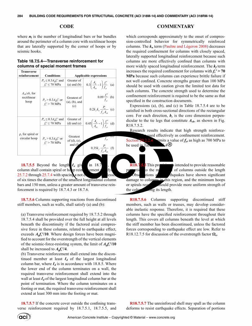
which corresponds approximately to the onset of compres-sion-controlled behavior for symmetrically reinforced columns. The kn term (Paultre and Légeron 2008) decreases the required confinement for columns with closely spaced, laterally supported longitudinal reinforcement because such columns are more effectively confined than columns with more widely spaced longitudinal reinforcement. The kf term increases the required confinement for columns with fc′ > 70 MPa because such columns can experience brittle failure if not well confined. Concrete strengths greater than 100 MPa should be used with caution given the limited test data for such columns. The concrete strength used to determine the confinement reinforcement is required to be the same as that specified in the construction documents.
Expressions (a), (b), and (c) in Table 18.7.5.4 are to be satisfied in both cross-sectional directions of the rectangular core. For each direction, bc is the core dimension perpen-dicular to the tie legs that constitute Ash, as shown in Fig. R18.7.5.2.
Research results indicate that high strength reinforce-ment can be used effectively as confinement reinforcement. Section 20.2.2.4 permits a value of fyt as high as 700 MPa to be used in Table 18.7.5.4
R18.7.5.5 This provision is intended to provide reasonable protection to the midheight of columns outside the length ℓo. Observations after earthquakes have shown significant damage to columns in this region, and the minimum hoops or spirals required should provide more uniform strength of the column along its length.
R18.7.5.6 Columns supporting discontinued stiff members, such as walls or trusses, may develop consider-able inelastic response. Therefore, it is required that these columns have the specified reinforcement throughout their length. This covers all columns beneath the level at which the stiff member has been discontinued, unless the factored forces corresponding to earthquake effect are low. Refer to R18.12.7.5 for discussion of the overstrength factor Ωo.
R18.7.5.7 The unreinforced shell may spall as the column deforms to resist earthquake effects. Separation of portions
where nl is the number of longitudinal bars or bar bundles around the perimeter of a column core with rectilinear hoops that are laterally supported by the corner of hoops or by seismic hooks.
Table 18.7.5.4—Transverse reinforcement for columns of special moment frames
Transverse reinforcement Conditions Applicable expressions
Ash/sbc for rectilinear
hoop
Pu ≤ 0.3Agfc′ andfc′ ≤ 70 MPa
Greater of (a) and (b) 0.3 1 (a) g
ch y
c
t
A fA f
−
′
0.09 (b)c
ytff ′
0.2 (c)uf n
yt ch
Pk kf A
Pu > 0.3Agfc′ orfc′ > 70 MPa
Greatest of (a), (b), and
(c)
ρs for spiral or circular hoop
Pu ≤ 0.3Agfc′ andfc′ ≤ 70 MPa
Greater of (d) and (e) 0.45 1 (d)
yt
cg
ch
AA
ff
′−
0.12 (e)c
ytff ′
0.35 (f)uf
yt ch
Pkf A
Pu > 0.3Agfc′ orfc′ > 70 MPa
Greatest of (d), (e),
and (f)
18.7.5.5 Beyond the length ℓo given in 18.7.5.1, the column shall contain spiral or hoop reinforcement satisfying 25.7.2 through 25.7.4 with spacing s not exceeding the lesser of six times the diameter of the smallest longitudinal column bars and 150 mm, unless a greater amount of transverse rein-forcement is required by 18.7.4.3 or 18.7.6.
18.7.5.6 Columns supporting reactions from discontinued stiff members, such as walls, shall satisfy (a) and (b):
(a) Transverse reinforcement required by 18.7.5.2 through 18.7.5.4 shall be provided over the full height at all levels beneath the discontinuity if the factored axial compres-sive force in these columns, related to earthquake effect, exceeds Agfc′/10. Where design forces have been magni-fied to account for the overstrength of the vertical elements of the seismic-force-resisting system, the limit of Agfc′/10 shall be increased to Agfc′/4.(b) Transverse reinforcement shall extend into the discon-tinued member at least ℓd of the largest longitudinal column bar, where ℓd is in accordance with 18.8.5. Where the lower end of the column terminates on a wall, the required transverse reinforcement shall extend into the wall at least ℓd of the largest longitudinal column bar at the point of termination. Where the column terminates on a footing or mat, the required transverse reinforcement shall extend at least 300 mm into the footing or mat.
18.7.5.7 If the concrete cover outside the confining trans-verse reinforcement required by 18.7.5.1, 18.7.5.5, and
American Concrete Institute – Copyrighted © Material – www.concrete.org
284 BUILDING CODE REQUIREMENTS FOR STRUCTURAL CONCRETE (ACI 318M-14) AND COMMENTARY (ACI 318RM-14)
CODE COMMENTARY
of the shell from the core caused by local spalling creates a falling hazard. The additional reinforcement is required to reduce the risk of portions of the shell falling away from the column.
R18.7.6 Shear strength
R18.7.6.1 Design forces
R18.7.6.1.1 The procedures of 18.6.5.1 also apply to columns. Above the ground floor, the moment at a joint may be limited by the flexural strength of the beams framing into the joint. Where beams frame into opposite sides of a joint, the combined strength is the sum of the negative moment strength of the beam on one side of the joint and the positive moment strength of the beam on the other side of the joint. Moment strengths are to be determined using a strength reduction factor of 1.0 and reinforcement with an effective yield stress equal to at least 1.25fy. Distribution of the combined moment strength of the beams to the columns above and below the joint should be based on analysis.
R18.8—Joints of special moment frames
R18.8.2 General—Development of inelastic rotations at the faces of joints of reinforced concrete frames is associated with strains in the flexural reinforcement well in excess of the yield strain. Consequently, joint shear force generated by the flexural reinforcement is calculated for a stress of 1.25fy in the reinforcement (refer to 18.8.2.1). A detailed explana-tion of the reasons for the possible development of stresses in excess of the yield strength in beam tensile reinforcement is provided in ACI 352R.
R18.8.2.2 The design provisions for hooked bars are based mainly on research and experience for joints with standard 90-degree hooks. Therefore, standard 90-degree hooks generally are preferred to standard 180-degree hooks unless unusual considerations dictate use of 180-degree hooks. For
18.7.5.6 exceeds 100 mm, additional transverse reinforce-ment having cover not exceeding 100 mm. and spacing not exceeding 300 mm shall be provided.
18.7.6 Shear strength
18.7.6.1 Design forces
18.7.6.1.1 The design shear force Ve shall be calculated from considering the maximum forces that can be generated at the faces of the joints at each end of the column. These joint forces shall be calculated using the maximum probable flexural strengths, Mpr, at each end of the column associ-ated with the range of factored axial forces, Pu, acting on the column. The column shears need not exceed those calculated from joint strengths based on Mpr of the beams framing into the joint. In no case shall Ve be less than the factored shear calculated by analysis of the structure.
18.7.6.2 Transverse reinforcement
18.7.6.2.1 Transverse reinforcement over the lengths ℓo, given in 18.7.5.1, shall be designed to resist shear assuming Vc = 0 when both (a) and (b) occur:
(a) The earthquake-induced shear force, calculated in accordance with 18.7.6.1, is at least one-half of the maximum required shear strength within ℓo.(b) The factored axial compressive force Pu including earthquake effects is less than Agfc′/20.
18.8—Joints of special moment frames 18.8.1 Scope
18.8.1.1 This section shall apply to beam-column joints of special moment frames forming part of the seismic-force-resisting system.
18.8.2 General
18.8.2.1 Forces in longitudinal beam reinforcement at the joint face shall be calculated assuming that the stress in the flexural tensile reinforcement is 1.25fy.
18.8.2.2 Beam longitudinal reinforcement terminated in a column shall extend to the far face of the confined column core and shall be developed in tension in accordance with 18.8.5 and in compression in accordance with 25.4.9.
American Concrete Institute – Copyrighted © Material – www.concrete.org
CHAPTER 18—EARTHQUAKE-RESISTANT STRUCTURES 285
CODE COMMENTARY
18
bars in compression, the development length corresponds to the straight portion of a hooked or headed bar measured from the critical section to the onset of the bend for hooked bars and from the critical section to the head for headed bars.
R18.8.2.3 Research (Meinheit and Jirsa 1977; Briss et al. 1978; Ehsani 1982; Durrani and Wight 1982; Leon 1989) has shown that straight beam bars may slip within the beam-column joint during a series of large moment rever-sals. The bond stresses on these straight bars may be very large. To reduce slip substantially during the formation of adjacent beam hinging, it would be necessary to have a ratio of column dimension to bar diameter of approximately 32, which would result in very large joints. On reviewing the available tests, the required minimum ratio of column depth to maximum beam longitudinal bar diameter was set at 20 for normalweight concrete and 26 for lightweight concrete. Due to the lack of specific data for beam bars through light-weight concrete joints, the limit is based on an amplification factor of 1.3, which is approximately the reciprocal of the lightweight concrete modification factor of 19.2.4. These limits provide reasonable control on the amount of potential slip of the beam bars in a beam-column joint, considering the number of anticipated inelastic excursions of the building frames during a major earthquake. A thorough treatment of this topic is given in Zhu and Jirsa (1983).
R18.8.2.4 Depth h of the joint is defined in Fig. R18.8.4. The requirement on joint aspect ratio applies only to beams that are designated as part of the seismic-force-resisting system. Joints having depth less than half the beam depth require a steep diagonal compression strut across the joint, which may be less effective in resisting joint shear. Tests to demonstrate performance of such joints have not been reported in the literature.
R18.8.3 Transverse reinforcement—The Code requires transverse reinforcement in a joint regardless of the magni-tude of the calculated shear force.
R18.8.3.2 The amount of confining reinforcement may be reduced and the spacing may be increased if beams of adequate dimensions frame into all four sides of the joint.
R18.8.3.3 The required transverse reinforcement, or transverse beam if present, is intended to confine the beam longitudinal reinforcement and improve force transfer to the beam-column joint.
An example of transverse reinforcement through the column provided to confine the beam reinforcement passing
18.8.2.3 Where longitudinal beam reinforcement extends through a beam-column joint, the column dimension parallel to the beam reinforcement shall be at least 20 times the diam-eter of the largest longitudinal beam bar for normalweight concrete or 26 times the diameter of the largest longitudinal bar for lightweight concrete.
18.8.2.4 Depth h of the joint shall not be less than one-half of depth h of any beam framing into the joint and generating joint shear as part of the seismic-force-resisting system.
18.8.3 Transverse reinforcement
18.8.3.1 Joint transverse reinforcement shall satisfy 18.7.5.2, 18.7.5.3, 18.7.5.4, and 18.7.5.7, except as permitted in 18.8.3.2.
18.8.3.2 Where beams frame into all four sides of the joint and where each beam width is at least three-fourths the column width, the amount of reinforcement required by 18.7.5.4 shall be permitted to be reduced by one-half, and the spacing required by 18.7.5.3 shall be permitted to be increased to 150 mm within the overall depth h of the shal-lowest framing beam.
18.8.3.3 Longitudinal beam reinforcement outside the column core shall be confined by transverse reinforcement passing through the column that satisfies spacing require-ments of 18.6.4.4, and requirements of 18.6.4.2, and 18.6.4.3, if such confinement is not provided by a beam framing into the joint.
American Concrete Institute – Copyrighted © Material – www.concrete.org
286 BUILDING CODE REQUIREMENTS FOR STRUCTURAL CONCRETE (ACI 318M-14) AND COMMENTARY (ACI 318RM-14)
CODE COMMENTARY
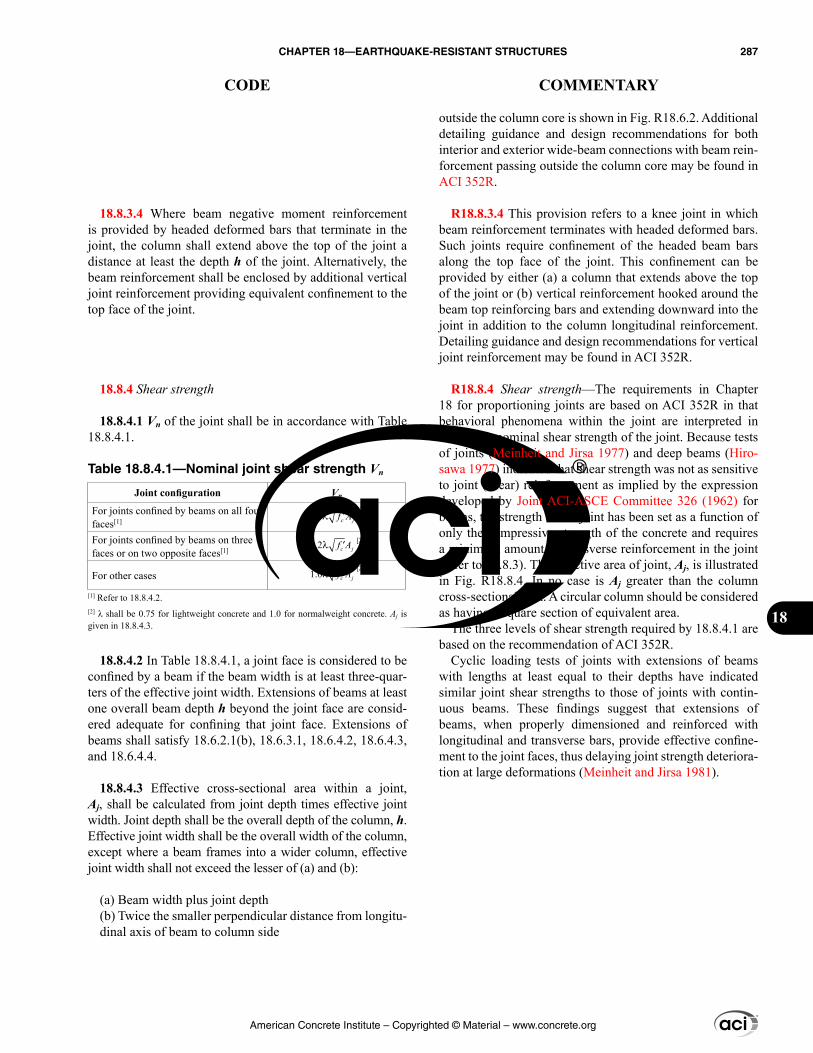
18.8.3.4 Where beam negative moment reinforcement is provided by headed deformed bars that terminate in the joint, the column shall extend above the top of the joint a distance at least the depth h of the joint. Alternatively, the beam reinforcement shall be enclosed by additional vertical joint reinforcement providing equivalent confinement to the top face of the joint.
18.8.4 Shear strength
18.8.4.1 Vn of the joint shall be in accordance with Table 18.8.4.1.
Table 18.8.4.1—Nominal joint shear strength Vn
Joint configuration Vn
For joints confined by beams on all four faces[1] 1.7λ ′c jf A
[2]
For joints confined by beams on three faces or on two opposite faces[1]
1.2λ ′c jf A [2]
For other cases 1.0λ ′c jf A[2]
[1] Refer to 18.8.4.2.[2] λ shall be 0.75 for lightweight concrete and 1.0 for normalweight concrete. Aj is given in 18.8.4.3.
18.8.4.2 In Table 18.8.4.1, a joint face is considered to be confined by a beam if the beam width is at least three-quar-ters of the effective joint width. Extensions of beams at least one overall beam depth h beyond the joint face are consid-ered adequate for confining that joint face. Extensions of beams shall satisfy 18.6.2.1(b), 18.6.3.1, 18.6.4.2, 18.6.4.3, and 18.6.4.4.
18.8.4.3 Effective cross-sectional area within a joint, Aj, shall be calculated from joint depth times effective joint width. Joint depth shall be the overall depth of the column, h. Effective joint width shall be the overall width of the column, except where a beam frames into a wider column, effective joint width shall not exceed the lesser of (a) and (b):
(a) Beam width plus joint depth(b) Twice the smaller perpendicular distance from longitu-dinal axis of beam to column side
outside the column core is shown in Fig. R18.6.2. Additional detailing guidance and design recommendations for both interior and exterior wide-beam connections with beam rein-forcement passing outside the column core may be found in ACI 352R.
R18.8.3.4 This provision refers to a knee joint in which beam reinforcement terminates with headed deformed bars. Such joints require confinement of the headed beam bars along the top face of the joint. This confinement can be provided by either (a) a column that extends above the top of the joint or (b) vertical reinforcement hooked around the beam top reinforcing bars and extending downward into the joint in addition to the column longitudinal reinforcement. Detailing guidance and design recommendations for vertical joint reinforcement may be found in ACI 352R.
R18.8.4 Shear strength—The requirements in Chapter 18 for proportioning joints are based on ACI 352R in that behavioral phenomena within the joint are interpreted in terms of a nominal shear strength of the joint. Because tests of joints (Meinheit and Jirsa 1977) and deep beams (Hiro-sawa 1977) indicated that shear strength was not as sensitive to joint (shear) reinforcement as implied by the expression developed by Joint ACI-ASCE Committee 326 (1962) for beams, the strength of the joint has been set as a function of only the compressive strength of the concrete and requires a minimum amount of transverse reinforcement in the joint (refer to 18.8.3). The effective area of joint, Aj, is illustrated in Fig. R18.8.4. In no case is Aj greater than the column cross-sectional area. A circular column should be considered as having a square section of equivalent area.
The three levels of shear strength required by 18.8.4.1 are based on the recommendation of ACI 352R.
Cyclic loading tests of joints with extensions of beams with lengths at least equal to their depths have indicated similar joint shear strengths to those of joints with contin-uous beams. These findings suggest that extensions of beams, when properly dimensioned and reinforced with longitudinal and transverse bars, provide effective confine-ment to the joint faces, thus delaying joint strength deteriora-tion at large deformations (Meinheit and Jirsa 1981).
American Concrete Institute – Copyrighted © Material – www.concrete.org
CHAPTER 18—EARTHQUAKE-RESISTANT STRUCTURES 287
CODE COMMENTARY
18
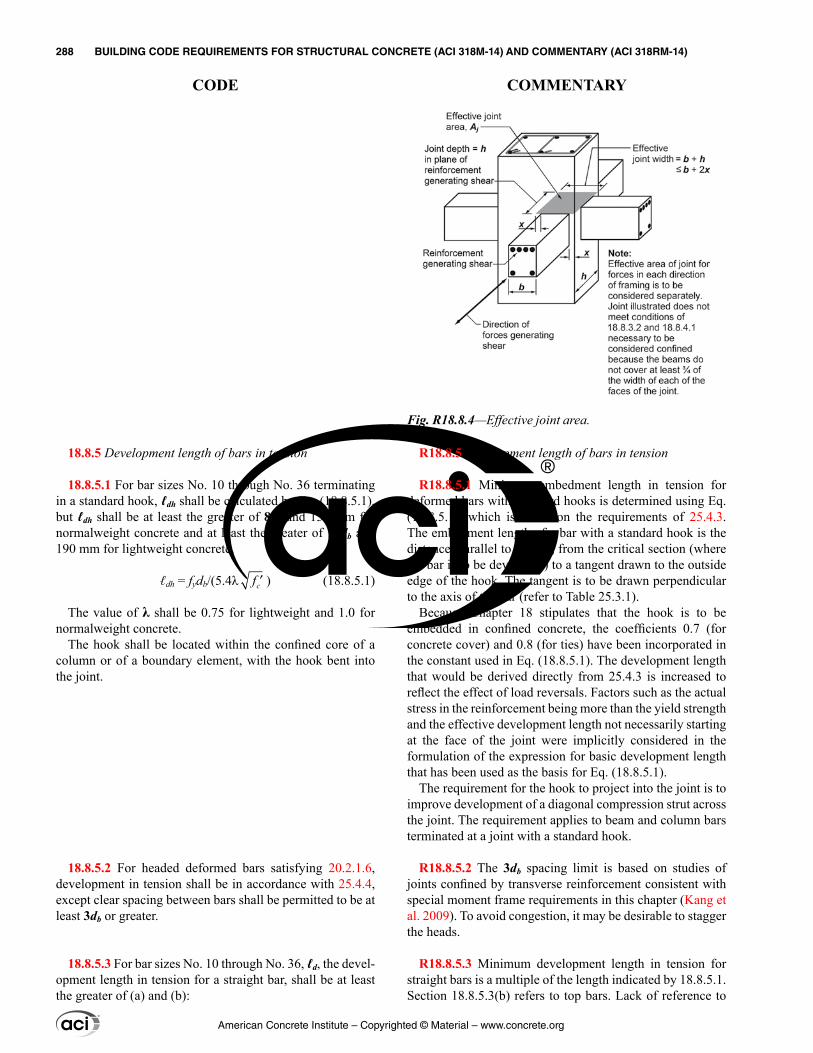
18.8.5 Development length of bars in tension
18.8.5.1 For bar sizes No. 10 through No. 36 terminating in a standard hook, ℓdh shall be calculated by Eq. (18.8.5.1), but ℓdh shall be at least the greater of 8db and 150 mm for normalweight concrete and at least the greater of 10db and 190 mm for lightweight concrete.
ℓdh = fydb/(5.4λ cf ′ ) (18.8.5.1)
The value of λ shall be 0.75 for lightweight and 1.0 for normalweight concrete.
The hook shall be located within the confined core of a column or of a boundary element, with the hook bent into the joint.
18.8.5.2 For headed deformed bars satisfying 20.2.1.6, development in tension shall be in accordance with 25.4.4, except clear spacing between bars shall be permitted to be at least 3db or greater.
18.8.5.3 For bar sizes No. 10 through No. 36, ℓd, the devel-opment length in tension for a straight bar, shall be at least the greater of (a) and (b):
R18.8.5 Development length of bars in tension
R18.8.5.1 Minimum embedment length in tension for deformed bars with standard hooks is determined using Eq. (18.8.5.1), which is based on the requirements of 25.4.3. The embedment length of a bar with a standard hook is the distance, parallel to the bar, from the critical section (where the bar is to be developed) to a tangent drawn to the outside edge of the hook. The tangent is to be drawn perpendicular to the axis of the bar (refer to Table 25.3.1).
Because Chapter 18 stipulates that the hook is to be embedded in confined concrete, the coefficients 0.7 (for concrete cover) and 0.8 (for ties) have been incorporated in the constant used in Eq. (18.8.5.1). The development length that would be derived directly from 25.4.3 is increased to reflect the effect of load reversals. Factors such as the actual stress in the reinforcement being more than the yield strength and the effective development length not necessarily starting at the face of the joint were implicitly considered in the formulation of the expression for basic development length that has been used as the basis for Eq. (18.8.5.1).
The requirement for the hook to project into the joint is to improve development of a diagonal compression strut across the joint. The requirement applies to beam and column bars terminated at a joint with a standard hook.
R18.8.5.2 The 3db spacing limit is based on studies of joints confined by transverse reinforcement consistent with special moment frame requirements in this chapter (Kang et al. 2009). To avoid congestion, it may be desirable to stagger the heads.
R18.8.5.3 Minimum development length in tension for straight bars is a multiple of the length indicated by 18.8.5.1. Section 18.8.5.3(b) refers to top bars. Lack of reference to
Fig. R18.8.4—Effective joint area.
American Concrete Institute – Copyrighted © Material – www.concrete.org
288 BUILDING CODE REQUIREMENTS FOR STRUCTURAL CONCRETE (ACI 318M-14) AND COMMENTARY (ACI 318RM-14)
CODE COMMENTARY
(a) 2.5 times the length in accordance with 18.8.5.1 if the depth of the concrete cast in one lift beneath the bar does not exceed 300 mm(b) 3.25 times the length in accordance with 18.8.5.1 if the depth of the concrete cast in one lift beneath the bar exceeds 300 mm
18.8.5.4 Straight bars terminated at a joint shall pass through the confined core of a column or a boundary element. Any portion of ℓd not within the confined core shall be increased by a factor of 1.6.
18.8.5.5 If epoxy-coated reinforcement is used, the devel-opment lengths in 18.8.5.1, 18.8.5.3, and 18.8.5.4 shall be multiplied by applicable factors in 25.4.2.4 or 25.4.3.2.
18.9—Special moment frames constructed using precast concrete
18.9.1 Scope
18.9.1.1 This section shall apply to special moment frames constructed using precast concrete forming part of the seismic-force-resisting system.
No. 43 and No. 57 bars in 18.8.5 is due to the paucity of information on anchorage of such bars subjected to load reversals simulating earthquake effects.
R18.8.5.4 If the required straight embedment length of a reinforcing bar extends beyond the confined volume of concrete (as defined in 18.6.4, 18.7.5, or 18.8.3), the required development length is increased on the premise that the limiting bond stress outside the confined region is less than that inside.
ℓdm = 1.6(ℓd – ℓdc) + ℓdc
or
ℓdm = 1.6ℓd – 0.6ℓdc
where ℓdm is the required development length if bar is not entirely embedded in confined concrete; ℓd is the required development length in tension for straight bar as defined in 18.8.5.3; and ℓdc is the length of bar embedded in confined concrete.
R18.9—Special moment frames constructed using precast concrete
The detailing provisions in 18.9.2.1 and 18.9.2.2 are intended to produce frames that respond to design displace-ments essentially like monolithic special moment frames.
Precast frame systems composed of concrete elements with ductile connections are expected to experience flexural yielding in connection regions. Reinforcement in ductile connections can be made continuous by using Type 2 mechan-ical splices or any other technique that provides development in tension or compression of at least the specified tensile strength of bars (Yoshioka and Sekine 1991; Kurose et al. 1991; Restrepo et al. 1995a,b). Requirements for mechanical splices are in addition to those in 18.2.7 and are intended to avoid strain concentrations over a short length of reinforce-ment adjacent to a splice device. Additional requirements for shear strength are provided in 18.9.2.1 to prevent sliding on connection faces. Precast frames composed of elements with ductile connections may be designed to promote yielding at locations not adjacent to the joints. Therefore, design shear Ve, as calculated according to 18.6.5.1 or 18.7.6.1, may not be conservative.
Precast concrete frame systems composed of elements joined using strong connections are intended to experience flexural yielding outside the connections. Strong connec-tions include the length of the mechanical splice hardware
American Concrete Institute – Copyrighted © Material – www.concrete.org
CHAPTER 18—EARTHQUAKE-RESISTANT STRUCTURES 289
CODE COMMENTARY
18
18.9.2 General
18.9.2.1 Special moment frames with ductile connections constructed using precast concrete shall satisfy (a) through (c):
(a) Requirements of 18.6 through 18.8 for special moment frames constructed with cast-in-place concrete(b) Vn for connections calculated according to 22.9 shall be at least 2Ve, where Ve is in accordance with 18.6.5.1 or 18.7.6.1(c) Mechanical splices of beam reinforcement shall be located not closer than h/2 from the joint face and shall satisfy 18.2.7
18.9.2.2 Special moment frames with strong connections constructed using precast concrete shall satisfy (a) through (e):
(a) Requirements of 18.6 through 18.8 for special moment frames constructed with cast-in-place concrete(b) Provision 18.6.2.1(a) shall apply to segments between locations where flexural yielding is intended to occur due to design displacements(c) Design strength of the strong connection, ϕSn, shall be at least Se(d) Primary longitudinal reinforcement shall be made continuous across connections and shall be developed outside both the strong connection and the plastic hinge region(e) For column-to-column connections, ϕSn shall be at least 1.4Se, ϕMn shall be at least 0.4Mpr for the column within the story height, and ϕVn shall be at least Ve in accordance with 18.7.6.1
as shown in Fig. R18.9.2.2. Capacity-design techniques are used in 18.9.2.2(c) to ensure the strong connection remains elastic following formation of plastic hinges. Additional column requirements are provided to avoid hinging and strength deterioration of column-to-column connections.
Strain concentrations have been observed to cause brittle fracture of reinforcing bars at the face of mechanical splices in laboratory tests of precast beam-column connections (Palmieri et al. 1996). Locations of strong connections should be selected carefully or other measures should be taken, such as debonding of reinforcing bars in highly stressed regions, to avoid strain concentrations that can result in premature fracture of reinforcement.
R18.9.2 General
American Concrete Institute – Copyrighted © Material – www.concrete.org
290 BUILDING CODE REQUIREMENTS FOR STRUCTURAL CONCRETE (ACI 318M-14) AND COMMENTARY (ACI 318RM-14)
CODE COMMENTARY
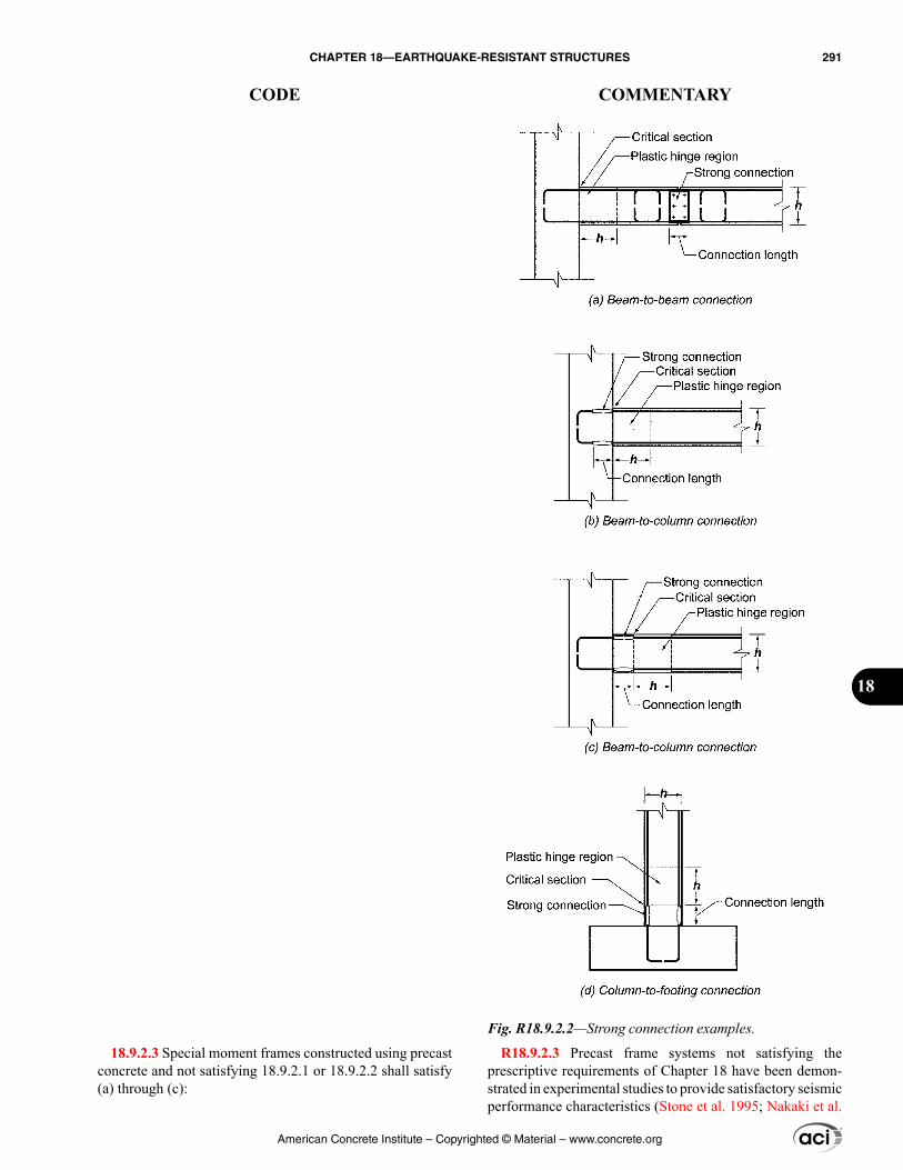
18.9.2.3 Special moment frames constructed using precast concrete and not satisfying 18.9.2.1 or 18.9.2.2 shall satisfy (a) through (c):
R18.9.2.3 Precast frame systems not satisfying the prescriptive requirements of Chapter 18 have been demon-strated in experimental studies to provide satisfactory seismic performance characteristics (Stone et al. 1995; Nakaki et al.
Fig. R18.9.2.2—Strong connection examples.
American Concrete Institute – Copyrighted © Material – www.concrete.org
CHAPTER 18—EARTHQUAKE-RESISTANT STRUCTURES 291
CODE COMMENTARY
18
(a) ACI 374.1(b) Details and materials used in the test specimens shall be representative of those used in the structure(c) The design procedure used to proportion the test speci-mens shall define the mechanism by which the frame resists gravity and earthquake effects, and shall establish acceptance values for sustaining that mechanism. Portions of the mechanism that deviate from Code requirements shall be contained in the test specimens and shall be tested to determine upper bounds for acceptance values.
18.10—Special structural walls 18.10.1 Scope
18.10.1.1 This section shall apply to special struc-tural walls and all components of special structural walls including coupling beams and wall piers forming part of the seismic-force-resisting system.
18.10.1.2 Special structural walls constructed using precast concrete shall be in accordance with 18.11 in addi-tion to 18.10.
18.10.2 Reinforcement
18.10.2.1 The distributed web reinforcement ratios, ρℓ and ρt, for structural walls shall be at least 0.0025, except that if Vu does not exceed 0.083Acvλ ′fc , ρℓ and ρt shall be permitted to be reduced to the values in 11.6. Reinforcement spacing each way in structural walls shall not exceed 450 mm. Reinforcement contributing to Vn shall be continuous and shall be distributed across the shear plane.
1995). ACI 374.1 defines a protocol for establishing a design procedure, validated by analysis and laboratory tests, for such frames. The design procedure should identify the load path or mechanism by which the frame resists gravity and earthquake effects. The tests should be configured to inves-tigate critical behaviors, and the measured quantities should establish upper-bound acceptance values for components of the load path, which may be in terms of limiting stresses, forces, strains, or other quantities. The design procedure used for the structure should not deviate from that used to design the test specimens, and acceptance values should not exceed values that were demonstrated by the tests to be acceptable. Materials and components used in the structure should be similar to those used in the tests. Deviations may be accept-able if the licensed design professional can demonstrate that those deviations do not adversely affect the behavior of the framing system.
ACI 550.3 defines design requirements for one type of special precast concrete moment frame for use in accordance with 18.9.2.3.
R18.10—Special structural walls R18.10.1 Scope—This section contains requirements for
the dimensions and details of special structural walls and all components including coupling beams and wall piers. Wall piers are defined in Chapter 2. Design provisions for vertical wall segments depend on the aspect ratio of the wall segment in the plane of the wall (hw/ℓw), and the aspect ratio of the horizontal cross section (ℓw/bw), and generally follow the descriptions in Table R18.10.1. The limiting aspect ratios for wall piers are based on engineering judgment. It is intended that flexural yielding of the vertical reinforcement in the pier should limit shear demand on the pier.
R18.10.2 Reinforcement—Minimum reinforcement requirements in 18.10.2.1 follow from preceding Codes. The requirement for distributed shear reinforcement is related to the intent to control the width of inclined cracks. The requirement for two layers of reinforcement in walls resisting substantial design shears in 18.10.2.2 is based on the observation that, under ordinary construction condi-tions, the probability of maintaining a single layer of rein-forcement near the middle of the wall section is quite low. Furthermore, presence of reinforcement close to the surface
Table R18.10.1—Governing design provisions for vertical wall segments[1]
Clear height of vertical wall segment/length of vertical
wall segment, (hw/ℓw)
Length of vertical wall segment/wall thickness (ℓw/bw)
(ℓw/bw) ≤ 2.5 2.5 < (ℓw/bw) ≤ 6.0 (ℓw/bw) > 6.0
hw/ℓw < 2.0 Wall Wall Wall
hw/ℓw ≥ 2.0
Wall pier required to satisfy specified column design
requirements; refer to 18.10.8.1
Wall pier required to satisfy specified column design
requirements or alternative requirements; refer to
18.10.8.1
Wall
[1]hw is the clear height, ℓw is the horizontal length, and bw is the width of the web of the wall segment.
American Concrete Institute – Copyrighted © Material – www.concrete.org
292 BUILDING CODE REQUIREMENTS FOR STRUCTURAL CONCRETE (ACI 318M-14) AND COMMENTARY (ACI 318RM-14)
CODE COMMENTARY
18.10.2.2 At least two curtains of reinforcement shall be used in a wall if Vu > 0.17Acvλ ′fc or hw/ℓw ≥ 2.0, in which hw and ℓw refer to height and length of entire wall, respectively.
18.10.2.3 Reinforcement in structural walls shall be devel-oped or spliced for fy in tension in accordance with 25.4, 25.5, and (a) through (c):
(a) Longitudinal reinforcement shall extend beyond the point at which it is no longer required to resist flexure by least 0.8ℓw, except at the top of a wall(b) At locations where yielding of longitudinal reinforce-ment is likely to occur as a result of lateral displacements, development lengths of longitudinal reinforcement shall be 1.25 times the values calculated for fy in tension(c) Mechanical splices of reinforcement shall conform to 18.2.7 and welded splices of reinforcement shall conform to 18.2.8
18.10.3 Design forces—Vu shall be obtained from the lateral load analysis in accordance with the factored load combinations.
18.10.4 Shear strength
18.10.4.1 Vn of structural walls shall not exceed:
( )n cv c c t yV A f f= α λ + ρ′ (18.10.4.1)
where the coefficient αc is 0.25 for hw/ℓw ≤ 1.5, is 0.17 for hw/ℓw ≥ 2.0, and varies linearly between 0.25 and 0.17 for hw/ℓw between 1.5 and 2.0.
18.10.4.2 In 18.10.4.1, the value of ratio hw/ℓw used to calculate Vn for segments of a wall shall be the greater of the ratios for the entire wall and the segment of wall considered.
18.10.4.3 Walls shall have distributed shear reinforcement in two orthogonal directions in the plane of the wall. If hw/ℓw does not exceed 2.0, reinforcement ratio ρℓ shall be at least the reinforcement ratio ρt.
18.10.4.4 For all vertical wall segments sharing a common lateral force, Vn shall not be taken greater than 0.66Acv ′fc , where Acv is the gross area of concrete bounded by web thick-ness and length of section. For any one of the individual vertical wall segments, Vn shall not be taken greater than 0.83Acw ′fc
tends to inhibit fragmentation of the concrete in the event of severe cracking during an earthquake. The requirement for two layers of vertical reinforcement in more slender walls is to improve lateral stability of the compression zone under cyclic loads following yielding of vertical reinforcement in tension.
R18.10.2.3 Requirements are based on provisions in Chapter 25. Because actual forces in longitudinal reinforce-ment of structural walls may exceed calculated forces, rein-forcement should be developed or spliced to reach the yield strength of the bar in tension. At locations where yielding of longitudinal reinforcement is expected, a 1.25 multiplier is applied to account for the likelihood that the actual yield strength exceeds the specified yield strength of the bar, as well as the influence of strain hardening and cyclic load reversals. Where transverse reinforcement is used, develop-ment lengths for straight and hooked bars may be reduced as permitted in 25.4.2 and 25.4.3, respectively, because closely spaced transverse reinforcement improves the performance of splices and hooks subjected to repeated inelastic demands (ACI 408.2R).
R18.10.3 Design forces—Design shears for structural walls are obtained from lateral load analysis with the appro-priate load factors. However, the possibility of yielding in components of such structures should be considered, as in the portion of a wall between two window openings, in which case the actual shear may be in excess of the shear indicated by lateral load analysis based on factored design forces.
R18.10.4 Shear strength—Equation (18.10.4.1) recog-nizes the higher shear strength of walls with high shear-to-moment ratios (Hirosawa 1977; Joint ACI-ASCE Committee 326 1962; Barda et al. 1977). The nominal shear strength is given in terms of the net area of the section resisting shear. For a rectangular section without openings, the term Acv refers to the gross area of the cross section rather than to the product of the width and the effective depth. The defini-tion of Acv in Eq. (18.10.4.1) facilitates design calculations for walls with uniformly distributed reinforcement and walls with openings.
A vertical wall segment refers to a part of a wall bounded horizontally by openings or by an opening and an edge. For an isolated wall or a vertical wall segment, ρt refers to hori-zontal reinforcement and ρℓ refers to vertical reinforcement.
The ratio hw/ℓw may refer to overall dimensions of a wall, or of a segment of the wall bounded by two openings, or an opening and an edge. The intent of 18.10.4.2 is to make certain that any segment of a wall is not assigned a unit strength greater than that for the entire wall. However, a wall segment with a ratio of hw/ℓw higher than that of the entire wall should be proportioned for the unit strength asso-ciated with the ratio hw/ℓw based on the dimensions for that segment.
American Concrete Institute – Copyrighted © Material – www.concrete.org
CHAPTER 18—EARTHQUAKE-RESISTANT STRUCTURES 293
CODE COMMENTARY
18
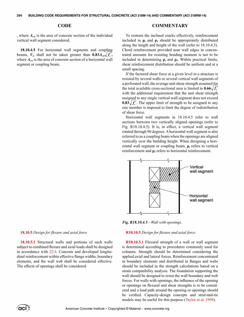
To restrain the inclined cracks effectively, reinforcement included in ρt and ρℓ should be appropriately distributed along the length and height of the wall (refer to 18.10.4.3). Chord reinforcement provided near wall edges in concen-trated amounts for resisting bending moment is not to be included in determining ρt and ρℓ. Within practical limits, shear reinforcement distribution should be uniform and at a small spacing.
If the factored shear force at a given level in a structure is resisted by several walls or several vertical wall segments of a perforated wall, the average unit shear strength assumed for the total available cross-sectional area is limited to 0.66 ′fc with the additional requirement that the unit shear strength assigned to any single vertical wall segment does not exceed 0.83 ′fc . The upper limit of strength to be assigned to any one member is imposed to limit the degree of redistribution of shear force.
Horizontal wall segments in 18.10.4.5 refer to wall sections between two vertically aligned openings (refer to Fig. R18.10.4.5). It is, in effect, a vertical wall segment rotated through 90 degrees. A horizontal wall segment is also referred to as a coupling beam when the openings are aligned vertically over the building height. When designing a hori-zontal wall segment or coupling beam, ρt refers to vertical reinforcement and ρℓ refers to horizontal reinforcement.
R18.10.5 Design for flexure and axial force
R18.10.5.1 Flexural strength of a wall or wall segment is determined according to procedures commonly used for columns. Strength should be determined considering the applied axial and lateral forces. Reinforcement concentrated in boundary elements and distributed in flanges and webs should be included in the strength calculations based on a strain compatibility analysis. The foundation supporting the wall should be designed to resist the wall boundary and web forces. For walls with openings, the influence of the opening or openings on flexural and shear strengths is to be consid-ered and a load path around the opening or openings should be verified. Capacity-design concepts and strut-and-tie models may be useful for this purpose (Taylor et al. 1998).
, where Acw is the area of concrete section of the individual vertical wall segment considered.
18.10.4.5 For horizontal wall segments and coupling beams, Vn shall not be taken greater than 0.83Acw ′fc , where Acw is the area of concrete section of a horizontal wall segment or coupling beam.
18.10.5 Design for flexure and axial force
18.10.5.1 Structural walls and portions of such walls subject to combined flexure and axial loads shall be designed in accordance with 22.4. Concrete and developed longitu-dinal reinforcement within effective flange widths, boundary elements, and the wall web shall be considered effective. The effects of openings shall be considered.
Fig. R18.10.4.5—Wall with openings.
American Concrete Institute – Copyrighted © Material – www.concrete.org
294 BUILDING CODE REQUIREMENTS FOR STRUCTURAL CONCRETE (ACI 318M-14) AND COMMENTARY (ACI 318RM-14)
CODE COMMENTARY
R18.10.5.2 Where wall sections intersect to form L-, T-, C-, or other cross-sectional shapes, the influence of the flange on the behavior of the wall should be considered by selecting appropriate flange widths. Tests (Wallace 1996) show that effective flange width increases with increasing drift level and the effectiveness of a flange in compression differs from that for a flange in tension. The value used for the effective compression flange width has little effect on the strength and deformation capacity of the wall; therefore, to simplify design, a single value of effective flange width based on an estimate of the effective tension flange width is used in both tension and compression.
R18.10.6 Boundary elements of special structural walls
R18.10.6.1 Two design approaches for evaluating detailing requirements at wall boundaries are included in 18.10.6.1. Provision 18.10.6.2 allows the use of displace-ment-based design of walls, in which the structural details are determined directly on the basis of the expected lateral displacements of the wall. The provisions of 18.10.6.3 are similar to those of the 1995 Code, and have been retained because they are conservative for assessing required trans-verse reinforcement at wall boundaries for many walls. Provisions 18.10.6.4 and 18.10.6.5 apply to structural walls designed by either 18.10.6.2 or 18.10.6.3.
R18.10.6.2 This section is based on the assumption that inelastic response of the wall is dominated by flexural action at a critical, yielding section. The wall should be propor-tioned so that the critical section occurs where intended.
Equation (18.10.6.2) follows from a displacement-based approach (Moehle 1992; Wallace and Orakcal 2002). The approach assumes that special boundary elements are required to confine the concrete where the strain at the extreme compression fiber of the wall exceeds a critical value when the wall is displaced to 1.5 times the design displacement. The multiplier of 1.5 on design displacement was added to Equation (18.10.6.2) in the 2014 version of this Code to produce detailing requirements more consistent with the building code performance intent of a low prob-ability of collapse in Maximum Considered Earthquake level shaking. The lower limit of 0.005 on the quantity δu/hw requires special boundary elements if wall boundary longi-tudinal reinforcement tensile strain does not reach approxi-mately twice the limit used to define tension-controlled beam sections according to 21.2.2. The lower limit of 0.005 on the quantity δu/hw requires moderate wall deformation capacity for stiff buildings.
The neutral axis depth c in Eq. (18.10.6.2) is the depth calculated according to 22.2 corresponding to development of nominal flexural strength of the wall when displaced in the same direction as δu. The axial load is the factored axial load that is consistent with the design load combination that produces the design displacement δu.
18.10.5.2 Unless a more detailed analysis is performed, effective flange widths of flanged sections shall extend from the face of the web a distance equal to the lesser of one-half the distance to an adjacent wall web and 25 percent of the total wall height.
18.10.6 Boundary elements of special structural walls
18.10.6.1 The need for special boundary elements at the edges of structural walls shall be evaluated in accordance with 18.10.6.2 or 18.10.6.3. The requirements of 18.10.6.4 and 18.10.6.5 shall also be satisfied.
18.10.6.2 Walls or wall piers with hw/ℓw ≥ 2.0 that are effectively continuous from the base of structure to top of wall and are designed to have a single critical section for flexure and axial loads shall satisfy (a) and (b) or shall be designed by 18.10.6.3:
(a) Compression zones shall be reinforced with special boundary elements where
( )600 1.5 /w
u w
ch
≥δ
l (18.10.6.2)
and c corresponds to the largest neutral axis depth calcu-lated for the factored axial force and nominal moment strength consistent with the direction of the design displacement δu. Ratio δu/hw shall not be taken less than 0.005.(b) Where special boundary elements are required by (a), the special boundary element transverse reinforcement shall extend vertically above and below the critical section at least the greater of ℓw and Mu/4Vu, except as permitted in 18.10.6.4(g).
American Concrete Institute – Copyrighted © Material – www.concrete.org
CHAPTER 18—EARTHQUAKE-RESISTANT STRUCTURES 295
CODE COMMENTARY
18
The height of the special boundary element is based on estimates of plastic hinge length and extends beyond the zone over which yielding of tension reinforcement and spalling of concrete are likely to occur.
R18.10.6.3 By this procedure, the wall is considered to be acted on by gravity loads and the maximum shear and moment induced by earthquake in a given direction. Under this loading, the compressed boundary at the critical section resists the tributary gravity load plus the compressive resul-tant associated with the bending moment.
Recognizing that this loading condition may be repeated many times during the strong motion, the concrete is to be confined where the calculated compressive stresses exceed a nominal critical value equal to 0.2fc′. The stress is to be calculated for the factored forces on the section assuming linear response of the gross concrete section. The compres-sive stress of 0.2fc′ is used as an index value and does not necessarily describe the actual state of stress that may develop at the critical section under the influence of the actual inertia forces for the anticipated earthquake intensity.
R18.10.6.4 The horizontal dimension of the special boundary element is intended to extend at least over the length where the concrete compressive strain exceeds the critical value. For flanged wall sections, including box shapes, L-shapes, and C-shapes, the calculation to deter-mine the need for special boundary elements should include a direction of lateral load consistent with the orthogonal combinations defined in ASCE/SEI 7. The value of c/2 in 18.10.6.4(a) is to provide a minimum length of the special boundary element. Good detailing practice is to arrange the longitudinal reinforcement and the confinement reinforce-ment such that all primary longitudinal reinforcement at the wall boundary is supported by transverse reinforcement.
A slenderness limit is introduced into the 2014 edition of this Code based on lateral instability failures of slender wall boundaries observed in recent earthquakes and tests (Wallace 2012; Wallace et al. 2012). For walls with large cover, where spalling of cover concrete would lead to a significantly reduced section, increased boundary element thickness should be considered.
A value of c/ℓw ≥ 3/8 is used to define a wall critical section that is not tension-controlled according to 21.2.2. A minimum wall thickness of 300 mm is imposed to reduce the likelihood of lateral instability of the compression zone after spalling of cover concrete.
Where flanges are highly stressed in compression, the web-to-flange interface is likely to be highly stressed and may sustain local crushing failure unless special boundary element reinforcement extends into the web.
Required transverse reinforcement at wall boundaries is based on column provisions. Expression (a) of Table 18.10.6.4(f) was applied to wall special boundary elements prior to the 1999 edition of this Code. It is reinstated in the 2014 edition of this Code due to concerns that expression
18.10.6.3 Structural walls not designed in accordance with 18.10.6.2 shall have special boundary elements at bound-aries and edges around openings of structural walls where the maximum extreme fiber compressive stress, corre-sponding to load combinations including earthquake effects E, exceeds 0.2fc′. The special boundary element shall be permitted to be discontinued where the calculated compres-sive stress is less than 0.15fc′. Stresses shall be calculated for the factored loads using a linearly elastic model and gross section properties. For walls with flanges, an effective flange width as given in 18.10.5.2 shall be used.
18.10.6.4 Where special boundary elements are required by 18.10.6.2 or 18.10.6.3, (a) through (h) shall be satisfied:
(a) The boundary element shall extend horizontally from the extreme compression fiber a distance at least the greater of c – 0.1ℓw and c/2, where c is the largest neutral axis depth calculated for the factored axial force and nominal moment strength consistent with δu.(b) Width of the flexural compression zone, b, over the horizontal distance calculated by 18.10.6.4(a), including flange if present, shall be at least hu/16.(c) For walls or wall piers with hw/ℓw ≥ 2.0 that are effec-tively continuous from the base of structure to top of wall, designed to have a single critical section for flexure and axial loads, and with c/ℓw ≥ 3/8, width of the flex-ural compression zone b over the length calculated in 18.10.6.4(a) shall be greater than or equal to 300 mm.(d) In flanged sections, the boundary element shall include the effective flange width in compression and shall extend at least 300 mm into the web.(e) The boundary element transverse reinforcement shall satisfy 18.7.5.2(a) through (e) and 18.7.5.3, except the value hx in 18.7.5.2 shall not exceed the lesser of 350 mm. and two-thirds of the boundary element thickness, and the transverse reinforcement spacing limit of 18.7.5.3(a) shall be one-third of the least dimension of the boundary element.(f) The amount of transverse reinforcement shall be in accordance with Table 18.10.6.4(f).
American Concrete Institute – Copyrighted © Material – www.concrete.org
296 BUILDING CODE REQUIREMENTS FOR STRUCTURAL CONCRETE (ACI 318M-14) AND COMMENTARY (ACI 318RM-14)
CODE COMMENTARY
(b) of Table 18.10.6.4(f) by itself does not provide adequate transverse reinforcement for thin walls where concrete cover accounts for a significant portion of the wall thick-ness. For wall special boundary elements having rectangular cross section, Ag and Ach in expressions (a) and (c) in Table 18.10.6.4(f) are defined as Ag = ℓbeb and Ach = bc1bc2, where dimensions are shown in Fig. R18.10.6.4.1. This considers that concrete spalling is likely to occur only on the exposed faces of the confined boundary element. The limits on hx are intended to provide more uniform spacing of hoops and crossties for thin walls. Tests (Thomsen and Wallace 2004) show that adequate performance can be achieved using vertical spacing greater than permitted by 18.7.5.3(a). Requirements for vertical extensions of boundary elements are summarized in Fig. R18.10.6.4.2 (Moehle et al. 2011).
The horizontal reinforcement in a structural wall with low shear-to-moment ratio resists shear through truss action, with the horizontal bars acting like the stirrups in a beam.Thus, the horizontal bars provided for shear reinforcement must be developed within the confined core of the boundary element and extended as close to the end of the wall as cover requirements and proximity of other reinforcement permit. The requirement that the horizontal web reinforcement be anchored within the confined core of the boundary element and extended to within 150 mm from the end of the wall applies to all horizontal bars whether straight, hooked, or headed, as illustrated in Fig. R18.10.6.4.1.
Table 18.10.6.4(f)—Transverse reinforcement for special boundary elements
Transverse reinforcement Applicable expressions
Ash/sbc for rectilinear hoop Greater of
0.3 1g c
ch yt
Aff
A
− ′
(a)
0.09yt
cff
′(b)
ρs for spiral or circular hoop Greater of
0.45 1g
ch yt
cfAA f
′−
(c)
0.12yt
cff
′(d)
(g) Where the critical section occurs at the wall base, the boundary element transverse reinforcement at the wall base shall extend into the support at least ℓd, in accordance with 18.10.2.3, of the largest longitudinal reinforcement in the special boundary element. Where the special boundary element terminates on a footing, mat, or pile cap, special boundary element transverse reinforcement shall extend at least 300 mm into the footing, mat, or pile cap, unless a greater extension is required by 18.13.2.3.(h) Horizontal reinforcement in the wall web shall extend to within 150 mm of the end of the wall. Reinforcement shall be anchored to develop fy within the confined core of the boundary element using standard hooks or heads. Where the confined boundary element has sufficient length to develop the horizontal web reinforcement, and Asfy/s of the horizontal web reinforcement does not exceed Asfyt/s of the boundary element transverse reinforcement parallel to the horizontal web reinforcement, it shall be permitted to terminate the horizontal web reinforcement without a standard hook or head.
American Concrete Institute – Copyrighted © Material – www.concrete.org
CHAPTER 18—EARTHQUAKE-RESISTANT STRUCTURES 297
CODE COMMENTARY
18
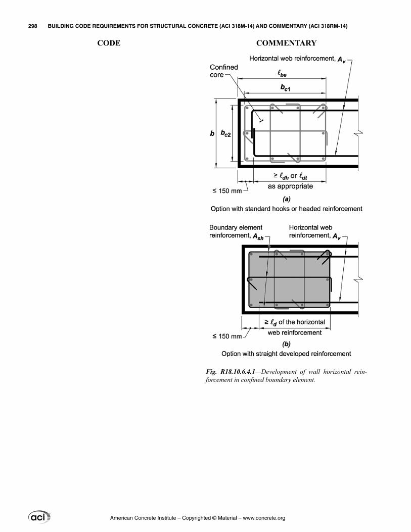
Fig. R18.10.6.4.1—Development of wall horizontal rein-forcement in confined boundary element.
American Concrete Institute – Copyrighted © Material – www.concrete.org
298 BUILDING CODE REQUIREMENTS FOR STRUCTURAL CONCRETE (ACI 318M-14) AND COMMENTARY (ACI 318RM-14)
CODE COMMENTARY
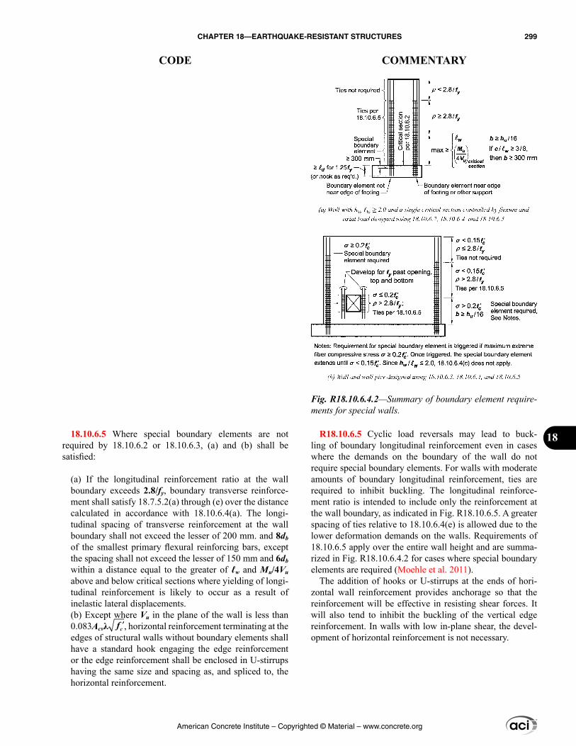
R18.10.6.5 Cyclic load reversals may lead to buck-ling of boundary longitudinal reinforcement even in cases where the demands on the boundary of the wall do not require special boundary elements. For walls with moderate amounts of boundary longitudinal reinforcement, ties are required to inhibit buckling. The longitudinal reinforce-ment ratio is intended to include only the reinforcement at the wall boundary, as indicated in Fig. R18.10.6.5. A greater spacing of ties relative to 18.10.6.4(e) is allowed due to the lower deformation demands on the walls. Requirements of 18.10.6.5 apply over the entire wall height and are summa-rized in Fig. R18.10.6.4.2 for cases where special boundary elements are required (Moehle et al. 2011).
The addition of hooks or U-stirrups at the ends of hori-zontal wall reinforcement provides anchorage so that the reinforcement will be effective in resisting shear forces. It will also tend to inhibit the buckling of the vertical edge reinforcement. In walls with low in-plane shear, the devel-opment of horizontal reinforcement is not necessary.
18.10.6.5 Where special boundary elements are not required by 18.10.6.2 or 18.10.6.3, (a) and (b) shall be satisfied:
(a) If the longitudinal reinforcement ratio at the wall boundary exceeds 2.8/fy, boundary transverse reinforce-ment shall satisfy 18.7.5.2(a) through (e) over the distance calculated in accordance with 18.10.6.4(a). The longi-tudinal spacing of transverse reinforcement at the wall boundary shall not exceed the lesser of 200 mm. and 8db of the smallest primary flexural reinforcing bars, except the spacing shall not exceed the lesser of 150 mm and 6db within a distance equal to the greater of ℓw and Mu/4Vu above and below critical sections where yielding of longi-tudinal reinforcement is likely to occur as a result of inelastic lateral displacements.(b) Except where Vu in the plane of the wall is less than 0.083Acvλ ′fc , horizontal reinforcement terminating at the edges of structural walls without boundary elements shall have a standard hook engaging the edge reinforcement or the edge reinforcement shall be enclosed in U-stirrups having the same size and spacing as, and spliced to, the horizontal reinforcement.
Fig. R18.10.6.4.2—Summary of boundary element require-ments for special walls.
American Concrete Institute – Copyrighted © Material – www.concrete.org
CHAPTER 18—EARTHQUAKE-RESISTANT STRUCTURES 299
CODE COMMENTARY
18
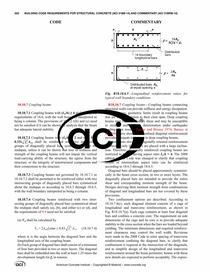
18.10.7 Coupling beams
18.10.7.1 Coupling beams with (ℓn/h) ≥ 4 shall satisfy the requirements of 18.6, with the wall boundary interpreted as being a column. The provisions of 18.6.2.1(b) and (c) need not be satisfied if it can be shown by analysis that the beam has adequate lateral stability.
18.10.7.2 Coupling beams with (ℓn/h) < 2 and with Vu ≥ 0.33λ ′fc Acw shall be reinforced with two intersecting groups of diagonally placed bars symmetrical about the midspan, unless it can be shown that loss of stiffness and strength of the coupling beams will not impair the vertical load-carrying ability of the structure, the egress from the structure, or the integrity of nonstructural components and their connections to the structure.
18.10.7.3 Coupling beams not governed by 18.10.7.1 or 18.10.7.2 shall be permitted to be reinforced either with two intersecting groups of diagonally placed bars symmetrical about the midspan or according to 18.6.3 through 18.6.5, with the wall boundary interpreted as being a column.
18.10.7.4 Coupling beams reinforced with two inter-secting groups of diagonally placed bars symmetrical about the midspan shall satisfy (a), (b), and either (c) or (d), and the requirements of 9.9 need not be satisfied:
(a) Vn shall be calculated by
Vn = 2Avd fysinα ≤ 0.83 cf ′ Acw (18.10.7.4)
where α is the angle between the diagonal bars and the longitudinal axis of the coupling beam.(b) Each group of diagonal bars shall consist of a minimum of four bars provided in two or more layers. The diagonal bars shall be embedded into the wall at least 1.25 times the development length for fy in tension.
R18.10.7 Coupling beams—Coupling beams connecting structural walls can provide stiffness and energy dissipation. In many cases, geometric limits result in coupling beams that are deep in relation to their clear span. Deep coupling beams may be controlled by shear and may be susceptible to strength and stiffness deterioration under earthquake loading. Test results (Paulay and Binney 1974; Barney et al. 1980) have shown that confined diagonal reinforcement provides adequate resistance in deep coupling beams.
Experiments show that diagonally oriented reinforcement is effective only if the bars are placed with a large inclina-tion. Therefore, diagonally reinforced coupling beams are restricted to beams having aspect ratio ℓn/h < 4. The 2008 edition of this Code was changed to clarify that coupling beams of intermediate aspect ratio can be reinforced according to 18.6.3 through 18.6.5.
Diagonal bars should be placed approximately symmetri-cally in the beam cross section, in two or more layers. The diagonally placed bars are intended to provide the entire shear and corresponding moment strength of the beam. Designs deriving their moment strength from combinations of diagonal and longitudinal bars are not covered by these provisions.
Two confinement options are described. According to 18.10.7.4(c), each diagonal element consists of a cage of longitudinal and transverse reinforcement, as shown in Fig. R18.10.7(a). Each cage contains at least four diagonal bars and confines a concrete core. The requirement on side dimensions of the cage and its core is to provide adequate stability to the cross section when the bars are loaded beyond yielding. The minimum dimensions and required reinforce-ment clearances may control the wall width. Revisions were made in the 2008 Code to relax spacing of transverse reinforcement confining the diagonal bars, to clarify that confinement is required at the intersection of the diagonals, and to simplify design of the longitudinal and transverse reinforcement around the beam perimeter; beams with these new details are expected to perform acceptably. The expres-
Fig. R18.10.6.5—Longitudinal reinforcement ratios for typical wall boundary conditions.
American Concrete Institute – Copyrighted © Material – www.concrete.org
300 BUILDING CODE REQUIREMENTS FOR STRUCTURAL CONCRETE (ACI 318M-14) AND COMMENTARY (ACI 318RM-14)
CODE COMMENTARY
(c) Each group of diagonal bars shall be enclosed by recti-linear transverse reinforcement having out-to-out dimen-sions of at least bw/2 in the direction parallel to bw and bw/5 along the other sides, where bw is the web width of the coupling beam. The transverse reinforcement shall be in accordance with 18.7.5.2(a) through (e), with Ash not less than the greater of (i) and (ii):
(i) 0.09 cc
yt
sbff
′
(ii) 0.3 1gc
ch y
c
t
Asb
ff
A
− ′
For the purpose of calculating Ag, the concrete cover in 20.6.1 shall be assumed on all four sides of each group of diagonal bars. The transverse reinforcement shall have spacing measured parallel to the diagonal bars satisfying 18.7.5.3(c) and not exceeding 6db of the smallest diag-onal bars, and shall have spacing of crossties or legs of hoops measured perpendicular to the diagonal bars not exceeding 350 mm. The transverse reinforcement shall continue through the intersection of the diagonal bars. At the intersection, it is permitted to modify the arrangement of the transverse reinforcement provided the spacing and volume ratio requirements are satisfied. Additional longi-tudinal and transverse reinforcement shall be distributed around the beam perimeter with total area in each direc-tion of at least 0.002bws and spacing not exceeding 300 mm.(d) Transverse reinforcement shall be provided for the entire beam cross section in accordance with 18.7.5.2(a) through (e) with Ash not less than the greater of (i) and (ii):
(i) 0.09 cc
yt
sbff
′
(ii) 0.3 1gc
ch y
c
t
Asb
ff
A
− ′
Longitudinal spacing of transverse reinforcement shall not exceed the lesser of 150 mm and 6db of the smallest diagonal bars. Spacing of crossties or legs of hoops both vertically and horizontally in the plane of the beam cross section shall not exceed 200 mm. Each crosstie and each hoop leg shall engage a longitudinal bar of equal or greater diameter. It shall be permitted to configure hoops as speci-fied in 18.6.4.3.
sions for transverse reinforcement Ash are based on ensuring compression capacity of an equivalent column section is maintained after spalling of cover concrete.
Section 18.10.7.4(d) describes a second option for confinement of the diagonals introduced in the 2008 Code (refer to Fig. R18.10.7(b)). This second option is to confine the entire beam cross section instead of confining the indi-vidual diagonals. This option can considerably simplify field placement of hoops, which can otherwise be especially chal-lenging where diagonal bars intersect each other or enter the wall boundary.
For coupling beams not used as part of the lateral-force-resisting system, the requirements for diagonal reinforce-ment may be waived.
Test results (Barney et al. 1980) demonstrate that beams reinforced as described in 18.10.7 have adequate ductility at shear forces exceeding 0.83 ′fc bwd. Consequently, the use of a limit of 0.83 ′fc Acw provides an acceptable upper limit.
American Concrete Institute – Copyrighted © Material – www.concrete.org
CHAPTER 18—EARTHQUAKE-RESISTANT STRUCTURES 301
CODE COMMENTARY
18
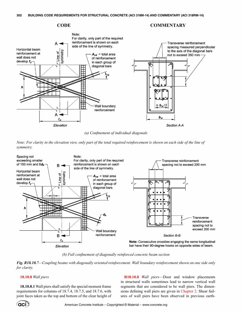
18.10.8 Wall piers
18.10.8.1 Wall piers shall satisfy the special moment frame requirements for columns of 18.7.4, 18.7.5, and 18.7.6, with joint faces taken as the top and bottom of the clear height of
(a) Confinement of individual diagonals
Note: For clarity in the elevation view, only part of the total required reinforcement is shown on each side of the line of symmetry.
(b) Full confinement of diagonally reinforced concrete beam section
Fig. R18.10.7—Coupling beams with diagonally oriented reinforcement. Wall boundary reinforcement shown on one side only for clarity.
R18.10.8 Wall piers—Door and window placements in structural walls sometimes lead to narrow vertical wall segments that are considered to be wall piers. The dimen-sions defining wall piers are given in Chapter 2. Shear fail-ures of wall piers have been observed in previous earth-
American Concrete Institute – Copyrighted © Material – www.concrete.org
302 BUILDING CODE REQUIREMENTS FOR STRUCTURAL CONCRETE (ACI 318M-14) AND COMMENTARY (ACI 318RM-14)
CODE COMMENTARY
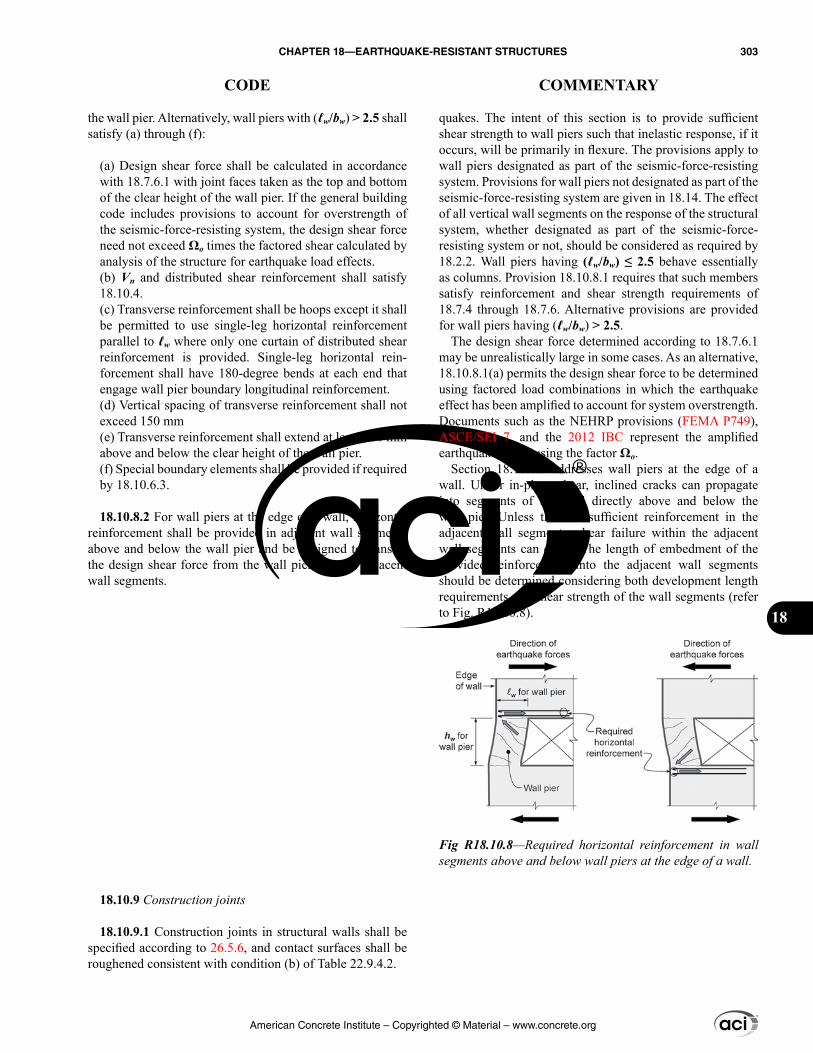
quakes. The intent of this section is to provide sufficient shear strength to wall piers such that inelastic response, if it occurs, will be primarily in flexure. The provisions apply to wall piers designated as part of the seismic-force-resisting system. Provisions for wall piers not designated as part of the seismic-force-resisting system are given in 18.14. The effect of all vertical wall segments on the response of the structural system, whether designated as part of the seismic-force-resisting system or not, should be considered as required by 18.2.2. Wall piers having (ℓw/bw) ≤ 2.5 behave essentially as columns. Provision 18.10.8.1 requires that such members satisfy reinforcement and shear strength requirements of 18.7.4 through 18.7.6. Alternative provisions are provided for wall piers having (ℓw/bw) > 2.5.
The design shear force determined according to 18.7.6.1 may be unrealistically large in some cases. As an alternative, 18.10.8.1(a) permits the design shear force to be determined using factored load combinations in which the earthquake effect has been amplified to account for system overstrength. Documents such as the NEHRP provisions (FEMA P749), ASCE/SEI 7, and the 2012 IBC represent the amplified earthquake effect using the factor Ωo.
Section 18.10.8.2 addresses wall piers at the edge of a wall. Under in-plane shear, inclined cracks can propagate into segments of the wall directly above and below the wall pier. Unless there is sufficient reinforcement in the adjacent wall segments, shear failure within the adjacent wall segments can occur. The length of embedment of the provided reinforcement into the adjacent wall segments should be determined considering both development length requirements and shear strength of the wall segments (refer to Fig. R18.10.8).
the wall pier. Alternatively, wall piers with (ℓw/bw) > 2.5 shall satisfy (a) through (f):
(a) Design shear force shall be calculated in accordance with 18.7.6.1 with joint faces taken as the top and bottom of the clear height of the wall pier. If the general building code includes provisions to account for overstrength of the seismic-force-resisting system, the design shear force need not exceed Ωo times the factored shear calculated by analysis of the structure for earthquake load effects.(b) Vn and distributed shear reinforcement shall satisfy 18.10.4.(c) Transverse reinforcement shall be hoops except it shall be permitted to use single-leg horizontal reinforcement parallel to ℓw where only one curtain of distributed shear reinforcement is provided. Single-leg horizontal rein-forcement shall have 180-degree bends at each end that engage wall pier boundary longitudinal reinforcement.(d) Vertical spacing of transverse reinforcement shall not exceed 150 mm(e) Transverse reinforcement shall extend at least 300 mm above and below the clear height of the wall pier.(f) Special boundary elements shall be provided if required by 18.10.6.3.
18.10.8.2 For wall piers at the edge of a wall, horizontal reinforcement shall be provided in adjacent wall segments above and below the wall pier and be designed to transfer the design shear force from the wall pier into the adjacent wall segments.
18.10.9 Construction joints
18.10.9.1 Construction joints in structural walls shall be specified according to 26.5.6, and contact surfaces shall be roughened consistent with condition (b) of Table 22.9.4.2.
Fig R18.10.8—Required horizontal reinforcement in wall segments above and below wall piers at the edge of a wall.
American Concrete Institute – Copyrighted © Material – www.concrete.org
CHAPTER 18—EARTHQUAKE-RESISTANT STRUCTURES 303
CODE COMMENTARY
18
R18.11—Special structural walls constructed using precast concrete
R18.11.2 General
R18.11.2.2 Experimental and analytical studies (Priestley et al. 1999; Perez et al. 2003; Restrepo 2002) have demon-strated that some types of precast structural walls post-tensioned with unbonded tendons, and not satisfying the prescriptive requirements of Chapter 18, provide satisfactory seismic performance characteristics. ACI ITG-5.1 defines a protocol for establishing a design procedure, validated by analysis and laboratory tests, for such walls, with or without coupling beams.
ACI ITG-5.2 defines design requirements for one type of special structural wall constructed using precast concrete and unbonded post-tensioning tendons, and validated for use in accordance with 18.11.2.2.
R18.12—Diaphragms and trusses R18.12.1 Scope—Diaphragms as used in building
construction are structural elements (such as a floor or roof) that provide some or all of the following functions:
(a) Support for building elements (such as walls, parti-tions, and cladding) resisting horizontal forces but not acting as part of the seismic-force-resisting system(b) Transfer of lateral forces from the point of applica-tion to the vertical elements of the seismic-force-resisting system(c) Connection of various components of the vertical seismic-force-resisting system with appropriate strength, stiffness, and ductility so the building responds as intended in the design (Wyllie 1987).
R18.12.2 Design forces
R18.12.2.1 In the general building code, earthquake design forces for floor and roof diaphragms typically are not calculated directly during the lateral-force analysis that provides story forces and story shears. Instead, diaphragm design forces at each level are calculated by a formula that amplifies the story forces recognizing dynamic effects
18.10.10 Discontinuous walls
18.10.10.1 Columns supporting discontinuous structural walls shall be reinforced in accordance with 18.7.5.6.
18.11—Special structural walls constructed using precast concrete
18.11.1 Scope
18.11.1.1 This section shall apply to special structural walls constructed using precast concrete forming part of the seismic-force-resisting system.
18.11.2 General
18.11.2.1 Special structural walls constructed using precast concrete shall satisfy 18.10 and 18.5.2.
18.11.2.2 Special structural walls constructed using precast concrete and unbonded post-tensioning tendons and not satisfying the requirements of 18.11.2.1 are permitted provided they satisfy the requirements of ACI ITG-5.1.
18.12—Diaphragms and trusses 18.12.1 Scope
18.12.1.1 This section shall apply to diaphragms and collectors forming part of the seismic-force-resisting system in structures assigned to SDC D, E, or F.
18.12.1.2 Section 18.12.11 shall apply to structural trusses forming part of the seismic-force-resisting system in struc-tures assigned to SDC D, E, or F.
18.12.2 Design forces
18.12.2.1 The earthquake design forces for diaphragms shall be obtained from the general building code using the applicable provisions and load combinations.
American Concrete Institute – Copyrighted © Material – www.concrete.org
304 BUILDING CODE REQUIREMENTS FOR STRUCTURAL CONCRETE (ACI 318M-14) AND COMMENTARY (ACI 318RM-14)
CODE COMMENTARY
and includes minimum and maximum limits. These forces are used with the governing load combinations to design diaphragms for shear and moment.
For collector elements, the general building code in the United States specifies load combinations that amplify earthquake forces by a factor Ωo. The forces amplified by Ωo are also used for the local diaphragm shear forces resulting from the transfer of collector forces, and for local diaphragm flexural moments resulting from any eccentricity of collector forces. The specific requirements for earth-quake design forces for diaphragms and collectors depend on which edition of the general building code is used. The requirements may also vary according to the SDC.
For most concrete buildings subjected to inelastic earth-quake demands, it is desirable to limit inelastic behavior of floor and roof diaphragms under the imposed earth-quake forces and deformations. It is preferable for inelastic behavior to occur only in the intended locations of the vertical seismic-force-resisting system that are detailed for ductile response, such as in beam plastic hinges of special moment frames, or in flexural plastic hinges at the base of structural walls or in coupling beams. For buildings without long diaphragm spans between lateral-force-resisting elements, elastic diaphragm behavior is typically not diffi-cult to achieve. For buildings where diaphragms could reach their flexural or shear strength before yielding occurs in the vertical seismic-force-resisting system, designers should consider providing increased diaphragm strength.
R18.12.3 Seismic load path
R18.12.3.2 This provision applies to strut-like elements that occur around openings, diaphragm edges, or other discontinuities in diaphragms. Figure R18.12.3.2 shows an example. Such elements can be subjected to earthquake axial forces in combination with bending and shear from earthquake or gravity loads.
18.12.3 Seismic load path
18.12.3.1 All diaphragms and their connections shall be designed and detailed to provide for transfer of forces to collector elements and to the vertical elements of the seismic-force-resisting system.
18.12.3.2 Elements of a structural diaphragm system that are subjected primarily to axial forces and used to transfer diaphragm shear or flexural forces around openings or other discontinuities shall satisfy the requirements for collectors in 18.12.7.5 and 18.12.7.6.
American Concrete Institute – Copyrighted © Material – www.concrete.org
CHAPTER 18—EARTHQUAKE-RESISTANT STRUCTURES 305
CODE COMMENTARY
18
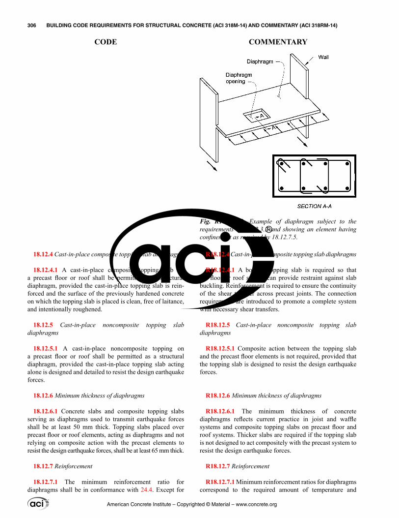
R18.12.4 Cast-in-place composite topping slab diaphragms
R18.12.4.1 A bonded topping slab is required so that the floor or roof system can provide restraint against slab buckling. Reinforcement is required to ensure the continuity of the shear transfer across precast joints. The connection requirements are introduced to promote a complete system with necessary shear transfers.
R18.12.5 Cast-in-place noncomposite topping slab diaphragms
R18.12.5.1 Composite action between the topping slab and the precast floor elements is not required, provided that the topping slab is designed to resist the design earthquake forces.
R18.12.6 Minimum thickness of diaphragms
R18.12.6.1 The minimum thickness of concrete diaphragms reflects current practice in joist and waffle systems and composite topping slabs on precast floor and roof systems. Thicker slabs are required if the topping slab is not designed to act compositely with the precast system to resist the design earthquake forces.
R18.12.7 Reinforcement
R18.12.7.1 Minimum reinforcement ratios for diaphragms correspond to the required amount of temperature and
18.12.4 Cast-in-place composite topping slab diaphragms
18.12.4.1 A cast-in-place composite topping slab on a precast floor or roof shall be permitted as a structural diaphragm, provided the cast-in-place topping slab is rein-forced and the surface of the previously hardened concrete on which the topping slab is placed is clean, free of laitance, and intentionally roughened.
18.12.5 Cast-in-place noncomposite topping slab diaphragms
18.12.5.1 A cast-in-place noncomposite topping on a precast floor or roof shall be permitted as a structural diaphragm, provided the cast-in-place topping slab acting alone is designed and detailed to resist the design earthquake forces.
18.12.6 Minimum thickness of diaphragms
18.12.6.1 Concrete slabs and composite topping slabs serving as diaphragms used to transmit earthquake forces shall be at least 50 mm thick. Topping slabs placed over precast floor or roof elements, acting as diaphragms and not relying on composite action with the precast elements to resist the design earthquake forces, shall be at least 65 mm thick.
18.12.7 Reinforcement
18.12.7.1 The minimum reinforcement ratio for diaphragms shall be in conformance with 24.4. Except for
Fig. R18.12.3.2—Example of diaphragm subject to the requirements of 18.12.3.2 and showing an element having confinement as required by 18.12.7.5.
American Concrete Institute – Copyrighted © Material – www.concrete.org
306 BUILDING CODE REQUIREMENTS FOR STRUCTURAL CONCRETE (ACI 318M-14) AND COMMENTARY (ACI 318RM-14)
CODE COMMENTARY
shrinkage reinforcement (refer to 24.4). The maximum spacing for reinforcement is intended to control the width of inclined cracks. Minimum average prestress requirements (refer to 24.4.4.1) are considered to be adequate to limit the crack widths in post-tensioned floor systems; therefore, the maximum spacing requirements do not apply to these systems.
The minimum spacing requirement for welded wire rein-forcement in topping slabs on precast floor systems is to avoid fracture of the distributed reinforcement during an earthquake. Cracks in the topping slab open immediately above the boundary between the flanges of adjacent precast members, and the wires crossing those cracks are restrained by the transverse wires (Wood et al. 2000). Therefore, all the deformation associated with cracking should be accommo-dated in a distance not greater than the spacing of the trans-verse wires. A minimum spacing of 250 mm for the trans-verse wires is required to reduce the likelihood of fracture of the wires crossing the critical cracks during a design earth-quake. The minimum spacing requirements do not apply to diaphragms reinforced with individual bars, because strains are distributed over a longer length.
R18.12.7.3 Bar development and lap splices are designed according to requirements of Chapter 25 for reinforcement in tension. Reductions in development or splice length for calculated stresses less than fy are not permitted, as indicated in 25.4.10.2.
R18.12.7.5 In documents such as the NEHRP Provi-sions (FEMA P750), ASCE/SEI 7, the 2012 IBC, and the Uniform Building Code (ICBO 1997), collector elements of diaphragms are designed for forces amplified by a factor Ωo to account for the overstrength in the vertical elements of the seismic-force-resisting systems. The amplification factor Ωo ranges between 2 and 3 for most concrete struc-tures, depending on the document selected and on the type of seismic-force-resisting system. In some documents, the factor can be calculated based on the maximum forces that can be developed by the elements of the vertical seismic-force-resisting system.
Compressive stress calculated for the factored forces on a linearly elastic model based on gross section of the structural diaphragm is used as an index value to determine whether confining reinforcement is required. A calculated compres-
post-tensioned slabs, reinforcement spacing each way in floor or roof systems shall not exceed 450 mm. Where welded wire reinforcement is used as the distributed reinforcement to resist shear in topping slabs placed over precast floor and roof elements, the wires parallel to the joints between the precast elements shall be spaced not less than 250 mm on center. Reinforcement provided for shear strength shall be continuous and shall be distributed uniformly across the shear plane.
18.12.7.2 Bonded tendons used as reinforcement to resist collector forces, diaphragm shear, or flexural tension shall be designed such that the stress due to design earthquake forces does not exceed 420 MPa. Precompression from unbonded tendons shall be permitted to resist diaphragm design forces if a seismic load path is provided.
18.12.7.3 All reinforcement used to resist collector forces, diaphragm shear, or flexural tension shall be developed or spliced for fy in tension.
18.12.7.4 Type 2 splices are required where mechanical splices are used to transfer forces between the diaphragm and the vertical elements of the seismic-force-resisting system.
18.12.7.5 Collector elements with compressive stresses exceeding 0.2fc′ at any section shall have transverse rein-forcement satisfying 18.7.5.2(a) through (e) and 18.7.5.3, except the spacing limit of 18.7.5.3(a) shall be one-third of the least dimension of the collector. The amount of transverse reinforcement shall be in accordance with Table 18.12.7.5. The specified transverse reinforcement is permitted to be discontinued at a section where the calculated compressive stress is less than 0.15fc′.
If design forces have been amplified to account for the overstrength of the vertical elements of the seismic-force-resisting system, the limit of 0.2fc′ shall be increased to 0.5fc′, and the limit of 0.15fc′ shall be increased to 0.4fc′.
American Concrete Institute – Copyrighted © Material – www.concrete.org
CHAPTER 18—EARTHQUAKE-RESISTANT STRUCTURES 307
CODE COMMENTARY
18
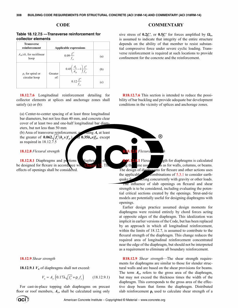
sive stress of 0.2fc′, or 0.5fc′ for forces amplified by Ωo, is assumed to indicate that integrity of the entire structure depends on the ability of that member to resist substan-tial compressive force under severe cyclic loading. Trans-verse reinforcement is required at such locations to provide confinement for the concrete and the reinforcement.
R18.12.7.6 This section is intended to reduce the possi-bility of bar buckling and provide adequate bar development conditions in the vicinity of splices and anchorage zones.
R18.12.8 Flexural strength
R18.12.8.1 Flexural strength for diaphragms is calculated using the same assumptions as for walls, columns, or beams. The design of diaphragms for flexure and other actions uses the applicable load combinations of 5.3.1 to consider earth-quake forces acting concurrently with gravity or other loads.
The influence of slab openings on flexural and shear strength is to be considered, including evaluating the poten-tial critical sections created by the openings. Strut-and-tie models are potentially useful for designing diaphragms with openings.
Earlier design practice assumed design moments for diaphragms were resisted entirely by chord forces acting at opposite edges of the diaphragm. This idealization was implicit in earlier versions of the Code, but has been replaced by an approach in which all longitudinal reinforcement, within the limits of 18.12.7, is assumed to contribute to the flexural strength of the diaphragm. This change reduces the required area of longitudinal reinforcement concentrated near the edge of the diaphragm, but should not be interpreted as a requirement to eliminate all boundary reinforcement.
R18.12.9 Shear strength—The shear strength require-ments for diaphragms are similar to those for slender struc-tural walls and are based on the shear provisions for beams. The term Acv refers to the gross area of the diaphragm, but may not exceed the thickness times the width of the diaphragm. This corresponds to the gross area of the effec-tive deep beam that forms the diaphragm. Distributed slab reinforcement ρt used to calculate shear strength of a
Table 18.12.7.5 —Transverse reinforcement for collector elements
Transverse reinforcement Applicable expressions
Ash/sbc for rectilinear hoop
0.09yt
cff
′(a)
ρs for spiral or circular hoop
Greater of:
0.45 1g
ch yt
cfAA f
′−
(b)
0.12yt
cff
′(c)
18.12.7.6 Longitudinal reinforcement detailing for collector elements at splices and anchorage zones shall satisfy (a) or (b):
(a) Center-to-center spacing of at least three longitudinal bar diameters, but not less than 40 mm, and concrete clear cover of at least two and one-half longitudinal bar diam-eters, but not less than 50 mm(b) Area of transverse reinforcement, providing Av at least the greater of ( / )′0.062 c w ytf b s f and 0.35bws/fyt, except as required in 18.12.7.5
18.12.8 Flexural strength
18.12.8.1 Diaphragms and portions of diaphragms shall be designed for flexure in accordance with Chapter 12. The effects of openings shall be considered.
18.12.9 Shear strength
18.12.9.1 Vn of diaphragms shall not exceed:
( )0.17= λ + ρ′n cv c t yV A f f (18.12.9.1)
For cast-in-place topping slab diaphragms on precast floor or roof members, Acv shall be calculated using only
American Concrete Institute – Copyrighted © Material – www.concrete.org
308 BUILDING CODE REQUIREMENTS FOR STRUCTURAL CONCRETE (ACI 318M-14) AND COMMENTARY (ACI 318RM-14)
CODE COMMENTARY
the thickness of topping slab for noncomposite topping slab diaphragms and the combined thickness of cast-in-place and precast elements for composite topping slab diaphragms. For composite topping slab diaphragms, the value of fc′ used to calculate Vn shall not exceed the lesser of fc′ for the precast members and fc′ for the topping slab.
18.12.9.2 Vn of diaphragms shall not exceed 0.66Acv ′fc .
18.12.9.3 Above joints between precast elements in noncomposite and composite cast-in-place topping slab diaphragms, Vn shall not exceed:
Vn = Avf fyμ (18.12.9.3)
where Avf is the total area of shear friction reinforcement within the topping slab, including both distributed and boundary reinforcement, that is oriented perpendicular to joints in the precast system and coefficient of friction, μ, is 1.0λ, where λ is given in 19.2.4. At least one-half of Avf shall be uniformly distributed along the length of the poten-tial shear plane. The area of distributed reinforcement in the topping slab shall satisfy 24.4.3.2 in each direction.
18.12.9.4 Above joints between precast elements in noncomposite and composite cast-in-place topping slab diaphragms, Vn shall not exceed the limits in 22.9.4.4, where Ac is calculated using only the thickness of the topping slab.
18.12.10 Construction joints
18.12.10.1 Construction joints in diaphragms shall be specified according to 26.5.6, and contact surfaces shall be roughened consistent with condition (b) of Table 22.9.4.2.
18.12.11 Structural trusses
18.12.11.1 Structural truss elements with compressive stresses exceeding 0.2fc′ at any section shall have trans-verse reinforcement, in accordance with 18.7.5.2, 18.7.5.3, 18.7.5.7, and Table 18.12.11.1, over the length of the element.
diaphragm in Eq. (18.12.9.1) is positioned perpendicular to the diaphragm flexural reinforcement. Provision 18.12.9.2 limits the maximum shear strength of the diaphragm.
In addition to satisfying 18.12.9.1 and 18.12.9.2, cast-in-place topping slab diaphragms must also satisfy 18.12.9.3 and 18.12.9.4. Cast-in-place topping slabs on a precast floor or roof system tend to have shrinkage cracks that are aligned with the joints between adjacent precast members. There-fore, the additional shear strength requirements for topping slab diaphragms in 18.12.9.3 are based on a shear friction model (Wood et al. 2000), and the assumed crack plane corresponds to joints in the precast system along the direc-tion of the applied shear, as shown in Fig. R22.9.4.3. The coefficient of friction, μ, in the shear friction model is taken equal to 1.0 for normalweight concrete due to the presence of these shrinkage cracks.
Both distributed and boundary reinforcement in the topping slab may be considered as shear friction reinforce-ment Avf. Boundary reinforcement within the diaphragm was called chord reinforcement in ACI 318 before 2008. Although the boundary reinforcement also resists forces due to moment and axial force in the diaphragm, the reduction in the shear friction resistance in the tension zone is offset by the increase in shear friction resistance in the compres-sion zone. Therefore, the area of boundary reinforcement used to resist shear friction need not be added to the area of boundary reinforcement used to resist moment and axial force. The distributed topping slab reinforcement must contribute at least one-half of the nominal shear strength. It is assumed that connections between the precast elements do not contribute to the shear strength of the topping slab diaphragm.
Provision 18.12.9.4 limits the maximum shear that may be transmitted by shear friction within a topping slab diaphragm.
R18.12.11 Structural trusses
R18.12.11.1 The expressions for transverse reinforcement Ash are based on ensuring compression capacity of an equiv-alent column section is maintained after spalling of cover concrete.
American Concrete Institute – Copyrighted © Material – www.concrete.org
CHAPTER 18—EARTHQUAKE-RESISTANT STRUCTURES 309
CODE COMMENTARY
18
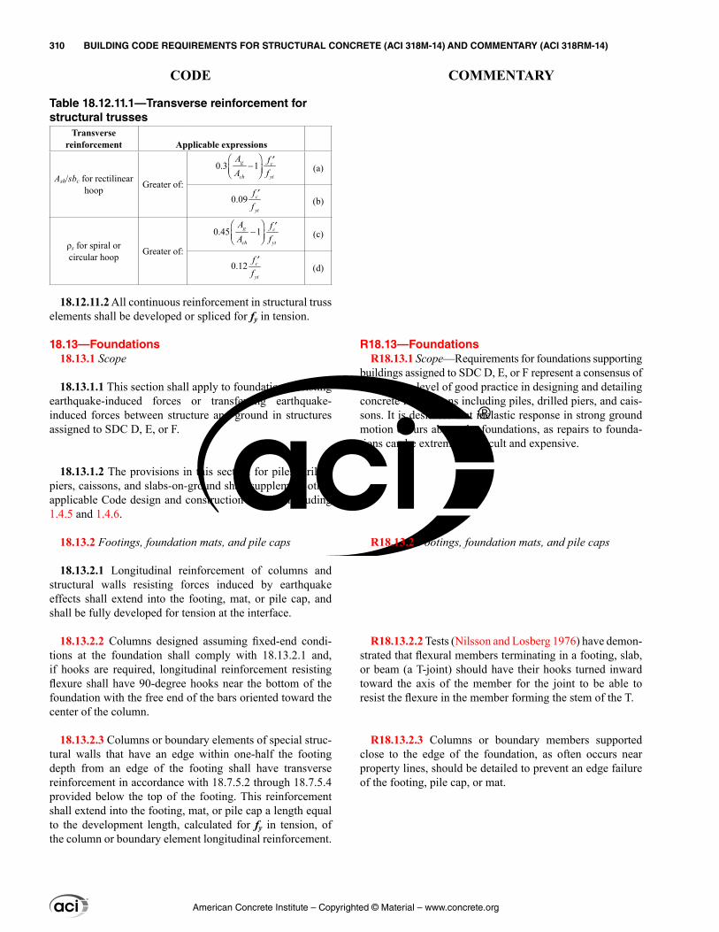
R18.13—Foundations R18.13.1 Scope—Requirements for foundations supporting
buildings assigned to SDC D, E, or F represent a consensus of a minimum level of good practice in designing and detailing concrete foundations including piles, drilled piers, and cais-sons. It is desirable that inelastic response in strong ground motion occurs above the foundations, as repairs to founda-tions can be extremely difficult and expensive.
R18.13.2 Footings, foundation mats, and pile caps
R18.13.2.2 Tests (Nilsson and Losberg 1976) have demon-strated that flexural members terminating in a footing, slab, or beam (a T-joint) should have their hooks turned inward toward the axis of the member for the joint to be able to resist the flexure in the member forming the stem of the T.
R18.13.2.3 Columns or boundary members supported close to the edge of the foundation, as often occurs near property lines, should be detailed to prevent an edge failure of the footing, pile cap, or mat.
Table 18.12.11.1—Transverse reinforcement for structural trusses
Transverse reinforcement Applicable expressions
Ash/sbc for rectilinear hoop Greater of:
0.3 1g c
ch yt
Aff
A
− ′
(a)
0.09yt
cff
′(b)
ρs for spiral or circular hoop Greater of:
0.45 1g
ch yt
cfAA f
′− (c)
0.12yt
cff
′(d)
18.12.11.2 All continuous reinforcement in structural truss elements shall be developed or spliced for fy in tension.
18.13—Foundations 18.13.1 Scope
18.13.1.1 This section shall apply to foundations resisting earthquake-induced forces or transferring earthquake-induced forces between structure and ground in structures assigned to SDC D, E, or F.
18.13.1.2 The provisions in this section for piles, drilled piers, caissons, and slabs-on-ground shall supplement other applicable Code design and construction criteria, including 1.4.5 and 1.4.6.
18.13.2 Footings, foundation mats, and pile caps
18.13.2.1 Longitudinal reinforcement of columns and structural walls resisting forces induced by earthquake effects shall extend into the footing, mat, or pile cap, and shall be fully developed for tension at the interface.
18.13.2.2 Columns designed assuming fixed-end condi-tions at the foundation shall comply with 18.13.2.1 and, if hooks are required, longitudinal reinforcement resisting flexure shall have 90-degree hooks near the bottom of the foundation with the free end of the bars oriented toward the center of the column.
18.13.2.3 Columns or boundary elements of special struc-tural walls that have an edge within one-half the footing depth from an edge of the footing shall have transverse reinforcement in accordance with 18.7.5.2 through 18.7.5.4 provided below the top of the footing. This reinforcement shall extend into the footing, mat, or pile cap a length equal to the development length, calculated for fy in tension, of the column or boundary element longitudinal reinforcement.
American Concrete Institute – Copyrighted © Material – www.concrete.org
310 BUILDING CODE REQUIREMENTS FOR STRUCTURAL CONCRETE (ACI 318M-14) AND COMMENTARY (ACI 318RM-14)
CODE COMMENTARY
R18.13.2.4 The purpose of this section is to emphasize that top reinforcement may be required, in addition to other required reinforcement.
R18.13.2.5 Foundation or basement walls should be rein-forced in buildings assigned to SDC D, E, or F.
R18.13.3 Grade beams and slabs-on-ground—For earth-quake conditions, slabs-on-ground (soil-supported slabs) are often part of the lateral-force-resisting system and should be designed in accordance with this Code as well as other appropriate standards or guidelines (refer to 1.4.7).
R18.13.3.2 Grade beams between pile caps or footings can be separate beams beneath the slab-on-ground or can be a thickened portion of the slab-on-ground. The cross-sectional limitation and minimum tie requirements provide reasonable proportions.
R18.13.3.3 Grade beams resisting flexural stresses from column moments should have reinforcement details similar to the beams of the frame above the foundation.
R18.13.3.4 Slabs-on-ground often act as a diaphragm to tie the building together at the ground level and minimize the effects of out-of-phase ground motion that may occur over the footprint of the building. In these cases, the slab-on-ground should be adequately reinforced and detailed. The construction documents should clearly state that these slabs-on-ground are structural members so as to prohibit saw cutting of the slab.
R18.13.4 Piles, piers, and caissons—Adequate perfor-mance of piles and caissons for earthquake effects requires that these provisions be met in addition to other applicable standards or guidelines (refer to R1.4.5).
R18.13.4.1 A load path is necessary at pile caps to transfer tension forces from the reinforcing bars in the column or boundary member through the pile cap to the reinforcement of the pile or caisson.
R18.13.4.2 Grouted dowels in a blockout in the top of a precast concrete pile need to be developed, and testing is a practical means of demonstrating strength. Alternatively, reinforcing bars can be cast in the upper portion of the pile,
18.13.2.4 Where earthquake effects create uplift forces in boundary elements of special structural walls or columns, flexural reinforcement shall be provided in the top of the footing, mat, or pile cap to resist actions resulting from the factored load combinations, and shall be at least that required by 7.6.1 or 9.6.1.
18.13.2.5 Structural plain concrete in footings and base-ment walls shall be in accordance with 14.1.4.
18.13.3 Grade beams and slabs-on-ground
18.13.3.1 Grade beams designed to act as horizontal ties between pile caps or footings shall have continuous longitu-dinal reinforcement that shall be developed within or beyond the supported column or anchored within the pile cap or footing at all discontinuities.
18.13.3.2 Grade beams designed to act as horizontal ties between pile caps or footings shall be sized such that the smallest cross-sectional dimension shall be at least equal to the clear spacing between connected columns divided by 20, but need not exceed 450 mm. Closed ties shall be provided at a spacing not to exceed the lesser of one-half the smallest orthogonal cross-sectional dimension and 300 mm.
18.13.3.3 Grade beams and beams that are part of a mat foundation subjected to flexure from columns that are part of the seismic-force-resisting system shall be in accordance with 18.6.
18.13.3.4 Slabs-on-ground that resist earthquake forces from walls or columns that are part of the seismic-force-resisting system shall be designed as diaphragms in accor-dance with 18.12. The construction documents shall clearly indicate that the slab-on-ground is a structural diaphragm and part of the seismic-force-resisting system.
18.13.4 Piles, piers, and caissons
18.13.4.1 Piles, piers, or caissons resisting tension loads shall have continuous longitudinal reinforcement over the length resisting design tension forces. The longitudinal rein-forcement shall be detailed to transfer tension forces within the pile cap to supported structural members.
18.13.4.2 Where tension forces induced by earthquake effects are transferred between pile cap or mat foundation and precast pile by reinforcing bars grouted or post-installed in the top of the pile, the grouting system shall have been demonstrated by test to develop at least 1.25fy of the bar.
American Concrete Institute – Copyrighted © Material – www.concrete.org
CHAPTER 18—EARTHQUAKE-RESISTANT STRUCTURES 311
CODE COMMENTARY
18
exposed by chipping of concrete and mechanically spliced or welded to an extension.
R18.13.4.3 During earthquakes, piles can be subjected to extremely high flexural demands at points of discontinuity, especially just below the pile cap and near the base of a soft or loose soil deposit. The Code requirement for confinement reinforcement at the top of the pile is based on numerous failures observed at this location in earthquakes. Transverse reinforcement is required in this region to provide ductile performance. Possible inelastic action in the pile at abrupt changes in soil deposits should also be considered, such as changes from soft to firm or loose to dense soil layers. Where precast piles are to be used, the potential for the pile tip to be driven to an elevation different than that specified in the construction documents needs to be considered when detailing the pile. If the pile reaches refusal at a shallower depth, a longer length of pile will need to be cut off. If this possibility is not foreseen, the length of transverse reinforce-ment required by this provision may not be available after the excess pile length is cut off.
R18.13.4.6 Extensive structural damage has often been observed at the junction of batter piles and buildings. The pile cap and surrounding structure should be designed for the potentially large forces that can be developed in batter piles.
R18.14—Members not designated as part of the seismic-force-resisting system
This section applies only to structures assigned to SDC D, E, or F. For those SDCs, all structural members not designated as a part of the seismic-force-resisting system are required to be designed to support gravity loads while subjected to the design displacement. For concrete structures, the provisions of this section satisfy this requirement for columns, beams, slabs, and wall piers of the gravity system. Provision 18.14.2 defines the load and displacement combinations that must be considered.
Design displacement is defined in Chapter 2. Models used to determine design displacement of buildings should be chosen to produce results that conservatively bound the values expected during the design earthquake and should include, as appropriate, effects of concrete cracking, founda-tion flexibility, and deformation of floor and roof diaphragms.
18.13.4.3 Piles, piers, or caissons shall have transverse reinforcement in accordance with 18.7.5.2(a) through (e), 18.7.5.3, and 18.7.5.4 excluding requirements of (c) and (f) of Table 18.7.5.4 at locations (a) and (b):
(a) At the top of the member for at least five times the member cross-sectional dimension, and at least 1.8 m below the bottom of the pile cap(b) For the portion of piles in soil that is not capable of providing lateral support, or in air and water, along the entire unsupported length plus the length required in (a).
18.13.4.4 For precast concrete driven piles, the length of transverse reinforcement provided shall be sufficient to account for potential variations in the elevation of pile tips.
18.13.4.5 Concrete piles, piers, or caissons in foundations supporting one- and two-story stud bearing wall construc-tion are exempt from the transverse reinforcement require-ments of 18.13.4.3 and 18.13.4.4.
18.13.4.6 Pile caps incorporating batter piles shall be designed to resist the full compressive strength of the batter piles acting as short columns. The slenderness effects of batter piles shall be considered for the portion of the piles in soil that is not capable of providing lateral support, or in air or water.
18.14—Members not designated as part of the seismic-force-resisting system
18.14.1 Scope
18.14.1.1 This section shall apply to members not desig-nated as part of the seismic-force-resisting system in struc-tures assigned to SDC D, E, and F.
18.14.2 Design actions
18.14.2.1 Members not designated as part of the seismic-force-resisting system shall be evaluated for gravity load combinations of (1.2D + 1.0L + 0.2S) or 0.9D, whichever is critical, acting simultaneously with the design displacement δu. The load factor on the live load, L, shall be permitted to be reduced to 0.5 except for garages, areas occupied as places of public assembly, and all areas where L is greater than 4.8 kN/m2.
American Concrete Institute – Copyrighted © Material – www.concrete.org
312 BUILDING CODE REQUIREMENTS FOR STRUCTURAL CONCRETE (ACI 318M-14) AND COMMENTARY (ACI 318RM-14)
CODE COMMENTARY
The provisions of 18.14 are intended to enable ductile flexural yielding of columns, beams, slabs, and wall piers under the design displacement, by providing sufficient confinement and shear strength in elements that yield.
R18.14.3 Cast-in-place beams, columns, and joints
R18.14.3.1 Cast-in-place columns and beams are assumed to yield if the combined effects of factored gravity loads and design displacements exceed the strengths specified, or if the effects of design displacements are not calculated. Require-ments for transverse reinforcement and shear strength vary with member type and whether the member yields under the design displacement.
R18.14.4 Precast beams and columns
R18.14.4.1 Damage to some buildings with precast concrete gravity systems during the 1994 Northridge earth-quake was attributed to several factors addressed in this section. Columns should contain ties over their entire height, frame members not proportioned to resist earthquake forces should be tied together, and longer bearing lengths should be used to maintain integrity of the gravity system during ground motion. The 50 mm increase in bearing length is
18.14.3 Cast-in-place beams, columns, and joints
18.14.3.1 Cast-in-place beams and columns shall be detailed in accordance with 18.14.3.2 or 18.14.3.3 depending on the magnitude of moments and shears induced in those members when subjected to the design displacement δu. If effects of δu are not explicitly checked, the provisions of 18.14.3.3 shall be satisfied.
18.14.3.2 Where the induced moments and shears do not exceed the design moment and shear strength of the frame member, (a) through (c) shall be satisfied:
(a) Beams shall satisfy 18.6.3.1. Transverse reinforce-ment shall be provided throughout the length of the beam at spacing not to exceed d/2. Where factored axial force exceeds Ag fc′/10, transverse reinforcement shall be hoops satisfying 18.7.5.2 at spacing so, according to 18.14.3.2(b).(b) Columns shall satisfy 18.7.4.1, 18.7.5.2, and 18.7.6. The maximum longitudinal spacing of hoops shall be so for the full column length. Spacing so shall not exceed the lesser of six diameters of the smallest longitudinal bar enclosed and 150 mm(c) Columns with factored gravity axial forces exceeding 0.35Po shall satisfy 18.14.3.2(b) and 18.7.5.7. The amount of transverse reinforcement provided shall be one-half of that required by 18.7.5.4 and spacing shall not exceed so for the full column length.
18.14.3.3 Where the induced moments or shears exceed ϕMn or ϕVn of the frame member, or if induced moments or shears are not calculated, (a) through (d) shall be satisfied:
(a) Materials, mechanical splices, and welded splices shall satisfy the requirements for special moment frames in 18.2.5 through 18.2.8.(b) Beams shall satisfy 18.14.3.2(a) and 18.6.5.(c) Columns shall satisfy 18.7.4, 18.7.5, and 18.7.6.(d) Joints shall satisfy 18.8.3.1.
18.14.4 Precast beams and columns
18.14.4.1 Precast concrete frame members assumed not to contribute to lateral resistance, including their connections, shall satisfy (a) through (d):
(a) Requirements of 18.14.3(b) Ties specified in 18.14.3.2(b) over the entire column height, including the depth of the beams
American Concrete Institute – Copyrighted © Material – www.concrete.org
CHAPTER 18—EARTHQUAKE-RESISTANT STRUCTURES 313
CODE COMMENTARY
18
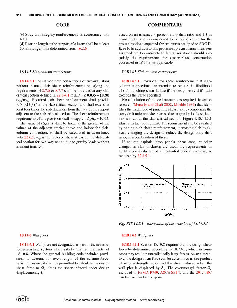
(c) Structural integrity reinforcement, in accordance with 4.10(d) Bearing length at the support of a beam shall be at least 50 mm longer than determined from 16.2.6
18.14.5 Slab-column connections
18.14.5.1 For slab-column connections of two-way slabs without beams, slab shear reinforcement satisfying the requirements of 8.7.6 or 8.7.7 shall be provided at any slab critical section defined in 22.6.4.1 if ∆x/hsx ≥ 0.035 – (1/20)(vug/ϕvc). Required slab shear reinforcement shall provide vs ≥ 0.29 ′fc at the slab critical section and shall extend at least four times the slab thickness from the face of the support adjacent to the slab critical section. The shear reinforcement requirements of this provision shall not apply if ∆x/hsx ≤ 0.005.
The value of (∆x/hsx) shall be taken as the greater of the values of the adjacent stories above and below the slab-column connection. vc shall be calculated in accordance with 22.6.5. vug is the factored shear stress on the slab crit-ical section for two-way action due to gravity loads without moment transfer.
18.14.6 Wall piers
18.14.6.1 Wall piers not designated as part of the seismic-force-resisting system shall satisfy the requirements of 18.10.8. Where the general building code includes provi-sions to account for overstrength of the seismic-force-resisting system, it shall be permitted to calculate the design shear force as Ωo times the shear induced under design displacements, δu.
based on an assumed 4 percent story drift ratio and 1.3 m beam depth, and is considered to be conservative for the ground motions expected for structures assigned to SDC D, E, or F. In addition to this provision, precast frame members assumed not to contribute to lateral resistance should also satisfy the requirements for cast-in-place construction addressed in 18.14.3, as applicable.
R18.14.5 Slab-column connections
R18.14.5.1 Provisions for shear reinforcement at slab-column connections are intended to reduce the likelihood of slab punching shear failure if the design story drift ratio exceeds the value specified.
No calculation of induced moments is required, based on research (Megally and Ghali 2002; Moehle 1996) that iden-tifies the likelihood of punching shear failure considering the story drift ratio and shear stress due to gravity loads without moment about the slab critical section. Figure R18.14.5.1 illustrates the requirement. The requirement can be satisfied by adding slab shear reinforcement, increasing slab thick-ness, changing the design to reduce the design story drift ratio, or a combination of these.
If column capitals, drop panels, shear caps, or other changes in slab thickness are used, the requirements of 18.14.5 are evaluated at all potential critical sections, as required by 22.6.5.1.
R18.14.6 Wall piers
R18.14.6.1 Section 18.10.8 requires that the design shear force be determined according to 18.7.6.1, which in some cases may result in unrealistically large forces. As an alterna-tive, the design shear force can be determined as the product of an overstrength factor and the shear induced when the wall pier is displaced by δu. The overstrength factor Ωo included in FEMA P749, ASCE/SEI 7, and the 2012 IBC can be used for this purpose.
Fig. R18.14.5.1—Illustration of the criterion of 18.14.5.1.
American Concrete Institute – Copyrighted © Material – www.concrete.org
314 BUILDING CODE REQUIREMENTS FOR STRUCTURAL CONCRETE (ACI 318M-14) AND COMMENTARY (ACI 318RM-14)
CODE COMMENTARY
CHAPTER 19—CONCRETE: DESIGN AND DURABILITY REQUIREMENTS
19.1—Scope19.1.1 This chapter shall apply to concrete, including:
(a) Properties to be used for design(b) Durability requirements
19.1.2 This chapter shall apply to durability requirements for grout used for bonded tendons in accordance with 19.4.
19.2—Concrete design properties 19.2.1 Specified compressive strength
19.2.1.1 The value of fc′ shall be specified in construction documents and shall be in accordance with (a) through (c):
(a) Limits in Table 19.2.1.1(b) Durability requirements in Table 19.3.2.1(c) Structural strength requirements
Table 19.2.1.1—Limits for fc′
Application ConcreteMinimumfc′, MPa
Maximum fc′, MPa
General Normalweight and lightweight 17 None
Special moment frames and special
structural walls
Normalweight 21 None
Lightweight 21 35[1]
[1]The limit is permitted to be exceeded where demonstrated by experimental evidence that members made with lightweight concrete provide strength and toughness equal to or exceeding those of comparable members made with normalweight concrete of the same strength.
19.2.1.2 The specified compressive strength shall be used for proportioning of concrete mixtures in 26.4.3 and for testing and acceptance of concrete in 26.12.3.
19.2.1.3 Unless otherwise specified, fc′ shall be based on 28-day tests. If other than 28 days, test age for fc′ shall be indicated in the construction documents.
19.2.2 Modulus of elasticity
19.2.2.1 Modulus of elasticity, Ec, for concrete shall be permitted to be calculated as (a) or (b):
(a) For values of wc between 1440 and 2560 kg/m3
Ec = wc1.50.043 ′fc (in MPa) (19.2.2.1.a)
(b) For normalweight concrete
Ec = 4700 ′fc (in MPa) (19.2.2.1.b)
R19—CONCRETE: DESIGN AND DURABILITY REQUIREMENTS
R19.2—Concrete design properties R19.2.1 Specified compressive strength—Requirements
for concrete mixtures are based on the philosophy that concrete should provide both adequate strength and dura-bility. The Code defines a minimum value of fc′ for struc-tural concrete. There is no limit on the maximum value of fc′ except as required by specific Code provisions.
Concrete mixtures proportioned in accordance with 26.4.3 should achieve an average compressive strength that exceeds the value of fc′ used in the structural design calculations. The amount by which the average strength of concrete exceeds fc′ is based on statistical concepts. When concrete is designed to achieve a strength level greater than fc′, it ensures that the concrete strength tests will have a high probability of meeting the strength acceptance criteria in 26.12.3. The durability requirements prescribed in Table 19.3.2.1 are to be satisfied in addition to meeting the minimum fc′ of 19.2.1. Under some circumstances, durability requirements may dictate a higher fc′ than that required for structural purposes.
For design of special moment frames and special struc-tural walls used to resist earthquake forces, the Code limits the maximum fc′ of lightweight concrete to 35 MPa. This limit is imposed primarily because of a paucity of experi-mental and field data on the behavior of members made with lightweight concrete subjected to displacement reversals in the nonlinear range.
The Code also limits fc′ for design of anchors to concrete. The requirements are in 17.2.7.
R19.2.2 Modulus of elasticity
R19.2.2.1 Studies leading to the expression for modulus of elasticity of concrete are summarized in Pauw (1960), where Ec is defined as the slope of the line drawn from a stress of zero to a compressive stress of 0.45fc′. The modulus of elasticity for concrete is sensitive to the modulus of elas-ticity of aggregate and mixture proportions of the concrete. Measured elastic modulus values can range from 80 to 120 percent of calculated values. ASTM C469M provides a test method for determining the modulus of elasticity for concrete in compression.
American Concrete Institute – Copyrighted © Material – www.concrete.org
CHAPTER 19—CONCRETE: DESIGN AND DURABILITY REQUIREMENTS 315
CODE COMMENTARY
19
R19.2.4 Lightweight concrete—The modification factor λ is used to account for the lower tensile-to-compressive strength ratio of lightweight concrete compared with normal-weight concrete. For design using lightweight concrete, shear strength, friction properties, splitting resistance, bond between concrete and reinforcement, and development length requirements are not taken as equivalent to normal-weight concrete of the same compressive strength.
Typically, the designer will not know the blends of aggre-gate necessary to achieve the target design strength and density required for a project. In most cases, local concrete and aggregate suppliers have standard lightweight concrete mixtures and can provide the volumetric fractions of light-weight and normalweight aggregates necessary to achieve the target values. These volumetric fractions can be used to determine the value of λ, or in the absence of such data, it is permissible to use the lower-bound value of λ for the type of lightweight concrete specified.
Two alternative procedures are provided to determine λ. The first alternative is based on the assumption that, for equivalent compressive strength levels, the tensile strength of lightweight concrete is a fixed fraction of the tensile strength of normalweight concrete (Ivey and Buth 1967). The multipliers used for λ are based on data from tests on concrete made with many types of structural lightweight aggregate.
The second alternative procedure to determine λ is based on laboratory tests of lightweight concrete with aggregate source and compressive strength representative of that to be used in the Work. The laboratory tests performed in accor-dance with ASTM C330M provide a measured average split-ting tensile strength fct and a measured average compressive strength fcm for the lightweight concrete. The value of λ is determined using Eq. (19.2.4.3), which is based on the assumption that the average splitting tensile strength of normalweight concrete is equal to 0.56 fcm (Ivey and Buth 1967; Hanson 1961).
R19.3—Concrete durability requirements Durability of concrete is impacted by the resistance of the
concrete to fluid penetration. This is primarily affected by w/cm and the composition of cementitious materials used in concrete. For a given w/cm, the use of fly ash, slag cement,
19.2.3 Modulus of rupture
19.2.3.1 Modulus of rupture, fr, for concrete shall be calculated by:
fr = 0.62λ ′fc (19.2.3.1)
where the value of λ is in accordance with 19.2.4.
19.2.4 Lightweight concrete
19.2.4.1 To account for the properties of lightweight concrete, a modification factor λ is used as a multiplier of
′fc in all applicable provisions of this Code.
19.2.4.2 The value of λ shall be based on the composition of the aggregate in the concrete mixture in accordance with Table 19.2.4.2 or as permitted in 19.2.4.3.
Table 19.2.4.2—Modification factor λConcrete Composition of aggregates λ
All-lightweight Fine: ASTM C330MCoarse: ASTM C330M 0.75
Lightweight, fine blend
Fine: Combination of ASTM C330M and C33M
Coarse: ASTM C330M0.75 to 0.85[1]
Sand-lightweight Fine: ASTM C33MCoarse: ASTM C330M 0.85
Sand-lightweight, coarse blend
Fine: ASTM C33MCoarse: Combination of ASTM
C330M and C33M0.85 to 1[2]
Normalweight Fine: ASTM C33MCoarse: ASTM C33M 1
[1]Linear interpolation from 0.75 to 0.85 is permitted based on the absolute volume of normalweight fine aggregate as a fraction of the total absolute volume of fine aggregate.[2]Linear interpolation from 0.85 to 1 is permitted based on the absolute volume of normalweight coarse aggregate as a fraction of the total absolute volume of coarse aggregate.
19.2.4.3 If the measured average splitting tensile strength of lightweight concrete, fct, is used to calculate λ, laboratory tests shall be conducted in accordance with ASTM C330M to establish the value of fct and the corresponding value of fcm and λ shall be calculated by:
1.00.56
λ = ≤ct
cm
ff
(19.2.4.3)
The concrete mixture tested in order to calculate λ shall be representative of that to be used in the Work.
19.3—Concrete durability requirements
American Concrete Institute – Copyrighted © Material – www.concrete.org
316 BUILDING CODE REQUIREMENTS FOR STRUCTURAL CONCRETE (ACI 318M-14) AND COMMENTARY (ACI 318RM-14)
CODE COMMENTARY
silica fume, or a combination of these materials will typically increase the resistance of concrete to fluid penetration and thus improve concrete durability. The Code places emphasis on w/cm for achieving low permeability to meet durability requirements. ASTM C1202 can be used to provide an indi-cation of concrete’s resistance to fluid penetration.
Because it is difficult to verify accurately the w/cm of concrete, the selected value of fc′ should be consistent with the maximum w/cm required for durability. Selection of an fc′ that is consistent with the maximum permitted w/cm required for durability will permit results of strength tests to be used as a surrogate for w/cm, and thus help ensure that the maximum w/cm is not exceeded in the field.
As stated in the footnote to Table 19.3.2.1, maximum w/cm limits are not specified for lightweight concrete because the amount of mixing water that is absorbed by the lightweight aggregates makes calculation of w/cm uncertain. Therefore, the requirement for a minimum fc′ is used to ensure a high-quality cement paste.
Exposure categories defined in Table 19.3.1.1 are subdi-vided into exposure classes depending on the severity of the exposure. Associated requirements for concrete relative to the exposure classes are provided in 19.3.2.
The Code does not include provisions for especially severe exposures, such as acids or high temperatures.
R19.3.1 Exposure categories and classesThe Code addresses four exposure categories that affect
the requirements for concrete to ensure adequate durability:Exposure Category F applies to exterior concrete that
is exposed to moisture and cycles of freezing and thawing, with or without deicing chemicals.
Exposure Category S applies to concrete in contact with soil or water containing deleterious amounts of water-soluble sulfate ions.
Exposure Category W applies to concrete in contact with water but not exposed to freezing and thawing, chlorides, or sulfates.
Exposure Category C applies to nonprestressed and prestressed concrete exposed to conditions that require addi-tional protection against corrosion of reinforcement.
Severity of exposure within each category is defined by classes with increasing numerical values representing increasingly severe exposure conditions. A classification of 0 is assigned if the exposure severity has negligible effect (is benign) or the exposure category does not apply to the member.
Exposure Category F: Whether concrete is damaged by cycles of freezing and thawing depends on the amount of water in the pores of the concrete at the time of freezing (Powers 1975). The amount of water present may be described in terms of the degree of saturation of the concrete. If the degree of saturation is high enough, there will be sufficient water in the concrete pores to produce internal tensile stresses large enough to cause cracking when
19.3.1 Exposure categories and classes
19.3.1.1 The licensed design professional shall assign exposure classes in accordance with the severity of the antic-ipated exposure of members for each exposure category in Table 19.3.1.1.
American Concrete Institute – Copyrighted © Material – www.concrete.org
CHAPTER 19—CONCRETE: DESIGN AND DURABILITY REQUIREMENTS 317
CODE COMMENTARY
19
the water freezes and expands. The entire member need not be saturated to be susceptible to damage. For example, if the top 10 mm of a slab or outer 6 mm of a wall is saturated, those portions are vulnerable to damage from freezing and thawing, regardless of how dry the interior may be.
For any portion of a member to be resistant to freezing and thawing, that portion of the concrete needs to have suffi-cient entrained air and adequate strength. Adequate strength is obtained by requiring a low w/cm, which also reduces the pore volume and increases resistance to water penetra-tion. Entrained air makes it more difficult for the concrete to become saturated and allows for expansion of the water when it freezes.
Exposure class varies with degree of exposure to water, as this will influence the likelihood that any portion of the concrete will be saturated when exposed to cyclic freezing and thawing. Conditions that increase the potential for satu-ration include longer-duration or more-frequent contact with water without intervening drainage or drying periods. The likelihood that concrete in a member will be saturated depends on project location, member location and orienta-tion in the structure, and climate. Records of performance of similar members in existing structures in the same general location can also provide guidance in assigning exposure classes.
Exposure Category F is subdivided into four exposure classes:
(a) Exposure Class F0 is assigned to concrete that will not be exposed to cycles of freezing and thawing.(b) Exposure Class F1 is assigned to concrete that will be exposed to cycles of freezing and thawing and that will have limited exposure to water. Limited exposure to water implies some contact with water and water absorption; however, it is not anticipated that the concrete will absorb sufficient water to become saturated. The licensed design professional should review the exposure conditions care-fully to support the decision that the concrete is not antici-pated to become saturated before freezing. Even though concrete in this exposure class is not expected to become saturated, a minimum entrained air content of 3.5 to 6 percent is required to reduce the potential for damage in case portions of the concrete member become saturated.(c) Exposure Class F2 is assigned to concrete that will be exposed to cycles of freezing and thawing and that will have frequent exposure to water. Frequent exposure to water implies that some portions of the concrete will absorb sufficient water such that over time they will have the potential to be saturated before freezing. If there is doubt about whether to assign Exposure Classes F1 or F2 to a member, the more conservative choice, F2, should be selected. Exposure Classes F1 and F2 are conditions where exposure to deicing chemicals is not anticipated.(d) Exposure Class F3 is assigned to concrete that will be exposed to cycles of freezing and thawing with the same degree of exposure to water as Exposure Class F2. Addi-
Table 19.3.1.1—Exposure categories and classes
Category Class Condition
Freezing and thawing (F)
F0 Concrete not exposed to freezing-and-thawing cycles
F1 Concrete exposed to freezing-and-thawing cycles with limited exposure to water
F2 Concrete exposed to freezing-and-thawing cycles with frequent exposure to water
F3Concrete exposed to freezing-and-thawing cycles with frequent exposure to water and
exposure to deicing chemicals
Sulfate (S)
Water-soluble sul-fate (SO4
2–) in soil, percent by mass[1]
Dissolved sulfate (SO4
2–) in water, ppm[2]
S0 SO42– < 0.10 SO4
2– < 150
S1 0.10 ≤ SO42– < 0.20 150 ≤ SO4
2– < 1500or seawater
S2 0.20 ≤ SO42– ≤ 2.00 1500 ≤ SO4
2– ≤ 10,000
S3 SO42– > 2.00 SO4
2– >10,000
In contact with water
(W)
W0Concrete dry in service
Concrete in contact with water and low permeability is not required
W1 Concrete in contact with water and low permeability is required
Corrosion protection of reinforcement
(C)
C0 Concrete dry or protected from moisture
C1 Concrete exposed to moisture but not to an external source of chlorides
C2
Concrete exposed to moisture and an external source of chlorides from deicing
chemicals, salt, brackish water, seawater, or spray from these sources
[1]Percent sulfate by mass in soil shall be determined by ASTM C1580.[2]Concentration of dissolved sulfates in water, in ppm, shall be determined by ASTM D516 or ASTM D4130.
American Concrete Institute – Copyrighted © Material – www.concrete.org
318 BUILDING CODE REQUIREMENTS FOR STRUCTURAL CONCRETE (ACI 318M-14) AND COMMENTARY (ACI 318RM-14)
CODE COMMENTARY
tionally, concrete in Exposure Class F3 is anticipated to be exposed to deicing chemicals. Deicing chemicals can increase water absorption and retention (Spragg et al. 2011), which would enable the concrete to become satu-rated more readily.Table R19.3.1 provides examples of concrete members for
each of these exposure classes.
Table R19.3.1—Examples of structural members in Exposure Category F
Exposure class Examples
F0
• Members in climates where freezing temperatures will not be encountered• Members that are inside structures and will not be exposed to freezing• Foundations not exposed to freezing• Members that are buried in soil below the frost line
F1
• Members that will not be subject to snow and ice accu-mulation, such as exterior walls, beams, girders, and slabs not in direct contact with soil• Foundation walls may be in this class depending upon their likelihood of being saturated
F2
• Members that will be subject to snow and ice accumula-tion, such as exterior elevated slabs• Foundation or basement walls extending above grade that have snow and ice buildup against them• Horizontal and vertical members in contact with soil
F3
• Members exposed to deicing chemicals, such as hori-zontal members in parking structures• Foundation or basement walls extending above grade that can experience accumulation of snow and ice with deicing chemicals
Exposure Category S is subdivided into four exposure classes:
(a) Exposure Class S0 is assigned for conditions where the water-soluble sulfate concentration in contact with concrete is low and injurious sulfate attack is not a concern.(b) Exposure Classes S1, S2, and S3 are assigned for structural concrete members in direct contact with soluble sulfates in soil or water. The severity of exposure increases from Exposure Class S1 to S3 based on the more critical value of measured water-soluble sulfate concentration in soil or the concentration of dissolved sulfate in water. Seawater exposure is classified as Exposure Class S1.
Exposure Category W is subdivided into two exposure classes:
(a) Members are assigned to Exposure Class W0 if they are dry in service or in contact with water, but there are no specific requirements for low permeability.(b) Members are assigned to Exposure Class W1 if there is need for concrete with low permeability to water and the penetration of water into concrete might reduce the durability of the member. An example is a foundation wall below the water table.
American Concrete Institute – Copyrighted © Material – www.concrete.org
CHAPTER 19—CONCRETE: DESIGN AND DURABILITY REQUIREMENTS 319
CODE COMMENTARY
19
19.3.2 Requirements for concrete mixtures
19.3.2.1 Based on the exposure classes assigned from Table 19.3.1.1, concrete mixtures shall conform to the most restrictive requirements in Table 19.3.2.1.
Exposure Category C is subdivided into three exposure classes:
(a) Exposure Class C0 is assigned if exposure conditions do not require additional protection against the initiation of corrosion of reinforcement.(b) Exposure Classes C1 and C2 are assigned to nonpre-stressed and prestressed concrete members, depending on the degree of exposure to external sources of moisture and chlorides in service. Examples of exposures to external sources of chlorides include concrete in direct contact with deicing chemicals, salt, salt water, brackish water, seawater, or spray from these sources.
R19.3.2 Requirements for concrete mixtures—Table 19.3.2.1 provides the requirements for concrete on the basis of the assigned exposure classes. The most restric-tive requirements are applicable. For example, a member assigned to Exposure Class W1 and Exposure Class S2 would require concrete to comply with a maximum w/cm of 0.45 and a minimum fc′ of 31 MPa because the requirement for Exposure Class S2 is more restrictive than the require-ment for Exposure Class W1.
Exposure Classes F1, F2, and F3: In addition to complying with a maximum w/cm limit and a minimum fc′, concrete for members subject to freezing-and-thawing exposures is required to be air entrained in accordance with 19.3.3.1. Members assigned to Exposure Class F3 are addi-tionally required to comply with the limitations on the quan-tity of pozzolans and slag cement in the composition of the cementitious materials as given in 26.4.2.2(b).
The requirements for plain concrete members in Exposure Class F3 are less restrictive because of the reduced likeli-hood of problems caused by reinforcement corrosion. The licensed design professional should consider the details of the minimal reinforcement to be included in plain concrete members to ensure that the less restrictive requirements are appropriate for the specific project.
Exposure Classes S1, S2, and S3: Table 19.3.2.1 lists the appropriate types of cement and the maximum w/cm and minimum fc′ for various sulfate exposure conditions. In selecting cement for sulfate resistance, the principal consid-eration is its tricalcium aluminate (C3A) content.
Exposure Class S1: ASTM C150M Type II cement is limited to a maximum C3A content of 8.0 percent and is acceptable for use in Exposure Class S1. Blended cements under ASTM C595M with the MS designation are also appropriate for use. Since 2009, ASTM C595M has included requirements for binary (IP and IS) and ternary (IT) blended cements. The appropriate binary and ternary blended cements under ASTM C595M are Types IP, IS, and IT that includes the suffix (MS) as part of their designation, which indicates the cement meets requirements for moderate sulfate resis-tance. Under ASTM C1157M, the appropriate designation for moderate sulfate exposure is Type MS.
Exposure Class S2: ASTM C150M Type V cement is limited to a maximum C3A content of 5.0 percent and is acceptable
American Concrete Institute – Copyrighted © Material – www.concrete.org
320 BUILDING CODE REQUIREMENTS FOR STRUCTURAL CONCRETE (ACI 318M-14) AND COMMENTARY (ACI 318RM-14)
CODE COMMENTARY

for use in Exposure Class S2. The appropriate binary and ternary blended cements under ASTM C595M are Types IP, IS, and IT that include the suffix (HS) as part of their designa-tion, which indicates the cement conforms to requirements for high sulfate resistance. Under ASTM C1157M, the appro-priate designation for severe sulfate exposure is Type HS.
Exposure Class S3: The Code allows the use of ASTM C150M Type V portland cement plus pozzolan or slag cement based on records of successful service, instead of meeting the testing requirements of 26.4.2.2(c). This alter-native is also available for ASTM C595M binary and ternary blended cements with the (HS) suffix in their designation and for ASTM C1157M Type HS cements.
The use of fly ash (ASTM C618, Class F), natural pozzo-lans (ASTM C618, Class N), silica fume (ASTM C1240), or slag cement (ASTM C989M) also has been shown to improve the sulfate resistance of concrete (Li and Roy 1986; ACI 233R; ACI 234R). Therefore, a footnote to Table 19.3.2.1 provides a performance option to determine the appropriate combinations of these materials as an alternative to use of the specific cement types listed. ASTM C1012M is permitted to be used to evaluate the sulfate resistance of mixtures using combinations of cementitious materials in accordance with 26.4.2.2(c).
Some ASTM C595M and ASTM C1157M blended cements can meet the testing requirements of 19.3.4 without addition of pozzolans or slag cement to the blended cement as manufactured.
Beginning in 2012, ASTM C595M introduced require-ments for Type IL cements that contain between 5 and 15 percent limestone and IT cements that contain up to 15 percent limestone. Current ASTM C595M requirements do not permit the moderate (MS) or high (HS) sulfate resistance designations for Type IT cements with more than 5 percent limestone or Type IL cements.
Note that sulfate-resisting cement will not increase resis-tance of concrete to some chemically aggressive solutions—for example, sulfuric acid. The construction documents should explicitly cover such cases.
Seawater is listed under Exposure Class S1 (moderate exposure) in Table 19.3.1.1, even though it generally contains more than 1500 ppm SO4
2–. Portland cement with higher C3A content improves binding of chlorides present in seawater and the Code permits other types of portland cement with C3A up to 10 percent if the maximum w/cm is limited to 0.40 (see footnote to Table 19.3.2.1.)
In addition to the proper selection of cementitious mate-rials, other requirements for durable concrete exposed to water-soluble sulfates are essential, such as low w/cm, strength, adequate consolidation, uniformity, adequate cover of reinforcement, and sufficient moist curing to develop the potential properties of the concrete.
Exposure Class W1: This exposure class requires low permeability when in direct contact with water, and the primary means to obtain a concrete with low permeability is to use a low w/cm. For a given w/cm, permeability can be
American Concrete Institute – Copyrighted © Material – www.concrete.org
CHAPTER 19—CONCRETE: DESIGN AND DURABILITY REQUIREMENTS 321
CODE COMMENTARY
19

reduced by optimizing the cementitious materials used in the concrete mixture.
Exposure Class C2: For nonprestressed and prestressed concrete in Exposure Class C2, the maximum w/cm, minimum specified compressive strength, and minimum cover are the basic requirements to be considered. Condi-tions should be evaluated for structures exposed to chlo-rides, such as in parking structures where chlorides may be tracked in by vehicles, or in structures near seawater. Coated reinforcement, corrosion-resistant steel reinforcement, and cover greater than the minimum required in 20.6 can provide additional protection under such conditions. Use of slag cement meeting ASTM C989M or fly ash meeting ASTM C618 and increased levels of specified compressive strength provide increased protection. Use of silica fume meeting ASTM C1240 with an appropriate high-range water reducer, ASTM C494M, Types F and G, or ASTM C1017M can also provide additional protection (Ozyildirim and Halstead 1988). The use of ASTM C1202 to test concrete mixtures proposed for use will provide additional information on the performance of the mixtures.
Chloride limits for Exposure Category C: For Exposure Classes C0, C1, and C2, the chloride ion limits apply. For nonprestressed concrete, the permitted maximum amount of water-soluble chloride ions incorporated into the concrete, measured by ASTM C1218M at ages between 28 and 42 days, depends on the degree of exposure to an anticipated external source of moisture and chlorides. For prestressed concrete, the same limit of 0.06 percent chloride ion by mass of cement applies regardless of exposure.
Additional information on the effects of chlorides on the corrosion of steel reinforcement is given in ACI 201.2R, which provides guidance on concrete durability, and ACI 222R, which provides guidance on factors that impact corro-sion of metals in concrete. An initial evaluation of the chlo-ride ion content of the proposed concrete mixture may be obtained by testing individual concrete ingredients for total chloride ion content. If total chloride ion content, calculated on the basis of concrete proportions, exceeds those permitted in Table 19.3.2.1, it may be necessary to test samples of the hardened concrete for water-soluble chloride ion content. Some of the chloride ions present in the ingredients will either be insoluble in water or will react with the cement during hydration and become insoluble under the test proce-dures described in ASTM C1218M.
When concretes are tested for water-soluble chloride ion content, the tests should be made at an age of 28 to 42 days. The limits in Table 19.3.2.1 are to be applied to chlorides contributed from the concrete ingredients, not those from the environment surrounding the concrete. For nonprestressed concrete that will be dry in service (Exposure Class C0), a limit of 1.00 percent has been included to control the water-soluble chlorides introduced by concrete-making materials.
American Concrete Institute – Copyrighted © Material – www.concrete.org
322 BUILDING CODE REQUIREMENTS FOR STRUCTURAL CONCRETE (ACI 318M-14) AND COMMENTARY (ACI 318RM-14)
CODE COMMENTARY
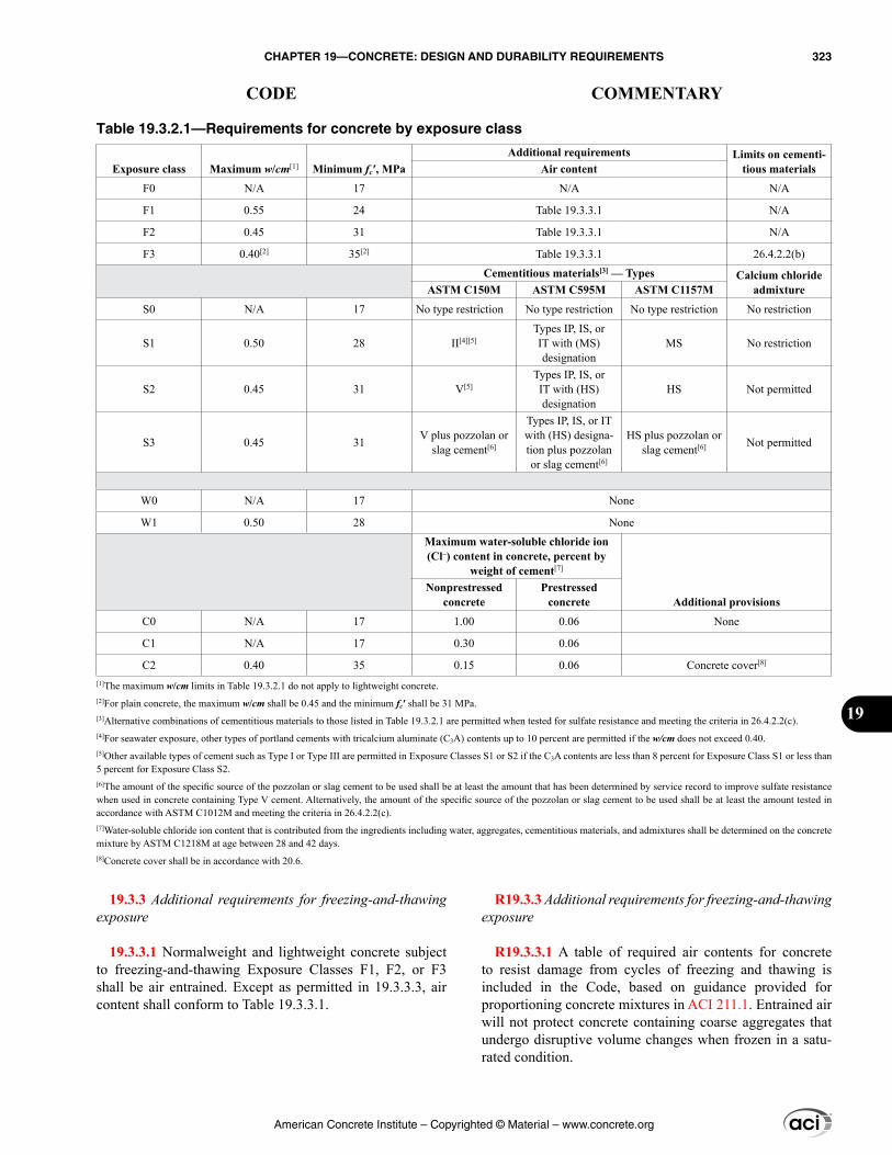
19.3.3 Additional requirements for freezing-and-thawing exposure
19.3.3.1 Normalweight and lightweight concrete subject to freezing-and-thawing Exposure Classes F1, F2, or F3 shall be air entrained. Except as permitted in 19.3.3.3, air content shall conform to Table 19.3.3.1.
R19.3.3 Additional requirements for freezing-and-thawing exposure
R19.3.3.1 A table of required air contents for concrete to resist damage from cycles of freezing and thawing is included in the Code, based on guidance provided for proportioning concrete mixtures in ACI 211.1. Entrained air will not protect concrete containing coarse aggregates that undergo disruptive volume changes when frozen in a satu-rated condition.
Table 19.3.2.1—Requirements for concrete by exposure class
Exposure class Maximum w/cm[1] Minimum fc′, MPaAdditional requirements Limits on cementi-
tious materialsAir content
F0 N/A 17 N/A N/A
F1 0.55 24 Table 19.3.3.1 N/A
F2 0.45 31 Table 19.3.3.1 N/A
F3 0.40[2] 35[2] Table 19.3.3.1 26.4.2.2(b)
Cementitious materials[3] — Types Calcium chloride admixtureASTM C150M ASTM C595M ASTM C1157M
S0 N/A 17 No type restriction No type restriction No type restriction No restriction
S1 0.50 28 II[4][5]Types IP, IS, or IT with (MS) designation
MS No restriction
S2 0.45 31 V[5]Types IP, IS, or IT with (HS) designation
HS Not permitted
S3 0.45 31 V plus pozzolan or slag cement[6]
Types IP, IS, or IT with (HS) designa-tion plus pozzolan or slag cement[6]
HS plus pozzolan or slag cement[6] Not permitted
W0 N/A 17 None
W1 0.50 28 None
Maximum water-soluble chloride ion (Cl–) content in concrete, percent by
weight of cement[7]
Additional provisionsNonprestressed
concretePrestressed
concrete
C0 N/A 17 1.00 0.06 None
C1 N/A 17 0.30 0.06
C2 0.40 35 0.15 0.06 Concrete cover[8]
[1]The maximum w/cm limits in Table 19.3.2.1 do not apply to lightweight concrete.[2]For plain concrete, the maximum w/cm shall be 0.45 and the minimum fc′ shall be 31 MPa.[3]Alternative combinations of cementitious materials to those listed in Table 19.3.2.1 are permitted when tested for sulfate resistance and meeting the criteria in 26.4.2.2(c).[4]For seawater exposure, other types of portland cements with tricalcium aluminate (C3A) contents up to 10 percent are permitted if the w/cm does not exceed 0.40.[5]Other available types of cement such as Type I or Type III are permitted in Exposure Classes S1 or S2 if the C3A contents are less than 8 percent for Exposure Class S1 or less than 5 percent for Exposure Class S2.[6]The amount of the specific source of the pozzolan or slag cement to be used shall be at least the amount that has been determined by service record to improve sulfate resistance when used in concrete containing Type V cement. Alternatively, the amount of the specific source of the pozzolan or slag cement to be used shall be at least the amount tested in accordance with ASTM C1012M and meeting the criteria in 26.4.2.2(c).[7]Water-soluble chloride ion content that is contributed from the ingredients including water, aggregates, cementitious materials, and admixtures shall be determined on the concrete mixture by ASTM C1218M at age between 28 and 42 days.[8]Concrete cover shall be in accordance with 20.6.
American Concrete Institute – Copyrighted © Material – www.concrete.org
CHAPTER 19—CONCRETE: DESIGN AND DURABILITY REQUIREMENTS 323
CODE COMMENTARY
19
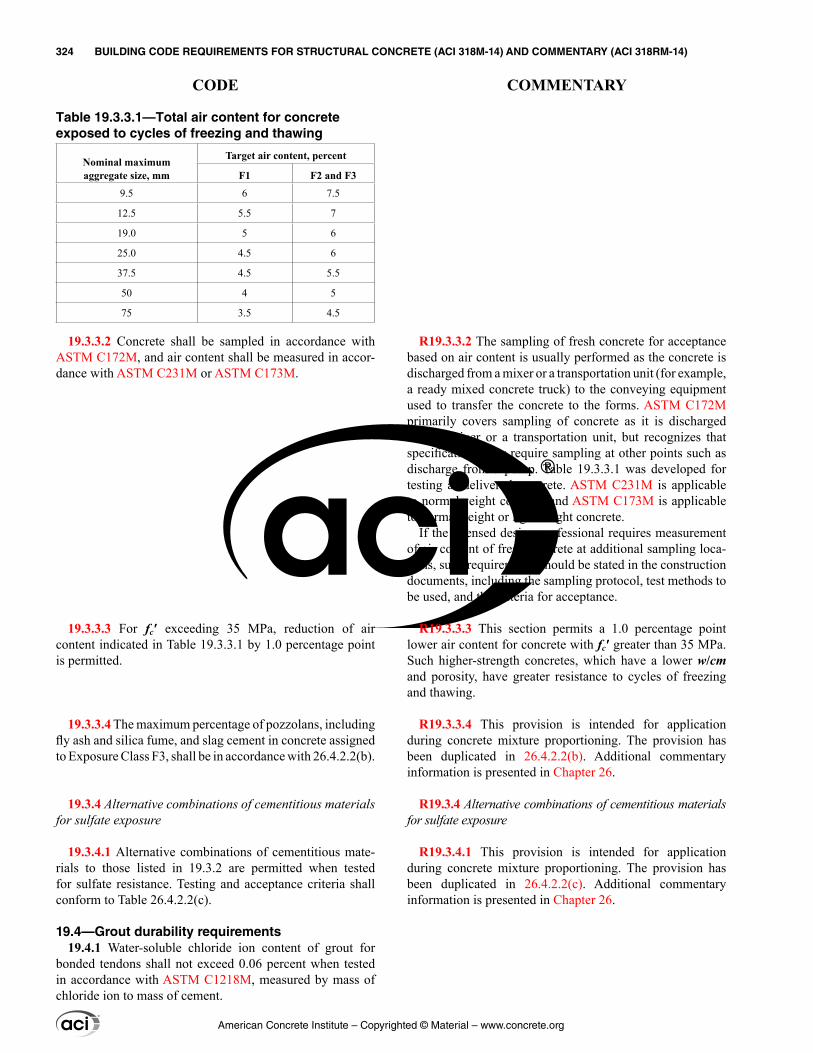
Table 19.3.3.1—Total air content for concrete exposed to cycles of freezing and thawing
Nominal maximum aggregate size, mm
Target air content, percent
F1 F2 and F3
9.5 6 7.5
12.5 5.5 7
19.0 5 6
25.0 4.5 6
37.5 4.5 5.5
50 4 5
75 3.5 4.5
19.3.3.2 Concrete shall be sampled in accordance with ASTM C172M, and air content shall be measured in accor-dance with ASTM C231M or ASTM C173M.
19.3.3.3 For fc′ exceeding 35 MPa, reduction of air content indicated in Table 19.3.3.1 by 1.0 percentage point is permitted.
19.3.3.4 The maximum percentage of pozzolans, including fly ash and silica fume, and slag cement in concrete assigned to Exposure Class F3, shall be in accordance with 26.4.2.2(b).
19.3.4 Alternative combinations of cementitious materials for sulfate exposure
19.3.4.1 Alternative combinations of cementitious mate-rials to those listed in 19.3.2 are permitted when tested for sulfate resistance. Testing and acceptance criteria shall conform to Table 26.4.2.2(c).
19.4—Grout durability requirements19.4.1 Water-soluble chloride ion content of grout for
bonded tendons shall not exceed 0.06 percent when tested in accordance with ASTM C1218M, measured by mass of chloride ion to mass of cement.
R19.3.3.2 The sampling of fresh concrete for acceptance based on air content is usually performed as the concrete is discharged from a mixer or a transportation unit (for example, a ready mixed concrete truck) to the conveying equipment used to transfer the concrete to the forms. ASTM C172M primarily covers sampling of concrete as it is discharged from a mixer or a transportation unit, but recognizes that specifications may require sampling at other points such as discharge from a pump. Table 19.3.3.1 was developed for testing as-delivered concrete. ASTM C231M is applicable to normalweight concrete and ASTM C173M is applicable to normalweight or lightweight concrete.
If the licensed design professional requires measurement of air content of fresh concrete at additional sampling loca-tions, such requirements should be stated in the construction documents, including the sampling protocol, test methods to be used, and the criteria for acceptance.
R19.3.3.3 This section permits a 1.0 percentage point lower air content for concrete with fc′ greater than 35 MPa. Such higher-strength concretes, which have a lower w/cm and porosity, have greater resistance to cycles of freezing and thawing.
R19.3.3.4 This provision is intended for application during concrete mixture proportioning. The provision has been duplicated in 26.4.2.2(b). Additional commentary information is presented in Chapter 26.
R19.3.4 Alternative combinations of cementitious materials for sulfate exposure
R19.3.4.1 This provision is intended for application during concrete mixture proportioning. The provision has been duplicated in 26.4.2.2(c). Additional commentary information is presented in Chapter 26.
American Concrete Institute – Copyrighted © Material – www.concrete.org
324 BUILDING CODE REQUIREMENTS FOR STRUCTURAL CONCRETE (ACI 318M-14) AND COMMENTARY (ACI 318RM-14)
CODE COMMENTARY
CHAPTER 20—STEEL REINFORCEMENT PROPERTIES, DURABILITY, AND EMBEDMENTS
20.1—Scope 20.1.1 This chapter shall apply to steel reinforcement, and
shall govern (a) through (c):
(a) Material properties(b) Properties to be used for design(c) Durability requirements, including minimum specified cover requirements
20.1.2 Provisions of 20.7 shall apply to embedments.
20.2—Nonprestressed bars and wires 20.2.1 Material properties
20.2.1.1 Nonprestressed bars and wires shall be deformed, except plain bars or wires are permitted for use in spirals.
20.2.1.2 Yield strength of nonprestressed bars and wires shall be determined by either (a) or (b):
(a) The offset method, using an offset of 0.2 percent in accordance with ASTM A370(b) The yield point by the halt-of-force method, provided the nonprestressed bar or wire has a sharp-kneed or well-defined yield point
20.2.1.3 Deformed bars shall conform to (a), (b), (c), (d), or (e):
(a) ASTM A615M – carbon steel(b) ASTM A706M – low-alloy steel(c) ASTM A996M – axle steel and rail steel; bars from rail steel shall be Type R(d) ASTM A955M – stainless steel(e) ASTM A1035M – low-carbon chromium steel
R20—STEEL REINFORCEMENT PROPERTIES, DURABILITY, AND EMBEDMENTS
R20.1—Scope R20.1.1 Materials permitted for use as reinforcement
are specified. Other metal elements, such as inserts, anchor bolts, or plain bars for dowels at isolation or contraction joints, are not normally considered reinforcement under the provisions of this Code. Fiber-reinforced polymer (FRP) reinforcement is not addressed in this Code. ACI Committee 440 has developed guidelines for the use of FRP reinforce-ment (ACI 440.1R and 440.2R).
R20.2—Nonprestressed bars and wires R20.2.1 Material properties
R20.2.1.2 The majority of nonprestressed steel bar rein-forcement exhibits actual stress-strain behavior that is sharply yielding or sharp-kneed (elasto-plastic stress-strain behavior). However, reinforcement products such as bars of higher strength grade, steel wire, coiled steel bar, and stain-less steel bars and wire generally do not exhibit sharply-yielding stress-strain behavior, but instead are gradually-yielding. The method used to measure yield strength of reinforcement needs to provide for both types of reinforce-ment stress-strain relationships.
A study (Paulson et al. 2013) considering reinforcement manufactured during 2008 through 2012 found that the offset method, using an offset of 0.2 percent, provides for a reasonable estimate of the strength of reinforced concrete structures.
The yield strength is determined by the manufacturer during tensile tests performed at the mill on samples of rein-forcement. Test methods for determining yield strength of steel, including the offset method and yield point by halt-of-force method, are referenced either in the ASTM standards for nonprestressed bars and wire or in ASTM A370 Test Methods and Definitions.
R20.2.1.3 Low-alloy steel deformed bars conforming to ASTM A706M are intended for applications where controlled tensile properties, restrictions on chemical composition to enhance weldability, or both, are required.
Rail-steel deformed bars used with this Code are required to conform to ASTM A996M, including the provisions for Type R bars. Type R bars are required to meet more restric-tive provisions for bend tests than other types of rail steel.
Stainless steel deformed bars are used in applications where high corrosion resistance or controlled magnetic permeability are required.
American Concrete Institute – Copyrighted © Material – www.concrete.org
CHAPTER 20—STEEL REINFORCEMENT PROPERTIES, DURABILITY, AND EMBEDMENTS 325
CODE COMMENTARY
20
Low-carbon chromium steel is a high-strength material that is permitted for use as transverse reinforcement for confine-ment in special earthquake-resistant structural systems and spirals in columns. Refer to Tables 20.2.2.4a and b. ASTM A1035M provides requirements for bars of two minimum yield strength levels—700 MPa and 830 MPa—designated as Grade 690 and Grade 830, respectively, but the maximum fyt permitted for design calculations in this Code is limited in accordance with 20.2.2.3.
R20.2.1.4 Plain bars are permitted only for spiral rein-forcement used as transverse reinforcement for columns, transverse reinforcement for shear and torsion, or confining reinforcement for splices.
R20.2.1.6 The limitation to Class HA head dimensions from Annex A1 of ASTM A970M is due to a lack of test data for headed deformed bars that do not meet Class HA dimensional requirements. Heads not conforming to Class HA limits on bar deformation obstructions and bearing face features could cause unintended splitting forces in the concrete that may not be characteristic of the heads used in the tests that were the basis for 25.4.4. For heads conforming to Class HA dimensional requirements, the net bearing area of the head can be assumed to be equal to the gross area of the head minus the area of the bar. This assumption may not be valid for heads not conforming to Class HA dimensional requirements.
R20.2.1.7 Plain wire is permitted only for spiral reinforce-ment and in welded plain wire reinforcement, the latter of which is considered deformed. Stainless steel wire and stain-less steel welded wire reinforcement are used in applications where high corrosion resistance or controlled magnetic permeability is required. The physical and mechanical property requirements for deformed stainless steel wire and deformed and plain welded wire reinforcement under ASTM A1022M are the same as those for deformed wire, deformed welded wire reinforcement, and plain welded wire reinforce-ment under ASTM A1064M.
R20.2.1.7.1 An upper limit is placed on the size of deformed wire because tests (Rutledge and Devries 2002) have shown that MD290 wire will achieve only approxi-mately 60 percent of the bond strength in tension given by Eq. (25.4.2.3a).
20.2.1.4 Plain bars for spiral reinforcement shall conform to ASTM A615M, A706M, A955M, or A1035M.
20.2.1.5 Welded deformed bar mats shall conform to ASTM A184M. Deformed bars used in welded deformed bar mats shall conform to ASTM A615M or A706M.
20.2.1.6 Headed deformed bars shall conform to ASTM A970M, including Annex A1 requirements for Class HA head dimensions.
20.2.1.7 Deformed wire, plain wire, welded deformed wire reinforcement, and welded plain wire reinforcement shall conform to (a) or (b), except that yield strength shall be determined in accordance with 20.2.1.2:
(a) A1064M – carbon steel (b) A1022M – stainless steel
20.2.1.7.1 Deformed wire sizes MD25 through MD200 shall be permitted.
20.2.1.7.2 Deformed wire sizes larger than MD200 shall be permitted in welded wire reinforcement if treated as plain wire for calculation of development and splice lengths in accordance with 25.4.7 and 25.5.4, respectively.
American Concrete Institute – Copyrighted © Material – www.concrete.org
326 BUILDING CODE REQUIREMENTS FOR STRUCTURAL CONCRETE (ACI 318M-14) AND COMMENTARY (ACI 318RM-14)
CODE COMMENTARY
R20.2.2 Design properties
R20.2.2.1 For deformed reinforcement, it is reasonably accurate to assume that the stress in reinforcement is propor-tional to strain below the specified yield strength fy. The increase in strength due to the effect of strain hardening of the reinforcement is neglected for nominal strength calcula-tions. In nominal strength calculations, the force developed in tension or compression reinforcement is calculated as:
if εs < εy (yield strain)
Asfs = AsEsεs
if εs ≥ εy
Asfs = Asfy
where εs is the value from the strain diagram at the location of the reinforcement.
R20.2.2.4 Tables 20.2.2.4a and b limit the maximum values of yield strength to be used in design calculations for nonprestressed deformed reinforcement and nonprestressed plain spiral reinforcement, respectively.
In Table 20.2.2.4a, for deformed reinforcement in special moment frames and special structural walls, the use of longi-tudinal reinforcement with strength substantially higher than that assumed in design will lead to higher shear and bond stresses at the time of development of yield moments. These conditions may lead to brittle failures in shear or bond and should be avoided even if such failures may occur at higher loads than those anticipated in design. Therefore, a limit is placed on the actual yield strength of the steel (refer to 20.2.2.5). ASTM A706M for low-alloy steel reinforcing bars now includes both Grade 420 and Grade 550; however, only Grade 420 is permitted for special seismic systems because of insufficient data to confirm applicability of existing code provisions for structures using the higher grade. For beams, the deflection provisions of 24.2 and the limitations
20.2.1.7.3 Except as permitted for welded wire reinforce-ment used as stirrups in accordance with 25.7.1, spacing of welded intersections in welded wire reinforcement in the direction of calculated stress shall not exceed (a) or (b):
(a) 400 mm for welded deformed wire reinforcement (b) 300 mm for welded plain wire reinforcement
20.2.2 Design properties
20.2.2.1 For nonprestressed bars and wires, the stress below fy shall be Es times steel strain. For strains greater than that corresponding to fy, stress shall be considered inde-pendent of strain and equal to fy.
20.2.2.2 Modulus of elasticity, Es, for nonprestressed bars and wires shall be permitted to be taken as 200,000 MPa.
20.2.2.3 Yield strength for nonprestressed bars and wires shall be based on the specified grade of reinforcement and shall not exceed the values given in 20.2.2.4 for the associ-ated applications.
20.2.2.4 Types of nonprestressed bars and wires to be specified for particular structural applications shall be in accordance with Table 20.2.2.4a for deformed reinforcement and Table 20.2.2.4b for plain reinforcement.
American Concrete Institute – Copyrighted © Material – www.concrete.org
CHAPTER 20—STEEL REINFORCEMENT PROPERTIES, DURABILITY, AND EMBEDMENTS 327
CODE COMMENTARY
20
on distribution of flexural reinforcement of 24.3 become increasingly critical as fy increases.
The maximum value of yield strength for calculation purposes is limited to 700 MPa for both nonprestressed deformed reinforcement and plain spiral reinforcement in Tables 20.2.2.4a and b, respectively, when used for lateral support of longitudinal bars or for concrete confinement. The research that supports this limit for confinement is given in Saatcioglu and Razvi (2002), Pessiki et al. (2001), and Richart et al. (1929). For reinforcement in special moment frames and special structural walls, the research that indi-cated that higher yield strengths can be used effectively for confinement reinforcement is given in Budek et al. (2002), Muguruma and Watanabe (1990), and Sugano et al. (1990).
The limit of 420 MPa on the values of fy and fyt used in design for most shear and torsional reinforcement is intended to control width of inclined cracks. The higher yield strength of 550 MPa permitted in shear design for welded deformed wire reinforcement is also intended to control width of inclined cracks and is based on Guimares et al. (1992), Griezic et al. (1994), and Furlong et al. (1991). In particular, full-scale beam tests described in Griezic et al. (1994) indi-cated that the widths of inclined shear cracks at service load levels were less for beams reinforced with smaller diameter welded deformed wire reinforcement cages designed on the basis of a yield strength of 520 MPa than beams reinforced with deformed Grade 420 stirrups.
Footnote 2 of Table 20.2.2.4a is provided because ASTM A1064M and A1022M only require the welds to develop 240 MPa in the interconnected wires. Hoops, stirrups, and other elements used in special seismic systems should have anchorages that are capable of developing 1.25fy or 1.25fyt, as applicable, or tensile strength of the bar or wire, whichever is less, so that moderate ductility capacity can be achieved. A welded product that is capable of developing these stress limits could be approved for use through Code Section 1.10.
American Concrete Institute – Copyrighted © Material – www.concrete.org
328 BUILDING CODE REQUIREMENTS FOR STRUCTURAL CONCRETE (ACI 318M-14) AND COMMENTARY (ACI 318RM-14)
CODE COMMENTARY
R20.2.2.5 The requirement for the tensile strength to be greater than the yield strength of the reinforcement by a factor of 1.25 is based on the assumption that the capa-bility of a structural member to develop inelastic rotation capacity is a function of the length of the yield region along the axis of the member. In interpreting experimental results, the length of the yield region has been related to the rela-tive magnitudes of probable and yield moments (ACI 352R). According to this interpretation, the greater the ratio of prob-able-to-yield moment, the longer the yield region. Members with reinforcement not satisfying this condition can also develop inelastic rotation, but their behavior is sufficiently different to exclude them from direct consideration on the basis of rules derived from experience with members rein-forced with strain-hardening steel.
For ASTM A615M Grade 420 deformed reinforcement, the requirements for minimum elongation were added to the 2014 Code. The required minimum elongations in 20.2.2.5 are the same as the values in ASTM A706M for Grade 420 deformed reinforcement.
20.2.2.5 Deformed nonprestressed longitudinal reinforce-ment resisting earthquake-induced moment, axial force, or both, in special moment frames, special structural walls, and all components of special structural walls including coupling beams and wall piers shall be in accordance with (a) or (b):
(a) ASTM A706M, Grade 420(b) ASTM A615M Grade 280 reinforcement if (i) and (ii) are satisfied and ASTM A615M Grade 420 reinforcement if (i) through (iii) are satisfied.
(i) Actual yield strength based on mill tests does not exceed fy by more than 125 MPa (ii) Ratio of the actual tensile strength to the actual yield strength is at least 1.25(iii) Minimum elongation in 200 mm shall be at least 14 percent for bar sizes No. 10 through No. 19, at least 12 percent for bar sizes No. 22 through No. 36, and at least 10 percent for bar sizes No. 43 and No. 57.
Table 20.2.2.4a—Nonprestressed deformed reinforcement
Usage Application
Maximum value of fy or fyt permitted
for designcalculations, MPa
Applicable ASTM specification
Deformedbars
Deformedwires
Welded wire reinforcement
Welded deformed bar
matsFlexure; axial
force; and shrinkage and temperature
Special seismic systems 420 Refer to 20.2.2.5 Not permitted Not permitted Not permitted
Other 550 A615M, A706M, A955M, A996M A1064M, A1022M A1064M, A1022M A184M[1]
Lateral support of longitudinal
bars; or concrete confinement
Special seismic systems 700 A615M, A706M, A955M,
A996M, A1035M A1064M, A1022M A1064M[2], A1022M[2] Not permitted
Spirals 700 A615M, A706M, A955M, A996M, A1035M A1064M, A1022M Not permitted Not permitted
Other 550 A615M, A706M, A955M, A996M A1064M, A1022M A1064M, A1022M Not permitted
Shear
Special seismic systems 420 A615M, A706M, A955M,
A996M A1064M, A1022M A1064M[2], A1022M[2] Not permitted
Spirals 420 A615M, A706M, A955M, A996M A1064M, A1022M Not permitted Not permittedShear friction 420 A615M, A706M, A955M, A996M A1064M, A1022M A1064M, A1022M Not permitted
Stirrups, ties, hoops
420 A615M, A706M, A955M, A996M A1064M, A1022M A1064M and A1022M
welded plain wire Not permitted
550 Not permitted Not permitted A1064M and A1022Mwelded deformed wire Not permitted
Torsion Longitudinal and transverse 420 A615M, A706M, A955M,
A996M A1064M, A1022M A1064M, A1022M Not permitted
[1]Welded deformed bar mats shall be permitted to be assembled using A615M or A706M deformed bars.
[2] ASTM A1064M and A1022M are not permitted in special seismic systems where the weld is required to resist stresses in response to confinement, lateral support of longitudinal bars, shear, or other actions.
Table 20.2.2.4b—Nonprestressed plain spiral reinforcement
Usage Application
Maximum value of fy or fyt permitted for design
calculations, MPa
Applicable ASTM specification
Plain bars Plain wiresLateral support of longi-tudinal bars; or concrete
confinement
Spirals in special seismic systems 700 A615M, A706M, A955M, A1035M A1064M, A1022M
Spirals 700 A615M, A706M, A955M, A1035M A1064M, A1022M
Shear Spirals 420 A615M, A706M, A955M, A1035M A1064M, A1022M
Torsion in nonprestressed beams Spirals 420 A615M, A706M, A955M, A1035M A1064M, A1022M
American Concrete Institute – Copyrighted © Material – www.concrete.org
CHAPTER 20—STEEL REINFORCEMENT PROPERTIES, DURABILITY, AND EMBEDMENTS 329
CODE COMMENTARY
20
20.3—Prestressing strands, wires, and bars 20.3.1 Material properties
20.3.1.1 Except as required in 20.3.1.3 for special moment frames and special structural walls, prestressing reinforce-ment shall conform to (a), (b), (c), or (d):
(a) ASTM A416M – strand(b) ASTM A421M – wire(c) ASTM A421M – low-relaxation wire including Supple-mentary Requirement S1, “Low-Relaxation Wire and Relaxation Testing”(d) ASTM A722M – high-strength bar
20.3.1.2 Prestressing strands, wires, and bars not listed in ASTM A416M, A421M, or A722M are permitted provided they conform to minimum requirements of these specifica-tions and are shown by test or analysis not to impair the performance of the member.
20.3.1.3 Prestressing reinforcement resisting earthquake-induced moment, axial force, or both, in special moment frames, special structural walls, and all components of special structural walls including coupling beams and wall piers, cast using precast concrete shall comply with ASTM A416M or A722M.
20.3.2 Design properties
20.3.2.1 Modulus of elasticity, Ep, for prestressing rein-forcement shall be determined from tests or as reported by the manufacturer.
20.3.2.2 Tensile strength, fpu, shall be based on the speci-fied grade or type of prestressing reinforcement and shall not exceed the values given in Table 20.3.2.2.
Table 20.3.2.2—Prestressing strands, wires, and bars
Type
Maximum value of fpu permitted for design calcu-
lations, MPa Applicable ASTM SpecificationStrand (stress-relieved and
low-relaxation)1860 A416M
Wire (stress-relieved and
low-relaxation)1725
A421M
A421M, including Supplementary Requirement S1 “Low-Relaxation
Wire and Relaxation Testing”High-strength
bar 1035 A722M
20.3.2.3 Stress in bonded prestressed reinforcement at nominal flexural strength, fps
R20.3—Prestressing strands, wires, and bars R20.3.1 Material properties
R20.3.1.1 Because low-relaxation prestressing reinforce-ment is addressed in a supplementary requirement to ASTM A421M, which applies only if low-relaxation material is specified, the appropriate ASTM reference is listed as a separate entity.
R20.3.2 Design properties
R20.3.2.1 Default values of Ep between 197,000 and 200,000 MPa are commonly used for design purposes. More accurate values based on tests or the manufactur-er’s reports may be needed for elongation checks during stressing.
R20.3.2.2 ASTM A416M specifies two grades of strand tensile strength: 1725 and 1860 MPa.
ASTM A421M specifies tensile strengths of 1620, 1655, and 1725 MPa, depending on the diameter and type of wire. For the most common diameter, 6 mm, ASTM A421M spec-ifies a tensile strength of 1655 MPa.
R20.3.2.3 Stress in bonded prestressed reinforcement at nominal flexural strength, fps
American Concrete Institute – Copyrighted © Material – www.concrete.org
330 BUILDING CODE REQUIREMENTS FOR STRUCTURAL CONCRETE (ACI 318M-14) AND COMMENTARY (ACI 318RM-14)
CODE COMMENTARY
20.3.2.3.1 As an alternative to a more accurate calcula-tion of fps based on strain compatibility, values of fps calcu-lated in accordance with Eq. (20.3.2.3.1) shall be permitted for members with bonded prestressed reinforcement if all prestressed reinforcement is in the tension zone and fse ≥ 0.5fpu.
( )1
1 p pu yps pu p
c p c
f fdf ff d f
γ = − ρ + ρ − ρ′ β ′ ′ (20.3.2.3.1)
where γp is in accordance with Table 20.3.2.3.1.If compression reinforcement is considered for the calcu-
lation of fps by Eq. (20.3.2.3.1), (a) and (b) shall be satisfied.
(a) If d′ exceeds 0.15dp, the compression reinforcement shall be neglected in Eq. (20.3.2.3.1).
(b) If compression reinforcement is included in Eq. (20.3.2.3.1), the term
( )pu y
pc p c
f fdf d f
ρ + ρ − ρ′
′ ′
shall not be taken less than 0.17.
Table 20.3.2.3.1—Values of γp for use in Eq. (20.3.2.3.1)
fpy/fpu γp
≥ 0.80 0.55
≥ 0.85 0.40
≥ 0.90 0.28
20.3.2.3.2 For pretensioned strands, the strand design stress at sections of members located within ℓd from the free end of strand shall not exceed that calculated in accordance with 25.4.8.3.
20.3.2.4 Stress in unbonded prestressed reinforcement at nominal flexural strength, fps
R20.3.2.3.1 Use of Eq. (20.3.2.3.1) may underestimate the strength of beams with high percentages of reinforce-ment and, for more accurate evaluations of their strength, the strain compatibility and equilibrium method should be used. If part of the prestressed reinforcement is in the compression zone, a strain compatibility and equilibrium method should be used.
The γp term in Eq. (20.3.2.3.1) and Table 20.3.2.3.1 reflects the influence of different types of prestressing reinforcement on the value of fps. Table R20.3.2.3.1 shows prestressed rein-forcement type and the associated ratio fpy/fpu.
R20.3.2.3.1(a) If d′ is large, the strain in compression reinforcement can be considerably less than its yield strain. In such a case, the compression reinforcement does not influ-ence fps as favorably as implied by Eq. (20.3.2.3.1). For this reason, if d′ exceeds 0.15dp, Eq. (20.3.2.3.1) is applicable only if the compression reinforcement is neglected.
R20.3.2.3.1(b) The ρ′ term in Eq. (20.3.2.3.1) reflects the increased value of fps obtained when compression rein-forcement is provided in a beam with a large reinforcement index. If the term [ρp(fpu/fc′) + (d/dp)(fy/fc′)(ρ – ρ′)] is small, the neutral axis depth is small, the compressive reinforce-ment does not develop its yield strength, and Eq. (20.3.2.3.1) becomes unconservative. For this reason, the term [ρp(fpu/fc′) + (d/dp)(fy/fc′)(ρ – ρ′)] may not be taken less than 0.17 if compression reinforcement is taken into account when calculating fps. The compression reinforcement may be conservatively neglected when using Eq. (20.3.2.3.1) by taking ρ′ as zero, in which case the term [ρp(fpu/fc′) + (d/dp)(fy/fc′)(ρ)] may be less than 0.17 and an acceptable value of fps is obtained.
Table R20.3.2.3.1—Ratio of fpy/fpu associated with reinforcement type
Prestressed reinforcement type fpy/fpu
High-strength pre-stressing bars
ASTM A722M Type I (Plain) ≥ 0.85
ASTM A722M Type II (Deformed) ≥ 0.80
Stress-relieved strand and wire
ASTM A416MASTM A421M ≥ 0.85
Low-relaxation strand and wire
ASTM A416MASTM A421M ≥ 0.90
R20.3.2.4 Stress in unbonded prestressed reinforcement at nominal flexural strength, fps
American Concrete Institute – Copyrighted © Material – www.concrete.org
CHAPTER 20—STEEL REINFORCEMENT PROPERTIES, DURABILITY, AND EMBEDMENTS 331
CODE COMMENTARY
20
20.3.2.4.1 As an alternative to a more accurate calcula-tion of fps, values of fps calculated in accordance with Table 20.3.2.4.1 shall be permitted for members prestressed with unbonded tendons if fse ≥ 0.5fpu.
Table 20.3.2.4.1—Approximate values of fps at nominal flexural strength for unbonded tendons
ℓn/h fps
≤ 35 The least of:fse + 70 + fc′/(100ρp)
fse + 420fpy
> 35 The least of:fse + 70 + fc′/(300ρp)
fse + 210fpy
20.3.2.5 Permissible tensile stresses in prestressed reinforcement
20.3.2.5.1 The tensile stress in prestressed reinforcement shall not exceed the limits in Table 20.3.2.5.1.
Table 20.3.2.5.1—Maximum permissible tensile stresses in prestressed reinforcement
Stage Location Maximum tensile stress
During stressing At jacking end Least
of:
0.94fpy
0.80fpu
Maximum jacking force rec-ommended by the supplier
of anchorage deviceImmediately after force
transfer
At post-tensioning anchorage devices
and couplers0.70fpu
20.3.2.6 Prestress losses
20.3.2.6.1 Prestress losses shall be considered in the calculation of the effective tensile stress in the prestressed reinforcement, fse, and shall include (a) through (f):
(a) Prestressed reinforcement seating at transfer(b) Elastic shortening of concrete(c) Creep of concrete(d) Shrinkage of concrete(e) Relaxation of prestressed reinforcement(f) Friction loss due to intended or unintended curvature in post-tensioning tendons
20.3.2.6.2 Calculated friction loss in post-tensioning tendons shall be based on experimentally determined wobble and curvature friction coefficients.
R20.3.2.4.1 The term [fse + 70 + fc′/(300ρp)] reflects results of tests on members with unbonded tendons and span-to-depth ratios greater than 35 (one-way slabs, flat plates, and flat slabs) (Mojtahedi and Gamble 1978). These tests also indicate that the term [fse + 70 + fc′/(100ρp)], formerly used for all span-depth ratios, overestimates the amount of stress increase in such members. Although these same tests indi-cate that the moment strength of those shallow members designed using [fse + 70 + fc′/(100ρp)] meets the factored load strength requirements, this reflects the effect of the Code requirements for minimum bonded reinforcement as well as the limitation on concrete tensile stress that often control the amount of prestressing force provided.
R20.3.2.5 Permissible tensile stresses in prestressed reinforcement
R20.3.2.5.1 Because of the high yield strength of low-relaxation strand and wire meeting the requirements of ASTM A416M and A421M including Supplementary Requirement S1 “Low-Relaxation Wire and Relaxation Testing,” it is appropriate to specify permissible stresses in terms of speci-fied minimum ASTM yield strength along with the speci-fied minimum ASTM tensile strength. Because of the higher allowable initial prestressing steel stresses permitted since the 1983 Code, final stresses can be greater. For structures subject to corrosive conditions or repeated loadings, consid-eration should be given to limiting the final stress.
R20.3.2.6 Prestress losses
R20.3.2.6.1 For an explanation of how to calculate prestress losses, see Joint ACI-ASCE Committee 423 (1958), ACI 435R, PCI Committee on Prestress Losses (1975), and Zia et al. (1979). Reasonably accurate estimates of prestress losses can be calculated in accordance with the recommen-dations in Zia et al. (1979), which include consideration of initial stress level (0.7fpu or higher), type of steel (stress-relieved or low-relaxation wire, strand, or bar), exposure conditions, and type of construction (pretensioned, bonded post-tensioned, or unbonded post-tensioned).
Actual losses, greater or smaller than the calculated values, have little effect on the design strength of the member, but affect service load behavior (deflections, camber, cracking load) and connections. At service loads, overestimation of prestress losses can be almost as detrimental as underestima-tion because the former can result in excessive camber and horizontal movement.
R20.3.2.6.2 Estimation of friction losses in post-tensioned tendons is addressed in PTI TAB.1. Values of the wobble and curvature friction coefficients to be used for the partic-
American Concrete Institute – Copyrighted © Material – www.concrete.org
332 BUILDING CODE REQUIREMENTS FOR STRUCTURAL CONCRETE (ACI 318M-14) AND COMMENTARY (ACI 318RM-14)
CODE COMMENTARY
20.3.2.6.3 Where loss of prestress in a member is anticipated due to connection of the member to adjoining construction, such loss of prestress shall be included in design calculations.
20.4—Structural steel, pipe, and tubing for composite columns
20.4.1 Material properties
20.4.1.1 Structural steel other than steel pipe or tubing used in composite columns shall conform to (a), (b), (c), (d), or (e):
(a) ASTM A36M – carbon steel(b) ASTM A242M – high-strength low-alloy steel(c) ASTM A572M – high-strength, low-alloy, columbium-vanadium steel(d) ASTM A588M – high-strength, low-alloy, 345 MPa steel(e) ASTM A992M – structural shapes
20.4.1.2 Steel pipe or tubing used in composite columns to encase a concrete core shall conform to (a), (b), (c), or (d):
(a) ASTM A53M Grade B – black steel, hot-dipped, zinc-coated(b) ASTM A500M – cold-formed, welded, seamless(c) ASTM A501 – hot-formed, welded, seamless(d) ASTM A1085 – cold-formed, welded
20.4.2 Design properties
20.4.2.1 For structural steel in composite columns, maximum value of fy shall be in accordance with the appro-priate ASTM standards in 20.4.1.
20.4.2.2 For structural steel used in composite columns with a structural steel core, value of fy shall not exceed 350 MPa.
ular types of prestressing reinforcement and particular types of ducts should be obtained from the manufacturers of the tendons. An unrealistically low estimate of the friction loss can lead to improper camber, or potential deflection, of the member and inadequate prestress. Overestimation of the friction may result in extra prestressing force. This could lead to excessive camber and excessive shortening of a member. If the friction factors are determined to be less than those assumed in the design, the tendon stressing should be adjusted to provide only that prestressing force in the critical portions of the structure required by the design.
When safety or serviceability of the structure may be involved, the acceptable range of prestressing reinforcement jacking forces or other limiting requirements should either be given or approved by the licensed design professional in conformance with the permissible stresses of 20.3.2.5 and 24.5.
R20.4—Structural steel, pipe, and tubing for composite columns
R20.4.2 Design properties
R20.4.2.2 The design yield strength of the steel core should be limited to that which would not generate spalling of the concrete. It has been assumed that axially compressed concrete will not spall at strains less than 0.0018. The yield
American Concrete Institute – Copyrighted © Material – www.concrete.org
CHAPTER 20—STEEL REINFORCEMENT PROPERTIES, DURABILITY, AND EMBEDMENTS 333
CODE COMMENTARY
20
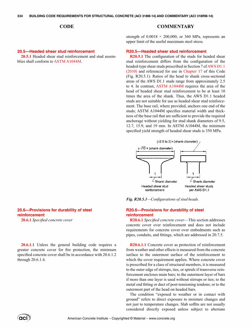
20.5—Headed shear stud reinforcement 20.5.1 Headed shear stud reinforcement and stud assem-
blies shall conform to ASTM A1044M.
20.6—Provisions for durability of steel reinforcement
20.6.1 Specified concrete cover
20.6.1.1 Unless the general building code requires a greater concrete cover for fire protection, the minimum specified concrete cover shall be in accordance with 20.6.1.2 through 20.6.1.4.
strength of 0.0018 × 200,000, or 360 MPa, represents an upper limit of the useful maximum steel stress.
R20.5—Headed shear stud reinforcement R20.5.1 The configuration of the studs for headed shear
stud reinforcement differs from the configuration of the headed-type shear studs prescribed in Section 7 of AWS D1.1 (2010) and referenced for use in Chapter 17 of this Code (Fig. R20.5.1). Ratios of the head to shank cross-sectional areas of the AWS D1.1 studs range from approximately 2.5 to 4. In contrast, ASTM A1044M requires the area of the head of headed shear stud reinforcement to be at least 10 times the area of the shank. Thus, the AWS D1.1 headed studs are not suitable for use as headed shear stud reinforce-ment. The base rail, where provided, anchors one end of the studs; ASTM A1044M specifies material width and thick-ness of the base rail that are sufficient to provide the required anchorage without yielding for stud shank diameters of 9.5, 12.7, 15.9, and 19 mm. In ASTM A1044M, the minimum specified yield strength of headed shear studs is 350 MPa.
R20.6—Provisions for durability of steel reinforcement
R20.6.1 Specified concrete cover—This section addresses concrete cover over reinforcement and does not include requirements for concrete cover over embedments such as pipes, conduits, and fittings, which are addressed in 20.7.5.
R20.6.1.1 Concrete cover as protection of reinforcement from weather and other effects is measured from the concrete surface to the outermost surface of the reinforcement to which the cover requirement applies. Where concrete cover is prescribed for a class of structural members, it is measured to the outer edge of stirrups, ties, or spirals if transverse rein-forcement encloses main bars; to the outermost layer of bars if more than one layer is used without stirrups or ties; to the metal end fitting or duct of post-tensioning tendons; or to the outermost part of the head on headed bars.
The condition “exposed to weather or in contact with ground” refers to direct exposure to moisture changes and not just to temperature changes. Slab soffits are not usually considered directly exposed unless subject to alternate
Fig. R20.5.1—Configurations of stud heads.
American Concrete Institute – Copyrighted © Material – www.concrete.org
334 BUILDING CODE REQUIREMENTS FOR STRUCTURAL CONCRETE (ACI 318M-14) AND COMMENTARY (ACI 318RM-14)
CODE COMMENTARY
wetting and drying, including that due to condensation conditions or direct leakage from exposed top surface, run off, or similar effects.
Alternative methods of protecting the reinforcement from weather may be provided if they are equivalent to the addi-tional concrete cover required by the Code. When approved by the building official under the provisions of 1.10, rein-forcement with alternative protection from weather may not have concrete cover less than the cover required for rein-forcement not exposed to weather.
Development length provisions given in Chapter 25 are a function of cover over the reinforcement. To meet require-ments for development length, it may be necessary to use cover greater than the minimums specified in 20.6.1.
R20.6.1.2 Concrete floor finishes may be considered for nonstructural purposes such as cover for reinforcement and fire protection. Provisions should be made, however, to ensure that the concrete finish will not spall off, thus resulting in decreased cover. Furthermore, considerations for development of reinforcement require minimum mono-lithic concrete cover in accordance with 20.6.1.3.
R20.6.1.3 Specified concrete cover requirements
20.6.1.2 It shall be permitted to consider concrete floor finishes as part of required cover for nonstructural purposes.
20.6.1.3 Specified concrete cover requirements
20.6.1.3.1 Nonprestressed cast-in-place concrete members shall have specified concrete cover for reinforcement at least that given in Table 20.6.1.3.1.
Table 20.6.1.3.1—Specified concrete cover for cast-in-place nonprestressed concrete members
Concrete exposure Member ReinforcementSpecified
cover, mmCast against and permanently in
contact with groundAll All 75
Exposed to weather or in contact with
groundAll
No. 19 through No. 57 bars 50
No. 16 bar, MW200 or MD200 wire, and
smaller40
Not exposed to weather or in
contact with ground
Slabs, joists, and walls
No. 43 and No. 57 bars 40
No. 36 bar and smaller 20
Beams, columns,
pedestals, and tension ties
Primary reinforce-ment, stirrups, ties, spirals, and hoops
40
20.6.1.3.2 Cast-in-place prestressed concrete members shall have specified concrete cover for reinforcement, ducts, and end fittings at least that given in Table 20.6.1.3.2.
American Concrete Institute – Copyrighted © Material – www.concrete.org
CHAPTER 20—STEEL REINFORCEMENT PROPERTIES, DURABILITY, AND EMBEDMENTS 335
CODE COMMENTARY
20
R20.6.1.3.3 The lesser cover thicknesses for precast construction reflect the greater control for proportioning, placing, and curing inherent in precasting. Manufactured under plant conditions does not imply that precast members should be manufactured in a plant. Structural elements precast at the job site will also qualify under this section if the control of form dimensions, placing of reinforcement, quality control of concrete, and curing procedures are equal to that normally expected in a plant.
Concrete cover to pretensioned strand as described in this section is intended to provide minimum protection from weather and other effects. Such cover may not be sufficient to transfer or develop the stress in the strand, and it may be necessary to increase the cover accordingly.
Table 20.6.1.3.2—Specified concrete cover for cast-in-place prestressed concrete members
Concrete exposure Member Reinforcement
Specified cover,mm
Cast against and permanently
in contact with ground
All All 75
Exposed to weather or in contact with
ground
Slabs, joists, and walls All 25
All other All 40
Not exposed to weather or
in contact with ground
Slabs, joists, and walls All 20
Beams, columns, and tension ties
Primary reinforcement 40
Stirrups, ties, spirals, and
hoops25
20.6.1.3.3 Precast nonprestressed or prestressed concrete members manufactured under plant conditions shall have specified concrete cover for reinforcement, ducts, and end fittings at least that given in Table 20.6.1.3.3.
Table 20.6.1.3.3—Specified concrete cover for precast nonprestressed or prestressed concrete members manufactured under plant conditions
Concrete exposure Member Reinforcement
Specified cover, mm
Exposed to weather
or in contact
with ground
Walls
No. 43 and No. 57 bars; tendons larger than 40 mm diameter 40
No. 36 bars and smaller; MW200 and MD200 wire and smaller; ten-dons and strands 40 mm diameter
and smaller
20
All other
No. 43 and No. 57 bars; tendons larger than 40 mm diameter 50
No. 19 through No. 36 bars; tendons and strands larger than 16 mm
diameter through 40 mm diameter40
No. 16 bar, MW200 or MD200 wire, and smaller; tendons and strands 16
mm diameter and smaller30
Not exposed
to weather or in
contact with
ground
Slabs, joists, and
walls
No. 43 and No. 57 bars;tendons larger than 40 mm
diameter30
Tendons and strands 40 mmdiameter and smaller 20
No. 36 bar, MW200 or MD200 wire, and smaller 16
Beams, columns, pedestals,
andtension
ties
Primary reinforcement
Greater of db and 16 and need
not exceed 40
Stirrups, ties, spirals, and hoops 10
20.6.1.3.4 For bundled bars, specified concrete cover shall be at least the smaller of (a) and (b):
American Concrete Institute – Copyrighted © Material – www.concrete.org
336 BUILDING CODE REQUIREMENTS FOR STRUCTURAL CONCRETE (ACI 318M-14) AND COMMENTARY (ACI 318RM-14)
CODE COMMENTARY
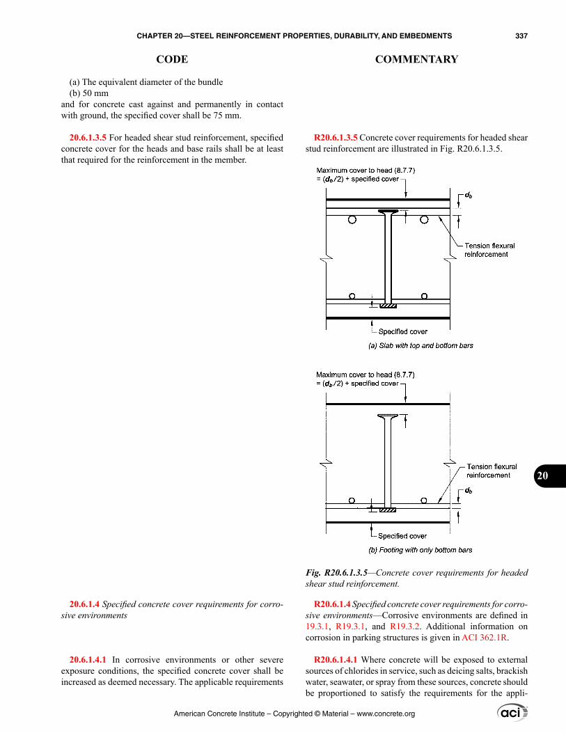
R20.6.1.3.5 Concrete cover requirements for headed shear stud reinforcement are illustrated in Fig. R20.6.1.3.5.
R20.6.1.4 Specified concrete cover requirements for corro-sive environments—Corrosive environments are defined in 19.3.1, R19.3.1, and R19.3.2. Additional information on corrosion in parking structures is given in ACI 362.1R.
R20.6.1.4.1 Where concrete will be exposed to external sources of chlorides in service, such as deicing salts, brackish water, seawater, or spray from these sources, concrete should be proportioned to satisfy the requirements for the appli-
(a) The equivalent diameter of the bundle(b) 50 mm
and for concrete cast against and permanently in contact with ground, the specified cover shall be 75 mm.
20.6.1.3.5 For headed shear stud reinforcement, specified concrete cover for the heads and base rails shall be at least that required for the reinforcement in the member.
20.6.1.4 Specified concrete cover requirements for corro-sive environments
20.6.1.4.1 In corrosive environments or other severe exposure conditions, the specified concrete cover shall be increased as deemed necessary. The applicable requirements
Fig. R20.6.1.3.5—Concrete cover requirements for headed shear stud reinforcement.
American Concrete Institute – Copyrighted © Material – www.concrete.org
CHAPTER 20—STEEL REINFORCEMENT PROPERTIES, DURABILITY, AND EMBEDMENTS 337
CODE COMMENTARY
20
cable exposure class in Chapter 19. These include maximum w/cm, minimum strength for normalweight and lightweight concrete, and maximum chloride ion in the concrete. Addi-tionally, for corrosion protection, a specified concrete cover for reinforcement not less than 50 mm for walls and slabs and not less than 65 mm for other members is recommended. For precast concrete members manufactured under plant control conditions, a specified concrete cover not less than 40 mm for walls and slabs and not less than 50 mm for other members is recommended.
R20.6.2 Nonprestressed coated reinforcement
R20.6.2.1 Zinc-coated (hot-dipped galvanized) bars (ASTM A767M), epoxy-coated bars (ASTM A775M and A934M), and zinc and epoxy dual-coated bars (ASTM A1055M) are used in applications where corrosion resistance of reinforcement is of particular concern such as in parking struc-tures, bridge structures, and other highly corrosive environments.
R20.6.3 Corrosion protection for unbonded prestressing reinforcement
R20.6.3.1 Material for corrosion protection of unbonded prestressing reinforcement should have the properties identi-fied in 19.1 of Breen et al. (1994).
Typically, sheathing is a continuous, seamless, high-density polyethylene material that is extruded directly onto the coated prestressing reinforcement.
for concrete based on exposure categories in 19.3 shall be satisfied, or other protection shall be provided.
20.6.1.4.2 For prestressed concrete members classified as Class T or C in 24.5.2 and exposed to corrosive environments or other severe exposure categories such as those given in 19.3, the specified concrete cover for prestressed reinforce-ment shall be at least one and one-half times the cover in 20.6.1.3.2 for cast-in-place members and in 20.6.1.3.3 for precast members.
20.6.1.4.3 If the precompressed tension zone is not in tension under sustained loads, 20.6.1.4.2 need not be satisfied.
20.6.2 Nonprestressed coated reinforcement
20.6.2.1 Nonprestressed coated reinforcement shall conform to Table 20.6.2.1.
Table 20.6.2.1—Nonprestressed coated reinforcement
Type of coatingApplicable ASTM specifications
Bar Wire Welded wireZinc-coated A767M Not permitted A1060M
Epoxy-coated A775M or A934M A884M A884M
Zinc and epoxy dual-coated A1055M Not permitted Not permitted
20.6.2.2 Deformed bars to be zinc-coated, epoxy-coated, or zinc and epoxy dual-coated shall conform to 20.2.1.3(a), (b), or (c).
20.6.2.3 Wire and welded wire reinforcement to be epoxy-coated shall conform to 20.2.1.7(a).
20.6.3 Corrosion protection for unbonded prestressing reinforcement
20.6.3.1 Unbonded prestressing reinforcement shall be encased in sheathing, and the space between the strand and the sheathing shall be completely filled with a material formulated to inhibit corrosion. Sheathing shall be water-tight and continuous over the unbonded length.
American Concrete Institute – Copyrighted © Material – www.concrete.org
338 BUILDING CODE REQUIREMENTS FOR STRUCTURAL CONCRETE (ACI 318M-14) AND COMMENTARY (ACI 318RM-14)
CODE COMMENTARY
R20.6.4 Corrosion protection for grouted tendons
R20.6.4.2 Water in ducts may cause corrosion of the prestressing reinforcement, may lead to bleeding and segre-gation of grout, and may cause distress to the surrounding concrete if subjected to freezing conditions. A corrosion inhib-itor should be used to provide temporary corrosion protec-tion if prestressing reinforcement is exposed in the ducts for prolonged periods of time before grouting (ACI 423.7).
R20.6.5 Corrosion protection for post-tensioning anchor-ages, couplers, and end fittings
R20.6.5.1 For recommendations regarding protection, refer to 4.2 and 4.3 of Mojtahedi and Gamble (1978) and 3.4, 3.6, 5, 6, and 6.3 of Breen et al. (1994).
R20.6.6 Corrosion protection for external post-tensioning
R20.6.6.1 Corrosion protection can be achieved by a variety of methods. The corrosion protection provided should be suitable to the environment in which the tendons are located. Some conditions will require that the prestressing reinforcement be protected by concrete cover or by cement grout in polyethylene or metal tubing; other conditions will permit the protection provided by coatings such as paint or grease. Corrosion protection methods should meet the fire protection requirements of the general building code, unless the installation of external post-tensioning is to only improve serviceability.
R20.7—Embedments R20.7.1 Any embedments not harmful to concrete or
reinforcement can be placed in the concrete, but the work should be done in such a manner that the structure will not be endangered. Many general building codes have adopted
20.6.3.2 The sheathing shall be connected to all stressing, intermediate, and fixed anchorages in a watertight fashion.
20.6.3.3 Unbonded single-strand tendons shall be protected to provide resistance to corrosion in accordance with ACI 423.7.
20.6.4 Corrosion protection for grouted tendons
20.6.4.1 Ducts for grouted tendons shall be grout-tight and nonreactive with concrete, prestressing reinforcement, grout, and corrosion inhibitor admixtures.
20.6.4.2 Ducts shall be maintained free of water.
20.6.4.3 Ducts for grouted single-wire, single-strand, or single-bar tendons shall have an inside diameter at least 6 mm larger than the diameter of the prestressing reinforcement.
20.6.4.4 Ducts for grouted multiple wire, multiple strand, or multiple bar tendons shall have an inside cross-sectional area at least two times the cross-sectional area of the prestressing reinforcement.
20.6.5 Corrosion protection for post-tensioning anchor-ages, couplers, and end fittings
20.6.5.1 Anchorages, couplers, and end fittings shall be protected to provide long-term resistance to corrosion.
20.6.6 Corrosion protection for external post-tensioning
20.6.6.1 External tendons and tendon anchorage regions shall be protected to provide resistance to corrosion.
20.7—Embedments 20.7.1 Embedments shall not significantly impair the
strength of the structure and shall not reduce fire protection.
American Concrete Institute – Copyrighted © Material – www.concrete.org
CHAPTER 20—STEEL REINFORCEMENT PROPERTIES, DURABILITY, AND EMBEDMENTS 339
CODE COMMENTARY
20
ASME Piping Code B31.1 for power piping and B31.3 for chemical and petroleum piping. The licensed design profes-sional should be sure that the appropriate piping codes are used in the design and testing of the system. The contractor should not be permitted to install conduits, pipes, ducts, or sleeves that are not shown in the construction documents or not approved by the licensed design professional.
R20.7.3 The Code prohibits the use of aluminum in struc-tural concrete unless it is effectively coated or covered. Aluminum reacts with concrete and, in the presence of chlo-ride ions, may also react electrolytically with steel, causing cracking, spalling, or both. Aluminum electrical conduits present a special problem because stray electric current accel-erates the adverse reaction. Provision 26.4.1.4.1(c) prohibits calcium chloride or any admixture containing chloride from being used in concrete with aluminum embedments.
20.7.2 Embedment materials shall not be harmful to concrete or reinforcement.
20.7.3 Aluminum embedments shall be coated or covered to prevent aluminum-concrete reaction and electrolytic action between aluminum and steel.
20.7.4 Reinforcement with an area at least 0.002 times the area of the concrete section shall be provided perpendicular to pipe embedments.
20.7.5 Specified concrete cover for pipe embedments with their fittings shall be at least 40 mm for concrete exposed to earth or weather, and at least 20 mm for concrete not exposed to weather, or not in contact with ground.
American Concrete Institute – Copyrighted © Material – www.concrete.org
340 BUILDING CODE REQUIREMENTS FOR STRUCTURAL CONCRETE (ACI 318M-14) AND COMMENTARY (ACI 318RM-14)
CODE COMMENTARY
CHAPTER 21—STRENGTH REDUCTION FACTORS
21.1—Scope 21.1.1 This chapter shall apply to the selection of strength
reduction factors used in design, except as permitted by Chapter 27.
21.2—Strength reduction factors for structural concrete members and connections
21.2.1 Strength reduction factors ϕ shall be in accordance with Table 21.2.1, except as modified by 21.2.2, 21.2.3, and 21.2.4.
Table 21.2.1—Strength reduction factors ϕAction or structural element ϕ Exceptions
(a)Moment, axial force, or combined moment and
axial force
0.65 to 0.90 in
accordance with 21.2.2
Near ends of preten-sioned members where strands are not fully developed, ϕ shall be in accordance with 21.2.3.
(b) Shear 0.75
Additional requirements are given in 21.2.4 for structures designed to resist earthquake effects.
(c) Torsion 0.75 —
(d) Bearing 0.65 —
(e) Post-tensioned anchorage zones 0.85 —
(f) Brackets and corbels 0.75 —
(g)
Struts, ties, nodal zones, and bearing areas designed in
accordance with strut-and-tie method in Chapter 23
0.75 —
(h)
Components of connec-tions of precast members controlled by yielding of steel elements in tension
0.90 —
(i) Plain concrete elements 0.60 —
(j) Anchors in concrete elements
0.45 to 0.75 in accor-
dance with Chapter 17
—
21.2.2 Strength reduction factor for moment, axial force, or combined moment and axial force shall be in accordance with Table 21.2.2.
21.2.2.1 For deformed reinforcement, εty shall be fy/Es. For Grade 420 deformed reinforcement, it shall be permitted to take εty equal to 0.002.
R21—STRENGTH REDUCTION FACTORS
R21.1—Scope R21.1.1 The purposes of strength reduction factors ϕ are:
(1) to account for the probability of under-strength members due to variations in material strengths and dimensions; (2) to account for inaccuracies in the design equations; (3) to reflect the available ductility and required reliability of the member under the load effects being considered; and (4) to reflect the importance of the member in the structure (MacGregor 1976; Winter 1979).
R21.2—Strength reduction factors for structural concrete members and connections
R21.2.1 The strength reduction factors in this Code are compatible with the ASCE/SEI 7 load combinations, which are the basis for the required factored load combinations in Chapter 5:
(e) Laboratory tests of post-tensioned anchorage zones indicate a wide range of scatter in the results. This obser-vation is addressed with a ϕ-factor of 0.85 and by limiting the nominal compressive strength of unconfined concrete in the general zone to 0.7λfci′ in 25.9.4.5.2, where λ is defined in 19.2.4. Thus, the effective design strength of unconfined concrete is 0.85 × 0.7λfci′ = 0.6λfci′ in the general zone.(f) Bracket and corbel behavior is predominantly controlled by shear; therefore, a single value of ϕ = 0.75 is used for all potential modes of failure.(i) The strength reduction factor ϕ for plain concrete members is the same for all potential modes of failure. Because both the flexural tension strength and shear strength for plain concrete depend on the tensile strength of the concrete, without the reserve strength or ductility that might otherwise be provided by reinforcement, equal strength reduction factors for moment and shear are considered to be appropriate.
R21.2.2 The nominal strength of a member that is subjected to moment or combined moment and axial force is determined for the condition where the strain in the extreme compression fiber is equal to the assumed strain limit of 0.003. The net tensile strain εt is the tensile strain calculated in the extreme tension reinforcement at nominal strength, exclusive of strains due to prestress, creep, shrinkage, and temperature. The net tensile strain in the extreme tension reinforcement is determined from a linear strain distribution
American Concrete Institute – Copyrighted © Material – www.concrete.org
CHAPTER 21—STRENGTH REDUCTION FACTORS 341
CODE COMMENTARY
21
at nominal strength, shown in Fig. R21.2.2a for a nonpre-stressed member.
Members subjected to only axial compression are consid-ered to be compression-controlled and members subjected to only axial tension are considered to be tension-controlled.
If the net tensile strain in the extreme tension reinforce-ment is sufficiently large (≥ 0.005), the section is defined as tension-controlled, for which warning of failure by exces-sive deflection and cracking may be expected. The 0.005 limit provides sufficient ductility for most applications. One condition where greater ductile behavior is required is in design for redistribution of moments in continuous members and frames, which is addressed in 6.6.5. Because redistri-bution of moment depends on the ductility available in the hinge regions, redistribution of moment is limited to sections that have a net tensile strain of at least 0.0075.
If the net tensile strain in the extreme tension reinforce-ment is small (≤ εty), a brittle compression failure condi-tion is expected, with little warning of impending failure. Before ACI 318-14, the compression-controlled strain limit was defined as 0.002 for Grade 420 reinforcement and all prestressed reinforcement, but it was not explicitly defined for other types of reinforcement. In ACI 318-14, the compression-controlled strain limit εty is defined in 21.2.2.1 and 21.2.2.2 for deformed and prestressed reinforcement, respectively.
Beams and slabs are usually tension-controlled, whereas columns may be compression-controlled. Some members, such as those with small axial forces and large bending moments, experience net tensile strain in the extreme tension reinforcement between the limits of 0.005 and εty. These sections are in a transition region between compres-sion-controlled and tension-controlled.
This section specifies the appropriate strength reduction factors for tension-controlled and compression-controlled sections, and for intermediate cases in the transition region. For sections subjected to combined axial force and moment, design strengths are determined by multiplying both Pn and Mn by the appropriate single value of ϕ.
A lower ϕ-factor is used for compression-controlled sections than for tension-controlled sections because compression-controlled sections have less ductility, are more sensitive to variations in concrete strength, and gener-ally occur in members that support larger loaded areas than members with tension-controlled sections. Columns with spiral reinforcement are assigned a higher ϕ-factor than columns with other types of transverse reinforcement because spiral columns have greater ductility and tough-ness. For sections within the transition region, the value of ϕ may be determined by linear interpolation, as shown in Fig. R21.2.2b.
21.2.2.2 For all prestressed reinforcement, εty shall be taken as 0.002.
American Concrete Institute – Copyrighted © Material – www.concrete.org
342 BUILDING CODE REQUIREMENTS FOR STRUCTURAL CONCRETE (ACI 318M-14) AND COMMENTARY (ACI 318RM-14)
CODE COMMENTARY
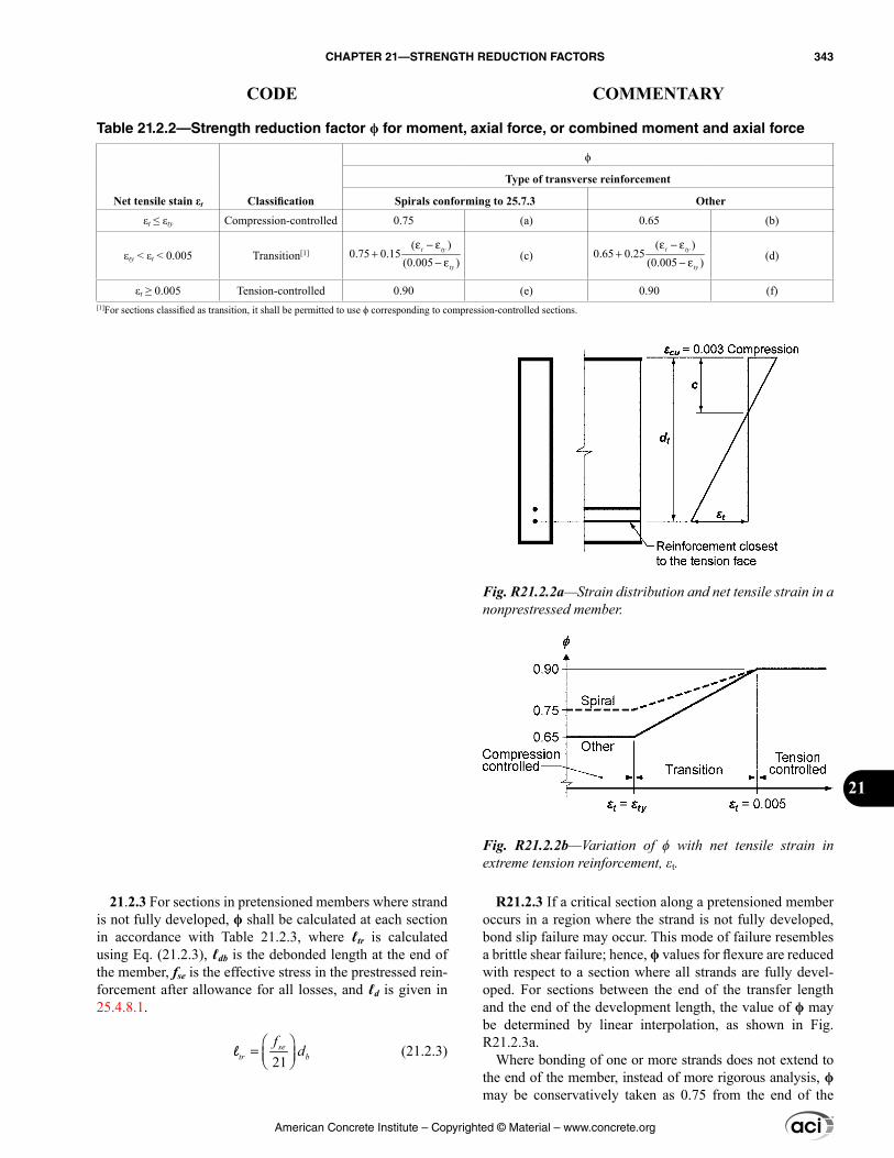
R21.2.3 If a critical section along a pretensioned member occurs in a region where the strand is not fully developed, bond slip failure may occur. This mode of failure resembles a brittle shear failure; hence, ϕ values for flexure are reduced with respect to a section where all strands are fully devel-oped. For sections between the end of the transfer length and the end of the development length, the value of ϕ may be determined by linear interpolation, as shown in Fig. R21.2.3a.
Where bonding of one or more strands does not extend to the end of the member, instead of more rigorous analysis, ϕ may be conservatively taken as 0.75 from the end of the
21.2.3 For sections in pretensioned members where strand is not fully developed, ϕ shall be calculated at each section in accordance with Table 21.2.3, where ℓtr is calculated using Eq. (21.2.3), ℓdb is the debonded length at the end of the member, fse is the effective stress in the prestressed rein-forcement after allowance for all losses, and ℓd is given in 25.4.8.1.
21
= se
tr bf
dl (21.2.3)
Table 21.2.2—Strength reduction factor ϕ for moment, axial force, or combined moment and axial force
Net tensile stain εt Classification
ϕ
Type of transverse reinforcement
Spirals conforming to 25.7.3 Other
εt ≤ εty Compression-controlled 0.75 (a) 0.65 (b)
εty < εt < 0.005 Transition[1]( )
0.75 0.15(0.005 )
t ty
ty
ε − ε+
− ε
(c)( )
0.65 0.25(0.005 )
t ty
ty
ε − ε+
− ε (d)
εt ≥ 0.005 Tension-controlled 0.90 (e) 0.90 (f)[1]For sections classified as transition, it shall be permitted to use ϕ corresponding to compression-controlled sections.
Fig. R21.2.2a—Strain distribution and net tensile strain in a nonprestressed member.
Fig. R21.2.2b—Variation of ϕ with net tensile strain in extreme tension reinforcement, εt.
American Concrete Institute – Copyrighted © Material – www.concrete.org
CHAPTER 21—STRENGTH REDUCTION FACTORS 343
CODE COMMENTARY
21
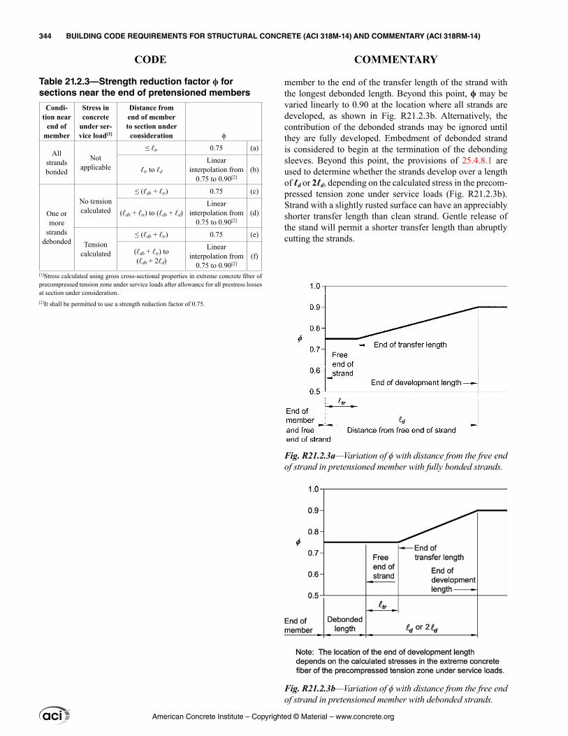
member to the end of the transfer length of the strand with the longest debonded length. Beyond this point, ϕ may be varied linearly to 0.90 at the location where all strands are developed, as shown in Fig. R21.2.3b. Alternatively, the contribution of the debonded strands may be ignored until they are fully developed. Embedment of debonded strand is considered to begin at the termination of the debonding sleeves. Beyond this point, the provisions of 25.4.8.1 are used to determine whether the strands develop over a length of ℓd or 2ℓd, depending on the calculated stress in the precom-pressed tension zone under service loads (Fig. R21.2.3b). Strand with a slightly rusted surface can have an appreciably shorter transfer length than clean strand. Gentle release of the stand will permit a shorter transfer length than abruptly cutting the strands.
Table 21.2.3—Strength reduction factor ϕ for sections near the end of pretensioned members
Condi-tion near
end of member
Stress in concrete
under ser-vice load[1]
Distance from end of member to section under
consideration ϕ
All strands bonded
Not applicable
≤ ℓtr 0.75 (a)
ℓtr to ℓd
Linear interpolation from
0.75 to 0.90[2](b)
One or more
strands debonded
No tension calculated
≤ (ℓdb + ℓtr) 0.75 (c)
(ℓdb + ℓtr) to (ℓdb + ℓd)Linear
interpolation from 0.75 to 0.90[2]
(d)
Tension calculated
≤ (ℓdb + ℓtr) 0.75 (e)
(ℓdb + ℓtr) to (ℓdb + 2ℓd)
Linear interpolation from
0.75 to 0.90[2](f)
[1]Stress calculated using gross cross-sectional properties in extreme concrete fiber of precompressed tension zone under service loads after allowance for all prestress losses at section under consideration.[2]It shall be permitted to use a strength reduction factor of 0.75.
Fig. R21.2.3a—Variation of ϕ with distance from the free end of strand in pretensioned member with fully bonded strands.
Fig. R21.2.3b—Variation of ϕ with distance from the free end of strand in pretensioned member with debonded strands.
American Concrete Institute – Copyrighted © Material – www.concrete.org
344 BUILDING CODE REQUIREMENTS FOR STRUCTURAL CONCRETE (ACI 318M-14) AND COMMENTARY (ACI 318RM-14)
CODE COMMENTARY
R21.2.4.1 This provision addresses shear-controlled members, such as low-rise walls, portions of walls between openings, or diaphragms, for which nominal shear strength is less than the shear corresponding to development of nominal flexural strength for the pertinent loading conditions.
R21.2.4.2 Short structural walls were the primary vertical elements of the lateral-force-resisting system in many of the parking structures that sustained damage during the 1994 Northridge earthquake. In some cases, walls remained essentially linear elastic, while diaphragms responded inelastically. This provision is intended to increase strength of the diaphragm and its connections in buildings for which the shear strength reduction factor for walls is 0.60, as those structures tend to have relatively high overstrength.
21.2.4 For structures that rely on elements in (a), (b), or (c) to resist earthquake effects E, the value of ϕ for shear shall be modified in accordance with 21.2.4.1 through 21.2.4.3:
(a) Special moment frames(b) Special structural walls(c) Intermediate precast structural walls in structures assigned to Seismic Design Category D, E, or F
21.2.4.1 For any member designed to resist E, ϕ for shear shall be 0.60 if the nominal shear strength of the member is less than the shear corresponding to the development of the nominal moment strength of the member. The nominal moment strength shall be calculated considering the most critical factored axial loads and including E.
21.2.4.2 For diaphragms, ϕ for shear shall not exceed the least value of ϕ for shear used for the vertical components of the primary seismic-force-resisting system.
21.2.4.3 For beam-column joints and diagonally reinforced coupling beams, ϕ for shear shall be 0.85.
American Concrete Institute – Copyrighted © Material – www.concrete.org
CHAPTER 21—STRENGTH REDUCTION FACTORS 345
CODE COMMENTARY
21

American Concrete Institute – Copyrighted © Material – www.concrete.org
346 BUILDING CODE REQUIREMENTS FOR STRUCTURAL CONCRETE (ACI 318M-14) AND COMMENTARY (ACI 318RM-14)
Notes
CHAPTER 22—SECTIONAL STRENGTH
22.1—Scope 22.1.1 This chapter shall apply to calculating nominal
strength at sections of members, including (a) through (g):
(a) Flexural strength(b) Axial strength or combined flexural and axial strength(c) One-way shear strength(d) Two-way shear strength(e) Torsional strength(f) Bearing(g) Shear friction
22.1.2 Sectional strength requirements of this chapter shall be satisfied unless the member or region of the member is designed in accordance with Chapter 23.
22.1.3 Design strength at a section shall be taken as the nominal strength multiplied by the applicable strength reduction factor ϕ given in Chapter 21.
22.2—Design assumptions for moment and axial strength
22.2.1 Equilibrium and strain compatibility
22.2.1.1 Equilibrium shall be satisfied at each section.
22.2.1.2 Strain in concrete and nonprestressed reinforce-ment shall be assumed proportional to the distance from neutral axis.
22.2.1.3 Strain in prestressed concrete and in bonded and unbonded prestressed reinforcement shall include the strain due to effective prestress.
22.2.1.4 Changes in strain for bonded prestressed rein-forcement shall be assumed proportional to the distance from neutral axis.
R22—SECTIONAL STRENGTH
R22.1—Scope R22.1.1 The provisions in this chapter apply where the
strength of the member is evaluated at critical sections.
R22.1.2 Chapter 23 provides methods for designing discontinuity regions where section-based methods do not apply.
R22.2—Design assumptions for moment and axial strength
R22.2.1 Equilibrium and strain compatibility—The flexural and axial strength of a member calculated by the strength design method of the Code requires that two basic conditions be satisfied: 1) equilibrium; and 2) compatibility of strains. Equilibrium refers to the balancing of forces acting on the cross section at nominal strength. The relation-ship between the stress and strain for the concrete and the reinforcement at nominal strength is established within the design assumptions allowed by 22.2.
R22.2.1.2 Many tests have confirmed that it is reason-able to assume a linear distribution of strain across a rein-forced concrete cross section (plane sections remain plane), even near nominal strength except in cases as described in Chapter 23.
The strain in both nonprestressed reinforcement and in concrete is assumed to be directly proportional to the distance from the neutral axis. This assumption is of primary importance in design for determining the strain and corre-sponding stress in the reinforcement.
R22.2.1.4 The change in strain for bonded prestressed reinforcement is influenced by the change in strain at the section under consideration. For unbonded prestressed rein-forcement, the change in strain is influenced by external load, reinforcement location, and boundary conditions along the length of the reinforcement. Current Code equations for
American Concrete Institute – Copyrighted © Material – www.concrete.org
BUILDING CODE REQUIREMENTS FOR STRUCTURAL CONCRETE (ACI 318M-14) AND COMMENTARY (ACI 318RM-14) 347
CODE COMMENTARY
22
calculating fps for unbonded tendons, as provided in 20.3.2.4, have been correlated with test results.
R22.2.2 Design assumptions for concrete
R22.2.2.1 The maximum concrete compressive strain at crushing of the concrete has been observed in tests of various kinds to vary from 0.003 to higher than 0.008 under special conditions. However, the strain at which strength of the member is developed is usually 0.003 to 0.004 for members of normal proportions, materials, and strength.
R22.2.2.2 The tensile strength of concrete in flexure (modulus of rupture) is a more variable property than the compressive strength and is approximately 10 to 15 percent of the compressive strength. Tensile strength of concrete in flexure is conservatively neglected in calculating the nominal flexural strength. The strength of concrete in tension, however, is important in evaluating cracking and deflections at service loads.
R22.2.2.3 At high strain levels, the stress-strain relation-ship for concrete is nonlinear (stress is not proportional to strain). As stated in 22.2.2.1, the maximum usable strain is set at 0.003 for design.
The actual distribution of concrete compressive stress within a cross section is complex and usually not known explicitly. Research has shown that the important proper-ties of the concrete stress distribution can be approximated closely using any one of several different assumptions for the shape of the stress distribution.
R22.2.2.4 For design, the Code allows the use of an equiv-alent rectangular compressive stress distribution (stress block) to replace the more detailed approximation of the concrete stress distribution.
R22.2.2.4.1 The equivalent rectangular stress distribution does not represent the actual stress distribution in the compres-sion zone at nominal strength, but does provide essentially the same nominal combined flexural and axial compressive strength as obtained in tests (Mattock et al. 1961).
R22.2.2.4.3 The values for β1 were determined experi-mentally. The lower limit of β1 is based on experimental data from beams constructed with concrete strengths greater than 55 MPa (Leslie et al. 1976; Karr et al. 1978).
22.2.2 Design assumptions for concrete
22.2.2.1 Maximum strain at the extreme concrete compres-sion fiber shall be assumed equal to 0.003.
22.2.2.2 Tensile strength of concrete shall be neglected in flexural and axial strength calculations.
22.2.2.3 The relationship between concrete compressive stress and strain shall be represented by a rectangular, trap-ezoidal, parabolic, or other shape that results in prediction of strength in substantial agreement with results of compre-hensive tests.
22.2.2.4 The equivalent rectangular concrete stress distri-bution in accordance with 22.2.2.4.1 through 22.2.2.4.3 satisfies 22.2.2.3.
22.2.2.4.1 Concrete stress of 0.85fc′ shall be assumed uniformly distributed over an equivalent compression zone bounded by edges of the cross section and a line parallel to the neutral axis located a distance a from the fiber of maximum compressive strain, as calculated by:
a = β1c (22.2.2.4.1)
22.2.2.4.2 Distance from the fiber of maximum compres-sive strain to the neutral axis, c, shall be measured perpen-dicular to the neutral axis.
22.2.2.4.3 Values of β1 shall be in accordance with Table 22.2.2.4.3.
American Concrete Institute – Copyrighted © Material – www.concrete.org
348 BUILDING CODE REQUIREMENTS FOR STRUCTURAL CONCRETE (ACI 318M-14) AND COMMENTARY (ACI 318RM-14)
CODE COMMENTARY
R22.3—Flexural strength
R22.3.3 Composite concrete members
R22.3.3.1 The scope of Chapter 22 is intended to include composite concrete flexural members. In some cases with cast-in-place concrete, separate placements of concrete may
Table 22.2.2.4.3—Values of β1 for equivalent rect-angular concrete stress distribution
fc′, MPa β1
17 ≤ fc′ ≤ 28 0.85 (a)
28 < fc′ < 550.05( 28)0.85
7−′− cf
(b)
fc′ ≥ 55 0.65 (c)
22.2.3 Design assumptions for nonprestressed reinforcement
22.2.3.1 Deformed reinforcement used to resist tensile or compressive forces shall conform to 20.2.1.
22.2.3.2 Stress-strain relationship and modulus of elas-ticity for deformed reinforcement shall be idealized in accor-dance with 20.2.2.1 and 20.2.2.2.
22.2.4 Design assumptions for prestressing reinforcement
22.2.4.1 For members with bonded prestressing rein-forcement conforming to 20.3.1, stress at nominal flexural strength, fps, shall be calculated in accordance with 20.3.2.3.
22.2.4.2 For members with unbonded prestressing rein-forcement conforming to 20.3.1, fps shall be calculated in accordance with 20.3.2.4.
22.2.4.3 If the embedded length of the prestressing strand is less than ℓd, the design strand stress shall not exceed the value given in 25.4.8.3, as modified by 25.4.8.1(b).
22.3—Flexural strength 22.3.1 General
22.3.1.1 Nominal flexural strength Mn shall be calculated in accordance with the assumptions of 22.2.
22.3.2 Prestressed concrete members
22.3.2.1 Deformed reinforcement conforming to 20.2.1, provided in conjunction with prestressed reinforcement, shall be permitted to be considered to contribute to the tensile force and be included in flexural strength calculations at a stress equal to fy.
22.3.2.2 Other nonprestressed reinforcement shall be permitted to be considered to contribute to the flexural strength if a strain compatibility analysis is performed to calculate stresses in such reinforcement.
22.3.3 Composite concrete members
22.3.3.1 Provisions of 22.3.3 apply to members constructed in separate placements but connected so that all elements resist loads as a unit.
American Concrete Institute – Copyrighted © Material – www.concrete.org
BUILDING CODE REQUIREMENTS FOR STRUCTURAL CONCRETE (ACI 318M-14) AND COMMENTARY (ACI 318RM-14) 349
CODE COMMENTARY
22

be designed to act as a unit. In these cases, the interface is designed for the loads that will be transferred across the interface. Composite structural steel-concrete beams are not covered in this chapter. Design provisions for these types of composite members are covered in AISC 360.
R22.4—Axial strength or combined flexural and axial strength
R22.4.2 Maximum axial compressive strength
R22.4.2.1 To account for accidental eccentricity, the design axial strength of a section in pure compression is limited to 80 to 85 percent of the nominal axial strength. These percentage values approximate the axial strengths at eccentricity-to-depth ratios of 0.10 and 0.05 for tied and spirally reinforced members conforming to 22.4.2.4 and 22.4.2.5, respectively. The same axial load limitation applies to both cast-in-place and precast compression members.
22.3.3.2 For calculation of Mn for composite slabs and beams, use of the entire composite section shall be permitted.
22.3.3.3 For calculation of Mn for composite slabs and beams, no distinction shall be made between shored and unshored members.
22.3.3.4 For calculation of Mn for composite members where the specified concrete compressive strength of different elements varies, properties of the individual elements shall be used in design. Alternatively, it shall be permitted to use the value of fc′ for the element that results in the most critical value of Mn.
22.4—Axial strength or combined flexural and axial strength
22.4.1 General
22.4.1.1 Nominal flexural and axial strength shall be calculated in accordance with the assumptions of 22.2.
22.4.2 Maximum axial compressive strength
22.4.2.1 Nominal axial compressive strength Pn shall not exceed Pn,max in accordance with Table 22.4.2.1, where Po is calculated by Eq. (22.4.2.2) for nonprestressed members and composite steel and concrete members, and by Eq. (22.4.2.3) for prestressed members.
Table 22.4.2.1—Maximum axial strength
MemberTransverse
reinforcement Pn,max
Nonprestressed
Ties conforming to 22.4.2.4 0.80Po (a)
Spirals conforming to 22.4.2.5 0.85Po (b)
PrestressedTies 0.80Po (c)
Spirals 0.85Po (d)
Composite steel and concrete columns in accordance with Chapter 10
All 0.85Po (e)
22.4.2.2 For nonprestressed members and composite steel and concrete members, Po shall be calculated by:
Po = 0.85fc′(Ag – Ast) + fyAst (22.4.2.2)
where Ast is the total area of nonprestressed longitudinal reinforcement.
American Concrete Institute – Copyrighted © Material – www.concrete.org
350 BUILDING CODE REQUIREMENTS FOR STRUCTURAL CONCRETE (ACI 318M-14) AND COMMENTARY (ACI 318RM-14)
CODE COMMENTARY
R22.4.2.3 The effects of prestressing on the axial strength of compression members are taken into account in Eq. (22.4.2.3). Equation (22.4.2.3) is similar to Eq. (22.4.2.2) for nonprestressed compression members. The effective area of concrete subjected to the limiting stress of 0.85fc′ is reduced by the term Apd to account for the area of ducts, sheathing, and prestressing reinforcement. A third term is added to account for the reduction of column capacity due to the prestressing force. At nominal strength, the stress in the prestressing reinforcement, fse, is decreased by 0.003Ep, where 0.003 is the assumed compressive strain at the axial capacity of the member.
R22.5—One-way shear strength R22.5.1 General
R22.5.1.1 In a member without shear reinforcement, shear is assumed to be resisted by the concrete. In a member with shear reinforcement, a portion of the shear strength is assumed to be provided by the concrete and the remainder by the shear reinforcement.
The shear strength provided by concrete, Vc, is assumed to be the same for members with and without shear reinforce-ment and is taken as the shear causing inclined cracking (Joint ACI-ASCE Committee 426 1973; MacGregor and Hanson 1969; Joint ACI-ASCE Committee 326 1962). After cracking, Vc is attributed to aggregate interlock, dowel action, and the shear transmitted across the concrete compression zone.
The shear strength is based on an average shear stress over the effective cross section, bwd.
Chapter 23 allows the use of strut-and-tie models in the shear design of any structural concrete member, or disconti-nuity region in a member. Sectional shear design procedures are acceptable in B-regions.
22.4.2.3 For prestressed members, Po shall be calculated by:
Po = 0.85fc′(Ag – Ast – Apd) + fyAst – (fse – 0.003Ep)Apt (22.4.2.3)
where Apt is the total area of prestressing reinforcement, and Apd is the total area occupied by duct, sheathing, and prestressing reinforcement; the value of fse shall be at least 0.003Ep. For grouted, post-tensioned tendons, it shall be permitted to assume Apd equals Apt.
22.4.2.4 Tie reinforcement for lateral support of longitu-dinal reinforcement in compression members shall satisfy 10.7.6.2 and 25.7.2.
22.4.2.5 Spiral reinforcement for lateral support of longi-tudinal reinforcement in compression members shall satisfy 10.7.6.3 and 25.7.3.
22.4.3 Maximum axial tensile strength
22.4.3.1 Nominal axial tensile strength of a nonpre-stressed, composite, or prestressed member, Pnt, shall not be taken greater than Pnt,max, calculated by:
Pnt,max = fyAst + (fse + ∆fp)Apt (22.4.3.1)
where (fse + ∆fp) shall not exceed fpy, and Apt is zero for nonprestressed members.
22.5—One-way shear strength 22.5.1 General
22.5.1.1 Nominal one-way shear strength at a section, Vn, shall be calculated by:
Vn = Vc + Vs (22.5.1.1)
American Concrete Institute – Copyrighted © Material – www.concrete.org
BUILDING CODE REQUIREMENTS FOR STRUCTURAL CONCRETE (ACI 318M-14) AND COMMENTARY (ACI 318RM-14) 351
CODE COMMENTARY
22
22.5.1.2 Cross-sectional dimensions shall be selected to satisfy Eq. (22.5.1.2).
( .066 )≤ φ + ′u c c wV V f b d (22.5.1.2)
22.5.1.3 For nonprestressed members, Vc shall be calcu-lated in accordance with 22.5.5, 22.5.6, or 22.5.7.
22.5.1.4 For prestressed members, Vc, Vci, and Vcw shall be calculated in accordance with 22.5.8 or 22.5.9.
22.5.1.5 For calculation of Vc, Vci, and Vcw, λ shall be in accordance with 19.2.4.
22.5.1.6 Vs shall be calculated in accordance with 22.5.10.
22.5.1.7 Effect of any openings in members shall be considered in calculating Vn.
22.5.1.8 Effect of axial tension due to creep and shrinkage in restrained members shall be considered in calculating Vc.
22.5.1.9 Effect of inclined flexural compression in vari-able depth members shall be permitted to be considered in calculating Vc.
22.5.2 Geometric assumptions
22.5.2.1 For calculation of Vc and Vs in prestressed members, d shall be taken as the distance from the extreme compression fiber to the centroid of prestressed and any nonprestressed longitudinal reinforcement but need not be taken less than 0.8h.
22.5.2.2 For calculation of Vc and Vs in solid, circular sections, d shall be permitted to be taken as 0.8 times the diameter, and bw shall be permitted to be taken as the diameter.
22.5.3 Limiting material strengths
22.5.3.1 The value of ′fc used to calculate Vc, Vci, and Vcw for one-way shear shall not exceed 8.3 MPa, unless allowed in 22.5.3.2.
R22.5.1.2 The limit on cross-sectional dimensions in 22.5.1.2 is intended to minimize the likelihood of diagonal compression failure in the concrete and limit the extent of cracking.
R22.5.1.7 Openings in the web of a member can reduce its shear strength. The effects of openings are discussed in Section 4.7 of Joint ACI-ASCE Committee 426 (1973) and in Barney et al. (1977) and Schlaich et al. (1987). Strut-and-tie models as addressed in Chapter 23 can be used to design members with openings.
R22.5.1.9 In a member of variable depth, the internal shear at any section is increased or decreased by the vertical component of the inclined flexural stresses.
R22.5.2 Geometric assumptions
R22.5.2.1 Although the value of d may vary along the span of a prestressed beam, studies (MacGregor and Hanson 1969) have shown that, for prestressed concrete members, d need not be taken less than 0.8h. The beams considered had some straight prestressed reinforcement or reinforcing bars at the bottom of the section and had stirrups that enclosed the longitudinal reinforcement.
R22.5.2.2 Shear tests of members with circular sections indicate that the effective area can be taken as the gross area of the section or as an equivalent rectangular area (Joint ACI-ASCE Committee 426 1973; Faradji and Diaz de Cossio 1965; Khalifa and Collins 1981).
Although the transverse reinforcement in a circular section may not consist of straight legs, tests indicate that Eq. (22.5.10.5.3) is conservative if d is taken as defined in 22.5.2.2 (Faradji and Diaz de Cossio 1965; Khalifa and Collins 1981).
R22.5.3 Limiting material strengths
R22.5.3.1 Because of a lack of test data and practical experience with concretes having compressive strengths greater than 70 MPa, the Code imposes a maximum value of 8.3 MPa on ′fc for use in the calculation of shear strength
American Concrete Institute – Copyrighted © Material – www.concrete.org
352 BUILDING CODE REQUIREMENTS FOR STRUCTURAL CONCRETE (ACI 318M-14) AND COMMENTARY (ACI 318RM-14)
CODE COMMENTARY
22.5.3.2 Values of ′fc greater than 8.3 MPa shall be permitted in calculating Vc, Vci, and Vcw for reinforced or prestressed concrete beams and concrete joist construction having minimum web reinforcement in accordance with 9.6.3.3 or 9.6.4.2.
22.5.3.3 The values of fy and fyt used to calculate Vs shall not exceed the limits in 20.2.2.4.
22.5.4 Composite concrete members
22.5.4.1 This section shall apply to members constructed in separate placements but connected so that all elements resist loads as a unit.
22.5.4.2 For calculation of Vn for composite members, no distinction shall be made between shored and unshored members.
22.5.4.3 For calculation of Vn for composite members where the specified concrete compressive strength, unit weight, or other properties of different elements vary, prop-erties of the individual elements shall be used in design. Alternatively, it shall be permitted to use the properties of the element that results in the most critical value of Vn.
22.5.4.4 If an entire composite member is assumed to resist vertical shear, it shall be permitted to calculate Vc assuming a monolithically cast member of the same cross-sectional shape.
22.5.4.5 If an entire composite member is assumed to resist vertical shear, it shall be permitted to calculate Vs assuming a monolithically cast member of the same cross-sectional shape if shear reinforcement is fully anchored into the interconnected elements in accordance with 25.7.
of concrete members. Exceptions to this limit are permitted in beams and joists if the transverse reinforcement satisfies the requirements in 22.5.3.2.
R22.5.3.2 Based on the beam test results in Mphonde and Frantz (1984), Elzanaty et al. (1986), Roller and Russell (1990), Johnson and Ramirez (1989), and Oczebe et al. (1999), an increase in the minimum amount of transverse reinforcement is required for high-strength concrete. These tests indicate a reduction in reserve shear strength occurs as fc′ increases in beams reinforced with transverse rein-forcement providing an effective shear stress of 0.35 MPa. By providing minimum transverse reinforcement, which increases as fc′ increases, the reduction in shear strength is offset.
R22.5.3.3 The upper limit of 420 MPa on the value of fy and fyt used in design is intended to control diagonal crack width.
R22.5.4 Composite concrete members
R22.5.4.1 The scope of Chapter 22 includes composite concrete members. In some cases with cast-in-place concrete, separate placements of concrete may be designed to act as a unit. In these cases, the interface is designed for the loads that will be transferred across the interface. Composite struc-tural steel-concrete beams are not covered in this chapter. Design provisions for such composite members are covered in AISC 360.
American Concrete Institute – Copyrighted © Material – www.concrete.org
BUILDING CODE REQUIREMENTS FOR STRUCTURAL CONCRETE (ACI 318M-14) AND COMMENTARY (ACI 318RM-14) 353
CODE COMMENTARY
22
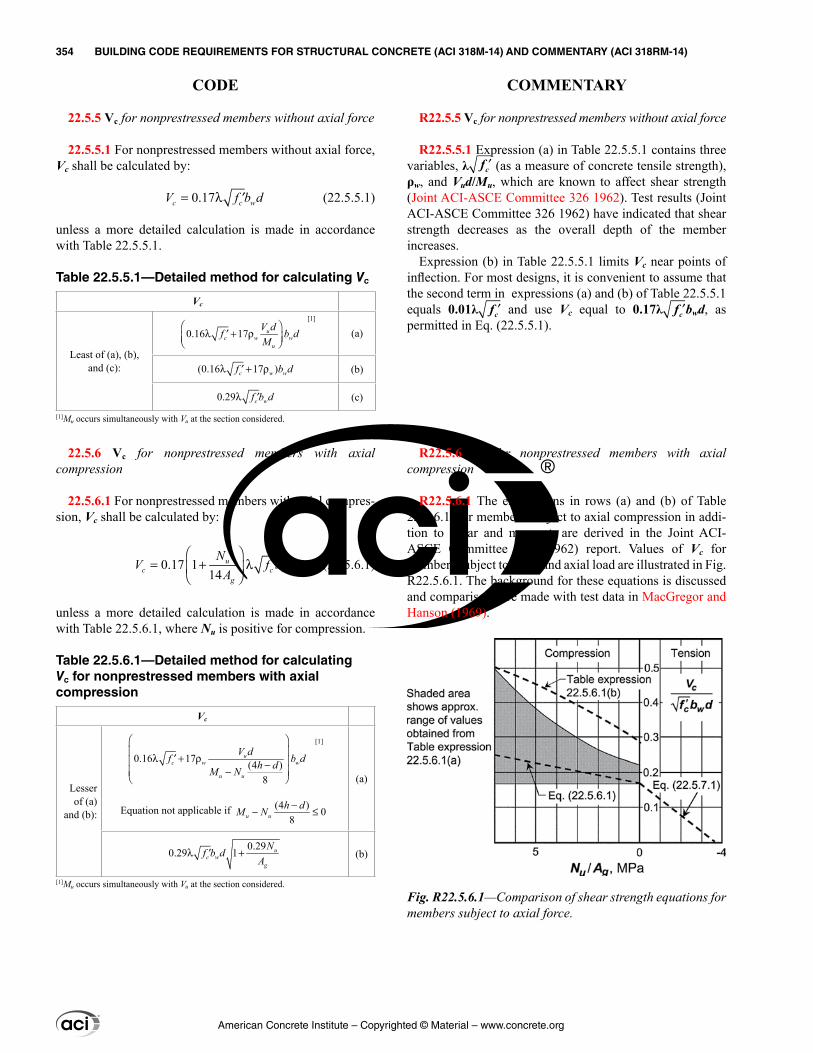
22.5.5 Vc for nonprestressed members without axial force
22.5.5.1 For nonprestressed members without axial force, Vc shall be calculated by:
0.17= λ ′c c wV f b d (22.5.5.1)
unless a more detailed calculation is made in accordance with Table 22.5.5.1.
Table 22.5.5.1—Detailed method for calculating Vc
Vc
Least of (a), (b), and (c):
0.16 17
λ + ρ′ u
c w wu
V df b dM
[1]
(a)
(0.16 17 )λ + ρ′c w wf b d (b)
0.29λ ′c wf b d (c)
[1]Mu occurs simultaneously with Vu at the section considered.
22.5.6 Vc for nonprestressed members with axial compression
22.5.6.1 For nonprestressed members with axial compres-sion, Vc shall be calculated by:
0.17 114
= + λ ′
u
c c wg
NV f b d
A (22.5.6.1)
unless a more detailed calculation is made in accordance with Table 22.5.6.1, where Nu is positive for compression.
Table 22.5.6.1—Detailed method for calculating Vc for nonprestressed members with axial compression
Vc
Lesser of (a)
and (b):
0.16 17 (4 )8
λ + ρ′ − −
uc w w
u u
V df b dh dM N
[1]
Equation not applicable if (4 ) 08u u
h dM N −− ≤
(a)
0.290.29 1λ +′ uc w
g
Nf b dA (b)
[1]Mu occurs simultaneously with Vu at the section considered.
R22.5.5 Vc for nonprestressed members without axial force
R22.5.5.1 Expression (a) in Table 22.5.5.1 contains three variables, λ ′fc (as a measure of concrete tensile strength), ρw, and Vud/Mu, which are known to affect shear strength (Joint ACI-ASCE Committee 326 1962). Test results (Joint ACI-ASCE Committee 326 1962) have indicated that shear strength decreases as the overall depth of the member increases.
Expression (b) in Table 22.5.5.1 limits Vc near points of inflection. For most designs, it is convenient to assume that the second term in expressions (a) and (b) of Table 22.5.5.1 equals 0.01λ ′fc and use Vc equal to 0.17λ ′fc bwd, as permitted in Eq. (22.5.5.1).
R22.5.6 Vc for nonprestressed members with axial compression
R22.5.6.1 The expressions in rows (a) and (b) of Table 22.5.6.1, for members subject to axial compression in addi-tion to shear and moment, are derived in the Joint ACI-ASCE Committee 326 (1962) report. Values of Vc for members subject to shear and axial load are illustrated in Fig. R22.5.6.1. The background for these equations is discussed and comparisons are made with test data in MacGregor and Hanson (1969).
Fig. R22.5.6.1—Comparison of shear strength equations for members subject to axial force.
American Concrete Institute – Copyrighted © Material – www.concrete.org
354 BUILDING CODE REQUIREMENTS FOR STRUCTURAL CONCRETE (ACI 318M-14) AND COMMENTARY (ACI 318RM-14)
CODE COMMENTARY
22.5.7 Vc for nonprestressed members with significant axial tension
22.5.7.1 For nonprestressed members with significant axial tension, Vc shall be calculated by:
0.17 13.5
= + λ ′
u
c c wg
NV f b d
A (22.5.7.1)
where Nu is negative for tension, and Vc shall not be less than zero.
22.5.8 Vc for prestressed members
22.5.8.1 This section shall apply to the calculation of Vc for post-tensioned and pretensioned members in regions where the effective force in the prestressed reinforcement is fully transferred to the concrete. For regions of preten-sioned members where the effective force in the prestressed reinforcement is not fully transferred to the concrete, 22.5.9 shall govern the calculation of Vc.
22.5.8.2 For prestressed flexural members with Apsfse ≥ 0.4(Apsfpu + Asfy), Vc shall be calculated in accordance with Table 22.5.8.2, but need not be less than the value calcu-lated by Eq. (22.5.5.1). Alternatively, it shall be permitted to calculate Vc in accordance with 22.5.8.3.
Table 22.5.8.2—Approximate method for calculating Vc
Vc
Least of (a), (b), and (c):
0.05 4.8
λ +′ u p
c wu
V df b d
M
[1]
(a)
(0.05 4.8)λ +′c wf b d (b)
0.42λ ′c wf b d (c)
[1]Mu occurs simultaneously with Vu at the section considered.
R22.5.7 Vc for nonprestressed members with significant axial tension
R22.5.7.1 The term “significant” is used to recognize that judgment is required in deciding whether axial tension needs to be considered. Axial tension often occurs due to volume changes, but the levels may not be detrimental to the perfor-mance of a structure with adequate expansion joints and minimum reinforcement. It may be desirable to design shear reinforcement to resist the total shear if there is uncertainty about the magnitude of axial tension.
R22.5.8 Vc for prestressed members
R22.5.8.2 This provision offers a simple means of calcu-lating Vc for prestressed concrete beams (MacGregor and Hanson 1969). This provision may be applied to beams having prestressed reinforcement only, or to members rein-forced with a combination of prestressed and nonprestressed reinforcement. Expression (a) in Table 22.5.8.2 is most applicable to members subject to uniform loading.
In applying the expression in row (a) to simply-supported members subject to uniform loads, Eq. (R22.5.8.2) can be used:
( 2 )( )
u p p
u
V d d xM x x
−=
−l
l (R22.5.8.2)
where ℓ is the span length, and x is the distance from the section being investigated to the support. For concrete with fc′ equal to 35 MPa, Vc from 22.5.8.2 varies, as shown in Fig. R22.5.8.2. Design aids based on this equation are given in ASCE Joint Committee (1940).
American Concrete Institute – Copyrighted © Material – www.concrete.org
BUILDING CODE REQUIREMENTS FOR STRUCTURAL CONCRETE (ACI 318M-14) AND COMMENTARY (ACI 318RM-14) 355
CODE COMMENTARY
22
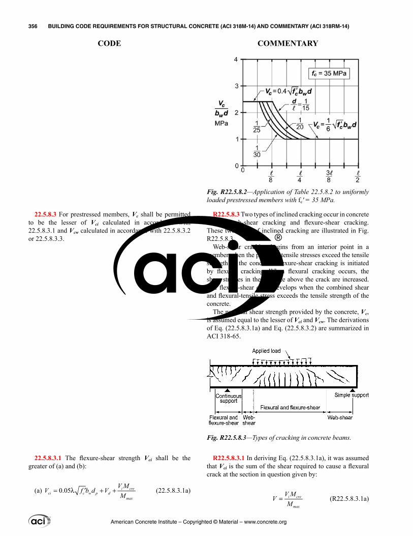
22.5.8.3 For prestressed members, Vc shall be permitted to be the lesser of Vci calculated in accordance with 22.5.8.3.1 and Vcw calculated in accordance with 22.5.8.3.2 or 22.5.8.3.3.
22.5.8.3.1 The flexure-shear strength Vci shall be the greater of (a) and (b):
(a) 0.05= λ + +′ i creci c w p d
max
V MV f b d V
M (22.5.8.3.1a)
R22.5.8.3 Two types of inclined cracking occur in concrete beams: web-shear cracking and flexure-shear cracking. These two types of inclined cracking are illustrated in Fig. R22.5.8.3.
Web-shear cracking begins from an interior point in a member when the principal tensile stresses exceed the tensile strength of the concrete. Flexure-shear cracking is initiated by flexural cracking. When flexural cracking occurs, the shear stresses in the concrete above the crack are increased. The flexure-shear crack develops when the combined shear and flexural-tensile stress exceeds the tensile strength of the concrete.
The nominal shear strength provided by the concrete, Vc, is assumed equal to the lesser of Vci and Vcw. The derivations of Eq. (22.5.8.3.1a) and Eq. (22.5.8.3.2) are summarized in ACI 318-65.
R22.5.8.3.1 In deriving Eq. (22.5.8.3.1a), it was assumed that Vci is the sum of the shear required to cause a flexural crack at the section in question given by:
i cre
max
V MV
M= (R22.5.8.3.1a)
Fig. R22.5.8.3—Types of cracking in concrete beams.
Fig. R22.5.8.2—Application of Table 22.5.8.2 to uniformly loaded prestressed members with fc′ = 35 MPa.
American Concrete Institute – Copyrighted © Material – www.concrete.org
356 BUILDING CODE REQUIREMENTS FOR STRUCTURAL CONCRETE (ACI 318M-14) AND COMMENTARY (ACI 318RM-14)
CODE COMMENTARY
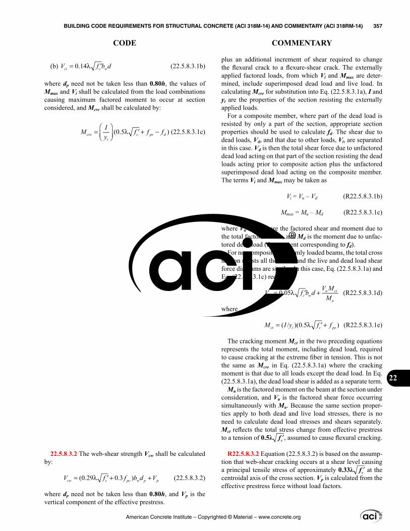
plus an additional increment of shear required to change the flexural crack to a flexure-shear crack. The externally applied factored loads, from which Vi and Mmax are deter-mined, include superimposed dead load and live load. In calculating Mcre for substitution into Eq. (22.5.8.3.1a), I and yt are the properties of the section resisting the externally applied loads.
For a composite member, where part of the dead load is resisted by only a part of the section, appropriate section properties should be used to calculate fd. The shear due to dead loads, Vd, and that due to other loads, Vi, are separated in this case. Vd is then the total shear force due to unfactored dead load acting on that part of the section resisting the dead loads acting prior to composite action plus the unfactored superimposed dead load acting on the composite member. The terms Vi and Mmax may be taken as
Vi = Vu – Vd (R22.5.8.3.1b)
Mmax = Mu – Md (R22.5.8.3.1c)
where Vu and Mu are the factored shear and moment due to the total factored loads, and Md is the moment due to unfac-tored dead load (the moment corresponding to fd).
For noncomposite, uniformly loaded beams, the total cross section resists all the shear, and the live and dead load shear force diagrams are similar. In this case, Eq. (22.5.8.3.1a) and Eq. (22.5.8.3.1c) reduce to
0.05= λ +′ u ctci c w
u
V MV f b d
M (R22.5.8.3.1d)
where
( / )(0.5 )= λ +′ct t c peM I y f f (R22.5.8.3.1e)
The cracking moment Mct in the two preceding equations represents the total moment, including dead load, required to cause cracking at the extreme fiber in tension. This is not the same as Mcre in Eq. (22.5.8.3.1a) where the cracking moment is that due to all loads except the dead load. In Eq. (22.5.8.3.1a), the dead load shear is added as a separate term.
Mu is the factored moment on the beam at the section under consideration, and Vu is the factored shear force occurring simultaneously with Mu. Because the same section proper-ties apply to both dead and live load stresses, there is no need to calculate dead load stresses and shears separately. Mct reflects the total stress change from effective prestress to a tension of 0.5λ ′fc , assumed to cause flexural cracking.
R22.5.8.3.2 Equation (22.5.8.3.2) is based on the assump-tion that web-shear cracking occurs at a shear level causing a principal tensile stress of approximately 0.33λ ′fc at the centroidal axis of the cross section. Vp is calculated from the effective prestress force without load factors.
(b) 0.14= λ ′ci c wV f b d (22.5.8.3.1b)
where dp need not be taken less than 0.80h, the values of Mmax and Vi shall be calculated from the load combinations causing maximum factored moment to occur at section considered, and Mcre shall be calculated by:
(0.5 )
= λ + −′ cre c pe dt
IM f f fy
(22.5.8.3.1c)
22.5.8.3.2 The web-shear strength Vcw shall be calculated by:
(0.29 0.3 )= λ + +′cw c pc w p pV f f b d V (22.5.8.3.2)
where dp need not be taken less than 0.80h, and Vp is the vertical component of the effective prestress.
American Concrete Institute – Copyrighted © Material – www.concrete.org
BUILDING CODE REQUIREMENTS FOR STRUCTURAL CONCRETE (ACI 318M-14) AND COMMENTARY (ACI 318RM-14) 357
CODE COMMENTARY
22
R22.5.9 Vc for pretensioned members in regions of reduced prestress force—The effect of the reduced prestress near the ends of pretensioned beams on the shear strength should be taken into account. Provisions 22.5.9.2 and 22.5.9.3 relate to the reduced shear strength at sections within the transfer length of prestressed reinforcement when bonding of prestressing reinforcement extends to the end of the member. Provisions 22.5.9.4 and 22.5.9.5 relate to the reduced shear strength at sections within the length over which some of the prestressed reinforcement is not bonded to the concrete, or within the transfer length of the prestressed reinforcement for which bonding does not extend to the end of the beam.
22.5.8.3.3 As an alternative to 22.5.8.3.2, it shall be permitted to calculate Vcw as the shear force corresponding to dead load plus live load that results in a principal tensile stress of 0.33λ ′fc at location (a) or (b):
(a) Where the centroidal axis of the prestressed cross section is in the web, the principal tensile stress shall be calculated at the centroidal axis.(b) Where the centroidal axis of the prestressed cross section is in the flange, the principal tensile stress shall be calculated at the intersection of the flange and the web.
22.5.8.3.4 In composite members, the principal tensile stress in 22.5.8.3.3 shall be calculated using the cross section that resists live load.
22.5.9 Vc for pretensioned members in regions of reduced prestress force
22.5.9.1 When calculating Vc, the transfer length of prestressed reinforcement, ℓtr, shall be assumed to be 50db for strand and 100db for wire.
22.5.9.2 If bonding of strands extends to the end of the member, the effective prestress force shall be assumed to vary linearly from zero at the end of the prestressed rein-forcement to a maximum at a distance ℓtr from the end of the prestressed reinforcement.
22.5.9.3 At locations corresponding to a reduced effective prestress force in 22.5.9.2, Vc shall be calculated in accor-dance with (a) through (c):
(a) The reduced effective prestress force shall be used to determine the applicability of 22.5.8.2.(b) The reduced effective prestress force shall be used to calculate Vcw in 22.5.8.3.(c) The value of Vc calculated using 22.5.8.2 shall not exceed the value of Vcw calculated using the reduced effective prestress force.
22.5.9.4 If bonding of strands does not extend to the end of the member, the effective prestress force shall be assumed to vary linearly from zero at the point where bonding commences to a maximum at a distance ℓtr from that point.
22.5.9.5 At locations corresponding to a reduced effective prestress force according to 22.5.9.4, Vc shall be calculated in accordance with (a) through (c):
(a) The reduced effective prestress force shall be used to determine the applicability of 22.5.8.2.(b) The reduced effective prestress force shall be used to calculate Vc in accordance with 22.5.8.3.
American Concrete Institute – Copyrighted © Material – www.concrete.org
358 BUILDING CODE REQUIREMENTS FOR STRUCTURAL CONCRETE (ACI 318M-14) AND COMMENTARY (ACI 318RM-14)
CODE COMMENTARY
R22.5.10 One-way shear reinforcement
R22.5.10.2 Provisions of 22.5.10.5 apply to all types of transverse reinforcement, including stirrups, ties, hoops, crossties, and spirals.
R22.5.10.5 One-way shear strength provided by trans-verse reinforcement—Design of shear reinforcement is based on a modified truss analogy. In the truss analogy, the force in vertical ties is resisted by shear reinforcement. However, considerable research on both nonprestressed and prestressed members has indicated that shear reinforce-ment needs to be designed to resist only the shear exceeding that which causes inclined cracking, provided the diagonal members in the truss are assumed to be inclined at 45 degrees. The concrete is assumed to contribute to the shear capacity through resistance across the concrete compressive zone, aggregate interlock, and dowel action in an amount equivalent to that which caused incline cracking.
Equations (22.5.10.5.3), (22.5.10.5.4), and (22.5.10.6.2a) are presented in terms of nominal shear strength provided by shear reinforcement Vs. Where shear reinforcement perpen-dicular to the axis of the member is used, the required area of shear reinforcement, Av, and its spacing, s, are calculated by
( )v u c
yt
A V Vs f d
− φ=
φ (R22.5.10.5)
Research (Anderson and Ramirez 1989; Leonhardt and Walther 1964) has shown that shear behavior of wide beams with substantial flexural reinforcement is improved if the transverse spacing of stirrup legs across the section is reduced.
(c) The value of Vc calculated using 22.5.8.2 shall not exceed the value of Vcw calculated using the reduced effective prestress force.
22.5.10 One-way shear reinforcement
22.5.10.1 At each section where Vu > ϕVc, transverse reinforcement shall be provided such that Eq. (22.5.10.1) is satisfied.
us c
VV V≥ −
φ (22.5.10.1)
22.5.10.2 For one-way members reinforced with trans-verse reinforcement, Vs shall be calculated in accordance with 22.5.10.5.
22.5.10.3 For one-way members reinforced with bent-up longitudinal bars, Vs shall be calculated in accordance with 22.5.10.6.
22.5.10.4 If more than one type of shear reinforcement is provided to reinforce the same portion of a member, Vs shall be the sum of the Vs values for the various types of shear reinforcement.
22.5.10.5 One-way shear strength provided by transverse reinforcement
22.5.10.5.1 In nonprestressed and prestressed members, shear reinforcement satisfying (a), (b), or (c) shall be permitted:
(a) Stirrups, ties, or hoops perpendicular to longitudinal axis of member(b) Welded wire reinforcement with wires located perpen-dicular to longitudinal axis of member(c) Spiral reinforcement
22.5.10.5.2 Inclined stirrups making an angle of at least 45 degrees with the longitudinal axis of the member and crossing the plane of the potential shear crack shall be permitted to be used as shear reinforcement in nonprestressed members.
22.5.10.5.3 Vs for shear reinforcement in 22.5.10.5.1 shall be calculated by:
v yts
A f dV
s= (22.5.10.5.3)
where s is the spiral pitch or the longitudinal spacing of the shear reinforcement, and Av is given in 22.5.10.5.5 or 22.5.10.5.6.
American Concrete Institute – Copyrighted © Material – www.concrete.org
BUILDING CODE REQUIREMENTS FOR STRUCTURAL CONCRETE (ACI 318M-14) AND COMMENTARY (ACI 318RM-14) 359
CODE COMMENTARY
22
R22.5.10.5.4 To be effective, it is critical that inclined stir-rups cross potential shear cracks. If the inclined stirrups are generally oriented parallel to the potential shear cracks, the stirrups provide no shear strength.
R22.5.10.5.6 Although the transverse reinforcement in a circular section may not consist of straight legs, tests indicate that Eq. (22.5.10.5.3) is conservative if d is taken as defined in 22.5.2.2 (Faradji and Diaz de Cossio 1965; Khalifa and Collins 1981).
R22.5.10.6 One-way shear strength provided by bent-up longitudinal bars—To be effective, it is critical that the inclined portion of the bent-up longitudinal bar cross poten-tial shear cracks. If the inclined bars are generally oriented parallel to the potential shear cracks, the bars provide no shear strength.
R22.6—Two-way shear strength Factored shear stress in two-way members due to shear
and moment transfer is calculated in accordance with the requirements of 8.4.4. Section 22.6 provides requirements for determining nominal shear strength, either without shear reinforcement or with shear reinforcement in the form of stirrups, headed shear studs, or shearheads. Factored shear demand and strength are calculated in terms of stress,
22.5.10.5.4 Vs for shear reinforcement in 22.5.10.5.2 shall be calculated by:
(sin cos )v yt
s
A f dV
sα + α
= (22.5.10.5.4)
where α is the angle between the inclined stirrups and the longitudinal axis of the member, s is measured parallel to the longitudinal reinforcement, and Av is given in 22.5.10.5.5.
22.5.10.5.5 For each rectangular tie, stirrup, hoop, or crosstie, Av shall be the effective area of all bar legs or wires within spacing s.
22.5.10.5.6 For each circular tie or spiral, Av shall be two times the area of the bar or wire within spacing s.
22.5.10.6 One-way shear strength provided by bent-up longitudinal bars
22.5.10.6.1 The center three-fourths of the inclined portion of bent-up longitudinal bars shall be permitted to be used as shear reinforcement in nonprestressed members if the angle α between the bent-up bars and the longitudinal axis of the member is at least 30 degrees.
22.5.10.6.2 If shear reinforcement consists of a single bar or a single group of parallel bars having an area Av, all bent the same distance from the support, Vs shall be the lesser of (a) and (b):
(a) Vs = Avfysinα (22.5.10.6.2a)
(b) 0.25= ′s c wV f b d (22.5.10.6.2b)
where α is the angle between bent-up reinforcement and longitudinal axis of the member.
22.5.10.6.3 If shear reinforcement consists of a series of parallel bent-up bars or groups of parallel bent-up bars at different distances from the support, Vs shall be calculated by Eq. (22.5.10.5.4).
22.6—Two-way shear strength
American Concrete Institute – Copyrighted © Material – www.concrete.org
360 BUILDING CODE REQUIREMENTS FOR STRUCTURAL CONCRETE (ACI 318M-14) AND COMMENTARY (ACI 318RM-14)
CODE COMMENTARY
permitting superposition of effects from direct shear and moment transfer.
R22.6.1 General
R22.6.1.4 The critical section perimeter bo is defined in 22.6.4.
R22.6.3 Limiting material strengths
R22.6.3.1 There are limited test data on the two-way shear strength of high-strength concrete slabs. Until more experience is obtained for two-way slabs constructed with concretes that have compressive strengths greater than
22.6.1 General
22.6.1.1 Provisions 22.6.1 through 22.6.8 apply to the nominal shear strength of two-way members with and without shear reinforcement. Where structural steel I- or channel-shaped sections are used as shearheads, two-way members shall be designed for shear in accordance with 22.6.9.
22.6.1.2 Nominal shear strength for two-way members without shear reinforcement shall be calculated by
vn = vc (22.6.1.2)
22.6.1.3 Nominal shear strength for two-way members with shear reinforcement other than shearheads shall be calculated by
vn = vc + vs (22.6.1.3)
22.6.1.4 Two-way shear shall be resisted by a section with a depth d and an assumed critical perimeter bo as defined in 22.6.4.
22.6.1.5 vc for two-way shear shall be calculated in accor-dance with 22.6.5. For two-way members with shear rein-forcement, vc shall not exceed the limits in 22.6.6.1.
22.6.1.6 For calculation of vc, λ shall be in accordance with 19.2.4.
22.6.1.7 For two-way members reinforced with single- or multiple-leg stirrups, vs shall be calculated in accordance with 22.6.7.
22.6.1.8 For two-way members reinforced with headed shear stud reinforcement, vs shall be calculated in accor-dance with 22.6.8.
22.6.2 Effective depth
22.6.2.1 For calculation of vc and vs for two-way shear, d shall be the average of the effective depths in the two orthog-onal directions.
22.6.2.2 For prestressed, two-way members, d need not be taken less than 0.8h.
22.6.3 Limiting material strengths
22.6.3.1 The value of ′fc used to calculate vc for two-way shear shall not exceed 8.3 MPa.
American Concrete Institute – Copyrighted © Material – www.concrete.org
BUILDING CODE REQUIREMENTS FOR STRUCTURAL CONCRETE (ACI 318M-14) AND COMMENTARY (ACI 318RM-14) 361
CODE COMMENTARY
22
70 MPa, it is prudent to limit ′fc to 8.3 MPa for the calcu-lation of shear strength.
R22.6.3.2 The upper limit of 420 MPa on the value of fyt used in design is intended to control cracking.
R22.6.4 Critical sections for two-way members—The critical section defined in 22.6.4.1(a) for shear in slabs and footings subjected to bending in two directions follows the perimeter at the edge of the loaded area (Joint ACI-ASCE Committee 326 1962). Loaded area for shear in two-way slabs and footings includes columns, concentrated loads, and reaction areas. An idealized critical section located a distance d/2 from the periphery of the loaded area is considered.
For members of uniform thickness without shear rein-forcement, it is sufficient to check shear using one section. For slabs with changes in thickness or with shear reinforce-ment, it is necessary to check shear at multiple sections as defined in 22.6.4.1(a) and (b) and 22.6.4.2.
For columns near an edge or corner, the critical perimeter may extend to the edge of the slab.
R22.6.4.2 For two-way members with stirrup or headed stud shear reinforcement, it is required to check shear stress in concrete at a critical section located a distance d/2 beyond the point where shear reinforcement is discontinued. Calcu-lated shear stress at this section must not exceed the limits given in expressions (b) and (d) in Table 22.6.6.1. The shape of this outermost critical section should correspond to the minimum value of bo, as depicted in Fig. R22.6.4.2a, b, and c. Note that these figures depict slabs reinforced with stir-rups. The shape of the outermost critical section is similar for slabs with headed shear reinforcement. The square or rectangular critical sections described in 22.6.4.1.1 will not result in the minimum value of bo for the cases depicted in these figures. Additional critical section checks are required at a distance d/2 beyond any point where variations in shear reinforcement occur, such as changes in size, spacing, or configuration.
22.6.3.2 The value of fyt used to calculate vs shall not exceed the limits in 20.2.2.4.
22.6.4 Critical sections for two-way members
22.6.4.1 For two-way shear, critical sections shall be located so that the perimeter bo is a minimum but need not be closer than d/2 to (a) and (b):
(a) Edges or corners of columns, concentrated loads, or reaction areas
(b) Changes in slab or footing thickness, such as edges of capitals, drop panels, or shear caps
22.6.4.1.1 For square or rectangular columns, concentrated loads, or reaction areas, critical sections for two-way shear in accordance with 22.6.4.1(a) and (b) shall be permitted to be defined assuming straight sides.
22.6.4.1.2 For a circular or regular polygon-shaped column, critical sections for two-way shear in accordance with 22.6.4.1(a) and (b) shall be permitted to be defined assuming a square column of equivalent area.
22.6.4.2 For two-way members reinforced with headed shear reinforcement or single- or multi-leg stirrups, a critical section with perimeter bo located d/2 beyond the outermost peripheral line of shear reinforcement shall also be consid-ered. The shape of this critical section shall be a polygon selected to minimize bo.
American Concrete Institute – Copyrighted © Material – www.concrete.org
362 BUILDING CODE REQUIREMENTS FOR STRUCTURAL CONCRETE (ACI 318M-14) AND COMMENTARY (ACI 318RM-14)
CODE COMMENTARY
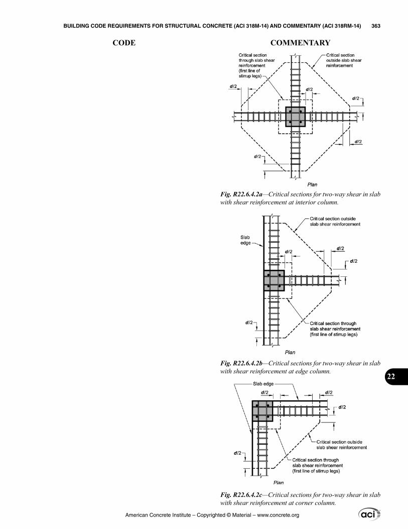
Fig. R22.6.4.2a—Critical sections for two-way shear in slab with shear reinforcement at interior column.
Fig. R22.6.4.2b—Critical sections for two-way shear in slab with shear reinforcement at edge column.
Fig. R22.6.4.2c—Critical sections for two-way shear in slab with shear reinforcement at corner column.
American Concrete Institute – Copyrighted © Material – www.concrete.org
BUILDING CODE REQUIREMENTS FOR STRUCTURAL CONCRETE (ACI 318M-14) AND COMMENTARY (ACI 318RM-14) 363
CODE COMMENTARY
22
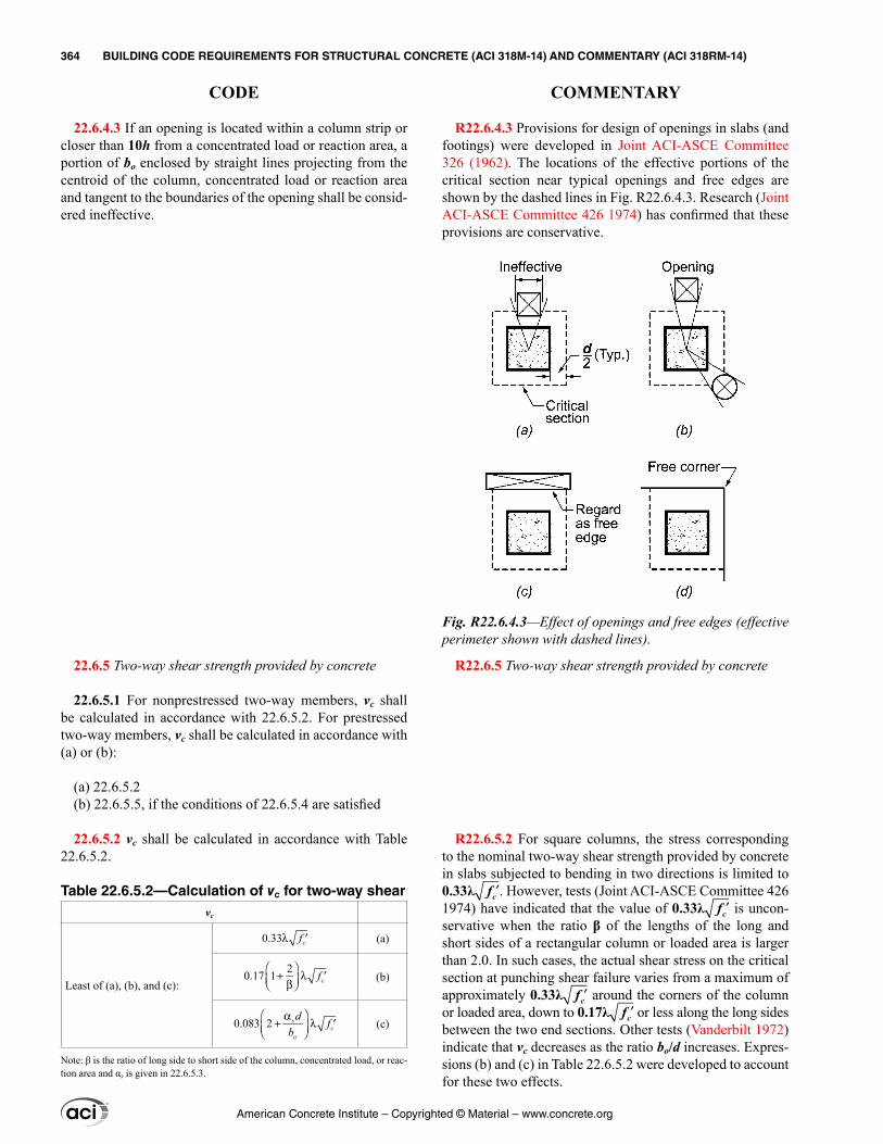
R22.6.4.3 Provisions for design of openings in slabs (and footings) were developed in Joint ACI-ASCE Committee 326 (1962). The locations of the effective portions of the critical section near typical openings and free edges are shown by the dashed lines in Fig. R22.6.4.3. Research (Joint ACI-ASCE Committee 426 1974) has confirmed that these provisions are conservative.
R22.6.5 Two-way shear strength provided by concrete
R22.6.5.2 For square columns, the stress corresponding to the nominal two-way shear strength provided by concrete in slabs subjected to bending in two directions is limited to 0.33λ ′fc . However, tests (Joint ACI-ASCE Committee 426 1974) have indicated that the value of 0.33λ ′fc is uncon-servative when the ratio β of the lengths of the long and short sides of a rectangular column or loaded area is larger than 2.0. In such cases, the actual shear stress on the critical section at punching shear failure varies from a maximum of approximately 0.33λ ′fc around the corners of the column or loaded area, down to 0.17λ ′fc or less along the long sides between the two end sections. Other tests (Vanderbilt 1972) indicate that vc decreases as the ratio bo/d increases. Expres-sions (b) and (c) in Table 22.6.5.2 were developed to account for these two effects.
22.6.4.3 If an opening is located within a column strip or closer than 10h from a concentrated load or reaction area, a portion of bo enclosed by straight lines projecting from the centroid of the column, concentrated load or reaction area and tangent to the boundaries of the opening shall be consid-ered ineffective.
22.6.5 Two-way shear strength provided by concrete
22.6.5.1 For nonprestressed two-way members, vc shall be calculated in accordance with 22.6.5.2. For prestressed two-way members, vc shall be calculated in accordance with (a) or (b):
(a) 22.6.5.2(b) 22.6.5.5, if the conditions of 22.6.5.4 are satisfied
22.6.5.2 vc shall be calculated in accordance with Table 22.6.5.2.
Table 22.6.5.2—Calculation of vc for two-way shearvc
Least of (a), (b), and (c):
0.33λ ′cf (a)
20.17 1
+ λ ′ β cf
(b)
0.083 2 α+ λ ′
sc
o
d fb
(c)
Note: β is the ratio of long side to short side of the column, concentrated load, or reac-tion area and αs is given in 22.6.5.3.
Fig. R22.6.4.3—Effect of openings and free edges (effective perimeter shown with dashed lines).
American Concrete Institute – Copyrighted © Material – www.concrete.org
364 BUILDING CODE REQUIREMENTS FOR STRUCTURAL CONCRETE (ACI 318M-14) AND COMMENTARY (ACI 318RM-14)
CODE COMMENTARY
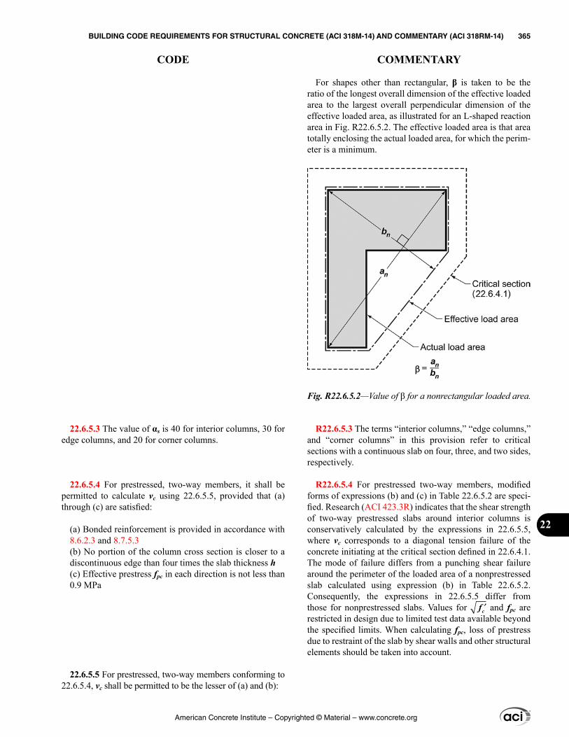
For shapes other than rectangular, β is taken to be the ratio of the longest overall dimension of the effective loaded area to the largest overall perpendicular dimension of the effective loaded area, as illustrated for an L-shaped reaction area in Fig. R22.6.5.2. The effective loaded area is that area totally enclosing the actual loaded area, for which the perim-eter is a minimum.
R22.6.5.3 The terms “interior columns,” “edge columns,” and “corner columns” in this provision refer to critical sections with a continuous slab on four, three, and two sides, respectively.
R22.6.5.4 For prestressed two-way members, modified forms of expressions (b) and (c) in Table 22.6.5.2 are speci-fied. Research (ACI 423.3R) indicates that the shear strength of two-way prestressed slabs around interior columns is conservatively calculated by the expressions in 22.6.5.5, where vc corresponds to a diagonal tension failure of the concrete initiating at the critical section defined in 22.6.4.1. The mode of failure differs from a punching shear failure around the perimeter of the loaded area of a nonprestressed slab calculated using expression (b) in Table 22.6.5.2. Consequently, the expressions in 22.6.5.5 differ from those for nonprestressed slabs. Values for ′fc and fpc are restricted in design due to limited test data available beyond the specified limits. When calculating fpc, loss of prestress due to restraint of the slab by shear walls and other structural elements should be taken into account.
22.6.5.3 The value of αs is 40 for interior columns, 30 for edge columns, and 20 for corner columns.
22.6.5.4 For prestressed, two-way members, it shall be permitted to calculate vc using 22.6.5.5, provided that (a) through (c) are satisfied:
(a) Bonded reinforcement is provided in accordance with 8.6.2.3 and 8.7.5.3(b) No portion of the column cross section is closer to a discontinuous edge than four times the slab thickness h(c) Effective prestress fpc in each direction is not less than 0.9 MPa
22.6.5.5 For prestressed, two-way members conforming to 22.6.5.4, vc shall be permitted to be the lesser of (a) and (b):
Fig. R22.6.5.2—Value of β for a nonrectangular loaded area.
American Concrete Institute – Copyrighted © Material – www.concrete.org
BUILDING CODE REQUIREMENTS FOR STRUCTURAL CONCRETE (ACI 318M-14) AND COMMENTARY (ACI 318RM-14) 365
CODE COMMENTARY
22
R22.6.6 Maximum shear for two-way members with shear reinforcement—Critical sections for two-way members with shear reinforcement are defined in 22.6.4.1 for the sections adjacent to the column, concentrated load, or reaction area, and 22.6.4.2 for the section located just beyond the outermost peripheral line of stirrup or headed shear stud reinforcement. Values of maximum vc for these critical sections are given in Table 22.6.6.1. Limiting values of vu for the critical sections defined in 22.6.4.1 are given in Table 22.6.6.2.
The maximum vc and limiting value of vu at the innermost critical section (defined in 22.6.4.1) are higher where headed shear stud reinforcement is provided than the case where stirrups are provided (refer to R12.7.7). Maximum vc values at the critical sections defined in 22.6.4.2 beyond the outer-most peripheral line of shear reinforcement are independent of the type of shear reinforcement provided.
R22.6.7 Two-way shear strength provided by single- or multiple-leg stirrups
R22.6.7.2 Because shear stresses are used for two-way shear in this chapter, shear strength provided by transverse
(a) 0.29 0.3= λ + +′ pc c pc
o
Vv f f
b d (22.6.5.5a)
(b) 0.083 1.5 0.3 α
= + λ + +′ ps
c c pco o
Vdv f f
b b d (22.6.5.5b)
where αs is given in 22.6.5.3; the value of fpc is the average of fpc in the two directions and shall not exceed 3.5 MPa; Vp is the vertical component of all effective prestress forces crossing the critical section; and the value of ′fc shall not exceed 5.8 MPa.
22.6.6 Maximum shear for two-way members with shear reinforcement
22.6.6.1 For two-way members with shear reinforcement, the value of vc calculated at critical sections shall not exceed the limits in Table 22.6.6.1.
Table 22.6.6.1—Maximum vc for two-way members with shear reinforcement
Type of shear reinforcement
Maximum vc at critical sections
defined in 22.6.4.1
Maximum vc at critical section
defined in 22.6.4.2
Stirrups 0.17λ ′fc (a) 0.17λ ′fc (b)
Headed shear stud
reinforcement0.25λ ′fc (c) 0.17λ ′fc (d)
22.6.6.2 For two-way members with shear reinforcement, effective depth shall be selected such that vu calculated at critical sections does not exceed the values in Table 22.6.6.2
Table 22.6.6.2—Maximum vu for two-way members with shear reinforcement
Type of shear reinforcementMaximum vu at critical sections
defined in 22.6.4.1
Stirrups ϕ0.5 ′fc (a)
Headed shear stud reinforcement ϕ0.66 ′fc (b)
22.6.7 Two-way shear strength provided by single- or multiple-leg stirrups
22.6.7.1 Single- or multiple-leg stirrups fabricated from bars or wires shall be permitted to be used as shear reinforce-ment in slabs and footings satisfying (a) and (b):
(a) d is at least 150 mm(b) d is at least 16db, where db is the diameter of the stirrups
22.6.7.2 For two-way members with stirrups, vs shall be calculated by:
American Concrete Institute – Copyrighted © Material – www.concrete.org
366 BUILDING CODE REQUIREMENTS FOR STRUCTURAL CONCRETE (ACI 318M-14) AND COMMENTARY (ACI 318RM-14)
CODE COMMENTARY
reinforcement is averaged over the cross-sectional area of the critical section.
R22.6.8 Two-way shear strength provided by headed shear stud reinforcement—Tests (ACI 421.1R) show that headed shear stud reinforcement mechanically anchored as close as practicable to the top and bottom of slabs is effec-tive in resisting punching shear. The critical section beyond the shear reinforcement is generally assumed to have a polygonal shape (refer to Fig. R22.6.4.2c). Equations for calculating shear stresses on such sections are given in ACI 421.1R.
R22.6.8.2 Because shear stresses are used for two-way shear in this chapter, shear strength provided by transverse reinforcement is averaged over the cross-sectional area of the critical section.
R22.6.9 Design provisions for two-way members with shearheads—Design provisions for nonprestressed two-way members reinforced with shearheads were originally devel-oped in terms of shear forces (Corley and Hawkins 1968). That approach has been maintained in this section.
R22.6.9.1 Based on reported test data (Corley and Hawkins 1968), design procedures are presented for shearhead rein-forcement consisting of structural steel shapes. For a column connection transferring moment, the design of shearheads is given in 22.6.9.11 and 22.6.9.12.
The design of shearhead reinforcement for connections transferring shear due to gravity load should consider the following. First, a minimum flexural strength should be provided to ensure that the required shear strength of the slab is reached before the flexural strength of the shearhead
v yts
o
A fv
b s= (22.6.7.2)
where Av is the sum of the area of all legs of reinforcement on one peripheral line that is geometrically similar to the perim-eter of the column section, and s is the spacing of the periph-eral lines of shear reinforcement in the direction perpendic-ular to the column face.
22.6.8 Two-way shear strength provided by headed shear stud reinforcement
22.6.8.1 Headed shear stud reinforcement shall be permitted to be used as shear reinforcement in slabs and footings if the placement and geometry of the headed shear stud reinforcement satisfies 8.7.7.
22.6.8.2 For two-way members with headed shear stud reinforcement, vs shall be calculated by:
v yts
o
A fv
b s= (22.6.8.2)
where Av is the sum of the area of all shear studs on one peripheral line that is geometrically similar to the perimeter of the column section, and s is the spacing of the periph-eral lines of headed shear stud reinforcement in the direction perpendicular to the column face.
22.6.8.3 If headed shear stud reinforcement is provided, Av/s shall satisfy:
0.17≥ ′v oc
yt
A bf
s f (22.6.8.3)
22.6.9 Design provisions for two-way members with shearheads
22.6.9.1 Each shearhead shall consist of steel shapes fabri-cated with a full penetration weld into identical arms at right angles. Shearhead arms shall not be interrupted within the column section.
American Concrete Institute – Copyrighted © Material – www.concrete.org
BUILDING CODE REQUIREMENTS FOR STRUCTURAL CONCRETE (ACI 318M-14) AND COMMENTARY (ACI 318RM-14) 367
CODE COMMENTARY
22
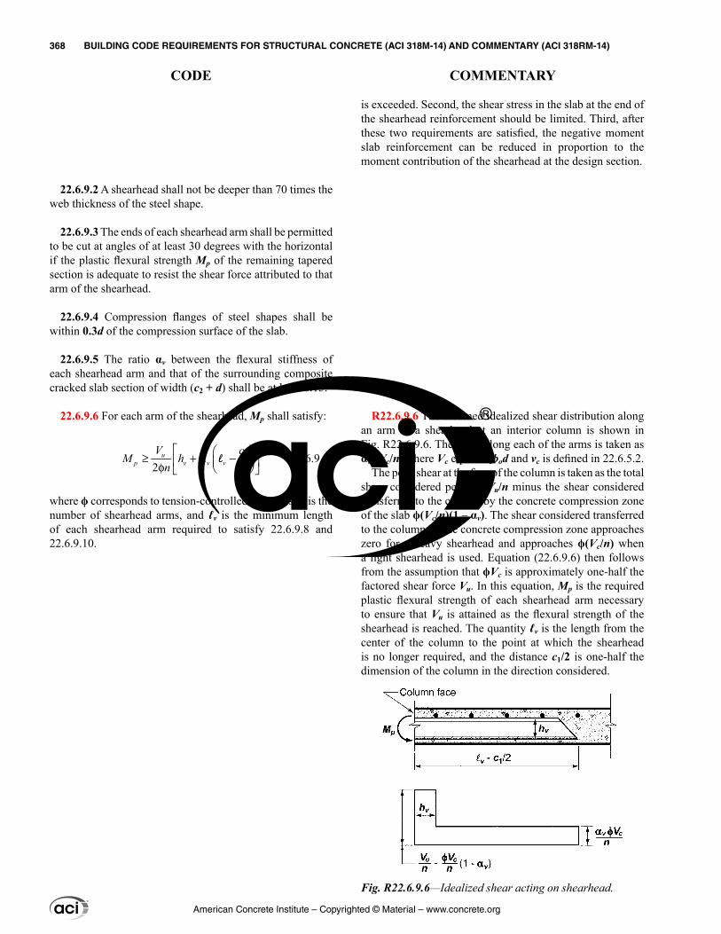
is exceeded. Second, the shear stress in the slab at the end of the shearhead reinforcement should be limited. Third, after these two requirements are satisfied, the negative moment slab reinforcement can be reduced in proportion to the moment contribution of the shearhead at the design section.
R22.6.9.6 The assumed idealized shear distribution along an arm of a shearhead at an interior column is shown in Fig. R22.6.9.6. The shear along each of the arms is taken as αvϕVc/n, where Vc equals vcbod and vc is defined in 22.6.5.2.
The peak shear at the face of the column is taken as the total shear considered per arm Vu/n minus the shear considered transferred to the column by the concrete compression zone of the slab ϕ(Vc/n)(1 – αv). The shear considered transferred to the column by the concrete compression zone approaches zero for a heavy shearhead and approaches ϕ(Vc/n) when a light shearhead is used. Equation (22.6.9.6) then follows from the assumption that ϕVc is approximately one-half the factored shear force Vu. In this equation, Mp is the required plastic flexural strength of each shearhead arm necessary to ensure that Vu is attained as the flexural strength of the shearhead is reached. The quantity ℓv is the length from the center of the column to the point at which the shearhead is no longer required, and the distance c1/2 is one-half the dimension of the column in the direction considered.
22.6.9.2 A shearhead shall not be deeper than 70 times the web thickness of the steel shape.
22.6.9.3 The ends of each shearhead arm shall be permitted to be cut at angles of at least 30 degrees with the horizontal if the plastic flexural strength Mp of the remaining tapered section is adequate to resist the shear force attributed to that arm of the shearhead.
22.6.9.4 Compression flanges of steel shapes shall be within 0.3d of the compression surface of the slab.
22.6.9.5 The ratio αv between the flexural stiffness of each shearhead arm and that of the surrounding composite cracked slab section of width (c2 + d) shall be at least 0.15.
22.6.9.6 For each arm of the shearhead, Mp shall satisfy:
1
2 2u
p v v vV c
M hn
≥ + α − φ l (22.6.9.6)
where ϕ corresponds to tension-controlled members, n is the number of shearhead arms, and ℓv is the minimum length of each shearhead arm required to satisfy 22.6.9.8 and 22.6.9.10.
Fig. R22.6.9.6—Idealized shear acting on shearhead.
American Concrete Institute – Copyrighted © Material – www.concrete.org
368 BUILDING CODE REQUIREMENTS FOR STRUCTURAL CONCRETE (ACI 318M-14) AND COMMENTARY (ACI 318RM-14)
CODE COMMENTARY
R22.6.9.7 The flexural strength contribution of the shear-head, Mv, is conservatively calculated from Eq. (22.6.9.7). This expression is based on the assumption that the peak shear at the face of the column is neglected, and ϕVc is approximately one-half the factored shear force Vu, which is consistent with the assumption used in the development of Eq. (22.6.9.6).
R22.6.9.8 Test results (Corley and Hawkins 1968) indi-cated that slabs containing shearheads for which the flexural strength of the shear arms was reached prior to slab shear failure, failed at a shear stress less than 0.33 ′fc on a critical section at the end of the shearhead reinforcement. For shear-heads where the flexural strength of the shear arms was not reached prior to slab shear failure, the shear strength was brought back to approximately the equivalent of 0.33 ′fc . The limited test data suggest that a conservative design is desirable. Therefore, the shear strength is calculated as 0.33 ′fc on an assumed critical section located inside the end of the shearhead reinforcement.
The critical section is taken through the shearhead arms three-fourths of the distance [ℓv – (c1/2)] from the face of the column to the end of the shearhead. However, this assumed critical section need not be taken closer than d/2 to the column. Refer to Fig. R22.6.9.8.
22.6.9.7 Nominal flexural strength contributed to each slab column strip by a shearhead, Mv, shall satisfy:
1
2 2v u
v vV c
Mn
φα ≤ − l (22.6.9.7)
where ϕ corresponds to tension-controlled members. However, Mv shall not exceed the least of (a) through (c):
(a) 30 percent of Mu in each slab column strip(b) Change in Mu in column strip over the length ℓv(c) Mp as given in 22.6.9.6
22.6.9.8 The critical section for shear shall be perpendic-ular to the plane of the slab and shall cross each shearhead arm at a distance (3/4)[ℓv – (c1/2)] from the column face. This critical section shall be located so that bo is a minimum, but need not be closer than d/2 to the edges of the supporting column.
American Concrete Institute – Copyrighted © Material – www.concrete.org
BUILDING CODE REQUIREMENTS FOR STRUCTURAL CONCRETE (ACI 318M-14) AND COMMENTARY (ACI 318RM-14) 369
CODE COMMENTARY
22
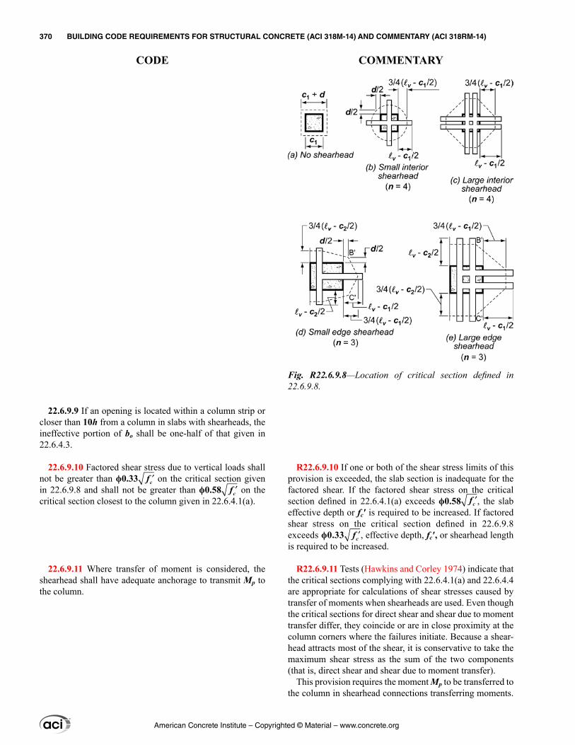
R22.6.9.10 If one or both of the shear stress limits of this provision is exceeded, the slab section is inadequate for the factored shear. If the factored shear stress on the critical section defined in 22.6.4.1(a) exceeds ϕ0.58 ′fc , the slab effective depth or fc′ is required to be increased. If factored shear stress on the critical section defined in 22.6.9.8 exceeds ϕ0.33 ′fc , effective depth, fc′, or shearhead length is required to be increased.
R22.6.9.11 Tests (Hawkins and Corley 1974) indicate that the critical sections complying with 22.6.4.1(a) and 22.6.4.4 are appropriate for calculations of shear stresses caused by transfer of moments when shearheads are used. Even though the critical sections for direct shear and shear due to moment transfer differ, they coincide or are in close proximity at the column corners where the failures initiate. Because a shear-head attracts most of the shear, it is conservative to take the maximum shear stress as the sum of the two components (that is, direct shear and shear due to moment transfer).
This provision requires the moment Mp to be transferred to the column in shearhead connections transferring moments.
22.6.9.9 If an opening is located within a column strip or closer than 10h from a column in slabs with shearheads, the ineffective portion of bo shall be one-half of that given in 22.6.4.3.
22.6.9.10 Factored shear stress due to vertical loads shall not be greater than ϕ0.33 ′fc on the critical section given in 22.6.9.8 and shall not be greater than ϕ0.58 ′fc on the critical section closest to the column given in 22.6.4.1(a).
22.6.9.11 Where transfer of moment is considered, the shearhead shall have adequate anchorage to transmit Mp to the column.
Fig. R22.6.9.8—Location of critical section defined in 22.6.9.8.
American Concrete Institute – Copyrighted © Material – www.concrete.org
370 BUILDING CODE REQUIREMENTS FOR STRUCTURAL CONCRETE (ACI 318M-14) AND COMMENTARY (ACI 318RM-14)
CODE COMMENTARY
22.6.9.12 Where transfer of moment is considered, the sum of factored shear stresses due to vertical load acting on the critical section given in 22.6.9.8 and the shear stresses resulting from factored moment transferred by eccentricity of shear about the centroid of the critical section closest to the column given in 22.6.4.1(a) shall not exceed ϕ0.33λ ′fc .
22.7—Torsional strength
This may be accomplished by bearing within the column or by mechanical anchorage.
R22.7—Torsional strength The design for torsion in this section is based on a thin-
walled tube space truss analogy. A beam subjected to torsion is idealized as a thin-walled tube with the core concrete cross section in a solid beam neglected as shown in Fig. R22.7(a). Once a reinforced concrete beam has cracked in torsion, its torsional strength is provided primarily by closed stirrups and longitudinal bars located near the surface of the member. In the thin-walled tube analogy, the strength is assumed to be provided by the outer skin of the cross section roughly centered on the closed stirrups. Both hollow and solid sections are idealized as thin-walled tubes both before and after cracking.
In a closed thin-walled tube, the product of the shear stress τ and the wall thickness t at any point in the perimeter is known as the shear flow, q = τt. The shear flow q due to torsion acts as shown in Fig. R22.7(a) and is constant at all points around the perimeter of the tube. The path along which it acts extends around the tube at midthickness of the walls of the tube. At any point along the perimeter of the tube, the shear stress due to torsion is τ = T/(2Aot), where Ao is the gross area enclosed by the shear flow path, shown shaded in Fig. R22.7(b), and t is the thickness of the wall at the point where τ is being calculated. For a hollow member with continuous walls, Ao includes the area of the hole.
The concrete contribution to torsional strength is ignored, and in cases of combined shear and torsion, the concrete contribution to shear strength does not need to be reduced. The design procedure is derived and compared with test results in MacGregor and Ghoneim (1995) and Hsu (1997).
American Concrete Institute – Copyrighted © Material – www.concrete.org
BUILDING CODE REQUIREMENTS FOR STRUCTURAL CONCRETE (ACI 318M-14) AND COMMENTARY (ACI 318RM-14) 371
CODE COMMENTARY
22
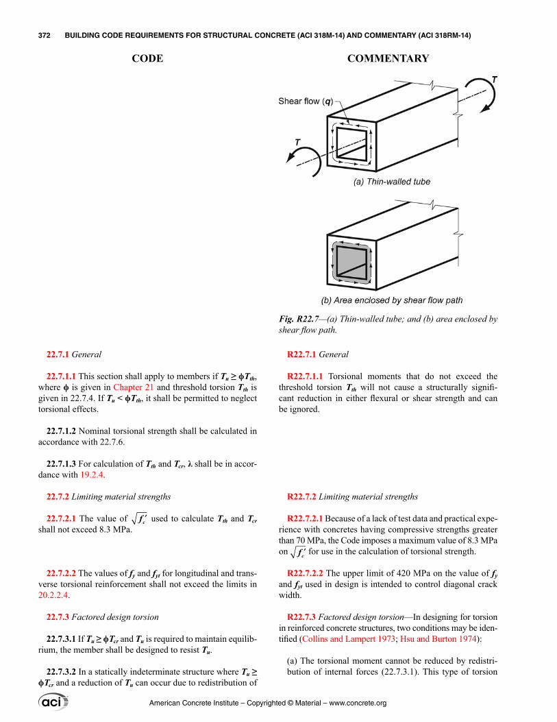
22.7.1 General
22.7.1.1 This section shall apply to members if Tu ≥ ϕTth, where ϕ is given in Chapter 21 and threshold torsion Tth is given in 22.7.4. If Tu < ϕTth, it shall be permitted to neglect torsional effects.
22.7.1.2 Nominal torsional strength shall be calculated in accordance with 22.7.6.
22.7.1.3 For calculation of Tth and Tcr, λ shall be in accor-dance with 19.2.4.
22.7.2 Limiting material strengths
22.7.2.1 The value of ′fc used to calculate Tth and Tcr shall not exceed 8.3 MPa.
22.7.2.2 The values of fy and fyt for longitudinal and trans-verse torsional reinforcement shall not exceed the limits in 20.2.2.4.
22.7.3 Factored design torsion
22.7.3.1 If Tu ≥ ϕTcr and Tu is required to maintain equilib-rium, the member shall be designed to resist Tu.
22.7.3.2 In a statically indeterminate structure where Tu ≥ ϕTcr and a reduction of Tu can occur due to redistribution of
R22.7.1 General
R22.7.1.1 Torsional moments that do not exceed the threshold torsion Tth will not cause a structurally signifi-cant reduction in either flexural or shear strength and can be ignored.
R22.7.2 Limiting material strengths
R22.7.2.1 Because of a lack of test data and practical expe-rience with concretes having compressive strengths greater than 70 MPa, the Code imposes a maximum value of 8.3 MPa on ′fc for use in the calculation of torsional strength.
R22.7.2.2 The upper limit of 420 MPa on the value of fy and fyt used in design is intended to control diagonal crack width.
R22.7.3 Factored design torsion—In designing for torsion in reinforced concrete structures, two conditions may be iden-tified (Collins and Lampert 1973; Hsu and Burton 1974):
(a) The torsional moment cannot be reduced by redistri-bution of internal forces (22.7.3.1). This type of torsion
Fig. R22.7—(a) Thin-walled tube; and (b) area enclosed by shear flow path.
American Concrete Institute – Copyrighted © Material – www.concrete.org
372 BUILDING CODE REQUIREMENTS FOR STRUCTURAL CONCRETE (ACI 318M-14) AND COMMENTARY (ACI 318RM-14)
CODE COMMENTARY
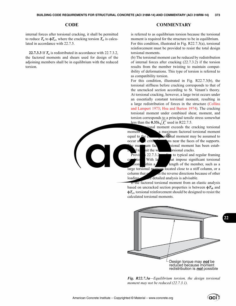
internal forces after torsional cracking, it shall be permitted to reduce Tu to ϕTcr, where the cracking torsion Tcr is calcu-lated in accordance with 22.7.5.
22.7.3.3 If Tu is redistributed in accordance with 22.7.3.2, the factored moments and shears used for design of the adjoining members shall be in equilibrium with the reduced torsion.
is referred to as equilibrium torsion because the torsional moment is required for the structure to be in equilibrium.For this condition, illustrated in Fig. R22.7.3(a), torsional reinforcement must be provided to resist the total design torsional moments.(b) The torsional moment can be reduced by redistribution of internal forces after cracking (22.7.3.2) if the torsion results from the member twisting to maintain compat-ibility of deformations. This type of torsion is referred to as compatibility torsion.For this condition, illustrated in Fig. R22.7.3(b), the torsional stiffness before cracking corresponds to that of the uncracked section according to St. Venant’s theory. At torsional cracking, however, a large twist occurs under an essentially constant torsional moment, resulting in a large redistribution of forces in the structure (Collins and Lampert 1973; Hsu and Burton 1974). The cracking torsional moment under combined shear, moment, and torsion corresponds to a principal tensile stress somewhat less than the 0.33λ ′fc used in R22.7.5.If the torsional moment exceeds the cracking torsional
moment (22.7.3.2), a maximum factored torsional moment equal to the cracking torsional moment may be assumed to occur at the critical sections near the faces of the supports. The maximum factored torsional moment has been estab-lished to limit the width of torsional cracks.
Provision 22.7.3.2 applies to typical and regular framing conditions. With layouts that impose significant torsional rotations within a limited length of the member, such as a large torsional moment located close to a stiff column, or a column that rotates in the reverse directions because of other loading, a more detailed analysis is advisable.
If the factored torsional moment from an elastic analysis based on uncracked section properties is between ϕTth and ϕTcr, torsional reinforcement should be designed to resist the calculated torsional moments.
Fig. R22.7.3a—Equilibrium torsion, the design torsional moment may not be reduced (22.7.3.1).
American Concrete Institute – Copyrighted © Material – www.concrete.org
BUILDING CODE REQUIREMENTS FOR STRUCTURAL CONCRETE (ACI 318M-14) AND COMMENTARY (ACI 318RM-14) 373
CODE COMMENTARY
22
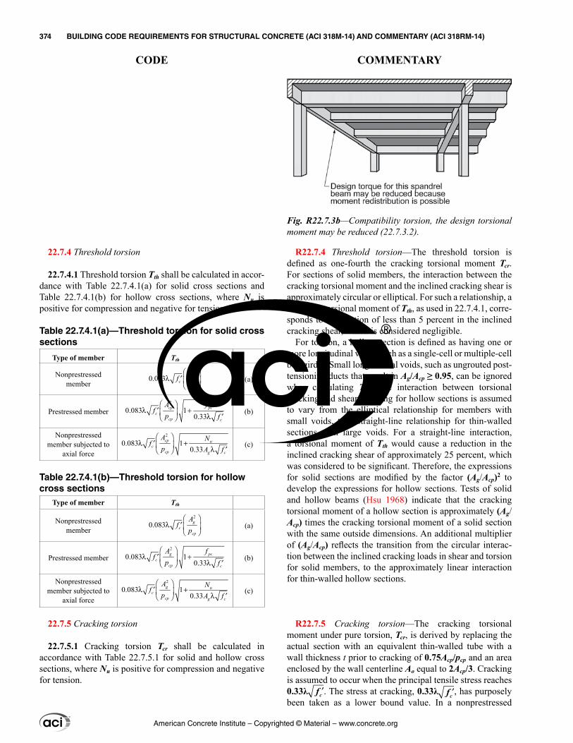
22.7.4 Threshold torsion
22.7.4.1 Threshold torsion Tth shall be calculated in accor-dance with Table 22.7.4.1(a) for solid cross sections and Table 22.7.4.1(b) for hollow cross sections, where Nu is positive for compression and negative for tension.
Table 22.7.4.1(a)—Threshold torsion for solid cross sections
Type of member Tth
Nonprestressed member
2
0.083
λ ′
cpc
cp
Af
p (a)
Prestressed member2
0.083 10.33
λ +′ λ ′
cp pcc
cp c
A ff
p f(b)
Nonprestressed member subjected to
axial force
2
0.083 10.33
λ +′ λ ′
cp uc
cp g c
A Nfp A f
(c)
Table 22.7.4.1(b)—Threshold torsion for hollow cross sections
Type of member Tth
Nonprestressed member
2
0.083
λ ′
gc
cp
Af
p (a)
Prestressed member2
0.083 10.33
λ +′ λ ′
g pcc
cp c
A ff
p f(b)
Nonprestressed member subjected to
axial force
2
0.083 10.33
λ +′ λ ′
g uc
cp g c
A Nfp A f
(c)
22.7.5 Cracking torsion
22.7.5.1 Cracking torsion Tcr shall be calculated in accordance with Table 22.7.5.1 for solid and hollow cross sections, where Nu is positive for compression and negative for tension.
R22.7.4 Threshold torsion—The threshold torsion is defined as one-fourth the cracking torsional moment Tcr. For sections of solid members, the interaction between the cracking torsional moment and the inclined cracking shear is approximately circular or elliptical. For such a relationship, a threshold torsional moment of Tth, as used in 22.7.4.1, corre-sponds to a reduction of less than 5 percent in the inclined cracking shear, which is considered negligible.
For torsion, a hollow section is defined as having one or more longitudinal voids, such as a single-cell or multiple-cell box girder. Small longitudinal voids, such as ungrouted post-tensioning ducts that result in Ag/Acp ≥ 0.95, can be ignored when calculating Tth. The interaction between torsional cracking and shear cracking for hollow sections is assumed to vary from the elliptical relationship for members with small voids, to a straight-line relationship for thin-walled sections with large voids. For a straight-line interaction, a torsional moment of Tth would cause a reduction in the inclined cracking shear of approximately 25 percent, which was considered to be significant. Therefore, the expressions for solid sections are modified by the factor (Ag/Acp)2 to develop the expressions for hollow sections. Tests of solid and hollow beams (Hsu 1968) indicate that the cracking torsional moment of a hollow section is approximately (Ag/Acp) times the cracking torsional moment of a solid section with the same outside dimensions. An additional multiplier of (Ag/Acp) reflects the transition from the circular interac-tion between the inclined cracking loads in shear and torsion for solid members, to the approximately linear interaction for thin-walled hollow sections.
R22.7.5 Cracking torsion—The cracking torsional moment under pure torsion, Tcr, is derived by replacing the actual section with an equivalent thin-walled tube with a wall thickness t prior to cracking of 0.75Acp/pcp and an area enclosed by the wall centerline Ao equal to 2Acp/3. Cracking is assumed to occur when the principal tensile stress reaches 0.33λ ′fc . The stress at cracking, 0.33λ ′fc , has purposely been taken as a lower bound value. In a nonprestressed
Fig. R22.7.3b—Compatibility torsion, the design torsional moment may be reduced (22.7.3.2).
American Concrete Institute – Copyrighted © Material – www.concrete.org
374 BUILDING CODE REQUIREMENTS FOR STRUCTURAL CONCRETE (ACI 318M-14) AND COMMENTARY (ACI 318RM-14)
CODE COMMENTARY
Table 22.7.5.1—Cracking torsionType of member Tcr
Nonprestressed member2
0.33
λ ′
cpc
cp
Af
p (a)
Prestressed member2
0.33 10.33
λ +′ λ ′
cp pcc
cp c
A ff
p f(b)
Nonprestressed member subjected to axial force
2
0.33 10.33
λ +′ λ ′
cp uc
cp g c
A Nfp A f
(c)
22.7.6 Torsional strength
22.7.6.1 For nonprestressed and prestressed members, Tn shall be the lesser of (a) and (b):
(a) 2
coto t ytn
A A fT
s= θ (22.7.6.1a)
(b) 2
coto yn
h
A A fT
p= θl (22.7.6.1b)
where Ao shall be determined by analysis, θ shall not be taken less than 30 degrees nor greater than 60 degrees; At is the area of one leg of a closed stirrup resisting torsion; Aℓ is the area of longitudinal torsional reinforcement; and ph is the perimeter of the centerline of the outermost closed stirrup.
beam loaded with torsion alone, the principal tensile stress is equated to the torsional shear stress, τ = T/(2Aot). Thus, cracking occurs when τ reaches 0.33λ ′fc , giving the cracking torsional moment Tcr as defined by expression (a) in Table 22.7.5.1.
For prestressed members, the torsional cracking load is increased by the prestress given by expression (b) in Table 22.7.5.1. A Mohr’s Circle analysis based on average stresses indicates the torsional moment required to cause a principal tensile stress equal to 0.33λ ′fc is /( )+ ′1 0.33pc cf fλ times the corresponding torsional cracking moment in a nonpre-stressed beam. A similar modification is made in expression (c) in Table 22.7.5.1 for members subjected to axial force and torsion.
If the factored torsional moment exceeds ϕTcr in a stati-cally indeterminate structure, a maximum factored torsional moment equal to ϕTcr may be assumed to occur at critical sections near the faces of the supports. This limit has been established to control the width of the torsional cracks. The replacement of Acp with Ag, as in the calculation of Tth for hollow sections in 22.7.4.1, is not applied here. Thus, the torsional moment after redistribution is larger and, hence, more conservative.
R22.7.6 Torsional strength—The torsional design strength ϕTn must equal or exceed the torsional moment Tu due to factored loads. In the calculation of Tn, all the torsion is assumed to be resisted by stirrups and longitudinal rein-forcement, neglecting any concrete contribution to torsional strength. At the same time, the nominal shear strength provided by concrete, Vc, is assumed to be unchanged by the presence of torsion.
R22.7.6.1 Equation (22.7.6.1a) is based on the space truss analogy shown in Fig. R22.7.6.1a with compression diago-nals at an angle θ, assuming the concrete resists no tension and the reinforcement yields. After torsional cracking develops, the torsional strength is provided mainly by closed stirrups, longitudinal reinforcement, and compression diago-nals. The concrete outside these stirrups is relatively ineffec-tive. For this reason Ao, the gross area enclosed by the shear flow path around the perimeter of the tube, is defined after cracking in terms of Aoh, the area enclosed by the centerline of the outermost closed transverse torsional reinforcement.
The shear flow q in the walls of the tube, discussed in R22.7, can be resolved into the shear forces V1 to V4 acting in the individual sides of the tube or space truss, as shown in Fig. R22.7.6.1a.
As shown in Figure R22.7.6.1b, on a given wall of the tube, the shear flow Vi is resisted by a diagonal compression component, Di = Vi/sinθ, in the concrete. An axial tension force, Ni = Vi(cotθ), is required in the longitudinal reinforce-ment to complete the resolution of Vi.
Because the shear flow due to torsion is constant at all points around the perimeter of the tube, the resultants of Di and Ni act through the midheight of side i. As a result, half
American Concrete Institute – Copyrighted © Material – www.concrete.org
BUILDING CODE REQUIREMENTS FOR STRUCTURAL CONCRETE (ACI 318M-14) AND COMMENTARY (ACI 318RM-14) 375
CODE COMMENTARY
22
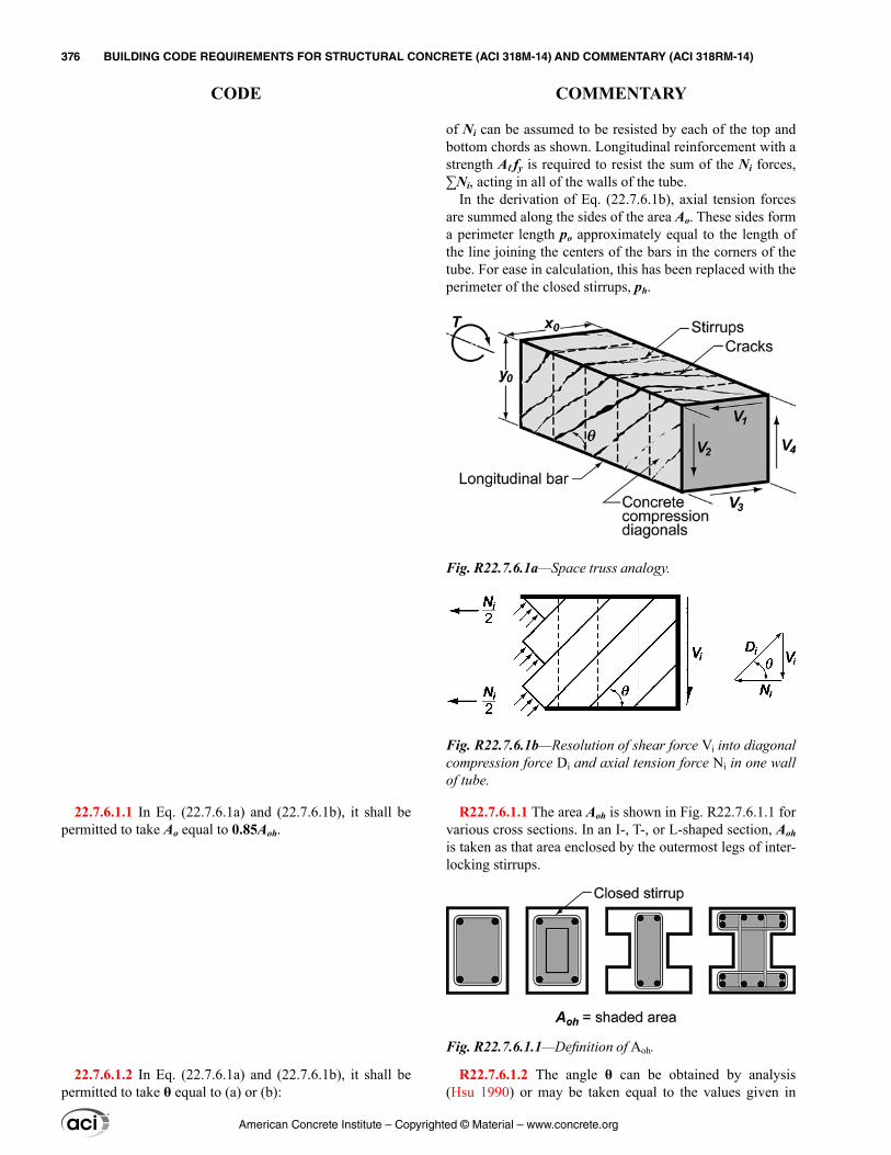
22.7.6.1.1 In Eq. (22.7.6.1a) and (22.7.6.1b), it shall be permitted to take Ao equal to 0.85Aoh.
22.7.6.1.2 In Eq. (22.7.6.1a) and (22.7.6.1b), it shall be permitted to take θ equal to (a) or (b):
of Ni can be assumed to be resisted by each of the top and bottom chords as shown. Longitudinal reinforcement with a strength Aℓ fy is required to resist the sum of the Ni forces, ∑Ni, acting in all of the walls of the tube.
In the derivation of Eq. (22.7.6.1b), axial tension forces are summed along the sides of the area Ao. These sides form a perimeter length po approximately equal to the length of the line joining the centers of the bars in the corners of the tube. For ease in calculation, this has been replaced with the perimeter of the closed stirrups, ph.
R22.7.6.1.1 The area Aoh is shown in Fig. R22.7.6.1.1 for various cross sections. In an I-, T-, or L-shaped section, Aoh is taken as that area enclosed by the outermost legs of inter-locking stirrups.
R22.7.6.1.2 The angle θ can be obtained by analysis (Hsu 1990) or may be taken equal to the values given in
Fig. R22.7.6.1a—Space truss analogy.
Fig. R22.7.6.1b—Resolution of shear force Vi into diagonal compression force Di and axial tension force Ni in one wall of tube.
Fig. R22.7.6.1.1—Definition of Aoh.
American Concrete Institute – Copyrighted © Material – www.concrete.org
376 BUILDING CODE REQUIREMENTS FOR STRUCTURAL CONCRETE (ACI 318M-14) AND COMMENTARY (ACI 318RM-14)
CODE COMMENTARY
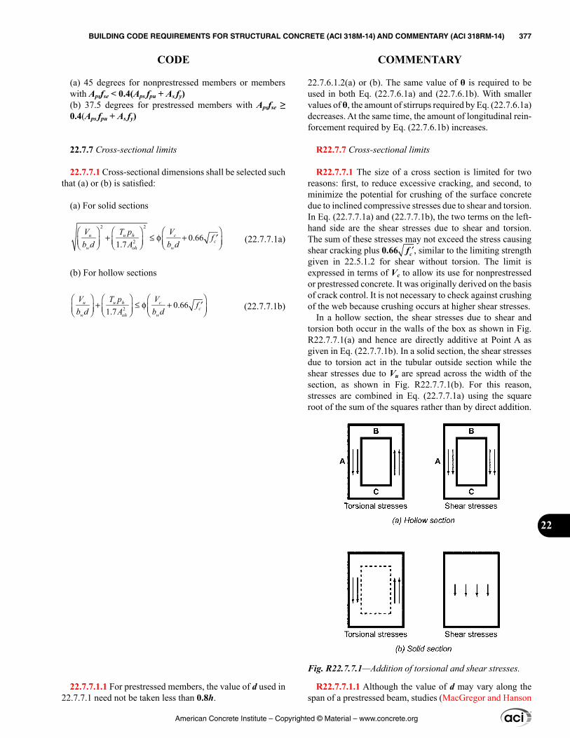
(a) 45 degrees for nonprestressed members or members with Apsfse < 0.4(Aps fpu + As fy)(b) 37.5 degrees for prestressed members with Apsfse ≥ 0.4(Aps fpu + As fy)
22.7.7 Cross-sectional limits
22.7.7.1 Cross-sectional dimensions shall be selected such that (a) or (b) is satisfied:
(a) For solid sections
22
2 0.661.7
+ ≤ φ + ′
u u h cc
w woh
V T p Vf
b d b dA (22.7.7.1a)
(b) For hollow sections
2 0.661.7
+ ≤ φ + ′
u u h cc
w woh
V T p Vf
b d b dA (22.7.7.1b)
22.7.7.1.1 For prestressed members, the value of d used in 22.7.7.1 need not be taken less than 0.8h.
22.7.6.1.2(a) or (b). The same value of θ is required to be used in both Eq. (22.7.6.1a) and (22.7.6.1b). With smaller values of θ, the amount of stirrups required by Eq. (22.7.6.1a) decreases. At the same time, the amount of longitudinal rein-forcement required by Eq. (22.7.6.1b) increases.
R22.7.7 Cross-sectional limits
R22.7.7.1 The size of a cross section is limited for two reasons: first, to reduce excessive cracking, and second, to minimize the potential for crushing of the surface concrete due to inclined compressive stresses due to shear and torsion. In Eq. (22.7.7.1a) and (22.7.7.1b), the two terms on the left-hand side are the shear stresses due to shear and torsion. The sum of these stresses may not exceed the stress causing shear cracking plus 0.66 ′fc , similar to the limiting strength given in 22.5.1.2 for shear without torsion. The limit is expressed in terms of Vc to allow its use for nonprestressed or prestressed concrete. It was originally derived on the basis of crack control. It is not necessary to check against crushing of the web because crushing occurs at higher shear stresses.
In a hollow section, the shear stresses due to shear and torsion both occur in the walls of the box as shown in Fig. R22.7.7.1(a) and hence are directly additive at Point A as given in Eq. (22.7.7.1b). In a solid section, the shear stresses due to torsion act in the tubular outside section while the shear stresses due to Vu are spread across the width of the section, as shown in Fig. R22.7.7.1(b). For this reason, stresses are combined in Eq. (22.7.7.1a) using the square root of the sum of the squares rather than by direct addition.
R22.7.7.1.1 Although the value of d may vary along the span of a prestressed beam, studies (MacGregor and Hanson
Fig. R22.7.7.1—Addition of torsional and shear stresses.
American Concrete Institute – Copyrighted © Material – www.concrete.org
BUILDING CODE REQUIREMENTS FOR STRUCTURAL CONCRETE (ACI 318M-14) AND COMMENTARY (ACI 318RM-14) 377
CODE COMMENTARY
22
1969) have shown that, for prestressed concrete members, d need not be taken less than 0.8h. The beams considered had some straight prestressed reinforcement or reinforcing bars at the bottom of the section and had stirrups that enclosed the longitudinal reinforcement.
R22.7.7.1.2 Generally, the maximum torsional stress will be on the wall where the torsional and shearing stresses are additive (Point A in Fig. R22.7.7.1(a)). If the top or bottom flanges are thinner than the vertical webs, it may be neces-sary to evaluate Eq. (22.7.7.1b) at Points B and C in Fig. R22.7.7.1(a). At these points, the stresses due to the shear are usually negligible.
R22.8—Bearing R22.8.1 General
R22.8.1.2 Because post-tensioned anchorage zones are usually designed in accordance with 25.9, the bearing strength provisions in 22.8 are not applicable.
R22.8.3 Design strength
R22.8.3.2 The permissible bearing stress of 0.85fc′ is based on tests reported in Hawkins (1968). Where the supporting area is wider than the loaded area on all sides, the surrounding concrete confines the bearing area, resulting in an increase in bearing strength. No minimum depth is given for the support, which will most likely be controlled by the punching shear requirements of 22.6.
A1 is the loaded area but not greater than the bearing plate or bearing cross-sectional area.
22.7.7.1.2 For hollow sections where the wall thickness varies around the perimeter, Eq. (22.7.7.1b) shall be evalu-ated at the location where the term
21.7u u h
w oh
V T pb d A
+
is a maximum.
22.7.7.2 For hollow sections where the wall thickness is less than Aoh/ph, the term (Tuph/1.7Aoh
2) in Eq. (22.7.7.1b) shall be taken as (Tu/1.7Aoht), where t is the thickness of the wall of the hollow section at the location where the stresses are being checked.
22.8—Bearing 22.8.1 General
22.8.1.1 Section 22.8 shall apply to the calculation of bearing strength of concrete members.
22.8.1.2 Bearing strength provisions in 22.8 shall not apply to post-tensioned anchorage zones or strut-and-tie models.
22.8.2 Required strength
22.8.2.1 Factored compressive force transferred through bearing shall be calculated in accordance with the factored load combinations defined in Chapter 5 and analysis proce-dures defined in Chapter 6.
22.8.3 Design strength
22.8.3.1 Design bearing strength shall satisfy:
ϕBn ≥ Bu (22.8.3.1)
for each applicable factored load combination.
22.8.3.2 Nominal bearing strength Bn shall be calculated in accordance with Table 22.8.3.2, where A1 is the loaded area, and A2 is the area of the lower base of the largest frustum of a pyramid, cone, or tapered wedge contained wholly within the support and having its upper base equal to the loaded area. The sides of the pyramid, cone, or tapered wedge shall be sloped 1 vertical to 2 horizontal.
American Concrete Institute – Copyrighted © Material – www.concrete.org
378 BUILDING CODE REQUIREMENTS FOR STRUCTURAL CONCRETE (ACI 318M-14) AND COMMENTARY (ACI 318RM-14)
CODE COMMENTARY
Where the top of the support is sloped or stepped, advan-tage may still be taken of the condition that the supporting member is larger than the loaded area, provided the supporting member does not slope at too great an angle. Figure R22.8.3.2 illustrates the application of the frustum to find A2 for a support under vertical load transfer.
Adequate bearing strength needs to be provided for cases where the compression force transfer is in a direction other than normal to the bearing surface. For such cases, this section applies to the normal component and the tangential component needs to be transferred by other methods, such as by anchor bolts or shear lugs.
The frustum should not be confused with the path by which a load spreads out as it progresses downward through the support. Such a load path would have steeper sides. However, the frustum described has somewhat flat side slopes to ensure that there is concrete immediately surrounding the zone of high stress at the bearing.
Where tensile forces occur in the plane of bearing, it may be desirable to reduce the allowable bearing stress, provide confinement reinforcement, or both. Guidelines are provided in the PCI Design Handbook for precast and prestressed concrete (PCI MNL 120).
Table 22.8.3.2—Nominal bearing strength
Geometry of bearing area Bn
Supporting surface is wider on all sides than the loaded
area
Lesser of (a) and (b)
2 1/ (0.85 )c gA A f A′ (a)
2(0.85fc′A1) (b)
Other cases 0.85fc′A1 (c)
American Concrete Institute – Copyrighted © Material – www.concrete.org
BUILDING CODE REQUIREMENTS FOR STRUCTURAL CONCRETE (ACI 318M-14) AND COMMENTARY (ACI 318RM-14) 379
CODE COMMENTARY
22
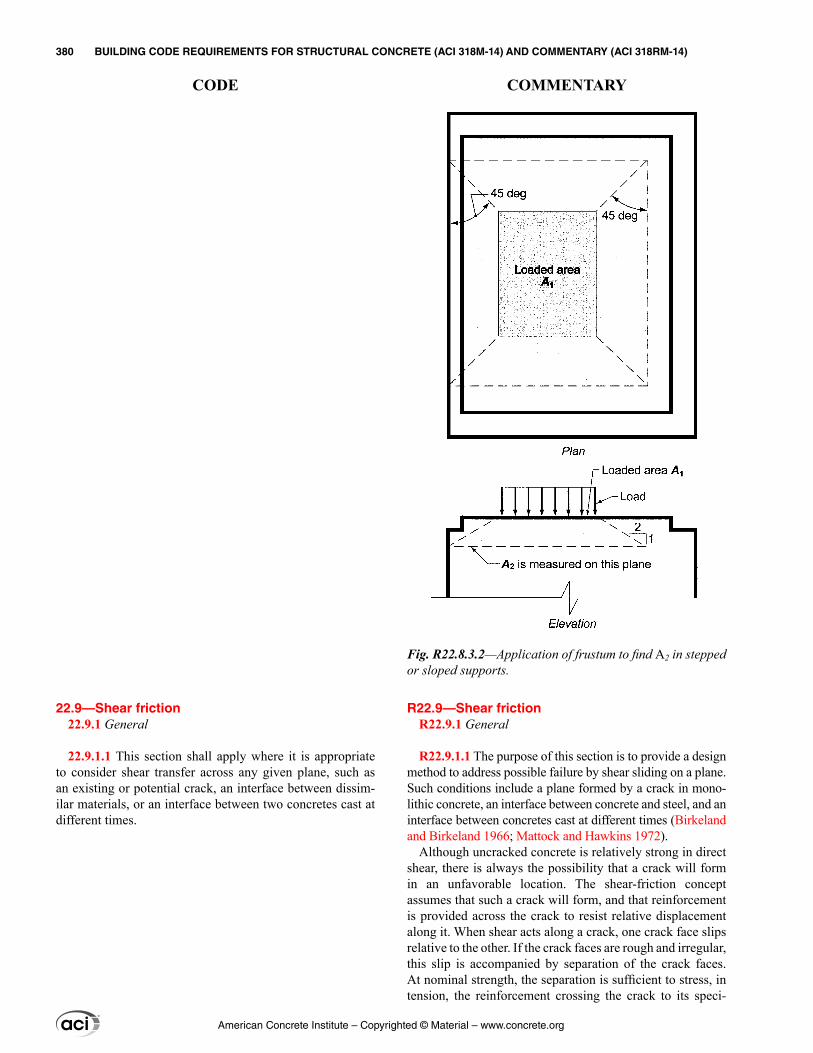
R22.9—Shear friction R22.9.1 General
R22.9.1.1 The purpose of this section is to provide a design method to address possible failure by shear sliding on a plane. Such conditions include a plane formed by a crack in mono-lithic concrete, an interface between concrete and steel, and an interface between concretes cast at different times (Birkeland and Birkeland 1966; Mattock and Hawkins 1972).
Although uncracked concrete is relatively strong in direct shear, there is always the possibility that a crack will form in an unfavorable location. The shear-friction concept assumes that such a crack will form, and that reinforcement is provided across the crack to resist relative displacement along it. When shear acts along a crack, one crack face slips relative to the other. If the crack faces are rough and irregular, this slip is accompanied by separation of the crack faces. At nominal strength, the separation is sufficient to stress, in tension, the reinforcement crossing the crack to its speci-
22.9—Shear friction 22.9.1 General
22.9.1.1 This section shall apply where it is appropriate to consider shear transfer across any given plane, such as an existing or potential crack, an interface between dissim-ilar materials, or an interface between two concretes cast at different times.
Fig. R22.8.3.2—Application of frustum to find A2 in stepped or sloped supports.
American Concrete Institute – Copyrighted © Material – www.concrete.org
380 BUILDING CODE REQUIREMENTS FOR STRUCTURAL CONCRETE (ACI 318M-14) AND COMMENTARY (ACI 318RM-14)
CODE COMMENTARY
fied yield strength. The reinforcement in tension provides a clamping force Avf fy across the crack faces. The applied shear is then resisted by friction between the crack faces, by resistance to the shearing off of protrusions on the crack faces, and by dowel action of the reinforcement crossing the crack. Successful application of this section depends on proper selection of the location of an assumed crack (PCI MNL 120; Birkeland and Birkeland 1966).
R22.9.1.2 The relationship between shear-transfer strength and the reinforcement crossing the shear plane can be expressed in various ways. Equations (22.9.4.2) and (22.9.4.3) are based on the shear-friction model and provide a conservative estimate of the shear-transfer strength.
Other relationships that provide a more accurate estimate of shear-transfer strength can be used under the requirements of this section. Examples of such procedures can be found in the PCI Design Handbook (PCI MNL 120), Mattock et al. (1976b), and Mattock (1974).
R22.9.1.4 For concrete cast against hardened concrete or structural steel, 26.5.6.1 requires the licensed design profes-sional to specify the surface preparation in the construction documents.
R22.9.4 Nominal shear strength
R22.9.4.2 The required area of shear-friction reinforce-ment, Avf, is calculated using:
uvf
y
VA
f=
φ µ (R22.9.4.2)
22.9.1.2 The required area of shear-friction reinforcement across the assumed shear plane, Avf, shall be calculated in accordance with 22.9.4. Alternatively, it shall be permitted to use shear transfer design methods that result in prediction of strength in substantial agreement with results of compre-hensive tests.
22.9.1.3 The value of fy used to calculate Vn for shear fric-tion shall not exceed the limit in 20.2.2.4.
22.9.1.4 Surface preparation of the shear plane assumed for design shall be specified in the construction documents.
22.9.2 Required strength
22.9.2.1 Factored forces across the assumed shear plane shall be calculated in accordance with the factored load combinations defined in Chapter 5 and analysis procedures defined in Chapter 6.
22.9.3 Design strength
22.9.3.1 Design shear strength across the assumed shear plane shall satisfy:
ϕVn ≥ Vu (22.9.3.1)
for each applicable factored load combination.
22.9.4 Nominal shear strength
22.9.4.1 Value of Vn across the assumed shear plane shall be calculated in accordance with 22.9.4.2 or 22.9.4.3. Vn shall not exceed the value calculated in accordance with 22.9.4.4.
22.9.4.2 If shear-friction reinforcement is perpendicular to the shear plane, nominal shear strength across the assumed shear plane shall be calculated by:
Vn = μAvf fy (22.9.4.2)
American Concrete Institute – Copyrighted © Material – www.concrete.org
BUILDING CODE REQUIREMENTS FOR STRUCTURAL CONCRETE (ACI 318M-14) AND COMMENTARY (ACI 318RM-14) 381
CODE COMMENTARY
22
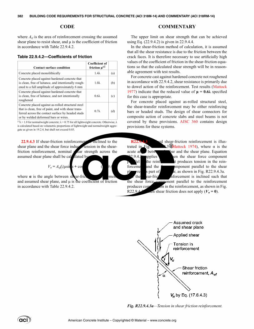
The upper limit on shear strength that can be achieved using Eq. (22.9.4.2) is given in 22.9.4.4.
In the shear-friction method of calculation, it is assumed that all the shear resistance is due to the friction between the crack faces. It is therefore necessary to use artificially high values of the coefficient of friction in the shear-friction equa-tions so that the calculated shear strength will be in reason-able agreement with test results.
For concrete cast against hardened concrete not roughened in accordance with 22.9.4.2, shear resistance is primarily due to dowel action of the reinforcement. Test results (Mattock 1977) indicate that the reduced value of μ = 0.6λ specified for this case is appropriate.
For concrete placed against as-rolled structural steel, the shear-transfer reinforcement may be either reinforcing bars or headed studs. The design of shear connectors for composite action of concrete slabs and steel beams is not covered by these provisions. AISC 360 contains design provisions for these systems.
R22.9.4.3 Inclined shear-friction reinforcement is illus-trated in Fig. R22.9.4.3 (Mattock 1974), where α is the acute angle between the bar and the shear plane. Equation (22.9.4.3) applies only when the shear force component parallel to the reinforcement produces tension in the rein-forcement and the force component parallel to the shear plane resists part of the shear, as shown in Fig. R22.9.4.3a.
If the shear-friction reinforcement is inclined such that the shear force component parallel to the reinforcement produces compression in the reinforcement, as shown in Fig. R22.9.4.3b, then shear friction does not apply (Vn = 0).
where Avf is the area of reinforcement crossing the assumed shear plane to resist shear, and μ is the coefficient of friction in accordance with Table 22.9.4.2.
Table 22.9.4.2—Coefficients of friction
Contact surface conditionCoefficient of friction μ[1]
Concrete placed monolithically 1.4λ (a)
Concrete placed against hardened concrete that is clean, free of laitance, and intentionally rough-ened to a full amplitude of approximately 6 mm
1.0λ (b)
Concrete placed against hardened concrete that is clean, free of laitance, and not intentionally roughened
0.6λ (c)
Concrete placed against as-rolled structural steel that is clean, free of paint, and with shear trans-ferred across the contact surface by headed studs or by welded deformed bars or wires.
0.7λ (d)
[1]λ = 1.0 for normalweight concrete; λ = 0.75 for all lightweight concrete. Otherwise, λ is calculated based on volumetric proportions of lightweight and normalweight aggre-gate as given in 19.2.4, but shall not exceed 0.85.
22.9.4.3 If shear-friction reinforcement is inclined to the shear plane and the shear force induces tension in the shear-friction reinforcement, nominal shear strength across the assumed shear plane shall be calculated by:
Vn = Avffy(μsinα + cosα) (22.9.4.3)
where α is the angle between shear-friction reinforcement and assumed shear plane, and μ is the coefficient of friction in accordance with Table 22.9.4.2.
Fig. R22.9.4.3a—Tension in shear friction reinforcement.
American Concrete Institute – Copyrighted © Material – www.concrete.org
382 BUILDING CODE REQUIREMENTS FOR STRUCTURAL CONCRETE (ACI 318M-14) AND COMMENTARY (ACI 318RM-14)
CODE COMMENTARY
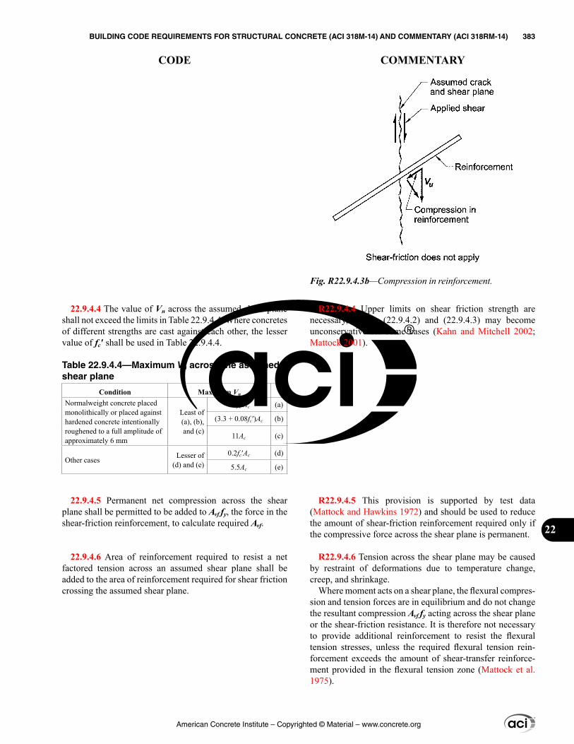
R22.9.4.4 Upper limits on shear friction strength are necessary, as Eq. (22.9.4.2) and (22.9.4.3) may become unconservative for some cases (Kahn and Mitchell 2002; Mattock 2001).
R22.9.4.5 This provision is supported by test data (Mattock and Hawkins 1972) and should be used to reduce the amount of shear-friction reinforcement required only if the compressive force across the shear plane is permanent.
R22.9.4.6 Tension across the shear plane may be caused by restraint of deformations due to temperature change, creep, and shrinkage.
Where moment acts on a shear plane, the flexural compres-sion and tension forces are in equilibrium and do not change the resultant compression Avf fy acting across the shear plane or the shear-friction resistance. It is therefore not necessary to provide additional reinforcement to resist the flexural tension stresses, unless the required flexural tension rein-forcement exceeds the amount of shear-transfer reinforce-ment provided in the flexural tension zone (Mattock et al. 1975).
22.9.4.4 The value of Vn across the assumed shear plane shall not exceed the limits in Table 22.9.4.4. Where concretes of different strengths are cast against each other, the lesser value of fc′ shall be used in Table 22.9.4.4.
Table 22.9.4.4—Maximum Vn across the assumed shear plane
Condition Maximum Vn
Normalweight concrete placed monolithically or placed against hardened concrete intentionally roughened to a full amplitude of approximately 6 mm
Least of (a), (b), and (c)
0.2fc′Ac (a)
(3.3 + 0.08fc′)Ac (b)
11Ac (c)
Other cases Lesser of (d) and (e)
0.2fc′Ac (d)
5.5Ac (e)
22.9.4.5 Permanent net compression across the shear plane shall be permitted to be added to Avf fy, the force in the shear-friction reinforcement, to calculate required Avf.
22.9.4.6 Area of reinforcement required to resist a net factored tension across an assumed shear plane shall be added to the area of reinforcement required for shear friction crossing the assumed shear plane.
Fig. R22.9.4.3b—Compression in reinforcement.
American Concrete Institute – Copyrighted © Material – www.concrete.org
BUILDING CODE REQUIREMENTS FOR STRUCTURAL CONCRETE (ACI 318M-14) AND COMMENTARY (ACI 318RM-14) 383
CODE COMMENTARY
22
R22.9.5 Detailing for shear-friction reinforcement
R22.9.5.1 If no moment acts across the shear plane, rein-forcement should be uniformly distributed along the shear plane to minimize crack widths. If a moment acts across the shear plane, the shear-transfer reinforcement should be placed primarily in the flexural tension zone.
Anchorage may be developed by bond, by a mechanical device, or by threaded dowels and screw inserts. Space limitations often require the use of mechanical anchorage devices. For anchorage of headed studs in concrete, refer to PCI Design Handbook for precast and prestressed concrete (PCI MNL 120).
The shear-friction reinforcement anchorage should engage the primary reinforcement; otherwise, a potential crack may pass between the shear-friction reinforcement and the body of the concrete. This requirement applies particularly to welded headed studs used with steel inserts.
22.9.5 Detailing for shear-friction reinforcement
22.9.5.1 Reinforcement crossing the shear plane to satisfy 22.9.4 shall be anchored to develop fy on both sides of the shear plane.
American Concrete Institute – Copyrighted © Material – www.concrete.org
384 BUILDING CODE REQUIREMENTS FOR STRUCTURAL CONCRETE (ACI 318M-14) AND COMMENTARY (ACI 318RM-14)
CODE COMMENTARY
CHAPTER 23—STRUT-AND-TIE MODELS
23.1—Scope 23.1.1 This chapter shall apply to the design of structural
concrete members, or regions of members, where load or geometric discontinuities cause a nonlinear distribution of longitudinal strains within the cross section.
23.1.2 Any structural concrete member, or discontinuity region in a member, shall be permitted to be designed by modeling the member or region as an idealized truss in accordance with this chapter.
R23—STRUT-AND-TIE MODELS
R23.1—Scope A discontinuity in the stress distribution occurs at a change
in the geometry of a structural element or at a concentrated load or reaction. St. Venant’s principle indicates that the stresses due to axial force and bending approach a linear distribution at a distance approximately equal to the overall depth of the member, h, away from the discontinuity. For this reason, discontinuity regions are assumed to extend a distance h from the section where the load or change in geometry occurs.
The shaded regions in Fig. R23.1(a) and (b) show typical D-regions (Schlaich et al. 1987). The plane sections assump-tion of 9.2.1 is not applicable in such regions. In general, any portion of a member outside a D-region is a B-region where the plane sections assumptions of flexural theory can be applied. The strut-and-tie design method, as described in this chapter, is based on the assumption that D-regions can be analyzed and designed using hypothetical pin-jointed trusses consisting of struts and ties connected at nodes.
American Concrete Institute – Copyrighted © Material – www.concrete.org
CHAPTER 23—STRUT-AND-TIE MODELS 385
CODE COMMENTARY
23
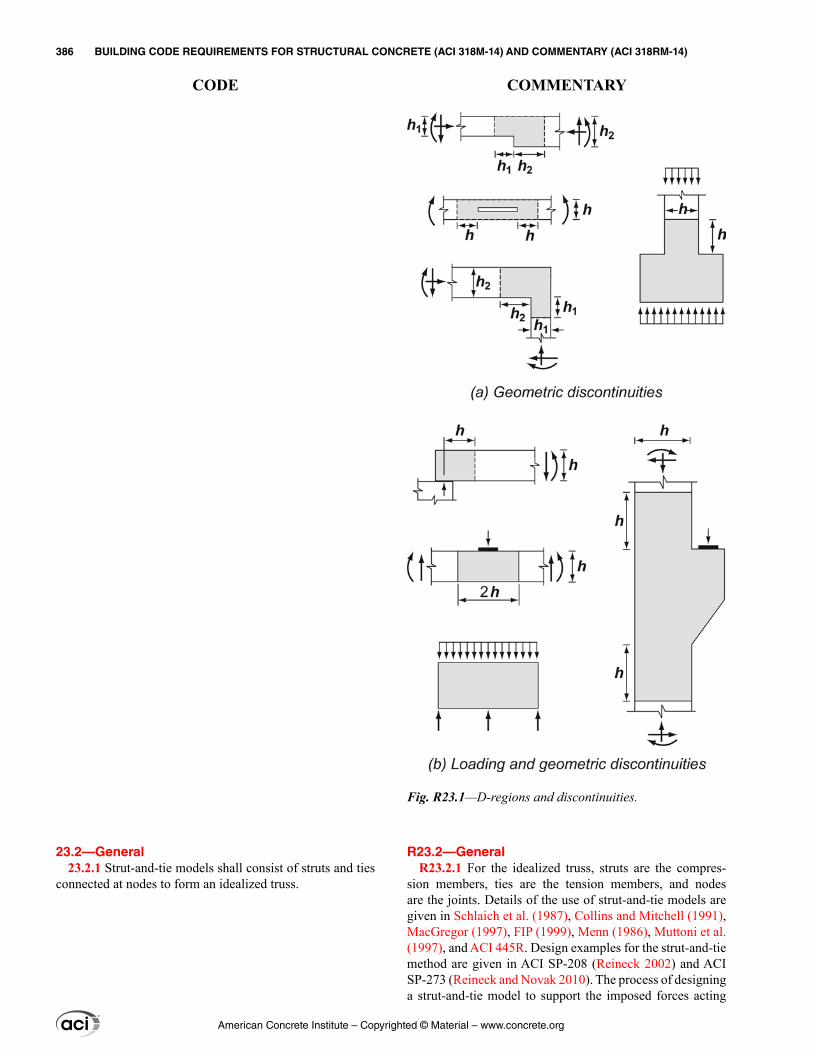
R23.2—General R23.2.1 For the idealized truss, struts are the compres-
sion members, ties are the tension members, and nodes are the joints. Details of the use of strut-and-tie models are given in Schlaich et al. (1987), Collins and Mitchell (1991), MacGregor (1997), FIP (1999), Menn (1986), Muttoni et al. (1997), and ACI 445R. Design examples for the strut-and-tie method are given in ACI SP-208 (Reineck 2002) and ACI SP-273 (Reineck and Novak 2010). The process of designing a strut-and-tie model to support the imposed forces acting
23.2—General 23.2.1 Strut-and-tie models shall consist of struts and ties
connected at nodes to form an idealized truss.
Fig. R23.1—D-regions and discontinuities.
American Concrete Institute – Copyrighted © Material – www.concrete.org
386 BUILDING CODE REQUIREMENTS FOR STRUCTURAL CONCRETE (ACI 318M-14) AND COMMENTARY (ACI 318RM-14)
CODE COMMENTARY
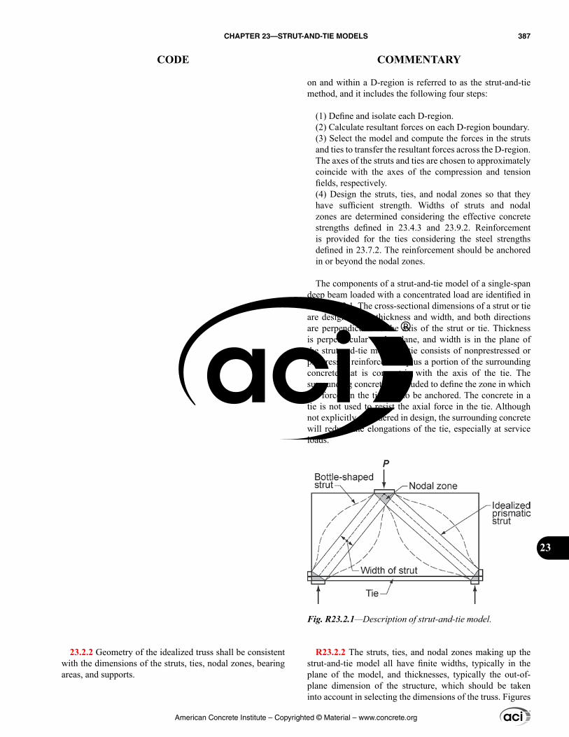
on and within a D-region is referred to as the strut-and-tie method, and it includes the following four steps:
(1) Define and isolate each D-region.(2) Calculate resultant forces on each D-region boundary.(3) Select the model and compute the forces in the struts and ties to transfer the resultant forces across the D-region. The axes of the struts and ties are chosen to approximately coincide with the axes of the compression and tension fields, respectively.(4) Design the struts, ties, and nodal zones so that they have sufficient strength. Widths of struts and nodal zones are determined considering the effective concrete strengths defined in 23.4.3 and 23.9.2. Reinforcement is provided for the ties considering the steel strengths defined in 23.7.2. The reinforcement should be anchored in or beyond the nodal zones.
The components of a strut-and-tie model of a single-span deep beam loaded with a concentrated load are identified in Fig. R23.2.1. The cross-sectional dimensions of a strut or tie are designated as thickness and width, and both directions are perpendicular to the axis of the strut or tie. Thickness is perpendicular to the plane, and width is in the plane of the strut-and-tie model. A tie consists of nonprestressed or prestressed reinforcement plus a portion of the surrounding concrete that is concentric with the axis of the tie. The surrounding concrete is included to define the zone in which the forces in the ties are to be anchored. The concrete in a tie is not used to resist the axial force in the tie. Although not explicitly considered in design, the surrounding concrete will reduce the elongations of the tie, especially at service loads.
R23.2.2 The struts, ties, and nodal zones making up the strut-and-tie model all have finite widths, typically in the plane of the model, and thicknesses, typically the out-of-plane dimension of the structure, which should be taken into account in selecting the dimensions of the truss. Figures
23.2.2 Geometry of the idealized truss shall be consistent with the dimensions of the struts, ties, nodal zones, bearing areas, and supports.
Fig. R23.2.1—Description of strut-and-tie model.
American Concrete Institute – Copyrighted © Material – www.concrete.org
CHAPTER 23—STRUT-AND-TIE MODELS 387
CODE COMMENTARY
23
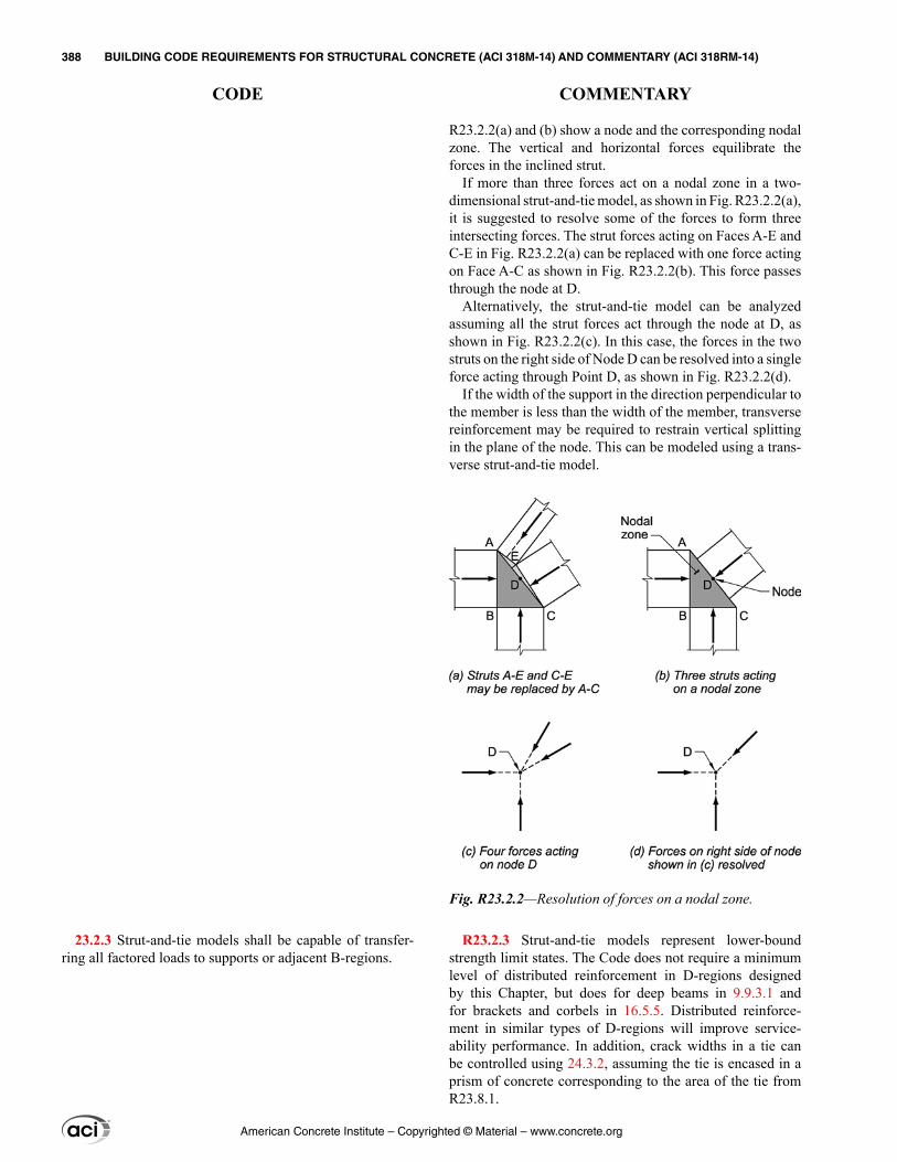
R23.2.2(a) and (b) show a node and the corresponding nodal zone. The vertical and horizontal forces equilibrate the forces in the inclined strut.
If more than three forces act on a nodal zone in a two-dimensional strut-and-tie model, as shown in Fig. R23.2.2(a), it is suggested to resolve some of the forces to form three intersecting forces. The strut forces acting on Faces A-E and C-E in Fig. R23.2.2(a) can be replaced with one force acting on Face A-C as shown in Fig. R23.2.2(b). This force passes through the node at D.
Alternatively, the strut-and-tie model can be analyzed assuming all the strut forces act through the node at D, as shown in Fig. R23.2.2(c). In this case, the forces in the two struts on the right side of Node D can be resolved into a single force acting through Point D, as shown in Fig. R23.2.2(d).
If the width of the support in the direction perpendicular to the member is less than the width of the member, transverse reinforcement may be required to restrain vertical splitting in the plane of the node. This can be modeled using a trans-verse strut-and-tie model.
R23.2.3 Strut-and-tie models represent lower-bound strength limit states. The Code does not require a minimum level of distributed reinforcement in D-regions designed by this Chapter, but does for deep beams in 9.9.3.1 and for brackets and corbels in 16.5.5. Distributed reinforce-ment in similar types of D-regions will improve service-ability performance. In addition, crack widths in a tie can be controlled using 24.3.2, assuming the tie is encased in a prism of concrete corresponding to the area of the tie from R23.8.1.
23.2.3 Strut-and-tie models shall be capable of transfer-ring all factored loads to supports or adjacent B-regions.
Fig. R23.2.2—Resolution of forces on a nodal zone.
American Concrete Institute – Copyrighted © Material – www.concrete.org
388 BUILDING CODE REQUIREMENTS FOR STRUCTURAL CONCRETE (ACI 318M-14) AND COMMENTARY (ACI 318RM-14)
CODE COMMENTARY
R23.2.6 A hydrostatic nodal zone, by definition, has equal stresses on the loaded faces; these faces are perpendicular to the axes of the struts and ties that act on the node. This type of node is considered a hydrostatic nodal zone because the in-plane stresses are the same in all directions. Strictly speaking, this terminology is incorrect because the in-plane stresses are not equal to the out-of-plane stresses.
Figure R23.2.6a(i) shows a C-C-C nodal zone. If the stresses on the face of the nodal zone are the same in all three struts, the ratios of the lengths of the sides of the nodal zone, wn1:wn2:wn3, are in the same proportions as the three forces, C1:C2:C3.
A C-C-T nodal zone can be represented as a hydrostatic nodal zone if the tie is assumed to extend through the node and is anchored by a plate on the far side of the node, as shown in Fig. R23.2.6a(ii), provided that the size of the plate results in bearing stresses that are equal to the stresses in the struts. The bearing plate on the left side of Fig. R23.2.6a(ii) is used to represent an actual tie anchorage. The tie force can be anchored by a plate or through embedment of straight bars (Fig. R23.2.6a(iii)), headed bars, or hooked bars. For non-hydrostatic nodes, the face with the highest stress will control the dimensions of the node.
The lightly shaded area in Fig. R23.2.6a(ii) is an extended nodal zone. An extended nodal zone is that portion of a member bounded by the intersection of the effective strut width ws and the effective tie width wt.
For equilibrium, at least three forces should act on each node in a strut-and-tie model, as shown in Fig. R23.2.6c. Nodes are classified according to the signs of these forces. A C-C-C node resists three compressive forces, a C-C-T node resists two compressive forces and one tensile force, and a C-T-T node resists one compressive force and two tensile forces.
23.2.4 The internal forces in strut-and-tie models shall be in equilibrium with the applied loads and reactions.
23.2.5 Ties shall be permitted to cross struts and other ties.
23.2.6 Struts shall intersect or overlap only at nodes.
American Concrete Institute – Copyrighted © Material – www.concrete.org
CHAPTER 23—STRUT-AND-TIE MODELS 389
CODE COMMENTARY
23
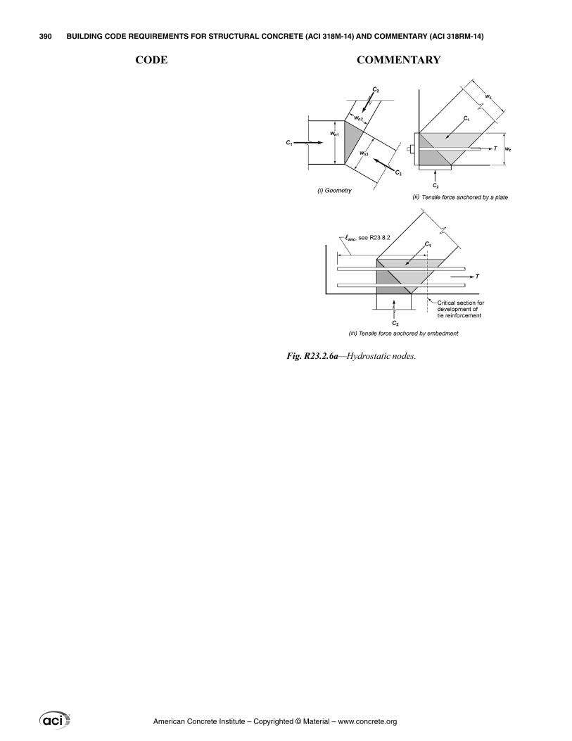
Fig. R23.2.6a—Hydrostatic nodes.
American Concrete Institute – Copyrighted © Material – www.concrete.org
390 BUILDING CODE REQUIREMENTS FOR STRUCTURAL CONCRETE (ACI 318M-14) AND COMMENTARY (ACI 318RM-14)
CODE COMMENTARY
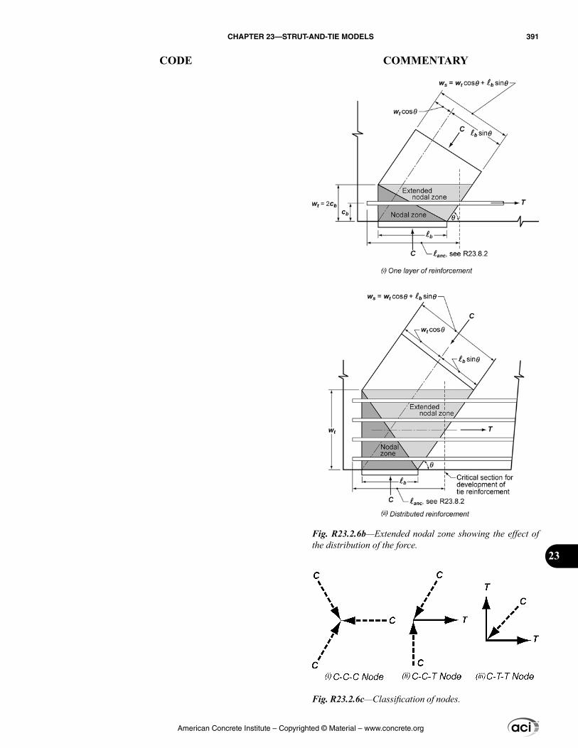
Fig. R23.2.6b—Extended nodal zone showing the effect of the distribution of the force.
Fig. R23.2.6c—Classification of nodes.
American Concrete Institute – Copyrighted © Material – www.concrete.org
CHAPTER 23—STRUT-AND-TIE MODELS 391
CODE COMMENTARY
23
23.2.7 The angle between the axes of any strut and any tie entering a single node shall be at least 25 degrees.
23.2.8 Deep beams designed using strut-and-tie models shall satisfy 9.9.2.1, 9.9.3.1, and 9.9.4.
23.2.9 Brackets and corbels with shear span-to-depth ratio av/d < 2.0 designed using strut-and-tie models shall satisfy 16.5.2, 16.5.6, and Eq. (23.2.9).
Asc ≥ 0.04(fc′/fy)(bwd) (23.2.9)
23.3—Design strength 23.3.1 For each applicable factored load combination,
design strength of each strut, tie, and nodal zone in a strut-and-tie model shall satisfy ϕSn ≥ U, including (a) through (c):
(a) Struts: ϕFns ≥ Fus (b) Ties: ϕFnt ≥ Fut (c) Nodal zones: ϕFnn ≥ Fus
23.3.2 ϕ shall be in accordance with 21.2.
23.4—Strength of struts 23.4.1 The nominal compressive strength of a strut, Fns,
shall be calculated by (a) or (b):
(a) Strut without longitudinal reinforcement
Fns = fceAcs (23.4.1a)
(b) Strut with longitudinal reinforcement
Fns = fceAcs + As′fs′ (23.4.1b)
where Fns shall be evaluated at each end of the strut and taken as the lesser value; Acs is the cross-sectional area at the end of the strut under consideration; fce is given in 23.4.3; As′ is the area of compression reinforcement along the length of the strut; and fs′ is the stress in the compres-sion reinforcement at the nominal axial strength of the strut. It shall be permitted to take fs′ equal to fy for Grade 40 or 60 reinforcement.
23.4.2 Effective compressive strength of concrete in a strut, fce, shall be calculated in accordance with 23.4.3 or 23.4.4.
R23.2.7 The angle between the axes of a strut and a tie acting on a node should be large enough to mitigate cracking and to avoid incompatibilities due to shortening of the strut and lengthening of the tie occurring in approximately the same direction. This limitation on the angle prevents modeling shear spans in slender beams using struts inclined at less than 25 degrees from the longitudinal reinforcement (Muttoni et al. 1997).
R23.3—Design strength R23.3.1 Factored loads are applied to the strut-and-tie
model, and the forces in all the struts, ties, and nodal zones are calculated. If several load combinations exist, each should be investigated separately. For a given strut, tie, or nodal zone, Fu is the largest force in that element for all load combinations considered.
R23.4—Strength of struts R23.4.1 The width of strut, ws, used to calculate Acs is the
dimension perpendicular to the axis of the strut at the ends of the strut. This strut width is illustrated in Fig. R23.2.6a(i) and Fig. R23.2.6b. If two-dimensional strut-and-tie models are appropriate, such as for deep beams, the thickness of the struts may be taken as the width of the member except at bearing supports where the thickness of the strut must equal the least thickness of the member or supporting element.
The contribution of reinforcement to the strength of the strut is given by the last term in Eq. (23.4.1b). The stress fs′ in the reinforcement in a strut at nominal strength can be obtained from the strains in the strut when the strut crushes. Detailing requirements in 23.6 must be met including confinement rein-forcement to prevent buckling of the strut reinforcement.
R23.4.2 In design, struts are usually idealized as prismatic compression members. If the area of a strut differs at its two ends, due either to different nodal zone strengths at the two ends or to different bearing lengths, the strut is idealized as a uniformly tapered compression member.
American Concrete Institute – Copyrighted © Material – www.concrete.org
392 BUILDING CODE REQUIREMENTS FOR STRUCTURAL CONCRETE (ACI 318M-14) AND COMMENTARY (ACI 318RM-14)
CODE COMMENTARY
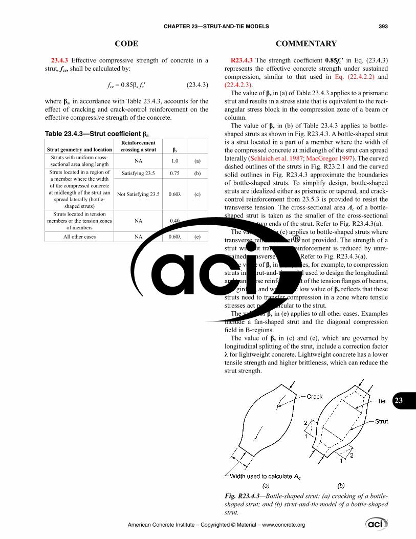
23.4.3 Effective compressive strength of concrete in a strut, fce, shall be calculated by:
fce = 0.85βs fc′ (23.4.3)
where βs, in accordance with Table 23.4.3, accounts for the effect of cracking and crack-control reinforcement on the effective compressive strength of the concrete.
Table 23.4.3—Strut coefficient βs
Strut geometry and locationReinforcement crossing a strut βs
Struts with uniform cross-sectional area along length NA 1.0 (a)
Struts located in a region of a member where the width of the compressed concrete at midlength of the strut can
spread laterally (bottle-shaped struts)
Satisfying 23.5 0.75 (b)
Not Satisfying 23.5 0.60λ (c)
Struts located in tension members or the tension zones
of membersNA 0.40 (d)
All other cases NA 0.60λ (e)
R23.4.3 The strength coefficient 0.85fc′ in Eq. (23.4.3) represents the effective concrete strength under sustained compression, similar to that used in Eq. (22.4.2.2) and (22.4.2.3).
The value of βs in (a) of Table 23.4.3 applies to a prismatic strut and results in a stress state that is equivalent to the rect-angular stress block in the compression zone of a beam or column.
The value of βs in (b) of Table 23.4.3 applies to bottle-shaped struts as shown in Fig. R23.4.3. A bottle-shaped strut is a strut located in a part of a member where the width of the compressed concrete at midlength of the strut can spread laterally (Schlaich et al. 1987; MacGregor 1997). The curved dashed outlines of the struts in Fig. R23.2.1 and the curved solid outlines in Fig. R23.4.3 approximate the boundaries of bottle-shaped struts. To simplify design, bottle-shaped struts are idealized either as prismatic or tapered, and crack-control reinforcement from 23.5.3 is provided to resist the transverse tension. The cross-sectional area Ac of a bottle-shaped strut is taken as the smaller of the cross-sectional areas at the two ends of the strut. Refer to Fig. R23.4.3(a).
The value of βs in (c) applies to bottle-shaped struts where transverse reinforcement is not provided. The strength of a strut without transverse reinforcement is reduced by unre-strained transverse tension. Refer to Fig. R23.4.3(a).
The value of βs in (d) applies, for example, to compression struts in a strut-and-tie model used to design the longitudinal and transverse reinforcement of the tension flanges of beams, box girders, and walls. The low value of βs reflects that these struts need to transfer compression in a zone where tensile stresses act perpendicular to the strut.
The value of βs in (e) applies to all other cases. Examples include a fan-shaped strut and the diagonal compression field in B-regions.
The value of βs in (c) and (e), which are governed by longitudinal splitting of the strut, include a correction factor λ for lightweight concrete. Lightweight concrete has a lower tensile strength and higher brittleness, which can reduce the strut strength.
Fig. R23.4.3—Bottle-shaped strut: (a) cracking of a bottle-shaped strut; and (b) strut-and-tie model of a bottle-shaped strut.
American Concrete Institute – Copyrighted © Material – www.concrete.org
CHAPTER 23—STRUT-AND-TIE MODELS 393
CODE COMMENTARY
23
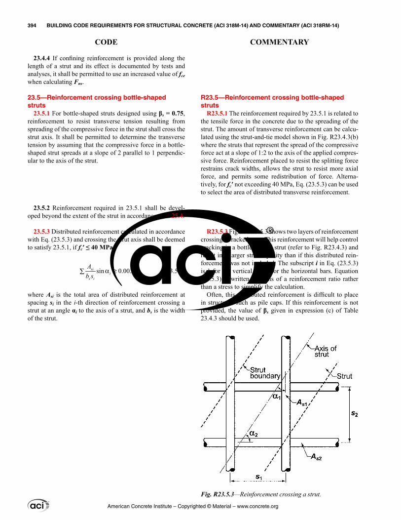
23.4.4 If confining reinforcement is provided along the length of a strut and its effect is documented by tests and analyses, it shall be permitted to use an increased value of fce when calculating Fns.
23.5—Reinforcement crossing bottle-shaped struts
23.5.1 For bottle-shaped struts designed using βs = 0.75, reinforcement to resist transverse tension resulting from spreading of the compressive force in the strut shall cross the strut axis. It shall be permitted to determine the transverse tension by assuming that the compressive force in a bottle-shaped strut spreads at a slope of 2 parallel to 1 perpendic-ular to the axis of the strut.
23.5.2 Reinforcement required in 23.5.1 shall be devel-oped beyond the extent of the strut in accordance with 25.4.
23.5.3 Distributed reinforcement calculated in accordance with Eq. (23.5.3) and crossing the strut axis shall be deemed to satisfy 23.5.1, if fc′ ≤ 40 MPa.
sin 0.003sii
s i
Ab s
α ≥∑ (23.5.3)
where Asi is the total area of distributed reinforcement at spacing si in the i-th direction of reinforcement crossing a strut at an angle αi to the axis of a strut, and bs is the width of the strut.
R23.5—Reinforcement crossing bottle-shaped struts
R23.5.1 The reinforcement required by 23.5.1 is related to the tensile force in the concrete due to the spreading of the strut. The amount of transverse reinforcement can be calcu-lated using the strut-and-tie model shown in Fig. R23.4.3(b) where the struts that represent the spread of the compressive force act at a slope of 1:2 to the axis of the applied compres-sive force. Reinforcement placed to resist the splitting force restrains crack widths, allows the strut to resist more axial force, and permits some redistribution of force. Alterna-tively, for fc′ not exceeding 40 MPa, Eq. (23.5.3) can be used to select the area of distributed transverse reinforcement.
R23.5.3 Figure R23.5.3 shows two layers of reinforcement crossing a cracked strut. This reinforcement will help control cracking in a bottle-shaped strut (refer to Fig. R23.4.3) and result in a larger strut capacity than if this distributed rein-forcement was not included. The subscript i in Eq. (23.5.3) is 1 for the vertical and 2 for the horizontal bars. Equation (23.5.3) is written in terms of a reinforcement ratio rather than a stress to simplify the calculation.
Often, this distributed reinforcement is difficult to place in structures such as pile caps. If this reinforcement is not provided, the value of βs given in expression (c) of Table 23.4.3 should be used.
Fig. R23.5.3—Reinforcement crossing a strut.
American Concrete Institute – Copyrighted © Material – www.concrete.org
394 BUILDING CODE REQUIREMENTS FOR STRUCTURAL CONCRETE (ACI 318M-14) AND COMMENTARY (ACI 318RM-14)
CODE COMMENTARY
R23.5.3.1 An important example of the application of 23.5.3.1 is for a corbel with a shear span-to-depth ratio less than 1.0, for which the distributed reinforcement required to satisfy 23.5.1 is usually provided in the form of horizontal stirrups crossing the inclined compression strut, as shown in Fig. R16.5.1b.
R23.6—Strut reinforcement detailing R23.6.1 Refer to R23.4.1.
R23.6.3.3 Refer to R25.7.2.3.
23.5.3.1 Distributed reinforcement required in 23.5.3 shall be placed orthogonally at angles α1 and α2 to the axis of the strut, or in one direction at an angle α1 to the axis of the strut. Where the reinforcement is placed in only one direction, α1 shall be at least 40 degrees.
23.6—Strut reinforcement detailing 23.6.1 Compression reinforcement in struts shall be
parallel to the axis of the strut and enclosed along the length of the strut by closed ties in accordance with 23.6.3 or by spirals in accordance with 23.6.4.
23.6.2 Compression reinforcement in struts shall be anchored to develop fs′ at the face of the nodal zone, where fs′ is calculated in accordance with 23.4.1.
23.6.3 Closed ties enclosing compression reinforcement in struts shall satisfy 25.7.2 and this section.
23.6.3.1 Spacing of closed ties, s, along the length of the strut shall not exceed the smallest of (a) through (c):
(a) Smallest dimension of cross section of strut(b) 48db of bar or wire used for closed tie reinforcement(c) 16db of compression reinforcement
23.6.3.2 The first closed tie shall be located not more than 0.5s from the face of the nodal zone at each end of a strut.
23.6.3.3 Closed ties shall be arranged such that every corner and alternate longitudinal bar shall have lateral support provided by crossties or the corner of a tie with an included angle of not more than 135 degrees and no longi-tudinal bar shall be farther than 150 mm clear on each side along the tie from such a laterally supported bar.
23.6.4 Spirals enclosing compression reinforcement in struts shall satisfy 25.7.3.
23.7—Strength of ties 23.7.1 Tie reinforcement shall be nonprestressed or
prestressed.
23.7.2 The nominal tensile strength of a tie, Fnt, shall be calculated by:
Fnt = Ats fy + Atp(fse + ∆fp) (23.7.2)
where (fse + ∆fp) shall not exceed fpy, and Atp is zero for nonprestressed members.
23.7.3 In Eq. (23.7.2), it shall be permitted to take ∆fp equal to 420 MPa for bonded prestressed reinforcement and 70 MPa for unbonded prestressed reinforcement. Higher values of ∆fp shall be permitted if justified by analysis.
American Concrete Institute – Copyrighted © Material – www.concrete.org
CHAPTER 23—STRUT-AND-TIE MODELS 395
CODE COMMENTARY
23
R23.8—Tie reinforcement detailing R23.8.1 The effective tie width assumed in design, wt, can
vary between the following limits, depending on the distri-bution of the tie reinforcement:
(a) If the bars in the tie are in one layer, the effective tie width can be taken as the diameter of the bars in the tie plus twice the cover to the surface of the bars, as shown in Fig. R23.2.6b(i).(b) A practical upper limit of the tie width can be taken as the width corresponding to the width in a hydrostatic nodal zone, calculated as wt,max = Fnt/(fcebs), where fce is calculated for the nodal zone in accordance with 23.9.2.
If the tie width exceeds the value from (a), the tie rein-forcement should be distributed approximately uniformly over the width and thickness of the tie, as shown in Fig. R23.2.6b(ii).
R23.8.2 Anchorage of ties often requires special atten-tion in nodal zones of corbels or in nodal zones adjacent to exterior supports of deep beams. The reinforcement in a tie should be anchored before it exits the extended nodal zone at the point defined by the intersection of the centroid of the bars in the tie and the extensions of the outlines of either the strut or the bearing area. This length is ℓanc. In Fig. R23.2.6b, this occurs where the outline of the extended nodal zone is crossed by the centroid of the reinforcement in the tie. Some of the anchorage may be achieved by extending the reinforce-ment through the nodal zone, as shown in Fig. R23.2.6a(iii) and R23.2.6b, and developing it beyond the nodal zone. If the tie is anchored using 90-degree hooks, the hooks should be confined within reinforcement to avoid cracking along the outside of the hooks in the support region.
In deep beams, hairpin bars spliced with the tie reinforce-ment can be used to anchor the tie forces at exterior supports, provided the beam width is large enough to accommodate such bars.
Figure R23.8.2 shows two ties anchored at a nodal zone. Development is required where the centroid of the tie crosses the outline of the extended nodal zone.
The development length of the tie reinforcement can be reduced through hooks, headed bars, mechanical devices, additional confinement, or by splicing it with layers of smaller bars.
23.8—Tie reinforcement detailing 23.8.1 The centroidal axis of the tie reinforcement shall
coincide with the axis of the tie assumed in the strut-and-tie model.
23.8.2 Tie reinforcement shall be anchored by mechanical devices, post-tensioning anchorage devices, standard hooks, or straight bar development in accordance with 23.8.3.
23.8.3 Tie reinforcement shall be developed in accordance with (a) or (b):
(a) The difference between the tie force on one side of a node and the tie force on the other side shall be developed within the nodal zone.(b) At nodal zones anchoring one or more ties, the tie force in each direction shall be developed at the point where the centroid of the reinforcement in the tie leaves the extended nodal zone.
American Concrete Institute – Copyrighted © Material – www.concrete.org
396 BUILDING CODE REQUIREMENTS FOR STRUCTURAL CONCRETE (ACI 318M-14) AND COMMENTARY (ACI 318RM-14)
CODE COMMENTARY
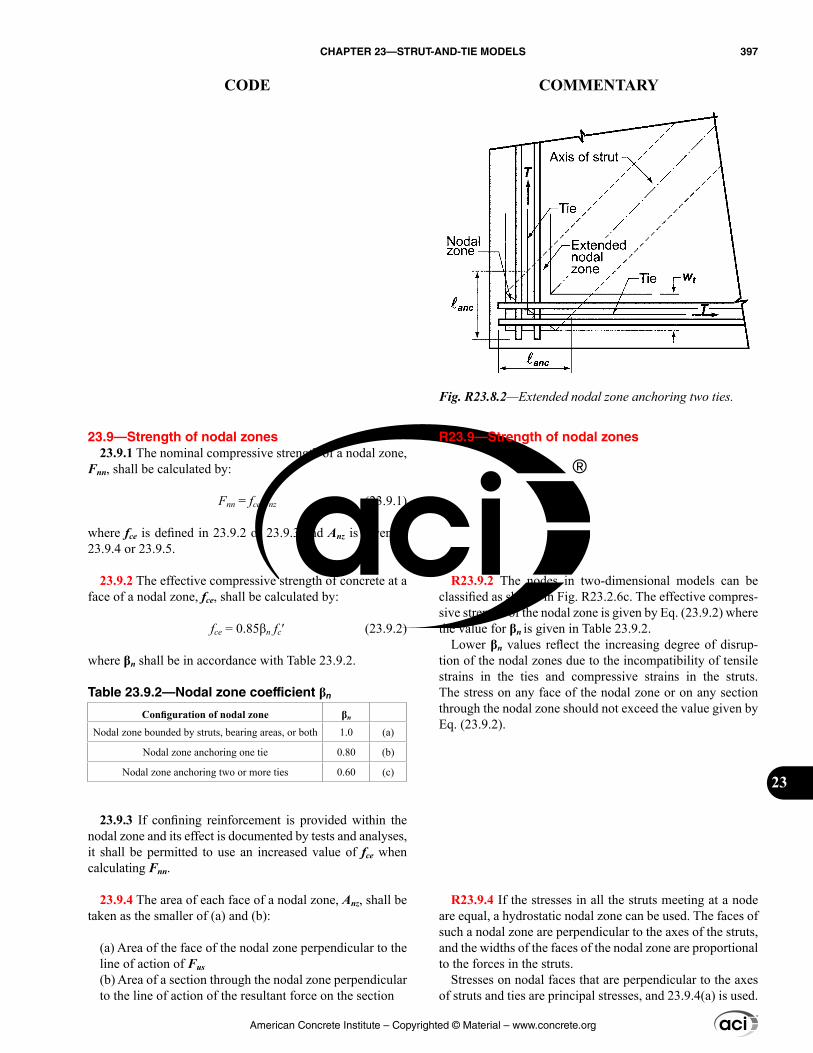
R23.9—Strength of nodal zones
R23.9.2 The nodes in two-dimensional models can be classified as shown in Fig. R23.2.6c. The effective compres-sive strength of the nodal zone is given by Eq. (23.9.2) where the value for βn is given in Table 23.9.2.
Lower βn values reflect the increasing degree of disrup-tion of the nodal zones due to the incompatibility of tensile strains in the ties and compressive strains in the struts. The stress on any face of the nodal zone or on any section through the nodal zone should not exceed the value given by Eq. (23.9.2).
R23.9.4 If the stresses in all the struts meeting at a node are equal, a hydrostatic nodal zone can be used. The faces of such a nodal zone are perpendicular to the axes of the struts, and the widths of the faces of the nodal zone are proportional to the forces in the struts.
Stresses on nodal faces that are perpendicular to the axes of struts and ties are principal stresses, and 23.9.4(a) is used.
23.9—Strength of nodal zones 23.9.1 The nominal compressive strength of a nodal zone,
Fnn, shall be calculated by:
Fnn = fceAnz (23.9.1)
where fce is defined in 23.9.2 or 23.9.3 and Anz is given in 23.9.4 or 23.9.5.
23.9.2 The effective compressive strength of concrete at a face of a nodal zone, fce, shall be calculated by:
fce = 0.85βn fc′ (23.9.2)
where βn shall be in accordance with Table 23.9.2.
Table 23.9.2—Nodal zone coefficient βn
Configuration of nodal zone βn
Nodal zone bounded by struts, bearing areas, or both 1.0 (a)
Nodal zone anchoring one tie 0.80 (b)
Nodal zone anchoring two or more ties 0.60 (c)
23.9.3 If confining reinforcement is provided within the nodal zone and its effect is documented by tests and analyses, it shall be permitted to use an increased value of fce when calculating Fnn.
23.9.4 The area of each face of a nodal zone, Anz, shall be taken as the smaller of (a) and (b):
(a) Area of the face of the nodal zone perpendicular to the line of action of Fus(b) Area of a section through the nodal zone perpendicular to the line of action of the resultant force on the section
Fig. R23.8.2—Extended nodal zone anchoring two ties.
American Concrete Institute – Copyrighted © Material – www.concrete.org
CHAPTER 23—STRUT-AND-TIE MODELS 397
CODE COMMENTARY
23
If, as shown in Fig. R23.2.6b(ii), the face of a nodal zone is not perpendicular to the axis of the strut, there will be both shear stresses and normal stresses on the face of the nodal zone. Typically, these stresses are replaced by the normal (principal compressive) stress acting on the cross-sectional area, Anz, of the strut, taken perpendicular to the axis of the strut as given in 23.9.4(a).
23.9.5 In a three-dimensional strut-and-tie model, the area of each face of a nodal zone shall be at least that given in 23.9.4, and the shape of each face of the nodal zone shall be similar to the shape of the projection of the end of the strut onto the corresponding face of the nodal zone.
American Concrete Institute – Copyrighted © Material – www.concrete.org
398 BUILDING CODE REQUIREMENTS FOR STRUCTURAL CONCRETE (ACI 318M-14) AND COMMENTARY (ACI 318RM-14)
CODE COMMENTARY
CHAPTER 24—SERVICEABILITY REQUIREMENTS
24.1—Scope 24.1.1 This chapter shall apply to member design for
minimum serviceability, including (a) through (d):
(a) Deflections due to service-level gravity loads (24.2)(b) Distribution of flexural reinforcement in one-way slabs and beams to control cracking (24.3)(c) Shrinkage and temperature reinforcement (24.4)(d) Permissible stresses in prestressed flexural members (24.5)
24.2—Deflections due to service-level gravity loads
24.2.1 Members subjected to flexure shall be designed with adequate stiffness to limit deflections or deformations that adversely affect strength or serviceability of a structure.
24.2.2 Deflections calculated in accordance with 24.2.3 through 24.2.5 shall not exceed the limits in Table 24.2.2.
R24—SERVICEABILITY REQUIREMENTS
R24.1—Scope This chapter prescribes serviceability requirements that
are referenced by other chapters of the Code, or are other-wise applicable to provide adequate performance of struc-tural members. This chapter does not stand on its own as a complete and cohesive compilation of serviceability require-ments for the design of structural members.
R24.2—Deflections due to service-level gravity loads
This section is concerned only with deflections or defor-mations that may occur at service load levels. When time-dependent deflections are calculated, only the dead load and those portions of other loads that are sustained need be considered.
Two methods are given in the Code for controlling deflec-tions (Sabnis et al. 1974). For nonprestressed one-way slabs and beams, including composite members, the minimum overall thickness required by 7.3.1 and 9.3.1 is considered to satisfy the requirements of the Code for members not supporting or attached to nonstructural elements likely to be damaged by large deflections. For nonprestressed two-way construction, the minimum thickness required by 8.3.1 is considered to satisfy the requirements of the Code.
For nonprestressed members that do not meet these minimum thickness requirements, for nonprestressed one-way members that support or are attached to nonstruc-tural elements likely to be damaged by large deflections, and for prestressed flexural members, deflections are required to be calculated by 24.2.3 through 24.2.5. Calculated deflec-tions are limited to the values in Table 24.2.2.
R24.2.2 It should be noted that the limitations given in Table 24.2.2 relate only to supported or attached nonstruc-tural elements. For those structures in which structural members are likely to be affected by deflection or defor-mation of members to which they are attached in such a manner as to affect adversely the strength of the structure, these deflections and the resulting forces should be consid-ered explicitly in the analysis and design of the structures as required by 24.2.1 (ACI 209R-92).
When time-dependent deflections are calculated, the portion of the deflection before attachment of the nonstruc-tural elements may be deducted. In making this correction, use may be made of the curve in Fig. R24.2.4.1 for members of usual sizes and shapes.
American Concrete Institute – Copyrighted © Material – www.concrete.org
CHAPTER 24—SERVICEABILITY REQUIREMENTS 399
CODE COMMENTARY
24
R24.2.3 Calculation of immediate deflections
R24.2.3.1 For calculation of immediate deflections of uncracked prismatic members, the usual methods or formulas for elastic deflections may be used with a constant value of EcIg along the length of the member. However, if the member is expected to crack at one or more sections, or if its depth varies along the span, a more rigorous calculation becomes necessary.
R24.2.3.3 The calculation of deflections for two-way slabs is challenging even if linear elastic behavior can be assumed. For immediate deflections, the values of Ec and Ie specified in 24.2.3.4 and 24.2.3.5, respectively, may be used (ACI 209R). However, other procedures and other values of the stiffness EcIe may be used if they result in predictions of deflection in reasonable agreement with the results of comprehensive tests.
R24.2.3.5 The effective moment of inertia procedure described in the Code and developed in Branson (1965) was selected as being sufficiently accurate to estimate deflections (ACI Committee 435 1966, 1968; ACI 209R). The effective moment of inertia, Ie, was developed to provide a transition between the upper and lower bounds of Ig and Icr as a func-tion of the ratio Mcr/Ma.
24.2.3 Calculation of immediate deflections
24.2.3.1 Immediate deflections shall be calculated using methods or formulas for elastic deflections, considering effects of cracking and reinforcement on member stiffness.
24.2.3.2 Effect of variation of cross-sectional properties, such as haunches, shall be considered when calculating deflections.
24.2.3.3 Deflections in two-way slab systems shall be calculated taking into account size and shape of the panel, conditions of support, and nature of restraints at the panel edges.
24.2.3.4 Modulus of elasticity, Ec, shall be permitted to be calculated in accordance with 19.2.2.
24.2.3.5 For nonprestressed members, effective moment of inertia, Ie, shall be calculated by Eq. (24.2.3.5a) unless obtained by a more comprehensive analysis, but Ie shall not be greater than Ig.
3 3
1cr cre g cr
a a
M MI I I
M M
= + −
(24.2.3.5a)
where Mcr is calculated by
r gcr
t
f IM
y= (24.2.3.5b)
Table 24.2.2—Maximum permissible calculated deflections
Member Condition Deflection to be consideredDeflection limitation
Flat roofs Not supporting or attached to nonstructural elements likely to be damaged by large deflections
Immediate deflection due to maximum of Lr, S, and R ℓ/180[1]
Floors Immediate deflection due to L ℓ/360
Roof or floors
Supporting or attached to non-structural elements
Likely to be damaged by large deflections
That part of the total deflection occurring after attachment of nonstructural elements, which is the sum of the time-depen-dent deflection due to all sustained loads and the immediate
deflection due to any additional live load[2]
ℓ/480[3]
Not likely to be damaged by large deflections ℓ/240[4]
[1]Limit not intended to safeguard against ponding. Ponding shall be checked by calculations of deflection, including added deflections due to ponded water, and considering time-dependent effects of sustained loads, camber, construction tolerances, and reliability of provisions for drainage.[2]Time-dependent deflection shall be calculated in accordance with 24.2.4, but shall be permitted to be reduced by amount of deflection calculated to occur before attachment of nonstructural elements. This amount shall be calculated on basis of accepted engineering data relating to time-deflection characteristics of members similar to those being considered.[3]Limit shall be permitted to be exceeded if measures are taken to prevent damage to supported or attached elements.[4]Limit shall not exceed tolerance provided for nonstructural elements.
American Concrete Institute – Copyrighted © Material – www.concrete.org
400 BUILDING CODE REQUIREMENTS FOR STRUCTURAL CONCRETE (ACI 318M-14) AND COMMENTARY (ACI 318RM-14)
CODE COMMENTARY
R24.2.3.7 The use of the midspan section properties for continuous prismatic members is considered satisfactory in approximate calculations primarily because the midspan stiffness (including the effect of cracking) has the domi-nant effect on deflections, as shown by ACI 435.5R, ACI Committee 435 (1978), and Sabnis et al. (1974).
R24.2.3.8 Immediate deflections of Class U prestressed concrete members may be calculated by the usual methods or formulas for elastic deflections using the moment of inertia of the gross (uncracked) concrete section and the modulus of elasticity for concrete specified in 19.2.2.1.
R24.2.3.9 Class C and Class T prestressed flexural members are defined in 24.5.2. The PCI Design Handbook (PCI MNL 120) gives information on deflection calculations using a bilinear moment-deflection relationship and using an effective moment of inertia. Mast (1998) gives additional information on deflection of cracked prestressed concrete members.
Shaikh and Branson (1970) shows that the Ie method can be used to calculate deflections of Class C and Class T prestressed members loaded above the cracking load. For this case, the cracking moment should take into account the effect of prestress as provided in Eq. (24.2.3.9).
A method for predicting the effect of nonprestressed tension reinforcement in reducing creep camber is also given in Shaikh and Branson (1970), with approximate forms given in ACI 209R and Branson (1970).
R24.2.4 Calculation of time-dependent deflections
R24.2.4.1 Nonprestressed members—Shrinkage and creep cause time-dependent deflections in addition to the elastic deflections that occur when loads are first placed on the structure. Such deflections are influenced by tempera-ture, humidity, curing conditions, age at time of loading, amount of compression reinforcement, and magnitude of the sustained load. The expression given in this section is considered satisfactory for use with the Code procedures for the calculation of immediate deflections, and with the limits given in Table 24.2.2. The deflection calculated in accor-dance with this section is the additional time-dependent deflection due to the dead load and those portions of other loads that will be sustained for a sufficient period to cause significant time-dependent deflections.
Equation (24.2.4.1.1) was developed in Branson (1971). In Eq. (24.2.4.1.1), the term (1 + 50ρ′) accounts for the effect of compression reinforcement in reducing time-dependent deflections. ξ = 2.0 represents a nominal time-dependent factor for a 5-year duration of loading. The curve in Fig.
24.2.3.6 For continuous one-way slabs and beams, Ie shall be permitted to be taken as the average of values obtained from Eq. (24.2.3.5a) for the critical positive and negative moment sections.
24.2.3.7 For prismatic one-way slabs and beams, Ie shall be permitted to be taken as the value obtained from Eq. (24.2.3.5a) at midspan for simple and continuous spans, and at the support for cantilevers.
24.2.3.8 For prestressed Class U slabs and beams as defined in 24.5.2, it shall be permitted to calculate deflec-tions based on Ig.
24.2.3.9 For prestressed Class T and Class C slabs and beams as defined in 24.5.2, deflection calculations shall be based on a cracked transformed section analysis. It shall be permitted to base deflection calculations on a bilinear moment-deflection relationship or Ie in accordance with Eq. (24.2.3.5a), where Mcr is calculated as:
( )r pe g
crt
f f IM
y
+= (24.2.3.9)
24.2.4 Calculation of time-dependent deflections
24.2.4.1 Nonprestressed members
24.2.4.1.1 Unless obtained from a more comprehensive analysis, additional time-dependent deflection resulting from creep and shrinkage of flexural members shall be calculated as the product of the immediate deflection caused by sustained load and the factor λ∆
1 50∆
ξλ =
+ ρ′ (24.2.4.1.1)
24.2.4.1.2 In Eq. (24.2.4.1.1), ρ′ shall be calculated at midspan for simple and continuous spans, and at the support for cantilevers.
24.2.4.1.3 In Eq. (24.2.4.1.1), values of the time-depen-dent factor for sustained loads, ξ, shall be in accordance with Table 24.2.4.1.3.
American Concrete Institute – Copyrighted © Material – www.concrete.org
CHAPTER 24—SERVICEABILITY REQUIREMENTS 401
CODE COMMENTARY
24
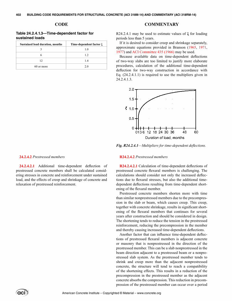
R24.2.4.1 may be used to estimate values of ξ for loading periods less than 5 years.
If it is desired to consider creep and shrinkage separately, approximate equations provided in Branson (1965, 1971, 1977) and ACI Committee 435 (1966) may be used.
Because available data on time-dependent deflections of two-way slabs are too limited to justify more elaborate procedures, calculation of the additional time-dependent deflection for two-way construction in accordance with Eq. (24.2.4.1.1) is required to use the multipliers given in 24.2.4.1.3.
R24.2.4.2 Prestressed members
R24.2.4.2.1 Calculation of time-dependent deflections of prestressed concrete flexural members is challenging. The calculations should consider not only the increased deflec-tions due to flexural stresses, but also the additional time-dependent deflections resulting from time-dependent short-ening of the flexural member.
Prestressed concrete members shorten more with time than similar nonprestressed members due to the precompres-sion in the slab or beam, which causes creep. This creep, together with concrete shrinkage, results in significant short-ening of the flexural members that continues for several years after construction and should be considered in design. The shortening tends to reduce the tension in the prestressed reinforcement, reducing the precompression in the member and thereby causing increased time-dependent deflections.
Another factor that can influence time-dependent deflec-tions of prestressed flexural members is adjacent concrete or masonry that is nonprestressed in the direction of the prestressed member. This can be a slab nonprestressed in the beam direction adjacent to a prestressed beam or a nonpre-stressed slab system. As the prestressed member tends to shrink and creep more than the adjacent nonprestressed concrete, the structure will tend to reach a compatibility of the shortening effects. This results in a reduction of the precompression in the prestressed member as the adjacent concrete absorbs the compression. This reduction in precom-pression of the prestressed member can occur over a period
Table 24.2.4.1.3—Time-dependent factor for sustained loads
Sustained load duration, months Time-dependent factor ξ
3 1.0
6 1.2
12 1.4
60 or more 2.0
24.2.4.2 Prestressed members
24.2.4.2.1 Additional time-dependent deflection of prestressed concrete members shall be calculated consid-ering stresses in concrete and reinforcement under sustained load, and the effects of creep and shrinkage of concrete and relaxation of prestressed reinforcement.
Fig. R24.2.4.1—Multipliers for time-dependent deflections.
American Concrete Institute – Copyrighted © Material – www.concrete.org
402 BUILDING CODE REQUIREMENTS FOR STRUCTURAL CONCRETE (ACI 318M-14) AND COMMENTARY (ACI 318RM-14)
CODE COMMENTARY

of years and will result in additional time-dependent deflec-tions and an increase in tensile stresses in the prestressed member.
Any suitable method for calculating time-dependent deflections of prestressed members may be used, provided all effects are considered. Guidance may be found in ACI 209R, ACI Committee 435 (1963), Branson et al. (1970), and Ghali and Favre (1986).
R24.2.5 Calculation of deflections of composite concrete construction—Composite concrete members are designed to meet the horizontal shear strength requirements of 16.4. Because few tests have been made to study the immediate and time-dependent deflections of composite members, the requirements given in this section are based on the judgment of ACI Committee 318 and on experience.
In 22.3.3.3, it is stated that distinction need not be made between shored and unshored members. This refers to strength calculations, not to deflections. Construction docu-ments should indicate whether composite concrete design is based on shored or unshored construction, as required by 26.11.1.1.
R24.3—Distribution of flexural reinforcement in one-way slabs and beams
R24.3.1 Where service loads result in high stresses in the reinforcement, visible cracks should be expected, and steps should be taken in detailing of the reinforcement to control cracking. For reasons of durability and appearance, many fine cracks are preferable to a few wide cracks. Detailing practices limiting bar spacing will usually lead to adequate crack control where Grade 420 reinforcement is used.
Extensive laboratory work (Gergely and Lutz 1968; Kaar 1966; Base et al. 1966) involving deformed bars demon-strated that crack width at service loads is proportional to reinforcement stress. The significant variables reflecting reinforcement detailing were found to be thickness of concrete cover and the spacing of reinforcement.
Crack width is inherently subject to wide scatter even in careful laboratory work and is influenced by shrinkage and other time-dependent effects. Improved crack control is obtained where the reinforcement is well distributed over the zone of maximum concrete tension. Several bars at moderate spacing are much more effective in controlling cracking than one or two larger bars of equivalent area.
24.2.5 Calculation of deflections of composite concrete construction
24.2.5.1 If composite concrete flexural members are shored during construction so that, after removal of tempo-rary supports, the dead load is resisted by the full composite section, it shall be permitted to consider the composite member equivalent to a monolithically cast member for calculation of deflections.
24.2.5.2 If composite concrete flexural members are not shored during construction, the magnitude and duration of load before and after composite action becomes effec-tive shall be considered in calculating time-dependent deflections.
24.2.5.3 Deflections resulting from differential shrinkage of precast and cast-in-place components, and of axial creep effects in prestressed members, shall be considered.
24.3—Distribution of flexural reinforcement in one-way slabs and beams
24.3.1 Bonded reinforcement shall be distributed to control flexural cracking in tension zones of nonprestressed and Class C prestressed slabs and beams reinforced for flexure in one direction only.
American Concrete Institute – Copyrighted © Material – www.concrete.org
CHAPTER 24—SERVICEABILITY REQUIREMENTS 403
CODE COMMENTARY
24
24.3.2 Spacing of bonded reinforcement closest to the tension face shall not exceed the limits in Table 24.3.2, where cc is the least distance from surface of deformed or prestressed reinforcement to the tension face. Calculated stress in deformed reinforcement, fs, and calculated change in stress in bonded prestressed reinforcement, ∆fps, shall be in accordance with 24.3.2.1 and 24.3.2.2, respectively.
Table 24.3.2—Maximum spacing of bonded reinforcement in nonprestressed and Class C prestressed one-way slabs and beams
Reinforcement type Maximum spacing s
Deformed bars or wires
Lesser of:
280380 2.5
− cs
cf
280300 sf
Bonded prestressed
reinforcement
Lesser of:
2 280380 2.53
− ∆ c
ps
cf
2 2803003
∆ psf
Combined deformed bars or wires and bonded
prestressed reinforcement
Lesser of:
5 280380 2.56
− ∆ c
ps
cf
5 2803006
∆ psf
24.3.2.1 Stress fs in deformed reinforcement closest to the tension face at service loads shall be calculated based on the unfactored moment, or it shall be permitted to take fs as (2/3)fy.
24.3.2.2 Change in stress, ∆fps, in bonded prestressed rein-forcement at service loads shall be equal to the calculated stress based on a cracked section analysis minus the decom-pression stress fdc. It shall be permitted to take fdc equal to the effective stress in the prestressed reinforcement fse. The value of ∆fps shall not exceed 250 MPa. If ∆fps does not exceed 140 MPa, the spacing limits in Table 24.3.2 need not be satisfied.
24.3.3 If there is only one bonded bar, pretensioned strand, or bonded tendon nearest to the extreme tension face, the width of the extreme tension face shall not exceed s deter-mined in accordance with Table 24.3.2.
24.3.4 If flanges of T-beams are in tension, part of the bonded flexural tension reinforcement shall be distributed over an effective flange width as defined in accordance with 6.3.2, but not wider than ℓn/10. If the effective flange width exceeds ℓn/10, additional bonded longitudinal reinforcement shall be provided in the outer portions of the flange.
R24.3.2 The spacing of reinforcement is limited to control cracking (Beeby 1979; Frosch 1999; ACI Committee 318 1999). For the case of beams with Grade 420 reinforcement and 50 mm clear cover to the primary reinforcement, with fs = 280 MPa, the maximum bar spacing is 250 mm.
Crack widths in structures are highly variable. The Code provisions for spacing are intended to limit surface cracks to a width that is generally acceptable in practice but may vary widely in a given structure.
The role of cracks in the corrosion of reinforcement is controversial. Research (Darwin et al. 1985; Oesterle 1997) shows that corrosion is not clearly correlated with surface crack widths in the range normally found with reinforcement stresses at service load levels. For this reason, the Code does not differentiate between interior and exterior exposures.
Only tension reinforcement nearest the tension face need be considered in selecting the value of cc used in calculating spacing requirements. To account for prestressed reinforce-ment, such as strand, having bond characteristics less effec-tive than deformed reinforcement, a two-thirds effectiveness factor is used in Table 24.3.2.
For post-tensioned members designed as cracked members, it will usually be advantageous to provide crack control by the use of deformed reinforcement, for which the provisions in Table 24.3.2 for deformed bars or wires may be used. Bonded reinforcement required by other provisions of the Code may also be used as crack control reinforcement.
R24.3.2.2 It is conservative to take the decompression stress fdc equal to fse, the effective stress in the prestressed reinforcement. The maximum limitation of 250 MPa for ∆fps is intended to be similar to the maximum allowable stress in Grade 420 reinforcement (fs = 280 MPa). The exemption for members with ∆fps less than 140 MPa reflects that many structures designed by working stress methods and with low reinforcement stress served their intended functions with very limited flexural cracking.
R24.3.4 In T-beams, distribution of the negative moment reinforcement for control of cracking should take into account two considerations: 1) wide spacing of the rein-forcement across the full effective width of flange may cause some wide cracks to form in the slab near the web; and 2) close spacing near the web leaves the outer regions of
American Concrete Institute – Copyrighted © Material – www.concrete.org
404 BUILDING CODE REQUIREMENTS FOR STRUCTURAL CONCRETE (ACI 318M-14) AND COMMENTARY (ACI 318RM-14)
CODE COMMENTARY

24.3.5 The spacing of bonded flexural reinforcement in nonprestressed and Class C prestressed one-way slabs and beams subject to fatigue, designed to be watertight, or exposed to corrosive environments, shall be selected based on investigations and precautions specific to those condi-tions and shall not exceed the limits of 24.3.2.
24.4—Shrinkage and temperature reinforcement 24.4.1 Reinforcement to resist shrinkage and temperature
stresses shall be provided in one-way slabs in the direction perpendicular to the flexural reinforcement in accordance with 24.4.3 or 24.4.4.
24.4.2 If shrinkage and temperature movements are restrained, the effects of T shall be considered in accordance with 5.3.6.
24.4.3 Nonprestressed reinforcement
24.4.3.1 Deformed reinforcement to resist shrinkage and temperature stresses shall conform to Table 20.2.2.4(a) and shall be in accordance with 24.4.3.2 through 24.4.3.5.
24.4.3.2 The ratio of deformed shrinkage and temperature reinforcement area to gross concrete area shall satisfy the limits in Table 24.4.3.2.
the flange unprotected. The one-tenth limitation is to guard against a spacing that is too wide, with some additional rein-forcement required to protect the outer portions of the flange.
R24.3.5 Although a number of studies have been conducted, clear experimental evidence is not available regarding the crack width beyond which a corrosion danger exists. Exposure tests indicate that concrete quality, adequate compaction, and ample concrete cover may be of greater importance for corrosion protection than crack width at the concrete surface.
Provisions related to increased concrete cover and dura-bility of reinforcement is covered in 20.6, while durability of concrete is covered in 19.3.
R24.4—Shrinkage and temperature reinforcement R24.4.1 Shrinkage and temperature reinforcement is
required at right angles to the principal reinforcement to minimize cracking and to tie the structure together to ensure it is acting as assumed in the design. The provisions of this section are intended for structural slabs only; they are not intended for slabs-on-ground.
R24.4.2 The area of shrinkage and temperature rein-forcement required by 24.4.3.2 has been satisfactory where shrinkage and temperature movements are permitted to occur. Where structural walls or columns provide signifi-cant restraint to shrinkage and temperature movements, the restraint of volume changes causes tension in slabs, as well as displacements, shear forces, and flexural moments in columns or walls. In these cases, it may be necessary to increase the amount of slab reinforcement required by Table 24.4.3.2 due to the shrinkage and thermal effects in both principal directions (PCI MNL 120; Gilbert 1992). Top and bottom reinforcement are both effective in controlling cracks. Control strips during the construction period, which permit initial shrinkage to occur without causing an increase in stress, are also effective in reducing cracks caused by restraint.
Topping slabs also experience tension due to restraint of differential shrinkage between the topping and the precast elements or metal deck (which has zero shrinkage) that should be considered in reinforcing the slab. Consideration should be given to strain demands on reinforcement crossing joints of precast elements where most of the restraint is likely to be relieved.
R24.4.3 Nonprestressed reinforcement
R24.4.3.2 The minimum ratios of deformed bar or welded wire reinforcement area to gross concrete area required by 24.4.3.2 are empirical but have been used satisfactorily for
American Concrete Institute – Copyrighted © Material – www.concrete.org
CHAPTER 24—SERVICEABILITY REQUIREMENTS 405
CODE COMMENTARY
24
Table 24.4.3.2—Minimum ratios of deformed shrinkage and temperature reinforcement area to gross concrete area
Reinforcement type fy, MPa Minimum reinforcement ratio
Deformed bars < 420 0.0020
Deformed bars or welded wire reinforcement
≥ 420 Greater of:
0.0018 420×
yf
0.0014
24.4.3.3 The spacing of deformed shrinkage and temperature reinforcement shall not exceed the lesser of 5h and 450 mm.
24.4.3.4 At all sections where required, deformed rein-forcement used to resist shrinkage and temperature stresses shall develop fy in tension.
24.4.3.5 For one-way precast slabs and one-way precast, prestressed wall panels, shrinkage and temperature rein-forcement is not required in the direction perpendicular to the flexural reinforcement if (a) through (c) are satisfied.
(a) Precast members are not wider than 3.7 m(b) Precast members are not mechanically connected to cause restraint in the transverse direction(c) Reinforcement is not required to resist transverse flex-ural stresses
24.4.4 Prestressed reinforcement
24.4.4.1 Prestressed reinforcement to resist shrinkage and temperature stresses shall conform to Table 20.3.2.2, and the effective prestress after losses shall provide an average compressive stress of at least 0.7 MPa on gross concrete area.
many years. The resulting area of reinforcement may be distributed near the top or bottom of the slab, or may be distributed between the two faces of the slab as deemed appropriate for specific conditions.
R24.4.3.4 Splices and end anchorages of shrinkage and temperature reinforcement are to be designed to develop the specified yield strength of the reinforcement in accordance with Chapter 25.
R24.4.3.5 For precast, prestressed concrete members not wider than 3.7 m, such as hollow-core slabs, solid slabs, or slabs with closely spaced ribs, there is usually no need to provide reinforcement to withstand shrinkage and tempera-ture stresses in the short direction. This is generally also true for precast, nonprestressed floor and roof slabs. The 3.7 m width is less than that in which shrinkage and temperature stresses can build up to a magnitude requiring reinforce-ment. In addition, much of the shrinkage occurs before the members are tied into the structure. Once in the final struc-ture, the members are usually not as rigidly connected trans-versely as monolithic concrete, thus, the transverse restraint stresses due to both shrinkage and temperature change are significantly reduced.
The waiver does not apply where reinforcement is required to resist flexural stresses, such as in thin flanges of precast single and double tees.
R24.4.4 Prestressed reinforcement
R24.4.4.1 Prestressed reinforcement requirements have been selected to provide an effective force on the slab approx-imately equal to the force required to yield nonprestressed shrinkage and temperature reinforcement. This amount of prestressing—0.7 MPa on the gross concrete area—has been used successfully on a large number of projects.
The effects of slab shortening should be evaluated to ensure serviceable behavior of the structure. In most cases, the low level of prestressing recommended should not cause difficulties in a properly detailed structure. Additional atten-tion may be required where thermal effects or restraint become significant.
American Concrete Institute – Copyrighted © Material – www.concrete.org
406 BUILDING CODE REQUIREMENTS FOR STRUCTURAL CONCRETE (ACI 318M-14) AND COMMENTARY (ACI 318RM-14)
CODE COMMENTARY
24.5—Permissible stresses in prestressed concrete flexural members
24.5.1 General
24.5.1.1 Concrete stresses in prestressed flexural members shall be limited in accordance with 24.5.2 through 24.5.4 unless it is shown by test or analysis that performance will not be impaired.
24.5.1.2 For calculation of stresses at transfer of prestress, at service loads, and at cracking loads, elastic theory shall be used with assumptions (a) and (b):
(a) Strains vary linearly with distance from neutral axis in accordance with 22.2.1.(b) At cracked sections, concrete resists no tension.
24.5.2 Classification of prestressed flexural members
24.5.2.1 Prestressed flexural members shall be classi-fied as Class U, T, or C in accordance with Table 24.5.2.1, based on the extreme fiber stress in tension ft in the precom-pressed tension zone calculated at service loads assuming an uncracked section.
Table 24.5.2.1—Classification of prestressed flexural members based on ft
Assumed behavior Class Limits of ft
Uncracked U[1]ft ≤ 0.62 ′fc
Transition between uncracked and cracked T 0.62 ′fc < ft ≤ 1.0 ′fc
Cracked C ft > 1.0 ′fc[1]Prestressed two-way slabs shall be designed as Class U with ft ≤ 0.50 ′fc .
R24.5—Permissible stresses in prestressed concrete flexural members
R24.5.1 General
R24.5.1.1 Permissible stresses in concrete address serviceability but do not ensure adequate design strength, which should be checked in accordance with other Code requirements.
A mechanism is provided such that Code limits on stress need not inhibit the development of new products, mate-rials, and techniques in prestressed concrete construction. Approvals for the design should be in accordance with 1.10 of the Code.
R24.5.2 Classification of prestressed flexural members
R24.5.2.1 Three classes of behavior of prestressed flex-ural members are defined. Class U members are assumed to behave as uncracked members. Class C members are assumed to behave as cracked members. The behavior of Class T members is assumed to be in transition between uncracked and cracked. The serviceability requirements for each class are summarized in Table R24.5.2.1. For compar-ison, Table R24.5.2.1 also shows corresponding require-ments for nonprestressed members.
These classes apply to both bonded and unbonded prestressed flexural members, but prestressed two-way slab systems are required to be designed as Class U with ft ≤ 0.50 ′fc .
The precompressed tension zone is that portion of a prestressed member where flexural tension, calculated using gross section properties, would occur under unfactored dead and live loads if the prestress force was not present. Prestressed concrete is usually designed so that the prestress force introduces compression into this zone, thus effectively reducing the magnitude of the tensile stress.
For corrosive environments, defined as an environment in which chemical attack (such as seawater, corrosive indus-trial atmosphere, or sewer gas) is encountered, cracking at service loads becomes more critical to long-term perfor-mance. For these conditions, cover should be increased in accordance with 20.6.1.4, and tensile stresses in the concrete reduced to minimize possible cracking at service loads.
American Concrete Institute – Copyrighted © Material – www.concrete.org
CHAPTER 24—SERVICEABILITY REQUIREMENTS 407
CODE COMMENTARY
24
24.5.2.2 For Class U and T members, stresses at service loads shall be permitted to be calculated using the uncracked section.
24.5.2.3 For Class C members, stresses at service loads shall be calculated using the cracked transformed section.
24.5.3 Permissible concrete stresses at transfer of prestress
24.5.3.1 Calculated extreme concrete fiber stress in compression immediately after transfer of prestress, but before time-dependent prestress losses, shall not exceed the limits in Table 24.5.3.1.
Table 24.5.3.1—Concrete compressive stress limits immediately after transfer of prestress
LocationConcrete compressive stress
limits
End of simply-supported members 0.70fci′
All other locations 0.60fci′
24.5.3.2 Calculated extreme concrete fiber stress in tension immediately after transfer of prestress, but before
R24.5.2.3 Prestressed members are classified based on the magnitude of the stress in the precompressed tension zone, calculated assuming the section remains uncracked. Once it is determined that a member is Class C, with ft > 1.0 ′fc , subsequent calculations of service load stresses are based on the cracked transformed section. A method for calculating stresses in a cracked section is given in Mast (1998).
R24.5.3 Permissible concrete stresses at transfer of prestress—The concrete stresses at this stage are caused by the weight of the member and the force in the prestressed reinforcement after jacking reduced by the losses due to seating of the prestressed reinforcement and elastic short-ening of the concrete. Shrinkage, creep, and relaxation effects are generally not included at this stage. These stresses apply to both pretensioned and post-tensioned concrete with proper modifications of the losses at transfer.
R24.5.3.1 The permissible concrete compressive stresses at transfer of prestress are higher at ends of simply supported members than at other locations based on research in the precast, prestressed concrete industry (Castro et al. 2004; Dolan and Krohn 2007; Hale and Russell 2006).
R24.5.3.2 The tensile stress limits of 0.25 ′fci and 0.50 ′fcirefer to tensile stresses at transfer of prestress at locations
Table R24.5.2.1—Serviceability design requirements
Prestressed
NonprestressedClass U Class T Class C
Assumed behavior Uncracked Transition between uncracked and cracked Cracked Cracked
Section properties for stress calcula-tion at service loads
Gross section24.5.2.2
Gross section24.5.2.2
Cracked section24.5.2.3 No requirement
Allowable stress at transfer 24.5.3 24.5.3 24.5.3 No requirement
Allowable compressive stress based on uncracked section properties 24.5.4 24.5.4 No requirement No requirement
Tensile stress at service loads 24.5.2.1 ≤ 0.62 ′fc 0.62 ′fc < ft ≤ 1.0 ′fc No requirement No requirement
Deflection calculation basis 24.2.3.8, 24.2.4.2 Gross section
24.2.3.9, 24.2.4.2 Cracked section, bilinear
24.2.3.9, 24.2.4.2Cracked section, bilinear
24.2.3, 24.2.4.1Effective moment of inertia
Crack control No requirement No requirement 24.3 24.3
Computation of ∆fps or fs for crack control — — Cracked section analysis M/(As × lever arm), or 2/3fy
Side skin reinforcement No requirement No requirement 9.7.2.3 9.7.2.3
American Concrete Institute – Copyrighted © Material – www.concrete.org
408 BUILDING CODE REQUIREMENTS FOR STRUCTURAL CONCRETE (ACI 318M-14) AND COMMENTARY (ACI 318RM-14)
CODE COMMENTARY
other than the precompressed tension zone. Where tensile stresses exceed the permissible values, the total force in the tensile stress zone may be calculated and reinforce-ment proportioned on the basis of this force at a stress of 0.6fy, but not more than 210 MPa. The effects of creep and shrinkage begin to reduce the tensile stress almost immedi-ately; however, some tension remains in these locations after allowance is made for all prestress losses.
R24.5.4 Permissible concrete compressive stresses at service loads
R24.5.4.1 The compressive stress limit of 0.45fc′ was originally established to decrease the probability of failure of prestressed concrete members due to repeated loads. This limit also seemed reasonable to preclude excessive creep deformation. At higher values of stress, creep strains tend to increase more rapidly as applied stress increases.
Fatigue tests of prestressed concrete beams have shown that concrete compressive failures are not the controlling criterion. Therefore, the stress limit of 0.60fc′ permits a one-third increase in allowable compressive stress for members subject to transient loads.
Sustained live load is any portion of the service live load that will be sustained for a sufficient period to cause signifi-cant time-dependent deflections. Thus, when the sustained live and dead loads are a large percentage of the total service load, the 0.45fc′ limit of Table 24.5.4.1 typically controls. On the other hand, when a large portion of the total service load consists of a transient or temporary service live load, the increased stress limit of 0.60fc′ typically controls.
The compression limit of 0.45fc′ for prestress plus sustained loads will continue to control the time-dependent behavior of prestressed members.
time-dependent prestress losses, shall not exceed the limits in Table 24.5.3.2, unless permitted by 24.5.3.2.1.
Table 24.5.3.2—Concrete tensile stress limits immediately after transfer of prestress, without additional bonded reinforcement in tension zone
Location Concrete tensile stress limits
Ends of simply-supported members 0.50 ′fciAll other locations 0.25 ′fci
24.5.3.2.1 The limits in Table 24.5.3.2 shall be permitted to be exceeded where additional bonded reinforcement in the tension zone resists the total tensile force in the concrete calculated with the assumption of an uncracked section.
24.5.4 Permissible concrete compressive stresses at service loads
24.5.4.1 For Class U and T members, the calculated extreme concrete fiber stress in compression at service loads, after allowance for all prestress losses, shall not exceed the limits in Table 24.5.4.1.
Table 24.5.4.1—Concrete compressive stress limits at service loads
Load conditionConcrete compressive stress
limits
Prestress plus sustained load 0.45fc′
Prestress plus total load 0.60fc′
American Concrete Institute – Copyrighted © Material – www.concrete.org
CHAPTER 24—SERVICEABILITY REQUIREMENTS 409
CODE COMMENTARY
24

American Concrete Institute – Copyrighted © Material – www.concrete.org
410 BUILDING CODE REQUIREMENTS FOR STRUCTURAL CONCRETE (ACI 318M-14) AND COMMENTARY (ACI 318RM-14)
Notes
CHAPTER 25—REINFORCEMENT DETAILS
25.1—Scope
25.1.1 This chapter shall apply to reinforcement details, including:
(a) Minimum spacing(b) Standard hooks, seismic hooks, and crossties(c) Development of reinforcement(d) Splices(e) Bundled reinforcement(f) Transverse reinforcement(g) Post-tensioning anchorages and couplers
25.1.2 Provisions of 25.9 shall apply to anchorage zones for post-tensioned tendons.
25.2—Minimum spacing of reinforcement 25.2.1 For parallel nonprestressed reinforcement in a hori-
zontal layer, clear spacing shall be at least the greatest of 25 mm, db, and (4/3)dagg.
25.2.2 For parallel nonprestressed reinforcement placed in two or more horizontal layers, reinforcement in the upper layers shall be placed directly above reinforcement in the bottom layer with a clear spacing between layers of at least 25 mm.
25.2.3 For longitudinal reinforcement in columns, pedes-tals, struts, and boundary elements in walls, clear spacing between bars shall be at least the greatest of 40 mm, 1.5db, and (4/3)dagg.
25.2.4 For pretensioned strands at ends of a member, minimum center-to-center spacing s shall be the greater of the value in Table 25.2.4, and [(4/3)dagg + db].
R25—REINFORCEMENT DETAILS
R25.1—Scope Recommended methods and standards for preparing design
drawings, typical details, and drawings for the fabrication and placing of steel reinforcement in reinforced concrete struc-tures are given in the ACI Detailing Manual (SP-66).
All provisions in the Code relating to bar, wire, or strand diameter (and area) are based on the nominal dimensions of the reinforcement as given in the appropriate ASTM speci-fication. Nominal dimensions are equivalent to those of a circular area having the same weight per foot as the ASTM designated bar, wire, or strand sizes. Cross-sectional area of reinforcement is based on nominal dimensions.
R25.1.1 In addition to the requirements in this chapter that affect detailing of reinforcement, detailing specific to partic-ular members is given in the corresponding member chap-ters. Additional detailing associated with structural integrity requirements is covered in 4.10.
R25.2—Minimum spacing of reinforcement The minimum limits are set to permit concrete to flow
readily into spaces between bars and between bars and forms without honeycombs, and to ensure against concentration of bars on a line that may cause shear or shrinkage cracking. Use of nominal bar diameter to define minimum spacing permits a uniform criterion for all bar sizes. In 2014, the size limi-tations on aggregates were translated to minimum spacing requirements, and are provided to promote proper encase-ment of reinforcement and to minimize honeycombing. The limitations associated with aggregate size need not be satis-fied if, in the judgment of the licensed design professional, the workability and methods of consolidation of the concrete are such that the concrete can be placed without creating honeycombs or voids.
The development lengths given in 25.4 are a function of the bar spacing and cover. As a result, it may be desirable to use larger than minimum bar spacing or cover in some cases.
R25.2.4 The decreased spacing for transfer strengths of 28 MPa or greater is based on Deatherage et al. (1994) and Russell and Burns (1996).
American Concrete Institute – Copyrighted © Material – www.concrete.org
CHAPTER 25—REINFORCEMENT DETAILS 411
CODE COMMENTARY
25
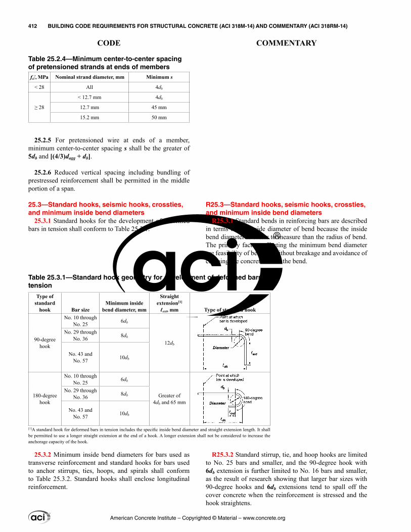
R25.3—Standard hooks, seismic hooks, crossties, and minimum inside bend diameters
R25.3.1 Standard bends in reinforcing bars are described in terms of the inside diameter of bend because the inside bend diameter is easier to measure than the radius of bend. The primary factors affecting the minimum bend diameter are feasibility of bending without breakage and avoidance of crushing the concrete inside the bend.
R25.3.2 Standard stirrup, tie, and hoop hooks are limited to No. 25 bars and smaller, and the 90-degree hook with 6db extension is further limited to No. 16 bars and smaller, as the result of research showing that larger bar sizes with 90-degree hooks and 6db extensions tend to spall off the cover concrete when the reinforcement is stressed and the hook straightens.
Table 25.2.4—Minimum center-to-center spacing of pretensioned strands at ends of membersfci′, MPa Nominal strand diameter, mm Minimum s
< 28 All 4db
≥ 28
< 12.7 mm 4db
12.7 mm 45 mm
15.2 mm 50 mm
25.2.5 For pretensioned wire at ends of a member, minimum center-to-center spacing s shall be the greater of 5db and [(4/3)dagg + db].
25.2.6 Reduced vertical spacing including bundling of prestressed reinforcement shall be permitted in the middle portion of a span.
25.3—Standard hooks, seismic hooks, crossties, and minimum inside bend diameters
25.3.1 Standard hooks for the development of deformed bars in tension shall conform to Table 25.3.1.
25.3.2 Minimum inside bend diameters for bars used as transverse reinforcement and standard hooks for bars used to anchor stirrups, ties, hoops, and spirals shall conform to Table 25.3.2. Standard hooks shall enclose longitudinal reinforcement.
Table 25.3.1—Standard hook geometry for development of deformed bars in tension
Type of standard
hook Bar sizeMinimum inside
bend diameter, mm
Straight extension[1]
ℓext, mm Type of standard hook
90-degree hook
No. 10 through No. 25 6db
12db
No. 29 through No. 36 8db
No. 43 and No. 57 10db
180-degree hook
No. 10 through No. 25 6db
Greater of4db and 65 mm
No. 29 through No. 36 8db
No. 43 and No. 57 10db
[1]A standard hook for deformed bars in tension includes the specific inside bend diameter and straight extension length. It shall be permitted to use a longer straight extension at the end of a hook. A longer extension shall not be considered to increase the anchorage capacity of the hook.
American Concrete Institute – Copyrighted © Material – www.concrete.org
412 BUILDING CODE REQUIREMENTS FOR STRUCTURAL CONCRETE (ACI 318M-14) AND COMMENTARY (ACI 318RM-14)
CODE COMMENTARY
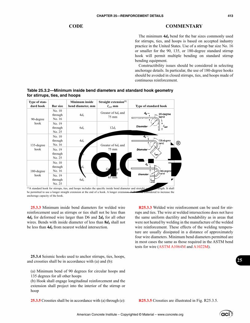
The minimum 4db bend for the bar sizes commonly used for stirrups, ties, and hoops is based on accepted industry practice in the United States. Use of a stirrup bar size No. 16 or smaller for the 90, 135, or 180-degree standard stirrup hook will permit multiple bending on standard stirrup bending equipment.
Constructibility issues should be considered in selecting anchorage details. In particular, the use of 180-degree hooks should be avoided in closed stirrups, ties, and hoops made of continuous reinforcement.
R25.3.3 Welded wire reinforcement can be used for stir-rups and ties. The wire at welded intersections does not have the same uniform ductility and bendability as in areas that were not heated by welding in the manufacture of the welded wire reinforcement. These effects of the welding tempera-ture are usually dissipated in a distance of approximately four wire diameters. Minimum bend diameters permitted are in most cases the same as those required in the ASTM bend tests for wire (ASTM A1064M and A1022M).
R25.3.5 Crossties are illustrated in Fig. R25.3.5.
25.3.3 Minimum inside bend diameters for welded wire reinforcement used as stirrups or ties shall not be less than 4db for deformed wire larger than D6 and 2db for all other wires. Bends with inside diameter of less than 8db shall not be less than 4db from nearest welded intersection.
25.3.4 Seismic hooks used to anchor stirrups, ties, hoops, and crossties shall be in accordance with (a) and (b):
(a) Minimum bend of 90 degrees for circular hoops and 135 degrees for all other hoops(b) Hook shall engage longitudinal reinforcement and the extension shall project into the interior of the stirrup or hoop
25.3.5 Crossties shall be in accordance with (a) through (e):
Table 25.3.2—Minimum inside bend diameters and standard hook geometry for stirrups, ties, and hoops
Type of stan-dard hook Bar size
Minimum inside bend diameter, mm
Straight extension[1]
ℓext, mm Type of standard hook
90-degree hook
No. 10 through No. 16
4dbGreater of 6db and
75 mm
No. 19 through No. 25
6db 12db
135-degree hook
No. 10 through No. 16
4db
Greater of 6db and 75 mmNo. 19
through No. 25
6db
180-degree hook
No. 10 through No. 16
4db Greater of4db and65 mmNo. 19
through No. 25
6db
[1]A standard hook for stirrups, ties, and hoops includes the specific inside bend diameter and straight extension length. It shall be permitted to use a longer straight extension at the end of a hook. A longer extension shall not be considered to increase the anchorage capacity of the hook.
American Concrete Institute – Copyrighted © Material – www.concrete.org
CHAPTER 25—REINFORCEMENT DETAILS 413
CODE COMMENTARY
25
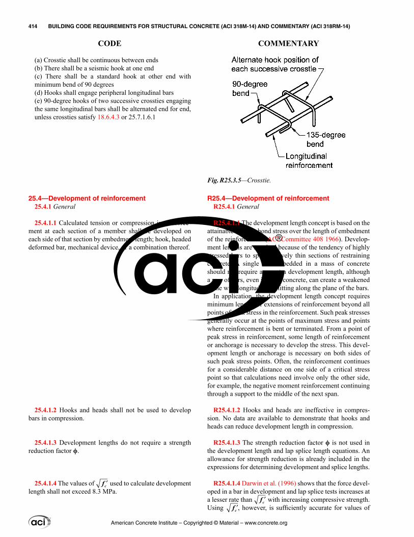
R25.4—Development of reinforcement R25.4.1 General
R25.4.1.1 The development length concept is based on the attainable average bond stress over the length of embedment of the reinforcement (ACI Committee 408 1966). Develop-ment lengths are required because of the tendency of highly stressed bars to split relatively thin sections of restraining concrete. A single bar embedded in a mass of concrete should not require as great a development length, although a row of bars, even in mass concrete, can create a weakened plane with longitudinal splitting along the plane of the bars.
In application, the development length concept requires minimum lengths or extensions of reinforcement beyond all points of peak stress in the reinforcement. Such peak stresses generally occur at the points of maximum stress and points where reinforcement is bent or terminated. From a point of peak stress in reinforcement, some length of reinforcement or anchorage is necessary to develop the stress. This devel-opment length or anchorage is necessary on both sides of such peak stress points. Often, the reinforcement continues for a considerable distance on one side of a critical stress point so that calculations need involve only the other side, for example, the negative moment reinforcement continuing through a support to the middle of the next span.
R25.4.1.2 Hooks and heads are ineffective in compres-sion. No data are available to demonstrate that hooks and heads can reduce development length in compression.
R25.4.1.3 The strength reduction factor ϕ is not used in the development length and lap splice length equations. An allowance for strength reduction is already included in the expressions for determining development and splice lengths.
R25.4.1.4 Darwin et al. (1996) shows that the force devel-oped in a bar in development and lap splice tests increases at a lesser rate than ′fc with increasing compressive strength. Using ′fc , however, is sufficiently accurate for values of
(a) Crosstie shall be continuous between ends(b) There shall be a seismic hook at one end(c) There shall be a standard hook at other end with minimum bend of 90 degrees(d) Hooks shall engage peripheral longitudinal bars(e) 90-degree hooks of two successive crossties engaging the same longitudinal bars shall be alternated end for end, unless crossties satisfy 18.6.4.3 or 25.7.1.6.1
25.4—Development of reinforcement 25.4.1 General
25.4.1.1 Calculated tension or compression in reinforce-ment at each section of a member shall be developed on each side of that section by embedment length; hook, headed deformed bar, mechanical device, or a combination thereof.
25.4.1.2 Hooks and heads shall not be used to develop bars in compression.
25.4.1.3 Development lengths do not require a strength reduction factor ϕ.
25.4.1.4 The values of ′fc used to calculate development length shall not exceed 8.3 MPa.
Fig. R25.3.5—Crosstie.
American Concrete Institute – Copyrighted © Material – www.concrete.org
414 BUILDING CODE REQUIREMENTS FOR STRUCTURAL CONCRETE (ACI 318M-14) AND COMMENTARY (ACI 318RM-14)
CODE COMMENTARY
′fc up to 8.3 MPa, and because of the long-standing use of the ′fc in design, ACI Committee 318 has chosen not to change the exponent applied to the compressive strength used to calculate development and lap splice lengths, but rather to set an upper limit of 8.3 MPa on ′fc .
R25.4.2 Development of deformed bars and deformed wires in tension
R25.4.2.1 This provision gives a two-tier approach for the calculation of tension development length. The user can either use the simplified provisions of 25.4.2.2 or the general development length equation (Eq. (25.4.2.3a)), which is based on the expression previously endorsed by ACI 408.1R (Jirsa et al. 1979). In Table 25.4.2.2, ℓd is based on two prese-lected values of (cb + Ktr)/db, whereas ℓd from Eq. (25.4.2.3a) is based on the actual (cb + Ktr)/db.
Although there is no requirement for transverse rein-forcement along the tension development or lap splice length, research (Azizinamini et al. 1999a,b) indicates that in concrete with very high compressive strength, brittle anchorage failure may occur for bars with inadequate trans-verse reinforcement. In lap splice tests of No. 25 and No. 36 bars in concrete with an fc′ of approximately 105 MPa, transverse reinforcement improved ductile anchorage behavior.
R25.4.2.2 This provision recognizes that many current practical construction cases use spacing and cover values along with confining reinforcement, such as stirrups or ties, that result in a value of (cb + Ktr)/db of at least 1.5. Exam-ples include a minimum clear cover of db along with either minimum clear spacing of 2db, or a combination of minimum clear spacing of db and minimum ties or stirrups. For these frequently occurring cases, the development length for larger bars can be taken as ℓd = [fyψtψe/(1.7λ ′fc )]db. In the formulation of the provisions in ACI 318-95, a comparison with past provisions and a check of a database of experi-mental results maintained by ACI 408.1R indicated that for No. 19 deformed bars and smaller, as well as for deformed wire, the development lengths could be reduced 20 percent using ψs = 0.8. This is the basis for the No. 19 and smaller bars and deformed wires column of Table 25.4.2.2. With less cover and in the absence of minimum ties or stirrups, the minimum clear spacing limits of 25.2.1 and the minimum concrete cover requirements of 20.6.1.3 result in minimum values of cb equal to db. Thus, for “other cases,” the values are based on using (cb + Ktr)/db = 1.0 in Eq. (25.4.2.3a).
The user may easily construct simple, useful expressions. For example, in all members with normalweight concrete (λ = 1.0), uncoated reinforcement (ψe = 1.0), No. 22 and larger bottom bars (ψt = 1.0) with fc′ = 28 MPa, and Grade 420 reinforcement, the expressions reduce to
(420)(1.0)(1.0) 471.7(1.0) 28
= =d b bd dl
25.4.2 Development of deformed bars and deformed wires in tension
25.4.2.1 Development length ℓd for deformed bars and deformed wires in tension shall be the greater of (a) and (b):
(a) Length calculated in accordance with 25.4.2.2 or 25.4.2.3 using the applicable modification factors of 25.4.2.4(b) 300 mm
25.4.2.2 For deformed bars or deformed wires, ℓd shall be calculated in accordance with Table 25.4.2.2.
Table 25.4.2.2—Development length for deformed bars and deformed wires in tension
Spacing and cover
No. 19 and smaller bars and deformed wires
No. 22 and larger bars
Clear spacing of bars or wires being developed or lap spliced not less
than db, clear cover at least db, and stirrups or ties throughout ℓd not less
than the Code minimumor
Clear spacing of bars or wires being developed or lap spliced at least 2db
and clear cover at least db
2.1
ψ ψ λ ′
y t eb
c
fd
f 1.7
ψ ψ
′λ
y t eb
c
fd
f
Other cases1.4
ψ ψ
′λ
y t eb
c
fd
f 1.1
ψ ψ
′λ
y t eb
c
fd
f
American Concrete Institute – Copyrighted © Material – www.concrete.org
CHAPTER 25—REINFORCEMENT DETAILS 415
CODE COMMENTARY
25
25.4.2.3 For deformed bars or deformed wires, ℓd shall be calculated by:
1.1
ψ ψ ψ = +λ ′
y t e sd b
b trc
b
fd
c Kfd
l (25.4.2.3a)
in which the confinement term (cb + Ktr)/db shall not exceed 2.5, and
40 trtr
AK
sn= (25.4.2.3b)
where n is the number of bars or wires being developed or lap spliced along the plane of splitting. It shall be permitted to use Ktr = 0 as a design simplification even if transverse reinforcement is present.
25.4.2.4 For the calculation of ℓd, modification factors shall be in accordance with Table 25.4.2.4.
or
(420)(1.0)(1.0) 721.1(1.0) 28
= =d b bd dl
Thus, as long as minimum cover of db is provided along with a minimum clear spacing of 2db, or a minimum clear cover of db and a minimum clear spacing of db are provided along with minimum ties or stirrups, then ℓd = 47db. The penalty for spacing bars closer or providing less cover is the requirement that ℓd = 72db.
R25.4.2.3 Equation (25.4.2.3a) includes the effects of all variables controlling the development length. In Eq. (25.4.2.3a), cb is a factor that represents the least of the side cover, the concrete cover to the bar or wire (in both cases measured to the center of the bar or wire), or one-half the center-to-center spacing of the bars or wires. Ktr is a factor that represents the contribution of confining reinforcement across potential splitting planes. ψt is the reinforcement location factor to reflect the effect of the casting position (that is, formerly denoted as “top bar effect”). ψe is a coating factor reflecting the effects of epoxy coating. There is a limit on the product ψtψe. The reinforcement size factor ψs reflects the more favorable performance of smaller-diameter reinforcement. A limit of 2.5 is placed on the term (cb + Ktr)/db. When (cb + Ktr)/db is less than 2.5, splitting failures are likely to occur. For values above 2.5, a pullout failure is expected, and an increase in cover or transverse reinforce-ment is unlikely to increase the anchorage capacity.
Many practical combinations of side cover, clear cover, and confining reinforcement can be used with 25.4.2.3 to produce significantly shorter development lengths than allowed by 25.4.2.2. For example, bars or wires with minimum clear cover not less than 2db and minimum clear spacing not less than 4db and without any confining rein-forcement would have a (cb + Ktr)/db value of 2.5 and would require a development length of only 28db for the example in R25.4.2.2.
Before ACI 318-08, Eq. (25.4.2.3b) for Ktr included the yield strength of transverse reinforcement. The current expression includes only the area and spacing of the trans-verse reinforcement and the number of wires or bars being developed or lap spliced because tests demonstrate that transverse reinforcement rarely yields during a bond failure (Azizinamini et al. 1995).
Terms in Eq. (25.4.2.3a) may be disregarded if such omis-sion results in longer and, hence, more conservative, devel-opment lengths.
R25.4.2.4 The lightweight factor λ for calculating devel-opment length of deformed bars and deformed wire in tension is the same for all types of lightweight aggregate concrete. Research does not support the variations of this factor in Codes prior to 1989 for all-lightweight and sand-
American Concrete Institute – Copyrighted © Material – www.concrete.org
416 BUILDING CODE REQUIREMENTS FOR STRUCTURAL CONCRETE (ACI 318M-14) AND COMMENTARY (ACI 318RM-14)
CODE COMMENTARY
Table 25.4.2.4—Modification factors for development of deformed bars and deformed wires in tension
Modification factor Condition
Value of factor
Lightweightλ
Lightweight concrete 0.75
Lightweight concrete, where fct is specified
In accordance with 19.2.4.3
Normalweight concrete 1.0
Epoxy[1]
ψe
Epoxy-coated or zinc and epoxy dual-coated reinforcement with clear cover less than 3db or clear spacing
less than 6db
1.5
Epoxy-coated or zinc and epoxy dual-coated reinforcement for all other
conditions1.2
Uncoated or zinc-coated (galvanized) reinforcement 1.0
Sizeψs
No. 22 and larger bars 1.0
No. 19 and smaller bars and deformed wires 0.8
Casting position[1]
ψt
More than 300 mm of fresh concrete placed below horizontal
reinforcement1.3
Other 1.0[1]The product ψtψe need not exceed 1.7.
25.4.3 Development of standard hooks in tension
25.4.3.1 Development length ℓdh for deformed bars in tension terminating in a standard hook shall be the greater of (a) through (c):
(a) 0.24 ψ ψ ψ λ ′
y e c rb
c
fd
f with ψe, ψc, ψr, and λ given in 25.4.3.2.
(b) 8db(c) 150 mm
lightweight concrete. Section 25.4.2.4 allows a higher factor to be used when the splitting tensile strength of the light-weight concrete is specified. Refer to 19.2.4.
The epoxy factor ψe is based on studies (Treece and Jirsa 1989; Johnston and Zia 1982; Mathey and Clifton 1976) of the anchorage of epoxy-coated bars that show bond strength is reduced because the coating prevents adhesion and lowers the coefficient of friction between the bar and the concrete. The factors reflect the type of anchorage failure likely to occur. If the cover or spacing is small, a splitting failure can occur and the anchorage or bond strength is substan-tially reduced. If the cover and spacing between bars is large, a splitting failure is precluded and the effect of the epoxy coating on anchorage strength is not as large. Studies (Orangun et al. 1977) have shown that although the cover or spacing may be small, the anchorage strength may be increased by adding transverse reinforcement crossing the plane of splitting, and restraining the splitting crack.
Because the bond of epoxy-coated bars or zinc and epoxy dual-coated bars is already reduced due to the loss of adhe-sion and lower coefficient of friction between the bar and the concrete, an upper limit of 1.7 is established for the product of the factors for top reinforcement casting position and epoxy-coated reinforcement or zinc and epoxy dual-coated reinforcement.
The reinforcement size factor ψs reflects the more favor-able performance of smaller-diameter reinforcement.
The reinforcement location or casting position factor ψt accounts for the position of the reinforcement in freshly placed concrete. The factor 1.3 is based on research (Jirsa and Breen 1981; Jeanty et al. 1988). The application of the casting position factor should be considered in determina-tion of development lengths for inclined reinforcement.
R25.4.3 Development of standard hooks in tension
R25.4.3.1 Study of failures of hooked bars indicate that splitting of the concrete cover in the plane of the hook is the primary cause of failure and that splitting originates at the inside of the hook where local stress concentrations are very high. Thus, hook development is a direct function of bar diameter db, which governs the magnitude of compres-sive stresses on the inside of the hook. Only standard hooks (refer to 25.3.1) are considered, and the influence of larger bend radii cannot be evaluated by 25.4.3.
The hooked bar anchorage provisions give the total hooked bar embedment length as shown in Table 25.3.1. The development length ℓdh is measured from the critical section to the outside end (or edge) of the hook.
The effects of bar yield strength, excess reinforcement, lightweight concrete, and factors to reflect the resistance to splitting provided from confinement by concrete and trans-verse ties or stirrups are based on recommendations from ACI 408.1R and Jirsa et al. (1979).
American Concrete Institute – Copyrighted © Material – www.concrete.org
CHAPTER 25—REINFORCEMENT DETAILS 417
CODE COMMENTARY
25
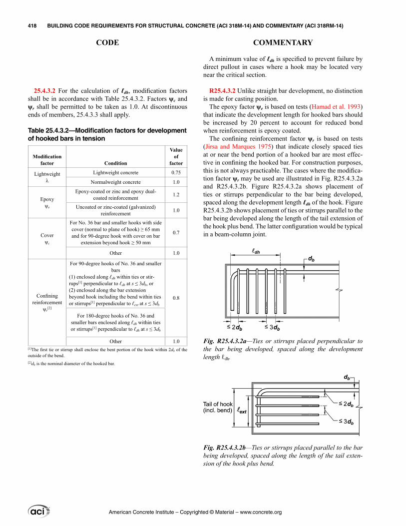
25.4.3.2 For the calculation of ℓdh, modification factors shall be in accordance with Table 25.4.3.2. Factors ψc and ψr shall be permitted to be taken as 1.0. At discontinuous ends of members, 25.4.3.3 shall apply.
Table 25.4.3.2—Modification factors for development of hooked bars in tension
Modification factor Condition
Value of
factor
Lightweightλ
Lightweight concrete 0.75
Normalweight concrete 1.0
Epoxyψe
Epoxy-coated or zinc and epoxy dual-coated reinforcement 1.2
Uncoated or zinc-coated (galvanized) reinforcement 1.0
Coverψc
For No. 36 bar and smaller hooks with side cover (normal to plane of hook) ≥ 65 mm and for 90-degree hook with cover on bar
extension beyond hook ≥ 50 mm
0.7
Other 1.0
Confiningreinforcement
ψr[2]
For 90-degree hooks of No. 36 and smaller bars
(1) enclosed along ℓdh within ties or stir-rups[1] perpendicular to ℓdh at s ≤ 3db, or(2) enclosed along the bar extension beyond hook including the bend within ties or stirrups[1] perpendicular to ℓext at s ≤ 3db
0.8
For 180-degree hooks of No. 36 and smaller bars enclosed along ℓdh within ties or stirrups[1] perpendicular to ℓdh at s ≤ 3db
Other 1.0[1]The first tie or stirrup shall enclose the bent portion of the hook within 2db of the outside of the bend.[2]db is the nominal diameter of the hooked bar.
A minimum value of ℓdh is specified to prevent failure by direct pullout in cases where a hook may be located very near the critical section.
R25.4.3.2 Unlike straight bar development, no distinction is made for casting position.
The epoxy factor ψe is based on tests (Hamad et al. 1993) that indicate the development length for hooked bars should be increased by 20 percent to account for reduced bond when reinforcement is epoxy coated.
The confining reinforcement factor ψr is based on tests (Jirsa and Marques 1975) that indicate closely spaced ties at or near the bend portion of a hooked bar are most effec-tive in confining the hooked bar. For construction purposes, this is not always practicable. The cases where the modifica-tion factor ψr may be used are illustrated in Fig. R25.4.3.2a and R25.4.3.2b. Figure R25.4.3.2a shows placement of ties or stirrups perpendicular to the bar being developed, spaced along the development length ℓdh of the hook. Figure R25.4.3.2b shows placement of ties or stirrups parallel to the bar being developed along the length of the tail extension of the hook plus bend. The latter configuration would be typical in a beam-column joint.
Fig. R25.4.3.2a—Ties or stirrups placed perpendicular to the bar being developed, spaced along the development length ℓdh.
Fig. R25.4.3.2b—Ties or stirrups placed parallel to the bar being developed, spaced along the length of the tail exten-sion of the hook plus bend.
American Concrete Institute – Copyrighted © Material – www.concrete.org
418 BUILDING CODE REQUIREMENTS FOR STRUCTURAL CONCRETE (ACI 318M-14) AND COMMENTARY (ACI 318RM-14)
CODE COMMENTARY
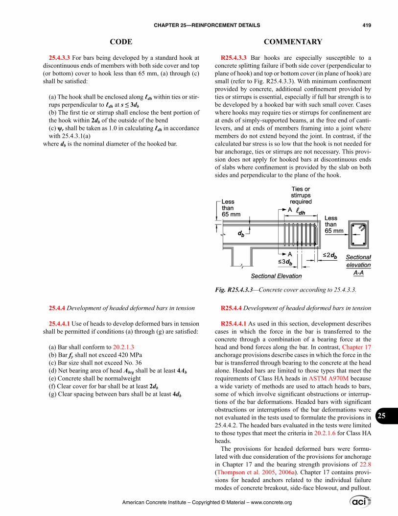
25.4.3.3 For bars being developed by a standard hook at discontinuous ends of members with both side cover and top (or bottom) cover to hook less than 65 mm, (a) through (c) shall be satisfied:
(a) The hook shall be enclosed along ℓdh within ties or stir-rups perpendicular to ℓdh at s ≤ 3db(b) The first tie or stirrup shall enclose the bent portion of the hook within 2db of the outside of the bend(c) ψr shall be taken as 1.0 in calculating ℓdh in accordance with 25.4.3.1(a)
where db is the nominal diameter of the hooked bar.
25.4.4 Development of headed deformed bars in tension
25.4.4.1 Use of heads to develop deformed bars in tension shall be permitted if conditions (a) through (g) are satisfied:
(a) Bar shall conform to 20.2.1.3(b) Bar fy shall not exceed 420 MPa(c) Bar size shall not exceed No. 36(d) Net bearing area of head Abrg shall be at least 4Ab(e) Concrete shall be normalweight(f) Clear cover for bar shall be at least 2db(g) Clear spacing between bars shall be at least 4db
R25.4.3.3 Bar hooks are especially susceptible to a concrete splitting failure if both side cover (perpendicular to plane of hook) and top or bottom cover (in plane of hook) are small (refer to Fig. R25.4.3.3). With minimum confinement provided by concrete, additional confinement provided by ties or stirrups is essential, especially if full bar strength is to be developed by a hooked bar with such small cover. Cases where hooks may require ties or stirrups for confinement are at ends of simply-supported beams, at the free end of canti-levers, and at ends of members framing into a joint where members do not extend beyond the joint. In contrast, if the calculated bar stress is so low that the hook is not needed for bar anchorage, ties or stirrups are not necessary. This provi-sion does not apply for hooked bars at discontinuous ends of slabs where confinement is provided by the slab on both sides and perpendicular to the plane of the hook.
R25.4.4 Development of headed deformed bars in tension
R25.4.4.1 As used in this section, development describes cases in which the force in the bar is transferred to the concrete through a combination of a bearing force at the head and bond forces along the bar. In contrast, Chapter 17 anchorage provisions describe cases in which the force in the bar is transferred through bearing to the concrete at the head alone. Headed bars are limited to those types that meet the requirements of Class HA heads in ASTM A970M because a wide variety of methods are used to attach heads to bars, some of which involve significant obstructions or interrup-tions of the bar deformations. Headed bars with significant obstructions or interruptions of the bar deformations were not evaluated in the tests used to formulate the provisions in 25.4.4.2. The headed bars evaluated in the tests were limited to those types that meet the criteria in 20.2.1.6 for Class HA heads.
The provisions for headed deformed bars were formu-lated with due consideration of the provisions for anchorage in Chapter 17 and the bearing strength provisions of 22.8 (Thompson et al. 2005, 2006a). Chapter 17 contains provi-sions for headed anchors related to the individual failure modes of concrete breakout, side-face blowout, and pullout.
Fig. R25.4.3.3—Concrete cover according to 25.4.3.3.
American Concrete Institute – Copyrighted © Material – www.concrete.org
CHAPTER 25—REINFORCEMENT DETAILS 419
CODE COMMENTARY
25
25.4.4.2 Development length ℓdt for headed deformed bars in tension shall be the greatest of (a) through (c):
(a) 0.19 ψ
′
y eb
c
fd
f, with ψe given in 25.4.4.3 and value of
fc′ shall not exceed 40 MPa(b) 8db(c) 150 mm
These failure modes were considered in the formulation of 25.4.4.2. The restrictions on the upper limit of 420 MPa for fy, maximum bar size of No. 36, and normalweight concrete are based on the available data from tests (Thompson et al. 2005, 2006a,b).
For bars in tension, heads allow the bars to be devel-oped in a shorter length than required for standard hooks (Thompson et al. 2005, 2006a,b). The minimum limits on head size, clear cover, and clear spacing are based on the lower limits of these parameters used in the tests to establish the expression for ℓdt in 25.4.4.2. The clear cover and clear spacing requirements in 25.4.4.1 are based on dimensions measured to the bar, not to the head. The head is consid-ered to be part of the bar for the purposes of satisfying the specified cover requirements in 20.6.1.3, and aggregate size requirements of 26.4.2.1(a)(4). To avoid congestion, it may be desirable to stagger the heads. Headed bars with Abrg < 4Ab have been used in practice, but their performance is not accurately represented by the provisions in 25.4.4.2, and they should be used only with designs that are supported by test results under 25.4.5. These provisions do not address the design of studs or headed stud assemblies used for shear reinforcement.
R25.4.4.2 The provisions for developing headed deformed bars give the length of bar, ℓdt, measured from the critical section to the bearing face of the head, as shown in Fig. R25.4.4.2a.
The upper limit on the value of fc′ in 25.4.4.2 for use in calculating ℓdt is based on the concrete strengths used in the tests (Thompson et al. 2005, 2006a,b). Because trans-verse reinforcement has been shown to be largely ineffec-tive in improving the anchorage of headed deformed bars (Thompson et al. 2005, 2006a,b), additional reductions in development length, such as those allowed for standard hooks with additional confinement provided by transverse reinforcement in 25.4.3.2, are not used for headed deformed reinforcing bars. Transverse reinforcement, however, helps limit splitting cracks in the vicinity of the head and for that reason is recommended.
Where longitudinal headed deformed bars from a beam or a slab terminate at a supporting member, such as the column shown in Fig. R25.4.4.2b, the bars should extend through the joint to the far face of the confined core of the supporting member, allowing for cover and avoidance of interference with column reinforcement, even though the resulting anchorage length exceeds ℓdt. Extending the bar to the far side of the column core helps to transfer compressive forces (as identified in a strut-and-tie model) that are likely to form in such a connection and improves the performance of the joint.
Where closely spaced headed bars are used, the potential for concrete breakout failure exists. For joints as shown in Fig. R25.4.4.2c and R25.4.4.2d, concrete breakout failure can be precluded by providing anchorage length equal to or greater than d/1.5 (Eligehausen 2006b), as shown
American Concrete Institute – Copyrighted © Material – www.concrete.org
420 BUILDING CODE REQUIREMENTS FOR STRUCTURAL CONCRETE (ACI 318M-14) AND COMMENTARY (ACI 318RM-14)
CODE COMMENTARY
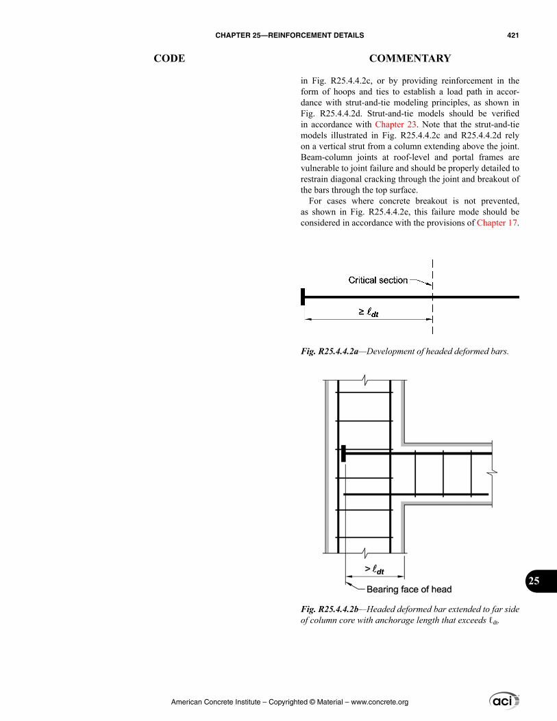
in Fig. R25.4.4.2c, or by providing reinforcement in the form of hoops and ties to establish a load path in accor-dance with strut-and-tie modeling principles, as shown in Fig. R25.4.4.2d. Strut-and-tie models should be verified in accordance with Chapter 23. Note that the strut-and-tie models illustrated in Fig. R25.4.4.2c and R25.4.4.2d rely on a vertical strut from a column extending above the joint. Beam-column joints at roof-level and portal frames are vulnerable to joint failure and should be properly detailed to restrain diagonal cracking through the joint and breakout of the bars through the top surface.
For cases where concrete breakout is not prevented, as shown in Fig. R25.4.4.2e, this failure mode should be considered in accordance with the provisions of Chapter 17.
Fig. R25.4.4.2a—Development of headed deformed bars.
Fig. R25.4.4.2b—Headed deformed bar extended to far side of column core with anchorage length that exceeds ℓdt.
American Concrete Institute – Copyrighted © Material – www.concrete.org
CHAPTER 25—REINFORCEMENT DETAILS 421
CODE COMMENTARY
25
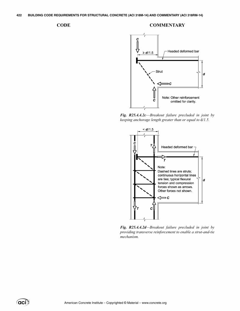
Fig. R25.4.4.2c––Breakout failure precluded in joint by keeping anchorage length greater than or equal to d/1.5.
Fig. R25.4.4.2d—Breakout failure precluded in joint by providing transverse reinforcement to enable a strut-and-tie mechanism.
American Concrete Institute – Copyrighted © Material – www.concrete.org
422 BUILDING CODE REQUIREMENTS FOR STRUCTURAL CONCRETE (ACI 318M-14) AND COMMENTARY (ACI 318RM-14)
CODE COMMENTARY
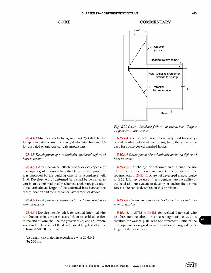
R25.4.4.3 A 1.2 factor is conservatively used for epoxy-coated headed deformed reinforcing bars, the same value used for epoxy-coated standard hooks.
R25.4.5 Development of mechanically anchored deformed bars in tension
R25.4.5.1 Anchorage of deformed bars through the use of mechanical devices within concrete that do not meet the requirements in 20.2.1.6, or are not developed in accordance with 25.4.4, may be used if tests demonstrate the ability of the head and bar system to develop or anchor the desired force in the bar, as described in this provision.
R25.4.6 Development of welded deformed wire reinforce-ment in tension
R25.4.6.1 ASTM A1064M for welded deformed wire reinforcement requires the same strength of the weld as required for welded plain wire reinforcement. Some of the development is assigned to welds and some assigned to the length of deformed wire.
25.4.4.3 Modification factor ψe in 25.4.4.2(a) shall be 1.2 for epoxy-coated or zinc and epoxy dual-coated bars and 1.0 for uncoated or zinc-coated (galvanized) bars.
25.4.5 Development of mechanically anchored deformed bars in tension
25.4.5.1 Any mechanical attachment or device capable of developing fy of deformed bars shall be permitted, provided it is approved by the building official in accordance with 1.10. Development of deformed bars shall be permitted to consist of a combination of mechanical anchorage plus addi-tional embedment length of the deformed bars between the critical section and the mechanical attachment or device.
25.4.6 Development of welded deformed wire reinforce-ment in tension
25.4.6.1 Development length ℓd for welded deformed wire reinforcement in tension measured from the critical section to the end of wire shall be the greater of (a) and (b), where wires in the direction of the development length shall all be deformed MD200 or smaller.
(a) Length calculated in accordance with 25.4.6.2(b) 200 mm
Fig. R25.4.4.2e—Breakout failure not precluded; Chapter 17 provisions applicable.
American Concrete Institute – Copyrighted © Material – www.concrete.org
CHAPTER 25—REINFORCEMENT DETAILS 423
CODE COMMENTARY
25
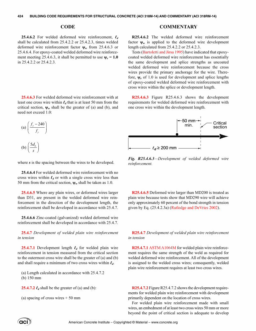
R25.4.6.2 The welded deformed wire reinforcement factor ψw is applied to the deformed wire development length calculated from 25.4.2.2 or 25.4.2.3.
Tests (Bartoletti and Jirsa 1995) have indicated that epoxy-coated welded deformed wire reinforcement has essentially the same development and splice strengths as uncoated welded deformed wire reinforcement because the cross wires provide the primary anchorage for the wire. There-fore, ψe of 1.0 is used for development and splice lengths of epoxy-coated welded deformed wire reinforcement with cross wires within the splice or development length.
R25.4.6.3 Figure R25.4.6.3 shows the development requirements for welded deformed wire reinforcement with one cross wire within the development length.
R25.4.6.5 Deformed wire larger than MD200 is treated as plain wire because tests show that MD290 wire will achieve only approximately 60 percent of the bond strength in tension given by Eq. (25.4.2.3a) (Rutledge and DeVries 2002).
R25.4.7 Development of welded plain wire reinforcement in tension
R25.4.7.1 ASTM A1064M for welded plain wire reinforce-ment requires the same strength of the weld as required for welded deformed wire reinforcement. All of the development is assigned to the welded cross wires; consequently, welded plain wire reinforcement requires at least two cross wires.
R25.4.7.2 Figure R25.4.7.2 shows the development require-ments for welded plain wire reinforcement with development primarily dependent on the location of cross wires.
For welded plain wire reinforcement made with small wires, an embedment of at least two cross wires 50 mm or more beyond the point of critical section is adequate to develop
25.4.6.2 For welded deformed wire reinforcement, ℓd shall be calculated from 25.4.2.2 or 25.4.2.3, times welded deformed wire reinforcement factor ψw from 25.4.6.3 or 25.4.6.4. For epoxy-coated welded deformed wire reinforce-ment meeting 25.4.6.3, it shall be permitted to use ψe = 1.0 in 25.4.2.2 or 25.4.2.3.
25.4.6.3 For welded deformed wire reinforcement with at least one cross wire within ℓd that is at least 50 mm from the critical section, ψw shall be the greater of (a) and (b), and need not exceed 1.0:
(a) 240 −
y
y
ff
(b) 5 bd
s
where s is the spacing between the wires to be developed.
25.4.6.4 For welded deformed wire reinforcement with no cross wires within ℓd or with a single cross wire less than 50 mm from the critical section, ψw shall be taken as 1.0.
25.4.6.5 Where any plain wires, or deformed wires larger than D31, are present in the welded deformed wire rein-forcement in the direction of the development length, the reinforcement shall be developed in accordance with 25.4.7.
25.4.6.6 Zinc-coated (galvanized) welded deformed wire reinforcement shall be developed in accordance with 25.4.7.
25.4.7 Development of welded plain wire reinforcement in tension
25.4.7.1 Development length ℓd for welded plain wire reinforcement in tension measured from the critical section to the outermost cross wire shall be the greater of (a) and (b) and shall require a minimum of two cross wires within ℓd.
(a) Length calculated in accordance with 25.4.7.2(b) 150 mm
25.4.7.2 ℓd shall be the greater of (a) and (b):
(a) spacing of cross wires + 50 mm
Fig. R25.4.6.3—Development of welded deformed wire reinforcement.
American Concrete Institute – Copyrighted © Material – www.concrete.org
424 BUILDING CODE REQUIREMENTS FOR STRUCTURAL CONCRETE (ACI 318M-14) AND COMMENTARY (ACI 318RM-14)
CODE COMMENTARY
the full yield strength of the anchored wires. However, for welded plain wire reinforcement made with larger closely spaced wires, a longer embedment is required with the development length controlled by 25.4.7.2(b).
R25.4.8 Development of pretensioned seven-wire strands in tension—Development requirements for pretensioned strand are intended to provide bond integrity for the strength of the member. Provisions are based on tests performed on normalweight concrete members with a minimum cover of 50 mm. These tests may not represent the behavior of strand in no-slump concrete. Concrete placement operations should ensure consolidation of concrete around the strand with complete contact between the steel and concrete.
The bond of strand is a function of a number of factors, including the configuration and surface condition of the steel, the stress in the steel, the depth of concrete beneath the strand, and the method used to transfer the force in the strand to the concrete. For bonded applications, quality assurance procedures should be used to confirm that the strand is capable of adequate bond (Rose and Russell 1997; Logan 1997). The precast concrete manufacturer may rely on certification from the strand manufacturer that the strand has bond characteristics that comply with this section.
This section does not apply to plain wires, to end-anchored tendons, or to unstressed strand. The develop-ment length for plain wire could be considerably greater due to the absence of mechanical interlock. Flexural bond failure would occur with plain wire when first slip occurred. Unstressed prestressing steel is sometimes used as integrity reinforcement in precast concrete structures; however, there are limited data available regarding the bond length required to ensure development of the yield strength of the reinforce-ment (Salmons and McCrate 1977).
R25.4.8.1 The first term in Eq. (25.4.8.1) represents the transfer length of the strand, that is, the distance over which the strand should be bonded to the concrete to develop the effective prestress in the prestressing steel, fse. The second term represents the additional length over which the strand should be bonded so that the stress in the prestressing steel at nominal strength of the member, fps, may develop.
Exploratory tests (Kaar and Magura 1965) that studied the effect of debonded strand (bond not permitted to extend to the ends of members) on performance of pretensioned
(b) 3.3 λ ′
y b
c
f Asf
, where s is the spacing between the
wires to be developed, and λ is given in Table 25.4.2.4.
25.4.8 Development of pretensioned seven-wire strands in tension
25.4.8.1 Development length ℓd of pretensioned seven-wire strands in tension shall be in accordance with (a) and (b):
(a) 21 7
− = + ps sese
d b b
f ffd dl (25.4.8.1)
(b) If bonding of a strand does not extend to end of member, and design includes tension at service loads
Fig. R25.4.7.2—Development of welded plain wire reinforcement.
American Concrete Institute – Copyrighted © Material – www.concrete.org
CHAPTER 25—REINFORCEMENT DETAILS 425
CODE COMMENTARY
25
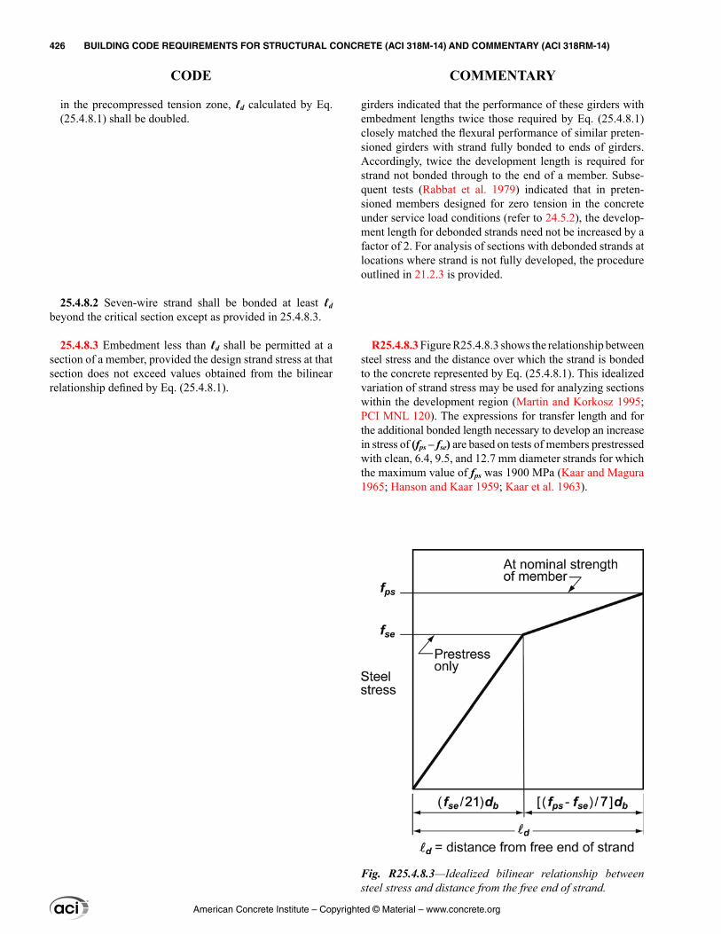
girders indicated that the performance of these girders with embedment lengths twice those required by Eq. (25.4.8.1) closely matched the flexural performance of similar preten-sioned girders with strand fully bonded to ends of girders. Accordingly, twice the development length is required for strand not bonded through to the end of a member. Subse-quent tests (Rabbat et al. 1979) indicated that in preten-sioned members designed for zero tension in the concrete under service load conditions (refer to 24.5.2), the develop-ment length for debonded strands need not be increased by a factor of 2. For analysis of sections with debonded strands at locations where strand is not fully developed, the procedure outlined in 21.2.3 is provided.
R25.4.8.3 Figure R25.4.8.3 shows the relationship between steel stress and the distance over which the strand is bonded to the concrete represented by Eq. (25.4.8.1). This idealized variation of strand stress may be used for analyzing sections within the development region (Martin and Korkosz 1995; PCI MNL 120). The expressions for transfer length and for the additional bonded length necessary to develop an increase in stress of (fps – fse) are based on tests of members prestressed with clean, 6.4, 9.5, and 12.7 mm diameter strands for which the maximum value of fps was 1900 MPa (Kaar and Magura 1965; Hanson and Kaar 1959; Kaar et al. 1963).
in the precompressed tension zone, ℓd calculated by Eq. (25.4.8.1) shall be doubled.
25.4.8.2 Seven-wire strand shall be bonded at least ℓd beyond the critical section except as provided in 25.4.8.3.
25.4.8.3 Embedment less than ℓd shall be permitted at a section of a member, provided the design strand stress at that section does not exceed values obtained from the bilinear relationship defined by Eq. (25.4.8.1).
Fig. R25.4.8.3—Idealized bilinear relationship between steel stress and distance from the free end of strand.
American Concrete Institute – Copyrighted © Material – www.concrete.org
426 BUILDING CODE REQUIREMENTS FOR STRUCTURAL CONCRETE (ACI 318M-14) AND COMMENTARY (ACI 318RM-14)
CODE COMMENTARY
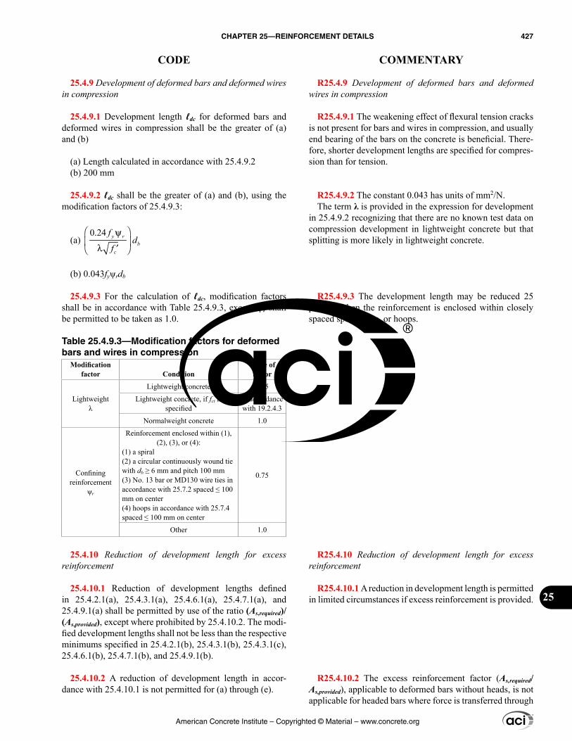
R25.4.9 Development of deformed bars and deformed wires in compression
R25.4.9.1 The weakening effect of flexural tension cracks is not present for bars and wires in compression, and usually end bearing of the bars on the concrete is beneficial. There-fore, shorter development lengths are specified for compres-sion than for tension.
R25.4.9.2 The constant 0.043 has units of mm2/N.The term λ is provided in the expression for development
in 25.4.9.2 recognizing that there are no known test data on compression development in lightweight concrete but that splitting is more likely in lightweight concrete.
R25.4.9.3 The development length may be reduced 25 percent when the reinforcement is enclosed within closely spaced spirals, ties, or hoops.
R25.4.10 Reduction of development length for excess reinforcement
R25.4.10.1 A reduction in development length is permitted in limited circumstances if excess reinforcement is provided.
R25.4.10.2 The excess reinforcement factor (As,required/As,provided), applicable to deformed bars without heads, is not applicable for headed bars where force is transferred through
25.4.9 Development of deformed bars and deformed wires in compression
25.4.9.1 Development length ℓdc for deformed bars and deformed wires in compression shall be the greater of (a) and (b)
(a) Length calculated in accordance with 25.4.9.2(b) 200 mm
25.4.9.2 ℓdc shall be the greater of (a) and (b), using the modification factors of 25.4.9.3:
(a) 0.24 ψ
λ ′ y r
bc
fd
f
(b) 0.043fyψrdb
25.4.9.3 For the calculation of ℓdc, modification factors shall be in accordance with Table 25.4.9.3, except ψr shall be permitted to be taken as 1.0.
Table 25.4.9.3—Modification factors for deformed bars and wires in compression
Modification factor Condition
Value of factor
Lightweightλ
Lightweight concrete 0.75
Lightweight concrete, if fct is specified
In accordance with 19.2.4.3
Normalweight concrete 1.0
Confining reinforcement
ψr
Reinforcement enclosed within (1), (2), (3), or (4):
(1) a spiral(2) a circular continuously wound tie with db ≥ 6 mm and pitch 100 mm(3) No. 13 bar or MD130 wire ties in accordance with 25.7.2 spaced ≤ 100 mm on center(4) hoops in accordance with 25.7.4 spaced ≤ 100 mm on center
0.75
Other 1.0
25.4.10 Reduction of development length for excess reinforcement
25.4.10.1 Reduction of development lengths defined in 25.4.2.1(a), 25.4.3.1(a), 25.4.6.1(a), 25.4.7.1(a), and 25.4.9.1(a) shall be permitted by use of the ratio (As,required)/(As,provided), except where prohibited by 25.4.10.2. The modi-fied development lengths shall not be less than the respective minimums specified in 25.4.2.1(b), 25.4.3.1(b), 25.4.3.1(c), 25.4.6.1(b), 25.4.7.1(b), and 25.4.9.1(b).
25.4.10.2 A reduction of development length in accor-dance with 25.4.10.1 is not permitted for (a) through (e).
American Concrete Institute – Copyrighted © Material – www.concrete.org
CHAPTER 25—REINFORCEMENT DETAILS 427
CODE COMMENTARY
25
a combination of bearing at the head and bond along the bar. Concrete breakout due to bearing at the head was considered in developing the provisions of 25.4.4. Because the concrete breakout strength of a headed bar is a function of the embed-ment depth to the 1.5 power (refer to Eq. (17.4.2.2a)), a reduction in development length with the application of the excess reinforcement factor could result in a potential concrete breakout failure.
Where a flexural member is part of the seismic-force-resisting-system, loads greater than those anticipated in design may cause reversal of moment at supports; some positive reinforcement should be fully developed into the support. This anchorage is required to ensure ductile response in the event of serious overstress, such as from earthquake or blast. It is not sufficient to use more reinforce-ment at lower stresses.
The reduction factor based on area is not to be used in those cases where anchorage development for full fy is required. For example, the excess reinforcement factor does not apply for development of shrinkage and temperature reinforcement according to 24.4.3.4 or for development of reinforcement provided according to 8.7.4.2, 8.8.1.6, 9.7.7, and 9.8.1.6.
R25.5—Splices R25.5.1 Lap splice lengths of longitudinal reinforcement
in columns should be calculated in accordance with 10.7.5, 18.7.4.3, and this section.
R25.5.1.1 Because of lack of adequate experimental data on lap splices of No. 43 and No. 57 bars in compression and in tension, lap splicing of these bar sizes is prohibited except as permitted in 25.5.5.3 for compression lap splices of No. 43 and No. 57 bars with smaller bars.
R25.5.1.3 If individual bars in noncontact lap splices are too widely spaced, an unreinforced section is created. Forcing a potential crack to follow a zigzag line (5-to-1 slope) is considered a minimum precaution. The 150 mm. maximum spacing is added because most research available on the lap splicing of deformed bars was conducted with reinforcement within this spacing.
R25.5.1.4 The development length ℓd used to obtain lap length should be based on fy because the splice classifica-tions already reflect any excess reinforcement at the splice location; therefore, the factor from 25.4.10.1 for excess As should not be used.
(a) At noncontinuous supports(b) At locations where anchorage or development for fy is required(c) Where bars are required to be continuous(d) For headed and mechanically anchored deformed reinforcement(e) In seismic-force-resisting systems in structures assigned to Seismic Design Categories D, E, or F
25.5—Splices 25.5.1 General
25.5.1.1 Lap splices shall not be permitted for bars larger than No. 36, except as provided in 25.5.5.3.
25.5.1.2 For contact lap splices, minimum clear spacing between the contact lap splice and adjacent splices or bars shall be in accordance with the requirements for individual bars in 25.2.1.
25.5.1.3 For noncontact splices in flexural members, the transverse center-to-center spacing of spliced bars shall not exceed the lesser of one-fifth the required lap splice length and 150 mm.
25.5.1.4 Reduction of development length in accordance with 25.4.10.1 is not permitted in calculating lap splice lengths.
25.5.1.5 Lap splices of bundled bars shall be in accor-dance with 25.6.1.7.
American Concrete Institute – Copyrighted © Material – www.concrete.org
428 BUILDING CODE REQUIREMENTS FOR STRUCTURAL CONCRETE (ACI 318M-14) AND COMMENTARY (ACI 318RM-14)
CODE COMMENTARY
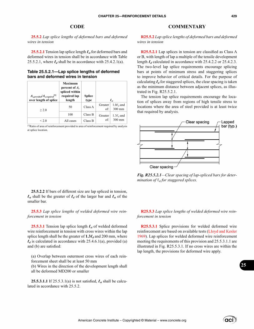
R25.5.2 Lap splice lengths of deformed bars and deformed wires in tension
R25.5.2.1 Lap splices in tension are classified as Class A or B, with length of lap a multiple of the tensile development length ℓd calculated in accordance with 25.4.2.2 or 25.4.2.3. The two-level lap splice requirements encourage splicing bars at points of minimum stress and staggering splices to improve behavior of critical details. For the purpose of calculating ℓd for staggered splices, the clear spacing is taken as the minimum distance between adjacent splices, as illus-trated in Fig. R25.5.2.1.
The tension lap splice requirements encourage the loca-tion of splices away from regions of high tensile stress to locations where the area of steel provided is at least twice that required by analysis.
R25.5.3 Lap splice lengths of welded deformed wire rein-forcement in tension
R25.5.3.1 Splice provisions for welded deformed wire reinforcement are based on available tests (Lloyd and Kesler 1969). Lap splices for welded deformed wire reinforcement meeting the requirements of this provision and 25.5.3.1.1 are illustrated in Fig. R25.5.3.1. If no cross wires are within the lap length, the provisions for deformed wire apply.
25.5.2 Lap splice lengths of deformed bars and deformed wires in tension
25.5.2.1 Tension lap splice length ℓst for deformed bars and deformed wires in tension shall be in accordance with Table 25.5.2.1, where ℓd shall be in accordance with 25.4.2.1(a).
Table 25.5.2.1—Lap splice lengths of deformed bars and deformed wires in tension
As,provided/As,required[1]
over length of splice
Maximum percent of As spliced within required lap
lengthSplice type ℓst
≥ 2.050 Class A Greater
of:1.0ℓd and 300 mm
100 Class B Greater of:
1.3ℓd and 300 mm< 2.0 All cases Class B
[1]Ratio of area of reinforcement provided to area of reinforcement required by analysis at splice location.
25.5.2.2 If bars of different size are lap spliced in tension, ℓst shall be the greater of ℓd of the larger bar and ℓst of the smaller bar.
25.5.3 Lap splice lengths of welded deformed wire rein-forcement in tension
25.5.3.1 Tension lap splice length ℓst of welded deformed wire reinforcement in tension with cross wires within the lap splice length shall be the greater of 1.3ℓd and 200 mm, where ℓd is calculated in accordance with 25.4.6.1(a), provided (a) and (b) are satisfied:
(a) Overlap between outermost cross wires of each rein-forcement sheet shall be at least 50 mm(b) Wires in the direction of the development length shall all be deformed MD200 or smaller
25.5.3.1.1 If 25.5.3.1(a) is not satisfied, ℓst shall be calcu-lated in accordance with 25.5.2.
Fig. R25.5.2.1—Clear spacing of lap-spliced bars for deter-mination of ℓd for staggered splices.
American Concrete Institute – Copyrighted © Material – www.concrete.org
CHAPTER 25—REINFORCEMENT DETAILS 429
CODE COMMENTARY
25
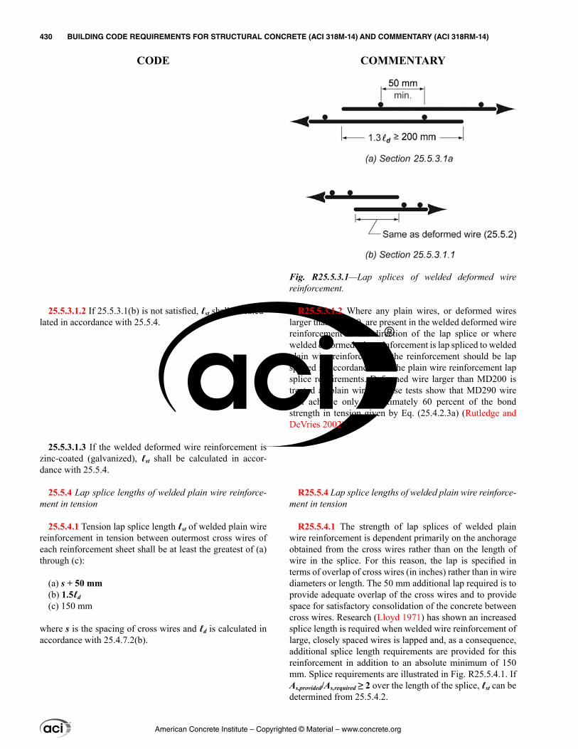
R25.5.3.1.2 Where any plain wires, or deformed wires larger than MD200, are present in the welded deformed wire reinforcement in the direction of the lap splice or where welded deformed wire reinforcement is lap spliced to welded plain wire reinforcement, the reinforcement should be lap spliced in accordance with the plain wire reinforcement lap splice requirements. Deformed wire larger than MD200 is treated as plain wire because tests show that MD290 wire will achieve only approximately 60 percent of the bond strength in tension given by Eq. (25.4.2.3a) (Rutledge and DeVries 2002).
R25.5.4 Lap splice lengths of welded plain wire reinforce-ment in tension
R25.5.4.1 The strength of lap splices of welded plain wire reinforcement is dependent primarily on the anchorage obtained from the cross wires rather than on the length of wire in the splice. For this reason, the lap is specified in terms of overlap of cross wires (in inches) rather than in wire diameters or length. The 50 mm additional lap required is to provide adequate overlap of the cross wires and to provide space for satisfactory consolidation of the concrete between cross wires. Research (Lloyd 1971) has shown an increased splice length is required when welded wire reinforcement of large, closely spaced wires is lapped and, as a consequence, additional splice length requirements are provided for this reinforcement in addition to an absolute minimum of 150 mm. Splice requirements are illustrated in Fig. R25.5.4.1. If As,provided/As,required ≥ 2 over the length of the splice, ℓst can be determined from 25.5.4.2.
25.5.3.1.2 If 25.5.3.1(b) is not satisfied, ℓst shall be calcu-lated in accordance with 25.5.4.
25.5.3.1.3 If the welded deformed wire reinforcement is zinc-coated (galvanized), ℓst shall be calculated in accor-dance with 25.5.4.
25.5.4 Lap splice lengths of welded plain wire reinforce-ment in tension
25.5.4.1 Tension lap splice length ℓst of welded plain wire reinforcement in tension between outermost cross wires of each reinforcement sheet shall be at least the greatest of (a) through (c):
(a) s + 50 mm(b) 1.5ℓd(c) 150 mm
where s is the spacing of cross wires and ℓd is calculated in accordance with 25.4.7.2(b).
Fig. R25.5.3.1—Lap splices of welded deformed wire reinforcement.
American Concrete Institute – Copyrighted © Material – www.concrete.org
430 BUILDING CODE REQUIREMENTS FOR STRUCTURAL CONCRETE (ACI 318M-14) AND COMMENTARY (ACI 318RM-14)
CODE COMMENTARY
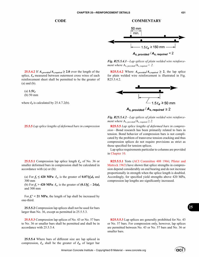
R25.5.4.2 Where As,provided/As,required ≥ 2, the lap splice for plain welded wire reinforcement is illustrated in Fig. R25.5.4.2.
R25.5.5 Lap splice lengths of deformed bars in compres-sion—Bond research has been primarily related to bars in tension. Bond behavior of compression bars is not compli-cated by the problem of transverse tension cracking and thus compression splices do not require provisions as strict as those specified for tension splices.
Lap splice requirements particular to columns are provided in Chapter 10.
R25.5.5.1 Tests (ACI Committee 408 1966; Pfister and Mattock 1963) have shown that splice strengths in compres-sion depend considerably on end bearing and do not increase proportionally in strength when the splice length is doubled. Accordingly, for specified yield strengths above 420 MPa, compression lap lengths are significantly increased.
R25.5.5.3 Lap splices are generally prohibited for No. 43 or No. 57 bars. For compression only, however, lap splices are permitted between No. 43 or No. 57 bars and No. 36 or smaller bars.
25.5.4.2 If As,provided/As,required ≥ 2.0 over the length of the splice, ℓst measured between outermost cross wires of each reinforcement sheet shall be permitted to be the greater of (a) and (b).
(a) 1.5ℓd(b) 50 mm
where ℓd is calculated by 25.4.7.2(b).
25.5.5 Lap splice lengths of deformed bars in compression
25.5.5.1 Compression lap splice length ℓsc of No. 36 or smaller deformed bars in compression shall be calculated in accordance with (a) or (b):
(a) For fy ≤ 420 MPa: ℓsc is the greater of 0.071fydb and 300 mm(b) For fy > 420 MPa: ℓsc is the greater of (0.13fy – 24)db and 300 mm
For fc′ < 21 MPa, the length of lap shall be increased by one-third.
25.5.5.2 Compression lap splices shall not be used for bars larger than No. 36, except as permitted in 25.5.5.3.
25.5.5.3 Compression lap splices of No. 43 or No. 57 bars to No. 36 or smaller bars shall be permitted and shall be in accordance with 25.5.5.4.
25.5.5.4 Where bars of different size are lap spliced in compression, ℓsc shall be the greater of ℓdc of larger bar
Fig. R25.5.4.1—Lap splices of plain welded wire reinforce-ment where As, provided/As, required < 2.
Fig. R25.5.4.2—Lap splices of plain welded wire reinforce-ment where As, provided/As, required ≥ 2.
American Concrete Institute – Copyrighted © Material – www.concrete.org
CHAPTER 25—REINFORCEMENT DETAILS 431
CODE COMMENTARY
25
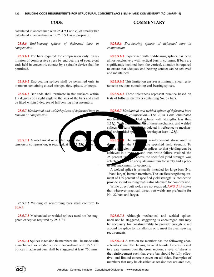
R25.5.6 End-bearing splices of deformed bars in compression
R25.5.6.1 Experience with end-bearing splices has been almost exclusively with vertical bars in columns. If bars are significantly inclined from the vertical, attention is required to ensure that adequate end-bearing contact can be achieved and maintained.
R25.5.6.2 This limitation ensures a minimum shear resis-tance in sections containing end-bearing splices.
R25.5.6.3 These tolerances represent practice based on tests of full-size members containing No. 57 bars.
R25.5.7 Mechanical and welded splices of deformed bars in tension or compression—The 2014 Code eliminated mechanical and welded splices with strengths less than 1.25fy. With the elimination of these mechanical and welded splices, the term “full” was deleted in reference to mechan-ical and welded splices that develop at least 1.25fy.
R25.5.7.1 The maximum reinforcement stress used in design under the Code is the specified yield strength. To ensure sufficient strength in splices so that yielding can be achieved in a member and thus brittle failure avoided, the 25 percent increase above the specified yield strength was selected as both an adequate minimum for safety and a prac-ticable maximum for economy.
A welded splice is primarily intended for large bars (No. 19 and larger) in main members. The tensile strength require-ment of 125 percent of specified yield strength is intended to provide sound welding that is also adequate for compression.
While direct butt welds are not required, AWS D1.4 states that wherever practical, direct butt welds are preferable for No. 22 bars and larger.
R25.5.7.3 Although mechanical and welded splices need not be staggered, staggering is encouraged and may be necessary for constructibility to provide enough space around the splice for installation or to meet the clear spacing requirements.
R25.5.7.4 A tension tie member has the following char-acteristics: member having an axial tensile force sufficient to create tension over the cross section; a level of stress in the reinforcement such that every bar should be fully effec-tive; and limited concrete cover on all sides. Examples of members that may be classified as tension ties are arch ties,
calculated in accordance with 25.4.9.1 and ℓsc of smaller bar calculated in accordance with 25.5.5.1 as appropriate.
25.5.6 End-bearing splices of deformed bars in compression
25.5.6.1 For bars required for compression only, trans-mission of compressive stress by end bearing of square-cut ends held in concentric contact by a suitable device shall be permitted.
25.5.6.2 End-bearing splices shall be permitted only in members containing closed stirrups, ties, spirals, or hoops.
25.5.6.3 Bar ends shall terminate in flat surfaces within 1.5 degrees of a right angle to the axis of the bars and shall be fitted within 3 degrees of full bearing after assembly.
25.5.7 Mechanical and welded splices of deformed bars in tension or compression
25.5.7.1 A mechanical or welded splice shall develop in tension or compression, as required, at least 1.25fy of the bar.
25.5.7.2 Welding of reinforcing bars shall conform to 26.6.4.
25.5.7.3 Mechanical or welded splices need not be stag-gered except as required by 25.5.7.4.
25.5.7.4 Splices in tension tie members shall be made with a mechanical or welded splice in accordance with 25.5.7.1. Splices in adjacent bars shall be staggered at least 750 mm.
American Concrete Institute – Copyrighted © Material – www.concrete.org
432 BUILDING CODE REQUIREMENTS FOR STRUCTURAL CONCRETE (ACI 318M-14) AND COMMENTARY (ACI 318RM-14)
CODE COMMENTARY
hangers carrying load to an overhead supporting structure, and main tension elements in a truss.
In determining if a member should be classified as a tension tie, consideration should be given to the importance, function, proportions, and stress conditions of the member related to the above characteristics. For example, a usual large circular tank, with many bars and with splices well staggered and widely spaced, should not be classified as a tension tie member, and Class B splices may be used.
R25.6—Bundled reinforcement R25.6.1 Nonprestressed reinforcement
R25.6.1.1 The Code phrase “bundled in contact to act as a unit” is intended to preclude bundling more than two bars in the same plane. Typical bundle shapes in cross section are triangular, L-shaped, or square-shaped patterns for three- or four-bar bundles. As a practical caution, bundles more than one bar deep in the plane of bending should not be hooked or bent as a unit. Where end hooks are required, it is preferable to stagger the individual bar hooks within a bundle.
R25.6.1.3 A limitation that bars larger than No. 36 not be bundled in beams is a practical limit for application to building size members. (AASHTO LRFDUS permits two-bar bundles for No. 43 and No. 57 bars in bridge girders.) Conformance to the crack control requirements of 24.3 will effectively preclude bundling of bars larger than No. 36 as tension reinforcement.
R25.6.1.4 Bond research (ACI Committee 408 1966) has shown that bar cutoffs within bundles should be staggered.
R25.6.1.5 An increased development length for individual bars is required when three or four bars are bundled together. The extra extension is needed because the grouping makes it more difficult to mobilize bond resistance from the core between the bars.
The development of bundled bars by a standard hook of the bundle is not covered by the provisions of 25.4.3.
R25.6.1.6 Although splice and development lengths of bundled bars are a multiple of the diameter of the individual bars being spliced increased by 20 or 33 percent, as appro-priate, it is necessary to use an equivalent diameter of the entire bundle derived from the equivalent total area of bars for determining the spacing and cover values in 25.4.2.2, the confinement term, [(cb + Ktr)/db], in 25.4.2.3, and the ψe factor in 25.4.2.4. For bundled bars, bar diameter db
25.6—Bundled reinforcement 25.6.1 Nonprestressed reinforcement
25.6.1.1 Groups of parallel reinforcing bars bundled in contact to act as a unit shall be limited to four in any one bundle.
25.6.1.2 Bundled bars shall be enclosed within transverse reinforcement. Bundled bars in compression members shall be enclosed by transverse reinforcement at least No. 13 in size.
25.6.1.3 Bars larger than a No. 36 shall not be bundled in beams.
25.6.1.4 Individual bars within a bundle terminated within the span of flexural members shall terminate at different points with at least 40db stagger.
25.6.1.5 Development length for individual bars within a bundle, in tension or compression, shall be that of the indi-vidual bar, increased 20 percent for a three-bar bundle, and 33 percent for a four-bar bundle.
25.6.1.6 A unit of bundled bars shall be treated as a single bar with an area equivalent to that of the bundle and a centroid coinciding with that of the bundle. The diameter of the equivalent bar shall be used for db in (a) through (e):
(a) Spacing limitations based on db(b) Cover requirements based on db(c) Spacing and cover values in 25.4.2.2(d) Confinement term in 25.4.2.3
American Concrete Institute – Copyrighted © Material – www.concrete.org
CHAPTER 25—REINFORCEMENT DETAILS 433
CODE COMMENTARY
25
outside the brackets in the expressions of 25.4.2.2 and of Eq. (25.4.2.3a) is that of a single bar.
R25.6.1.7 The increased length of lap required for bars in bundles is based on the reduction in the exposed perimeter of the bars. Only individual bars are lap spliced along the bundle.
R25.6.2 Post-tensioning ducts
R25.6.2.1 Where ducts for prestressing steel in a beam are arranged closely together vertically, provisions should be made to prevent the prestressing steel from breaking through the duct when tensioned. Horizontal arrangement of ducts should allow proper placement of concrete. A clear spacing of one and one-third times the nominal maximum size of the coarse aggregate, but not less than 25 mm, has proven satisfactory.
Where concentration of tendons or ducts tends to create a weakened plane in the concrete cover, reinforcement should be provided to control cracking.
R25.7—Transverse reinforcement R25.7.1 Stirrups
R25.7.1.1 Stirrup legs should be extended as close as prac-ticable to the compression face of the member because, near ultimate load, the flexural tension cracks penetrate deeply toward the compression zone.
It is essential that shear and torsional reinforcement be adequately anchored at both ends to be fully effective on either side of any potential inclined crack. This generally requires a hook or bend at the end of the reinforcement as provided by this section.
R25.7.1.3 Straight deformed bar and wire anchorage is not permitted because it is difficult to hold such a stirrup in position during concrete placement. Moreover, the lack of a standard stirrup hook may make the stirrup ineffective as it crosses shear cracks near the end of the stirrup.
For a No. 16 or MD200 or smaller stirrup, anchorage is provided by a standard hook, as defined in 25.3.2, hooked around a longitudinal bar.
For a No. 19, No. 22, or No. 25 stirrup with fyt of only 280 MPa, a standard stirrup hook around a longitudinal bar provides sufficient anchorage. For a No. 19, No. 22, or No. 25 stirrup with higher strength, the embedment should be checked. A 135-degree or 180-degree hook is preferred, but a 90-degree hook may be used provided the free end of the 90-degree hook is extended the full 12 bar diameters as required in 25.3.2. Because it is not possible to bend a No. 19, No. 22,
(e) ψe factor in 25.4.2.4
25.6.1.7 Lap splices of bars in a bundle shall be based on the lap splice length required for individual bars within the bundle, increased in accordance with 25.6.1.5. Individual bar splices within a bundle shall not overlap. Entire bundles shall not be lap spliced.
25.6.2 Post-tensioning ducts
25.6.2.1 Bundling of post-tensioning ducts shall be permitted if shown that concrete can be satisfactorily placed and if provision is made to prevent the prestressing steel, when tensioned, from breaking through the duct.
25.7—Transverse reinforcement 25.7.1 Stirrups
25.7.1.1 Stirrups shall extend as close to the compression and tension surfaces of the member as cover requirements and proximity of other reinforcement permits and shall be anchored at both ends. Where used as shear reinforcement, stirrups shall extend a distance d from extreme compression fiber.
25.7.1.2 Between anchored ends, each bend in the contin-uous portion of a single or multiple U-stirrup and each bend in a closed stirrup shall enclose a longitudinal bar or strand.
25.7.1.3 Anchorage of deformed bar and wire shall be in accordance with (a), (b), or (c):
(a) For No. 16 bar and MD200 wire, and smaller, and for No. 19 through No. 25 bars with fyt ≤ 280 MPa, a standard hook around longitudinal reinforcement(b) For No. 19 through No. 25 bars with fyt > 280 MPa, a standard hook around a longitudinal bar plus an embed-ment between midheight of the member and the outside end of the hook equal to or greater than 0.17dbfyt/(λ ′fc ), with λ as given in Table 25.4.3.2(c) In joist construction, for No. 13 bar and MD130 wire and smaller, a standard hook
American Concrete Institute – Copyrighted © Material – www.concrete.org
434 BUILDING CODE REQUIREMENTS FOR STRUCTURAL CONCRETE (ACI 318M-14) AND COMMENTARY (ACI 318RM-14)
CODE COMMENTARY
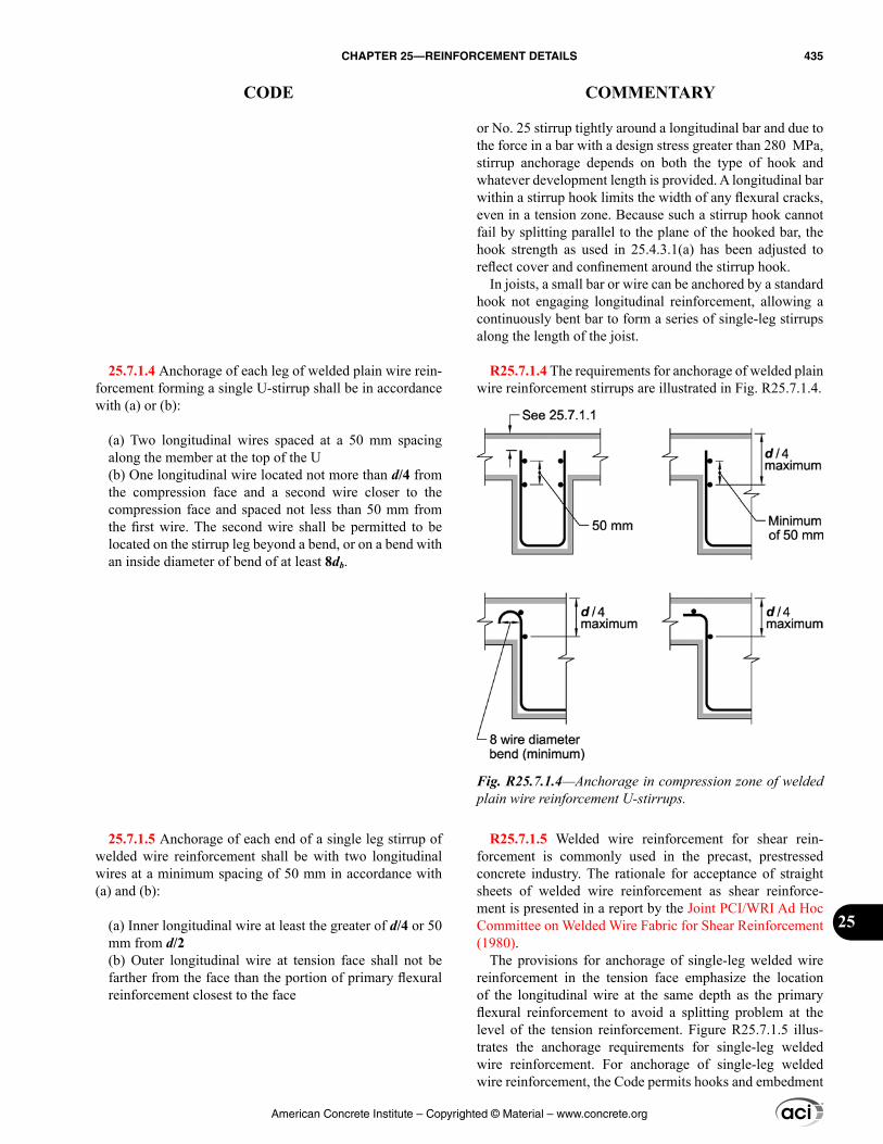
25.7.1.4 Anchorage of each leg of welded plain wire rein-forcement forming a single U-stirrup shall be in accordance with (a) or (b):
(a) Two longitudinal wires spaced at a 50 mm spacing along the member at the top of the U(b) One longitudinal wire located not more than d/4 from the compression face and a second wire closer to the compression face and spaced not less than 50 mm from the first wire. The second wire shall be permitted to be located on the stirrup leg beyond a bend, or on a bend with an inside diameter of bend of at least 8db.
25.7.1.5 Anchorage of each end of a single leg stirrup of welded wire reinforcement shall be with two longitudinal wires at a minimum spacing of 50 mm in accordance with (a) and (b):
(a) Inner longitudinal wire at least the greater of d/4 or 50 mm from d/2(b) Outer longitudinal wire at tension face shall not be farther from the face than the portion of primary flexural reinforcement closest to the face
or No. 25 stirrup tightly around a longitudinal bar and due to the force in a bar with a design stress greater than 280 MPa, stirrup anchorage depends on both the type of hook and whatever development length is provided. A longitudinal bar within a stirrup hook limits the width of any flexural cracks, even in a tension zone. Because such a stirrup hook cannot fail by splitting parallel to the plane of the hooked bar, the hook strength as used in 25.4.3.1(a) has been adjusted to reflect cover and confinement around the stirrup hook.
In joists, a small bar or wire can be anchored by a standard hook not engaging longitudinal reinforcement, allowing a continuously bent bar to form a series of single-leg stirrups along the length of the joist.
R25.7.1.4 The requirements for anchorage of welded plain wire reinforcement stirrups are illustrated in Fig. R25.7.1.4.
R25.7.1.5 Welded wire reinforcement for shear rein-forcement is commonly used in the precast, prestressed concrete industry. The rationale for acceptance of straight sheets of welded wire reinforcement as shear reinforce-ment is presented in a report by the Joint PCI/WRI Ad Hoc Committee on Welded Wire Fabric for Shear Reinforcement (1980).
The provisions for anchorage of single-leg welded wire reinforcement in the tension face emphasize the location of the longitudinal wire at the same depth as the primary flexural reinforcement to avoid a splitting problem at the level of the tension reinforcement. Figure R25.7.1.5 illus-trates the anchorage requirements for single-leg welded wire reinforcement. For anchorage of single-leg welded wire reinforcement, the Code permits hooks and embedment
Fig. R25.7.1.4—Anchorage in compression zone of welded plain wire reinforcement U-stirrups.
American Concrete Institute – Copyrighted © Material – www.concrete.org
CHAPTER 25—REINFORCEMENT DETAILS 435
CODE COMMENTARY
25
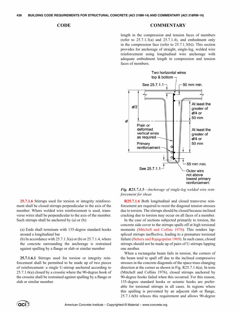
25.7.1.6 Stirrups used for torsion or integrity reinforce-ment shall be closed stirrups perpendicular to the axis of the member. Where welded wire reinforcement is used, trans-verse wires shall be perpendicular to the axis of the member. Such stirrups shall be anchored by (a) or (b):
(a) Ends shall terminate with 135-degree standard hooks around a longitudinal bar(b) In accordance with 25.7.1.3(a) or (b) or 25.7.1.4, where the concrete surrounding the anchorage is restrained against spalling by a flange or slab or similar member
25.7.1.6.1 Stirrups used for torsion or integrity rein-forcement shall be permitted to be made up of two pieces of reinforcement: a single U-stirrup anchored according to 25.7.1.6(a) closed by a crosstie where the 90-degree hook of the crosstie shall be restrained against spalling by a flange or slab or similar member.
length in the compression and tension faces of members (refer to 25.7.1.3(a) and 25.7.1.4), and embedment only in the compression face (refer to 25.7.1.3(b)). This section provides for anchorage of straight, single-leg, welded wire reinforcement using longitudinal wire anchorage with adequate embedment length in compression and tension faces of members.
R25.7.1.6 Both longitudinal and closed transverse rein-forcement are required to resist the diagonal tension stresses due to torsion. The stirrups should be closed because inclined cracking due to torsion may occur on all faces of a member.
In the case of sections subjected primarily to torsion, the concrete side cover to the stirrups spalls off at high torsional moments (Mitchell and Collins 1976). This renders lap-spliced stirrups ineffective, leading to a premature torsional failure (Behera and Rajagopalan 1969). In such cases, closed stirrups should not be made up of pairs of U-stirrups lapping one another.
When a rectangular beam fails in torsion, the corners of the beam tend to spall off due to the inclined compressive stresses in the concrete diagonals of the space truss changing direction at the corner as shown in Fig. R25.7.1.6(a). In tests (Mitchell and Collins 1976), closed stirrups anchored by 90-degree hooks failed when this occurred. For this reason, 135-degree standard hooks or seismic hooks are prefer-able for torsional stirrups in all cases. In regions where this spalling is prevented by an adjacent slab or flange, 25.7.1.6(b) relaxes this requirement and allows 90-degree
Fig. R25.7.1.5—Anchorage of single-leg welded wire rein-forcement for shear.
American Concrete Institute – Copyrighted © Material – www.concrete.org
436 BUILDING CODE REQUIREMENTS FOR STRUCTURAL CONCRETE (ACI 318M-14) AND COMMENTARY (ACI 318RM-14)
CODE COMMENTARY
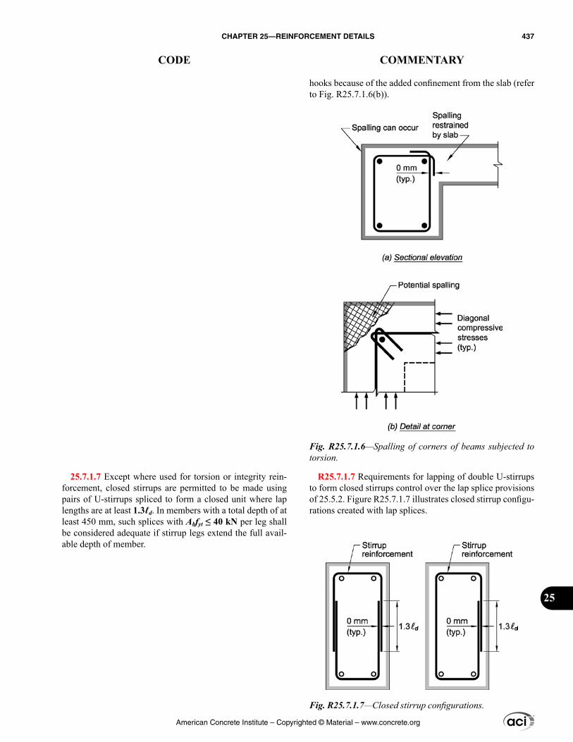
25.7.1.7 Except where used for torsion or integrity rein-forcement, closed stirrups are permitted to be made using pairs of U-stirrups spliced to form a closed unit where lap lengths are at least 1.3ℓd. In members with a total depth of at least 450 mm, such splices with Abfyt ≤ 40 kN per leg shall be considered adequate if stirrup legs extend the full avail-able depth of member.
hooks because of the added confinement from the slab (refer to Fig. R25.7.1.6(b)).
R25.7.1.7 Requirements for lapping of double U-stirrups to form closed stirrups control over the lap splice provisions of 25.5.2. Figure R25.7.1.7 illustrates closed stirrup configu-rations created with lap splices.
Fig. R25.7.1.6—Spalling of corners of beams subjected to torsion.
Fig. R25.7.1.7—Closed stirrup configurations.
American Concrete Institute – Copyrighted © Material – www.concrete.org
CHAPTER 25—REINFORCEMENT DETAILS 437
CODE COMMENTARY
25
25.7.2 Ties
25.7.2.1 Ties shall consist of a closed loop of deformed bar with spacing in accordance with (a) and (b):
(a) Clear spacing of at least (4/3)dagg(b) Center-to-center spacing shall not exceed the least of 16db of longitudinal bar, 48db of tie bar, and smallest dimension of member
25.7.2.2 Diameter of tie bar shall be at least (a) or (b):
(a) No. 10 enclosing No. 32 or smaller longitudinal bars(b) No. 13 enclosing No. 36 or larger longitudinal bars or bundled longitudinal bars
25.7.2.2.1 As an alternative to deformed bars, deformed wire or welded wire reinforcement of equivalent area to that required in 25.7.2.1 shall be permitted subject to the require-ments of Table 20.2.2.4a.
25.7.2.3 Rectilinear ties shall be arranged to satisfy (a) and (b):
(a) Every corner and alternate longitudinal bar shall have lateral support provided by the corner of a tie with an included angle of not more than 135 degrees(b) No unsupported bar shall be farther than 150 mm clear on each side along the tie from a laterally supported bar
R25.7.2 Ties
R25.7.2.2 These provisions apply to crossties as well as ties.
R25.7.2.3 The maximum permissible included angle of 135 degrees and the exemption of bars located within 150 mm clear on each side along the tie from adequately tied bars are illustrated in Fig. R25.7.2.3a. Limited tests (Pfister 1964) on full-size, axially-loaded, tied columns containing full-length bars (without splices) showed that ties on alternate longitu-dinal bars within 150 mm clear of a laterally supported longi-tudinal bar are adequate in columns subjected to axial force.
Continuously wound bars or wires can be considered as ties, provided their pitch and area are at least equivalent to the area and spacing of separate ties. Anchorage at the end of a continuously wound bar or wire should be by a standard hook as for separate bars or by one additional turn of the tie pattern (refer to Fig. R25.7.2.3b). A circular, continuously wound bar or wire is considered a spiral if it conforms to 25.7.3; otherwise, it is considered a tie.
American Concrete Institute – Copyrighted © Material – www.concrete.org
438 BUILDING CODE REQUIREMENTS FOR STRUCTURAL CONCRETE (ACI 318M-14) AND COMMENTARY (ACI 318RM-14)
CODE COMMENTARY
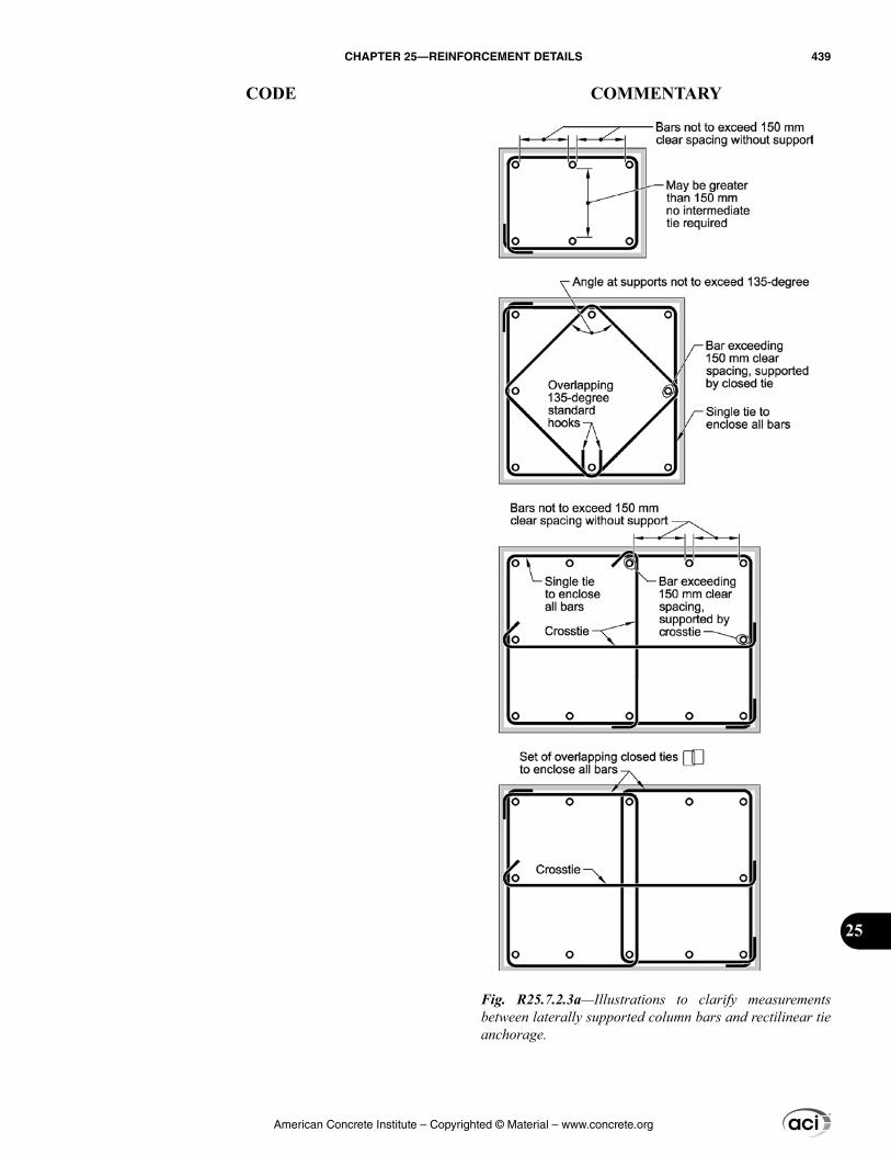
Fig. R25.7.2.3a—Illustrations to clarify measurements between laterally supported column bars and rectilinear tie anchorage.
American Concrete Institute – Copyrighted © Material – www.concrete.org
CHAPTER 25—REINFORCEMENT DETAILS 439
CODE COMMENTARY
25
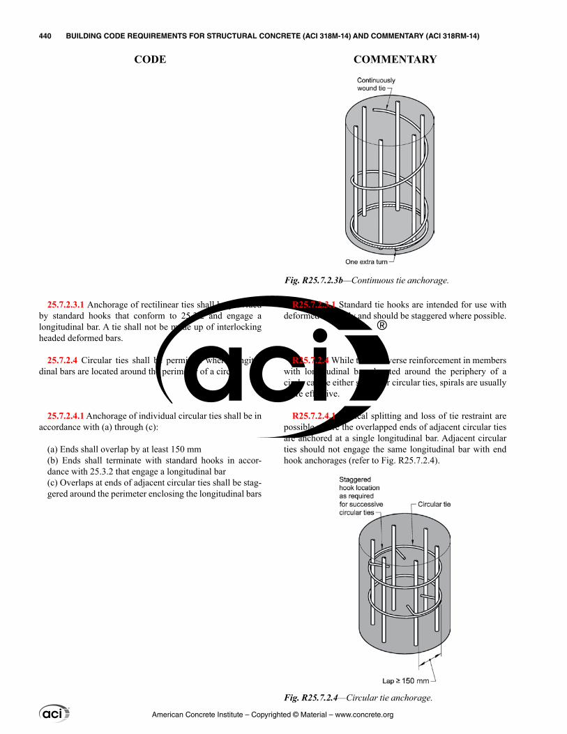
25.7.2.3.1 Anchorage of rectilinear ties shall be provided by standard hooks that conform to 25.3.2 and engage a longitudinal bar. A tie shall not be made up of interlocking headed deformed bars.
25.7.2.4 Circular ties shall be permitted where longitu-dinal bars are located around the perimeter of a circle.
25.7.2.4.1 Anchorage of individual circular ties shall be in accordance with (a) through (c):
(a) Ends shall overlap by at least 150 mm(b) Ends shall terminate with standard hooks in accor-dance with 25.3.2 that engage a longitudinal bar(c) Overlaps at ends of adjacent circular ties shall be stag-gered around the perimeter enclosing the longitudinal bars
R25.7.2.3.1 Standard tie hooks are intended for use with deformed bars only and should be staggered where possible.
R25.7.2.4 While the transverse reinforcement in members with longitudinal bars located around the periphery of a circle can be either spirals or circular ties, spirals are usually more effective.
R25.7.2.4.1 Vertical splitting and loss of tie restraint are possible where the overlapped ends of adjacent circular ties are anchored at a single longitudinal bar. Adjacent circular ties should not engage the same longitudinal bar with end hook anchorages (refer to Fig. R25.7.2.4).
Fig. R25.7.2.3b—Continuous tie anchorage.
Fig. R25.7.2.4—Circular tie anchorage.
American Concrete Institute – Copyrighted © Material – www.concrete.org
440 BUILDING CODE REQUIREMENTS FOR STRUCTURAL CONCRETE (ACI 318M-14) AND COMMENTARY (ACI 318RM-14)
CODE COMMENTARY
25.7.2.5 Ties to resist torsion shall be perpendicular to the axis of the member anchored by either (a) or (b):
(a) Ends shall terminate with 135-degree standard hooks or seismic hooks around a longitudinal bar(b) In accordance with 25.7.1.3(a) or (b) or 25.7.1.4, where the concrete surrounding the anchorage is restrained against spalling
25.7.3 Spirals
25.7.3.1 Spirals shall consist of evenly spaced continuous bar or wire with clear spacing conforming to (a) and (b):
(a) At least the greater of 25 mm and (4/3)dagg(b) Not greater than 75 mm
25.7.3.2 For cast-in-place construction, spiral bar or wire diameter shall be at least 9.5 mm.
25.7.3.3 Volumetric spiral reinforcement ratio ρs shall satisfy Eq. (25.7.3.3).
0.45 1g cs
ch yt
A fA f
′ρ ≥ −
(25.7.3.3)
where the value of fyt shall not be taken greater than 700 MPa.
25.7.3.4 Spirals shall be anchored by 1-1/2 extra turns of spiral bar or wire at each end.
R25.7.2.5 Refer to R25.7.1.6.
R25.7.3 Spirals
R25.7.3.1 Spirals should be held firmly in place, at proper pitch and alignment, to prevent displacement during concrete placement.
R25.7.3.2 For practical considerations in cast-in-place construction, the minimum diameter of spiral reinforcement is 9.5 mm (No. 10 deformed or plain bar, or MD70 deformed or MW70 plain wire).
Standard spiral sizes are 9.5, 12.7, and 15.9 mm diameter for hot-rolled or cold-drawn material, plain or deformed.
R25.7.3.3 The effect of spiral reinforcement in increasing the strength of the concrete within the core is not fully real-ized until the column has been subjected to a load and defor-mation sufficient to cause the concrete shell outside the core to spall off. The amount of spiral reinforcement required by Eq. (25.7.3.3) is intended to provide additional strength for concentrically loaded columns equal to or slightly greater than the strength lost when the shell spalls off. The deriva-tion of Eq. (25.7.3.3) is given by Richart (1933). Tests and experience show that columns containing the amount of spiral reinforcement required by this section exhibit consid-erable toughness and ductility. Research (Richart et al. 1929; Richart 1933; Pessiki et al. 2001; Saatcioglu and Razvi 2002) has also indicated that up to 700 MPa yield strength reinforcement can be effectively used for confinement.
R25.7.3.4 Spiral anchorage is illustrated in Fig. R25.7.3.4.
American Concrete Institute – Copyrighted © Material – www.concrete.org
CHAPTER 25—REINFORCEMENT DETAILS 441
CODE COMMENTARY
25
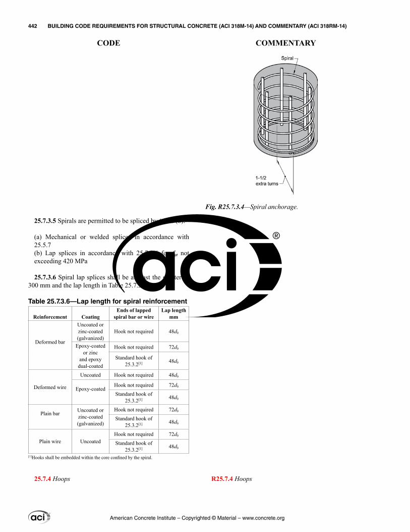
R25.7.4 Hoops
25.7.3.5 Spirals are permitted to be spliced by (a) or (b):
(a) Mechanical or welded splices in accordance with 25.5.7(b) Lap splices in accordance with 25.7.3.6 for fyt not exceeding 420 MPa
25.7.3.6 Spiral lap splices shall be at least the greater of 300 mm and the lap length in Table 25.7.3.6.
Table 25.7.3.6—Lap length for spiral reinforcement
Reinforcement CoatingEnds of lapped
spiral bar or wireLap length
mm
Deformed bar
Uncoated or zinc-coated (galvanized)
Hook not required 48db
Epoxy-coatedor zinc
and epoxy dual-coated
Hook not required 72db
Standard hook of 25.3.2[1] 48db
Deformed wire
Uncoated Hook not required 48db
Epoxy-coatedHook not required 72db
Standard hook of 25.3.2[1] 48db
Plain bar Uncoated or zinc-coated (galvanized)
Hook not required 72db
Standard hook of 25.3.2[1] 48db
Plain wire UncoatedHook not required 72db
Standard hook of 25.3.2[1] 48db
[1]Hooks shall be embedded within the core confined by the spiral.
25.7.4 Hoops
Fig. R25.7.3.4—Spiral anchorage.
American Concrete Institute – Copyrighted © Material – www.concrete.org
442 BUILDING CODE REQUIREMENTS FOR STRUCTURAL CONCRETE (ACI 318M-14) AND COMMENTARY (ACI 318RM-14)
CODE COMMENTARY
R25.7.4.1 Refer to R25.7.2.4.
R25.8—Post-tensioning anchorages and couplers R25.8.1 The required strength of the tendon-anchorage or
tendon-coupler assemblies for both unbonded and bonded tendons, when tested in an unbonded state, is based on 95 percent of the specified tensile strength of the prestressing steel in the test. The prestressing steel is required to comply with the minimum provisions of the applicable ASTM standards as prescribed in 20.3.1. The specified strength of anchorages and couplers exceeds the maximum design strength of the prestressing steel by a substantial margin and, at the same time, recognizes the stress-riser effects associated with most available post-tensioning anchorages and couplers. Anchorage and coupler strength should be attained with a minimum amount of permanent deformation and successive set, recognizing that some deformation and set will occur when testing to failure. Tendon assemblies should conform to the 2 percent elongation requirements in ACI 423.7.
Static and fatigue test methods for anchorage and couplers are provided in ICC-ES Acceptance Criteria AC303 (2011).
R25.8.2 Anchorages and couplers for bonded tendons that develop less than 100 percent of the specified tensile strength of the prestressing steel should be used only where the bond transfer length between the anchorage or coupler and crit-ical sections equals or exceeds that required to develop the prestressing steel strength. This bond length may be calcu-lated based on the results of tests of bond characteristics of untensioned prestressing strand (Salmons and McCrate 1977), or bond tests on other prestressing steel materials, as appropriate.
R25.8.3 A discussion on fatigue loading is provided in ACI 215R.
Detailed recommendations on tests for static and cyclic loading conditions for tendons and anchorage fittings of unbonded tendons are provided in ACI 423.3R (Section 4.1.3) and ACI 301 (Section 15.2.2).
R25.9—Anchorage zones for post-tensioned tendons
R25.9.1 General—The detailed provisions in the AASHTO LRFD Bridge Design Specifications (AASHTO LRFDUS) for analysis and reinforcement detailing of post-
25.7.4.1 Hoops shall consist of a closed tie or continu-ously wound tie, which can consist of several reinforcement elements each having seismic hooks at both ends.
25.7.4.2 The ends of the reinforcement elements in hoops shall be anchored using seismic hooks that conform to 25.3.4 and engage a longitudinal bar. A hoop shall not be made up of interlocking headed deformed bars.
25.8—Post-tensioning anchorages and couplers 25.8.1 Anchorages and couplers for tendons shall develop
at least 95 percent of fpu when tested in an unbonded condi-tion, without exceeding anticipated set.
25.8.2 Anchorages and couplers for bonded tendons shall be located so that 100 percent of fpu shall be developed at critical sections after the post-tensioned reinforcement is bonded in the member.
25.8.3 In unbonded construction subject to repetitive loads, the possibility of fatigue of prestressed reinforcement in anchorages and couplers shall be considered.
25.8.4 Couplers shall be placed at locations approved by the licensed design professional and enclosed in housings long enough to permit necessary movements.
25.9—Anchorage zones for post-tensioned tendons
25.9.1 General
American Concrete Institute – Copyrighted © Material – www.concrete.org
CHAPTER 25—REINFORCEMENT DETAILS 443
CODE COMMENTARY
25
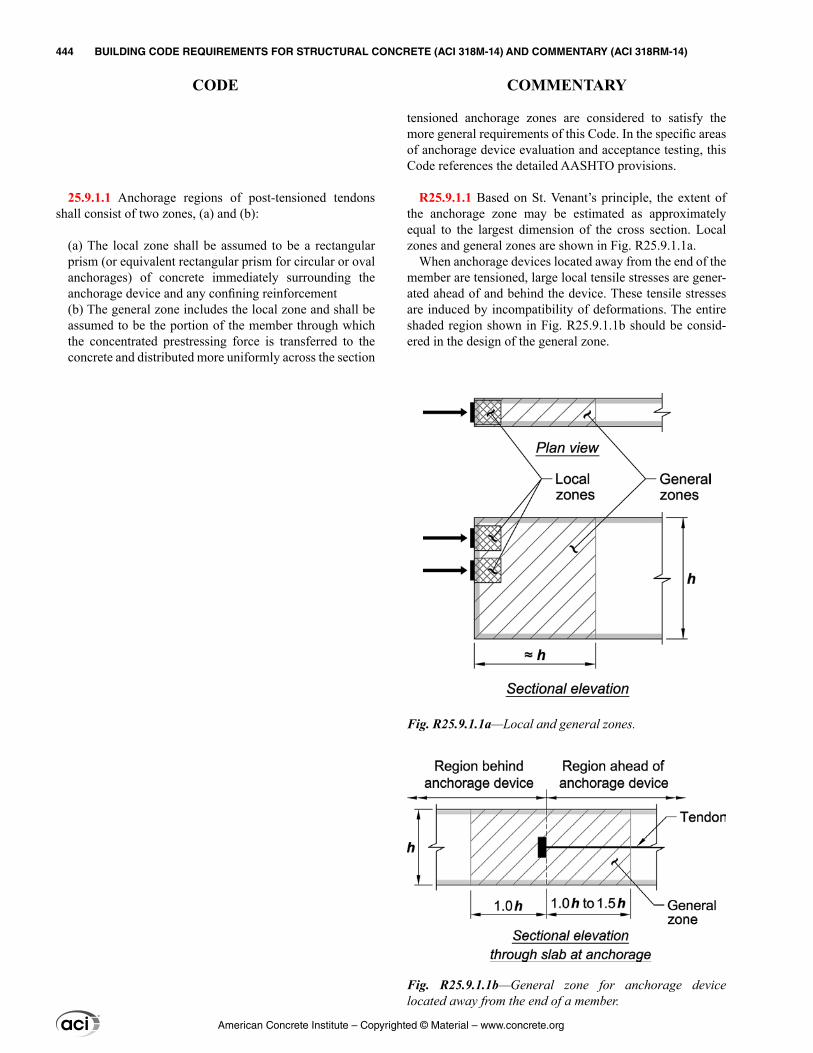
tensioned anchorage zones are considered to satisfy the more general requirements of this Code. In the specific areas of anchorage device evaluation and acceptance testing, this Code references the detailed AASHTO provisions.
R25.9.1.1 Based on St. Venant’s principle, the extent of the anchorage zone may be estimated as approximately equal to the largest dimension of the cross section. Local zones and general zones are shown in Fig. R25.9.1.1a.
When anchorage devices located away from the end of the member are tensioned, large local tensile stresses are gener-ated ahead of and behind the device. These tensile stresses are induced by incompatibility of deformations. The entire shaded region shown in Fig. R25.9.1.1b should be consid-ered in the design of the general zone.
25.9.1.1 Anchorage regions of post-tensioned tendons shall consist of two zones, (a) and (b):
(a) The local zone shall be assumed to be a rectangular prism (or equivalent rectangular prism for circular or oval anchorages) of concrete immediately surrounding the anchorage device and any confining reinforcement(b) The general zone includes the local zone and shall be assumed to be the portion of the member through which the concentrated prestressing force is transferred to the concrete and distributed more uniformly across the section
Fig. R25.9.1.1a—Local and general zones.
Fig. R25.9.1.1b—General zone for anchorage device located away from the end of a member.
American Concrete Institute – Copyrighted © Material – www.concrete.org
444 BUILDING CODE REQUIREMENTS FOR STRUCTURAL CONCRETE (ACI 318M-14) AND COMMENTARY (ACI 318RM-14)
CODE COMMENTARY
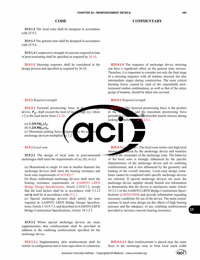
R25.9.1.5 The sequence of anchorage device stressing can have a significant effect on the general zone stresses. Therefore, it is important to consider not only the final stage of a stressing sequence with all tendons stressed, but also intermediate stages during construction. The most critical bursting forces caused by each of the sequentially post-tensioned tendon combinations, as well as that of the entire group of tendons, should be taken into account.
R25.9.2 Required strength
R25.9.2.1 The factored prestressing force is the product of the load factor and the maximum prestressing force permitted. The maximum permissible tensile stresses during jacking are defined in 20.3.2.5.1.
R25.9.3 Local zone—The local zone resists very high local stresses introduced by the anchorage device and transfers them to the remainder of the anchorage zone. The behavior of the local zone is strongly influenced by the specific characteristics of the anchorage device and its confining reinforcement, and is less influenced by the geometry and loading of the overall structure. Local-zone design some-times cannot be completed until specific anchorage devices are selected. If special anchorage devices are used, the anchorage device supplier should furnish test information to demonstrate that the device is satisfactory under Article 10.3.2.3 of the AASHTO LRFD Bridge Construction Speci-fications (LRFDCONS) and provide information regarding necessary conditions for use of the device. The main consid-erations in local-zone design are the effects of high bearing pressure and the adequacy of any confining reinforcement provided to increase concrete bearing resistance.
R25.9.3.2.1 Skin reinforcement is placed near the outer faces in the anchorage zone to limit local crack width
25.9.1.2 The local zone shall be designed in accordance with 25.9.3.
25.9.1.3 The general zone shall be designed in accordance with 25.9.4.
25.9.1.4 Compressive strength of concrete required at time of post-tensioning shall be specified as required by 26.10.
25.9.1.5 Stressing sequence shall be considered in the design process and specified as required by 26.10.
25.9.2 Required strength
25.9.2.1 Factored prestressing force at the anchorage device, Ppu, shall exceed the least of (a) through (c), where 1.2 is the load factor from 5.3.12:
(a) 1.2(0.94fpy)Aps(b) 1.2(0.80fpu)Aps(c) Maximum jacking force designated by the supplier of anchorage devices multiplied by 1.2
25.9.3 Local zone
25.9.3.1 The design of local zone in post-tensioned anchorages shall meet the requirements of (a), (b), or (c):
(a) Monostrand or single 16 mm or smaller diameter bar anchorage devices shall meet the bearing resistance and local zone requirements of ACI 423.7(b) Basic multistrand anchorage devices shall meet the bearing resistance requirements of AASHTO LRFD Bridge Design Specifications, Article 5.10.9.7.2, except that the load factors shall be in accordance with 5.3.12 and ϕ shall be in accordance with 21.2.1(c) Special anchorage devices shall satisfy the tests required in AASHTO LRFD Bridge Design Specifica-tions, Article 5.10.9.7.3, and described in AASHTO LRFD Bridge Construction Specifications, Article 10.3.2.3
25.9.3.2 Where special anchorage devices are used, supplementary skin reinforcement shall be provided in addition to the confining reinforcement specified for the anchorage device.
25.9.3.2.1 Supplementary skin reinforcement shall be similar in configuration and at least equivalent in volumetric
American Concrete Institute – Copyrighted © Material – www.concrete.org
CHAPTER 25—REINFORCEMENT DETAILS 445
CODE COMMENTARY
25
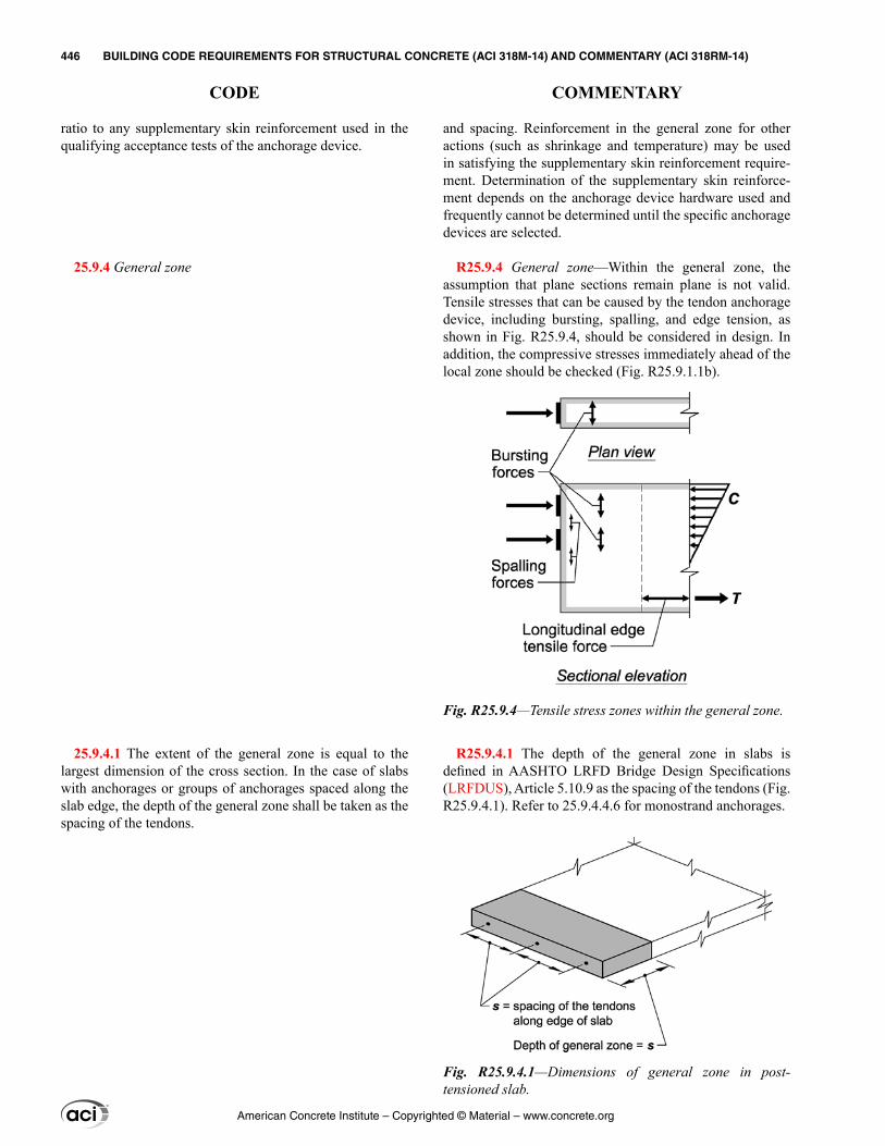
and spacing. Reinforcement in the general zone for other actions (such as shrinkage and temperature) may be used in satisfying the supplementary skin reinforcement require-ment. Determination of the supplementary skin reinforce-ment depends on the anchorage device hardware used and frequently cannot be determined until the specific anchorage devices are selected.
R25.9.4 General zone—Within the general zone, the assumption that plane sections remain plane is not valid. Tensile stresses that can be caused by the tendon anchorage device, including bursting, spalling, and edge tension, as shown in Fig. R25.9.4, should be considered in design. In addition, the compressive stresses immediately ahead of the local zone should be checked (Fig. R25.9.1.1b).
R25.9.4.1 The depth of the general zone in slabs is defined in AASHTO LRFD Bridge Design Specifications (LRFDUS), Article 5.10.9 as the spacing of the tendons (Fig. R25.9.4.1). Refer to 25.9.4.4.6 for monostrand anchorages.
ratio to any supplementary skin reinforcement used in the qualifying acceptance tests of the anchorage device.
25.9.4 General zone
25.9.4.1 The extent of the general zone is equal to the largest dimension of the cross section. In the case of slabs with anchorages or groups of anchorages spaced along the slab edge, the depth of the general zone shall be taken as the spacing of the tendons.
Fig. R25.9.4—Tensile stress zones within the general zone.
Fig. R25.9.4.1—Dimensions of general zone in post-tensioned slab.
American Concrete Institute – Copyrighted © Material – www.concrete.org
446 BUILDING CODE REQUIREMENTS FOR STRUCTURAL CONCRETE (ACI 318M-14) AND COMMENTARY (ACI 318RM-14)
CODE COMMENTARY
R25.9.4.2 The dimensions of the general zone for anchorage devices located away from the end of the member are defined in Fig. R25.9.1.1b.
R25.9.4.3 Analysis of general zones
R25.9.4.3.1 The design methods include those procedures for which guidelines have been given in AASHTO LRFDUS and Breen et al. (1994). These procedures have been shown to be conservative predictors of strength compared to test results (Breen et al. 1994). The use of the strut-and-tie method is especially helpful for general zone design (Breen et al. 1994). In many anchorage applications, where substantial or massive concrete regions surround the anchorages, simplified equa-tions based on AASHTO LRFDUS and Breen et al. (1994) can be used except in the cases noted in 25.9.4.3.2.
Values for the magnitude of the bursting force, Tburst, and for its centroidal distance from the major bearing surface of the anchorage, dburst, may be estimated from Eq. (R25.9.4.3.1a) and (R25.9.4.3.1b), respectively. The terms used in these equations are shown in Fig. R25.9.4.3.1 for a prestressing force with a small eccentricity. In the appli-cation of these equations, the specified stressing sequence should be considered if more than one tendon is present.
0.25 1 ancburst pu
hT P
h = −∑
(R25.9.4.3.1a)
dburst = 0.5(h – 2eanc) (R25.9.4.3.1b)
where ∑Ppu is the sum of the Ppu forces from the individual tendons; hanc is the depth of the anchorage device or single group of closely spaced devices in the direction considered; and eanc is the eccentricity (always taken as positive) of the anchorage device or group of closely spaced devices with respect to the centroid of the cross section (Fig. R25.9.4.3.1).
Anchorage devices should be treated as closely spaced if their center-to-center spacing does not exceed 1.5 times the width of the anchorage device in the direction considered.
25.9.4.2 For anchorage devices located away from the end of a member, the general zone shall include the disturbed regions ahead of and behind the anchorage devices.
25.9.4.3 Analysis of general zones
25.9.4.3.1 Methods (a) through (c) shall be permitted for design of general zones:
(a) Strut-and-tie models in accordance with Chapter 23(b) Linear stress analysis, including finite element analysis or equivalent(c) Simplified equations in AASHTO LRFD Bridge Design Specifications, Article 5.10.9.6, except where restricted by 25.9.4.3.2
The design of general zones by other methods shall be permitted, provided that the specific procedures used for design result in prediction of strength in substantial agree-ment with results of comprehensive tests.
Fig. R25.9.4.3.1—Definition of terms used to define the general zone.
American Concrete Institute – Copyrighted © Material – www.concrete.org
CHAPTER 25—REINFORCEMENT DETAILS 447
CODE COMMENTARY
25
R25.9.4.3.2 The simplified equations in the AASHTO LRFDUS are not applicable in several common situations listed in 25.9.4.3.2. In these cases, a detailed analysis is required. In addition, in the post-tensioning of thin sections, flanged sections, or irregular sections, or where the tendons have appreciable curvature within the general zone, more general procedures such as those of AASHTO LRFDUS Articles 5.10.9.4 and 5.10.9.5 are required. Detailed recom-mendations for design principles that apply to all design methods are given in Article 5.10.9.3.2 of the AASHTO LRFDUS.
Groups of monostrand tendons with individual monostrand anchorage devices are often used in beams. If a beam has a single anchorage device or a single group of closely spaced anchorage devices, the use of simplified equations such as those given in R25.9.4.3.1 is permitted, unless 25.9.4.3.2 governs. More complex conditions can be designed using the strut-and-tie method. Detailed recommendations for use of such models are given in AASHTO LRFDUS and Breen et al. (1994).
R25.9.4.3.3 The provision for three-dimensional effects is to ensure that the effects perpendicular to the main plane of the member, such as bursting forces in the thin direction of webs or slabs are considered. In many cases, these effects can be determined independently for each direction, but some applications require a full three-dimensional analysis (for example, diaphragms for the anchorage of external tendons).
R25.9.4.4 Reinforcement limits
R25.9.4.4.2 In some cases, reinforcement requirements cannot be determined until specific tendon and anchorage device layouts are selected. Design and approval respon-sibilities should be clearly assigned in the construction documents.
Abrupt changes in section can cause substantial deviation in force paths. These deviations can greatly increase tensile forces, as shown in Fig. R25.9.4.4.2.
25.9.4.3.2 Simplified equations as permitted by 25.9.4.3.1(c) shall not be used for the design of a general zone if any of the situations listed in (a) through (g) occur:
(a) Member cross sections are nonrectangular(b) Discontinuities in or near the general zone cause devi-ations in the force flow path(c) Minimum edge distance is less than 1.5 times the anchorage device lateral dimension in that direction(d) Multiple anchorage devices are used in other than one closely spaced group(e) Centroid of the tendons is located outside the kern(f) Angle of inclination of the tendon in the general zone is less than –5 degrees from the centerline of axis of the member, where the angle is negative if the anchor force points away from the centroid of the section(g) Angle of inclination of the tendon in the general zone is greater than +20 degrees from the centerline of axis of the member, where the angle is positive if the anchor force points towards the centroid of the section
25.9.4.3.3 Three-dimensional effects shall be considered in design and analyzed by (a) or (b):
(a) Three-dimensional analysis procedures(b) Approximated by considering the summation of effects for two orthogonal planes
25.9.4.4 Reinforcement limits
25.9.4.4.1 Tensile strength of concrete shall be neglected in calculations of reinforcement requirements.
25.9.4.4.2 Reinforcement shall be provided in the general zone to resist bursting, spalling, and longitudinal edge tension forces induced by anchorage devices, as applicable. Effects of abrupt changes in section and stressing sequence shall be considered.
American Concrete Institute – Copyrighted © Material – www.concrete.org
448 BUILDING CODE REQUIREMENTS FOR STRUCTURAL CONCRETE (ACI 318M-14) AND COMMENTARY (ACI 318RM-14)
CODE COMMENTARY
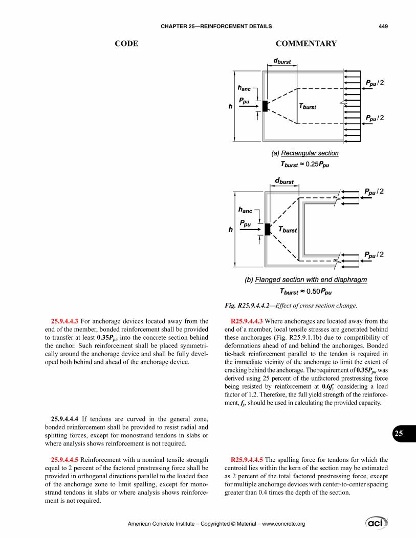
R25.9.4.4.3 Where anchorages are located away from the end of a member, local tensile stresses are generated behind these anchorages (Fig. R25.9.1.1b) due to compatibility of deformations ahead of and behind the anchorages. Bonded tie-back reinforcement parallel to the tendon is required in the immediate vicinity of the anchorage to limit the extent of cracking behind the anchorage. The requirement of 0.35Ppu was derived using 25 percent of the unfactored prestressing force being resisted by reinforcement at 0.6fy considering a load factor of 1.2. Therefore, the full yield strength of the reinforce-ment, fy, should be used in calculating the provided capacity.
R25.9.4.4.5 The spalling force for tendons for which the centroid lies within the kern of the section may be estimated as 2 percent of the total factored prestressing force, except for multiple anchorage devices with center-to-center spacing greater than 0.4 times the depth of the section.
25.9.4.4.3 For anchorage devices located away from the end of the member, bonded reinforcement shall be provided to transfer at least 0.35Ppu into the concrete section behind the anchor. Such reinforcement shall be placed symmetri-cally around the anchorage device and shall be fully devel-oped both behind and ahead of the anchorage device.
25.9.4.4.4 If tendons are curved in the general zone, bonded reinforcement shall be provided to resist radial and splitting forces, except for monostrand tendons in slabs or where analysis shows reinforcement is not required.
25.9.4.4.5 Reinforcement with a nominal tensile strength equal to 2 percent of the factored prestressing force shall be provided in orthogonal directions parallel to the loaded face of the anchorage zone to limit spalling, except for mono-strand tendons in slabs or where analysis shows reinforce-ment is not required.
Fig. R25.9.4.4.2—Effect of cross section change.
American Concrete Institute – Copyrighted © Material – www.concrete.org
CHAPTER 25—REINFORCEMENT DETAILS 449
CODE COMMENTARY
25
R25.9.4.4.6 For monostrand slab tendons, the general-zone minimum reinforcement requirements are based on the recommendations of ACI 423.3R, which were based on Breen et al. (1994). Typical details are shown in Fig. R25.9.4.4.6. The horizontal bars parallel to the edge required by 25.9.4.4.6(a) should be continuous where possible.
The tests on which the recommendations of Breen et al. (1994) were based were limited to anchorage devices for 12.7 mm diameter, 1860 MPa strand, and unbonded tendons in normalweight concrete. Thus, for larger strand anchorage devices and for use in lightweight concrete slabs, ACI Committee 423 recommended that the amount and spacing of reinforcement should be conservatively adjusted to provide for the larger anchorage force and smaller split-ting tensile strength of lightweight concrete (ACI 423.3R).
ACI 423.3R and Breen et al. (1994) both recommend that hairpin bars also be furnished for anchorages located within 300 mm of slab corners to resist edge tension forces. The meaning of “ahead of” in 25.9.4.4.6 is illustrated in Fig. R25.9.1.1b.
In those cases where multistrand anchorage devices are used for slab tendons, all provisions of 25.9.4 are to be satisfied.
The reinforcement perpendicular to the plane of the slab required by 25.9.4.4.6(b) for groups of relatively closely spaced tendons should also be provided in the case of widely spaced tendons.
25.9.4.4.6 For monostrand anchorage devices for 12.7 mm or smaller diameter strands in normalweight concrete slabs, reinforcement satisfying (a) and (b) shall be provided in the general zone, unless a detailed analysis in accordance with 25.9.4.3 shows that this reinforcement is not required:
(a) Two horizontal bars at least No. 13 in size shall be provided parallel to the slab edge. They shall be permitted to be in contact with the front face of the anchorage device and shall be within a distance of h/2 ahead of each device. Those bars shall extend at least 150 mm either side of the outer edges of each device.(b) If the center-to-center spacing of anchorage devices is 300 mm or less, the anchorage devices shall be consid-ered as a group. For each group of six or more anchorage devices, n + 1 hairpin bars or closed stirrups at least No. 10 in size shall be provided, where n is the number of anchorage devices. One hairpin bar or stirrup shall be placed between each anchorage device and one on each side of the group. The hairpin bars or stirrups shall be placed with the legs extending into the slab perpendicular to the edge. The center portion of the hairpin bars or stir-rups shall be placed perpendicular to the plane of the slab from 3h/8 to h/2 ahead of the anchorage devices.
American Concrete Institute – Copyrighted © Material – www.concrete.org
450 BUILDING CODE REQUIREMENTS FOR STRUCTURAL CONCRETE (ACI 318M-14) AND COMMENTARY (ACI 318RM-14)
CODE COMMENTARY
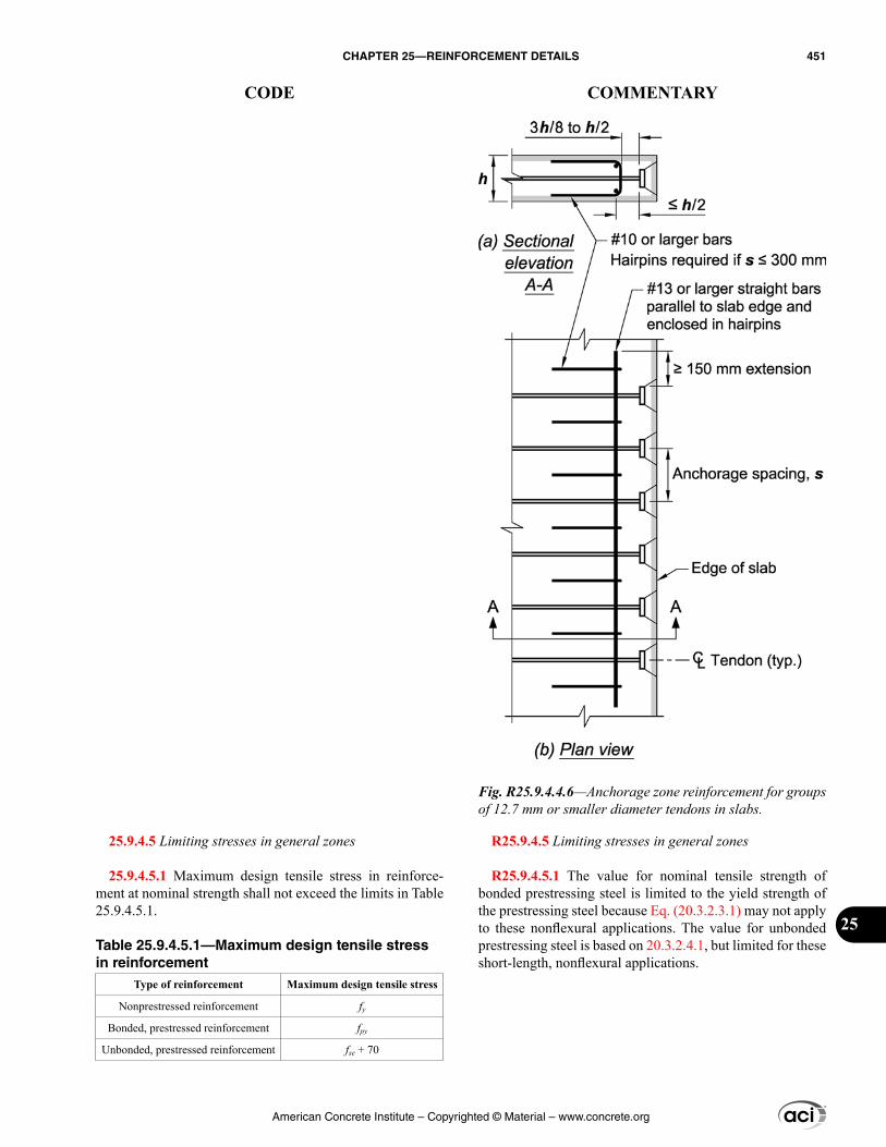
R25.9.4.5 Limiting stresses in general zones
R25.9.4.5.1 The value for nominal tensile strength of bonded prestressing steel is limited to the yield strength of the prestressing steel because Eq. (20.3.2.3.1) may not apply to these nonflexural applications. The value for unbonded prestressing steel is based on 20.3.2.4.1, but limited for these short-length, nonflexural applications.
25.9.4.5 Limiting stresses in general zones
25.9.4.5.1 Maximum design tensile stress in reinforce-ment at nominal strength shall not exceed the limits in Table 25.9.4.5.1.
Table 25.9.4.5.1—Maximum design tensile stress in reinforcement
Type of reinforcement Maximum design tensile stress
Nonprestressed reinforcement fy
Bonded, prestressed reinforcement fpy
Unbonded, prestressed reinforcement fse + 70
Fig. R25.9.4.4.6—Anchorage zone reinforcement for groups of 12.7 mm or smaller diameter tendons in slabs.
American Concrete Institute – Copyrighted © Material – www.concrete.org
CHAPTER 25—REINFORCEMENT DETAILS 451
CODE COMMENTARY
25
25.9.4.5.2 Compressive stress in concrete at nominal strength shall not exceed 0.7λfci′, where λ is defined in 19.2.4.
25.9.4.5.3 If concrete is confined by spirals or hoops and the effect of confining reinforcement is documented by tests and analysis, it shall be permitted to use an increased value of compressive stress in concrete when calculating the nominal strength of the general zone.
25.9.4.5.4 Prestressing reinforcement shall not be stressed until compressive strength of concrete, as indicated by tests of cylinders cured in a manner consistent with curing of the member, is at least 17 MPa for single-strand or bar tendons or at least 28 MPa for multistrand tendons unless 25.9.4.5.5 is satisfied.
25.9.4.5.5 Provisions of 25.9.4.5.4 need not be satisfied if (a) or (b) is satisfied:
(a) Oversized anchorage devices are used to compensate for a lower concrete compressive strength(b) Prestressing reinforcement is stressed to no more than 50 percent of the final prestressing force
25.9.5 Reinforcement detailing
25.9.5.1 Selection of reinforcement size, spacing, cover, and other details for anchorage zones shall make allowances for tolerances on fabrication and placement of reinforce-ment; for the size of aggregate; and for adequate placement and consolidation of the concrete.
R25.9.4.5.2 Some inelastic deformation of concrete within general zones is expected because anchorage zone design is based on a strength approach. The inclusion of the λ factor for lightweight concrete reflects its lower tensile strength, which is an indirect factor in limiting compressive stresses, as well as the wide scatter and brittleness exhibited in some lightweight concrete anchorage zone tests.
R25.9.4.5.3 For well-confined concrete, the effective compressive strength may be increased (Breen et al. 1994). Test results given in Breen et al. (1994) indicate that the compressive stress introduced by auxiliary prestressing applied perpendicular to the axis of the main tendons can be effective in increasing anchorage zone strength.
R25.9.4.5.4 To limit early shrinkage cracking, mono-strand tendons are sometimes stressed at concrete strengths less than 17 MPa. In such cases, either oversized monostrand anchorages are used, or the strands are stressed in stages, often to levels one-third to one-half of the final prestressing force as permitted by 25.9.4.5.5.
American Concrete Institute – Copyrighted © Material – www.concrete.org
452 BUILDING CODE REQUIREMENTS FOR STRUCTURAL CONCRETE (ACI 318M-14) AND COMMENTARY (ACI 318RM-14)
CODE COMMENTARY

CHAPTER 26—CONSTRUCTION DOCUMENTS AND INSPECTION
26.1—Scope
R26—CONSTRUCTION DOCUMENTS AND INSPECTION
R26.1—Scope This chapter establishes the minimum requirements
for information that must be included in the construction documents as applicable to the project. The requirements include information developed in the structural design that must be conveyed to the contractor, provisions directing the contractor on required quality, and inspection requirements to verify compliance with the construction documents. In previous editions of the Code through 2011, these provisions were located throughout the document. Starting with the 2014 edition, with the exception of Chapter 17, all provisions relating to construction have been gathered into this chapter for use by the licensed design professional. Construction- and inspection-related provisions associated with anchors are in Chapter 17 and are called out within Sections 26.7 and 26.13, as appropriate.
This chapter is directed to the licensed design professional responsible for incorporating project requirements into the construction documents. The construction documents should contain all of the necessary design and construction requirements for the contractor to achieve compliance with the Code. It is not intended that the Contractor will need to read and interpret the Code.
A general reference in the construction documents requiring compliance with this Code is to be avoided because the contractor is rarely in a position to accept responsibility for design details or construction requirements that depend on detailed knowledge of the design. References to specific Code provisions should be avoided as well because it is the intention of the Code that all necessary provisions be included in the construction documents. For example, refer-ences to specific provisions within Chapter 26 are expected to be replaced with the appropriate references within the project construction documents. Reference to ACI and ASTM standards as well as to other documents is expected.
This chapter includes provisions for some of the informa-tion that is to be in the construction documents. This chapter is not intended as an all-inclusive list; additional items may be applicable to the Work or required by the building offi-cial. ACI 301 is a reference construction specification that is written to be consistent with the requirements of this Code.
It is recognized that there are situations, such as those in precast or post-tensioned structures, where design and detailing of portions of the Work are delegated to specialty engineers or contractors who may retain the services of a specialty engineer. Such specialty engineers should be licensed design professionals who are sufficiently knowl-edgeable in the design and construction of the structural items being delegated for design.
American Concrete Institute – Copyrighted © Material – www.concrete.org
CHAPTER 26—CONSTRUCTION DOCUMENTS AND INSPECTION 453
CODE COMMENTARY
26
Chapter 26 is organized as shown below:
Section Coverage
26.1 Scope
26.2 Design criteria
26.3 Member information
26.4 Concrete materials and mixture requirements
26.5 Concrete production and construction
26.6 Reinforcement materials and construction requirements
26.7 Anchoring to concrete
26.8 Embedments
26.9 Additional requirements for precast concrete
26.10 Additional requirements for prestressed concrete
26.11 Formwork
26.12 Concrete evaluation and acceptance
26.13 Inspection
R26.1.1 Chapter 17, Anchoring to Concrete, also contains design information, compliance requirements, and inspec-tion requirements for anchoring to concrete.
R26.1.1(a) and (b) Except for the inspection require-ments of 26.13, the provisions of this chapter are organized by design information and compliance requirements.
Design information is project specific and developed during the structural design. It describes the basis of the design or provides information regarding the construction of the Work. Only design information that is applicable to the Work need be provided.
Compliance requirements are general provisions that provide a minimum acceptable level of quality for construction of the Work. It is not the intent of the Code to require the licensed design professional to incorporate verbatim the compliance requirements into the construction documents. Some of these requirements may not be applicable to a specific project.
Construction documents that incorporate the minimum applicable compliance requirements of this chapter are considered to comply with the Code, even if the require-ments are stated differently, exceed these minimum require-ments, or provide more detail.
R26.1.1(c) Section 26.13 provides inspection provisions to be used in the absence of general building code inspec-tion provisions. These inspection requirements are intended to provide verification that the Work complies with the construction documents.
The inspection requirements of the governing jurisdic-tion or the general building code take precedence over those included in this chapter. Refer to 26.13.1. ACI 311.4R provides guidance for inspection of concrete construction, and ACI 311.6 is a reference specification for testing services for ready mixed concrete.
26.1.1 This chapter addresses (a) through (c):
(a) Design information that the licensed design profes-sional shall specify in the construction documents, if applicable.(b) Compliance requirements that the licensed design professional shall specify in the construction documents, if applicable.
(c) Inspection requirements that the licensed design professional shall specify in the construction documents, if applicable.
American Concrete Institute – Copyrighted © Material – www.concrete.org
454 BUILDING CODE REQUIREMENTS FOR STRUCTURAL CONCRETE (ACI 318M-14) AND COMMENTARY (ACI 318RM-14)
CODE COMMENTARY
R26.2—Design criteria
R26.2.1(a) and (b) Reference to the applicable version of the documents that govern the design including essential loading information, such as gravity and lateral loading, is to be included in the construction documents.
R26.2.1(c) The licensed design professional often dele-gates the design of portions of the structure to a specialty engineer, such as one retained by the contractor. The licensed design professional should provide the necessary information for the completion of this design consistent with the overall design of the structure. This information includes design loads that impact the delegated design work. An example is earthquake design criteria for precast concrete fascia panel connections to provide compatibility with the overall structural system.
R26.3—Member information
R26.3.1(a) Construction tolerances for member size and location can be incorporated in construction documents by reference to ACI 117 for cast-in-place construction or to ACI ITG-7 for precast construction. Specific project toler-ances that are more restrictive or that are not covered in these references should also be included in the construction documents.
R26.4—Concrete materials and mixture requirements
26.2—Design criteria 26.2.1 Design information:
(a) Name and year of issue of the Code, general building code, and any supplements governing design.(b) Loads used in design.
(c) Design work delegated to the contractor including applicable design criteria.
26.3—Member information 26.3.1 Design information:
(a) Member size, location, and related tolerances.
26.4—Concrete materials and mixture requirements
26.4.1 Concrete materials
26.4.1.1 Cementitious materials
26.4.1.1.1 Compliance requirements:
(a) Cementitious materials shall conform to the specifica-tions in Table 26.4.1.1.1(a).
Table 26.4.1.1.1(a)—Specifications for cementitious materials
Cementitious material Specification
Portland cement ASTM C150M
Blended hydraulic cements ASTM C595M, excluding Type IS (≥70) and Type IT (S ≥ 70)
Expansive hydraulic cement ASTM C845M
Hydraulic cement ASTM C1157M
Fly ash and natural pozzolan ASTM C618
Slag cement ASTM C989M
Silica fume ASTM C1240
American Concrete Institute – Copyrighted © Material – www.concrete.org
CHAPTER 26—CONSTRUCTION DOCUMENTS AND INSPECTION 455
CODE COMMENTARY
26
R26.4.1.2 Aggregates
R26.4.1.2.1(b) Aggregates conforming to ASTM specifi-cations are not always economically available and, in some instances, materials that do not conform to ASTM C33M or C330M may have a documented history of satisfactory performance under similar exposure. Such nonconforming materials are permitted if acceptable evidence of satisfactory performance is provided. Generally, aggregates conforming to the designated specifications should be used.
R26.4.1.3 Water—Almost any natural water that is potable and has no pronounced taste or odor is satisfactory as mixing water for making concrete. Excessive impurities in mixing water may affect setting time, concrete strength, and volume stability, and may also cause efflorescence or corrosion of reinforcement.
Salts or other deleterious substances contributed from the aggregate or admixtures add to those that might be contained in the mixing water. These additional amounts are to be considered in establishing the total impurities that may be present in the concrete.
R26.4.1.3.1(a) ASTM C1602M allows the use of potable water without testing and includes methods for qualifying nonpotable sources of water, such as from concrete produc-tion operations, with consideration of effects on setting time and strength. Testing frequencies are established to ensure continued monitoring of water quality.
ASTM C1602M includes optional limits for chlorides, sulfates, alkalis, and solids in mixing water that can be invoked if appropriate.
R26.4.1.4 Admixtures
R26.4.1.4.1(a) ASTM C494M includes Type S—specific performance admixtures—that can be specified if perfor-mance characteristics not listed in 26.4.1.4.1(a) are desired, such as viscosity-modifying admixtures. The basic require-ment for a Type S admixture is that it will not have adverse effects on the properties of concrete when tested in accordance with ASTM C494M. Meeting the requirements of Type S does not ensure that the admixture will perform its described function. The manufacturer of an admixture presented as
(b) All cementitious materials specified in Table 26.4.1.1.1(a) and the combinations of these materials shall be included in calculating the w/cm of the concrete mixture.
26.4.1.2 Aggregates
26.4.1.2.1 Compliance requirements:
(a) Aggregates shall conform to (1) or (2):(1) Normalweight aggregate: ASTM C33M.(2) Lightweight aggregate: ASTM C330M.
(b) Aggregates not conforming to ASTM C33M or ASTM C330M are permitted if they have been shown by test or actual service to produce concrete of adequate strength and durability and are approved by the building official.
26.4.1.3 Water
26.4.1.3.1 Compliance requirements:
(a) Mixing water shall conform to ASTM C1602M.(b) Mixing water, including that portion of mixing water contributed in the form of free moisture on aggregates, shall not contain deleterious amounts of chloride ion when used for prestressed concrete, for concrete that will contain aluminum embedments, or for concrete cast against stay-in-place galvanized steel forms.
26.4.1.4 Admixtures
26.4.1.4.1 Compliance requirements:
(a) Admixtures shall conform to (1) through (4):(1) Water reduction and setting time modification: ASTM C494M.(2) Producing flowing concrete: ASTM C1017M.(3) Air entrainment: ASTM C260M.(4) Inhibiting chloride-induced corrosion: ASTM C1582M.
American Concrete Institute – Copyrighted © Material – www.concrete.org
456 BUILDING CODE REQUIREMENTS FOR STRUCTURAL CONCRETE (ACI 318M-14) AND COMMENTARY (ACI 318RM-14)
CODE COMMENTARY
conforming to Type S should also be required to provide data that the product will meet the performance claimed.
R26.4.1.4.1(c) Calcium chloride is prohibited from use in prestressed concrete because corrosion of prestressing rein-forcement is generally of greater concern than corrosion of nonprestressed reinforcement. Local reduction in the cross section of the prestressing steel may result in fracture of the steel (ACI 222R).
The presence of chloride ions may cause corrosion of embedded aluminum such as conduit, especially if the aluminum is in contact with embedded steel and the concrete is in a humid environment. Protection require-ments for embedded aluminum are given in 26.8.2. Corro-sion of galvanized steel sheet and galvanized steel stay-in-place forms may occur, especially in humid environments or where drying is inhibited by the thickness of the concrete or coatings or impermeable coverings. Specific limits on chlo-ride ion concentration in concrete are given in 19.3.2.1.
R26.4.1.4.1(d) In some cases, the use of admixtures in concrete containing ASTM C845M expansive cements has resulted in reduced levels of expansion or increased shrinkage values. Refer to ACI 223R.
R26.4.1.5 Steel fiber reinforcement
R26.4.1.5.1(a) Deformations in steel fibers enhance mechanical anchorage with the concrete. The limits for the fiber length-to-diameter ratio are based on available test data (Parra-Montesinos 2006). Because data are not avail-able on the potential for corrosion problems due to galvanic action, the use of deformed steel fibers in members rein-forced with stainless-steel bars or galvanized steel bars is not recommended.
R26.4.2 Concrete mixture requirements
R26.4.2.1(a) The requirements for each concrete mixture used for the Work are to be stated in the construction docu-ments. These are determined from applicable concrete design requirements in 19.2 and durability requirements in 19.3. The most restrictive requirements that apply are to be stated.
R26.4.2.1(a)(4) The size limitations on aggregates are provided to facilitate placement of concrete around the reinforcement without honeycombing due to blockage by closely-spaced reinforcement. It is the intent of the Code
(b) Admixtures that do not conform to the specifications in 26.4.1.4.1(a) shall be subject to prior review by the licensed design professional.(c) Calcium chloride or admixtures containing chloride from sources other than impurities in admixture ingredi-ents shall not be used in prestressed concrete, in concrete containing embedded aluminum, or in concrete cast against stay-in-place galvanized steel forms.
(d) Admixtures used in concrete containing expansive cements conforming to ASTM C845M shall be compat-ible with the cement and produce no deleterious effects.
26.4.1.5 Steel fiber reinforcement
26.4.1.5.1 Compliance requirements:
(a) Steel fiber reinforcement used for shear resistance shall satisfy (1) and (2):
(1) Be deformed and conform to ASTM A820M.(2) Have a length-to-diameter ratio of at least 50 and not exceeding 100.
26.4.2 Concrete mixture requirements
26.4.2.1 Design information:
(a) Requirements (1) through (11) for each concrete mixture, based on assigned exposure classes or design of members:
(1) Minimum specified compressive strength of concrete, fc′.(2) Test age for demonstrating compliance with fc′ if different from 28 days.(3) Maximum w/cm applicable to most restrictive assigned durability exposure class from 19.3.2.1.(4) Nominal maximum size of coarse aggregate not to exceed the least of (i), (ii), and (iii):
(i) one-fifth the narrowest dimension between sides of forms
American Concrete Institute – Copyrighted © Material – www.concrete.org
CHAPTER 26—CONSTRUCTION DOCUMENTS AND INSPECTION 457
CODE COMMENTARY
26
(ii) one-third the depth of slabs(iii) three-fourths the minimum specified clear spacing between individual reinforcing bars or wires, bundles of bars, prestressed reinforcement, individual tendons, bundled tendons, or ducts
These limitations shall not apply if, in the judgment of the licensed design professional, workability and methods of consolidation are such that concrete can be placed without honeycombs or voids.
(5) For members assigned to Exposure Category F, air content from 19.3.3.1.(6) For members assigned to Exposure Class C, appli-cable chloride ion limits for assigned Exposure Class from 19.3.2.1.(7) For members assigned to Exposure Category S, type of cementitious materials for assigned Exposure Class from 19.3.2.1.(8) For members assigned to Exposure Class S2 or S3, admixtures containing calcium chloride are prohibited.(9) Equilibrium density of lightweight concrete.
(10) Requirement for submittal of the volumetric frac-tions of aggregate in lightweight concrete mixtures for the verification of λ value if used in design.(11) If used for shear resistance in accordance with 9.6.3.1, requirements for steel fiber-reinforced concrete.
(b) At the option of the licensed design professional, exposure classes based on the severity of the anticipated exposure of members.
that the licensed design professional select the appropriate nominal maximum size aggregate and include this value in the construction documents for each concrete mixture. Because maximum aggregate size can impact concrete prop-erties such as shrinkage, and also the cost of concrete, the largest aggregate size consistent with the requirements of 26.4.2.1 should be permitted. Increasing aggregate size will only decrease shrinkage if there is a concurrent reduction in paste volume.
R26.4.2.1(a)(5) ASTM C94M and ASTM C685M include a tolerance for air content as delivered of ±1.5 percentage points.
R26.4.2.1(a)(9) Equilibrium density is an estimate of the density of lightweight concrete assuming some degree of drying after initial construction. The equilibrium density of lightweight concrete is determined in accordance with ASTM C567M. Based on an established correlation between the density of fresh concrete and equilibrium density, light-weight concrete is accepted at time of delivery on the basis of density of the fresh concrete.
R26.4.2.1(a)(11) If steel fibers are used for shear resis-tance, there are specific requirements for the steel fiber-rein-forced concrete: 26.4.1.5.1(a) provides fiber requirements; 26.4.2.2(d) provides minimum dosage requirements; and 26.12.5.1(a) provides acceptance criteria. Fibers are typi-cally specified by fiber type, fiber length, aspect ratio (ℓ/d), and dosage rate (ACI 544.3R).
For structural applications, the Code only addresses the use of discontinuous deformed steel fibers in resisting shear. For other structural applications where it is desired to use discontinuous deformed steel fibers, Section 1.10 provides a procedure for approval. Also, there are nonstructural appli-cations or functional purposes where discontinuous steel fibers are used in concrete. The provisions of the Code that address use of steel fibers for shear strength are not intended for such nonstructural applications.
R26.4.2.1(b) Durability requirements for concrete are based on exposure classification of members as given in 19.3. Therefore, the exposure classes applicable to the members establish the basis for the requirements for concrete mixtures. Section 19.3.1 requires the licensed design profes-sional to assign exposure classes for different members in the structure. Concrete mixtures should be specified accord-
American Concrete Institute – Copyrighted © Material – www.concrete.org
458 BUILDING CODE REQUIREMENTS FOR STRUCTURAL CONCRETE (ACI 318M-14) AND COMMENTARY (ACI 318RM-14)
CODE COMMENTARY
(c) The required compressive strength at designated stages of construction for each part of the structure designed by the licensed design professional.
26.4.2.2 Compliance requirements:
(a) The required compressive strength at designated stages of construction for each part of the structure not designed by the licensed design professional shall be submitted for review.(b) The maximum percentage of pozzolans, including fly ash and silica fume, and slag cement in concrete assigned to Exposure Class F3, shall be in accordance with Table 26.4.2.2(b) and (1) and (2).
(1) The maximum percentage limits in Table 26.4.2.2(b) shall include the fly ash or other pozzolans, slag cement, and silica fume used in the manufacture of ASTM C595M and C1157M blended cements.(2) The individual limits in Table 26.4.2.2(b) shall apply regardless of the number of cementitious materials in a concrete mixture.
Table 26.4.2.2(b)—Limits on cementitious materials for concrete assigned to Exposure Class F3
Cementitious materials
Maximum percent of total cementitious materials by
massFly ash or other pozzolans conforming to ASTM C618 25
Slag cement conforming to ASTM C989M 50
Silica fume conforming to ASTM C1240 10
Total of fly ash or other pozzolans and silica fume 35
Total of fly ash or other pozzolans, slag cement, and silica fume 50
ingly, but the Code does not require the assigned exposure classes to be explicitly stated in the construction documents. If the licensed design professional is requiring the contractor to determine concrete properties by specifying ACI 301, the assigned exposure classes for all members will need to be stated explicitly in the construction documents.
R26.4.2.1(c) If design or construction requirements dictate that in-place strength of concrete be achieved at specific ages or stages of construction, these requirements should be stated explicitly in the construction documents. Typical stages of construction when the required compressive strength of concrete needs to be specified include at removal of form-work and shores. Additionally, required compressive strength of concrete should be specified for: 1) cast-in-place post-tensioned concrete at the application of post-tensioning; 2) precast concrete at stripping from the forms and during handling, shipping, and erection; and 3) precast, prestressed concrete at transfer of prestress, at stripping from the forms, and during handling, shipping, and erection.
For portions of the structure that are not designed by the licensed design professional, refer to 26.4.2.2(a).
American Concrete Institute – Copyrighted © Material – www.concrete.org
CHAPTER 26—CONSTRUCTION DOCUMENTS AND INSPECTION 459
CODE COMMENTARY
26
(c) For concrete exposed to sulfate, alternative combi-nations of cementitious materials to those specified in 26.4.2.1(a)(7) are permitted if tests for sulfate resistance satisfy the criteria in Table 26.4.2.2(c).
Table 26.4.2.2(c)—Requirements for establishing suitability of combinations of cementitious materials exposed to water-soluble sulfate
Exposure class
Maximum expansion strain if tested using ASTM C1012M
At 6 months At 12 months At 18 months
S1 0.10 percent No requirement No requirement
S2 0.05 percent 0.10 percent[1] No requirement
S3 No requirement No requirement 0.10 percent
[1]The 12-month expansion limit applies only if the measured expansion exceeds the 6-month maximum expansion limit.
(d) Steel fiber-reinforced concrete used for shear resis-tance shall satisfy (1) and (2):
(1) Conform to ASTM C1116M.(2) Contain at least 60 kg of deformed steel fibers per cubic meter of concrete.
26.4.3 Proportioning of concrete mixtures
26.4.3.1 Compliance requirements:
(a) Concrete mixture proportions shall be established so that the concrete satisfies (1) through (3):
(1) Can be placed readily without segregation into forms and around reinforcement under anticipated placement conditions.(2) Meets requirements for assigned exposure class in accordance with either 26.4.2.1(a) or 26.4.2.1(b).(3) Conforms to strength test requirements for standard-cured specimens.
R26.4.2.2(c) Mixture requirements for Exposure Cate-gory S are given in 19.3.2.1. ASTM C1012M may be used to evaluate the sulfate resistance of concrete mixtures using alternative combinations of cementitious materials to those listed in Table 19.3.2.1 for all classes of sulfate exposure. More detailed guidance on qualification of such mixtures using ASTM C1012M is given in ACI 201.2R. The expan-sion criteria in Table 26.4.2.2(c) for testing according to ASTM C1012M are the same as those in ASTM C595M for moderate sulfate resistance (Optional Designation MS) in Exposure Class S1 and for high sulfate resistance (Optional Designation HS) in Exposure Class S2, and the same as in ASTM C1157M for Type MS in Exposure Class S1 and Type HS in Exposure Class S2.
R26.4.3 Proportioning of concrete mixtures—The 2014 edition of the Code does not include the statistical require-ments for proportioning concrete that were contained in previous editions. This information was removed from the Code because it is not the responsibility of the licensed design professional to proportion concrete mixtures. Further, this information is available in other ACI documents, such as ACI 301 and ACI 214R. Finally, the quality control proce-dures of some concrete producers allow meeting the accep-tance criteria of the Code without following the process included in previous editions of the Code.
R26.4.3.1(a) This section provides requirements for developing mixture proportions. The concrete is required to be workable and to meet the durability and strength requirements of the Code. The term “without segregation” is intended to provide for a cohesive mixture in which aggre-gates remain well distributed while the concrete is in its fresh state. It is recognized that some segregation in the form of bleeding will occur. The required workability will depend on reinforcement congestion, member geometry, and the placement and consolidation methods to be used. Construc-tion requirements of the contractor should be considered in establishing required workability of the concrete.
The Code does not include provisions for especially severe exposures, such as chemical contact, high temperatures, temporary freezing-and-thawing conditions during construc-tion, abrasive conditions, alkali-aggregate reactions, or other unique durability considerations pertinent to the structure. The Code also does not address aesthetic considerations
American Concrete Institute – Copyrighted © Material – www.concrete.org
460 BUILDING CODE REQUIREMENTS FOR STRUCTURAL CONCRETE (ACI 318M-14) AND COMMENTARY (ACI 318RM-14)
CODE COMMENTARY
(b) Concrete mixture proportions shall be established in accordance with Article 4.2.3 of ACI 301 or by an alterna-tive method acceptable to the licensed design professional. Alternative methods shall have a probability of satisfying the strength requirements for acceptance tests of standard-cured specimens that meets or exceeds the probability associated with the method in Article 4.2.3 of ACI 301. If Article 4.2.3 of ACI 301 is used, the strength test records used for establishing and documenting concrete mixture proportions shall not be more than 24 months old.
(c) The concrete materials used to develop the concrete mixture proportions shall correspond to those to be used in the proposed Work.
(d) If different concrete mixtures are to be used for different portions of proposed Work, each mixture shall comply with the concrete mixture requirements stated in the construction documents.
26.4.4 Documentation of concrete mixture characteristics
26.4.4.1 Compliance requirements:(a) Documentation of concrete mixture characteristics shall be submitted for review by the licensed design professional before the mixture is used and before making changes to mixtures already in use. Evidence of the ability of the proposed mixture to comply with the concrete mixture requirements in the construction documents shall be included in the documentation. The evidence shall be based on field test records or laboratory trial batches. Field test records shall represent conditions similar to those anticipated during the proposed Work.
(b) If field or laboratory test data are not available, and fc′ ≤ 35 MPa, concrete proportions shall be based on other experience or information, if approved by the licensed design professional. If fc′ > 35 MPa, test data docu-menting the characteristics of the proposed mixtures are required.
such as surface finishes. If applicable, these items should be covered specifically in the construction documents.
Strength test requirements for standard-cured specimens are given in 26.12.3.
R26.4.3.1(b) Article 4.2.3 of ACI 301 contains the statis-tical procedures for selecting the required average strength that were included previously in the Code. Alternatively, the concrete producer may provide evidence acceptable to the licensed design professional that the concrete can be propor-tioned by another method to meet the project requirements and the acceptance criteria of 26.12.3. The Code presumes that the probability of not meeting the acceptance criteria in 26.12.3 is not more than 1 in 100. Following the method of proportioning in ACI 301 will maintain this level of risk. A key factor in evaluating any proposed alternative propor-tioning method should be its ability to preserve this presumed level of risk. Refer to ACI 214R for additional information.
R26.4.3.1(d) If more than one concrete mixture is used for the project, each mixture is required to satisfy Code require-ments. A change in concrete constituents, such as sources or types of cementitious materials, aggregates, or admix-tures, is considered a different mixture. A minor change in mixture proportions made in response to field conditions is not considered a new mixture.
Concrete mixture requirements to be placed in the construction documents are given in 26.4.2.1(a).
R26.4.4 Documentation of concrete mixture characteristics
R26.4.4.1(a) Review of the proposed concrete mixture is necessary to ensure that it is appropriate for the project and meets all of the requirements for strength and durability as established by the licensed design professional. The licensed design professional typically reviews the documentation on a proposed concrete mixture to evaluate the likelihood that the concrete will meet the strength-test acceptance require-ments of 26.12.3 and that acceptable materials are used. The statistical principles discussed in ACI 214R can be useful in evaluating the likelihood that a proposed mixture will meet the strength-test requirements of 26.12.3.
Concrete mixture requirements to be placed in the construction documents are given in 26.4.2.1(a).
R26.4.4.1(b) If fc′ ≤ 35 MPa and test data are not avail-able, concrete mixture proportions should be established to produce a sufficiently high average strength such that the likelihood that the concrete would not meet the strength acceptance criteria would be acceptably low. Guidance on an appropriate average strength is provided in ACI 214R. The
American Concrete Institute – Copyrighted © Material – www.concrete.org
CHAPTER 26—CONSTRUCTION DOCUMENTS AND INSPECTION 461
CODE COMMENTARY
26
(c) If data become available during construction that consistently exceed the strength-test acceptance criteria for standard-cured specimens, it shall be permitted to modify a mixture to reduce the average strength. Submit evidence acceptable to the licensed design professional to demonstrate that the modified mixture will comply with the concrete mixture requirements in the construction documents.
26.5—Concrete production and construction
26.5.1 Concrete production
26.5.1.1 Compliance requirements:
(a) Cementitious materials and aggregates shall be stored to prevent deterioration or contamination.(b) Material that has deteriorated or has been contami-nated shall not be used in concrete.(c) Equipment for mixing and transporting concrete shall conform to ASTM C94M or ASTM C685M.
(d) Ready-mixed and site-mixed concrete shall be batched, mixed, and delivered in accordance with ASTM C94M or ASTM C685M.
26.5.2 Concrete placement and consolidation
26.5.2.1 Compliance requirements:
(a) Debris and ice shall be removed from spaces to be occupied by concrete before placement.
(b) Standing water shall be removed from place of deposit before concrete is placed unless a tremie is to be used or unless otherwise permitted by both the licensed design professional and the building official.
purpose of this provision is to allow construction to continue when there is an unexpected interruption in concrete supply and there is not sufficient time for testing and evaluation. It also applies for a small project where the cost of trial mixture data is not justified.
R26.4.4.1(c) Often, at the beginning of a project, concrete mixtures will be proportioned conservatively to ensure passing the strength-test acceptance criteria. As test data showing actual variability become available, it may be appropriate to proportion the mixture less conservatively. Refer to ACI 214R for guidance.
Concrete mixture requirements to be placed in the construction documents are given in 26.4.2.1(a).
R26.5—Concrete production and construction Detailed recommendations for mixing, handling, trans-
porting, and placing concrete are given in ACI 304R.
R26.5.1 Concrete production
R26.5.1.1(c) ASTM C94M and ASTM C685M address oper-ational requirements for equipment used to produce concrete.
R26.5.1.1(d) ASTM C94M is a specification for ready mixed concrete whereby materials are primarily measured by mass (weight) and production is by batches. This is the more common method of concrete production, and it is also used in precast concrete plants. ASTM C685M is a specifi-cation for concrete where materials are measured by volume and the production is by continuous mixing. These specifica-tions include provisions for capacity of mixers, accuracy of measuring devices, batching accuracy, mixing and delivery, and tests for evaluating the uniformity of mixed concrete.
R26.5.2 Concrete placement and consolidation
R26.5.2.1(a) Forms need to be cleaned before beginning to place concrete. In particular, sawdust, nails, wood pieces, and other debris that may collect inside forms need to be removed.
R26.5.2.1(b) The tremie referred to in this provision is not a short tube or “elephant trunk.” It is a full-depth pipe used in accordance with accepted procedures for placing concrete under water. Information regarding placing concrete using a tremie is given in ACI 304R.
American Concrete Institute – Copyrighted © Material – www.concrete.org
462 BUILDING CODE REQUIREMENTS FOR STRUCTURAL CONCRETE (ACI 318M-14) AND COMMENTARY (ACI 318RM-14)
CODE COMMENTARY
R26.5.2.1(d) The Code requires the equipment for handling and transporting concrete to be capable of supplying concrete to the place of deposit continuously and reliably under all conditions and for all methods of place-ment. This applies to all placement methods, including pumps, belt conveyors, pneumatic systems, wheelbarrows, buggies, crane buckets, and tremies.
R26.5.2.1(e) Loss of strength can result if concrete is pumped through pipe made of aluminum or aluminum alloy. Hydrogen gas generated by the reaction between the cement alkalies and the aluminum eroded from the interior of the pipe surface has been shown to cause strength reduction as much as 50 percent. Hence, equipment made of aluminum or aluminum alloys should not be used for pump lines, tremies, or chutes other than short chutes such as those used to convey concrete from a truck mixer.
R26.5.2.1(f) Concrete should be available at a supply rate consistent with the capacity of the placement equipment and the placement crew. Concrete supplied at a faster rate than can be accommodated by placement equipment or crew can result in loss of workability of concrete in equipment waiting to discharge. Excessive delays in the supply of concrete can cause previous placements to stiffen and result in the forma-tion of cold joints.
Each step in the handling and transporting of concrete needs to be controlled to maintain uniformity within a batch and from batch to batch. It is important to minimize segrega-tion of the coarse aggregate from the mortar or of water from the other ingredients.
Rehandling and transferring concrete over large distances from delivery vehicles to the point of placement in the struc-ture can cause segregation of materials. The Code there-fore requires that concrete be deposited as close to its final location as possible. However, self-consolidating concrete mixtures can be developed to flow longer distances and maintain their stability with minimal segregation. Guidance on self-consolidating concrete is provided in ACI 237R.
R26.5.2.1(h) ASTM C94M permits water addition to mixed concrete before concrete is discharged to bring it up to the specified slump range as long as prescribed limits on the maximum mixing time and w/cm are not violated.
R26.5.2.1(j) Detailed recommendations for consolida-tion of concrete are given in ACI 309R. This guide pres-ents information on the mechanism of consolidation and
(c) Masonry filler units that will be in contact with concrete shall be prewetted prior to placing concrete.(d) Equipment used to convey concrete from the mixer to the location of final placement shall have capabilities to achieve the placement requirements.
(e) Concrete shall not be pumped through pipe made of aluminum or aluminum alloys.
(f) Concrete shall be placed in accordance with (1) through (5):(1) At a rate to provide an adequate supply of concrete at the location of placement.(2) At a rate so concrete at all times has sufficient work-ability such that it can be consolidated by the intended methods.(3) Without segregation or loss of materials.(4) Without interruptions sufficient to permit loss of workability between successive placements that would result in cold joints.(5) Deposited as near to its final location as practicable to avoid segregation due to rehandling or flowing.
(g) Concrete that has been contaminated or has lost its initial workability to the extent that it can no longer be consolidated by the intended methods shall not be used.(h) Retempering concrete in accordance with the limits of ASTM C94M shall be permitted unless otherwise restricted by the licensed design professional.
(i) After starting, concreting shall be carried on as a contin-uous operation until the completion of a panel or section, as defined by its boundaries or predetermined joints.(j) Concrete shall be consolidated by suitable means during placement and shall be worked around reinforce-ment and embedments and into corners of forms.
American Concrete Institute – Copyrighted © Material – www.concrete.org
CHAPTER 26—CONSTRUCTION DOCUMENTS AND INSPECTION 463
CODE COMMENTARY
26
provides recommendations on equipment characteristics and procedures for various types of concrete mixtures.
R26.5.3 Curing concrete—Detailed recommendations for curing concrete are given in ACI 308R. This guide presents basic principles of proper curing and describes the various methods, procedures, and materials for curing of concrete.
R26.5.3.2(c) This section applies whenever an accelerated curing method is used, whether for precast or cast-in-place elements. EB-001.15, and PCI MNL 116, and PCI MNL 117 provide general information on accelerated curing. Acceler-ated curing procedures require careful attention to obtain uniform and satisfactory results. Preventing moisture loss during the curing is essential.
The compressive strength of accelerated-cured concrete is not as high at later ages as that of nominally identical concrete continuously cured under moist conditions at moderate temperatures. Also, the modulus of elasticity, Ec, of accelerated-cured specimens may vary from that of speci-mens moist-cured at normal temperatures.
R26.5.3.2(d) Strengths of cylinders cured under field conditions may be required to evaluate the adequacy of curing and protection of concrete in the structure.
The Code provides a specific criterion in 26.5.3.2(e) for judging the adequacy of curing and protection afforded to the structure. For a valid comparison, field-cured cylinders and companion standard-cured cylinders need to be made from the same sample. Field-cured cylinders are to be cured, as nearly as possible, under the same conditions as the struc-ture. The field-cured cylinders should not be treated more favorably than the structural members they represent.
In evaluating test results of field-cured cylinders, it should be recognized that even if cylinders are protected in the same manner as the structure, they may not experience the same temperature history as the concrete in the structure. This different temperature history occurs because heat of hydra-tion may be dissipated differently in a cylinder compared with the structural member.
(k) Top surfaces of vertically formed lifts shall be gener-ally level.
26.5.3 Curing concrete
26.5.3.1 Design information:
(a) If supplementary tests of field-cured specimens are required to verify adequacy of curing and protection, the number and size of test specimens and the frequency of these supplementary tests.
26.5.3.2 Compliance requirements:
(a) Concrete, other than high-early-strength, shall be maintained at a temperature of at least 10°C and in a moist condition for at least the first 7 days after placement, except if accelerated curing is used.(b) High-early-strength concrete shall be maintained at a temperature of at least 10°C and in a moist condition for at least the first 3 days after placement, except if accelerated curing is used.(c) Accelerated curing to accelerate strength gain and reduce time of curing is permitted using high-pressure steam, steam at atmospheric pressure, heat and moisture, or other process acceptable to the licensed design profes-sional. If accelerated curing is used, (1) and (2) shall apply:
(1) Compressive strength at the load stage considered shall be at least the strength required at that load stage.(2) Accelerated curing shall not impair the durability of the concrete.
(d) If required by the building official or licensed design professional, results of tests of cylinders made and cured in accordance with (1) and (2) shall be provided in addi-tion to results of standard-cured cylinder strength tests.
(1) At least two 150 x 300 mm or at least three 100 x 200 mm field-cured cylinders shall be molded at the same time and from the same samples as standard-cured cylinders;(2) Field-cured cylinders shall be cured in accordance with the field curing procedure of ASTM C31M and tested in accordance with ASTM C39M.
American Concrete Institute – Copyrighted © Material – www.concrete.org
464 BUILDING CODE REQUIREMENTS FOR STRUCTURAL CONCRETE (ACI 318M-14) AND COMMENTARY (ACI 318RM-14)
CODE COMMENTARY
R26.5.3.2(e) Research (Bloem 1968) has shown that the strength of cylinders protected and cured to simulate good field practice should be at least about 85 percent of standard-cured cylinders if both are tested at the age designated for fc′. Thus, a value of 85 percent has been set as a rational basis for judging the adequacy of field curing. The compar-ison is made between the measured strengths of companion field-cured and standard-cured cylinders, not between the strength of field-cured cylinders and the specified value of fc′. Test results for the field-cured cylinders are considered satisfactory, however, if the strength of field-cured cylinders exceeds fc′ by more than 3.5 MPa, even though they fail to reach 85 percent of the strength of companion standard-cured cylinders.
The 85 percent criterion is based on the assumption that concrete is maintained above 10°C and in a moist condition for at least the first 7 days after placement, or high-early-strength concrete is maintained above 10°C and in a moist condition for at least the first 3 days after placement.
If the field-cured cylinders do not provide satisfac-tory strength by this comparison, steps need to be taken to improve the curing. If the tests indicate a possible serious deficiency in strength of concrete in the structure, core tests may be required, with or without supplemental wet curing, to evaluate the structural adequacy, as provided in 26.12.4.
R26.5.4 Concreting in cold weather—Detailed recom-mendations for cold weather concreting are given in ACI 306R. Specification requirements for concreting in cold weather are provided in ACI 301 and ACI 306.1. If both ACI 301 and ACI 306.1 are referenced in construction docu-ments, the governing requirements should be identified.
R26.5.4.1(a) ASTM C94M, ACI 306R, and ACI 301 contain requirements and recommendations for concrete temperature based on section size.
R26.5.5 Concreting in hot weather—Detailed recom-mendations for hot weather concreting are given in ACI 305R. This guide identifies the hot weather factors that affect concrete properties and construction practices and
(e) Procedures for protecting and curing concrete shall be considered adequate if (1) or (2) are satisfied:
(1) Average strength of field-cured cylinders at test age designated for determination of fc′ is equal to or at least 85 percent of that of companion standard-cured cylinders.(2) Average strength of field-cured cylinders at test age exceeds fc′ by more than 3.5 MPa.
26.5.4 Concreting in cold weather
26.5.4.1 Design information:
(a) Temperature limits for concrete as delivered in cold weather.
26.5.4.2 Compliance requirements:
(a) Adequate equipment shall be provided for heating concrete materials and protecting concrete during freezing or near-freezing weather.(b) Frozen materials or materials containing ice shall not be used.(c) Forms, fillers, and ground with which concrete is to come in contact shall be free from frost and ice.(d) Concrete materials and production methods shall be selected so that the concrete temperature at delivery complies with the specified temperature limits.
26.5.5 Concreting in hot weather
American Concrete Institute – Copyrighted © Material – www.concrete.org
CHAPTER 26—CONSTRUCTION DOCUMENTS AND INSPECTION 465
CODE COMMENTARY
26
recommends measures to eliminate or minimize undesir-able effects. Specification requirements for concreting in hot weather are provided in ACI 301 and ACI 305.1.
R26.5.5.1(a) ACI 301 and ACI 305.1 limit the maximum concrete temperature to 35°C at the time of placement.
R26.5.6 Construction, contraction, and isolation joints—For the integrity of the structure, it is important that joints in the structure be located and constructed as required by the design. Any deviations from locations indicated in construc-tion documents should be approved by the licensed design professional.
Construction or other joints should be located where they will cause the least weakness in the structure. Lateral force design may require additional consideration of joints during design.
R26.5.6.1(b) Shear keys, intermittent shear keys, diagonal dowels, or shear friction may be used where force transfer is required. If shear friction at a joint interface in accor-dance with 22.9 is invoked in the design, include applicable construction requirements in the construction documents.
R26.5.6.1(c) The preparations referenced are applicable if design for shear friction is in accordance with 22.9 and for contact surfaces at construction joints for structural walls.
R26.5.6.1(d) The locations referenced are those for which design for shear friction is in accordance with 22.9.
R26.5.6.2(a) If the licensed design professional does not designate specific joint locations, the contractor should
26.5.5.1 Design information:
(a) Temperature limits for concrete as delivered in hot weather.
26.5.5.2 Compliance requirements:
(a) Concrete materials and production methods shall be selected so that the concrete temperature at delivery complies with the specified temperature limits.(b) Handling, placing, protection, and curing procedures shall limit concrete temperatures or water evaporation that could reduce strength, serviceability, and durability of the member or structure.
26.5.6 Construction, contraction, and isolation joints
26.5.6.1 Design information:
(a) If required by the design, locations and details of construction, isolation, and contraction joints.(b) Details required for transfer of shear and other forces through construction joints.
(c) Surface preparation, including intentional roughening of hardened concrete surfaces where concrete is to be placed against previously hardened concrete.
(d) Locations where shear is transferred between as-rolled steel and concrete using headed studs or welded rein-forcing bars requiring steel to be clean and free of paint.(e) Surface preparation including intentional roughening if composite topping slabs are to be cast in place on a precast floor or roof intended to act structurally with the precast members.
26.5.6.2 Compliance requirements:
(a) Joint locations or joint details not shown or that differ from those indicated in construction documents shall be
American Concrete Institute – Copyrighted © Material – www.concrete.org
466 BUILDING CODE REQUIREMENTS FOR STRUCTURAL CONCRETE (ACI 318M-14) AND COMMENTARY (ACI 318RM-14)
CODE COMMENTARY
submit joint locations for construction to the licensed design professional for review to determine that the proposed loca-tions do not impact the performance of the structure.
R26.5.6.2(b) Tendons of continuous post-tensioned slabs and beams are usually stressed at a point along the span where the tendon profile is at or near the centroid of the concrete cross section. Therefore, interior construction joints are usually located within the end thirds of the span rather than the middle third of the span. Construction joints located within the end thirds of continuous post-tensioned slab and beam spans have a long history of satisfactory performance; therefore, 26.5.6.2(b) is not applicable to prestressed concrete.
R26.5.7 Construction of concrete members
R26.5.7.1(b) Slabs-on-ground often act as a diaphragm to hold the building together at the ground level and minimize the effects of out-of-phase ground motion that may occur over the footprint of the building. The construction docu-ments should clearly state that these slabs-on-ground are structural members so as to prohibit saw cutting of the slab. Refer also to 26.5.7.2(d).
R26.5.7.2(a) Delay in placing concrete in members supported by columns and walls is necessary to minimize potential cracking at the interface of the slab and supporting member caused by bleeding and settlement of plastic concrete in the supporting member.
R26.5.7.2(b) Separate placement of slabs and beams, haunches, or similar elements is permitted if shown in the
submitted for review by the licensed design professional.
(b) Except for prestressed concrete, construction joints in floor and roof systems shall be located within the middle third of spans of slabs, beams, and girders unless other-wise approved by the licensed design professional.
(c) Construction joints in girders shall be offset a distance of at least two times the width of intersecting beams, measured from the face of the intersecting beam, unless otherwise approved by the licensed design professional.(d) Construction joints shall be cleaned and laitance removed before new concrete is placed.(e) Surface of concrete construction joints shall be inten-tionally roughened if specified.(f) Immediately before new concrete is placed, construc-tion joints shall be prewetted and standing water removed.
26.5.7 Construction of concrete members
26.5.7.1 Design information:
(a) Details required to accommodate dimensional changes resulting from prestressing, creep, shrinkage, and temperature.(b) Identify if a slab-on-ground is designed as a structural diaphragm or part of the seismic-force-resisting system.
(c) Details for construction of sloped or stepped footings designed to act as a unit.(d) Locations where slab and column concrete placements are required to be integrated during placement in accor-dance with 15.3.(e) Locations where steel fiber-reinforced concrete is required for shear resistance in accordance with 9.6.3.1.
26.5.7.2 Compliance requirements:
(a) Beams, girders, or slabs supported by columns or walls shall not be cast until concrete in the vertical support members is no longer plastic.
(b) Beams, girders, haunches, drop panels, shear caps, and capitals shall be placed monolithically as part of
American Concrete Institute – Copyrighted © Material – www.concrete.org
CHAPTER 26—CONSTRUCTION DOCUMENTS AND INSPECTION 467
CODE COMMENTARY
26
construction documents and if provision has been made to transfer forces as required in 22.9.
R26.5.7.2(c) Application of the concrete placement procedure described in 15.3 requires the placing of two different concrete mixtures in the floor system. The lower-strength mixture in the floor slab needs to be placed while the higher-strength concrete is still plastic and should be adequately vibrated so that the concretes are well integrated. This requires careful coordination of the concrete deliveries and the possible use of retarders in the column concrete. In some cases, additional inspection services will be required if this procedure is used. It is important that the higher-strength column concrete in the floor be placed before the lower-strength concrete in the remainder of the floor to prevent accidental placing of the low-strength concrete in the column area. It is the responsibility of the licensed design profes-sional to indicate in the construction documents where the high- and low-strength concretes are to be placed.
R26.5.7.2(d) This restriction applies to slabs identified as structural diaphragms in 26.5.7.1(b).
R26.6—Reinforcement materials and construction equipment
R26.6.1 General
R26.6.1.1(d) Splices should, if possible, be located away from points of maximum tensile stress. The lap splice requirements of 25.5.2 encourage this practice.
R26.6.1.1(g) Refer to R26.6.4.
R26.6.1.2(b) Specific limits on rust are based on tests (Kemp et al. 1968) plus a review of earlier tests and recom-mendations. Kemp et al. (1968) provides guidance with regard to the effects of rust and mill scale on bond charac-
a slab system, unless otherwise shown in construction documents.
(c) At locations where slab and column concrete place-ments are required to be integrated during placement, column concrete shall extend full slab depth at least 600 mm into floor slab from face of column and be integrated with floor concrete.
(d) Saw cutting in slabs-on-ground identified in the construction documents as structural diaphragms or part of the seismic-force-resisting system shall not be permitted unless specifically indicated or approved by the licensed design professional.
26.6—Reinforcement materials and construction requirements
26.6.1 General
26.6.1.1 Design information:
(a) ASTM designation and grade of reinforcement.(b) Type, size, location requirements, detailing, and embed-ment length of reinforcement.(c) Concrete cover to reinforcement.(d) Location and length of lap splices.
(e) Type and location of mechanical splices.(f) Type and location of end-bearing splices.(g) Type and location of welded splices and other required welding of reinforcing bars.(h) ASTM designation for protective coatings of nonpre-stressed reinforcement.(i) Corrosion protection for exposed reinforcement intended to be bonded with extensions on future Work.
26.6.1.2 Compliance requirements:
(a) Mill test reports for reinforcement shall be submitted.(b) Nonprestressed reinforcement with rust, mill scale, or a combination of both shall be considered satisfac-tory, provided a hand-wire-brushed representative test specimen of the reinforcement complies with the appli-
American Concrete Institute – Copyrighted © Material – www.concrete.org
468 BUILDING CODE REQUIREMENTS FOR STRUCTURAL CONCRETE (ACI 318M-14) AND COMMENTARY (ACI 318RM-14)
CODE COMMENTARY
teristics of deformed reinforcing bars. Research has shown that a normal amount of rust increases bond. Normal rough handling generally removes rust that is loose enough to impair the bond between the concrete and reinforcement.
R26.6.1.2(c) Guidance for evaluating the degree of rusting on strand is given in Sason (1992).
R26.6.1.2(d) The use of epoxy coating in accordance with 20.6.2 is permitted. Materials used for the protection of prestressed reinforcement against corrosion in unbonded tendons are not considered to be contaminants as described in this provision.
R26.6.2 Placement—Generally accepted practice, as reflected in ACI 117, has established tolerances on total depth (formwork or finish) and fabrication of closed ties, stirrups, spirals, and truss bent reinforcing bars. The licensed design professional should specify more restrictive tolerances than those permitted by the Code when necessary to minimize the accumulation of tolerances resulting in excessive reduction in effective depth or cover.
More restrictive tolerances have been placed on minimum clear distance to formed soffits because of their importance for durability and fire protection and because reinforcement is usually supported in such a manner that the specified toler-ance is practical.
More restrictive tolerances than those required by the Code may be desirable for prestressed concrete. In such cases, the construction documents should specify the necessary toler-ances. Recommendations are provided in ACI ITG-7.
The Code permits a reinforcement placement tolerance on effective depth d that is directly related to the flexural and shear strength of the member. Because reinforcement is placed with respect to edges of members and formwork surfaces, d is not always conveniently measured in the field. This provision is included in the design information section because tolerances on d should be considered in member design. Placement tolerances for cover are also provided.
Tolerances for placement of reinforcement should be specified in accordance with ACI 117 unless stricter toler-ances are required.
R26.6.2.2(a) Reinforcement, including bundled bars, should be adequately supported in the forms to prevent displacement by concrete placement or workers. Bundled bars should be tied or otherwise fastened together to main-tain their position, whether vertical or horizontal. Beam stir-rups should be supported on the bottom form of the beam
cable ASTM specification for the minimum dimensions (including height of deformations) and weight per unit length.
(c) Prestressing reinforcement shall be free of mill scale, pitting, and excessive rust. A light coating of rust shall be permitted.
(d) At the time concrete is placed, reinforcement to be bonded shall be clean of ice, mud, oil, or other deleterious coatings that decrease bond.
26.6.2 Placement
26.6.2.1 Design information:
(a) Tolerances on location of reinforcement taking into consideration tolerances on d and specified concrete cover in accordance with Table 26.6.2.1(a).
Table 26.6.2.1(a)—Tolerances on d and specified cover
d, mmTolerance on
d, mm Tolerance on specified concrete cover, mm[1]
≤ 200 ±10 Smaller of:–10
– (1/3) · specified cover
> 200 ±13 Smaller of:–13
– (1/3) · specified cover[1]Tolerance for cover to formed soffits is –6 mm
(b) Tolerance for longitudinal location of bends and ends of reinforcement in accordance with Table 26.6.2.1(b). The tolerance for specified concrete cover in Table 26.6.2.1(a) shall also apply at discontinuous ends of members.
Table 26.6.2.1(b)—Tolerances for longitudinal location of bends and ends of reinforcement
Location of bends or reinforcement ends Tolerances, mm
Discontinuous ends of brackets and corbels ±13
Discontinuous ends of other members ±25
Other locations ±50
26.6.2.2 Compliance requirements:
(a) Reinforcement, including bundled bars, shall be placed within required tolerances and supported to prevent displacement beyond required tolerances during concrete placement.
American Concrete Institute – Copyrighted © Material – www.concrete.org
CHAPTER 26—CONSTRUCTION DOCUMENTS AND INSPECTION 469
CODE COMMENTARY
26
by supports such as continuous longitudinal beam bolsters. If only the longitudinal beam bottom reinforcement is supported, construction traffic can dislodge the stirrups as well as any top beam reinforcement tied to the stirrups.
R26.6.2.2(b) Spirals should be held firmly in place, at proper pitch and alignment, to prevent displacement during concrete placement. The Code has traditionally required spacers to hold the fabricated spiral cage in place, but alter-nate methods of installation are also permitted. If spacers are used, the following may be used for guidance: for spiral bar or wire smaller than 16 mm diameter, a minimum of two spacers should be used for spirals less than 500 mm in diameter, three spacers for spirals 500 to 750 mm in diameter, and four spacers for spirals greater than 750 mm in diameter. For spiral bar or wire 16 mm diameter or larger, a minimum of three spacers should be used for spirals 600 mm or less in diameter, and four spacers for spirals greater than 600 mm in diameter.
R26.6.2.2(d) Experience with end-bearing splices has been almost exclusively with vertical bars in columns. If bars are significantly inclined from the vertical, attention is required to ensure that adequate end-bearing contact can be achieved and maintained.
R26.6.2.2(e) These tolerances represent practice based on tests of full-size members containing No. 57 bars.
R26.6.3 Bending
R26.6.3.1(b) Construction conditions may make it neces-sary to bend bars that have been embedded in concrete. Such field bending should not be done without authorization of the licensed design professional. Construction documents should specify whether the bars will be permitted to be bent cold or if heating should be used. Bends should be gradual and should be straightened as required.
Tests (Black 1973; Stecich et al. 1984) have shown that ASTM A615M Grade 280 and Grade 420 reinforcing bars can be cold bent and straightened up to 90 degrees at or near the minimum diameter specified in 25.3. If cracking or breakage is encountered, heating to a maximum temperature of 820°C may avoid this condition for the remainder of the bars. Bars that fracture during bending or straightening can be spliced outside the bend region.
Heating should be performed in a manner that will avoid damage to the concrete. If the bend area is within approxi-
(b) Spiral units shall be continuous bar or wire placed with even spacing and without distortion beyond the tolerances for the specified dimensions.
(c) Splices of reinforcement shall be made only as permitted in the construction documents, or as authorized by the licensed design professional.
(d) For longitudinal column bars forming an end-bearing splice, the bearing of square cut ends shall be held in concentric contact.
(e) Bar ends shall terminate in flat surfaces within 1.5 degrees of a right angle to the axis of the bars and shall be fitted within 3 degrees of full bearing after assembly.
26.6.3 Bending
26.6.3.1 Compliance requirements:
(a) Reinforcement shall be bent cold prior to place-ment, unless otherwise permitted by the licensed design professional.(b) Field bending of reinforcement partially embedded in concrete shall not be permitted, except as shown in the construction documents or permitted by the licensed design professional.
American Concrete Institute – Copyrighted © Material – www.concrete.org
470 BUILDING CODE REQUIREMENTS FOR STRUCTURAL CONCRETE (ACI 318M-14) AND COMMENTARY (ACI 318RM-14)
CODE COMMENTARY
mately 150 mm of the concrete, some protective insula-tion may need to be applied. Heating of the bar should be controlled by temperature-indicating crayons or other suit-able means. The heated bars should not be artificially cooled (with water or forced air) until after cooling to at least 320°C.
R26.6.4 Welding—If welding of reinforcing bars is required, the weldability of the steel and compatible welding procedures need to be considered. The provisions in AWS D1.4 cover aspects of welding reinforcing bars, including criteria to qualify welding procedures.
Weldability of the steel is based on its carbon equiva-lent (CE), calculated from the chemical composition of the steel. AWS D1.4 establishes preheat and interpass tempera-tures for a range of carbon equivalents and reinforcing bar sizes. AWS D1.4 has two expressions for calculating CE. The expression considering only the elements carbon and manganese is to be used for bars other than ASTM A706M. A more comprehensive CE expression is given for ASTM A706M bars, which is identical to the CE formula presented in ASTM A706M.
ASTM A706M covers low-alloy steel reinforcing bars intended for applications that require controlled tensile properties, welding, or both. Weldability is accomplished in ASTM A706M by requiring the CE not to exceed 0.55 percent and controlling the chemical composition. The manufacturer is required by ASTM A706M to report the chemical analysis and carbon equivalent (Gustafson and Felder 1991). When welding reinforcing bars other than ASTM A706M, the construction documents should specifically require that the mill test report include chemical analysis results to permit calculation of the carbon equivalent.
It is often necessary to weld to existing reinforcing bars in a structure when no mill test report of the existing reinforce-ment is available. This condition is particularly common in alterations or building expansions. AWS D1.4 states for such bars that a chemical analysis may be performed on repre-sentative bars. If the chemical composition is not known or obtained, AWS D1.4 requires a minimum preheat. For bars other than ASTM A706M, the minimum preheat required is 150°C for No. 19 bars or smaller, and 260°C for No. 22 bars or larger. The required preheat for all sizes of ASTM A706M bars is to be the temperature given in the Welding Code’s table for minimum preheat corresponding to the range of CE “over 0.45 percent to 0.55 percent.” Welding of the partic-ular bars should be performed in accordance with AWS D1.4. It should also be determined if additional precautions are necessary, based on other considerations such as stress level in the bars, consequences of failure, and heat damage to existing concrete due to welding operations.
AWS D1.4 requires the contractor to prepare welding procedure specifications (WPSs) conforming to the require-ments of the Welding Code. Appendix A in AWS D1.4 contains a suggested form that shows the information required for a WPS.
(c) Offset bars shall be bent before placement in the forms.
26.6.4 Welding
26.6.4.1 Compliance requirements:
(a) Welding of all nonprestressed bars shall conform to the requirements of AWS D1.4. ASTM specifications for bar reinforcement, except for ASTM A706M, shall be supple-mented to require a mill test report of material proper-ties that demonstrate conformance to the requirements in AWS D1.4.
American Concrete Institute – Copyrighted © Material – www.concrete.org
CHAPTER 26—CONSTRUCTION DOCUMENTS AND INSPECTION 471
CODE COMMENTARY
26
Welding of wire to wire, and of wire or welded wire rein-forcement to reinforcing bars or structural steel elements is not covered by AWS D1.4. If welding of this type is required on a project, the construction documents should specify requirements or performance criteria for this welding. If cold-drawn wires are to be welded, the welding proce-dures should address the potential loss of yield strength and ductility achieved by the cold-working process (during manufacture) when such wires are heated by welding. These potential concerns are not an issue for machine and resis-tance welding as used in the manufacture of welded plain and deformed wire reinforcement covered by ASTM A1064M.
R26.6.4.1(b) “Tack” welding (welding crossing bars) can seriously weaken a bar at the point welded by creating a metallurgical notch effect. This operation can be performed safely only when the material welded and welding opera-tions are under continuous competent control, as in the manufacture of welded wire reinforcement.
R26.7—Anchoring to concrete Minimum requirements for specification of anchors in
the construction documents for conformance with the Code are listed. Other information may be applicable for specific cases. For adhesive anchors, application-dependent require-ments for qualification of installers and inspection may apply.
(b) Welding of crossing bars shall not be used for assembly of reinforcement unless permitted by the licensed design professional.
26.7—Anchoring to concrete 26.7.1 Design information:
(a) Requirements for assessment and qualification of anchors for the applicable conditions of use in accordance with 17.1.3.(b) Type, size, location requirements, effective embed-ment depth, and installation requirements for anchors.(c) Minimum edge distance of anchors in accordance with 17.7.(d) Inspection requirements in accordance with 26.13.(e) For post-installed anchors, parameters associated with the strength used for design, including anchor category, concrete strength, and aggregate type.(f) For adhesive anchors, parameters associated with the characteristic bond stress used for design in accordance with 17.4.5, including minimum age of concrete, concrete temperature range, moisture condition of concrete at time of installation, type of lightweight concrete if applicable, and requirements for hole drilling and preparation.(g) Qualification requirements for installers of anchors in accordance with 17.8.1.(h) Adhesive anchors installed in a horizontal or upwardly inclined orientation, if they support sustained tension loads.(i) Required certifications for installers of adhesive anchors that are installed in a horizontal or upwardly inclined orientation to support sustained tension loads in accordance with 17.8.2.2 and 17.8.2.3.(j) For adhesive anchors, proof loading where required in accordance with 17.8.2.1.(k) Corrosion protection for exposed anchors intended for attachment with future Work.
26.7.2 Compliance requirements:
American Concrete Institute – Copyrighted © Material – www.concrete.org
472 BUILDING CODE REQUIREMENTS FOR STRUCTURAL CONCRETE (ACI 318M-14) AND COMMENTARY (ACI 318RM-14)
CODE COMMENTARY
R26.7.2(a) The Manufacturer’s Printed Installation Instructions (MPII) contain all relevant information for the proper installation of post-installed adhesive anchors. Other information may be applicable for specific cases. For adhe-sive anchors, application-dependent requirements for quali-fication of installers and inspection requirements may apply.
R26.9—Additional requirements for precast concrete
R26.9.1(a) Design of precast members and connections is particularly sensitive to tolerances on the dimensions of individual members and on their location in the structure. To prevent misunderstanding, the tolerances used in design should be specified in the construction documents. Instead of specifying individual tolerances, the standard industry toler-ances assumed in design may be specified. It is important to specify any deviations from standard industry tolerances.
The tolerances required by 26.6.2 are considered to be a minimum acceptable standard for reinforcement in precast concrete. Industry-standard product and erection tolerances are provided in ACI ITG-7-09. Interfacing tolerances for
(a) Post-installed anchors shall be installed in accordance with the manufacturer’s instructions. Post-installed adhe-sive anchors shall be installed in accordance with the Manufacturer’s Printed Installation Instructions (MPII)
26.8—Embedments 26.8.1 Design information:
(a) Type, size, details, and location of embedments designed by the licensed design professional.(b) Reinforcement required to be placed perpendicular to pipe embedments.(c) Specified concrete cover for pipe embedments with their fittings.(d) Corrosion protection for exposed embedments intended to be connected with future Work.
26.8.2 Compliance requirements:
(a) Type, size, details, and location of embedments not shown in the construction documents shall be submitted for review by the licensed design professional.(b) Aluminum embedments shall be coated or covered to prevent aluminum-concrete reaction and electrolytic action between aluminum and steel.(c) Pipes and fittings not shown in the construction docu-ments shall be designed to resist effects of the material, pressure, and temperature to which they will be subjected.(d) No liquid, gas, or vapor, except water not exceeding 32°C or 0.35 MPa pressure, shall be placed in the pipes until the concrete has attained its specified strength.(e) In solid slabs, piping, except for radiant heating or snow melting, shall be placed between top and bottom reinforcement.(f) Conduit and piping shall be fabricated and installed so that cutting, bending, or displacement of reinforcement from its specified location is not required.
26.9—Additional requirements for precast concrete
26.9.1 Design information:
(a) Dimensional tolerances for precast members and inter-facing members.
American Concrete Institute – Copyrighted © Material – www.concrete.org
CHAPTER 26—CONSTRUCTION DOCUMENTS AND INSPECTION 473
CODE COMMENTARY
26
precast concrete with cast-in-place concrete are provided in ACI 117.
R26.9.1(b) If the devices, embedments, or related rein-forcement are not designed by the licensed design profes-sional, these details should be provided in shop drawings in accordance with 26.9.2(c).
R26.9.2(c) Refer to R26.9.1(b). At the option of the licensed design professional, specifications can require that shop drawings, calculations, or both be submitted for the items included in this provision when their design is dele-gated to the contractor.
R26.9.2(d) All temporary erection connections, bracing, and shoring as well as the sequencing of removal of these items should be shown in construction documents or erec-tion drawings, depending on the assignment of responsi-bility for the means and methods of construction.
R26.9.2(e) Many precast products are manufactured in such a way that it is difficult, if not impossible, to position reinforcement that protrudes from the concrete before the concrete is placed. Such items as ties for horizontal shear and inserts can be placed while the concrete is plastic, if proper precautions are taken. This provision is not appli-cable to reinforcement that is completely embedded, or to embedded items that will be hooked or tied to embedded reinforcement.
R26.10—Additional requirements for prestressed concrete
R26.10.1(b) The sequence of anchorage device stressing can have a significant effect on general zone stresses. There-fore, it is important to consider not only the final stage of a stressing sequence with all tendons stressed, but also intermediate stages during construction. The most critical bursting forces caused by each of the sequentially post-tensioned tendon combinations, as well as that of the entire group of tendons, should be taken into account.
(b) Details of lifting devices, embedments, and related reinforcement required to resist temporary loads from handling, storage, transportation, and erection, if designed by the licensed design professional.
26.9.2 Compliance requirements:
(a) Members shall be marked to indicate location and orientation in the structure and date of manufacture.(b) Identification marks on members shall correspond to erection drawings.(c) Design and details of lifting devices, embedments, and related reinforcement required to resist temporary loads from handling, storage, transportation, and erection shall be provided if not designed by the licensed design professional.
(d) During erection, precast members and structures shall be supported and braced to ensure proper alignment, strength, and stability until permanent connections are completed.
(e) If approved by the licensed design professional, items embedded while the concrete is in a plastic state shall satisfy (1) through (4):
(1) Embedded items shall protrude from the precast concrete members or remain exposed for inspection.(2) Embedded items are not required to be hooked or tied to reinforcement within the concrete.(3) Embedded items shall be maintained in the correct position while the concrete remains plastic.(4) The concrete shall be consolidated around embedded items.
26.10—Additional requirements for prestressed concrete
26.10.1 Design information:
(a) Magnitude and location of prestressing forces.(b) Stressing sequence of tendons.
(c) Type, size, details, and location of post-tensioning anchorages for systems selected by the licensed design professional.(d) Tolerances for placement of tendons and post-tensioning ducts in accordance with Table 26.6.2.1(a).
American Concrete Institute – Copyrighted © Material – www.concrete.org
474 BUILDING CODE REQUIREMENTS FOR STRUCTURAL CONCRETE (ACI 318M-14) AND COMMENTARY (ACI 318RM-14)
CODE COMMENTARY
R26.10.1(e) For recommendations regarding protection, refer to Sections 4.2 and 4.3 of ACI 423.3R, and Sections 3.4, 3.6, 5, 6, and 8.3 of ACI 423.7. Also refer to 20.6.1.4.2 for corrosion protection requirements.
Corrosion protection can be achieved by a variety of methods. The corrosion protection provided should be suit-able for the environment in which the tendons are located. Some conditions will require that the prestressed reinforce-ment be protected by concrete cover or by cement grout in metal or plastic duct; other conditions will permit the protec-tion provided by coatings such as paint or grease. Corrosion protection methods should meet the fire protection require-ments of the general building code unless the installation of external post-tensioning is to only improve serviceability.
R26.10.1(f) Guidance for specifying duct requirements for bonded tendons is provided in PTI M50.3 and PTI M55.1.
R26.10.1(g) Guidance for specifying grouting require-ments for bonded tendons is provided in PTI M55.1.
R26.10.2(e) Elongation measurements for prestressing should be in accordance with the procedures outlined in the Manual for Quality Control for Plants and Production of Structural Precast Concrete Products (MNL 117), published by the Precast/Prestressed Concrete Institute.
R26.10.2(f) The 5 percent tolerance for pretensioned construction reflects experience with production of those members. Because prestressing reinforcement for preten-sioned construction is usually stressed in air with minimal friction effects, a 5 percent tolerance is considered reason-able. For post-tensioned construction, a slightly higher tolerance is permitted. Elongation measurements for post-
(e) Materials and details of corrosion protection for tendons, couplers, end fittings, post-tensioning anchor-ages, and anchorage regions.
(f) Requirements for ducts for bonded tendons.
(g) Requirements for grouting of bonded tendons, including maximum water-soluble chloride ion (Cl–) content requirements in 19.4.1.
26.10.2 Compliance requirements:
(a) Type, size, details, and location of post-tensioning anchorage systems not shown in the construction documents shall be submitted to the licensed design professional for review.(b) Tendons and post-tensioning ducts shall be placed within required tolerances and supported to prevent displacement beyond required tolerances during concrete placement.(c) Couplers shall be placed in areas approved by the licensed design professional and enclosed in housings long enough to permit necessary movements.(d) Burning or welding operations in the vicinity of prestressing reinforcement shall be performed in such a manner that prestressing reinforcement is not subject to welding sparks, ground currents, or temperatures that degrade the properties of the reinforcement.(e) Prestressing force and friction losses shall be verified by (1) and (2).
(1) Measured elongation of prestressed reinforcement compared with elongation calculated using the modulus of elasticity determined from tests or as reported by the manufacturer.(2) Jacking force measured using calibrated equip-ment such as a hydraulic pressure gauge, load cell, or dynamometer.
(f) The cause of any difference in force determination between (1) and (2) of 26.10.2(e) that exceeds 5 percent for pretensioned construction or 7 percent for post-tensioned construction shall be ascertained and corrected, unless otherwise approved by the licensed design professional.
American Concrete Institute – Copyrighted © Material – www.concrete.org
CHAPTER 26—CONSTRUCTION DOCUMENTS AND INSPECTION 475
CODE COMMENTARY
26
tensioned construction are affected by several factors that are less significant or that do not exist for pretensioned construction. The friction along prestressing reinforcement in post-tensioning applications may be affected to varying degrees by placing tolerances and small irregularities in tendon profile due to tendon and concrete placement. The friction coefficients between the prestressing reinforcement and the duct are also subject to variation.
R26.10.2(g) This provision applies to all prestressed concrete members. For cast-in-place post-tensioned slab systems, a member should be that portion considered as an element in the design, such as the joist and effective slab width in one-way joist systems, or the column strip or middle strip in two-way flat plate systems.
R26.10.2(k) To limit early shrinkage cracking, mono-strand tendons are sometimes stressed at concrete strengths less than 17 MPa. In such cases, either oversized monostrand anchorages are used, or the strands are stressed in stages, often to levels one-third to one-half the final prestressing force.
R26.11—Formwork R26.11.1 Typically, the contractor is responsible for form-
work design, and the Code provides the minimum formwork performance requirements necessary for public health and safety. Concrete formwork design, construction, and removal demands sound judgment and planning to achieve adequate safety. Detailed information on formwork for concrete is given in “Guide to Formwork for Concrete” (ACI 347). This guide is directed primarily to contractors for design, construction, materials for formwork, and forms for unusual structures, but it should aid the licensed design professional in preparing the construction documents.
Formwork for Concrete, ACI SP-4, is a practical hand-book for contractors, engineers, and architects. It follows the guidelines established in ACI 347 and includes information on planning, building, and using formwork. It also includes tables, diagrams, and formulas for formwork design loads.
ACI 301 Section 2 provides reference specifications for formwork.
(g) Loss of prestress force due to unreplaced broken prestressed reinforcement shall not exceed 2 percent of the total prestress force in prestressed concrete members.
(h) If the transfer of force from the anchorages of the pretensioning bed to the concrete is accomplished by flame cutting prestressed reinforcement, the cutting loca-tions and cutting sequence shall be selected to avoid unde-sired temporary stresses in pretensioned members.(i) Long lengths of exposed pretensioned strand shall be cut near the member to minimize shock to the concrete.(j) Prestressing reinforcement in post-tensioned construc-tion shall not be stressed until the concrete compressive strength is at least 17 MPa for single-strand or bar tendons, 28 MPa for multistrand tendons, or a higher strength, if required. An exception to these strength requirements is provided in 26.10.2(k).(k) Lower concrete compressive strength than required by 26.10.2(j) shall be permitted if (1) or (2) is satisfied:
(1) Oversized anchorage devices are used to compen-sate for a lower concrete compressive strength.(2) Prestressing reinforcement is stressed to no more than 50 percent of the final prestressing force.
26.11—Formwork 26.11.1 Design of formwork
American Concrete Institute – Copyrighted © Material – www.concrete.org
476 BUILDING CODE REQUIREMENTS FOR STRUCTURAL CONCRETE (ACI 318M-14) AND COMMENTARY (ACI 318RM-14)
CODE COMMENTARY
26.11.1.1 Design information:
(a) Requirement for the contractor to design, fabricate, install, and remove formwork.(b) Location of composite members requiring shoring.(c) Requirements for removal of shoring of composite members.
26.11.1.2 Compliance requirements:
(a) Design of formwork shall consider (1) through (5):(1) Method of concrete placement.(2) Rate of concrete placement.(3) Construction loads, including vertical, horizontal, and impact.(4) Avoidance of damage to previously constructed members.(5) For post-tensioned members, allowance for movement of the member during application of the prestressing force without damage to the member.
(b) Formwork fabrication and installation shall result in a final structure that conforms to shapes, lines, and dimen-sions of the members as required by the construction documents.(c) Formwork shall be sufficiently tight to inhibit leakage of paste or mortar.(d) Formwork shall be braced or tied together to maintain position and shape.
26.11.2 Removal of formwork
26.11.2.1 Compliance requirements:
(a) Before starting construction, the contractor shall develop a procedure and schedule for removal of form-work and installation of reshores, and shall calculate the loads transferred to the structure during this process.(b) Structural analysis and concrete strength require-ments used in planning and implementing the formwork removal and reshore installation shall be furnished by the contractor to the licensed design professional and to the building official, when requested.(c) No construction loads shall be placed on, nor any formwork removed from, any part of the structure under construction except when that portion of the structure in combination with remaining formwork has sufficient strength to support safely its weight and loads placed thereon and without impairing serviceability.(d) Sufficient strength shall be demonstrated by structural analysis considering anticipated loads, strength of form-work, and an estimate of in-place concrete strength.
Section 24.2.5 covers the requirements pertaining to deflections of shored and unshored members.
R26.11.2 Removal of formwork—In determining the time for removal of formwork, consideration should be given to the construction loads, in-place strength of concrete, and possibility of deflections greater than acceptable to the licensed design professional (ACI 347 and ACI 347.2R). Construction loads may be greater than the specified live loads. Even though a structure may have adequate strength to support the applied loads at early ages, deflections can cause serviceability problems.
The removal of formwork for multistory construction should be a part of a planned procedure developed by the contractor that considers the temporary support of the entire structure as well as each individual member. Such a proce-dure should be planned before construction and should be based on a structural analysis taking into account at least (a) through (e):
(a) The structural system that exists at the various stages of construction, and the construction loads corresponding to those stages;(b) The in-place strength of the concrete at the various stages during construction;(c) The influence of deformations of the structure and shoring system on the distribution of dead loads and construction loads during the various stages of construction;
American Concrete Institute – Copyrighted © Material – www.concrete.org
CHAPTER 26—CONSTRUCTION DOCUMENTS AND INSPECTION 477
CODE COMMENTARY
26
(e) The estimate of in-place concrete strength shall be based on tests of field-cured cylinders or on other procedures to evaluate concrete strength approved by the licensed design professional and, when requested, approved by the building official.
(f) Formwork shall be removed in such a manner not to impair safety and serviceability of the structure.(g) Concrete exposed by formwork removal shall have sufficient strength not to be damaged by the removal.(h) Formwork supports for post-tensioned members shall not be removed until sufficient post-tensioning has been applied to enable post-tensioned members to support their dead load and anticipated construction loads.(i) No construction loads exceeding the combination of superimposed dead load plus live load including reduction shall be placed on any unshored portion of the structure under construction, unless analysis indicates adequate strength to support such additional loads and without impairing serviceability.
26.12—Concrete evaluation and acceptance 26.12.1 General
26.12.1.1 Compliance requirements:
(a) A strength test shall be the average of the strengths of at least two 150 x 300 mm cylinders or at least three 100 x 200 mm cylinders made from the same sample of concrete and tested at 28 days or at test age designated for fc′.
(d) The strength and spacing of shores or shoring systems used, as well as the method of shoring, bracing, shore removal, and reshoring including the minimum time interval between the various operations;(e) Any other loading or condition that affects the safety or serviceability of the structure during construction.
ACI 347.2R provides information for shoring and reshoring multistory buildings.
R26.11.2.1(e) Evaluation of concrete strength during construction may be demonstrated by field-cured test cylin-ders or other procedures approved by the licensed design professional and, when requested, approved by the building official, such as (a) though (d):
(a) Tests of cast-in-place cylinders in accordance with ASTM C873M. This method is limited to use for slabs where the depth of concrete is between 125 to 300 mm(b) Penetration resistance in accordance with ASTM C803M(c) Pullout strength in accordance with ASTM C900(d) Maturity index measurements and correlation in accor-dance with ASTM C1074
Procedures (b), (c), and (d) require sufficient data for the materials used in the Work to demonstrate correlation of measurements on the structure with the compressive strength of molded cylinders or drilled cores. ACI 228.1R discusses the use of these methods to evaluate the in-place strength of concrete
R26.11.2.1(i) The nominal live load specified on the drawings is frequently reduced for members supporting large floor areas, and the limit on construction loads needs to account for such reductions.
R26.12—Concrete evaluation and acceptance R26.12.1 General
R26.12.1.1(a) Casting and testing more than the minimum number of specimens may be desirable in case it becomes necessary to discard an outlying individual cylinder strength in accordance with ACI 214R. If individual cylinder strengths are discarded in accordance with ACI 214R, a strength test is valid provided at least two individual 150 x 300 mm. cylinder
American Concrete Institute – Copyrighted © Material – www.concrete.org
478 BUILDING CODE REQUIREMENTS FOR STRUCTURAL CONCRETE (ACI 318M-14) AND COMMENTARY (ACI 318RM-14)
CODE COMMENTARY
(b) The testing agency performing acceptance testing shall comply with ASTM C1077.
(c) Qualified field testing technicians shall perform tests on fresh concrete at the job site, prepare specimens for standard curing, prepare specimens for field curing, if required, and record the temperature of the fresh concrete when preparing specimens for strength tests.
(d) Qualified laboratory technicians shall perform required laboratory tests.
(e) All reports of acceptance tests shall be provided to the licensed design professional, contractor, concrete producer, and, if requested, to the owner and the building official.
26.12.2 Frequency of testing
26.12.2.1 Compliance requirements:
strengths or at least three 100 x 200 mm cylinder strengths are averaged. All individual cylinder strengths that are not discarded in accordance with ACI 214R are to be used to calculate the average strength. The size and number of spec-imens representing a strength test should be the same for each concrete mixture. The cylinder size should be agreed upon by the owner, licensed design professional, and testing agency before construction.
Testing three instead of two 100 x 200 mm cylinders preserves the confidence level of the average strength because 100 x 200 mm cylinders tend to have approximately 20 percent higher within-test variability than 150 x 300 mm cylinders (Carino et al. 1994).
R26.12.1.1(b) ASTM C1077 defines the duties, respon-sibilities, and minimum technical requirements of testing agency personnel and defines the technical requirements for equipment used in testing concrete and concrete aggre-gates. Agencies that test cylinders or cores to determine compliance with Code requirements should be accredited or inspected for conformance to the requirements of ASTM C1077 by a recognized evaluation authority.
R26.12.1.1(c) Technicians can establish qualifications by becoming certified through certification programs. Field technicians in charge of sampling concrete; testing for slump, density (unit weight), yield, air content, and temperature; and making and curing test specimens should be certified in accordance with the ACI Concrete Field Testing Techni-cian—Grade 1 Certification Program, the requirements of ASTM C1077, or an equivalent program.
R26.12.1.1(d) Concrete testing laboratory personnel should be certified in accordance with the ACI Concrete Laboratory Testing Technician—Level 1 Certification Program, the ACI Concrete Strength Testing Technician Certification Program, the requirements of ASTM C1077, or an equivalent program.
R26.12.1.1(e) The Code requires testing reports to be distributed to the parties responsible for the design, construc-tion, and approval of the Work. Such distribution of test reports should be indicated in contracts for inspection and testing services. Prompt distribution of testing reports allows for timely identification of either compliance or the need for corrective action. A complete record of testing allows the concrete producer to reliably establish appropriate mixture proportions for future work.
R26.12.2 Frequency of testing
American Concrete Institute – Copyrighted © Material – www.concrete.org
CHAPTER 26—CONSTRUCTION DOCUMENTS AND INSPECTION 479
CODE COMMENTARY
26
(a) Samples for preparing strength test specimens of each concrete mixture placed each day shall be taken in accor-dance with (1) through (3):
(1) At least once a day.(2) At least once for each 110 m3 of concrete.(3) At least once for each 460 m2 of surface area for slabs or walls.
(b) On a given project, if total volume of concrete is such that frequency of testing would provide fewer than five strength tests for a given concrete mixture, strength test specimens shall be made from at least five randomly selected batches or from each batch if fewer than five batches are used.(c) If the total quantity of a given concrete mixture is less than 38 m3, strength tests are not required if evidence of satisfactory strength is submitted to and approved by the building official.
26.12.3 Acceptance criteria for standard-cured specimens
26.12.3.1 Compliance requirements:
(a) Specimens for acceptance tests shall be in accordance with (1) and (2):
(1) Sampling of concrete for strength test specimens shall be in accordance with ASTM C172M.(2) Cylinders for strength tests shall be made and stan-dard-cured in accordance with ASTM C31M and tested in accordance with ASTM C39M.
(b) Strength level of a concrete mixture shall be accept-able if (1) and (2) are satisfied:
(1) Every arithmetic average of any three consecutive strength tests equals or exceeds fc′.(2) No strength test falls below fc′ by more than 3.5 MPa if fc′ is 35 MPa or less; or by more than 0.10fc′ if fc′ exceeds 35 MPa.
(c) If either of the requirements of 26.12.3.1(b) are not satisfied, steps shall be taken to increase the average of subsequent strength results.
R26.12.2.1(a) Samples for strength tests are to be taken on a strictly random basis if they are to measure properly the acceptability of the concrete. To be representative within the period of placement, the choice of sampling times, or the concrete batches to be sampled, is to be made on the basis of chance alone. Batches are not sampled on the basis of appearance, convenience, or other possibly biased crite-rion, because the statistical analyses will lose their validity. ASTM D3665 describes procedures for random selection of the batches to be tested. Specimens for one strength test (as defined in 26.12.2.1(a)) are to be made from a single batch, and water is not to be added to the concrete after the sample is taken.
In calculating surface area, only one side of the slab or wall is considered. Criterion (3) will require more frequent sampling than once for each 110 m3 placed if average wall or slab thickness is less than 240 mm.
R26.12.3 Acceptance criteria for standard-cured speci-mens—Evaluation and acceptance of the concrete can be judged immediately, as test results are received during the course of the Work. Strength tests failing to meet these criteria will occur occasionally, with a probability of approx-imately once in 100 tests (ACI 214R) even though concrete strength and uniformity are satisfactory. Allowance should be made for such statistically expected variations in deciding whether the strength level being produced is adequate. The strength acceptance criteria of 26.12.3.1(b) apply to test results from either 100 x 200 mm or 150 x 300 mm test cylinders permitted in 26.12.1.1(a). The average difference (Carino et al. 1994) between test results obtained by the two specimen sizes is not considered to be significant in design.
R26.12.3.1(c) The steps taken to increase the average level of subsequent strength test results will depend on the particular circumstances but could include one or more of (a) through (g):
(a) Increase in cementitious materials content;(b) Reduction in or better control of water content;(c) Use of a water-reducing admixture to improve the dispersion of cementitious materials;(d) Other changes in mixture proportions;
American Concrete Institute – Copyrighted © Material – www.concrete.org
480 BUILDING CODE REQUIREMENTS FOR STRUCTURAL CONCRETE (ACI 318M-14) AND COMMENTARY (ACI 318RM-14)
CODE COMMENTARY
(d) Requirements for investigating low strength-test results shall apply if the requirements of 26.12.3.1(b)(2) are not met.
26.12.4 Investigation of low strength-test results
26.12.4.1 Compliance requirements:
(e) Reduction in delivery time;(f) Closer control of air content;(g) Improvement in the quality of the testing, including strict compliance with ASTM C172M, ASTM C31M, and ASTM C39M.
Such changes in operating procedures or small changes in cementitious materials content or water content should not require a formal resubmission of mixture proportions; however, changes in sources of cement, aggregates, or admixtures need to be accompanied by evidence that the average strength level will be improved.
R26.12.4 Investigation of low strength-test results—Requirements are provided if strength tests have failed to meet the specified acceptance criteria, specifically 26.12.3.1(b)(2) or 26.5.3.2(e). These requirements are applicable only for evaluation of in-place strength at the time of construc-tion. Strength evaluation of existing structures is covered by Chapter 27. The building official should apply judgment as to the significance of low test results and whether they indicate need for concern. If further investigation is deemed necessary, such investigation may include in-place tests as described in ACI 228.1R or, in extreme cases, strength tests of cores taken from the structure.
In-place tests of concrete, such as probe penetration (ASTM C803M), rebound hammer (ASTM C805M), or pullout test (ASTM C900), may be useful in determining whether a portion of the structure actually contains low-strength concrete. Unless these in-place tests have been corre-lated with standard strength test results for the concrete in the structure, they are of value primarily for comparisons within the same structure rather than as quantitative estimates of strength.
For cores, if required, conservative acceptance criteria are provided that should ensure structural adequacy for virtu-ally any type of construction (Bloem 1965, 1968; Malhotra 1976, 1977). Lower strength may be tolerated under many circumstances, but this is a matter of judgment on the part of the licensed design professional and building official. If the strengths of cores obtained in accordance with 26.12.4.1(c) fail to comply with 26.12.4.1(d), it may be practicable, particularly in the case of floor or roof systems, for the building official to require a strength evaluation as described in Chapter 27. Short of a strength evaluation, if time and conditions permit, an effort may be made to improve the strength of the concrete in place by supplemental wet curing. Effectiveness of supplemental curing should be verified by further strength evaluation using procedures previously discussed.
The Code, as stated, concerns itself with achieving struc-tural safety, and the requirements for investigation of low strength-test results (26.12.4) are aimed at that objective. It
American Concrete Institute – Copyrighted © Material – www.concrete.org
CHAPTER 26—CONSTRUCTION DOCUMENTS AND INSPECTION 481
CODE COMMENTARY
26
(a) If any strength test of standard-cured cylinders falls below fc′ by more than the limit allowed for acceptance, or if tests of field-cured cylinders indicate deficiencies in protection and curing, steps shall be taken to ensure that structural adequacy of the structure is not jeopardized.(b) If the likelihood of low-strength concrete is confirmed and calculations indicate that structural adequacy is signif-icantly reduced, tests of cores drilled from the area in ques-tion in accordance with ASTM C42M shall be permitted. In such cases, three cores shall be taken for each strength test that falls below fc′ by more than the limit allowed for acceptance.(c) Cores shall be obtained, moisture-conditioned by storage in watertight bags or containers, transported to the testing agency, and tested in accordance with ASTM C42M. Cores shall be tested between 48 hours and 7 days after coring unless otherwise approved by the licensed design professional. The specifier of tests referenced in ASTM C42M shall be the licensed design professional or the building official.
(d) Concrete in an area represented by core tests shall be considered structurally adequate if (1) and (2) are satisfied:
(1) The average of three cores is equal to at least 85 percent of fc′.(2) No single core is less than 75 percent of fc′.
(e) Additional testing of cores extracted from loca-tions represented by erratic core strength results shall be permitted.(f) If criteria for evaluating structural adequacy based on core strength results are not met, and if the structural adequacy remains in doubt, the responsible authority shall be permitted to order a strength evaluation in accordance with Chapter 27 for the questionable portion of the struc-ture or take other appropriate action.
is not the function of the Code to assign responsibility for strength deficiencies.
R26.12.4.1(a) If the strength of field-cured cylinders does not conform to 26.5.3.2(e), steps need to be taken to improve the curing. If supplemental in-place tests confirm a possible deficiency in strength of concrete in the structure, core tests may be required to evaluate structural adequacy.
R26.12.4.1(c) The use of a water-cooled bit results in a core with a moisture gradient between the exterior surface and the interior. This gradient lowers the apparent compres-sive strength of the core (Bartlett and MacGregor 1994). The requirement of at least 48 hours between the time of coring and testing provides a minimum time for the moisture gradient to be reduced. The maximum time between coring and testing is intended to ensure timely testing of cores if strength of concrete is in question.
Research (Bartlett and MacGregor 1994) has also shown that other moisture conditioning procedures, such as soaking or air drying, affect measured core strengths and result in conditions that are not representative of the in-place concrete. Therefore, to provide reproducible moisture conditions that are representative of in-place conditions, a standard moisture conditioning procedure that permits dissipation of moisture gradients is prescribed for cores. ASTM C42M permits the specifier of tests to modify the default duration of moisture conditioning before testing.
R26.12.4.1(d) An average core strength of 85 percent of the specified strength is realistic (Bloem 1968). It is not realistic, however, to expect the average core strength to be equal to fc′, because of differences in the size of speci-mens, conditions of obtaining specimens, degree of consoli-dation, and curing conditions. The acceptance criteria for core strengths have been established with consideration that cores for investigating low strength-test results will typically be extracted at an age later than specified for fc′. For the purpose of satisfying 26.12.4.1(d), this Code does not intend that core strengths be adjusted for the age of the cores.
American Concrete Institute – Copyrighted © Material – www.concrete.org
482 BUILDING CODE REQUIREMENTS FOR STRUCTURAL CONCRETE (ACI 318M-14) AND COMMENTARY (ACI 318RM-14)
CODE COMMENTARY
26.12.5 Acceptance of steel fiber-reinforced concrete
26.12.5.1 Compliance requirements:
(a) Steel fiber-reinforced concrete used for shear resis-tance shall satisfy (1) through (3):
(1) The compressive strength acceptance criteria for standard-cured specimens(2) The residual strength obtained from flexural testing in accordance with ASTM C1609M at a midspan deflec-tion of 1/300 of the span length is at least the greater of (i) and (ii):
(i) 90 percent of the measured first-peak strength obtained from a flexural test and(ii) 90 percent of the strength corresponding to 0.62 ′fc .
(3) The residual strength obtained from flexural testing in accordance with ASTM C1609M at a midspan deflec-tion of 1/150 of the span length is at least the greater of (i) and (ii):
(i) 75 percent of the measured first-peak strength obtained from a flexural test and(ii) 75 percent of the strength corresponding to 0.62 ′fc
26.13—Inspection 26.13.1 General
26.13.1.1 Concrete construction shall be inspected as required by the general building code.
26.13.1.2 In the absence of general building code inspec-tion requirements, concrete construction shall be inspected throughout the various Work stages by or under the super-vision of a licensed design professional or by a qualified inspector in accordance with the provisions of this section.
R26.12.5 Acceptance of steel fiber-reinforced concrete—The performance criteria for the ASTM C1609M tests are based on results from flexural tests (Chen et al. 1995) conducted on steel fiber-reinforced concretes with fiber types and contents similar to those used in the tests of beams that served as the basis for 9.6.3.1.
The term “residual strength” is defined in ASTM C1609M and is related to the ability of cracked fiber-reinforced concrete to resist tension. The strength of 0.62 ′fc is consis-tent with the design modulus of rupture of the concrete provided by Eq. (19.2.3.1).
R26.13—Inspection R26.13.1 General—The quality of concrete structures
depends largely on workmanship in construction. The best materials and design practices will not be effective unless construction is performed well. Inspection is necessary to verify that construction is in accordance with construction documents. Proper performance of the structure depends on construction that accurately represents the design and meets Code requirements.
R26.13.1.2 The licensed design professional respon-sible for the design is in the best position to determine if construction is in conformance with construction docu-ments. However, if the licensed design professional respon-sible for the design is not retained, inspection of construction through other licensed design professionals or through sepa-rate inspection organizations with demonstrated capability for performing the inspection may be used.
Inspectors should establish their qualifications by becoming certified to inspect and record the results of concrete construction, including pre-placement, placement, and post-placement operations through the ACI Inspector Certification Program: Concrete Construction Special Inspector, or equivalent.
When inspection is conducted independently of the licensed design professional responsible for the design, it is recommended that the licensed design professional respon-sible for the design oversee inspection and observe the Work to verify that the design requirements are properly executed. In some jurisdictions, legislation has established registra-tion or licensing procedures for persons performing certain
American Concrete Institute – Copyrighted © Material – www.concrete.org
CHAPTER 26—CONSTRUCTION DOCUMENTS AND INSPECTION 483
CODE COMMENTARY
26
inspection functions. The general building code should be reviewed or the building official should be consulted to ascer-tain if any such requirements exist within a specific jurisdic-tion. Inspection reports should be distributed promptly to the owner, licensed design professional responsible for the design, contractor, appropriate subcontractors, appropriate suppliers, and the building official to allow timely identifi-cation of compliance or the need for corrective action.
Inspection responsibility and the degree of inspec-tion required should be set forth in the contracts between the owner, architect, engineer, contractor, and inspector. Adequate resources should be provided to properly perform and oversee the inspection.
R26.13.1.3 By inspection, the Code does not mean that the inspector should supervise the construction. Rather, it means that the individual employed for inspection should visit the project with the frequency necessary to observe the various stages of Work and ascertain that it is being done in compliance with construction documents. The frequency of inspections should be sufficient to provide general knowl-edge of each operation.
Inspection does not relieve the contractor from the obliga-tion to follow the construction documents and to provide the designated quality and quantity of materials and workman-ship for all stages of work.
The Code prescribes minimum requirements for inspec-tion of all structures within its scope. It is not a construc-tion specification and any user of the Code may require higher standards of inspection than cited in the general building code if additional requirements are necessary. Recommended procedures for organization and conduct of concrete inspection are given in ACI 311.4R, “Guide for Concrete Inspection”. This document serves as a guide to owners, architects, and engineers in planning an inspection program. Detailed methods for inspecting concrete construc-tion are given in ACI SP-2, “Manual of Concrete Inspection” reported by ACI Committee 311. This document describes methods of inspecting concrete construction that are gener-ally accepted as good practice and is intended as a supple-ment to specifications and as a guide in matters not covered by specifications.
R26.13.1.4 The purpose of this requirement is to verify that the detailing required in special moment frames is prop-erly executed through inspection by personnel who are qual-ified to inspect these elements. Qualifications of inspectors should be acceptable to the jurisdiction enforcing the general building code.
R26.13.2 Inspection reports
R26.13.2.1 A record of inspection is required in case questions subsequently arise concerning the performance
26.13.1.3 The licensed design professional, a person under the supervision of a licensed design professional, or a qualified inspector shall verify compliance with construction documents.
26.13.1.4 For continuous construction inspection of special moment frames, qualified inspectors under the super-vision of the licensed design professional responsible for the structural design or under the supervision of a licensed design professional with demonstrated capability to super-vise inspection of these elements shall inspect placement of reinforcement and concrete.
26.13.2 Inspection reports
26.13.2.1 Inspection reports shall document inspected items and be developed throughout each construction Work stage by the licensed design professional, person under the
American Concrete Institute – Copyrighted © Material – www.concrete.org
484 BUILDING CODE REQUIREMENTS FOR STRUCTURAL CONCRETE (ACI 318M-14) AND COMMENTARY (ACI 318RM-14)
CODE COMMENTARY
or safety of the structure or members. Photographs docu-menting construction progress are also desirable.
The general building code or other legal requirements may require a longer than 2 years of preservation of such records.
R26.13.2.2(d) The term “ambient temperature” means the temperature of the environment to which the concrete is directly exposed. Concrete temperature as used in this section may be taken as the surface temperature of the concrete. Surface temperatures may be determined by placing temper-ature sensors in contact with concrete surfaces or between concrete surfaces and covers used for curing, such as insula-tion blankets or plastic sheeting.
R26.13.3 Items requiring inspection
R26.13.3.1 Table 1705 in Chapter 17 of the 2012 IBC was used to determine which items of Work require continuous or periodic inspection.
supervision of a licensed design professional, or qualified inspector. Records of the inspection shall be preserved by the party performing the inspection for at least 2 years after completion of the project.
26.13.2.2 Inspection reports shall document (a) through (d):
(a) General progress of the Work.(b) Any significant construction loadings on completed floors, members, or walls.(c) The date and time of mixing, quantity, proportions of materials used, approximate placement location in the structure, and results of tests for fresh and hardened concrete properties for all concrete mixtures used in the Work.(d) Concrete temperatures and protection given to concrete during placement and curing when the ambient tempera-ture falls below 4°C or rises above 35°C.
26.13.2.3 Test reports shall be reviewed to verify compli-ance with 20.2.2.5 if ASTM A615M deformed reinforcement is used to resist earthquake-induced flexure, axial forces, or both in special moment frames, special structural walls, and components of special structural walls including coupling beams and wall piers.
26.13.3 Items requiring inspection
26.13.3.1 Unless otherwise specified in the general building code, items requiring verification and inspection shall be continuously or periodically inspected in accor-dance with 26.13.3.2 and 26.13.3.3.
26.13.3.2 Items requiring continuous inspection shall include (a) through (d):
(a) Placement of concrete.(b) Tensioning of prestressing steel and grouting of bonded tendons.(c) Installation of adhesive anchors in horizontal or upwardly inclined orientations to resist sustained tension loads in accordance with 17.8.2.4 and where required as a condition of the anchor assessment in accordance with ACI 355.4.(d) Reinforcement for special moment frames.
26.13.3.3 Items requiring periodic inspection shall include (a) through (g):
(a) Placement of reinforcement, embedments, and post-tensioning tendons.
American Concrete Institute – Copyrighted © Material – www.concrete.org
CHAPTER 26—CONSTRUCTION DOCUMENTS AND INSPECTION 485
CODE COMMENTARY
26
R26.13.3.3(d) Some jurisdictions may require continuous inspection of sequence of erection and connection of precast members, and also may require inspection of the shoring, bracing, or other temporary measures.
R26.13.3.3(g) Inspection requirements for adhesive anchors are derived from three sources: a) the general building code, which requires periodic inspection for anchors in concrete; b) the assessment and qualification of the anchor under the provisions of ACI 355.4, which may require either periodic inspection or continuous inspection with proof loading depending on the strength reduction factors assigned to the anchor; and c) the requirements of 17.8, which mandate continuous inspection for anchors that resist sustained tension loads in specific orientations.
(b) Curing method and duration of curing for each member.(c) Construction and removal of forms and reshoring.(d) Sequence of erection and connection of precast members.
(e) Verification of in-place concrete strength before stressing post-tensioned reinforcement and before removal of shores and formwork from beams and structural slabs.(f) Installation of cast-in anchors, expansion anchors, and undercut anchors in accordance with 17.8.2.(g) Installation of adhesive anchors where continuous inspection is not required in accordance with 17.8.2.4 or as a condition of the assessment in accordance with ACI 355.4.
American Concrete Institute – Copyrighted © Material – www.concrete.org
486 BUILDING CODE REQUIREMENTS FOR STRUCTURAL CONCRETE (ACI 318M-14) AND COMMENTARY (ACI 318RM-14)
CODE COMMENTARY
CHAPTER 27—STRENGTH EVALUATION OF EXISTING STRUCTURES
27.1—Scope 27.1.1 Provisions of this chapter shall apply to strength
evaluation of existing structures by analytical means or by load testing.
27.2—General 27.2.1 If there is doubt that a part or all of a structure meets
the safety requirements of this Code and the structure is to remain in service, a strength evaluation shall be carried out as required by the licensed design professional or building official.
27.2.2 If the effect of a strength deficiency is well under-stood and it is practical to measure the dimensions and deter-mine the material properties of the members required for analysis, an analytical evaluation of strength based on this information is permitted. Required data shall be determined in accordance with 27.3.
27.2.3 If the effect of a strength deficiency is not well understood or it is not practical to measure the dimen-sions and determine the material properties of the members required for analysis, a load test is required in accordance with 27.4.
27.2.4 If uncertainty about the strength of part or all of a structure involves deterioration, and if the observed response during the load test satisfies the acceptance criteria in 27.4.5, the structure or part of the structure is permitted to remain in service for a time period specified by the licensed design professional. If deemed necessary by the licensed design professional, periodic re-evaluations shall be conducted.
R27—STRENGTH EVALUATION OF EXISTING STRUCTURES
R27.1—Scope R27.1.1 Provisions of this chapter may be used to evaluate
whether a structure or a portion of a structure satisfies the safety requirements of the Code. A strength evaluation may be required if the materials are considered to be deficient in quality, if there is evidence indicating faulty construc-tion, if a building will be used for a new function, or if, for any reason, a structure or a portion of it does not appear to satisfy the requirements of the Code. In such cases, this chapter provides guidance for investigating the safety of the structure. This chapter does not cover load testing for the approval of new design or construction methods. Accep-tance of alternative materials or systems is covered in 1.10.
R27.2—General R27.2.1 If a load test is described as part of the strength
evaluation process, it is desirable for all parties to agree on the region to be loaded, the magnitude of the load, the load test procedure, and acceptance criteria before any load tests are conducted. If the safety concerns are related to an assem-blage of members or an entire structure, it is not feasible to load test every member and section. In such cases, it is appropriate that an investigation plan be developed to address the specific safety concerns.
R27.2.2 Strength considerations related to axial load, flexure, and combined axial load and flexure are well under-stood. There are reliable theories relating strength and short-term displacement to load in terms of member dimensional and material data. To determine the strength of the structure by analysis, calculations should be based on data gathered on the actual dimensions of the structure, properties of the materials in place, and all pertinent details.
R27.2.3 If the shear or bond strength of a member is crit-ical in relation to the doubt expressed about safety, a test may be the most efficient solution to eliminate or confirm the doubt. A test may also be appropriate if it is not feasible to determine the material and dimensional properties required for analysis, even if the cause of the concern relates to flexure or axial load. Wherever possible and appropriate, the results of the load test should be supported by analysis.
R27.2.4 For a deteriorating structure, acceptance provided by the load test is, by necessity, limited in terms of future service life. In such cases, a periodic inspection program is useful. A program that involves physical tests and periodic inspection can justify a longer period in service. Another option for maintaining the structure in service, while the periodic inspection program continues, is to limit the live load to a level determined to be appropriate. The length of the specified time period between inspections should be based on consideration of: a) the nature of the deterioration;
American Concrete Institute – Copyrighted © Material – www.concrete.org
CHAPTER 27—STRENGTH EVALUATION OF EXISTING STRUCTURES 487
CODE COMMENTARY
27
b) environmental and load effects; c) service history of the structure; and d) scope of the periodic inspection program. At the end of a specified time period, further strength evalu-ation is required if the structure is to remain in service. With the agreement of all concerned parties, procedures may be devised for periodic testing that do not necessarily conform to the loading and acceptance criteria specified within this chapter.
R27.3—Analytical strength evaluation R27.3.1 Verification of as-built condition
R27.3.1.1 Critical sections for different load effects, such as moment, shear force, and axial force, are locations where stresses caused by such effects reach their maximum value and as further defined for various member types in the Code. Additionally, critical sections may be defined by specific conditions in the structure being evaluated. For example, deterioration could define a critical section.
R27.3.1.2 If investigating individual members, the amount, size, arrangement, and location of reinforcement designed to resist applied load should be determined at the critical sections. Nondestructive investigation methods are generally acceptable. In large structures, determination of these data for approximately 5 percent of the reinforcement in each critical region may suffice if these measurements confirm the data provided in the available drawings.
R27.3.1.3 ACI Committee 214 has developed two methods for determining an equivalent fc′ from cores taken from an existing structure. These methods are described in ACI 214.4R and rely on statistical analysis techniques. The procedures described are only appropriate where the deter-mination of an equivalent fc′ is necessary for the strength evaluation of an existing structure and should not be used to investigate low cylinder strength test results in new construction, which is considered in 26.12.4. The number of core tests may depend on the size of the structure and the sensitivity of structural safety to concrete strength. Guid-ance on estimating equivalent fc′ from original cylinder data can be found in Bartlett (2012). In cases where the potential deficiency involves flexure only, investigation of concrete strength can be minimal for a lightly reinforced section (ρfy/fc′ ≤ 0.15 for rectangular section).
R27.3.1.5 The number of tests required depends on the uniformity of the material within the structure and should be determined by the licensed design professional responsible for the evaluation.
27.3—Analytical strength evaluation 27.3.1 Verification of as-built condition
27.3.1.1 Dimensions of members shall be established at critical sections.
27.3.1.2 Locations and sizes of reinforcement shall be determined by measurement. It shall be permitted to base reinforcement locations on available drawings if field-veri-fied at representative locations to confirm the information on the drawings.
27.3.1.3 If required, an estimated equivalent fc′ shall be based on analysis of results of cylinder tests from the orig-inal construction or tests of cores removed from the part of the structure where strength is in question.
27.3.1.4 The method for obtaining and testing cores shall be in accordance with ASTM C42M.
27.3.1.5 The properties of reinforcement are permitted to be based on tensile tests of representative samples of the material in the structure.
American Concrete Institute – Copyrighted © Material – www.concrete.org
488 BUILDING CODE REQUIREMENTS FOR STRUCTURAL CONCRETE (ACI 318M-14) AND COMMENTARY (ACI 318RM-14)
CODE COMMENTARY
R27.3.2 Strength reduction factors
R27.3.2.1 The strength reduction factors are larger than those defined in Chapter 21. These increased values are justified by the use of field-obtained material properties and actual in-place dimensions.
R27.4—Strength evaluation by load test
R27.4.2 Test load arrangement and load factors
R27.4.2.1 It is important to apply the load at locations so the effects on the suspected deficiency are a maximum and sharing of the applied load with unloaded members is mini-mized. In cases where it is shown by analysis that adjoining unloaded members will help carry some of the load, the test
27.3.2 Strength reduction factors
27.3.2.1 If dimensions, size, and location of reinforce-ment, and material properties are determined in accordance with 27.3.1, it is permitted to increase ϕ from the design values elsewhere in this Code; however, ϕ shall not exceed the limits in Table 27.3.2.1.
Table 27.3.2.1—Maximum permissible strength reduction factors
Strength ClassificationTransverse
reinforcementMaximum
permissible ϕ
Flexure, axial, or both
Tension controlled All cases 1.0
Compression controlled
Spirals[1] 0.9
Other 0.8
Shear, torsion, or both 0.8
Bearing 0.8
[1]Spirals shall satisfy 10.7.6.3, 20.2.2, and 25.7.3.
27.4—Strength evaluation by load test 27.4.1 General
27.4.1.1 Load tests shall be conducted in a manner that provides for safety of life and the structure during the test.
27.4.1.2 Safety measures shall not interfere with the load test or affect the results.
27.4.1.3 The portion of the structure subject to the test load shall be at least 56 days old. If the owner of the struc-ture, the contractor, the licensed design professional, and all other involved parties agree, it shall be permitted to perform the load test at an earlier age.
27.4.1.4 A precast member to be made composite with cast-in-place concrete shall be permitted to be tested in flexure as a precast member alone in accordance with (a) and (b):
(a) Test loads shall be applied only when calculations indi-cate the isolated precast member will not fail by compres-sion or buckling.(b) The test load, when applied to the precast member alone, shall induce the same total force in the tensile rein-forcement as would be produced by loading the composite member with the test load in accordance with 27.4.2.
27.4.2 Test load arrangement and load factors
27.4.2.1 Test load arrangements shall be selected to maxi-mize the deflection, load effects, and stresses in the critical regions of the members being evaluated.
American Concrete Institute – Copyrighted © Material – www.concrete.org
CHAPTER 27—STRENGTH EVALUATION OF EXISTING STRUCTURES 489
CODE COMMENTARY
27
load should be adjusted to ensure sufficient forces act on the critical region of the members being evaluated.
R27.4.2.3 The live load L may be reduced as permitted by the general building code governing safety consider-ations for the structure. The test load should be increased to compensate for resistance provided by unloaded portions of the structure in question. The increase in test load is deter-mined from analysis of the loading conditions in relation to the selected pass/fail criterion for the test.
R27.4.3 Test load application
R27.4.3.1 Inspecting the area of the structure subject to test loading for signs of distress after each load increment is advisable (refer to R27.4.5.1).
R27.4.3.2 Arching refers to the tendency for the load to be transmitted nonuniformly to the flexural member being tested. For example, if a slab is loaded by a uniform arrangement of bricks, arching of bricks in contact would result in reduction of the load on the slab near the midspan of the slab.
27.4.2.2 The total test load Tt, including dead load already in place, shall be at least the greatest of (a), (b), and (c):
(a) Tt = 1.15D + 1.5L + 0.4(Lr or S or R) (27.4.2.2a)(b) Tt = 1.15D + 0.9L + 1.5(Lr or S or R) (27.4.2.2b)(c) Tt = 1.3D (27.4.2.2c)
27.4.2.3 It is permitted to reduce L in 27.4.2.2 in accor-dance with the general building code.
27.4.2.4 The load factor on the live load L in 27.4.2.2(b) shall be permitted to be reduced to 0.45 except for parking structures, areas occupied as places of public assembly, or areas where L is greater than 4.8 kN/m2.
27.4.3 Test load application
27.4.3.1 Total test load Tt shall be applied in at least four approximately equal increments.
27.4.3.2 Uniform Tt shall be applied in a manner that ensures uniform distribution of the load transmitted to the structure or portion of the structure being tested. Arching of the test load shall be avoided.
27.4.3.3 After the final load increment is applied, Tt shall remain on the structure for at least 24 hours unless signs of distress, as noted in 27.4.5, are observed.
27.4.3.4 After all response measurements are recorded, the test load shall be removed as soon as practical.
27.4.4 Response measurements
27.4.4.1 Response measurements, such as deflection, strain, slip, and crack width, shall be made at locations where maximum response is expected. Additional measure-ments shall be made if required.
27.4.4.2 The initial value for all applicable response measurements shall be obtained not more than 1 hour before applying the first load increment.
27.4.4.3 A set of response measurements shall be recorded after each load increment is applied and after Tt has been applied on the structure for at least 24 hours.
American Concrete Institute – Copyrighted © Material – www.concrete.org
490 BUILDING CODE REQUIREMENTS FOR STRUCTURAL CONCRETE (ACI 318M-14) AND COMMENTARY (ACI 318RM-14)
CODE COMMENTARY
R27.4.5 Acceptance criteria
R27.4.5.1 Evidence of failure includes distress (cracking, spalling, or deflection) of such magnitude and extent that the observed result is obviously excessive and incompatible with the safety requirements of the structure. No simple rules have been developed for application to all types of structures and conditions. If sufficient damage has occurred so that the structure is considered to have failed that test, retesting is not permitted because it is considered that damaged members should not be put into service even at a lower load rating.
Local spalling or flaking of the compressed concrete in flexural members related to casting imperfections need not indicate overall structural distress. Crack widths are good indicators of the state of the structure and should be observed to help determine whether the structural strength and behavior are satisfactory. However, accurate predic-tion or measurement of crack widths in structural concrete members is not likely to be achieved under field conditions. It is advisable to establish criteria before the test relative to the types of cracks anticipated; where the cracks will be measured; how they will be measured; and approximate limits or criteria to evaluate new cracks or limits for the changes in crack width.
R27.4.5.2 Forces are transmitted across a shear crack plane by aggregate interlock at the interface of the crack that is enhanced by clamping action of transverse reinforce-ment and by dowel action of stirrups crossing the crack. The member is assumed to be approaching imminent shear failure when crack lengths increase to approach a horizontal projected length equal to the depth of the member and concurrently widen to the extent that aggregate interlock cannot occur, and as transverse stirrups, if present, begin to yield or display loss of anchorage so as to threaten their integrity.
R27.4.5.3 Inclined cracks may lead to brittle failure of members without transverse reinforcement. Assessment of all inclined cracks is advisable where transverse reinforce-ment is not present.
R27.4.5.4 Cracking along the axis of the reinforcement in anchorage zones may be related to high stresses associated with the transfer of forces between the reinforcement and the concrete. These cracks may be indicators of impending brittle failure of the member if they are associated with the development of main reinforcement. It is important that their causes and consequences be evaluated.
R27.4.5.5 If the structure shows no evidence of failure, recovery of deflection after removal of the test load is used
27.4.4.4 A set of final response measurements shall be made 24 hours after Tt is removed.
27.4.5 Acceptance criteria
27.4.5.1 The portion of the structure tested shall show no spalling or crushing of concrete, or other evidence of failure.
27.4.5.2 Members tested shall not exhibit cracks indi-cating imminent shear failure.
27.4.5.3 In regions of members without transverse rein-forcement, structural cracks inclined to the longitudinal axis and having a horizontal projection greater than the depth of the member shall be evaluated. For variable-depth members, the depth shall be measured at the mid-length of the crack.
27.4.5.4 In regions of anchorage and lap splices of rein-forcement, short inclined cracks or horizontal cracks along the line of reinforcement shall be evaluated.
27.4.5.5 Measured deflections shall satisfy (a) or (b):
American Concrete Institute – Copyrighted © Material – www.concrete.org
CHAPTER 27—STRENGTH EVALUATION OF EXISTING STRUCTURES 491
CODE COMMENTARY
27
(a) 2
1 20,000t
h∆ ≤
l
(27.4.5.5a)
(b) 1
4r∆
∆ ≤ (27.4.5.5b)
27.4.5.6 If 27.4.5.5 is not satisfied, it shall be permitted to repeat the load test, provided that the second load test begins no earlier than 72 hours after removal of externally applied loads from the first load test.
27.4.5.7 Portions of the structure tested in the second load test shall be considered acceptable if:
2
5r∆
∆ ≤ (27.4.5.7)
27.5—Reduced load rating 27.5.1 Provision for lower load rating—If the structure
under investigation does not satisfy conditions or criteria of 27.3 or 27.4.5, the structure shall be permitted for use at a lower load rating, based on the results of the load test or analysis, if approved by the building official.
to determine whether the strength of the structure is satis-factory. In the case of a very stiff structure, however, the errors in measurements under field conditions may be of the same order as the actual deflections and recovery. To avoid penalizing a satisfactory structure in such a case, recovery measurements are waived if the maximum deflection is less than ℓt
2/(20,000h).
R27.5—Reduced load rating R27.5.1 Provision for lower load rating—Except for load
tested members that have failed under a test (refer to 27.4.5), the building official may permit the use of a structure or member at a lower load rating that is judged to be safe and appropriate on the basis of the strength evaluation.
American Concrete Institute – Copyrighted © Material – www.concrete.org
492 BUILDING CODE REQUIREMENTS FOR STRUCTURAL CONCRETE (ACI 318M-14) AND COMMENTARY (ACI 318RM-14)
CODE COMMENTARY
COMMENTARY REFERENCES
ACI Committee documents and documents published by other organizations that are cited in the commentary are listed first by document number, year of publication, and full title, followed by authored documents listed alphabetically.
American Association of State Highway and Transporta-tion Officials (AASHTO)
LRFDCONS-3-2010—LRFD Bridge Construction Speci-fications, Third Edition
LRFDUS-6-2012—LRFD Bridge Design Specifications, Sixth Edition
American Concrete Institute (ACI)117-10—Specification for Tolerances for Concrete
Construction and Materials201.2R-08—Guide to Durable Concrete209R-92(08)—Prediction of Creep, Shrinkage, and
Temperature Effects in Concrete Structures211.1-91(09)—Standard Practice for Selecting Propor-
tions for Normal, Heavyweight, and Mass Concrete213R-03—Guide for Structural Lightweight-Aggregate
Concrete214R-11—Guide to Evaluation of Strength Test Results
of Concrete214.4R-10—Guide for Obtaining Cores and Interpreting
Compressive Strength Results215R-92(97)—Considerations for Design of Concrete
Structures Subjected to Fatigue Loading216.1-07—Code Requirements for Determining Fire
Resistance of Concrete and Masonry Construction Assemblies
222R-01—Protection of Metals in Concrete against Corrosion
223R-10—Guide for the Use of Shrinkage-Compensating Concrete
228.1R-03—In-Place Methods to Estimate Concrete Strength
233R-03—Slag Cement in Concrete and Mortar234R-06—Guide for the Use of Silica Fume in Concrete237R-07—Self-Consolidating Concrete301-10—Specifications for Structural Concrete304R-00(09)—Guide for Measuring, Mixing, Trans-
porting, and Placing Concrete305.1-06—Specification for Hot Weather Concreting305R-10—Guide to Hot Weather Concreting306R-10—Guide to Cold Weather Concreting306.1-90(02)—Standard Specification for Cold Weather
Concreting307-08—Code Requirements for Reinforced Concrete
Chimneys (ACI 307-08) and Commentary308R-01(08)—Guide to Curing Concrete309R-05—Guide for Consolidation of Concrete311.4R-05—Guide for Concrete Inspection311.6-09—Specification for Ready Mixed Concrete
Testing Services
313-97—Standard Practice for Design and Construction of Concrete Silos and Stacking Tubes for Storing Granular Materials
318-63—Commentary on Building Code Requirements for Reinforced Concrete
318-11—Building Code Requirements for Structural Concrete (ACI 318-11) and Commentary
318.2-14—Building Code Requirements for Concrete Thin Shells (ACI 318.2-14) and Commentary
332-14—Requirements for Residential Concrete Construction (ACI 332-14) and Commentary
334.1R-92(02)—Concrete Shell Structures – Practice and Commentary
334.2R-91—Reinforced Concrete Cooling Tower Shells – Practice and Commentary
336.2R-88—Suggested Analysis and Design Procedures for Combined Footings and Mats
336.3R-93(06)—Design and Construction of Drilled Piers347-04—Guide to Formwork for Concrete347.2R-05—Guide for Shoring/Reshoring of Concrete
Multistory Buildings349-06—Code Requirements for Nuclear Safety-Related
Concrete Structures (ACI 349-06) and Commentary350-06—Code Requirements for Environmental Engi-
neering Concrete Structures (ACI 350-06) and Commentary352R-02—Recommendations for Design of Beam-
Column Connections in Monolithic Reinforced Concrete Structures
352.1R-11—Guide for Design of Slab-Column Connec-tions in Monolithic Concrete Structures
355.2-07—Qualifications of Post Installed Mechanical Anchors in Concrete and Commentary
355.4-11—Qualification of Post-Installed Adhesive Anchors in Concrete (ACI 355.4-11) and Commentary
359-13—Code for Concrete Containments360R-10—Guide to Design of Slabs-on-Ground362.1R-97(02)—Guide for the Design of Durable Parking
Structures372R-13—Guide to Design and Construction of Circular
Wire- and Strand-Wrapped PrestressedConcrete Structures374.1-05—Acceptance Criteria for Moment Frames
Based on Structural Testing and Commentary408.1R-90—Suggested Development, Splice, and Stan-
dard Hook Provisions for Deformed Bars in Tension408.2R-12—Report on Bond of Steel Reinforcing Bars
Under Cyclic Loads421.1R-08—Guide to Shear Reinforcement for Slabs423.3R-05—Recommendations for Concrete Members
Prestressed with Unbonded Tendons423.7-14—Specification for Unbonded Single-Strand
Tendon Materials435R-95(00)—Control of Deflection in Concrete
Structures435.5R-73(89)—Deflections of Continuous Concrete
Beams
American Concrete Institute – Copyrighted © Material – www.concrete.org
COMMENTARY REFERENCES 493
R

440.1R-06—Guide for the Design and Construction of Structural Concrete Reinforced with FRP Bars
440.2R-08—Guide for the Design and Construction of Externally Bonded FRP Systems for Strengthening Concrete Structures
445R-99(09)—Recent Approaches to Shear Design of Structural Concrete
543R-00—Guide to Design, Manufacture, and Installa-tion of Concrete Piles
544.3R-08—Guide for Specifying, Proportioning, and Production of Fiber-Reinforced Concrete
550.3-13—Design Specification for Unbonded Post-Tensioned Precast Concrete Special Moment Frames Satis-fying ACI 374.1 (ACI 550.3-13) and Commentary
551.2R-10—Design Guide for Tilt-Up Concrete PanelsCT-13—Concrete TerminologyITG-5.1-07—Acceptance Criteria for Special Unbonded
Post-Tensioned Precast Structural Walls Based on Validation Testing and Commentary
ITG-5.2-09—Requirements for Design of a Special Unbonded Post-Tensioned Precast Shear Wall Satisfying ACI ITG-5.1 (ACI 5.2-09) and Commentary
ITG 7-09—Specification for Tolerances for Precast Concrete
SP-2(07)—Manual of Concrete Inspection, Tenth EditionSP-4(05)—Formwork for Concrete, Seventh EditionSP-17(09)—ACI Design HandbookSP-66(04)—ACI Detailing Manual
American Institute of Steel Construction (AISC)341-10—Seismic Provisions for Structural Steel Buildings360-10—Specification for Structural Steel Buildings
American Iron and Steel Institute (AISI)D100-08—Cold-Formed Steel Design ManualS100-07—North American Specification for the Design of
Cold-Formed Steel Structural Members
American Society of Civil Engineers (ASCE)7-10—Minimum Design Loads for Buildings and Other
Structures
American Society of Mechanical Engineers (ASME)B1.1-03—Unified Inch Screw Threads (UN and UNR
Thread Form)B18.2.1-96—Square and Hex Bolts and Screws, Inch SeriesB18.2.6-96—Fasteners for Use in Structural ApplicationsB31.1-92—Power PipingB31.3-90—Chemical Plant and Petroleum Refinery Piping
American Welding Society (AWS)D1.1/D1.1M:2010—Structural Welding Code – SteelD1.4/D1.4M:2005—Structural Welding Code – Rein-
forcing Steel
ASTM InternationalA36/A36M-12—Standard Specification for Carbon Struc-
tural Steel
A307-12—Standard Specification for Carbon Steel Bolts, Studs, and Threaded Rod 60000 PSI Tensile Strength
A370-14—Standard Test Methods and Definitions for Mechanical Testing of Steel Products
A416/A416M-12a—Standard Specification for Steel Strand, Uncoated Seven-Wire for Prestressed Concrete
A421/A421M-10—Standard Specification for Uncoated Stress-Relieved Steel Wire for Prestressed Concrete, including Supplementary Requirement SI, Low-Relaxation Wire and Relaxation Testomg
A615/A615M-14—Standard Specification for Deformed and Plain Carbon-Steel Bars for Concrete Reinforcement
A706/A706M-14—Standard Specification for Deformed and Plain Low-Alloy Steel Bars for Concrete Reinforcement
A767/A767M-09—Standard Specification for Zinc-Coated (Galvanized) Steel Bars for Concrete Reinforcement
A775/A775M-07b(2014)—Standard Specification for Epoxy-Coated Steel Reinforcing Bars
A934/A934M-13—Standard Specification for Epoxy-Coated Prefabricated Steel Reinforcing Bars
A955/A955M-14—Standard Specification for Deformed and Plain Stainless-Steel Bars for Concrete Reinforcement
A970/A970M-13a—Standard Specification for Headed Steel Bars for Concrete Reinforcement, including Annex A1 Requirements for Class HA Head Dimensions
A996/A996M-14—Standard Specification for Rail-Steel and Axle-Steel Deformed Bars for Concrete Reinforcement
A1022/A1022M-14—Standard Specification for Deformed and Plain Stainless-Steel Wire and Welded Wire for Concrete Reinforcement
A1035/A1035M-14—Standard Specification for Deformed and Plain, Low-Carbon, Chromium, Steel Bars for Concrete Reinforcement
A1044/A1044M-05(2010)—Standard Specification for Steel Stud Assemblies for Shear Reinforcement of Concrete
A1055/A1055M-10ε1—Standard Specification for Zinc and Epoxy Dual-Coated Steel Reinforcing Bars
A1064/A1064M-13—Standard Specification for Carbon-Steel Wire and Welded Wire Reinforcement, Plain and Deformed, for Concrete
A1077/A1077M-12—Standard Specification for Struc-tural Steel with Improved Yield Strength at High Tempera-ture for Use in Buildings
C31/C31M-12—Standard Practice for Making and Curing Concrete Test Specimens in the Field
C33/C33M-13—Standard Specification for Concrete Aggregates
C39/C39M-14a—Standard Test Method for Compressive Strength of Cylindrical Concrete Specimens
C42/C42M-13—Standard Test Method for Obtaining and Testing Drilled Cores and Sawed Beams of Concrete
C94/C94M-14—Standard Specification for Ready-Mixed Concrete
C150/C150M-12—Standard Specification for Portland Cement
C172/C172M-14—Standard Practice for Sampling Freshly Mixed Concrete
American Concrete Institute – Copyrighted © Material – www.concrete.org
494 BUILDING CODE REQUIREMENTS FOR STRUCTURAL CONCRETE (ACI 318M-14) AND COMMENTARY (ACI 318RM-14)

C173/C173M-14—Standard Test Method for Air Content of Freshly Mixed Concrete by the Volumetric Method
C231/C231M-14—Standard Test Method for Air Content of Freshly Mixed Concrete by the Pressure Method
C330/C330M-14—Standard Specification for Light-weight Aggregates for Structural Concrete
C469/C469M-10—Standard Test Method for Static Modulus of Elasticity and Poisson’s Ratio of Concrete in Compression
C494/C494M-13—Standard Specification for Chemical Admixtures for Concrete
C567/567M-14—Standard Test Method for Determining Density of Structural Lightweight Concrete
C595/C595M-14—Standard Specification for Blended Hydraulic Cements
C618-12a—Standard Specification for Coal Fly Ash and Raw or Calcined Natural Pozzolan for Use in Concrete
C685/C685M-11—Standard Specification for Concrete Made by Volumetric Batching and Continuous Mixing
C803/803M-03(2010)—Standard Test Method for Pene-tration Resistance of Hardened Concrete
C805/C805M-08—Standard Test Method for Rebound Number of Hardened Concrete
C845/C845M-12—Standard Specification for Expansive Hydraulic Cement
C873/873CM-10a—Standard Test Method for Compres-sive Strength of Concrete Cylinders Cast in Place in Cylin-drical Molds
C900-06—Standard Test Method for Pullout Strength of Hardened Concrete
C989/C989M-13—Standard Specification for Slag Cement for Use in Concrete and Mortars
C1012/C1012M-13—Standard Test Method for Length Change of Hydraulic-Cement Mortars Exposed to a Sulfate Solution
C1017/C1017M-13—Standard Specification for Chem-ical Admixtures for Use in Producing Flowing Concrete
C1074-11—Standard Practice for Estimating Concrete Strength by the Maturity Method
C1077-14—Standard Practice for Laboratories Testing Concrete and Concrete Aggregates for Use in Construction and Criteria for Testing Agency Evaluation
C1157/C1157M-11—Standard Performance Specification for Hydraulic Cement
C1202-10—Standard Test Method for Electrical Indica-tion of Concrete’s Ability to Resist Chloride Ion Penetration
C1218/C1218M-99(2008)—Standard Test Method for Water-Soluble Chloride in Mortar and Concrete
C1240-14—Standard Specification for Silica Fume Used in Cementitious Mixtures
C1602/C1602M-12—Standard Specification for Mixing Water Used in Production of Hydraulic Cement Concrete
C1609/C1609M-12—Standard Test Method for Flexural Performance of Fiber-Reinforced Concrete (Using Beam With Third-Point Loading)
D3665-07ε1—Standard Practice for Random Sampling of Construction Materials
F1554-07aε1—Standard Specification for Anchor Bolts, Steel, 36, 55, and 105-ksi Yield Strength
Federal Emergency Management Agency (FEMA)P749-10—Earthquake-Resistant Design Concepts: An
Introduction to the NEHRP Recommended Provisions Seismic Provisions
P750-10—NEHRP Recommended Seismic Provisions for New Buildings and Other Structures (2009 edition)
P751-12—NEHRP Recommended Seismic Provisions: Design Examples (2009 edition)
International Code Council (ICC)2012 IBC—International Building Code
National Fire Protection Association (NFPA)5000-2012—Building Construction Safety Code
Portland Cement Association (PCA)EB001.15-11—Design and Control of Concrete Mixtures,
15th edition
Precast/Prestressed Concrete Institute (PCI)MNL 116-99—Manual for Quality Control for Plants and
Production of Structural Precast Concrete ProductsMNL 117-13—Manual for Quality Control for Plants and
Production of Architectural Precast Concrete ProductsMNL 120-10—PCI Design Handbook: Precast and
Prestressed Concrete, Seventh EditionMNL 123-88—Design and Typical Details of Connec-
tions for Precast and Prestressed Concrete
Post-Tensioning Institute (PTI)DC10.5-12—Standard Requirements for Design and
Analysis of Shallow Post-Tensioned Concrete Foundations of Expansive Soils
DC20.8-04—Design of Post-Tensioned Slabs Using Unbonded Tendons
M50.3-12—Guide Specification for Grouted Post-TensioningM55.1-12—Specification for Grouting of Post-Tensioned
StructuresTAB.1-06—Post-Tensioning Manual, Sixth Edition
Steel Deck Institute (SDI)C-2011—Standard for Composite Steel Floor Deck – SlabsNC-2010—Standard for Non-Composite Steel Floor Deck
Authored documentsAC303, 2011, “Acceptance Criteria for Post-Tensioning
Anchorages and Couplers of Prestressed Concrete,” Apr. 2011, editorially revised Aug. 2012, ICC-ES Evaluation Service, LLC, Whittier, CA.
ACI Committee 318, 1999, “Closure to Public Comments on ACI 318-99,” Concrete International, V. 21, No. 5, May, pp. 318-1 to 318-50.
ACI Committee 408, 1966, “Bond Stress—The State of the Art,” ACI Journal Proceedings, V. 63, No. 11, Nov., pp. 1161-1188.
ACI Committee 435, 1966, “Deflections of Reinforced Concrete Flexural Members (ACI 435.2R-66),” ACI Journal Proceedings, V. 63, No. 6, June, pp. 637-674.
American Concrete Institute – Copyrighted © Material – www.concrete.org
COMMENTARY REFERENCES 495
R

ACI Committee 435, 1978, “Proposed Revisions by Committee 435 to ACI Building Code and Commentary Provisions on Deflections,” ACI Journal Proceedings, V. 75, No. 6, June, pp. 229-238.
ACI Committee 435 Subcommittee 1, 1968, “Allowable Deflections (ACI 435.3R-68),” ACI Journal Proceedings, V. 65, No. 6, June, pp. 433-444.
ACI Committee 435 Subcommittee 5, 1963, “Deflections of Prestressed Concrete Members (ACI 435.1R-63),” ACI Journal Proceedings, V. 60, No. 12, Dec., pp. 1697-1728.
Adebar, P.; Kuchma, D.; and Collins, M. P., 1990, “Strut-and-Tie Models for the Design of Pile Caps: An Experi-mental Study,” ACI Structural Journal, V. 87, No. 1, Jan.-Feb., pp. 81-92.
Anderson, A. R., 1978, “Shear Strength of Hollow Core Members,” Technical Bulletin 78-81, Concrete Technology Associates, Tacoma, WA, Apr., 33 pp.
Anderson, N. S., and Meinheit, D. F., 2005, “Pryout Capacity of Cast-In Headed Stud Anchors,” PCI Journal, V. 50, No. 2, Mar.-Apr., pp. 90-112.
Anderson, N. S., and Meinheit, D. F., 2007, “A Review of Headed Stud Design Criteria,” PCI Journal, V. 52, No. 1, Jan.-Feb., pp. 82-100.
Anderson, N. S., and Ramirez, J. A., 1989, “Detailing of Stirrup Reinforcement,” ACI Structural Journal, V. 86, No. 5, Sept.-Oct., pp. 507-515.
Angelakos, D.; Bentz, E. C.; and Collins, M. D., 2001, “Effect of Concrete Strength and Minimum Stirrups on Shear Strength of Large Members,” ACI Structural Journal, V. 98, No. 3, May-June, pp. 290-300.
ASCE Joint Committee, 1940, “Recommended Practice and Standard Specification for Concrete and Reinforced Concrete,” Proceedings, ASCE, V. 66, No. 6, Part 2, June, 81 pp.
Asmus, J., 1999, “Verhalten von Befestigungen bei der Versagensart Spalten des Betons (Behavior of Fastenings with the Failure Mode Splitting of Concrete),” dissertation, Universität Stuttgart, Stuttgart, Germany.
Athey, J. W., ed., 1982, “Test Report on Slender Walls,” Southern California Chapter of the American Concrete Insti-tute and Structural Engineers Association of Southern Cali-fornia, Los Angeles, CA, 129 pp.
Azizinamini, A.; Chisala, M.; and Ghosh, S. K., 1995, “Tension Development Length of Reinforcing Bars Embedded in High-Strength Concrete,” Engi-neering Structures, V. 17, No. 7, pp. 512-522. doi: 10.1016/0141-0296(95)00096-P
Azizinamini, A.; Pavel, R.; Hatfield, E.; and Ghosh, S. K., 1999a, “Behavior of Spliced Reinforcing Bars Embedded in High-Strength Concrete,” ACI Structural Journal, V. 96, No. 5, Sept.-Oct., pp. 826-835.
Azizinamini, A.; Darwin, D.; Eligehausen, R.; Pavel, R.; and Ghosh, S. K., 1999b, “Proposed Modifications to ACI 318-95 Development and Splice Provisions for High-Strength Concrete,” ACI Structural Journal, V. 96, No. 6, Nov.-Dec., pp. 922-926.
Barda, F.; Hanson, J. M.; and Corley, W. G., 1977, “Shear Strength of Low-Rise Walls with Boundary Elements,” Rein-
forced Concrete Structures in Seismic Zones, SP-53, Amer-ican Concrete Institute, Farmington Hills, MI, pp. 149-202.
Barney, G. B.; Corley, W. G.; Hanson, J. M.; and Parmelee, R. A., 1977, “Behavior and Design of Prestressed Concrete Beams with Large Web Openings,” PCI Journal, V. 22, No. 6, Nov.-Dec., pp. 32-61.
Barney, G. B.; Shiu, K. N.; Rabbat, B. G.; Fiorato, A. E.; Russell, H. G.; and Corley, W. G., 1980, “Behavior of Coupling Beams under Load Reversals (RD068.01B),” Portland Cement Association, Skokie, IL.
Bartlett, F. M., 2012, “Using Historical Cylinder Data for Structural Evaluation,” Andy Scanlon Symposium on Serviceability and Safety of Concrete Structures: From Research to Practice, SP-284, P. H. Bischoff, E. Musselman, S. Gross, and H. Nassif, eds., American Concrete Institute, Farmington Hills, MI, 12 pp. (CD-ROM)
Bartlett, M. F., and MacGregor, J. G., 1994, “Effect of Moisture Condition on Concrete Core Strengths,” ACI Materials Journal, V. 91, No. 3, May-June, pp. 227-236.
Bartoletti, S. J., and Jirsa, J. O., 1995, “Effects of Epoxy-Coating on Anchorage and Development of Welded Wire Fabric,” ACI Structural Journal, V. 92, No. 6, Nov.-Dec., pp. 757-764.
Base, G. D.; Reed, J. B.; Beeby, A. W.; and Taylor, H. P. J., 1966, “An Investigation of the Crack Control Characteris-tics of Various Types of Bar in Reinforced Concrete Beams,” Research Report No. 18, Cement and Concrete Association, London, UK, Dec., 44 pp.
Becker, R. J., and Buettner, D. R., 1985, “Shear Tests of Extruded Hollow Core Slabs,” PCI Journal, V. 30, No. 2, Mar.-Apr., pp. 40-54.
Beeby, A. W., 1979, “The Prediction of Crack Widths in Hardened Concrete,” The Structural Engineer, V. 57A, No. 1, Jan., pp. 9-17.
Behera, U., and Rajagopalan, K. S., 1969, “Two-Piece U-Stirrups in Reinforced Concrete Beams,” ACI Journal Proceedings, V. 66, No. 7, July, pp. 522-524.
Bianchini, A. C.; Woods, R. E.; and Kesler, C. E., 1960, “Effect of Floor Concrete Strength on Column Strength,” ACI Journal Proceedings, V. 56, No. 11, May, pp. 1149-1169.
Birkeland, P. W., and Birkeland, H. W., 1966, “Connec-tions in Precast Concrete Construction,” ACI Journal Proceedings, V. 63, No. 3, Mar., pp. 345-368.
Black, W. C., 1973, “Field Corrections to Partially Embedded Reinforcing Bars,” ACI Journal Proceedings, V. 70, No. 10, Oct., pp. 690-691.
Bloem, D. L., 1965, “Concrete Strength Measurement—Cores vs. Cylinders,” Proceedings, ASTM, V. 65, pp. 668-696.
Bloem, D. L., 1968, “Concrete Strength in Structures,” ACI Journal Proceedings, V. 65, No. 3, Mar., pp. 176-187.
Blume, J. A.; Newmark, N. M.; and Corning, L. H., 1961, Design of Multistory Reinforced Concrete Buildings for Earthquake Motions, Portland Cement Association, Skokie, IL, 318 pp.
BOCA, 1999, “BOCA National Building Code,” 13th edition, Building Officials and Code Administration Interna-tional, Inc., Country Club Hills, IL.
American Concrete Institute – Copyrighted © Material – www.concrete.org
496 BUILDING CODE REQUIREMENTS FOR STRUCTURAL CONCRETE (ACI 318M-14) AND COMMENTARY (ACI 318RM-14)
Bondy, K. B., 2003, “Moment Redistribution: Principles and Practice Using ACI 318-02,” PTI Journal, V. 1, No. 1, Jan., pp. 3-21.
Branson, D. E., 1965, “Instantaneous and Time-Dependent Deflections on Simple and Continuous Reinforced Concrete Beams,” HPR Report No. 7, Part 1, Alabama Highway Department, Bureau of Public Roads, Aug., pp. 1-78.
Branson, D. E., 1970, discussion of “Proposed Revision of ACI 318-63: Building Code Requirements for Reinforced Concrete,” ACI Journal Proceedings, V. 67, No. 9, Sept., pp. 692-695.
Branson, D. E., 1971, “Compression Steel Effect on Long-Time Deflections,” ACI Journal Proceedings, V. 68, No. 8, Aug., pp. 555-559.
Branson, D. E., 1977, Deformation of Concrete Struc-tures, McGraw-Hill Book Co., New York, 546 pp.
Branson, D. E.; Meyers, B. L.; and Kripanarayanan, K. M., 1970, “Time-Dependent Deformation of Noncomposite and Composite Prestressed Concrete Structures,” Sympo-sium on Concrete Deformation, Highway Research Record 324, Highway Research Board, pp. 15-43.
Breen, J. E.; Burdet, O.; Roberts, C.; Sanders, D.; Woll-mann, G.; and Falconer, B., 1994, “Anchorage Zone Require-ments for Post-Tensioned Concrete Girders,” NCHRP Report 356, Transportation Research Board, National Academy Press, Washington, DC.
Briss, G. R.; Paulay, T.; and Park, R., 1978, “Elastic Behavior of Earthquake Resistant R. C. Interior Beam-Column Joints,” Report 78-13, University of Canterbury, Department of Civil Engineering, Christchurch, New Zealand, Feb.
Broms, C. E., 1990, “Shear Reinforcement for Deflection Ductility of Flat Plates,” ACI Structural Journal, V. 87, No. 6, Nov.-Dec., pp. 696-705.
Brown, M. D.; Bayrak, O.; and Jirsa, J. O., 2006, “Design for Shear Based on Loading Conditions,” ACI Structural Journal, V. 103, No. 4, July-Aug., pp. 541-550.
Budek, A.; Priestley, M.; and Lee, C., 2002, “Seismic Design of Columns with High-Strength Wire and Strand as Spiral Reinforcement,” ACI Structural Journal, V. 99, No. 5, Sept.-Oct., pp. 660-670.
Burns, N. H., and Hemakom, R., 1977, “Test of Scale Model Post-Tensioned Flat Plate,” Proceedings, ASCE, V. 103, No. ST6, June, pp. 1237-1255.
Canadian Concrete Design Standard, 2009, “Design of Concrete Structures for Buildings,” CAN3-A23.3-M84, and “Precast Concrete Materials and Construction,” CAN3-A23.4-M84, Canadian Standards Association, Rexdale, ON, Canada.
Carino, N. J.; Guthrie, W. F.; Lagergren, E. S.; and Mull-ings, G. M., 1994, “Effects of Testing Variables on the Strength of High-Strength (90 MPa) Concrete Cylinders,” High-Performance Concrete, SP-149, V. M. Malhotra, ed., American Concrete Institute, Farmington Hills, MI, pp. 589-632.
Carter, J. W. III; Hawkins, N. M.; and Wood, S. L., 1993, “Seismic Response of Tilt-Up Construction,” SRS No. 581,
Civil Engineering Series, University of Illinois, Urbana, IL, Dec., 224 pp.
Castro, A.; Kreger, M.; Bayrak, O.; Breen, J. E.; and Wood, S. L., 2004, “Allowable Design Release Stresses for Preten-sioned Concrete Beams,” Report No. FHWA/TX-04/0-4086-2, Center for Transportation Research, University of Texas at Austin, Austin, TX, Aug., 127 pp.
CEB, 1994, “Fastenings to Concrete and Masonry Struc-tures, State of the Art Report,” Comite Euro-International du Beton (CEB), Bulletin No. 216, Thomas Telford Services Ltd., London, UK.
CEB, 1997, Design of Fastenings in Concrete, Comite Euro-International du Beton (CEB), Thomas Telford Services Ltd., London, UK, Jan.
Chen, L.; Mindess, S.; Morgan, D. R.; Shah, S. P.; John-ston, C. D.; and Pigeon, M., 1995, “Comparative Toughness Testing of Fiber Reinforced Concrete,” Testing of Fiber Reinforced Concrete, SP-155, American Concrete Institute, Farmington Hills, MI, pp. 41-69.
Chow, L.; Conway, H.; and Winter, G., 1953, “Stresses in Deep Beams,” Transactions of the American Society of Civil Engineers, V. 118, pp. 686-708.
Clough, R. W., 1960, “Dynamic Effects of Earthquakes,” Proceedings, ASCE, V. 86, No. ST4, Apr., pp. 49-65.
Cohn, M. A., 1965, “Rotational Compatibility in the Limit Design of Reinforced Concrete Continuous Beams,” Flex-ural Mechanics of Reinforced Concrete, SP-12, American Concrete Institute/American Society of Civil Engineers, Farmington Hills, MI, pp. 35-46.
Collins, M. P., and Lampert, P., 1973, “Redistribution of Moments at Cracking—The Key to Simpler Torsion Design?” Analysis of Structural Systems for Torsion, SP-35, American Concrete Institute, Farmington Hills, MI, pp. 343-383.
Collins, M. P., and Mitchell, D., 1991, Prestressed Concrete Structures, Prentice Hall Inc., Englewood Cliffs, NJ, 766 pp.
Collins, M. P., and Mitchell, D., 1997, Prestressed Concrete Structures, Response Publications, Canada, pp. 517-518.
Column Research Council, 1966, “Guide to Design Criteria for Metal Compression Members,” second edition, Fritz Engineering Laboratory, Lehigh University, Beth-lehem, PA.
Cook, R. A., and Klingner, R. E., 1992a, “Behavior of Ductile Multiple-Anchor Steel-to-Concrete Connections with Surface-Mounted Baseplates,” Anchors in Concrete: Design and Behavior, SP-130, G. A. Senkiw and H. B. Lancelot III, eds., American Concrete Institute, Farmington Hills, MI, pp. 61-122.
Cook, R. A., and Klingner, R. E., 1992b, “Ductile Multiple-Anchor Steel-to-Concrete Connections,” Journal of Struc-tural Engineering, ASCE, V. 118, No. 6, June, pp. 1645-1665. doi: 10.1061/(ASCE)0733-9445(1992)118:6(1645)
Cook, R. A.; Kunz, J.; Fuchs, W.; and Konz, R. C., 1998, “Behavior and Design of Single Adhesive Anchors under Tensile Load in Uncracked Concrete,” ACI Structural Journal, V. 95, No. 1, Jan.-Feb., pp. 9-26.
American Concrete Institute – Copyrighted © Material – www.concrete.org
COMMENTARY REFERENCES 497
R

Corley, W. G., and Hawkins, N. M., 1968, “Shearhead Reinforcement for Slabs,” ACI Journal Proceedings, V. 65, No. 10, Oct., pp. 811-824.
Corley, W. G., and Jirsa, J. O., 1970, “Equivalent Frame Analysis for Slab Design,” ACI Journal Proceedings, V. 67, No. 11, Nov., pp. 875-884.
Corley, W. G.; Sozen, M. A.; and Siess, C. P., 1961, “Equivalent-Frame Analysis for Reinforced Concrete Slabs,” Structural Research Series No. 218, Civil Engi-neering Studies, University of Illinois, June, 166 pp.
Crist, R. A., 1966, “Shear Behavior of Deep Reinforced Concrete Beams,” Proceedings, Symposium on the Effects of Repeated Loading of Materials and Structural Elements (Mexico City), V. 4, RILEM, Paris, France, 31 pp.
CRSI Handbook, 1984, sixth edition, Concrete Rein-forcing Steel Institute, Schaumburg, IL.
CSA, 1984, “Design of Concrete Structures for Build-ings,” CAN3-A23.3-M84, and “Precast Concrete Materials and Construction,” CAN3-A23.4-M84, Canadian Standards Association, Rexdale, ON, Canada.
Darwin, D.; Manning, D. G.; and Hognestad, E., 1985, “Debate: Crack Width, Cover, and Corrosion,” Concrete International, V. 7, No. 5, May, pp. 20-35.
Darwin, D.; Zuo, J.; Tholen, M. L.; and Idun, E. K., 1996, “Development Length Criteria for Conventional and High Relative Rib Area Reinforcing Bars,” ACI Structural Journal, V. 93, No. 3, May-June, pp. 347-359.
Deatherage, J. H.; Burdette, E. G.; and Chew, C. K., 1994, “Development Length and Lateral Spacing Requirements of Prestressing Strand for Prestressed Concrete Bridge Girders,” PCI Journal, V. 39, No. 1, Jan.-Feb., pp. 70-83.
Design of Fastenings in Concrete, 1997, Comite Euro-International du Beton (CEB), Thomas Telford Services Ltd., London, UK, Jan.
Dolan, C. W., and Krohn, J. J., 2007, “A Case for Increasing the Allowable Compressive Release Stress for Prestressed Concrete,” PCI Journal, V. 52, No. 1, Jan.-Feb., pp. 102-105.
Dovich, L. M., and Wight, J. K., 2005, “Effective Slab Width Model for Seismic Analysis of Flat Slab Frames,” ACI Structural Journal, V. 102, No. 6, Nov.-Dec., pp. 868-875.
Durrani, A. J., and Wight, J. K., 1982, “Experimental and Analytical Study of Internal Beam to Column Connec-tions Subjected to Reversed Cyclic Loading,” Report No. UMEE 82R3, Department of Civil Engineering, University of Michigan, Ann Arbor, MI, July, 275 pp.
Ehsani, M. R., 1982, “Behavior of Exterior Reinforced Concrete Beam to Column Connections Subjected to Earth-quake Type Loading,” Report No. UMEE 82R5, Department of Civil Engineering, University of Michigan, Ann Arbor, MI, July, 275 pp.
Eligehausen, R., and Balogh, T., 1995, “Behavior of Fasteners Loaded in Tension in Cracked Reinforced Concrete,” ACI Structural Journal, V. 92, No. 3, May-June, pp. 365-379.
Eligehausen, R., and Fuchs, W., 1988, “Load Bearing Behavior of Anchor Fastenings under Shear, Combined
Tension and Shear or Flexural Loadings,” Betonwerk + Fertigteiltechnik, pp. 48-56.
Eligehausen, R.; Cook, R. A.; and Appl, J., 2006a, “Behavior and Design of Adhesive Bonded Anchors,” ACI Structural Journal, V. 103, No. 6, Nov.-Dec., pp. 822-831.
Eligehausen, R.; Mallée, R.; and Silva, J., 2006b, Anchorage in Concrete Construction, Ernst & Sohn (J. T. Wiley), Berlin, Germany, May, 380 pp.
Eligehausen, R.; Fuchs, W.; and Mayer, B., 1987, “Load Bearing Behavior of Anchor Fastenings in Tension,” Beton-werk + Fertigteiltechnik, V. 12, pp. 826-832, and 1988, V. 1, pp. 29-35.
Elwood, K. J.; Maffei, J. M.; Riederer, K. A.; and Telleen, K., 2009, “Improving Column Confinement—Part 2: Proposed New Provisions for the ACI 318 Building Code,” Concrete International, V. 31, No. 12, Dec., pp. 41-48.
Elzanaty, A. H.; Nilson, A. H.; and Slate, F. O., 1986, “Shear Capacity of Reinforced Concrete Beams Using High Strength Concrete,” ACI Journal Proceedings, V. 83, No. 2, Mar.-Apr., pp. 290-296.
Faradji, M. J., and Diaz de Cossio, R., 1965, “Diagonal Tension in Concrete Members of Circular Section,” (in Spanish) Institut de Ingenieria, Mexico (translation by Port-land Cement Association, Foreign Literature Study No. 466), 61 pp.
Farrow, C. B., and Klingner, R. E., 1995, “Tensile Capacity of Anchors with Partial or Overlapping Failure Surfaces: Evaluation of Existing Formulas on an LRFD Basis,” ACI Structural Journal, V. 92, No. 6, Nov.-Dec., pp. 698-710.
Fennel, A. W.; Line, P.; Mochizuki, G. L.; Moore, K. S.; Van Dorpe, T. D.; and Voss, T. A., 2009, “Report on Labora-tory Testing of Anchor Bolts Connecting Wood Sill Plates to Concrete with Minimum Edge Distances,” SEAONC, San Francisco, CA, Mar.
Fintel, M.; Ghosh, S. K.; and Iyengar, H., 1986, Column Shortening in Tall Buildings—Prediction and Compensation, EB108D, Portland Cement Association, Skokie, IL, 34 pp.
FIP, 1999, FIP Recommendations, Practical Design of Structural Concrete, FIP-Commission 3, “Practical Design,” Pub.: SETO, London, UK, Sept., 112 pp.
Fling, R. S., 1987, Practical Design of Reinforced Concrete, John Wiley & Sons, Inc., New York, 536 pp.
Ford, J. S.; Chang, D. C.; and Breen, J. E., 1981, “Design Indications from Tests of Unbraced Multipanel Concrete Frames,” Concrete International, V. 3, No. 3, Mar., pp. 37-47.
Foutch, D. A.; Gamble, W. L.; and Sunidja, H., 1990, “Tests of Post-Tensioned Concrete Slab-Edge Column Connections,” ACI Structural Journal, V. 87, No. 2, Mar.-Apr., pp. 167-179.
Frantz, G. C., and Breen, J. E., 1980, “Cracking on the Side Faces of Large Reinforced Concrete Beams,” ACI Journal Proceedings, V. 77, No. 5, Sept.-Oct., pp. 307-313.
French, C. W., and Moehle, J. P., 1991, “Effect of Floor Slab on Behavior of Slab-Beam-Column Connections,” Design of Beam-Column Joints for Seismic Resistance, SP-123, J. O. Jirsa, ed., American Concrete Institute, Farm-ington Hills, MI, pp. 225-258.
American Concrete Institute – Copyrighted © Material – www.concrete.org
498 BUILDING CODE REQUIREMENTS FOR STRUCTURAL CONCRETE (ACI 318M-14) AND COMMENTARY (ACI 318RM-14)
Frosch, R. J., 1999, “Another Look at Cracking and Crack Control in Reinforced Concrete,” ACI Structural Journal, V. 96, No. 3, May-June, pp. 437-442.
Frosch, R. J., 2002, “Modeling and Control of Side Face Beam Cracking,” ACI Structural Journal, V. 99, No. 3, May-June, pp. 376-385.
Fuchs, W.; Eligehausen, R.; and Breen, J., 1995, “Concrete Capacity Design (CCD) Approach for Fastening to Concrete,” ACI Structural Journal, V. 92, No. 1, Jan.-Feb. 1995, pp. 73-93. Also discussion, ACI Structural Journal, V. 92, No. 6, Nov.-Dec., pp. 787-802.
Furche, J., and Eligehausen, R., 1991, “Lateral Blow-out Failure of Headed Studs Near a Free Edge,” Anchors in Concrete—Design and Behavior, SP-130, G. A. Senkiw and H. B. Lancelot III, eds., American Concrete Institute, Farmington Hills, MI, pp. 235-252.
Furlong, R. W.; Fenves, G. L.; and Kasl, E. P., 1991, “Welded Structural Wire Reinforcement for Columns,” ACI Structural Journal, V. 88, No. 5, Sept.-Oct., pp. 585-591.
Furlong, R. W.; Hsu, C.-T. T.; and Mirza, S. A., 2004, “Analysis and Design of Concrete Columns for Biaxial Bending—Overview,” ACI Structural Journal, V. 101, No. 3, May-June, pp. 413-423.
Gamble, W. L., 1972, “Moments in Beam Supported Slabs,” ACI Journal Proceedings, V. 69, No. 3, Mar., pp. 149-157.
Gamble, W. L.; Sozen, M. A.; and Siess, C. P., 1969, “Tests of a Two-Way Reinforced Concrete Floor Slab,” Proceed-ings, ASCE, V. 95, No. ST6, June, pp. 1073-1096.
Gerber, L. L., and Burns, N. H., 1971, “Ultimate Strength Tests of Post-Tensioned Flat Plates,” PCI Journal, V. 16, No. 6, Nov.-Dec., pp. 40-58.
Gergely, P., and Lutz, L. A., 1968, “Maximum Crack Width in Reinforced Concrete Flexural Members,” Causes, Mechanism, and Control of Cracking in Concrete, SP-20, American Concrete Institute, Farmington Hills, MI, pp. 87-117.
Gilbert, R. I., 1992, “Shrinkage Cracking in Fully Restrained Concrete Members,” ACI Structural Journal, V. 89, No. 2, Mar.-Apr., pp. 141-149.
Ghali, A., and Favre, R., 1986, Concrete Structures: Stresses and Deformations, Chapman and Hall, New York, 348 pp.
Goto, Y., 1971, “Cracks Formed in Concrete around Deformed Tension Bars in Concrete,” ACI Journal Proceed-ings, V. 68, No. 4, Apr., pp. 244-251.
Griezic, A.; Cook, W. D.; and Mitchell, D., 1994, “Tests to Determine Performance of Deformed Welded-Wire Fabric Stirrups,” ACI Structural Journal, V. 91, No. 2, Mar.-Apr., pp. 211-220.
Grossfield, B., and Birnstiel, C., 1962, “Tests of T-Beams with Precast Webs and Cast-in-Place Flanges,” ACI Journal Proceedings, V. 59, No. 6, June, pp. 843-851.
Grossman, J. S., 1987, “Reinforced Concrete Design,” Building Structural Design Handbook, R. N. White and C. G. Salmon, eds., John Wiley and Sons, Inc., New York.
Grossman, J. S., 1990, “Slender Concrete Structures—The New Edge,” ACI Structural Journal, V. 87, No. 1, Jan.-Feb., pp. 39-52.
Guimares, G. N.; Kreger, M. E.; and Jirsa, J. O., 1992, “Evaluation of Joint-Shear Provisions for Interior Beam-Column-Slab Connections Using High Strength Materials,” ACI Structural Journal, V. 89, No. 1, Jan.-Feb., pp. 89-98.
Gulkan, P., and Sozen, M. A., 1974, “Inelastic Response of Reinforced Concrete Structures to Earthquake Motions,” ACI Journal Proceedings, V. 71, No. 12, Dec., pp. 604-610.
Guralnick, S. A., and LaFraugh, R. W., 1963, “Laboratory Study of a Forty-Five-Foot Square Flat Plate Structure,” ACI Journal Proceedings, V. 60, No. 9, Sept., pp. 1107-1185.
Gustafson, D. P., and Felder, A. L., 1991, “Questions and Answers on ASTM A706 Reinforcing Bars,” Concrete International, V. 13, No. 7, July, pp. 54-57.
Hale, W. M., and Russell, B. W., 2006, “Effect of Allow-able Compressive Stress at Release on Prestress Losses and on the Performance of Precast, Prestressed Concrete Bridge Girders,” PCI Journal, V. 51, No. 2, Mar.-Apr., pp. 14-25.
Hamad, B. S.; Jirsa, J. O.; and D’Abreu, N. I., 1993, “Anchorage Strength of Epoxy-Coated Hooked Bars,” ACI Structural Journal, V. 90, No. 2, Mar.-Apr., pp. 210-217.
Hansell, W., and Winter, G., 1959, “Lateral Stability of Reinforced Concrete Beams,” ACI Journal Proceedings, V. 56, No. 3, Sept., pp. 193-214.
Hanson, J. A., 1961, “Tensile Strength and Diagonal Tension Resistance of Structural Lightweight Concrete,” ACI Journal Proceedings, V. 58, No. 1, July, pp. 1-40.
Hanson, N. W., 1960, “Precast-Prestressed Concrete Bridges: Horizontal Shear Connections,” Journal, PCA Research and Development Laboratories, V. 2, No. 2, May, pp. 38-58.
Hanson, N. W., and Conner, H. W., 1967, “Seismic Resistance of Reinforced Concrete Beam-Column Joints,” Proceedings, ASCE, V. 93, No. ST5, Oct., pp. 533-560.
Hanson, N. W., and Hanson, J. M., 1968, “Shear and Moment Transfer between Concrete Slabs and Columns,” Journal, PCA Research and Development Laboratories, V. 10, No. 1, Jan., pp. 2-16.
Hanson, N. W., and Kaar, P. H., 1959, “Flexural Bond Tests Pretensioned Beams,” ACI Journal Proceedings, V. 55, No. 7, Jan., pp. 783-802.
Hatcher, D. S.; Sozen, M. A.; and Siess, C. P., 1965, “Test of a Reinforced Concrete Flat Plate,” Proceedings, ASCE, V. 91, No. ST5, May, pp. 205-231.
Hatcher, D. S.; Sozen, M. A.; and Siess, C. P., 1969, “Test of a Reinforced Concrete Flat Slab,” Proceedings, ASCE, V. 95, No. ST6, June, pp. 1051-1072.
Hawkins, N. M., 1968, “Bearing Strength of Concrete Loaded through Rigid Plates,” Magazine of Concrete Research, V. 20, No. 62, Mar., pp. 31-40. doi: 10.1680/macr.1968.20.62.31 (London)
Hawkins, N. M., 1974, “Shear Strength of Slabs with Shear Reinforcement,” Shear in Reinforced Concrete, SP-42, American Concrete Institute, Farmington Hills, MI, pp. 785-815.
American Concrete Institute – Copyrighted © Material – www.concrete.org
COMMENTARY REFERENCES 499
R

Hawkins, N. M., 1981, “Lateral Load Resistance of Unbonded Post-Tensioned Flat Plate Construction,” PCI Journal, V. 26, No. 1, Jan.-Feb., pp. 94-116.
Hawkins, N. M., and Corley, W. G., 1974, “Moment Transfer to Columns in Slabs with Shearhead Reinforce-ment,” Shear in Reinforced Concrete, SP-42, American Concrete Institute, Farmington Hills, MI, pp. 847-879.
Hawkins, N. M.; Mitchell, D.; and Hanna, S. N., 1975, “The Effects of Shear Reinforcement on Reversed Cyclic Loading Behavior of Flat Plate Structures,” Canadian Journal of Civil Engineering, V. 2, No. 4, pp. 572-582. doi: 10.1139/l75-052 (Ottawa)
Hirosawa, M., 1977, “Strength and Ductility of Rein-forced Concrete Members,” Report No. 76, Building Research Institute, Ministry of Construction, Tokyo, Mar. (in Japanese). Also, data in Civil Engineering Studies, 1978, Structural Research Series No. 452, University of Illinois.
Hoehler, M., and Eligehausen, R., 2008, “Behavior and Testing of Anchors in Simulated Seismic Cracks,” ACI Structural Journal, V. 105, No. 3, May-June, pp. 348-357.
Hsu, T. T. C., 1968, “Torsion of Structural Concrete—Behavior of Reinforced Concrete Rectangular Members,” Torsion of Structural Concrete, SP-18, American Concrete Institute, Farmington Hills, MI, pp. 291-306.
Hsu, T. T. C., 1990, “Shear Flow Zone in Torsion of Reinforced Concrete,” Journal of Structural Engineering, ASCE, V. 116, No. 11, Nov., pp. 3206-3226. doi: 10.1061/(ASCE)0733-9445(1990)116:11(3206)
Hsu, T. T. C., 1997, “ACI Shear and Torsion Provisions for Prestressed Hollow Girders,” ACI Structural Journal, V. 94, No. 6, Nov.-Dec., pp. 787-799.
Hsu, T. T. C., and Burton, K. T., 1974, “Design of Rein-forced Concrete Spandrel Beams,” Proceedings, ASCE, V. 100, No. ST1, Jan., pp. 209-229.
Hwang, S., and Moehle, J. P., 2000, “Models for Laterally Loaded Slab-Column Frames,” ACI Structural Journal, V. 97, No. 2, Mar.-Apr., pp. 345-353.
ICBO, 1997, “Uniform Building Code,” V. 2, Structural Engineering Design Provisions, International Conference of Building Officials, Whittier, CA, 492 pp.
Ishizuka, T., and Hawkins, N. M., 1987, “Effect of Bond Deterioration on the Seismic Response of Reinforced and Partially Prestressed Concrete Ductile Moment Resistant Frames,” Report SM 87-2, Department of Civil Engineering, University of Washington, Seattle, WA.
Ivey, D. L., and Buth, E., 1967, “Shear Capacity of Light-weight Concrete Beams,” ACI Journal Proceedings, V. 64, No. 10, Oct., pp. 634-643.
Jeanty, P. R.; Mitchell, D.; and Mirza, M. S., 1988, “Inves-tigation of ‘Top Bar’ Effects in Beams,” ACI Structural Journal, V. 85, No. 3, May-June, pp. 251-257.
Jirsa, J. O., and Breen, J. E., 1981, “Influence of Casting Position and Shear on Development and Splice Length—Design Recommendations,” Research Report 242-3F, Center for Transportation Research, Bureau of Engineering Research, University of Texas at Austin, Austin, TX, Nov.
Jirsa, J. O.; Lutz, L. A.; and Gergely, P., 1979, “Rationale for Suggested Development, Splice, and Standard Hook
Provisions for Deformed Bars in Tension,” Concrete Inter-national, V. 1, No. 7, July, pp. 47-61.
Jirsa, J. O., and Marques, J. L. G., 1975, “A Study of Hooked Bar Anchorages in Beam-Column Joints,” ACI Journal Proceedings, V. 72, No. 5, May, pp. 198-200.
Jirsa, J. O.; Sozen, M. A.; and Siess, C. P., 1963, “Effects of Pattern Loadings on Reinforced Concrete Floor Slabs,” Structural Research Series No. 269, Civil Engineering Studies, University of Illinois, Urbana, IL, July.
Jirsa, J. O.; Sozen, M. A.; and Siess, C. P., 1966, “Test of a Flat Slab Reinforced with Welded Wire Fabric,” Proceed-ings, ASCE, V. 92, No. ST6, June, pp. 199-224.
Jirsa, J. O.; Sozen, M. A.; and Siess, C. P., 1969, “Pattern Loadings on Reinforced Concrete Floor Slabs,” Proceed-ings, ASCE, V. 95, No. ST6, June, pp. 1117-1137.
Johnson, M. K., and Ramirez, J. A., 1989, “Minimum Amount of Shear Reinforcement in High Strength Concrete Members,” ACI Structural Journal, V. 86, No. 4, July-Aug., pp. 376-382.
Johnston, D. W., and Zia, P., 1982, “Bond Characteristics of Epoxy-Coated Reinforcing Bars,” Report No. FHWA/NC/82-002, Department of Civil Engineering, North Caro-lina State University, Raleigh, NC, Aug.
Joint ACI-ASCE Committee 326, 1962, “Shear and Diag-onal Tension,” ACI Journal Proceedings, V. 59, No. 1, Jan. 1962, pp. 1-30; No. 2, Feb. 1962, pp. 277-334; and No. 3, Mar., pp. 352-396.
Joint ACI-ASCE Committee 423, 1958, “Tentative Recommendations for Prestressed Concrete,” ACI Journal Proceedings, V. 54, No. 7, Jan., pp. 545-578.
Joint ACI-ASCE Committee 423, 1974, “Tentative Recommendations for Prestressed Concrete Flat Plates,” ACI Journal Proceedings, V. 71, No. 2, Feb., pp. 67-71.
Joint ACI-ASCE Committee 426, 1973, “Shear Strength of Reinforced Concrete Members (ACI 426R-74),” Proceed-ings, ASCE, V. 99, No. ST6, June, pp. 1148-1157.
Joint ACI-ASCE Committee 426, 1974, “The Shear Strength of Reinforced Concrete Members—Slabs,” Proceedings, ASCE, V. 100, No. ST8, Aug., pp. 1543-1591.
Joint PCI/WRI Ad Hoc Committee on Welded Wire Fabric for Shear Reinforcement, 1980, “Welded Wire Fabric for Shear Reinforcement,” PCI Journal, V. 25, No. 4, July-Aug., pp. 32-36.
Kaar, P. H., 1966, “High Strength Bars as Concrete Reinforcement, Part 8: Similitude in Flexural Cracking of T-Beam Flanges,” Journal, PCA Research and Development Laboratories, V. 8, No. 2, May, pp. 2-12.
Kaar, P. H.; Kriz, L. B.; and Hognestad, E., 1960, “Precast-Prestressed Concrete Bridges: (1) Pilot Tests of Continuous Girders,” Journal, PCA Research and Development Labora-tories, V. 2, No. 2, May, pp. 21-37.
Kaar, P. H.; La Fraugh, R. W.; and Mass, M. A., 1963, “Influence of Concrete Strength on Strand Transfer Length,” PCI Journal, V. 8, No. 5, Oct., pp. 47-67.
Kaar, P., and Magura, D., 1965, “Effect of Strand Blan-keting on Performance of Pretensioned Girders,” PCI Journal, V. 10, No. 6, Dec., pp. 20-34.
American Concrete Institute – Copyrighted © Material – www.concrete.org
500 BUILDING CODE REQUIREMENTS FOR STRUCTURAL CONCRETE (ACI 318M-14) AND COMMENTARY (ACI 318RM-14)

Kahn, L. F., and Mitchell, A. D., 2002, “Shear Friction Tests with High-Strength Concrete,” ACI Structural Journal, V. 99, No. 1, Jan.-Feb., pp. 98-103.
Kang, T. H.-K.; Shin, M.; Mitra, N.; and Bonacci, J. F., 2009, “Seismic Design of Reinforced Concrete Beam-Column Joints with Headed Bars,” ACI Structural Journal, V. 106, No. 6, Nov.-Dec., pp. 868-877.
Karr, P. H.; Hanson, N. W.; and Capell, H. T., 1978, “Stress-Strain Characteristics of High Strength Concrete,” Douglas McHenry International Symposium on Concrete and Concrete Structures, SP-55, American Concrete Insti-tute, Farmington Hills, MI, pp. 161-185.
Kemp, E. L.; Brezny, F. S.; and Unterspan, J. A., 1968, “Effect of Rust and Scale on the Bond Characteristics of Deformed Reinforcing Bars,” ACI Journal Proceedings, V. 65, No. 9, Sept., pp. 743-756.
Khalifa, J. U., and Collins, M. P., 1981, “Circular Rein-forced Concrete Members Subjected to Shear,” Publications No. 81-08, Department of Civil Engineering, University of Toronto, Toronto, ON, Canada, Dec.
Khuntia, M., and Ghosh, S. K., 2004a, “Flexural Stiffness of Reinforced Concrete Columns and Beams: Analytical Approach,” ACI Structural Journal, V. 101, No. 3, May-June, pp. 351-363.
Khuntia, M., and Ghosh, S. K., 2004b, “Flexural Stiffness of Reinforced Concrete Columns and Beams: Experimental Verification,” ACI Structural Journal, V. 101, No. 3, May-June, pp. 364-374.
Klein, G. J., 1986, “Design of Spandrel Beams,” PCI Specially Funded Research Project No. 5, Precast/Prestressed Concrete Institute, Chicago, IL.
Klein, G. J., and Lindenberg, R. J., 2009, “Volume Change Response of Precast Concrete Buildings,” PCI Journal, V. 54, No. 4, Fall, pp. 112-131.
Klingner, R.; Mendonca, J.; and Malik, J., 1982, “Effect of Reinforcing Details on the Shear Resistance of Anchor Bolts under Reversed Cyclic Loading,” ACI Journal Proceedings, V. 79, No. 1, Jan.-Feb., pp. 3-12.
Kramrisch, F., and Rogers, P., 1961, “Simplified Design of Combined Footings,” Proceedings, ASCE, V. 87, No. SM5, Oct., p. 19.
Kriz, L. B., and Raths, C. H., 1965, “Connections in Precast Concrete Structures—Strength of Corbels,” PCI Journal, V. 10, No. 1, Feb., pp. 16-47.
Kuhn, D., and Shaikh, F., 1996, “Slip-Pullout Strength of Hooked Anchors,” Research Report, University of Wisconsin-Milwaukee, submitted to the National Codes and Standards Council.
Kurose, Y.; Nagami, K.; and Saito, Y., 1991, “Beam-Column Joints in Precast Concrete Construction in Japan,” Design of Beam-Column Joints for Seismic Resistance, SP-123, J. O. Jirsa, ed., American Concrete Institute, Farm-ington Hills, MI, pp. 493-514.
Lai, S. M. A., and MacGregor, J. G., 1983, “Geometric Nonlinearities in Unbraced Multistory Frames,” Journal of Structural Engineering, ASCE, V. 109, No. 11, Nov., pp. 2528-2545. doi: 10.1061/(ASCE)0733-9445(1983)109:11(2528)
Lee, N. H.; Kim, K. S.; Bang, C. J.; and Park, K. R., 2007, “Tensile-Headed Anchors with Large Diameter and Deep Embedment in Concrete,” ACI Structural Journal, V. 104, No. 4, July-Aug., pp. 479-486.
Lee, N. H.; Park, K. R.; and Suh, Y. P., 2010, “Shear Behavior of Headed Anchors with Large Diameters and Deep Embedments,” ACI Structural Journal, V. 107, No. 2, Mar.-Apr., pp. 146-156.
Leon, R. T., 1989, “Interior Joints with Variable Anchorage Lengths,” Journal of Structural Engineering, ASCE, V. 115, No. 9, Sept., pp. 2261-2275. doi: 10.1061/(ASCE)0733-9445(1989)115:9(2261)
Leonhardt, F., and Walther, R., 1964, “The Stuttgart Shear Tests,” C&CA Translation, No. 111, Cement and Concrete Association, London, UK, 134 pp.
Lepage, A., 1998, “Nonlinear Drift of Multistory RC Structures during Earthquakes,” Sixth National Conference on Earthquake Engineering, Seattle, WA.
Leslie, K. E.; Rajagopalan, K. S.; and Everard, N. J., 1976, “Flexural Behavior of High-Strength Concrete Beams,” ACI Journal Proceedings, V. 73, No. 9, Sept., pp. 517-521.
Li, S., and Roy, D. M., 1986, “Investigation of Rela-tions between Porosity, Pore Structure and CL Diffusion of Fly Ash and Blended Cement Pastes,” Cement and Concrete Research, V. 16, No. 5, Sept., pp. 749-759. doi: 10.1016/0008-8846(86)90049-9
Lin, T. Y., and Thornton, K., 1972, “Secondary Moment and Moment Redistribution in Continuous Prestressed Beams,” PCI Journal, V. 17, No. 1, Jan.-Feb., pp. 8-20 and comments by A. H. Mattock and author’s closure, PCI Journal, V. 17, No. 4, July-Aug., pp. 86-88.
Lloyd, J. P., 1971, “Splice Requirements for One-Way Slabs Reinforced with Smooth Welded Wire Fabric,” Publication No. R(S)4, Civil Engineering, Oklahoma State University, Stillwater, OK, June, 37 pp.
Lloyd, J. P., and Kesler, C. E., 1969, “Behavior of One-Way Slabs Reinforced with Deformed Wire and Deformed Wire Fabric,” T&AM Report No. 323, University of Illinois, Urbana, IL, 129 pp.
Logan, D. R., 1997, “Acceptance Criteria for Bond Quality of Strand for Pretensioned Prestressed Concrete Applica-tions,” PCI Journal, V. 42, No. 2, Mar.-Apr., pp. 52-90.
Lotze, D.; Klingner, R. E.; and Graves, H. L. III, 2001, “Static Behavior of Anchors under Combinations of Tension and Shear Loading,” ACI Structural Journal, V. 98, No. 4, July-Aug., pp. 525-536.
Lubell, A. S.; Sherwood, E. G.; Bentz, E. C.; and Collins, M. P., 2004, “Safe Shear Design of Large Wide Beams,” Concrete International, V. 26, No. 1, Jan., pp. 66-78.
Lucier, G.; Walter, C.; Rizkalla, S.; Zia, P.; and Klein, G., 2011a, “Development of a Rational Design Methodology for Precast Slender Spandrel Beams, Part 1: Experimental Results,” PCI Journal, V. 56, No. 2, Spring, pp. 88-112.
Lucier, G.; Walter, C.; Rizkalla, S.; Zia, P.; and Klein, G., 2011b, “Development of a Rational Design Methodology for Precast Slender Spandrel Beams, Part 2: Analysis and Design Guidelines,” PCI Journal, V. 56, No. 4, Fall, pp. 106-133.
American Concrete Institute – Copyrighted © Material – www.concrete.org
COMMENTARY REFERENCES 501
R

Lutz, L., 1995, discussion to “Concrete Capacity Design (CCD) Approach for Fastening to Concrete,” ACI Structural Journal, Nov.-Dec., pp. 791-792. Also, authors’ closure, pp. 798-799.
MacGregor, J. G., 1976, “Safety and Limit States Design for Reinforced Concrete,” Canadian Journal of Civil Engi-neering, V. 3, No. 4, Dec., pp. 484-513. doi: 10.1139/l76-055
MacGregor, J. G., 1993, “Design of Slender Concrete Columns—Revisited,” ACI Structural Journal, V. 90, No. 3, May-June, pp. 302-309.
MacGregor, J. G., 1997, Reinforced Concrete: Mechanics and Design, third edition, Prentice Hall, Englewood Cliffs, NJ, 939 pp.
MacGregor, J. G., and Ghoneim, M. G., 1995, “Design for Torsion,” ACI Structural Journal, V. 92, No. 2, Mar.-Apr., pp. 211-218.
MacGregor, J. G., and Hage, S. E., 1977, “Stability Analysis and Design of Concrete Frames,” Proceedings, ASCE, V. 103, No. ST10, Oct., pp. 1953-1970.
MacGregor, J. G., and Hanson, J. M., 1969, “Proposed Changes in Shear Provisions for Reinforced and Prestressed Concrete Beams,” ACI Journal Proceedings, V. 66, No. 4, Apr., pp. 276-288.
MacGregor, J. G.; Breen, J. E.; and Pfrang, E. O., 1970, “Design of Slender Concrete Columns,” ACI Journal Proceedings, V. 67, No. 1, Jan., pp. 6-28.
Malhotra, V. M., 1976, Testing Hardened Concrete: Nondestructive Methods, ACI Monograph No. 9, American Concrete Institute/Iowa State University Press, Farmington Hills, MI, 188 pp.
Malhotra, V. M., 1977, “Contract Strength Require-ments—Cores Versus In Situ Evaluation,” ACI Journal Proceedings, V. 74, No. 4, Apr., pp. 163-172.
Marti, P., 1985, “Basic Tools of Reinforced Concrete Beam Design,” ACI Journal Proceedings, V. 82, No. 1, Jan.-Feb., pp. 46-56.
Martin, L., and Korkosz, W., 1995, “Strength of Prestressed Members at Sections Where Strands Are Not Fully Devel-oped,” PCI Journal, V. 40, No. 5, Sept.-Oct., pp. 58-66.
Mast, R. F., 1968, “Auxiliary Reinforcement in Concrete Connections,” Proceedings, ASCE, V. 94, No. ST6, June, pp. 1485-1504.
Mast, R. F., 1992, “Unified Design Provision for Rein-forced and Prestressed Concrete Flexural and Compression Members,” ACI Structural Journal, V. 89, No. 2, Mar.-Apr., pp. 185-199.
Mast, R. F., 1998, “Analysis of Cracked Prestressed Concrete Sections: A Practical Approach,” PCI Journal, V. 43, No. 4, July-Aug., pp. 80-91.
Mathey, R. G., and Clifton, J. R., 1976, “Bond of Coated Reinforcing Bars in Concrete,” Journal of the Structural Division, ASCE, V. 102, Jan., pp. 215-228.
Mattock, A. H., 1959, “Redistribution of Design Bending Moments in Reinforced Concrete Continuous Beams,” Proceedings, Institution of Civil Engineers, London, UK, V. 13, No. 1, pp. 35-46. doi: 10.1680/iicep.1959.12087
Mattock, A. H., 1974, “Shear Transfer in Concrete Having Reinforcement at an Angle to the Shear Plane,” Shear in
Reinforced Concrete, SP-42, American Concrete Institute, Farmington Hills, MI, pp. 17-42.
Mattock, A. H., 1977, discussion of “Considerations for the Design of Precast Concrete Bearing Wall Buildings to Withstand Abnormal Loads,” by PCI Committee on Precast Concrete Bearing Wall Buildings, PCI Journal, V. 22, No. 3, May-June, pp. 105-106.
Mattock, A. H., 2001, “Shear Friction and High-Strength Concrete,” ACI Structural Journal, V. 98, No. 1, Jan.-Feb., pp. 50-59.
Mattock, A. H., and Hawkins, N. M., 1972, “Shear Transfer in Reinforced Concrete—Recent Research,” PCI Journal, V. 17, No. 2, Mar.-Apr., pp. 55-75.
Mattock, A. H.; Chen, K. C.; and Soongswang, K., 1976a, “The Behavior of Reinforced Concrete Corbels,” PCI Journal, V. 21, No. 2, Mar.-Apr., pp. 52-77.
Mattock, A. H.; Li, W. K.; and Want, T. C., 1976b, “Shear Transfer in Lightweight Reinforced Concrete,” PCI Journal, V. 21, No. 1, Jan.-Feb., pp. 20-39.
Mattock, A. H.; Johal, L.; and Chow, H. C., 1975, “Shear Transfer in Reinforced Concrete with Moment or Tension Acting Across the Shear Plane,” PCI Journal, V. 20, No. 4, July-Aug., pp. 76-93.
Mattock, A. H.; Kriz, L. B.; and Hognestad, E., 1961, “Rectangular Concrete Stress Distribution in Ultimate Strength Design,” ACI Journal Proceedings, V. 57, No. 8, Feb., pp. 875-928.
Mattock, A. H.; Yamazaki, J.; and Kattula, B. T., 1971, “Comparative Study of Prestressed Concrete Beams, with and without Bond,” ACI Journal Proceedings, V. 68, No. 2, Feb., pp. 116-125.
Megally, S., and Ghali, A., 2002, “Punching Shear Design of Earthquake-Resistant Slab-Column Connections,” ACI Structural Journal, V. 97, No. 5, Sept.-Oct., pp. 720-730.
Meinheit, D. F., and Jirsa, J. O., 1977, “Shear Strength of Reinforced Concrete Beam-Column Joints,” Report No. 77-1, Department of Civil Engineering, Structures Research Laboratory, University of Texas at Austin, Austin, TX, Jan.
Meinheit, D. F., and Jirsa, J. O., 1981, “Shear Strength of R/C Beam-Column Connections,” Journal of the Structural Division, ASCE, V. 107, Nov., pp. 2227-2244.
Menn, C., 1986, Prestressed Concrete Bridges, Birkhäuser, Basle, ed., 535 pp.
Mirza, S. A., 1990, “Flexural Stiffness of Rectangular Reinforced Concrete Columns,” ACI Structural Journal, V. 87, No. 4, July-Aug., pp. 425-435.
Mirza, S. A.; Lee, P. M.; and Morgan, D. L., 1987, “ACI Stability Resistance Factor for RC Columns,” Journal of Structural Engineering, ASCE, V. 113, No. 9, Sept., pp. 1963-1976. doi: 10.1061/(ASCE)0733-9445(1987)113:9(1963)
Moehle, J. P., 1996, “Seismic Design Considerations for Flat Plate Construction,” Mete A. Sozen Symposium: A Tribute from his Students, SP-162, J. K. Wight and M. E. Kreger, eds., American Concrete Institute, Farmington Hills, MI, pp. 1-35.
Moehle, J. P., 1988, “Strength of Slab-Column Edge Connections,” ACI Structural Journal, V. 85, No. 1, Jan.-Feb., pp. 89-98.
American Concrete Institute – Copyrighted © Material – www.concrete.org
502 BUILDING CODE REQUIREMENTS FOR STRUCTURAL CONCRETE (ACI 318M-14) AND COMMENTARY (ACI 318RM-14)

Moehle, J. P., 1992, “Displacement-Based Design of RC Structures Subjected to Earthquakes,” Earthquake Spectra, V. 8, No. 3, Aug., pp. 403-428. doi: 10.1193/1.1585688
Moehle, J. P.; Ghodsi, T.; Hooper, J. D.; Fields, D. C.; and Gedhada, R., 2011, “Seismic Design of Cast-in-Place Concrete Special Structural Walls and Coupling Beams: A Guide for Practicing Engineers,” NEHRP Seismic Design Technical Brief No. 6, National Institute of Standards and Technology, Gaithersburg, MD.
Moehle, J. P., Hooper, J. D.; Kelly, D. J.; and Meyer, T. R., 2010, “Seismic Design of Cast-in-Place Concrete Diaphragms, Chords, and Collectors: A Guide for Practicing Engineers,” NEHRP Seismic Design Technical Brief No. 3, National Institute of Standards and Technology, Gaithers-burg, MD, NIST GCR 10-917-4.
Mitchell, D., and Collins, M. P., 1976, “Detailing for Torsion,” ACI Journal Proceedings, V. 73, No. 9, Sept., pp. 506-511.
Mitchell, D., and Cook, W. D., 1984, “Preventing Progres-sive Collapse of Slab Structures,” Journal of Structural Engineering, ASCE, V. 110, No. 7, July, pp. 1513-1532. doi: 10.1061/(ASCE)0733-9445(1984)110:7(1513)
Mojtahedi, S., and Gamble, W. L., 1978, “Ultimate Steel Stresses in Unbonded Prestressed Concrete,” Proceedings, ASCE, V. 104, No. ST7, July, pp. 1159-1165.
Mphonde, A. G., and Frantz, G. C., 1984, “Shear Tests of High- and Low-Strength Concrete Beams without Stir-rups,” ACI Journal Proceedings, V. 81, No. 4, July-Aug., pp. 350-357.
Muguruma, H., and Watanabe, F., 1990, “Ductility Improvement of High-Strength Concrete Columns with Lateral Confinement,” Proceedings, Second International Symposium on High-Strength Concrete, SP-121, American Concrete Institute, Farmington Hills, MI, pp. 47-60.
Muttoni, A.; Schwartz, J.; and Thürlimann, B., 1997, Design of Concrete Structures with Stress Fields, Birkhauser, Boston, MA, 143 pp.
Nakaki, S. D.; Stanton, J. F.; and Sritharan, S., 1995, “An Overview of the PRESSS Five-Story Precast Test Building,” PCI Journal, V. 44, No. 2, Apr., pp. 26-39.
NEHRP, 1994, “The NEHRP Recommended Provisions for Seismic Regulations for New Buildings,” Building Seismic Safety Council, Washington, DC.
Nichols, J. R., 1914, “Statical Limitations upon the Steel Requirement in Reinforced Concrete Flat Slab Floors,” Transactions of the American Society of Civil Engineers, V. 77, pp. 1670-1736.
Nilsson, I. H. E., and Losberg, A., 1976, “Reinforced Concrete Corners and Joints Subjected to Bending Moment,” Journal of the Structural Division, ASCE, V. 102, June, pp. 1229-1254.
Odello, R. J., and Mehta, B. M., 1967, “Behavior of a Continuous Prestressed Concrete Slab with Drop Panels,” Report, Division of Structural Engineering and Structural Mechanics, University of California, Berkeley, Berkeley, CA.
Oesterle, R. G., 1997, “The Role of Concrete Cover in Crack Control Criteria and Corrosion Protection,” RD Serial No. 2054, Portland Cement Association, Skokie, IL.
Olesen, S. E.; Sozen, M. A.; and Siess, C. P., 1967, “Inves-tigation of Prestressed Reinforced Concrete for Highway Bridges, Part IV: Strength in Shear of Beams with Web Reinforcement,” Bulletin No. 493, Engineering Experiment Station, University of Illinois, Urbana, IL.
Orangun, C. O.; Jirsa, J. O.; and Breen, J. E., 1977, “A Reevaluation of Test Data on Development Length and Splices,” ACI Journal Proceedings, V. 74, No. 3, Mar., pp. 114-122.
Ospina, C. E., and Alexander, S. D. B., 1998, “Transmission of Interior Concrete Column Loads through Floors,” Journal of Structural Engineering, ASCE, V. 124, No. 6, June, pp. 602-610. doi: 10.1061/(ASCE)0733-9445(1998)124:6(602)
Ožbolt, J.; Eligehausen, R.; Periškić, G.; and Mayer, U., 2007, “3D FE Analysis of Anchor Bolts with Large Embed-ments,” Engineering Fracture Mechanics, V. 74, No. 1-2, Jan., pp. 168-178. doi: 10.1016/j.engfracmech.2006.01.019
Ozcebe, G.; Ersoy, U.; and Tankut, T., 1999, “Evalua-tion of Minimum Shear Reinforcement for Higher Strength Concrete,” ACI Structural Journal, V. 96, No. 3, May-June, pp. 361-368.
Ozyildirim, C., and Halstead, W., 1988, “Resistance to Chloride Ion Penetration of Concretes Containing Fly Ash, Silica Fume, or Slag,” Permeability of Concrete, SP-108, American Concrete Institute, Farmington Hills, MI, pp. 35-61.
Palmieri, L.; Saqan, E.; French, C.; and Kreger, M., 1996, “Ductile Connections for Precast Concrete Frame Systems,” Mete A. Sozen Symposium: A Tribute from his Students, SP-162, American Concrete Institute, Farmington Hills, MI, pp. 315-335.
Pan, A., and Moehle, J. P., 1989, “Lateral Displacement Ductility of Reinforced Concrete Flat Plates,” ACI Struc-tural Journal, V. 86, No. 3, May-June, pp. 250-258.
Park, R., and Paulay, T., 1975, Reinforced Concrete Struc-tures, Wiley-Interscience, New York, 769 pp.
Park, R., and Thompson, K. J., 1977, “Cyclic Load Tests on Prestressed and Partially Prestressed Beam-Column Joints,” PCI Journal, V. 22, No. 3, pp. 84-110.
Parra-Montesinos, G. J., 2006, “Shear Strength of Beams with Deformed Steel Fibers,” Concrete International, V. 28, No. 11, Nov., pp. 57-66.
Paulay, T., and Binney, J. R., 1974, “Diagonally Rein-forced Coupling Beams of Shear Walls,” Shear in Rein-forced Concrete, SP-42, American Concrete Institute, Farm-ington Hills, MI, pp. 579-598.
Paulson, C.; Graham, S. K.; and Rautenberg, J. M., 2013, “Determination of Yield Strength for Nonprestressed Steel Reinforcement,” Charles Pankow Foundation RGA #04-13, WJE No. 2013.4171, Wiss, Janney, Elstner Associates, Inc., Pasadena, CA, Dec. 31, 100 pp.
Paultre, P., and Légeron, F., 2008, “Confinement Rein-forcement Design for Reinforced Concrete Columns,” Journal of Structural Engineering, ASCE, V. 134, No. 5, pp. 738-749. doi: 10.1061/(ASCE)0733-9445(2008)134:5(738)
Pauw, A., 1960, “Static Modulus of Elasticity of Concrete as Affected by Density,” ACI Journal Proceedings, V. 57, No. 6, Dec., pp. 679-687.
American Concrete Institute – Copyrighted © Material – www.concrete.org
COMMENTARY REFERENCES 503
R

PCI, 1993, “Recommended Practice for Design, Manufac-ture, and Installation of Prestressed Concrete Piling,” PCI Journal, V. 38, No. 2, Mar.-Apr., pp. 14-41.
PCI Building Code Committee, 1986, “Proposed Design Requirements for Precast Concrete,” PCI Journal, V. 31, No. 6, Nov.-Dec., pp. 32-47.
PCI Committee on Precast Concrete Bearing Wall Build-ings, 1976, “Considerations for the Design of Precast Concrete Bearing Wall Buildings to Withstand Abnormal Loads,” PCI Journal, V. 21, No. 2, Mar.-Apr., pp. 18-51.
PCI Committee on Prestress Losses, 1975, “Recommen-dations for Estimating Prestress Losses,” PCI Journal, V. 20, No. 4, July-Aug., pp. 43-75.
Perez, F. J.; Pessiki, S.; Sause, R.; and Lu, L.-W., 2003, “Lateral Load Tests of Unbonded Post-Tensioned Precast Concrete Walls,” Large Scale Structural Testing, SP-211, American Concrete Institute, Farmington Hills, MI, pp. 161-182.
Pessiki, S.; Graybeal, B.; and Mudlock, M., 2001, “Proposed Design of High-Strength Spiral Reinforcement in Compression Members,” ACI Structural Journal, V. 98, No. 6, Nov.-Dec., pp. 799-810.
Pfister, J. F., 1964, “Influence of Ties on the Behavior of Reinforced Concrete Columns,” ACI Journal Proceedings, V. 61, No. 5, May, pp. 521-537.
Pfister, J. F., and Mattock, A. H., 1963, “High Strength Bars as Concrete Reinforcement, Part 5: Lapped Splices in Concentrically Loaded Columns,” Journal, PCA Research and Development Laboratories, V. 5, No. 2, May, pp. 27-40.
Popov, E. P.; Bertero, V. V.; and Krawinkler, H., 1972, “Cyclic Behavior of Three R/C Flexural Members with High Shear,” EERC Report No. 72-5, Earthquake Engi-neering Research Center, University of California, Berkeley, Berkeley, CA, Oct.
Portland Cement Association (PCA), 1946, “Design of Deep Girders,” IS079D, Portland Cement Association, Skokie, IL, 10 pp.
Portland Cement Association (PCA), 1972, Handbook of Frame Constants, Skokie, IL, 1972, 34 pp.
Portland Cement Association (PCA), 1980, “Design and Construction of Large-Panel Concrete Structures,” six reports, 762 pp., EB 100D; three studies, 300 pp., 1980, EB 102D, 1976-1980, Portland Cement Association, Skokie, IL.
Portland Cement Association (PCA), 2011, “Design and Control of Concrete Mixtures,” 15th edition, Portland Cement Association, Skokie, IL, 444 pp.
Primavera, E. J.; Pinelli, J.-P.; and Kalajian, E. H., 1997, “Tensile Behavior of Cast-in-Place and Undercut Anchors in High-Strength Concrete,” ACI Structural Journal, V. 94, No. 5, Sept.-Oct., pp. 583-594.
Powers, T. C., 1975, “Freezing Effects in Concrete,” Durability of Concrete, SP-47, American Concrete Institute, Farmington Hills, MI, pp. 1-11.
Priestley, M. J. N.; Sritharan, S.; Conley, J.; and Pampanin, S., 1999, “Preliminary Results and Conclusions from the PRESSS Five-Story Precast Concrete Test Building,” PCI Journal, V. 44, No. 6, Nov.-Dec., pp. 42-67.
Rabbat, B. G.; Kaar, P. H.; Russell, H. G.; and Bruce, R. N. Jr., 1979, “Fatigue Tests of Pretensioned Girders with Blanketed and Draped Strands,” PCI Journal, V. 24, No. 4, July-Aug., pp. 88-114.
Reineck, K.-H., ed., 2002, Strut-and-Tie Models, SP-208, American Concrete Institute, Farmington Hills, MI, 250 pp.
Reineck, K.-H., and Novak, L., C., eds., 2010, Further Examples for the Design of Structural Concrete with Strut-and-Tie Models, SP-273, American Concrete Institute, Farmington Hills, MI, 288 pp.
Restrepo, J. I., 2002, “New Generation of Earthquake Resisting Systems,” Proceedings, First fib Congress, Session 6, Osaka, Japan, Oct., pp. 41-60.
Restrepo, J. I.; Park, R.; and Buchanan, A. H., 1995a, “Tests on Connections of Earthquake Resisting Precast Reinforced Concrete Perimeter Frames of Buildings,” PCI Journal, V. 40, No. 4, July-Aug., pp. 44-61.
Restrepo, J.; Park, R.; and Buchanan, A. H., 1995b, “Design of Connections of Earthquake Resisting Precast Reinforced Concrete Perimeter Frames,” PCI Journal, V. 40, No. 5, pp. 68-80.
Richart, F. E., 1933, “Reinforced Concrete Column Inves-tigation—Tentative Final Report of Committee 105,” ACI Journal Proceedings, V. 29, No. 5, Feb., pp. 275-282.
Richart, F. E.; Brandzaeg, A.; and Brown, R. L., 1929, “The Failure of Plain and Spirally Reinforced Concrete in Compression,” Bulletin No. 190, University of Illinois Engi-neering Experiment Station, Urbana, IL, Apr., 74 pp.
Rogowsky, D. M., and MacGregor, J. G., 1986, “Design of Reinforced Concrete Deep Beams,” Concrete Interna-tional, V. 8, No. 8, Aug., pp. 46-58.
Roller, J. J., and Russell, H. G., 1990, “Shear Strength of High-Strength Concrete Beams with Web Reinforcement,” ACI Structural Journal, V. 87, No. 2, Mar.-Apr., pp. 191-198.
Rose, D. R., and Russell, B. W., 1997, “Investigation of Standardized Tests to Measure the Bond Performance of Prestressing Strand,” PCI Journal, V. 42, No. 4, July-Aug., pp. 56-80.
Russell, B. W., and Burns, N. H., 1996, “Measured Transfer Lengths of 0.5 and 0.6 in. Strands in Pretensioned Concrete,” PCI Journal, V. 41, No. 5, Sept.-Oct., pp. 44-65.
Rutledge, S., and DeVries, R. A., 2002, “Development of D45 Wire in Concrete,” Report, School of Civil and Envi-ronmental Engineering, Oklahoma State University, Still-water, OK, Jan., 28 pp.
Saatcioglu, M., and Razvi, S. R., 2002, “Displacement-Based Design of Reinforced Concrete Columns for Confine-ment,” ACI Structural Journal, V. 99, No. 1, Jan.-Feb., pp. 3-11.
Sabnis, G. M., Meyers; B. L.; and Roll, F., eds., 1974, Deflections of Concrete Structures, SP-43, American Concrete Institute, Farmington Hills, MI, 637 pp.
Saemann, J. C., and Washa, G. W., 1964, “Horizontal Shear Connections between Precast Beams and Cast-in-Place Slabs,” ACI Journal Proceedings, V. 61, No. 11, Nov., pp. 1383-1409. Also see discussion, ACI Journal Proceed-ings, V. 62, June 1965.
Sakai, K., and Sheikh, S. A., 1989, “What Do We Know about Confinement in Reinforced Concrete Columns? (A
American Concrete Institute – Copyrighted © Material – www.concrete.org
504 BUILDING CODE REQUIREMENTS FOR STRUCTURAL CONCRETE (ACI 318M-14) AND COMMENTARY (ACI 318RM-14)

Critical Review of Previous Work and Code Provisions),” ACI Structural Journal, V. 86, No. 2, Mar.-Apr., pp. 192-207.
Salmons, J. R., and McCrate, T. E., 1977, “Bond Charac-teristics of Untensioned Prestressing Strand,” PCI Journal, V. 22, No. 1, Jan.-Feb., pp. 52-65.
Sant, J. K., and Bletzacker, R. W., 1961, “Experimental Study of Lateral Stability of Reinforced Concrete Beams,” ACI Journal Proceedings, V. 58, No. 6, Dec., pp. 713-736.
Sason, A. S., 1992, “Evaluation of Degree of Rusting on Prestressed Concrete Strand,” PCI Journal, V. 37, No. 3, May-June, pp. 25-30.
SBC, 1999, “Standard Building Code,” Southern Building Code Congress International, Inc., Birmingham, AL.
Schlaich, J.; Schafer, K.; and Jennewein, M., 1987, “Toward a Consistent Design of Structural Concrete,” PCI Journal, V. 32, No. 3, May-June, pp. 74-150.
Scordelis, A. C., 1990, “Non-Linear Material, Geometric, and Time Dependent Analysis of Reinforced and Prestressed Concrete Shells,” Bulletin, International Association for Shells and Spatial Structures, Madrid, Spain, No. 102, Apr., pp. 57-90.
Scordelis, A. C.; Lin, T. Y.; and Itaya, R., 1959, “Behavior of a Continuous Slab Prestressed in Two Directions,” ACI Journal Proceedings, V. 56, No. 6, Dec., pp. 441-459.
Seismology Committee of the Structural Engineers Asso-ciation of California (SEAOC), 1996, “Recommended Lateral Force Requirements and Commentary,” sixth edition, Seismology Committee of the Structural Engineers Associa-tion of California, Sacramento, CA, 504 pp.
Shaikh, A. F., and Branson, D. E., 1970, “Non-Tensioned Steel in Prestressed Concrete Beams,” PCI Journal, V. 15, No. 1, Feb., pp. 14-36.
Shaikh, A. F., and Yi, W., 1985, “In-Place Strength of Welded Headed Studs,” PCI Journal, V. 30, No. 2, Mar.-Apr., pp. 56-81.
Sivakumar, B.; Gergely, P.; and White, R. N., 1983, “Suggestions for the Design of R/C Lapped Splices for Seismic Loading,” Concrete International, V. 5, No. 2, Feb., pp. 46-50.
Smith, S. W., and Burns, N. H., 1974, “Post-Tensioned Flat Plate to Column Connection Behavior,” PCI Journal, V. 19, No. 3, May-June, pp. 74-91.
Spragg, R.; Castro, J.; Li, W.; Pour-Ghaz, M.; Huang, P.; and Weiss, W. J., 2011, “Wetting and Drying of Concrete in the Presence of Deicing Salt Solutions,” Cement and Concrete Composites, V. 33, No. 5, May, pp. 535-542.
Stecich, J.; Hanson, J. M.; and Rice, P. F., 1984, “Bending and Straightening of Grade 60 Reinforcing Bars,” Concrete International, V. 6, No. 8, Aug., pp. 14-23.
Stone, W.; Cheok, G.; and Stanton, J., 1995, “Perfor-mance of Hybrid Moment-Resisting Precast Beam-Column Concrete Connections Subjected to Cyclic Loading,” ACI Structural Journal, V. 92, No. 2, Mar.-Apr., pp. 229-249.
Sugano, S.; Nagashima, T.; Kimura, H.; Tamura, A.; and Ichikawa, A., 1990, “Experimental Studies on Seismic Behavior of Reinforced Concrete Members of High Strength Concrete,” Proceedings, Second International Symposium
on High-Strength Concrete, SP-121, American Concrete Institute, Farmington Hills, MI, pp. 61-87.
Taylor, C. P.; Cote, P. A.; and Wallace, J. W., 1998, “Design of Slender RC Walls with Openings,” ACI Struc-tural Journal, V. 95, No. 4, July-Aug., pp. 420-433.
Thompson, K. J., and Park, R., 1980, “Seismic Response of Partially Prestressed Concrete,” Journal of the Structural Division, ASCE, V. 106, pp. 1755-1775.
Thompson, M. K.; Jirsa, J. O.; and Breen, J. E., 2006a, “CCT Nodes Anchored by Headed Bars—Part 2: Capacity of Nodes,” ACI Structural Journal, V. 103, No. 1, Jan.-Feb., pp. 65-73.
Thompson, M. K.; Ledesma, A.; Jirsa, J. O.; and Breen, J. E., 2006b, “Lap Splices Anchored by Headed Bars,” ACI Structural Journal, V. 103, No. 2, Mar.-Apr., pp. 271-279.
Thompson, M. K.; Ziehl, M. J.; Jirsa, J. O.; and Breen, J. E., 2005, “CCT Nodes Anchored by Headed Bars—Part 1: Behavior of Nodes,” ACI Structural Journal, V. 102, No. 6, Nov.-Dec., pp. 808-815.
Thomsen, J. H. IV, and Wallace, J. W., 2004, “Displace-ment-Based Design of Slender Reinforced Concrete Struc-tural Walls—Experimental Verification,” Journal of Struc-tural Engineering, ASCE, V. 130, No. 4, pp. 618-630. doi: 10.1061/(ASCE)0733-9445(2004)130:4(618)
Tikka, T. K., and Mirza, S. A., 2006, “Nonlinear Equa-tion for Flexural Stiffness of Slender Composite Columns in Major Axis Bending,” Journal of Structural Engineering, ASCE, V. 132, No. 3, Mar., pp. 387-399. doi: 10.1061/(ASCE)0733-9445(2006)132:3(387)
Treece, R. A., and Jirsa, J. O., 1989, “Bond Strength of Epoxy-Coated Reinforcing Bars,” ACI Materials Journal, V. 86, No. 2, Mar.-Apr., pp. 167-174.
Vanderbilt, M. D., 1972, “Shear Strength of Continuous Plates,” Journal of the Structural Division, ASCE, V. 98, May, pp. 961-973.
Vanderbilt, M. D.; Sozen, M. A.; and Siess, C. P., 1969, “Test of a Modified Reinforced Concrete Two-Way Slab,” Proceedings, ASCE, V. 95, No. ST6, June, pp. 1097-1116.
Vanderbilt, M. D., and Corley, W. G., 1983, “Frame Analysis of Concrete Buildings,” Concrete International, V. 5, No. 12, Dec., pp. 33-43.
Vintzileou, E., and Eligehausen, R., 1992, “Behavior of Fasteners under Monotonic or Cyclic Shear Displacements,” Anchors in Concrete: Design and Behavior, SP-130, Amer-ican Concrete Institute, Farmington Hills, MI, pp. 181-203.
Wallace, J. W., 1996, “Evaluation of UBC-94 Provi-sions for Seismic Design of RC Structural Walls,” Earth-quake Spectra, V. 12, No. 2, May, pp. 327-348. doi: 10.1193/1.1585883
Wallace, J. W., 2012, “Behavior, Design, and Modeling of Structural Walls and Coupling Beams—Lessons from Recent Laboratory Tests and Earthquakes,” International Journal of Concrete Structures and Materials, V. 6, No. 1, pp. 3-18. doi: 10.1007/s40069-012-0001-4
Wallace, J. W., and Orakcal, K., 2002, “ACI 318-99 Provi-sions for Seismic Design of Structural Walls,” ACI Struc-tural Journal, V. 99, No. 4, July-Aug., pp. 499-508.
American Concrete Institute – Copyrighted © Material – www.concrete.org
COMMENTARY REFERENCES 505
R
Wallace, J. W.; Massone, L. M.; Bonelli, P.; Dragovich, J.; Lagos, R.; Lüder, C.; and Moehle, J. P., 2012, “Damage and Implications for Seismic Design of RC Structural Wall Buildings,” Earthquake Spectra, V. 28, No. S1, June, pp. 281-299. doi: 10.1193/1.4000047
Watson, S.; Zahn, F. A.; and Park, R., 1994, “Confining Reinforcement for Concrete Columns,” Journal of Struc-tural Engineering, ASCE, V. 120, No. 6, June, pp. 1798-1824. doi: 10.1061/(ASCE)0733-9445(1994)120:6(1798)
Wilson, E. L., 1997, “Three-Dimensional Dynamic Analysis of Structures—With Emphasis on Earthquake Engineering,” Computers and Structures, Inc., Berkeley, CA.
Winter, G., 1979, “Safety and Serviceability Provisions in the ACI Building Code,” Concrete Design: U.S. and Euro-pean Practices, SP-59, American Concrete Institute, Farm-ington Hills, MI, pp. 35-49.
Wire Reinforcement Institute, 2001, “Structural Welded Wire Reinforcement Manual of Standard Practice,” sixth edition, Hartford, CT, Apr., 38 pp.
Wood, S. L.; Stanton, J. F.; and Hawkins, N. M., 2000, “Development of New Seismic Design Provisions for Diaphragms Based on the Observed Behavior of Precast Concrete Parking Garages during the 1994 Northridge Earth-quake,” PCI Journal, V. 45, No. 1, Jan.-Feb., pp. 50-65.
Wyllie, L. A. Jr., 1987, “Structural Walls and Diaphragms—How They Function,” Building Structural Design Hand-book, R. N. White and C. G. Salmon, eds., John Wiley & Sons, Inc., New York, pp. 188-215.
Xanthakis, M., and Sozen, M. A., 1963, “An Experimental Study of Limit Design in Reinforced Concrete Flat Slabs,” Structural Research Series No. 277, Civil Engineering Studies, University of Illinois, Urbana, IL, Dec., 159 pp.
Yamada, T.; Nanni, A.; and Endo, K., 1991, “Punching Shear Resistance of Flat Slabs: Influence of Reinforcement Type and Ratio,” ACI Structural Journal, V. 88, No. 4, July-Aug., pp. 555-563.
Yoshioka, K., and Sekine, M., 1991, “Experimental Study of Prefabricated Beam-Column Subassemblages,” Design of Beam-Column Joints for Seismic Resistance, SP-123, J. O. Jirsa, ed., American Concrete Institute, Farmington Hills, MI, pp. 465-492.
Zhang, Y.; Klingner, R. E.; and Graves, H. L. III, 2001, “Seismic Response of Multiple-Anchor Connections to Concrete,” ACI Structural Journal, V. 98, No. 6, Nov.-Dec., pp. 811-822.
Zhu, S., and Jirsa, J. O., 1983, “Study of Bond Deteriora-tion in Reinforced Concrete Beam-Column Joints,” PMFSEL Report No. 83-1, Department of Civil Engineering, Univer-sity of Texas at Austin, Austin, TX, July.
Zia, P.; Preston, H. K.; Scott, N. L.; and Workman, E. B., 1979, “Estimating Prestress Losses,” Concrete Interna-tional, V. 1, No. 6, June, pp. 32-38.
Zia, P., and Hsu, T. T. C., 2004, “Design for Torsion and Shear in Prestressed Concrete Flexural Members,” PCI Journal, V. 49, No. 3, May-June, pp. 34-38.
American Concrete Institute – Copyrighted © Material – www.concrete.org
506 BUILDING CODE REQUIREMENTS FOR STRUCTURAL CONCRETE (ACI 318M-14) AND COMMENTARY (ACI 318RM-14)
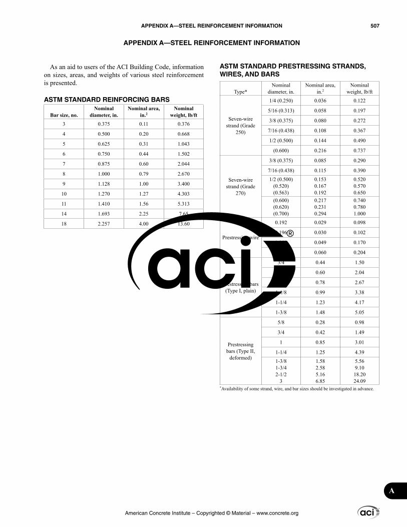
As an aid to users of the ACI Building Code, information on sizes, areas, and weights of various steel reinforcement is presented.
ASTM STANDARD REINFORCING BARS
Bar size, no.Nominal
diameter, in.Nominal area,
in.2Nominal
weight, lb/ft
3 0.375 0.11 0.376
4 0.500 0.20 0.668
5 0.625 0.31 1.043
6 0.750 0.44 1.502
7 0.875 0.60 2.044
8 1.000 0.79 2.670
9 1.128 1.00 3.400
10 1.270 1.27 4.303
11 1.410 1.56 5.313
14 1.693 2.25 7.65
18 2.257 4.00 13.60
ASTM STANDARD PRESTRESSING STRANDS, WIRES, AND BARS
Type*Nominal
diameter, in.Nominal area,
in.2Nominal
weight, lb/ft
Seven-wire strand (Grade
250)
1/4 (0.250) 0.036 0.122
5/16 (0.313) 0.058 0.197
3/8 (0.375) 0.080 0.272
7/16 (0.438) 0.108 0.367
1/2 (0.500) 0.144 0.490
(0.600) 0.216 0.737
Seven-wire strand (Grade
270)
3/8 (0.375) 0.085 0.290
7/16 (0.438) 0.115 0.390
1/2 (0.500)(0.520)(0.563)
0.1530.1670.192
0.5200.5700.650
(0.600)(0.620)(0.700)
0.2170.2310.294
0.7400.7801.000
Prestressing wire
0.192 0.029 0.098
0.196 0.030 0.102
0.250 0.049 0.170
0.276 0.060 0.204
Prestressing bars (Type I, plain)
3/4 0.44 1.50
7/8 0.60 2.04
1 0.78 2.67
1-1/8 0.99 3.38
1-1/4 1.23 4.17
1-3/8 1.48 5.05
Prestressing bars (Type II,
deformed)
5/8 0.28 0.98
3/4 0.42 1.49
1 0.85 3.01
1-1/4 1.25 4.39
1-3/81-3/42-1/2
3
1.582.585.166.85
5.569.1018.2024.09
*Availability of some strand, wire, and bar sizes should be investigated in advance.
APPENDIX A—STEEL REINFORCEMENT INFORMATION
American Concrete Institute – Copyrighted © Material – www.concrete.org
APPENDIX A—STEEL REINFORCEMENT INFORMATION 507
A
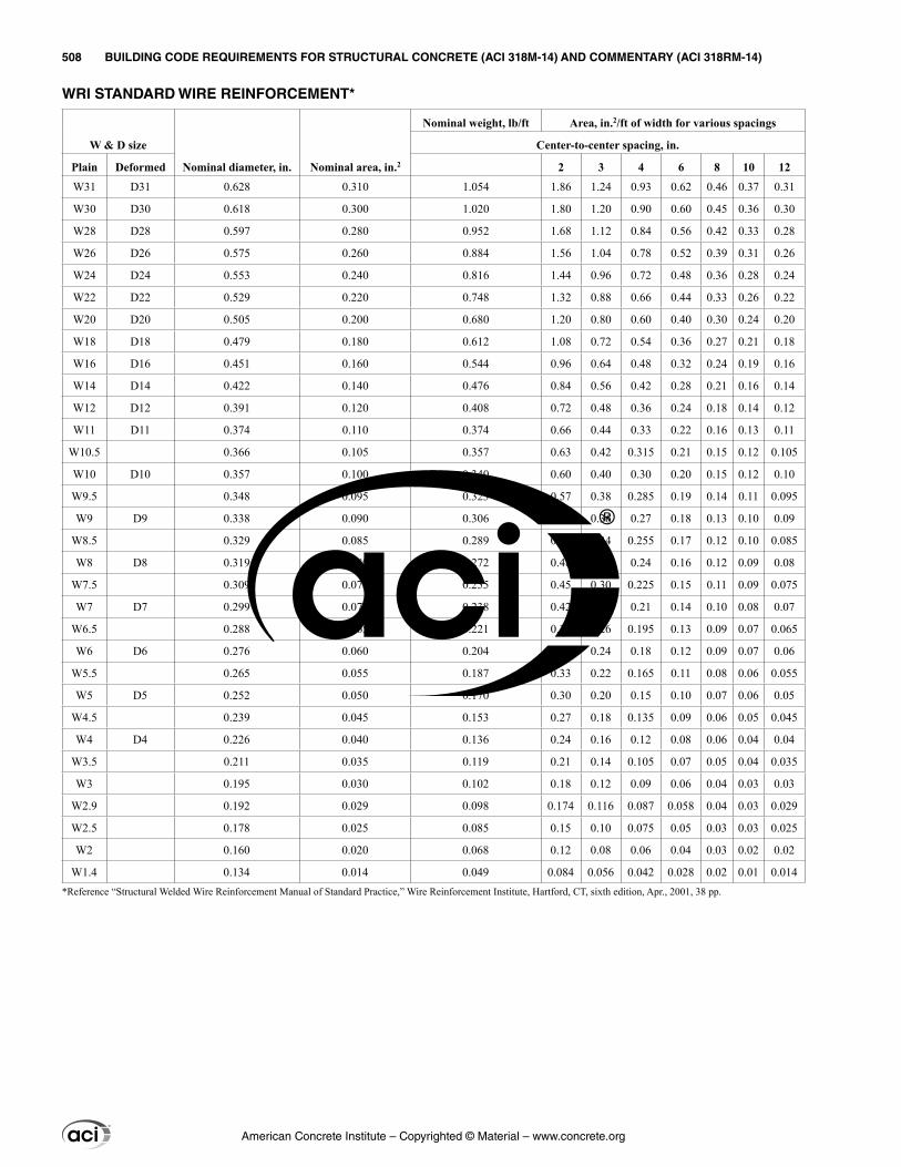
WRI STANDARD WIRE REINFORCEMENT*
W & D size
Nominal diameter, in. Nominal area, in.2
Nominal weight, lb/ft Area, in.2/ft of width for various spacings
Center-to-center spacing, in.
Plain Deformed 2 3 4 6 8 10 12
W31 D31 0.628 0.310 1.054 1.86 1.24 0.93 0.62 0.46 0.37 0.31
W30 D30 0.618 0.300 1.020 1.80 1.20 0.90 0.60 0.45 0.36 0.30
W28 D28 0.597 0.280 0.952 1.68 1.12 0.84 0.56 0.42 0.33 0.28
W26 D26 0.575 0.260 0.884 1.56 1.04 0.78 0.52 0.39 0.31 0.26
W24 D24 0.553 0.240 0.816 1.44 0.96 0.72 0.48 0.36 0.28 0.24
W22 D22 0.529 0.220 0.748 1.32 0.88 0.66 0.44 0.33 0.26 0.22
W20 D20 0.505 0.200 0.680 1.20 0.80 0.60 0.40 0.30 0.24 0.20
W18 D18 0.479 0.180 0.612 1.08 0.72 0.54 0.36 0.27 0.21 0.18
W16 D16 0.451 0.160 0.544 0.96 0.64 0.48 0.32 0.24 0.19 0.16
W14 D14 0.422 0.140 0.476 0.84 0.56 0.42 0.28 0.21 0.16 0.14
W12 D12 0.391 0.120 0.408 0.72 0.48 0.36 0.24 0.18 0.14 0.12
W11 D11 0.374 0.110 0.374 0.66 0.44 0.33 0.22 0.16 0.13 0.11
W10.5 0.366 0.105 0.357 0.63 0.42 0.315 0.21 0.15 0.12 0.105
W10 D10 0.357 0.100 0.340 0.60 0.40 0.30 0.20 0.15 0.12 0.10
W9.5 0.348 0.095 0.323 0.57 0.38 0.285 0.19 0.14 0.11 0.095
W9 D9 0.338 0.090 0.306 0.54 0.36 0.27 0.18 0.13 0.10 0.09
W8.5 0.329 0.085 0.289 0.51 0.34 0.255 0.17 0.12 0.10 0.085
W8 D8 0.319 0.080 0.272 0.48 0.32 0.24 0.16 0.12 0.09 0.08
W7.5 0.309 0.075 0.255 0.45 0.30 0.225 0.15 0.11 0.09 0.075
W7 D7 0.299 0.070 0.238 0.42 0.28 0.21 0.14 0.10 0.08 0.07
W6.5 0.288 0.065 0.221 0.39 0.26 0.195 0.13 0.09 0.07 0.065
W6 D6 0.276 0.060 0.204 0.36 0.24 0.18 0.12 0.09 0.07 0.06
W5.5 0.265 0.055 0.187 0.33 0.22 0.165 0.11 0.08 0.06 0.055
W5 D5 0.252 0.050 0.170 0.30 0.20 0.15 0.10 0.07 0.06 0.05
W4.5 0.239 0.045 0.153 0.27 0.18 0.135 0.09 0.06 0.05 0.045
W4 D4 0.226 0.040 0.136 0.24 0.16 0.12 0.08 0.06 0.04 0.04
W3.5 0.211 0.035 0.119 0.21 0.14 0.105 0.07 0.05 0.04 0.035
W3 0.195 0.030 0.102 0.18 0.12 0.09 0.06 0.04 0.03 0.03
W2.9 0.192 0.029 0.098 0.174 0.116 0.087 0.058 0.04 0.03 0.029
W2.5 0.178 0.025 0.085 0.15 0.10 0.075 0.05 0.03 0.03 0.025
W2 0.160 0.020 0.068 0.12 0.08 0.06 0.04 0.03 0.02 0.02
W1.4 0.134 0.014 0.049 0.084 0.056 0.042 0.028 0.02 0.01 0.014*Reference “Structural Welded Wire Reinforcement Manual of Standard Practice,” Wire Reinforcement Institute, Hartford, CT, sixth edition, Apr., 2001, 38 pp.
American Concrete Institute – Copyrighted © Material – www.concrete.org
508 BUILDING CODE REQUIREMENTS FOR STRUCTURAL CONCRETE (ACI 318M-14) AND COMMENTARY (ACI 318RM-14)
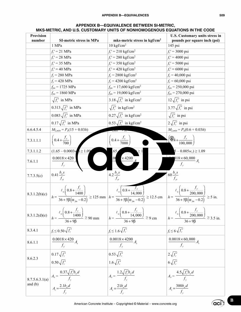
American Concrete Institute – Copyrighted © Material – www.concrete.org
APPENDIX B—EQUIVALENCES 509
B
APPENDIX B—EQUIVALENCE BETWEEN SI-METRIC, MKS-METRIC, AND U.S. CUSTOMARY UNITS OF NONHOMOGENOUS EQUATIONS IN THE CODE
Provision number SI-metric stress in MPa mks-metric stress in kgf/cm2
U.S. Customary units stress in pounds per square inch (psi)
1 MPa 10 kgf/cm2 145 psifc′ = 21 MPa fc′ = 210 kgf/cm2 fc′ = 3000 psifc′ = 28 MPa fc′ = 280 kgf/cm2 fc′ = 4000 psifc′ = 35 MPa fc′ = 350 kgf/cm2 fc′ = 5000 psifc′ = 40 MPa fc′ = 420 kgf/cm2 fc′ = 6000 psify = 280 MPa fy = 2800 kgf/cm2 fy = 40,000 psify = 420 MPa fy = 4200 kgf/cm2 fy = 60,000 psifpu = 1725 MPa fpu = 17,600 kgf/cm2 fpu = 250,000 psifpu = 1860 MPa fpu = 19,000 kgf/cm2 fpu = 270,000 psi
cf ′ in MPa 3.18 cf ′ in kgf/cm2 12 cf ′ in psi
0.313 cf ′ in MPa cf ′ in kgf/cm2 3.77 cf ′ in psi
0.083 cf ′ in MPa 0.27 cf ′ in kgf/cm2cf ′ in psi
0.17 cf ′ in MPa 0.53 cf ′ in kgf/cm2 2 cf ′ in psi
6.6.4.5.4 M2,min = Pu(15 + 0.03h) M2,min = Pu(1.5 + 0.03h) M2,min = Pu(0.6 + 0.03h)
7.3.1.1.1 0.4 700
yf +
0.4 7000
yf +
0.4 100,000
yf +
7.3.1.1.2 (1.65 – 0.0003wc) ≥ 1.09 (1.65 – 0.0003wc) ≥ 1.09 (1.65 – 0.005wc) ≥ 1.09
7.6.1.10.0018 420×
sy
Af
0.0018 4200×s
y
Af
0.0018 60,000×s
y
Af
7.7.3.5(c) 0.41 w
yt
b sf
4.2 w
yt
b sf
60 w
yt
b sf
8.3.1.2(b)(c)h = ( )
0.8 1400
36 5 0.2
yn
fm
f +
+ β −α
≥ 125 mm h = ( )0.8
14,000
36 5 0.2
yn
fm
f +
α
+ β −
≥ 12.5 cm h = ( )
0.8 200,000
36 5 0.2
yn
fm
f +
α
+ β −
≥ 5 in.
8.3.1.2(d)(e)h =
0.8 1400
36 9
yn
f + + β
≥ 90 mm h = 0.8
14,00036 9
yn
f + + β
≥ 9 cm h = 0.8
200,00036 9
yn
f +
+ β
≥ 3.5 in.
8.3.4.1 ft ≤ 0.50 cf ′ ft ≤ 1.6 cf ′ ft ≤ 6 cf ′
8.6.1.10.0018 420×
sy
Af
0.0018 4200×s
y
Af
0.0018 60,000×s
y
Af
8.6.2.30.17 cf ′
0.50 cf ′
0.53 cf ′
1.6 cf ′
2 cf ′
6 cf ′
8.7.5.6.3.1(a) and (b)
As =
0.37 c w
y
f b df
′
2.1 = ws
y
b dAf
As =
1.2 c w
y
f b df
′
21 = ws
y
b dAf
As =
4.5 c w
y
f b df
′
300 = ws
y
b dAf
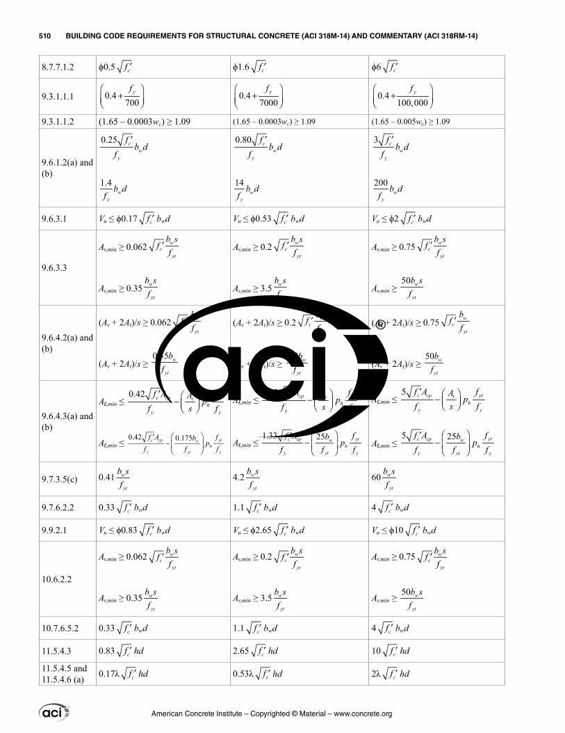
American Concrete Institute – Copyrighted © Material – www.concrete.org
510 BUILDING CODE REQUIREMENTS FOR STRUCTURAL CONCRETE (ACI 318M-14) AND COMMENTARY (ACI 318RM-14)
8.7.7.1.2 ϕ0.5 cf ′ ϕ1.6 cf ′ ϕ6 cf ′
9.3.1.1.1 0.4 700
yf +
0.4 7000
yf +
0.4 100,000
yf +
9.3.1.1.2 (1.65 – 0.0003wc) ≥ 1.09 (1.65 – 0.0003wc) ≥ 1.09 (1.65 – 0.005wc) ≥ 1.09
9.6.1.2(a) and (b)
0.25 cw
y
fb d
f′
1.4w
y
b df
0.80 cw
y
fb d
f′
14w
y
b df
3 cw
y
fb d
f′
200w
y
b df
9.6.3.1 Vu ≤ ϕ0.17 cf ′ bwd Vu ≤ ϕ0.53 cf ′ bwd Vu ≤ ϕ2 cf ′ bwd
9.6.3.3
Av,min ≥ 0.062 wc
yt
b sf
f′
Av,min ≥ 0.35 w
yt
b sf
Av,min ≥ 0.2 wc
yt
b sf
f′
Av,min ≥ 3.5 w
yt
b sf
Av,min ≥ 0.75 wc
yt
b sf
f′
Av,min ≥ 50 w
yt
b sf
9.6.4.2(a) and (b)
(Av + 2At)/s ≥ 0.062 wc
yt
bf
f′
(Av + 2At)/s ≥ 0.35 w
yt
bf
(Av + 2At)/s ≥ 0.2 wc
yt
bf
f′
(Av + 2At)/s ≥ 3.5 w
yt
bf
(Av + 2At)/s ≥ 0.75 wc
yt
bf
f′
(Av + 2At)/s ≥ 50 w
yt
bf
9.6.4.3(a) and (b)
Al,min ≤ 0.42 cp ytt
hc
y y
A fAp
f sf
f
′−
Al,min ≤
0.42 0.175cp ytwh
y yt y
c A fbp
f ff
f
−
′
Al,min ≤ 1.33 cp ytt
hc
y y
A fAp
f sf
f
′−
Al,min ≤ 1.33 25cp ytw
hy yt y
c A fbp
ff
f f
− ′
Al,min ≤ 5 cp ytt
hy
c
y
A fAp
f s ff −
′
Al,min ≤ 5 25cp ytw
hy yt
c
y
A fbp
f fff
−
′
9.7.3.5(c) 0.41 w
yt
b sf
4.2 w
yt
b sf
60 w
yt
b sf
9.7.6.2.2 0.33 cf ′ bwd 1.1 cf ′ bwd 4 cf ′ bwd
9.9.2.1 Vu ≤ ϕ0.83 cf ′ bwd Vu ≤ ϕ2.65 cf ′ bwd Vu ≤ ϕ10 cf ′ bwd
10.6.2.2
Av,min ≥ 0.062 w
tc
y
fb sf
′
Av,min ≥ 0.35 w
yt
b sf
Av,min ≥ 0.2 w
tc
y
fb sf
′
Av,min ≥ 3.5 w
yt
b sf
Av,min ≥ 0.75 w
tc
y
fb sf
′
Av,min ≥ 50 w
yt
b sf
10.7.6.5.2 0.33 cf ′ bwd 1.1 cf ′ bwd 4 cf ′ bwd
11.5.4.3 0.83 cf ′ hd 2.65 cf ′ hd 10 cf ′ hd
11.5.4.5 and 11.5.4.6 (a) 0.17λ cf ′ hd 0.53λ cf ′ hd 2λ cf ′ hd
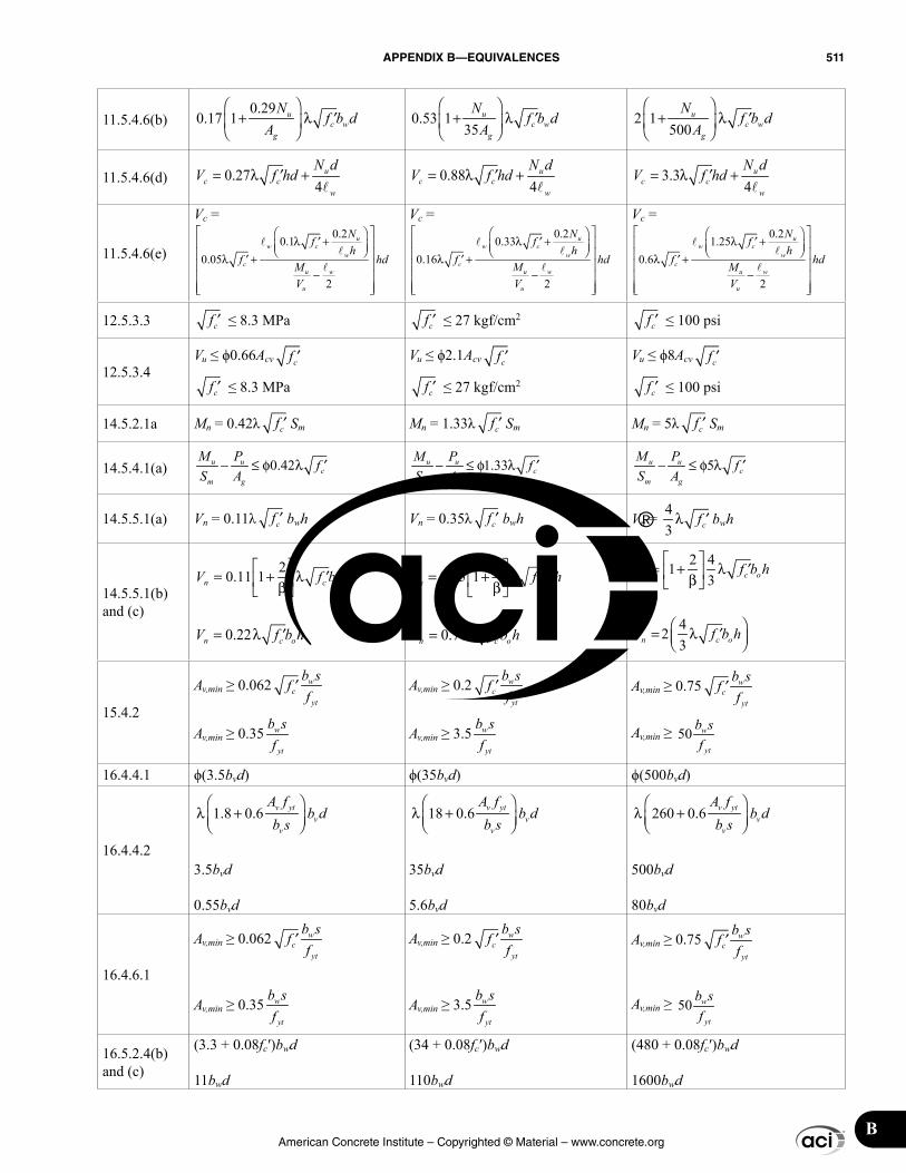
American Concrete Institute – Copyrighted © Material – www.concrete.org
APPENDIX B—EQUIVALENCES 511
B
11.5.4.6(b)0.29
0.17 1 uc w
g
Nf b d
A
+ λ ′
0.53 1 35
uc w
g
Nf b d
A
+ λ ′
2 1 500
uc w
g
Nf b d
A
+ λ ′
11.5.4.6(d) 0.274
uc c
w
N dV f hd= λ +′
0.884
uc c
w
N dV f hd= λ +′
3.34
uc c
w
N dV f hd= λ +′
11.5.4.6(e)
Vc = 0.2
0.10.05
2
uw
w
u
cu
c
w
fNh
hd
V
f M
λ + λ +
−
′′
Vc = 0.2
0.330.16
2
uw
w
u w
u
c
c
Nh
hdMV
ff
λ + λ +
−
′′
Vc = 0.2
1.250.6
2
uw
w
u
cu
c
w
fNh
hd
V
f M
λ + λ +
−
′′
12.5.3.3 cf ′ ≤ 8.3 MPa cf ′ ≤ 27 kgf/cm2cf ′ ≤ 100 psi
12.5.3.4Vu ≤ ϕ0.66Acv cf ′
cf ′ ≤ 8.3 MPa
Vu ≤ ϕ2.1Acv cf ′
cf ′ ≤ 27 kgf/cm2
Vu ≤ ϕ8Acv cf ′
cf ′ ≤ 100 psi
14.5.2.1a Mn = 0.42λ cf ′ Sm Mn = 1.33λ cf ′ Sm Mn = 5λ cf ′ Sm
14.5.4.1(a) 0.42− ≤ φ ′λu u
m gc
M PS A
f 1.33− ≤ φ ′λu u
m gc
M PS A
f 5− ′≤ φ λu u
m gc
M PS A
f
14.5.5.1(a) Vn = 0.11λ cf ′ bwh Vn = 0.35λ cf ′ bwh Vn = 4 3 cfλ ′ bwh
14.5.5.1(b) and (c)
20.11 1 ocnV b hf
= + λ β′
0.22 cn ofV b h′= λ
V b hfn oc= +
′0 35 1 2.
βλ
0.71 cn ofV b h′= λ
2 413n ocfV b h
= + λ β
′
4 23 cn oV b hf = λ ′
15.4.2
Av,min ≥ 0.062 w
tc
y
fb sf
′
Av,min ≥ 0.35 w
yt
b sf
Av,min ≥ 0.2 w
tc
y
fb sf
′
Av,min ≥ 3.5 w
yt
b sf
Av,min ≥ 0.75 w
tc
y
fb sf
′
Av,min ≥ 50 w
yt
b sf
16.4.4.1 ϕ(3.5bvd) ϕ(35bvd) ϕ(500bvd)
16.4.4.2
1.8 0.6 v ytv
v
A fb d
b s
λ +
3.5bvd
0.55bvd
18 0.6 v ytv
v
A fb d
b s
λ +
35bvd
5.6bvd
260 0.6 v ytv
v
A fb d
b s
λ +
500bvd
80bvd
16.4.6.1
Av,min ≥ 0.062 w
tc
y
fb sf
′
Av,min ≥ 0.35 w
yt
b sf
Av,min ≥ 0.2 w
tc
y
fb sf
′
Av,min ≥ 3.5 w
yt
b sf
Av,min ≥ 0.75 w
tc
y
fb sf
′
Av,min ≥ 50 w
yt
b sf
16.5.2.4(b) and (c)
(3.3 + 0.08fc′)bwd
11bwd
(34 + 0.08fc′)bwd
110bwd
(480 + 0.08fc′)bwd
1600bwd
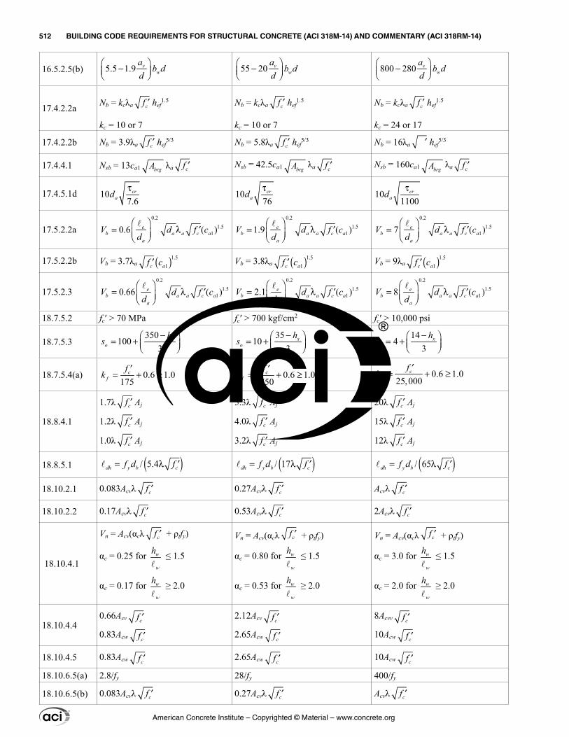
American Concrete Institute – Copyrighted © Material – www.concrete.org
512 BUILDING CODE REQUIREMENTS FOR STRUCTURAL CONCRETE (ACI 318M-14) AND COMMENTARY (ACI 318RM-14)
16.5.2.5(b) 5.5 1.9 vw
ab d
d −
55 20 vw
ab d
d −
800 280 vw
ab d
d −
17.4.2.2a Nb = kcλa cf ′ hef1.5
kc = 10 or 7
Nb = kcλa cf ′ hef1.5
kc = 10 or 7
Nb = kcλa cf ′ hef1.5
kc = 24 or 17
17.4.2.2b Nb = 3.9λa cf ′ hef5/3 Nb = 5.8λa cf ′ hef
5/3 Nb = 16λa ′ hef5/3
17.4.4.1 Nsb = 13ca1 brgA λa cf ′ Nsb = 42.5ca1 brgA λa cf ′ Nsb = 160ca1 brgA λa cf ′
17.4.5.1d 10 7.6
crad
τ10
76cr
adτ
10 1100
crad
τ
17.5.2.2a0.2
1.510.6 ( )e
b a a c aa
V d f cd
= λ ′
0.21.5
11.9 ( )eb a a c a
a
V d f cd
= λ ′
0.21.5
17 ( )eb a a c a
a
V d f cd
= λ ′
17.5.2.2b Vb = 3.7λa ( )1.51acf c′ Vb = 3.8λa ( )1.5
1acf c′ Vb = 9λa ( )1.51acf c′
17.5.2.30.2
1.510.66 ( )e
b a a c aa
V d f cd
= λ ′
0.21.5
12.1 ( )eb a a c a
a
V d f cd
= λ ′
0.21.5
18 ( )eb a a c a
a
V d f cd
= λ ′
18.7.5.2 fc′ > 70 MPa fc′ > 700 kgf/cm2 fc′ > 10,000 psi
18.7.5.3350
1003
xo
hs
− = + 35
103
xo
hs
− = + 14
43
xo
hs
− = +
18.7.5.4(a) 0.6 1.0175f
ckf
+ ≥′
= 0.6 1.01750f
ckf
+ ≥′
= 0.6 1.025,000
cf
fk ≥
′= +
18.8.4.1
1.7λ cf ′ Aj
1.2λ cf ′ Aj
1.0λ cf ′ Aj
5.3λ cf ′ Aj
4.0λ cf ′ Aj
3.2λ cf ′ Aj
20λ cf ′ Aj
15λ cf ′ Aj
12λ cf ′ Aj
18.8.5.1 ( )/ 5.4dh y b cff d= ′λ ( )/ 17 ′= λdh y b cf d f ( )/ 65dh y b cf d f= λ ′
18.10.2.1 0.083Acvλ cf ′ 0.27Acvλ cf ′ Acvλ cf ′
18.10.2.2 0.17Acvλ cf ′ 0.53Acvλ cf ′ 2Acvλ cf ′
18.10.4.1
Vn = Acv(αcλ cf ′ + ρtfy)
αc = 0.25 for w
w
h
≤ 1.5
αc = 0.17 for w
w
h
≥ 2.0
Vn = Acv(αcλ cf ′ + ρtfy)
αc = 0.80 for w
w
h
≤ 1.5
αc = 0.53 for w
w
h
≥ 2.0
Vn = Acv(αcλ cf ′ + ρtfy)
αc = 3.0 for w
w
h
≤ 1.5
αc = 2.0 for w
w
h
≥ 2.0
18.10.4.40.66Acv cf ′
0.83Acw cf ′
2.12Acv cf ′
2.65Acw cf ′
8Acvv cf ′
10Acw cf ′
18.10.4.5 0.83Acw cf ′ 2.65Acw cf ′ 10Acw cf ′
18.10.6.5(a) 2.8/fy 28/fy 400/fy
18.10.6.5(b) 0.083Acvλ cf ′ 0.27Acvλ cf ′ Acvλ cf ′
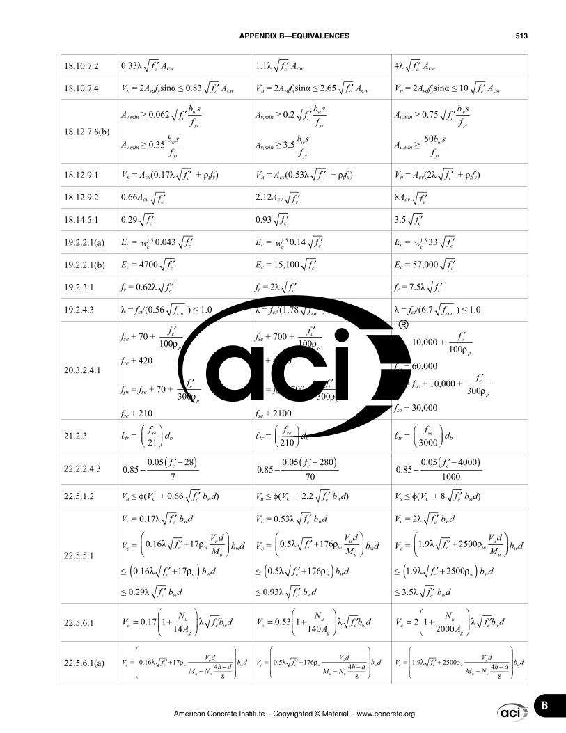
American Concrete Institute – Copyrighted © Material – www.concrete.org
APPENDIX B—EQUIVALENCES 513
B
18.10.7.2 0.33λ cf ′ Acw 1.1λ cf ′ Acw 4λ cf ′ Acw
18.10.7.4 Vn = 2Avdfysinα ≤ 0.83 cf ′ Acw Vn = 2Avdfysinα ≤ 2.65 cf ′ Acw Vn = 2Avdfysinα ≤ 10 cf ′ Acw
18.12.7.6(b)
Av,min ≥ 0.062 w
tc
y
fb sf
′
Av,min ≥ 0.35 w
yt
b sf
Av,min ≥ 0.2 w
tc
y
fb sf
′
Av,min ≥ 3.5 w
yt
b sf
Av,min ≥ 0.75 w
tc
y
fb sf
′
Av,min ≥ 50 w
yt
b sf
18.12.9.1 Vn = Acv(0.17λ cf ′ + ρtfy) Vn = Acv(0.53λ cf ′ + ρtfy) Vn = Acv(2λ cf ′ + ρtfy)
18.12.9.2 0.66Acv cf ′ 2.12Acv cf ′ 8Acv cf ′
18.14.5.1 0.29 cf ′ 0.93 cf ′ 3.5 cf ′
19.2.2.1(a) Ec = 1.5cw 0.043 cf ′ Ec = 1.5
cw 0.14 cf ′ Ec = 1.5cw 33 cf ′
19.2.2.1(b) Ec = 4700 cf ′ Ec = 15,100 cf ′ Ec = 57,000 cf ′
19.2.3.1 fr = 0.62λ cf ′ fr = 2λ cf ′ fr = 7.5λ cf ′
19.2.4.3 λ = fct/(0.56 cmf ) ≤ 1.0 λ = fct/(1.78 cmf ) ≤ 1.0 λ = fct/(6.7 cmf ) ≤ 1.0
20.3.2.4.1
fse + 70 + 100 p
cf ′ρ
fse + 420
fps = fse + 70 + 300 p
cf ′ρ
fse + 210
fse + 700 + 100 p
cf ′ρ
fse + 4200
fps = fse + 700 + 300 p
cf ′ρ
fse + 2100
fse + 10,000 + 100 p
cf ′ρ
fse + 60,000
fps = fse + 10,000 + 300 p
cf ′ρ
fse + 30,000
21.2.3 ℓtr = 21
sef
db ℓtr = 210
sef
db ℓtr = 3000
sef
db
22.2.2.4.3 ( )0.05 280.85
7cf −′
− ( )0.05 2800.85
70cf −′
− ( )0.05 40000.85
1000cf −′
−
22.5.1.2 Vu ≤ ϕ(Vc + 0.66 cf ′ bwd) Vu ≤ ϕ(Vc + 2.2 cf ′ bwd) Vu ≤ ϕ(Vc + 8 cf ′ bwd)
22.5.5.1
Vc = 0.17λ cf ′ bwd
Vc = 0.16 1 7cu
wu
fV dM
λ + ρ
′ bwd
≤ ( )0.16 1 7c wf +′λ ρ bwd
≤ 0.29λ cf ′ bwd
Vc = 0.53λ cf ′ bwd
Vc = 0.5 1 76 uwc
u
VM
fd
λ + ρ′ bwd
≤ ( )0.5 1 76 wcfλ + ρ′ bwd
≤ 0.93λ cf ′ bwd
Vc = 2λ cf ′ bwd
Vc = 1.9 2500cu
wu
fV dM
λ + ρ
′ bwd
≤ ( )1.9 2500c wfλ + ρ′ bwd
≤ 3.5λ cf ′ bwd
22.5.6.1 0.17 1 14
uc c w
g
NV f b d
A
= + λ ′
0.53 1 140
uc c w
g
NV f b d
A
= + λ ′
2 1 2000
uc c w
g
NV f b d
A
= + λ ′
22.5.6.1(a) 0.16 17 48
uc c w w
u u
V dV f b dh dM N
= λ + ρ′ − −
0.5 176 48
uc c w w
u u
V dV f b dh dM N
= λ + ρ′ − −
1.9 2500 48
uc c w w
u u
V dV f b dh dM N
= λ + ρ′ − −
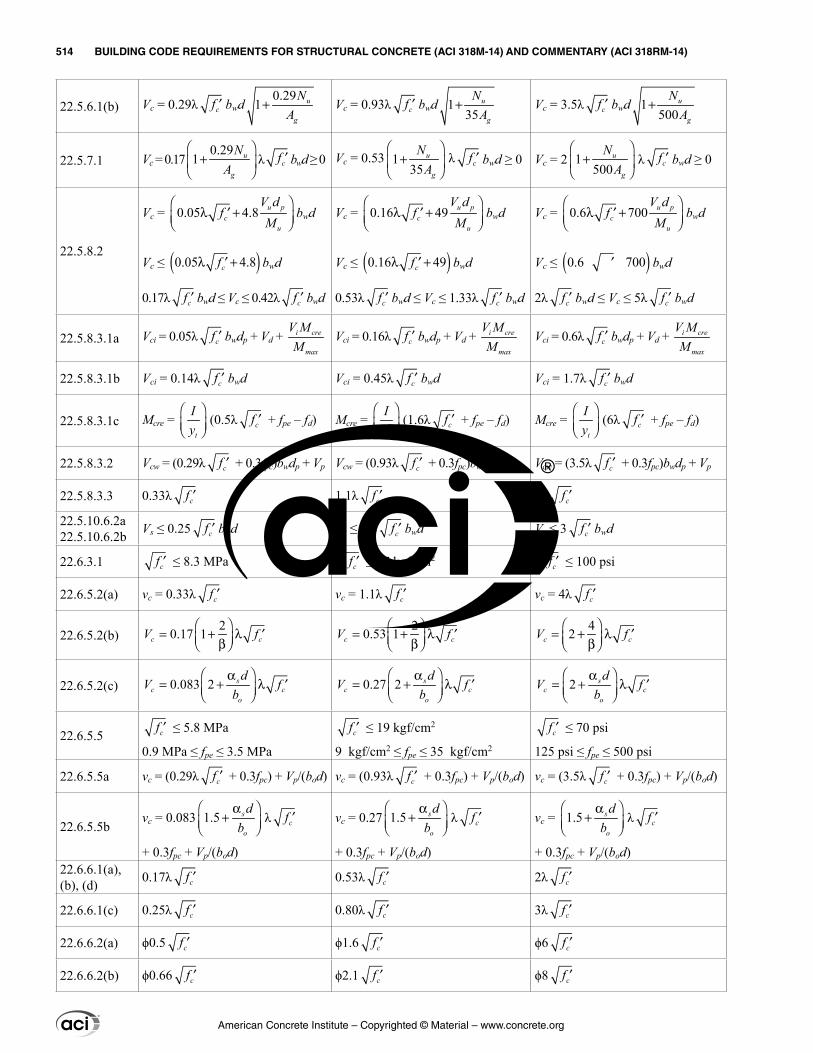
American Concrete Institute – Copyrighted © Material – www.concrete.org
514 BUILDING CODE REQUIREMENTS FOR STRUCTURAL CONCRETE (ACI 318M-14) AND COMMENTARY (ACI 318RM-14)
22.5.6.1(b) Vc = 0.29λ cf ′ bwd0.29
1 u
g
NA
+ Vc = 0.93λ cf ′ bwd 1 35
u
g
NA
+ Vc = 3.5λ cf ′ bwd 1 500
u
g
NA
+
22.5.7.1 Vc = 0.170.29
1 u
g
NA
+
λ cf ′ bwd ≥ 0 Vc = 0.53 1
35u
g
NA
+
λ cf ′ bwd ≥ 0 Vc = 2 1
500u
g
NA
+
λ cf ′ bwd ≥ 0
22.5.8.2
Vc = 0.05 4.8 u pc
u
V dM
f
λ + ′ bwd
Vc ≤ ( )0.05 4.8cf +′λ bwd
0.17λ cf ′ bwd ≤ Vc ≤ 0.42λ cf ′ bwd
Vc = 0.16 49 u pc
u
VM
fd
′
λ + bwd
Vc ≤ ( )0.16 49cf +′λ bwd
0.53λ cf ′ bwd ≤ Vc ≤ 1.33λ cf ′ bwd
Vc = 0.6 700 uc
p
u
VM
fd
′
λ + bwd
Vc ≤ ( )0.6 700′ bwd
2λ cf ′ bwd ≤ Vc ≤ 5λ cf ′ bwd
22.5.8.3.1a Vci = 0.05λ cf ′ bwdp + Vd + i cre
max
V MM
Vci = 0.16λ cf ′ bwdp + Vd + i cre
max
V MM
Vci = 0.6λ cf ′ bwdp + Vd + i cre
max
V MM
22.5.8.3.1b Vci = 0.14λ cf ′ bwd Vci = 0.45λ cf ′ bwd Vci = 1.7λ cf ′ bwd
22.5.8.3.1c Mcre = t
Iy
(0.5λ cf ′ + fpe – fd) Mcre = t
Iy
(1.6λ cf ′ + fpe – fd) Mcre = t
Iy
(6λ cf ′ + fpe – fd)
22.5.8.3.2 Vcw = (0.29λ cf ′ + 0.3fpc)bwdp + Vp Vcw = (0.93λ cf ′ + 0.3fpc)bwdp + Vp Vcw = (3.5λ cf ′ + 0.3fpc)bwdp + Vp
22.5.8.3.3 0.33λ cf ′ 1.1λ cf ′ 4λ cf ′
22.5.10.6.2a 22.5.10.6.2b Vs ≤ 0.25 cf ′ bwd Vs ≤ 0.8 cf ′ bwd Vs ≤ 3 cf ′ bwd
22.6.3.1 cf ′ ≤ 8.3 MPa cf ′ ≤ 27 kgf/cm2cf ′ ≤ 100 psi
22.6.5.2(a) vc = 0.33λ cf ′ vc = 1.1λ cf ′ vc = 4λ cf ′
22.6.5.2(b)20.17 1c cV f
= + λ ′ β
20.53 1c cV f
= + λ ′ β42
= + λ ′ β c cV f
22.6.5.2(c) 0.083 2c cs
o
dV f
b
= + λ ′ α
0.27 2c c
s
o
db
V f
= + λ ′ α
2 sc c
o
V fd
b
= + λ ′ α
22.6.5.5 cf ′ ≤ 5.8 MPa
0.9 MPa ≤ fpe ≤ 3.5 MPacf ′ ≤ 19 kgf/cm2
9 kgf/cm2 ≤ fpe ≤ 35 kgf/cm2
cf ′ ≤ 70 psi
125 psi ≤ fpe ≤ 500 psi
22.6.5.5a vc = (0.29λ cf ′ + 0.3fpc) + Vp/(bod) vc = (0.93λ cf ′ + 0.3fpc) + Vp/(bod) vc = (3.5λ cf ′ + 0.3fpc) + Vp/(bod)
22.6.5.5bvc = 0.083 1.5 s
o
db
α+
λ cf ′
+ 0.3fpc + Vp/(bod)
vc = 0.27 1.5 s
o
db
α+
λ cf ′
+ 0.3fpc + Vp/(bod)
vc = 1.5 s
o
db
α+
λ cf ′
+ 0.3fpc + Vp/(bod)22.6.6.1(a), (b), (d) 0.17λ cf ′ 0.53λ cf ′ 2λ cf ′
22.6.6.1(c) 0.25λ cf ′ 0.80λ cf ′ 3λ cf ′
22.6.6.2(a) ϕ0.5 cf ′ ϕ1.6 cf ′ ϕ6 cf ′
22.6.6.2(b) ϕ0.66 cf ′ ϕ2.1 cf ′ ϕ8 cf ′
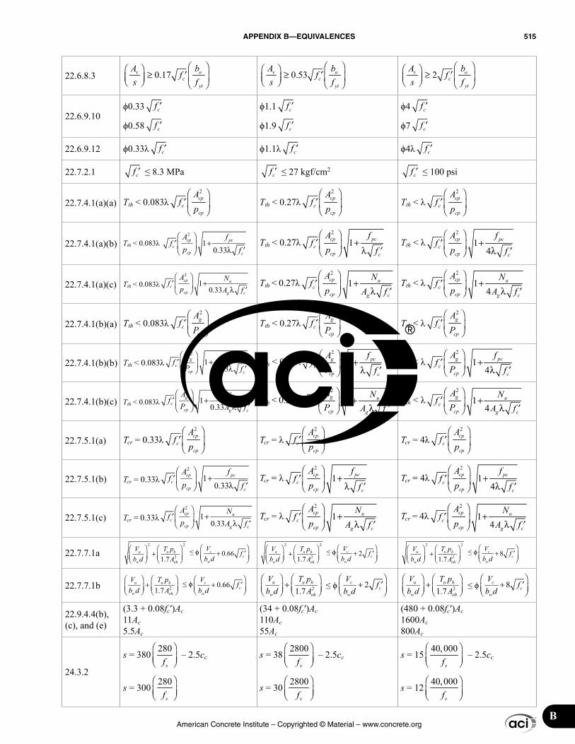
American Concrete Institute – Copyrighted © Material – www.concrete.org
APPENDIX B—EQUIVALENCES 515
B
22.6.8.3 0.17v oc
yt
A bf
s f ≥ ′
0.53v oc
yt
A bf
s f ≥ ′
2v oc
yt
A bf
s f ≥ ′
22.6.9.10ϕ0.33 cf ′
ϕ0.58 cf ′
ϕ1.1 cf ′
ϕ1.9 cf ′
ϕ4 cf ′
ϕ7 cf ′
22.6.9.12 ϕ0.33λ cf ′ ϕ1.1λ cf ′ ϕ4λ cf ′
22.7.2.1 cf ′ ≤ 8.3 MPa cf ′ ≤ 27 kgf/cm2cf ′ ≤ 100 psi
22.7.4.1(a)(a) Tth < 0.083λ2cp
cpcf
Ap
′
Tth < 0.27λ2cp
cpcf
Ap
′
Tth < λ2cp
cpcf
Ap
′
22.7.4.1(a)(b) Tth < 0.083λ 2
1 0.33c
c
cp pc
cp fpf
A f + ′
λ ′ Tth < 0.27λ
2
1 cp pc
cc
p c
ff
A fp
+
′
λ ′
Tth < λ2
1 4
cp pc
cpc
c
f
f
Ap
f
+
′λ ′
22.7.4.1(a)(c) Tth < 0.083λ2
1 0.33
cp u
cpc
cg
A Np A
ff
+ ′
λ ′ Tth < 0.27λ
2
1 cp u
cp gc
c
A Np A
ff
+
′
λ ′
Tth < λ2
1 4
cp u
cpc
cg
A
fp Af
N + λ
′′
22.7.4.1(b)(a) Tth < 0.083λ2g
ccp
Af
P
′
Tth < 0.27λ2g
ccp
Af
P
′
Tth < λ2g
ccp
Af
P
′
22.7.4.1(b)(b) Tth < 0.083λ2
1 0.33
+
′
′λg pc
c cpcf
A ffP
Tth < 0.27λ2
1
′+ λ
′cg pc
p cc
fA fP f
Tth < λ2
1 4
+ λ
′′
g pc
c c
c
p
A fP
ff
22.7.4.1(b)(c) Tth < 0.083λ2
1 0.33
+ ′λ
′
g u
c gc
cp
A NP A
ff
Tth < 0.27λ2
1
+ λ ′
′g
cc gc
u
p
A NfA fP
Tth < λ2
1 4
+ λ
′′
g u
c cp gc
A NP A
ff
22.7.5.1(a) Tcr = 0.33λ2cp
cpcf
Ap
′
Tcr = λ2cp
cpcf
Ap
′
Tcr = 4λ2cp
cpcf
Ap
′
22.7.5.1(b) Tcr = 0.33λ2
1 0.33c
c
cp pc
cp fpf
A f + ′
λ ′ Tcr = λ
2
1 cp pc
cc
p c
ff
A fp
+
′
λ ′
Tcr = 4λ2
1 4
cp pc
cpc
c
f
f
Ap
f
+
′λ ′
22.7.5.1(c) Tcr = 0.33λ2
1 0.33
cp u
cpc
cg
A Np A
ff
+ ′
λ ′ Tcr = λ
2
1 cp u
cp gc
c
A Np A
ff
+
′
λ ′
Tcr = 4λ2
1 4
cp u
cpc
cg
A
fp Af
N + λ
′′
22.7.7.1a22
21.7u u h
w oh
V T pb d A
+
≤ ϕ 0.66cc
w
fVb d
+ ′
22
21.7u u h
w oh
V T pb d A
+
≤ ϕ 2cc
w
fVb d
′
+
22
21.7u u h
w oh
V T pb d A
+
≤ ϕ 8cc
w
fVb d
′
+
22.7.7.1b 21.7u u h
w oh
V T pb d A
+
≤ ϕ 0.66cc
w
fVb d
+ ′
21.7
u u h
w oh
V T pb d A
+
≤ ϕ 2cc
w
fVb d
′
+ 21.7u u h
w oh
V T pb d A
+
≤ ϕ 8cc
w
fVb d
′
+
22.9.4.4(b), (c), and (e)
(3.3 + 0.08fc′)Ac11Ac5.5Ac
(34 + 0.08fc′)Ac 110Ac 55Ac
(480 + 0.08fc′)Ac 1600Ac 800Ac
24.3.2
s = 380280
sf
– 2.5cc
s = 300280
sf
s = 382800
sf
– 2.5cc
s = 302800
sf
s = 1540,000
sf
– 2.5cc
s = 1240,000
sf
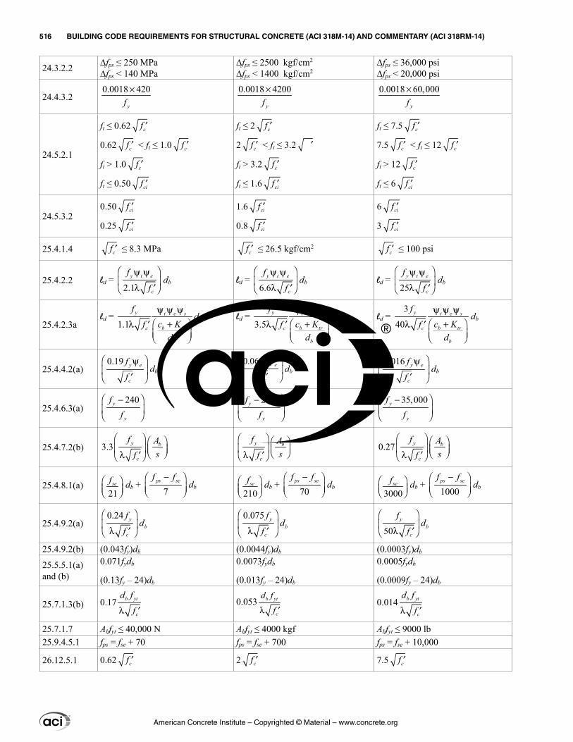
American Concrete Institute – Copyrighted © Material – www.concrete.org
516 BUILDING CODE REQUIREMENTS FOR STRUCTURAL CONCRETE (ACI 318M-14) AND COMMENTARY (ACI 318RM-14)
24.3.2.2 ∆fps ≤ 250 MPa∆fps < 140 MPa
∆fps ≤ 2500 kgf/cm2
∆fps < 1400 kgf/cm2∆fps ≤ 36,000 psi∆fps < 20,000 psi
24.4.3.20.0018 420×
yf0.0018 4200×
yf0.0018 60,000×
yf
24.5.2.1
ft ≤ 0.62 cf ′
0.62 cf ′ < ft ≤ 1.0 cf ′
ft > 1.0 cf ′
ft ≤ 0.50 cif ′
ft ≤ 2 cf ′
2 cf ′ < ft ≤ 3.2 ′
ft > 3.2 cf ′
ft ≤ 1.6 cif ′
ft ≤ 7.5 cf ′
7.5 cf ′ < ft ≤ 12 cf ′
ft > 12 cf ′
ft ≤ 6 cif ′
24.5.3.20.50 cif ′
0.25 cif ′
1.6 cif ′
0.8 cif ′
6 cif ′
3 cif ′
25.4.1.4 cf ′ ≤ 8.3 MPa cf ′ ≤ 26.5 kgf/cm2cf ′ ≤ 100 psi
25.4.2.2 ld = 2.1
t
c
y ef
f
ψ ψ λ ′
db ld = 6.6
t
c
y ef
f
ψ ψ λ ′
db ld = 25
y
c
t ef
f ′
ψ ψ λ
db
25.4.2.3ald =
1.1y t e s
bc tr
b
fc Kf
d
ψ ψ ψλ ′ +
db ld = 3.5
y t e s
bc tr
b
fc Kf
d
ψ ψ ψλ ′ +
db ld = 3
40y t e s
bc tr
b
fc Kf
d
ψ ψ ψλ ′ +
db
25.4.4.2(a)0.19 y e
c
f
f ′
ψ
db0.06 y e
c
f
f ′
ψ
db0.016 y e
c
f
f ′
ψ
db
25.4.6.3(a)240y
y
ff
−
2460y
y
ff
−
35,000y
y
ff
−
25.4.7.2(b) 3.3c
y bf Asf
λ ′
y b
c
fsfA
λ ′0.27 y b
c
f Af s
′ λ
25.4.8.1(a)21
sef
db + 7
ps sef f−
db210
sef
db + 70
ps sef f−
db3000
sef
db + 1000ps sef f−
db
25.4.9.2(a)0.24
c
ybd
f
f λ ′
0.075 yb
cf
fd
′λ 50 c
yb
fd
f
′λ
25.4.9.2(b) (0.043fy)db (0.0044fy)db (0.0003fy)db
25.5.5.1(a) and (b)
0.071fydb
(0.13fy – 24)db
0.0073fydb
(0.013fy – 24)db
0.0005fydb
(0.0009fy – 24)db
25.7.1.3(b) 0.17 b yt
c
d f
fλ ′0.053 b yt
c
d f
fλ ′0.014 b yt
c
d f
fλ ′
25.7.1.7 Abfyt ≤ 40,000 N Abfyt ≤ 4000 kgf Abfyt ≤ 9000 lb25.9.4.5.1 fps = fse + 70 fps = fse + 700 fps = fse + 10,000
26.12.5.1 0.62 cf ′ 2 cf ′ 7.5 cf ′

INDEXAcceptance criteria
- load test, 27.4.5- standard-cured specimens, 26.12.3- steel fiber-reinforced concrete, 26.12.5
Admixtures, 26.4.1.4Aggregates, 26.4.1.2Alternative construction materials, 1.10Anchoring, Ch. 17
- adhesive bond strength, 17.4.5- anchor strength, 17.4.1, 17.5.1- breakout strength in shear, 17.5.2- breakout strength in tension, 17.4.2- brittle steel element, 17.3.3- construction documents, 26.7- ductile steel element, 17.3.3- edge distances, spacings, and thicknesses, 17.7- installation and inspection, 17.8- pryout, 17.5.3- pullout strength, 17.4.3- reduction factors, 17.3.3- seismic design, 17.2.3- side-face blowout, 17.4.4- shear loading, 17.5- stretch length, 17.2.3.4.3- sustained tension load, 17.3.1.2- tensile and shear interaction, 17.6- tensile loading, 17.4
Anchorage zone, 25.9Axial strength, 22.4
Bar bending, 26.6.3Beam-column joint, Ch. 15
- not participating, 18.14.3- ordinary moment frames, 18.4.4- special moment frames, 18.8
Beams, Ch. 9- coupling beams, 18.10.7- direct design method, 8.10.5.7- intermediate moment frames, 18.4.2- not participating, 18.14.3- not participating, 18.14.3, 18.14.4- ordinary moment frames, 18.3.2- simplified method of analysis, 6.5- special moment frames, 18.6- structural integrity, 9.7.7
Bearing- plain concrete, 14.5.6- reinforced concrete, 22.8
Bend diameters, 25.3Bottle-shaped struts, 23.4Boundary elements, 12.5Brackets and corbels, 16.5Building official, 1.6, 1.8.2, 1.10.1Bundled reinforcement, 25.6
Caissons, 1.4.6, 13.4.3, 18.13.4Cementitious materials, 26.4.1.1
Cold weather, 26.5.4Collector reinforcement, 12.7.3Collectors, 12.5.4, 18.12.3Columns, Ch. 10
- composite columns, 4.12.4, 10.2.2- direct design method, 8.10.7- equivalent frame method, 8.11.4- intermediate moment frames, 18.4.3- not participating, 18.14.3, 18.14.4- ordinary moment frames, 18.3.3- special moment frames, 18.7
Combined flexural and axial strength, 22.4Composite columns, 10.2.2Composite flexural members
- flexure, 22.3.3- general, 4.12.3- horizontal shear, 16.4- vertical shear, 22.5.4
Composite steel deck, 1.4.9Concrete
- characteristics, 26.4.4- cover, 20.6.1- design properties, 19.2- durability requirements, 19.3- materials, 26.4.1- mixture requirements, 19.3.2, 26.4.2- modulus of elasticity, 19.2.2- modulus of rupture, 19.2.3- placement and consolidation, 26.5.2- production, 26.5.1- proportioning, 26.4.3
Connections, Ch. 16- foundations, 16.3- precast members, 16.2
Construction, 4.13, 26.5.7Construction, joints, 14.3.4, 18.10.9, 26.5.6Construction documents, 1.8, Ch. 26Corrosion protection
- external post-tensioning, 20.6.6- grouted tendons, 20.7.4- post-tensioning hardware, 20.7.5- unbonded prestressing reinforcement, 20.6.3
Coupling beams, 18.10.7Cracking torsion, 22.7.5Crossties, 18.6.4.3, 18.7.5.2, 18.10.7.4, 25.3Curing, 26.5.3
Deep beams, 9.9Deep foundations, 13.4Definitions, 2.1Deflections, 24.2Design loads, 4.3, Ch. 5Design records, 1.8Development length, 25.4
- deformed bar and wire in compression, 25.4.9- deformed bar and wire in tension, 25.4.2- excess reinforcement reduction factor, 25.4.10
American Concrete Institute – Copyrighted © Material – www.concrete.org
INDEX 517
- headed deformed bars, 25.4.4- mechanically anchored deformed bars, 25.4.5- pretensioned seven-wire strands, 25.4.8- standard hooks, 25.4.3- welded deformed wire reinforcement, 25.4.6- welded plain wire reinforcement, 25.4.7
Diaphragms, 4.4.7, Ch. 12- composite topping, 18.12.4- collector, 12.5.4- noncomposite topping, 18.12.5- shrinkage and temperature reinforcement, 12.6
Direct design method, 8.10Drilled pier, 1.4.6, 13.4.3, 18.13.4Durability, 4.8, 19.3, 20.6
Earthquake-resistant structures, Ch. 18Elastic second-order analysis, 6.7
- section properties, 6.7.2Embedments, 20.7, 26.8End-bearing splices, 25.5.6Epoxy-coated reinforcement, 20.6.2Equilibrium and strain compatibility, 22.2.1Equivalent frame method, 8.11Existing structures, 4.14, Ch. 27
- acceptance criteria, 27.4.5- analytical strength evaluation, 27.3- strength evaluation by load test, 27.4- strength reduction factors, 27.3.2
Exposure categories and classes, 19.3.1
Finite element analysis, 6.9Fire resistance, 4.11First-order analysis, 6.6
- redistribution of moments in flexural members, 6.6.5- section properties, 6.6.3- moment magnification method, 6.6.4
Flexural strength, 22.3Folded plates, 1.4.3Formwork, 26.11Foundations, Ch. 13, 14.4.3, 18.13Freezing and thawing, 19.3
General building code, 1.2.2, 1.2.5, 1.2.7, 1.4.1, 1.4.2, 1.9.2Grade beams, 13.3.2, 18.13.3
Headed shear stud reinforcement, 8.7.7, 20.5Hoops, 25.7.4Horizontal shear transfer, 16.4Hot weather, 26.5.5
Immediate deflection, 24.2.3Inspection, 1.9, 4.13, 17.8, 26.13Intermediate moment frames
- cast-in-place, 18.4- precast, 18.2
Intermediate structural walls- precast, 18.5
Inelastic second-order analysis, 6.8
Investigation of low strength-test results, 26.12.4
Jurisdiction, 1.2.2, 1.2.6, 1.5.7, 1.6.2, 1.8.1
Lap splices- deformed bars and deformed wires in tension, 25.5.2- deformed bars in compression, 25.5.5- welded deformed wire reinforcement in tension, 25.5.3- welded plain wire reinforcement in tension, 25.5.4
Licensed design professional, 1.7Lift-slab construction, 8.9Lightweight concrete, 19.2.4Live load arrangement, 6.4Loads
- flood, 5.3.9- fluid load, 5.3.7- ice load, 5.3.10- lateral earth pressure, 5.3.8- live load, 5.3.3, 5.3.4- load factors and combinations, 5.3- post-tensioned anchorage zone design, 5.3.12- volume change and differential settlement, 5.3.6- wind load, 5.3.5
Load path, 4.4, 18.12.3Load test, 27.4
Mat foundations, 13.3.4, 18.13.2Mechanical splices, 18.2.7, 25.5.7Members not part of seismic-force-resisting system, 18.14Modulus of elasticity
- concrete, 19.2.2- nonprestressed steel and wires, 20.2.2.2- prestressing steel, 20.3.2.1
Modulus of rupture, 19.2.3Moment magnification method, 6.6.4
Noncomposite steel deck, 1.4.4Non-prestessed reinforcement
- design properties, 20.2.2- material properties, 20.2.1
Notation, 2.2
Offset bent longitudinal reinforcement, 10.7.4One-way joist systems, 9.8One-way shallow foundations, 13.3.2One-way shear, 22.5One-way slabs, Ch. 7
- simplified method of analysis, 6.5Offset bent longitudinal bars, 10.7.6.4Ordinary moment frames, 18.3
Pedestals, 14.3.3Piers, 18.13.4Piles, 1.4.6, 13.4.3, 18.13.4Pile caps, 13.4.2, 18.13.2Placement, 26.6.2Plain concrete, Ch. 14Post-tensioning anchorages, 25.8
American Concrete Institute – Copyrighted © Material – www.concrete.org
518 BUILDING CODE REQUIREMENTS FOR STRUCTURAL CONCRETE (ACI 318M-14) AND COMMENTARY (ACI 318RM-14)
Post-tensioning couplers, 25.8Precast concrete
- connections, 16.2.4- construction documents, 26.9- plain concrete, 14.2.3- structural integrity, 16.2.5
Precast concrete systems, 4.12.1Prestressed concrete
- construction documents, 26.10- member classification, 24.5.2- permissible stresses, 24.5
Prestressed concrete systems, 4.12.2Prestressing reinforcement, 20.3
- design properties, 20.3.2- material properties, 20.3.1- permissible tensile stresses, 20.3.2.5- prestress losses, 20.3.2.6
Radius of gyration, 6.2.5.1Reinforcement materials, Ch. 20, 26.6
Sectional strength assumptions- concrete, 22.2.2- moment and axial strength, 22.2- nonprestressed reinforcement, 22.2.3- prestressing reinforcement, 22.2.4
Seismic design category, 4.4.6.1, 18.2.1.1Seismic hooks, 25.3Seismic-force-resisting system, 4.4.6Service load analysis, 6.6.3.2Serviceability, 4.7, Ch. 24Shallow foundations, 13.3Shear friction, 22.9Shearheads, 22.6.9Shells, 1.4.3Shrinkage and temperature reinforcement, 24.4
- diaphragm, 12.6- one-way slab, 7.6.4- two-way slab, 8.8.1.7
Slab-column connections, Ch. 15, 18.14.5Slabs-on-ground, 1.4.7, 13.2.4, 18.13.3Slender walls, 11.8Slenderness effect, 6.2.5Special moment frames
- cast-in-place, 18.6, 18.7, 18.8- precast, 18.9
Special structural walls- cast-in-place, 18.10- precast, 18.11
Special systems of design, 1.10Specified compressive strength, 19.2.1Specified concrete cover, 20.6.1Spirals, 25.7.3Splices, 25.5Stability properties, 6.6.4.4Stainless-steel reinforcement, 20.2.1.3Standards, Ch. 3Standard hooks, 25.3
Steel fiber reinforcement, 26.4.1.5Stirrups, 25.7.1Strength, 4.6Strength evaluation, 27.3Strength reduction factors, Ch. 21Structural analysis, 4.5, Ch. 6Structural integrity, 4.10Structural steel, pipe, and tubing, 20.4Structural systems, 4.4, 18.2Strut-and-tie
- bottle-shaped strut, 23.4.3- discontinuity, 23.1.2- nodal zones, 23.9- struts, 23.4- ties, 23.7
Sustainability, 4.9
T-beam- construction, 9.2.4- geometry, 6.3.2- one-way slab, 7.5.2.3- reinforcement distribution, 24.3.4- seismic, 18.7.2
Tanks, 1.4.8Terminology, 2.3Ties, 25.7.2Time-dependent deflection, 24.2.4Torsion, 22.7
- beam, 9.5.4- column, 10.5.4
Transfer of column axial force through the floor system, 15.3Transverse reinforcement, 25.7Trusses, 18.12.11Two-way combined footings, 13.3.4Two-way isolated footings, 13.3.3Two-way joist systems, 8.8Two-way shear, 22.6Two-way slabs, 6.2.4.1, 6.4.3, Ch. 8, 18.4.5
- openings, 8.5.4
Wall piers, 18.5.2.3, 18.10.8, 18.14.6Walls, Ch. 11
- alternative design method, 11.8- boundary element of special structural wall, 18.10.6- construction joints, 18.10.9- direct design method, 8.10.7- effective length, 11.5.3.2- load distribution, 11.2.3- minimum thickness, 11.3.1- pier, 18.10.8- plain concrete, 14.3.1, 14.4.2- precast special structural, 18.11- reinforcement around openings, 11.7.5- simplified design method, 11.5.3
Water, 26.4.1.3Welded splices, 18.2.8, 25.5.7Welding, 26.6.4Zinc-coated reinforcement, 20.6.2
American Concrete Institute – Copyrighted © Material – www.concrete.org
INDEX 519
The American Concrete Institute envisions a future where everyone has the knowledge needed to use concrete effectively to meet the demands of a changing world.
Founded in 1904 and headquartered in Farmington Hills, Michigan, USA, the American Concrete Institute is always advancing by developing educational programs, publishing technical documents, managing various certification programs, and hosting industry-wide events. With 99 chapters, 65 student chapters, and nearly 20,000 members spanning over 120 countries, the American Concrete Institute has always retained the same basic mission — to develop and disseminate consensus-based knowledge on concrete and its uses.
In today’s market, it is imperative to be knowledgeable and have an edge over the competition. ACI membership provides concrete industry professionals the chance to save money and time, while increasing productivity, competitiveness, and awareness of new technology and cutting-edge research. Learn more and become a member at http://www.concrete.org.
ACI 318-14 Resources
ACI offers a comprehensive slate of resources for designing and constructing according to ACI 318-14, “Building Code Requirements for Structural Concrete.” These resources include:
Transition keys that map provisions from 318-14 to 318-11, and 318-11 to 318-14;
318-14 Seminars that provide reorganization details and technical updates through comprehensive day-long seminars at your office or a location near you;
318-14 Webinars that provide reorganization details and technical updates from your desktop; and
ACI’s new Reinforced Concrete Design Manual including explanations, analyses, examples, and design aids for reinforced concrete structures (in accordance with 318-14).
Learn more about these transition resources at http://www.concrete.org/aci318.
American Concrete Institute38800 Country Club DriveFarmington Hills, MI 48331Phone: +1.248.848.3700www.concrete.org

38800 Country Club Drive
Farmington Hills, MI 48331 USA
+1.248.848.3700
www.concrete.org
The American Concrete Institute (ACI) is a leading authority and resource
worldwide for the development and distribution of consensus-based
standards and technical resources, educational programs, and certifications
for individuals and organizations involved in concrete design, construction,
and materials, who share a commitment to pursuing the best use of concrete.
Individuals interested in the activities of ACI are encouraged to explore the
ACI website for membership opportunities, committee activities, and a wide
variety of concrete resources. As a volunteer member-driven organization,
ACI invites partnerships and welcomes all concrete professionals who wish to
be part of a respected, connected, social group that provides an opportunity
for professional growth, networking and enjoyment.
9 781942 727118