Embed Size (px)
Citation preview

JK Geotechnics GEOTECHNICAL & ENVIRONMENTAL ENGINEERS
PO Box 976, North Ryde BC NSW 1670 Tel: 02 9888 5000 Fax: 02 9888 5001 www.jkgeotechnics.com.au
Jeffery & Katauskas Pty Ltd, trading as JK Geotechnics ABN 17 003 550 801
REPORT
TO
TKD ARCHITECTS
ON
GEOTECHNICAL INVESTIGATION
FOR
PROPOSED SCHOOL BUILDING
AT
RIVERBANK PUBLIC SCHOOL
25 WENTWORTH STREET, THE PONDS, NSW
20 September 2016
Ref: 29696ZHrpt
29696ZHrpt Page ii
Date: 20 September 2016 Report No: 29696ZHrpt Revision No: 0
Report prepared by: Adrian Hulskamp Senior Associate | Geotechnical Engineer
Report reviewed by: Agi Zenon Principal | Geotechnical Engineer For and on behalf of
JK GEOTECHNICS
PO Box 976
NORTH RYDE BC NSW 1670
Document Copyright of JK Geotechnics.
This Report (which includes all attachments and annexures) has been prepared by JK Geotechnics (JKG) for its Client, and is intended for the use only by that Client. This Report has been prepared pursuant to a contract between JKG and its Client and is therefore subject to:
a) JKG’s proposal in respect of the work covered by the Report;
b) the limitations defined in the Client’s brief to JKG;
c) the terms of contract between JK and the Client, including terms limiting the liability of JKG. If the Client, or any person, provides a copy of this Report to any third party, such third party must not rely on this Report, except with the express written consent of JKG which, if given, will be deemed to be upon the same terms, conditions, restrictions and limitations as apply by virtue of (a), (b), and (c) above. Any third party who seeks to rely on this Report without the express written consent of JKG does so entirely at their own risk and to the fullest extent permitted by law, JKG accepts no liability whatsoever, in respect of any loss or damage suffered by any such third party. At the Company’s discretion, JKG may send a paper copy of this report for confirmation. In the event of any discrepancy between paper and electronic versions, the paper version is to take precedence. The USER shall ascertain the accuracy and the suitability of this information for the purpose intended; reasonable effort is made at the time of assembling this information to ensure its integrity. The recipient is not authorised to modify the content of the information supplied without the prior written consent of JKG.
29696ZHrpt Page iii
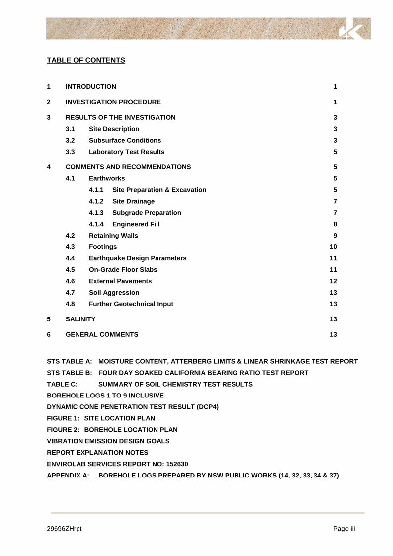
TABLE OF CONTENTS
1 INTRODUCTION 1
2 INVESTIGATION PROCEDURE 1
3 RESULTS OF THE INVESTIGATION 3
3.1 Site Description 3
3.2 Subsurface Conditions 3
3.3 Laboratory Test Results 5
4 COMMENTS AND RECOMMENDATIONS 5
4.1 Earthworks 5
4.1.1 Site Preparation & Excavation 5
4.1.2 Site Drainage 7
4.1.3 Subgrade Preparation 7
4.1.4 Engineered Fill 8
4.2 Retaining Walls 9
4.3 Footings 10
4.4 Earthquake Design Parameters 11
4.5 On-Grade Floor Slabs 11
4.6 External Pavements 12
4.7 Soil Aggression 13
4.8 Further Geotechnical Input 13
5 SALINITY 13
6 GENERAL COMMENTS 13
STS TABLE A: MOISTURE CONTENT, ATTERBERG LIMITS & LINEAR SHRINKAGE TEST REPORT
STS TABLE B: FOUR DAY SOAKED CALIFORNIA BEARING RATIO TEST REPORT
TABLE C: SUMMARY OF SOIL CHEMISTRY TEST RESULTS
BOREHOLE LOGS 1 TO 9 INCLUSIVE
DYNAMIC CONE PENETRATION TEST RESULT (DCP4)
FIGURE 1: SITE LOCATION PLAN
FIGURE 2: BOREHOLE LOCATION PLAN
VIBRATION EMISSION DESIGN GOALS
REPORT EXPLANATION NOTES
ENVIROLAB SERVICES REPORT NO: 152630
APPENDIX A: BOREHOLE LOGS PREPARED BY NSW PUBLIC WORKS (14, 32, 33, 34 & 37)

29696ZHrpt Page 1
1 INTRODUCTION
This report presents the results of a geotechnical investigation for the proposed school building at
Riverbank Public School, 25 Wentworth Street, The Ponds, NSW. A site location plan is attached
as Figure 1. The investigation was commissioned by TKD Architects in an email, dated 12 August
2016. The commission was on the basis of our proposal (Ref P43116Z) dated 10 August 2016,
with the request that the fieldwork was carried out on a weekend.
Based on the supplied undated Woolacotts briefing letter (Reference: 16-162), we understand that
the project is at a concept stage and will include construction of a new on-grade two storey concrete
framed building, with column loads in the order of 1,000kN. The location of the proposed school
building and the finished floor level of the proposed ground floor have not yet been finalised.
However, we have assumed that the proposed ground floor level will be at a similar level to existing
site levels. External pavements will be constructed around the proposed building.
The purpose of the investigation was to obtain geotechnical information on subsurface conditions
at nine nominated borehole locations, and based on the results obtained, to present our comments
and recommendations on earthworks, retaining walls, footings, on-grade floor slabs, external
pavements, earthquake design parameters and soil aggression.
We were also commissioned to carry out a Preliminary Stage 1 Environmental Site Assessment.
This work was carried out by our specialist environmental division, EIS, who prepared a report
(Ref E29696KDrpt) dated September 2016. This geotechnical report must be read in conjunction
with the EIS report.
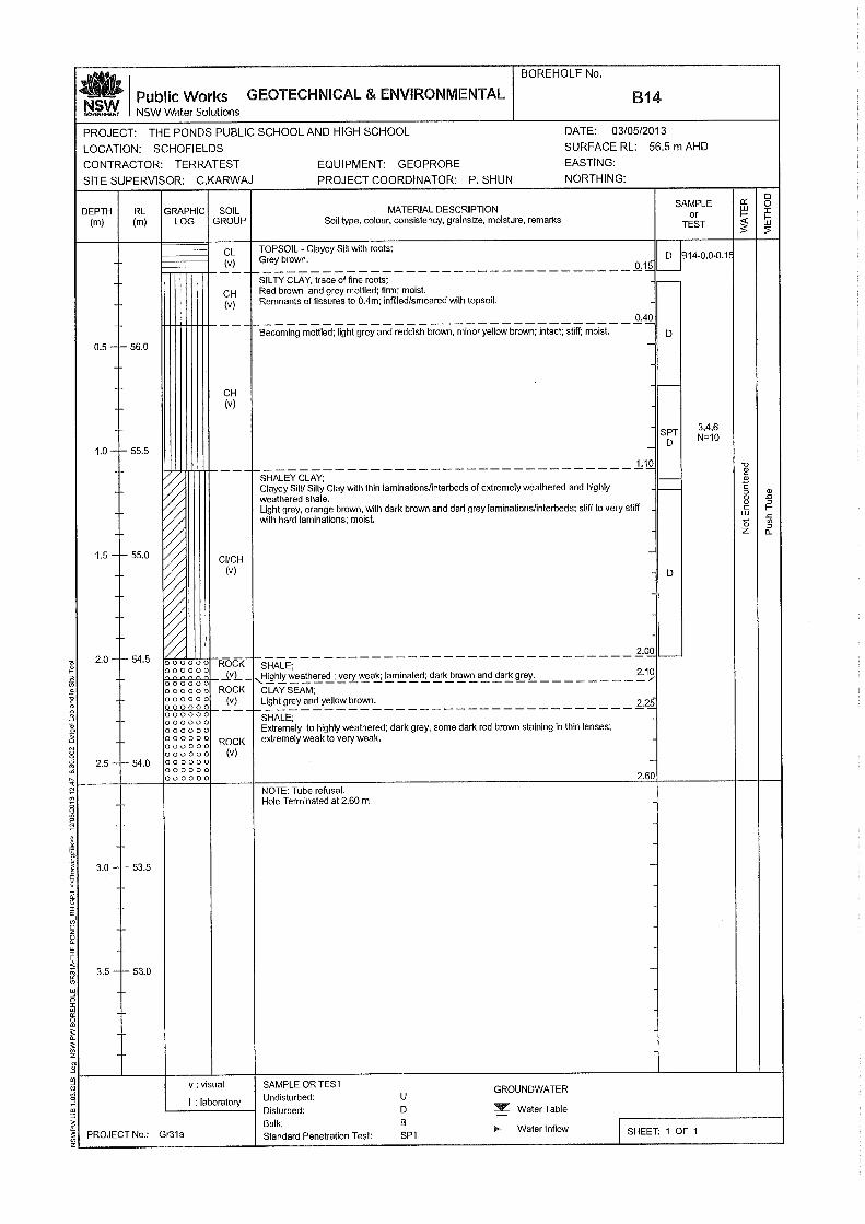
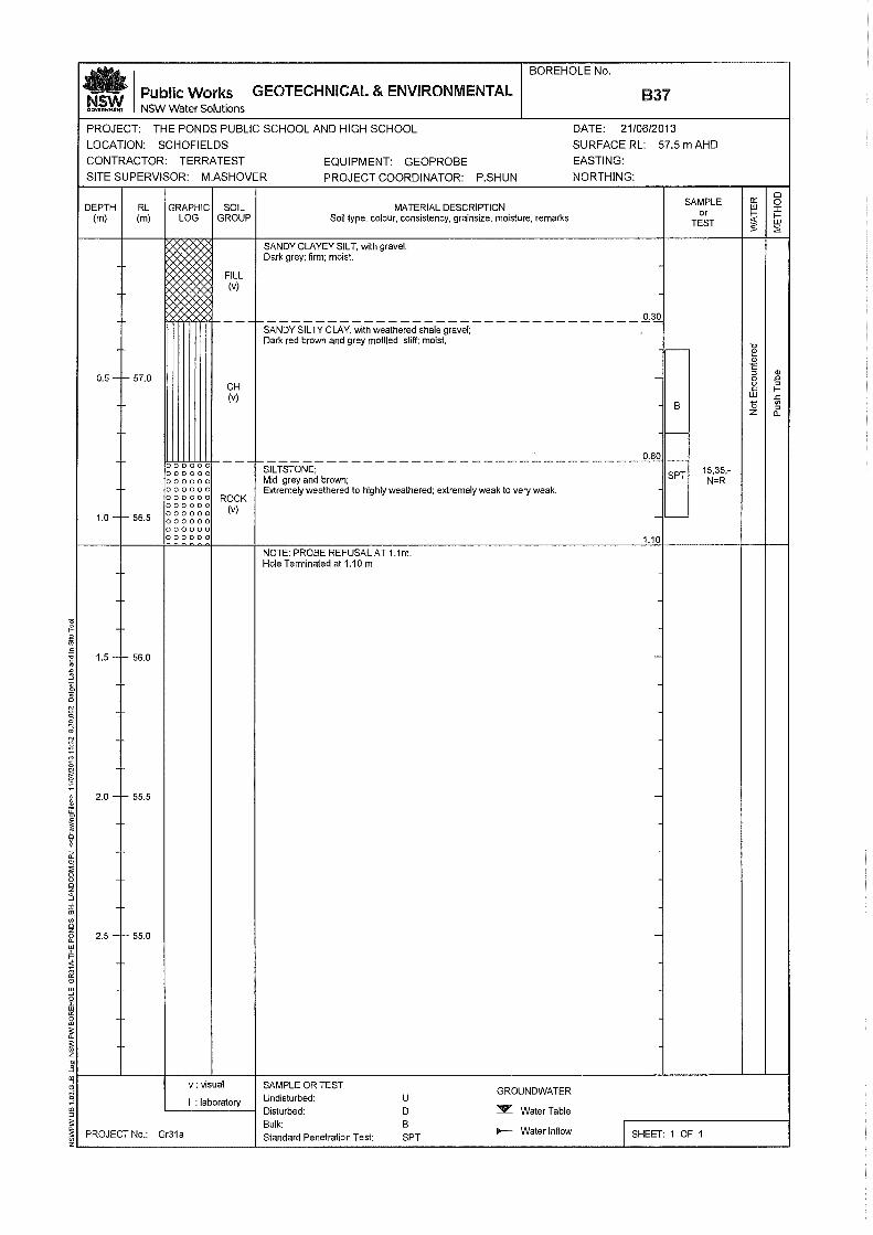
We have also been supplied with a report (Ref 13-GR31B, dated July 2013) prepared by NSW
Public Works for a previous geotechnical investigation completed at the site for the current Public
and High School buildings. The relevant borehole logs for the subject site (B14, B32, B33, B34 and
B37) have been referred to in preparation of this report and are attached in Appendix A for ease of
reference.
2 INVESTIGATION PROCEDURE
Prior to the commencement of the fieldwork, a ‘Dial Before You Dig’ (DBYD) search was undertaken
and the borehole locations were electromagnetically scanned by a specialist sub-contractor for
buried services.
29696ZHrpt Page 2
The fieldwork was carried out on 27 August 2016 and comprised the auger drilling of eight
boreholes (BH1 to BH3 and BH5 to BH9) to depths between 1.0m and 4.6m using our track
mounted JK300 drill rig equipped for site investigation purposes. Where access for the rig was not
possible, a hand augered borehole was drilled to a refusal depth of 0.7m. A Dynamic Cone
Penetration (DCP) test was carried out at BH4 to a refusal depth of 0.7m. The boreholes locations
were drilled as close as practical to the nominated locations shown on the annotated aerial
photograph attached to an email sent by TKD Architects on 23 August 2016.
The borehole locations, which are shown on the attached Figure 2, were set out by tape
measurements off existing surface features. The surface RLs shown on the borehole logs were
estimated by interpolation between spot levels shown on the supplied survey plan (Drawing No.
58574003A, dated 18 August 2016) prepared by Hill and Blume Consulting Surveyors and are
therefore only approximate. The survey datum is the Australian Height Datum (AHD). Figure 2 is
based on a combination of a Google Earth image of the site and the supplied survey plan.
The nature and composition of the subsurface soil and rock horizons were assessed by logging the
materials recovered during drilling. The relative compaction and strength of the subsoil profile were
assessed from the Standard Penetration Test (SPT) ‘N’ values and interpretation of the DCP test
results, augmented by hand penetrometer readings on samples obtained in the SPT split spoon
sampler and by tactile examination. The strength of the bedrock profile was assessed by
observation of auger penetration resistance when using a tungsten carbide (TC) bit, together with
examination of the recovered rock cuttings and correlation with subsequent moisture content tests.
We note that rock strengths assessed in this way are approximate and variances in one order of
rock strength should not be unexpected. Groundwater observations were made in each borehole
during the fieldwork. Further details of the methods and procedures employed in the investigation
are presented in the attached Report Explanation Notes.
Our geotechnical engineer (Michael Serra) was present on a full-time basis during the fieldwork to
set out the borehole locations, direct the electromagnetic scanning, nominate the testing and
sampling and prepare the attached borehole logs. The Report Explanation Notes define the logging
terms and symbols used.
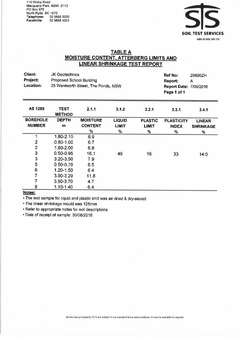
Selected soil and rock cutting samples were returned to NATA registered laboratories (Soil Test
Services Pty Ltd [STS] and Envirolab Services Pty Ltd) for moisture content, Atterberg Limits, linear
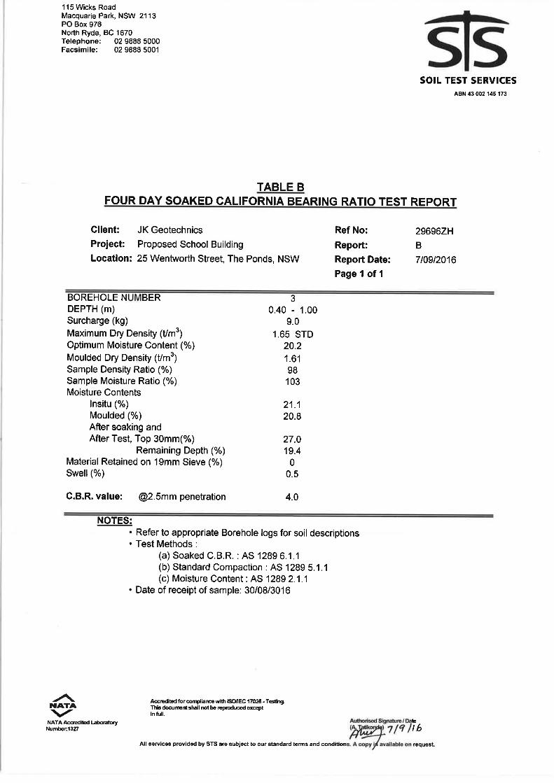
shrinkage, soil pH, chloride, sulphate and resistivity, Standard Compaction and four day soaked
29696ZHrpt Page 3
CBR testing. The test results are summarised in the attached Tables A, B and C. The Envirolab
Services Pty Ltd ‘Certificate of Analysis’ is attached to this report.
3 RESULTS OF THE INVESTIGATION
3.1 Site Description
The site is located in slightly undulating topography on the side of a gently sloping north-west facing
hillside which grades at about 3°. The site is occupied by Riverbank Public school, which is bounded
by Riverbank Drive and Wentworth Street to the south-west and east, respectively.
At the time of the fieldwork, the southern end of the school comprised a relatively flat grass covered
playing field, which appeared to have been cut into the hillside to a maximum depth of about 1.5m
on the southern and western sides of the field. The cut batter slopes graded between about 15°
and 25° and were also grass covered. There were several small trees scattered around the
perimeter of the playfield field behind the crest of the above batter slopes. On the eastern side of
the playing field was an asphaltic concrete (AC) surfaced car park and concrete driveway, both of
which appeared to be in generally good condition. The northern portion of the school was occupied
by an AC surfaced basketball court, AC surfaced outdoor play areas, several one and two storey
brick and clad buildings as well as several demountable classroom buildings. All existing structures
appeared to be in good external condition, based on a cursory inspection from within the site.
The area on the northern side of the two storey building where BH4 was located, was covered with
concrete footpaths and garden beds. There was another two storey brick and clad building located
on the northern side of this area.
3.2 Subsurface Conditions
The 1:100,000 series geological map of Penrith (Geological Survey of NSW, Geological Series
Sheet 9030) indicates the site to be underlain by Bringelly Shale of the Wianamatta Group. The
formation comprises shale, carbonaceous claystone, claystone, laminite, fine to medium grained
lithic sandstone, rare coal and tuff.
In summary, the JK Geotechnics boreholes encountered fill overlying residual silty clays with
weathered shale and sandstone bedrock at generally relatively shallow depth. Reference should
be made to the attached borehole logs for details at each specific location. A summary of the
encountered subsurface characteristics is presented below. We have also provided a brief
29696ZHrpt Page 4
summary of the subsurface conditions encountered in the NSW Public Works boreholes referred to
Section 1 above. We infer though that the ground surface levels at the time of the NSW Public
Works were generally higher than existing levels based on a comparison of the RLs shown on the
borehole logs and the survey plan:
Fill
Fill comprising silty sand and silty clay was encountered from the ground surface in each borehole
and extended down to depths between 0.1m (BH6) and 1m (BH1). Inclusions of igneous gravel
were present within the fill. The fill in BH1, BH7 and BH9 was assessed to be moderately
compacted.
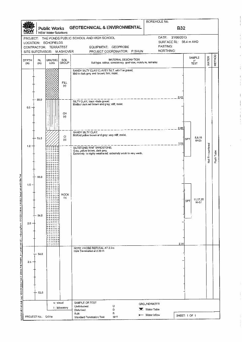
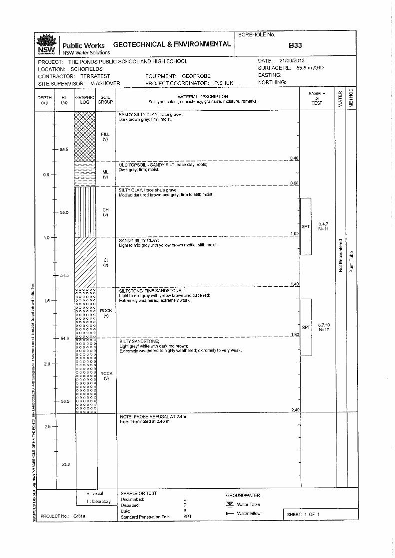
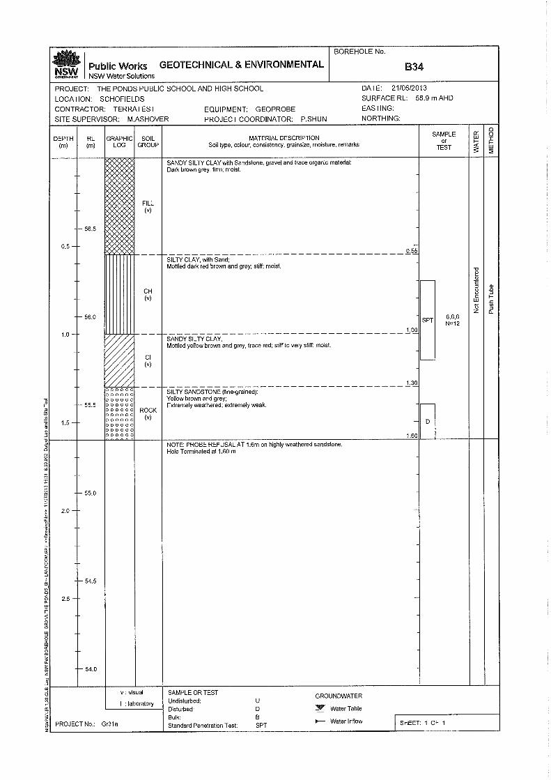
With the exception of B14, the previous NSW Public Works boreholes encountered clay and silt fill
from the ground surface down to depths between 0.3m and 0.55m. Inclusions of gravel were
present within the fill. A 200mm thick ‘old’ topsoil layer was encountered below the fill in B33.
Residual Silty Clay
Residual silty clay of medium to high plasticity and very stiff to hard strength was encountered in
BH1, BH3, BH6, BH7 & BH9.
The previous NSW Pubic Works boreholes encountered residual silty clay and sandy silty clay
below the fill and from the ground surface in B14. The strengths indicated were ‘firm to very stiff’’,
however, we note that no hand penetrometer tests were carried out on the clays. The previous
SPT ‘N’ infer at least very stiff clays.
Weathered Bedrock
Weathered shale, sandstone and siltstone bedrock and occasionally interbedded shale and
sandstone bedrock was encountered in each JK Geotechnics and NSW Public Works boreholes at
depths between 0.3m (BH5) and 1.9m (BH3) and extended down to the borehole termination
depths. We have interpreted that the ‘shaley clay’ logged on the NSW Public Works boreholes to
be extremely weathered shale. The bedrock was generally extremely weathered and of extremely
low strength at first contact but rapidly improved in most boreholes to distinctly and slightly
weathered rock of low, medium and high strength.
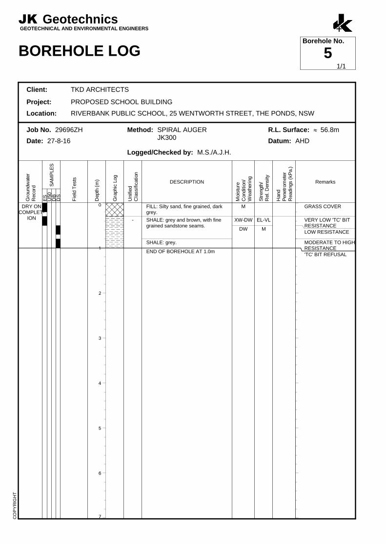
‘TC’ bit refusal occurred within the shale bedrock profile in BH1, BH2 and BH5 to BH9.
29696ZHrpt Page 5
Groundwater
Each JK Geotechnics and NSW Public Works borehole was ‘dry’ during and on completion of
drilling. We note that the groundwater levels may not have stabilised within the short observation
period. No long term groundwater monitoring was carried out.
3.3 Laboratory Test Results
The results of the moisture content tests carried out on recovered rock cutting samples generally
correlated well with our field assessment of bedrock strength.
The Atterberg Limits and linear shrinkage test result confirmed the sample tested was of medium
plasticity with a moderate to high potential for shrink-swell reactivity with changes in moisture
content.
The four day soaked CBR test carried out on a sample of medium plasticity residual silty clay from
BH3 resulted in a value of 4% when compacted to 98% of Standard Maximum Dry Density (SMDD)
and surcharged with 9kg. The insitu moisture content of the sample was 0.9% ‘wet’ of the Standard
Optimum Moisture Content (SOMC).
The soil pH test results showed the samples tested to be acidic (BH1) and alkaline (BH2). The
sulphate and chloride test results were low. The resistivity test results were relatively high.
4 COMMENTS AND RECOMMENDATIONS
4.1 Earthworks
All earthworks recommendations should be complemented by reference to AS3798-2007.
4.1.1 Site Preparation & Excavation
Within the proposed development footprint and following demolition of existing structures, if
required, all trees (including their root balls) should be removed, and all grass, topsoil and
root-affected soil and any deleterious or contaminated existing fill should be stripped. Stripped
topsoil, if present, and root affected soils should be stockpiled separately as they are not suitable
for reuse as engineered fill. They may, however, be reused for landscaping purposes. Reference
should be made to the EIS report for guidance on the offsite disposal of soil.
29696ZHrpt Page 6
We note that it is difficult to accurately assess the depth of topsoil and/or root affected soils in a
100mm diameter borehole. If considered to be an important contractual issue, we recommend that
a number of test pits be excavated across the proposed school building footprint to more accurately
assess the topsoil/root affected soil stripping depth. Alternatively, a geotechnical inspection could
be carried out after initial stripping to confirm the topsoil depth.
Excavation down to design subgrade level through the soil profile, where required, may be
completed using buckets fitted to a hydraulic excavator.
If excavation of bedrock is required to achieve design levels, then we recommend that prior to
excavation, dilapidation surveys be completed on structures located within 30m of the proposed
rock excavation. The dilapidation surveys should include detailed internal and external inspection
of these structures, where all defects including defect location, type, length and width are rigorously
described and photographed.
If the structures are located outside the subject site, the respective owners should be asked to
confirm that the dilapidation survey reports present a fair record of existing conditions. The
dilapidation survey reports may be used as a benchmark against which to assess possible future
damage claims. We could prepare a proposal to carry out the dilapidation surveys, if requested.
Excavation of extremely low or very low strength bedrock may be readily completed using a
‘digging’ bucket fitted to a large hydraulic excavator. If excavation of low and higher strength
bedrock is required, this would be most effectively excavated using hydraulic impact rock hammers.
The hydraulic impact rock hammers would also be required for detailed rock excavations such as
for footings, trenches, lift pits etc. Grid sawing techniques in conjunction with ripping or hammering
will help to facilitate excavation.
Dust suppression by spraying with water should be carried out whenever rock saws are being used.
Rock excavations using hydraulic rock hammers will need to be strictly controlled as there will
probably be direct transmission of ground vibrations to nearby structures and buried services.
We recommend that quantitative vibration monitoring be carried out whenever hydraulic rock
hammers are used during rock excavation on this site, as a precaution against possible vibration
induced damage. By referencing German Standard DIN4150-3:1999-02, the vibrations on the
adjacent structures, including nearby school buildings which are to remain, should be limited to a
peak particle velocity of 5mm/s, subject to review of the dilapidation survey reports. It should be
29696ZHrpt Page 7
noted when vibration limits are exceeded, the vibrations should be assessed against the attached
Vibration Emission Design Goals sheet, as higher vibrations may be acceptable depending on the
vibration frequency. If the vibration monitoring confirms that transmitted vibrations are excessive,
then it would be necessary to change to a smaller rock hammer. Alternatively, geotechnical advice
could be sought with respect to alternative excavation techniques.
We recommend that a copy of this report be provided to the excavation contractor so that they can
make their own assessment of excavation conditions.
4.1.2 Site Drainage
The clay subgrade at the site is expected to undergo a loss in strength when wet as evident by the
relatively low CBR value. Furthermore, the clay subgrade is expected to have a moderate to high
shrink-swell reactive potential. Therefore, it is important to provide good and effective site drainage
both during construction and for long-term site maintenance. The principle aim of the drainage is
to promote run-off and reduce ponding. A poorly drained clay subgrade may become untraffickable
when wet. The earthworks should be carefully planned and scheduled to maintain good cross-falls
during construction.
4.1.3 Subgrade Preparation
Following site stripping and excavation down to design subgrade level, where required, we
recommend that the subgrade over the proposed school building and pavement footprints be proof
rolled with at least six passes of a static smooth drum roller of at least 12 tonnes deadweight. The
final pass of proof rolling should be carried out under the direction of an experienced geotechnical
engineer for the detection of unstable or soft areas.
Where bedrock is present at design subgrade level, proof rolling of the bedrock surface is
considered unwarranted.
Subgrade heaving during proof-rolling may occur in areas where the clays have become ‘saturated’
or in areas where poorly compacted fil is present. Heaving areas should be locally removed to a
stable base and replaced with engineered fill, as outlined below in Section 4.1.4. Alternatively,
bridging layer support using high tensile geogrids and appropriately sized well graded durable
crushed rock could be considered.

29696ZHrpt Page 8
If soil softening occurs after rainfall periods, then the clay subgrade should be over-excavated to
below the depth of moisture softening and replaced with engineered fill. If the clay subgrade
exhibits shrinkage cracking, then the surface should be watered and rolled until the shrinkage
cracks are no longer evident.
Engineered fill must be used where site levels need to be raised.
4.1.4 Engineered Fill
Engineered fill comprising clayey soils should be compacted in maximum 200mm thick loose layers
to a density ratio between 98% and 102% of SMDD and at a moisture content within 2% of SOMC.
Engineered fill comprising well graded granular materials, such as crushed sandstone, should be
compacted in maximum 200mm thick loose layers to achieve a minimum density ratio of at least
98% of SMDD.
The compaction specification may be relaxed to achieve a minimum density ratio of 95% of SMDD,
if the engineered fill is within grass or landscaped garden areas.
All engineered fill materials must be ‘clean’, free of organic matter and contain a maximum particle
size not exceeding 75mm.
All engineered fill should either be retained or battered to a permanent slope no steeper than
1 Vertical (V) in 2 Horizontal (H). A flatter batter to 1V on 3H or even 1V on 4H may be preferred
in order to facilitate maintenance. All permanent fill batter slopes must be protected from erosion
by quickly establishing a vegetative cover, applying a reinforced shotcrete facing etc.
Where space permits, we recommend that engineered fill extend a horizontal distance of at least
1m beyond the design fill embankment slope so that adequate edge compaction can be achieved.
On completion of filling any excess fill can be trimmed off.
Backfilling of service trenches must also be carried out using engineered fill in order to reduce
post-construction settlements. Due to the reduced energy output of the rollers that can be placed
in trenches, backfilling should be carried out in 100mm thick loose layers and compacted using a
trench roller or a roller attachment fitted to an excavator. Due to the reduced loose layer thickness,
the maximum particle size of the backfill material should also reduce to 40mm. The compaction
specifications provided above are applicable, unless there is a stricter contract specification.
29696ZHrpt Page 9
Density tests should be carried out on the engineered fill to confirm the above specification is
achieved. The frequency of density testing for engineered fill should be as per the requirements
outlined in Table 8.1 of AS3798. We recommend Level 2 control of fill compaction be adhered to
on this site. Due to a potential conflict of interest, the geotechnical testing authority (GTA) should
be directly engaged by TKD Architects (or their representative) and not by the earthworks contractor
or sub-contractors.
We note that compaction of engineered fill behind retaining walls is very difficult. The use of a
single sized durable gravel, such as “blue metal” gravel or crushed concrete gravel (free of fines
and less than 10% brick), do not require significant compactive effort. Such material should be
nominally compacted using a hand operated vibrating plate (sled) compactor in 200mm thick loose
layers. A non-woven geotextile filter fabric such as Bidim A34 should be placed as a separation
layer immediately above the cut batter slope to control subsoil erosion. Provided the gravel backfill
is placed as recommended above, density testing of the gravel backfill would not be required. The
geotextile should then be wrapped over the surface of the gravel backfill and capped with at least
a 0.3m thick compacted layer of engineered fill.
4.2 Retaining Walls
The major consideration in the selection of earth pressures for the design of retaining walls is the
need to limit deformations occurring outside the excavations. If retaining walls are required, the
following characteristic earth pressure coefficients and subsoil parameters may be adopted.
For allowable bearing pressure recommendations, refer to Section 4.3 below.
For free-standing cantilever walls which are retaining areas where minor movements can be
tolerated (i.e. landscaped or garden bed areas), a triangular lateral earth pressure distribution
may be adopted with an ‘active’ earth pressure coefficient, Ka, of 0.35, for the soil profile
assuming a horizontal backfill surface.
For cantilever walls where the tops are restrained or which retain areas where movements
are to be reduced or for propped walls, a triangular lateral earth pressure distribution should
be adopted with an ‘at rest’ earth pressure coefficient, Ko, of 0.55, for the soil profile assuming
a horizontal backfill surface.
A bulk unit weight of 20kN/m3 should be adopted for the soil profile.
Any surcharge affecting the walls (eg. traffic loading, adjacent building footings, construction
loads, etc) should be taken into account in the wall design using the appropriate earth
pressure coefficient from above.
29696ZHrpt Page 10
The retaining walls should be designed as drained and measures taken to provide complete
and permanent drainage of the ground behind the walls. Subsurface drains should
incorporate a non-woven geotextile fabric (eg. Bidim A34) to act as a filter against subsoil
erosion.
Lateral toe restraint may be achieved by suitably embedding the retaining wall footing to
sufficient depth. The embedment depth design should be based on a triangular lateral earth
pressure distribution and a ‘passive’ earth pressure coefficient, Kp, of 2.8, assuming horizontal
ground in front of the wall. We note that significant movement is required in order to mobilise
the full passive pressure of a soil, and therefore a factor of safety of at least 2 should be
adopted to reduce such movements. Any localised excavations, such as for buried services,
in front of the walls should be taken into account in the embedment depth design.
Alternatively, lateral toe restraint may be achieved by keying the retaining wall into weathered
bedrock. An allowable lateral stress of 150kPa may be adopted for key design. Where there
is a change from founding in soil to rock, construction joints must be installed within the
retaining wall close to the change in founding conditions, so as to permit relative movements.
4.3 Footings
In BH1, mostly silty clay fill was encountered to 1.0m depth. No details on the existing fill (i.e.
placement method, compaction specification, density test records, etc.) have been provided to us
and therefore we assume that the existing fill is not a ‘controlled fill’ as outlined in Clause 1.8.13 of
AS2870-2011 “Residential slabs and Footings”. Therefore, the site as a whole is Class ‘P’. The
standard designs in AS2870 are unlikely to be applicable for the proposed building and the footing
system design must therefore be carried out using engineering principles.
The site is underlain by medium and high plasticity residual silty clay. Based on the laboratory test
results, the thickness of the residual soil profile and assuming the fill was placed at least five years
ago, we expect characteristic surface movements at this site to be approximately 40mm (i.e. a
Class ‘H1’ site, in accordance with AS2870-2011).
Based on the supplied column loads and often shallow, but variable, depth to the underlying
bedrock, we recommend that the proposed building be uniformly founded within the underlying
bedrock.
A combination of pad/strip footings and bored piles are likely to be required. Bored piles will be
required where the bedrock is at least 1.5m below the proposed ground floor level.
29696ZHrpt Page 11
Footings founded in bedrock may be designed for a maximum allowable bearing pressure of
700kPa. However, footings founded into low strength or stronger bedrock may be designed for a
maximum allowable end bearing pressure of 1,000kPa, provided at least the initial footing
excavations/pile holes are inspected by a geotechnical engineer to check that a satisfactory bearing
stratum has been achieved.
For bored piles, a maximum allowable shaft adhesion value (in compression) of 70kPa is applicable
within the bedrock profile, below a minimum 0.3m length requirement. We may be able to upgrade
this shaft adhesion value to 100kPa, subject to geotechnical inspection. For tension piles, the shaft
adhesion value should be halved. The shaft adhesion through the soil profile must be ignored due
to strain incompatibility.
All piles/footings should be drilled/excavated, cleaned out, inspected and poured with minimal
delay. If delays in pouring are envisaged, then we recommend that a concrete blinding layer be
provided over the bases to reduce deterioration due to weathering.
We recommend that the ground beam between footings be poured over a void former at least 50mm
thick so as to isolate the beams from the underlying clay soils.
4.4 Earthquake Design Parameters
Based on the investigation results and in accordance with AS1170.4–2007, a Hazard Factor (Z) of
0.08 is applicable for the site, together with a subsoil Class Be.
4.5 On-Grade Floor Slabs
Slab-on-grade construction is feasible for the proposed building provided the subgrade has been
prepared in accordance with recommendations described in Section 4.1.3 above. The design
parameters recommended in Section 4.6 below are appropriate.
The on-grade floor slab should be isolated from the walls, columns and footings of the proposed
building so as to permit relative movements. Joints in the concrete on-grade floor slab should be
designed to accommodate shear forces but not bending moments by using dowelled or keyed
joints.
We expect there will be differential movements between the walls/columns of the proposed building
and the ground floor slab, due to shrink-swell of the underlying clay soils, unless the building is

29696ZHrpt Page 12
directly underlain by bedrock. Careful detailing between the floor slabs and walls/columns will
therefore be required. To reduce the effects of shrink-swell movements in the underlying clays on
the proposed building, we recommend that the external walls of the building be protected with a
perimeter apron slab at least 2m wide and which has at least a 0.7m deep beam below the outside
edge of the slab which is graded away from the building. The gap between the building and apron
slab, as well as any transverse joints in the slab, must be appropriately sealed to prevent water
ingress.
4.6 External Pavements
Based on the investigation results, we recommend that the proposed pavements be designed on
the basis of a CBR value of 3% or a Short Term Young’s Modulus of 20MPa. This value takes into
account the presence of high plasticity clay at the site, which may result in slightly lower soaked
CBR values than the laboratory test result.
We recommend that all base course materials comprise DGB20 in accordance with RMA
Specification D&C 3051 unbound base. The DGB20 material should be compacted in maximum
200mm thick loose layers using a large smooth drum roller to at least 98% of Modified Maximum
Dry Density (MMDD). We recommend that all sub-base materials comprise DGS40 in accordance
with RMA Specification D&C 3051 unbound sub-base. The DGS40 material should be compacted
in maximum 200mm thick loose layers using a large smooth drum roller to at least 95% of MMDD.
Adequate moisture conditioning to within 2% of Modified Optimum Moisture Content (MOMC)
should be provided during placement so as to reduce the potential for material breakdown during
compaction.
Density tests should be regularly carried out on the granular pavement materials to confirm the
above specifications are achieved. The frequency of density testing should be as per the
requirements outlined in Table 8.1 of AS3798. Level 2 testing of fill compaction is the minimum
permissible in AS3798-2007. The GTA should be directly engaged by TKD Architects (or their
representative) and not by the earthworks contractor or sub-contractors.
Subsoil drains should be provided below the edges of the proposed pavements with invert levels
at least 200mm below design subgrade level. The drainage trenches should be excavated with a
uniform longitudinal fall to appropriate discharge points so as to reduce the likelihood of water
ponding. The subgrade should be graded to promote water flow towards the subsoil drains.
Discharge from the subsoil drains should be piped to the stormwater system.
29696ZHrpt Page 13
4.7 Soil Aggression
Based on the soil chemistry test results, a ‘mild’ exposure classification for concrete is applicable
in accordance with Table 6.4.2 (C) in AS2159-2009.
4.8 Further Geotechnical Input
We summarise below the recommended additional geotechnical input that needs to be carried out:
Proof rolling inspections.
Geotechnical inspection of footing excavations/pile holes.
Density testing of all engineered fill, sub-base and base course materials.
5 SALINITY
The site is located in an area where soil and groundwater salinity may occur. Salinity can affect the
longevity and appearance of structures as well as causing adverse horticultural and
hydrogeological effects. The local council has guidelines relating to salinity issues which should be
checked for relevance to this project.
6 GENERAL COMMENTS
The recommendations presented in this report include specific issues to be addressed during the
construction phase of the project. As an example, special treatment of soft spots may be required
as a result of their discovery during proof-rolling, etc. In the event that any of the construction phase
recommendations presented in this report are not implemented, the general recommendations may
become inapplicable and JK Geotechnics accept no responsibility whatsoever for the performance
of the structure where recommendations are not implemented in full and properly tested, inspected
and documented.
The long term successful performance of floor slabs and pavements is dependent on the
satisfactory completion of the earthworks. In order to achieve this, the quality assurance program
should not be limited to routine compaction density testing only. Other critical factors associated
with the earthworks may include subgrade preparation, selection of fill materials, control of moisture
content and drainage, etc. The satisfactory control and assessment of these items may require
judgment from an experienced engineer. Such judgment often cannot be made by a technician
who may not have formal engineering qualifications and experience. In order to identify potential
problems, we recommend that a pre-construction meeting be held so that all parties involved

29696ZHrpt Page 14
understand the earthworks requirements and potential difficulties. This meeting should clearly
define the lines of communication and responsibility.
Occasionally, the subsurface conditions between the completed boreholes may be found to be
different (or may be interpreted to be different) from those expected. Variation can also occur with
groundwater conditions, especially after climatic changes. If such differences appear to exist, we
recommend that you immediately contact this office.
This report provides advice on geotechnical aspects for the proposed civil and structural design.
As part of the documentation stage of this project, Contract Documents and Specifications may be
prepared based on our report. However, there may be design features we are not aware of or have
not commented on for a variety of reasons. The designers should satisfy themselves that all the
necessary advice has been obtained. If required, we could be commissioned to review the
geotechnical aspects of contract documents to confirm the intent of our recommendations has been
correctly implemented.
A waste classification will need to be assigned to any soil excavated from the site prior to offsite
disposal. Subject to the appropriate testing, material can be classified as Virgin Excavated Natural
Material (VENM), General Solid, Restricted Solid or Hazardous Waste. Analysis takes seven to
10 working days to complete, therefore, an adequate allowance should be included in the
construction program unless testing is completed prior to construction. If contamination is
encountered, then substantial further testing (and associated delays) should be expected.
We strongly recommend that this issue is addressed prior to the commencement of excavation on
site.
This report has been prepared for the particular project described and no responsibility is accepted
for the use of any part of this report in any other context or for any other purpose. If there is any
change in the proposed development described in this report then all recommendations should be
reviewed. Copyright in this report is the property of JK Geotechnics. We have used a degree of
care, skill and diligence normally exercised by consulting engineers in similar circumstances and
locality. No other warranty expressed or implied is made or intended. Subject to payment of all
fees due for the investigation, the client alone shall have a licence to use this report. The report
shall not be reproduced except in full.

Reference No: 29696ZH
Project: Proposed School Building
Borehole Sample Depth Sample Description pH Restivity Sulphate Chloride
Number (m) Units (ohm. cm) (mg/kg) (mg/kg)
BH1 1.5 - 1.65 Residual SILTY CLAY 5.3 4,400 110 150
BH2 0.5 - 0.52 Weathered BEDROCK 8.8 6,900 58 26
TABLE C
SUMMARY OF SOIL CHEMISTRY TEST RESULTS
SOIL pH, RESISTIVITY, SULPHATE AND CHLORIDE
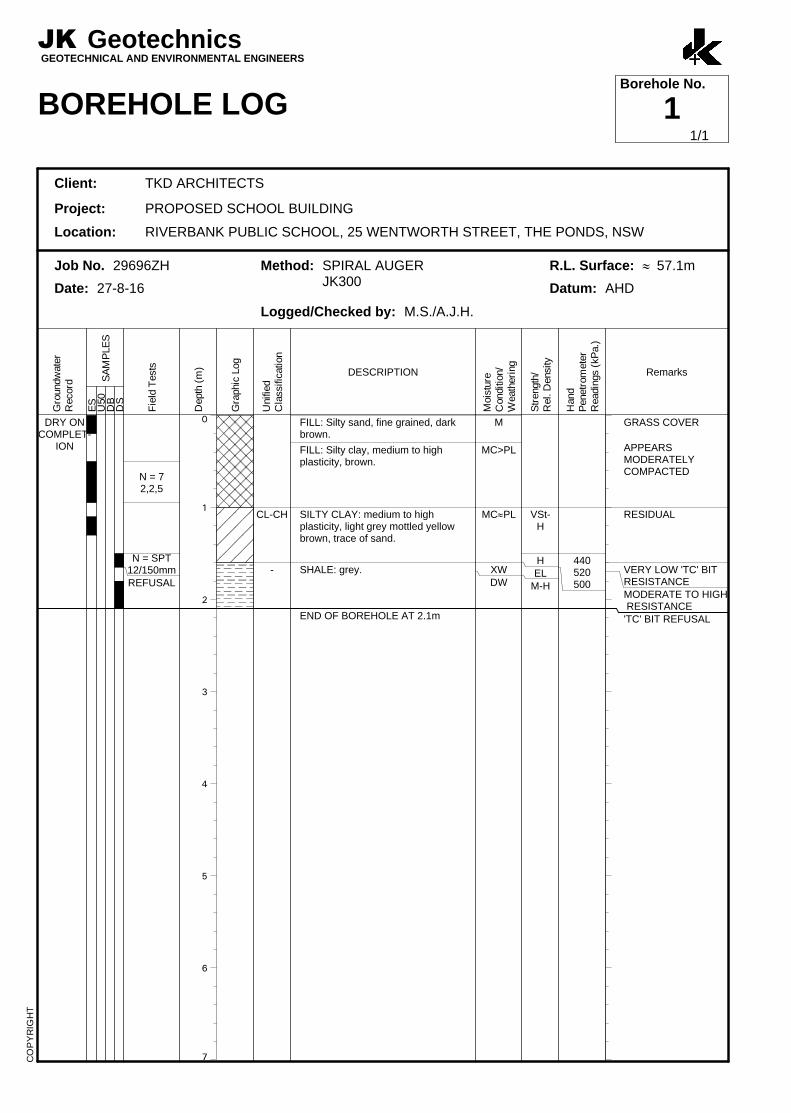
0
1
2
3
4
5
6
7
DRY ONCOMPLET-
ION
N = 72,2,5
N = SPT12/150mmREFUSAL
CL-CH
-
FILL: Silty sand, fine grained, darkbrown.
FILL: Silty clay, medium to highplasticity, brown.
SILTY CLAY: medium to highplasticity, light grey mottled yellowbrown, trace of sand.
SHALE: grey.
END OF BOREHOLE AT 2.1m
M
MC>PL
MC»PL
XWDW
VSt-H
HEL
M-H
440520500
GRASS COVER
APPEARSMODERATELYCOMPACTED
RESIDUAL
VERY LOW 'TC' BITRESISTANCEMODERATE TO HIGH RESISTANCE'TC' BIT REFUSAL
JK GeotechnicsGEOTECHNICAL AND ENVIRONMENTAL ENGINEERS
BOREHOLE LOGBorehole No.
1
Client: TKD ARCHITECTS
Project: PROPOSED SCHOOL BUILDING
Location: RIVERBANK PUBLIC SCHOOL, 25 WENTWORTH STREET, THE PONDS, NSW
Job No. 29696ZH Method: SPIRAL AUGERJK300
R.L. Surface: » 57.1m
Date: 27-8-16 Datum: AHD
Logged/Checked by: M.S./A.J.H.
Gro
undw
ate
rR
ecord
ES
SA
MP
LE
SU
50
DB
DS
Fie
ld T
ests
Depth
(m
)
Gra
phic
Log
Unifie
dC
lassific
ation
DESCRIPTION
Mois
ture
Conditio
n/
Weath
eri
ng
Str
ength
/R
el. D
ensity
Hand
Penetr
om
ete
rR
eadin
gs (
kP
a.)
Remarks
CO
PY
RIG
HT
1/1
0
1
2
3
4
5
6
7
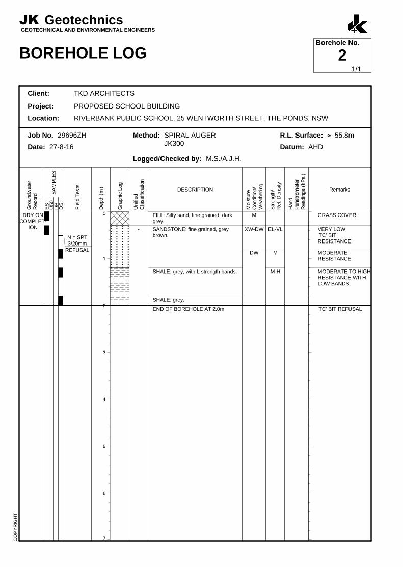
DRY ONCOMPLET-
ION
N = SPT3/20mm
REFUSAL
-
FILL: Silty sand, fine grained, darkgrey.
SANDSTONE: fine grained, greybrown.
SHALE: grey, with L strength bands.
SHALE: grey.
END OF BOREHOLE AT 2.0m
M
XW-DW
DW
EL-VL
M
M-H
GRASS COVER
VERY LOW'TC' BITRESISTANCE
MODERATERESISTANCE
MODERATE TO HIGHRESISTANCE WITHLOW BANDS.
'TC' BIT REFUSAL
JK GeotechnicsGEOTECHNICAL AND ENVIRONMENTAL ENGINEERS
BOREHOLE LOGBorehole No.
2
Client: TKD ARCHITECTS
Project: PROPOSED SCHOOL BUILDING
Location: RIVERBANK PUBLIC SCHOOL, 25 WENTWORTH STREET, THE PONDS, NSW
Job No. 29696ZH Method: SPIRAL AUGERJK300
R.L. Surface: » 55.8m
Date: 27-8-16 Datum: AHD
Logged/Checked by: M.S./A.J.H.
Gro
undw
ate
rR
ecord
ES
SA
MP
LE
SU
50
DB
DS
Fie
ld T
ests
Depth
(m
)
Gra
phic
Log
Unifie
dC
lassific
ation
DESCRIPTION
Mois
ture
Conditio
n/
Weath
eri
ng
Str
ength
/R
el. D
ensity
Hand
Penetr
om
ete
rR
eadin
gs (
kP
a.)
Remarks
CO
PY
RIG
HT
1/1
0
1
2
3
4
5
6
7
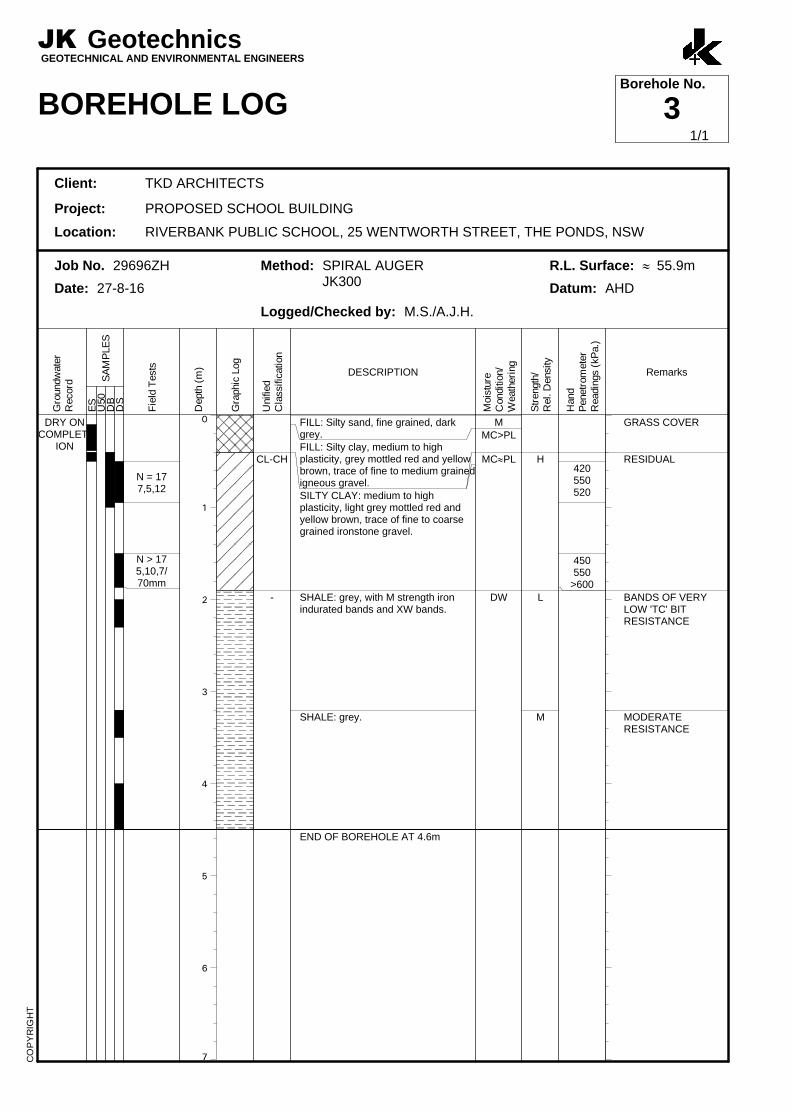
DRY ONCOMPLET-
ION
N = 177,5,12
N > 175,10,7/70mm
CL-CH
-
FILL: Silty sand, fine grained, darkgrey.FILL: Silty clay, medium to highplasticity, grey mottled red and yellowbrown, trace of fine to medium grainedigneous gravel.SILTY CLAY: medium to highplasticity, light grey mottled red andyellow brown, trace of fine to coarsegrained ironstone gravel.
SHALE: grey, with M strength ironindurated bands and XW bands.
SHALE: grey.
END OF BOREHOLE AT 4.6m
MMC>PL
MC»PL
DW
H
L
M
420550520
450550
>600
GRASS COVER
RESIDUAL
BANDS OF VERYLOW 'TC' BITRESISTANCE
MODERATERESISTANCE
JK GeotechnicsGEOTECHNICAL AND ENVIRONMENTAL ENGINEERS
BOREHOLE LOGBorehole No.
3
Client: TKD ARCHITECTS
Project: PROPOSED SCHOOL BUILDING
Location: RIVERBANK PUBLIC SCHOOL, 25 WENTWORTH STREET, THE PONDS, NSW
Job No. 29696ZH Method: SPIRAL AUGERJK300
R.L. Surface: » 55.9m
Date: 27-8-16 Datum: AHD
Logged/Checked by: M.S./A.J.H.
Gro
undw
ate
rR
ecord
ES
SA
MP
LE
SU
50
DB
DS
Fie
ld T
ests
Depth
(m
)
Gra
phic
Log
Unifie
dC
lassific
ation
DESCRIPTION
Mois
ture
Conditio
n/
Weath
eri
ng
Str
ength
/R
el. D
ensity
Hand
Penetr
om
ete
rR
eadin
gs (
kP
a.)
Remarks
CO
PY
RIG
HT
1/1
0
1
2
3
4
5
6
7
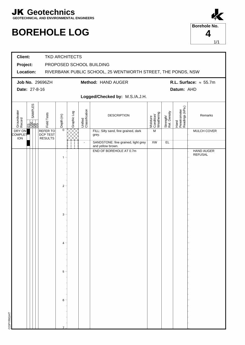
DRY ONCOMPLET-
ION
REFER TODCP TESTRESULTS
-
FILL: Silty sand, fine grained, darkgrey.
SANDSTONE: fine grained, light greyand yellow brown.
END OF BOREHOLE AT 0.7m
M
XW EL
MULCH COVER
HAND AUGERREFUSAL
JK GeotechnicsGEOTECHNICAL AND ENVIRONMENTAL ENGINEERS
BOREHOLE LOGBorehole No.
4
Client: TKD ARCHITECTS
Project: PROPOSED SCHOOL BUILDING
Location: RIVERBANK PUBLIC SCHOOL, 25 WENTWORTH STREET, THE PONDS, NSW
Job No. 29696ZH Method: HAND AUGER R.L. Surface: » 55.7m
Date: 27-8-16 Datum: AHD
Logged/Checked by: M.S./A.J.H.
Gro
undw
ate
rR
ecord
ES
SA
MP
LE
SU
50
DB
DS
Fie
ld T
ests
Depth
(m
)
Gra
phic
Log
Unifie
dC
lassific
ation
DESCRIPTION
Mois
ture
Conditio
n/
Weath
eri
ng
Str
ength
/R
el. D
ensity
Hand
Penetr
om
ete
rR
eadin
gs (
kP
a.)
Remarks
CO
PY
RIG
HT
1/1
0
1
2
3
4
5
6
7
DRY ONCOMPLET-
ION -
FILL: Silty sand, fine grained, darkgrey.
SHALE: grey and brown, with finegrained sandstone seams.
SHALE: grey.
END OF BOREHOLE AT 1.0m
M
XW-DW
DW
EL-VL
M
GRASS COVER
VERY LOW 'TC' BITRESISTANCELOW RESISTANCE
MODERATE TO HIGHRESISTANCE'TC' BIT REFUSAL
JK GeotechnicsGEOTECHNICAL AND ENVIRONMENTAL ENGINEERS
BOREHOLE LOGBorehole No.
5
Client: TKD ARCHITECTS
Project: PROPOSED SCHOOL BUILDING
Location: RIVERBANK PUBLIC SCHOOL, 25 WENTWORTH STREET, THE PONDS, NSW
Job No. 29696ZH Method: SPIRAL AUGERJK300
R.L. Surface: » 56.8m
Date: 27-8-16 Datum: AHD
Logged/Checked by: M.S./A.J.H.
Gro
undw
ate
rR
ecord
ES
SA
MP
LE
SU
50
DB
DS
Fie
ld T
ests
Depth
(m
)
Gra
phic
Log
Unifie
dC
lassific
ation
DESCRIPTION
Mois
ture
Conditio
n/
Weath
eri
ng
Str
ength
/R
el. D
ensity
Hand
Penetr
om
ete
rR
eadin
gs (
kP
a.)
Remarks
CO
PY
RIG
HT
1/1
0
1
2
3
4
5
6
7
DRY ONCOMPLET-
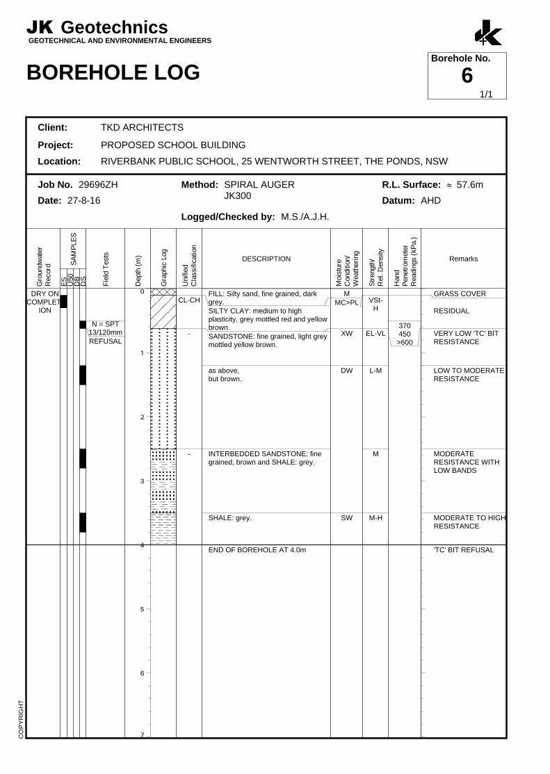
ION
N = SPT13/120mmREFUSAL
CL-CH
-
-
FILL: Silty sand, fine grained, darkgrey.SILTY CLAY: medium to highplasticity, grey mottled red and yellowbrown.SANDSTONE: fine grained, light greymottled yellow brown.
as above,but brown.
INTERBEDDED SANDSTONE: finegrained, brown and SHALE: grey.
SHALE: grey.
END OF BOREHOLE AT 4.0m
MMC>PL
XW
DW
SW
VSt-H
EL-VL
L-M
M
M-H
370450
>600
GRASS COVER
RESIDUAL
VERY LOW 'TC' BITRESISTANCE
LOW TO MODERATERESISTANCE
MODERATERESISTANCE WITHLOW BANDS
MODERATE TO HIGHRESISTANCE
'TC' BIT REFUSAL
JK GeotechnicsGEOTECHNICAL AND ENVIRONMENTAL ENGINEERS
BOREHOLE LOGBorehole No.
6
Client: TKD ARCHITECTS
Project: PROPOSED SCHOOL BUILDING
Location: RIVERBANK PUBLIC SCHOOL, 25 WENTWORTH STREET, THE PONDS, NSW
Job No. 29696ZH Method: SPIRAL AUGERJK300
R.L. Surface: » 57.6m
Date: 27-8-16 Datum: AHD
Logged/Checked by: M.S./A.J.H.
Gro
undw
ate
rR
ecord
ES
SA
MP
LE
SU
50
DB
DS
Fie
ld T
ests
Depth
(m
)
Gra
phic
Log
Unifie
dC
lassific
ation
DESCRIPTION
Mois
ture
Conditio
n/
Weath
eri
ng
Str
ength
/R
el. D
ensity
Hand
Penetr
om
ete
rR
eadin
gs (
kP
a.)
Remarks
CO
PY
RIG
HT
1/1
0
1
2
3
4
5
6
7
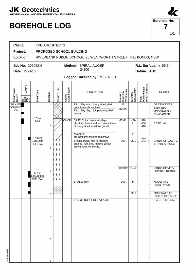
DRY ONCOMPLET-
ION
N = 103,4,6
N = SPT10/150mmREFUSAL
N > 98,9/140mm
REFUSAL
CL-CH
-
FILL: Silty sand, fine grained, darkgrey, trace of clay fines.FILL: Silty clay, high plasticity, darkbrown.
SILTY CLAY: medium to highplasticity, brown and red brown, traceof fine grained ironstone gravel.
as above,but light grey mottled red brown.
SANDSTONE: fine to mediumgrained, light grey mottled yellowbrown, with XW bands.
SHALE: grey.
END OF BOREHOLE AT 4.2m
M
MC>PL
MC»PL
DW
XW-DW
DW
VSt-H
H
VL-L
EL-VL
M
M-H
320450410
410400
GRASS COVER
APPEARSMODERATELYCOMPACTED
RESIDUAL
BANDS OF LOW 'TC'BIT RESISTANCE
BANDS OF VERYLOW RESISTANCE
MODERATERESISTANCE
MODERATE TOHIGH RESISTANCE
'TC' BIT REFUSAL
JK GeotechnicsGEOTECHNICAL AND ENVIRONMENTAL ENGINEERS
BOREHOLE LOGBorehole No.
7
Client: TKD ARCHITECTS
Project: PROPOSED SCHOOL BUILDING
Location: RIVERBANK PUBLIC SCHOOL, 25 WENTWORTH STREET, THE PONDS, NSW
Job No. 29696ZH Method: SPIRAL AUGERJK300
R.L. Surface: » 59.3m
Date: 27-8-16 Datum: AHD
Logged/Checked by: M.S./A.J.H.
Gro
undw
ate
rR
ecord
ES
SA
MP
LE
SU
50
DB
DS
Fie
ld T
ests
Depth
(m
)
Gra
phic
Log
Unifie
dC
lassific
ation
DESCRIPTION
Mois
ture
Conditio
n/
Weath
eri
ng
Str
ength
/R
el. D
ensity
Hand
Penetr
om
ete
rR
eadin
gs (
kP
a.)
Remarks
CO
PY
RIG
HT
1/1
0
1
2
3
4
5
6
7
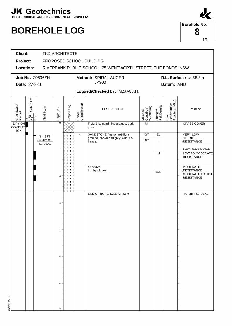
DRY ONCOMPLET-
ION
N = SPT3/20mm
REFUSAL
-
FILL: Silty sand, fine grained, darkgrey.
SANDSTONE fine to me1diumgrained, brown and grey, with XWbands.
as above,but light brown.
END OF BOREHOLE AT 2.6m
M
XW
DW
EL
L
M
M-H
GRASS COVER
VERY LOW'TC' BITRESISTANCE
LOW RESISTANCE
LOW TO MODERATERESISTANCE
MODERATERESISTANCEMODERATE TO HIGHRESISTANCE
'TC' BIT REFUSAL
JK GeotechnicsGEOTECHNICAL AND ENVIRONMENTAL ENGINEERS
BOREHOLE LOGBorehole No.
8
Client: TKD ARCHITECTS
Project: PROPOSED SCHOOL BUILDING
Location: RIVERBANK PUBLIC SCHOOL, 25 WENTWORTH STREET, THE PONDS, NSW
Job No. 29696ZH Method: SPIRAL AUGERJK300
R.L. Surface: » 58.8m
Date: 27-8-16 Datum: AHD
Logged/Checked by: M.S./A.J.H.
Gro
undw
ate
rR
ecord
ES
SA
MP
LE
SU
50
DB
DS
Fie
ld T
ests
Depth
(m
)
Gra
phic
Log
Unifie
dC
lassific
ation
DESCRIPTION
Mois
ture
Conditio
n/
Weath
eri
ng
Str
ength
/R
el. D
ensity
Hand
Penetr
om
ete
rR
eadin
gs (
kP
a.)
Remarks
CO
PY
RIG
HT
1/1
0
1
2
3
4
5
6
7
DRY ONCOMPLET-
ION
N = 124,6,6
N > 91,6,3/10mm
REFUSAL
CL-CH
-
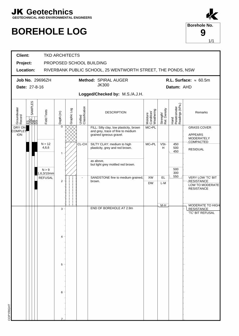
FILL: Silty clay, low plasticity, brownand grey, trace of fine to mediumgrained igneous gravel.
SILTY CLAY: medium to highplasticity, grey and red brown.
as above,but light grey mottled red brown.
SANDSTONE fine to medium grained,brown.
END OF BOREHOLE AT 2.9m
MC>PL
MC»PL
XW
DW
VSt-H
EL
L-M
M-H
450500450
500300550
GRASS COVER
APPEARSMODERATELYCOMPACTED
RESIDUAL
VERY LOW 'TC' BITRESISTANCELOW TO MODERATERESISTANCE
MODERATE TO HIGHRESISTANCE'TC' BIT REFUSAL
JK GeotechnicsGEOTECHNICAL AND ENVIRONMENTAL ENGINEERS
BOREHOLE LOGBorehole No.
9
Client: TKD ARCHITECTS
Project: PROPOSED SCHOOL BUILDING
Location: RIVERBANK PUBLIC SCHOOL, 25 WENTWORTH STREET, THE PONDS, NSW
Job No. 29696ZH Method: SPIRAL AUGERJK300
R.L. Surface: » 60.5m
Date: 27-8-16 Datum: AHD
Logged/Checked by: M.S./A.J.H.
Gro
undw
ate
rR
ecord
ES
SA
MP
LE
SU
50
DB
DS
Fie
ld T
ests
Depth
(m
)
Gra
phic
Log
Unifie
dC
lassific
ation
DESCRIPTION
Mois
ture
Conditio
n/
Weath
eri
ng
Str
ength
/R
el. D
ensity
Hand
Penetr
om
ete
rR
eadin
gs (
kP
a.)
Remarks
CO
PY
RIG
HT
1/1
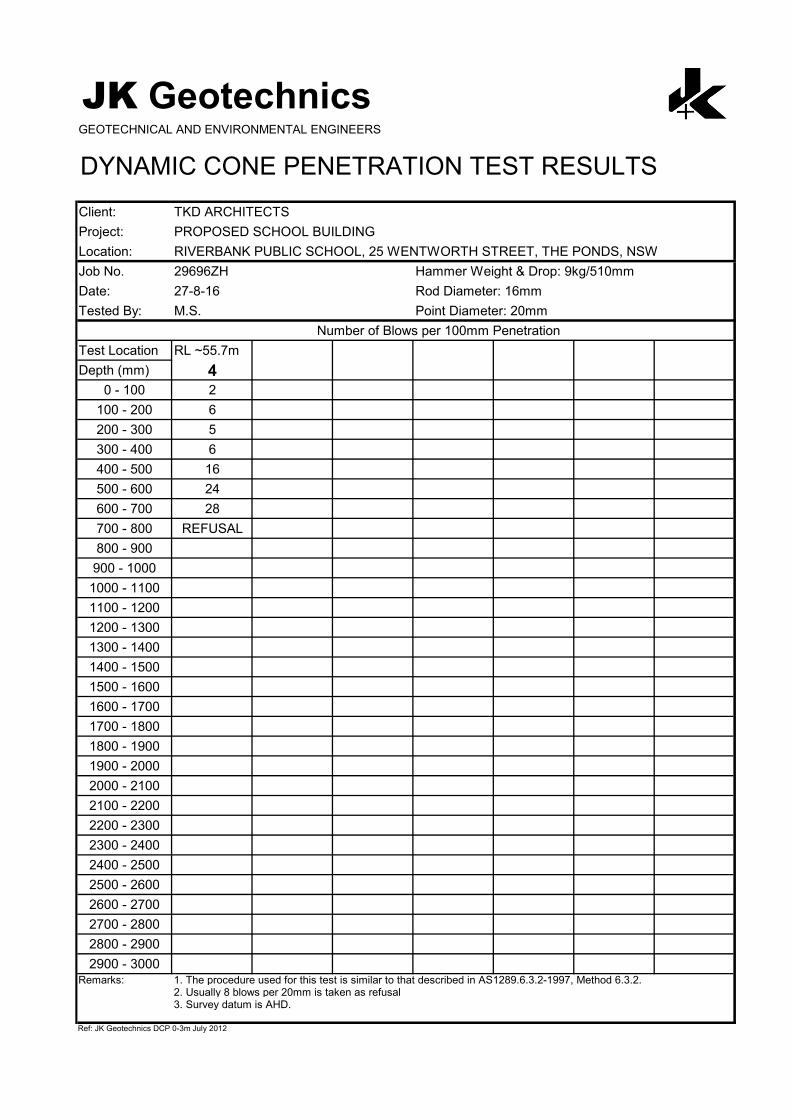
JK GeotechnicsGEOTECHNICAL AND ENVIRONMENTAL ENGINEERS
DYNAMIC CONE PENETRATION TEST RESULTS
Client: TKD ARCHITECTS
Project: PROPOSED SCHOOL BUILDING
Location: RIVERBANK PUBLIC SCHOOL, 25 WENTWORTH STREET, THE PONDS, NSW
Job No. 29696ZH Hammer Weight & Drop: 9kg/510mm
Date: 27-8-16 Rod Diameter: 16mm
Tested By: M.S. Point Diameter: 20mm
Number of Blows per 100mm Penetration
Test Location RL ~55.7m
Depth (mm) 40 - 100 2
100 - 200 6
200 - 300 5
300 - 400 6
400 - 500 16
500 - 600 24
600 - 700 28
700 - 800 REFUSAL
800 - 900
900 - 1000
1000 - 1100
1100 - 1200
1200 - 1300
1300 - 1400
1400 - 1500
1500 - 1600
1600 - 1700
1700 - 1800
1800 - 1900
1900 - 2000
2000 - 2100
2100 - 2200
2200 - 2300
2300 - 2400
2400 - 2500
2500 - 2600
2600 - 2700
2700 - 2800
2800 - 2900
2900 - 3000Remarks: 1. The procedure used for this test is similar to that described in AS1289.6.3.2-1997, Method 6.3.2.
2. Usually 8 blows per 20mm is taken as refusal3. Survey datum is AHD.
Ref: JK Geotechnics DCP 0-3m July 2012
AERIAL IMAGE SOURCE: GOOGLE EARTH PRO 7.1.5.1557
AERIAL IMAGE ©: 2015 GOOGLE INC.
PLO
T D
AT
E: 19/09/2016 11:25:53 A
M D
WG
F
ILE
: S
:\6 G
EO
TE
CH
NIC
AL\6F
G
EO
TE
CH
NIC
AL JO
BS
\29000'S
\29696Z
H T
HE
P
ON
DS
\C
AD
\29696Z
A.D
WG SITE
SITE
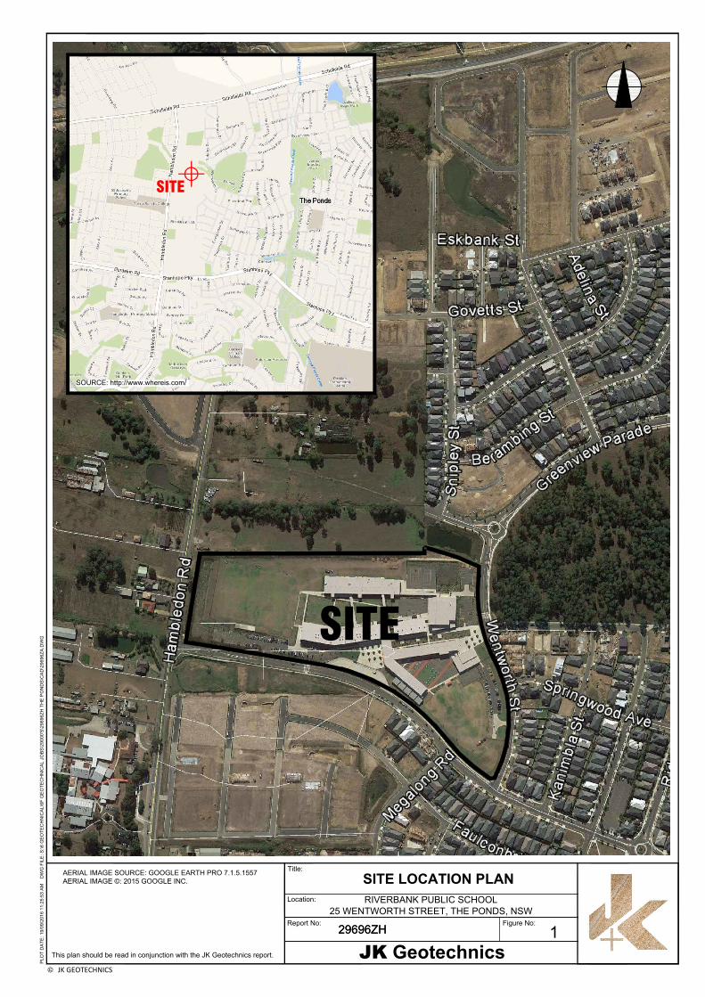
© JK GEOTECHNICS
29696ZH
This plan should be read in conjunction with the JK Geotechnics report.
Report No:
Location:
Title:
RIVERBANK PUBLIC SCHOOL
25 WENTWORTH STREET, THE PONDS, NSW
29696ZH
JK Geotechnics
Figure No:
SITE LOCATION PLAN
1
SOURCE: http://www.whereis.com/
6
0
.
5
6
0
.
0
6
0
.
0
6
0
.
0
6
0
.
0
60.0
6
0
.
0
5
9
.
5
5
9
.
5
5
9
.
5
59.5
59.5
59.5
5
9
.
5
5
9
.
5
5
9
.
0
5
9
.
0
5
9
.
0
5
9
.
0
5
9
.
0
5
9
.
0
5
9
.
0
5
9
.
0
5
8
.
0
58.0
5
8
.
0
5
8
.
0
5
8
.
0
5
8
.
0
5
8
.
0
5
8
.
0
5
8
.
0
5
8
.
0
5
8
.
0
58.0
58.0
5
8
.
0
58.0
5
8
.
0
58.5
5
8
.
5
58.5
5
8
.
5
58.5
5
8
.
5
5
8
.
5
5
8
.
5
5
8
.
5
58.5
5
8
.
5
5
7
.
5
5
7
.
5
5
7
.
5
5
7
.
5
57.5
5
7
.
5
5
7
.
5
5
7
.
5 5
7
.
5
5
7
.
5
5
7
.
5
5
7
.
5
5
7
.
5
57.5
5
7
.
5
5
7
.
5
57.5
5
7
.
5
5
7
.
0
57.0
5
7
.
0
5
7
.
0
57.0
5
7
.
0
5
7
.
0
5
7
.
0
5
7
.
0
5
7
.
0
57.0
5
7
.
0
5
7
.
0
5
7
.
0
5
7
.
0
5
7
.
0
57.0
5
7
.
0
5
6
.
5
56.5
5
6
.
5
56.5
5
6
.
5
5
6
.
5
5
6
.
5
5
6
.
5
5
6
.
5
5
6
.
5
56.5
5
6
.
5
5
6
.
5
5
6
.
5
5
6
.
5
5
6
.
5
5
2
.
5
5
2
.
5
5
2
.
5
53.0
5
3
.
0
5
3
.
0
5
3
.
5
5
3
.
5
5
3
.
5
5
3
.
5
5
4
.
0
5
4
.
0
5
4
.
0
5
4
.
0
5
4
.
5
54.5
5
4
.
5
5
4
.
5
5
4
.
5
54.5
5
4
.
5
5
5
.
0
55.0
5
5
.
0
5
5
.
0
5
5
.
0
55.0
5
5
.
5
55.5
5
5
.
5
5
5
.
5
5
5
.
5
5
5
.
5
5
5
.
5
5
6
.
0
56.0
56.0
5
6
.
0
5
6
.
0
5
6
.
0
5
6
.
0
5
6
.
0
5
6
.
0
5
6
.
0
56.0
5
6
.
0
5
6
.
0
5
6
.
0
5
6
.
0
5
6
.
0
56.0
5
6
.
0
5
5
.
0
55.0
5
5
.
0
55.0
5
5
.
5
5
5
.
5
55.5
5
5
.
5
55.5
5
5
.
5
5
5
.
5
60.5
6
1
.
0
5
5
.
0
5
5
.
0
5
5
.
0
5
5
.
5
5
5
.
5
B37
B34
B33
B32
B14
9
7
8
1
5
2
6
3
2
0
-
2
5
°
1
5
°
1
5
°
2
-
3
°
4
PL
OT
D
AT
E: 1
9/0
9/2
01
6 1
1:2
5:3
8 A
M D
WG
F
IL
E: S
:\6
G
EO
TE
CH
NIC
AL
\6
F G
EO
TE
CH
NIC
AL
JO
BS
\2
90
00
'S
\2
96
96
ZH
T
HE
P
ON
DS
\C
AD
\2
96
96
ZA
.D
WG
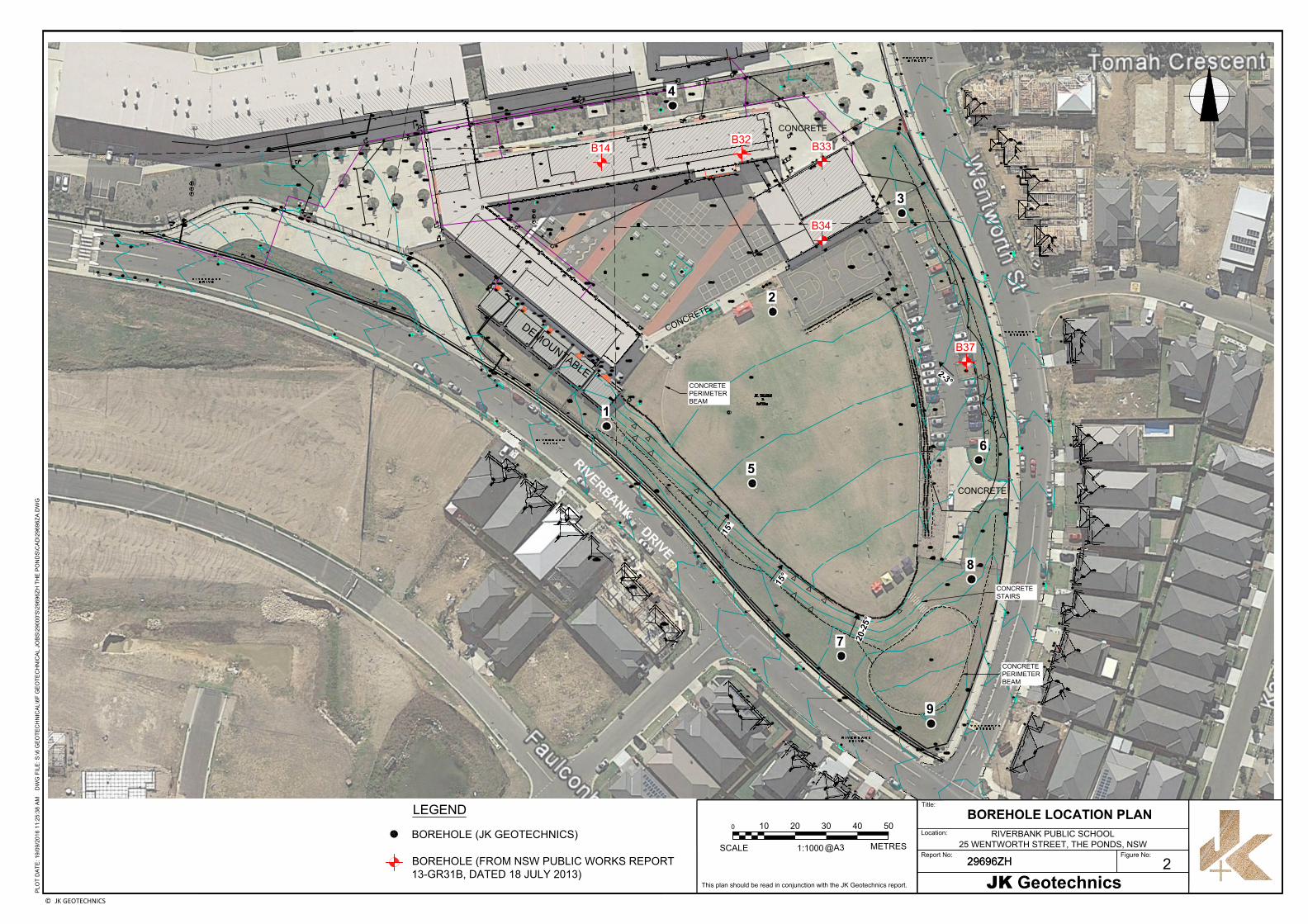
This plan should be read in conjunction with the JK Geotechnics report.
0
SCALE@A3
10 20 30 40 50
1:1000
METRES
Report No:
29696ZH
Location:
Title:
RIVERBANK PUBLIC SCHOOL
25 WENTWORTH STREET, THE PONDS, NSW
29696ZH
JK Geotechnics
© JK GEOTECHNICS
Figure No:
BOREHOLE LOCATION PLAN
2
CONCRETE
STAIRS
R
I
V
E
R
B
A
N
K
D
R
I
V
E
LEGEND
BOREHOLE (JK GEOTECHNICS)
BOREHOLE (FROM NSW PUBLIC WORKS REPORT
13-GR31B, DATED 18 JULY 2013)
D
E
M
O
U
N
T
A
B
L
E
CONCRETE
CONCRETE
C
O
N
C
R
E
T
E
CONCRETE
PERIMETER
BEAM
CONCRETE
PERIMETER
BEAM
115 Wicks Road PO Box 978 T: 61 2 9888 5000 E: [email protected]
Macquarie Park NSW 2113 North Ryde BC NSW 1670 F: 61 2 9888 5001 www.jkgeotechnics.com.au
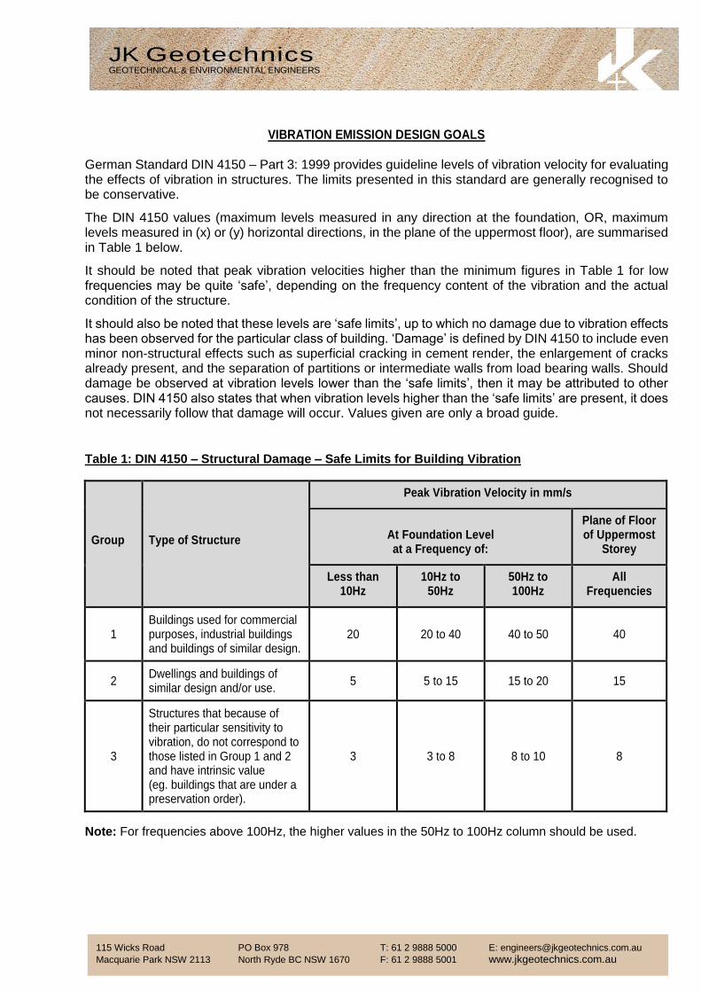
VIBRATION EMISSION DESIGN GOALS German Standard DIN 4150 – Part 3: 1999 provides guideline levels of vibration velocity for evaluating the effects of vibration in structures. The limits presented in this standard are generally recognised to be conservative.
The DIN 4150 values (maximum levels measured in any direction at the foundation, OR, maximum levels measured in (x) or (y) horizontal directions, in the plane of the uppermost floor), are summarised in Table 1 below.
It should be noted that peak vibration velocities higher than the minimum figures in Table 1 for low frequencies may be quite ‘safe’, depending on the frequency content of the vibration and the actual condition of the structure.
It should also be noted that these levels are ‘safe limits’, up to which no damage due to vibration effects has been observed for the particular class of building. ‘Damage’ is defined by DIN 4150 to include even minor non-structural effects such as superficial cracking in cement render, the enlargement of cracks already present, and the separation of partitions or intermediate walls from load bearing walls. Should damage be observed at vibration levels lower than the ‘safe limits’, then it may be attributed to other causes. DIN 4150 also states that when vibration levels higher than the ‘safe limits’ are present, it does not necessarily follow that damage will occur. Values given are only a broad guide.
Table 1: DIN 4150 – Structural Damage – Safe Limits for Building Vibration
Group Type of Structure
Peak Vibration Velocity in mm/s
At Foundation Level at a Frequency of:
Plane of Floor of Uppermost
Storey
Less than 10Hz
10Hz to 50Hz
50Hz to 100Hz
All Frequencies
1 Buildings used for commercial purposes, industrial buildings and buildings of similar design.
20 20 to 40 40 to 50 40
2 Dwellings and buildings of similar design and/or use.
5 5 to 15 15 to 20 15
3
Structures that because of their particular sensitivity to vibration, do not correspond to those listed in Group 1 and 2 and have intrinsic value (eg. buildings that are under a preservation order).
3 3 to 8 8 to 10 8
Note: For frequencies above 100Hz, the higher values in the 50Hz to 100Hz column should be used.
JK Geotechnics GEOTECHNICAL & ENVIRONMENTAL ENGINEERS
Jeffery & Katauskas Pty Ltd, trading as JK Geotechnics ABN 17 003 550 801
JKG Report Explanation Notes Rev2 May 2013 Page 1 of 4
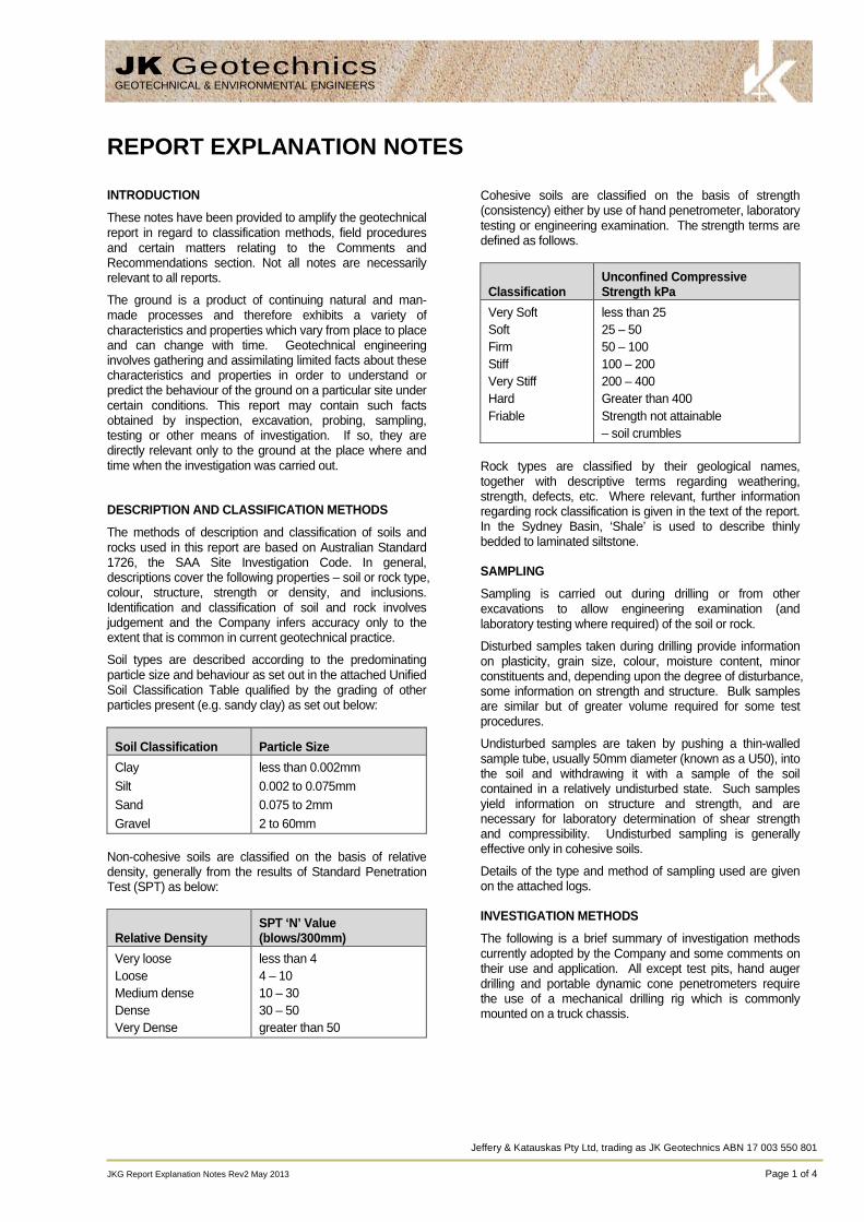
REPORT EXPLANATION NOTES
INTRODUCTION
These notes have been provided to amplify the geotechnicalreport in regard to classification methods, field proceduresand certain matters relating to the Comments andRecommendations section. Not all notes are necessarilyrelevant to all reports.
The ground is a product of continuing natural and man-made processes and therefore exhibits a variety ofcharacteristics and properties which vary from place to placeand can change with time. Geotechnical engineeringinvolves gathering and assimilating limited facts about thesecharacteristics and properties in order to understand orpredict the behaviour of the ground on a particular site undercertain conditions. This report may contain such factsobtained by inspection, excavation, probing, sampling,testing or other means of investigation. If so, they aredirectly relevant only to the ground at the place where andtime when the investigation was carried out.
DESCRIPTION AND CLASSIFICATION METHODS
The methods of description and classification of soils androcks used in this report are based on Australian Standard1726, the SAA Site Investigation Code. In general,descriptions cover the following properties – soil or rock type,colour, structure, strength or density, and inclusions.Identification and classification of soil and rock involvesjudgement and the Company infers accuracy only to theextent that is common in current geotechnical practice.
Soil types are described according to the predominatingparticle size and behaviour as set out in the attached UnifiedSoil Classification Table qualified by the grading of otherparticles present (e.g. sandy clay) as set out below:
Soil Classification Particle Size
Clay
Silt
Sand
Gravel
less than 0.002mm
0.002 to 0.075mm
0.075 to 2mm
2 to 60mm
Non-cohesive soils are classified on the basis of relativedensity, generally from the results of Standard PenetrationTest (SPT) as below:
Relative DensitySPT ‘N’ Value(blows/300mm)
Very loose
Loose
Medium dense
Dense
Very Dense
less than 4
4 – 10
10 – 30
30 – 50
greater than 50
Cohesive soils are classified on the basis of strength(consistency) either by use of hand penetrometer, laboratorytesting or engineering examination. The strength terms aredefined as follows.
ClassificationUnconfined CompressiveStrength kPa
Very Soft
Soft
Firm
Stiff
Very Stiff
Hard
Friable
less than 25
25 – 50
50 – 100
100 – 200
200 – 400
Greater than 400
Strength not attainable
– soil crumbles
Rock types are classified by their geological names,together with descriptive terms regarding weathering,strength, defects, etc. Where relevant, further informationregarding rock classification is given in the text of the report.In the Sydney Basin, ‘Shale’ is used to describe thinlybedded to laminated siltstone.
SAMPLING
Sampling is carried out during drilling or from otherexcavations to allow engineering examination (andlaboratory testing where required) of the soil or rock.
Disturbed samples taken during drilling provide informationon plasticity, grain size, colour, moisture content, minorconstituents and, depending upon the degree of disturbance,some information on strength and structure. Bulk samplesare similar but of greater volume required for some testprocedures.
Undisturbed samples are taken by pushing a thin-walledsample tube, usually 50mm diameter (known as a U50), intothe soil and withdrawing it with a sample of the soilcontained in a relatively undisturbed state. Such samplesyield information on structure and strength, and arenecessary for laboratory determination of shear strengthand compressibility. Undisturbed sampling is generallyeffective only in cohesive soils.
Details of the type and method of sampling used are givenon the attached logs.
INVESTIGATION METHODS
The following is a brief summary of investigation methodscurrently adopted by the Company and some comments ontheir use and application. All except test pits, hand augerdrilling and portable dynamic cone penetrometers requirethe use of a mechanical drilling rig which is commonlymounted on a truck chassis.
JK GeotechnicsGEOTECHNICAL & ENVIRONMENTAL ENGINEERS
JKG Report Explanation Notes Rev2 May 2013 Page 2 of 4
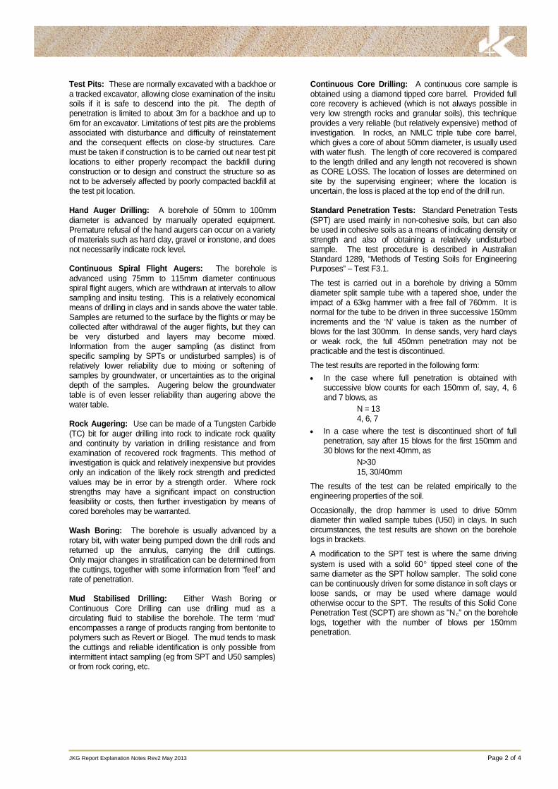
Test Pits: These are normally excavated with a backhoe ora tracked excavator, allowing close examination of the insitusoils if it is safe to descend into the pit. The depth ofpenetration is limited to about 3m for a backhoe and up to6m for an excavator. Limitations of test pits are the problemsassociated with disturbance and difficulty of reinstatementand the consequent effects on close-by structures. Caremust be taken if construction is to be carried out near test pitlocations to either properly recompact the backfill duringconstruction or to design and construct the structure so asnot to be adversely affected by poorly compacted backfill atthe test pit location.
Hand Auger Drilling: A borehole of 50mm to 100mmdiameter is advanced by manually operated equipment.Premature refusal of the hand augers can occur on a varietyof materials such as hard clay, gravel or ironstone, and doesnot necessarily indicate rock level.
Continuous Spiral Flight Augers: The borehole isadvanced using 75mm to 115mm diameter continuousspiral flight augers, which are withdrawn at intervals to allowsampling and insitu testing. This is a relatively economicalmeans of drilling in clays and in sands above the water table.Samples are returned to the surface by the flights or may becollected after withdrawal of the auger flights, but they canbe very disturbed and layers may become mixed.Information from the auger sampling (as distinct fromspecific sampling by SPTs or undisturbed samples) is ofrelatively lower reliability due to mixing or softening ofsamples by groundwater, or uncertainties as to the originaldepth of the samples. Augering below the groundwatertable is of even lesser reliability than augering above thewater table.
Rock Augering: Use can be made of a Tungsten Carbide(TC) bit for auger drilling into rock to indicate rock qualityand continuity by variation in drilling resistance and fromexamination of recovered rock fragments. This method ofinvestigation is quick and relatively inexpensive but providesonly an indication of the likely rock strength and predictedvalues may be in error by a strength order. Where rockstrengths may have a significant impact on constructionfeasibility or costs, then further investigation by means ofcored boreholes may be warranted.
Wash Boring: The borehole is usually advanced by arotary bit, with water being pumped down the drill rods andreturned up the annulus, carrying the drill cuttings.Only major changes in stratification can be determined fromthe cuttings, together with some information from “feel” andrate of penetration.
Mud Stabilised Drilling: Either Wash Boring orContinuous Core Drilling can use drilling mud as acirculating fluid to stabilise the borehole. The term ‘mud’encompasses a range of products ranging from bentonite topolymers such as Revert or Biogel. The mud tends to maskthe cuttings and reliable identification is only possible fromintermittent intact sampling (eg from SPT and U50 samples)or from rock coring, etc.
Continuous Core Drilling: A continuous core sample isobtained using a diamond tipped core barrel. Provided fullcore recovery is achieved (which is not always possible invery low strength rocks and granular soils), this techniqueprovides a very reliable (but relatively expensive) method ofinvestigation. In rocks, an NMLC triple tube core barrel,which gives a core of about 50mm diameter, is usually usedwith water flush. The length of core recovered is comparedto the length drilled and any length not recovered is shownas CORE LOSS. The location of losses are determined onsite by the supervising engineer; where the location isuncertain, the loss is placed at the top end of the drill run.
Standard Penetration Tests: Standard Penetration Tests(SPT) are used mainly in non-cohesive soils, but can alsobe used in cohesive soils as a means of indicating density orstrength and also of obtaining a relatively undisturbedsample. The test procedure is described in AustralianStandard 1289, “Methods of Testing Soils for EngineeringPurposes” – Test F3.1.
The test is carried out in a borehole by driving a 50mmdiameter split sample tube with a tapered shoe, under theimpact of a 63kg hammer with a free fall of 760mm. It isnormal for the tube to be driven in three successive 150mmincrements and the ‘N’ value is taken as the number ofblows for the last 300mm. In dense sands, very hard claysor weak rock, the full 450mm penetration may not bepracticable and the test is discontinued.
The test results are reported in the following form:
In the case where full penetration is obtained withsuccessive blow counts for each 150mm of, say, 4, 6and 7 blows, as
N = 134, 6, 7
In a case where the test is discontinued short of fullpenetration, say after 15 blows for the first 150mm and30 blows for the next 40mm, as
N>3015, 30/40mm
The results of the test can be related empirically to theengineering properties of the soil.
Occasionally, the drop hammer is used to drive 50mmdiameter thin walled sample tubes (U50) in clays. In suchcircumstances, the test results are shown on the boreholelogs in brackets.
A modification to the SPT test is where the same drivingsystem is used with a solid 60 tipped steel cone of thesame diameter as the SPT hollow sampler. The solid conecan be continuously driven for some distance in soft clays orloose sands, or may be used where damage wouldotherwise occur to the SPT. The results of this Solid ConePenetration Test (SCPT) are shown as "N c” on the boreholelogs, together with the number of blows per 150mmpenetration.
JKG Report Explanation Notes Rev2 May 2013 Page 3 of 4
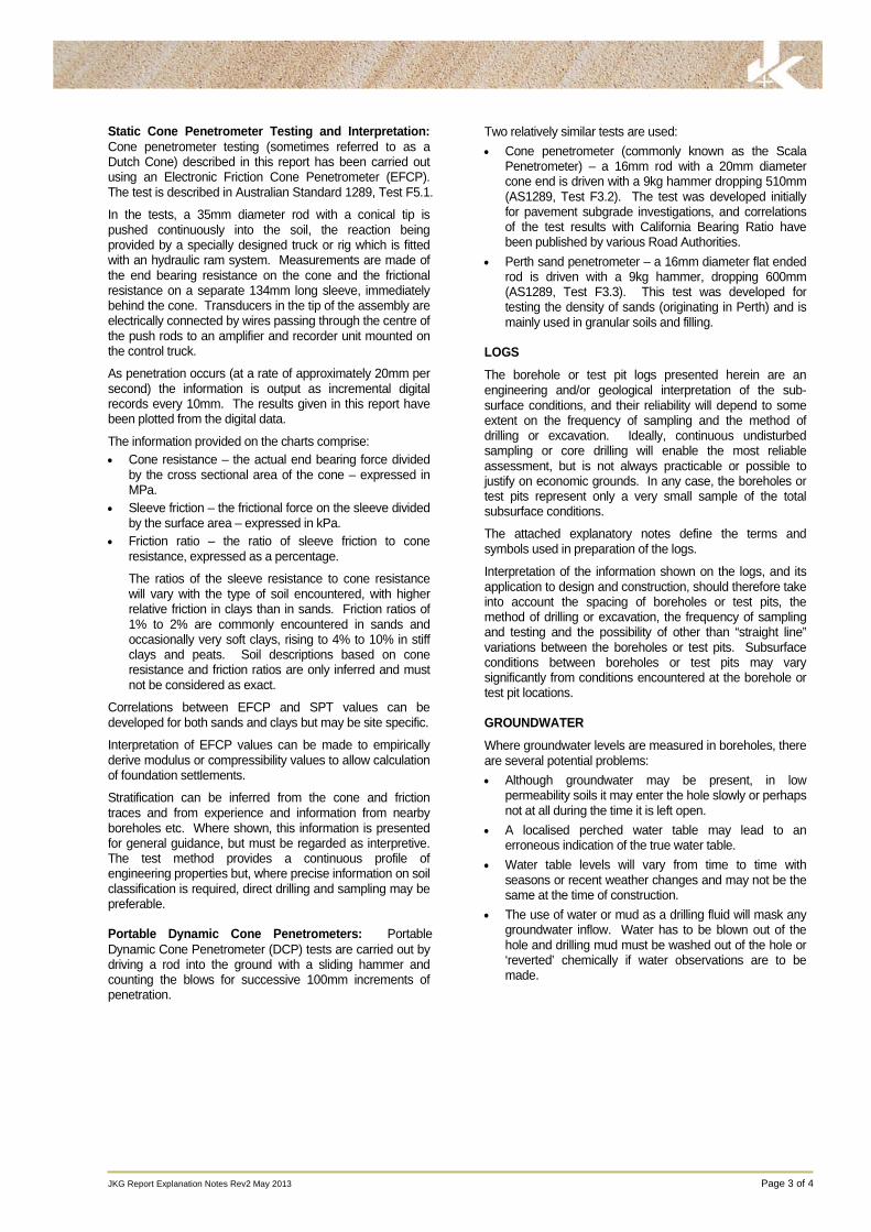
Static Cone Penetrometer Testing and Interpretation:Cone penetrometer testing (sometimes referred to as aDutch Cone) described in this report has been carried outusing an Electronic Friction Cone Penetrometer (EFCP).The test is described in Australian Standard 1289, Test F5.1.
In the tests, a 35mm diameter rod with a conical tip ispushed continuously into the soil, the reaction beingprovided by a specially designed truck or rig which is fittedwith an hydraulic ram system. Measurements are made ofthe end bearing resistance on the cone and the frictionalresistance on a separate 134mm long sleeve, immediatelybehind the cone. Transducers in the tip of the assembly areelectrically connected by wires passing through the centre ofthe push rods to an amplifier and recorder unit mounted onthe control truck.
As penetration occurs (at a rate of approximately 20mm persecond) the information is output as incremental digitalrecords every 10mm. The results given in this report havebeen plotted from the digital data.
The information provided on the charts comprise:
Cone resistance – the actual end bearing force dividedby the cross sectional area of the cone – expressed inMPa.
Sleeve friction – the frictional force on the sleeve dividedby the surface area – expressed in kPa.
Friction ratio – the ratio of sleeve friction to coneresistance, expressed as a percentage.
The ratios of the sleeve resistance to cone resistancewill vary with the type of soil encountered, with higherrelative friction in clays than in sands. Friction ratios of1% to 2% are commonly encountered in sands andoccasionally very soft clays, rising to 4% to 10% in stiffclays and peats. Soil descriptions based on coneresistance and friction ratios are only inferred and mustnot be considered as exact.
Correlations between EFCP and SPT values can bedeveloped for both sands and clays but may be site specific.
Interpretation of EFCP values can be made to empiricallyderive modulus or compressibility values to allow calculationof foundation settlements.
Stratification can be inferred from the cone and frictiontraces and from experience and information from nearbyboreholes etc. Where shown, this information is presentedfor general guidance, but must be regarded as interpretive.The test method provides a continuous profile ofengineering properties but, where precise information on soilclassification is required, direct drilling and sampling may bepreferable.
Portable Dynamic Cone Penetrometers: PortableDynamic Cone Penetrometer (DCP) tests are carried out bydriving a rod into the ground with a sliding hammer andcounting the blows for successive 100mm increments ofpenetration.
Two relatively similar tests are used:
Cone penetrometer (commonly known as the ScalaPenetrometer) – a 16mm rod with a 20mm diametercone end is driven with a 9kg hammer dropping 510mm(AS1289, Test F3.2). The test was developed initiallyfor pavement subgrade investigations, and correlationsof the test results with California Bearing Ratio havebeen published by various Road Authorities.
Perth sand penetrometer – a 16mm diameter flat endedrod is driven with a 9kg hammer, dropping 600mm(AS1289, Test F3.3). This test was developed fortesting the density of sands (originating in Perth) and ismainly used in granular soils and filling.
LOGS
The borehole or test pit logs presented herein are anengineering and/or geological interpretation of the sub-surface conditions, and their reliability will depend to someextent on the frequency of sampling and the method ofdrilling or excavation. Ideally, continuous undisturbedsampling or core drilling will enable the most reliableassessment, but is not always practicable or possible tojustify on economic grounds. In any case, the boreholes ortest pits represent only a very small sample of the totalsubsurface conditions.
The attached explanatory notes define the terms andsymbols used in preparation of the logs.
Interpretation of the information shown on the logs, and itsapplication to design and construction, should therefore takeinto account the spacing of boreholes or test pits, themethod of drilling or excavation, the frequency of samplingand testing and the possibility of other than “straight line”variations between the boreholes or test pits. Subsurfaceconditions between boreholes or test pits may varysignificantly from conditions encountered at the borehole ortest pit locations.
GROUNDWATER
Where groundwater levels are measured in boreholes, thereare several potential problems:
Although groundwater may be present, in lowpermeability soils it may enter the hole slowly or perhapsnot at all during the time it is left open.
A localised perched water table may lead to anerroneous indication of the true water table.
Water table levels will vary from time to time withseasons or recent weather changes and may not be thesame at the time of construction.
The use of water or mud as a drilling fluid will mask anygroundwater inflow. Water has to be blown out of thehole and drilling mud must be washed out of the hole or‘reverted’ chemically if water observations are to bemade.

JKG Report Explanation Notes Rev2 May 2013 Page 4 of 4
More reliable measurements can be made by installingstandpipes which are read after stabilising at intervalsranging from several days to perhaps weeks for lowpermeability soils. Piezometers, sealed in a particularstratum, may be advisable in low permeability soils or wherethere may be interference from perched water tables orsurface water.
FILL
The presence of fill materials can often be determined onlyby the inclusion of foreign objects (eg bricks, steel etc) or bydistinctly unusual colour, texture or fabric. Identification ofthe extent of fill materials will also depend on investigationmethods and frequency. Where natural soils similar tothose at the site are used for fill, it may be difficult withlimited testing and sampling to reliably determine the extentof the fill.
The presence of fill materials is usually regarded withcaution as the possible variation in density, strength andmaterial type is much greater than with natural soil deposits.Consequently, there is an increased risk of adverseengineering characteristics or behaviour. If the volume andquality of fill is of importance to a project, then frequent testpit excavations are preferable to boreholes.
LABORATORY TESTING
Laboratory testing is normally carried out in accordance withAustralian Standard 1289 ‘Methods of Testing Soil forEngineering Purposes’. Details of the test procedure usedare given on the individual report forms.
ENGINEERING REPORTS
Engineering reports are prepared by qualified personnel andare based on the information obtained and on currentengineering standards of interpretation and analysis. Wherethe report has been prepared for a specific design proposal(eg. a three storey building) the information andinterpretation may not be relevant if the design proposal ischanged (eg to a twenty storey building). If this happens,the company will be pleased to review the report and thesufficiency of the investigation work.
Every care is taken with the report as it relates tointerpretation of subsurface conditions, discussion ofgeotechnical aspects and recommendations or suggestionsfor design and construction. However, the Company cannotalways anticipate or assume responsibility for:
Unexpected variations in ground conditions – thepotential for this will be partially dependent on boreholespacing and sampling frequency as well as investigationtechnique.
Changes in policy or interpretation of policy by statutoryauthorities.
The actions of persons or contractors responding tocommercial pressures.
If these occur, the company will be pleased to assist withinvestigation or advice to resolve any problems occurring.
SITE ANOMALIES
In the event that conditions encountered on site duringconstruction appear to vary from those which were expectedfrom the information contained in the report, the companyrequests that it immediately be notified. Most problems aremuch more readily resolved when conditions are exposedthat at some later stage, well after the event.
REPRODUCTION OF INFORMATION FORCONTRACTUAL PURPOSES
Attention is drawn to the document ‘Guidelines for theProvision of Geotechnical Information in Tender Documents’ ,published by the Institution of Engineers, Australia. Whereinformation obtained from this investigation is provided fortendering purposes, it is recommended that all information,including the written report and discussion, be madeavailable. In circumstances where the discussion orcomments section is not relevant to the contractual situation,it may be appropriate to prepare a specially editeddocument. The company would be pleased to assist in thisregard and/or to make additional report copies available forcontract purposes at a nominal charge.
Copyright in all documents (such as drawings, borehole ortest pit logs, reports and specifications) provided by theCompany shall remain the property of Jeffery andKatauskas Pty Ltd. Subject to the payment of all fees due,the Client alone shall have a licence to use the documentsprovided for the sole purpose of completing the project towhich they relate. License to use the documents may berevoked without notice if the Client is in breach of anyobjection to make a payment to us.
REVIEW OF DESIGN
Where major civil or structural developments are proposedor where only a limited investigation has been completed orwhere the geotechnical conditions/ constraints are quitecomplex, it is prudent to have a joint design review whichinvolves a senior geotechnical engineer.
SITE INSPECTION
The company will always be pleased to provide engineeringinspection services for geotechnical aspects of work towhich this report is related.
Requirements could range from:
i) a site visit to confirm that conditions exposed are noworse than those interpreted, to
ii) a visit to assist the contractor or other site personnel inidentifying various soil/rock types such as appropriatefooting or pier founding depths, or
iii) full time engineering presence on site.
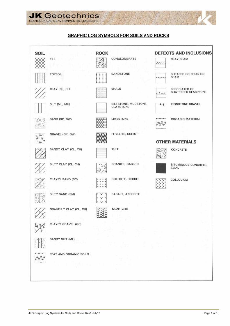
JKG Graph
GEOTEC
hic Log Symbols fo
HNICAL & ENVI
or Soils and Rock
GRAPHI
RONMENTAL E
s Rev1 July12
IC LOG SY
NGINEERS
MBOLS FOOR SOILS AAND ROCKSKS
Pag
ge 1 of 1
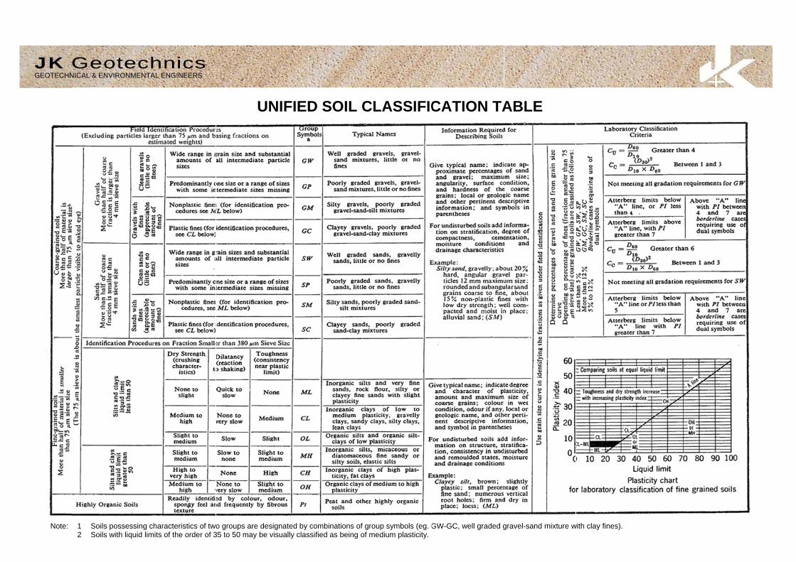
JK GEOTECHN
Note:
GeotecNICAL & ENVIRONMEN
1 Soils possessing2 Soils with liquid
chnics NTAL ENGINEERS
g characteristics of twolimits of the order of 3
UNIF
o groups are designat35 to 50 may be visual
FIED SOIL
ted by combinations olly classified as being
CLASSIFIC
of group symbols (eg. Gof medium plasticity.
CATION TA
GW-GC, well graded g
ABLE
gravel-sand mixture wwith clay fines).
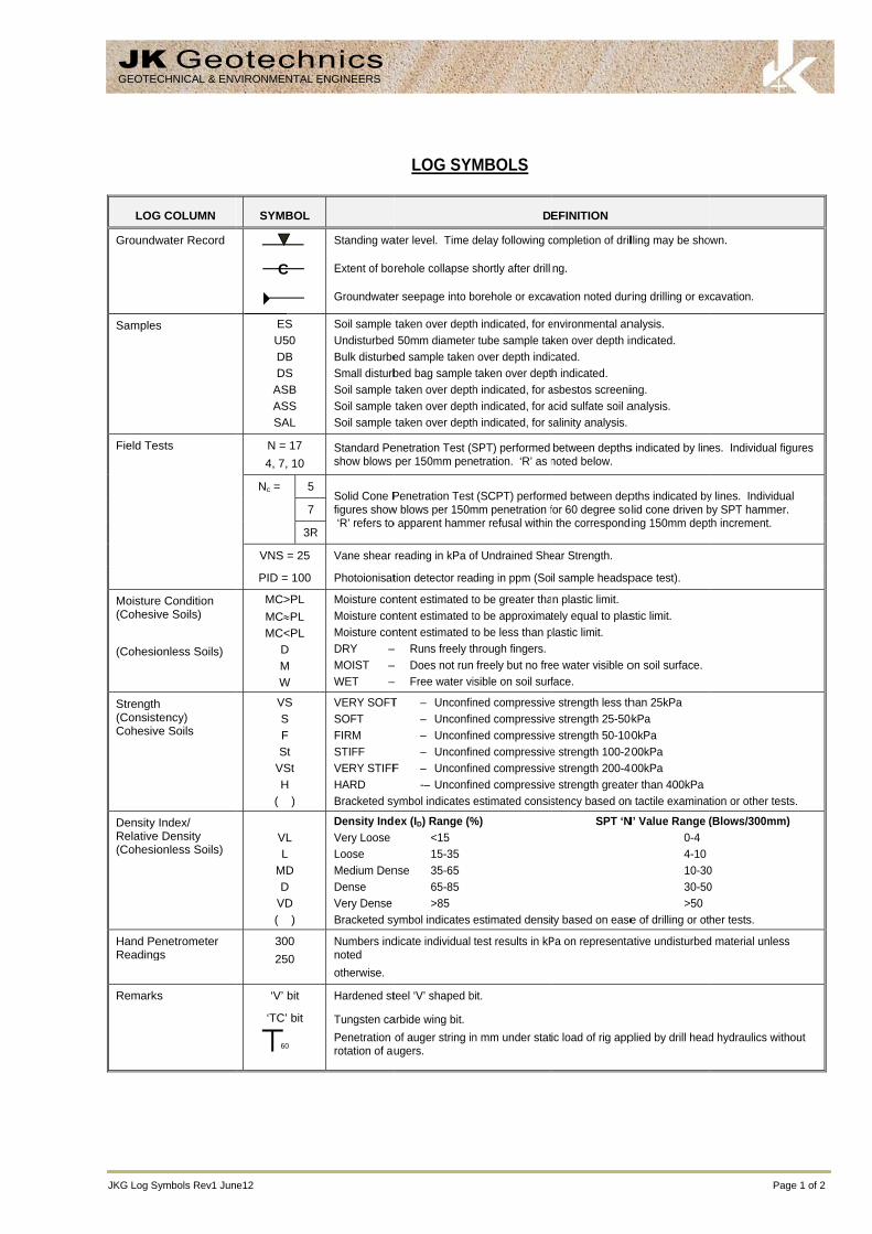
JKG Log S
LOG
Groundw
Samples
Field Te
Moisture(Cohesiv (Cohesio
Strength(ConsistCohesiv
Density Relative(Cohesio
Hand PeReading
Remarks
GEOTEC
ymbols Rev1 Jun
G COLUMN
water Record
s
ests
e Condition ve Soils)
onless Soils)
h tency)
ve Soils
Index/ e Density onless Soils)
enetrometer gs
s
CHNICAL & ENV
e12
SYMBOL
ES U50 DB DS
ASB ASS SAL
N = 17 4, 7, 10
Nc = 5
7
3R
VNS = 25
PID = 100
MC>PL MC≈PL MC<PL
D M W
VS S F St
VSt H
( )
VL L
MD D
VD ( )
300 250
‘V’ bit
‘TC’ bit
60
VIRONMENTAL
C
4
Standing wa
Extent of bo
Groundwate
Soil sample Undisturbed Bulk disturbeSmall disturbSoil sample Soil sample Soil sample
Standard Peshow blows
Solid Cone Pfigures show ‘R’ refers to
R
Vane shear
Photoionisat
Moisture conMoisture conMoisture conDRY –MOIST –WET –
VERY SOFTSOFTFIRMSTIFFVERY STIFFHARDBracketed sy
Density IndVery LooseLooseMedium DenDenseVery DenseBracketed sy
Numbers indnoted otherwise.
Hardened st
Tungsten caPenetration rotation of au
ENGINEERS
LOG SYM
ater level. Time d
rehole collapse s
er seepage into b
taken over depth 50mm diametered sample takenbed bag sample taken over depthtaken over depthtaken over depth
enetration Test (Sper 150mm pen
Penetration Testw blows per 150mo apparent hamm
reading in kPa o
tion detector rea
ntent estimated tntent estimated tntent estimated t
– Runs freely t– Does not run– Free water vi
T – Unconfin – Unconfin – Unconfin – Unconfin
F – Unconfin -– Unconfin
ymbol indicates
ex (ID) Range (%<1515-35
nse 35-6565-85>85
ymbol indicates
dicate individual
teel ‘V’ shaped b
arbide wing bit. of auger string inugers.
MBOLS
D
delay following c
shortly after drilli
borehole or exca
h indicated, for er tube sample ta
n over depth indictaken over dept
h indicated, for ah indicated, for ah indicated, for s
SPT) performed etration. ‘R’ as n
t (SCPT) performmm penetration fmer refusal within
of Undrained She
ding in ppm (So
to be greater thato be approximatto be less than phrough fingers. freely but no freisible on soil surf
ned compressivened compressivened compressivened compressivened compressivened compressiveestimated consis
%)
estimated densit
test results in kP
bit.
n mm under stat
EFINITION
completion of dril
ng.
vation noted dur
environmental anken over depth incated. h indicated.
asbestos screeniacid sulfate soil asalinity analysis.
between depthsnoted below.
med between depfor 60 degree son the correspond
ear Strength.
il sample headsp
n plastic limit. tely equal to plas
plastic limit.
ee water visible oface.
e strength less the strength 25-50e strength 50-10e strength 100-2e strength 200-4e strength greatestency based on
SPT ‘N
ty based on ease
Pa on representa
ic load of rig app
lling may be sho
ring drilling or ex
nalysis. ndicated.
ing. analysis.
s indicated by lin
pths indicated byolid cone driven bing 150mm dept
pace test).
stic limit.
on soil surface.
han 25kPa 0kPa 00kPa 200kPa 400kPa er than 400kPa n tactile examina
N’ Value Range ( 0-4 4-10 10-30 30-50 >50
e of drilling or ot
ative undisturbed
plied by drill head
Pag
own.
xcavation.
es. Individual fig
y lines. Individuaby SPT hammer.th increment.
tion or other test
(Blows/300mm)
0 0
her tests.
d material unless
d hydraulics with
ge 1 of 2
gures
al .
ts.
)
s
hout

JKG Log Symbols Rev
ROCK M
Residual
Extremel
Distinctly
Slightly w
Fresh roc
ROCK SRock strenbedding. Abstract V
TE
Extremel
------------
Very Low
------------
Low:
------------
Medium
------------
High:
------------
Very Hig
------------
Extremel
ABBRE
ABBR
v1 June12
MATERIAL W
TERM
l Soil
ly weathered roc
y weathered rock
weathered rock
ck
STRENGTH ngth is defined bThe test proc
Volume 22, No 2,
ERM SY
ly Low:
------------
w:
------------
------------
Strength:
------------
------------
h:
------------
ly High:
----
----
----
----
-----
-----
EVIATIONS U
REVIATION
Be CS J P
Un S R IS
XWS Cr 60t
WEATHERIN
SYMBO
RS
ck XW
k DW
SW
FR
by the Point Loacedure is desc 1985.
YMBOL Is (5
EL
-----------
VL
-----------
L
-----------
M
-----------
H
-----------
VH
-----------
EH
USED IN DE
DES
Bedding Plane Clay Seam Joint Planar Undulating Smooth Rough Ironstained Extremely WeaCrushed Seam Thickness of de
LO
NG CLASSIF
OL
Soil develoevident; th
Rock is weremoulded
Rock strenironstainingweathering
Rock is slig
Rock show
d Strength Indexribed by the
50) MPa
0.03
0.1
0.3
1
3
10
Eas May A pieknife
A piewith A piescra
A pieone
A pieRing
EFECT DESC
SCRIPTION
Parting
thered Seam
efect in millimetre
OG SYMBOL
FICATION
oped on extremelyhere is a large cha
eathered to such , in water.
ngth usually chang. Porosity mayg products in pore
ghtly discoloured
ws no sign of deco
x (Is 50) and refInternational Jo
ily remoulded by
y be crumbled in t
ece of core 150me. Sharp edges o
ece of core 150m knife.
ece of core 150matched or scored w
ece of core 150mblow. Cannot be
ece of core 150mgs when struck wi
CRIPTION
es
Defec(ie re
LS continue
D
y weathered rockange in volume bu
an extent that it
nged by weathery be increased bes.
but shows little or
omposition or stain
fers to the strengournal of Rock
hand to a materia
he hand. Sandst
mm long x 50mm dof core may be fria
mm long x 50mm d
mm long x 50mm dwith knife; rock ri
mm long x 50mm de scratched with p
mm long x 50mm dith a hammer.
ct orientations melative to horizont
d
DEFINITION
k; the mass strucut the soil has not
has “soil” proper
ring. The rock y leaching, or m
r no change of str
ning.
gth of the rock sk Mechanics, M
FIELD GUIDE
al with soil propert
one is “sugary” an
dia. may be brokeable and break du
dia. can be broken
dia. core cannot bngs under hamme
dia. may be brokeen knife; rock rin
dia. is very difficul
NOT
measured relativetal for vertical ho
cture and substant been significantl
rties, ie it either d
may be highly dmay be decreased
rength from fresh
substance in theMining, Science
E
ties.
nd friable.
en by hand and eauring handling.
n by hand with dif
be broken by hander.
en with hand-held ngs under hamme
lt to break with ha
TES
e to the normal oles)
Page
nce fabric are no y transported.
disintegrates or c
discoloured, usuad due to deposit
rock.
direction normae and Geomec
asily scored with a
fficulty. Readily s
d, can be slightly
pick after more ther.
and-held hammer.
to the long core
2 of 2
longer
can be
ally by tion of
al to the chanics.
a
cored
han
.
e axis
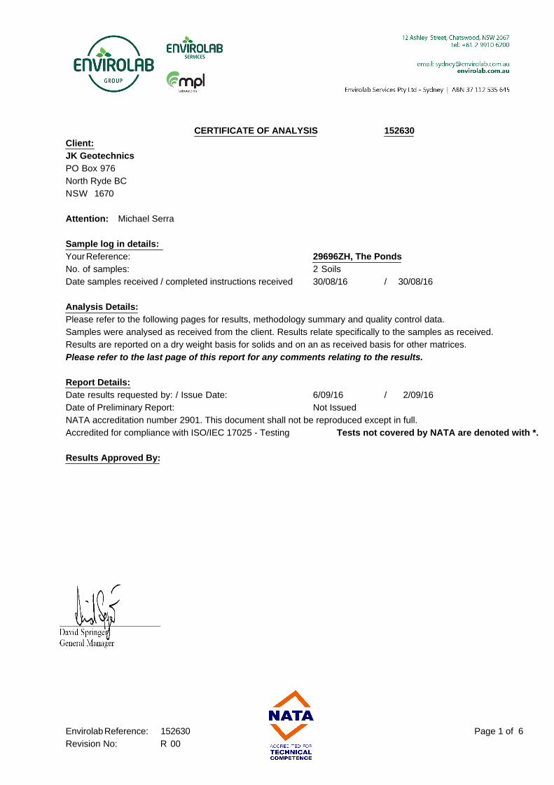
CERTIFICATE OF ANALYSIS 152630
Client:
JK Geotechnics
PO Box 976
North Ryde BC
NSW 1670
Attention: Michael Serra
Sample log in details:
Your Reference: 29696ZH, The Ponds
No. of samples: 2 Soils
Date samples received / completed instructions received 30/08/16 / 30/08/16
Analysis Details:
Please refer to the following pages for results, methodology summary and quality control data.
Samples were analysed as received from the client. Results relate specifically to the samples as received.
Results are reported on a dry weight basis for solids and on an as received basis for other matrices.
Please refer to the last page of this report for any comments relating to the results.
Report Details:
Date results requested by: / Issue Date: 6/09/16 / 2/09/16
Date of Preliminary Report: Not Issued
NATA accreditation number 2901. This document shall not be reproduced except in full.
Accredited for compliance with ISO/IEC 17025 - Testing Tests not covered by NATA are denoted with *.
Results Approved By:
Page 1 of 6Envirolab Reference: 152630
Revision No: R 00

Client Reference: 29696ZH, The Ponds
Misc Inorg - Soil
Our Reference: UNITS 152630-1 152630-2
Your Reference ------------
-
BH1 BH2
Depth ------------ 0.5-1.65 0.5-0.52
Date Sampled
Type of sample
27/08/2016
Soil
27/08/2016
Soil
Date prepared - 31/08/2016 31/08/2016
Date analysed - 31/08/2016 31/08/2016
pH 1:5 soil:water pH Units 5.3 8.8
Sulphate, SO4 1:5 soil:water mg/kg 110 58
Chloride, Cl 1:5 soil:water mg/kg 150 26
Resistivity in soil* ohm cm 4,400 6,900
Page 2 of 6Envirolab Reference: 152630
Revision No: R 00

Client Reference: 29696ZH, The Ponds
Method ID Methodology Summary
Inorg-001 pH - Measured using pH meter and electrode in accordance with APHA latest edition, 4500-H+. Please note
that the results for water analyses are indicative only, as analysis outside of the APHA storage times.
Inorg-081 Anions - a range of Anions are determined by Ion Chromatography, in accordance with APHA latest edition,
4110-B. Alternatively determined by colourimetry/turbidity using Discrete Analyer.
Inorg-002 Conductivity and Salinity - measured using a conductivity cell at 25oC in accordance with APHA 22nd ED 2510
and Rayment & Lyons. Resistivity is calculated from Conductivity.
Page 3 of 6Envirolab Reference: 152630
Revision No: R 00

Client Reference: 29696ZH, The Ponds
QUALITY CONTROL UNITS PQL METHOD Blank Duplicate
Sm#
Duplicate results Spike Sm# Spike %
Recovery
Misc Inorg - Soil Base ll Duplicate ll %RPD
Date prepared - 31/08/2
016
[NT] [NT] LCS-1 31/08/2016
Date analysed - 31/08/2
016
[NT] [NT] LCS-1 31/08/2016
pH 1:5 soil:water pH Units Inorg-001 [NT] [NT] [NT] LCS-1 100%
Sulphate, SO4 1:5
soil:water
mg/kg 10 Inorg-081 <10 [NT] [NT] LCS-1 89%
Chloride, Cl 1:5
soil:water
mg/kg 10 Inorg-081 <10 [NT] [NT] LCS-1 84%
Resistivity in soil* ohm cm 1 Inorg-002 <1.0 [NT] [NT] LCS-1 101%
Page 4 of 6Envirolab Reference: 152630
Revision No: R 00

Client Reference: 29696ZH, The Ponds
Report Comments:
Asbestos ID was analysed by Approved Identifier: Not applicable for this job
Asbestos ID was authorised by Approved Signatory: Not applicable for this job
INS: Insufficient sample for this test PQL: Practical Quantitation Limit NT: Not tested
NR: Test not required RPD: Relative Percent Difference NA: Test not required
<: Less than >: Greater than LCS: Laboratory Control Sample
Page 5 of 6Envirolab Reference: 152630
Revision No: R 00

Client Reference: 29696ZH, The Ponds
Quality Control Definitions
Blank: This is the component of the analytical signal which is not derived from the sample but from reagents,
glassware etc, can be determined by processing solvents and reagents in exactly the same manner as for samples.
Duplicate : This is the complete duplicate analysis of a sample from the process batch. If possible, the sample
selected should be one where the analyte concentration is easily measurable.
Matrix Spike : A portion of the sample is spiked with a known concentration of target analyte. The purpose of the matrix
spike is to monitor the performance of the analytical method used and to determine whether matrix interferences exist.
LCS (Laboratory Control Sample) : This comprises either a standard reference material or a control matrix (such as a blank
sand or water) fortified with analytes representative of the analyte class. It is simply a check sample.
Surrogate Spike: Surrogates are known additions to each sample, blank, matrix spike and LCS in a batch, of compounds
which are similar to the analyte of interest, however are not expected to be found in real samples.
Laboratory Acceptance Criteria
Duplicate sample and matrix spike recoveries may not be reported on smaller jobs, however, were analysed at a frequency
to meet or exceed NEPM requirements. All samples are tested in batches of 20. The duplicate sample RPD and matrix
spike recoveries for the batch were within the laboratory acceptance criteria.
Filters, swabs, wipes, tubes and badges will not have duplicate data as the whole sample is generally extracted
during sample extraction.
Spikes for Physical and Aggregate Tests are not applicable.
For VOCs in water samples, three vials are required for duplicate or spike analysis.
Duplicates: <5xPQL - any RPD is acceptable; >5xPQL - 0-50% RPD is acceptable.
Matrix Spikes, LCS and Surrogate recoveries: Generally 70-130% for inorganics/metals; 60-140%
for organics (+/-50% surrogates) and 10-140% for labile SVOCs (including labile surrogates), ultra trace organics
and speciated phenols is acceptable.
In circumstances where no duplicate and/or sample spike has been reported at 1 in 10 and/or 1 in 20 samples
respectively, the sample volume submitted was insufficient in order to satisfy laboratory QA/QC protocols.
When samples are received where certain analytes are outside of recommended technical holding times (THTs),
the analysis has proceeded. Where analytes are on the verge of breaching THTs, every effort will be made to analyse
within the THT or as soon as practicable.
Where sampling dates are not provided, Envirolab are not in a position to comment on the validity
of the analysis where recommended technical holding times may have been breached.
Measurement Uncertainty estimates are available for most tests upon request.
Page 6 of 6Envirolab Reference: 152630
Revision No: R 00

APPENDIX A