Embed Size (px)
Citation preview

Edmund G. Brown Jr. Governor
LIGHTING CALIFORNIA’S FUTURE: ADVANCED LED DOWNLIGHTING
SYSTEM
PIER
FINA
L PRO
JECT
REP
ORT
Prepared For: California Energy Commission Public Interest Energy Research Program Managed By: Architectural Energy Corporation Prepared By: California Lighting Technology Center
April 2011 CEC- 500-2011-011


Managed By: Architectural Energy Corporation Judie Porter Boulder, Colorado 80301 Commission Contract No. 500-06-035 Prepared By: California Lighting Technology Center 633 Peña Drive Davis, California 95618
Prepared For:Public Interest Energy Research (PIER) Program California Energy Commission
Dustin Davis Contract Manager Chris Scruton Program Area Lead PIER Buildings End-Use Energy Efficiency Program Virginia Lew Office Manager ENERGY EFFICIENCY RESEARCH OFFICE Laurie ten Hope Deputy Director ENERGY RESEARCH AND DEVELOPMENT DIVISION Melissa Jones Executive Director
DISCLAIMER
This report was prepared as the result of work sponsored by the California Energy Commission. It does not necessarily represent the views of the Energy Commission, its employees or the State of California. The Energy Commission, the State of California, its employees, contractors and subcontractors make no warrant, express or implied, and assume no legal liability for the information in this report; nor does any party represent that the uses of this information will not infringe upon privately owned rights. This report has not been approved or disapproved by the California Energy Commission nor has the California Energy Commission passed upon the accuracy or adequacy of the information in this report.


i
Acknowledgments
The project team acknowledges the support of the California Energy Commission Public Interest Energy program, the Program Advisory Committee, and others in the lighting research community who directly or indirectly contributed to the information in this report.
Please cite the report as follows:
Judie Porter. 2011. Lighting California’s Future: Advanced LED Downlighting System. California Energy Commission, PIER Building End‐Use Energy Efficiency Program. CEC‐500‐2011‐011.

ii
iii
Preface
The California Energy Commission Public Interest Energy Research (PIER) Program supports public interest energy research and development that will help improve the quality of life in California by bringing environmentally safe, affordable, and reliable energy services and products to the marketplace. The PIER Program conducts public interest research, development, and demonstration (RD&D) projects to benefit California. The PIER Program strives to conduct the most promising public interest energy research by partnering with RD&D entities, including individuals, businesses, utilities, and public or private research institutions. PIER funding efforts are focused on the following RD&D program areas:
• Buildings End‐Use Energy Efficiency
• Energy Innovations Small Grants
• Energy‐Related Environmental Research
• Energy Systems Integration
• Environmentally Preferred Advanced Generation
• Industrial/Agricultural/Water End‐Use Energy Efficiency
• Renewable Energy Technologies
• Transportation
Lighting California’s Future: Advanced LED Downlighting System is the final report for the Lighting California’s Future project (Contract Number 500‐06‐035) conducted by Architectural Energy Corporation and California Lighting Technology Center. The information from this project contributes to PIER’s Building End‐Use Energy Efficiency Program. For more information about the PIER Program, please visit the Energy Commission’s website at www.energy.ca.gov/research/ or contact the Energy Commission at 916‐654‐4878.

iv

v
Table of Contents
Acknowledgments………………………………………………………………………………………...i Preface .........................................................................................................................................................iii Abstract .................................................................................................................................................... vii Executive Summary ................................................................................................................................... 1 Introduction ................................................................................................................................................ 3 1.1. Background ................................................................................................................................. 3 1.2. Project Objectives ....................................................................................................................... 3 1.3. Benefits to California ................................................................................................................. 3 1.4. Report Organization .................................................................................................................. 3
2.0 Project Approach ............................................................................................................................. 5 2.1. Market Review............................................................................................................................ 5 2.2. Performance Specifications ....................................................................................................... 6 2.3. System Design ............................................................................................................................ 8 2.4. Prototype Fabrication and Testing ........................................................................................ 10 2.5. Prototype Demonstration........................................................................................................ 12
3.0 Project Outcomes ........................................................................................................................... 15 4.0 Conclusions and Recommendations .......................................................................................... 17 4.1. Conclusions ............................................................................................................................... 17 4.2. Recommendations .................................................................................................................... 17 4.3. Benefits to California ............................................................................................................... 17
Attachment A ........................................................................................................................................... 21

vi
List of Figures
Figure 1. Indirect cross design.................................................................................................................. 8 Figure 2. Indirect cross visual comfort analysis ..................................................................................... 9 Figure 3. First prototype produced by Philips Capri Lighting, based on CLTC design (left) and final indirect downlight (right) .............................................................................................................. 10 Figure 4. Final circuit board design ....................................................................................................... 11 Figure 5. LED heat dissipation and chip schematic ............................................................................ 12 Figure 6. Indirect downlight prototypes on display at CLTC ........................................................... 13
List of Tables
Table 1. Task responsibility matrix .......................................................................................................... 5 Table 2. Downlight product comparison ................................................................................................ 6 Table 3. Final indirect cross downlight performance test results ...................................................... 10
vii
Abstract
Lighting California’s Future was the California Energy Commission’s $3.7 million Public Interest Energy Research Program focused on lighting technologies for buildings. The goal of the Advanced LED Downlighting System project was to design, develop, demonstrate, and commercialize an advanced light‐emitting diode downlight system, retooling the traditional downlight and optimizing it for light‐emitting diode sources while maintaining the features and functionality that have made downlights popular. This report describes the design and development activities with information on additional technology prototype revisions conducted to recharacterize the downlights using light‐emitting diode sources currently available. The California Lighting Technology Center worked with various manufacturers to develop several versions of an integrated prototype with an indirect LED source. The prototype has been demonstrated at the California Lighting Technology Center facility and is looking for a commercialization partner. Once commercialized, this product can save California money by lowering maintenance costs due to longer product life and result in energy savings up to 75 percent compared to incumbent compact fluorescent lamp downlights.
Keywords: Solid‐state lighting, LED, light emitting diode, indirect downlight, energy efficiency

viii

1
Executive Summary
Introduction
Lighting California’s Future was the California Energy Commission’s $3.7 million Public Interest Energy Research Program focused on lighting technologies for buildings. The Advanced LED Downlighting System project focused on the design, development, demonstration, and commercialization of an advanced light‐emitting diode downlight system, retooling the traditional downlight and optimizing it for light‐emitting diode sources while maintaining the features and functionality that have made downlights popular. The energy savings potential of such a technology is very high for both business and home applications. Estimates indicate light‐emitting diode downlights could save 80 percent as compared to incumbent technologies. Energy savings—combined with other technology benefits, such as long life, dimmability, and reduced recycling requirements—make light‐emitting diode sources optimal choices for energy‐efficient lighting research and development.
Project Objectives
Based on market research of existing downlight products, the project team identified performance criteria for a new, advanced light emitting diode downlighting system. Performance objectives included compliance with ENERGY STAR® requirements for downlights, maximization of system efficacy and optical efficiency using an indirect optical design, and optimization of controllability through creation of a plug‐and‐play, dimmable system with multiple downlights serviced by a single power supply.
Project Outcomes
The original intent of the project was to develop and commercialize a light‐emitting diode downlighting system that would meet project objectives. Although the product was not selected for commercialization by industry partners, the project work resulted in:
• Developing of performance specifications for an advanced light‐emitting diode downlighting system
• Developing of several indirect optical designs, which showed promise to meet the performance goals
• Completing prototype fabrication and testing demonstrated viability of the indirect optical design concept
• Making recommendations for increased optical and system performance for future indirect downlight system development
Conclusions and Recommendations
The California Lighting Technology Center and its manufacturing partners worked together to determine the commercial feasibility of the indirect downlight concept. Partners decided to commercialize a more traditional light‐emitting diode downlight system using lessons learned during the design process of the indirect downlight project. The net result of this project was a market offering of a reliable, efficient light‐emitting diode downlight module, suitable for new

2
construction and retrofit applications, that provides significant energy savings over equivalent incandescent technology.
The California Lighting Technology Center continues product development and research on indirect downlight concepts and other light distribution designs. In particular, the California Lighting Technology Center recommends that manufacturers pursue emerging next‐generation optical coating and films to improve optical efficiency, which allow indirect designs to achieve the system efficacies necessary to compete with traditional downlights.
Benefits to California
Once commercialized, this product can save California money by lowering maintenance costs due to longer product life and result in energy savings up to 75 percent compared to incumbent compact fluorescent lamp downlights.

3
Introduction
1.1. Background The energy savings potential of light emitting diodes (LED) is very high, and many market sectors have experienced increased penetration of white‐light LED luminaires into applications dominated by incandescent, fluorescent, and high intensity discharge (HID) sources. The residential and commercial downlight market is one niche application that is expected to see exceptional growth of LED products. One study estimates the energy savings potential of LEDs for these applications to be more than 80 billion kilowatt hours per year, assuming 100% market saturation, and the benefits go beyond energy savings1. LEDs are dimmable, have long life spans, minimal recycling requirements, reduced radiated heat, and are highly directional. All of these characteristics make the LED an optimal technology for energy‐efficient luminaire research and development.
The goal of the Advanced LED Downlighting System Project was to design, develop, demonstrate, and commercialize an advanced light emitting diode downlight system, retooling the traditional downlight and optimizing it for LED sources while maintaining the features and functionality that have made downlights popular.
The California Lighting Technology Center (CLTC) was the primary technical leader on this project. Two manufacturers also involved in this project were Samsung Electronics and Philips Capri Lighting.
1.2. Project Objectives Performance objectives included compliance with ENERGY STAR® requirements for downlights, maximization of system efficacy and optical efficiency using an indirect optical design, and optimization of controllability through creation of a plug‐and‐play, dimmable system with multiple downlights serviced by a single power supply.
1.3. Benefits to California Estimates show that an average California home contains approximately three recessed downlights and that these luminaires account for 15% of all lighting energy use in the residential sector. This amount is expected to grow by 0.5% annually2. Energy‐efficiency improvements to this important market sector will create significant energy savings for California. While similar statistics are not available for California’s commercial sector, nationwide estimates show more than 800 million installed units, accounting for approximately 103 billion kilowatt hours (kWh) of energy use. Energy‐efficient LED downlights are estimated to deliver 80% energy savings over these baselines.
1.4. Report Organization The organization of the remainder of this report is as follows: 1 Navigant Consulting. Energy Savings Estimates of Light‐Emitting Diodes in Niche Lighting Applications. September 2008.
2 California Energy Commission. Lighting Efficiency Technology Report – Volume 1 California Baseline. September 1999.

4
Section 2.0 – Project Approach summarizes the methods used to design and develop an advanced LED downlighting system.
Section 3.0 – Project Outcomes describes the results of the project work.
Section 4.0 – Conclusions and Recommendations presents the conclusions drawn from the project research and the CLTC team’s recommendations for future work.

5
2.0 Project Approach Researchers from the CLTC partnered with manufacturing partners Samsung Electronics and Philips Capri Lighting to develop the advanced LED downlighting system. The following table shows the responsible parties for each task within the project.
Table 1. Task responsibility matrix
Task Responsible Partner Conduct market review to determine price points and cost constraints CLTC
Develop product performance specification CLTC Design system components: optical assembly, power supply, driver CLTC/Samsung Electronics
/Philips Capri Lighting Develop and test initial prototype CLTC
Evaluate and refine initial prototype CLTC/Philips Capri Lighting Develop prototype of final design CLTC
Demonstrate performance of prototype CLTC/Philips Capri Lighting Conduct project-level market connections activities (see the Final Report
for Project 11, Market Connections) CLTC
Source: California Lighting Technology Center
2.1. Market Review The project team completed a comparison of traditional downlight systems to develop the energy and cost characteristics necessary for a competitive LED system. Table 2. Downlight product provides a comparison of technologies for a standard residential kitchen, an application appropriate for the type of LED downlight system under development. This analysis showed that a competitive LED downlight system should deliver approximately 650 lumens and have an installed cost of $120. Calculations are based on initial lamp lumens, $0.12 per kilowatt hour electricity cost, and 3.5 hours of operation per day.

6
Table 2. Downlight product comparison
Standard incandescent
(BR30)
4-pin CFL* downlight
system
LED downlight
system Total # of downlights 10 8 10
Delivered lumens per downlight 620 850** 650 Power per downlight (Watts) 65 28 12 Materials cost per downlight $20 $38 $90
Installation cost per downlight $30 $30 $30 Total kitchen lamp lumens 6,200 6,800 6,500 Total kitchen power (Watts) 650 224 120
Total initial installed cost $500 $544 $1,200 Operating cost per year $99.65 $34.34 $18.40 Additional initial cost vs.
incandescent NA $44 $700
Annual savings vs. incandescent NA $65.31 $81.25 Simple payback (additional initial
cost vs. incandescent/annual savings vs. incandescent)
NA 0.67 8.62
Color rendering index (CRI) 100 ~82 ~92 Source: California Lighting Technology Center staff calculations
* Compact fluorescent lamp
**Assumes 50% luminaire efficiency. Luminaire efficiency taken from the following source: Davis, Roberts, and Welhong Chen. 1995. Specifier Reports, “CFL Downlights,” Vol. 3 No. 2, page 29. August 1995
2.2. Performance Specifications Based on research to characterize existing downlight products on the market, the project team identified performance criteria for a new, advanced LED downlight that would meet ENERGY STAR downlight requirements, provide appropriate visual comfort, and reduce glare for residential use. The team aimed to meet ENERGY STAR because it is an industry‐accepted certification that consumers trust. In addition, many rebate and incentive programs require ENERGY STAR certification for program participation. The team felt these incentives would be vital in creating a cost‐effective, competitive LED system.
The following are the ENERGY STAR photometric requirements for recessed downlights.
Minimum Light Output
• Aperture ≤ 4.5” : 345 lumens (initial)
• Aperture > 4.5” : 575 lumens (initial)
Zonal Lumen Density Requirement
• Luminaire shall deliver a minimum of 75% of total lumens (initial) within the 0‐60° zone (bilaterally symmetrical).
Minimum Luminaire Efficacy
• 35 lumens/Watt (lm/W)
Allowable Correlated Color Temperatures (CCTs)
7
• 2,700 Kelvin (K), 3,000 K and 3,500 K for residential products
• No restrictions for commercial products
Building from the ENERGY STAR foundation, the team identified a set of initial performance criteria for the LED downlight system. Initial specifications sought to achieve the maximum level of energy efficiency, optical efficiency, and controllability. In particular, the power supply was conceptualized to include multiple control channels capable of accepting control signals for various types of controllers such as occupancy sensor, photosensors, and scene controllers. These optional features would be coupled with a dimming driver to achieve the multiple light levels anticipated to result from these control scenarios.
Optical System
• Utilize an indirect design to reduce brightness and increase visual comfort
• Meet ENERGY STAR criteria for total lumen output and efficacy
Power Supply
• Utilize switch mode power supply (SMPS) technology (see the section on Task 7.2, Power Supply Design and Development, for details on this technology)
• Electrical efficiency > 87%
• Operate up to 10 downlights
• Meet Underwriters Laboratory safety standard 1598 for luminaires
• Meet Federal Communications Commission Class B (residential use) electromagnetic compatibility standard for radio frequency
• Total harmonic distortion < 10%
• Power factor > 90
• Optional low‐voltage control inputs
• Optional digitally addressable control inputs
• Optional occupancy sensor input
• Optional manual dimmer input
• Optional scene controller input
• Optional timer input
• Optional photosensor input
• Withstand insulation contact at 55˚ Centigrade ambient temperature
Driver
• Electrical efficiency > 94%
• Operate up to 2 downlights
• Accept maximum input of 48 volts (V)
• Produce maximum output of 700 milliampere (mA)
• Drive 14 LEDs @ 700 mA maximum
• Have current follow voltage from 48V‐32V

8
• Off state if voltage < 32V
2.3. System Design The CLTC focused on design optimization and development for each of the three key components of an LED downlight: optical system, power supply, and driver. All potential designs utilized an indirect approach, whereby LED emitters were shielded from direct view and their light was directed into the downlight housing where it was reflected back out of the aperture. Figure 1 is a rendering of the indirect cross design. This was the design selected by the project team for prototype fabrication and testing.
Figure 1. Indirect cross design
Source: California Lighting Technology Center
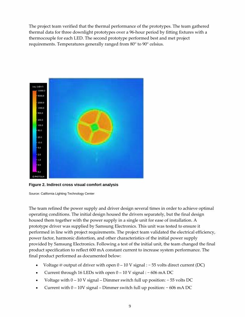
Figure 2 shows the visual comfort analysis results for the indirect cross concept. The indirect cross was shown to have an optical efficiency of 64% and a maximum brightness of 10,790 cd/m2. These results indicate that the indirect cross provides superior optical efficiency and visual comfort.
The indirect optical design approach reduced the visual discomfort and glare commonly associated with LED sources used in direct lighting designs. Additional considerations included analysis of LED emitters and thermal design to ensure LEDs operated within manufacturer recommendations.
Based on the emitter analysis results, the team determined that a higher color rendering index (CRI) value would be needed to meet ENERGY STAR criteria. Based on a survey of available LED providers, the project team determined that a Cree product would be the best choice for the LED. The team focused on the XR‐E emitter family and compared the P2 and P3 output groups. With the goal of meeting ENERGY STAR criteria for the downlight, the team compared the downlight’s output in lumens per watt (lm/w) and plotted the results against the associated drive current required. From the P2 and P3 analysis, the project team concluded that the higher‐output (P3) LEDs are preferable. Although these LEDs were more expensive, economies of scale in producing the downlights could reduce costs to some extent.
9
The project team verified that the thermal performance of the prototypes. The team gathered thermal data for three downlight prototypes over a 96‐hour period by fitting fixtures with a thermocouple for each LED. The second prototype performed best and met project requirements. Temperatures generally ranged from 80° to 90° celsius.
Figure 2. Indirect cross visual comfort analysis
Source: California Lighting Technology Center
The team refined the power supply and driver design several times in order to achieve optimal operating conditions. The initial design housed the drivers separately, but the final design housed them together with the power supply in a single unit for ease of installation. A prototype driver was supplied by Samsung Electronics. This unit was tested to ensure it performed in line with project requirements. The project team validated the electrical efficiency, power factor, harmonic distortion, and other characteristics of the initial power supply provided by Samsung Electronics. Following a test of the initial unit, the team changed the final product specification to reflect 600 mA constant current to increase system performance. The final product performed as documented below:
• Voltage @ output of driver with open 0 – 10 V signal : ~ 55 volts direct current (DC)
• Current through 16 LEDs with open 0 – 10 V signal : ~ 606 mA DC
• Voltage with 0 – 10 V signal – Dimmer switch full up position: ~ 55 volts DC
• Current with 0 – 10V signal – Dimmer switch full up position: ~ 606 mA DC

10
• Comparable results seen on 4 different driver units
Samsung Electronics also provided four additional drivers for use in the project. The CLTC team tested these units to verify the drivers’ performance relative to the final performance specifications and to ensure repeatability of results. Each module served two downlights. The driver utilized with pre‐production prototypes was a single‐channel unit with 24V DC input and 60V/0.6A output.
2.4. Prototype Fabrication and Testing The manufacturing partner for this project, Philips Capri Lighting, wanted a lighting system that would fit into standard existing downlight housings to ensure ease of retrofit installations, so the design was constrained to fit a 6.5”‐diameter housing. As a result, the cross heat sink size was reduced from original designs to leave room for the optic in the existing housing. In the first pre‐production prototypes provided by Philips Capri Lighting, the thermal design did not meet either the manufacturer’s requirements for thermal performance or ENERGY STAR performance criteria. In order to meet these requirements, different LEDs were selected for the final design, which also had lower source efficacy. In addition, the team fine‐tuned the heat sink design to meet the thermal specifications. The following figures show the initial and final indirect downlights. These units utilized the power supply and driver described in Section 2.2.
Figure 3. First prototype produced by Philips Capri Lighting, based on CLTC design (left) and final indirect downlight (right)
Source: California Lighting Technology Center
Table 3. Final indirect cross downlight performance test results
Source Lumen Output 825.0 lumens
Luminaire Lumen Output 486.8 lumens
Fixture Efficiency 59%
CRI 85.1

11
CCT 3,060 K
Power 16.2 W
Luminaire Efficacy 30.0 lm/W
Source: California Lighting Technology Center
Additional design work was conducted at the end of the project to update the indirect downlight concept light engine. The original design incorporated Cree XR‐E LEDs but during this project Cree released two new LEDs that are interchangeable electrically but offer increased performance over the XR‐E. These are the XP‐E and the XP‐G. The fixture below shows the redesigned circuit board for the XP LEDs.
Figure 4. Final circuit board design
Source: California Lighting Technology Center
The CLTC selected a high‐quality thermal interface material with low thermal impedance to optimize heat dissipation away from the high powered Cree XP LEDs. This material utilized a thick 2 oz. copper layer to optimize power transfer and heat mitigation throughout the cross‐design heat sink. The aluminum base layer, as opposed to typical double sided board stock that utilizes a fiberglass core, also contributed to optimal thermal performance of the revised design.

12
Figure 5. LED heat dissipation and chip schematic Source: The Berquist Compant
Following selection of the thermal insulation material, the CLTC determined the minimum trace width required for the circuits based on a maximum operating current of 700 mA and material properties of the insulation. The trace width required was found to be 2 mm. This value was verified by calculating the voltage drop across the circuit board, which is dependent on the trace width and was found to be negligible compared to the voltage draw of the eight LEDs contained in the design. While these changes did not increase the overall optical efficiency of the design, they did increase the light engine efficacy and total light output.
2.5. Prototype Demonstration The CLTC fabricated several prototypes using the final design and installed these units in local area displays. Four units are currently on display at the CLTC facility. These units are part of a kitchen vignette, which is used to demonstrate the lighting quality and energy savings of next‐generation downlights. Visitors to the facility can compare the indirect downlights to other LED and fluorescent products, also installed in the display. The units have drawn interest from manufacturers, lighting designers, and home owners regarding their availability.

13
Figure 6. Indirect downlight prototypes on display at CLTC
Source: California Lighting Technology Center

14

15
3.0 Project Outcomes The primary outcomes of this project are as follows:
• Developed performance specifications for an advanced LED downlighting system
• Identified challenges of using an indirect approach to mitigate the visual discomfort often associated with LED luminaires
• Developed several indirect optical designs, which showed promise to meet the performance goals
• Refined and selected promising designs for full prototype development
• Completed prototype testing and identified additional issues that should be addressed prior to commercialization
• Demonstrated pre‐production prototypes to show validity of the indirect concept for LED downlights
• Recommended increased optical and system performance for future indirect downlight system development

16
17
4.0 Conclusions and Recommendations
4.1. Conclusions The CLTC and Phillips Capri Lighting worked together to determine the feasibility of manufacturing the indirect downlight concept. After exhausting all viable options, it was determined that manufacturing and cost constraints would result in a downlight system that would not meet the performance specification. Because of this, Capri decided it would be best to commercialize a more traditional LED downlight system utilizing lessons learned during the design process of the indirect downlight project. The net result of this project was Philips Capri Lighting offering a reliable, efficacious LED downlight module (CRL6K‐14) that provides significant energy savings over equivalent incandescent technology. The specification sheet provided by Philips Capri Lighting may be found in attachment A.
4.2. Recommendations The California Lighting Technology Center continues product development and research on indirect downlight concepts and other light distribution designs. These designs have the ability to mitigate the visual discomfort commonly associated with LED luminaires. In particular, CLTC recommends that manufacturers pursue emerging next‐generation optical coating and films to improve optical efficiency, which allow indirect designs to achieve the system efficacies necessary to compete with traditional downlights.
4.3. Benefits to California Once commercialized, this product can save California money by lowering maintenance costs due to longer product life and result in energy savings up to 75 percent compared to incumbent compact fluorescent lamp downlights.

18

19
Glossary
Specific terms and acronyms used throughout this work statement are defined as follows:
Acronym Definition AEC Architectural Energy Corporation
C Celsius CCT Correlated color temperature
Commission California Energy Commission CLTC California Lighting Technology Center CFL Compact fluorescent lights CRI Color rendering index DC Direct current FC Footcandles GW Gigawatt HID High intensity discharge K Kelvin temperature
kcd/m2 Kilocandelas per square meter LED Light-emitting diode LM Lumens
lm/W Lumens a Watt LPD Lighting Power Density kW Kilowatt kWh Kilowatt-hour mA Milliamps MW Megawatt
MWh Megawatt Hour PIER Public Interest Energy Research SMPS Switch Mode Power Supply Vdc Volts direct current V Volts W Watts
W/sqft Watts per square foot

20

21
Attachment A