Embed Size (px)
Citation preview

The Rammer and Nibbler Page i
Report on the Gulper, Rammer and
Nibbler Development
The Kampala Sanihub Project
March 2014
Submitted by:
Water For People, Uganda
Plot 9, Olumi Close, Kitante, Kampala

The Rammer and Nibbler Page ii
EXECUTIVE SUMMARY
Water for people’s Sanitation as a business program’s research and development arm, the
Kampala Sani-Hub Project began collaboration with the Water Research Council (WRC) in
South Africa, under the Sanitation Research Fund for Africa (SRFA), to better understand the
process of developing new sanitation technologies which meet the needs of the market. The
project is based in Kampala, Uganda, where, amongst other technologies, the primary focus
is on the development of low cost semi-mechanical pit emptying devices such as the Rammer
and Nibbler and a decentralized faecal sludge treatment plant.
The research on the Rammer and Nibbler was conducted at the Kampala Sanihub led by two
Researchers, Sam Malinga and Herbert Atayo who are both Engineers. This research was
undertaken to develop better devices that could pump thick sludge, cleaner, go deeper and are
affordable to entrepreneurs wishing to start a pit emptying business. Slump cone tests were
carried out to determine the consistency of wetness and fluidity of a synthetic sludge which
would be used to estimated shear strength of synthetic sludge. Shear strength of 100pa,
500pa, and 2kpa were selected to determine the pumping limit of existing pumps. Synthetic
sludge comprising of 85% top soil and 15% kaolin clay were prepared for pump testing for
respective shear strength calculated.
Pump testing was performed on the Gulper, Rammer, and Nibbler. The parameters evaluated
include; time taken to prime, insertion and removal from the pit, and output within 30
seconds. The results showed that the Rammer was capable of pumping sludge of up to 500pa
shear strength with a greater discharge than other devices.
The design improvements were carried out on both the Rammer and Nibbler. For the
Rammer, the donkey tail was incorporated, both the fixed strut and internal rising bar were
made modular to allow the device to enter deeper into a pit, and inner fixed cylinder bend
was reduced to 25° to limit flow restrictions. The Nibbler design improvements were made
on the chain, delivery, discs, and smooth chain movement.
The technologies were demonstrated to the operators and desktop survey was carried out to
gain feedback on these devices. This report also contains further recommendations to be
made to the devices.

The Rammer and Nibbler Page iii
TABLE OF CONTENTS
EXECUTIVE SUMMARY ....................................................................................................... ii
LIST OF TABLES .................................................................................................................... vi
LIST OF FIGURES .................................................................................................................. vi
LIST OF ABBREVIATIONS .................................................................................................. vii
1.0 Introduction and Background ............................................................................... 1
1.1 Main Objectives of the Research ................................................................................ 2
2.0 Existing Emptying Methods ................................................................................. 3
2.1 Rudimentary Emptying ................................................................................................ 3
2.2 Cesspool Emptier ......................................................................................................... 3
2.3 Gulping ........................................................................................................................ 3
3.0 Testing Existing Devices on Synthetic Sludge ..................................................... 4
3.1 The Gulper ................................................................................................................... 4
3.2 The rammer ................................................................................................................. 4
3.2.1 Handle .................................................................................................................. 5
3.2.2 The internal rising bar .......................................................................................... 5
3.2.3 The Fixed Strut ..................................................................................................... 5
3.2.4 External rising bars ............................................................................................... 5
3.2.5 Fixed Cylinder ....................................................................................................... 5
3.2.6 The hose Pipe ....................................................................................................... 5
3.2.7 Outer Rising Cylinder ........................................................................................... 5
3.3 The Nibbler .................................................................................................................. 6
3.4 Slump Cone Tests ........................................................................................................ 6
3.4.1 Procedure of slump cone tests ............................................................................ 6
3.4.2 Results of slump cone test ................................................................................... 7
3.5 Preparation of Synthetic Sludge ................................................................................ 10
3.6 Pump Testing ............................................................................................................. 10
3.6.1 Procedure ........................................................................................................... 10
3.6.2 Results and Discussions of the Pumping Test .................................................... 11
3.6.3 Test Analysis of the Gulper ................................................................................ 13
3.6.4 Test Analysis of the Rammer ............................................................................. 13
3.7 Test Analysis of the Nibbler ...................................................................................... 14
4.0 Development of the Improved Rammer and Nibbler ......................................... 15
4.1 Development of the Rammer ................................................................................... 15
4.1.1 Introduction ....................................................................................................... 15
4.1.2 The Mechanism and principle of operation ...................................................... 15

The Rammer and Nibbler Page iv
4.1.3 Prototype development ..................................................................................... 15
4.2 Design improvements ............................................................................................... 16
4.3 Design ........................................................................................................................ 16
4.3.1 Pipe sizing ........................................................................................................... 16
b) The height of the Rammer ..................................................................................... 17
4.3.2 Total Volume to be occupied by sludge ............................................................. 17
4.3.3 Mass, m .............................................................................................................. 18
4.3.4 Weight, W .......................................................................................................... 18
4.3.5 Fabrication materials ......................................................................................... 19
4.4 Development of the Nibbler ..................................................................................... 21
4.5 The development of the second generation Nibbler ................................................ 21
4.6 The operating principle ............................................................................................. 21
4.7 Design analysis of the Nibbler ................................................................................... 22
4.8 Design improvements ............................................................................................... 24
4.9 Test performance on synthetic sludge ...................................................................... 24
5.0 Operators feedback ............................................................................................. 25
5.1 Feedback on the Rammer ......................................................................................... 25
5.1.1 Challenges of the Rammer ................................................................................. 25
5.2 Feedback on The Nibbler .......................................................................................... 25
5.2.1 Challenges of the Nibbler................................................................................... 25
5.2.2 Way forward for the Rammer ............................................................................ 26
5.2.3 Way forward for the Nibbler ............................................................................. 26
6.0 Further development ........................................................................................... 27
6.1 Peddler ...................................................................................................................... 27
6.2 New Valves ................................................................................................................ 27
7.0 Conclusions and Recommendations ................................................................... 28
7.1 Conclusions................................................................................................................ 28
7.2 Recommendations .................................................................................................... 28
References 29
Appendices 30
Appendix A: Pictures of pump testing of the Gulper ........................................................... 30
Appendix B: Pictures of pump testing for the Rammer ....................................................... 31
Appendix C: Launching of new devices and getting operators feedback ............................ 32
Appendix D: Field testing the Rammer during the sanitation week ................................... 33
APPENDIX E: OPERATOR FEEDBACK QUESTIONNAIRE ........................................................ 34

The Rammer and Nibbler Page v

The Rammer and Nibbler Page vi
LIST OF TABLES
Table 1: Design Chart for Slump cone ...................................................................................... 9
Table 2: Results based on 100pa .............................................................................................. 12
Table 3: Results based on 500pa .............................................................................................. 12
Table 4: Bill of materials ......................................................................................................... 19
LIST OF FIGURES
Figure 1: The Rammer prototype 2 ............................................................................................ 4
Figure 2: Mixing top soil and kaolin clay .................................................................................. 6
Figure 3: (a) Gently removing slump cone and (b) Slump allowed to settled for 30s ............... 7
Figure 4: (a) Measuring the slump and (b) Collapsed Matrix ................................................... 7
Figure 5: shear strength from slump reading versus water content ........................................... 9
Figure 6: Hooking the barrel to lower it into the pit ................................................................ 11
Figure 7: Weight of sludge to be lifted shaded black .............................................................. 13
Figure 8: Portion of sludge to be lifted .................................................................................... 14
Figure 9: Force acting on the handle........................................................................................ 19
Figure 10: Force diagram ......................................................................................................... 22
Figure 11: disc.......................................................................................................................... 22
Figure 12: Nibbler testing ........................................................................................................ 24
Figure 13: The Peddler Rammer .............................................................................................. 27
Figure 14: New valves design .................................................................................................. 28

The Rammer and Nibbler Page vii
LIST OF ABBREVIATIONS
FSM Faecal Sludge Management
SAAB Sanitation As A Business
SRFA Sanitation Research Fund for Africa
WFP Water For People
WRC Water Research Commission
KCCA Kampala City Council Authority

The Rammer and Nibbler Page 1
1.0 Introduction and Background
Water for People (WFP) is a United States registered non-governmental organisation with
solid presence in Latin America, Asia and Africa (Uganda, Rwanda and Malawi).
WFP brings together local entrepreneurs, civil society, governments, and communities to
establish creative, collaborative solutions that allow people to build and maintain their own
reliable safe water systems. Empowering everyone transforms people’s lives by improving
health and economic productivity to end the cycle of poverty. WFP’s vision is a world where
all people have access to safe drinking water and sanitation, a world where no one suffers or
dies from a water or sanitation-related disease.
WFP is currently implementing the Sanitation As A Business (SAAB) program, a market
based approach to improving access to sanitation, which aims to develop and support
sanitation businesses such as latrine construction and a pit emptying service using a semi
mechanical hand pump known as the Gulper.
The SAAB program’s research and development arm, The Sani-Hub Project began
collaboration with the Water Research Council (WRC) in South Africa, under the Sanitation
Research Fund for Africa (SRFA), to better understand the process of developing new
sanitation technologies which meet the needs of the market. The project is based in Kampala,
Uganda, where, amongst other technologies, the primary focus is on the development of low
cost semi-mechanical pit emptying devices such as the Gulper and a decentralized faecal
sludge treatment plant. Using these innovations, the SAAB program aims to develop business
which adds value at each stage of the sanitation value chain, from capture and storage, to pit
emptying, sludge transport and treatment, through to reuse.
Faecal Sludge Management is one of the greatest challenges facing urban authorities today
with the rate of pit fill up exceeding their capacity both technically and financially to empty
and dispose. FSM is becoming an important issue in Uganda’s urban centers especially in
slums where vacuum tankers cannot access the majority of pits. Batch of latrines can be seen
abandoned in various homes and many other open spaces, and this constitutes a crucial
problem to human beings in particular and the environment in general.
Many evidences show that a key driver towards increased efficiency in FSM is the
involvement of all stakeholders including, the waste generators, waste processors, formal and
informal sectors, financial institutions and private initiatives such as non-governmental and

The Rammer and Nibbler Page 2
community based organizations (Kassim and Ali, 2006). These technologies will however
improve pit emptying services to people living in unplanned settlements.
1.1 Main Objectives of the Research
To access the performance limit of existing pit emptying devices
To develop a pump that reaches further in to the pit and is cleaner, quicker and easier
to operate than the Gulper.
To develop a device that can pump thicker sludge.
To get operator and business feedback on the new technologies.

The Rammer and Nibbler Page 3
2.0 Existing Emptying Methods
This covers the common methods of pit emptying which include; cesspool empting, Gulping
and rudimentary methods.
2.1 Rudimentary Emptying
The habit of releasing untreated faecal matter into the environment is still persistent; most
households living in unplanned settlements like Naguru Go-down, Kamwokya, Kisenyi,
Kibuli, Bwaise, and Natete have a tendency to construct their pits near drainage channels.
During periods of heavy downpour they crack some holes into the pit and release the faecal
sludge into the flood water and this has caused a lot of health problems in the neighborhoods
and this practice has always been attributed to a lack of affordable pit emptying services.
2.2 Cesspool Emptier
There are about 29 vacuum tank trucks serving Kampala and the neighboring districts of
Wakiso and Mukono. These tanks mostly pump liquid slurry and can only service those
facilities which have a clear path for the truck to pass. This has left many facilities unattended
and thus the birth of the gulping pit emptying business.
2.3 Gulping
As part of WFP commitment towards improved sanitation, SAAB launched gulping business
in December 2012 to improve sanitation in unplanned settlements which cannot access
improved sanitation services either because they unable to access modern cesspool emptier or
the quality of the faecal sludge in their pits cannot be pumped by the cesspool emptier. When
gulping was introduced in Uganda, it received a warm welcome in these unplanned
settlements. It was looked at as a heavenly solution to their problems. After a marketing
campaign, 10 entrepreneurs purchased this technology to create their own pit emptying
businesses. A gulping team consists of at least two people having gulping equipment which
include the Gulper, barrels, protective gear, jerricans, a hook and a pickup truck for
transporting the waste to Bugolobi wastewater treatment plant. Few months down the road
these entrepreneurs came to realize the operational limits of the Gulper; it could not pump
thick sludge which is commonly present at the bottom of pits and does not also go deeper into
the pit. KCCA has refused to legalize the use of the Gulper for pit emptying because of the
nature in which faecal sludge is handled during gulping operation, though they do not oppose
using it.

The Rammer and Nibbler Page 4
3.0 Testing Existing Devices on Synthetic Sludge
Synthetic sludge of known shear strength was made to test the existing pumps in a controlled
environment. These tests gave a better understand how the pumps function and fail without
having to work with faecal sludge.
Synthetic sludge was prepared by mixing top soil and kaolin clay. This test embraces slump
cone tests, synthetic sludge preparation, pit set up, and pump testing. The devices tested and
evaluated were the Gulper, Rammer, and Nibbler.
3.1 The Gulper
The Gulper is a simple direct lift pump which operates in a similar way a borehole works. It
is designed to partially empty existing pit latrines of the supernatant layer at the top of the pit.
The standard gulper will reach 1m -1.5m in to the pit.
3.2 The rammer
The Rammer uses direct lift mechanism to pump sludge using outer
rising cylinder and delivers it to the barrel through a hose pipe which
is meant to make the operation of pit emptying cleaner. It can be
extended 3 meters into the pit. The Rammer components include:
outer rising cylinder, fixed inner cylinder with valve, fixed strut,
internal rising bar, external rising bars, cage, butterfly valve, and
handle. Please refer to page 14 of the rammer technical drawings in
relation to the description of the device’s components below.
Figure 1: The Rammer prototype 2

The Rammer and Nibbler Page 5
3.2.1 Handle
This is connected on the top of the internal rising bars; the lifting force is applied at this point
to provide up and downward stroke for the outer rising cylinder.
3.2.2 The internal rising bar
The internal connecting bar has a drilled hole at the top where the handle is bolted. The slot
insert with drilled holes is welded at the bottom of internal rising bar.
3.2.3 The Fixed Strut
The fixed strut is connected to vertical extension on the fixed inner cylinder. The strut houses
the inner connecting bar and is where slot is cut for movement of external rising bars. The
plug that closely enters into the fixed strut is fitted to prevent contraction of the slot thus easy
drive of the external rising bars.
3.2.4 External rising bars
The two external rods are bolted externally to outer rising cylinder and slot insert which is
welded on the internal rising bar. It moves the outer rising cylinder up and down.
3.2.5 Fixed Cylinder
This is smoothly bent to an angle of 25° to permit smooth flow of sludge into the hose pipe. It
has fixed buttery valves that control the flow of sludge into the pipe. It also has vertical
connection where the fixed strut is linked.
3.2.6 The hose Pipe
The pipe enables sludge to be directly pumped into the barrel so as to prevent spillage during
transfer of sludge using jerricans.
3.2.7 Outer Rising Cylinder
This is the moving cylinder of the Rammer, which collects sludge and houses the cage and
first butterfly valve. External rising bars are bolted here. As apposed to the gulper which has
no external moving parts, the rising cylinder is pushed into pit sludge, thus allowing thicker
sludge to enter into the device.

The Rammer and Nibbler Page 6
3.3 The Nibbler
This is a pit emptying device which is meant to remove thicker sludge which cannot be
removed by the Gulper. It uses the same principle as the rope pumps. It has a motor bike
chain instead of a rope and also has circular discs attached to the chain for picking sludge.
3.4 Slump Cone Tests
This is an empirical method used to determine the consistency of wetness and fluidity of
sludge. This aided in approximation of shear strength of the synthetic sludge which was used
for testing existing pumps.
3.4.1 Procedure of slump cone tests
Top soil of 8500g by dry mass was mixed with kaolin clay of 1500g making top soil 85% by
dry mass and Kaolin clay 15%. The recipe was thoroughly mixed in a bucket as seen in
Figure 2.
Figure 2: Mixing top soil and kaolin clay
Initial 2200g of water was added to the mix to make a simulant mix. After making the
simulant mix, varied amounts of water were added to the matrix and for each addition a
slump cone test was performed. A slump cone test involved filling a standard slump cone of
base diameter of 200mm, top diameter of 100mm and height of 300mm with the synthetic
sludge. The synthetic sludge was well compacted to ensure that no voids were within the
cone. When the cone was fully filled with synthetic sludge, the slump cone was gently
removed. After removing the cone, the cone shaped matrix was allowed to settle for 30
seconds as shown in Figure 3 and subsequently the slump was measured.

The Rammer and Nibbler Page 7
Figure 3: (a) Gently removing slump cone and (b) Slump allowed to settled for 30s
The whole procedure of adding water and measuring the slump was carried out until the
matrix collapsed completely.
Figure 4: (a) Measuring the slump and (b) Collapsed Matrix
3.4.2 Results of slump cone test
There was a gradual increase in slump with each addition of water. However there was a lot
of deviation from the theoretical values (Radford 2013). For example, for 18% water content
which corresponded to a theoretical slump of 4.16mm, a slump of 18mm was measured
which was far away from our prediction as shown in the Table 1. This drastic deviation was
as a result of our simulant mix. The top soil used had 8% moisture content; less organic
content, finer particles with a density of 918.2kgm-3 yet the soil for which our modules were
based on had 18% moisture content, a higher organic content and a density of 367.28kgm-3.
Also the bench mark kaolin clay had a density of 999.82kgm-3 with granular particles
whereas the sample of kaolin clay used was powdery with a density of 550.92kgm-3.
Nevertheless different modules which correlated linearly with the simulant parameters were
developed by plotting shear strength from slump reading against water content as seen in
Figure 5.
The results from the slump cone tests were tabulated in an excel sheet which had these
equations (Jamie, 2013) fed in each column to generate values in Table 1.
Water content (total mass basis), equivalent to (1-TS) sw
w
mm
m
mass total
watermassWC
a b

The Rammer and Nibbler Page 8
Water content (dry mass basis) s
w
m
m
solids massdry
watermassmc
Conversion factors – water content on dry/total mass basis,mc1
mcWC
,
WC1
WCmc
Embodied water content (total mass basis) – determined by oven drying sample of topsoil
mass total
solids with bound water massWCE
Total water content (total mass basis) – includes embodied water content and water added to
simulant mix
mass total
simulanthin water witmass totalWCT
Normalised WC, based on tests on the 60% kaolin, 40% topsoil (by dry mass) simulant
shown in 'Chart' ETEN B.WC).WCA.WC(1WC
Normalisation parameter – gradient A = 2.25
Normalisation parameter – intercept B = 1.25
Equation to calculate total WC from normalised WC and embodied WC
)A.WC(1
)B.WC(WCWC
E
ENT
Correlation between shear strength and normalised water content
NWCβατ
Regression parameter – intercept α = 67556
Regression parameter – gradient β = 1.7707E-006
Equation to calculate required normalised WC for target shear strength
)log(
)log()log(
NWC
Correlation between slump and shear strength qpτS
Regression parameter – intercept p = 18316
Regression parameter – gradient q = -0.77

The Rammer and Nibbler Page 9
Table 1: Design Chart for Slump cone
Addition
Water
added
in g
Cumulative
water
added in kg
Water
content
in kg
Total
water
content
WCt
Normalised
water
content
Shear
strength
from
NWC
Theoretical
slump
Actual
slump
Shear
strength
from AS
1 200 0.2 2.40 0.18 0.02 49653.02 4.16 18 7511.371
2 100 0.3 2.50 0.19 0.03 44182.99 4.55 24 5184.605
3 100 0.4 2.60 0.19 0.04 39384.43 4.98 36 3074.638
4 200 0.6 2.80 0.21 0.06 31454.03 5.92 48 2122.22
5 200 0.8 3.00 0.22 0.07 25285.46 7.02 62 1526.003
6 200 1 3.20 0.23 0.09 20454.36 8.27 80 1098.76
7 200 1.2 3.40 0.24 0.11 16645.86 9.71 90 944.0276
8 200 1.4 3.60 0.25 0.12 13624.56 11.34 140 534.207
9 200 1.6 3.80 0.26 0.14 11213.26 13.19 166 428.9181
10 200 1.8 4.00 0.27 0.15 9277.63 15.28 196 346.2583
11 200 2 4.20 0.28 0.16 7715.17 17.63 214 309.1918
12 200 2.2 4.40 0.29 0.18 6447.19 20.27 231 280.1862
13 200 2.4 4.60 0.30 0.19 5412.88 23.21 254 247.9282
A graph of shear strength against water content
Figure 5: shear strength from slump reading versus water content
2000
500

The Rammer and Nibbler Page 10
A graph of shear strength against water content shows a linear relationship. Using the fact
that the more water added, the weaker the matrix became. Synthetic sludge of required shear
strength was prepared using the graph. Intersection of a horizontal line drawn from the
required shear strength to the gradient corresponds to the amount water to be added to the
recipe and read from horizontal axis on water content.
3.5 Preparation of Synthetic Sludge
The three barrels of synthetic sludge of shear strength 100pa, 500pa, and 2kpa were prepared
to test the existing pumps in a controlled environment. From the slump cone tests shear
strength of 100pa, 500pa and 2kpa could be achieved using our recipes. Exactly 85% of our
top soil by dry mass and 15% of our kaolin clay needed 0.32% of water to attain shear
strength of 100pa. For 500pa, 0.27% of water and 2kpa needed 0.23% of water as shown by
dotted lines in Figure 5. The synthetic sludge was made in small portions to make mixing
easier. The mass of 1500g of kaolin clay was measured and poured in a basin and 9239g of
top soil was measured taking in consideration the amount of water embedded in the top soil
and was added to the kaolin clay in the basin. Varying amounts of water were then added. For
100pa each time 4120g of water was added, 3174g for a 500pa and 2410g for 2kpa shear
strength. Three 220L barrels were filled with the varying simulant mixes. The resultant
mixtures in the respective barrels were again re-mixed to ensure uniformity of the matrix as
there was a tendency of soil to settle at the bottom.
3.6 Pump Testing
This was primarily done to establish the range of shear strength over which the available pit
emptying devices could operate.
3.6.1 Procedure
The tests started with the 100pa barrel which was lowered into the pit using chain block
hooked on to a metal frame shown in Figure 6.
The slab was placed on the pit and thereafter a super structure was laid on the slab to mimic a
typical pit emptying operation.

The Rammer and Nibbler Page 11
Figure 6: Hooking the barrel to lower it into the pit
The Gulper, Rammer, and Nibbler were tested one at a time. For each device, different
parameters were evaluated; the ability of operators of different weights to operate, time taken
to prime, rate of output, time taken to insert into the pit, time taken to remove the device from
the pit, ease of cleaning, robustness and ease of operation.
When the pumping test was completed for the 100pa barrel, the barrel was removed from the
pit and replaced with the 500pa barrel, after which the testing was repeated. The same
procedure was done for the barrel of shear strength 2kpa.
3.6.2 Results and Discussions of the Pumping Test
This contains all the measured time taken to insert, prime and remove the devices and the
resultant mass of synthetic sludge obtained after 30 seconds of pumping at different shear
strengths as shown in Table 2 and 3.

The Rammer and Nibbler Page 12
Table 2: Results based on 100pa
Name of
the pump
Operator Time
taken to
prime /s
Time to
insert
device into
the pit (s)
Mass(g) of
sludge pumped
in 30s
Time to
remove device
from the
pit(S)
Gulper Habert A (60 kg) 16 14 17462 26
Gulper Samuel M (80 kg) 15 14 17888 26
Gulper Habert A & Samuel
M
10 14 27585 26
Rammer Habert A (60 kg) 13 20 16485 (21485
when hose
emptied)
13
Rammer Samuel M (80 kg) 12 20 19460 (31960
when hose
emptied)
13
Rammer Habert A & Samuel
M
10 20 35000 13
Nibbler Samuel M (80 kg) Could not
prime
10 0 15
Table 3: Results based on 500pa
Name of the
pump
Operator Time taken
to prime /s
Time to
insert device
into the pit
(s)
Mass(g) of sludge
pumped in 30s
Time to remove
device from the
pit(s)
Gulper Habert A (60
kg)
Failed after
125s trial
14 Failed 30s
Gulper Samuel M (80
kg)
Failed after
180s trial
14 failed 34s
Gulper Habert A &
Samuel M
Failed after
240s trial
14 failed 33s
Rammer Habert A (60
kg)
Failed 20 failed 25s
Rammer Samuel M (80
kg)
214 20 19460
(pumped by
Habert & Sam)
15s
Rammer Habert A &
Samuel M
22 20 30500 15
Nibbler Samuel M (80
kg)
Could not
prime
12 0 18

The Rammer and Nibbler Page 13
3.6.3 Test Analysis of the Gulper
The priming of the Gulper was easy for 100 pa and pumping was tiresome as a person of 60
kg could operate it for a short time and became exhausted quickly. Insertion of the Gulper
into the pit was simple but its removal from the pit was cumbersome and it needed two
people due to accumulation of sludge along the column of the Gulper. Cleaning the Gulper
took four minutes. For 500 pa, the gulper failed to prime even when operated by two people.
This was due primarily to the increase in shear strength of sludge, which the
plunger struggled to overcome, and thus it was difficult for the simulant to
enter into the column. Furthermore, the increase in density of the simulant
increased the load, meaning a greater force was required to lift the simulant
out of the pit.
The portion shaded black in figure 7 indicates the vertical weight of sludge
to be lifted that made the Gulper fail to pump sludge of shear strength
500pa. The propensity of sludge to amass in the column of the Gulper made
pumping hard. Above all, the Gulper does both delivery and suction
(pulling sludge) concurrently thus a bigger force is normally required for its
operation.
Figure 7: Weight of sludge to be lifted shaded black
3.6.4 Test Analysis of the Rammer
Priming the Rammer using 100pa sludge took less time than the one taken by the Gulper
because it had a shorter column to be filled with sludge. Insertion of the Rammer into the pit
was much easier and one person could also remove it from the pit. This was also attributed by
shorter column of the Rammer. Cleaning the Rammer took more time and water than the
Gulper. With 500pa, the Rammer was able to pump. This was because the Rammer does not
pick sludge by suction, instead the downward stroke of the outer rising cylinder pushes into
the sludge, thus forcing it to pass through the butterfly valve and into the cylinder the upward
stroke then lifts the sludge into the inner fixed cylinder as seen in Figure 8. Back flow of
sludge is prevented by the second butterfly valve attached to the inner fixed cylinder.
Continuous up and down motion of the outer rising cylinder causes sludge to accumulate in
the inner fixed cylinder until it is discharged through the hose pipe.

The Rammer and Nibbler Page 14
.
Figure 8: Portion of sludge to be lifted
3.7 Test Analysis of the Nibbler
The first prototype which was developed by Steve Sugden was not properly fabricated; the
link chain could not rotate smoothly as the motion constantly got locked at short intervals. It
picked little sludge but could not deliver it and the sludge eventually rolled back.

The Rammer and Nibbler Page 15
4.0 Development of the Improved Rammer and Nibbler
This section covers the design and operational improvements carried our on these devices to
address the challenges witnessed during pump tests.
4.1 Development of the Rammer
4.1.1 Introduction
The Rammer was developed by Steve Sudgen using the principle of direct lift: The design
concept was to have the moving parts external for easy cleaning. The improved Rammer
components include: outer rising cylinder, fixed inner cylinder with valve, modular fixed
strut and internal rising bar, external rising bars, cage, butterfly valve, rubber seal, and
adjustable donkey tail. The hose pipe is usually clamped on the outlet of the fixed inner
cylinder and then directed to the barrel for delivering sludge. Thus the operation is improved
as there is no need for fetching the sludge in jerry cans, which often causes spillage. The
suction pipe is submersible depending on the depth of the pit.
4.1.2 The Mechanism and principle of operation
The up and down stroke of the internal rising bar provides power to the external bars for
lifting and lowering the outer rising cylinder. Unlike the Gulper, the development of the outer
rising cylinder means that during the down stroke the outer rising cylinder is pushed into the
sludge and it is forced into the cylinder. This is what enables the rammer to pump thicker
sludge than the gulper. The upward stroke allows the sludge collected in the rising cylinder to
be conveyed into the fixed inner cylinder through upper butterfly valve.
The sludge collected into the fixed inner cylinder keeps on amassing during the upward
stroke and back flow is prevented by the fixed upper valve, thus priming the device. The
upward stroke lifts the collected sludge easily until it reaches point where it starts to transfer
it to the hose pipe where an additional force is required to overcome the column weight of the
sludge that has accumulated. Sludge is then discharged from the suction hose directly into a
barrel.
4.1.3 Prototype development
The Rammer was designed and developed to meet the criteria that it must be:
Able to go further into the pit for at least 3 m
Cleaner during operation and easy to clean
Affordable to entrepreneurs

The Rammer and Nibbler Page 16
Capable of pumping thick sludge
Fast and calm to operate
Locally fabricated, materials readily available and easy to repair
Easy to assemble, disassemble and transport
4.2 Design improvements
Adjustable donkey tail which is detachable was designed and incorporated with the
footstool so as to minimize the load applied to the fixed strut that may cause it to
bend.
The internal rising bar was made modular such that it can be extended using a pipe of
diameter 20 mm that is bolted into it. This enables the rammer to reach deeper into a
pit.
Similarly, by using threaded pipes joined using a socket, the fixed strut can also be
extended in 1m sections, thus allowing the device to reach deeper into a pit.
4.3 Design
These are steps taken in developing the Rammer to standard dimensions and for optimum
operation.
4.3.1 Pipe sizing
The pipe sizes were selected considering the following pit latrine parameters for easy
insertion and removal of the Rammer;
The length and width of the slab hole in the pit
The height of the toilet structure
The hole Length, L = 200 mm and width, W = 120 mm. These dimensions are based on the
standard size of a clay brick, which is often used to make the slab hole during casting.
a) The Plastic outer Cylinder;
The PVC pipes of φ = 110 mm and 90 mm could be used for fabrication of this component
part but for this research, 110 mm PVC pipe with thickness of 3.2 mm was used. The choice
of the pipe diameter was to allow The Rammer to be inserted into the pit without needing to
break the slab hole.

The Rammer and Nibbler Page 17
b) The height of the Rammer
Cage, PVC rising cylinder and fixed inner cylinder will all have height of 200mm, 530mm,
490 mm but since the inner fixed cylinder enters into PVC rising cylinder, their component
height is 800mm. The fixed strut and internal rising bar protrusion will be of height 1700mm.
Since the Rammer was inserted while slanting the whole component. It will enter well for a
typical latrine door of height 1.8m.
The device has been designed such that should it can be extended deeper into the pit, 1m
modular pipe sections are attached in situ. This prevents the need for the operator to remove
the device before making it longer.
4.3.2 Total Volume to be occupied by sludge
The volume of each pipe section was calculated using equation:
Where v is the volume
d is the internal diameter of pipe
h is the cylinder height
Volume of sludge in the PVC rising cylinder
Volume of sludge in the fixed internal bar
32
f 0.00445m4
0.70.09πv
900mmd
700mmh
Volume of sludge in the suction hose pipe
4
hπdv
2
rv
fv
sv
32
r 0.00447m4
0.530.1036πv
530mmh
103.6mmd

The Rammer and Nibbler Page 18
32
s 0.02722m4
60.0762πv
76.2mmd
6000mmh
The total volume to be pump
4.3.3 Mass, m
The mass of sludge being pumped was calculated using equation
Where is density of sludge and assumed to be 1500 kgm-3 (David and Mark, 2012)
Therefore,
Considering the mass of the PVC rising cylinder, cage with valve, external rising bars, and
internal rising bar to be 2 kg since these parts are also lifted.
The total was will be 17.21 kg during each upward stroke
4.3.4 Weight, W
Where g is the acceleration due to gravity, g=9.81ms-2
Therefore the weight to be lifted can be calculated
There is resistance to smooth movement of the pipe and assuming the coefficient of friction
to be for a pipe of ɸ=110 mm
Hence the friction force to be subdued will be
Consequently, the total force will be
Thus, the force applied to effectively pump the sludge should be greater than 171.7N
303614.002722.000445.000447.0 m
vvvv sfrT
Tvm
15.21kg15000.03614m
mgW
168.83N9.8117.21W
017.0
2.87N168.830.017μWf
171.7N2.87168.83FT

The Rammer and Nibbler Page 19
This weight is directly transferred to the lifting point on the inner rising bar;
Figure 9: Force acting on the handle
Therefore, L=171.7N and by taking moments about the pivot and considering the length of
the handle to be 1m. Thus, the minimum effort for equilibrium can be calculated
A healthy well-fed labourer over the course of an 8-hour day can sustain an average output
of about 75 watts (Tom, 2007).
The power required, 2.15watts8
0.357.23P
Therefore, most adults should be able to operate the Rammer effectively because the power
requirement is far below the maximum of 75 watts.
4.3.5 Fabrication materials
This contains the list of materials required for fabrication of the Rammer and detailed cost
break down. The materials are readily available in the following markets; Nakasero, Kisenyi,
Kiseka and Bwaise. Pentagon Technical Services is a local agro-process company that is
working with Sanihub Engineers to fabricate and refine the Rammer. Throughout the
technology development, the cost of the device has remained low to limit business start up
costs.
Table 4: Bill of materials
Item Quantity Unit Unit cost (£) Total cost ($)
PVC Rising cylinder
PVC pipe 110 mm, thickness 3.2 mm class
4 0.53 m 28 15
Fixed inner cylinder
Mild steel pipe 90 mm, thickness 1.5 mm 0.70 m 30 21
Butterfly valve 1 each 6 6
57.23NE
0.75E0.25171.7
0.25m
1m
Load (L)
Effort (E)

The Rammer and Nibbler Page 20
Mild steel 50 mm, thickness 3 mm 0.30 m 16 4.8
Round bars φ = 7mm 4 m 2.5 10
Rubber seal 1 each 4 4
Fixed support strut
Galvanised Iron 42 mm, 3 M 10 30
Slot plug 0.05 m 10 1
Footstool and donkey tail frame
Triangular foot stool 1 each 6 6
Vertical support 1 each 4 4
Donkey tail handle 1 each 6 6
Others
Internal rising bar 3 m 4 12
External rising bar 3 m 4 12
Cage with rising valve 1 each 10 10
Nuts and bolts 15 each 0.3 4.5
Washers 2 each 0.5 1
Hook 1 each 6 6
Subtotal 153
Hose pipe 6 m 10 60
Clamp 1 each 8 8
Labour (30%) 46
Total 267

The Rammer and Nibbler Page 21
4.4 Development of the Nibbler
Thick sludge at the bottom of non-flush pits has for long proved a bottle neck to full pit
emptying service providers. Many attempts have been made to develop thick sludge devices;
however none have successfully been taken to the market. The development of the pit screw
auger never went further than the development stage as it failed with the addition of solid
waste in pits, and required a very high RPM on watery sludge. The belt drive concept did not
also go beyond the concept itself. The Nibbler showed a great potential and was further
refined in South Africa into a gobbler which had two chains and its application was limited
due to its high weight and so many moving parts, the ideas of the Nibbler was abandoned
because of the difficulty in removing the sludge from the discs (David and Mark, 2012).
4.5 The development of the second generation Nibbler
Showing a lot of potential in something that can be refined further into a device of practical
application, more research is being conducted into the Nibbler. The second generation
Nibbler is more like the first generation. It consists of a motor bike chain onto which discs are
welded. The disc-chain assembly is constrained to move through two vertical PVC pipes by a
cylindrical joint at the bottom and a sprocket at the top. The sprocket is welded onto a handle
for turning. Rotating the handle at the top of the device causes the sprocket to rotate, forcing
the disc chain assembly to rotate in the same direction. During this motion, the disc scoops
thick sludge from the bottom of the pit latrine and force it into the rising pipe. When the
sludge reaches the top, it is scraped from the discs by a metallic scrapper into the delivery
hose. Sludge then gradually falls into a bucket underneath.
4.6 The operating principle
The Nibbler uses a the scoping principle as it’s primary means of operation, similar to eating
porridge. Dip your spoon in the porridge, scoop, take to your mouth and remove then back to
the porridge. The Nibbler has multiple circular discs which function using the same principle.
The discs welded onto motor bike chain act like spoons to scoop thick sludge. The discs are
welded offset onto the motorbike chain such that the surface area for scooping sludge is
maximum and also to allow more sludge to be removed from the discs by the scrapper.

The Rammer and Nibbler Page 22
4.7 Design analysis of the Nibbler
Figure 10: Force diagram
Figure 11: disc
column PipeRiser Effective disc of Area surface =v
column piperiser in the Volume=v
sludge ofDensity =
where;
vgmg=W
)(Wcolumn riser in the sludge ofWeight
19.62N9.8122g =W
4kg = discs pluschain of mass Total =W
2
assemblychain disc of weight Total =W
disc from sludge removinghen scrapper wagainst rubbing discs ofresult a as Resistance=W
overcome be tosludge of forceShear =W
columnriser in the sludge ofWeight =W
discs pluschain theofWeight = W
turn tohandhuman by appliedEffort = E
2
2
1
1
1
4
3
2
1
N0.05559.810.00565mass
0.00565m20.002827v
0.002827m
4
0.06π
4
πd= Area
3
2
2

The Rammer and Nibbler Page 23
Neglecting volume occupied by discs since they are only 2mm thick this is negligible
compare to the riser column of 2000mm and the density of thick sludge to be 2000kgm-3
(David and Mark, 2012)
= 0.0555×2000
=111N
Shear force of sludge to be overcome (W3)
The minimum effort required to be applied by the operator to just turn the handle is 92.793N
A healthy well-fed labourer over the course of an 8-hour day can sustain an average output
of about 75 watts (Tom, 2007).
Power required for operation over a period of 8 hours, 7.29watts8
0.2π92.793P
Therefore power required to operate the Nibbler is 7.92W which is much lower than 75W,
hence most people should be able to operate the Nibbler.
22
3
0.377m377000mm2000 188.5 =
piperiser theoflength disc of ncecircumfere = acts stressshear on which Area
188.5mm60ππddisc of nceCircumfere
columnriser ofLength disc of nceCircumfere =Area
Area stressShear W
92.793N=E
200E=9573.6+5655+3330
200)(E + 30)(19.62 = 30)(319.12 + 30)(188.5 + 30)(111 + 30)(19.62
200)(E + 30)(W = 30)(W + 30)(W + 30)(W + 30)(W
Opoint at moments Taking
319.12N=W
188.5+111+19.62=W
W+W+W=W
(W4) disc from sludge removinghen scrapper wagainst rubbing discs ofresult a as Resistance
188.5N=W
0.377500 =W
500pastrength shear of sludge gConsiderin
area stressshear =W
14321
4
4
3214
3
3
3

The Rammer and Nibbler Page 24
4.8 Design improvements
The discs were attached to the chain at the periphery exposing a large surface area for
scooping.
Welding discs on the chain at the periphery instead of the centre also exposed larger
surface of the disc from which sludge could be extracted at the top.
The top of the device was encased to reduce chances of contact with sludge.
It has a scrapper to aid removal of sludge from discs.
4.9 Test performance on synthetic sludge
When the new prototype was tested on 500 pa synthetic sludge, it was able to remove a
justifiable amount of sludge from the bottom and deliver it at top through the delivery
channel without struggle.
Figure 12: Nibbler testing

The Rammer and Nibbler Page 25
5.0 Operators feedback
This was carried out to obtain the opinions of existing pit emptying entrepreneurs for which
these devices are developed. This would enable the designers to improve the devices further.
Testing of the two equipment was done during the sanitation week by the 5 entrepreneurs
5.1 Feedback on the Rammer
The operators were impressed with the Rammer’s ability to pump thick sludge. They also
liked the donkey tail design used to aid pumping. They were all willing to return their
Gulpers and top up in exchange for the Rammer. Above all, the Rammer appears to have
been accepted by all operators.
5.1.1 Challenges of the Rammer
Cleaning the hose pipe was hard because the inner part cannot be accessed.
Insertion of the Rammer into some pit latrines was tough. The standard pit slab hole has
dimensions of 200 by 120 mm yet some pits have dimensions lower than that.
There is still escape of watery sludge through the clearance between the two cylinders. A
rubber seal has been installed to prevent this, however a better solution needs to be found
as it does not completely prevent water from escaping between the cylinders.
5.2 Feedback on The Nibbler
It was a very embarrassing moment to get feedback from entrepreneurs in the pit emptying
businesses. The entrepreneurs were excited at the sight of the Rammer, when it performed,
they nodded their heads on approval and they could be heard making praise comments on the
rammer. But when it came to testing the Nibbler, they did not want to know what the Nibbler
was and what it does. It was hard to convince them to test the Nibbler; only one entrepreneur
came closer to the Nibbler as most of them were all pointing at the Rammer.
5.2.1 Challenges of the Nibbler
The disc often got stuck at the point of forcing sludge into the riser pipe and at the
point of entry to the return pipe.
The scrapper caused a lot of resistance and thus made it hard to turn at intervals.
It was very difficult to clean the Nibbler as thick sludge tended to adhere onto the
chain and pipes.

The Rammer and Nibbler Page 26
The Nibbler was also very heavy to remove from the pit because both columns were
filled with sludge.
It was very difficult to remove the Nibbler from the pit as it got stuck in thick sludge,
which is also very sticky.
Most thick sludge is located at the base of pit latrines. Because the mechanism does
not allow it to be extended, the length of the nibbler is limited to fitting inside a latrine
superstructure – approximately 1.8m. Thus, the sludge that it is intended to remove
from the base of deep pits is not accessed.
Maintenance of the motorcycle chain could be challenging due to its continual contact
with water.
Negative operator feedback suggests that entry into the market will be challenging and
more technology development is required to prove the value of the device to pit
emptying operations.
5.2.2 Way forward for the Rammer
The outer rising cylinder and fixed inner cylinder of diameters 90 mm and 76 mm
respectively should be used instead of 110 mm and 90 mm so as to enable the
Rammer to be inserted easily into the pits without enlarging the prevailing slab hole.
There is a need to use a foam or rubber material to seal the space between the fixed
inner cylinder and outer rising cylinder, thus preventing watery sludge from escaping
through this clearance.
5.2.3 Way forward for the Nibbler
For smooth operation, the discs need to be welded at 90 degrees to the chain and
should properly align.
A spring loaded scrapper should be used to reduce the resistance when removing
sludge from the disc.
Guides should be introduced onto the lower cylindrical joint to prevent the chain from
deviating off alignment.
Funnel shaped enlargements should be provided onto the pipes at the point of
scooping sludge and at the point of entry onto the return pipe.

The Rammer and Nibbler Page 27
6.0 Further development
These are ideas that are to be tested as further developments are made to the devices. There
are high hopes that they can yield positives results, which can be further applied to improve
the performance of the Rammer. These include the peddler driving mechanism and a valve
that when open leaves a clear path for the sludge to pass through.
6.1 Peddler
The Rammer with peddle driving mechanism is away forward designed to easy and fasten the
pumping action because the leg muscles provide greater force and motion generated by
peddling is really swift to allow unimpeded flow of sludge from the pit into the barrel. This
idea is worth trying. However, the actual design of the Rammer will remain unchanged.
Issues to be considered:
To make fixed strut adjustable to permit pumping at different levels.
To put provision of a holder to enable peddler stay firm while
peddling.
Seat to be adjustable to cater for people of different heights.
Figure 13: The Peddler Rammer
6.2 New Valves
Current valves have a bar along the diameter of the pipe, which can trap detritus materials
such as hair and plastic bags. The new valve design should prevent this, and this will be
tested in the near future.
These valves are predicted to allow clear and uninterrupted flow of sludge into the cylinder.
Blockage will be minimal because the valves open at the center and are hinged at the sides.

The Rammer and Nibbler Page 28
Figure 14: New valves design
7.0 Conclusions and Recommendations
7.1 Conclusions
From the analysis of pump test results, operator feedback and the field tests, the Rammer is
an improved pump compared to the Gulper. Within WFP, a system is being developed in
which existing entrepreneurs can swap their gulpers for rammers. All new entrepreneurs will
be guided to Pentagon Technical Services to purchase a rammer.
From tests with synthetic sludge, the Nibbler can remove thicker sludge as long as it can flow
but due to its messy operation, entrepreneurs rejected the device. Further development is
required to make the device cleaner and therefore more appealing to pit emptying businesses.
7.2 Recommendations
A marketing strategy should be developed to take the Rammer into the market and also
convince KCCA to legalize its use for pit emptying as it is now cleaner than the Gulper and
its operations are more like the Cesspool emptier.
With the negative perception of the Nibbler by entrepreneurs due to its messy nature, further
developments should be aimed at fluidizing the thicker sludge which could be done by
incorporating a fluidizer into the existing devices or developing a separate fluidizing device
which can re-mould thicker sludge such that it can be pumped by the Rammer.

The Rammer and Nibbler Page 29
References
David. S and Mark. O. 2012. Tackling the challenges of full pit latrines, volume 3, and page
28.
Jamie. R, 2013. Slump cone experiment on synthetic sludge (unpublished).
Tom Gibson, Turning sweat into watts, IEEE Spectrum Volume 48 Number 7 July 2011, pp.
50-55.

The Rammer and Nibbler Page 30
Appendices
Appendix A: Pictures of pump testing of the Gulper
A – Barrel of synthetic sludge in test pit, B – The Gulper has been inserted for pump testing,
C – Removing the Gulper from the pit, D – Cleaning the Gulper by pumping sludge out
A B
C D

The Rammer and Nibbler Page 31
Appendix B: Pictures of pump testing for the Rammer
A – Parts of the Rammer prototype 2, B – The Rammer has been inserted for pump testing, C
– Cleaning hose pipe, D – The assembled Rammer
D C
B A B
A
D C

The Rammer and Nibbler Page 32
Appendix C: Launching of new devices and getting operators feedback
A – Showing the Rammer to entrepreneurs, B – The Rammer pumps thick sludge, C –
Explaining the difference between the Gulper and Rammer, D – Nibbler inserted into a pit
A B
C D

The Rammer and Nibbler Page 33
Appendix D: Field testing the Rammer during the sanitation week
A – Inserting the Rammer into a pit, B – The pit slab hole small for the Rammer to enter, C –
The Rammer pumps shit, D – The
A
D C
C
The Rammer and Nibbler Page 34
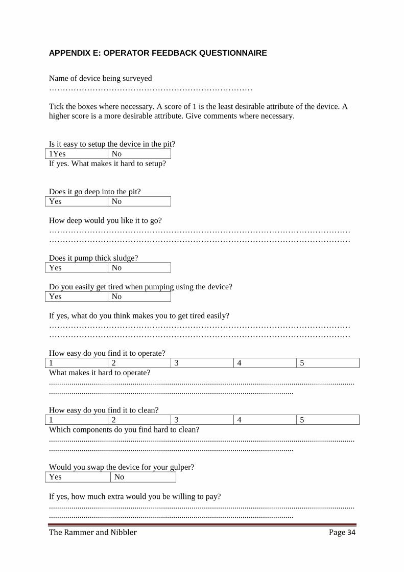
APPENDIX E: OPERATOR FEEDBACK QUESTIONNAIRE
Name of device being surveyed
…………………………………………………………………
Tick the boxes where necessary. A score of 1 is the least desirable attribute of the device. A
higher score is a more desirable attribute. Give comments where necessary.
Is it easy to setup the device in the pit?
1Yes No
If yes. What makes it hard to setup?
Does it go deep into the pit?
Yes No
How deep would you like it to go?
…………………………………………………………………………………………………
…………………………………………………………………………………………………
Does it pump thick sludge?
Yes No
Do you easily get tired when pumping using the device?
Yes No
If yes, what do you think makes you to get tired easily?
…………………………………………………………………………………………………
…………………………………………………………………………………………………
How easy do you find it to operate?
1 2 3 4 5
What makes it hard to operate?
......................................................................................................................................................
........................................................................................................................
How easy do you find it to clean?
1 2 3 4 5
Which components do you find hard to clean?
......................................................................................................................................................
........................................................................................................................
Would you swap the device for your gulper?
Yes No
If yes, how much extra would you be willing to pay?
......................................................................................................................................................
........................................................................................................................

The Rammer and Nibbler Page 35
Would you like to own one?
Yes No
How much would you be willing to pay for it?
......................................................................................................................................................
........................................................................................................................
What improvements would you like to be done on the device?
......................................................................................................................................................
........................................................................................................................
Thanks for your time
![MBARI Dorado AUV's Scientific Results · 2019. 1. 17. · 3). [Bird et al. 2007, Thompson 2007]. Fig. 2 CTD/Gulper AUV Science Payload (removed from nose of vehicle.) Fig. 1 CTD/Gulper](https://img.pdfslide.us/doc/110x75/5ff340271a5ff32ac35e51cd/mbari-dorado-auvs-scientific-results-2019-1-17-3-bird-et-al-2007-thompson.jpg)