Embed Size (px)
Citation preview
Report on Proposals – June 2010 NFPA 70_______________________________________________________________________________________________8-1 Log #4917g NEC-P08
_______________________________________________________________________________________________Caleb M. Ferris, Chadwick Electric
Add a diagram table after the scope of each article similar to the one in Article 430.For NEC user cost make the table layout diagram in 430.8 standard throughout the code.
Diagrams are not useful or practical for all articles. Submitter does not provide proposed diagrams,just a concept.
_______________________________________________________________________________________________8-2 Log #614f NEC-P08
_______________________________________________________________________________________________Paul Guidry, Fluor Enterprises, Inc.
Change terms "high voltage" and "medium voltage" to correlate with new proposed definitions inArticle 100.This is a companion proposal to a proposal to add definitions for low voltage, medium voltage, and high voltage to
Article 100.If the proposal for adding the definitions in Article 100 is accepted, this proposal must be accepted as
well to correlate between all chapters of the NEC.
Will not add clarity to the NEC. The code has established nominal voltages and terminology that iswell recognized in the industry.
_______________________________________________________________________________________________8-3 Log #3922 NEC-P08
_______________________________________________________________________________________________Goran Haag, Champion Fiberglass, Inc.
Add new text to read:Everywhere “Type RTRC marked with the suffix -XW” is mentioned, add “Type RTRC marked with the suffix –PW”.
Champion Fiberglass, Inc. is submitting to Underwriters Laboratories data for fact finding study for anew conduit made from a different wall thickness compared to the RTRC XW conduit. This conduit has the same orhigher impact and compression strength as Schedule 80 PVC and should therefore qualify for all instances whereSchedule 80 PVC is approved (as well as RTRC XW).
Proposers should identify by section with proposed text where revisions are to be made within thecode. Panel review of the fact finding report will be required prior to consideration of a proposal.
1Printed on 1/27/2009

Report on Proposals – June 2010 NFPA 70_______________________________________________________________________________________________8-4 Log #219 NEC-P08
_______________________________________________________________________________________________Terry Peters, The Society of the Plastics Industry
Revise as follows:A support designed expressly for holding wires, cables, and raceways with additional functions as
permitted in this . Cable trays include, but are not limited to the following types, ladder, ventilated, ventilatedchannel, ventilated trough, solid bottom, solid bottom with solid metal cover, solid channel, steel, aluminum, metallicand nonmetallic.
The term “cable tray” is used throughout the code without a definition. It should be defined. Thedefinition of “raceway” was used as a model in developing this definition.
The definition of a cable tray is included in Section 392.2, the Article that covers cable tray. Adding adefinition in Article 100 will not add clarity to the code.
_______________________________________________________________________________________________8-5 Log #217 NEC-P08
_______________________________________________________________________________________________Terry Peters, The Society of the Plastics Industry
Add new text to read:A unit or assembly of units or sections and associated fittings forming a structural system used to
securely fasten or support cables and raceways.The term “cable tray system” is used in multiple articles but the definition is in Article 392. The style
manual requires that a definition be placed in Article 100. The NEC style manual states:In general, Article 100 shall contain definitions of terms that appear in two or more other articles
of the .”
NEC Style Manual 2.2.2.1 allows the definition to be in Article 392. "Cable tray" is not a genericterm, it is a product and the definition more appropriately remains in Article 392 where the rules of installation appear.
_______________________________________________________________________________________________8-6 Log #4723a NEC-P08
_______________________________________________________________________________________________Jerry Lee Richardson, ESG
Add the following text to Article 100 as follows:Stranded conductor which has been compressed in manufacture to reduce voids.
In Table C.1(A), Table C.2(A), Table C.3(A), Table C.4(A), Table C.5(A), Table C.6(A), Table C.7(A), Table C.8(A),Table C.9(A), and Table C.10(A) delete the following text:Definition: Compact stranding is the result of manufacturing process where the stranded conductor is compressed to
the extent that the interstices (voids between strand wires) are virtually eliminated.A companion proposal has been sent to CMP-6 relative to the definition.
Definitions duplicated in ten tables will be replaced by a single definition in Article 100
This definition is applicable to the use and understanding of the tables in Annex C relative tocompact stranding. A reference back to Article 100 would need to be included at each table making the relocationproposed not user friendly.
2Printed on 1/27/2009

Report on Proposals – June 2010 NFPA 70_______________________________________________________________________________________________8-7 Log #220 NEC-P08
_______________________________________________________________________________________________Terry Peters, The Society of the Plastics Industry
Revise as follows:An enclosed channel of metal or nonmetallic materials designed expressly for holding wires, cables, or
busbars, with additional functions as permitted in this . Raceways include, but are not limited to, rigid metalconduit, rigid nonmetallic polyvinyl chloride conduit, intermediate metal conduit, liquidtight flexible metal conduit,liquidtight flexible nonmetallic conduit, high density polyethylene conduit, reinforced thermosetting resin conduit, flexiblemetallic tubing, flexible metal conduit, electrical nonmetallic tubing, electrical metallic tubing, underfloor raceways,cellular concrete floor raceways, cellular metal floor raceways, surface raceways, wireways, and busways, plenumsignaling raceway, riser signaling raceway, general-purpose signaling raceway, plenum optical fiber raceway, riseroptical fiber raceway, general-purpose optical fiber cable raceway, plenum communications raceway, risercommunications raceway, general-purpose communications raceway, plenum CATV raceway, riser CATV raceway andgeneral-purpose CATV raceway.
The proposed changes updates the list of raceways to include many that were not in existence whenthe definition of raceway was last revised. Most of these raceways are plastic raceways. The Society of the PlasticsIndustry would like to see the various types plastic raceways mentioned along with metallic raceways. In the firstsentence we propose deleting “of metal or nonmetallic materials” because it adds nothing to the definition. The secondsentence of the definition clearly informs the reader what materials are used to manufacture raceways.
Proposed changes do not improve clarity or content of existing text.
_______________________________________________________________________________________________8-8 Log #1995 NEC-P08
_______________________________________________________________________________________________Dan Leaf, Seneca, SC
Add: A pole enclosing conductors is not a raceway.Present definition includes poles which then applies all applicable provisions for raceways.
Some lighting poles can be a raceway. See 410.30(B).
3Printed on 1/27/2009
Report on Proposals – June 2010 NFPA 70_______________________________________________________________________________________________8-9 Log #2219 NEC-P08
_______________________________________________________________________________________________Jim Davis, Electrical Education Services, LLC
Add the auxiliary gutters wiring method to the list of recognized raceways in the second sentenceof this definition. “ An enclosed channel of metal or nonmetallic materials designed expressly for holdingwires, cables, or busbars, with additional functions as permitted in this code. Raceways include, but are not limited to,rigid metal conduit, rigid nonmetallic conduit, intermediate metal conduit, liquidtight flexible conduit, flexible metallictubing, flexible metal conduit, electrical nonmetallic tubing, electrical metallic tubing, underfloor raceway, cellularconcrete floor raceways, cellular metal floor raceways, surface raceways, auxiliary gutters, wireways, and busways.”
Clearly, an “auxiliary gutter” is a raceway as defined in the first sentence of “raceway” in Article 100.By including this wiring method in the long list of other wiring methods, four of which actually include the word“raceway” as the named wiring method, the question is raised as to why it is NOT considered a raceway. Auxiliarygutters find more frequent use in the electrical industry than some of the other wiring methods included in the list, and itsabsence from the list potentially creates confusion. Adding it to the list increases code consistency and usability.
While auxiliary gutters are used in some ways like raceways, their restriction of use prevents themfrom automatically being grouped with raceways. Auxiliary gutters shall be permitted to supplement wiring spaces atmeter centers, distribution centers, switchboards, and similar points of wiring systems.
_______________________________________________________________________________________________8-10 Log #2715 NEC-P08
_______________________________________________________________________________________________Dan Leaf, Seneca, SC
Add:"cablebus" and "auxiliary gutters" or alternatively "cablebus and auxiliary gutters are not raceways".
Since the definitions are not limited to the raceways listed, it leaves cable bus and auxiliary gutters inlimbo; they may or may not be considered raceways. They conform to the definition of raceway. If not raceways they arenot covered by raceway rules that may apply, e.g., 230.7. Auxiliary gutters are usually listed as wireways, which areraceways. They are, or are not raceways, which should be clearly established. Though cablebus is not totally (solidly)enclosed neither is lighting busway or strut type channel raceway. Panel statement (proposal 8-1 in the 2007 ROP) thatcable bus is ordinarily assembled at point of installation is irrelevant since this also applies to conduit, EMT, busways,channel raceway, wireway, surface raceway, underfloor raceway.
While cablebus and auxiliary gutters are used in some ways like raceways, their restriction of useprevents them from automatically being grouped with raceways. Cablebus is ordinarily assembled at the point ofinstallation from the components furnished or specified by the manufacturer, and auxiliary gutters shall be permitted tosupplement wiring spaces at meter centers, distribution centers, switchboards, and similar points of wiring systems.
4Printed on 1/27/2009

Report on Proposals – June 2010 NFPA 70_______________________________________________________________________________________________8-11 Log #2976 NEC-P08
_______________________________________________________________________________________________Ryan Jackson, West Valley City, UT
Revise text to read as follows:Raceway. An enclosed channel of metal or nonmetallic materials designed expressly for holding wires, cables, or
busbars, with additional functions as permitted in this Code. Raceways include, but are not limited to, rigid metalconduit, reinforced thermosetting resin conduit, rigid polyvinyl chloride conduit rigid nonmetallic conduit, intermediatemetal conduit, liquidtight flexible conduit, flexible metallic tubing, flexible metal conduit, electrical nonmetallic tubing,electrical metallic tubing, underfloor raceways, cellular concrete floor raceways, cellular metal floor raceways, surfaceraceways, wireways, and busways.
This proposal is intended simply to help CMP1 address the changes made in Chapter three of the2005 cycle.
See panel action and statement on Proposal 8-7.
_______________________________________________________________________________________________8-12 Log #2076 NEC-P08
_______________________________________________________________________________________________Jim Davis, Eugene, OR
Insert a new definition for “Rigid Nonmetallic Conduit: "A rigid nonmetallic raceway of circular crosssection constructed to include applications both aboveground and underground where specific characteristics are metwhich includes Types PVC and RTRC."
With the new title to Article 352 in the 2008 NEC, and with the addition of new Article 355, the exactmeaning of “rigid nonmetallic conduit” and what is referred to by these words is no longer clear. The words “rigidnonmetallic conduit” are used no less than 20 times between Articles 100 and 430 of the 2008 NEC, and it is not clearabout which raceway is covered by those references. A word search count was not performed beyond Article 430, but itis certain to appear many times elsewhere in the NEC. This proposed new definition would clarify which wiring methodsare discussed in many places in the NEC and would help designers, installers, and inspectors understand the codeintent where this reference is made.
CMP-8 identifies each raceway type in the scope of its respective article. A generic definition tomore than one article may confuse the users and will not serve any purpose. The definitions and uses permitted for PVCand RTRC belong in Articles 352 and 355 respectively.
_______________________________________________________________________________________________8-13 Log #1761 NEC-P08
_______________________________________________________________________________________________Dan Leaf, Seneca, SC
Add: 342.11 USE NOT PERMITTED. Where likely to be subject to physical damage which impairsits functional capabilities.
This wiring method is damage resistant, but not impervious to damage. "Damage" is not defined; asmall dent is damage but does not impair grounding, watertightness, or inserting or withdrawing conductors. This wiringmethod can be damaged by backhoes, jackhammers, impacts by vehicles and other sources.
Suggested language is subjective and unenforceable.
5Printed on 1/27/2009

Report on Proposals – June 2010 NFPA 70_______________________________________________________________________________________________8-14 Log #3317 NEC-P08
_______________________________________________________________________________________________Dan Leaf, Seneca, SC
Add: 342.XX Uses not permitted. Intermediate metal conduit shall not be used where likely to besubject to physical damage.
No wiring method is immune to physical damage.
This adds a limitation that is without technical merit.
_______________________________________________________________________________________________8-15 Log #233 NEC-P08
_______________________________________________________________________________________________Kevin Daye Hanson, Columbus, OH
Revise as follows:To ensure bonding, where practicable, dissimilar metals in contact anywhere in the system shall be avoided to
eliminating the possibility of galvanic action.We have a few inspectors who use this to say that aluminum MC cable cannot rest against metal
sprinkler pipe. Some are also saying that our aluminum flexible metal conduit cannot be up against the duct work whichextends from the unfinished ceiling to the furnace which stands alone on the floor.
The implication is that galvanic action only has a deleterious effect on bonding. While bonding is anaspect damage to the raceway wall itself is also of consideration.
_______________________________________________________________________________________________8-16 Log #355 NEC-P08
_______________________________________________________________________________________________James M. Daly, Upper Saddle River, NJ
Revise second sentence as follows:
This revision will comply with the recommendations in the NEC Style Manual and the Manual of Stylefor NFPA Technical Committee Documents and provide consistency throughout the Code. “Per” is not an appropriateterm for a standard.
6Printed on 1/27/2009
Report on Proposals – June 2010 NFPA 70_______________________________________________________________________________________________8-17 Log #4745 NEC-P08
_______________________________________________________________________________________________James M. Imlah, City of Hillsboro
Revise text to read as follows:
IMC shall be installed as a complete system in accordance with 300.18 and shall be securely fastened in place andsupported in accordance with 342.30(A) and (B), or permitted to be unsupported in accordance with 342.30(C).(A) Securely Fastened.(1) Each IMC shall be securely fastened within 900 mm (3 ft) of each outlet box, junction box, device box, cabinet,
conduit body, or other conduit termination.(2) Fastening shall be permitted to be increased to a distance of 1.5 m (5 ft) where structural members do not readily
permit fastening within 900 mm (3 ft).(3) Where approved, conduit shall not be required to be securely fastened within 900 mm (3 ft) of the service head for
above-the-roof termination of a mast.This is an update from the style manual to provide a list of all of the requirements for securely fastened
and part (A) of this section. Part (B) of this same section has already done in a list type format. There is no otherchanges made to this section and does not change the sections intent. Makes it easier for site & write by having morespecific itemization of securing IMC.
Revise 342.30(A) to read as the following:342.30 Securing and Supporting.
IMC shall be installed as a complete system in accordance with 300.18 and shall be securely fastened in place andsupported in accordance with 342.30(A) and (B), or permitted to be unsupported in accordance with 342.30(C).(A) Securely Fastened. IMC shall be secured in accordance with one of the following:(1) IMC shall be securely fastened within 900 mm (3 ft) of each outlet box, junction box, device box, cabinet, conduit
body, or other conduit termination.(2) Where structural members do not readily permit fastening within 900 mm (3 ft), fastening shall be permitted to be
increased to a distance of 1.5 m (5 ft).(3) Where approved, conduit shall not be required to be securely fastened within 900 mm (3 ft) of the service head for
above-the-roof termination of a mast.
CMP-8 is in agreement with submitter; editorial changes were made for clarity and in accordancewith style manual.
7Printed on 1/27/2009
Report on Proposals – June 2010 NFPA 70_______________________________________________________________________________________________8-18 Log #1991 NEC-P08
_______________________________________________________________________________________________Dan Leaf, Seneca, SC
Revise last sentence: Exposed vertical risers from industrial fixed machinery or fixed equipment inindustrial or commercial occupancies shall be permitted to be supported at intervals not exceeding 6m (20 ft) if theconduit is unbroken or intermediate connections are threaded. made up with threaded couplings and the conduitsecurely fastened and supported at the top and bottom of the riser, and no other means of intermediate support isreadily available exists.
Conduit is available in 20 ft. lengths and couplings may not be required. All fittings should be threaded,such as a T conduit body which is commonly installed near the bottom of the riser above a floor flange where theconduit terminates, where wiring is tapped to equipment. Since there is no requirement for supervision or qualifiedpersonnel, this provision should not be limited to industrial premises. This installation is commonly employed insupermarkets, homeowner supply stores, plant nurseries, and other premises.
CMP-8 recognizes that not all industrial machinery is fixed in place and has rejected similarproposals in the past. Conduit shall be in a continuous length when installed. If this cannot be achieved then threadedcouplings are permitted to be used. This section does not address the termination of the conduit into a conduit body.Section 342.30(B)(3) is not limited to industrial premises.
_______________________________________________________________________________________________8-19 Log #1852 NEC-P08
_______________________________________________________________________________________________Dan Leaf, Seneca, SC
Delete and substitute: Runs of IMC shall be permitted to be supported by openings or notches inframing members where support and fastening comply with this section.FPN: See 300.4.
Whether, vertical or horizontal, runs can be supported by holes and notches and other openings.Support is not necessarily the same as fastening. This section requires fastening at specified intervals which applies andnot negated where support is by holes, notches or other openings. This fastening is necessary especially where IMC isrun through large openings in bar joists or metal studs vertical runs of Type AC and MC cables through openings inmetal studs are commonly installed and accepted. Reference to 300.4 is pertinent to this section. Vertical runs on theside of studs are supported because they are required to be fastened.
This section applies only to horizontal runs of conduit and allows the openings through framingmembers to “support” the conduit. Vertical runs of conduits shall be “supported” and “securely fastened”.
_______________________________________________________________________________________________8-20 Log #1920 NEC-P08
_______________________________________________________________________________________________Dan Leaf, Seneca, SC
Delete.Superfluous. This particular type of support is not prohibited by this section. Other specific support
such as by messenger wire, direct burial, or embedment in concrete is not noted as a special type of support.Installation through holes and notches is covered by 300.4. The provision doesn't correlate with (B)(2).
This section applies only to horizontal runs of conduit and allows the openings through framingmembers to “support” the conduit.
8Printed on 1/27/2009
Report on Proposals – June 2010 NFPA 70_______________________________________________________________________________________________8-21 Log #697 NEC-P08
_______________________________________________________________________________________________Brian E. Rock, Hubbell Inc.
Add text to read as follows:
IMC shall be installed as a complete system in accordance with 300.18 and shall be securely fastened in place andsupported in accordance with 342.30(A) and (B), or permitted to be unsupported in accordance with 342.30(C).
Where oversized, concentric or eccentric knockouts are not encountered, Type IMCshall be permitted to be unsupported where the raceway is not more than 450 mm (18 in.) and remains in unbrokenlengths (without coupling). Such raceways shall terminate in an outlet box, junction box, device box, cabinet, or othertermination at each end of the raceway.FPN: An example of an oversized knockout is a field-fabricated knockout where minor tool misalignment or tool drift
during fabrication results in an enclosure or box hole larger than that permitted by the product Listing standard for afactory-fabricated knockout in Listed equipment.
Requirements in existing 250.97 Exception and requirements added to the 2008 ® in 342.30(C),344.30(C), 352.30(C), 355.30(C), and 358.30(C) are predicated upon whether or not the knockout opening is oversizedor not. “Oversized knockouts”, however, are not defined either dimensionally or descriptively, nor are they definedcomparatively to standard, NON-oversized knockouts, which are also undefined dimensionally either directly in the
® or indirectly by reference to other standards.
See panel action on Proposal 8-24a.
_______________________________________________________________________________________________8-22 Log #1700 NEC-P08
_______________________________________________________________________________________________Mike Theisen, St. Cloud, MN
Revise 342.30(C) as follows:(C) Unsupported Raceways. Where oversized, concentric or eccentric knockouts are not encountered, Type IMC shall
be permitted to be unsupported where the raceway is not more than 5 ft or 20 times the trade size, whichever is less,450 mm (18 in.) and remains in unbroken lengths (without coupling). Such raceways shall terminate in an outlet box,junction box, device box, cabinet, or other termination at each end of the raceway.
The proposed revision will make the unsupported length, between enclosures, dependent on theraceway OD, which is a factor in how well a given raceway will resist bending.
See panel action on Proposal 8-24a.
9Printed on 1/27/2009

Report on Proposals – June 2010 NFPA 70_______________________________________________________________________________________________8-23 Log #3067 NEC-P08
_______________________________________________________________________________________________Mike Holt, Leesburg, FL
Revise text as follows:(C) Unsupported Raceways. Where oversized, concentric or eccentric knockouts are not encountered, Type IMC shall
be permitted to be unsupported where the raceway is not more than 450 mm (18 in.) and remains in unbroken lengths(without coupling). Such raceways shall terminate in an outlet box, junction box, device box, cabinet, or othertermination at each end of the raceway.
This code rule is overly restrictive.
See panel action on Proposal 8-24a.
_______________________________________________________________________________________________8-24 Log #3627 NEC-P08
_______________________________________________________________________________________________David A. Williams, Delta Township
Revise text to read as follows:(C) Unsupported Raceways. Where oversized, concentric or eccentric knockouts are not encountered, Type IMC shall
be permitted to be unsupported where the raceway is not more than 450 mm (18 in.) 900 mm (3 ft) and remains inunbroken lengths (without coupling). Such raceways shall terminate in an outlet box, junction box, device box, cabinet,or other termination at each end of the raceway.
The change for the 2008 code is too restrictive. Under the provisions of 342.30(A), we could haveconcentric or eccentric knockouts in a raceway installation and still not provide support for up to five ft from theenclosure. The metal deck roof areas allowing you to go up to five ft are more subject to vibration than switchboard orpanelboard installations.
See panel action on Proposal 8-24a.
10Printed on 1/27/2009

Report on Proposals – June 2010 NFPA 70_______________________________________________________________________________________________8-24a Log #2200 NEC-P08
_______________________________________________________________________________________________James W. Carpenter, International Association of Electrical Inspectors
Delete this provision. Also, delete the clause "or permitted to be unsupported in accordance with342.30(C)" from the last sentence of 342.30.
The concept of a special support rule for short lengths of raceway run between enclosures of varioussorts was added to the 2008 NEC for the first time in the history of the NEC with negligible technical substantiation andno evidence of loss experience, and remains at variance from routine trade practice. The existence of a coupling nowimmediately provokes a support requirement, even on a 6-inch and a 4-inch long heavy-wall 4 trade size steel nipplesput together to make an 11-inch (approx.) combined raceway. A 90 degree sweep roughly 2 trade size or larger (anycenterline length over 18 in.) now requires intermediate support. The literal text now requires support to structure on a3-in. nipple if even one of its ends "encounters" a concentric knockout.Although there are those who believe the new rule simply offers limited relief from a rule that required all raceways to
be independently supported, routine field experience throughout the history of rigid raceway wiring methods does notsubstantiate such assertions. We are unaware of any significant attempts to require supports on short nipples. All rigidraceways under NEC rules must be listed, including their couplings; is it conceivable that a coupling between twosegments of a short (3 ft or less) nipple so seriously degrades the stability of the raceway that such a support isneeded? Concentric knockouts in enclosures are reviewed as part of the UL 50 process, and as anyone working theseenclosures recently should be aware, those standards have been strengthened and these knockouts are now morerobust than in previous decades; is this the time to require even more support?Raceways generally require support within 3 ft of terminations, and when the entire length is just that long or shorter,
no additional support should be needed. In effect, the locknuts and bushings or connectors and locknuts at each end aresupports. This is not a new concept for the NEC: CMP 7 just added the wording "(wiring method) fittings shall bepermitted as a means of cable support" in a number of cable articles. If carried to its logical conclusion and routinelyenforced (however unlikely), this new support rule will likely drive the market in the direction of cabled wiring methodswithout any technical justification.It should be remembered that supports to structure are not infallible. Many raceways hang from threaded rod of
indefinite length every 10 ft or so and within 3 ft (5 ft. in some cases) of enclosures, depending on the specific rules forthe size and character of the supported raceway. Such support clearly meets the rules in this section, but would it addanything to a nipple between enclosures? Further, even when rigid supports such as one-hole clips are used, theraceway beyond the last clip can have an indefinite number of couplings and enter the center knockout of an indefinitenumber of concentric knockouts; how is this arrangement so inherently more secure than a nipple between enclosures?This new NEC provision was without precedent, and addressed a nonexistent problem.
CMP-8 does not necessarily agree with the submitter's substantiation. Securement requirementsare found in 342.30(A).
_______________________________________________________________________________________________8-25 Log #1318 NEC-P08
_______________________________________________________________________________________________Dan Leaf, Seneca, SC
Revise text:Where a conduit enters a box, fitting, or other enclosure, a bushing shall be provided to protect the wires from abrasion
unless the design of the box, fitting, or enclosure is such to afford equivalent provides such protection.Edit. "Equivalent" is subjective, undefined and a term to be avoided.
Revise text to read as follows:Where a conduit enters a box, fitting, or other enclosure, a bushing shall be provided to protect the wires from abrasion
unless the box, fitting, or enclosure is designed to provide this protection.CMP-8 accepts the submitter's suggestion to remove the word "equivalent" and has edited to meet
the submitter's intent.
11Printed on 1/27/2009
Report on Proposals – June 2010 NFPA 70_______________________________________________________________________________________________8-26 Log #4617 NEC-P08
_______________________________________________________________________________________________Frederic P. Hartwell, Hartwell Electrical Services, Inc.
Insert the following exception:Exception: RMC made from red brass shall be permitted to be approved.
This proposal has been made in a more extensive form previously; this proposal only covers redbrass. While the submitter was revising the American Electricians’ Handbook and again while revising the NationalElectrical Code Handbook for the same publisher (McGraw-Hill), he made a survey of all manufacturing listees in the ULcategory “Rigid Nonferrous Metallic Conduit (DYWV)”. None of those listees report production of listed red brass heavywall conduit. CMP 8 has responded to prior submittals on this point with assertions that listed products are available, butthis submitter has been unable to substantiate that point. At best it is almost impossible to find and has been so fordecades.This is why 680.23(B)(2)(a) specifically allows brass conduit to be approved and not listed, thereby constituting a
deliberate Chap. 6 amendment of this Chapter 3 rule. Some plumbing supply houses carry heavy wall red brass pipe,often in 12-ft lengths, that takes a conventional pipe thread extremely well, and is a very robust product with anextremely smooth interior that, if anything, is somewhat more difficult to bend than IMC or RMC. Lack of heavy footpressure with excessive force on the handle won’t kink the product, but will bend the bender handle. Approval is at thediscretion of the local inspector, but this product should certainly be recognized until a listed alternative becomes moreavailable.
Red Brass conduit is required to be listed. Product standards and the follow-up services NRTLsutilize for a listed product insures the performance of the product in the field and meets the panel’s intent. However,where necessary, the AHJ by special permission may waive specific requirements in this code per 90.4.
_______________________________________________________________________________________________8-27 Log #1950 NEC-P08
_______________________________________________________________________________________________Dan Leaf, Seneca, SC
Revise first sentence: Aluminum RMC shall be permitted where judged suitable for theenvironment identified for the use.
Edit. "Suitable" is subjective and a term to be avoided per the Style Manual. Who is to be the judge?Environment may not be deemed to include uses.
Characteristics of aluminum are such that its condition of use is predicated on being used where notsubject to excessive corrosion or being protected with supplementary corrosive protection. Current language iscompatible with 300.6.
_______________________________________________________________________________________________8-28 Log #3316 NEC-P08
_______________________________________________________________________________________________Dan Leaf, Seneca, SC
Add: 344.XX Uses not permitted. Rigid metal conduit shall not be used where likely to be subjectto physical damage.
No wiring method is immune to physical damage.
See panel action and statement on Proposal 8-14.
12Printed on 1/27/2009

Report on Proposals – June 2010 NFPA 70_______________________________________________________________________________________________8-29 Log #232 NEC-P08
_______________________________________________________________________________________________Kevin Daye Hanson, Columbus, OH
Revise as follows:To ensure bonding, where practicable, dissimilar metals in contact anywhere in the system shall be avoided to
eliminating the possibility of galvanic action.We have a few inspectors who use this to say that aluminum MC cable cannot rest against metal
sprinkler pipe. Some are also saying that our aluminum flexible metal conduit cannot be up against the duct work whichextends from the unfinished ceiling to the furnace which stands alone on the floor.
See panel action and statement on Proposal 8-15.
_______________________________________________________________________________________________8-30 Log #356 NEC-P08
_______________________________________________________________________________________________James M. Daly, Upper Saddle River, NJ
Revise second sentence as follows:
This revision will comply with the recommendations in the NEC Style Manual and the Manual of Stylefor NFPA Technical Committee Documents and provide consistency throughout the Code. “Per” is not an appropriateterm for a standard.
_______________________________________________________________________________________________8-31 Log #2657 NEC-P08
_______________________________________________________________________________________________Dan Leaf, Seneca, SC
Add: Fastening shall not be required where installed in continuous runs in cable trays except asrequired in 392.8(B).
The provision should address installations in cable trays.
Section 392.6(J) requires raceways to be secured to the cable tray per the appropriate racewayarticle. Section 392.8(B) applies to cable only.
13Printed on 1/27/2009

Report on Proposals – June 2010 NFPA 70_______________________________________________________________________________________________8-32 Log #1990 NEC-P08
_______________________________________________________________________________________________Dan Leaf, Seneca, SC
Revise last sentence: Exposed vertical risers from industrial fixed machinery or fixed equipment inindustrial or commercial occupancies shall be permitted to be supported at intervals not exceeding 6m (20 ft) if theconduit is unbroken or intermediate connections are threaded. made up with threaded couplings and the conduitsecurely fastened and supported at the top and bottom of the riser, and no other means of intermediate support isreadily available exists.
Conduit is available in 20 ft. lengths and couplings may not be required. All fittings should be threaded,such as a T conduit body which is commonly installed near the bottom of the riser above a floor flange where theconduit terminates, where wiring is tapped to equipment. Since there is no requirement for supervision or qualifiedpersonnel, this provision should not be limited to industrial premises. This installation is commonly employed insupermarkets, homeowner supply stores, plant nurseries, and other premises.
CMP-8 recognizes that not all industrial machinery is fixed in place and has rejected similarproposals in the past. Conduit shall be in a continuous length when installed. If this cannot be achieved then threadedcouplings are permitted to be used. This section does not address the termination of the conduit into a conduit body.Section 344.30(B)(3) is not limited to industrial premises.
_______________________________________________________________________________________________8-33 Log #1909 NEC-P08
_______________________________________________________________________________________________Dan Leaf, Seneca, SC
Delete last sentence and substitute: Runs of RMC shall be permitted to be supported by openingsor notches in framing members where support and fastening comply with this section.FPN: See 300.4.
Whether vertical or horizontal, runs can be supported by holes and notches and other openings.Support is not necessarily the same as fastening. This section requires fastening at specified intervals which applies andnot negated where support is by holes, notches or other openings. This fastening is necessary especially where RMC isrun through large openings in bar joists or metal studs. Vertical runs of Type AC and MC cables through openings inmetal studs are commonly installed and accepted. Reference to 300.4 is pertinent to this section. Vertical runs on theside of studs are supported because they are required to be fastened.
See panel action and statement on Proposal 8-19.
14Printed on 1/27/2009

Report on Proposals – June 2010 NFPA 70_______________________________________________________________________________________________8-34 Log #698 NEC-P08
_______________________________________________________________________________________________Brian E. Rock, Hubbell Inc.
Add text to read as follows:
RMC shall be installed as a complete system in accordance with 300.18 and shall be securely fastened in place andsupported in accordance with 344.30(A) and (B), or permitted to be unsupported in accordance with 344.30(C).
Where oversized, concentric or eccentric knockouts are not encountered, Type RMCshall be permitted to be unsupported where the raceway is not more than 450 mm (18 in.) and remains in unbrokenlengths (without coupling). Such raceways shall terminate in an outlet box, junction box, device box, cabinet, or othertermination at each end of the raceway.FPN: An example of an oversized knockout is a field-fabricated knockout where minor tool misalignment or tool drift
during fabrication results in an enclosure or box hole larger than that permitted by the product Listing standard for afactory-fabricated knockout in Listed equipment.
Requirements in existing 250.97 Exception and requirements added to the 2008 ® in 342.30(C),344.30(C), 352.30(C), 355.30(C), and 358.30(C) are predicated upon whether or not the knockout opening is oversizedor not. “Oversized knockouts”, however, are not defined either dimensionally or descriptively, nor are they definedcomparatively to standard, NON-oversized knockouts, which are also undefined dimensionally either directly in the
® or indirectly by reference to other standards.
See panel action on Proposal 8-35.
15Printed on 1/27/2009

Report on Proposals – June 2010 NFPA 70_______________________________________________________________________________________________8-35 Log #2201 NEC-P08
_______________________________________________________________________________________________James W. Carpenter, International Association of Electrical Inspectors
Delete this provision. Also, delete the clause "or permitted to be unsupported in accordance with344.30(C)" from the last sentence of 344.30.
The concept of a special support rule for short lengths of raceway run between enclosures of varioussorts was added to the 2008 NEC for the first time in the history of the NEC with negligible technical substantiation andno evidence of loss experience, and remains at variance from routine trade practice. The existence of a coupling nowimmediately provokes a support requirement, even on a 6-inch and a 4-inch long heavy-wall 4 trade size steel nipplesput together to make an 11-inch (approx.) combined raceway. A 90 degree sweep roughly 2 trade size or larger (anycenterline length over 18 in.) now requires intermediate support. The literal text now requires support to structure on a3-in. nipple if even one of its ends "encounters" a concentric knockout.Although there are those who believe the new rule simply offers limited relief from a rule that required all raceways to
be independently supported, routine field experience throughout the history of rigid raceway wiring methods does notsubstantiate such assertions. We are unaware of any significant attempts to require supports on short nipples. All rigidraceways under NEC rules must be listed, including their couplings; is it conceivable that a coupling between twosegments of a short (3 ft or less) nipple so seriously degrades the stability of the raceway that such a support isneeded? Concentric knockouts in enclosures are reviewed as part of the UL 50 process, and as anyone working theseenclosures recently should be aware, those standards have been strengthened and these knockouts are now morerobust than in previous decades; is this the time to require even more support?Raceways generally require support within 3 ft of terminations, and when the entire length is just that long or shorter,
no additional support should be needed. In effect, the locknuts and bushings or connectors and locknuts at each end aresupports. This is not a new concept for the NEC: CMP 7 just added the wording "(wiring method) fittings shall bepermitted as a means of cable support" in a number of cable articles. If carried to its logical conclusion and routinelyenforced (however unlikely), this new support rule will likely drive the market in the direction of cabled wiring methodswithout any technical justification.It should be remembered that supports to structure are not infallible. Many raceways hang from threaded rod of
indefinite length every 10 ft or so and within 3 ft (5 ft. in some cases) of enclosures, depending on the specific rules forthe size and character of the supported raceway. Such support clearly meets the rules in this section, but would it addanything to a nipple between enclosures? Further, even when rigid supports such as one-hole clips are used, theraceway beyond the last clip can have an indefinite number of couplings and enter the center knockout of an indefinitenumber of concentric knockouts; how is this arrangement so inherently more secure than a nipple between enclosures?This new NEC provision was without precedent, and addressed a nonexistent problem.
CMP-8 does not necessarily agree with the submitter's substantiation. Securement requirementsare found in 344.30(A).
_______________________________________________________________________________________________8-36 Log #3068 NEC-P08
_______________________________________________________________________________________________Mike Holt, Leesburg, FL
Revise text as follows:(C) Unsupported Raceways. Where oversized, concentric or eccentric knockouts are not encountered, Type RMC shall
be permitted to be unsupported where the raceway is not more than 450 mm (18 in.) and remains in unbroken lengths(without coupling). Such raceways shall terminate in an outlet box, junction box, device box, cabinet, or othertermination at each end of the raceway.
This requirement is overly restrictive.
See panel action on Proposal 8-35.
16Printed on 1/27/2009

Report on Proposals – June 2010 NFPA 70_______________________________________________________________________________________________8-37 Log #3628 NEC-P08
_______________________________________________________________________________________________David A. Williams, Delta Township
Revise text to read as follows:(C) Unsupported Raceways. Where oversized, concentric or eccentric knockouts are not encountered, Type RMC shall
be permitted to be unsupported where the raceway is not more than 450 mm (18 in.) 900 mm (3 ft) and remains inunbroken lengths (without coupling). Such raceways shall terminate in an outlet box, junction box, device box, cabinet,or other termination at each end of the raceway.
The change for the 2008 code is too restrictive. Under the provisions of 344.30(A), we could haveconcentric or eccentric knockouts in a raceway installation and still not provide support for up to five ft from theenclosure. The metal deck roof areas allowing you to go up to five ft are more subject to vibration than switchboard orpanelboard installations.
See panel action on Proposal 8-35.
_______________________________________________________________________________________________8-38 Log #1316 NEC-P08
_______________________________________________________________________________________________Dan Leaf, Seneca, SC
Revise text:Where a conduit enters a box, fitting, or other enclosure, a bushing shall be provided to protect the wires from abrasion
unless the design of the box, fitting, or enclosure is such to afford equivalent provides such protection.Edit. "Equivalent" is subjective, undefined and a term to be avoided.
Revise text to read as follows:Where a conduit enters a box, fitting, or other enclosure, a bushing shall be provided to protect the wires from abrasion
unless the box, fitting, or enclosure is designed to provide this protection.See committee panel and statement on Proposal 8-25.
_______________________________________________________________________________________________8-39 Log #4801 NEC-P08
_______________________________________________________________________________________________Anthony C. Gradi, Pease Development Authority
Delete the following text:Rigid metal conduit is permitted to be an equipment ground.
In the event that the conduit sustains physical damage, the equipment and ground are rendereduseless.
Rigid conduit system is tested and listed for grounding. RMC complies with Article 250 forgrounding. The submitter provided no technical substantiation to prove otherwise. RMC is permitted for use wheresubject to physical damage. Any damaged RMC should be replaced.
17Printed on 1/27/2009

Report on Proposals – June 2010 NFPA 70_______________________________________________________________________________________________8-40 Log #182 NEC-P08
_______________________________________________________________________________________________Franklin H. King, Eugene, OR
When depth gage tubing cutters are used to cut EMT conduit there is no reduction to the internaldiameter of the pipe. The code should read"" When depth gauge tubing cutters are used to sever EMT pipe, there need be no reduction of wire pull into the pipe."
The code implies that the wire fill of a conduit cut with a tubing cutter must comply to the rule of wire fillfor flexible conduit using an inside connector. Refering to page 70/595 in the 2001 issue Proposal Report. (Listed as arequest by Franklin H. King)
The code does not require a wire fill reduction when conduit or tube cutters are used. The panelrecognizes that the proposal is intended for EMT and not FMC.
_______________________________________________________________________________________________8-41 Log #3162 NEC-P08
_______________________________________________________________________________________________A. W. Ballard, Cooper Crouse-Hinds
In 348.12, delete (4) In any hazardous (classified) location except as permitted by other articles inthis CodeRenumber 348.12(5), (6), and (7) as 348.12(4), (5), and (6), respectively.
Uses permitted or not for wiring methods are typically for wet locations, direct burial, etc. There are noArticles for those locations. However, it is the responsibility of CMP 14 to determine what wiring methods are permittedin hazardous locations.Such references to parts of Chapter 5 are not in accordance with the NEC Style Manual, 2.2.1 and 4.1.2 for instance,
and the Technical Correlating Committee is requested to correlate all Articles in Chapter 3 by deleting these referencesaltogether.
The reference to the NEC Style Manual 2.2.1 (scope of an article) has no applicable relationship tothe argument made by the submitter. The reference to the NEC Style Manual 4.1.2 (other references), “Use referencesto other NEC rules to avoid repeating a requirement”, supports the reference to other articles of the code. CMP-8 hasnot attempted to determine which wiring methods shall be allowed in hazardous locations, but instead has informed theuser that other articles will determine the use of this wiring method in hazardous locations.
_______________________________________________________________________________________________8-42 Log #1760 NEC-P08
_______________________________________________________________________________________________Dan Leaf, Seneca, SC
Revise: Where likely to be subject to physical damage which impairs its functional capabilities.One reason for using this wiring method is protection of conductors from damage. It can sustain some
damaging force such as a small dent which doesn't damage conductors, affect grounding or insertion or withdrawal ofconductors.
See panel action and statement on Proposal 8-13.
18Printed on 1/27/2009

Report on Proposals – June 2010 NFPA 70_______________________________________________________________________________________________8-43 Log #2756 NEC-P08
_______________________________________________________________________________________________Rich Wolfe, North Dakota State Electrical Board
Revise text to read as follows:348.20 Size.(A) Minimum. FMC less than metric designator 16 (trade size 1/2) shall not be used unless permitted in 348.20(A)(1)
through (A)(5) for metric designator 12 (trade size 3/8).(1) For enclosing the leads of motors as permitted in 430.245(B)(2) Only when exposed to physical damage, in lengths not in excess of 1.8 m (6 ft), for any of the following uses:
a. For utilization equipmentb. As part of a listed assemblyc. For tap connections to luminaires as permitted in 410.117(C)
(3) For manufactured wiring systems as permitted in 604.6(A)(4) In hoistways as permitted in 620.21(A)(1)(5) As part of a listed assembly to connect wired luminaire sections as permitted in 410.137(C).
If 3/8 in. flex is not exposed to physical damage, it should be allowed to be used in lengths longer than6 ft. There are applications in the field where a longer length of flex is needed and the trade size of 1/2 in. flex is toolarge for the tight areas where the flex is needed to be routed. Also, if the 3/8 in. flex is used for tap conductors for aluminaire above a ceiling, the length should be allowed to go beyond 6 ft if needed. AC and MC cable does not have anylength restrictions either.
FMC is not acceptable for use in areas of physical damage. See Section 348.12(7).
_______________________________________________________________________________________________8-44 Log #2537 NEC-P08
_______________________________________________________________________________________________Marcus R. Sampson, Lysistrata Electric
Revise text to read as follows:348.30 Securing and Supporting.FMC shall be securely fastened in place and supported in accordance with 348.30(A) and (B).(A) Securely Fastened. FMC shall be securely fastened in place by an approved means within 300 mm (12 in.) of each
box, cabinet, conduit body, or other conduit termination and shall be supported and secured at intervals not to exceed1.4 m (4 ft).Exception No. 1: Where FMC is fished between access points through concealed spaces in finished buildings or
structures and supporting is impractical impracticable.The term "impractical" is not an enforceable term. Who determines whether secure support is
practical? The installer or the end-user or the inspector? Where support is "impracticable" the installer should look to,and the inspector should allow, this exception.
_______________________________________________________________________________________________8-45 Log #2656 NEC-P08
_______________________________________________________________________________________________Dan Leaf, Seneca, SC
Add: Exception No. 5: Fastening shall not be required where installed in continuous runs in cabletrays except as required in 392.8(B).
The provision should address installations in cable trays.
See panel statement on Proposal 8-31.
19Printed on 1/27/2009
Report on Proposals – June 2010 NFPA 70_______________________________________________________________________________________________8-46 Log #2892 NEC-P08
_______________________________________________________________________________________________Jerry Grant, Plainfield, IL
Add new text to read as follows:Exception: Where raceways measure lengths equal to or less than the lengths described in exception No.2, fastening
shall not be required.This is a clarification of the text. The text is often applied in this manner in the field.
Exception No. 2 is acceptable only when flexibility is necessary after installation and is not a generalrule. Technical substantiation is needed to consider such a revision.
_______________________________________________________________________________________________8-47 Log #2895 NEC-P08
_______________________________________________________________________________________________Jerry Grant, Plainfield, IL
Add new text to read as follows:Exception: Where flexibility is necessary after installation, lengths shall not exceed, measuring from the last fastener
of the raceway, the following:This is clarification of the text. The text is often applied in this manner in the field.
Revise Section 348.30(A) Exception 2 to read as follows:Exception No. 2: Where flexibility is necessary after installation, lengths from the last point where the raceway is
securely fastened shall not exceed the following:(1) 900 mm (3 ft) for metric designators 16 through 35 (trade sizes 1/2 through 11/4)(2) 1200 mm (4 ft) for metric designators 41 through 53 (trade sizes 11/2 through 2)(3) 1500 mm (5 ft) for metric designators 63 (trade size 21/2) and larger.
Panel changes made for clarity reasons.
_______________________________________________________________________________________________8-48 Log #2658 NEC-P08
_______________________________________________________________________________________________Dan Leaf, Seneca, SC
Add: Exception No. 5: Fastening shall not be required where installed in continuous runs in cabletrays except as required in 392.8(B).
The provision should address installations in cable trays.
See panel statement on Proposal 8-31.
20Printed on 1/27/2009

Report on Proposals – June 2010 NFPA 70_______________________________________________________________________________________________8-49 Log #3235 NEC-P08
_______________________________________________________________________________________________Dan Leaf, Seneca, SC
Add new text as follows:Exception No. 5 FMC shall not be required to be securely fastened in place where installed in cable trays except as
required in 392.8(B).Provision should be made for cable tray installation.
See panel statement on Proposal 8-31. CMP-8 recognizes that the submitter probably meant348.30(A).
_______________________________________________________________________________________________8-50 Log #1948 NEC-P08
_______________________________________________________________________________________________Dan Leaf, Seneca, SC
Revise: COUPLINGS and CONNECTORS. Angle connectors shall not be used for concealedraceway installations.
Edit. Present wording implies that a concealed raceway terminated flush with a wall cannot beextended with an angle connector. The text does not relate to couplings.
Keep the title as Coupling and ConnectorsDelete "used for" and "raceway installations"Revise text as follows:COUPLINGS and CONNECTORS. Angle connectors shall not be used for concealed raceway installations.
Submitter's substantiation is correct but titles of sections have been harmonized with other racewaysections.
_______________________________________________________________________________________________8-51 Log #2345 NEC-P08
_______________________________________________________________________________________________David Mercier, Southwire Company
Revise the first sentence of 348.60:“Where used to connect equipment where flexibility is required to minimize the transmission of vibration from
equipment or to provide flexibility for equipment that requires movement after installation, an equipment groundingconductor shall be installed.”
The purpose of this change is to clarify the use of the term “flexibility” with respect to using anequipment grounding conductor in flexible metal conduit, to ensure the integrity of the ground path. Installed flexibleconduit which is connected to equipment which may be moved or subject to vibration can compromise continuity of theground path. A companion proposal has been submitted to panel 5 for 250.118(5)(d).
Proposed changes do not improve clarity or content of existing text.
21Printed on 1/27/2009

Report on Proposals – June 2010 NFPA 70_______________________________________________________________________________________________8-52 Log #3163 NEC-P08
_______________________________________________________________________________________________A. W. Ballard, Cooper Crouse-Hinds
In 350.10(2), delete by 501.10(b), 502.10, 503.10, and 504.20 and in other hazardous (classified)locations where specifically approved, and
Uses permitted or not for wiring methods are typically for wet locations, direct burial, etc. There are noArticles for those locations. However, it is the responsibility of CMP 14 to determine what wiring methods are permittedin hazardous locations.Such references to parts of Chapter 5 are not in accordance with the NEC Style Manual, 2.2.1 and 4.1.2 for instance,
and the Technical Correlating Committee is requested to correlate all Articles in Chapter 3 by deleting these referencesaltogether.
See panel action and statement on Proposal 8-41.
_______________________________________________________________________________________________8-53 Log #976 NEC-P08
_______________________________________________________________________________________________Dan Leaf, Seneca, SC
Revise text to read as follows:For direct burial in earth or embedded in concrete where if listed and marked for the purpose.
Edit. It is not clear whether direct burial is intended to include embedment in concrete.
As the Code is currently written, LFMC is not approved for concrete encasement. The proposal doesnot supply the technical substantiation to revise this section. Section 356.10(7) for LFNC was revised for the 2008 NECand clearly states that LFNC is acceptable for concrete encasement and what connectors are permitted to be used.
_______________________________________________________________________________________________8-54 Log #4173 NEC-P08
_______________________________________________________________________________________________David Mercier, Southwire Company
Add new text as follows:(4) Type LFMC as a listed manufactured prewired assembly, metric designator 16 through 103 (trade size 1/2 through
4) conduit.This change would expand the use of prewired assemblies to allow conductors sized large enough for
feeder applications.
Technical substantiation was not provided that unlimited lengths and sizes can be transported andstored safely without damage to the enclosed conductors prior to the installation.
_______________________________________________________________________________________________8-55 Log #1759 NEC-P08
_______________________________________________________________________________________________Dan Leaf, Seneca, SC
Revise: Where likely to be subject to physical damage which impairs its functional capabilities.One reason for using this wiring method is to provide a degree of physical protection for contained
conductors which should not preclude use where damage which may occur is negligible. "Damage" is not defined; asmall dent is damage, but unless it affects watertight integrity it has not impaired functional capabilities.
See panel action and statement on Proposal 8-13.
22Printed on 1/27/2009
Report on Proposals – June 2010 NFPA 70_______________________________________________________________________________________________8-56 Log #2634 NEC-P08
_______________________________________________________________________________________________Dan Leaf, Seneca, SC
Revise texts: LFMC shall be securely fastened in place to supports by an approved identifiedmeans within 300 mm (12 in.) of terminations. Each box, cabinet, conduit body or other conduit termination and shall besupported and secured at intervals not to exceed 1.4 m (4-1/2 ft).Exception No. 1: Where LFMC is fished between access points through concealed spaces in finished buildings or
structures and supporting is impractical provided the conduit is securely fastened to supports where it becomesaccessible.Exception No. 2 and 3 no change.Exception No. 4: Lengths within an accessible ceiling not exceeding 1.8 m (6 ft) from the last point of support where
the raceway is securely fastened for connections to luminaries or other equipment within an accessible ceiling ormounted on the surface of the ceiling.Add: Exception No. 5: Intermediate support shall not be required where the raceway is not more than 300 mm (12 in.)
in length between enclosures secured in place and connected to threaded hubs or openings or through a knockout withno segments larger than the raceway connector, or with reducing washers larger than the largest knockout segment andthe raceway is bonded with a bonding jumper.Exception No. 6: Where installed in cable trays the provisions of 392.8(B) shall apply.
Fastening should be to supports, which is not specifically required. "Termination" eliminates somewordage.Exception No. 4 should also apply to surface mounted equipment.Exception No. 5 is similar to provisions for unsupported raceways in other articles.Section 392.8(B) should apply where the conduit is installed in cable tray.
"Securely Fastened” is not restricted to supports only. Securing to concrete walls, cable trays, andother approved means are acceptable whether it is fished, exposed, or concealed.Not all securely fasten means are “identified”.The Panel finds the wordage useful for the user.Exception 4 applies to raceways within an accessible ceiling only. It is recognized that a degree of concealment ispresent and the luminaire would be installed in the ceiling grid.Proposed Exception 6 is unacceptable since Section 392.6(J) requires raceways to be secured to the cable tray per theappropriate raceway article. Section 392.8(B) applies to cable only.Additional change does not improve the usability of the NEC.
_______________________________________________________________________________________________8-57 Log #919 NEC-P08
_______________________________________________________________________________________________Dan Leaf, Seneca, SC
Add a new Exception No. 5: Intermediate support shall not be required if the conduit is not morethan 300 mm (12 in.) in length between boxes, cabinets, or other enclosures securely fastened in place and securelyfastened to the enclosure. Where conduit is attached at knockouts larger than the conduit connector, reducing washerslarger than the largest knockout segment shall be installed and the conduit shall be bonded to the enclosure byapproved means.
If the provisions of 342.30(C), 344.30(C) and 352.30(C) are deemed necessary, a similar provisionshould be in this article.
The provision for shorter lengths of conduits between terminations applied to “rigid conduits” only.There was not a substantiation to allow flexible conduits or tubings to be allowed for the same provision.
23Printed on 1/27/2009

Report on Proposals – June 2010 NFPA 70_______________________________________________________________________________________________8-58 Log #2655 NEC-P08
_______________________________________________________________________________________________Dan Leaf, Seneca, SC
Add: Exception No. 5: Fastening shall not be required where installed in continuous runs in cabletrays except as required in 392.8(B).
The provision should address installations in cable trays.
See panel statement on Proposal 8-31.
_______________________________________________________________________________________________8-59 Log #2890 NEC-P08
_______________________________________________________________________________________________Jerry Grant, Plainfield, IL
Add new text to read as follows:Exception: At hookups for machines, machine tools and utilization equipment, if secure fastening is not available,
strain relief within 12 inches of the raceway connector shall be sufficient.Secure fastening is not always available at all hookups for machines, machine tools and utilization
equipment. This would provide an alternate method of compliance and help maintain the connection between theraceway and connector.
The proposal does not improve clarity or content.
_______________________________________________________________________________________________8-60 Log #2893 NEC-P08
_______________________________________________________________________________________________Jerry Grant, Plainfield, IL
Add new text to read as follows:Exception: Where raceways measure lengths equal to or less than the lengths described in exception No.2, fastening
shall not be required.This is clarification of the text. The text is often applied in this manner in the field.
Exception No. 2 is acceptable only when flexibility is necessary after installation and is not a generalrule. Technical substantiation is needed to consider such a revision.
24Printed on 1/27/2009

Report on Proposals – June 2010 NFPA 70_______________________________________________________________________________________________8-61 Log #2896 NEC-P08
_______________________________________________________________________________________________Jerry Grant, Plainfield, IL
Add new text to read as follows:Exception: Where flexibility is necessary after installation, lengths shall not exceed, measuring from the last fastener of
the raceway, the following:This is clarification of the text. The text is often applied in this manner in the field.
Revise Section 350.30(A) Exception 2 to read as follows:Exception No. 2: Where flexibility is necessary after installation, lengths from the last point where the raceway is
securely fastened shall not exceed the following:(1) 900 mm (3 ft) for metric designators 16 through 35 (trade sizes 1/2 through 11/4)(2) 1200 mm (4 ft) for metric designators 41 through 53 (trade sizes 11/2 through 2)(3) 1500 mm (5 ft) for metric designators 63 (trade size 21/2) and larger
Panel changes made for clarity reasons.
_______________________________________________________________________________________________8-62 Log #1908 NEC-P08
_______________________________________________________________________________________________Dan Leaf, Seneca, SC
Delete last sentence and substitute: Runs of LFMC shall be permitted to be supported by openingsor notches in framing members where support and fastening comply with this section.FPN: See 300.4.
Whether vertical or horizontal, runs can be supported by holes and notches and other openings.Support is not necessarily the same as fastening. This section requires fastening at specified intervals which applies andnot negated where support is by holes, notches or other openings. This fastening is necessary especially where LFMCis run through large openings in bar joists or metal studs. Vertical runs of Type AC and MC cables through openings inmetal studs are commonly installed and accepted. Reference to 300.4 is pertinent to this section. Vertical runs on theside studs are supported because they are required to be fastened.
See panel action and statement on Proposal 8-19.
_______________________________________________________________________________________________8-63 Log #2602 NEC-P08
_______________________________________________________________________________________________Dan Leaf, Seneca, SC
Delete text and substitute: Runs of LFMC shall be permitted in accordance with 300.4 where incompliance with 350.30(A).
Other than horizontal runs can be supported by framing members by the opening or protection plateand where secured, just as where run on the side of a stud. Fastening should be required where the opening providessupport, but is large as in bar joists which provide support, but not securement in place.
Section 300.4 deals with protection of conductors from physical damage, not securing or supporting.
25Printed on 1/27/2009

Report on Proposals – June 2010 NFPA 70_______________________________________________________________________________________________8-64 Log #1949 NEC-P08
_______________________________________________________________________________________________Dan Leaf, Seneca, SC
Revise: COUPLINGS AND CONNECTORS. Angle connectors shall not be used for concealedraceway installations.
Edit. Present wording implies that a concealed raceway terminated flush with a wall cannot beextended with an angle connector. The text does not relate to couplings.
Keep the title as Coupling and ConnectorsDelete "used for" and "raceway installations"Revise text as follows:Couplings and Connectors. Angle connectors shall not be used for concealed raceway installations.
Submitter's substantiation is correct but titles of sections have been harmonized with other racewaysections.
_______________________________________________________________________________________________8-65 Log #2346 NEC-P08
_______________________________________________________________________________________________David Mercier, Southwire Company
Revise the first sentence of 350.60:“Where used to connect equipment where flexibility is required to minimize the transmission of vibration from
equipment or to provide flexibility for equipment that requires movement after installation, an equipment groundingconductor shall be installed.”
The purpose of this change is to clarify the use of the term “flexibility” with respect to using anequipment grounding conductor in liquidtight flexible metal conduit, to ensure the integrity of the ground path. Installedliquidtight flexible conduit which is connected to equipment which may be moved or subject to vibration can compromisecontinuity of the ground path. A companion proposal has been submitted to panel 5 for 250.118(6)(e).
Proposed changes do not improve clarity or content of existing text.
_______________________________________________________________________________________________8-66 Log #2175 NEC-P08
_______________________________________________________________________________________________James W. Carpenter, International Association of Electrical Inspectors
Revise text as follows:352.2 Definition.Rigid Polyvinyl Chloride Conduit (PVC). A rigid nonmetallic conduit (RNC) of circular cross section, with integral or
associated couplings, connectors, and fittings for the installation of electrical conductors and cables...The reference to "RNC" is not needed, as it is not used anywhere in the Code.
26Printed on 1/27/2009

Report on Proposals – June 2010 NFPA 70_______________________________________________________________________________________________8-67 Log #2991 NEC-P08
Rigid Polyvinyl Chloride Conduit (PVC)_______________________________________________________________________________________________
Ryan Jackson, West Valley City, UTRevise text to read as follows:
352.2 Definition.Rigid Polyvinyl Chloride Conduit (PVC). A rigid nonmetallic conduit (RNC) of circular cross section, with integral or
associated couplings, connectors, and fittings for the installation of electrical conductors and cables.The reference to “RNC” is not needed, as it is not used anywhere in the Code.
_______________________________________________________________________________________________8-67a Log #CP800 NEC-P08
_______________________________________________________________________________________________Code-Making Panel 8,
Revise 352.10 to add a new section "I"(I) Insulation Temperature Limitations. Conductors or cables rated at a temperature higher than the listed temperature
rating of PVC conduit shall be permitted to be installed in PVC conduit, provided the conductors or cables are notoperated at a temperature higher than the listed temperature rating of the PVC conduit .Delete section 352.12 (E) and the exception in it's entirety(E) Insulation Temperature Limitations. For conductors or cables operating at a temperature higher than the PVC
conduit listed operating temperature rating.Exception: Conductors or cables rated at a temperature higher than the PVC conduit listed temperature rating shall be
permitted to be installed in PVC conduit, provided they are not operated at a temperature higher than the PVC conduitlisted temperature rating.
Moving the conductor operating temperature requirements makes it clear for the code user thatconductors marked with a rated temperature higher than that of the raceway can be used when the conductors areoperated within the raceway temperature rating. The exception was redundant to the current requirement in the uses notpermitted. This proposal removes the exception per the NEC Style Manual.
_______________________________________________________________________________________________8-68 Log #2768 NEC-P08
_______________________________________________________________________________________________Tom Whorley, CANTEX, Inc.
Revise text as follows:Underground Installations. For underground installations, homogenous and nonhomogenous PVC shall be permitted
for direct burial and underground encased in concrete. See 300.5 and 300.50.The terms "homogenous" and "nonhomogenous" are confusing, making the code more difficult to
understand. Terms "homogenous" and "nonhomogenous" are not defined in Article 100. Terms "homogenous" and"nonhomogenous" are not used in any other sections of Article 352. The removal of the two terms does not change themeaning or application of this section of the code. As written, this statement leads one to believe that nonhomogenousPVC can only be used in underground applications and this is not the case.
27Printed on 1/27/2009
Report on Proposals – June 2010 NFPA 70_______________________________________________________________________________________________8-69 Log #3164 NEC-P08
_______________________________________________________________________________________________A. W. Ballard, Cooper Crouse-Hinds
In 352.12, delete (A) Hazardous (Classified) Locations. In any hazardous (classified) location,except as permitted by other articles of this Code.Renumber 352.12(B), (C), and (D) as 352.12(A), (B), and (C,) respectively.
Uses permitted or not for wiring methods are typically for wet locations, direct burial, etc. There are noArticles for those locations. However, it is the responsibility of CMP 14 to determine what wiring methods are permittedin hazardous locations.Such references to parts of Chapter 5 are not in accordance with the NEC Style Manual, 2.2.1 and 4.1.2 for instance,
and the Technical Correlating Committee is requested to correlate all Articles in Chapter 3 by deleting these referencesaltogether.
See panel action and statement on Proposal 8-41.
_______________________________________________________________________________________________8-70 Log #1758 NEC-P08
_______________________________________________________________________________________________Dan Leaf, Seneca, SC
Revise: Where likely to be subject to physical damage which impairs its functional capabilities.unless identified for such use.
One reason for using this wiring method is to provide a degree of physical protection for containedconductors which should not preclude use where damage which may occur is negligible. "Damage" is not defined; asmall dent is damage, but unless it affects watertight integrity it has not impaired functional capabilities. Is this wringmethod identified as suitable to be damaged?
See panel action and statement on Proposal 8-13.
28Printed on 1/27/2009

Report on Proposals – June 2010 NFPA 70_______________________________________________________________________________________________8-71 Log #1710 NEC-P08
_______________________________________________________________________________________________Rod Mutch, Selah, WA
Revise text to read as follows:Where subject to ambient temperatures in excess of 50°C (122°) unless listed
otherwise.Where any combination of ambient and conductor temperature produces an operating
temperature in excess of that for which the material is listed.For conductors or cables operating at a temperature higher than the PVC
conduit listed operating temperature rating. Exception: Conductors or cables rated at a temperature higher than thePVC conduit listed temperature rating shall be permitted to be installed in PVC conduit, provided they are not operatedat a temperature higher than the PVC conduit listed temperature rating.
The NEC style manual rule concerning use of exceptions states: “Exceptions to rules shall beused sparingly. If used, exceptions shall convey alternatives or differences to a basic code rule.” As written, thisexception does not convey alternatives or differences, it just gives an example of an installation that would be allowedunder the basic rule. The basic code rule prohibits conductors or cables (regardless of their insulation temperaturerating) from operating at a higher temperature than the PVC conduit listed operating temperature rating. The proposednew wording consolidates the ambient and insulation temperature limitations into one sentence and eliminates the needfor the exception. This is the same wording found currently in 350.12 and would provide consistency with the otherarticles addressing the operating temperatures of raceways. Similar proposals are submitted for: 353.12, 355.12, and362.12.
See panel statement on 8-67a.
_______________________________________________________________________________________________8-72 Log #1687 NEC-P08
_______________________________________________________________________________________________Rod Mutch, Selah, WA
Revise text to read as follows:
For conductors or cables operating at a temperature higher than the PVCconduit listed operating temperature rating.Exception FPN: Conductors or cables rated at a temperature higher than the PVC conduit listed temperature rating
shall be permitted to be installed in PVC conduit, provided they are not operated at a temperature higher than the PVCconduit listed temperature rating.
The NEC style manual rule concerning use of exceptions states: “Exceptions to rules shall beused sparingly. If used, exceptions shall convey alternatives or differences to a basic code rule.” As written, thisexception does not convey alternatives or differences, it just gives an example of an installation that would be allowedunder the basic rule. The basic code rule prohibits conductors or cables (regardless of their insulation temperaturerating) from at a higher temperature than the PVC conduit listed operating temperature rating. The exceptionshould be deleted or changed to a fine print note.Similar proposals are submitted for: 353.12(5), 355.12(E), and 362.12(4).
See panel statement on 8-67a.
29Printed on 1/27/2009
Report on Proposals – June 2010 NFPA 70_______________________________________________________________________________________________8-73 Log #2654 NEC-P08
_______________________________________________________________________________________________Dan Leaf, Seneca, SC
Add: Exception: Fastening shall not be required where installed in continuous runs in cable traysexcept as required in 392.8(B).
The provision should address installations in cable trays.
See panel statement on Proposal 8-31.
_______________________________________________________________________________________________8-74 Log #1849 NEC-P08
_______________________________________________________________________________________________Dan Leaf, Seneca, SC
Delete last sentence.Superfluous. This particular type of support is not prohibited by this section. Other specific support
such as by messenger wire, direct burial, or embedment in concrete is not noted as a special type of support.Installation through holes and notches is covered by 300.4.
See committee statement on Proposal 8-20.
_______________________________________________________________________________________________8-75 Log #1850 NEC-P08
_______________________________________________________________________________________________Dan Leaf, Seneca, SC
Delete the last sentence.Superfluous. This particular type of support is not prohibited by this section. Other specific support
such as by messenger wire, direct burial, or embedment in concrete is not noted. Installation through holes and notchesis covered by 300.4. Support requirements of this section already apply whether or not by holes or notches.
See committee statement on Proposal 8-20.
_______________________________________________________________________________________________8-76 Log #1919 NEC-P08
_______________________________________________________________________________________________Dan Leaf, Seneca, SC
Revise last sentence: Horizontal Runs of PVC conduit shall be permitted to be supported byopenings through in framing members at intervals not exceeding those in Table 352.30 and securely fastened within 900mm (3 ft) of terminations shall be permitted where support and fastening comply with this section.FPN: See 300.4.
Whether vertical or horizontal, runs can be supported by holes and notches and other openings.Support is not necessarily the same as fastening. This section requires fastening at specified intervals which applies andnot negated where support is by holes, notches or other openings. This fastening is necessary especially where PVC isrun through large openings in bar joists or metal studs. Vertical runs of Type AC and MC cables through openings inmetal studs are commonly installed and accepted. Reference to 300.4 is pertinent to this section.
See panel actions and statements on Proposals 8-19 and 8-63.
30Printed on 1/27/2009

Report on Proposals – June 2010 NFPA 70_______________________________________________________________________________________________8-77 Log #699 NEC-P08
_______________________________________________________________________________________________Brian E. Rock, Hubbell Inc.
Add text to read as follows:
PVC conduit shall be installed as a complete system in accordance with 300.18 and shall be securely fastened in placeand supported in accordance with 352.30(A) and (B), or permitted to be unsupported in accordance with 352.30(C).
Where oversized, concentric or eccentric knockouts are not encountered, PVC conduitshall be permitted to be unsupported where the raceway is not more than 450 mm (18 in.) and remains in unbrokenlengths (without coupling). Such raceways shall terminate in an outlet box, junction box, device box, cabinet, or othertermination at each end of the raceway.FPN: An example of an oversized knockout is a field-fabricated knockout where minor tool misalignment or tool drift
during fabrication results in an enclosure or box hole larger than that permitted by the product Listing standard for afactory-fabricated knockout in Listed equipment.
Requirements in existing 250.97 Exception and requirements added to the 2008 ® in 342.30(C),344.30(C), 352.30(C), 355.30(C), and 358.30(C) are predicated upon whether or not the knockout opening is oversizedor not. “Oversized knockouts”, however, are not defined either dimensionally or descriptively, nor are they definedcomparatively to standard, NON-oversized knockouts, which are also undefined dimensionally either directly in the
® or indirectly by reference to other standards.
See panel action on Proposal 8-78.
31Printed on 1/27/2009

Report on Proposals – June 2010 NFPA 70_______________________________________________________________________________________________8-78 Log #2202 NEC-P08
_______________________________________________________________________________________________James W. Carpenter, International Association of Electrical Inspectors
Delete this provision. Also, delete the clause "or permitted to be unsupported in accordance with352.30(C)" from the last sentence of 352.30.
The concept of a special support rule for short lengths of raceway run between enclosures of varioussorts was added to the 2008 NEC for the first time in the history of the NEC with negligible technical substantiation andno evidence of loss experience, and remains at variance from routine trade practice. The existence of a coupling nowimmediately provokes a support requirement, even on a 6-inch and a 4-inch long heavy-wall 4 trade size steel nipplesput together to make an 11-inch (approx.) combined raceway. A 90 degree sweep roughly 2 trade size or larger (anycenterline length over 18 in.) now requires intermediate support. The literal text now requires support to structure on a3-in. nipple if even one of its ends "encounters" a concentric knockout.Although there are those who believe the new rule simply offers limited relief from a rule that required all raceways to
be independently supported, routine field experience throughout the history of rigid raceway wiring methods does notsubstantiate such assertions. We are unaware of any significant attempts to require supports on short nipples. All rigidraceways under NEC rules must be listed, including their couplings; is it conceivable that a coupling between twosegments of a short (3 ft or less) nipple so seriously degrades the stability of the raceway that such a support isneeded? Concentric knockouts in enclosures are reviewed as part of the UL 50 process, and as anyone working theseenclosures recently should be aware, those standards have been strengthened and these knockouts are now morerobust than in previous decades; is this the time to require even more support?Raceways generally require support within 3 ft of terminations, and when the entire length is just that long or shorter,
no additional support should be needed. In effect, the locknuts and bushings or connectors and locknuts at each end aresupports. This is not a new concept for the NEC: CMP 7 just added the wording "(wiring method) fittings shall bepermitted as a means of cable support" in a number of cable articles. If carried to its logical conclusion and routinelyenforced (however unlikely), this new support rule will likely drive the market in the direction of cabled wiring methodswithout any technical justification.It should be remembered that supports to structure are not infallible. Many raceways hang from threaded rod of
indefinite length every 10 ft or so and within 3 ft (5 ft. in some cases) of enclosures, depending on the specific rules forthe size and character of the supported raceway. Such support clearly meets the rules in this section, but would it addanything to a nipple between enclosures? Further, even when rigid supports such as one-hole clips are used, theraceway beyond the last clip can have an indefinite number of couplings and enter the center knockout of an indefinitenumber of concentric knockouts; how is this arrangement so inherently more secure than a nipple between enclosures?This new NEC provision was without precedent, and addressed a nonexistent problem.
CMP-8 does not necessarily agree with the submitter's substantiation. Securement requirementsare found in 352.30(A).
_______________________________________________________________________________________________8-79 Log #3069 NEC-P08
_______________________________________________________________________________________________Mike Holt, Leesburg, FL
Revise text as follows:(C) Unsupported Raceways. Where oversized, concentric or eccentric knockouts are not encountered, PVC conduit
shall be permitted to be unsupported where the raceway is not more than 450 mm (18 in.) and remains in unbrokenlengths (without coupling). Such raceway shall terminate in an outlet box, junction box, device box, cabinet, or othertermination at each end of the raceway.
This requirement is overly restrictive.
See panel action on Proposal 8-78.
32Printed on 1/27/2009

Report on Proposals – June 2010 NFPA 70_______________________________________________________________________________________________8-80 Log #3629 NEC-P08
_______________________________________________________________________________________________David A. Williams, Delta Township
Revise text to read as follows:(C) Unsupported Raceways. Where oversized, concentric or eccentric knockouts are not encountered, Type PVC shall
be permitted to be unsupported where the raceway is not more than 450 mm (18 in.) 900 mm (3 ft) and remains inunbroken lengths (without coupling). Such raceways shall terminate in an outlet box, junction box, device box, cabinet,or other termination at each end of the raceway.
The change for the 2008 code is too restrictive. Under the provisions of 352.30(A,) we could haveconcentric or eccentric knockouts in a raceway installation and still not provide support for up to five ft from theenclosure. The metal deck roof areas allowing you to go up to five ft are more subject to vibration than switchboard orpanelboard installations.
See panel action on Proposal 8-78.
_______________________________________________________________________________________________8-81 Log #4618 NEC-P08
_______________________________________________________________________________________________Frederic P. Hartwell, Hartwell Electrical Services, Inc.
Expansion fittings for PVC conduit shall be provided to compensate for thermal expansion andcontraction where the length change will exceed, in accordance with Table 352.44, 3 mm (1/8 in) at securely mounteditems such as boxes, cabinets, elbows, or other conduit terminations.
The main problem with the existing wording is that one cannot assume the problem is only betweentwo securely mounted boxes, etc. If that is the case, then the panel approach (1/4 inch) is fine because the box at eachend only moves 1/8 inch. Suppose, however, the conduit 90’s away from a brick inside corner on the left to a box on theright. The left side cannot move, so how much distance is allowed for the box? The full 1/4-inch will break the supportsfree of the box, as the submitter has verified by test. The proposed wording is silent on this common occurrence.Another related problem in the wording concerns boxes mounted on either end of reverse 90's or the like. The conduitmay expand and contract over its length much more than 1/4 inch and not put very much pressure on the boxes at all.
The point is, how much displacement should any fixed termination tolerate? The rule should be written toprevent, under any circumstances, RNC movement that will tend to displace a securely fastened item more than1/8-inch due to field temperature fluctuation. CMP 8 has seen this proposal before in various forms, and has failed torespond to the central technical issue: How is ¼-in. of movement a tolerable length of movement when it occurs entirelyat a single raceway/enclosure interface? Again, this submitter has bench tested enclosures with this degree ofexpansive movement (or contraction force on cooling) and the results are not acceptable.
The current language of this section has for several cycles adequately conveyed the requirement. Inaddition, there is not enough technical substantiation to revise the requirement.
33Printed on 1/27/2009

Report on Proposals – June 2010 NFPA 70_______________________________________________________________________________________________8-82 Log #2152 NEC-P08
_______________________________________________________________________________________________Mark T. Rochon, Peabody, MA
Revise text as follows:Where a conduit terminates or enters a box, fitting, or other enclosure, a bushing or adapter shall be provided to
protect the wire from abrasion unless the box, fitting, or enclosure design provides equivalent protection.Conduit that stubs up or enters an enclosure without a bushing or adapter are denting, cutting or even
skinning the insulation off the conductors or cables. The edge of the conduits are damaging the conductors on wire pullsoccasionally stripping the insulation as it continues into the PVC.
The code text as written already ensures that the PVC conduit even as a stub up would require abushing or equivalent to protect the conductors from abrasion. The submitter's concern is already covered in section300.15.
_______________________________________________________________________________________________8-83 Log #1317 NEC-P08
_______________________________________________________________________________________________Dan Leaf, Seneca, SC
Revise text:All joints between lengths of conduits and between conduits and couplings in a run of conduit shall be made by an
approved method identified means and adhesives.
"Approved" is not the same as "identified" and present text does not require an adhesive.
The panel agrees with the submitter that “approved” does not mean “Identified” as defined in Article100. It is the intent of the panel to have PVC conduit joints acceptable to the authority having jurisdiction. In addition,PVC joints are usually solvent cemented and do not use “adhesives”.
_______________________________________________________________________________________________8-84 Log #1866 NEC-P08
_______________________________________________________________________________________________Dan Leaf, Seneca, SC
Revise text: Where equipment grounding is required provided, a separate equipment groundingconductor shall be installed in the conduit.Exceptions No. 1 and 2 no change.Add: Exception No. 3: Where an equipment bonding jumper is installed in parallel with the conduit.
Where for example a PVC conduit is interposed in a run of RMC used as an equipment groundingconductor, a bonding jumper should be acceptable. The requirement should apply where grounding is done by choice;356.60 uses the term "or installed".
The current language of this section adequately conveys the requirement.
34Printed on 1/27/2009

Report on Proposals – June 2010 NFPA 70_______________________________________________________________________________________________8-85 Log #3618 NEC-P08
_______________________________________________________________________________________________Terrence V. Wendt, City of Omaha
Add new text to read as follows:Each length of RNC shall be clearly and durably marked at least every 3 m (10 ft) as required in the first sentence of
110.21. The type of material shall also be included in the marking unless it is visually identifiable. Schedule 40 RNCshall have a continuous white stripe down its entire length and Schedule 80 RNC shall have a continuous black stripedown its entire length.
As an inspector, it's very hard to tell the difference between Schedule 80 and 40 when installed andonly required to be marked every 10 ft. When installed above ground its usually in shorter pieces which end up with nomarkings. Requiring continuous colored stripes would make identification quick and reliable.
The marking requirements for Rigid PVC conduit are found in Underwriters Laboratories Inc.,Standard UL651. Schedule 40 and Schedule 80 PVC conduit are currently marked with the words “Schedule 40” or“Schedule 80” every 10 ft. The panel recognizes that a proposal to UL 651 to address this issue has been submitted.
_______________________________________________________________________________________________8-85a Log #CP801 NEC-P08
_______________________________________________________________________________________________Code-Making Panel 8,
Revise 353.10 to add a new section 6.(6) Conductors or cables rated at a temperature higher than the listed temperature rating of HDPE conduit shall be
permitted to be installed in HDPE conduit, provided the conductors or cables are not operated at a temperature higherthan the listed temperature rating of the HDPE conduit .Delete section 353.12 (5) and the exception in it's entirety(5) For conductors or cables operating at a temperature higher than the HDPE conduit listed operating temperature
ratingException: Conductors or cables rated at a temperature higher than the HDPE conduit listed temperature rating shall
be permitted to be installed in HDPE conduit, provided they are not operated at a temperature higher than the HDPEconduit listed temperature rating.
Moving the conductor operating temperature requirements makes it clear for the code user thatconductors marked with a rated temperature higher than that of the raceway can be used when the conductors areoperated within the raceway temperature rating. The exception was redundant to the current requirement in the uses notpermitted. This proposal removes the exception per the NEC Style Manual.
_______________________________________________________________________________________________8-86 Log #918 NEC-P08
_______________________________________________________________________________________________Dan Leaf, Seneca, SC
Revise text as follows:The use of HDPE conduit shall be permitted under limited to the following conditions: (remainder unchanged).
Edit. "Permitted" does not impose any requirements. See 90.5(B).
"Shall be permitted" is an acceptable term used in accordance with 90.5(B).
35Printed on 1/27/2009
Report on Proposals – June 2010 NFPA 70_______________________________________________________________________________________________8-87 Log #3165 NEC-P08
_______________________________________________________________________________________________A. W. Ballard, Cooper Crouse-Hinds
In 353.12, delete (3) In any hazardous (classified) location, except as permitted by other articles inthis Code.Renumber 353.12(4) and (5) as 353.12(3) and (4,) respectively.
Uses permitted or not for wiring methods are typically for wet locations, direct burial, etc. There are noArticles for those locations. However, it is the responsibility of CMP 14 to determine what wiring methods are permittedin hazardous locations.Such references to parts of Chapter 5 are not in accordance with the NEC Style Manual, 2.2.1 and 4.1.2 for instance,
and the Technical Correlating Committee is requested to correlate all Articles in Chapter 3 by deleting these referencesaltogether.
See panel action and statement on Proposal 8-41.
_______________________________________________________________________________________________8-88 Log #1711 NEC-P08
_______________________________________________________________________________________________Rod Mutch, Selah, WA
Revise text to read as follows:Where subject to ambient temperatures in excess of 50°C (122°) unless listed otherwise. Where any
combination of ambient and conductor temperature produces an operating temperature in excess of that for which thematerial is listed.
For conductors or cables operating at a temperature higher than the HDPE conduit listed operating temperaturerating. Exception: Conductors or cables rated at a temperature higher than the HDPE conduit listed temperature ratingshall be permitted to be installed in HDPE conduit, provided they are not operated at a temperature higher than theHDPE conduit listed temperature rating.
The NEC style manual rule concerning use of exceptions states: “Exceptions to rules shall beused sparingly. If used, exceptions shall convey alternatives or differences to a basic code rule.” As written, thisexception does not convey alternatives or differences, it just gives an example of an installation that would be allowedunder the basic rule. The basic code rule prohibits conductors or cables (regardless of their insulation temperaturerating) from operating at a higher temperature than the HDPE conduit listed operating temperature rating. The proposednew wording consolidates the ambient and insulation temperature limitations into one sentence and eliminates the needfor the exception. This is the same wording found currently in 350.12 and would provide consistency with the otherarticles addressing the operating temperatures of raceways. Similar proposals are submitted for: 352.12, 355.12, and362.12.
See panel statement on 8-67a.
36Printed on 1/27/2009
Report on Proposals – June 2010 NFPA 70_______________________________________________________________________________________________8-89 Log #1688 NEC-P08
_______________________________________________________________________________________________Rod Mutch, Selah, WA
Revise text to read as follows:
For conductors or cables operating at a temperature higher than the HDPE conduit listed operating temperaturerating.Exception FPN: Conductors or cables rated at a temperature higher than the HDPE conduit listed temperature rating
shall be permitted to be installed in HDPE conduit, provided they are not operated at a temperature higher than theHDPE conduit listed temperature rating.
The NEC style manual rule concerning use of exceptions states: “Exceptions to rules shall beused sparingly. If used, exceptions shall convey alternatives or differences to a basic code rule.” As written, thisexception does not convey alternatives or differences, it just gives an example of an installation that would be allowedunder the basic rule. The basic code rule prohibits conductors or cables (regardless of their insulation temperaturerating) from at a higher temperature than the HDPE conduit listed operating temperature rating. Theexception should be deleted or changed to a fine print note.Similar proposals are submitted for: 352.12(E), 355.12(E), and 362.12(4).
See panel statement on 8-67a.
_______________________________________________________________________________________________8-90 Log #4619 NEC-P08
_______________________________________________________________________________________________Frederic P. Hartwell, Hartwell Electrical Services, Inc.
Insert the following additional sentence: “For conduits of metric designators 129 and 155 (tradesizes 5 and 6) the allowable radii of bends shall be in accordance with specifications provided by the manufacturer.”
This wiring method is now permitted in the larger trade sizes, but Table 354.24 stops at metricdesignator 103 (trade size 4). This proposal provides a method of addressing this lack of correlation.
_______________________________________________________________________________________________8-91 Log #1047 NEC-P08
_______________________________________________________________________________________________Dan Leaf, Seneca, SC
Revise:GROUNDING. Where equipment grounding is provided, required a separate grounding conductor shall be installed in
the conduit.
The provision should apply where grounding is done by choice and not required. Proposed ExceptionNo. 1 revision eliminates unnecessary wording; 250.134 applies to equipment grounding not circuit grounding. Abonding jumper should be permitted in lieu of an equipment grounding conductor where it complies with the Code.
The current language of this section adequately conveys the requirement.
37Printed on 1/27/2009

Report on Proposals – June 2010 NFPA 70_______________________________________________________________________________________________8-92 Log #1067 NEC-P08
_______________________________________________________________________________________________Dan Leaf, Seneca, SC
Delete.Edit. This section is essentially a definition covered by 353.2. "Sufficient" is subjective and a term to
be avoided per the Style Manual. 353.6 requires listing which should be enough to cover the requirements of thissection. It is difficult to determine future conditions of loading. Other wiring methods require to be listed generally donot specify such particulars.
The language used in Section 353.100 is prudent for the development of the product standards.Similar language is used in Section 352.100 for PVC conduit and 355.100 for Type RTRC conduit.
_______________________________________________________________________________________________8-93 Log #3166 NEC-P08
_______________________________________________________________________________________________A. W. Ballard, Cooper Crouse-Hinds
In 354.12, delete (3) In any hazardous (classified) location, except as permitted by other articles ofthis Code.
Uses permitted or not for wiring methods are typically for wet locations, direct burial, etc. There are noArticles for those locations. However, it is the responsibility of CMP 14 to determine what wiring methods are permittedin hazardous locations.Such references to parts of Chapter 5 are not in accordance with the NEC Style Manual, 2.2.1 and 4.1.2 for instance,
and the Technical Correlating Committee is requested to correlate all Articles in Chapter 3 by deleting these referencesaltogether.
See panel action and statement on Proposal 8-41.
_______________________________________________________________________________________________8-94 Log #2778 NEC-P08
_______________________________________________________________________________________________Travis Kummer, Kummer Electric LLC
Delete text as follows:354.26 Bends — Number in One Run. There shall not be more than the equivalent of four quarter bends (360 degrees
total) between termination points.Since NUCC is a listed factory assembly with the conductors already installed in the raceway, there
should be no requirement for the maximum number of bends between termination points such as there is not for AC or/MC cables. In short, the conductor are already installed and do not have to be pulled in.
For NUCC conductors must be able to be removed and replaced at a later date. The requirement forthe number of bends is needed.
38Printed on 1/27/2009
Report on Proposals – June 2010 NFPA 70_______________________________________________________________________________________________8-95 Log #2176 NEC-P08
_______________________________________________________________________________________________James W. Carpenter, International Association of Electrical Inspectors
Revise text as follows:355.2 Definition.Reinforced Thermosetting Resin Conduit (RTRC). A rigid nonmetallic conduit (RNC) of circular cross section, with
integral or associated couplings, connectors, and fittings for the installation of electrical conductors and cables.The reference to "RNC" is not needed, as it is not used anywhere in the Code.
_______________________________________________________________________________________________8-96 Log #2992 NEC-P08
_______________________________________________________________________________________________Ryan Jackson, West Valley City, UT
Revise text to read as follows:355.2 Definition.Reinforced Thermosetting Resin Conduit (RTRC). A rigid nonmetallic conduit (RNC) of circular cross section, with
integral or associated couplings, connectors, and fittings for the installation of electrical conductors and cables.The reference to “RNC” is not needed, as it is not used anywhere in the Code.
_______________________________________________________________________________________________8-96a Log #CP802 NEC-P08
_______________________________________________________________________________________________Code-Making Panel 8,
Revise 355.10 to add a new section "I"(I) Insulation Temperature Limitations. Conductors or cables rated at a temperature higher than the listed temperature
rating of RTRC conduit shall be permitted to be installed in RTRC conduit, provided the conductors or cables are notoperated at a temperature higher than the listed temperature rating of the RTRC conduit .Delete section 355.12 (E) and the exception in it's entirety(E) Insulation Temperature Limitations. For conductors or cables operating at a temperature higher than the RTRC
listed operating temperature rating.Exception: Conductors or cables rated at a temperature higher than the RTRC listed temperature rating shall be
permitted to be installed in RTRC, provided they are not operated at a temperature higher than the RTRC listedtemperature rating.
Moving the conductor operating temperature requirements makes it clear for the code user thatconductors marked with a rated temperature higher than that of the raceway can be used when the conductors areoperated within the raceway temperature rating. The exception was redundant to the current requirement in the uses notpermitted. This proposal removes the exception per the NEC Style Manual.
39Printed on 1/27/2009
Report on Proposals – June 2010 NFPA 70_______________________________________________________________________________________________8-97 Log #2659 NEC-P08
_______________________________________________________________________________________________Dan Leaf, Seneca, SC
Revise text: RTRC shall only be permitted in walls, floors, and ceilings.Edit. This provision is not a requirement per 90.5(B).
RTRC is not restricted to concealed applications “only”. 355.10(F) permits RTRC to be usedexposed. The addition of the word “only” would confuse the user.
_______________________________________________________________________________________________8-98 Log #1340 NEC-P08
_______________________________________________________________________________________________Dan Leaf, Seneca, SC
Revise text:RTRC shall be permitted for exposed work where not subject to physical damage if identified for such use.
Physical damage is covered by Uses not Permitted. Is RTRC.
Revise text to read as follows, keeping the word "if":RTRC shall be permitted for exposed work where not subject to physical damage if identified for such use.
The panel concludes that they have met the submitter's intent without removing the word "if".
_______________________________________________________________________________________________8-99 Log #3167 NEC-P08
_______________________________________________________________________________________________A. W. Ballard, Cooper Crouse-Hinds
In 355.12, delete (A) Hazardous (Classified) Locations(1) In any hazardous (classified) location, except as permitted by other articles in this Code(2) In Class 1, Division 2 locations, except as permitted in 501.10(B)(3)Renumber 355.12(B), (C), (D), (E), and (F) as 355.12(A), (B), (C), (D), and (E).
Uses permitted or not for wiring methods are typically for wet locations, direct burial, etc. There are noArticles for those locations. However, it is the responsibility of CMP 14 to determine what wiring methods are permittedin hazardous locations.Such references to parts of Chapter 5 are not in accordance with the NEC Style Manual, 2.2.1 and 4.1.2 for instance,
and the Technical Correlating Committee is requested to correlate all Articles in Chapter 3 by deleting these referencesaltogether.
See panel action and statement on Proposal 8-41.
40Printed on 1/27/2009
Report on Proposals – June 2010 NFPA 70_______________________________________________________________________________________________8-100 Log #1712 NEC-P08
_______________________________________________________________________________________________Rod Mutch, Selah, WA
Revise text to read as follows:Where subject to ambient temperatures in excess of 50°C (122°) unless listed
otherwise.Where any combination of ambient and conductor temperature produces an operating
temperature in excess of that for which the material is listed.For conductors or cables operating at a temperature higher than the RTRC
listed operating temperature rating. Exception: Conductors or cables rated at a temperature higher than the RTRClisted temperature rating shall be permitted to be installed in RTRC, provided they are not operated at a temperaturehigher than the RTRC listed temperature rating.
The NEC style manual rule concerning use of exceptions states: “Exceptions to rules shall beused sparingly. If used, exceptions shall convey alternatives or differences to a basic code rule.” As written, thisexception does not convey alternatives or differences, it just gives an example of an installation that would be allowedunder the basic rule. The basic code rule prohibits conductors or cables (regardless of their insulation temperaturerating) from operating at a higher temperature than the RTRC listed operating temperature rating. The proposed newwording consolidates the ambient and insulation temperature limitations into one sentence and eliminates the need forthe exception. This is the same wording found currently in 350.12 and would provide consistency with the other articlesaddressing the operating temperatures of raceways. Similar proposals are submitted for: 352.12, 353.12, and 362.12.
See panel statement on 8-67a.
_______________________________________________________________________________________________8-101 Log #1689 NEC-P08
_______________________________________________________________________________________________Rod Mutch, Selah, WA
Revise text to read as follows:
For conductors or cables operating at a temperature higher than the RTRClisted operating temperature rating.Exception FPN: Conductors or cables rated at a temperature higher than the RTRC listed temperature rating shall be
permitted to be installed in RTRC, provided they are not operated at a temperature higher than the RTRC listedtemperature rating.
The NEC style manual rule concerning use of exceptions states: “Exceptions to rules shall beused sparingly. If used, exceptions shall convey alternatives or differences to a basic code rule.” As written, thisexception does not convey alternatives or differences, it just gives an example of an installation that would be allowedunder the basic rule. The basic code rule prohibits conductors or cables (regardless of their insulation temperaturerating) from at a higher temperature than the RTRC listed operating temperature rating. The exception shouldbe deleted or changed to a fine print note.Similar proposals are submitted for: 352.12.(E), 353.12(5), and 262.12(4).
See panel statement on 8-67a.
41Printed on 1/27/2009

Report on Proposals – June 2010 NFPA 70_______________________________________________________________________________________________8-102 Log #1339 NEC-P08
_______________________________________________________________________________________________Dan Leaf, Seneca, SC
Revise:The number of conductors, cables, and flexible cords shall not exceed that permitted by the percentage fill specified in
Table 1 Chapter 9.Delete the last sentence.
The provision should include single and multiconductor cables. Flexible cords should be included.Notes 5 and 9 to Table 1 refer to multiconductor cables and flexible cord.
Cables are permitted to be installed per the second sentence (right after the sentence with theproposed revision) of 355.22. Note 5 of Table 1 in Chapter 9 refers to cables only and does not apply to flexible cords.Note 9 does reference flexible cord, but a proposal with the technical substantiation to support the addition of cords to355.22 has not been submitted nor submitted to the other raceway articles.Flexible cords are not permitted to be installed in raceways "except as otherwise permitted in this code" per Section400.8(6).
_______________________________________________________________________________________________8-103 Log #2623 NEC-P08
_______________________________________________________________________________________________Dan Leaf, Seneca, SC
Add text as follows:Exception: Fastening shall not be required where installed in continuous runs in cable trays except as required in
392.8(B).The provision should address installations in cable trays.
See panel statement on Proposal 8-31.
42Printed on 1/27/2009
Report on Proposals – June 2010 NFPA 70_______________________________________________________________________________________________8-104 Log #700 NEC-P08
_______________________________________________________________________________________________Brian E. Rock, Hubbell Inc.
Add text to read as follows:
RTRC shall be installed as a complete system in accordance with 300.18 and shall be securely fastened in place andsupported in accordance with 355.30(A) and (B), or permitted to be unsupported in accordance with 355.30(C).
Where oversized, concentric or eccentric knockouts are not encountered, RTRC shallbe permitted to be unsupported where the raceway is not more than 450 mm (18 in.) and remains in unbroken lengths(without coupling). Such raceways shall terminate in an outlet box, junction box, device box, cabinet, or othertermination at each end of the raceway.FPN: An example of an oversized knockout is a field-fabricated knockout where minor tool misalignment or tool drift
during fabrication results in an enclosure or box hole larger than that permitted by the product Listing standard for afactory-fabricated knockout in Listed equipment.
Requirements in existing 250.97 Exception and requirements added to the 2008 ® in 342.30(C),344.30(C), 352.30(C), 355.30(C), and 358.30(C) are predicated upon whether or not the knockout opening is oversizedor not. “Oversized knockouts”, however, are not defined either dimensionally or descriptively, nor are they definedcomparatively to standard, NON-oversized knockouts, which are also undefined dimensionally either directly in the
® or indirectly by reference to other standards.
See panel action on Proposal 8-105.
43Printed on 1/27/2009
Report on Proposals – June 2010 NFPA 70_______________________________________________________________________________________________8-105 Log #2203 NEC-P08
_______________________________________________________________________________________________James W. Carpenter, International Association of Electrical Inspectors
Delete this provision. Also, delete the clause "or permitted to be unsupported in accordance with355.30(C)" from the last sentence of 355.30.
The concept of a special support rule for short lengths of raceway run between enclosures of varioussorts was added to the 2008 NEC for the first time in the history of the NEC with negligible technical substantiation andno evidence of loss experience, and remains at variance from routine trade practice. The existence of a coupling nowimmediately provokes a support requirement, even on a 6-inch and a 4-inch long heavy-wall 4 trade size steel nipplesput together to make an 11-inch (approx.) combined raceway. A 90 degree sweep roughly 2 trade size or larger (anycenterline length over 18 in.) now requires intermediate support. The literal text now requires support to structure on a3-in. nipple if even one of its ends "encounters" a concentric knockout.Although there are those who believe the new rule simply offers limited relief from a rule that required all raceways to
be independently supported, routine field experience throughout the history of rigid raceway wiring methods does notsubstantiate such assertions. We are unaware of any significant attempts to require supports on short nipples. All rigidraceways under NEC rules must be listed, including their couplings; is it conceivable that a coupling between twosegments of a short (3 ft or less) nipple so seriously degrades the stability of the raceway that such a support isneeded? Concentric knockouts in enclosures are reviewed as part of the UL 50 process, and as anyone working theseenclosures recently should be aware, those standards have been strengthened and these knockouts are now morerobust than in previous decades; is this the time to require even more support?Raceways generally require support within 3 ft of terminations, and when the entire length is just that long or shorter,
no additional support should be needed. In effect, the locknuts and bushings or connectors and locknuts at each end aresupports. This is not a new concept for the NEC: CMP 7 just added the wording "(wiring method) fittings shall bepermitted as a means of cable support" in a number of cable articles. If carried to its logical conclusion and routinelyenforced (however unlikely), this new support rule will likely drive the market in the direction of cabled wiring methodswithout any technical justification.It should be remembered that supports to structure are not infallible. Many raceways hang from threaded rod of
indefinite length every 10 ft or so and within 3 ft (5 ft. in some cases) of enclosures, depending on the specific rules forthe size and character of the supported raceway. Such support clearly meets the rules in this section, but would it addanything to a nipple between enclosures? Further, even when rigid supports such as one-hole clips are used, theraceway beyond the last clip can have an indefinite number of couplings and enter the center knockout of an indefinitenumber of concentric knockouts; how is this arrangement so inherently more secure than a nipple between enclosures?This new NEC provision was without precedent, and addressed a nonexistent problem.
CMP-8 does not necessarily agree with the submitter's substantiation. Securement requirementsare found in 355.30(A).
_______________________________________________________________________________________________8-106 Log #3070 NEC-P08
_______________________________________________________________________________________________Mike Holt, Leesburg, FL
Revise text as follows:(C) Unsupported Raceways. Where oversized, concentric or eccentric knockouts are not encountered, Type RTRC
shall be permitted to be unsupported where the raceway is not more than 450 mm (18 in.) and remains in unbrokenlengths (without coupling). Such raceways shall terminate in an outlet box, device box, cabinet, or other termination ateach end of the raceway.
This requirement is overly restrictive.
See panel action on Proposal 8-105.
44Printed on 1/27/2009

Report on Proposals – June 2010 NFPA 70_______________________________________________________________________________________________8-107 Log #3630 NEC-P08
_______________________________________________________________________________________________David A. Williams, Delta Township
Revise text to read as follows:(C) Unsupported Raceways. Where oversized, concentric or eccentric knockouts are not encountered, Type RTRC
shall be permitted to be unsupported where the raceway is not more than 450 mm (18 in.) 900 mm (3 ft) and remains inunbroken lengths (without coupling). Such raceways shall terminate in an outlet box, junction box, device box, cabinet,or other termination at each end of the raceway.
The change for the 2008 code is too restrictive. Under the provisions of 355.30(A), we could haveconcentric or eccentric knockouts in a raceway installation and still not provide support for up to five ft from theenclosure. The metal deck roof areas allowing you to go up to five ft are more subject to vibration than switchboard orpanelboard installations.
See panel action on Proposal 8-105.
_______________________________________________________________________________________________8-108 Log #4175 NEC-P08
_______________________________________________________________________________________________David Mercier, Southwire Company
Revise text to read as follows:(6) Type LFNC-B as a listed manufactured prewired assembly, metric designator 16 through 27 103 (trade size 1/2
through 1 4) conduit.This change would expand the use of prewired assemblies to allow conductors sized large enough for
feeder and service applications.
_______________________________________________________________________________________________8-109 Log #1757 NEC-P08
_______________________________________________________________________________________________Dan Leaf, Seneca, SC
Revise: Where likely to be subject to physical damage which impairs its functional capabilities.One reason for using this wiring method is to provide a degree of physical protection for contained
conductors which should not preclude use where damage which may occur is negligible. "Damage" is not defined; asmall dent is damage, but unless it affects watertight integrity or other function it has not impaired functional capabilities.
See panel action and statement on Proposal 8-13.
45Printed on 1/27/2009
Report on Proposals – June 2010 NFPA 70_______________________________________________________________________________________________8-110 Log #3168 NEC-P08
_______________________________________________________________________________________________A. W. Ballard, Cooper Crouse-Hinds
In 356.12, delete (5) In any hazardous (classified) location, except as permitted by other articles inthis Code.
Uses permitted or not for wiring methods are typically for wet locations, direct burial, etc. There are noArticles for those locations. However, it is the responsibility of CMP 14 to determine what wiring methods are permittedin hazardous locations.Such references to parts of Chapter 5 are not in accordance with the NEC Style Manual, 2.2.1 and 4.1.2 for instance,
and the Technical Correlating CommitteeC is requested to correlate all Articles in Chapter 3 by deleting thesereferences altogether.
See panel action and statement on Proposal 8-41.
_______________________________________________________________________________________________8-111 Log #1338 NEC-P08
_______________________________________________________________________________________________Dan Leaf, Seneca, SC
Delete the first sentence.Superfluous; already covered by the second paragraph which has no limitation of "flexibility".
Additionally, a bonding jumper may be installed in parallel with the LFNC to connect together two equipment groundingconductors such as RMC which negates the need for an EGC in the conduit.
First sentence of 356.30 directs users to one of the four options and is necessary. Section 356.30deals with securing and supporting, not flexibility or grounding.
_______________________________________________________________________________________________8-112 Log #931 NEC-P08
_______________________________________________________________________________________________Dan Leaf, Seneca, SC
Add new (5): Intermediate support shall not be required if the conduit is not more than 300 mm (12in.) in length between boxes, cabinets, or other enclosures securely fastened in place, and securely fastened to theenclosures. Where conduit is connected at knockouts with segments larger than the conduit, reducing washers largerthan the largest knockout segment shall be installed.
If the provisions of 342.30(C), 344.30(C), and 352.30(C) are deemed necessary, a similar provisionshould apply for Type AC cable.
The provision for shorter lengths of conduits between terminations applies to “rigid conduits” only.There was not a substantiation to allow flexible conduits or tubings to be allowed for the same provision.
46Printed on 1/27/2009

Report on Proposals – June 2010 NFPA 70_______________________________________________________________________________________________8-113 Log #2624 NEC-P08
_______________________________________________________________________________________________Dan Leaf, Seneca, SC
Add to first paragraph:Exception: Fastening shall not be required where installed in continuous runs in cable trays except as required in
392.8(B).The provision should address installations in cable trays.
See panel statement on Proposal 8-31.
_______________________________________________________________________________________________8-114 Log #874 NEC-P08
_______________________________________________________________________________________________Dan Leaf, Seneca, SC
Delete "severe".Permitted use should not be limited to corrosive conditions which are "severe" which is subjective and
not defined. Present literal wording does not cover areas which are less than severely corrosive, but can cause damageand the requirement for protection should apply to those areas.
The current text reflects the panel’s understanding of the proper use of EMT. The determinationbetween corrosive influences and severe corrosive influences remains with the authority having jurisdiction. EMT isprovided with corrosion protection in accordance with the listing.
_______________________________________________________________________________________________8-115 Log #1258 NEC-P08
_______________________________________________________________________________________________Dan Leaf, Seneca, SC
Revise latter part of text: "... and judged suitable identified for the condition."Edit. "Suitable" is subjective and a term to be avoided per the Style Manual.
Proposed changes do not improve clarity or content of existing text.
_______________________________________________________________________________________________8-116 Log #3649 NEC-P08
_______________________________________________________________________________________________Donald A. Ganiere, Ottawa, IL
Relocate 358.10(C) and its FPN to 358.30.358.10(C) has nothing to do with the permitted uses for EMT. This rule belongs 358.30, the section for
securing and supporting.
“Wet locations” belongs as an approved use for EMT. Section 358.10(C) expands on the use byindicating that the accessories used with EMT in a wet location shall be of approved materials.
47Printed on 1/27/2009

Report on Proposals – June 2010 NFPA 70_______________________________________________________________________________________________8-117 Log #3169 NEC-P08
_______________________________________________________________________________________________A. W. Ballard, Cooper Crouse-Hinds
In 358.12, delete (4) In any hazardous (classified) location except as permitted by the other articlesin this CodeRenumber 358.12(5) and (6) as 358.12(4) and (5,) respectively.
Uses permitted or not for wiring methods are typically for wet locations, direct burial, etc. There are noArticles for those locations. However, it is the responsibility of CMP 14 to determine what wiring methods are permittedin hazardous locations.Such references to parts of Chapter 5 are not in accordance with the NEC Style Manual, 2.2.1 and 4.1.2 for instance,
and the Technical Correlating Committee is requested to correlate all Articles in Chapter 3 by deleting these referencesaltogether.
See panel action and statement on Proposal 8-41.
_______________________________________________________________________________________________8-118 Log #3471 NEC-P08
_______________________________________________________________________________________________David E. Watters, H. F. Lenz Company
Add the following text:The ampacity adjustment factors in 310.15(B)(2) shall apply to conductors installed in
Electrical Metallic Tubing.Raceways filled with 20 or more conductors loaded to 50% capacity or more shall be limited to a
maximum fill capacity of 35%.Testing was performed on 11/2 in. Electrical Metallic Tubing, in free air, at Nationally Recognized
Testing Laboratories. The ETL SEMKO Laboratory was used to test 20 Active conductors at 50% load capacity, and theOnSpex Laboratory was used to test 30 Active conductors at 45% capacity. In both cases, the conductors were loadedto the limits allowed by Table 310.15(B)(2). In both cases, at least one of the conductors, within the raceway, exceededthe 90° temperature limitation of the insulation. Both tests failed according to the reports I have provided. For thesereasons, additional loading or raceway fill restrictions should be applied, and we recommend approval of the codechanges listed above.Note: Supporting material is available for review at NFPA Headquarters.
No substantiation that 35 percent fill would solve the alleged problem described by the submitterThis proposal is based on two tests where only one test was at both maximum ampacity and maximum fill. A morecomplete series of tests on all standard EMT sizes, and their various fill and current-carrying conductor adjustmentfactors is required for consideration of this proposal.
48Printed on 1/27/2009
Report on Proposals – June 2010 NFPA 70_______________________________________________________________________________________________8-119 Log #3898 NEC-P08
_______________________________________________________________________________________________Anatoliy Yefremenkov, E Light Electric Services
Revise text as follows:EMT shall be securely fastened in place at least every 3 m (10 ft). Supports shall be placed so that at least one support
is within 900 mm (3 ft) of each coupling. In addition, each EMT run between termination points shall be securelyfastened within 900 mm (3 ft) of each outlet box, junction box, device box cabinet, conduit body or other tubingtermination
Very often we experience shorts in conductors where EMT has come apart at the coupling afterinstallation. By requiring a support within 3 ft of each coupling we can help ensure that EMT does not separate over timeand protect the conductors from shorts and arcing.
The submitter has given no substantiation for the proposal, only an anecdotal statement.
_______________________________________________________________________________________________8-120 Log #2630 NEC-P08
_______________________________________________________________________________________________Dan Leaf, Seneca, SC
Add: Exception No. 3: Fastening shall not be required where installed in continuous runs in cabletrays except as required in 392.8(B).
The provision should address installations in cable trays.
See panel statement on Proposal 8-31.
_______________________________________________________________________________________________8-121 Log #1907 NEC-P08
_______________________________________________________________________________________________Dan Leaf, Seneca, SC
Revise last sentence: Horizontal Runs of EMT shall be permitted to be supported by openings ornotches through in framing members at intervals not exceeding those in Table 352.30(B) and securely fastened within900 mm (3 ft) of termination points shall be permitted. where support and fastening comply with this section.FPN: See 300.4.
Whether vertical or horizontal, runs can be supported by holes and notches and other openings.Support is not necessarily the same as fastening. This section requires fastening at specified intervals which applies andnot negated where support is by holes, notches or other openings. This fastening is necessary especially where EMT isrun through large openings in bar joists or metal studs. Vertical runs of Type AC and MC cables through openings inmetal studs are commonly installed and accepted. Feference to 300.4 is pertinent to this section. Vertical runs on theside of the studs are supported because they are required to be fastened.
See panel actions and statements on Proposals 8-19 and 8-63.
49Printed on 1/27/2009

Report on Proposals – June 2010 NFPA 70_______________________________________________________________________________________________8-122 Log #3895 NEC-P08
_______________________________________________________________________________________________Michael Arledge, E Light Electric Services
Revise text as follows:Horizontal funs of EMT supported by openings through framing members, concrete walls, or other substantial
construction components at intervals not greater than 3 m (10 ft) and securely fastened within 900 mm (3 ft) oftermination points shall be permitted.
If we can use framing member as support means then why do we limit it to just framing members. Weshould apply the allowances to anything in the building that can substantially support the conduit.
Present language is clear and adequately covers the intent.
_______________________________________________________________________________________________8-123 Log #693 NEC-P08
_______________________________________________________________________________________________Brian E. Rock, Hubbell Inc.
Add text to read as follows:
EMT shall be installed as a complete system in accordance with 300.18 and shall be securely fastened in place andsupported in accordance with 358.30(A) and (B), or permitted to be unsupported in accordance with 358.30(C).
Where oversized, concentric or eccentric knockouts are not encountered, EMT shall bepermitted to be unsupported where the raceway is not more than 450 mm (18 in.) and remains in unbroken lengths(without coupling). Such raceways shall terminate in an outlet box, junction box, device box, cabinet, or othertermination at each end of the raceway.FPN: An example of an oversized knockout is a field-fabricated knockout where minor tool misalignment or tool drift
during fabrication results in an enclosure or box hole larger than that permitted by the product Listing standard for afactory-fabricated knockout in Listed equipment.
Requirements in existing 250.97 Exception and requirements added to the 2008 ® in 342.30(C),344.30(C), 352.30(C), 355.30(C), and 358.30(C) are predicated upon whether or not the knockout opening is oversizedor not. “Oversized knockouts”, however, are not defined either dimensionally or descriptively, nor are they definedcomparatively to standard, NON-oversized knockouts, which are also undefined dimensionally either directly in the
® or indirectly by reference to other standards.
See panel action on Proposal 8-125.
50Printed on 1/27/2009
Report on Proposals – June 2010 NFPA 70_______________________________________________________________________________________________8-124 Log #1702 NEC-P08
_______________________________________________________________________________________________Mike Theisen, St. Cloud, MN
Revise 358.30(C) as follows:(C) Unsupported Raceways. Where oversized, concentric or eccentric knockouts are not encountered, Type IMC shall
be permitted to be unsupported where the raceway is not more than 5 ft or 20 times the trade size, whichever is less,450 mm (18 in.) and remains in unbroken lengths (without coupling). Such raceways shall terminate in an outlet box,junction box, device box, cabinet, or other termination at each end of the raceway.
The proposed revision will make the unsupported length, between enclosures, dependent on theraceway OD, which is a factor in how well a given raceway will resist bending.
See panel action on Proposal 8-125.
_______________________________________________________________________________________________8-125 Log #2204 NEC-P08
_______________________________________________________________________________________________James W. Carpenter, International Association of Electrical Inspectors
Delete this provision. Also, delete the clause "or permitted to be unsupported in accordance with358.30(C)" from the last sentence of 358.30.
The concept of a special support rule for short lengths of raceway run between enclosures of varioussorts was added to the 2008 NEC for the first time in the history of the NEC with negligible technical substantiation andno evidence of loss experience, and remains at variance from routine trade practice. The existence of a coupling nowimmediately provokes a support requirement, even on a 6-inch and a 4-inch long heavy-wall 4 trade size steel nipplesput together to make an 11-inch (approx.) combined raceway. A 90 degree sweep roughly 2 trade size or larger (anycenterline length over 18 in.) now requires intermediate support. The literal text now requires support to structure on a3-in. nipple if even one of its ends "encounters" a concentric knockout.Although there are those who believe the new rule simply offers limited relief from a rule that required all raceways to
be independently supported, routine field experience throughout the history of rigid raceway wiring methods does notsubstantiate such assertions. We are unaware of any significant attempts to require supports on short nipples. All rigidraceways under NEC rules must be listed, including their couplings; is it conceivable that a coupling between twosegments of a short (3 ft or less) nipple so seriously degrades the stability of the raceway that such a support isneeded? Concentric knockouts in enclosures are reviewed as part of the UL 50 process, and as anyone working theseenclosures recently should be aware, those standards have been strengthened and these knockouts are now morerobust than in previous decades; is this the time to require even more support?Raceways generally require support within 3 ft of terminations, and when the entire length is just that long or shorter,
no additional support should be needed. In effect, the locknuts and bushings or connectors and locknuts at each end aresupports. This is not a new concept for the NEC: CMP 7 just added the wording "(wiring method) fittings shall bepermitted as a means of cable support" in a number of cable articles. If carried to its logical conclusion and routinelyenforced (however unlikely), this new support rule will likely drive the market in the direction of cabled wiring methodswithout any technical justification.It should be remembered that supports to structure are not infallible. Many raceways hang from threaded rod of
indefinite length every 10 ft or so and within 3 ft (5 ft. in some cases) of enclosures, depending on the specific rules forthe size and character of the supported raceway. Such support clearly meets the rules in this section, but would it addanything to a nipple between enclosures? Further, even when rigid supports such as one-hole clips are used, theraceway beyond the last clip can have an indefinite number of couplings and enter the center knockout of an indefinitenumber of concentric knockouts; how is this arrangement so inherently more secure than a nipple between enclosures?This new NEC provision was without precedent, and addressed a nonexistent problem.
CMP-8 does not necessarily agree with the submitter's substantiation. Securement requirementsare found in 358.30(A).
51Printed on 1/27/2009
Report on Proposals – June 2010 NFPA 70_______________________________________________________________________________________________8-126 Log #2592 NEC-P08
_______________________________________________________________________________________________Dan Leaf, Seneca, SC
Delete text and substitute:Intermediate support shall not be required where the raceway is not more than 450 mm (18 in.) in unbroken length
(without coupling) between enclosures secured in place, and connected to threaded hubs or openings, or through aknockout with no segments larger than the raceway connector or with reducing washers larger than the largest knockoutsegment and the raceway is bonded by means of a bonding jumper.
Since terminal connections do provide support the provision should address intermediate support.The proposal provides for such installations at cabinets, panelboards, switches, and other enclosures with knockoutprovisions larger than the raceway which cannot be used with this provision. "Enclosures: covers boxes and othertypes."
See panel action on Proposal 8-125.
_______________________________________________________________________________________________8-127 Log #3071 NEC-P08
_______________________________________________________________________________________________Mike Holt, Leesburg, FL
Revise text as follows:(C) Unsupported Raceways. Where oversized, concentric or eccentric knockouts are not encountered, Type EMT shall
be permitted to be unsupported where the raceway is not more than 450 mm (18 in.) and remains in unbroken lengths(without coupling). Such raceways shall terminate in an outlet box, device box, cabinet, or other termination at each endof the raceway.
This requirement is overly restrictive.
See panel action on Proposal 8-125.
_______________________________________________________________________________________________8-128 Log #3631 NEC-P08
_______________________________________________________________________________________________David A. Williams, Delta Township
Revise text to read as follows:(C) Unsupported Raceways. Where oversized, concentric or eccentric knockouts are not encountered, Type EMT shall
be permitted to be unsupported where the raceway is not more than 450 mm (18 in.) 900 mm (3 ft) and remains inunbroken lengths (without coupling). Such raceways shall terminate in an outlet box, junction box, device box, cabinet,or other termination at each end of the raceway.
The change for the 2008 code is too restrictive. Under the provisions of 358.30(A), we could haveconcentric or eccentric knockouts in a raceway installation and still not provide support for up to five ft from theenclosure. The metal deck roof areas allowing you to go up to five ft are more subject to vibration than switchboard orpanelboard installations.
See panel action on Proposal 8-125.
52Printed on 1/27/2009

Report on Proposals – June 2010 NFPA 70_______________________________________________________________________________________________8-129 Log #237a NEC-P08
_______________________________________________________________________________________________Sprague Owings, Nassau County, Florida
Revise as follows:358.60 Grounding. EMT shall be permitted as an equipment grounding conductor.358.60 Grounding. When equipment grounding is required, a separate equipment grounding conductor shall be
installed in the raceway.As concern grows for having a reliable grounding path (the return of a separate equipment ground to
dryers and ranges, etc.) it would seem to follow that it may be time to delete the use of EMT without an equipmentground simply because this use depends on many mechanical connections (each and every connector and coupling).One run of EMT could easily have 10 or more couplings in the run and just one loose screw or compression fitting couldjeopardize the ability of the conduit to carry a short back to source. This is not so much a problem with flex or cableswhere there are only 2 mechanical connections in the path (at the beginning and end of the run.)I have submitted a companion proposal to 250.118(4).
EMT is tested and listed for grounding. EMT complies with Article 250 for grounding. The submitterprovided no technical substantiation to prove otherwise. EMT is not permitted for use where subject to severe physicaldamage. Any damaged EMT should be replaced.
_______________________________________________________________________________________________8-130 Log #1506 NEC-P08
_______________________________________________________________________________________________Bill Higgins, Lookout Mtn., GA
Revise text to read as follows:EMT shall (not) be permitted as an equipment grounding conductor.Exception No. 1: Where an installation of EMT consists of less than 10 connectors or couplings, from beginning to end.
A long run of EMT depends on too many set screws and lock-nuts to assure a solid, low-impedancepath to ground. Many times I have discovered EMT runs that have accidentally come apart, effectively nullifying thegrounding path.
No evidence has been provided that 10 or less couplings or connectors is any safer than a properlyinstalled raceway with more than 10 such fittings. No evidence of raceway failure has been presented; merely atestament to poor installation practice has been submitted.
_______________________________________________________________________________________________8-131 Log #3893 NEC-P08
_______________________________________________________________________________________________Yonas Mebrahtu, E Light Electric Services
Revise text as follows:FMT shall be permitted to be used for branch circuits as follows: (1) In dry locations (2) Where concealed (3) In
accessible locations (4) For system voltages of 1000 600 volts maximum.600 volts is the divider between Low voltage and Medium voltage. It is commonly used throughout the
NEC as the dividing point for voltage limitations. This change will make this provision more in line with the remainder tothe NEC.
No substantiation has been provided to reduce the allowable voltage from 1000 to 600 therebyplacing a restriction on the product use without evidence of a safety concern or product failure in the 601 to 1000 voltrange.
53Printed on 1/27/2009
Report on Proposals – June 2010 NFPA 70_______________________________________________________________________________________________8-132 Log #3170 NEC-P08
_______________________________________________________________________________________________A. W. Ballard, Cooper Crouse-Hinds
In 360.12, delete (3) In hazardous (classified) locations unless otherwise permitted under otherarticles in this Code.Renumber 360.12(4), (5), and (6) as 360.12(3), (4), and (5), respectively.
Uses permitted or not for wiring methods are typically for wet locations, direct burial, etc. There are noArticles for those locations. However, it is the responsibility of CMP 14 to determine what wiring methods are permittedin hazardous locations.Such references to parts of Chapter 5 are not in accordance with the NEC Style Manual, 2.2.1 and 4.1.2 for instance,
and the Technical Correlating Committee is requested to correlate all Articles in Chapter 3 by deleting these referencesaltogether.
See panel action and statement on Proposal 8-41.
_______________________________________________________________________________________________8-133 Log #1756 NEC-P08
_______________________________________________________________________________________________Dan Leaf, Seneca, SC
Revise: Where likely to be subject to physical damage which impairs its functional capabilities.One reason for using this wiring method is to provide a degree of physical protection for contained
conductors which should not preclude use where damage which may occur is negligible. "Damage" is not defined; asmall dent is damage, but unless it affects watertight integrity or other function it has not impaired functional capabilities.
See panel action and statement on Proposal 8-13.
_______________________________________________________________________________________________8-134 Log #2591 NEC-P08
_______________________________________________________________________________________________Dan Leaf, Seneca, SC
Revise text to read as follows:Where likely to be subject to physical damage.
Edit. "Likely" is defined as such a nature or circumstance as to make something probable and is aterm used in many sections.
See panel action and statement on Proposal 8-13.
_______________________________________________________________________________________________8-135 Log #2590 NEC-P08
_______________________________________________________________________________________________Dan Leaf, Seneca, SC
Revise text to read as follows:Where FMT is may likely to be infrequently flexed in service after installation.... (remainder unchanged).
Edit. "Likely" is defined as such a nature or circumstances as to make something probable and a termused in many sections.
Suggested language does not add clarity.
54Printed on 1/27/2009
Report on Proposals – June 2010 NFPA 70_______________________________________________________________________________________________8-136 Log #1257 NEC-P08
_______________________________________________________________________________________________Dan Leaf, Seneca, SC
Delete.Edit. Already covered by 110.12(A).
The submitter's reference of 110.12(A) is incorrect . Section 314.17(A) mandates that openingsthrough which conductors enter shall be adequately closed. The performance measurement is contained in the ULstandard 514B clause 5.4.1.4.
_______________________________________________________________________________________________8-137 Log #1256 NEC-P08
_______________________________________________________________________________________________Dan Leaf, Seneca, SC
Delete.Applicable provisions of 300.15 and other sections already apply.
Section 360.56 is harmonized with the other raceway articles. The panel concludes that thereference is useful to code users.
_______________________________________________________________________________________________8-138 Log #1255 NEC-P08
_______________________________________________________________________________________________Dan Leaf, Seneca, SC
Delete.Already covered in 250.118(7) which applies.
Section 360.60 is harmonized with the other raceway articles. The panel concludes that thereference is useful to code users.
_______________________________________________________________________________________________8-139 Log #930 NEC-P08
_______________________________________________________________________________________________Dan Leaf, Seneca, SC
Add text as follows:360.XX Connections. Where FMT is connected to boxes, cabinets or other enclosures securely fastened in place, at
knockouts with segments larger than the tubing, reducing washers larger than the largest knockout segment shall beinstalled and the tubing shall be bonded to the enclosure by identified means.
Since there are no specific support requirements, the support provided by attachment to enclosuresshould be specific.
Fittings used with FMT are evaluated and listed for the support of the tubing at termination points.
55Printed on 1/27/2009
Report on Proposals – June 2010 NFPA 70_______________________________________________________________________________________________8-139a Log #CP803 NEC-P08
_______________________________________________________________________________________________Code-Making Panel 8,
Revise 362.10 to add a new section "9"(9) Conductors or cables rated at a temperature higher than the listed temperature rating of ENT shall be permitted to
be installed in ENT , provided the conductors or cables are not operated at a temperature higher than the listedtemperature rating of the ENT .Delete section 362.12 (4) and the exception in it's entirety(4) For conductors or cables operating at a temperature higher than the ENT listed temperature ratingException to (4): Conductors or cables rated at a temperature higher than the ENT listed temperature rating shall be
permitted to be installed in ENT, provided they are not operated at a temperature higher than the ENT listedtemperature rating.
Moving the conductor operating temperature requirements makes it clear for the code user thatconductors marked with a rated temperature higher than that of the raceway can be used when the conductors areoperated within the raceway temperature rating. The exception was redundant to the current requirement in the uses notpermitted. This proposal removes the exception per the NEC Style Manual.
_______________________________________________________________________________________________8-140 Log #1331 NEC-P08
_______________________________________________________________________________________________Dan Leaf, Seneca, SC
Revise (10):where likely to be subject to physical damage.Add (11):Where likely to be exposed to chemical or corrosive agents unless identified for the use.
Specific provisions should be provided as they are for other wiring methods.
For revision to 362.12(10) see panel statement on Proposal 8-134. The addition of 362.12(11) wasrejected because 362.10(3) already covers the requirement for corrosive agents.
_______________________________________________________________________________________________8-141 Log #3171 NEC-P08
_______________________________________________________________________________________________A. W. Ballard, Cooper Crouse-Hinds
In 362.12, delete (1) In any hazardous (classified) location, except as permitted by other articles inthis Code.Renumber 362.12(2) through (10) as 362.12(1) through (9).
Uses permitted or not for wiring methods are typically for wet locations, direct burial, etc. There are noArticles for those locations. However, it is the responsibility of CMP 14 to determine what wiring methods are permittedin hazardous locations.Such references to parts of Chapter 5 are not in accordance with the NEC Style Manual, 2.2.1 and 4.1.2 for instance,
and the Technical Correlating Committee is requested to correlate all Articles in Chapter 3 by deleting these referencesaltogether.
See panel action and statement on Proposal 8-41.
56Printed on 1/27/2009
Report on Proposals – June 2010 NFPA 70_______________________________________________________________________________________________8-142 Log #1755 NEC-P08
_______________________________________________________________________________________________Dan Leaf, Seneca, SC
Revise: Where likely to be subject to physical damage which impairs its functional capabilities.One reason for using this wiring method is to provide a degree of physical protection for contained
conductors which should not preclude use where damage which may occur is negligible. "Damage" is not defined; asmall dent is damage, but unless it affects watertight integrity or other function it has not impaired functional capabilities.
See panel action and statement on Proposal 8-13.
_______________________________________________________________________________________________8-143 Log #1709 NEC-P08
_______________________________________________________________________________________________Rod Mutch, Selah, WA
Revise text to read as follows:Where subject to ambient temperatures in excess of 50°C (122°) unless listed otherwise. Where any
combination of ambient and conductor temperature produces an operating temperature in excess of that for which thematerial is listed.
For conductors or cables operating at a temperature higher than the ENT listed temperature rating. Exception to(4): Conductors or cables rated at a temperature higher than the ENT listed temperature rating shall be permitted to beinstalled in ENT, provided they are not operated at a temperature higher than the ENT listed temperature rating.
The NEC style manual rule concerning use of exceptions states: “Exceptions to rules shall beused sparingly. If used, exceptions shall convey alternatives or differences to a basic code rule.” As written, thisexception does not convey alternatives or differences, it just gives an example of an installation that would be allowedunder the basic rule. The basic code rule prohibits conductors or cables (regardless of their insulation temperaturerating) from operating at a higher temperature than the ENT listed operating temperature rating. The proposed newwording consolidates the ambient and insulation temperature limitations into one sentence and eliminates the need forthe exception. This is the same wording found currently in 350.12 and would provide consistency with the other articlesaddressing the operating temperatures of raceways. Similar proposals are submitted for: 352.12, 353.12, and 355.12
See panel statement on 8-139a.
57Printed on 1/27/2009

Report on Proposals – June 2010 NFPA 70_______________________________________________________________________________________________8-144 Log #1690 NEC-P08
_______________________________________________________________________________________________Rod Mutch, Selah, WA
Revise text to read as follows:
For conductors or cables operating at a temperature higher than the ENT listed temperature rating.Exception FPN: Conductors or cables rated at a temperature higher than the ENT listed temperature rating shall be
permitted to be installed in ENT, provided they are not operated at a temperature higher than the ENT listedtemperature rating.
The NEC style manual rule concerning use of exceptions states: “Exceptions to rules shall beused sparingly. If used, exceptions shall convey alternatives or differences to a basic code rule.” As written, thisexception does not convey alternatives or differences, it just gives an example of an installation that would be allowedunder the basic rule. The basic code rule prohibits conductors or cables (regardless of their insulation temperaturerating) from at a higher temperature than the ENT listed operating temperature rating. The exception shouldbe deleted or changed to a fine print note.Similar proposals are submitted for: 252.12(E), 353.12(5), and 355.12(4).
See panel statement on 8-139a.
_______________________________________________________________________________________________8-145 Log #917 NEC-P08
_______________________________________________________________________________________________Dan Leaf, Seneca, SC
Add Exception No. 4: Lengths not exceeding 600 mm (3 ft) between boxes, cabinets or otherenclosures securely fastened in place, and securely fastened to the enclosures. Where ENT fittings are attached toknockouts with segments larger than the fitting reducing washers larger than the largest knockout segment shall beinstalled.
If the provisions of 342.30(C), 344.30(C), and 352.30(C) are deemed necessary, a similar provisionshould be in this article.
The provision for shorter lengths of conduits between terminations applies to “Rigid Conduits” only.There was not a substantiation to allow ENT to be allowed for the same provision.
_______________________________________________________________________________________________8-146 Log #929 NEC-P08
_______________________________________________________________________________________________Dan Leaf, Seneca, SC
Add new text to read as follows:Exception No. 4: Lengths not exceeding 600 mm (3 ft) between boxes, cabinets, or other enclosures securely fastened
in place, and securely fastened to the enclosure. Where ENT is attached at knockouts with segments larger than theENT, reducing washers larger than the largest knockout segment shall be installed.
If the provisions of 342.30(C), 344.30(C), and 352.30(C) are deemed necessary, a similar provisionshould apply for Type AC cable.
See committee statement on Proposal 8-145.
58Printed on 1/27/2009

Report on Proposals – June 2010 NFPA 70_______________________________________________________________________________________________8-147 Log #2629 NEC-P08
_______________________________________________________________________________________________Dan Leaf, Seneca, SC
Add text as follows:Exception No. 4: Fastening shall not be required where installed in continuous runs in cable trays except as required in
392.8(B).The provision should address installations in cable trays.
See panel statement on Proposal 8-31.
_______________________________________________________________________________________________8-148 Log #2652 NEC-P08
_______________________________________________________________________________________________Dan Leaf, Seneca, SC
Revise text: Where equipment grounding is provided required a separate equipment grounding orbonding conductor shall be installed. In compliance with Article 250 Part VI
Edit. The provision should apply where grounding is done by choice. Bonding conductors should bepermitted as part of the grounding path. Article 250 already applies and covers installation.
The current language of this section adequately conveys the requirement.
_______________________________________________________________________________________________8-149 Log #873 NEC-P08
_______________________________________________________________________________________________Dan Leaf, Seneca, SC
Revise text:Auxiliary gutters shall not be used: under the following conditions (remainder unchanged)
Edit. The prohibitions appear to be uses (per heading) not conditions.
_______________________________________________________________________________________________8-150 Log #1754 NEC-P08
_______________________________________________________________________________________________Dan Leaf, Seneca, SC
Add: (3) Where likely to be subject to physical damage which impairs its functional capabilities.One reason for using this wiring method is to provide a degree of physical protection for contained
conductors which should not preclude use where damage which may occur is negligible. "Damage" is not defined; asmall dent is damage, but unless it affects watertight integrity or other function it has not impaired functional capabilities.
No technical substantiation has been provided to substantiate the change.
59Printed on 1/27/2009

Report on Proposals – June 2010 NFPA 70_______________________________________________________________________________________________8-151 Log #1785 NEC-P08
_______________________________________________________________________________________________Dan Leaf, Seneca, SC
Add: (3) Where concealed, except unbroken portions not longer than necessary to pass throughwalls, floors, or other partitions shall be permitted.
Provisions for uses not permitted should include concealed installation as does 376.10(4). "Partitions"is intended to include ceilings.
The function of auxiliary gutters is to supplement wiring space at a specific location not to passthrough walls or ceilings.
60Printed on 1/27/2009

Report on Proposals – June 2010 NFPA 70_______________________________________________________________________________________________8-152 Log #477 NEC-P08
_______________________________________________________________________________________________Carl V. Cardi, III, CVC 1 Limited LLC
Add new text to read as follows:
The sum of the cross-sectional areas of all contained conductors at anycross-section of a sheet metal auxiliary gutter shall not exceed 20 percent of the interior cross-sectional area of thesheet metal auxiliary gutter. The derating factors in Section 310.15(B)(2)(a) shall be applied only where the number ofcurrent-carrying conductors, including neutral conductors classified as current-carrying under the provisions of310.15(B)(4), exceeds 30. Conductors for signaling circuits or controller conductors between a motor and its starter andused only for starting duty shall not be considered as current-carrying conductors.Proposed Exception: Where the sum of the cross-sectional areas of all contained conductors at any cross-section of a
sheet metal auxiliary gutter does not exceed 20 percent of the interior cross-sectional area of the wireway and when thenumber of current-carrying conductors, including neutral conductors classified as current-carrying under the provisionsof Section 310.15(B)(4), exceeds 30, the application of the adjustment factors set forth in Table 310.15(B)(2)(a) shall notbe required for sheet metal auxiliary gutters where all of the following conditions are met:(1) Labeled metallic devices are inserted in the sheet metal auxiliary gutter that provide elevation, separation, and
spacing among the current-carrying conductors by dividing the sheet metal auxiliary gutter into channels. Not more thannine current-carrying conductors shall be placed within a channel.(2) The metallic devices used for elevation, separation, and spacing shall enable air to flow within and between the
channels in order to provide cooling of the current-carrying conductors throughout the length of the sheet metal auxiliarygutter in a manner sufficient to allow the transient and steady-state temperatures of the conductors to remain below therated temperatures for their insulation as specified in the applicable column of Table 310.16.(3) The metallic devices used for elevation, separation, and spacing shall provide sufficient support and separation of
the current-carrying conductors so that conductors in one channel shall not come into contact with conductors inanother channel, except that such conductors may come into contact with conductors in another channel upon enteringor exiting the sheet metal auxiliary gutter and conductors within one channel may come into contact with otherconductors in the same channel.(4) The metallic devices used for elevation, separation, and spacing shall be secured so as to prevent movement of
the devices and so as to maintain contact with the walls and floor of the sheet metal auxiliary gutter in order to conductheat to the walls and floor of the sheet metal auxiliary gutter and shall be connected to the sheet metal auxiliary gutter ina manner consistent with the limitations of their labeling.(5) Where contact between the current-carrying conductors and the edges of the metallic devices used for elevation,
separation, and spacing poses the risk of abrasion to the insulation of the conductors, the edges of the devices shall beprotected so as to avoid that risk.
The ampacity derating factors of Section 310.15(B)(2)(a) severely limit the ampacities of conductorsplaced in sheet metal auxiliary gutters, cellular metal floor raceways, metal wireways, strut-type channel raceways,surface metal raceways, and underfloor raceways. This proposal establishes exceptions to Sections 366.22(A),366.23(A), 374.17, 376.22, 384.22, 386.22, and 390.17 that allow for the placement of metallic devices to elevate,separate, and space the current-carrying conductors in those raceways so as to increase the number permitted bytaking full advantage of the cooling capacity in the entire cross-sectional area of the raceway and the heat conductingproperties of the metallic devices. The exception tendered for each of those sections contains five stringent conditionsunder which the devices may be used for such purpose. The report issued by INTERTEK, ETL SEMKO dated June 4,2007, that accompanies this proposal provides test results that support the proposal.
***Include-NEC-L477sub***
The submitter has provided installation requirements that are not suitable for inclusion into the NEC.The proposal contains terms that are not in accordance with the NEC Style Manual.The submitter's test data does not support the proposal.
61Printed on 1/27/2009

Report on Proposals – June 2010 NFPA 70
_______________________________________________________________________________________________8-153 Log #2993 NEC-P08
_______________________________________________________________________________________________Ryan Jackson, West Valley City, UT
Revise text to read as follows:366.22 Number of Conductors.(A) Sheet Metal Auxiliary Gutters. The sum of the cross-sectional areas of all contained conductors at any cross
section of a sheet metal auxiliary gutter shall not exceed 20 percent of the interior cross-sectional area of the sheetmetal auxiliary gutter. The adjustment derating factors in 310.15(B)(2)(a) shall be applied only where the number ofcurrent-carrying conductors, including neutral conductors classified as current-carrying under the provisions of310.15(B)(4), exceeds 30. Conductors for signaling circuits or controller conductors between a motor and its starter andused only for starting duty shall not be considered as current-carrying conductors.
The term “adjustment factor” is the term used in 310.15(B)(2)(a).
_______________________________________________________________________________________________8-154 Log #2177 NEC-P08
_______________________________________________________________________________________________James W. Carpenter, International Association of Electrical Inspectors
Revise text as follows:366.22 Number of Conductors.(A) Sheet Metal Auxiliary Gutters. The sum of the cross-sectional areas of all contained conductors at any cross
section of a sheet metal auxiliary gutter shall not exceed 20 percent of the interior cross-sectional area of the sheetmetal auxiliary gutter. The adjustment derating factors in 310.15(B)(2)(a) shall be applied only where the number ofcurrent-carrying conductors, including neutral conductors classified as current-carrying under the provisions of310.15(B)(4), exceeds 30. Conductors for signaling circuits or controller conductors between a motor and its starter andused only for starting duty shall not be considered as current-carrying conductors.
The term "adjustment factor" is the term used in 310.15(B)(2)(a).
_______________________________________________________________________________________________8-155 Log #3072 NEC-P08
_______________________________________________________________________________________________Mike Holt, Leesburg, FL
Revise text as follows:366.22 Number of Conductors.(A) Sheet Metal Auxiliary Gutters. The sum of the cross-sectional areas of all contained conductors at any cross
section of a sheet metal auxiliary gutter shall not exceed 20 percent of the interior cross-sectional area of the sheetmetal auxiliary gutter. The derating factors in 310.15(B)(2)(a) shall be applied only where the number of current-carryingconductors, including neutral conductors classified as current-carrying under the provisions of 310.15(B)(4), exceeds 30.Conductors for signaling circuits or controller conductors between a motor and its starter and used only for starting dutyshall not be considered as current-carrying conductors.
This is a companion proposal to move this code language to 310.15(B)(2)(a), where it is moreappropriate. Similar proposals are made to sections 376.22(A) and 378.22, please correlate the proposals.
62Printed on 1/27/2009

Report on Proposals – June 2010 NFPA 70_______________________________________________________________________________________________8-156 Log #4481 NEC-P08
_______________________________________________________________________________________________Brian E. Rock, Hubbell Inc.
Revise text to read as follows:
The sum of the cross-sectional areas of all contained conductors at any crosssection of a sheet metal auxiliary gutter shall not exceed 20 percent of the interior cross-sectional area of the sheetmetal auxiliary gutter. The derating adjustment factors in 310.15(B)(2)(a) shall be applied only where the number ofcurrent-carrying conductors, including neutral conductors classified as current-carrying under the provisions of310.15(B)(4), exceeds 30. Conductors for signaling circuits or controller conductors between a motor and its starter andused only for starting duty shall not be considered as current-carrying conductors.
Correlation issue. Also to improve readability. Table 310.15(B)(2)(a) referenced from here usesthe specific term “adjustment factors”, not the unspecific generalization “derating factors”.366.23(A) and 376.22(B) for the 2008 ® had been revised [Proposal 8-127/Log #2243 and Proposal 8-157/Log
#2754, respectively] from the inconsistent term “correction factors” and imprecise term “derating factors”, respectively, to“adjustment factors”, the term specifically used in Table 310.15(B)(2)(a). Per the Substantiation of Proposal 8-157,Accepted In Principle by Code Panel 8, trade persons were being confused by the designation inconsistency with otherampacity-modifying factors used elsewhere in the .A companion Proposal for 310.15(B)(2)(a) revises its Exceptions to use terminology consistent with its title and Table
310.15(B)(2)(a).
63Printed on 1/27/2009
Report on Proposals – June 2010 NFPA 70_______________________________________________________________________________________________8-157 Log #478 NEC-P08
_______________________________________________________________________________________________Carl V. Cardi, III, CVC 1 Limited LLC
Add new text to read as follows:- Where the number of current-carrying conductors contained in
the sheet metal auxiliary gutter is 30 or less, the correction factors specified in Section 310.15(B)(2)(a) shall not apply.The current carried continuously in bare copper bars in sheet metal auxiliary gutters shall not exceed 1.55 amperes/mm2
(1000 amperes/in.2 ) of cross section of the conductor. For aluminum bars, the current carried continuously shall notexceed 1.09 amperes/mm2 (700 amperes/in.2) of cross section of the conductor.Proposed Exception: Where the number of current-carrying conductors, including neutral conductors classified as
current-carrying conductors under the provisions of Section 310.15(B)(4), contained in a sheet metal auxiliary gutterexceeds 30 and the sum of the cross-sectional areas of all contained conductors at any cross-section of a sheet metalauxiliary gutter does not exceed 20 percent of the interior cross-sectional area of the sheet metal auxiliary gutter, theapplication of the adjustment factors set forth in Table 310.15(B)(2)(a) shall not be required where all of the followingconditions are met:(1) Labeled metallic devices are inserted in the sheet metal auxiliary gutter that provide elevation, separation, and
spacing among the current-carrying conductors by dividing the sheet metal auxiliary gutter into channels. Not more thannine current-carrying conductors shall be placed within a channel.(2) The metallic devices used for elevation, separation, and spacing shall enable air to flow within and between the
channels in order to provide cooling of the current-carrying conductors throughout the length of the sheet metal auxiliarygutter in a manner sufficient to allow the transient and steady-state temperatures of the conductors to remain below therated temperatures for their insulation as specified in the applicable column of Table 310.16.(3) The metallic devices used for elevation, separation, and spacing shall provide sufficient support and separation of
the current-carrying conductors so that conductors in one channel shall not come into contact with conductors inanother channel, except that such conductors may come into contact with conductors in another channel upon enteringor exiting the sheet metal auxiliary gutter and conductors within one channel may come into contact with otherconductors in the same channel.(4) The metallic devices used for elevation, separation, and spacing shall be secured so as to prevent movement of
the devices and so as to maintain contact with the walls and floor of the sheet metal auxiliary gutter in order to conductheat to the walls and floor of the sheet metal auxiliary gutter and shall be connected to the sheet metal auxiliary gutter ina manner consistent with the limitations of their labeling.(5) Where contact between the current-carrying conductors and the edges of the metallic devices used for separation
and spacing poses the risk of abrasion of the insulation of the conductors, the edges of the devices shall be protectedso as to avoid that risk.
The ampacity derating factors of Section 310.15(B)(2)(a) severely limit the ampacities of conductorsplaced in sheet metal auxiliary gutters, cellular metal floor raceways, metal wireways, strut-type channel raceways,surface metal raceways, and underfloor raceways. This proposal establishes exceptions to Sections 366.22(A),366.23(A), 374.17, 376.22, 384.22, 386.22, and 390.17 that allow for the placement of metallic devices to elevate,separate, and space the current-carrying conductors in those raceways so as to increase the number permitted bytaking full advantage of the cooling capacity in the entire cross-sectional area of the raceway and the heat conductingproperties of the metallic devices. The exception tendered for each of those sections contains five stringent conditionsunder which the devices may be used for such purpose. The report issued by INTERTEK, ETL SEMKO dated June 4,2007, that accompanies this proposal provides test results that support the proposal.
***Include-NEC-L478sub***
See panel statement on proposal 8-152.
64Printed on 1/27/2009

Report on Proposals – June 2010 NFPA 70_______________________________________________________________________________________________8-158 Log #2178 NEC-P08
_______________________________________________________________________________________________James W. Carpenter, International Association of Electrical Inspectors
Revise text as follows:(B) Nonmetallic Auxiliary Gutters. The adjustment derating factors specified in 310.15(B)(2)(a) shall be applicable to
the current-carrying conductors in the nonmetallic auxiliary gutter.The term "adjustment factor" is the term used in 310.15(B)(2)(a).
_______________________________________________________________________________________________8-159 Log #2994 NEC-P08
_______________________________________________________________________________________________Ryan Jackson, West Valley City, UT
Revise text to read as follows:(B) Nonmetallic Auxiliary Gutters. The adjustment derating factors specified in 310.15(B)(2)(a) shall be applicable to
the current-carrying conductors in the nonmetallic auxiliary gutter.The term “adjustment factor” is the term used in 310.15(B)(2)(a).
_______________________________________________________________________________________________8-160 Log #4482 NEC-P08
_______________________________________________________________________________________________Brian E. Rock, Hubbell Inc.
Revise text to read as follows:
The derating adjustment factors specified in 310.15(B)(2)(a) shall be applicable tothe current-carrying conductors in the nonmetallic auxiliary gutter.
Correlation issue. Also to improve readability. Table 310.15(B)(2)(a) referenced from here usesthe specific term “adjustment factors”, not the unspecific generalization “derating factors”.366.23(A) and 376.22(B) for the 2008 ® had been revised [Proposal 8-127/Log #2243 and Proposal 8-157/Log
#2754, respectively] from the inconsistent term “correction factors” and imprecise term “derating factors”, respectively, to“adjustment factors”, the term specifically used in Table 310.15(B)(2)(a). Per the Substantiation of Proposal 8-157,Accepted In Principle by Code Panel 8, trade persons were being confused by the designation inconsistency with otherampacity-modifying factors used elsewhere in the .A companion Proposal for 310.15(B)(2)(a) revises its Exceptions to use terminology consistent with its title and Table
310.15(B)(2)(a).
_______________________________________________________________________________________________8-161 Log #872 NEC-P08
_______________________________________________________________________________________________Dan Leaf, Seneca, SC
Insert:"and secured" after "supported".
Edit. Supporting does not necessarily include securing; gutters laid on a floor are supported.
65Printed on 1/27/2009
Report on Proposals – June 2010 NFPA 70_______________________________________________________________________________________________8-162 Log #357 NEC-P08
_______________________________________________________________________________________________James M. Daly, Upper Saddle River, NJ
Revise text to read as follows:
This revision will comply with the recommendations in the NEC Style Manual and the Manual of Stylefor NFPA Technical Committee Documents and provide consistency throughout the Code. “Per” is not an appropriateterm for a standard.
The NEC style manual does not restrict the use of the word "per" in this code section. The proposedchange does not add clarity.
_______________________________________________________________________________________________8-163 Log #1501 NEC-P08
_______________________________________________________________________________________________Tori C. Poppenheimer, Inventive Product Design
Add an exception as indicated:368.2 Definition.Busways. A grounded metal enclosure containing factory mounted, bare or insulated conductors, which are usually
copper or aluminum bars, rods, or tubes.Exception No. 1: Polymeric enclosures shall be permitted where internal bonding means are provided.
This brings Busway enclosure materials in line with Article 312 Cabinets, Cutout Boxes, and MeterSocket Enclosures, Section 312.10(C), Article 314 Outlet, Device, Pull, and Junction Boxes; Conduit Bodies; Fittings;and Handhold Enclosures, section 314.3, and Article 366 Auxiliary Gutters, Section 366.2. This exception furthercorrelates Busway enclosure materials with Approved Conduit Systems constructed of nonmetallic materials covered inArticles 352, 353, 354, and 355.Polymeric enclosures are more resistant to corrosion in wet locations and corrosive environments providing a
significant improvement in safety over time. Polymeric enclosures also provide an additional discrete layer of electricalinsulation preventing contact with live parts, and allow for greater installation and design flexibility.
The panel notes that busway is defined by the product standard as a “grounded metal enclosurecontaining factory mounted conductors”. The product standard does not include text similar to the proposed exceptionfor polymeric enclosures. The proposer may wish to address this issue with the standards writing organizations.Definitions cannot contain requirements. Submitter did not provide technical substantiation .
66Printed on 1/27/2009

Report on Proposals – June 2010 NFPA 70_______________________________________________________________________________________________8-164 Log #4620 NEC-P08
_______________________________________________________________________________________________Frederic P. Hartwell, Hartwell Electrical Services, Inc.
Retitle this part “(A) Behind Access Panels.”These applications are not concealed, as the term is defined in Article 100. It is long past the time
when this error should have been corrected. This is somewhat different wording that previously proposed.
Revise Title of 368.10(B) to read as follows:
Remainder of text unchanged.Panel recognizes that the wrong section was referenced in the proposal. The panel agrees to
change the title of 368.10(B) to "Behind Access Panels."
_______________________________________________________________________________________________8-165 Log #1753 NEC-P08
_______________________________________________________________________________________________Dan Leaf, Seneca, SC
Revise text: Busways shall not be installed where likely to be subject to corrosive agents vapors orsevere physical damage which impairs its functional capabilities.
"Severe" is not defined; damage should be that which impairs any of its functional capabilities. A smalldent or scratch is damage, but not likely to impair functions. "Likely" is defined as such a nature or circumstance as tomake something probable and is a term used in many sections. Corrosive liquids and solids should be included.
Proposed changes do not improve clarity or content of existing text.
_______________________________________________________________________________________________8-166 Log #1803 NEC-P08
_______________________________________________________________________________________________Dan Leaf, Seneca, SC
Revise text: Busways shall not be installed where likely to be subject to severe physical damage orcorrosive agents. vapors.
"Severe" is subjective and not defined; corrosive solids and liquids should be included. "Likely" isdefined as such a nature or circumstance as to make something probable and is used in many sections.
Proposed changes do not improve clarity or content of existing text.
67Printed on 1/27/2009

Report on Proposals – June 2010 NFPA 70_______________________________________________________________________________________________8-167 Log #3172 NEC-P08
_______________________________________________________________________________________________A. W. Ballard, Cooper Crouse-Hinds
In 368.12, delete (C) Hazardous Locations, Busways shall not be installed in any hazardous(classified) location, unless specifically approved for such use,FPN: See 501.10(B)Renumber 368.12(D) and (E) as 368.12(C) and (D), respectively.
Uses permitted or not for wiring methods are typically for wet locations, direct burial, etc. There are noArticles for those locations. However, it is the responsibility of CMP 14 to determine what wiring methods are permittedin hazardous locations.Such references to parts of Chapter 5 are not in accordance with the NEC Style Manual, 2.2.1 and 4.1.2 for instance,
and the Technical Correlating Committee is requested to correlate all Articles in Chapter 3 by deleting these referencesaltogether.
See panel action and statement on Proposal 8-41.
_______________________________________________________________________________________________8-168 Log #3237 NEC-P08
_______________________________________________________________________________________________Dan Leaf, Seneca, SC
Add the follow text:Listing. Busways and associated components shall be listed.
Busways are critical components of a wiring system and should be listed, as are many other wiringsystems.
Per the 2000 and 2008 ROCs, CMP-8 continues to reaffirm its position that it is not the intent of thepanel to require listing of all busways. The submitter has not provided evidence that a safety issue exists that wouldwarrant this additional code requirement.
_______________________________________________________________________________________________8-169 Log #4720 NEC-P08
_______________________________________________________________________________________________Robert P. McGann, City of Cambridge
Add new text as follows:368.44 Expansion Fittings. Flexible or expansion connections shall be provided in long straight runs of bus to allow for
temperature expansion or contraction or where the busways run across building vibration jointsIt mirrors the over 600 volt requirement of 368.244. It is needed for under 600 volt as well, as the
manufacturers require them.
The panel notes that 110.3(B) requires equipment to be installed in accordance with themanufacturers instructions. Such instructions specify if and when expansion joints are required based on the particularconstruction and type of busway. CMP-8 recognizes that busways rated for over 600 volts are designed and built to adifferent product standard and may have different installation requirements than low voltage busways.
68Printed on 1/27/2009
Report on Proposals – June 2010 NFPA 70_______________________________________________________________________________________________8-170 Log #1871 NEC-P08
_______________________________________________________________________________________________Dan Leaf, Seneca, SC
Revise (3): Rated frequency if for alternating current.Revise (5): Rated 60 HZ withstand voltage (dry).
Edit. Some busways are used on dc systems and other frequencies.
The panel concludes that adding the term “if for alternating current” does not improve the clarity orusability of the Code. The rated withstand voltage in 368.320(5) is a value determined through testing and does notindicate the operating frequency of the busway.
_______________________________________________________________________________________________8-171 Log #3173 NEC-P08
_______________________________________________________________________________________________A. W. Ballard, Cooper Crouse-Hinds
In 370.3, first paragraph, delete or hazardous (classified) locationsUses permitted or not for wiring methods are typically for wet locations, direct burial, etc. There are no
Articles for those locations. However, it is the responsibility of CMP 14 to determine what wiring methods are permittedin hazardous locations.Such references to parts of Chapter 5 are not in accordance with the NEC Style Manual, 2.2.1 and 4.1.2 for instance,
and the Technical Correlating Committee is requested to correlate all Articles in Chapter 3 by deleting these referencesaltogether.
See panel action and statement on Proposal 8-41.
_______________________________________________________________________________________________8-172 Log #1617 NEC-P08
_______________________________________________________________________________________________James M. Daly, Upper Saddle River, NJ
Change “Table 310.17” to “Table 310.15(B)(2)”.Change “Table 310.19” to “Table 310.15(B)(4)”.
This revision will correlate with the proposal to revise the table designation of Tables 310.16 through310.21 as Tables 310.15(B)(1) through 310.15(B)(6) to comply with 2.3.1 of the NEC Style Manual.
_______________________________________________________________________________________________8-173 Log #1633 NEC-P08
_______________________________________________________________________________________________James M. Daly, Upper Saddle River, NJ
Change “Table 310.69 and Table 310.70” to “Table 310.60(C)(3) and Table 310.60(C)(4)”.This revision will correlate with the proposal to revise the table designation of Tables 310.67 through
310.86 as Tables 310.60(C)(1) through 310.60(C)(20) to comply with 2.3.1 of the NEC Style Manual.
69Printed on 1/27/2009
Report on Proposals – June 2010 NFPA 70_______________________________________________________________________________________________8-174 Log #1870 NEC-P08
_______________________________________________________________________________________________Dan Leaf, Seneca, SC
Change "approved" to "identified".Edit. "Approved" is not necessarily the same as "identified".
Approved is subject to the AHJ. Identification marks may be a method of approval. Listing may beanother. Simple identification creates a manufacturers self certification that neither requires AHJ approval or listing.
_______________________________________________________________________________________________8-175 Log #488 NEC-P08
_______________________________________________________________________________________________Brenson (Ben) Kingren, Louisville Electrical Joint Apprenticeship Training Committee
Revise text as follows:Change the article's sections for Uses Permitted and Uses Not Permitted to reflect .10 for Uses Permitted and .12 for
Uses Not Permitted as in other subsequent articles for uniformity.The above mentioned Articles do not conform to a standard section as elsewhere in the code for Uses
Permitted and Uses Not Permitted to conform to what other article’s sections are numbered for the same titles.
The panel would consider proposals that showed the proposed revisions and section renumbering.This is in accordance with the guidelines for Regulations Governing Committee Projects.
_______________________________________________________________________________________________8-176 Log #2669 NEC-P08
_______________________________________________________________________________________________Dan Leaf, Seneca, SC
Revise text as follows: A transverse metal raceway for electrical conductors providing access topredetermined cells of a precast cellular concrete floor, thereby permitting the installation of electrical conductors andcoaxial cables from a distribution center to the floor cells.
Edit. Raceway use is already defined in the definition of raceway. Coaxial cables should be included.
Installation of coaxial cables is covered in Chapter 8.
_______________________________________________________________________________________________8-177 Log #3174 NEC-P08
_______________________________________________________________________________________________A. W. Ballard, Cooper Crouse-Hinds
In 372.4, delete (2) In any hazardous (classified) location, except as permitted by other articles inthis Code.Renumber 372.4(3) as 372.4(2).
Uses permitted or not for wiring methods are typically for wet locations, direct burial, etc. There are noArticles for those locations. However, it is the responsibility of CMP 14 to determine what wiring methods are permittedin hazardous locations.Such references to parts of Chapter 5 are not in accordance with the NEC Style Manual, 2.2.1 and 4.1.2 for instance,
and the Technical Correlating Committee is requested to correlate all Articles in Chapter 3 by deleting these referencesaltogether.
See panel action and statement on Proposal 8-41.
70Printed on 1/27/2009

Report on Proposals – June 2010 NFPA 70_______________________________________________________________________________________________8-178 Log #4746 NEC-P08
_______________________________________________________________________________________________James M. Imlah, City of Hillsboro
Revise text to read as follows:
Splices and taps shall be made only in header access units or junction boxes.FPN: For the purposes of this section, so-called loop wiring (continuous unbroken conductor connecting the individualoutlets) shall not be considered to be a splice or tap.
Change this statement to a fine pint note. The language provides clarity but is not enforceable as per3.5.1 for explanatory information from the NFPA style manual and 3.1.3 of the NEC style manual.
Revise text to read as follows:
Splices and taps shall be made only in header access units or junction boxes.FPN: For the purposes of this section, so-called loop wiring (continuous unbroken conductor connecting the individualoutlets) is not considered to be a splice or tap.
Panel removed "shall not be" and replaced with "is not" to ensure that a requirement was not placedin a FPN.
_______________________________________________________________________________________________8-179 Log #2609 NEC-P08
_______________________________________________________________________________________________Dan Leaf, Seneca, SC
Add text as follows:Exception: Where more than one outlet on the same circuit is individually supplied by one set of conductors it shall be
permitted to count only the current-carrying conductors of one such set of conductors for the purpose of ampacityadjustment.
The present derating factors discourage installation of individual sets of conductors on the same circuitwhich reduces voltage drop, increases efficiency and does not increase heating effect. The proposal would encouragecompliance with 372.13.
The current text is clear. It is the intent of the panel to have the adjustment factors of 310.15(B)(2)apply to cellular concrete floor raceways.
71Printed on 1/27/2009
Report on Proposals – June 2010 NFPA 70_______________________________________________________________________________________________8-180 Log #3175 NEC-P08
_______________________________________________________________________________________________A. W. Ballard, Cooper Crouse-Hinds
In 374.3, delete (2) In any hazardous (classified) location, except as permitted by other articles inthis CodeRenumber 374.3(3) as 374.3(2).
Uses permitted or not for wiring methods are typically for wet locations, direct burial, etc. There are noArticles for those locations. However, it is the responsibility of CMP 14 to determine what wiring methods are permittedin hazardous locations.Such references to parts of Chapter 5 are not in accordance with the NEC Style Manual, 2.2.1 and 4.1.2 for instance,
and the Technical Correlating Committee is requested to correlate all Articles in Chapter 3 by deleting these referencesaltogether.
See panel action and statement on Proposal 8-41.
_______________________________________________________________________________________________8-181 Log #8 NEC-P08
_______________________________________________________________________________________________
John J. Michlovic, H.H. Robertson Floor SystemsRevise text to read as follows:
Ampacity of conductors. The ampacity adjustment factors in 310.15(B)(2) Table 374.17 shall apply to conductorsinstalled in cellular metal floor raceways.
ROP 8-148 (Log #1057) seeks an exception to 374.17 so as to eliminate the perceived need to use"loop wiring" and "violate 374.7" in relation to multiple outlets on the same circuit. In lieu of adopting an isolatedexception to address the proponent's particular concern, this Comment suggests that NFPA amend 374.17 morecomprehensively to establish an ampacity reduction table specifically applicable to cellular metal floor raceways.Note: Supporting material is available for review at NFPA Headquarters.
The adjustment factors in Article 310 apply to all raceways. Section 374.17 was added as aclarification to indicate that Table 310.15(B)(2)(a) applied to cellular metal floor raceways. Test data provided failed tosupport the values in the proposed table of adjustment factors.
72Printed on 1/27/2009
Report on Proposals – June 2010 NFPA 70_______________________________________________________________________________________________8-182 Log #479 NEC-P08
_______________________________________________________________________________________________Carl V. Cardi, III, CVC 1 Limited LLC
Add new text to read as follows:The ampacity adjustment factors in 310.15(B)(2) shall apply to conductors
installed in cellular metal floor raceways.Proposed Exception: The application of the adjustment factors set forth in Table 310.15(B)(2)(a) shall not be required
for cellular metal floor raceways where all of the following conditions are met:(1) Labeled metallic devices are inserted in the cellular metal floor raceways that provide elevation, separation, and
spacing among the current-carrying conductors by dividing the cellular metal floor raceway into channels. Not more thannine current-carrying conductors shall be placed within a channel.(2) The metallic devices used for elevation, separation, and spacing shall enable air to flow within and between the
channels in order to provide cooling of the current-carrying conductors throughout the length of the cellular metal floorraceway in a manner sufficient to allow the transient and steady-state temperatures of the conductors to remain belowthe rated temperatures for their insulation as specified in the applicable column of Table 310.16.(3) The metallic devices used for elevation, separation, and spacing shall provide sufficient support and separation of
the current-carrying conductors so that conductors in one channel shall not come into contact with conductors inanother channel, except that such conductors may come into contact with conductors in another channel upon enteringor exiting the cellular metal floor raceway and conductors within one channel may come into contact with otherconductors in the same channel.(4) The metallic devices used for elevation, separation, and spacing shall be secured so as to prevent movement of
the devices and so as to maintain contact with the walls and floor of the cellular metal floor raceway in order to conductheat to the walls and floor of the cellular metal raceway and shall be connected to the cellular metal floor raceway in amanner consistent with the limitations of their labeling.(5) Where contact between the current-carrying conductors and the edges of the metallic devices used for elevation,
separation, and spacing poses the risk of abrasion of the insulation of the conductors, the edges of the devices shall beprotected so as to avoid that risk.
The ampacity derating factors of Section 310.15(B)(2)(a) severely limit the ampacities of conductorsplaced in sheet metal auxiliary gutters, cellular metal floor raceways, metal wireways, strut-type channel raceways,surface metal raceways, and underfloor raceways. This proposal establishes exceptions to Sections 366.22(A),366.23(A), 374.17, 376.22, 384.22, 386.22, and 390.17 that allow for the placement of metallic devices to elevate,separate, and space the current-carrying conductors in those raceways so as to increase the number permitted bytaking full advantage of the cooling capacity in the entire cross-sectional area of the raceway and the heat conductingproperties of the metallic devices. The exception tendered for each of those sections contains five stringent conditionsunder which the devices may be used for such purpose. The report issued by INTERTEK, ETL SEMKO dated June 4,2007, that accompanies this proposal provides test results that support the proposal.
***Include-NEC-L479-sub***
See panel statement on proposal 8-152.
73Printed on 1/27/2009

Report on Proposals – June 2010 NFPA 70_______________________________________________________________________________________________8-183 Log #2874 NEC-P08
_______________________________________________________________________________________________John J. Michlovic, H.H. Robertson Floor Systems
Revise text to read as follows:374.17 Ampacity of Conductors. The Ampacity adjustment factors in 310.15(B)(2)(a) shall NOT apply to conductors
installed in Cellular Metal Floor Raceways.The inclusion of 374.17 in Article 374 in the 2005 NEC signaled a steep decline in the use of this
raceway system.In placing this conduit Ampacity adjustment table in Article 374, Panel-8 members and later, the NFPA Standards
Council relied on only one piece of evidence for justification. Under the General Requirements for Article 300 (WiringMethods) the first sentence states: "This article covers wiring methods for all wiring installations unless modified by otherarticles."This one sentence allowed Panel-8 to justify the inclusion of the conduit Ampacity Adjustment Table into Article 374
since cellular Metal Floor Raceway is a "wiring method". Thus, the code writers' desire for a "one size fits all" solution toconductor heating became a convenient reason to misapply the conduit table to all raceways, regardless of size. SinceTable 310.15(B)(2)(a) considers only the number of conductors but not the area available within the raceway, it favorssmall raceways and penalizes larger ones when such raceways compete in the marketplace.Following is a list of reasons which justify the removal of the conduit Ampacity adjustment table from Article 374 by the
addition of the word "not" in the text.A. There is no evidence of a safety problem nor any record of overheated conductors, fires, or electrocution in any
cellular metal floor raceway system over the 77 year span of use of this system in over 100,000 buildings.This record of safe performance is unmatched by any other building component in the industry.A code change as devastating as Table 310.15(B)(2)(a) should be based upon a demonstrated safety problem. None
has ever existed.B. In 1956, a comprehensive test program was sponsored by AIEE and performed by four renowned industry experts
at Underwriters Laboratories. The resulting report was entitled:"The heating and mechanical effects of installing insulated conductors in steel raceways".This report for many years served as the guideline for Ampacity adjustments for small and large raceways. Cellular
metal floor raceways were tested along with five (5) other raceway systems.Page 12 of that report (Attachment #1) shows the conduit conductor fill and corresponding Ampacity reductions which
are part of Table 310.15(B)(2)(a) and apply specifically to round steel conduit and not to Cellular Metal Floor Racewaycomponents.Figure 14 of that report (Attachment #2) shows that no Ampacity reduction was required for cellular metal floor fed by a
small header duct with 40 percent conductor fill for at least the first 28 conductors, using 75°C insulation. Today's trenchheaders can be 10 times as large as header duct and 90°C insulation is commonly used. These two factors would havesignificantly increased the number of conductors carrying current before Ampacity reductions would apply. This offersfurther proof that Table 310.15(B)(2)(a) does not apply to Article 374 raceways.C. As required by the NEC code writers, HH Robertson tested each level of Ampacity reduction in Table
310.15(B)(2)(a) in a Cellular Metal Floor Raceway encased in concrete. These tests (Attachment #3) proved that the"Table" required Ampacity reductions were exceeded at every level of wire fill. This data was later rejected since thetests, run at a Nationally Recognized Testing Laboratory (NRTL), were performed for 3 hrs. (defined as ContinuousLoad by NEC definitions) while the Code writers "preferred" 24 hour testing.D. Raceways such as Metal Wireways (Article 376) and Surface Nonmetallic Raceways (Article 388) are permitted 30
current carrying conductors with no Ampacity adjustment yet these raceways can be only 10 percent of the size of aTrench Header commonly used in a Cellular Metal Floor Raceway.This explains why these raceways fail conductor heating tests run at NRTLs (Attachment #4). The 30 conductor
exemption allowed for 6 raceway systems that are smaller in area than a trench header were apparently exempted fromTable 310.15(B)(2)(a) without a heating test requirement. NFPA could not supply test data for any of these raceways.H. H. Robertson has tried in good faith to comply with the code writer's need for test proof of our TIAs but none of the
many passing tests have been acceptable. There is undoubtedly an Ampacity reduction table applicable to Article 374but none submitted to the code writers was acceptable. Therefore, H.H. Robertson is resigned to this Proposal forremoval of the Conduit Ampacity table and submits the aforementioned proof that it does not apply to Article 374, andnever did. Safety problems with overheating do exist...but with other smaller raceways as shown in Attachment #4.Attachment - 1 1956 Test Report excerpt (Pg-12)
74Printed on 1/27/2009
Report on Proposals – June 2010 NFPA 70Attachment - 2 1956 Test Report excerpt (Fig-14)Attachment - 3 Intertek/ETL Heating Tests - #1 thru #7Attachment - 4 Intertek/ETL Tests 206, 109, 107 ONSPEX Tests 30006564-2, 30006564Note: Supporting material is available for review at NFPA Headquarters.
The submitter has proposed that the ampacity adjustment factors in Table 310.15(B)(2)(a) shall notapply to cellular metal floor raceways. CMP-8 has not been provided with test data using a variety of worst-casescenarios sufficient to support this proposal. CMP-8 would expect to see test data without diversity for representativewire sizes permitted in section 374.4, and conductor types within cellular metal floor raceway installations constructedin accordance with Section 374.5, which allows a maximum number of conductors up to 40 percent of the interiorcross-sectional area of the cell or header.
75Printed on 1/27/2009
Report on Proposals – June 2010 NFPA 70_______________________________________________________________________________________________8-184 Log #2875 NEC-P08
_______________________________________________________________________________________________John J. Michlovic, H.H. Robertson Floor Systems
Revise text to read as follows:374.17 Ampacity of Conductors. The Ampacity adjustment factors in 310.15(B)(2)(a) shall apply to conductors installed
in cellular metal floor raceways only where the number of conductors in cells or header compartments exceeds 30. Themaximum Ampacity reduction shall be 40 percent when conductors fills are 15 percent, or less, of the cross sectionalarea.
The Ampacity adjustment factors in Table 310.15(B)(2)(a) were derived for conduit and other circularraceways that encapsulate current generated heat. The history of this table is well documented throughout the NECROP/ROC comment history and is particularly clear in the 1956 AIEE conductor heating test report. A copy of page 12(Attachment #1) of that report clearly illustrates the current reduction for 3 to 9 "wire" in conduit in free air.The application of this table to square and flat bottomed raceways was a quantum leap not justified by test but, rather
by a desire for a "one size fits all" solution to current adjustment. This was accomplished by one sentence at thebeginning of Article 300 - Wiring Methods which states:"This article covers wiring methods for all wiring installation unless modified by other articles." This statement alone
allowed Panel-8 to place the conduit Ampacity adjustment table in Article 374.For 77 years of use in over 100,000 buildings, there have been no reports of conductor overheating, fires, or
electrocutions in any cellular metal floor raceway system with no Ampacity adjustment table in place.In order to reverse the severe impact of the Conduit Table, H.H. Robertson has been required to perform numerous
conductor heating tests, all of which justified less restrictive Ampacity reductions than required by Table 310.10(B)(2)(a).Several other smaller raceway systems are permitted 30 full Ampacity conductors before Ampacity reduction are
required. Article 366, Article 376, Article 384, and Article 386 are examples of these exceptions.The above stated proposal requests that 30 conductors be permitted in cells or trench header compartments since all
cells and compartments are larger than the 4 sq in. minimum size required in the four listed Articles. Also, a conductorheating test run at a Nationally Recognized Test Laboratory (NRTL) is supplied for the smallest cell (5.5 in.2) typicallyused in Article 374 assemblies. This test cell (see Attachment #2) carried 30 conductors at full current for 3 hours (seedefinition of Continuos Load in Chapter 1 of NEC) without exceeding the allowable temperature for THHN insulation(90°C).The last sentence of the Proposal requests a 5 percent increase in maximum Ampacity reduction (40 percent vs. 35
percent) and is justified by a decrease in conductor fill from the 40 percent level stated in 374.5 to 15 percent. A testreport (Attachment #3) is provided which verifies that a 14 percent wire fill will pass the 40 percent maximum Ampacityreduction criteria.In summary, the request for 30 non de-rated conductors in Article 374 is conservative compared to other currently
listed, but smaller, raceways. The 40 percent maximum Ampacity reduction is also conservative when coupled with the15 percent maximum conductor fill requirement. NFPA's desire to include an Ampacity Reduction Table in Article 374 is,therefore, accomplished by the Proposal.Note: Supporting material is available for review at NFPA Headquarters.
The submitter has proposed that the ampacity adjustment factors in Table 310.15(B)(2)(a) only applyin certain conditions to cellular metal floor raceways. CMP-8 concludes that the test data provided does not correlatewith the proposal. As an example, the submitter's substantiation indicates that a test report (attachment #3) verifies thata 14 percent wire fill will pass a 40 percent maximum ampacity reduction criteria. The test data in attachment #3 showsa wire fill of approximately 5 percent (not 15 percent).
76Printed on 1/27/2009

Report on Proposals – June 2010 NFPA 70_______________________________________________________________________________________________8-185 Log #3472 NEC-P08
_______________________________________________________________________________________________David E. Watters, H. F. Lenz Company
The ampacity adjustment factors listed in Table 374.17(A) shall apply to cables installed incellular metal floor raceway headers under the following conditions:(A) The header has a cross sectional area of at least 30 sq in. with removable metal covers.(B) All conductors must have a 90°C insulation rating and be evenly distributed and unbundled.(C) The maximum conductor stacking shall not exceed three layers, and the sum of the cross-sectional area of all
contained conductors shall not exceed 15 percent of the interior cross-sectional area of the header.(D) All branch circuits shall be #10 conductors protected by 30A breakers, or #12 conductors protected by 20A
breakers.(E) All current carrying conductors must originate from the same three phase panel board with 42 or less branch
circuits, and with main bussing protected for 225 A maximum.Cellular Floor Applications that do not meet this criteria, or exceed 85 active conductors, shall comply with Table
310.15(B)(2).
***Insert Table 374.17(A) Here***
At least two manufacturers of cellular metal floor systems have indicated that the present requirementof 374.17 has had an adverse affect on their business. The 35% reduction multiplier required by Table 310.15(B)(2) for41 or more conductors has forced the end user to oversize active conductors installed in trench headers. With thepresent cost of copper, the requirement to oversize conductors in cellular metal floor raceway systems has made theapplication of this product cost prohibitive ever since paragraph 374.17 appeared in the 2005 National Electrical Code(NEC). Prior to the 2005 Code, Cellular Metal Floor Trench Headers were installed since the 1930's with no conductorderating, and no known, verifiable, cable heating problems were reported to the NFPA, during the next 76 years.The proposed Table 374.17(A) appears in Annex B, of the NEC as Table B.310.11 where diversity restrictions are
required if that table is to be used. The conditions listed above imply diversity. For example, a single 225A - 3p - panelboard can deliver no more than 16A per conductor on average to 84 active conductors. This condition meets the 50%adjustment requirement listed above for #10 and #12 conductors. The proposed 15% fill limitation, and the three layerstacking limitation will provide an additional reduction in heating. The 30 sq in. cross sectional area requirement, whichrepresents a 20 in. × 1-1/2 in. standard panel board header duct, will also reduce heating by its relatively large crosssectional area. For further substantiation, please refer to the following Table which was developed by UL, when theytested cellular floor systems, and published the results in a 1956 AIEE Report:
***Insert Table - Code Reduction Factors Here***
Since this report was published, the AIEE has changed its name to the Institute of Electrical and Electronic Engineers(IEEE). Cable insulation is readily available at 90°C now, compared to 60°C and 75°C which was commonly used in1956. One concept has not changed in that two thirds of the conductors are usually active and one third are usuallyinactive grounding conductors. Considering the fact that the 1956 test utilized a 40% fill instead of a 15% raceway fill,and it used lower temperature wiring than the 90°C proposed, the derate factors are surprisingly similar to the deratefactors listed in proposed Table 317.17(A). It is also believed that the present Table B.310.11 originated from varioustables published in the 1956 AIEE Report.In 2006, one of the major manufacturers of Cellular Metal Floor Systems, conducted extensive testing to verify the data
in Tables B.310.11, Table 310.15(B)(2), AIEE Table XIX, and proposed Table 374.17(A). Testing was performed at theETL SEMKO Laboratory and at the OnSpex Laboratory. Both laboratories are Nationally Recognized TestingLaboratories (NRTL) facilities. Testing was done under a variety of conditions above and beyond the requirements ofthese four tables. The results of these tests are too numerous to be attached to this document, however, they weresubmitted to NEC Panel No 8 during the calendar year 2006-2007 time frame, and they can be made available ifrequested and approved. The testing generally proved that all four of these tables are quite conservative and usable forTrench headers with a cross sectional area of at least 25 sq in. Table 310.15(B)(2) is the most conservative based on
77Printed on 1/27/2009

Report on Proposals – June 2010 NFPA 70the fact that 41 conductors were tested with a 60% derating multiplier, which showed no sign of overheating, whereTable 310.15(B)(2) requires a 35% derating factor. This proves that Table 310.15(B)(2) is too conservative for TrenchHeader cable installations, and it has had an adverse affect on suppliers of that product by requiring the conductors tobe oversized in order to meet code. For these reasons, we recommend that the above listed code change proposals beapproved.
No technical substantiation was provided for permissions or restrictions included within the proposal.
_______________________________________________________________________________________________8-186 Log #2608 NEC-P08
_______________________________________________________________________________________________Dan Leaf, Seneca, SC
Add text as follows:Exception: Where more than one outlet on the same circuit is individually supplied by one set of conductors it shall be
permitted to count only the current-carrying conductors of one such set of conductors for the purpose of ampacityadjustment.
The present derating factors discourage installation of individual sets of conductors on the same circuitwhich reduces voltage drop, increases efficiency and does not increase heating effect. The proposal would encouragecompliance with 374.7.
See committee statement on Proposal 8-179.
_______________________________________________________________________________________________8-186a Log #CP805 NEC-P08
_______________________________________________________________________________________________Code-Making Panel 8,
Revise 376.10 to read as follows:376.10 Uses Permitted. The use of metal wireways shall be permitted as follows:(1) For exposed work(2) In any hazardous (classified) locations as permitted by other Articles of this Code.(3) Wet locations, wireways shall be listed for the purpose.(4) In concealed spaces as an extension to pass transversely through walls if the length passing through the wall is
unbroken. Access to the conductors shall be maintained on both sides of the wall.
The current text for 376.10 Uses Permitted was revised to address several or incorporate a series ofproposals to address the uses permitted for Metal Wireways.
78Printed on 1/27/2009
Report on Proposals – June 2010 NFPA 70_______________________________________________________________________________________________8-187 Log #9 NEC-P08
_______________________________________________________________________________________________
Nicholas P. Ludlam, FM ApprovalsRevise as follows:
376.10 Uses Permitted. The use of metal wireways shall be permitted in the following:(1) For exposed work.(2) In concealed spaces as permitted in 376.10(4).(3) In hazardous (classified) locations as permitted by 501.10(B) for Class I, Division 2 locations; 502.10(B) for Class II,
Division 2 locations and 504.20, 505.15(A) and 506.15(A) for intrinsically safe wiring; 505.15(C) for Class I Zone 2locations; and 506.15(C) for Zone 22. Where installed in wet locations, wireways shall be listed for the purpose.(4) As extensions to pass transversely through walls if the length passing through the wall is unbroken. Access to the
conductors shall be maintained on both sides of the wall.Articles 505 and 506 include additional hazardous classified locations which are not addressed by this
wiring technique.
See panel Proposal 8-186a.Hazardous locations was revised to utilize harmonized language used in other raceway articles.
_______________________________________________________________________________________________8-188 Log #2668 NEC-P08
_______________________________________________________________________________________________Dan Leaf, Seneca, SC
Revise first sentence:The use of metal wireways shall only be permitted as follows: in the following
Edit. Present wording is not a requirement; 90.5(B) states "permitted" identifies actions allowed but notrequired. Present wording does not limit use other than specified except as covered in 376.12. 322.10 and others usethe word "only" in prescribing wiring methods.
The panel accepts in principle “as follows:” and rejects “only”. Uses permitted is not an all inclusive list and the word“only” would make the uses permitted overly restrictive.
See Panel Proposal 8-186a.
79Printed on 1/27/2009

Report on Proposals – June 2010 NFPA 70_______________________________________________________________________________________________8-189 Log #3176 NEC-P08
_______________________________________________________________________________________________A. W. Ballard, Cooper Crouse-Hinds
In 376.10, delete (3) In hazardous (classified) locations as permitted by 501.10(B) for Class I,Division 2 locations; 502.10(B) for Class II, Division 2 locations; and 504.20 for intrinsically safe wiring.Relocate "Where installed in wet locations, wireways shall be listed for the purpose." after (1) For exposed work.Renumber 376.10(4) as 376.10(3).
Uses permitted or not for wiring methods are typically for wet locations, direct burial, etc. There are noArticles for those locations. However, it is the responsibility of CMP 14 to determine what wiring methods are permittedin hazardous locations.Such references to parts of Chapter 5 are not in accordance with the NEC Style Manual, 2.2.1 and 4.1.2 for instance,
and the Technical Correlating Committee is requested to correlate all Articles in Chapter 3 by deleting these referencesaltogether.
See panel action and statement on Proposal 8-41.
_______________________________________________________________________________________________8-190 Log #1794 NEC-P08
_______________________________________________________________________________________________Dan Leaf, Seneca, SC
Delete.See my proposal for 376.12 which, if accepted, incorporates this provision.
See panel proposal 8-186a. The requirement for concealed locations was revised to better describethe uses permitted. CMP-8 disagrees with the submitter that this requirement belongs in uses not permitted per thesubmitter's companion proposal.
_______________________________________________________________________________________________8-191 Log #1795 NEC-P08
_______________________________________________________________________________________________Dan Leaf, Seneca, SC
Add: (3) Where concealed, except unbroken portions not longer than necessary to passtransversely through walls, floors, or other partitions shall be permitted.
Provisions for not permitted use should include concealed installation. Present 376.10(4) does notspecifically prohibit concealed installation, merely permission to pass through a wall.
See panel statement on Proposal 8-190 and panel proposal 8-186a.
80Printed on 1/27/2009
Report on Proposals – June 2010 NFPA 70_______________________________________________________________________________________________8-192 Log #480 NEC-P08
_______________________________________________________________________________________________Carl V. Cardi, III, CVC 1 Limited LLC
Add new text to read as follows:The sum of the cross-sectional areas of all contained conductors at any
cross-section of a wireway shall not exceed 20 percent of the interior cross-sectional area of the wireway. The deratingfactors in Section 310.15(B)(2)(a) shall be applied only where the number of current-carrying conductors, includingneutral conductors classified as current-carrying under the provisions of 310.15(B)(4), exceeds 30. Conductors forsignaling circuits or controller conductors between a motor and its starter and used only for starting duty shall not beconsidered as current-carrying conductors.Proposed Exception: Where the sum of the cross-sectional areas of all contained conductors at any cross-section of a
metal wireway does not exceed 20 percent of the interior cross-sectional area of the wireway and when the number ofcurrent-carrying conductors, including neutral conductors classified as current-carrying under the provisions of Section310.15(B)(4), exceeds 30, the application of the adjustment factors set forth in Table 310.15(B)(2)(a) shall not berequired for metal wireways where all of the following conditions are met:(1) Labeled metallic devices are inserted in the metal wireway that provide elevation, separation, and spacing among
the current-carrying conductors by dividing the metal wireway into channels. Not more than nine current-carryingconductors shall be placed within a channel.(2) The metallic devices used for elevation, separation, and spacing shall enable air to flow within and between the
channels in order to provide cooling of the current-carrying conductors throughout the length of the metal wireway in amanner sufficient to allow the transient and steady-state temperatures of the conductors to remain below the ratedtemperatures for their insulation as specified in the applicable column of Table 310.16.(3) The metallic devices used for elevation, separation, and spacing shall provide sufficient support and separation of
the current-carrying conductors so that conductors in one channel shall not come into contact with conductors inanother channel, except that such conductors may come into contact with conductors in another channel upon enteringor exiting the metal wireway and conductors within one channel may come into contact with other conductors in thesame channel.(4) The metallic devices used for elevation, separation, and spacing shall be secured so as to prevent movement of
the devices and so as to maintain contact with the walls and floor of the metal wireway in order to conduct heat to thewalls and floor of the metal wireway and shall be connected to the metal wireway in a manner consistent with thelimitations of their labeling.(5) Where contact between the current-carrying conductors and the edges of the metallic devices used for elevation,
separation, and spacing poses the risk of abrasion to the insulation of the conductors, the edges of the devices shall beprotected so as to avoid that risk.
The ampacity derating factors of Section 310.15(B)(2)(a) severely limit the ampacities of conductorsplaced in sheet metal auxiliary gutters, cellular metal floor raceways, metal wireways, strut-type channel raceways,surface metal raceways, and underfloor raceways. This proposal establishes exceptions to Sections 366.22(A),366.23(A), 374.17, 376.22, 384.22, 386.22, and 390.17 that allow for the placement of metallic devices to elevate,separate, and space the current-carrying conductors in those raceways so as to increase the number permitted bytaking full advantage of the cooling capacity in the entire cross-sectional area of the raceway and the heat conductingproperties of the metallic devices. The exception tendered for each of those sections contains five stringent conditionsunder which the devices may be used for such purpose. The report issued by INTERTEK, ETL SEMKO dated June 4,2007, that accompanies this proposal provides test results that support the proposal.
***Include-NEC-L480-sub***
See panel statement on proposal 8-152.
81Printed on 1/27/2009
Report on Proposals – June 2010 NFPA 70_______________________________________________________________________________________________8-193 Log #2562 NEC-P08
_______________________________________________________________________________________________Brian J. Dolan, IBEW/NECA Technical Institute
Revise text as follows:The adjustment factors in 310.15(B)(4) shall be applied only where the number of
current-carrying conductors, including neutral conductors classified as current-carrying under the provisions of310.15(B)(4), exceeds 30 at any cross sectional area of the wireway.
This change would add clarity to the text. As written, it is left to the code user to determine how exactlyto count the conductors in the wireway for the purpose of derating. While the proposed wording is explicitly spelled out in376.22(A), it should also be applied to 376.22(B).
After reviewing the 2005 NEC, which was prior to the separation of the section into two paragraphs,the intent was clear, and the current code correctly reflects that.
_______________________________________________________________________________________________8-194 Log #3073 NEC-P08
_______________________________________________________________________________________________Mike Holt, Leesburg, FL
Revise text as follows:(B) Adjustment Factors. The adjustment factors in 310.15(B)(2)(a) shall be applied only where the number of
current-carrying conductors, including neutral conductors classified as current-carrying under the provisions of310.15(B)(4), exceeds 30. Conductors for signaling circuits or controller conductors between a motor and its starter andused only for starting duty shall not be considered as current-carrying conductors.
This is a companion proposal to move this code language to 310.15(B)(2)(a), where it is moreappropriate. Similar proposals are made to sections 366.22(A) and 378.22, please correlate the proposals.
_______________________________________________________________________________________________8-195 Log #3074 NEC-P08
_______________________________________________________________________________________________Mike Holt, Leesburg, FL
Revise text as follows:(B) Adjustment Factors. The adjustment factors in 310.15(B)(2)(a) shall be applied only where the number of
current-carrying conductors, including neutral conductors classified as current-carrying under the provisions of310.15(B)(4), exceeds 30 in any cross-sectional area. Conductors for signaling circuits or controller conductors betweena motor and its starter and used only for starting duty shall not be considered as current-carrying conductors.
This proposal is intended to clarify that the ampacity adjustment provisions apply only to where thereare over 30 current carrying conductors in a given cross section of the wireway. A very common installation practice is toconvert from a cable wiring method to a raceway wiring method for exposed work. When this occurs, it is not uncommonto have literally hundreds of conductors in a wireway, but only for a few inches. It appears that this is in violation of thissection.
See committee statement on Proposal 8-193.
82Printed on 1/27/2009

Report on Proposals – June 2010 NFPA 70_______________________________________________________________________________________________8-196 Log #3473 NEC-P08
_______________________________________________________________________________________________David E. Watters, H. F. Lenz Company
Revise text as follows:Adjustment Factors: The adjustment factors in 310.15(B)(2)(a) shall be applied only where the number of current
carrying conductors, including neutral conductors classified as current carrying under the provisions of 310.15(B)(4),exceeds 30. The ampacity adjustment factors in 310.15(B)(2) shall apply to conductors installed in Metal Wireways.
Testing was performed on 2.75 in. × 1.5 in. Metal Wireway at Nationally Recognized TestingLaboratories. The ETL SEMKO Laboratory and the OnSpex Laboratory were used to test 30 active conductors at ratedcapacity as permitted by 376.22(B), and as listed above. In both cases, 24 amps was applied to #10 conductors which isthe continuous current limit for a 30 A breaker required by code. In both cases, at least one of the conductors, within theraceway, exceeded the 90°C temperature limitation of the insulation. Both tests failed according to the test reports Ihave provided. For these reasons, additional loading or raceway fill restrictions should be applied. In particular, thewording which allows 30 conductors to operate without de-rating should be removed. For these reasons, we recommendapproval of the code changes listed above.Note: Supporting material is available for review at NFPA Headquarters.
The tests were incorrect because they were done in a surface metal raceway instead of a metalwireway.
_______________________________________________________________________________________________8-197 Log #4771 NEC-P08
_______________________________________________________________________________________________William Benard, Gemini Electric Inc.
Revise text to read as follows:376.22(B) Adjustment Factors. The adjustment factors in 310.15(B)(2)(a) shall be applied only where the number of
current-carrying conductors, including neutral conductors classified as current-carrying of the wire under the provisionsof 310.15(B)(4), exceeds 30 at any cross-section of the wireway. Conductors for signaling circuits or controllerconductors between a motor and its starter and used only for starting duty shall not be considered as current-carryingconductors.
The changes made to the 2008 NEC revised the paragraph in section 376.22 into two sub sections.The revision made changes to the section that identified the two prescriptive measures associated with the sectionlanguage. The addition of two subsections took away the general concern of conductors in any cross section of thewireway. The "cross section" language now only exists in sub-section: "A) Cross-Sectional Areas of Wireways." Wheresubsection, "(B) Adjustment Factors," does not specifically identify "any cross section of the wireway," by rule thenumber of conductors to be considered must be the total counted and not necessarily the amount found in any crosssection. It is clear that the intent has always been to limit "any cross section" count of conductors to 30 or fewer but thelanguage no longer supports this intent. The words: "at any cross-section of the wireway" must be added intosubsection (B) so that the prescriptive measure applies to the intended concept.
See committee statement on Proposal 8-193.
83Printed on 1/27/2009
Report on Proposals – June 2010 NFPA 70_______________________________________________________________________________________________8-198 Log #358 NEC-P08
_______________________________________________________________________________________________James M. Daly, Upper Saddle River, NJ
Revise text to read as follows:
This revision will comply with the recommendations in the NEC Style Manual and the Manual of Stylefor NFPA Technical Committee Documents and provide consistency throughout the Code. “Per” is not an appropriateterm for a standard.
See panel action and statement on Proposal 8-162.
_______________________________________________________________________________________________8-199 Log #2536 NEC-P08
_______________________________________________________________________________________________Marcus R. Sampson, Lysistrata Electric
Revise text to read as follows:376.56 Splices, Taps, and Power Distribution Blocks.(A) Splices and Taps. Splices and taps shall be permitted within a wireway, provided they are accessible. The
conductors, including splices and taps, shall not fill the wireway to more than 75 percent of its area at that point.(B) Power Distribution Blocks.(1) Installation. Power distribution blocks installed in metal wireways shall be listed.(2) Size of Enclosure. In addition to the wiring space requirement in 376.56(A), the power distribution block shall be
installed in a wireway with dimensions not smaller than specified in the installation instructions of the power distributionblock.(3) Wire Bending Space. Wire bending space at the terminals of power distribution blocks shall comply with 312.6(B).(4) Live Parts. Power distribution blocks shall not have uninsulated live parts exposed within a wireway, whether or not
the wireway cover is installed. Uninsulated live parts shall not be exposed within a wireway.While the current language does seem to make the point, the multiple negatives are crude and make
the language awkward. While the proposed language does not change the requirement, it is a simpler, cleaner way ofexpressing it.The requirement should apply to splices, taps AND distribution blocks.The statement "whether or not the cover is installed" is unnecessary because of the word "within" - if the cover was on,
the uninsulated live parts would no longer be "within" the wireway.
Section 376.56(B)(4) pertains to power distribution blocks only and should not be referred to splicesand taps. It is the panel's intent that power distribution blocks be insulated whether the cover is on or off of the wireway.This is a safety issue.
_______________________________________________________________________________________________8-200 Log #2605 NEC-P08
_______________________________________________________________________________________________Dan Leaf, Seneca, SC
Revise text to read as follows:Wireways shall be constructed and installed so that adequate effective electrical and mechanical continuity and
mechanical strength of the complete system is secured provided.Edit. "Adequate" is a term to be avoided per the Style Manual. Mechanical strength is a factor in
judging equipment per 110.3.
Proposed changes do not improve clarity or content of existing text.
84Printed on 1/27/2009
Report on Proposals – June 2010 NFPA 70_______________________________________________________________________________________________8-201 Log #3177 NEC-P08
_______________________________________________________________________________________________A. W. Ballard, Cooper Crouse-Hinds
In 378.12, delete (2) In any hazardous (classified) location, except as permitted by other articles inthis CodeRenumber 378.12(3), (4) and (5) as 378.12(2), (3), and (4).
Uses permitted or not for wiring methods are typically for wet locations, direct burial, etc. There are noArticles for those locations. However, it is the responsibility of CMP 14 to determine what wiring methods are permittedin hazardous locations.Such references to parts of Chapter 5 are not in accordance with the NEC Style Manual, 2.2.1 and 4.1.2 for instance,
and the Technical Correlating Committee is requested to correlate all Articles in Chapter 3 by deleting these referencesaltogether.
See panel action and statement on Proposal 8-41.
_______________________________________________________________________________________________8-202 Log #2179 NEC-P08
_______________________________________________________________________________________________James W. Carpenter, International Association of Electrical Inspectors
Revise text as follows:378.22 Number of Conductors.The sum of cross-sectional areas of all contained conductors at any cross section of the nonmetallic wireway shall not
exceed 20 percent of the interior cross-sectional area of the nonmetallic wireway. Conductors for signaling circuits orcontroller conductors between a motor and its starter and used only for starting duty shall not be considered ascurrent-carrying conductors.The derating adjustment factors specified in 310.15(B)(2)(a) shall be applicable to the current-carrying conductors up
to and including the 20 percent fill specified above.The term "adjustment factor" is the term used in 310.15(B)(2)(a).
_______________________________________________________________________________________________8-203 Log #2995 NEC-P08
_______________________________________________________________________________________________Ryan Jackson, West Valley City, UT
Revise text to read as follows:378.22 Number of Conductors.The sum of cross-sectional areas of all contained conductors at any cross section of the nonmetallic wireway shall not
exceed 20 percent of the interior cross-sectional area of the nonmetallic wireway. Conductors for signaling circuits orcontroller conductors between a motor and its starter and used only for starting duty shall not be considered ascurrent-carrying conductors.The derating adjustment factors specified in 310.15(B)(2)(a) shall be applicable to the current-carrying conductors up
to and including the 20 percent fill specified above.The term “adjustment factor” is the term used in 310.15(B)(2)(a).
85Printed on 1/27/2009

Report on Proposals – June 2010 NFPA 70_______________________________________________________________________________________________8-204 Log #3075 NEC-P08
_______________________________________________________________________________________________Mike Holt, Leesburg, FL
Revise text as follows:378.22 Number of Conductors.The sum of cross-sectional areas of all contained conductors at any cross section of the nonmetallic wireway shall not
exceed 20 percent of the interior cross-sectional area of the nonmetallic wireway. Conductors for signaling circuits orcontroller conductors between a motor and its starter and used only for starting duty shall not be considered ascurrent-carrying conductors.The derating factors specified in 310.15(B)(2)(a) shall be applicable to the current-carrying conductors up to and
including the 20 percent fill specified above.This is a companion proposal to move this code language to 310.15(B)(2)(a), where it is more
appropriate. Similar proposals are made to sections 366.22(A) and 376.22(B), please correlate the proposals.
_______________________________________________________________________________________________8-205 Log #4483 NEC-P08
_______________________________________________________________________________________________Brian E. Rock, Hubbell Inc.
Revise text to read as follows:
The sum of cross-sectional areas of all contained conductors at any cross section of the nonmetallic wireway shall notexceed 20 percent of the interior cross-sectional area of the nonmetallic wireway. Conductors for signaling circuits orcontroller conductors between a motor and its starter and used only for starting duty shall not be considered ascurrent-carrying conductors.The derating adjustment factors specified in 310.15(B)(2)(a) shall be applicable to the current-carrying conductors up
to and including the 20 percent fill specified above.Correlation issue. Also to improve readability. Table 310.15(B)(2)(a) referenced from here uses
the specific term “adjustment factors”, not the unspecific generalization “derating factors”.366.23(A) and 376.22(B) for the 2008 ® had been revised [Proposal 8-127/Log #2243 and Proposal 8-157/Log
#2754, respectively] from the inconsistent term “correction factors” and imprecise term “derating factors”, respectively, to“adjustment factors”, the term specifically used in Table 310.15(B)(2)(a). Per the Substantiation of Proposal 8-157,Accepted In Principle by Code Panel 8, trade persons were being confused by the designation inconsistency with otherampacity-modifying factors used elsewhere in the .A companion Proposal for 310.15(B)(2)(a) revises its Exceptions to use terminology consistent with its title and Table
310.15(B)(2)(a).
86Printed on 1/27/2009

Report on Proposals – June 2010 NFPA 70_______________________________________________________________________________________________8-206 Log #359 NEC-P08
_______________________________________________________________________________________________James M. Daly, Upper Saddle River, NJ
Revise text to read as follows:
This revision will comply with the recommendations in the NEC Style Manual and the Manual of Stylefor NFPA Technical Committee Documents and provide consistency throughout the Code. “Per” is not an appropriateterm for a standard.
See panel action and statement on Proposal 8-162.
_______________________________________________________________________________________________8-207 Log #2604 NEC-P08
_______________________________________________________________________________________________Dan Leaf, Seneca, SC
Revise text to read as follows:Where an equipment grounding conductor is required provided a separate equipment grounding conductor it shall be
installed in the nonmetallic raceway.Edit. The provision should apply where an equipment grounding conductor is installed by choice and
not "required".
Proposed changes do not improve clarity or content of existing text.
87Printed on 1/27/2009
Report on Proposals – June 2010 NFPA 70_______________________________________________________________________________________________8-208 Log #2996 NEC-P08
_______________________________________________________________________________________________Ryan Jackson, West Valley City, UT
Renumber Article 380 as follows, and relocate the Article 100 definition to a new 380.2 section.ARTICLE 380 Multioutlet Assembly380.1 Scope.This article covers the use and installation requirements for multioutlet assemblies.380.2 Definitions.Multioutlet Assembly. A type of surface, flush, or freestanding raceway designed to hold conductors and receptacles,
assembled in the field or at the factory.380.102 Uses Permitted.(A) Permitted. The use of a multioutlet assembly shall be permitted in dry locations.380.12 Uses Not Permitted.(B) Not Permitted. A multioutlet assembly shall not be installed as follows:(1) Where concealed, except that it shall be permissible to surround the back and sides of a metal multioutlet
assembly by the building finish or recess a nonmetallic multioutlet assembly in a baseboard(2) Where subject to severe physical damage(3) Where the voltage is 300 volts or more between conductors unless the assembly is of metal having a thickness
of not less than 1.02 mm (0.040 in.)(4) Where subject to corrosive vapors(5) In hoistways(6) In any hazardous (classified) location, except as permitted by other articles in this Code380.3380. Metal Multioutlet Assembly Through Dry Partitions.It shall be permissible to extend a metal multioutlet assembly through (not run within) dry partitions if arrangements are
made for removing the cap or cover on all exposed portions and no outlet is located within the partitions.This Code article is not consistent with the rest of the chapter three wiring method articles. This
proposal is intended to assist in the parallel numbering system that has been strived for by panels 7 and 8.
Renumber Article 380 as follows, and relocate the Article 100 definition to a new 380.2 section.ARTICLE 380 Multioutlet Assembly
380.1 Scope.This article covers the use and installation requirements for multioutlet assemblies.380.2 Definitions.Multioutlet Assembly. A type of surface, flush, or freestanding raceway designed to hold conductors and receptacles,
assembled in the field or at the factory.II. Installation380.102 Uses Permitted.(A) Permitted. The use of a multioutlet assembly shall be permitted in dry locations.380.12 Uses Not Permitted.(B) Not Permitted. A multioutlet assembly shall not be installed as follows:(1) Where concealed, except that it shall be permissible to surround the back and sides of a metal multioutlet
assembly by the building finish or recess a nonmetallic multioutlet assembly in a baseboard(2) Where subject to severe physical damage(3) Where the voltage is 300 volts or more between conductors unless the assembly is of metal having a thickness
of not less than 1.02 mm (0.040 in.)(4) Where subject to corrosive vapors(5) In hoistways(6) In any hazardous (classified) location, except as permitted by other articles in this code380.3380. Metal Multioutlet Assembly Through Dry Partitions.It shall be permissible to extend a metal multioutlet assembly through (not run within) dry partitions if arrangements are
made for removing the cap or cover on all exposed portions and no outlet is located within the partitions.The panel recognizes that the submitter struck out proposed language 380.12 Uses Not Permitted
when in fact it should have been underlined. The panel assigned 380.76 for the 380.xxx. The panel also assigned part
88Printed on 1/27/2009

Report on Proposals – June 2010 NFPA 70numbers in accordance with the NEC Style Manual.
_______________________________________________________________________________________________8-209 Log #3178 NEC-P08
_______________________________________________________________________________________________A. W. Ballard, Cooper Crouse-Hinds
In 380(B), delete (6) In any hazardous (classified) location, except as permitted by other articles inthis Code.
Uses permitted or not for wiring methods are typically for wet locations, direct burial, etc. There are noArticles for those locations. However, it is the responsibility of CMP 14 to determine what wiring methods are permittedin hazardous locations.Such references to parts of Chapter 5 are not in accordance with the NEC Style Manual, 2.2.1 and 4.1.2 for instance,
and the Technical Correlating Committee is requested to correlate all Articles in Chapter 3 by deleting these referencesaltogether.
See panel action and statement on Proposal 8-41. The panel recognizes that the correct referenceis 380.2(B)(6).
_______________________________________________________________________________________________8-210 Log #2607 NEC-P08
_______________________________________________________________________________________________Dan Leaf, Seneca, SC
Revise text to read as follows:Where likely to be subject to severe physical damage.
Edit. "Severe" is subjective and not defined. "Likely" is defined as such a nature or circumstance as tomake something probable and a term used in many sections.
Proposed changes do not improve clarity or content of existing text.
_______________________________________________________________________________________________8-211 Log #1809 NEC-P08
_______________________________________________________________________________________________Dan Leaf, Seneca, SC
Revise: (2) Where likely to be subject to severe physical damage.Revise: (4) Where likely to be subject to corrosive agents. Vapors.
"Severe" is subjective and not defined; many sections re: damage do not use the word severe."Likely" is defined as such a nature or circumstance as to make something probable and is used in many sections.Substances other than vapors can be corrosive.
Proposed changes do not improve clarity or content of existing text.
89Printed on 1/27/2009
Report on Proposals – June 2010 NFPA 70_______________________________________________________________________________________________8-212 Log #2866 NEC-P08
_______________________________________________________________________________________________James M. Imlah, City of Hillsboro
Add new text to read as follows:380.23 Insulated Conductors.Insulated conductors installed in multi-outlet assemblies shall comply with 380.23(A) and (B).(A) Deflected Insulated Conductors. Where insulated conductors are deflected within a multi-outlet assembly, either at
the ends or where conduits, fittings, or other raceways or cables enter or leave the multi-outlet assembly, or where thedirection of the multi-outlet assembly is deflected greater than 30 degrees, dimensions corresponding to one wire perterminal in Table 312.6(A) shall apply.(B) Multi-outlet Assemblies Used as Pull Boxes. Where insulated conductors 4 AWG or larger are pulled through a
multi-outlet assembly, the distance between raceway and cable entries enclosing the same conductor shall not be lessthan that required by 314.28(A)(1) for straight pulls and 314.28(A)(2) for angle pulls. When transposing cable size intoraceway size, the minimum metric designator (trade size) raceway required for the number and size of conductors in thecable shall be used.
With the increased use and larger sizes of multi-outlet assemblies there are no safeguards for over fillwith a limitation of the number of conductors that can be installed in multi-outlet assemblies. Due to size of multi-outletassemblies it is possible to create a temperature factor that could be greater than the conductor rating. There are nocurrent provisions for derating as allowed in similar raceway system types (wireways). Some manufacturers providesurface raceways 2 ½ inches to 10 inches wide and 1 inch to 5 inches deep. The only limitation appears to be thatraceway is identified for 600 volts or less. These raceways have dividers so that multiple line voltage and low voltagecables can be installed within the multi-outlet assembly.
Add new text to read as follows:380.23 Insulated Conductors.For field assembled multioutlet assemblies, insulated conductors shall comply with 380.23(A) and (B).(A) Deflected Insulated Conductors. Where insulated conductors are deflected within a multioutlet assembly, either at
the ends or where conduits, fittings, or other raceways or cables enter or leave the multioutlet assembly, or where thedirection of the multioutlet assembly is deflected greater than 30 degrees, dimensions corresponding to one wire perterminal in Table 312.6(A) shall apply.(B) Multioutlet Assemblies Used as Pull Boxes. Where insulated conductors 4 AWG or larger are pulled through a
multioutlet assembly, the distance between raceway and cable entries enclosing the same conductor shall not be lessthan that required by 314.28(A)(1) for straight pulls and 314.28(A)(2) for angle pulls. When transposing cable size intoraceway size, the minimum metric designator (trade size) raceway required for the number and size of conductors in thecable shall be used.
Panel wanted to differentiate between field assembled vs listed multioutlet assemblies.
90Printed on 1/27/2009
Report on Proposals – June 2010 NFPA 70_______________________________________________________________________________________________8-213 Log #3179 NEC-P08
_______________________________________________________________________________________________A. W. Ballard, Cooper Crouse-Hinds
In 384.10, delete (6) In Class I, Division 2 hazardous (classified) locations as permitted in501.10(B)(3).Renumber 384.10(7) and (8) as 384.10(6) and (7).
Uses permitted or not for wiring methods are typically for wet locations, direct burial, etc. There are noArticles for those locations. However, it is the responsibility of CMP 14 to determine what wiring methods are permittedin hazardous locations.Such references to parts of Chapter 5 are not in accordance with the NEC Style Manual, 2.2.1 and 4.1.2 for instance,
and the Technical Correlating Committee is requested to correlate all Articles in Chapter 3 by deleting these referencesaltogether.
See panel action and statement on Proposal 8-41.
91Printed on 1/27/2009
Report on Proposals – June 2010 NFPA 70_______________________________________________________________________________________________8-214 Log #481 NEC-P08
_______________________________________________________________________________________________Carl V. Cardi, III, CVC 1 Limited LLC
Add new text to read as follows:The number of conductors permitted in strut-type channel raceways shall
not exceed the percentage fill using Table 384.22 and applicable outside diameter (O.D.) dimensions of specific typesand sizes of wire given in the tables in Chapter 9.The derating factors of 310.15(B)(2)(a) shall not apply to conductors installed in strut-type channel raceways where all
of the following conditions are met:(1) The cross-sectional area of the raceway exceeds 2500 mm2 (4 in2).(2) The current-carrying conductors do not exceed 30 in number.Add new text to read as follows:(3) The sum of the cross-sectional areas of all contained conductors does not exceed 20 percent of the interior
cross-sectional area of the strut-type channel raceways, calculated in accordance with the following formula for wire fill:
where:
= number of wires= channel area in square inches= wire area
Proposed Exception: Where the percentage fill requirements of Table 384.22 and the applicable outside diameter(O.D.) dimensions of specific types and sizes of wire given in the tables in Chapter 9 are met and where conditions (1)and (3), above, are present, but the number of conductors exceeds 30, the application of the adjustment factors set forthin Table 310.15(B)(2)(a) shall not be required for strut-type channel raceway where all of the following conditions aremet:(1) Labeled metallic devices are inserted in the strut-type channel raceway that provide elevation, separation, and
spacing among the current-carrying conductors by dividing the strut-type channel raceway into channels. Not more thannine current-carrying conductors shall be placed within a channel.(2) The metallic devices used for elevation, separation, and spacing shall enable air to flow within and between the
channels in order to provide cooling of the current-carrying conductors throughout the length of the strut-type channelraceway in a manner sufficient to allow the transient and steady-state temperatures of the conductors to remain belowthe rated temperatures for their insulation as specified in the applicable column of Table 310.16.(3) The metallic devices used for elevation, separation, and spacing shall provide sufficient support and separation of
the current-carrying conductors so that conductors in one channel shall not come into contact with conductors inanother channel, except that such conductors may come into contact with conductors in another channel upon enteringor exiting the strut-type channel raceway and conductors within one channel may come into contact with otherconductors in the same channel.(4) The metallic devices used for elevation, separation, and spacing shall be secured so as to prevent movement of
the devices and so as to maintain contact with the walls and floor of the strut-type channel raceway in order to conductheat to the walls and floor of the strut-type channel raceway and shall be connected to the strut-type channel raceway ina manner consistent with the limitations of their labeling.(5) Where contact between the current-carrying conductors and the edges of the metal devices used for elevation,
separation, and spacing poses the risk of abrasion of the insulation of the conductors, the edges of the devices shall beprotected so as to avoid that risk.
The ampacity derating factors of Section 310.15(B)(2)(a) severely limit the ampacities of conductorsplaced in sheet metal auxiliary gutters, cellular metal floor raceways, metal wireways, strut-type channel raceways,surface metal raceways, and underfloor raceways. This proposal establishes exceptions to Sections 366.22(A),366.23(A), 374.17, 376.22, 384.22, 386.22, and 390.17 that allow for the placement of metallic devices to elevate,separate, and space the current-carrying conductors in those raceways so as to increase the number permitted bytaking full advantage of the cooling capacity in the entire cross-sectional area of the raceway and the heat conductingproperties of the metallic devices. The exception tendered for each of those sections contains five stringent conditionsunder which the devices may be used for such purpose. The report issued by INTERTEK, ETL SEMKO dated June 4,
92Printed on 1/27/2009

Report on Proposals – June 2010 NFPA 702007, that accompanies this proposal provides test results that support the proposal.
***Include-NEC-L481-sub***
See panel statement on proposal 8-152.
_______________________________________________________________________________________________8-215 Log #2180 NEC-P08
_______________________________________________________________________________________________James W. Carpenter, International Association of Electrical Inspectors
Revise text as follows:The adjustment derating factors of 310.15(B)(2)(a) shall not apply to conductors installed in strut-type channel
raceways where all of the following conditions are met.The term "adjustment factor" is the term used in 310.15(B)(2)(a), not "derating factor".
_______________________________________________________________________________________________8-216 Log #2997 NEC-P08
_______________________________________________________________________________________________Ryan Jackson, West Valley City, UT
Revise text to read as follows:The adjustment derating factors of 310.15(B)(2)(a) shall not apply to conductors installed in strut-type channel
raceways where all of the following conditions are met: The term “adjustment factor” is the term used in 310.15(B)(2)(a), not “derating factor”.
93Printed on 1/27/2009

Report on Proposals – June 2010 NFPA 70_______________________________________________________________________________________________8-217 Log #4484 NEC-P08
_______________________________________________________________________________________________Brian E. Rock, Hubbell Inc.
Revise text to read as follows:
The derating adjustment factors of 310.15(B)(2)(a) shall not apply to conductors installed in strut-type channelraceways where all of the following conditions are met:
Correlation issue. Also to improve readability. Table 310.15(B)(2)(a) referenced from here usesthe specific term “adjustment factors”, not the unspecific generalization “derating factors”.366.23(A) and 376.22(B) for the 2008 ® had been revised [Proposal 8-127/Log #2243 and Proposal 8-157/Log
#2754, respectively] from the inconsistent term “correction factors” and imprecise term “derating factors”, respectively, to“adjustment factors”, the term specifically used in Table 310.15(B)(2)(a). Per the Substantiation of Proposal 8-157,Accepted In Principle by Code Panel 8, trade persons were being confused by the designation inconsistency with otherampacity-modifying factors used elsewhere in the .A companion Proposal for 310.15(B)(2)(a) revises its Exceptions to use terminology consistent with its title and Table
310.15(B)(2)(a).
_______________________________________________________________________________________________8-218 Log #285 NEC-P08
_______________________________________________________________________________________________James M. Daly, Upper Saddle River, NJ
Change "formula" to "equation".The term formula normally refers to a chemical composition whereas an equation refers to a
mathematical expression, which follows in the section.This is one of a series of proposals to have consistent terminology throughout the code.
See panel action on Proposal 8-219. The term "formula" has been removed.
_______________________________________________________________________________________________8-219 Log #2819 NEC-P08
_______________________________________________________________________________________________Brian J. Dolan, IBEW/NECA Technical Institute
Revise text as follows:(3) The sum of the cross-sectional area of all contained conductors does not exceed 20 percent of the interior
cross-sectional area of the strut-type channel raceways calculated in accordance with the following formula for wire filln= ca/waWheren = number of conductors ca = channel area in square inches, was = wire area
The deleted text is unnecessary and confusing. Unnecessary because there is no similar language forconductor fill in conduits, auxiliary gutters, wireways, or cellular concrete or metal floor raceways. The text is confusingbecause the formula sited does not give the desired result. That is, n = ca/wa does not give the number of conductorspermitted at 20 percent fill. Eliminating this text will add clarity and consistency.
94Printed on 1/27/2009
Report on Proposals – June 2010 NFPA 70_______________________________________________________________________________________________8-220 Log #3180 NEC-P08
_______________________________________________________________________________________________A. W. Ballard, Cooper Crouse-Hinds
In 386.10, delete (2) In Class I, Division 2 hazardous (classified) locations as permitted in501.10(B)(3).Renumber 386.10(3) and (4) as 386.10(2) and (3).
Uses permitted or not for wiring methods are typically for wet locations, direct burial, etc. There are noArticles for those locations. However, it is the responsibility of CMP 14 to determine what wiring methods are permittedin hazardous locations.Such references to parts of Chapter 5 are not in accordance with the NEC Style Manual, 2.2.1 and 4.1.2 for instance,
and the Technical Correlating CommitteeC is requested to correlate all Articles in Chapter 3 by deleting thesereferences altogether.
See panel action and statement on Proposal 8-41.
95Printed on 1/27/2009
Report on Proposals – June 2010 NFPA 70_______________________________________________________________________________________________8-221 Log #482 NEC-P08
_______________________________________________________________________________________________Carl V. Cardi, III, CVC 1 Limited LLC
Add new text to read as follows:The number of conductors or cables installed in surface metal
raceway shall not be greater than the number for which the raceway is designed. Cables shall be permitted to beinstalled where such use is not prohibited by the respective cable articles.The derating factors of 310.15(B)(2)(a) shall not apply to conductors installed in surface metal raceways where all of
the following conditions are met:(1) The cross-sectional area of the raceway exceeds 2500 mm2 (4 in.2).(2) The current-carrying conductors do not exceed 30 in number.(3) The sum of the cross-sectional areas of all contained conductors does not exceed 20 percent of the
interior cross-sectional area of the surface metal raceway.Proposed Exception: When the number of conductors installed in a surface metal raceway is not greater than the
number for which the raceway is designed and where conditions (1) and (3), above, are present, but the number ofconductors exceeds 30, the application of the adjustment factors set forth in Table 310.15(B)(2)(a) shall not be requiredfor surface metal raceways where all of the following conditions are met:(1) Labeled metallic devices are inserted in the surface metal raceways that provide elevation, separation, and spacing
among the conductors by dividing the surface metal raceway into channels. Not more than nine current-carryingconductors shall be placed within a channel.(2) The metallic devices used for elevation, separation, and spacing shall enable air to flow within and between the
channels in order to provide cooling of the conductors throughout the length of the surface metal raceway in a mannersufficient to allow the transient and steady-state temperatures of the conductors to remain below the rated temperaturesfor their insulation as specified in the applicable column of Table 310.16.(3) The metallic devices used for elevation, separation, and spacing shall provide sufficient support and separation of
the current-carrying conductors so that conductors in one channel shall not come into contact with conductors inanother channel, except that such conductors may come into contact with conductors in another channel upon enteringor exiting the surface metal raceway and conductors within one channel may come into contact with other conductors inthe same channel.(4) The metallic devices used for elevation, separation, and spacing shall be secured so as to prevent movement of
the devices and so as to maintain contact with the walls and floor of the surface metal raceway in order to conduct heatto the walls and floor of the surface metal raceway and shall be connected to the surface metal raceway in a mannerconsistent with the limitations of their labeling.(5) Where contact between the conductors and the edges of the metallic devices used for elevation, separation, and
spacing presents the risk of abrasion of the insulation of the conductors, the edges of the devices shall be protected soas to avoid that risk.
The ampacity derating factors of Section 310.15(B)(2)(a) severely limit the ampacities of conductorsplaced in sheet metal auxiliary gutters, cellular metal floor raceways, metal wireways, strut-type channel raceways,surface metal raceways, and underfloor raceways. This proposal establishes exceptions to Sections 366.22(A),366.23(A), 374.17, 376.22, 384.22, 386.22, and 390.17 that allow for the placement of metallic devices to elevate,separate, and space the current-carrying conductors in those raceways so as to increase the number permitted bytaking full advantage of the cooling capacity in the entire cross-sectional area of the raceway and the heat conductingproperties of the metallic devices. The exception tendered for each of those sections contains five stringent conditionsunder which the devices may be used for such purpose. The report issued by INTERTEK, ETL SEMKO dated June 4,2007, that accompanies this proposal provides test results that support the proposal.
***Include-NEC-L482-sub***
See panel statement on proposal 8-152.
96Printed on 1/27/2009

Report on Proposals – June 2010 NFPA 70
_______________________________________________________________________________________________8-222 Log #2181 NEC-P08
_______________________________________________________________________________________________James W. Carpenter, International Association of Electrical Inspectors
Revise text as follows:386.22 Number of Conductors or Cables.The number of conductors or cables installed in surface metal raceway shall not be greater than the number for which
the raceway is designed. Cables shall be permitted to be installed where such use is not prohibited by the respectivecable articles.The derating adjustment factors of 310.15(B)(2)(a) shall not apply to conductors installed in surface metal raceways
where all of the following conditions are met:(1) The cross-sectional area of the raceway exceeds 2500 mm2 (4 in.2).(2) The current-carrying conductors do not exceed 30 in number.(3) The sum of the cross-sectional area of all contained conductors does not exceed 20 percent of the interior
cross-sectional area of the surface metal raceway.The term "adjustment factor" is the term used in 310.15(B)(2)(a).
_______________________________________________________________________________________________8-223 Log #2998 NEC-P08
_______________________________________________________________________________________________Ryan Jackson, West Valley City, UT
Revise text to read as follows:386.22 Number of Conductors or Cables.The number of conductors or cables installed in surface metal raceway shall not be greater than the number for which
the raceway is designed. Cables shall be permitted to be installed where such use is not prohibited by the respectivecable articles.The derating adjustment factors of 310.15(B)(2)(a) shall not apply to conductors installed in surface metal raceways
where all of the following conditions are met:(1) The cross-sectional area of the raceway exceeds 2500 mm2 (4 in.2).(2) The current-carrying conductors do not exceed 30 in number.(3) The sum of the cross-sectional areas of all contained conductors does not exceed 20 percent of the interior
cross-sectional area of the surface metal raceway.The term “adjustment factor” is the term used in 310.15(B)(2)(a).
97Printed on 1/27/2009
Report on Proposals – June 2010 NFPA 70_______________________________________________________________________________________________8-224 Log #3474 NEC-P08
_______________________________________________________________________________________________David E. Watters, H. F. Lenz Company
Revise as follows:The number of conductors or cables installed in surface metal raceway shall not be
greater than the number for which the raceway is designed. Cables shall be permitted to be installed where such use isnot prohibited by the respective cable articles. The derating factors of 310.15(B)(2)(a) shall not apply to conductorsinstalled in surface metal raceways where all of the following conditions are met:(1) The cross sectional area of the raceway exceeds 2500 mm2 (4 in.2)(2) The current carrying conductors do not exceed 30 in number.(3) The sum of the cross-sectional areas of all contained conductors does not exceed 20 percent of the interior
cross-sectional area of the surface metal raceway.The sum of cross-sectional area of all contained conductors at any cross section of the
surface metal raceway shall not exceed 20 percent of the interior cross-sectional area of the surface metal raceway.Conductors for signaling circuits or controller conductors between a motor and its starter and used only for starting dutyshall not be considered as current carrying conductors.The derating factors specified in 310.15(B)(2)(a) shall be applied to the current-carrying conductors up to and including
the 20 percent fill specified above.Surface Metal Raceways and Metal Wireways are similar in size, construction, and performance when
they are surface mounted in free air. It is assumed that conductor heating tests performed in one of these productswould represent similar results in the other. Testing was performed on 2.75 in. × 1.5 in. Metal Wireway at NationallyRecognized Testing Laboratories. The ETL SEMKO Laboratory and the OnSpex Laboratory were used to test 30 activeconductors at rated capacity as permitted by 376.22(B), and as listed above. In both cases, 24 amps was applied to #10conductors which is the continuous current limit for a 30A breaker required by code. In both cases, at least one of theconductors, within the raceway, exceeded the 90°C temperature limitation of the insulation. Both tests failed accordingto the test reports I have provided. For these reasons, additional loading or raceway fill restrictions should be applied. Inparticular, the wording which allows 30 conductors to operate without de-rating should be removed. The proposedchanges will make the wording of this section of the code more consistent with Articles 376 and 378. For these reasons,we recommend approval of the code changes listed above.Note: Supporting material is available for review at NFPA Headquarters.
The first test by ETL has exceeded the maximum fill of 20 percent by 2 wires, therefore this test willnot be considered. The test by OnSpex (CSA) appears to show the surface metal raceway to exceed the temperatureallowed for THHN conductors. CMP-8 rejects the proposal based on only one test of a surface metal raceway.A more complete series of tests on surface metal raceways and their various fill and current-carrying conductoradjustment factors is required for consideration of this proposal.
98Printed on 1/27/2009
Report on Proposals – June 2010 NFPA 70_______________________________________________________________________________________________8-225 Log #4485 NEC-P08
_______________________________________________________________________________________________Brian E. Rock, Hubbell Inc.
Revise text to read as follows:
The derating adjustment factors of 310.15(B)(2)(a) shall not apply to conductors installed in surface metal racewayswhere all of the following conditions are met:
Correlation issue. Also to improve readability. Table 310.15(B)(2)(a) referenced from here usesthe specific term “adjustment factors”, not the unspecific generalization “derating factors”.366.23(A) and 376.22(B) for the 2008 ® had been revised [Proposal 8-127/Log #2243 and Proposal 8-157/Log
#2754, respectively] from the inconsistent term “correction factors” and imprecise term “derating factors”, respectively, to“adjustment factors”, the term specifically used in Table 310.15(B)(2)(a). Per the Substantiation of Proposal 8-157,Accepted In Principle by Code Panel 8, trade persons were being confused by the designation inconsistency with otherampacity-modifying factors used elsewhere in the .A companion Proposal for 310.15(B)(2)(a) revises its Exceptions to use terminology consistent with its title and Table
310.15(B)(2)(a).
_______________________________________________________________________________________________8-226 Log #3181 NEC-P08
_______________________________________________________________________________________________A. W. Ballard, Cooper Crouse-Hinds
In 388.12, delete (5) In any hazardous (classified) location, except as permitted by other articles inthis Code.Renumber 388.12(6) and (7) as 388.12(5) and (6).
Uses permitted or not for wiring methods are typically for wet locations, direct burial, etc. There are noArticles for those locations. However, it is the responsibility of CMP 14 to determine what wiring methods are permittedin hazardous locations.Such references to parts of Chapter 5 are not in accordance with the NEC Style Manual, 2.2.1 and 4.1.2 for instance,
and the Technical Correlating Committee is requested to correlate all Articles in Chapter 3 by deleting these referencesaltogether.
See panel action and statement on Proposal 8-41.
99Printed on 1/27/2009

Report on Proposals – June 2010 NFPA 70_______________________________________________________________________________________________8-227 Log #3475 NEC-P08
_______________________________________________________________________________________________David E. Watters, H. F. Lenz Company
Revise text as follows:Number of Conductors or Cables. The number of conductors or cables installed in surface nonmetallic raceway shall
not be greater than the number for which the raceway is designed. Cable shall be permitted to be installed where suchuse is not prohibited by the respective code articles.Number of Conductors. The sum of cross-sectional area of all contained conductors at any cross section of the surface
nonmetallic raceways shall not exceed 20 percent of the interior cross-sectional area of the surface nonmetallicraceways. Conductors for signaling circuits or controller conductors between a motor and its starter and used only forstarting duty shall not be considered as current carrying conductors.The derating factors specified in 310.15(B)(2)(a) shall be applied to current-carrying conductors up to and including the
20 percent fill specified above.Testing was performed on a 1-5/8 in. × 5-1/8 in., double compartment, surface nonmetallic raceway at
the ETL SEMKO Laboratory. Each compartment was filled with sixty (60) - #10 conductors of which forty (40) wereactive with a continuous load of 16 amps. This condition represented a conductor fill of 34%, which complied with themanufacturer's recommendations, and the current load complied with Table 310.15(B)(2) of the National ElectricalCode. In this case, multiple conductors within the raceway compartments, exceeded the 90°C temperature limitation ofthe insulation. In fact, the raceway itself experienced damage due to internal cable heating. Obviously, this test failedaccording to the test report I have provided. For these reasons, additional loading and raceway fill restrictions should beapplied. In particular, the wording which allows raceway fills to exceed 20% based on the wording "for which theraceway is designed" should be removed. The proposed changes will make the wording of this section of the code moreconsistent with Articles 376 and 378, and help to mitigate problems associated with excessive raceway fill. For thesereasons, we recommend approval of the code changes listed above.Note: Supporting material is available for review at NFPA Headquarters.
The submitter provided an invalid test that did not follow manufacturer's specifications, which is partof the listing criteria.
_______________________________________________________________________________________________8-228 Log #2589 NEC-P08
_______________________________________________________________________________________________Dan Leaf, Seneca, SC
Revise text to read as follows:Surface nonmetallic raceways shall be supported securely fastened to supports at intervals.... (remainder unchanged).
Edit. "Supported" is not necessarily the same as "fastened". A raceway laid on the floor is supported.
“Securely fastened” is not restricted to supports only. Securing to concrete walls, cable trays, andother approved means are acceptable.
100Printed on 1/27/2009

Report on Proposals – June 2010 NFPA 70_______________________________________________________________________________________________8-229 Log #2603 NEC-P08
_______________________________________________________________________________________________Dan Leaf, Seneca, SC
Revise text to read as follows:Where an equipment grounding conductor is required provided a separate equipment grounding conductor it shall be
installed in the nonmetallic raceway.Edit. The provision should apply where an equipment grounding conductor is installed by choice and
not "required".
Proposed changes do not improve clarity or content of existing text.
_______________________________________________________________________________________________8-230 Log #3357 NEC-P08
_______________________________________________________________________________________________Dan Leaf, Seneca, SC
Add:390.XX Definition. An enclosure designed and intended for installation in floors an installation of cables and electrical
conductors and which may have provisions for access to the interior at intervals of length.There is no definition as is common for other raceways. A conduit may literally be an underfloor
raceway.
Add new section 390.2 as follows and renumber remaining sections accordingly.390.2 Definition.Underfloor Raceway. A raceway and associated components designed and intended for installation beneath or flush
with the surface of a floor for the installation of cables and electrical conductors.Panel concludes that a definition was needed for Article 390 and the revised text meets the intent of
the submitter.
_______________________________________________________________________________________________8-231 Log #2706 NEC-P08
_______________________________________________________________________________________________Dan Leaf, Seneca, SC
Revise text:The installation of underfloor raceways shall only be permitted beneath the surface of concrete or other flooring
material in office occupancies where laid installed flush with the concrete floor and covered with linoleum or equivalentfloor covering.
"Shall be permitted" does not impose a requirement; 90.5 (B) that term describes options oralternatives. Office occupancies or floor covering is not pertinent to the use or safety of underfloor raceways. Thesecond word "concrete" should be deleted since the provision includes "other flooring material". "Equivalent" issubjective and a term to be avoided per the Style Manual.
There are different rules for installation depending on occupancy type.
101Printed on 1/27/2009

Report on Proposals – June 2010 NFPA 70_______________________________________________________________________________________________8-232 Log #3182 NEC-P08
_______________________________________________________________________________________________A. W. Ballard, Cooper Crouse-Hinds
In 390.2(B), delete (1) and or (2) In any hazardous (classified) locations, except as permitted by504.20 and in Class I, Division 2 locations as permitted in 501.10(B)(3)
Uses permitted or not for wiring methods are typically for wet locations, direct burial, etc. There are noArticles for those locations. However, it is the responsibility of CMP 14 to determine what wiring methods are permittedin hazardous locations.Such references to parts of Chapter 5 are not in accordance with the NEC Style Manual, 2.2.1 and 4.1.2 for instance,
and the Technical Correlating Committee is requested to correlate all Articles in Chapter 3 by deleting these referencesaltogether.
See panel action and statement on Proposal 8-41.
_______________________________________________________________________________________________8-233 Log #2638 NEC-P08
_______________________________________________________________________________________________Dan Leaf, Seneca, SC
Revise text: Connections from underfloor raceway to distribution centers equipment and walloutlets shall be made by approved identified fittings or by any of the identified wiring methods in Chapter 3.
Edit. Extensions may be made to outlets not on a wall. All wiring methods of Chapter 3 may not besuitable.
This is not editorial. The submitter did not provide substantiation for the changes.Approved is subject to the AHJ. Identification marks may be method of approval. Listing may be another. Simpleidentification creates a manufacturer's self certification that neither requires AHJ approval or listing.
102Printed on 1/27/2009
Report on Proposals – June 2010 NFPA 70_______________________________________________________________________________________________8-234 Log #483 NEC-P08
_______________________________________________________________________________________________Carl V. Cardi, III, CVC 1 Limited LLC
Add new text to read as follows:The ampacity adjustment factors, in 310.15(B)(2), shall apply to
conductors in underfloor raceways.Proposed Exception: The application of the adjustment factors set forth in Table 310.15(B)(2)(a) shall not be required
for underfloor raceways where all of the following conditions are met:(1) Labeled metallic devices are inserted in the underfloor raceways that provide elevation, separation, and spacing
among the conductors by dividing the underfloor raceway into channels. Not more than nine current-carrying conductorsshall be placed within a channel.(2) The metallic devices used for elevation, separation, and spacing shall enable air to flow within and between the
channels in order to provide cooling of the conductors throughout the length of the underfloor raceway in a mannersufficient to allow the transient and steady-state temperatures of the conductors to remain below the rated temperaturesfor their insulation as specified in the applicable column of Table 310.16.(3) The metallic devices used for elevation, separation, and spacing shall provide sufficient support and separation of
the current-carrying conductors so that conductors in one channel shall not come into contact with conductors inanother channel, except that such conductors may come into contact with conductors in another channel upon enteringor exiting the underfloor raceway and conductors within one channel may come into contact with other conductors in thesame channel.(4) The metallic devices used for elevation, separation, and spacing shall be secured so as to prevent movement of
the devices and so as to maintain contact with the walls and floor of the underfloor raceway in order to conduct heat tothe walls and floor of the underfloor raceway and shall be connected to the underfloor raceway in a manner consistentwith the limitations of their labeling.(5) Where contact between the conductors and the edges of the metallic devices used for elevation, separation, and
spacing presents the risk of abrasion of the insulation of the conductors, the edges of the devices shall be protected soas to avoid that risk.
The ampacity derating factors of Section 310.15(B)(2)(a) severely limit the ampacities of conductorsplaced in sheet metal auxiliary gutters, cellular metal floor raceways, metal wireways, strut-type channel raceways,surface metal raceways, and underfloor raceways. This proposal establishes exceptions to Sections 366.22(A),366.23(A), 374.17, 376.22, 384.22, 386.22, and 390.17 that allow for the placement of metallic devices to elevate,separate, and space the current-carrying conductors in those raceways so as to increase the number permitted bytaking full advantage of the cooling capacity in the entire cross-sectional area of the raceway and the heat conductingproperties of the metallic devices. The exception tendered for each of those sections contains five stringent conditionsunder which the devices may be used for such purpose. The report issued by INTERTEK, ETL SEMKO dated June 4,2007, that accompanies this proposal provides test results that support the proposal.
***Include-NEC-L483-sub***
See panel statement on proposal 8-152.
103Printed on 1/27/2009

Report on Proposals – June 2010 NFPA 70_______________________________________________________________________________________________8-235 Log #2606 NEC-P08
_______________________________________________________________________________________________Dan Leaf, Seneca, SC
Add text as follows:Exception: Where more than one outlet on the same circuit is individually supplied by one set of conductors it shall be
permitted to count only the current-carrying conductors of one such set of conductors for the purpose of ampacityadjustment.
The present derating factors discourage installation of individual sets of conductors on the same circuitwhich reduces voltage drop, increases efficiency and does not increase heating effect. The proposal would encouragecompliance with 390.7.
The current text is clear. It is the intent of the panel to have the adjustment factors of 310.15(B)(2)apply to underfloor raceways.
_______________________________________________________________________________________________8-235a Log #CP804 NEC-P08
_______________________________________________________________________________________________Code-Making Panel 8,
Accept "include" file called "Article 392 reformatted". No wording has been added or deleted fromexisting 392 only change is to renumber to meet the basic style manual.
***Include-LCP804***The rewrite includes changes in headings and numbering scheme to comply with the NEC Style
Manual and for consistency with other Chapter 3 articles.
104Printed on 1/27/2009
Report on Proposals – June 2010 NFPA 70_______________________________________________________________________________________________8-236 Log #10 NEC-P08
_______________________________________________________________________________________________
Richard E. Loyd, Sun Lakes, AZ, James ImlahRevise Article 392 as follows:
Include 70_L10_R#1.doc here
Revised Article 392 would show as follows:
Include 70_L10_S#2.doc here
As per the TCC to clarify the panel action, Article 392 was reorganized to more closely follow thesuggested numbering system established in the NFPA style manual.
Include 70_L10_S.doc here
See panel action and statement on Proposal 8-235a.
105Printed on 1/27/2009

Report on Proposals – June 2010 NFPA 70_______________________________________________________________________________________________8-237 Log #11 NEC-P08
_______________________________________________________________________________________________
Michael P. Walls, American Chemistry Council
Include NEC_L11_R.doc
The Panel action was to “Accept in Principle”, but the only actions stated seem to be three items. Oneunderstanding from the CMP-8 meeting was that a number of formatting changes without content changes were in factmade. The attached contains what these changes were and therefore better explains why the action taken was to“Accept in Principle” rather than to just “Accept”.
See panel action and statement on Proposal 8-235a.
106Printed on 1/27/2009
Report on Proposals – June 2010 NFPA 70_______________________________________________________________________________________________8-238 Log #4729 NEC-P08
_______________________________________________________________________________________________James M. Imlah, City of Hillsboro
Revise text to read as follows:
*****See NEC_L4729_R *****This is a rewrite of Article 392 to more closely follow the suggested numbering and subject divisions by
the NFPA style manual and NEC style manual. Any of the underlines items are new text submitted for review by CMP-8.1. Added a new FPN under the definition and definition of raceway in article 100 new 392.2.2. Added subsection parts with title for 6 separate parts and changed the numbering sequence.3. Added the words “jacketed and multi-conductor” throughout for more consistency of verbiage. There are many
references to cables as a stand alone, locations where “multi-conductor cables” is applied, and “jacketed cables.” Aword search is showing that jacketed in even applied into Article 392 for uses permitted for cable trays. This is toattempt to have a consistency for the terms throughout this article that all cables are jacketed and multi-conductor types.4. Added the words “single conductors” to differentiate between current references in this article that apply the word
“single cables,” due to the confusion. Conductors are cables, but the change helps to clarify for installation within a cabletray how defined cable types ( single conductor or jacketed multi-conductor cables) shall be installed and a morepositive method for determining an ampacity of cables & conductors..5. Added a new sentence 392.20 (A) (3) (a) that cables within a cable tray are to follow the requirements for the cables,
conductors, or raceway systems that can be installed in a cable tray from their respective articles.6. There are many new article titles as a result of the separation of the sections within this article. The titles are to more
closely follow the content of a specific part of the article.7. Be aware that the tables have not changed, but when copied over from the NEC handbook CD this is the format that
it looks like when printed. The only changes to the tables is updated the numbering sequence or cable, conductor usagesubmitted for review by the committee.
See panel action and statement on Proposal 8-238.
_______________________________________________________________________________________________8-239 Log #2054 NEC-P08
_______________________________________________________________________________________________Robert Crain, Cablofil
FPN: For further information on cable trays, see ANSI/NEMA-VE 1-19982002, Metal Cable TraySystems; NECA/NEMA-VE 2105 19962007, ;and NEMA-FG 1-1998, .
Update references to the most recent titles and revisions.
New section 392.1 of 8-235a will need to be updated per this proposal.
107Printed on 1/27/2009
Report on Proposals – June 2010 NFPA 70_______________________________________________________________________________________________8-240 Log #558 NEC-P08
_______________________________________________________________________________________________Joe Riley, City of Arlington
Add new text as follows:Cable tray shall be permitted to be used as a support system for service conductors, feeders,
branch circuits, communications circuits, control circuits, and signaling circuits. Cable tray installations shall not belimited to industrial establishments. Where exposed to direct rays of the sun, insulated conductors and jacketed cablesshall be identified as being sunlight resistant and shall be installed on cable trays with ventilated covers that effectivelyprotect the conductors and cables from direct sunlight. Cable trays, covers, and their associated fittings shall beidentified for the intended use.
Even though the conductors and cables exposed to direct sunlight are sunlight resistant, they are stilllikely to be damaged over time by the extreme heat and ultra violet sun rays. Additional protection against the damagingeffects of direct sunlight on cables and conductors can be achieved with the installation of ventilated cable tray covers. AGeneral Motors automobile plant in Arlington, Texas has experienced the damaging results of direct sunlight exposureto their (MC) Metal Clad distribution cables installed on cable trays outdoors and on rooftops. The MC cable haddeteriorated from the direct sunlight and environmental conditions resulting in electrical short circuits. I have includedpictures of the effects of direct sunlight on sunlight resistant MC cable at the General Motors facility. At General Motors,the solution to correct the damaging effects of direct sunlight on cables and conductors was to install ventilated cabletray covers over all newly installed sunlight resistive MC cable.Note: Supporting material is available for review at NFPA Headquarters.
If the cables are identified as sunlight resistant, they are not required to be covered. If this is anissue, the submitter should address it with the organization responsible for the cable product listing standard.
_______________________________________________________________________________________________8-241 Log #1867 NEC-P08
_______________________________________________________________________________________________Dan Leaf, Seneca, SC
Delete first sentence and substitute: Cable trays shall be permitted to be used as a support systemfor optical fiber cables and electrical conductors including conductors in raceways and cable assemblies.
Proposal removes a laundry list (as in 392.1(A)), includes equipment grounding and bondingconductors and correlates with 630.42 and 770.133.
Under uses permitted a detailed list would be expected. Panel’s experience is that this information ishelpful to the user.
_______________________________________________________________________________________________8-242 Log #3358 NEC-P08
_______________________________________________________________________________________________Dan Leaf, Seneca, SC
Revise first sentence:Cable tray shall be permitted as support system for electrical conductors and optical fiber cables. Service conductors,
feeders, branch circuits, communication circuits, control circuits, and signaling circuits.Edit. "Electrical conductors and optical fiber cables" supplants an itemized list and includes welding
cables, grounding electrode conductors, and grounding and bonding conductors.
See panel action and statement on proposal 8-241. Proposal is not editorial.
108Printed on 1/27/2009
Report on Proposals – June 2010 NFPA 70_______________________________________________________________________________________________8-243 Log #1927 NEC-P08
_______________________________________________________________________________________________Dan Leaf, Seneca, SC
Revise (1)(c): Single-conductor cable other than Type MI, Type MC, and armored ground wire shallbe 1/0 AWG or larger...(remainder unchanged).In (1)(c), "or bonding" after "equipment grounding".
Type MI, Type MC, and armored ground wires may be single-conductor and excluded from the 1/0AWG requirement. Bonding conductors should be included in (c).
392.3(1)(c) should be 392(B)(1)(a) Product is not available, therefore the exception is not required.MI and MC are permitted in 392.3(A). All wiring methods listed in 392.3(A) are permitted to be used in 392.3(B). Nosubstantiation was provided for the remaining changes.
_______________________________________________________________________________________________8-244 Log #184 NEC-P08
_______________________________________________________________________________________________Stanley Kaufman, CableSafe Inc.
Revise as follows:
INSERT TABLE 392.3(A) HERE
Section 3.3.3 of the NEC Style Manual States: “ Unless referring to a single item ofequipment, references to electrical components and parts shall be plural rather than singular. This results in greaterconsistency and makes it clear that the provision refers to .
The proposed change does not add clarity to the code. The singular form of these wiring methodscorrelates with the titles of the articles.
_______________________________________________________________________________________________8-245 Log #3359 NEC-P08
_______________________________________________________________________________________________Dan Leaf, Seneca, SC
Change the word "methods" in the heading, text, and table to "systems".Edit. Some of the "methods" listed, e.g., CATV Class 1 and 3, communication, fire alarm,
instrumentation tray, power and control tray, optical fiber cables, are not indicated in Chapter 3 Wiring Methods andMaterials, as wiring methods.
"Wiring method" is a type of wiring not a "system" and not limited to Chapter 3.
109Printed on 1/27/2009

Report on Proposals – June 2010 NFPA 70_______________________________________________________________________________________________8-246 Log #2633 NEC-P08
_______________________________________________________________________________________________Dan Leaf, Seneca, SC
Delete.Present wording limits wiring methods of Table 392.3(A) to industrial establishments. Per 392.3, cable
trays are not limited to industrial establishments.
Submitter is incorrect and present wording does not limit methods listed in 392.3(A) to industrialestablishments.
_______________________________________________________________________________________________8-247 Log #2610 NEC-P08
_______________________________________________________________________________________________Dan Leaf, Seneca, SC
Revise text to read as follows:SINGLE CONDUCTORS. Single-conductor cables shall be permitted to be installed in accordance with (B)(1)(a)
through (B)(1)(c).(a) No change(b) No change(c) No change.Exception: Single conductors installed in raceway or as Type MC or Type MC cable.
"Permitted to be" does not impose a requirement, but an option or alternative per 0.5(B). Singleconductors installed in a raceway or as Type MC or MI cable should be exempt. "Cable" is not specifically defined andincludes Type MC and MI.
Proposed changes do not improve clarity or content of existing text.
_______________________________________________________________________________________________8-248 Log #2637 NEC-P08
_______________________________________________________________________________________________Dan Leaf, Seneca, SC
Revise first paragraph: Single-conductor cables without a metallic covering shall be permitted...(remainder unchanged).
Present wording applies to Type MI, Type MC and Type AC cables which doesn't seem to be theintent.
The submitter's proposal limits the section requirements with no technical substantiation.
_______________________________________________________________________________________________8-249 Log #1926 NEC-P08
_______________________________________________________________________________________________Dan Leaf, Seneca, SC
Delete or revise text: Cable trays in hazardous (classified) locations shall contain only the cableand raceway types permitted or required in 501.10, 502.10, 503.10, 504.20, and 505.15 in such locations.
Edit. Raceways are permitted in cable trays and should be included. Wiring methods are alreadycovered in the sections noted.
See panel action and statement on proposal 8-251.
110Printed on 1/27/2009

Report on Proposals – June 2010 NFPA 70_______________________________________________________________________________________________8-250 Log #1955 NEC-P08
_______________________________________________________________________________________________Dan Leaf, Seneca, SC
Delete or revise text: Cable trays in hazardous (classified) locations shall contain only the cableand raceway types permitted or required in 501.10, 502.10, 503.10, 504.20, and 505.15 in such locations.
Edit. Raceways are permitted in cable trays and should be included. Wiring methods are alreadyspecified in the sections noted which apply without a repeat requirement in this section.
See panel action and statement on proposal 8-251.
_______________________________________________________________________________________________8-251 Log #2611 NEC-P08
_______________________________________________________________________________________________Dan Leaf, Seneca, SC
Revise text to read as follows:Cable trays in hazardous (classified) locations shall contain only the cable types and raceways permitted or required in
those locations. 501.10, 502.10, 503.10, 504.20, and 505.15.Edit. Raceways are permitted in cable trays. Some cables and raceways are required.
Revise text in 392.10(C) as follows in 8-235a:(C) Hazardous (Classified) Locations. Cable trays in hazardous (classified) locations shall contain only cable types
and raceways as permitted by other articles of this code.
The revised text meets the intent of the submitter.
_______________________________________________________________________________________________8-252 Log #3183 NEC-P08
_______________________________________________________________________________________________A. W. Ballard, Cooper Crouse-Hinds
In 392.3 delete, (D) Hazardous (Classified) Locations. Cable trays in hazardous (classified)locations shall contain only the cable types permitted in 501.10, 502.10, 503.10, 504.20, and 505.15.Renumber 392.3(E) as 392.3(D).
Uses permitted or not for wiring methods are typically for wet locations, direct burial, etc. There are noArticles for those locations. However, it is the responsibility of CMP 14 to determine what wiring methods are permittedin hazardous locations.Such references to parts of Chapter 5 are not in accordance with the NEC Style Manual, 2.2.1 and 4.1.2 for instance,
and the Technical Correlating Committee is requested to correlate all Articles in Chapter 3 by deleting these referencesaltogether.
See panel action and statement on Proposal 8-41.
111Printed on 1/27/2009

Report on Proposals – June 2010 NFPA 70_______________________________________________________________________________________________8-253 Log #2279 NEC-P08
_______________________________________________________________________________________________David H. Kendall, Thomas & Betts Corp.
Revise Section to 392.4 to read as follows:
Cable tray systems shall not be used in hoistways or where subject to severe physical damage. Cable tray systemsshall not be used in ducts, plenums, and other air-handling spaces, except as permitted in 300.22, to support wiringmethods recognized for use in such spaces.
This section was revised to remove the statement that cable trays cannot be used in plenum sincemetal cable trays are permitted per 300.22.
Revise accepted text in 392.12 as proposed in 8-235a.
_______________________________________________________________________________________________8-254 Log #2631 NEC-P08
_______________________________________________________________________________________________Dan Leaf, Seneca, SC
Add: 392.XX Cable trays shall be listed.Cable trays are noted in Contents under Chapter 3 wiring methods and materials. Most wiring methods
are required to be listed. Listing would provide for certain standards, such as grounding and bonding, and rung spacingfor single conductors for which there are no Code requirements.
Cable tray is not a raceway or wiring method. Cable trays are not considered raceways but supportsystems and are not required to be listed. They are, however, classified by testing agencies such as NRTLs to verify theminimum cross-sectional area requirements are met so that cable tray can be utilized as an equipment groundingconductor.
_______________________________________________________________________________________________8-255 Log #470 NEC-P08
_______________________________________________________________________________________________Patrick G. Heater, Netsian Technologies Group
Revise text to read as follows:Sufficient space, a minimum of 300 mm (12 in.) access headroom shall be provided and
maintained about cable trays to permit adequate access for installing and maintaining the cables. Care shall be taken toensure that other building components (e.g., air conditioning ducts) do not restrict access to trays or wireways.
This is to correlate with ANSI/TIA/EIA — 569 — A SECTION 4.5.6.2.Note: Supporting material is available for review at NFPA Headquarters.
The panel continues to maintain that access is adequately covered in 392.6(1) to maintain cablesand raceways within a cable tray. Also, the panel has no authority over building components and AC ducts.
112Printed on 1/27/2009

Report on Proposals – June 2010 NFPA 70_______________________________________________________________________________________________8-256 Log #1546 NEC-P08
_______________________________________________________________________________________________Richard Hollander, City of Tucson
Revise text as follows:(1) Adequate Access. Sufficient space, a minimum of 300 mm (12 in.) access headroom shall be provided and
maintained about cable trays to permit adequate access for installing and maintaining the cables. Care shall be taken toensure that other building components (e.g., air conditioning ducts) do not restrict access to trays or wireways.
This is to correlate with ANSI/TIA/EIA – 569 – A SECTION 4.5.6.2.
See panel action and statement on Proposal 8-255.
_______________________________________________________________________________________________8-257 Log #2632 NEC-P08
_______________________________________________________________________________________________Dan Leaf, Seneca, SC
Revise last sentence of first paragraph: The system shall provide for the support of the cables andraceways in accordance with their corresponding articles. Securing to supports shall be in accordance with 392.8(B).
Edit. Raceways should be included since cable trays may be constructed with the intention ofsupporting only raceways and have rungs spaced accordingly. Support may be deemed as including attachment.
Revise text in 392.10(E) as follows in 8-235a:Accept only the phrase "and raceways." Delete "Securing to supports shall be in accordance with 392.8(B)."
Additional text "and raceways" improves the present language to clarify that both cables andraceways are permitted. The panel does not accept the addition of the reference to 392.8(B) as it is unnecessary.
_______________________________________________________________________________________________8-258 Log #3355 NEC-P08
_______________________________________________________________________________________________Dan Leaf, Seneca, SC
Revise second sentence:Cable trays shall be securely fastened to supports supported at intervals in accordance with the installation
instructions.Edit. Supporting is not necessarily the same as fastened.
The proposed text does not add clarity to the section.
113Printed on 1/27/2009
Report on Proposals – June 2010 NFPA 70_______________________________________________________________________________________________8-259 Log #3356 NEC-P08
_______________________________________________________________________________________________Dan Leaf, Seneca, SC
Revise text:(E) Multiconductor scales Conductors and cables rated 600 volts or less shall be permitted to be installed in the same
cable tray with conductors or cables operating at over 600 volts.(F) Cables and conductors rated operating at over 600 volts and those rated 600 volts or less installed in the same
cable tray shall comply with either of the following:(1) The cables rated operating at over 600 volts are MC;(2) The cables or conductors rated operating at over 600 volts are separated from the cables and conductors rated 600
volts or less by a solid fixed barrier of identified material compatible with the cable tray;(3) The cables and conductors rated operating at over 600 volts or the cables and conductors rated at 600 volts or less
are installed in a raceway or identified metal covering.Edit. Present wording of (E) appears incomplete. Sometimes for one reason or another cables and
conductors rated over 600 volts are used in 600 volts or less circuits; the operating voltage should be the criterion."Cables" may be perceived as multiconductor types as it is used to designate single and multiconductor types."Conductors" is used in 692.7(A).
The proposed text does not add clarity to the section.
_______________________________________________________________________________________________8-260 Log #679 NEC-P08
_______________________________________________________________________________________________Technical Correlating Committee on National Electrical Code®,
Add new text to read as follows:392.6(F)(3)(3) A permanent, legible warning notice carrying the wording “DANGER — HIGH VOLTAGE” shall be placed in a
readily visible position on all cable trays containing high-voltage conductors with the maximum spacing of warningnotices not to exceed 3 m (10 ft).
This proposal is the work of the “High Voltage Task Group” appointed by the Technical CorrelatingCommittee. The task group consisted of the following members: Alan Peterson, Paul Barnhart, Lanny Floyd, AlanManche, Donny Cook, Vince Saporita, Roger McDaniel, Stan Folz, Eddie Guidry, and Jim Dollard.Warning requirements currently exist throughout the NEC where qualified and unqualified persons encounter over 600
volt circuits and equipment. NEC 392.6 permits installation of cables and conductors rated over 600 volts in cable traywith and without cables and conductors rated 600 volts or less. Cable tray is permitted to be installed in locationsaccessible to both qualified and unqualified persons. Proposed text provides warning to protect persons in thoselocations.
Add a new section 392.120 to read asfollowing:Cable trays containing conductors rated over 600 volts shall have a permanent, legible warning
notice carrying the wording “DANGER-HIGH VOLTAGE” placed in a readily visible position on all cable trays withmaximum spacing of warning notices not to exceed 3 m (10 ft).
The panel supports the requirement to label cable tray when high voltage conductors are used. Anew section to be added by this proposal pertaining to marking was added to incorporate the new language. The panelconcludes that a new section should be used for this marking requirement.
114Printed on 1/27/2009

Report on Proposals – June 2010 NFPA 70_______________________________________________________________________________________________8-261 Log #2290 NEC-P08
_______________________________________________________________________________________________Baenson “Q” Cho, San Antonio, TX
Revise text to read as follows:For Raceways terminating at the tray, unless a bonding jumper sized in accordance with 250.96 and 250.102 is
installed, a listed cable tray grounding clamp or grounding adapter shall be used to securely fasten the raceway to thecable tray system.
All listed conduit to cable tray clamps available are UL listed for grounding and bonding and not forsupport. In industrial installations where grounding bushings with jumpers are required for conduits terminating at thecable tray and the jumpers are bonding the conduits with the ground cable running along the cable tray, the use of"listed" cable tray clamp is not necessary.Often, it is the case where specifications require the need for providing multiple grounds to electrical equipment; 1)
ground conductor with the power circuit; 2) equipment grounded to stingers from the ground grid; 3) Raceway groundedat the equipment, and; 4) Raceway grounded at tray by the use of ground bushing and tied to ground cable running theentire length of the tray system. The requirement for the use of listed cable tray clamp is redundant to 4.If the conduit terminating at the cable tray is not touching the tray, the use of grounding bushing with jumpers is
acceptable according to the current code. However, if the design of the tray system allows for the support of conduits,the supporting the conduit ends with the tray makes it a cleaner installation. The installation methods will need to be inaccordance with raceway installation code sections as per the sentence following the proposed change.The current wording does not allow conduits to be terminated at the cable tray unless a grounding bushing is used.
Revised wording will allow supporting of conduit using cable tray without the use of grounding conduit clamp whengrounding is provided using ground bushing.Revision of the sentence would allow for supporting the conduit with cable tray without the use of conduit clamp listed
for grounding. Such as bolting a section of strut and utilizing conduit straps for multiple conduits terminating at the tray inclose vicinity. Grounding requirement would be met using grounding bushing & jumper to tray ground.Note: Supporting material is available for review at NFPA Headquarters.
Section 392.6(J) covers supporting of raceway systems. The requirements for grounding arepresently covered in 392.7(B)(4).
_______________________________________________________________________________________________8-262 Log #2640 NEC-P08
_______________________________________________________________________________________________Dan Leaf, Seneca, SC
Delete and substitute: Metallic cable trays that support electrical conductors, including conductorsin raceways and cable assemblies, shall be grounded and bonded in accordance with applicable provisions of Table250.66, 250.96, 250.122, and Part IV of Article 250 Exception No. 2 for 250.86 shall not apply.Exception: Where the cable tray contains only the following types of conductors or cables:(1) Secondary circuit welding cables;(2) Optical fiber cables without current-carrying conductors;(3) Class 2 circuit conductors;(4) Communication circuit cables or wires.
Section 250.96 relates only to bonding, not grounding. Applicable provisions of Table 250.66 and250.122 should be noted to provide for equipment grounding and bonding conductor sizing. Grounding does not appearto be a safety issue for cables and conductors in the proposed exceptions. Cable trays with a cover are enclosures andException No. 2 for 250.86 should not apply. Present text provides no specifics for grounding means.
The proposed text does not add clarity to the section, and the substantiation is not accurate.
115Printed on 1/27/2009
Report on Proposals – June 2010 NFPA 70_______________________________________________________________________________________________8-263 Log #3622 NEC-P08
_______________________________________________________________________________________________David A. Williams, Delta Township
Revise text to read as follows:(A) Metallic Cable Trays. Metallic cable trays that support electrical conductors shall be grounded as required for
conductor enclosures in accordance with 250.96 and Part IV of Article 250. Metal cable tray containing non-powerconductors (communication, data, signal, etc.) shall be electrically continuous, through listed connections or the use ofan insulated stranded bonding jumper not smaller than a 10 AWG.
The NEC presently does not require cable trays with non-power conductors to be properly bonded.The NECA/NEMA 105-2007 Standard for Installing Metal Cable Tray Systems provides bonding requirements in Section4.7.3.2 for installations of only non-power conductors. This needs to be covered in the NEC. Most contractors do nothave access to the NEIS standards.
_______________________________________________________________________________________________8-264 Log #362 NEC-P08
_______________________________________________________________________________________________James M. Daly, Upper Saddle River, NJ
Revise text to read as follows:“…the conductors shall be installed in groups consisting of not more than one conductor for each per phase, neutral,
or grounded conductor…” .This revision will comply with the recommendations in the NEC Style Manual and the Manual of Style
for NFPA Technical Committee Documents and provide consistency throughout the Code. “Per” is not an appropriateterm for a standard.
The NEC style manual does not restrict the use of the word "per" in this code section. The proposedchange does not add clarity.
116Printed on 1/27/2009
Report on Proposals – June 2010 NFPA 70_______________________________________________________________________________________________8-265 Log #4883 NEC-P08
_______________________________________________________________________________________________Charles Darnell, kVA Engineering and Forensics, LLC
Revise text as follows:Single conductors shall be securely bound in circuit groups to prevent excessive movement due to fault-current
magnetic forces unless single conductors are cabled together, such as triplexed assemblies. The restraint methodemployed shall protect the single conductors from damage due to the fault-current magnetic forces and be rated for thespacing between conductors and maximum available fault current.
Most electrical personnel (including installers and engineers) are unaware of how to achieve the singleconductor performance criteria required in this code section. It is unlikely an installer or engineer could accuratelyquantify the conductor movement resulting from fault-current magnetic forces. Therefore, it is unreasonable to require“excessive movement” prevention unless and until electrical personnel are informed on how to meet the coderequirement. There are available physics-based engineering calculations that quantify the magnitude of fault-currentmagnetic forces, but these would not normally be known by installers. Therefore, there is an implied code requirementfor engineering force calculations whenever there are single conductors in cable tray. Also, there are severalinternationally recognized peer-reviewed consensus standards addressing single conductor restraint due to fault-currentmagnetic forces. European Standard EN 50368:2003, Cable Cleats for Electrical Installations and a forthcoming IECstandard (SC23A, PT61914, Cable Cleats for Electrical Installations) include algebraic formulas for fault-currentmagnetic forces and also provide manufacturer testing procedures for evaluating adequate restraint. In addition toseveral non-US wiring practices codes, the proposed new language for this code would be harmonized with the currentrevision of American Petroleum Institute RP 14F, Recommended Practice for Design, Installation, and Maintenance ofElectrical Systems for Fixed and Floating Offshore Petroleum Facilities for Unclassified and Class I, Division 1 andDivision 2 Locations (see attached excerpt) and the proposed revision to IEEE Std 45, Recommended Practice forElectrical Installations on Shipboard (same wording as API RP 14F). The proposed new language for this code sectionintroduces specific product evaluation criteria, thus providing electrical personnel with adequate information todifferentiate between single conductor restraint manufacturers and models. Additionally, this new code language wouldbe harmonized with other existing domestic and international peer-reviewed consensus standards.Since the fault-current magnetic forces between conductors are directly proportional to the square of the peak current
magnitude and indirectly proportional to the spacing between conductors, moderate short circuit levels can generatelarge mechanical forces. It is possible for a 3-phase 10kARMsshort circuit to generate fault-current magnetic forcesabove 500 pounds per foot (see attached Cable Force Calculation #1). While forces in this order of magnitude mayseem considerable, large industrial electrical systems regularly encounter fault-current magnetic forces in excess of 3tons (see attached Cable Force Calculation #2 and corresponding Event #2 Photograph). This actual incident resulted in400 feet of 250kcmil cable expelled from the cable tray system (cables "fire-hosing" until the upstream circuit breakercleared the fault).Recognizing there may be self-certified cable restraint products designed to withstand fault-current magnetic forces,
there are products available that are independently tested to a peer-reviewed consensus standard to withstandfault-current magnetic forces and protect the restrained cables during actual short circuit events... the cable cleat. Cablecleats may be applied in cable tray to adequately restrain and protect single conductors.Underperforming cable restraints can result in to hazards to persons and property. In order to provide practical
safeguarding of persons and property from hazards arising from the use of electricity, this code should dictate that cablerestraint systems provide protection from fault-current magnetic forces. Inclusion of the proposed requirements for singleconductor protection will empower the installer to make an informed decision on which restraints to use for singleconductor cable restraint.Note: Supporting material is available for review at NFPA Headquarters.
The submitter's substantiation presents compliance and enforcement problems. No method is giventhat will achieve compliance with the submitter’s requirements and the substantiation references general instructionsprovided in other documents. The requirement to secure these cables, as the submitter suggests, is at best “implied,”leaving great room for subjective interpretation. The present text in 392.8(D) provides sufficient direction regarding thisissue. The proposed requirements are design criteria and not appropriate for the code.
117Printed on 1/27/2009
Report on Proposals – June 2010 NFPA 70_______________________________________________________________________________________________8-266 Log #4884 NEC-P08
_______________________________________________________________________________________________Charles Darnell, kVA Engineering and Forensics, LLC
Revise text as follows:Single conductors shall be securely bound in circuit groups to prevent excessive movement due to fault-current
magnetic forces unless single conductors are cabled together, such as triplexed assemblies.By discounting the single conductor movement criteria when single conductors are cabled together,
this code section suggests multiconductor cables and triplexed assemblies inherently prevent excessive movement oftheir included single conductors. While these cable constructions may prove adequate in systems with low availablefault duties, this author’s extensive forensic experience in electrical systems subject to moderate and high available faultduties proves otherwise. Electrical personnel apply cables within their thermal damage capability by selectingappropriate protective device settings (i.e. de-energizing the circuit prior to the point of thermal insulation damage). Theprotective device (including fuses and circuit breakers) operating times are frequently longer than the time required forsingle conductors to deflect outward and break free from their cable jacket and/or restraint system (if any). Suchprotective device applications should protect the conductor and its insulation from exceeding their design temperatures,but does not necessarily provide for adequate mechanical restraint of multi-conductor cables or triplexed assemblies.And when the single conductors are not adequately restrained, they may be damaged and cause further damage topersons and property. This author is prepared to present high-speed slow-motion video footage of multi-conductorcables undergoing short circuit testing (at magnitudes within the cable rating) that conclusively demonstrate this point.In order to provide practical safeguarding of persons and property from hazards arising from the use of electricity, this
code should dictate equal performance criteria for all cable constructions, including single conductor, multi-conductorand triplexed assemblies.
See panel statement on Proposal 8-265.
_______________________________________________________________________________________________8-267 Log #2469 NEC-P08
_______________________________________________________________________________________________Dallas Kellerman, Cablofil
This proposal is a table revising (adding additional tray widths) to be similar with NEMA VE 1, 4.3(2 in., 8 in., 16 in., and 20 in.).
The 2 in., 4 in., 4 in., 8 in., 16 in., and 20 in. widths are often inquired regarding fill rates which arestandard widths for wire mesh tray. Since these widths are not listed, it causes confusion, etc.Note: Supporting material is available for review at NFPA Headquarters.
The submitter's proposal introduced new information without any substantiation. The submitter'sproposal has incorrect information in the data.
118Printed on 1/27/2009
Report on Proposals – June 2010 NFPA 70_______________________________________________________________________________________________8-268 Log #2182 NEC-P08
_______________________________________________________________________________________________James W. Carpenter, International Association of Electrical Inspectors
Revise text as follows:(A) Text to remain unchanged.(1) The derating ampacity adjustment factors of 310.15(B)(2)(a) shall apply only to multiconductor cables with more
than three current-carrying conductors. Derating Ampacity adjustment shall be limited to the number of current-carryingconductors in the cable and not to the number of conductors in cable tray.(2) Text to remain unchanged.(3) Text to remain unchanged.(B) Single-Conductors Cables. The allowable ampacity of single-conductor cables shall be as permitted by
310.15(A)(2). The derating ampacity adjustment factors of 310.15(B)(2)(a) shall not apply to the ampacity of cables incable trays. The ampacity of single-conductor cables, or single conductors cabled together (triplexed, quadruplexed,etc.), nominally rated 2000 volts or less, shall comply with the following:(1) Text to remain unchanged.(2) Text to remain unchanged.(3) Text to remain unchanged.(4) Text to remain unchanged.FPN: Text to remain unchanged.
The term "ampacity adjustment factor" is the term used in 310.15(B)(2)(a).
See panel action on Proposal 8-270, which meets the intent of the submitter.
_______________________________________________________________________________________________8-269 Log #2999 NEC-P08
_______________________________________________________________________________________________Ryan Jackson, West Valley City, UT
Revise text to read as follows:392.11 Ampacity of Cables, Rated 2000 Volts or Less, in Cable Trays.(A) Text to remain unchanged.(1) The derating ampacity adjustment factors of 310.15(B)(2)(a) shall apply only to multiconductor cables with more
than three current-carrying conductors. Derating Ampacity adjustment shall be limited to the number of current-carryingconductors in the cable and not to the number of conductors in the cable tray.(2) Text to remain unchanged.(3) Text to remain unchanged.(B) Single-Conductor Cables. The allowable ampacity of single-conductor cables shall be as permitted by 310.15(A)(2).
The derating ampacity adjustment factors of 310.15(B)(2)(a) shall not apply to the ampacity of cables in cable trays. Theampacity of single-conductor cables, or single conductors cabled together (triplexed, quadruplexed, etc.), nominallyrated 2000 volts or less, shall comply with the following:(1) Text to remain unchanged.(2) Text to remain unchanged.(3) Text to remain unchanged.(4) Text to remain unchanged.FPN: Text to remain unchanged.
The term “adjustment factor” is the term used in 310.15(B)(2)(a).
See panel action on Proposal 8-270, which meets the intent of the submitter.
119Printed on 1/27/2009
Report on Proposals – June 2010 NFPA 70_______________________________________________________________________________________________8-270 Log #4486 NEC-P08
_______________________________________________________________________________________________Brian E. Rock, Hubbell Inc.
Revise text to read as follows:
The allowable ampacity of multiconductor cables, nominally rated 2000 volts or less,installed according to the requirements of 392.9 shall be as given in Table 310.16 and Table 310.18, subject to theprovisions of (1), (2), (3), and 310.15(A)(2).(1) The derating adjustment factors of 310.15(B)(2)(a) shall apply only to multiconductor cables with more than three
current-carrying conductors. Derating Adjustment factors shall be limited to the number of current-carrying conductorsin the cable and not to the number of conductors in the cable tray.
The allowable ampacity of single-conductor cables shall be as permitted by310.15(A)(2). The derating adjustment factors of 310.15(B)(2)(a) shall not apply to the ampacity of cables in cable trays.The ampacity of single-conductor cables, or single conductors cabled together (triplexed, quadruplexed, etc.), nominallyrated 2000 volts or less, shall comply with the following:
Correlation issue. Also to improve readability. Table 310.15(B)(2)(a) referenced from here usesthe specific term “adjustment factors”, not the unspecific generalization “derating factors”.366.23(A) and 376.22(B) for the 2008 ® had been revised [Proposal 8-127/Log #2243 and Proposal 8-157/Log
#2754, respectively] from the inconsistent term “correction factors” and imprecise term “derating factors”, respectively, to“adjustment factors”, the term specifically used in Table 310.15(B)(2)(a). Per the Substantiation of Proposal 8-157,Accepted In Principle by Code Panel 8, trade persons were being confused by the designation inconsistency with otherampacity-modifying factors used elsewhere in the .A companion Proposal for 310.15(B)(2)(a) revises its Exceptions to use terminology consistent with its title and Table
310.15(B)(2)(a).
Revise section 392.17 of 8-235a as proposed.
_______________________________________________________________________________________________8-271 Log #1618 NEC-P08
_______________________________________________________________________________________________James M. Daly, Upper Saddle River, NJ
In 392.11(A), change “Table 310.16 and Table 310.18” to “Table 310.15(B)(1) and Table310.15(B)(3)”.In 392.11(A)(2), change “Table 310.16 and Table 310.18” to “Table 310.15(B)(1) and Table 310.15(B)(3)".
This revision will correlate with the proposal to revise the table designation of Tables 310.16 through310.21 as Tables 310.15(B)(1) through 310.15(B)(6) to comply with 2.3.1 of the NEC Style Manual.
Revise text 392.17(A). in 8-235a as proposed. TC note correlate with Panel 6 proposal.
120Printed on 1/27/2009

Report on Proposals – June 2010 NFPA 70_______________________________________________________________________________________________8-272 Log #1640 NEC-P08
_______________________________________________________________________________________________James M. Daly, Upper Saddle River, NJ
Change “Table B.310.3” to “Table B.310.15(B)(2)(3)”.This revision will correlate with the proposal to revise the table designation of Tables B.310.1 through
B.310.11 as Tables B.310.15(B)(2)(1) through B.310.15(B)(2)(11) and the figure designations of Figures B.310.1through B.310.5 as Figures B.310.15(B)(2)(1) through B.310.15(B)(2)(5).
Revise 392.17(A) FPN in 8-235a as proposed.
_______________________________________________________________________________________________8-273 Log #1619 NEC-P08
_______________________________________________________________________________________________James M. Daly, Upper Saddle River, NJ
In (1), change “Table 310.17” to “Table 310.15(B)(2)” and change “Table 310.19” to “Table310.15(B)(4)” in two places.In (2), change “Table 310.17” to “Table 310.15(B)(2)” and change “Table 310.19” to “Table 310.15(B)(4)” in two places.In (3), change “Table 310.17” to “Table 310.15(B)(2)” and change “Table 310.19” to “Table 310.15(B)(4)”.In (4), FPN, change "Table 310.20" to "Table 310.15(B)(5)".
This revision will correlate with the proposal to revise the table designation of Tables 310.16 through310.21 as Tables 310.15(B)(1) through 310.15(B)(6) to comply with 2.3.1 of the NEC Style Manual.
Revise text in 392.17(A)(2) in 8-235a as proposed.
_______________________________________________________________________________________________8-274 Log #363 NEC-P08
_______________________________________________________________________________________________James M. Daly, Upper Saddle River, NJ
Revise (1) as follows:“The sum of the multiconductor cable fill area as a percentage of the allowable fill area for the tray calculated in
accordance with per 392.9, and the single-conductor cable fill area as a percentage of the allowable fill area for the traycalculated in accordance with per 392.10, totals not more than 100 percent.”
This revision will comply with the recommendations in the NEC Style Manual and the Manual of Stylefor NFPA Technical Committee Documents and provide consistency throughout the Code. “Per” is not an appropriateterm for a standard.
Revise section 392.17(A)(3) in 8-235a as proposed.
121Printed on 1/27/2009
Report on Proposals – June 2010 NFPA 70_______________________________________________________________________________________________8-275 Log #1634 NEC-P08
_______________________________________________________________________________________________James M. Daly, Upper Saddle River, NJ
In 392.13(A), change “Table 310.75 and Table 310.76” to “Table 310.60(C)(9) and Table310.60(C)(10)”.In 392.13(A)(1), change “Table 310.75 and Table 310.76” to “Table 310.60(C)(9) and Table 310.60(C)(10)”.In 392.13(A)(2), change “Table 310.71 and Table 310.72 to “Table 310.60(C)(5 and Table 310.60(C)(6)”In 392.13(B)(1), change “Table 310.69 and Table 310.70” to “Table 310.60(C)(3) and Table 310.60(C)(4)” in two
places.In 392.13(B)(2), change “Table 310.69 and Table 310.70” to “Table 310.60(C)(3) and Table 310.60(C)(4)”.In 392.13(B)(3), change “Table 310.67 and Table 310.68” to “Table 310.60(C)(1) and Table 310.60(C)(2)”.
This revision will correlate with the proposal to revise the table designation of Tables 310.67 through310.86 as Tables 310.60(C)(1) through 310.60(C)(20) to comply with 2.3.1 of the NEC Style Manual.
Revise section 392.17(B) in 8-235a as proposed.
_______________________________________________________________________________________________8-276 Log #3782 NEC-P08
_______________________________________________________________________________________________Steven R. Musial, II, CJL Engineering
Revise text to read as follows:"Where single conductor cables comprising each phase, neutral, or grounded conductor of an alternating-current circuit
are connected in parallel ..."
The word "an" in front of "alternating current" was misspelled without the letter "a" in front of the letter"n". This is a correction to a typographical error in the text.
Revise as intended in section 392.8(D).The panel recognizes that the submitter meant to reference section 392.8(D).
_______________________________________________________________________________________________8-277 Log #1607 NEC-P08
_______________________________________________________________________________________________Ray R. Keden, ERICO, Inc.
***Include-NEC-L1607-Rec***
The electrical industry has used non-continuous cable and conduit supports for many years. Standardswith testing requirements exist (e.g., UL 2239). However, these parts are not codified and this proposal provides for it byformulating safety requirements. This installation method also provides for the realization of “green” aspects, a topic thatsupports a smarter use of our resources. Running cable in non-continuous supports saves over 80% of materialcompared to cable tray, yet improves the airflow and thus the heat dissipation within and around the cable bundle.
The system consists of simply independent supports. Therefore each wiring method should beinstalled (supported and fastened) at intervals provided for in their own article. Realization of "green" aspects is not aconsideration for requirements in the NEC.
122Printed on 1/27/2009
Report on Proposals – June 2010 NFPA 70_______________________________________________________________________________________________8-278 Log #3251 NEC-P08
_______________________________________________________________________________________________Dan Leaf, Seneca, SC
Revise text as follows:(3) Equipment grounding and bonding conductors where installed, shall be included when calculating conduit or tubing
conductor fill.(5) For conductors not included in Chapter 9 such as multiconductor cables, flexible cords and cables, and optical fiber
cables, the actual dimensions shall be used.A copy of this proposal has also been sent to CMP-6 for action related to Tables 5-9.
Note 3 should apply to conductor fill for raceways other than conduit and tubing. Note 5 should includeflexible cords and cables.
Requirements for flexible cord and cable are included in Chapter 9 Notes to Tables, Note 9. Opticalfiber cables are the privy of CMP-16
_______________________________________________________________________________________________8-279 Log #4792 NEC-P08
_______________________________________________________________________________________________Omeshwar D. Mathur, SW Construction, PWD / Rep. Philadelphia Water Dept.
Proposed revised wording:MINIMUM Radius of Conduit and Tubing Bends
Existing wording of this Table 2 heading states "Radius of Conduit and Tubing Bends" while MINIMUMRADIUS OF CONDUIT AND TUBING BENDS is better description of the contents of the table as larger radius ofconduits and tubing bends is safer and acceptable.
Conduit and tubing bends are described in each conduit or tubing section 3XX.24
_______________________________________________________________________________________________8-280 Log #302 NEC-P08
_______________________________________________________________________________________________Stephen Pirolli, Florida Electrical Apprenticeship & Training, Inc.
Add new text to Chapter 9, Table 4 to read as follows. Also, add new text to Annex C to read asfollows:
e Dimensions and Percent Area of Conduit and Tubing for Article 355 Reinforced Thermosetting Resin Conduit:Type RTRC.
355.22 refers you to Table 1, Chapter 9. In Table 4, Chapter 9, there is no table to figure out conduit fillfor Type RTRC Article 355. Conduit fill table is missing. RTRC is also missing from Annex C.
Submitter did not provide any proposed tables.The proposal does not recommend specific code text as is required by 4.3.3(c) of the NFPA Regulations GoverningCommittee Projects.
123Printed on 1/27/2009

Report on Proposals – June 2010 NFPA 70_______________________________________________________________________________________________8-281 Log #416 NEC-P08
_______________________________________________________________________________________________James M. Daly, Upper Saddle River, NJ
Revise text to read as follows:Change “per” to “in accordance with” in two places.
This revision will comply with the recommendations in the NEC Style Manual and the Manual of Stylefor NFPA Technical Committee Documents and provide consistency throughout the Code. “per” is not an appropriateterm for a standard.
Not part of Panel 8 but the panel accepts.
_______________________________________________________________________________________________8-282 Log #2554a NEC-P08
_______________________________________________________________________________________________John Stuckwisch, Barth Electric / Rep. IEJATC Local 481 IBEW
#10 THW must have its area increased in Table 5 or Annex C. #10 THW must have its conductorfills increased.A companion proposal has been submitted to Code-Making Panel 6 for Table 5.
So that the Table and the Annex agree with one another.Note: Supporting material is available for review at NFPA Headquarters.
The proposal does not recommend specific code text as is required by 4.3.3(c) of the NFPARegulations Governing Committee Projects.
_______________________________________________________________________________________________8-283 Log #2950b NEC-P08
_______________________________________________________________________________________________Mark T. Rochon, Peabody, MA
Add new text to read as follows:Annex: Informational Purposes Only.Annex A Product Safety.Annex B Application Information for Ampacity Calculation.Annex C Conduit and Tubing Fill Tables for Conductors and Luminaire Wires of the Same Size.Annex D Examples.Annex E Type of Construction.Annex F About Critical Operations Power System.Annex G Supervisory Control and Data Acquisition.Annex H Administration and Enforcement.
A description of the Annexes would be very helpful in searching for the informational headings makingthe code easier to use.
CMP-8 concludes the text does not belong in Annex C.
124Printed on 1/27/2009
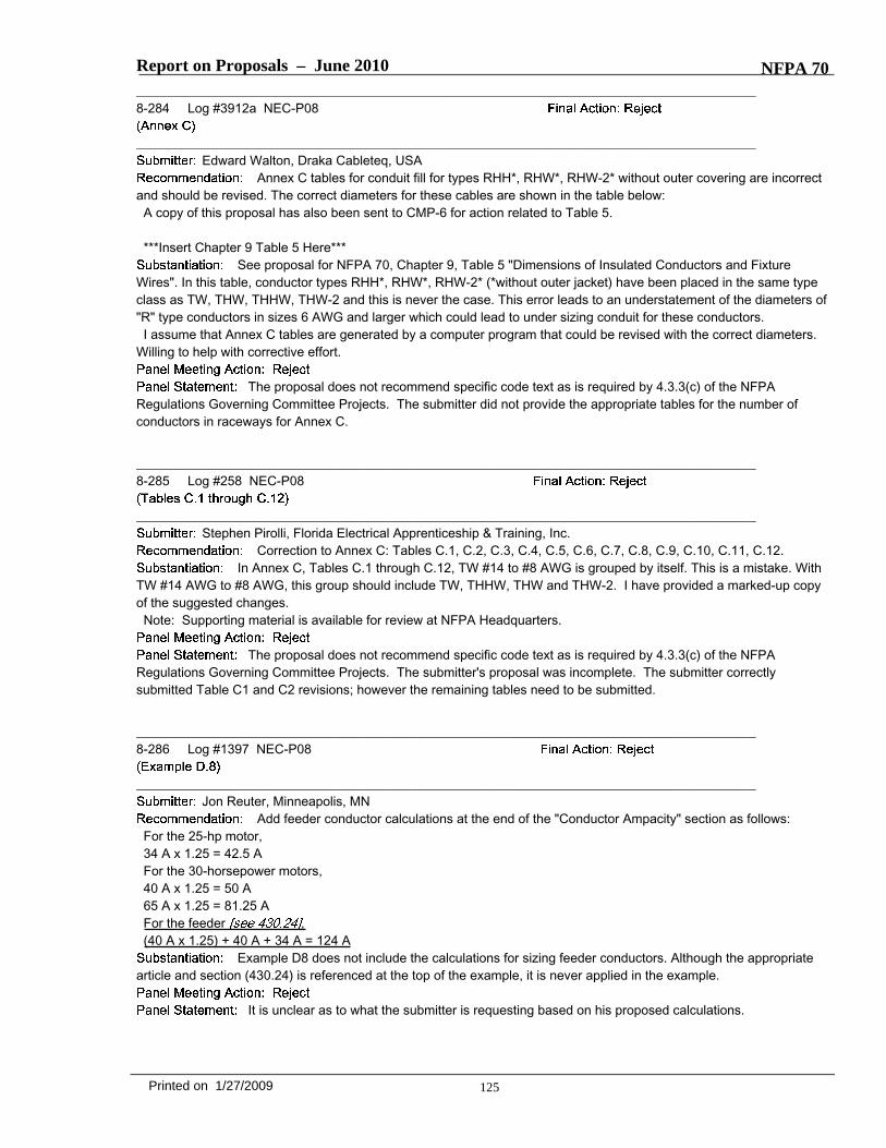
Report on Proposals – June 2010 NFPA 70_______________________________________________________________________________________________8-284 Log #3912a NEC-P08
_______________________________________________________________________________________________Edward Walton, Draka Cableteq, USA
Annex C tables for conduit fill for types RHH*, RHW*, RHW-2* without outer covering are incorrectand should be revised. The correct diameters for these cables are shown in the table below:A copy of this proposal has also been sent to CMP-6 for action related to Table 5.
***Insert Chapter 9 Table 5 Here***See proposal for NFPA 70, Chapter 9, Table 5 "Dimensions of Insulated Conductors and Fixture
Wires". In this table, conductor types RHH*, RHW*, RHW-2* (*without outer jacket) have been placed in the same typeclass as TW, THW, THHW, THW-2 and this is never the case. This error leads to an understatement of the diameters of"R" type conductors in sizes 6 AWG and larger which could lead to under sizing conduit for these conductors.I assume that Annex C tables are generated by a computer program that could be revised with the correct diameters.
Willing to help with corrective effort.
The proposal does not recommend specific code text as is required by 4.3.3(c) of the NFPARegulations Governing Committee Projects. The submitter did not provide the appropriate tables for the number ofconductors in raceways for Annex C.
_______________________________________________________________________________________________8-285 Log #258 NEC-P08
_______________________________________________________________________________________________Stephen Pirolli, Florida Electrical Apprenticeship & Training, Inc.
Correction to Annex C: Tables C.1, C.2, C.3, C.4, C.5, C.6, C.7, C.8, C.9, C.10, C.11, C.12.In Annex C, Tables C.1 through C.12, TW #14 to #8 AWG is grouped by itself. This is a mistake. With
TW #14 AWG to #8 AWG, this group should include TW, THHW, THW and THW-2. I have provided a marked-up copyof the suggested changes.Note: Supporting material is available for review at NFPA Headquarters.
The proposal does not recommend specific code text as is required by 4.3.3(c) of the NFPARegulations Governing Committee Projects. The submitter's proposal was incomplete. The submitter correctlysubmitted Table C1 and C2 revisions; however the remaining tables need to be submitted.
_______________________________________________________________________________________________8-286 Log #1397 NEC-P08
_______________________________________________________________________________________________Jon Reuter, Minneapolis, MN
Add feeder conductor calculations at the end of the "Conductor Ampacity" section as follows:For the 25-hp motor,34 A x 1.25 = 42.5 AFor the 30-horsepower motors,40 A x 1.25 = 50 A65 A x 1.25 = 81.25 AFor the feeder ,(40 A x 1.25) + 40 A + 34 A = 124 A
Example D8 does not include the calculations for sizing feeder conductors. Although the appropriatearticle and section (430.24) is referenced at the top of the example, it is never applied in the example.
It is unclear as to what the submitter is requesting based on his proposed calculations.
125Printed on 1/27/2009

Report on Proposals – June 2010 NFPA 70_______________________________________________________________________________________________8-287 Log #4299 NEC-P08
_______________________________________________________________________________________________Robert Crain, Cablofil
Add sample calculations for cable tray fill to a new or existing Annex.
***Insert Example Calculations Here***
The rules and charts provided in Article 392 for determining the required cable tray size are complex.Cable tray manufacturers receive many technical support inquiries regarding how to figure cable tray size. Locatingsample calculations in an Annex would assist users of the Code in sizing cable tray.A table in an Annex of the Code would be a useful tool, and additionally these sample calculations will provide the
detail necessary to understand the application of alternate cable types and sizes.
Add a new title to the proposal to state:
The panel supports the proposal but requires a title per the NEC Style Manual.
_______________________________________________________________________________________________8-289 Log #3708 NEC-P08
_______________________________________________________________________________________________Vince Baclawski, National Electrical Manufacturers Association (NEMA)
Add table for cable tray fill to a new Annex.
***Insert Tables 1-7 Here***
The tables for sizing cable tray based on the type and number of conductors is very confusing anddifficult to understand. The rules are hard to apply correctly even for an experienced user. Tables showing the numberof conductors in each size tray, similar to Annex C in NFPA 70 is much simpler and straightforward. The number onerequest of cable tray manufacturers’ technical support is for information concerning the correct sizing of cable tray basedon a fixed number of cables. Many cable tray manufacturers have developed charts or spreadsheets to try and assistthe contractor with sizing tray and some do not always give the correct answers. Inspectors also have difficultydetermining the correct number of cables for an installed cable tray. The tables proposed to be added to new Annex aredesigned to reduce errors and provide the contractor the ease of use similar in design and style to those currentlylocated in Annex C.The information used to generate the tables is contained within the 2008 NFPA 70. The formulas used are based on
the cable types, ampacities and sizes as required in NEC section 392.9 and 392.11. The tables are based on singleconductor diameters currently located in NFPA 70, Chapter 9 Table 8. Multi-conductor cable diameters are based onworst case diameters reviewed from each all North American Copper/Aluminum multiconductor cable manufacturers.The inside width and fill depth of cable tray is restricted by NEMA VE1 as referenced in NEC 392.1. The proposedcable tray tables have the most common combination of cable types and conductors. It will serve as guideline for thetypical cable tray installation and will allow the less common installation to continue to rely on the formulas in the existingcode.
The panel found errors in the table; technical information is not correct.
126Printed on 1/27/2009
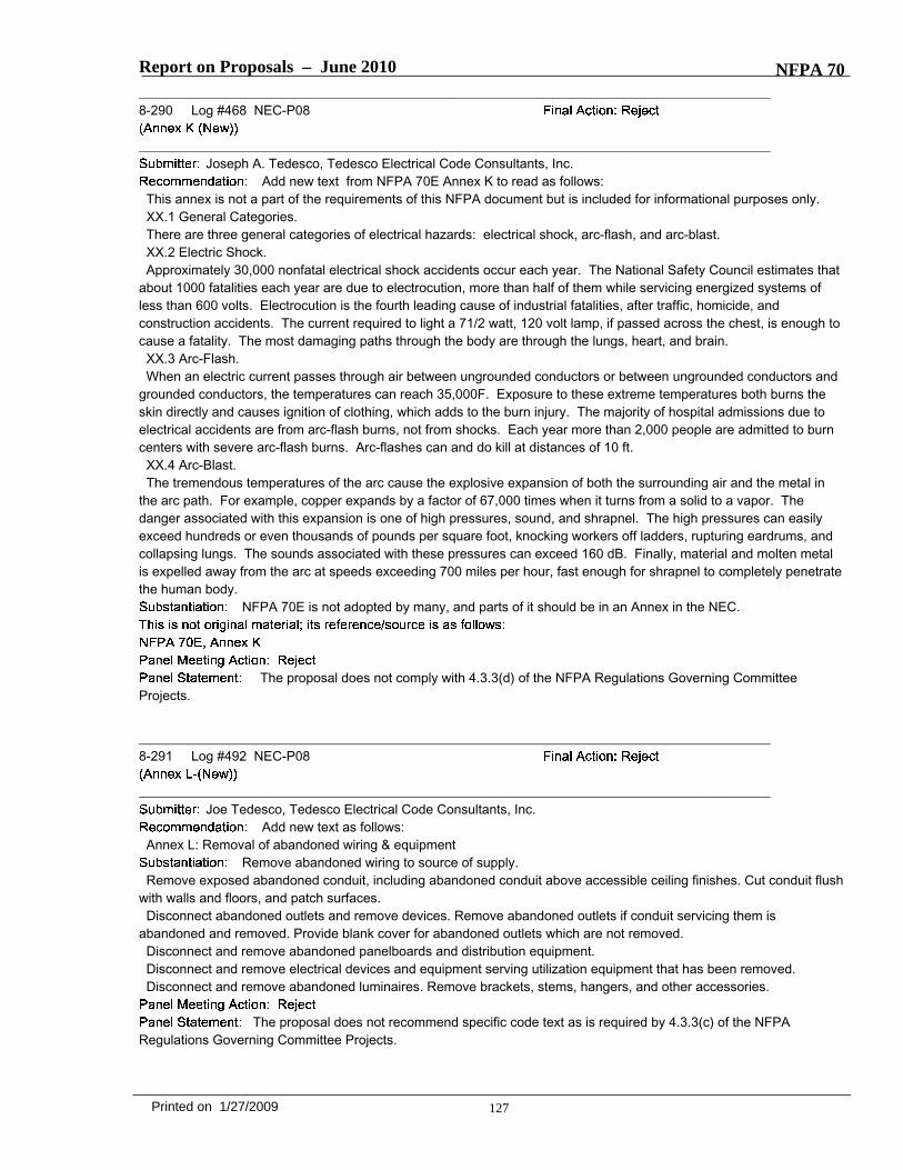
Report on Proposals – June 2010 NFPA 70_______________________________________________________________________________________________8-290 Log #468 NEC-P08
_______________________________________________________________________________________________Joseph A. Tedesco, Tedesco Electrical Code Consultants, Inc.
Add new text from NFPA 70E Annex K to read as follows:This annex is not a part of the requirements of this NFPA document but is included for informational purposes only.XX.1 General Categories.There are three general categories of electrical hazards: electrical shock, arc-flash, and arc-blast.XX.2 Electric Shock.Approximately 30,000 nonfatal electrical shock accidents occur each year. The National Safety Council estimates that
about 1000 fatalities each year are due to electrocution, more than half of them while servicing energized systems ofless than 600 volts. Electrocution is the fourth leading cause of industrial fatalities, after traffic, homicide, andconstruction accidents. The current required to light a 71/2 watt, 120 volt lamp, if passed across the chest, is enough tocause a fatality. The most damaging paths through the body are through the lungs, heart, and brain.XX.3 Arc-Flash.When an electric current passes through air between ungrounded conductors or between ungrounded conductors and
grounded conductors, the temperatures can reach 35,000F. Exposure to these extreme temperatures both burns theskin directly and causes ignition of clothing, which adds to the burn injury. The majority of hospital admissions due toelectrical accidents are from arc-flash burns, not from shocks. Each year more than 2,000 people are admitted to burncenters with severe arc-flash burns. Arc-flashes can and do kill at distances of 10 ft.XX.4 Arc-Blast.The tremendous temperatures of the arc cause the explosive expansion of both the surrounding air and the metal in
the arc path. For example, copper expands by a factor of 67,000 times when it turns from a solid to a vapor. Thedanger associated with this expansion is one of high pressures, sound, and shrapnel. The high pressures can easilyexceed hundreds or even thousands of pounds per square foot, knocking workers off ladders, rupturing eardrums, andcollapsing lungs. The sounds associated with these pressures can exceed 160 dB. Finally, material and molten metalis expelled away from the arc at speeds exceeding 700 miles per hour, fast enough for shrapnel to completely penetratethe human body.
NFPA 70E is not adopted by many, and parts of it should be in an Annex in the NEC.
The proposal does not comply with 4.3.3(d) of the NFPA Regulations Governing CommitteeProjects.
_______________________________________________________________________________________________8-291 Log #492 NEC-P08
_______________________________________________________________________________________________Joe Tedesco, Tedesco Electrical Code Consultants, Inc.
Add new text as follows:Annex L: Removal of abandoned wiring & equipment
Remove abandoned wiring to source of supply.Remove exposed abandoned conduit, including abandoned conduit above accessible ceiling finishes. Cut conduit flush
with walls and floors, and patch surfaces.Disconnect abandoned outlets and remove devices. Remove abandoned outlets if conduit servicing them is
abandoned and removed. Provide blank cover for abandoned outlets which are not removed.Disconnect and remove abandoned panelboards and distribution equipment.Disconnect and remove electrical devices and equipment serving utilization equipment that has been removed.Disconnect and remove abandoned luminaires. Remove brackets, stems, hangers, and other accessories.
The proposal does not recommend specific code text as is required by 4.3.3(c) of the NFPARegulations Governing Committee Projects.
127Printed on 1/27/2009


![Report on Proposals — Copyright, NFPA NFPA 11 · PDF fileReport on Proposals — Copyright, NFPA NFPA 11 ... ExxonMobil Corporation, VA [U] ... Report on Proposals — Copyright,](https://img.pdfslide.us/doc/110x75/5ab72e787f8b9a2f438e8027/report-on-proposals-copyright-nfpa-nfpa-11-on-proposals-copyright-nfpa.jpg)