Embed Size (px)
Citation preview

238 Franklin Institute.
100 to 1. A London firm employed to print stamps for the Government, is in the habit of using raised copper surfaces for the purpose, no less than 125,000,OOO impressions have been taken from one of their plates. The density of the copper used in the manufacture of type is considerably in- creased by the compression which it undergoes by the machinery of M. Petit. The machine produces thirty-two types per minute; and it would be difficult to exceed the typographic neatness of the character. Speci- mens of the type and printing were distributed among those present.
Land. Athen., June 2, 1849.
Quantity of Ammonia in Atmospheric Air.
By a series of well-conducted experiments, M. Fresenius has determined that 1 ,OO?,OOO parts of atmospheric air contains during the day 0.098 parts of ammonra, equal to O-283 parts of carbonate of ammonia. During the night the same amount of air contains 0.169 ammonia, equal to 0.474 car- bonate of ammonia. These results are known to be slightly in error, there being actually more ammonia in the air; they are, however, the closest ap- proximations which have been made. Ibid. June 23,1849.
For the Journal of the Franklin Institute.
It being the intention of persons in the direction of the construction of water works, to add a considerable expense in placing the pumps under the surface of the water to be raised, the writer is desirous of knowing what advantages will accrue in this arrangement, theoretical or practical, over the operation of pumps placed say five feet above the surface.
If any of the scientific readers of the Journal will bekind enough to give their opinion and reasons, and, if possible, data proving advantages, they will confer a favor upon a learner. A. B.
Philadelphia, .&gust 25, 1849.
FRANKLIN INSTITUTE.
COMMITTEE ON SCIENCE AND THE ARTS.
Report on AI. Wlleroi’s .h%~ Surveying bdrument. The Committee on Science and the Arts, constituted by the Franklin Institute of the State
of Pennsylvania, for the Promotion of the Mechanic Arts, to whom was referred for ex- amination-“A new Surveying Instrument,” invented by M. Villeroi-
REPORT:-
That this instrument is intended to give the distances between the sta- tions by means of a single observation through the instrument, without the necessity of using a chain or any other measuring apparatus.
Report on JK Villeroi’s .iYew Surveying Instrument. 239
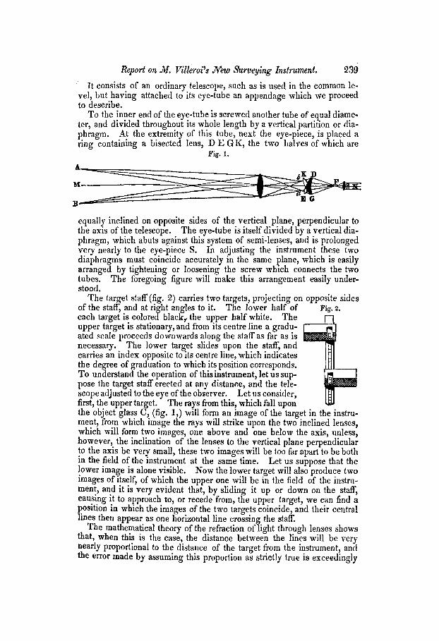
It consists of an ordinary telescope, such as is used in the common le- vel, but having attached to its eye-tube an appendage which we proceed to describe.
To the inner end of the eye-tube is screwed another tube of equal diame- ter, and divided throughout its whole length by a vertical partition or dia- phragm. At the extremity of this tube, next the eye-piece, is placed a ring containing a bisected lens, D E GK, the two halves of which are
Fig. 1.
equally inclined on opposite sides of the vertical plane, perpendicular to the axis of the telescope. The eye-tube is itself divided by a vertical dia- phragm, which abuts against this system of semi-lenses, and is prolonged very nearly to the eye-piece S. In adjusting the instrument these two diaphragms must coincide accurately in the same plane, which is easily arranged by tightening or loosening the screw which connects the two tubes. stood.
The foregoing figure will make this arrangement easily under-
The target staff (fig. 2) carries two targets, projecting on opposite sides of the staff, and at right angles to it. The lower half of each target is colored black,, the upper half white. The upper target is stationary, and from its centre line a gradu- ated scale proceeds downwards along the staff as far as is necessary. The lower target slides upon the staffI; and carries an index opposite to its centre line, which indmates the degree of graduation to which its position corresponds. To understand the operation of thisinstrument, let us sup- pose the target staff erected at any distance, and the tele- scope adjusted to the eye of the observer. Let us consider, first, the upper target. the object glass C, (fig.
The rays from this, which fall upon 1,)
Fig. 2.
ment, from which image the will form an image of the target in the instru- rays mill strike upon the two inclined lenses,
which will form two images, one above and one below the axis, unless, however, the inclination of the lenses to the vertical plane perpendicular to the axis be very small, these two images will be too far apart to be both in the field of the instrument at the same time. lower image is alone visible.
Let us suppose that the Now the lower target will also produce two
images of itself, of which the upper one will be in the field of the instru- menf, and it is very evident that, by sliding it up or down on the staff, causmg it to approach to, or recede from, the upper target, we can find a position in which the images of the two targets coincide, and their central lines then appear as one horizontal line crossin the staff.
The mathematical theory of the refraction of 7 ight through lenses shows that, when this is the case, the distance between the lines will be very nearly proportional to the distance of the target from the instrument, and the error made by assuming this proportion as strictly true is exceedingly

240 Frahktin Instihde.
small in any case, and diminishes as the distance increases, and at reason- able distances will be within the probable error of observation.
If, therefore, any instrument of this kind be placed at one extremity of a carefully measured line, and the distance between the targets at the other extremity be ascertained when the images of the centre lines coincide, this distance, divided into equal parts, will furnish the graduated scale neces- sary for the instrument.
The accuracy of the work performed hy this instrument will depend, as well upon the care in determining the exact point at which the two lines coincide, as upon the precision with which the reading of the scale is ef- fected . The rodman will, therefore, have a greater responsibility thrown upon him than at present, from which, however, the surveyor may relieve him by inspecting the staff himself previous to its removal from its station. Neither observation, however, is difficult, and the Committee do not be- lieve that any practical difficulty will be found to arise from them.
The greater rapidity with which work can be done by this instrument presents a very great advantage, and the Committee think that, under cer- tain circumstances, such as surveying in rocky, bushy, or swampy grounds, it will be found very valuable. It also allows the easy determination of distances in places where direct measurement is impossible, such as across broad sheets of water.
The Committee, therefore, believe the instrument of M. ViIleroi to be a valuable addition to our surveying apparatus.
By order of the Committee,
WILLIAM HAMILToK, Jlctuary. Philadelphia, April 12th, 1849.
Report on the Catoptric, Dioptric, and Catadioptric Systems of Lights for Lighthouses.
Appendix containing the Notes referred to in the Report. Continued from page 166.
NOTE 3. Report of I. W. P. Lewis; alsq, the Annuaire! by Arago; the Report to the British Parliament of 1845? with the appendix to the same, and the Notes of Stevenson, all before cited.
Also, Report of the Committee of the Royal Society of Edinburgh, Prof. Forbes, Reporter, (cited in dot. 138 and 258, previously cited, also page 60 of dot. 488, previously cited.) The Committee were Greenock, Robin- son, Trail, Christison, and Forbes.
Also, Letter from Leonor Fresnel, (not the inventor of the Fresnel Iights,) the Secretary, to the Commissioners of Lights, (France,) 31st December, 1845, in dot. 488, previously cited.
Extract from page 118 of this documed., COMPARISON OF THE TWO SYSTEMS OF LIGHTS.
[Parallel between the Catoptric and Dioptric Lights.]
I wili consider the two systems under the following heads:-


![UNIT I 1. What is the difference between plane surveying ... · Write any two principles of surveying [M/J-13,M/J-15] The two basic principles of surveying are: a) To work ... Following](https://img.pdfslide.us/doc/110x75/5ac29caf7f8b9ad73f8e4ee2/unit-i-1-what-is-the-difference-between-plane-surveying-any-two-principles.jpg)