Embed Size (px)
Citation preview

Report on M S Ramaiah Institute of Technology’s participation at IGVC
2014 Faculty Advisor Declaration
This is to certify that the design and the implementation of the vehicle by the current student team
has been significant and can be awarded credit in a senior degree course. The current student
team has made significant improvements to the hardware and software design as compared to the
previous year’s team.
Dr. S. Sethu Selvi
Faculty Advisor

Page 1
Contents
1) Introduction……………………………………………………2
2) Team Structure………………………………………………..2
3) Design approach………………………………………………3
a. Planning…………………………………………………….3
b. Design………………………………………………………3
c. Implementation……………………………………………..3
d. Integration…………………………..………………………3
e. Testing……………………………………………………...3
4) Design Innovation…………………………………….……….4
a. Mechanical Design Overview……………….……..4
b. Power supply board………………………….……..5
c. Computer Vision…………………………….……..5
Lane detection……………………………….……..5
Obstacle Avoidance………………………….…….7
Computer Vision Interfacing………………….…...7
d. Waypoint Navigation………………………….…...7
GPS Evaluation Kit…………………………….…..7
Digital Compass……………………………….…...9
5) System Interfacing………………………………….………..11
6) Performance Estimation……………………………….……12
7) Cost Estimate………………………………………………...12
8) Conclusion……………………………………………………12
9) Acknowledgment………………………………………...…..13
Page 2
Introduction
The robotics team of M. S. Ramaiah Institute of Technology presents Moksha-4 UGV for the prestigious event IGVC (Intelligent Ground Vehicle Competition), which will be held at Oakland University in Rochester, Michigan on June 6 - June 9, 2014. This year the team Moksha-4 is trying to bring out a vehicle which is an improvised version of the previous one with respect to the technology used and the body design. The vehicle will be designed by a collaborative effort from a multidisciplinary ten member team.
Team Structure
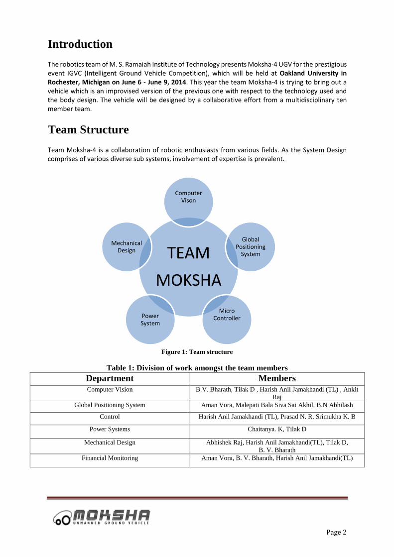
Team Moksha-4 is a collaboration of robotic enthusiasts from various fields. As the System Design comprises of various diverse sub systems, involvement of expertise is prevalent.
Figure 1: Team structure
Table 1: Division of work amongst the team members
Department Members Computer Vision B.V. Bharath, Tilak D , Harish Anil Jamakhandi (TL) , Ankit
Raj
Global Positioning System Aman Vora, Malepati Bala Siva Sai Akhil, B.N Abhilash
Control Harish Anil Jamakhandi (TL), Prasad N. R, Srimukha K. B
Power Systems Chaitanya. K, Tilak D
Mechanical Design Abhishek Raj, Harish Anil Jamakhandi(TL), Tilak D,
B. V. Bharath
Financial Monitoring Aman Vora, B. V. Bharath, Harish Anil Jamakhandi(TL)
TEAM
MOKSHA
Computer Vison
Global Positioning
System
Micro ControllerPower
System
Mechanical Design

Page 3
Design Approach
The process of building the UGV started with the team understanding the rules and the challenges of the
competition, understanding the level of competition from other countries and how the project will be able to satisfy
all the requirements. After analysis of the rules and the challenges of the competition, the design requirements of
the project were finalized and the optimal components required for the development of the UGV were selected.
The project progression can be split into six stages: planning, design, implementation, integration and testing. We
have used the spiral method of development, where in sufficient time has been allotted to planning, design,
implement and testing of the components and the system on the whole.
The following segment illustrates these stages in detail:
Planning:
Every system in engineering requires planning and this project is no exception.
Planning consists of:
1) Recruiting robotics enthusiasts.
2) Discussing the competition rules.
3) Dividing the task and identifying individual expertise and allotting the appropriate task.
4) Setting deadlines for the stages.
Design:
This stage consisted of a lot of research in order to find the right solution for the objectives specified. All the sub
teams were encouraged to go ahead and work on their fields and come up with as many propositions as possible.
Development of algorithms, identification of the right components and architecture of the UGV marked the
successful completion of this stage.
Implementation:
Once the components to be used, algorithms to be deployed are documented, next task was to implement the
proposed plan. The sub teams implemented their propositions independently and hence could extract the pros and
cons of their conception.
Integration:
Once the individual components were developed and their independent working were confirmed, it was then put
together and their functioning as a system was evaluated. The inter-component communication was established
using a master program which was developed and the data flow between the components were observed.
Testing:
Once the UGV was ready with the basic operations, it was then tested on field. The outputs were analysed and the
system design were iteratively modified in order to satisfy the competition specification.

Page 4
Design Innovations
1. Mechanical Design Overview:
The main chassis was manufactured using iron tubes. These provide high strength to weight ratio for very low
cost. A T-tower has been built on the chassis. This tower houses all the view sensors, providing them with
unobstructed view of the sensors. The freewheeling castor is attached to a cantilever to increase the wheelbase
and thus the stability.
The main goal of the mechanical design is to provide a versatile platform such that the hardware and software can
work in unison. Moksha-4 uses a single-frame construction thus enabling reusability, upgradability, better stability
for sensors and multi-terrain manoeuvrability
Figure 2: a) and b) Isometric view c) front view d) side view

Page 5
2. Power Supply Board:
Power consumption of the motor is rated at 240 watts with current rating of 10 Amps. Maximum voltage tolerance
level of the motor is 24 Volts. Therefore according to the motor driving requirements, a high power motor driver
MOSFET H-bridge was designed to drive large DC brushed motors. The versatility of this driver makes it
suitable to a large range of current and voltage. It can deliver up to 10 A of continuous current with a small board
size and no required heat sink. The logic connections are designed to interface with 5V systems. Here the logic
command is given through a microcontroller. The motor speed can be varied through PWM commands. The motor
driver supports PWM frequencies as high as 40 kHz, though higher frequencies result in higher switching losses
in the motor driver.
Figure 3: Power Supply Board Schematic
3. Computer Vision System Design:
Team Moksha-4 has an ingenuous computer vision approach divided into
Lane detection.
Obstacle Avoidance.
i. Lane Detection
The images are continuously acquired from the video captured by the two USB cameras (Left and Right) and are
processed using different image processing steps to detect the lane. The cameras are placed at an angle (of about
60 degrees w.r.t horizontal plane) facing the ground at the extreme ends of the vehicle. This is done to avoid any
unnecessary subjects being detected due to large frame of view.
The presence of the lane is detected from the final processed image of the two cameras by scanning them for large
chunks of white pixels (which represent the lane) and instructions are sent appropriately to avoid them.

Page 6
Algorithm flow of the lane is as followed:
Figure 4: Lane detection design flow

Page 7
ii. Obstacle Avoidance :
The vehicle is equipped with a bumblebee stereo camera. It is used as a stereo measurement equipment and is
used to measure the depth of the obstacle with respect to the vehicle. This device returns a disparity of the images
from the left and right camera. Then, the same is subjected to an analysis algorithm where image is gridded and
based on the location of the obstacle with respect to the vehicle frame of view, the vehicle is commanded.
The algorithm flow is as indicated below:
Figure 5: Obstacle Avoidance Algorithm Flow and disparity map indicating obstacle with reduced noise
iii. Computer Vision Interface:
s
The vision systems are interfaced based on the dynamic priority where in the lane is alerted with a distance range
of .75mtr and an occurrence of obstacle is alerted at a distance of 2mtr with respect to the vehicle.
4. Waypoint Navigation:
The navigation of the vehicle is achieved through the use of a GPS evaluation kit and a digital compass.
i. GPS Evaluation Kit
The Vehicle makes use of the Ublox EVK 7P GPS Evaluation kit. This is used to receive standard NMEA 0183
GPS strings through the USB V2.0 port. The kit enables sub meter accuracy with precise positioning. With the
integration of the microcontroller and HMC5883L digital compass module, the vehicle successfully achieves
waypoint navigation. The two NMEA strings used are the:
$GPRMC for extracting the current positional validity status (i.e., ‘A’ or ‘V’), latitude and longitude.
$GPGGA for extracting the Horizontal Dilution of Precision (HDOP).
Page 8
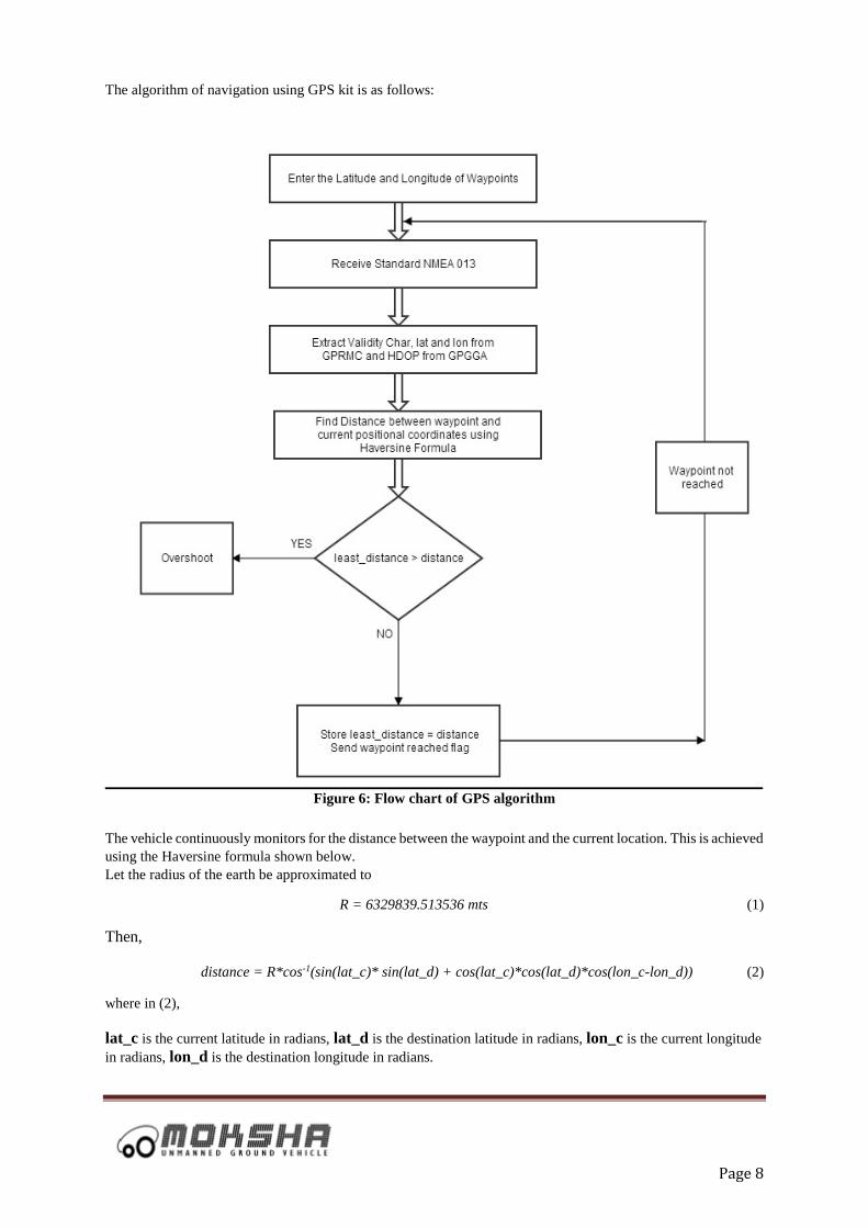
The algorithm of navigation using GPS kit is as follows:
Figure 6: Flow chart of GPS algorithm
The vehicle continuously monitors for the distance between the waypoint and the current location. This is achieved
using the Haversine formula shown below.
Let the radius of the earth be approximated to
R = 6329839.513536 mts (1)
Then,
distance = R*cos-1(sin(lat_c)* sin(lat_d) + cos(lat_c)*cos(lat_d)*cos(lon_c-lon_d)) (2)
where in (2),
lat_c is the current latitude in radians, lat_d is the destination latitude in radians, lon_c is the current longitude
in radians, lon_d is the destination longitude in radians.

Page 9
The vehicle is initially made to align towards the waypoint by turning using the digital compass. Then it moves
towards it, while calculating the distance each time. A waypoint is once reached when the vehicle is within a
minimal error. The heading and positional coordinates of the next waypoint are immediately updated.
Least distance is the minimum distance calculated up to the preceding estimation. If the present distance calculated
decreases, the vehicle approaches the waypoint. If the distance calculated is greater than the least distance, then
the vehicle has overshot or gone farther away from the waypoint. As shown in the flowchart, a case of ‘Overshoot’
is accounted for. This case recalculates the heading to the waypoint and the required distance to traverse along the
path to reach it.
Error in angle calculation and distance calculation are prominent in navigation systems. For large distances, the
slightest error in the calculation of heading can result in a positional error as shown in the figure below. Point A
is the point of overshoot and point B is the point where the vehicle realizes the occurrence of an overshoot. Hence
the heading is updated to point towards the waypoint.
Figure 7: Graphical Description of Waypoint Navigation
ii. Digital Compass
For achieving the correct heading towards the waypoint, the 3-axis digital compass IC HMC5883L is being used.
The HMC5883L is 3.0x3.0x0.9mm surface mount 16-pin leadless chip carrier (LCC).
The HMC5883L includes high resolution HMC118X series magneto-resistive sensors plus an ASIC containing
amplification, automatic degaussing strap drivers, offset cancellation, and a 12-bit ADC that enables 1o to 2o
compass heading accuracy. The HMC5883L utilizes Honeywell’s Anisotropic Magneto resistive (AMR)
technology that provides advantages over other magnetic sensor technologies. These anisotropic, directional
sensors feature precision in-axis sensitivity and linearity. These sensors’ solid state construction with very low
axis sensitivity is designed to measure both the direction and the magnitude of Earth’s magnetic fields, from milli-
gauss to 8 gauss. Communication with the HMC5883L is done through an I2C interface. The I2C interface
requires just two wires for communication, one for a clock (SCL), and one for data (SDA).

Page 10
Figure 8: HMC5883L Digital Compass
The following is flow chart for whole process and with the following process, the concept of overshot as
explained before is also used.
Figure 9: Flow chart of the compass algorithm

Page 11
System Interfacing
The collaboration between different modules is depicted in Fig. 10. The processing unit perceives its surroundings
with the help of the following sensors: two USB cameras, Bumblebee stereo camera, a GPS module and a digital
compass. The two cameras give the vehicle a view of the lanes in the front. Bumblebee camera gives the vehicle
a stereo depth view of the frontal obstacles. The GPS module gives the distance in order to reach the destination
waypoint.
The computer vision algorithm work in tandem to give all possible routes avoiding the obstacles and keeping the
vehicle within the lane. Upon the possibility of multiple choices, GPS algorithm prioritizes the desired choice.
However, upon the occurrence of a single choice, computer vision is allocated the highest priority as compared to
GPS. This technique of switching between the priorities among the various sub systems dynamically is called as
Dynamic Priority Allocation (DPA). The combined signal is fed to the motor controller for movement of the
vehicle.
Figure 10: System Interface Description

Page 12
Performance Estimate
Speed: The vehicle uses two high torque Motion Tech DC brushed motors with a gear ratio of 25:1, individually.
Diameter of the rear wheel is 32 cm and that of the front wheel is 21.5 cm. The tested speed of the vehicle with
load is approximately 2.5 mph (75 rpm) and without load is 4 mph (100 rpm).
Ramp Climbing Ability: The ramp tests reveal that the vehicle stalls at an angle of 40 degrees and thus can
ascend inclinations as per the IGVC standards.
Distance of Alert: The vehicle will be commanded about the obstacle at a distance of 2mtr and can also be
dynamically set based on the users need. With respect to the lane the vehicle will be alerted at a distance of .75mtr
before with respect to the vehicle.
Cost Estimate
Table 2: Cost Estimate chart with actual cost and cost to team Device Quantity Actual cost
(INR)
Cost to team Comments
Bumblebee camera 1 41,299 0 Sponsored by Honeywell
India Pvt Ltd
Cameras 2 1700 1700 -
GPS 1 23000 23000 -
Compass 1 500 500 -
Chassis 1 20000 0 Sponsored by Ostrich
Mobility
Motor 2 36000 0 Sponsored by Ostrich
Mobility
Motor Controller 2 800 800 -
Microcontroller 1 700 700 -
Battery 1 4000 0 Previously owned
Miscellaneous - 6000 6000 -
Grand Total 1,33,999 32,700 -
In Dollars the total Cost of the project Moksha-4 is $2,233.31, cost to team is $545
Conclusion
MOKSHA-4 has been a stepping stone for an engineering mind. It has proven to be very efficient and reliable,
performing well while driving on any kind of terrain. The new algorithms developed along with the updated
hardware technology shows promising results, and the MSRIT team has great confidence going into this year's
competition.

Page 13
Acknowledgement
Team MOKSHA-4 would like to acknowledge and commemorate all of its team members, our project guide Dr.
S. Sethu Selvi, the EC Department staff, the Mechanical Engineering staff, the Alumni Association of M.S.
Ramaiah Institute of Technology, the Chief Executive, and the Principal of the Institution for all of their support,
help and immense encouragement. We also would like to give special mention to Mr. Hari Vasudevan (Managing
Director, Ostrich Mobility Pvt. Ltd.) and Dr. Eswara Lalitha for their technical help and support. We would also
like to thank our seniors Nishcal K.N, Naveen R. Iyer, Nitin J.Sanket and Nitish S. Prabhu for their immense
support and motivation. Finally, we would also like to thank the organizers of IGVC for giving us an opportunity
to showcase our skills.


![[SOFTWARE DESIGN FOR IGVC COMPETITON ]](https://img.pdfslide.us/doc/110x75/61dab469fc8c63207126e873/software-design-for-igvc-competiton-.jpg)