Embed Size (px)
Citation preview

E-DTMB technical trial report 1 of 28
Report on Enhanced Digital Terrestrial
Multimedia Broadcast (E-DTMB) system
technical trial
in Hong Kong Science Park, Shatin
Trial period 1st August 2011 to 31st December 2011
Version 1.0
Issued 03 January 2012
Prepared by Hong Kong Applied Science and Technology Research
Institute Company Ltd. (ASTRI)
E-DTMB technical trial report 2 of 28
TABLE OF CONTENTS
ACKNOWLEDGEMENTS ........................................................................................................................................4
ACRONYMS AND ABBREVIATIONS ....................................................................................................................5
REFERENCES ............................................................................................................................................................5
1 INTRODUCTION ...............................................................................................................................................6
2 SCOPE OF E-DTMB FIELD TRIAL................................................................................................................7
3 TEST SITE DESCRIPTION AND SYSTEM SETUP......................................................................................8
3.1 TEST SITE LOCATION .......................................................................................................................................8 3.2 TRANSMISSION PARAMETERS........................................................................................................................10 3.3 TRANSMITTER SETUP ....................................................................................................................................10 3.4 RECEIVER SETUP...........................................................................................................................................12 3.5 INTERFERENCE CONDITION ...........................................................................................................................15
4 MEASUREMENT LOCATIONS.....................................................................................................................16
5 MEASUREMENT RESULTS...........................................................................................................................18
5.1 STATIONARY RECEPTION: CLASS A - OUTDOOR RECEPTION...........................................................................18 5.2 MOBILE RECEPTION ......................................................................................................................................19
5.2.1 Class C - mobile reception with external vehicle-roof antenna .............................................................20 5.2.2 Class D - mobile reception with in-vehicle antenna ..............................................................................20
6 DISCUSSION.....................................................................................................................................................22
APPENDIX A MEASUREMENT RECORDS FOR RECEPTION CLASS A..................................................23
RECORD FOR S1........................................................................................................................................................23 RECORD FOR S2........................................................................................................................................................25 RECORD FOR S3........................................................................................................................................................26 RECORD FOR S7........................................................................................................................................................27 RECORD FOR S8........................................................................................................................................................27 RECORD FOR S9........................................................................................................................................................28

E-DTMB technical trial report 3 of 28
LIST OF FIGURES
Figure 1: Aerial view of the Hong Kong Science Park, Shatin. Location of the transmit antenna is highlighted. (The
satellite image was taken from Google Map.) .......................................................................................................8
Figure 2: Different view to / from the Tx site at JL Demo Room in East wing of Lakeside 2 building. .......................9
Figure 3: Transmitter site - JL Demo Room, ASTRI office.........................................................................................10
Figure 4: Photograhs of transmission equipment fo the Phase 1a of E-DTMB field trial. ..........................................11
Figure 5: Block diagram of the transmitter setup for the of E-DTMB field trial.........................................................12
Figure 6: Receiving antennas, a) omni-directional; b) tuned dipole and c) mini antenna............................................13
Figure 7: TVB survey vehicle: a) photograph and b) a sketch of its interior. ..............................................................14
Figure 8: Reception equipment carrying trolley. The E-DTMB demodulator and a mini LCD TV the upper tray and
the notebook computer on the lower tray.............................................................................................................14
Figure 9: Block diagram of the rceiver setup for the E-DTMB field trial. ..................................................................15
Figure 10: Analog TV spectrum at Ch59: a) captured at JL Demo Room, 3/F Lakeside building and b) at ground
level on Science Park East Avenue. .....................................................................................................................15
Figure 11: Distribution of measurement points. (The satellite image was taken from Google Map.) .........................16
Figure 12: Science Park East Avenue. Photographs taken at test point S1. .................................................................17
Figure 13: Measurement result for reception class C. Received video qualtiy was highlighted by different colours
along the test route. (The satellite image was taken from Google Map.) ............................................................20
Figure 14: Measurement result for reception class D. Received video qualtiy was highlighted by different colours
along the test route. (The satellite image was taken from Google Map.) ............................................................21
LIST OF TABLES
Table 1: Specification of the transmitter site. .................................................................................................. 10
Table 2: E-DTMB transmission parameters. ................................................................................................... 10
Table 3: Equipment list for the transmitter. ......................................................................................................11
Table 4: Equipment list for the reception. ....................................................................................................... 12
Table 5: Propagation profiles of test routes and stationary test points............................................................. 16
Table 6: Measurement results for the reception class A on Science Park East Avenue. .................................. 18
Table 7: Measurement results for the reception class A on Pak Shek Kok Promenade. .................................. 19
E-DTMB technical trial report 4 of 28
Acknowledgements
Particular acknowledgement is given to Television Broadcasts Limited (TVB) for lending the transmit
antenna system, reception equipment and engineering resources. Thanks are also due to Tsinghua University
for providing the E-DTMB transmitter / receiver, power amplifier and engineering resources.
E-DTMB technical trial report 5 of 28
Acronyms and Abbreviations
COR Centre of radiation
DTMB Digital terrestrial/television multimedia broadcast
E-DTMB Enhanced DTMB
ERP Effective radiated power
HKSP Hong Kong Science Park
LOS Line-of-sight
MER Modulation error ratio
mph Miles per hour
NLOS Non line-of-sight
RF Radio frequency
SNR Signal-to-noise ratio
STB Set-top box
TS Transport stream
References
[1] GB 20600-2006, Framing structure, channel coding and modulation for digital television terrestrial broadcasting system, 2006.
[2] X. Wang, et al, “Embedded transmission of multi-service over DTMB system”, IEEE Trans. Broadcasting, pp. 504-513, December 2010.
[3] Rohde&Schwarz, Broadcast test system R&S SFU: specifications, v4.00, March, 2006.
[4] Radio Frequency Systems (FRS), Technical data sheet: 470-860 MHz TV panel arrays - PVP series, July, 2010.
[5] Radio Frequency Systems (FRS), Applications guide: PVP panel array antennas - Band IV/V (UHF) TV panel arrays, August, 2010.
[6] Rohde&Schwarz, Application note 7BM67_0E: Quality measurements on digital and analog TV transmitters using the R&S ETL, v4.00, August 2007.
[7] Rohde&Schwarz, R&S HF214 omnidirectional antenna, (Last updated on 04 Oct. 2011.)
[8] A. H. Systems, TV-2 Tuned dipole antenna, (Last updated on 04 Oct. 2011.)
E-DTMB technical trial report 6 of 28
1 Introduction
In accordance to the implementation framework of Digital Terrestrial Television Broadcasting (DTTB), it is
allowed to provide new services like HDTV, interactive television and data-casting services in one SFN
multiplex. Additional service (data-casting) shall not exceed 25% of the transmission capacity of a multiplex.
The primarily DTTB setup in Hong Kong is based on DTMB (GB20600-2006) national standard [1]. The
SFN transmission network is designed to provide SFN DTT coverage mainly for fixed reception assuming
receiving antenna to be installed on building rooftop. The existing transmission parameters of DTMB
(64QAM, C=3780, PN945, CR 0.6) provide transmission capacity, 21.658 Mbps net data rate for providing
HDTV and SDTV services within one SFN multiplex.
As data-casting broadcasting service is an option of new service allowing to share with same SFN multiplex,
the existing modulation mode 64QAM is not suitable for high mobility because of the high C/N ratio
requirement. The Free-to-Air (FTA) Broadcaster is interested to explore feasibility in searching technical
proposal that allow data-casting service using existing SFN multiplex without impact to current main DTT
program services.
Enhanced Digital Terrestrial Multimedia Broadcast (E-DTMB) system is a newly proposed technique that
can provide embedded transmission of multiple services over existing DTMB system [2]. In accordance to
the technical solution, the E-DTMB aims to provide multiple services simultaneously over the DTMB
(GB20600-2006) transmission network either in MFN or SFN. The services include HDTV, SDTV and data
service / Mobile TV program.
This document presents the results from the E-DTMB system field trial that conducted in Hong Kong
Science Park (HKSP). The field trial results obtained from outdoor and mobile receptions are presented. The
results of these tests demonstrate the successful integration and operation of the E-DTMB system setup at
ASTRI office, HKSP.
This document is organized as follows. The scope of this field trial is given in section 2. Description of test
location and measurement setup are summarized in section 3. Measurement locations for various reception
classes are described in section 4. Measurement results are presented and discussed in section 5 and 6.
E-DTMB technical trial report 7 of 28
2 Scope of E-DTMB field trial
The aims of this field trial are to verify the integration setup and capability of the E-DTMB system under
various operating scenarios. Following reception classes were considered
1.
Class A: Outdoor reception
Class C: Mobile reception with external, outdoor antenna mounted on vehicle-roof
Class D: Mobile reception inside vehicle
1 Due to restricted access of HKSP buildings, the reception class B, indoor reception, was not included in this field trial.
E-DTMB technical trial report 8 of 28
3 Test site description and system setup
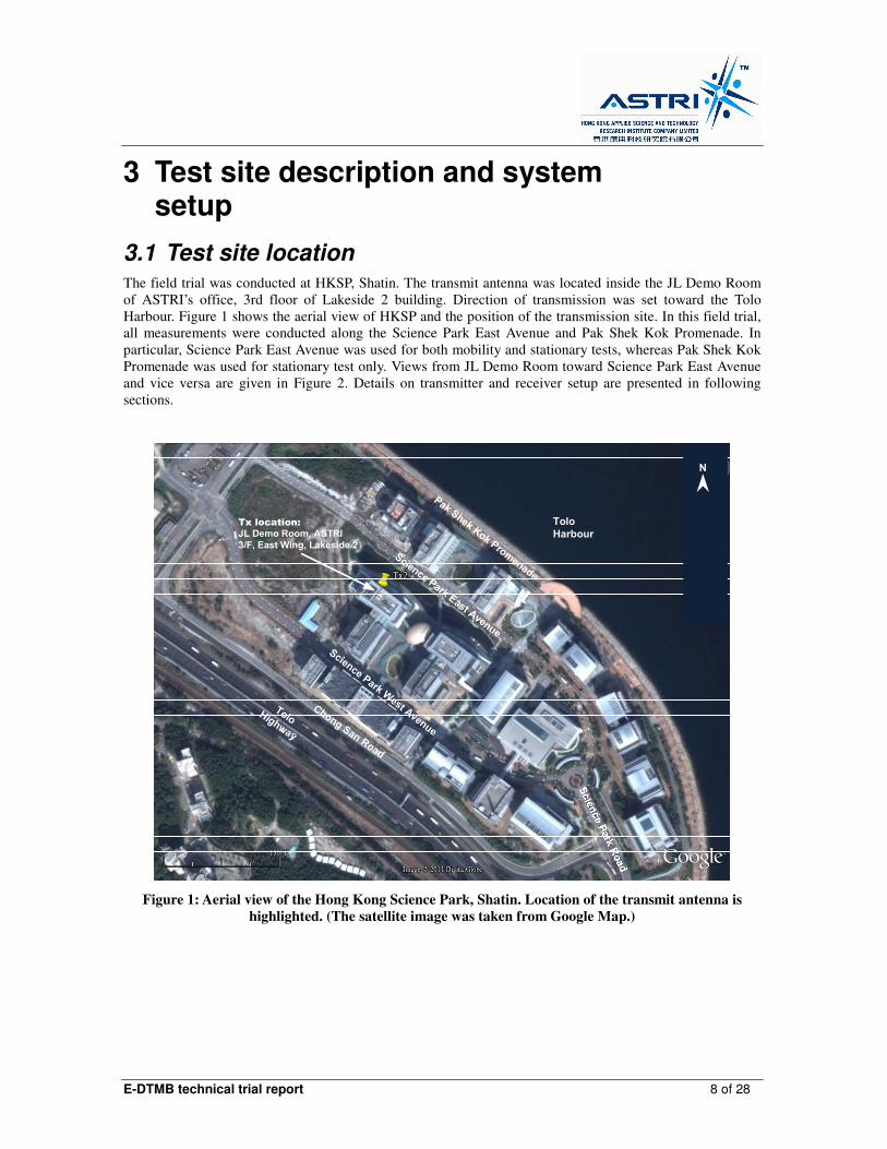
3.1 Test site location The field trial was conducted at HKSP, Shatin. The transmit antenna was located inside the JL Demo Room
of ASTRI’s office, 3rd floor of Lakeside 2 building. Direction of transmission was set toward the Tolo
Harbour. Figure 1 shows the aerial view of HKSP and the position of the transmission site. In this field trial,
all measurements were conducted along the Science Park East Avenue and Pak Shek Kok Promenade. In
particular, Science Park East Avenue was used for both mobility and stationary tests, whereas Pak Shek Kok
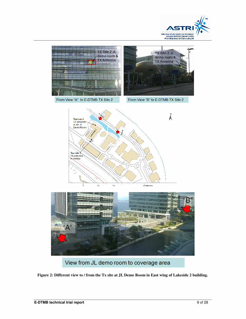
Promenade was used for stationary test only. Views from JL Demo Room toward Science Park East Avenue
and vice versa are given in Figure 2. Details on transmitter and receiver setup are presented in following
sections.
Tolo
Harbour
Pak Shek Kok Promenade
Tolo Highway
Chong San Road
Science Park East Avenue
Science Park West Avenue
Tx location:
JL Demo Room, ASTRI
3/F, East Wing, Lakeside 2
N
Figure 1: Aerial view of the Hong Kong Science Park, Shatin. Location of the transmit antenna is
highlighted. (The satellite image was taken from Google Map.)
E-DTMB technical trial report 9 of 28
Figure 2: Different view to / from the Tx site at JL Demo Room in East wing of Lakeside 2 building.

E-DTMB technical trial report 10 of 28
3.2 Transmission parameters Specification of the transmitter site and E-DTMB transmission parameters for this field trial are summarized
in Table 1 and Table 2.
Table 1: Specification of the transmitter site.
E-DTMB transmitter located at 3/F JL Demo Room,
Lakeside 2, HKSTP
Location (HKGRID) 839740.697 E, 831969.83 N
Antenna mast height ~ 2.4 m above ground level
Room ground level ~ 35 m above sea level
COR of TX antenna ~ 36.7 m
Maximum ERP 0.5W (27 dBm)
TX antenna type 4-dipole panel, 1-face 1-stack
Antenna orientation angle 70º T.N.
Polarization Vertical
Test channel Ch59 (774 - 782 MHz)
Table 2: E-DTMB transmission parameters.
Occupancy-ratio of mobile service
25 %
Carrier mode Multi-carrier
PN header PN 420
Symbol interleaving B = 52, M = 720
Terrestrial mode
QAM / code rate
Payload
64 QAM / 0.6
18.2 Mbps
Mobile mode
QAM / code rate
Payload
4 QAM / 0.4
674 kbps
3.3 Transmitter setup Transmission equipment and the antenna, were installed inside the JL Demo Room of ASTRI office, 3rd
floor, East wing of Lakeside 2 building. The floor plan of JL Demo Room and location of the transmit
antenna are illustrated in Figure 3. The transmit antenna panel was mounted on a purposed built self-stand
steel pole that stood near to the window. The orientation angle of the antenna panel was set to 70o TN. The
antenna panel was not tilted, although it had been designed to have down tilt angle of 20o.
View from entrance to window
Figure 3: Transmitter site - JL Demo Room, ASTRI office.

E-DTMB technical trial report 11 of 28
The equipment list and photographs for the transmitter is given in Table 3 and Figure 4.
Table 3: Equipment list for the transmitter.
Equipment Name Qty
Desktop computer 2
MPEG2 TS player card 2
E-DTMB baseband modulator 1
R&S SFU 1
N male to BNC female adapter 1
Power amplifier 1
Coaxial cable (2 meters) 1
N female to 7-16 Din male adapter 1
RFS UHF antenna panel 1
Transmitter setup. Output of SFU is connected to the power amplifier.
Transmit antenna and power amplifier.
Figure 4: Photograhs of transmission equipment fo the Phase 1a of E-DTMB field trial.
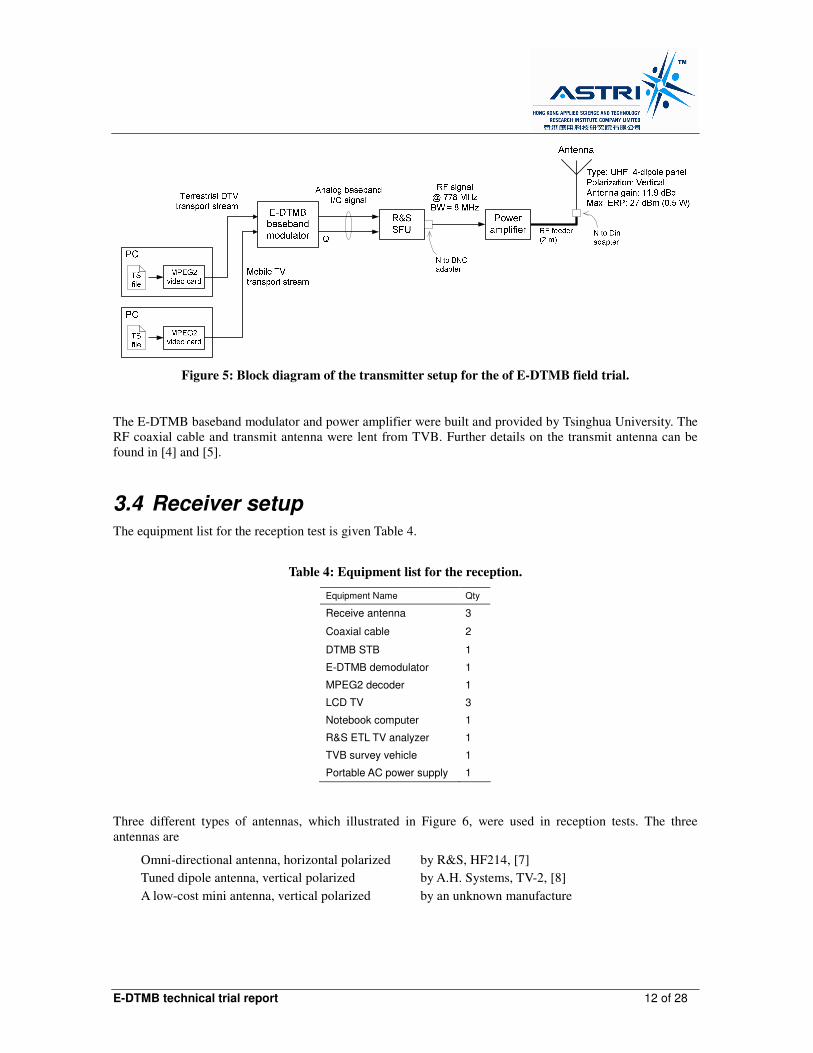
A block diagram of the transmitter for this E-DTMB field trial is shown in Figure 5. The E-DTMB baseband
modulator converted the two independent TS into analog baseband I/Q signal that satisfied the GB2060-2006
standard [1]. The R&S SFU [3] converted the analog baseband I/Q signal into an 8 MHz RF signal centered
at 778 MHz. The power amplifier boosted the power of the RF signal before the signal enter the transmit
antenna and get radiate.
E-DTMB technical trial report 12 of 28
Figure 5: Block diagram of the transmitter setup for the of E-DTMB field trial.
The E-DTMB baseband modulator and power amplifier were built and provided by Tsinghua University. The
RF coaxial cable and transmit antenna were lent from TVB. Further details on the transmit antenna can be
found in [4] and [5].
3.4 Receiver setup The equipment list for the reception test is given Table 4.
Table 4: Equipment list for the reception.
Equipment Name Qty
Receive antenna 3
Coaxial cable 2
DTMB STB 1
E-DTMB demodulator 1
MPEG2 decoder 1
LCD TV 3
Notebook computer 1
R&S ETL TV analyzer 1
TVB survey vehicle 1
Portable AC power supply 1
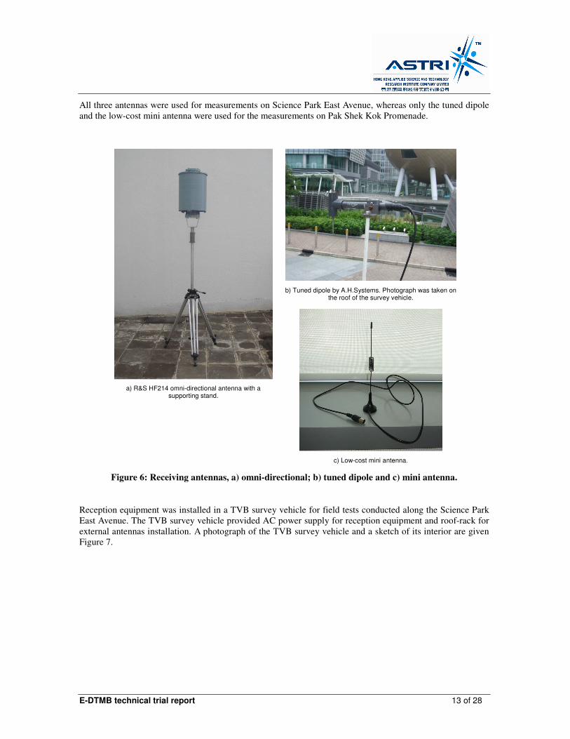
Three different types of antennas, which illustrated in Figure 6, were used in reception tests. The three
antennas are
Omni-directional antenna, horizontal polarized by R&S, HF214, [7]
Tuned dipole antenna, vertical polarized by A.H. Systems, TV-2, [8]
A low-cost mini antenna, vertical polarized by an unknown manufacture
E-DTMB technical trial report 13 of 28
All three antennas were used for measurements on Science Park East Avenue, whereas only the tuned dipole
and the low-cost mini antenna were used for the measurements on Pak Shek Kok Promenade.
b) Tuned dipole by A.H.Systems. Photograph was taken on the roof of the survey vehicle.
a) R&S HF214 omni-directional antenna with a supporting stand.
c) Low-cost mini antenna.
Figure 6: Receiving antennas, a) omni-directional; b) tuned dipole and c) mini antenna.
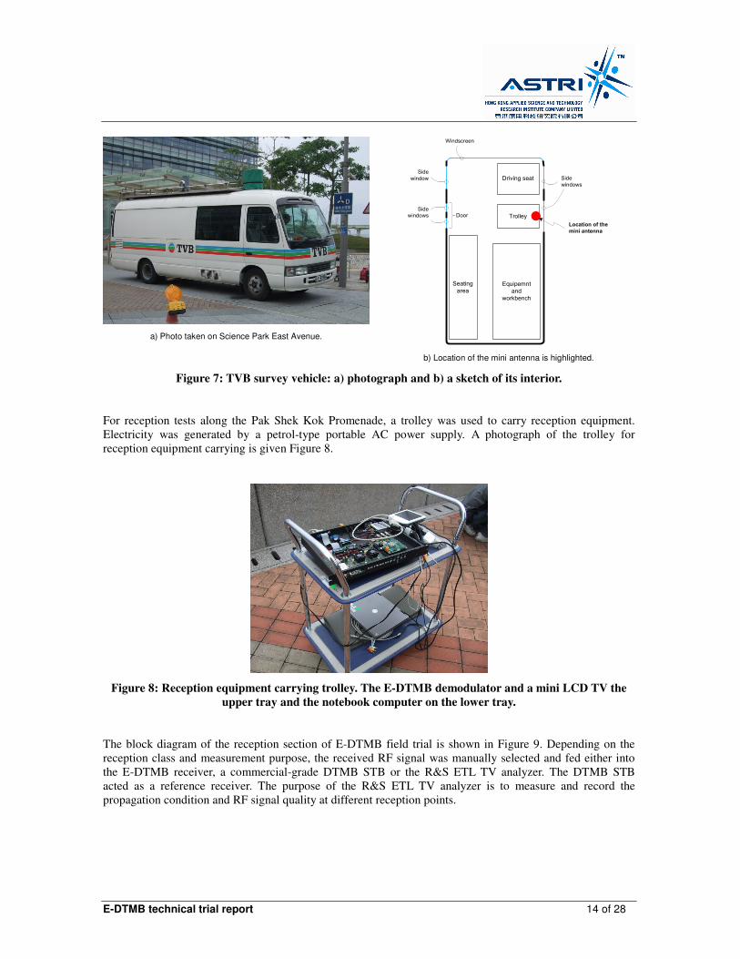
Reception equipment was installed in a TVB survey vehicle for field tests conducted along the Science Park
East Avenue. The TVB survey vehicle provided AC power supply for reception equipment and roof-rack for
external antennas installation. A photograph of the TVB survey vehicle and a sketch of its interior are given
Figure 7.
E-DTMB technical trial report 14 of 28
a) Photo taken on Science Park East Avenue.
Driving seat
Equipemnt
and
workbench
Trolley
Seating
area
Side
windows
Side
window
Windscreen
Side
windows
Location of the
mini antenna
Door
b) Location of the mini antenna is highlighted.
Figure 7: TVB survey vehicle: a) photograph and b) a sketch of its interior.
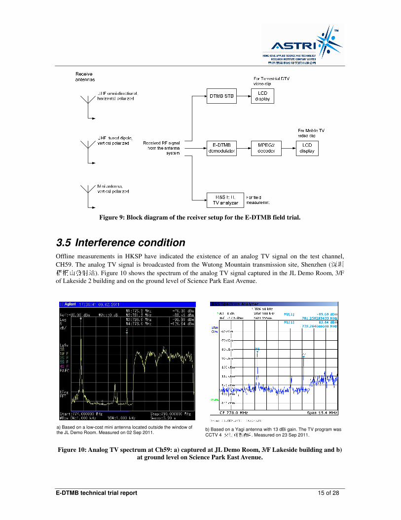
For reception tests along the Pak Shek Kok Promenade, a trolley was used to carry reception equipment.
Electricity was generated by a petrol-type portable AC power supply. A photograph of the trolley for
reception equipment carrying is given Figure 8.
Figure 8: Reception equipment carrying trolley. The E-DTMB demodulator and a mini LCD TV the
upper tray and the notebook computer on the lower tray.
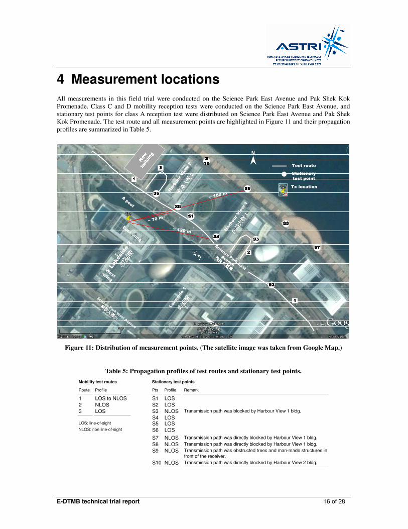
The block diagram of the reception section of E-DTMB field trial is shown in Figure 9. Depending on the
reception class and measurement purpose, the received RF signal was manually selected and fed either into
the E-DTMB receiver, a commercial-grade DTMB STB or the R&S ETL TV analyzer. The DTMB STB
acted as a reference receiver. The purpose of the R&S ETL TV analyzer is to measure and record the
propagation condition and RF signal quality at different reception points.
E-DTMB technical trial report 15 of 28
Figure 9: Block diagram of the rceiver setup for the E-DTMB field trial.
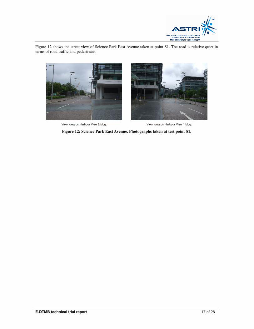
3.5 Interference condition Offline measurements in HKSP have indicated the existence of an analog TV signal on the test channel,
CH59. The analog TV signal is broadcasted from the Wutong Mountain transmission site, Shenzhen (深圳 梧桐山發射站). Figure 10 shows the spectrum of the analog TV signal captured in the JL Demo Room, 3/F
of Lakeside 2 building and on the ground level of Science Park East Avenue.
a) Based on a low-cost mini antenna located outside the window of the JL Demo Room. Measured on 02 Sep 2011.
b) Based on a Yagi antenna with 13 dBi gain. The TV program was
CCTV 4 央視國際頻道. Measured on 23 Sep 2011.
Figure 10: Analog TV spectrum at Ch59: a) captured at JL Demo Room, 3/F Lakeside building and b)
at ground level on Science Park East Avenue.
E-DTMB technical trial report 16 of 28
4 Measurement locations
All measurements in this field trial were conducted on the Science Park East Avenue and Pak Shek Kok
Promenade. Class C and D mobility reception tests were conducted on the Science Park East Avenue, and
stationary test points for class A reception test were distributed on Science Park East Avenue and Pak Shek
Kok Promenade. The test route and all measurement points are highlighted in Figure 11 and their propagation
profiles are summarized in Table 5.
~ 180 m
~ 120 m
~ 70 m
Harbour View 1
Harbour View 2
Science Park East
Avenue
1
2
Lakeside 1
Lakeside 2
A pool
Science Park West Avenue
Test route
Stationary
test point
Tx location
N
East wing
West
wing
Figure 11: Distribution of measurement points. (The satellite image was taken from Google Map.)
Table 5: Propagation profiles of test routes and stationary test points.
Mobility test routes Stationary test points
Route Profile Pts Profile Remark
1 LOS to NLOS S1 LOS
2 NLOS S2 LOS
3 LOS S3 NLOS Transmission path was blocked by Harbour View 1 bldg.
S5 LOS
S6 LOS
S7 NLOS Transmission path was directly blocked by Harbour View 1 bldg.
S8 NLOS Transmission path was directly blocked by Harbour View 1 bldg.
S9 NLOS Transmission path was obstructed trees and man-made structures in
front of the receiver.
S10 NLOS Transmission path was directly blocked by Harbour View 2 bldg.
LOS: line-of-sight
NLOS: non line-of-sight
S4 LOS
E-DTMB technical trial report 17 of 28
Figure 12 shows the street view of Science Park East Avenue taken at point S1. The road is relative quiet in
terms of road traffic and pedestrians.
View towards Harbour View 2 bldg.
View towards Harbour View 1 bldg.
Figure 12: Science Park East Avenue. Photographs taken at test point S1.
E-DTMB technical trial report 18 of 28
5 Measurement results
In this field trial, subjective measure of video quality was used to classify the performance of E-DTMB
signal reception. Video quality was given on a three-level grading:
Good Video clip runs smoothly and clear picture display
Marginal Blocking effect starts to appear but video clip can still run
Fail Video clip freezes or no picture display
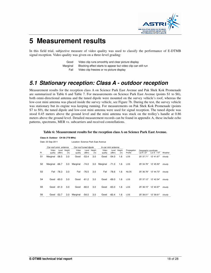
5.1 Stationary reception: Class A - outdoor reception Measurement results for the reception class A on Science Park East Avenue and Pak Shek Kok Promenade
are summarized in Table 6 and Table 7. For measurements on Science Park East Avenue (points S1 to S6),
both omni-directional antenna and the tuned dipole were mounted on the survey vehicle’s roof, whereas the
low-cost mini antenna was placed inside the survey vehicle, see Figure 7b. During the test, the survey vehicle
was stationary but its engine was keeping running. For measurements on Pak Shek Kok Promenade (points
S7 to S9), the tuned dipole and low-cost mini antenna were used for signal reception. The tuned dipole was
stood 0.45 meters above the ground level and the mini antenna was stuck on the trolley’s handle at 0.86
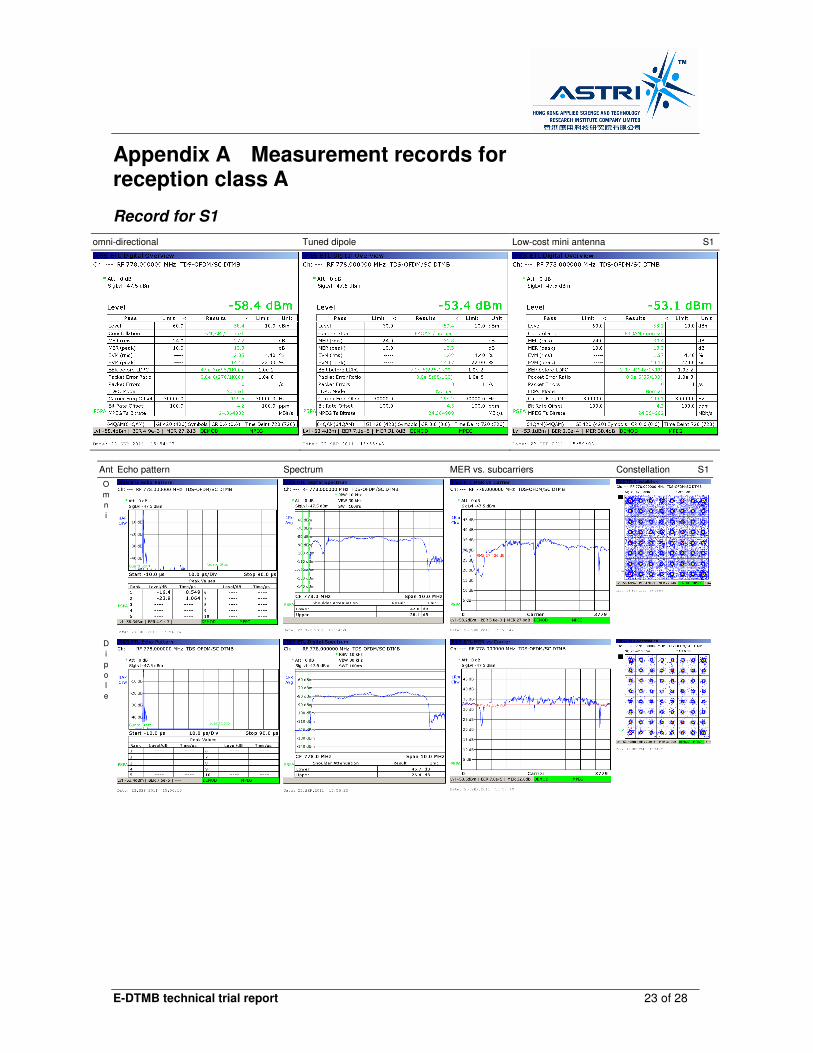
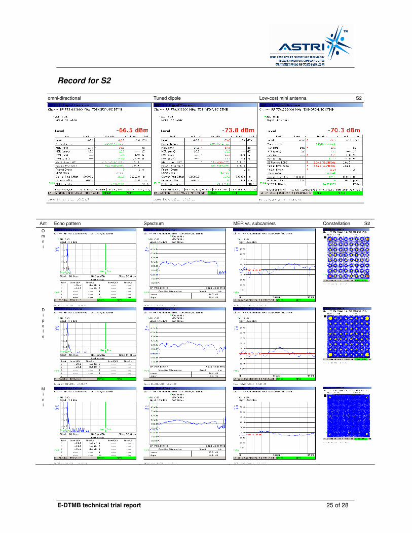
meters above the ground level. Detailed measurement records can be found in appendix A, these include echo
patterns, spectrums, MER vs. subcarriers and received constellations.
Table 6: Measurement results for the reception class A on Science Park East Avenue.
Class A: Outdoor CH 59 (778 MHz)
Date: 23 Sep 2011 Location: Science Park East Avenue
Pt Lat N 22o Lon E 114o
S1 Marginal -58.5 3.0 Good -53.4 3.0 Good -54.0 1.6 LOS 25' 37.71" 12' 41.67" cloudy
S2 Marginal -66.7 3.0 Marginal -74.0 3.0 Marginal -71.0 1.6 LOS 25' 34.76" 12' 45.50" cloudy
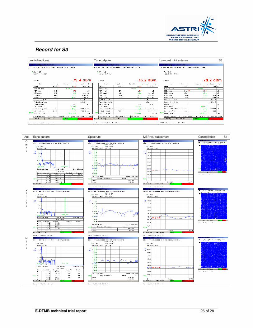
S3 Fail -78.3 3.0 Fail -76.5 3.0 Fail -78.6 1.6 NLOS 25' 36.78" 12' 44.73" cloudy
S4 Good -60.0 3.0 Good -61.2 3.0 Good -69.0 1.6 LOS 25' 37.12" 12' 42.54" cloudy
S5 Good -61.0 3.0 Good -60.0 3.0 Good -63.0 1.6 LOS 25' 38.15" 12' 40.97" cloudy
S6 Good -53.7 3.0 Marginal -54.0 3.0 Good -60.4 1.6 LOS 25' 39.01" 12' 39.61" cloudy
Geographic coordinateVideo
quality
Level
(dBm)
Height
(m)
Video
quality
Level
(dBm)
Height
(m)
Propagation
Profile Weather
Car-roof omni. antenna Car-roof tuned dipole In-car mini antenna
Video
quality
Level
(dBm)
Height
(m)
E-DTMB technical trial report 19 of 28
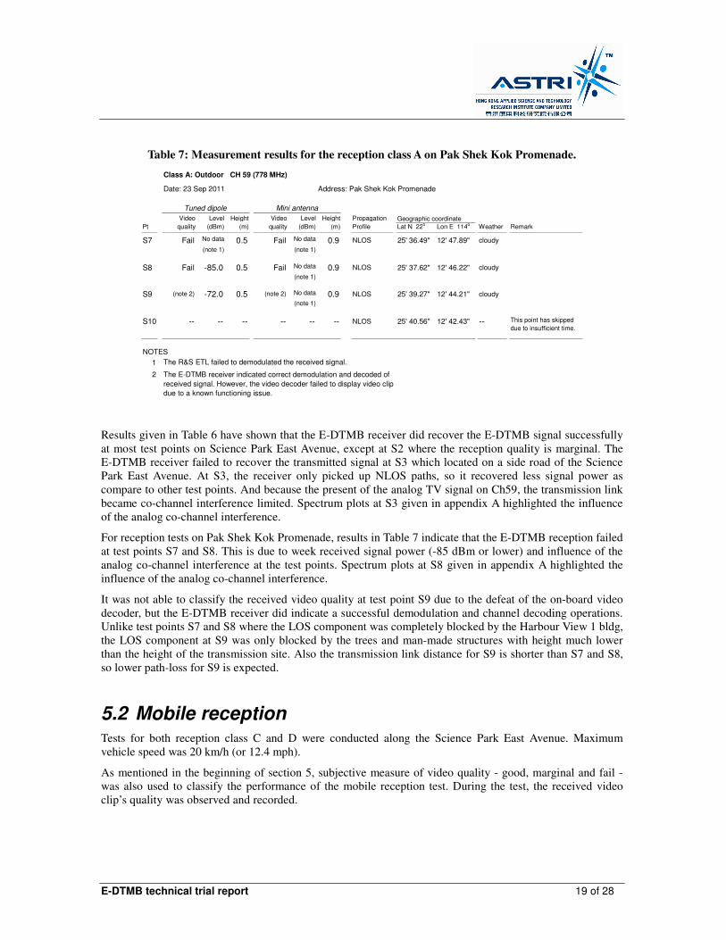
Table 7: Measurement results for the reception class A on Pak Shek Kok Promenade.
Class A: Outdoor CH 59 (778 MHz)
Date: 23 Sep 2011 Address: Pak Shek Kok Promenade
Pt Lat N 22o Lon E 114o Remark
S7 Fail No data 0.5 Fail No data 0.9 NLOS 25' 36.49" 12' 47.89" cloudy
(note 1) (note 1)
S8 Fail -85.0 0.5 Fail No data 0.9 NLOS 25' 37.62" 12' 46.22" cloudy
(note 1)
S9 (note 2) -72.0 0.5 (note 2) No data 0.9 NLOS 25' 39.27" 12' 44.21" cloudy
(note 1)
S10 -- -- -- -- -- -- NLOS 25' 40.56" 12' 42.43" --
NOTES
1
2 The E-DTMB receiver indicated correct demodulation and decoded of
received signal. However, the video decoder failed to display video clip
due to a known functioning issue.
The R&S ETL failed to demodulated the received signal.
This point has skipped
due to insufficient time.
Weather
Height
(m)
Propagation
Profile
Geographic coordinateVideo
quality
Tuned dipole Mini antenna
Level
(dBm)
Height
(m)
Video
quality
Level
(dBm)
Results given in Table 6 have shown that the E-DTMB receiver did recover the E-DTMB signal successfully
at most test points on Science Park East Avenue, except at S2 where the reception quality is marginal. The
E-DTMB receiver failed to recover the transmitted signal at S3 which located on a side road of the Science
Park East Avenue. At S3, the receiver only picked up NLOS paths, so it recovered less signal power as
compare to other test points. And because the present of the analog TV signal on Ch59, the transmission link
became co-channel interference limited. Spectrum plots at S3 given in appendix A highlighted the influence
of the analog co-channel interference.
For reception tests on Pak Shek Kok Promenade, results in Table 7 indicate that the E-DTMB reception failed
at test points S7 and S8. This is due to week received signal power (-85 dBm or lower) and influence of the
analog co-channel interference at the test points. Spectrum plots at S8 given in appendix A highlighted the
influence of the analog co-channel interference.
It was not able to classify the received video quality at test point S9 due to the defeat of the on-board video
decoder, but the E-DTMB receiver did indicate a successful demodulation and channel decoding operations.
Unlike test points S7 and S8 where the LOS component was completely blocked by the Harbour View 1 bldg,
the LOS component at S9 was only blocked by the trees and man-made structures with height much lower
than the height of the transmission site. Also the transmission link distance for S9 is shorter than S7 and S8,
so lower path-loss for S9 is expected.
5.2 Mobile reception Tests for both reception class C and D were conducted along the Science Park East Avenue. Maximum
vehicle speed was 20 km/h (or 12.4 mph).
As mentioned in the beginning of section 5, subjective measure of video quality - good, marginal and fail -
was also used to classify the performance of the mobile reception test. During the test, the received video
clip’s quality was observed and recorded.
E-DTMB technical trial report 20 of 28
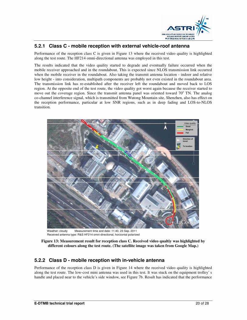
5.2.1 Class C - mobile reception with external vehicle-roof antenna
Performance of the reception class C is given in Figure 13 where the received video quality is highlighted
along the test route. The HF214 omni-directional antenna was employed in this test.
The results indicated that the video quality started to degrade and eventually failure occurred when the
mobile receiver approached and in the roundabout. This is expected since NLOS transmission link occurred
when the mobile receiver in the roundabout. Also taking the transmit antenna location - indoor and relative
low height - into consideration, multipath components are probably not even existed in the roundabout area.
The transmission link has re-established after the receiver left the roundabout and moved back to LOS
region. At the opposite end of the test route, the video quality got worst again because the receiver started to
move out the coverage region. Since the transmit antenna panel was oriented toward 70o TN. The analog
co-channel interference signal, which is transmitted from Wutong Mountain site, Shenzhen, also has effect on
the reception performance, particular at low SNR regions, such as in deep fading and LOS-to-NLOS
transition.
EndStart
Good
Marginal
Fail
Video quality
Direction of
traval
N
Tx location
Weather: cloudy Measurement time and date: 11:40, 23 Sep. 2011
Received antenna type: R&S HF214 omni-directional, horizontal polarized
Figure 13: Measurement result for reception class C. Received video qualtiy was highlighted by
different colours along the test route. (The satellite image was taken from Google Map.)
5.2.2 Class D - mobile reception with in-vehicle antenna
Performance of the reception class D is given in Figure 14 where the received video quality is highlighted
along the test route. The low-cost mini antenna was used in this test. It was stuck on the equipment trolley’ s
handle and placed near to the vehicle’s side window, see Figure 7b. Result has indicated that the performance
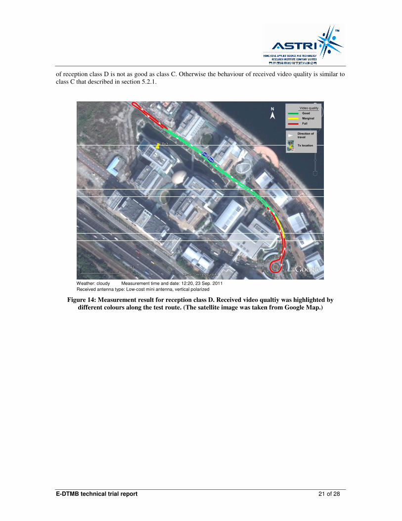
E-DTMB technical trial report 21 of 28
of reception class D is not as good as class C. Otherwise the behaviour of received video quality is similar to
class C that described in section 5.2.1.
Good
Marginal
Fail
Video quality
Direction of
traval
Tx location
EndStart
N
Weather: cloudy Measurement time and date: 12:20, 23 Sep. 2011
Received antenna type: Low-cost mini antenna, vertical polarized
Figure 14: Measurement result for reception class D. Received video qualtiy was highlighted by
different colours along the test route. (The satellite image was taken from Google Map.)
E-DTMB technical trial report 22 of 28
6 Discussion
Field results presented in this document demonstrate the successful integration and operation of the setup of
E-DTMB system at ASTRI in HKSP. Measurements obtained from outdoor stationary and mobility tests
indicate good reception under LOS propagation conditions but reception failure under NLOS conditions that
caused by buildings. By taking the consideration of current location of the transmission site - indoor and
below building rooftop - one should not conclude that the E-DTMB system is not capable of NLOS
transmissions.
E-DTMB technical trial report 23 of 28
Appendix A Measurement records for reception class A
Record for S1
omni-directional Tuned dipole Low-cost mini antenna S1
Ant Echo pattern Spectrum MER vs. subcarriers Constellation S1
O
m
n
i
D
i
p
o
l
e
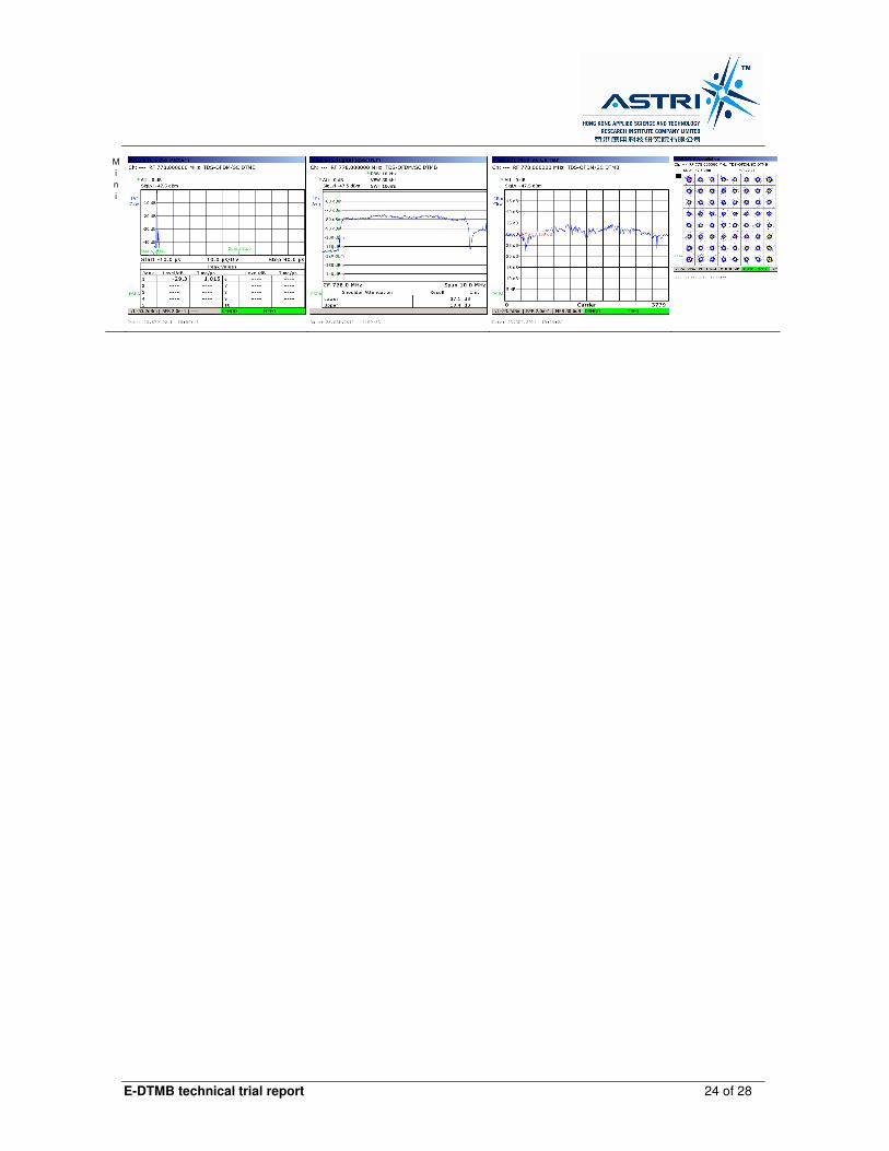
E-DTMB technical trial report 24 of 28
M
i
n
i
E-DTMB technical trial report 25 of 28
Record for S2
omni-directional Tuned dipole Low-cost mini antenna S2
Ant Echo pattern Spectrum MER vs. subcarriers Constellation S2
O
m
n
i
D
i
p
o
l
e
M
i
n
i
E-DTMB technical trial report 26 of 28
Record for S3
omni-directional Tuned dipole Low-cost mini antenna S3
Ant Echo pattern Spectrum MER vs. subcarriers Constellation S3
O
m
n
i
D
i
p
o
l
e
M
i
n
i

E-DTMB technical trial report 27 of 28
Record for S7
No measurement data were recorded by the R&S ETL because signal level was too low.
Record for S8
Tuned dipole Low-cost mini antenna S8
No measurement data
Ant Echo pattern Spectrum MER vs. subcarriers Constellation S8
D
i
p
o
l
e
No cancellation points displayed
M
i
n
i
No measurement recorded No measurement recorded No measurement recorded No measurement recorded

E-DTMB technical trial report 28 of 28
Record for S9
Tuned dipole Low-cost mini antenna S9
No measurement recorded
Ant Echo pattern Spectrum MER vs. subcarriers Constellation S9
D
i
p
o
l
e
M
i
n
i
No measurement recorded No measurement recorded No measurement recorded No measurement recorded