Embed Size (px)
Citation preview

Report onAcid Sulphate Soil Management Plan
Proposed Train Support FacilityWoodlands Close, Hexham
Prepared for QR National
Project 39798.08November 2012


Acid Sulphate Soil Management Plan, Proposed Train Support Facility Project 39798.08Woodlands Close, Hexham November 2012
Table of Contents
Page
1. Introduction ................................................................................................................... 1
2. Site Description and Regional Geology ......................................................................... 1
3. Proposed Development ................................................................................................ 2
4. Summary of Acid Sulphate Soil and Site Conditions ..................................................... 4
5. Potential For Oxidising Acid Sulphate Soils .................................................................. 8
6. Management Strategy................................................................................................... 9
6.1 Soil Treatment ..................................................................................................... 9
6.2 Neutralising Leachate ........................................................................................ 10
6.3 Dewatering ........................................................................................................ 11
7. Monitoring Strategies .................................................................................................. 12
7.1 Procedures ........................................................................................................ 12
7.2 Acceptance Criteria ........................................................................................... 13
8. Contingency Plan ........................................................................................................ 14
9. References ................................................................................................................. 15
10. Limitations .................................................................................................................. 15
Appendix A: About this Report
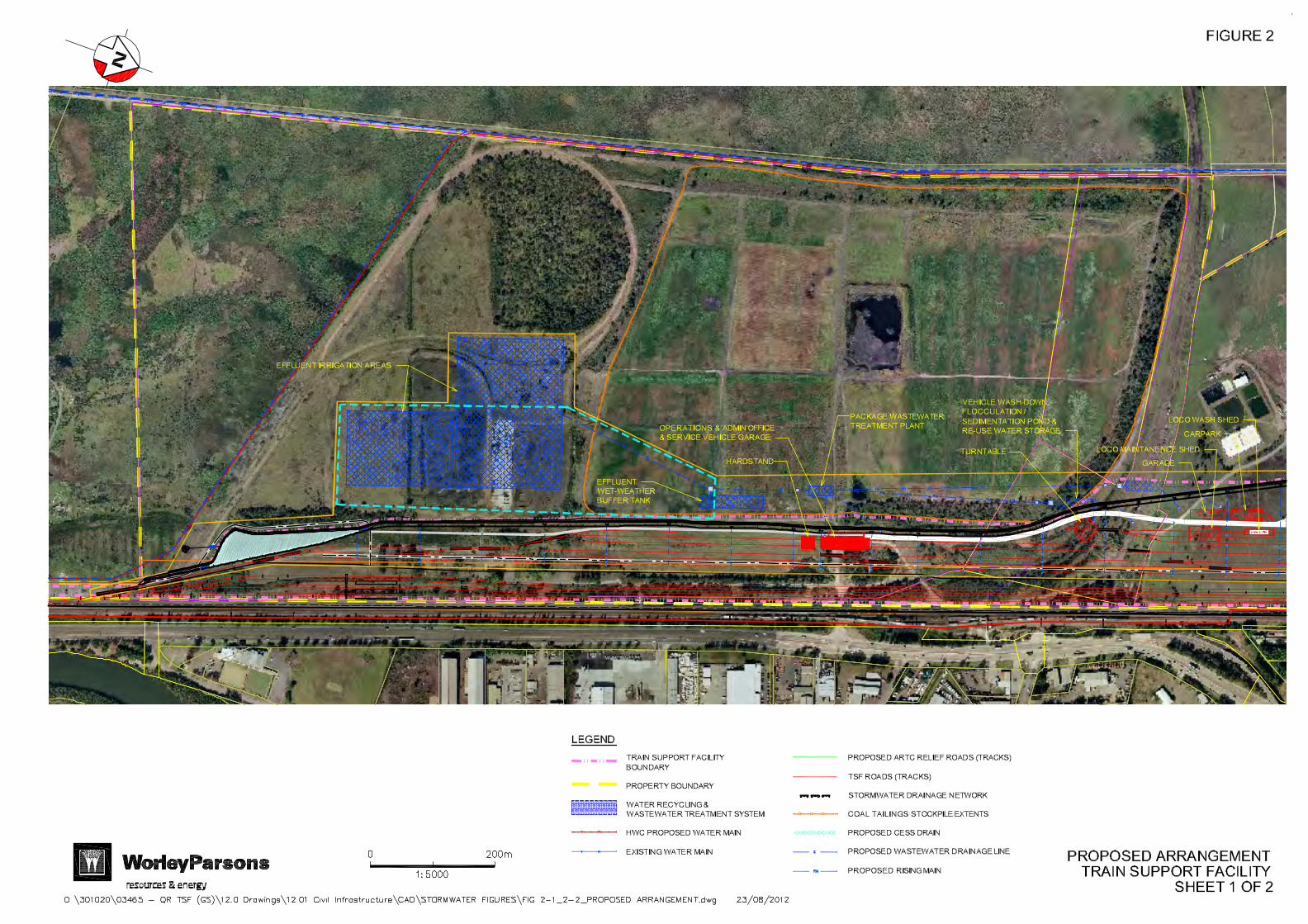
Figure 2 – Proposed Arrangement – Train Support Facility (WorleyParsons)
(Sheet 1 of 2 and Sheet 2 of 2)
Figure C0002 – Areas of Disturbance – Cut (GHD – 2216395-16-FIG-C0002) – Rev 4 – 10 October 2012
Figure C0003 – Areas of Disturbance – Fill (GHD – 2216395-16-FIG-C0003) – Rev 2 – 26 September 2012
Drawing 1-2 – Test Location Plan (Ref 1)

1 of 15
Acid Sulphate Soil Management Plan, Proposed Train Support Facility Project 39798.08Woodlands Close, Hexham November 2012
Report on Acid Sulphate Soil Management Plan
Proposed Train Support Facility
Woodlands Close, Hexham
1. Introduction
This Acid Sulphate Soil Management Plan (ASSMP) has been prepared for the proposed Train Support Facility (TSF) at Hexham, New South Wales. The work was carried out at the request of QR National and in consultation with ADW Johnson Pty Limited. This report supersedes Douglas Partners Pty Ltd (DP) previous ASSMP issued in May 2012 (Project 39798.08). The proposed TSF development is presented in Section 3 of this report. Development of the TSF will result in disturbance of underlying acid sulphate soils through localised excavation and dewatering during construction. The ASSMP was prepared to provide the following information:
• Acid sulphate soil management strategies for the proposed TSF development;
• Monitoring program for soil and water quality;
• Contingency procedure. The results of the previous geotechnical investigation undertaken at the site (Ref 1) has been used in formulating this Acid Sulphate Soil Management Plan (ASSMP). It is noted that this investigation was limited to the eastern portion of the site and as such this ASSMP should be considered generic. Reference has also been made to the NSW Acid Sulphate Soil Management Advisory Committee (ASSMAC), August 1998 (Ref 2), and recent experience with similar works in acid sulphate soils. 2. Site Description and Regional Geology
The site is located on the western side of the New England Highway and Pacific Highway at Hexham, NSW. The site comprises an irregular shaped area of approximately 255 ha and is bounded to the east by the Great Northern Railway, to the north by Woodland Close and New England Highway, to the west generally by Chichester pipeline and to the south by private rural residential property. The proposed TSF development area is generally limited to a corridor about 150 m wide adjacent to the Great Northern Railway, due to the linear nature of the development. The ARTC Hexham Relief Roads Project which comprised five new train line (tracks) is located between the proposed TSF and the Great Northern Railway. The development generally only occupies a relatively narrow strip along the eastern side of the overall site, as shown on the WorleyParsons general arrangement figures in Appendix A.

2 of 15
Acid Sulphate Soil Management Plan, Proposed Train Support Facility Project 39798.08Woodlands Close, Hexham November 2012
It is noted that the previous preliminary geotechnical investigation (Ref 1) was limited to the proposed development area on the eastern portion of the site generally parallel with the Great Northern Railway. This ASSMP is therefore based on data collected from a limited portion of the site. The 1:100,000 scale Newcastle Coalfield Regional Geology map (Sheet 9321), published by the Department of Mineral Resources, indicates that the site is underlain by Quaternary Alluvium. The alluvium typically comprises unconsolidated sediments deposited in a fluvial or estuarine environment, and includes gravel, sand, silt and clay. Reference to the 1:25,000 scale Acid Sulphate Soil Risk Map for Beresfield (Sheet 9232 N3), published by the Department of Land and Water Conservation, indicates that the entire site has a high probability of acid sulphate soils within one metre of the (natural) ground surface. While the geotechnical investigation was limited to the eastern portion of the site, reference to the regional geology and acid sulphate soil risk maps suggest natural subsurface conditions are likely to be similar within the development area. 3. Proposed Development
It is understood that the proposed development includes the construction of a rolling stock maintenance facility, located adjacent to the Great Northern Railway Line. The proposed development will include the following aspects: Stage 1:
• Construction of a connection to the Tarro Interchange and main vehicle access road to the site;
• Construction of earthworks, drainage, circulating roadwork and the construction of one provisioning track, a train examination road, two cut out roads and two wagon maintenance roads;
• Filling and grading of the TSF area (approximately 380,000 m³ of suitable fill to be imported) so that site levels can match the adjoining rail network;
• Associated signalling and connections to the down coal road on the Great Northern Line;
• Construction of a Provisioning Facility;
• 2 x Provisioning roads and UTM road;
• 2 x Wagon Maintenance roads;
• Wagon storage road;
• Construction of a Wagon Maintenance Building;
• 1 x Wagon storage road;
• Fuel storage area to initially accommodate 2 x 100,000 litre tanks and to be constructed in such a manner as to allow for future expansion of up to 4 x 100,000 litre tanks of diesel fuel.
3 of 15
Acid Sulphate Soil Management Plan, Proposed Train Support Facility Project 39798.08Woodlands Close, Hexham November 2012
Stage 2:
• Locomotive Maintenance Building;
• Locomotive Wash Building;
• Locomotive Turntable;
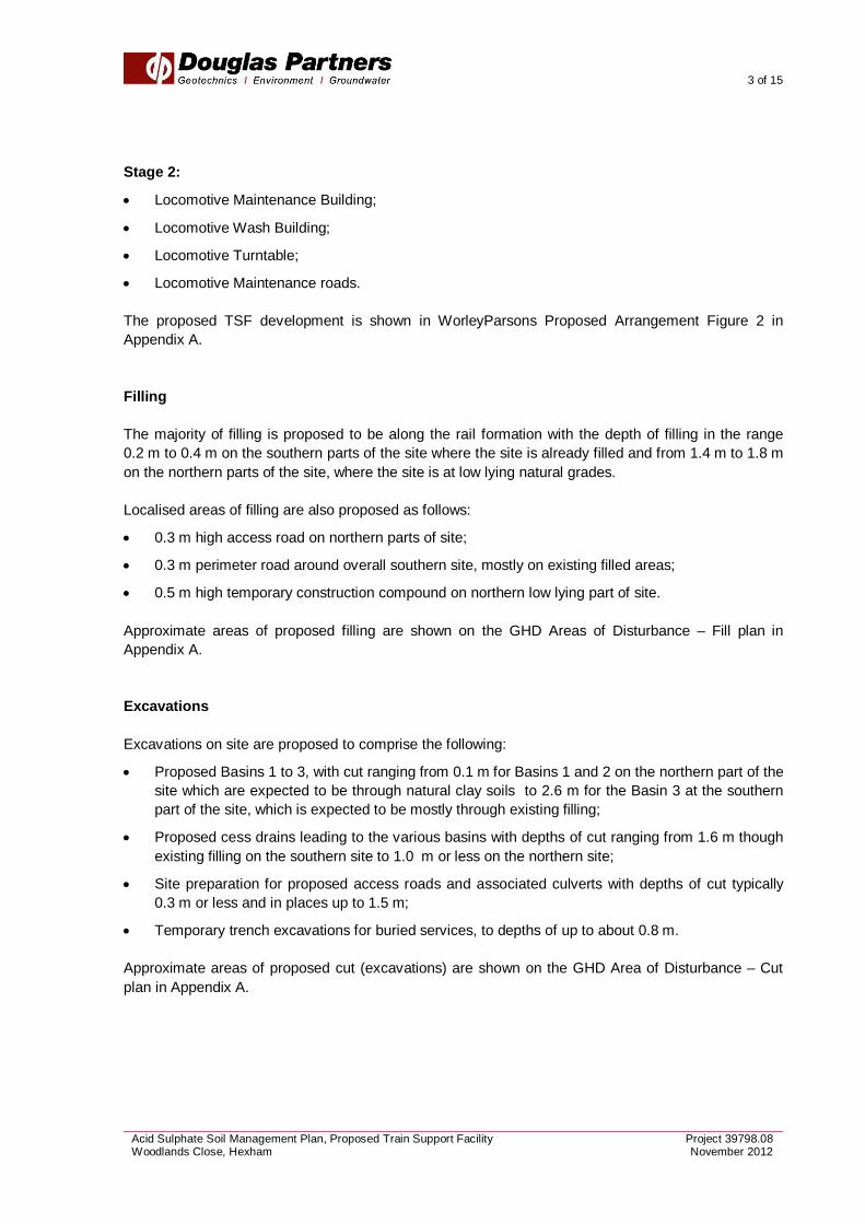
• Locomotive Maintenance roads. The proposed TSF development is shown in WorleyParsons Proposed Arrangement Figure 2 in Appendix A. Filling The majority of filling is proposed to be along the rail formation with the depth of filling in the range 0.2 m to 0.4 m on the southern parts of the site where the site is already filled and from 1.4 m to 1.8 m on the northern parts of the site, where the site is at low lying natural grades. Localised areas of filling are also proposed as follows:
• 0.3 m high access road on northern parts of site;
• 0.3 m perimeter road around overall southern site, mostly on existing filled areas;
• 0.5 m high temporary construction compound on northern low lying part of site. Approximate areas of proposed filling are shown on the GHD Areas of Disturbance – Fill plan in Appendix A. Excavations Excavations on site are proposed to comprise the following:
• Proposed Basins 1 to 3, with cut ranging from 0.1 m for Basins 1 and 2 on the northern part of the site which are expected to be through natural clay soils to 2.6 m for the Basin 3 at the southern part of the site, which is expected to be mostly through existing filling;
• Proposed cess drains leading to the various basins with depths of cut ranging from 1.6 m though existing filling on the southern site to 1.0 m or less on the northern site;
• Site preparation for proposed access roads and associated culverts with depths of cut typically 0.3 m or less and in places up to 1.5 m;
• Temporary trench excavations for buried services, to depths of up to about 0.8 m. Approximate areas of proposed cut (excavations) are shown on the GHD Area of Disturbance – Cut plan in Appendix A.

4 of 15
Acid Sulphate Soil Management Plan, Proposed Train Support Facility Project 39798.08Woodlands Close, Hexham November 2012
4. Summary of Acid Sulphate Soil and Site Conditions
Previous testing (Ref 1) involved acid sulphate soil screening tests within the DP laboratory and detailed acid sulphate soil testing on selected samples by ALS Environmental Pty Ltd (ALS). The acid sulphate screening results have been reproduced in Table 1, below. The results of the acid sulphate soil assessment generally indicated the presence of potential acid sulphate soil (PASS) conditions within natural soils.

5 of 15
Acid Sulphate Soil Management Plan, Proposed Train Support Facility Project 39798.08Woodlands Close, Hexham November 2012
Table 1: Acid Sulphate Soil Screening Tests
Bore / Test Pit
Sample Depth a
(m)
Sample RL
(m AHD) Sample Description
Screening Test Results
pH Strength of
Reaction b pHF pHFOX pHF - pHFOX
14 2.4 -0.9 Silty Sand – grey 7.2 2.6 4.6 3FH
14 2.9 -1.4 Silty Sand – grey 7.4 5.2 2.2 1
16 2.3 0.0 Silty Clay – grey / brown 7.3 6.1 1.2 1-2
16 2.8 -0.5 Sandy Silty Clay – grey 7.6 6.5 1.1 1
16 3.0-3.45 -0.7 to -1.1 Sandy Silty Clay – grey 7.6 2.3 5.3 1-2
21 0.5-0.95 0.6 to 1.0 Silty Clay – grey brown 7.4 6.2 1.2 1-2
21 1.5-1.95 0.0 to -0.4 Silty Clay – grey brown 7.6 6.9 0.7 1
21 2.4 -0.9 Sandy Silt – grey 7.5 6.9 0.6 1
21 3.0-3.45 -1.5 to -1.9 Clayey Sand – grey 7.6 6.2 1.4 1
22 0.4 0.3 Silty Clay – grey 6.8 5.9 0.9 1H
22 0.9 -0.2 Silty Clay – grey 6.8 6.7 0.1 1H
22 1.4 -0.7 Clayey Silty Sand – grey mottled orange
7.0 6.8 0.2 1
22 1.7 -1.0 Clayey Silty Sand – grey mottled orange
7.1 6.9 0.2 1
22 2.4 -1.7 Clayey Silty Sand – grey mottled orange
7.1 6.9 0.2 1
23 0.7 0.4 Silty Clay – grey 7.4 6.6 0.8 1H
23 0.9 0.2 Silty Clay – grey 7.2 6.6 0.6 1H
23 1.2 -0.1 Clayey Silty Sand – grey 7.1 7.0 0.1 1H
24 0.4 3.1 Silty Clay – grey brown 7.3 6.0 1.3 1
24 0.7 2.8 Silty Sand – grey 6.7 6.3 0.4 1
24 0.9 2.6 Silty Sand – grey 6.7 6.2 0.5 1
24 1.6 1.8 Silty Sand – grey 6.5 5.5 1.0 1
25 0.8-0.95 0.4 to 0.5 Silty Sand - grey 8.4 7.2 1.2 1
25 1.4 -0.1 Silty Sand - brown 8.0 7.5 0.5 1
25 1.5-1.95 -0.2 to -0.6 Silty Sand - brown 8.0 6.4 1.6 1
25 2.4 -1.1 Silty Sand – brown (shells) 8.5 6.9 1.6 1-2
25 3.9 -2.6 Silty Sand - brown 8.3 6.3 2.0 1-2
27 1.5-1.95 0.3 to -0.2 Silty Clay - grey 8.1 5.5 2.6 1
27 2.4 -0.6 Clayey Silty Sand - grey 8.1 6.3 1.7 1
27 2.9 -1.1 Clayey Silty Sand - grey 8.0 6.0 2.0 1-2
27 3.0-3.45 -1.2 to -1.7 Clayey Silty Sand - grey 8.2 7.2 1.0 1-2
28 3.3 -0.3 Silty Clay - grey 7.8 3.9 3.9 1-2
28 4.5-4.95 -1.5 to -1.9 Sandy Silt - grey 7.6 5.6 2.0 1-2

6 of 15
Acid Sulphate Soil Management Plan, Proposed Train Support Facility Project 39798.08Woodlands Close, Hexham November 2012
Table 1: Acid Sulphate Soil Screening Tests (continued)
Bore / Test Pit
Sample Depth a
(m)
Sample RL
(m AHD) Sample Description
Screening Test Results
pH Strength of
Reaction b pHF pHFOX pHF - pHFOX
30 0.4 1.4 Sandy Clay - brown 5.9 4.4 1.5 2
30 0.5-0.95 0.8 to 1.3 Sandy Clay - brown 6.3 6.3 0.0 1-2
30 1.4 0.4 Clay - grey 7.2 6.6 0.6 1-2
30 1.5-1.95 0.3 to -0.2 Clay - grey 7.1 6.5 0.6 1
30 2.4 -0.6 Silty Sand – grey mottled orange 7.0 6.6 0.4 1
30 3.0-3.45 -1.2 to -1.7 Clayey Silt – grey (shells) 7.7 2.4 5.3 1-2
30 4.5-4.95 -2.7 to -3.2 Clayey Silt – grey (shells) 7.5 2.6 4.9 4HF
31 1.3 0.0 Silty Clay – grey mottled orange 7.4 6.1 1.3 1H
31 1.5 -0.2 Silty Clay – grey mottled orange 7.0 6.9 0.1 1H
31 1.8 -0.5 Silty Clay – grey mottled orange 7.7 7.6 0.1 1H
34 1.3 -0.7 Silty Clay - grey 7.2 6.4 0.8 1
34 1.4-1.95 -0.8 to -1.35 Silty Clay - grey 7.1 6.5 0.6 1
34 2.4 -1.8 Silty Clay - grey 7.0 6.1 0.9 1
34 3.0-3.45 -2.4 to -2.8 Silty Clay - grey 7.2 4.5 2.7 1
36 0.4 0.8 Silty Sand - brown 6.9 5.4 1.5 1-2
36 0.5-0.95 0.3 to 0.7 Sandy Clay - brown 7.6 7.6 0.0 1
36 1.4 -0.2 Sand - brown 8.0 7.8 0.2 1
36 1.5-1.95 -0.3 to -0.7 Sand - brown 8.1 7.8 0.3 1
36 2.5 -1.3 Silty Sand - grey 8.1 6.6 1.5 1
36 3.0-3.45 -1.8 to -2.2 Silty Sand - grey 8.1 4.8 3.3 1-2
36 4.0 -2.8 Silty Sand - grey 8.2 6.8 1.4 1-2
37 1.4 -0.1 Clay - grey 7.3 5.2 2.1 1
37 2.4 -1.1 Clayey Silt - grey 7.3 2.9 4.4 1
Guideline
Sands to Loamy Sands
<4c <3.5d >1d - Sandy Loams to Light Clays
Medium to Heavy Clays and Silty Clays
Notes to Table 1:
a Depth below ground surface
b Strength of Reaction
1 denotes no or slight reaction
2 denotes moderate reaction
3 denotes high reaction
4 denotes very vigorous reaction
F denotes bubbling/frothy reaction indicative of organics
H denotes heat generated
c For actual Acid Sulphate soils (ASS)
d Indicative value only for Potential Acid Sulphate Soils (PASS) Shaded results indicate potential for acid generation upon oxidation (ie PASS)

7 of 15
Acid Sulphate Soil Management Plan, Proposed Train Support Facility Project 39798.08Woodlands Close, Hexham November 2012
Detailed laboratory testing for TPA, TAA and Chromium Reducible Sulphur content was undertaken on five selected soil samples and results are presented in Table 2 below. Table 2: Detailed Acid Sulphate Soil Laboratory Testing
Bore / Test Pit
Sample Depth a
(m)
Sample RL
(m AHD) Sample Description
Laboratory Results
pHKCLScr %S
TAA (mole H+/t)
TPA (mole H+/t)
14 2.4 -0.9 Silty Sand - grey 5.6 0.65 6 359
16 3.0-3.45 -0.7 to -1.1 Sandy Silty Clay - grey 6.8 0.08 <2 388
27 1.5-1.95 0.3 to -0.2 Silty Clay - grey 5.5 <0.02 21 184
28 3.3 -0.3 Silty Clay - grey 5.9 <0.02 4 <2
30 0.4 1.4 Sandy Clay - brown 5.4 0.04 16 230
Guideline
Sands to Loamy Sands
-
0.03 18 18
Sandy Loams to Light Clays 0.06b/0.03c 36b/18c 36b/18c
Medium to Heavy Cays and Silty
Clays 0.1b/0.03c 62b/18c 62b/18c
Notes to Table 2:
a Depth below ground surface
b ASSMAC Action Criteria for disturbance of 1-1000 tonnes of material
c ASSMAC Action Criteria for disturbance of more than 1000 tonnes of material
Shaded results indicate an exceedence of ASSMAC action criteria for 1-1000 tonnes of ASS soil (Ref 2)
The result of the chromium reducible sulphur testing and TPA testing for samples 14/2.4 m, 16/3.0-3.45 m, 27/1.5-1.95 m and 30/0.4 m exceed the ASSMAC action criteria (Ref 2) for excavations above and below 1000 tonnes. The results of detailed laboratory analysis therefore confirm that potential acid sulphate soils are present within the site. For construction purposes, disturbance of soils (either by excavation or dewatering) within natural soils (ie excluding filling) should be treated as potential acid sulphate soils and managed under the guidance of this ASSMP. The preliminary geotechnical investigation (Ref 1) found subsurface conditions generally comprised filling (typically coarse coal reject and intermixed sand and clays) up to 2 m depth in the southern portion of the investigation area, overlying alluvial clays, overlying sands, overlying residual clays at depth. Groundwater levels typically varied from the ground surface to about 2 m below ground level. Due to frequent irrigation over the northern portion of the site, combined with flooding, perched water levels within fill and the ground surface may have been present. The preliminary contamination assessment (PCA) conducted at the site by DP (Ref 4) included drilling/ excavation of a series of bores / pits across the site. Subsurface conditions encountered were similar to those identified in Reference 1, with the exception of deeper fill within Lot 311, DP583724 and Lot 1, DP155530.

8 of 15
Acid Sulphate Soil Management Plan, Proposed Train Support Facility Project 39798.08Woodlands Close, Hexham November 2012
Groundwater levels measured during the PCA varied between about 0.3 m to 2.6 m below ground level (RL 0.2 AHD to 2.9 AHD). It should be noted that groundwater levels are affected by factors such as climatic conditions and soil permeability and will therefore vary with time. Details of the acid sulphate soil assessment undertaken, along with copies of borehole logs are found in Reference 1. Drawing 1-2, attached shows the test locations from Reference 1. The PCA indicated the presence of localised soil contamination generally within fill materials. The presence of widespread soil contamination in site filling and natural underlying soils within the TSF development area was considered to be low. Remediation of localised contaminated soils was recommended in the PCA. Such remediation should be conducted in accordance with site specific Remediation Action Plan (RAP). Wide spread surface water and groundwater impacts have been identified both on-site and immediately off-site (i.e. generally E.Coli, nutrients, metals). Earthworks including excavation and dewatering should be conducted with due regard to the presence of localised soil contamination, surface water and groundwater impacts, and acid sulphate soils. 5. Potential For Oxidising Acid Sulphate Soils
The following activities may expose acid sulphate soils to oxidising conditions during construction:
• Any excavation (i.e. for underground services, bulk earthworks, stripping of topsoils etc) within PASS;
• Installation of piles (if any) within PASS where spoil is generated;
• Dewatering of excavations during the construction works.
Excavations associated with the construction of the TSF are expected to include:
• Proposed Basins 1 to 3;
• Proposed cess drains;
• Site preparation for proposed access roads and associated culverts;
• Temporary trench excavations for buried services. Based on the shallow groundwater levels at site it is anticipated that most excavations will intersect groundwater. Temporary dewatering may be required to allow construction activities, especially for the access road, culvert and buried service excavations. For the proposed cess drains and detention ponds it may be possible to excavate these without dewatering. Excavations on the southern parts of the site will be predominantly through existing filling which is typically granular and can be expected to be relatively permeable. Dewatering is likely to be achieved by a combination of sump and pump methods for localised excavations with the possibility of spear point dewatering in some areas.

9 of 15
Acid Sulphate Soil Management Plan, Proposed Train Support Facility Project 39798.08Woodlands Close, Hexham November 2012
On the northern parts of the site excavations will be through the natural clay soils, which are generally of low permeability with the exception of local sandy or silty layers. Sump and pump dewatering is expected to be used and due to the low permeability of these soils flow rates are expected to be relatively low if they are not under surface water. 6. Management Strategy
6.1 Soil Treatment
Neutralisation of PASS should be undertaken in accordance with the ASSMAC guidelines, as discussed below. The excavated PASS material should be contained within a suitable bunded area with an impermeable base and appropriately neutralised prior to backfilling. The location of the bunded area should be selected in order to minimise the potential for impact on nearby sensitive receptors. Any leachate produced in the bunded area should be contained for monitoring and treatment as discussed below. Suitable neutralising agents for acid sulphate or potential acid sulphate soils include agricultural lime (CaCO3), calcined magnesia (MgO or Mg(OH)2), and dolomite (MgCO3.CaCO3). An assessment of the dosing rate for lime treatment can be calculated from the results of detailed laboratory testing, using the following equation, which includes a factor of safety: Alkali Material Required (kg)
per unit volume of soil (m3) = FOSxDx ENV(%)
100 x
19.98
623.7 x S % ⎟
⎠⎞
⎜⎝⎛
where: %S = net acidity (% S units); 623.7 = % S to mol H+/t;
19.98 = mol H+/t to kg CaCO3 /t;
D = Bulk density of soil (t/m3);
FOS = Factor of safety (usually 1.5);
ENV = Effective Neutralising Value (e.g. 80% for Grade 1 Agricultural lime).
Note: The ENV is calculated based on the molecular weight, particle size and purity of the neutralising agent and should be assessed for proposed materials in accordance with ASSMAC (Ref 2). It is recommended that Grade 1 agricultural lime is used for the neutralisation of potential acid sulphate soils excavated during the construction.

10 of 15
Acid Sulphate Soil Management Plan, Proposed Train Support Facility Project 39798.08Woodlands Close, Hexham November 2012
The following liming/monitoring procedures for the treatment of PASS are recommended:
• All excavated soil should be contained within a suitably bunded area and kept moist to minimise oxidation, prior to treatment and neutralisation with lime. Progressive neutralisation will minimise the area required for bunding;
• The base of the excavation should be treated with approximately 1 kg/m2 of agricultural lime;
• Stockpiled soil should be limed at an average rate of about 37 kg/m3 of soil (27 kg lime/tonne of soil) for neutralisation as soon as practicable following excavation. Lime treatment rates based on the detailed laboratory testing undertaken in Reference 1 ranged from 24 kg/m3 of soil to 52 kg/m3 of soil. The average value should be used initially and refined based on monitoring results as construction proceeds;
• The neutralising agent and acid sulphate soils should be thoroughly mixed and aerated using, for example, an agricultural lime spreader and excavator. The soil should be treated in layers up to 300 mm thick to encourage aeration (ie incorporate treatment with progressive reuse of soil or disposal at a suitably licensed landfill);
• It should be noted that the actual lime rate required will also depend on the results of monitoring during neutralisation. Additional lime will be required if monitoring results indicate that appropriate neutralisation has not been achieved. Conversely the liming rate may decrease if monitoring suggests over-liming is occurring;
• Sampling and testing should be undertaken in accordance with Section 6.1 to verify the neutralisation treatment. The acceptance criteria are discussed in Section 6.2. Depending on the results of testing, reapplication of lime may be necessary to gain adequate neutralisation;
• Upon verification of treatment, the neutralised acid sulphate soils should be either progressively reused on site or disposed of at a licensed landfill following confirmation of the waste classification by an appropriately qualified consultant.
6.2 Neutralising Leachate
Leachate water collected from the bunded area (in a multi stage sedimentation tank, if required) should be neutralised as necessary before release. Calcined magnesia (magnesium hydroxide, burnt magnesite, or magnesia) is the recommended neutralising agent as it produces a two-step reaction, which proceeds rapidly at acidic pH and slows down as higher pH is approached, and hence reduces the potential for over-neutralisation to occur. The amount of neutraliser required to be added to the leachate can be calculated from the equation below:
Alkali Material Required (kg) = 3
initial -pHAlkali
10 x 2
10 x M x V
Where: pH initial = initial pH of leachate
V = volume of leachate (litres)
MAlkali = molecular weight of alkali material (g/mole)
Note: molecular weight of calcined magnesia (MMgO ) = 40 g/mole.

11 of 15
Acid Sulphate Soil Management Plan, Proposed Train Support Facility Project 39798.08Woodlands Close, Hexham November 2012
The alkali should be added to the leachate as a slurry. Mixing of the slurry is best achieved using an agitator. Notwithstanding regulatory authority requirements, the leachate should meet the water quality criteria presented in Section 6.2 prior to discharge.
6.3 Dewatering
Based on recent experience, the following procedure is recommended in order to minimise potential adverse impacts resulting from excavation and dewatering of acid sulphate soils during construction:
• Minimise the dewatering depth required for installation (ie As close as practicable to the invert level of the excavation);
• Minimise the time and volume of exposed acid sulphate soils (ie Stage excavation and dewatering);
• Collection of extracted groundwater in a multi stage sedimentation tank or similar and neutralise as necessary prior to appropriate disposal/release;
• The extracted groundwater could then be discharged to a bunded area away from the dewatering site (ie evaporation/infiltration), or discharged to stormwater/sewer, subject to regulatory requirements;
• The pH of the extracted water should be monitored prior to discharge. Neutralisation should be undertaken, as discussed in Section 5.2, if discharge water pH falls below natural groundwater levels (evaporation/infiltration) or regulatory requirements (stormwater disposal);
• Dose the base of the excavation at a rate of approximately 1 kg/m2 of agricultural lime in order to counteract the generation of acidic leachate following groundwater recovery;
• Treat acid sulphate soils excavated during construction as discussed in Section 5.1;
• Undertake monitoring as recommended in Section 6 below. Minimising the depth and extent of dewatering (i.e. staging) will also minimise potential impacts to adjacent Groundwater Dependent Ecosystems (GDE). Excavations and dewatering should be conducted with due regard to potential soil contamination, groundwater and surface water contamination and regulatory and statutory requirements.

12 of 15
Acid Sulphate Soil Management Plan, Proposed Train Support Facility Project 39798.08Woodlands Close, Hexham November 2012
7. Monitoring Strategies
7.1 Procedures
7.1.1 Soil Neutralisation/Management
It is recommended that the following inspections and monitoring be undertaken when excavating acid sulphate soil materials, based on guidelines presented in the ASSMAC (Ref 2) manuals:
• Daily inspection of liming operations by DP during excavation;
• Sampling and testing after lime treatment by DP (ie measurements of soil pH in distilled water and pH in peroxide), undertaken at a frequency of at least one sample per 25 m3 excavated soil, or daily, (whichever is greater) to verify the neutralisation treatment and confirm oxidation of acid sulphate soils is not occurring.
7.1.2 Leachate Management
Leachate collected within the bunded area should be temporarily stored (in a multi-stage sedimentation tank or similar, if required) and neutralised as necessary. The pH of the leachate should be monitored daily, and prior to discharge. The leachate could be discharged overland (ie evaporation/infiltration), or discharged to stormwater/sewer, subject to regulatory requirements and licences. Neutralisation should be undertaken if discharge water pH falls below natural background groundwater levels (evaporation/infiltration) or regulatory requirements (stormwater or sewer discharge). A contingency procedure should be in place to allow lime dosing and monitoring to confirm neutralisation prior to discharge.
7.1.3 Dewatering
Extracted groundwater should be temporarily stored in a multi-stage sedimentation tank or similar, and neutralised/treated as necessary. The pH of extracted water associated with areas of acid sulphate soils should be monitored twice daily by DP (am, pm) prior to possible discharge. The groundwater could be discharged overland (ie evaporation/infiltration), or discharged to stormwater/sewer subject to regulatory requirements and licences. Neutralisation/treatment should be undertaken if discharge water pH falls below natural background groundwater levels (evaporation/infiltration) or regulatory requirements (stormwater or sewer discharge). Background groundwater pH should be confirmed at the commencement of dewatering. A contingency procedure should be in place to allow lime dosing and monitoring to confirm neutralisation prior to discharge. Similarly nearby creeks/drains and groundwater monitoring wells should be periodically monitored for pH prior to and during construction.

13 of 15
Acid Sulphate Soil Management Plan, Proposed Train Support Facility Project 39798.08Woodlands Close, Hexham November 2012
Due regard should be given to the quality of groundwater extracted during dewatering activities. Water quality should therefore be confirmed prior to appropriate discharge/disposal, considering the elevated E.Coli, nutrients and metals identified in previous site assessments, subject to regulatory and statutory requirements.
7.1.4 Reporting
A record of treatment of acid sulphate soil and leachate should be maintained by the contractor and should include the following details:
• Date;
• Location;
• Time of excavation and reuse or disposal (ie time stockpile has been exposed);
• Neutralisation/treatment process undertaken;
• Lime rate utilised;
• Results of monitoring of soil, leachate, and groundwater conducted by DP. A record of dewatering activities should also include the following:
• Groundwater quality and pH at commencement of dewatering;
• Monitoring of discharge water and surface waters in the vicinity of discharge (ie upstream and downstream).
A record should also be maintained confirming contingency measures and additional treatment if undertaken. A final report should be prepared upon completion of the works presenting the monitoring regime and results, and confirming that no adverse environmental impact has occurred during the works.
7.2 Acceptance Criteria
Water Notwithstanding regulatory requirements, it is suggested that the ANZECC Guidelines for Fresh and Marine Water Quality, 2000 (Ref 3) for “slightly to moderately disturbed ecosystems” are considered before discharging any waters or leachate to the environment. It is noted that current water quality on-site (surface water and groundwater) and off-site (Hexham Swamp and Hunter River) do not meet ANZECC guidelines, and as such indicate a degraded ecosystem. Discharge of waters from site dewatering activities should also consider background water quality and potential for controlled on-site infiltration in order to manage possible impacts, subject to regulatory approvals.

14 of 15
Acid Sulphate Soil Management Plan, Proposed Train Support Facility Project 39798.08Woodlands Close, Hexham November 2012
Soil Further treatment may be required if monitoring of the PASS material reveals any of the following properties:
• pH of soil in water is less than background values (ie pH 6.6 to 8.3 – Ref 1);
• pH in water minus pH in hydrogen peroxide is greater than 1 and pH in water is less than background values.
Depending on the results of testing, reapplication of lime may be necessary to gain adequate neutralisation. Care should be taken to ensure over liming does not occur. 8. Contingency Plan
Remedial action will be required if the agreed standards or acceptance criteria are not being achieved. Remedial action shall comprise mixing of additional lime through the excavated material and neutralisation of leachate. The required mixing rate to remediate the soil or leachate should be confirmed by monitoring tests. During periods of heavy or prolonged rainfall, stockpiling of acid sulphate soils should be appropriately contained/bunded to collect leachate for testing and neutralisation (if required) prior to disposal (see Section 5.1). Alternatively backfilling of acid sulphate soils could be undertaken to prevent the migration of leachate. Sufficient lime should be stored on site during construction for the neutralisation of acid sulphate soils and contingency measures. If overland discharge of groundwater is proposed, a contingency plan should be in place to allow neutralisation and confirmation monitoring prior to discharge if pH levels are low or fall below natural background levels. Appropriate management of discharge waters will also be required to address potential OHS and Environmental impacts, in accordance with statutory and regulatory requirements. Potential adverse impacts associated with excavations and dewatering should be mitigated through the implementation of an appropriate Soil and Water Management Plan (i.e. erosion and sediment controls, stormwater/drainage management) and Water Quality Management Plan (surface water and groundwater). An integrated surface water and groundwater monitoring program should be formulated as recommended in the PCA (Ref 4) to manage surface water and groundwater quality during and following development. The above plans would form part of the Construction Environmental Management Plan (CEMP) for the proposed TSF development.

15 of 15
Acid Sulphate Soil Management Plan, Proposed Train Support Facility Project 39798.08Woodlands Close, Hexham November 2012
9. References
1. Douglas Partners Pty Ltd, “Report on Preliminary Geotechnical Investigation, Train Support Facility, Hexham”, Project 39798.08, September 2012.
2. ASSMAC “ASSMAC Acid Sulphate Soil Manual”, New South Wales Acid Sulphate Soil Management Advisory Committee, August 1998.
3. ANZECC (2000), Australian Water Quality Guidelines for Fresh and Marine Waters, November 2000.
4. Douglas Partners Pty Ltd, “Report on Preliminary Contamination Assessment, Train Support Facility, Maitland and Woodlands Close, Hexham”, Project 39798.06, September 2012.
10. Limitations
DP has prepared this report for this project at Woodland Close, Hexham in accordance with DP’s proposal NCL110082 dated 23 February 2011 and subsequent proposal NCL120293 dated 19 June 2012 and acceptance received from QR National. The work was carried out under DP’s Conditions of Engagement. This report is provided for the exclusive use of QR National for this project only and for the purposes as described in the report. It should not be used by or relied upon for other projects or purposes on the same or other site or by a third party. In preparing this report DP has necessarily relied upon information provided by the client and/or their agents. The results provided in the report are indicative of the sub-surface conditions on the site only at the specific sampling and testing locations, and then only to the depths investigated and at the time the work was carried out. Sub-surface conditions can change abruptly due to variable geological processes and also as a result of human influences. Such changes may occur after DP’s field testing has been completed. DP’s advice is based upon the conditions encountered during this investigation. The accuracy of the advice provided by DP in this report may be affected by undetected variations in ground conditions across the site between and beyond the sampling and testing locations. The advice may also be limited by budget constraints imposed by others or by site accessibility. This report must be read in conjunction with all of the attached and should be kept in its entirety without separation of individual pages or sections. DP cannot be held responsible for interpretations or conclusions made by others unless they are supported by an expressed statement, interpretation, outcome or conclusion stated in this report. This report, or sections from this report, should not be used as part of a specification for a project, without review and agreement by DP. This is because this report has been written as advice and opinion rather than instructions for construction.
Douglas Partners Pty Ltd

Appendix A
About this ReportFigure 2 – Proposed Arrangement – Train Support Facility
(WorleyParsons) (Sheet 1 of 2 and Sheet 2 of 2)Figure C0002 – Areas of Disturbance – Cut
(GHD-2216395-16-FIG-C0002)Figure C0003 – Areas of Disturbance – Fill
(GHD-2216395-16-FIG-C0003) – Rev 4 – 10 October 2012Drawing 1-2 – Test Location Plan(Ref 1) – Rev 2 – 26 September 2012

July 2010
Introduction These notes have been provided to amplify DP's report in regard to classification methods, field procedures and the comments section. Not all are necessarily relevant to all reports. DP's reports are based on information gained from limited subsurface excavations and sampling, supplemented by knowledge of local geology and experience. For this reason, they must be regarded as interpretive rather than factual documents, limited to some extent by the scope of information on which they rely. Copyright This report is the property of Douglas Partners Pty Ltd. The report may only be used for the purpose for which it was commissioned and in accordance with the Conditions of Engagement for the commission supplied at the time of proposal. Unauthorised use of this report in any form whatsoever is prohibited. Borehole and Test Pit Logs The borehole and test pit logs presented in this report are an engineering and/or geological interpretation of the subsurface conditions, and their reliability will depend to some extent on frequency of sampling and the method of drilling or excavation. Ideally, continuous undisturbed sampling or core drilling will provide the most reliable assessment, but this is not always practicable or possible to justify on economic grounds. In any case the boreholes and test pits represent only a very small sample of the total subsurface profile. Interpretation of the information and its application to design and construction should therefore take into account the spacing of boreholes or pits, the frequency of sampling, and the possibility of other than 'straight line' variations between the test locations.
Groundwater Where groundwater levels are measured in boreholes there are several potential problems, namely: • In low permeability soils groundwater may
enter the hole very slowly or perhaps not at all during the time the hole is left open;
• A localised, perched water table may lead to an erroneous indication of the true water table;
• Water table levels will vary from time to time with seasons or recent weather changes. They may not be the same at the time of construction as are indicated in the report; and
• The use of water or mud as a drilling fluid will mask any groundwater inflow. Water has to be blown out of the hole and drilling mud must first be washed out of the hole if water measurements are to be made.
More reliable measurements can be made by installing standpipes which are read at intervals over several days, or perhaps weeks for low permeability soils. Piezometers, sealed in a particular stratum, may be advisable in low permeability soils or where there may be interference from a perched water table.
Reports The report has been prepared by qualified personnel, is based on the information obtained from field and laboratory testing, and has been undertaken to current engineering standards of interpretation and analysis. Where the report has been prepared for a specific design proposal, the information and interpretation may not be relevant if the design proposal is changed. If this happens, DP will be pleased to review the report and the sufficiency of the investigation work. Every care is taken with the report as it relates to interpretation of subsurface conditions, discussion of geotechnical and environmental aspects, and recommendations or suggestions for design and construction. However, DP cannot always anticipate or assume responsibility for: • Unexpected variations in ground conditions.
The potential for this will depend partly on borehole or pit spacing and sampling frequency;
• Changes in policy or interpretations of policy by statutory authorities; or
• The actions of contractors responding to commercial pressures.
If these occur, DP will be pleased to assist with investigations or advice to resolve the matter.

July 2010
Site Anomalies In the event that conditions encountered on site during construction appear to vary from those which were expected from the information contained in the report, DP requests that it be immediately notified. Most problems are much more readily resolved when conditions are exposed rather than at some later stage, well after the event.
Information for Contractual Purposes Where information obtained from this report is provided for tendering purposes, it is recommended that all information, including the written report and discussion, be made available. In circumstances where the discussion or comments section is not relevant to the contractual situation, it may be appropriate to prepare a specially edited document. DP would be pleased to assist in this regard and/or to make additional report copies available for contract purposes at a nominal charge. Site Inspection The company will always be pleased to provide engineering inspection services for geotechnical and environmental aspects of work to which this report is related. This could range from a site visit to confirm that conditions exposed are as expected, to full time engineering presence on site.


Level 3, GHD Tower, 24 Honeysuckle Drive, Newcastle NSW 2300 T 61 2 4979 9999 F 61 2 4979 9988 E [email protected] W www.ghd.com.au
SOUTH CHANNEL HUNTER RIVER
PURGATORY CREEK
HUNTER RIVER
OLD MAITLAND ROAD
PIPELINE ROAD
MAITLAND ROAD
NEW ENGLAND HIGHW
AY
OL
DP
UN
TR
OA
D
PAC
IFIC H
IGH
WAY
WOODLANDS CLOSE
GA
LLE
GHAN STREET
RA
IL TRA
IL
G:\22\16395\GIS\Maps\Deliverables\Internal\General\2216395-16-FIG-C0002(4).mxd
© 2012. Whilst every care has been taken to prepare this map, GHD, LPMA, Nearmap and Engenicom make no representations or warranties about its accuracy, reliability, completeness or suitability for any particular purpose and cannot accept liability and responsibility of any kind (whether in contract, tort or otherwise) for any expenses, losses, damages and/or costs (including indirect or consequential damage) which are or may be incurred by any party as a result of the map being inaccurate, incomplete or unsuitable in any way and for any reason.
LEGEND
0 100 200 300 40050
Metres
Map Projection: Transverse MercatorHorizontal Datum: GDA 1994Grid: GDA 1994 MGA Zone 56
QR National PtyNSW Long Term Train Support Facility
Areas of Disturbance2216395-16-FIG-C0002
Job NumberRevision 4
22-16395
10 Oct 2012
Cut
o
Date
Data source: LPMA: DTDB - 2007; Nearmap: Aerials - 2012; Engenicom: Design Data - 2012. Created by:mabarnier
Paper Size A3 Areas Of Disturbance Cut mm300
800
1000
1500
1600
2600
Cadastral Site Boundary
Roads
ARTC HRR Rail centrline
QRN Rail Centreline1:10,000
GeneralPotentail Localised Dewatering MayBe Necessary in Some Areas.
Basin2600mm Cut Below NSL
Channel1600mm Cut Below NSL
Services Trenched600mm Below NSL
Proposed Access Road & Culverts300mm Cut for Select Sub Grade
Existing HV Cable to be Trenched600mm Below Formation
Basin & Channel800-1000mm Cut Below NSL
JemenaGas Pipeline

Level 3, GHD Tower, 24 Honeysuckle Drive, Newcastle NSW 2300 T 61 2 4979 9999 F 61 2 4979 9988 E [email protected] W www.ghd.com.au
SOUTH CHANNEL HUNTER RIVER
PURGATORY CREEK
HUNTER RIVER
OLD MAITLAND ROAD
PIPELINE ROAD
MAITLAND ROAD
NEW ENGLAND HIGHW
AY
OLD
PU
NT
RO
AD
PAC
IFIC H
IGH
WA
Y
WOODLANDS CLOSE
GA
LLE
GHA
N STREET
RA
IL TR
AIL
G:\22\16395\GIS\Maps\Deliverables\Internal\General\2216395-16-FIG-C0003(2).mxd
© 2012. Whilst every care has been taken to prepare this map, GHD, LPMA, Nearmap and Engenicom make no representations or warranties about its accuracy, reliability, completeness or suitability for any particular purpose and cannot accept liability and responsibility of any kind (whether in contract, tort or otherwise) for any expenses, losses, damages and/or costs (including indirect or consequential damage) which are or may be incurred by any party as a result of the map being inaccurate, incomplete or unsuitable in any way and for any reason.
LEGEND
0 100 200 300 40050
Metres
Map Projection: Transverse MercatorHorizontal Datum: GDA 1994Grid: GDA 1994 MGA Zone 56
QR National Pty LtdNSW Long Term Train Support Facility
Areas of Disturbance2216395-16-FIG-C0003
Job Number
Revision 2
22-16395
26 Sep 2012
Fill
o
Date
Data source: LPMA: DTDB - 2007; Nearmap: Aerial - 2012; Engenicom: Design Data - 2012. Created by:mabarnier
Paper Size A3Areas Of Disturbance Fill mm
0-200
200-400
500
1400
1800
Cadastral Site Boundary
Roads
ARTC HRR Rail centrline
QRN Rail Centreline1:10,000
GeneralPotential 200mm Site Stripping Prior to Filling of Site.
Private Access RoadRoad Fill 300mm Above NSL
Rail Formation400mm Above NSL
Rail Formation200mm Fill Above NSL
Rail Formation1400mm Fill Above NSL
Rail Formation1800mm Fill Above NSL
Construction Access Road
JemenaGas Pipeline