Embed Size (px)
Citation preview
42BeiNE0161 2 .1827 KEITH010
REPORT ON A
MAGNETOMETER SURVEY
IN THE
KEITH TOWNSHIP AREA, ONTARIO
(PROJECT #53)
FOR
DOME EXPLORATION CANADA LIMITED
CONDUCTED BY
GEOTERREX LIMITED
. PROJECT 84-104(A)
Ottawa, Canada
September, 1972
D.M. Wagg, P.Eng,
R.K. ttowse, B.A.
Geophysicists
fli&oterrex
1.
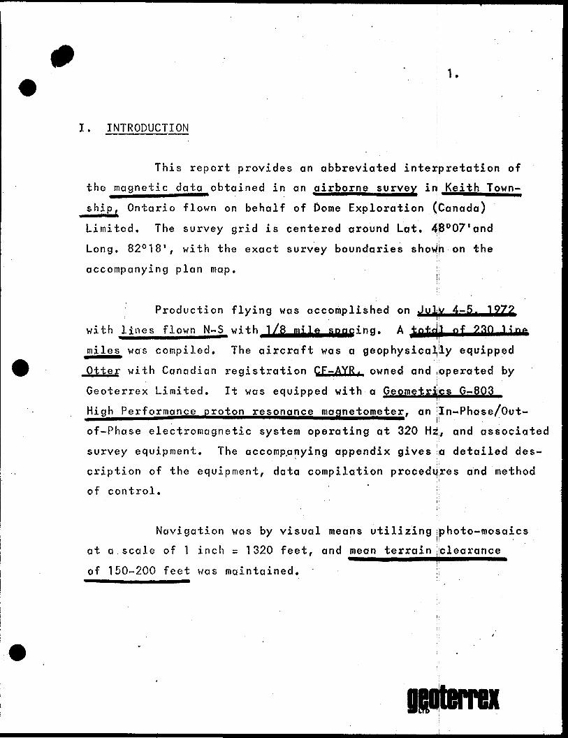
I. INTRODUCTION
This report provides an abbreviated interpretation of
the magnetic data obtained in an airborne survey in J^eithjown-
ship, Ontario flown on behalf of Dome Exploration (Canada)
Limited. The survey grid is centered around Lat. 48007'and
Long. 82 0 18', with the exact survey boundaries shoWh on the
accompanying plan map.
Production flying was accomplished on
with lines flown N~S^ with JL/S-jgjl^.sjmg i n g . A jjfljjjjj 93ft
miles was compiled. The aircraft was a geophysieally equipped
Otter with Canadian registration CF-AYR,. owned and operated by
Geoterrex Limited. It was equipped with a Geometrics G-803
High Performajice^proton reson^^eitiaat'ie'toitneter, an In-Phase/Out-
of-Phase electromagnetic system operating at 320 Hz, and associated
survey equipment. The accomp.anying appendix gives a detailed des
cription of the equipment, data compilation procedures and method
of control.
Navigation was by visual means utilizing photo-mosaics
at a scale of 1 inch = 1 320 feet, and mean terrain clearance
of 150-200 feet was maintained.
D&oteirex
scale of 1 inch s T 390
2.
drafted on a base rjiap at a
interva.f20auS are drawn
wherever possible. Values shown represent relative field
intensities. .
II. PERSONNEL
The personnel involved in this survey include:
A. Field Operation
Pilot
Navigators
Operators
Data Compilers
Aircraft Engineer
Geophysicist
A. Bratteng, Ottawq, Ontario
L. Mathews, - " "R. Bolivar,
B. Kremer, S. Harrison,
M H
C. Taggart, " "
L. Fougere, " "
D. Wagg, Manotick, Ontario
B. Office Compilation
Data
Drafting
Geophysics
D. Sarazin, Ottawa,
M. Dostaler "
D. Wagg, Mqnotipk,R. Dowse, Ottawa,
ORtterrex
f4.
III. CLAIMS COVERED
322707-322732327597-327598333434-333437340967-340987341603-341604341626-341630341979-342008344440-344442353733-353738353804-353815354009-354010354859-354863
i.ncl.M
II
II
II
II
II
II
H
II
II
II
Total s 1 18 claims
5.
IV. INTERPRETATION
The magnetic pattern in the north half of the survey
area is for the most part moderately active, tind rflther suggestive
of mafic to intermediate metavolcanics. The density of axes varies
gradually from low to moderate, while relative amplitudes of
200-500 gammas are most common. The magnetic features prefer an
easterly strike, although localized sections depict NE-SW
trends as well.
Scattered throughout the metavolcanics atfe several
magnetic markers of interest, the most prominent being a long,
highly magnetic easterly trending belt considered to be part
of a known iron formation. The belt widens gradually from
west to east, with relative amplitudes showing a maximum relief
above the region^j^^b^^Jiarojjjid oJ 650Q gammas*
One mile south of this formation lies another belt of
interest. It is less continuous with more moderate amplitudes
(1200-2500 J) suggesting a disrupted region of mafic intrusives..
Some interesting EM responses were also identified in the
vicinity of these markers, particularly on the northern flanks.
The south part of the survey area is less active
magnetically, and a zone of quartz monzonite mapped by geology
conforms very well with a quiet magnetic pattern i h t he southwest
6.
quadrant. The wedge-shaped zone of felsic to intermediate
metavolcanics (mainly tuff) is also outlined by magnetics
reasonably well in the west, south and 'north, but the magnetic
pattern suggests the zone of tuffs could well continue farther
to the east.
Faulting and shear zones with easterly strikes are
expected in this region, and some N-S and NW-SE lineations
can also be inferred, especially in the south where the magnetic
axes are highly disrupted and offset. Some of these ruptures
relate quite well to interesting EM prospects.
Respectfully submitted,
D. M. Wagg, P. Eng. ,
R. K. Dowse, B. A.
fl&oterrex
9APPENDIX
Following is a description of equipment and procedures used during this airborne geophysical survey.
A. EQUIPMENT
1) Aircraft;
The aircraft is a deHovillond Otter DHC-3 with Canadian registration CF-AYR. This aircraft is a single engine, slow speed, high performance type with a gross weight of 8,000 Ibs. The aircraft may be equipped with wheels, skis, or floats, as required. Normal survey speed is 100 miles per hour* M*
2) Electromagnetometer;
The electromagnetic unit is a Rio Tinto type, measuring In-Phase and Out-of-Phase components of the secondary field at a frequency of 320 cycles per second* The unit was de signed and built by Geoterrex, and carries Serial #1.
A transmitter generates a closely controlled sine wave of 320 cps which is amplified and fed to a transmitting coil mounted on the starboard wing-tip. This coil is iron cored and has vertical windings, with coil axis in the direction of flight. The circulating coil power is some 5000 volt amperes.
A receiving coil is mounted on the port wing, co-planar with, and 62 feet from, the transmitting coil. The voltage developed in the receiver coil due to the transmitted field is some 300 millivolts. In the absence of external conduc tors, this voltage is cancelled by a reference voltage de rived directly from the transmitter voltage.
When the aircraft comes within range of a conductor, the normal (or primary) field is changed by a secondary field, and the resultant voltage at the receiver coil is amplified and passed on to the EM receiver in the aircraft. This signal is filtered and split into one component in-phase and one component out-of-phase with reference to the transmitter voltage. The signals are then passed through phase-sensitive detectors where their amplitudes may be read on meters, or
2.
recorded on a chart. A time constant of 2.0 seconds is used for the recording of these responses. A system of calibra tion is included so that amplitude of responses (anomalies) may be determined in "parts per million" of the primary receiver coil voltage prior to cancellation. Noise level of the system due to movement of the metal aircraft within the EM field is normally 50 parts per million or less. Signifi cant conductors depending on distance and size, will produce anomalies of more than 50 parts per million.
The system is equipped with a third independent channel which may be used to measure spurious electrical noise (independent of EM noise) at any selected frequency. It is frequently used to display a second in-phase response at a time constant of 0.6 seconds which enables improved resolution for comparison with the normal responses.
An accelerometer is also installed and the output recorded on the 8-channel recorder. This indicates vertical motion of the aircraft and enables discarding of false anomalies which could result from aircraft flexure.
Calibration marks are displayed on the eight-channel chart, and are approximately 15 millimeters for 200 parts per million.
Any anomalies noted are listed in Appendix A bf this report, indicating position, (fiducial number on the path recovery camera), amplitudes, aircraft altitude, magnetic relationship if any, relative anomaly rating, and comments which may be of significance.
The anomalies are then plotted on the base map in coded form, according to the legend accompanying this Appendix. Anomaly groups which reflect probable ground conductors are circled and numbered. These are described and discussed in the report in the context of geophysical and where possible, geological significance.
3) Magnetometer:
The magnetometer used is a Geometric.S-JlcjiaX-Gai8(I3. Proton Resonance type incorporating a High Performance option.
giBrterrex
Recording times are variable, from three times per second to once per 2 seconds, with respective sensitivities of 2 gammas to 0.5 gamma. In normal use readings are obtained once per second with o sensitiyj^ty^ of l flojnjno-^
The sensing head is a toroidal coil immersed in a special hydrocarbon fluid and mounted beneath the port wing*
The magnetometer is a d^g^taJLrejordoijtijrijy^flnd output is used to drive a paper recorder (Hewlett Packard Model 5050-B). In addition analogue outputs are fed to the eight- channel recorder for direct comparison with the electro magnetic results, and to a Hewlett-Packard Model 680 - six inch rectalinear strip recorder.
Jull scale deflection usually used in mineral surveys is JOOOgammas although other sensitivities are available. Automatic stepping of the full scale analogue deflection is incorporated. Recordings made on the paper *ape are the values of the total field intensity.
Contouring of results is accomplished as desired.
4) Spectrometer;
An Exploranium DGRS-1000 spectrometer is optionally carried on the Otter, along with a sensing head containing either three 6" x 4" Sodium Iodide crystals, or a single 8" x 4" crystal.
This is a four channel differential gamma-ray unit measuring energy levels of potassium 40, bismuth 214, thallium 208 and total count.
Time constants and full scale ranges are variable and are selected to suit the conditions and background of the survey area.
Depending on requirements of the survey, one or more channels may be recorded on the eight channel recorder.
Data presentation, if required, is usually in the form of plotted anomalies showing channel intensities and aircraft altitude. Contour maps of one or more channels may be pro duced in special circumstances.
O!
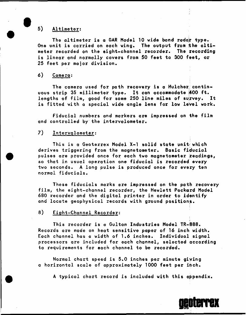
t5) Altimeter;
The altimeter is a GAR Model 10 wide band radar type. One unit is carried on each wing. The output from the alti meter recorded on the eight-channel recorder. The recording is linear and normally covers from 50 feet to 300 feet, or 25 feet per major division.
6) Camera;
The camera used for path recovery is a Hulcher contin uous strip 35 millimeter type. It can accommodate 400 ft. lengths of film, good for some 250 line miles of survey. It is fitted with a special wide angle lens for low level work.
Fiducial numbers and markers are impressed on the film and controlled by the intervalometer.
7) Intervalometer;
This is a Geoterrex Model X-1 solid state unit which derives triggering from the magnetometer. Basic fiducial pulses are provided once for each two magnetometer readings, so that in usual operation one fiducial is recorded every two seconds. A long pulse is produced once for every ten normal fiducials.
These fiducials marks are impressed on the path recovery film, the eight-channel recorder, the Hewlett Packard Model 680 recorder and the digital printer in order to identify and locate geophysical records with ground positions.
8) Eight-Channel Recorder;
This recorder is a Gulton Industries Model TR-888. Records are made on heat sensitive paper of 16 inch width. Each channel has a width of 1.6 inches. Individual signal processors are included for each channel, selected according to requirements for each channel to be recorded.
Normal chart speed is 5.0 inches per minute giving a horizontal scale of approximately 1000 feet per inch.
A typical chart record is included with this appendix.
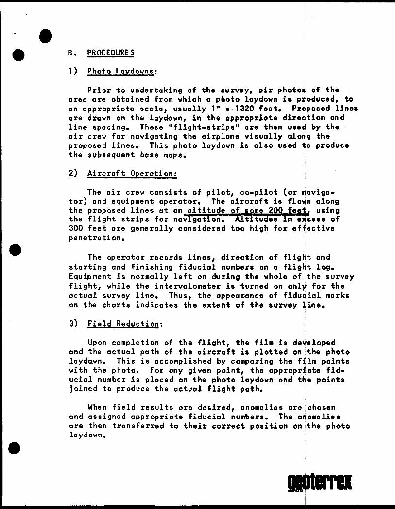
B. PROCEDURES
1) Photo Laydowns;
Prior to undertaking of the survey, air photos of the area are obtained from which a photo laydown is produced, to an appropriate scale, usually 1" s 1320 feet* Proposed lines are drawn on the laydown, in the appropriate direction and line spacing. These "flight-strips" are then used by the air crew for navigating the airplane visually along the proposed lines. This photo laydown is also used to produce the subsequent base maps.
2) Aircraft Operation;
The air crew consists of pilot, co-pilot (or naviga tor) and equipment operator. The aircraft is flown along the proposed lines at an altitude of some 200 feej. using the flight strips for navigation. Altitudes in excess of 300 feet are generally considered too high for effective penetration.
The operator records lines, direction of flight and starting and finishing fiducial numbers on a flight log. Equipment is normally left on during the whole of the survey flight, while the intervalometer is turned on only for the actual survey line. Thus, the appearance of fiducial marks on the charts indicates the extent of the survey line.
3) Field Reduction:
Upon completion of the flight, the film is developed and the actual path of the aircraft is plotted on the photo laydo.wn. This is accomplished by comparing the film points with the photo. For any given point, the appropriate fid ucial number is placed on the photo laydown and the points joined to produce the actual flight path.
When field results are desired, anomalies are chosen and assigned appropriate fiducial numbers. The anomalies are then transferred to their correct position on the photo laydown.
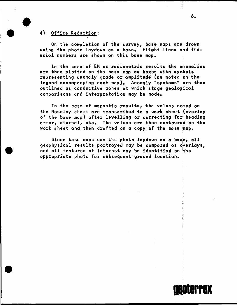
4) Office Reduction;
On the completion of the survey, base maps are drawn using the photo laydown as a base* Flight lines and fid ucial numbers are shown on this base map*
In the case of EM or radiometric results the anomalies are then plotted on the base map as boxes with symbols representing anomaly grade or amplitude (as noted on the legend accompanying each map). Anomaly "systems" are then outlined as conductive zones at which stage geological comparisons and interpretation may be made*
In the case of magnetic results, the values noted on the Moseley chart are transcribed to a work sheet (overlay of the base map) after levelling or correcting for heading error, diurnal, etc. The values are then contoured on the work sheet and then drafted on a copy of the base map*
Since base maps use the photo laydown as a base, all geophysical results portrayed may be compared as overlays, and all features of interest may be identified on the appropriate photo for subsequent ground location.
O&oterrex
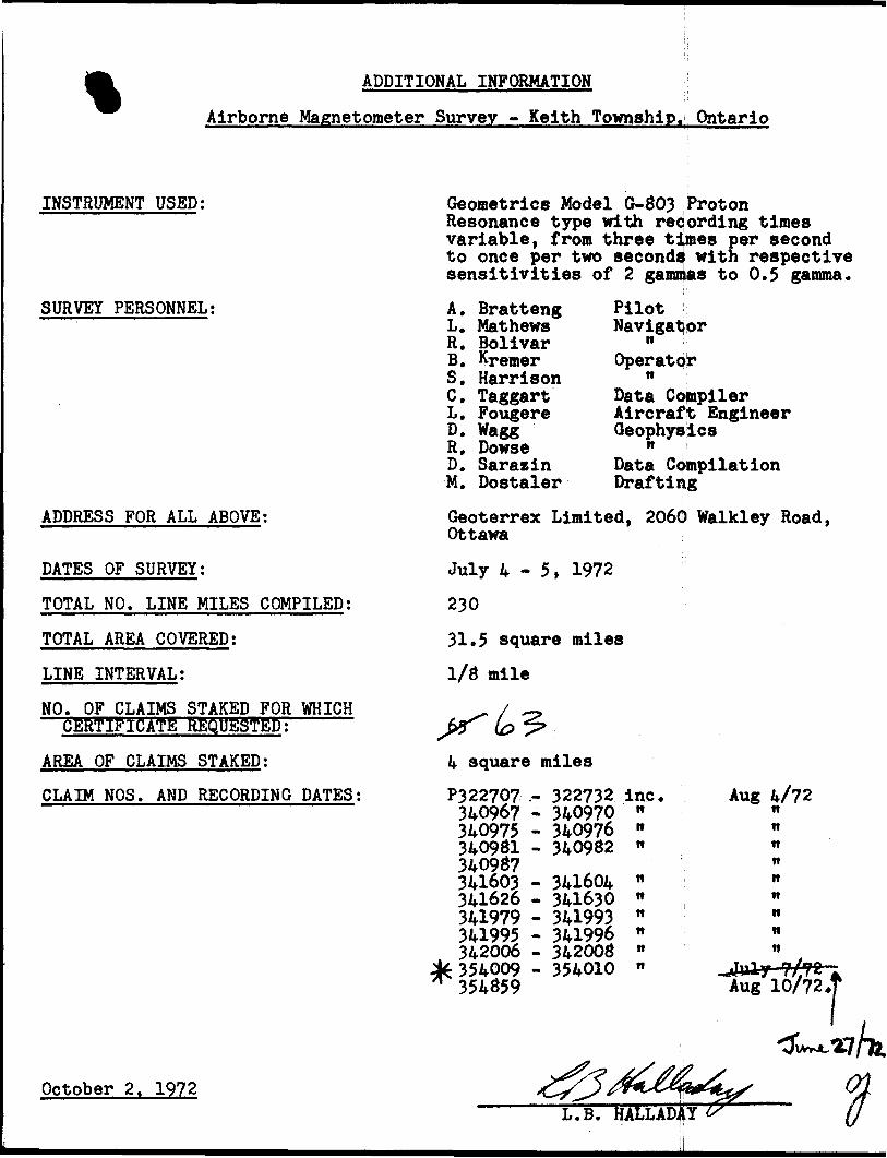
ADDITIONAL INFORMATION
Airborne Magnetometer Survey - Keith Township. Ontario
INSTRUMENT USED:
SURVEY PERSONNEL:
ADDRESS FOR ALL ABOVE:
DATES OF SURVEY;
TOTAL NO. LINE MILES COMPILED;
TOTAL AREA COVERED;
LINE INTERVAL;
NO. OF CLAIMS STAKED FOR WHICH CERTIFICATE REQUESTED;
AREA OF CLAIMS STAKED;
CLAIM NOS. AND RECORDING DATES:
October 2. 1972
Geometrics Model G-803 Proton Resonance type with recording times variable, from three times per second to once per two seconds with respective sensitivities of 2 gammas to 0.5 gamma.
A. Bratteng L. Mathews R. Bolivar B. Kremer S. Harrison C. Taggart L. Fougere D. Wagg R. Dowse D. Sarasin M. Dostaler
Pilot Navigator
nOperator
nData Compiler Aircraft EngineerGeophysics
nData Compilation Drafting
Geoterrex Limited, 2060 Walkley Road, Ottawa
July 4-5, 1972
230
31.5 square miles
mile
square miles
P3 22707 .- 340967 - 340975 - 340981 - 340987 341603 - 341626 -341979 - 341995 - 342006 -354009 - 354859
322732 inc.340970 "340976 "340982 "
341604 M341630 "341993 n341996 "342008 "354010 "
Aug 4/72 ttttn n n n tt n n
lit W* J f 11 f *" A
Aug 10/72 .t
L.B. HALLADJiT
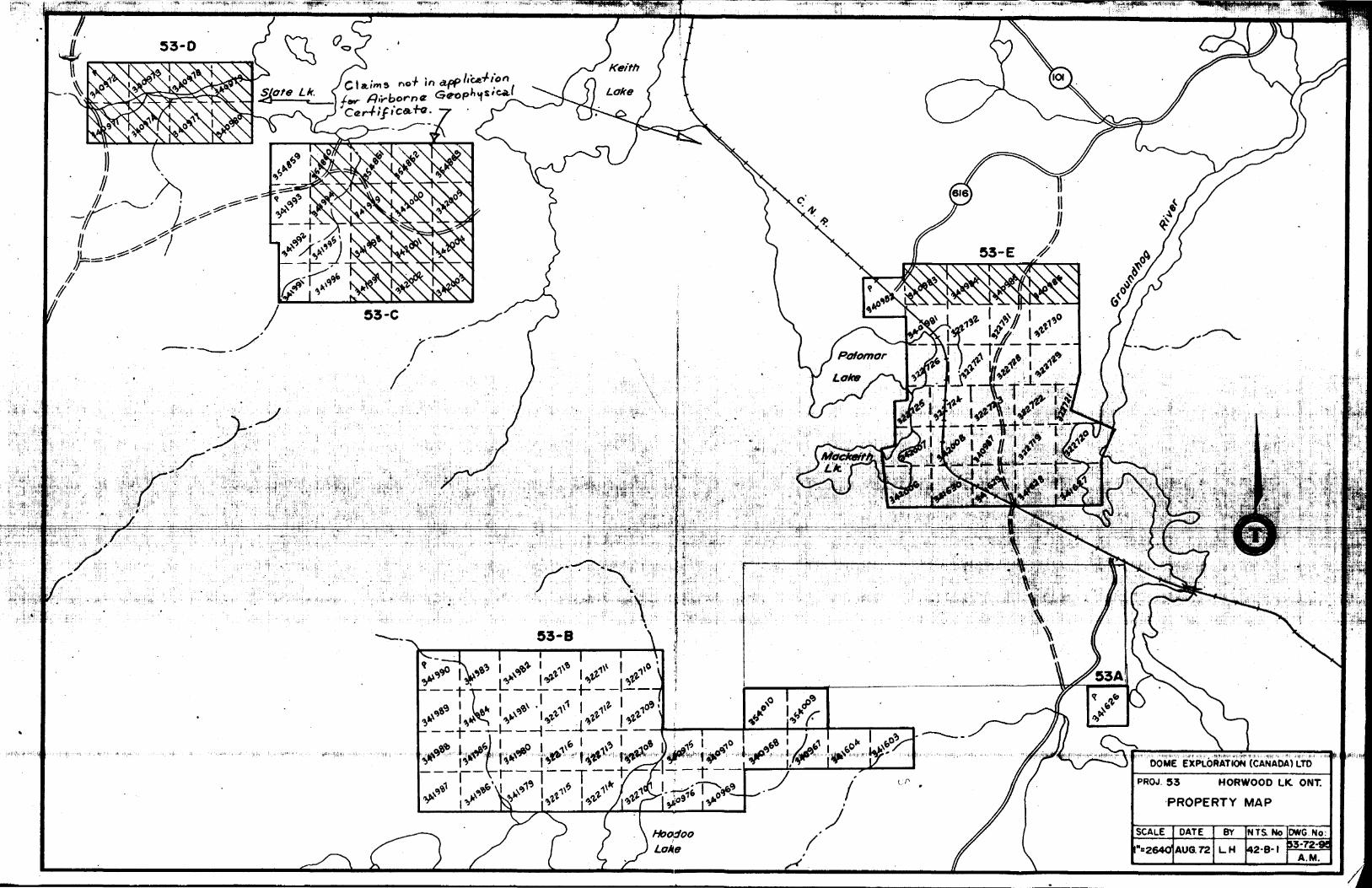
DOME EXPLORATION (CANADA) LTD
PROJ. 53 HORWOOD LK. ONT.
PROPERTY MAP
264OIAU6.72
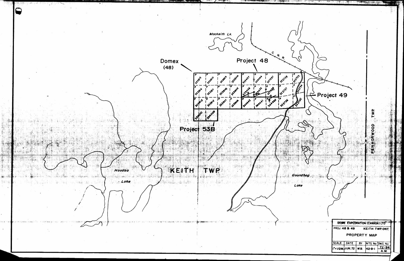
Project 48Domex (48)
f i/ \ S\*
s \s.\s\s Project 49
SCALE DATE BY NTS. No DWG No
,,;-U^-i'^'^-V 'J- K'
TRIM L INE
f *V ' V-ir" -. *v,. . ,)fri
?fr* ." x .' * v'y- *V . ' ^ ' h/- r, - LC a. A
.:^Hj".
' *i
X- *v*;K
H* •"^ -- *
• in?
- *S- ^ l;"- ^ ' ' '-' i•-fe ?:i i ii- li ^ *- ^ A*,;.*
^
^^T
, HTV-
'.^^...^f
^Muskego Twp. (M-881)
Lake
7.5M- ,-
ftM- :-
4.5 M ~-
3*- -
I.5M
2 J 2 761
. .- 1" •••' ' i f 1
' 2927B2I
P . ' L34O973 |
'.40972 f 1Lv-,.^v:-iv 1\A ,
140971 | 34O97 4 'J i 1
293535 (340 97 B ' 3409^
^L^^ _ -^Z^Lp ~ pV" ~ "~
340977
V — ,340960
7.5M
P R
332780 320061•~ — — — — -* —P P
33Z781 320062
|P IP. JP "^P 1 1 ? | ! | pi ! p f1292808 292807 .2928061 29a805 1 2^2801 l 29^801 | 292 602
— .^— — —— — - —— \ —— —— —— — - l— — —— —— - -* —— —— ' —— —— —— -** - —— ——— ^ ~ —— ——— ™ —— ~ -—— — - —i p. IP t I P. ip!i i , ' ' -i ' i i.292809 i292S!O i 292811 , 29
i p* i p. ip1 : 1 1
,; j 292814 (29/BI5 2812 X9?SI3 -i " ! - —
/6M
4.5M
1212799 l 292800' 292801 1333136
301335 ' 301132 l J409H2X ^40981
322 [726|HI32'2727 )3227?8
i ^,. r - 7^W,
\ /tor 951
327*9,7 , ~ l " i T "1
f*ai4 l 353811 l 353808 ,353B05— — , .l -. — Groundhog
River353736 3V/3735; ,
1322716 |3227l4 (322703
.340S67 |34I604 (34(603
Groundhog
7293642 293641 , 293640 29 3^38
P
IOin O
ex 5
"DO O
Ib-o•ii!!
336Armstrong
Horwood Twp.(M-936)
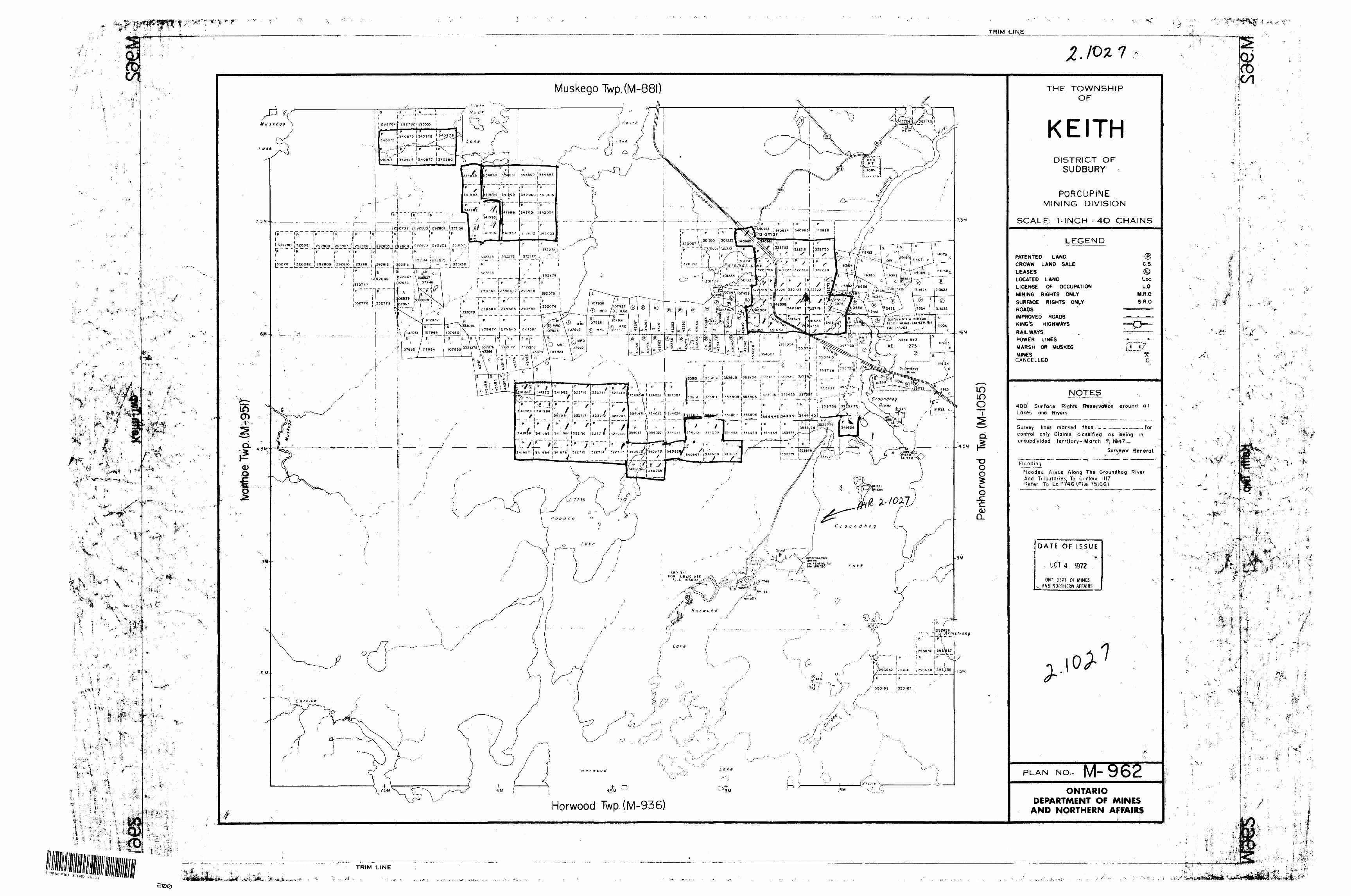
PATENTED LANDCROWN LAND SALE
LEASESLOCATED LANDLICENSE OF OCCUPATION
MINING RIGHTS ONLY
SURFACE RIGHTS ONLYROADSIMPROVED ROADSKING'S HIGHWAYS
RAILWAYS
POWER LINESMARSH OR MUSKEG
MINESCANCELLED
Lakes and R ivers
' •'^, . . " - ' r"
? m B * ^f * T** v ^^^^^ ^^^ m '-*i.
'' , '
rOWNSHlP OF
ilTHRICT OFIDBURY
ICUPINE^ DIVISION
CM 4O CHAINS
EGEND
i C.&©Loc
PAT ION L.O.LY M.ROINLY S.RO
~g~^
V '
"^^ *
C.
fs fR*serVt#on around all
d th^s ' forclassified as being in
ry- March T, 1*47-s ' r
Syrveybr General.- — .- ^^r ~ — -^-" - ""-—' .— -.--.. i .1 — , — v -- -^ — ™"-"-*- F
1
it l ]
j
t;?
'
i
•\ ' ! s-
' " ,- 1-" S f
; ' * 1'
i^.,, ;^i" ;T
'i- ^
L rf-' ^ 'i
i
' " v ^-^
kL
\
" '' \ - ^ ' '""?" . . ' :
K? ' " ^ -' : '-" '"S -
\ ^ '\Af?'
, f '- t .Flooding
Flooded Aieus A long The G roundhog River And Tributaries, To Contour 1117 7efer To Lo 7746 (File 75166)
DATE OF ISSUE
UCT 4 1972
ONr OEPT Or MINES v AND NORTHERN AFFAIRS
l0^ 1
4;
V:
.j*
PLAN NO.- M-962 \
ONTARIODEPARTMENT OF MINES
AND NORTHERN AFFAIRS
' '-i j- ~
TRIM LINE
t"4S
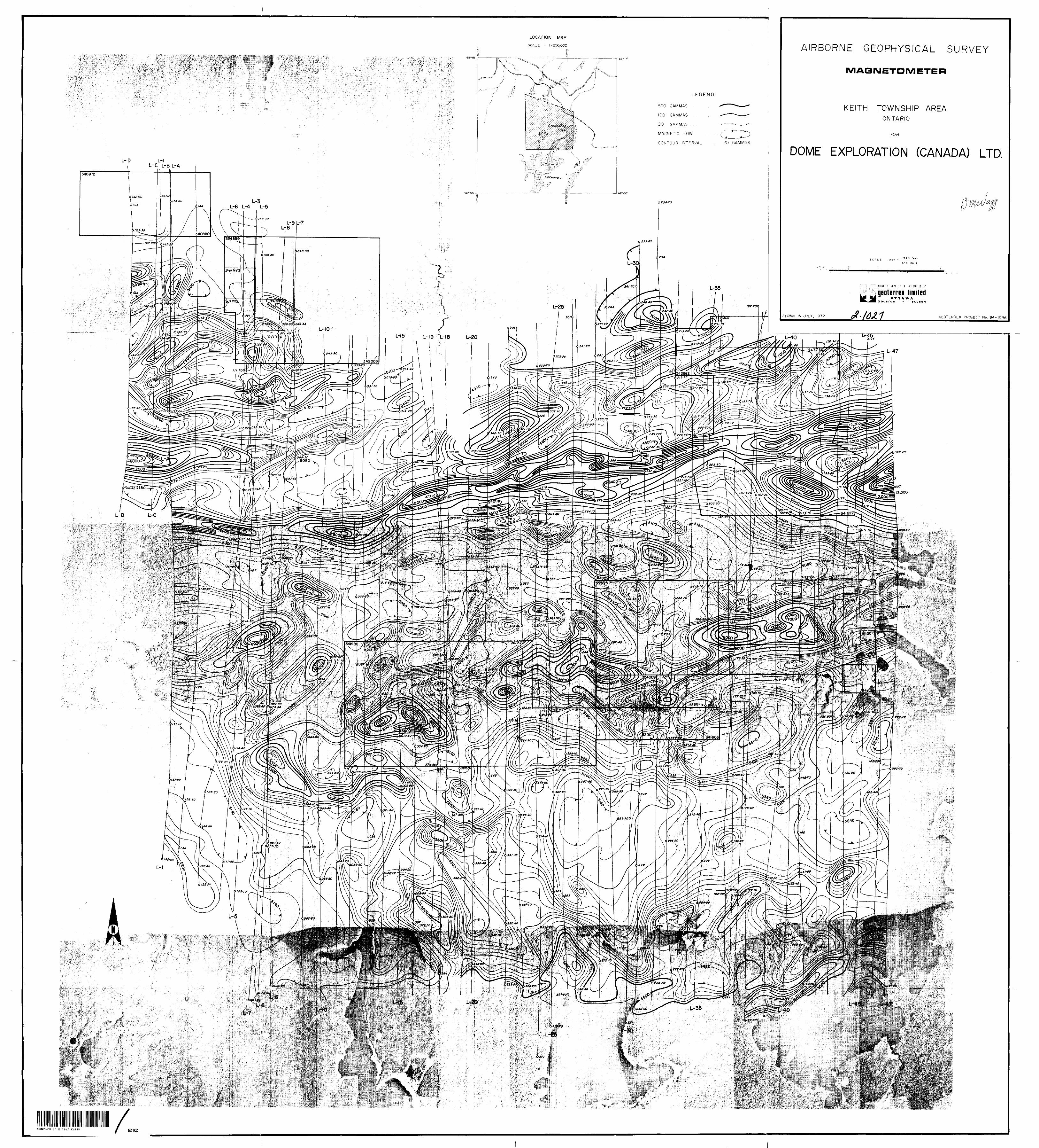
LOCATION MAP
SCALE - 1/250,000 AIRBORNE GEOPHYSICAL SURVEY
MAGNETOMETER
KEITH TOWNSHIP AREAONTARIO
FOR
DOME EXPLORATION (CANADA) LTD.
500 GAMMAS
100 GAMMAS
20 GAMMAS . .
MAGNETIC LOW .
CONTOUR INTERVAL 20 GAMMAS
L- L-C L-B L-A
L-3 L-6 L-4 L-5
geoterrex limited
FLOWN IN JULY, 1 972 GEOTERREX PROJECT No. 84-I04A
L-19 -. L-18
s^-^\235- TO
4600-^)242 30