Embed Size (px)
Citation preview

Report of the investigation of
the accident resulting in one fatality and one serious injury
during the mooring of the motor yacht
JEMASA
in Phuket, Thailand
on 18 February 2009.
Maritime Authority of the Cayman Islands Strathvale House
North Church Street PO Box 2256, George Town
Cayman Islands KY1-1104
Casualty 01/2009
NOTE
The fundamental purpose of investigating an accident under the Cayman Islands
Merchant Shipping Law, as amended, is to determine its circumstances and the cause
with the aim of improving the safety of life at sea and the avoidance of accidents in
the future. It is not the purpose to apportion liability, nor, except so far as is
necessary to achieve the fundamental purpose, to apportion blame.
This report is not written with liability in mind and is not intended to be used in court for the
purpose of litigation. It endeavours to identify and analyse the relevant safety issues
pertaining to the specific accident, and to make recommendations aimed at preventing
similar accidents in future.

Page 3 of 36
Report of the investigation of the accident resulting in one fatality and one serious injury during
the mooring of the motor yacht JEMASA in Phuket, Thailand on 18 February 2009.
SYNOPSIS
On 18 February 2009, the motor yacht JEMASA was mooring at a Yacht Haven
Marina in Phuket, Thailand after returning from a voyage to Langkawi, Malaysia.
Wind and tidal conditions were benign and mooring followed the yacht’s normal
routine. When four lines had been made fast ashore, a crew member placed the
bridge wing controls in the “full ahead” position and closed the control station.
Both engines were still running, but in the idle mode, and the action of putting the controls to full ahead
engaged the propellers and the yacht moved ahead. The yacht broke free of its moorings. No mooring
ropes parted but three of the mooring points in use on the quay failed. Two bystanders were struck by
flying debris and / or recoiling mooring ropes. One person was hit in the legs and the other was hit on
the head. Both were evacuated to hospital where the person struck in the legs underwent reconstructive
surgery. The person struck in the head remained in a critical condition and died five days later.
After the moorings failed, manoeuvring control was taken by the main bridge manoeuvring station and
the yacht quickly brought under control. The yacht was then safely moored back alongside the quay.
Due to the design of the bridge wing control station, it was necessary to put the engine controls in the full
ahead position before the control station could be closed.
In an effort to prevent a repeat of this accident, recommendations have been issued relating to the
design of bridge wing control stations on yachts, the importance of proper procedural controls for
mooring operations and the implementation of safety management systems under the ISM Code.
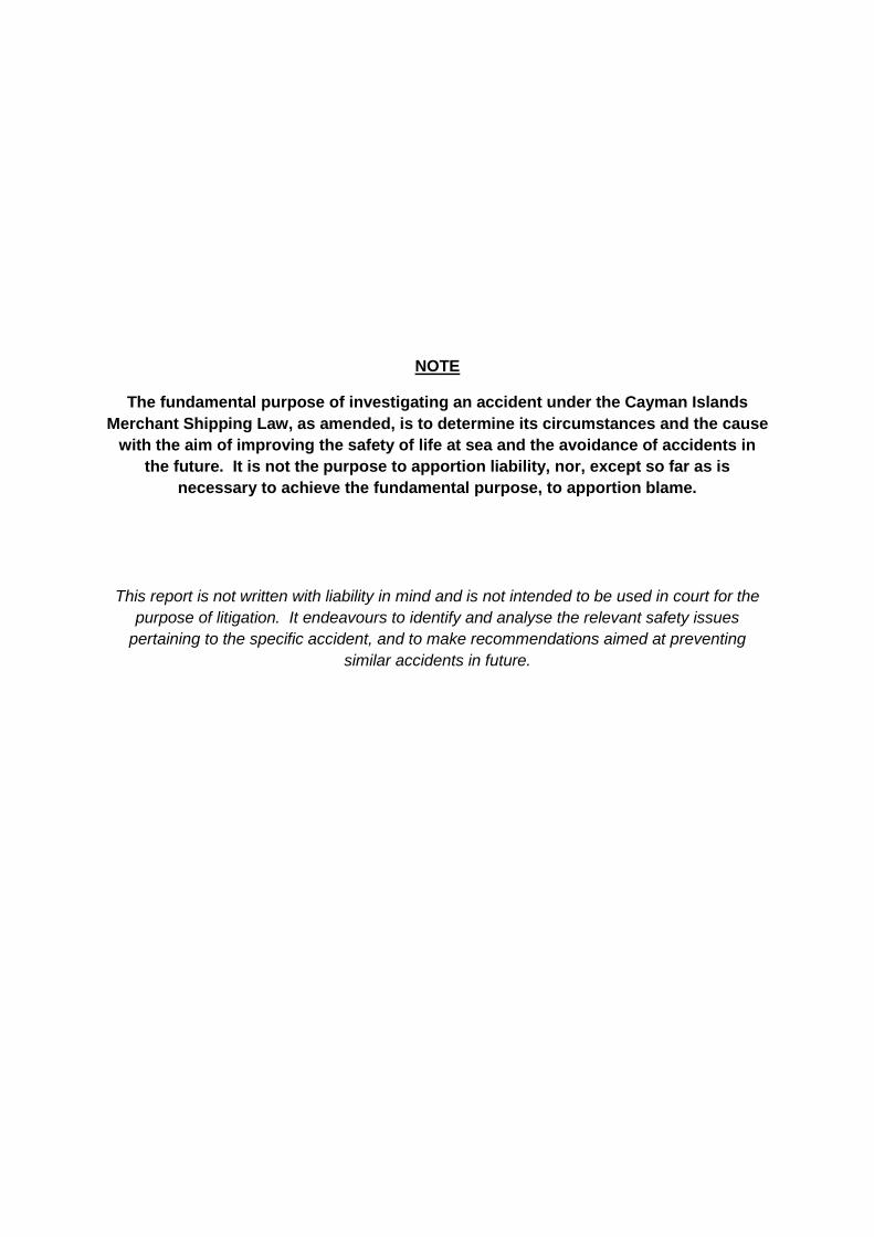
Page 4 of 36
JEMASA alongside in Ko Phuket, Thailand
Page 5 of 36
Glossary of Abbreviations, Definitions and Acronyms
Company means the owner of the ship or any other organization or person
such as the manager, or the bareboat charterer, who has assumed
the responsibility for operation of the ship from the owner of the
ship and on assuming such responsibilities has agreed to take
over all the duties and responsibilities imposed by the ISM Code1.
CISR Cayman Islands Shipping Registry
DOC Document of Compliance
DP Designated Person under the ISM Code. A person with access to
the highest level of management and with authority and
responsibilities relating to safety and pollution prevention.
IMO International Maritime Organization
ISM Code International Safety Management Code
kW Kilowatt
length for the purpose of this report, length in relation to a vessel, is taken
as the length measured between extremes, including bowsprits
and stern davits/marlin boards2.
LL Convention International Convention on Load Lines, 1966 and Protocol of
1988, as amended
LR Lloyd’s Register
MACI Maritime Authority of the Cayman Islands
MSI Marina Systems International Co Ltd.3
SMC Safety Management Certificate
SMS Safety Management System
SOLAS Convention International Convention for the Safety of Life at Sea, 1974 and its
Protocol of 1988, as amended.
STCW Convention International Convention on Standards of Training, Certification
and Watchkeeping for Seafarers, 1978, as amended in 1995 and
1997.
WYM Wilson Yacht Management
1 SOLAS IX/1.2
2 AS 3962 – 2001 Section 1.3.9
3 Not to be confused with Marine Systems International Inc of New Brunswick, Canada.

Page 6 of 36
SECTION 1 – Factual Information
INCIDENT PARTICULARS
Vessel details:
Vessel Name : JEMASA
IMO Number : 1008009
Ship Manager : Wilson Yacht Management
Port of registry : George Town
Flag : Cayman Islands
Type : Motor Yacht
Year of build : 2002 by Hakvoort Shipyard; Monnickendam, Netherlands.
Delivered : April 2006
Classification : Lloyd’s Register
Length (overall) : 49.99 meters
Gross Tonnage : 696
Engine Power : 2028 kW
Number of propellers : 2
Accident details:
Time and date : 1710L on 18 February 2009
Location : “Yacht Haven Marina”, Phuket, Thailand
Fatalities / injuries : One fatality, one serious injury.
Damage : Minor damage to yacht hull. Damage to shore side
mooring arrangements.

Page 7 of 36

Page 8 of 36
NARRATIVE
(all times are “local”.)
Prior to the accident
During February 2009, JEMASA was based at the Yacht Haven Marina on Ko Phuket, Thailand. The
yacht was not engaged in charter activities and the beneficial owner or family were not onboard. A visit
by potential yacht brokers had been arranged for the weekend of 21 / 22 February.
16 February 2009
On Monday 16 February 2009, JEMASA left Yacht Harbour Marina for a voyage to Langkawi in
neighbouring Malaysia. The voyage was to enable JEMASA to take on fuel oil and duty free stores. In
addition, visa restrictions made it necessary for crew members to leave Thailand every 30 days.
Langkawi lies approximately 150 nautical miles South East of Phuket and is a popular destination for
yachts based in Phuket making so called “Immigration Runs” to comply with Thai visa requirements.
17 February 2009
JEMASA arrived in Langkawi anchorage at 08:00 on the morning of 17 February 2009. Crew passports
were sent ashore to clear immigration formalities and JEMASA took on 30,000 litres of fuel oil from a
bunker barge. After bunkering was complete the yacht spent the rest of the day alongside in the Royal
Langkawi Yacht Club before departing for Ko Phuket at approximately 04:00 on 18 February 2009.
18 February 2009
The departure time of 04:00 was chosen so that the yacht’s return to Yacht Haven Marina would
coincide with the high tide at 17:00 on 18 February 2009. When the yacht was approximately one
nautical mile from the marina, the master telephoned the marina manager to arrange for line handlers
and to confirm the minimum water depth at the quay. The marina manager confirmed that he had
JEMASA in sight and told the master that there would be at least 1m of under keel clearance as
JEMASA entered the marina. Satisfied that appropriate arrangements were in place for mooring, the
master slowed JEMASA to manoeuvring speed and transferred engine and steering control to the port
bridge wing. JEMASA was manoeuvred alongside “port side to” without incident and four lines were
secured ashore.
During the mooring operations, a single deckhand was manning the mooring station on the foredeck. As
it is not possible to observe the strain and position of mooring ropes when operating the forward mooring
winches, the deckhand was operating under the supervision of the master who was directing operations
from the port bridge wing. With both forward lines secure the deckhand then moved aft to the bridge,
while the master entered the bridge to order the engines shutdown with the yacht now moored
alongside. The marina manager who was present on the quayside described the manoeuvring and
docking as extremely competent and professional.
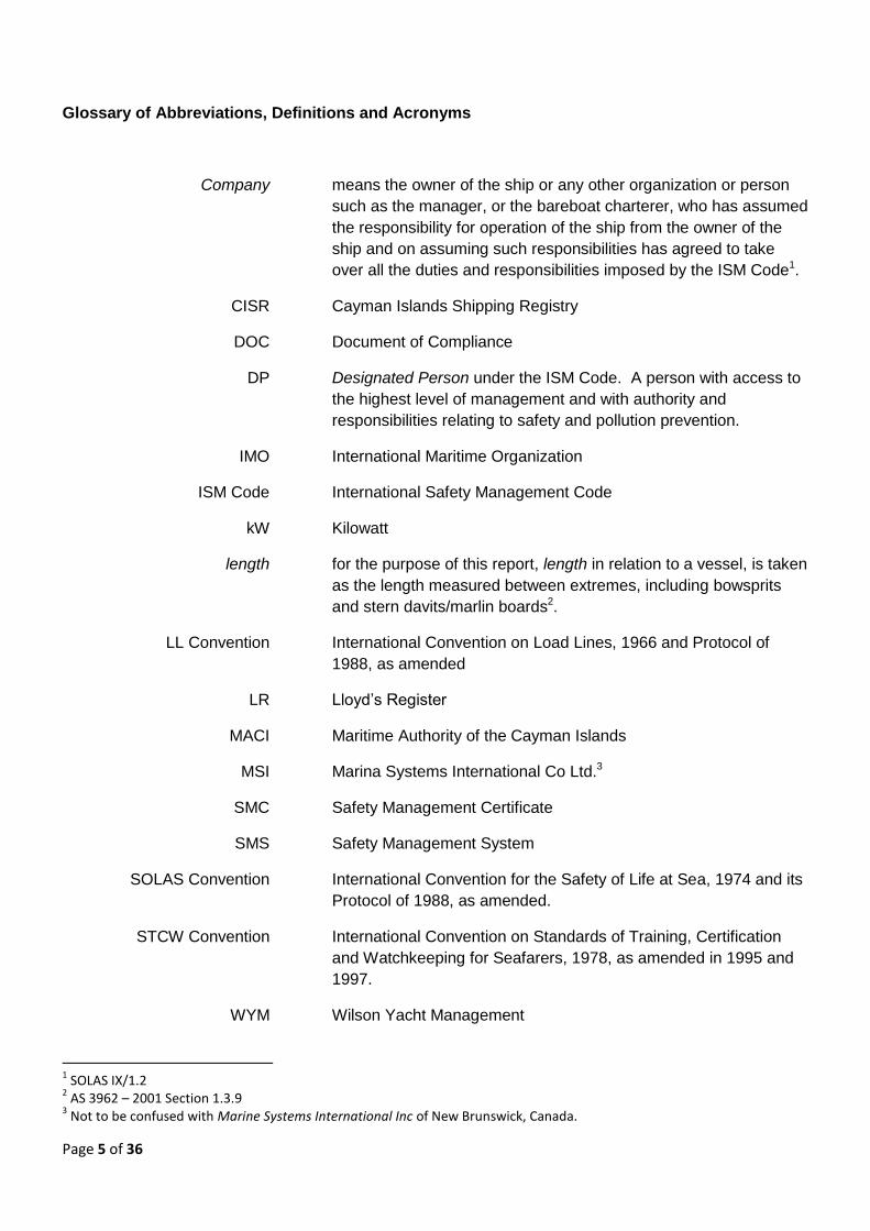
JEMASA has two bridge wing control stations that fold into the deckhouse when not in use. When the
wing stations are deployed they extend the whole width of the walkway at bridge level and impeded fore
and aft movement on their side of the yacht. (See figure 1)
Page 9 of 36
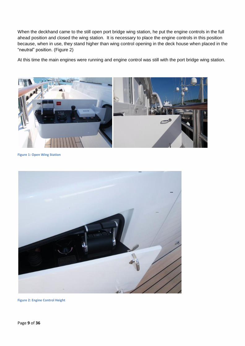
When the deckhand came to the still open port bridge wing station, he put the engine controls in the full
ahead position and closed the wing station. It is necessary to place the engine controls in this position
because, when in use, they stand higher than wing control opening in the deck house when placed in the
“neutral” position. (Figure 2)
At this time the main engines were running and engine control was still with the port bridge wing station.
Figure 1: Open Wing Station
Figure 2: Engine Control Height

Page 10 of 36
The accident
When the engine controls were placed in the full ahead position the engines engaged and proceeded to
power the yacht up the quay. At this point the deckhand was alerted by shouts from the quayside that
the yacht was “in gear” and putting strain on the mooring ropes. The deck hand then reopened the
bridge wing controls and brought the control levers back to neutral. At the same time, the master took
engine control from the bridge and placed the engines astern to arrest the forward movement of the
yacht. The action of the master was unable to bring the yacht to a stop before three of the mooring
ropes pulled their attachment points from the quayside. The yacht was brought under back control,
manoeuvred alongside and then made fast once again. At this time the engines were shut down.
Witnesses on the quayside and onboard JEMASA report hearing a “crushing noise” and seeing JEMASA
moving up the quay and making contact with two yacht tenders that were moored directly ahead of
JEMASA, forcing them off the quay. The three mooring ropes that were pulled from the quay recoiled
violently. See Appendix 2 or details of the mooring arrangements and damage to the quay side.
Two persons on the quayside were struck by flying debris and / or recoiling mooring ropes and knocked
to the ground. Victim 1 was a shore worker from a nearby yacht and sustained leg injuries, while Victim
2, who sustained head injuries, was a sixteen year old girl visiting friends of her parents in Yacht Haven
Marina.
The immediate response to the accident
Berthed next to JEMASA was the support craft SURI4. Crew members from SURI were on the dock
when the accident occurred and raised the alarm with the local ambulance authorities. Ambulances
were also called from the marina office. A crew member from SURI who had been trained as an armed
forces medic began to provide first aid to the injured persons. Victim 1 was conscious but in obvious
pain and distress. Victim 2 was unconscious and suffering from traumatic injuries. Medical supplies
from both SURI and JEMASA were made available on the quayside.
Also in the marina at that time were three vacationing medical doctors who quickly arrived on the scene
and took charge of the medical care of the injured.
It was obvious to those in attendance that the Victim 2 was in a serious condition and as SURI carries a
helicopter; preparations began to fly the Victims directly to hospital without waiting for the arrival of local
ambulances. Unfortunately, it was not possible to obtain the necessary air traffic control permissions to
launch the helicopter in the time available.
About 35 minutes after the accident, ambulances arrived and the injured were transferred to hospital in
Phuket along with the doctors who had taken over the initial treatment of the injured persons. Victim 1
had sustained fractures to his legs and required reconstructive surgery in Phuket. Victim 2 had
sustained severe head injuries. She remained unconscious and unresponsive in a coma for 5 days. Life
support was withdrawn on 23 February 2009 and she was pronounced dead shortly afterwards.
4 SURI is the support craft for JEMASA. SURI extends the range and facilities of JEMASA by carrying additional small craft
(including a helicopter), stores and fuel for JEMASA. See Appendix 3 for an overview of SURI.

Page 11 of 36
THE VESSEL AND COMPANY.
JEMASA was registered as a pleasure vessel of 696 GT and 49.99m overall length. The yacht held all
necessary permissions and certificates to engage in commercial charters. As such, the yacht was
required to comply with the Cayman Islands Merchant Shipping (Vessels in Commercial Use for Sport or
Pleasure) Regulations, 2002. These regulations require, inter alia, that the yacht complies with the ISM
Code and the MCA Large Yacht Code5. At the time of the accident, the yacht held a conditional
“Certificate of Compliance6” issued by LR on 05 February 2009 and valid until 15 April 2009.
As a yacht of over 500GT and certified to engage in commercial charters, JEMASA is required to
implement a Safety Management System under the ISM Code. The yacht held a SMC issued under the
ISM Code by CISR. The Initial ISM audit was carried out in November 2006 resulting in one non
conformity relating to “development of plans for shipboard operations” and one observation relating to
“resources and personnel” being raised.
Wilson Yacht Management act as the Company for JEMASA and have assumed all duties and
responsibilities under the ISM Code. WYM hold a DOC issued under the ISM Code by CISR. The last
audit of WYM preceding the accident was carried out on 05 February 2009. Two non conformities were
raised at this audit relating to “maintenance of ship and equipment” and “resources and personnel”. In
addition, one observation was raised relating to “reports and analysis of non conformities, accidents and
hazardous occurrences”.
THE MARINA
Yacht Haven Marina is a long established yacht marina in Northern Phuket, Thailand. In 2005 the
marina began an expansion program aimed at attracting larger, so called “Super Yachts”. The first stage
of this expansion was the construction of the quay where this accident occurred.
Contractors based in Thailand and Australia were used in the design, construction and installation of the
quay. The marina design and construction was undertaken be Marina Systems International (MSI) with
detail design and verification services being provided by Australia based consulting engineers Patterson
Britton & Partners Pty Ltd.
The quay was designed in accordance with guidelines given in Australian StandardTM AS 3962 – 2001
(Guidelines for the design of marinas), and constructed of mainly imported materials. Mooring cleats
were cast in Australia and mooring bollards fabricated in Thailand. AS 3962 – 2001 sets out guidelines
for the design of marinas suitable for vessels up to 50m in length7. Note 1 of this standards states “This
document is intended for use as a guideline and should not be used as a design specification.”.
The quay is made up of floating concrete pontoons held in place by steel piles driven into the seabed.
Outside the concrete pontoon blocks are soft wood wales which are held in place by rods which run
5 A recognised equivalence to the SOLAS, LL and STCW Conventions for Large Commercial Yachts
6 Full certificate title: “Certificate of Compliance with the provisions of the MCA Code of Practice for Safety of Large
Commercial Sailing and Motor Yachts” 7 AS 3962 – 2001: Section 1.1

Page 12 of 36
through pontoons. Approximately every four pontoon blocks there is a gap to accommodate the steel
piles driven into the seabed. This gap is also utilised for mounting shore power and utility stations.
SIMILAR INCIDENTS AND ACCIDENTS
This is the first such incident that has been reported to MACI. After the preliminary investigation into
this accident was completed, MACI issued a “Flyer to the Large Yacht Industry” highlighting the inherent
dangers involved with mooring operations in general and the specific hazards associated with engine
controls that cannot be stowed in the neutral position. This flyer is included as Appendix 4 to this report.
This flyer was widely circulated in the yacht industry and was reproduced in the September 2009 issue of
Seaways, the magazine of the Nautical Institute. Since publication, MACI has received several unofficial
reports of similar incidents occurring on other yachts. None of these incidents resulted in injury or failure
of mooring equipment, but all concerned engine controls being moved from the neutral position to either
stow the controls or fit weather covers.
It is apparent that this accident was not an isolated incident. Similar occurrences in the past have not
resulted in formal reports being made because serious damage and injury did not occur.
STANDARDS, REGULATIONS AND GUIDANCE FOR MOORING OPERATIONS
SOLAS regulation II-1/3-8 and IMO Circular MSC/Circ.1175 provide requirements and guidance on
towing and mooring equipment onboard ships. These requirements apply to all ships constructed after
01 January 2007. Although not retrospectively applied to JEMASA, the Circular contains pertinent
guidance on methods to calculate “safe working loads”. The mooring equipment and ropes onboard
JEMASA exceeded the minimum recommendations in MSC/Circ.1175.

Page 13 of 36
Page 14 of 36
SECTION 2 – Analysis
AIM
The purpose of the analysis is to determine the contributory causes and circumstances of the
accident as a basis for making recommendations to prevent similar accidents occurring in the
future.
THE RESPONSE
The time from the engines being placed in the full ahead position and control being regained by
the master was only a matter of seconds. The actions of the master and the crew in regaining
control and safely mooring JEMASA back alongside were timely, appropriate and professional.
However, in the seconds when control of JEMASA was lost, three mooring ropes tore free of the
quay and two bystanders were seriously injured by flying debris / recoiling ropes. It was fortuitous
that three medical doctors were in the marina at the time of the accident as the injuries sustained
(especially by Victim 2) were extremely severe and beyond normal ship board medical training.
CONSIDERATION OF CONTRIBUTORY EVENTS
Why were the engine control placed in the full ahead position?
Design Considerations8
Most large yachts are fitted with work stations on the bridge wings for docking the vessel. These
work stations provide the field of vision and controls required for manoeuvring the yacht alongside
a berth, tug operations (if required) and mooring operations. When not in use these stations are
protected from weather by either fitting a cover or (as in this case) storing the control station in a
recess in the deckhouse. A number of designs were examined from a variety of yacht builders and
it was found that many require the engine controls to be moved from the neutral position before the
cover can be fitted or the control station stowed.
One yacht builder stated that this was common in “nine out of ten yachts” and that, prior to learning
of this accident, that it “did not constitute a problem”.
On JEMASA the hazards associated with unintentionally engaging the engines was recognised
and a plastic sign was fitted at the control station which read “BEFORE CLOSING TAKE OVER
CONTROLS TO WHEELHOUSE” (figure 3).
Operational Considerations
This sign would not have been visible to the deckhand as he made his way aft from the foredeck
(figure 4). In addition, the duties of the deckhand did not call for him to be familiar with the control
station layout and he was not required to operate any of the controls.
8 Wing control station layout is given in Appendix 5

Page 15 of 36
Figure 3 View of plastic warning sign
Figure 4: Deckhand's view of console with warning sign obscured

Page 16 of 36
Safety Management System
The ISM Code requires the Company to, inter alia, establish safeguards against all identified
risks9. WYM addressed this requirement through section 9.6 of their documented SMS. Under
“General Ship Board Management” the SMS states “The Master should ensure that a risk
assessment has been carried out to cover all work activities on board where there is a realistic risk
of harm to personnel……. Once a risk assessment has been completed, a Safe System of Work
should be developed for that job in order to mitigate the risk.”. Mooring operations are identified as
potentially dangerous in section 2.3.1 of the SMS which states “Mooring operations are potentially
dangerous for personnel working in the mooring areas. Extreme care should be taken by all crew
members”.
From the time the yacht entered service in 2006 until the time of the accident, no risk assessments
had been undertaken onboard. No training in the conduct of risk assessments has been given to
those onboard, beyond making reference to the “Code of Safe Working Practices10” and making a
copy available onboard. Rather than formal written “plans”, “instructions” or “Safe Systems of
Work”, informal “procedures” had evolved onboard to control such tasks as mooring and un-
mooring.
In addition, Clause 7 of the Code calls for “plans and instructions … for key shipboard operations
concerning the safety of the ship and the prevention of pollution. The various tasks involved
should be defined and assigned to qualified personnel”. In the SMS onboard only general advice
is given on mooring in Section 2 of the “Deck Procedures”.
The only specific mention of the engine controls is in Section 11 of the “Engine Room Procedures”.
This states “At no time must the controls be handed to the Engine Room if there is a danger to
navigation”.
The SMS onboard JEMASA was audited by CISR during November 2006, approximately six
months after the yacht entered service. No mention was made to the absence of risk assessments
or detailed plans and instructions for key shipboard operations. Following the audit a full term
SMC was issued valid until November 2011.
Internal audits by WYM in 2006, 2007 and 2008 also failed to address the lack of risk assessments
onboard.
Post investigation note: Since the completion of this report, amendments have been adopted to
the ISM Code. One of these amendments concerns risk assessments onboard ships. Whereas
the need for risk assessments has always been implied in the ISM Code; Clause 1.2.2.2
(referenced above) has been amended to make this an explicit requirement. The clause now
reads: “assess all identified risks to its ships, personnel and the environment and establish
appropriate safeguards”. This amendment will enter into force on 01 July 2010.
9 ISM Code Part A: Clause 1.2.2.2
10 Code of Safe Working Practices for Merchant Seamen as published by the UK Maritime and Coastguard Agency.

Page 17 of 36
Actions onboard.
When the deckhand was making his way aft from the foredeck, he saw that the master was on the
bridge and talking on the telephone. He made eye contact with the master and then proceeded to
pack away the wing station. He did this by placing the dust cover on the echo sounder display,
checking the “blue light” was out, putting the engine controls full ahead and closing the wing
station. The deckhand took “eye contact” with the master as consent to proceed with closing the
station.
The deckhand stated that he checked that the “blue light” (figure 5) was out before closing the
control station, believing that when illuminated this light indicated when the control station was
“live” and in control of the vessel. The “blue light” refers to the bow thruster control only. Engine
control is indicated by the yellow light shown in Figure 6. This light is small and its status is
difficult to determine in bright daylight.
Figure 5: "Blue Light" believed by deckhand to indicate console status
Figure 6: "Yellow Light" indicating Engine Control

Page 18 of 36
Rather than the documented Safe System of Work required by SMS Section 9.6, an informal
procedure had evolved onboard for shutting the wing station on completion of mooring activities. It
was the normal practice for the first member of the deck crew who had completed their other
duties to close the wing station after verbal confirmation from the master that it was safe and
appropriate to do so. Often the master would close the wing station himself if he had finished his
post mooring activities before a member of the deck crew had arrived on the bridge.
In this instance, the deckhand mistook eye contact with the master for the confirmation that it was
safe and appropriate to close the wing station and put the engine controls full ahead in the belief
that lack of illumination on the bow thrust indicator meant the entire wing station was “dead”.
Although the deckhand placed the engine controls in the “full ahead” position, this does not
indicate that the engines immediately moved to full speed. To prevent engine overload and large
rapid fluctuations in engine speed, the engine controls provide the “input” into the engine
management system which keeps the actual power output of the engines within safe,
predetermined limits.
Why did the mooring points on the quay fail catastrophically?
Design Considerations
The marina extension where the accident occurred was designed and constructed to Australian
StandardTM AS 3692 – 2001 Guidelines for design of marinas. This standard was chosen because
it is recognised internationally and deals specifically with marinas serving pleasure craft, rather
than docks and wharves serving commercial shipping. The standard is applicable for recreational
marinas providing berthing facilities for recreational craft and small commercial vessels up to 50m
in length.
Mooring loads are transferred from the yachts to cleats and bollards attached to the floating dock
and then through the dock structure to steel piles driven into the seabed. When designing this
dock, primary consideration was given to the “parked loads” from yachts. That is, loads associated
with windage, wave and current when the yacht is moored alongside. This is consistent with the
approach outlined in Section 4 of AS 3962 – 2001.
In section 4.9 of AS 3692 – 2001, “Berthing and Mooring Loads” are considered in terms of the
transfer of energy to the dock structure and retraining system by an impact from the largest
“design vessel”. The “design vessel” is assumed to be travelling at 0.3 m/s, or 0.2 m/s for vessels
over 25m in length. Tension loads on mooring hardware during berthing and un-berthing are not
specifically considered in AS 3692 – 2001. This applies to both the normal mooring loads and the
exceptional loads associated with emergency situations.
Witnesses onboard JEMASA and on the quayside estimate that the time between the engines
being put full ahead and control being restored at no more than 5 – 8 seconds. With the yacht
tethered in still water this is insufficient time for the yacht to develop its maximum theoretical
“bollard pull11”. Propeller design, lack of initial water flow and the engine management system
would all limit the “bollard pull” developed by JEMASA during this period.
11
“Bollard Pull” is a term most often used to describe the pulling capacity of towing vessels.

Page 19 of 36
Although higher than normal, the mooring loads generated would have been similar to a vessel of
JEMASA’s size and horsepower manoeuvring alongside by means of “steaming on a spring”.
Operational Considerations
Yachts berthing on the quay used by JEMASA have a choice of three attachment points for
mooring lines. These are:
1. Cast aluminium cleats attached to the dock by bolts through the timber wales, as shown in
figure 7;
Figure 7: Cast Mooring Cleat
2. Fabricated steel bollards bolted through the timber wales and into the concrete pontoons,
as shown in figure 8; and
Figure 8: Fabricated Mooring Bollards
Page 20 of 36
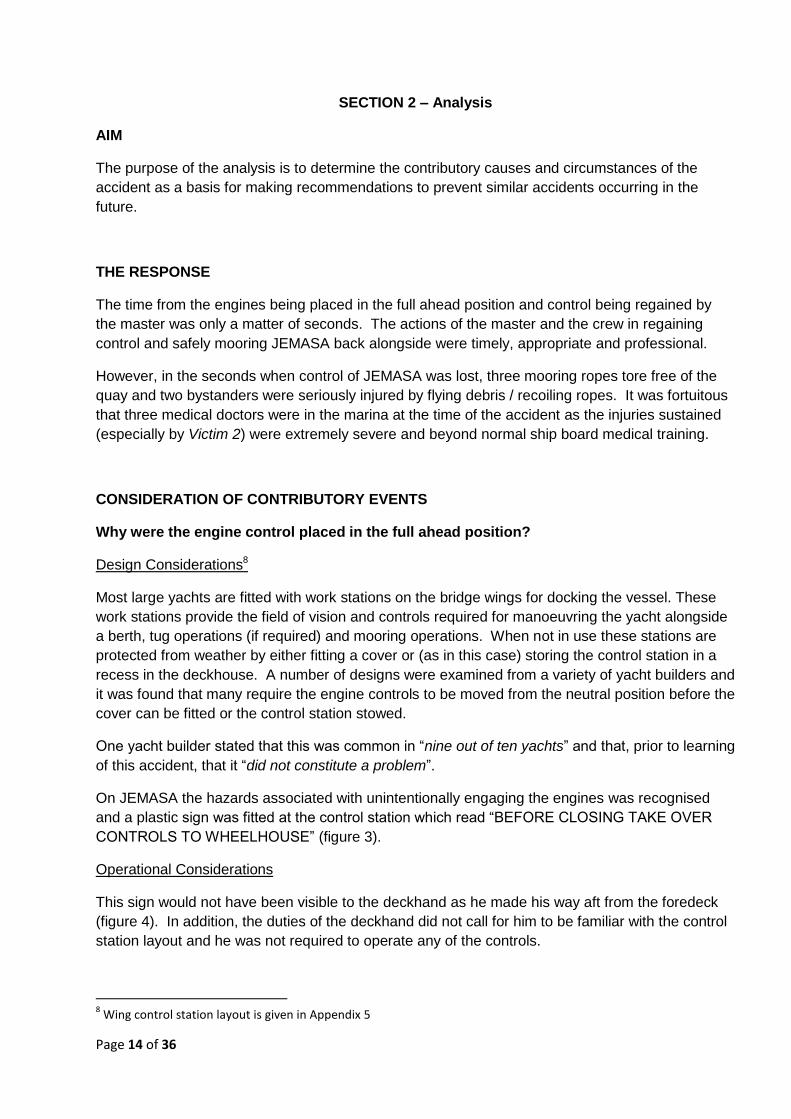
3. Moored directly to the steel piles that anchor the floating quay.
Figure 9: Steel Pile used for mooring.
Appendix 2 shows the mooring arrangement on JEMASA prior to the accident. When JEMASA
moved forward three of the mooring ropes were put in tension and one was made slack.
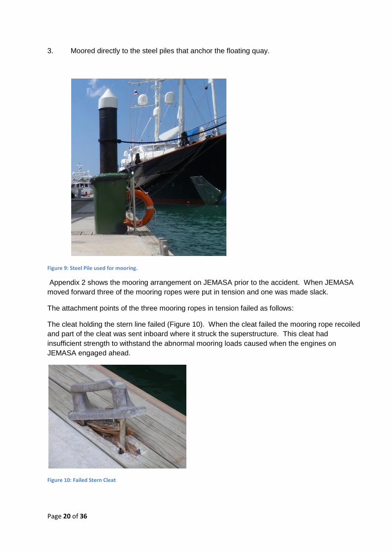
The attachment points of the three mooring ropes in tension failed as follows:
The cleat holding the stern line failed (Figure 10). When the cleat failed the mooring rope recoiled
and part of the cleat was sent inboard where it struck the superstructure. This cleat had
insufficient strength to withstand the abnormal mooring loads caused when the engines on
JEMASA engaged ahead.
Figure 10: Failed Stern Cleat

Page 21 of 36
The cleat holding the head line failed (figure 11), causing the mooring rope to recoil. This cleat
also had insufficient strength to withstand the abnormal mooring loads caused when the engines
on JEMASA engaged ahead.
Figure 11: Failed headline cleat
The mounting of the bollard holding the forward back spring failed and the entire bollard
arrangement became detached from the quay (figure 12). When the mooring rope recoiled, it
brought with it the bollard which was still attached and sent wood debris flying up the quay. It is
believed that it is this debris and recoiling mooring rope which struck the two victims.
Figure 12: Bollard pulled from quay
The failure mode of the bollards differed from the failure of the cleats in that the bollard themselves
had sufficient strength to cope with the loads, but its attachment to the quay did not. Normally
these bollards are mounted between two adjacent concrete pontoons and are held in place by two
rods running through the entire thickness of the pontoons. The bollard that failed was mounted
between one pontoon block and one of the spaces between pontoons for the steel piles and utility

Page 22 of 36
stations. This bollard was held in place by a single rod running through the pontoon block and a
bolt connected to a backing plate behind the soft wood wales.
When the load on this bollard was increased and the soft wood wales failed, it placed a torque
reaction centred on the single through pontoon rod. In turn, this rod failed and the bollard was
freed from the quay.
Figure 13: Bollard mounted through two concrete pontoons
Figure 14: Failed bollard mounting through one concrete pontoon and one backing plate.

Page 23 of 36
It was stated that the cleats were used primarily for “tying up” and mooring ropes are then
transferred to more substantial anchor points (bollards or directly to piles) once the yacht is safely
berthed. This practice should be discouraged as exceptional mooring loads are much more likely
to be generated during mooring and unmooring than when a vessel is laying alongside.
Why were people not involved in the mooring operation struck by the recoiling mooring
ropes / flying debris?
When JEMASA was mooring there were a comparatively large number of persons either transiting
the quay or observing JEMASA berthing who were not playing an active part in mooring
operations. Such persons included the crew of other yachts, the marina manager and assistant
manager, shipping agents for JEMASA, shore workers (including Victim 1) and general spectators
(including Victim 2). Mooring operations are potentially dangerous situations where large amounts
of stored energy can be instantaneously released when equipment fails, as was the case with this
accident.
The amount of stored energy and the potential consequences of its uncontrolled release increase
with vessel size. JEMASA was on the very limit of the design guidelines for the marina at 49.99m
in length. As Yacht Haven Marina has grown to accommodate ever larger yachts, no restrictions
have been put in place to restrict access to the immediate vicinity of mooring operations.
FATIGUE
Fatigue has been shown to be a contributory factor in many accidents. Chapter VIII of the Code to
the STCW Convention requires that all persons should be fit for duty, such that:
1. All persons who are assigned duty as officer in charge of a watch or as a rating
forming part of a watch shall be provided a minimum of 10 hours of rest in any 24 hour
period.
2. The hours of rest may be divided into no more than two periods, one of which shall
be at least 6 hours in length.
3. The requirements for rest periods laid down in paragraphs 1 and 2 need not be
maintained in the case of an emergency or drill or other overriding operational conditions.
4. Notwithstanding the provisions of paragraphs 1 and 2, the minimum period of ten
hours may be reduced to not less than 6 consecutive hours provided that any such
reduction shall not extend beyond two days and not less than 70 hours of rest are provided
each seven day period.
5. Administrations shall require that watch schedules be posted where they are easily
accessible.
The hours of work and rest of the crew onboard JEMASA for the period leading up to the accident
were examined and found to comply with the STCW requirements. There is no indication that
fatigue on the part of any of JEMASA’s crew was contributory factor in the cause of the accident.

Page 24 of 36

Page 25 of 36
SECTION 3 – Conclusions
SAFETY ISSUES DIRECTLY CONTRIBUTING TO THE ACCIDENT
As with most accidents, it is not possible to cite a single event or action as the “cause”. Rather a
sequence of events and circumstances ultimately led to the accident occurring.
1. The design of the wing control station introduced an unnecessary risk into mooring and
unmooring operations by requiring the engine controls to be placed in the full ahead
position before the control station could be closed.
2 The fitting of the plastic warning sign on the control station proved insufficient to ensure that
control was transferred to the bridge before the engine controls were placed full ahead and
the control station closed.
3. Failure to follow SMS Section 9.6 of the safety management system onboard contributed to
a lack of proper procedural control over mooring activities, despite such activities being
identified as potentially dangerous in SMS section 2.3.1.
4. A lack of familiarity with the operation and function of the wing control station controls led
the deckhand to believe the station was disconnected when it was still in control of the
engines.
5. The shore side mooring equipment and its attachment to the quay lacked sufficient strength
to handle the increased mooring loads generated when JEMASA moved ahead.
6. The lack of access restrictions to the quayside during mooring operations led to two
persons not involved in the mooring of JEMASA being struck be recoiling mooring ropes /
flying debris.

Page 26 of 36
SECTION 4 – Recommendations and Actions Taken
001/2010 Wilson Yacht Management are recommended to:
i. Ensure that all risk assessments required by the SMS are carried out,
properly documented and Safe Systems of Work are developed and implemented
onboard all managed yachts.
ii. Provide training in conducting risk assessments to masters and crew
onboard managed yachts, as required.
iii. Make such modifications as may be required onboard managed yachts to
remove, reduce or mitigate any risk of inadvertently engaging engines when closing
bridge wing controls.
002/2010 The Cayman Islands Shipping Registry are recommended to:
i. Inspect wing control station covers as part of routine yacht surveys and
bring any potentially hazardous arrangements to the attention of masters for
rectification.
ii. Ensure that safety management systems are fully implemented, especially
in relation to risk assessments and development of safe systems of work, at all
levels in the organization prior to the issue of any full term Safety Management
Certificate.
003/2010 Yacht Haven Marina are recommended to:
i. Consider both the normal mooring loads and exceptional mooring loads
associated with emergency situations generated by the largest “design yacht” when
selecting and attaching mooring hardware.
ii. Consider introducing controls to the immediate area where mooring
operations are taking place to limit access to those actively involved in the mooring
operation.

Page 27 of 36
ACTIONS TAKEN
During and subsequent to this investigation the following actions have been taken aimed at
preventing a similar accident occurring in the future.
Wilson Yacht Management has introduced a standard companywide Risk Assessment
Methodology which is now in use onboard all managed yachts. As a result, safe systems of work
are being developed. As a result generic checklist and procedures in the Safety Management
System are being made “yacht specific”.
Training in the conduct and documenting of risk assessments is being delivered to masters and
crews of managed yachts as part of the routine superintendent / DP visits onboard. All other
managed yachts have been confirmed as having a wing control station layout that does not
introduce similar risks of inadvertently engaging engines when securing the control station.
Onboard JEMASA, modifications have been made such that it is no longer necessary to move the
engine controls from the neutral position in order to stow the wing control stations, as shown
below:
In addition and as part of the master’s standing orders, an engineer or senior deck officer must
remain in the wheel house or at the wing station controls to prevent unintended operation of the
engine controls during manoeuvring or transfer of command to or from the wing stations.
The status of the wing station controls now forms part of the routine documented checks to be
carried out prior to entering or leaving port.
Yacht Haven Marina has now introduced access control measures to docks and quays when
large or powerful motor yachts are manoeuvring alongside. In such cases access to quays is
restricted to trained marina staff who handle the lines of the manoeuvring yachts.
When large yachts are mooring, care is taken to ensure that the quayside is free of any
unnecessary obstructions such as stores trolleys and bicycles. Additional “bollard type” moorings
have been installed and the “cleat type” mooring points are only used for small yachts and boats.

Page 28 of 36
The Cayman Islands Shipping Registry has issued a Safety Flyer of all registered vessels,
highlighting the hazardous associated with mooring in general and the particular circumstances
surrounding this accident. The flyer (See Appendix 4) was circulated to the Designated Persons of
all companies holding a Document of Compliance issued on behalf of the Cayman Islands.
Inspection of the closure or cover arrangements for bridge wing control stations is now a routine
part of surveys carried out on yachts by CISR surveyors. In addition, similar arrangements to
those present on JEMASA have been identified during the construction of a number of new
yachts. This has led to several design changes being made prior to the yacht’s completion and
delivery.
A revised and updated comprehensive set of instructions for the guidance of surveyors and
auditors is currently under development.

Page 29 of 36
Appendices
Appendix 1: “Yacht Haven Marina”
Appendix 2: Mooring arrangements and subsequent damage
Appendix 3: SURI; support craft to JEMASA
Appendix 4: Flyer to the Large Yacht Industry
Appendix 5: Wing Station Layout

Appendix 1: “Yacht Haven Marina”
Page 30 of 36
YACHT HAVEN MARINA
Figure 15: Arial photo of Yacht Haven Marina (C) SKYCAM
Figure 16: Approaches to Yacht Haven Marina (c) YHM

Appendix 2: Mooring arrangements and subsequent damage.
Page 31 of 36
MOORING ARRANGEMENTS
At the time of the accident, JEMASA had four mooring lines secured to the quay as represented in
the above diagram. When JEMASA moved ahead, lines 1, 2 and 4 pulled from the quay. All
mooring ropes were Nylon Double Braid ropes of 56mm nominal diameter and with a minimum
tensile strength of 805.1 kN.
Figure 18: Typical Cleat Fracture
Figure 19: Bollard Walles Failure
Figure 17: Nylon Double Braid Ropes

Appendix 2: Mooring arrangements and subsequent damage.
Page 32 of 36
Figure 20: Damage to quayside
Figure 21: Recovered mooring bollard

Appendix 3: SURI, support craft to JEMASA.
Page 33 of 36
SURI
Information Copyright © CharterWorld Limited
Figure 23: SURI; JEMASA support craft

Appendix 4: Flyer to the Large Yacht Industry.
Page 34 of 36
CAYMAN ISLANDS SHIPPING REGISTRY Maritime Authority of the Cayman Islands
FLYER TO THE LARGE YACHT INDUSTRY
Fatal accident during mooring operations.
A large yacht (600 GT, 50m LOA) was berthing at a marina in
South East Asia. Wind and tidal conditions were benign and
the arrival and mooring procedures followed the yacht’s
normal routine. During the mooring operation the yacht was
being manoeuvred from the port bridge wing control station.
When not in use, this station folds into the bridge house for
storage.
Due to the design of the bridge wing control station it is
essential that the controls are deactivated prior to closing the
station. It is necessary to put the engine controls in the “full
ahead” position before the control station can be closed.
After the yacht had completed mooring, with four lines ashore, a crew member placed the bridge wing controls in
the “full ahead” position and closed the control station. When the control station was closed, the yachts engines
were running with control still at the port bridge wing station.
The engines engaged, the yacht proceeded to move ahead and the yacht broke free of its moorings. No mooring
ropes parted but three of the mooring points in use on the quay failed. When the moorings failed, two bystanders
on the quay were struck by flying debris and / or recoiling
mooring ropes. One person was hit on the legs which were
fractured. The other person was struck on the head and
sustained serious injuries.
Both were evacuated to hospital. The person struck on the legs
underwent reconstructive surgery and is expected to make a
full recovery. The person struck on the head remained in a
critical condition and died five days later.
After the moorings failed, manoeuvring control was taken by the main bridge manoeuvring station and the yacht
quickly brought under control. The yacht was then safely moored back alongside the quay.
Safety Issues

Appendix 4: Flyer to the Large Yacht Industry.
Page 35 of 36
The risks in conducting mooring operations must be rigorously assessed and safe working practices developed. Each vessel should have a set of guidelines for achieving a safe mooring which can be modified to suit operational or environmental circumstances.
Where novel or unusual designs introduce additional risks, these should be properly assessed and appropriate control measures introduced. Removal or elimination of such risks should be considered in preference to introducing procedural controls aimed at reducing or mitigating the risks.
When choosing suitable mooring points ashore for the vessel (bollards, cleats, etc), both the normal mooring loads and exceptional loads associated with emergency situations should be considered.
Mooring operations are potentially dangerous situations where large amounts of stored energy can be instantaneously released if mooring equipment fails. This can result in serious injury and death. Persons not involved in the mooring operation should be kept at a safe distance until the operation is complete.
Detailed information and guidance on mooring operations is available in publications produced by the Nautical Institute, the UK Maritime and Coastguard Agency (MCA) and the Oil Companies International Marine Forum (OCIMF).
NOTE
This document, containing urgent safety information, has been produced for marine safety purposes only, on the
basis of information available to date. The sole objective of the investigation of any accident which is conducted
under the Cayman Islands Merchant Shipping Law (2008 Revision) is the prevention of future accidents through the
ascertainment of its causes and circumstances. It is not the purpose of an investigation to determine liability or,
except as it is necessary to achieve its objective, to apportion blame.
The Cayman Islands Shipping Registry (CISR) is carrying out an investigation into this accident. The CISR will publish a
full report on completion of the investigation. The report will be available from www.cishipping.com.
28 February 2009

Appendix 5: Wing Station Layout
Page 36 of 36