Embed Size (px)
Citation preview
REPORT OFSUBSURFACEINVESTIGATIONANDGEOTECHNICALENGINEERINGSERVICES
Towne South Church AdditionElizabeth City, North Carolina
G E T Project No: EC14-188GMay 30, 2014
PREPARED FOR:
106 Capital Trace, Unit E Elizabeth City, North Carolina 27909Phone: (252)-335-9765
www.getsolutionsinc.com
May 30, 2014
TO: Towne South Church of Christ2224 Peartree RoadElizabeth City, NC 27909
Attn: Mr. David Brothers
RE: Report of Subsurface Investigation and Geotechnical Engineering ServicesTowne South Church AdditionElizabeth City, North CarolinaGET Project No: EC14-188G
Dear Mr. Brothers:
In compliance with your instructions, we have completed our Subsurface Investigation andGeotechnical Engineering Services for the above referenced project. The results of thisstudy, together with our recommendations, are presented in this report.
Often, because of design and construction details that occur on a project, questions ariseconcerning subsurface conditions. G E T Solutions, Inc. would be pleased to continue itsrole as Geotechnical Engineer during the project implementation.
Thank you for the opportunity to work with you on this project. We trust that theinformation contained herein meets your immediate need, and should you have anyquestions or if we could be of further assistance, please do not hesitate to contact us.
Respectfully Submitted,G E T Solutions, Inc.
Gerald W. Stalls Jr., P.E.Senior Project EngineerNC Reg. # 034336
Camille A. Kattan, P.E.Principal EngineerNC Reg. # 014103
Copies: (1) Client
106 Capital Trace Unit E Elizabeth City, NC 27909 Phone: (252)335-9765 Fax: (252)[email protected]
TABLE OF CONTENTS page 1 of 1
EXECUTIVE SUMMARY ......................................................................................................... i
1.0 PROJECT INFORMATION ......................................................................................... 1
1.1 Project Authorization ....................................................................................... 11.2 Project Description .......................................................................................... 11.3 Purpose and Scope of Services....................................................................... 2
2.0 FIELD AND LABORATORY PROCEDURES .............................................................. 3
2.1 Field Exploration.............................................................................................. 32.2 Laboratory Testing .......................................................................................... 4
3.0 SITE AND SUBSURFACE CONDITIONS.................................................................... 5
3.1 Site Location and Description .......................................................................... 53.2 Subsurface Soil Conditions.............................................................................. 53.3 Groundwater Information................................................................................. 6
4.0 EVALUATION AND RECOMMENDATIONS................................................................ 7
4.1 Clearing and Grading ...................................................................................... 74.2 Subgrade Preparation ..................................................................................... 84.3 Structural Fill and Placement........................................................................... 94.4 Suitability of On-Site Soils ............................................................................... 94.5 Shallow Foundation Design Recommendations ............................................. 104.6 Shallow Foundation Excavations ................................................................... 104.7 Shallow Foundation Settlements ................................................................... 114.8 Floor Slabs.................................................................................................... 124.9 Seismic Site Evaluation................................................................................. 12
5.0 CONSTRUCTION CONSIDERATIONS..................................................................... 12
5.1 Drainage and Groundwater Concerns............................................................ 125.2 Site Utility Installation .................................................................................... 135.3 Excavations................................................................................................... 13
6.0 REPORT LIMITATIONS ........................................................................................... 14
APPENDIX I BORING LOCATION PLANAPPENDIX II BORING LOGSAPPENDIX III GENERALIZED SOIL PROFILEAPPENDIX IV CLASSIFICATION SYSTEM FOR SOIL EXPLORATION
Report of Subsurface Investigation and Geotechnical Engineering Services May 30, 2014Towne South Church AdditionElizabeth City, North CarolinaGET Project No: EC14-188G
1
1.0 PROJECT INFORMATION
1.1 Project Authorization
G E T Solutions, Inc. has completed our Geotechnical Engineering study for the proposedTowne South Church Addition project. The Geotechnical Engineering Services wereconducted in general accordance with G E T Solutions, Inc. Proposal No. PEC14-151G,dated March 31, 2014. The authorization to proceed with the services was received in theform of the work authorization form signed by Mr. David Brothers with Towne South Churchof Christ on the date of April 25, 2014.
1.2 Project Description
The proposed construction at this site is planned to consist of building a new single storyaddition to the existing church. The existing church structure has been reported to consistof a pre-engineered metal frame building supported by a monolithic slab on grade withperimeter turn down foundations. Additionally, it has been reported that the existingstructure has not experienced any noticeable settlement. The addition will have a footprint area of about 7,200 square feet and will be of pre-engineered metal frame and metalstud design supported by shallow foundations with a slab on grade. The proposedfinished floor elevation (FFE) of the structure is anticipated to coincide with the FFE of theexisting structure, which was reported on the project site plan to be 12.2 feet MSL. Theexisting site grade elevations within the proposed addition area were generally noted torange from about 10.4 to 11.5 feet MSL. As such, it is anticipated that the fill operationsnecessary to establish the design grade elevations will generally range from about 4 to 18inches.
The maximum foundation loading conditions associated with the structure were noted byNRW Engineering to be on the order of 41 kips. Furthermore, the foundation design wasgoverned by uplift with the maximum soil contact pressure generally on the order of about500 psf and not expected to exceed about 750 psf. As indicated on the project foundationplans, a presumed bearing capacity of 2000 psf was used to determine that the columnspread footings will have a foot print area ranging from 4 feet square to 9 feet square withembedment depths ranging from about 3’-4” to 4’ below the proposed finished floorelevation. These embedment depths correspond to elevations generally ranging from 8.8feet MSL to 8.1 feet MSL, respectively.
The development will also include the paving of the existing gravel parking lot and theconstruction of a new asphalt paved parking lot to the west of the building expansion.However, at this time our investigation did not include the proposed parking lotconstruction areas.
Report of Subsurface Investigation and Geotechnical Engineering Services May 30, 2014Towne South Church AdditionElizabeth City, North CarolinaGET Project No: EC14-188G
2
If any of the noted information is incorrect or has changed, please inform G E TSolutions, Inc. so that we may amend the recommendations presented in this report,if appropriate.
1.3 Purpose and Scope of Services
The purpose of this study was to obtain information on the general subsurface conditionsat the proposed project site within the vicinity of the building addition. The subsurfaceconditions encountered were then evaluated with respect to the available projectcharacteristics. In this regard, engineering assessments for the following items wereformulated:
1. General assessment of the soils revealed by the borings performed at theproposed development.
2. General location and description of potentially deleterious materialencountered in the borings that may interfere with construction progress orstructure performance, including existing fills or surficial/subsurfaceorganics.
3. Soil subgrade preparation, including stripping, grading and compaction.Engineering criteria for placement and compaction of approved structural fillmaterial.
4. Construction considerations for fill placement, subgrade preparation, andfoundation excavations.
5. Feasibility of utilizing a shallow foundation system for support of theproposed structure. Design parameters required for the foundation systems,including foundation sizes, allowable bearing pressures, foundation levelsand expected total and differential settlements.
6. Seismic site classification provided based on the results of the StandardPenetration Test (SPT) borings performed at the project site as well as ourexperience in the project area.
The scope of services did not include an environmental assessment for determining thepresence or absence of wetlands or hazardous or toxic material in the soil, bedrock,surface water, groundwater or air, on or below or around this site. Prior to development ofthis site, an environmental assessment is advisable.
Report of Subsurface Investigation and Geotechnical Engineering Services May 30, 2014Towne South Church AdditionElizabeth City, North CarolinaGET Project No: EC14-188G
3
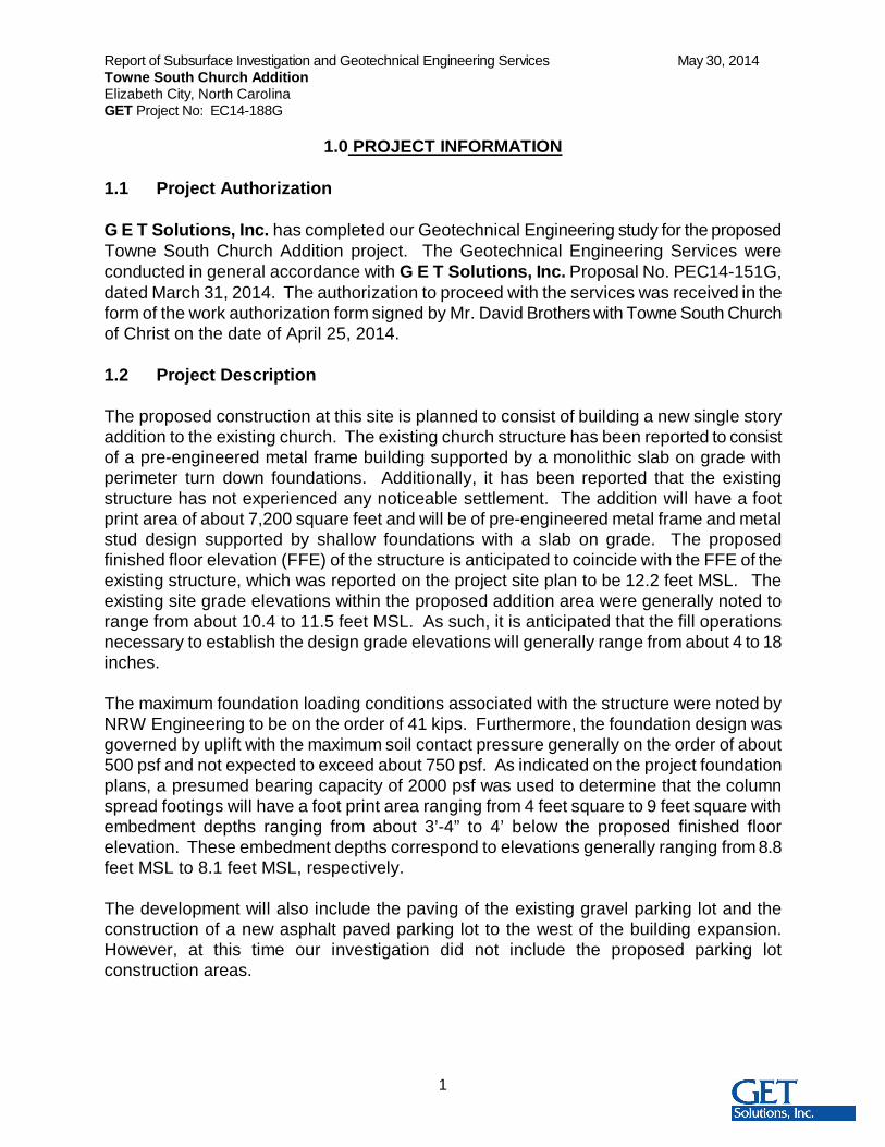
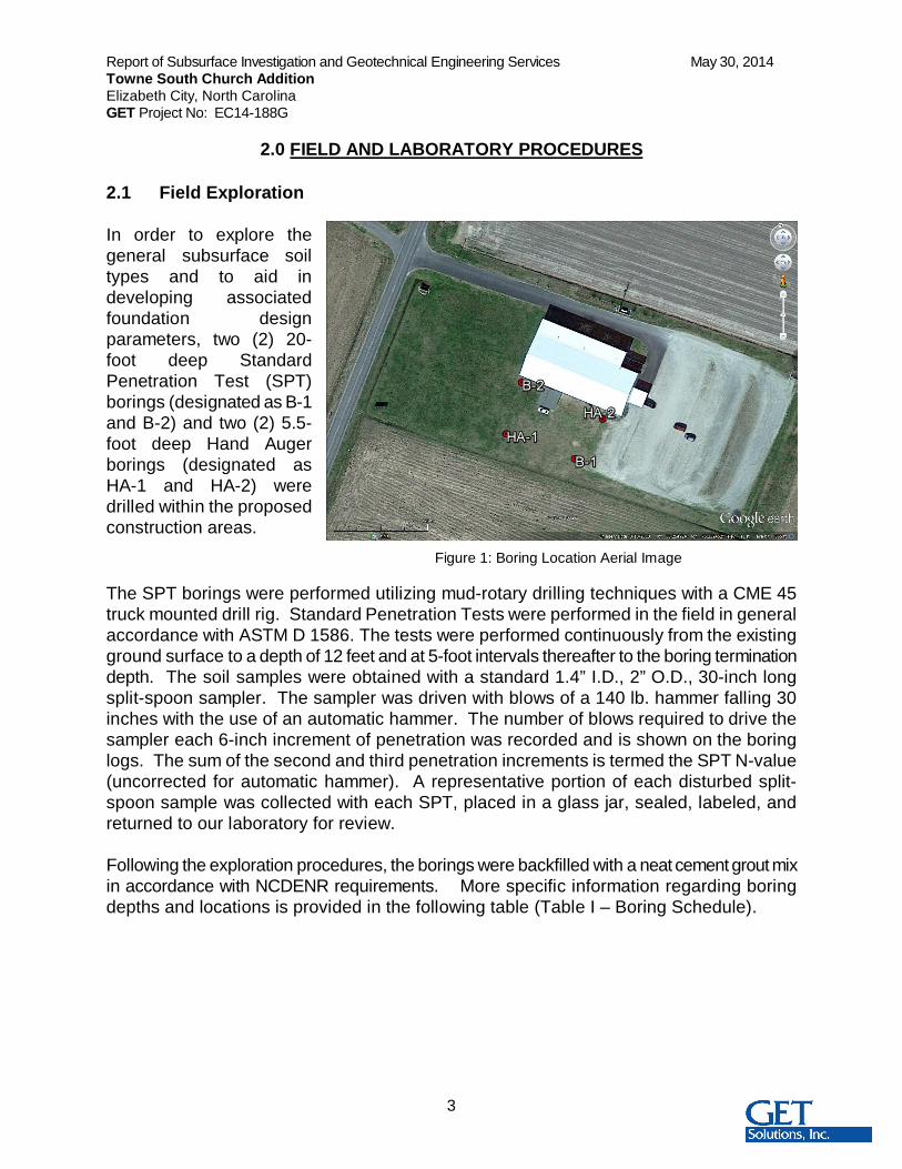
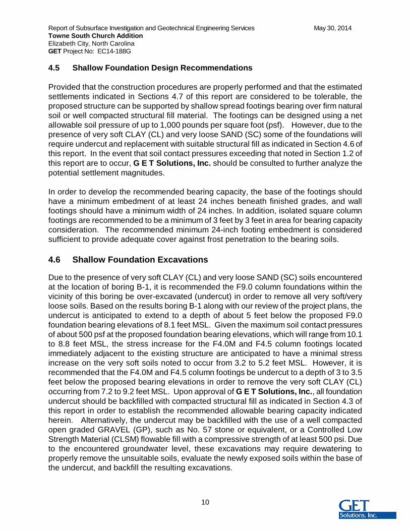
Figure 1: Boring Location Aerial Image
2.0 FIELD AND LABORATORY PROCEDURES
2.1 Field Exploration
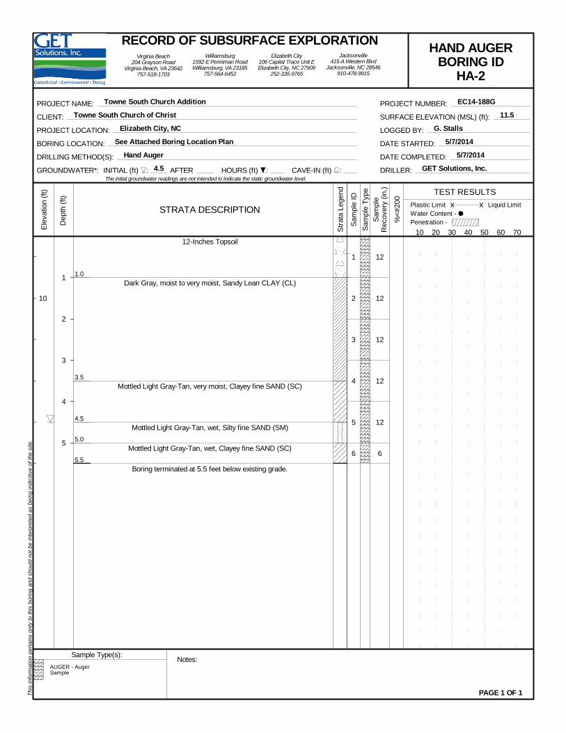
In order to explore thegeneral subsurface soiltypes and to aid indeveloping associatedfoundation designparameters, two (2) 20-foot deep StandardPenetration Test (SPT)borings (designated as B-1and B-2) and two (2) 5.5-foot deep Hand Augerborings (designated asHA-1 and HA-2) weredrilled within the proposedconstruction areas.
The SPT borings were performed utilizing mud-rotary drilling techniques with a CME 45truck mounted drill rig. Standard Penetration Tests were performed in the field in generalaccordance with ASTM D 1586. The tests were performed continuously from the existingground surface to a depth of 12 feet and at 5-foot intervals thereafter to the boring terminationdepth. The soil samples were obtained with a standard 1.4” I.D., 2” O.D., 30-inch longsplit-spoon sampler. The sampler was driven with blows of a 140 lb. hammer falling 30inches with the use of an automatic hammer. The number of blows required to drive thesampler each 6-inch increment of penetration was recorded and is shown on the boringlogs. The sum of the second and third penetration increments is termed the SPT N-value(uncorrected for automatic hammer). A representative portion of each disturbed split-spoon sample was collected with each SPT, placed in a glass jar, sealed, labeled, andreturned to our laboratory for review.
Following the exploration procedures, the borings were backfilled with a neat cement grout mixin accordance with NCDENR requirements. More specific information regarding boringdepths and locations is provided in the following table (Table I – Boring Schedule).
Report of Subsurface Investigation and Geotechnical Engineering Services May 30, 2014Towne South Church AdditionElizabeth City, North CarolinaGET Project No: EC14-188G
4
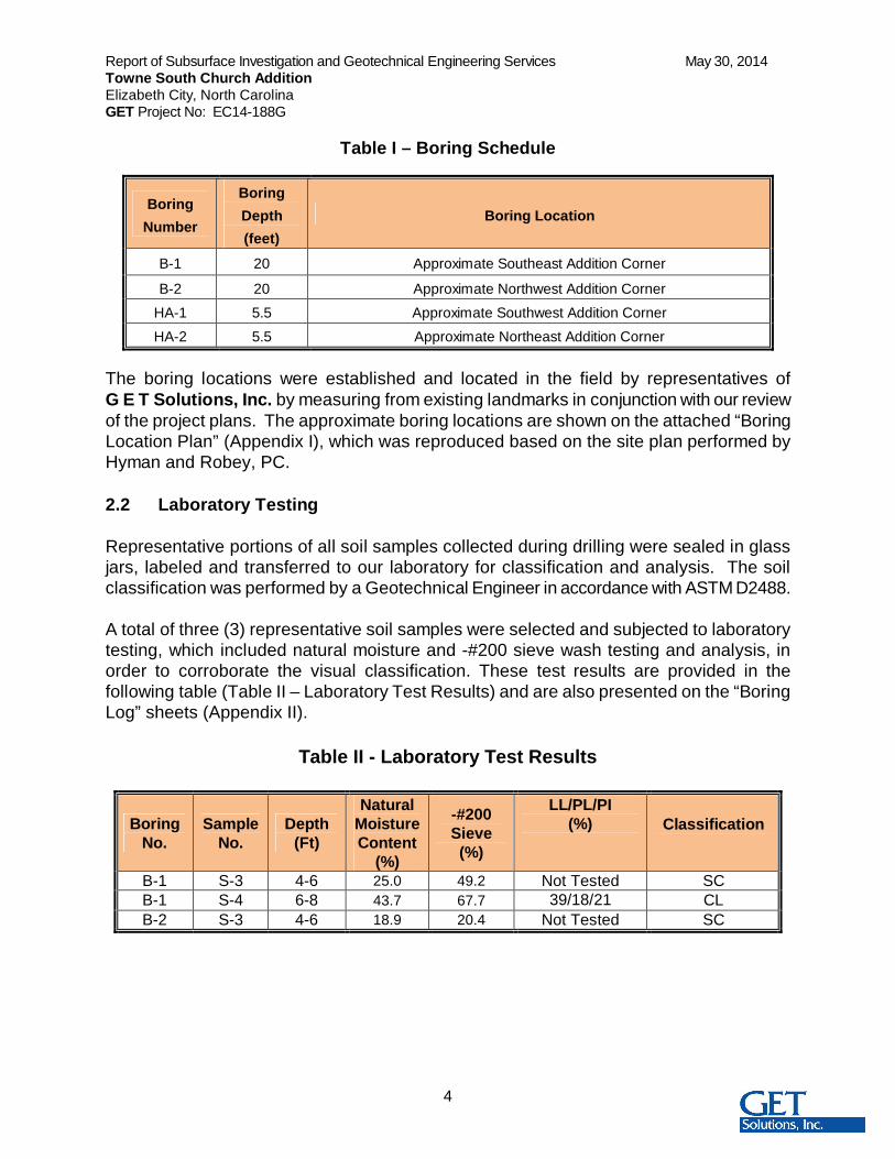
Table I – Boring Schedule
BoringNumber
BoringDepth(feet)
Boring Location
B-1 20 Approximate Southeast Addition Corner
B-2 20 Approximate Northwest Addition CornerHA-1 5.5 Approximate Southwest Addition CornerHA-2 5.5 Approximate Northeast Addition Corner
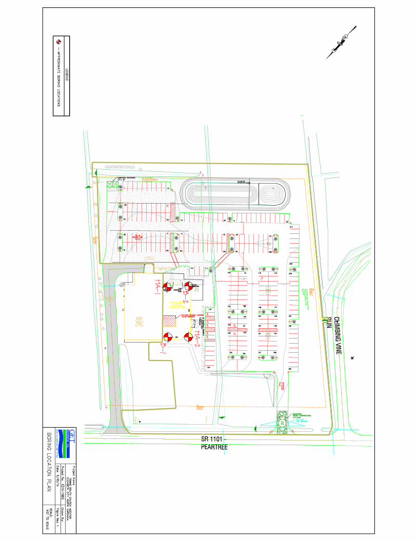
The boring locations were established and located in the field by representatives ofG E T Solutions, Inc. by measuring from existing landmarks in conjunction with our reviewof the project plans. The approximate boring locations are shown on the attached “BoringLocation Plan” (Appendix I), which was reproduced based on the site plan performed byHyman and Robey, PC.
2.2 Laboratory Testing
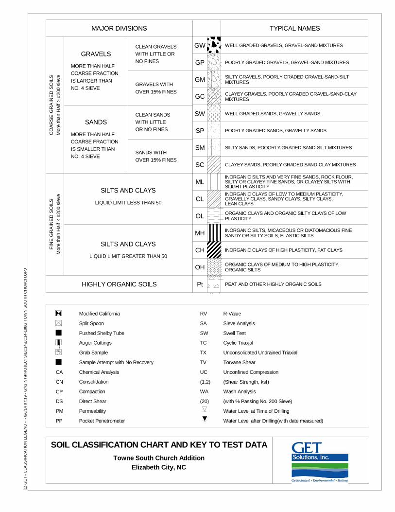
Representative portions of all soil samples collected during drilling were sealed in glassjars, labeled and transferred to our laboratory for classification and analysis. The soilclassification was performed by a Geotechnical Engineer in accordance with ASTM D2488.
A total of three (3) representative soil samples were selected and subjected to laboratorytesting, which included natural moisture and -#200 sieve wash testing and analysis, inorder to corroborate the visual classification. These test results are provided in thefollowing table (Table II – Laboratory Test Results) and are also presented on the “BoringLog” sheets (Appendix II).
Table II - Laboratory Test Results
BoringNo.
SampleNo.
Depth(Ft)
NaturalMoistureContent
(%)
-#200Sieve(%)
LL/PL/PI(%) Classification
B-1 S-3 4-6 25.0 49.2 Not Tested SCB-1 S-4 6-8 43.7 67.7 39/18/21 CLB-2 S-3 4-6 18.9 20.4 Not Tested SC
Report of Subsurface Investigation and Geotechnical Engineering Services May 30, 2014Towne South Church AdditionElizabeth City, North CarolinaGET Project No: EC14-188G
5
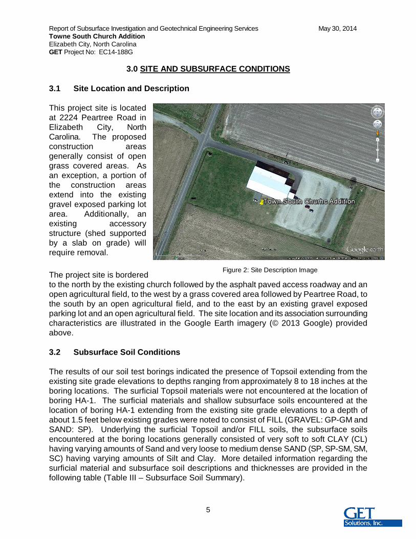
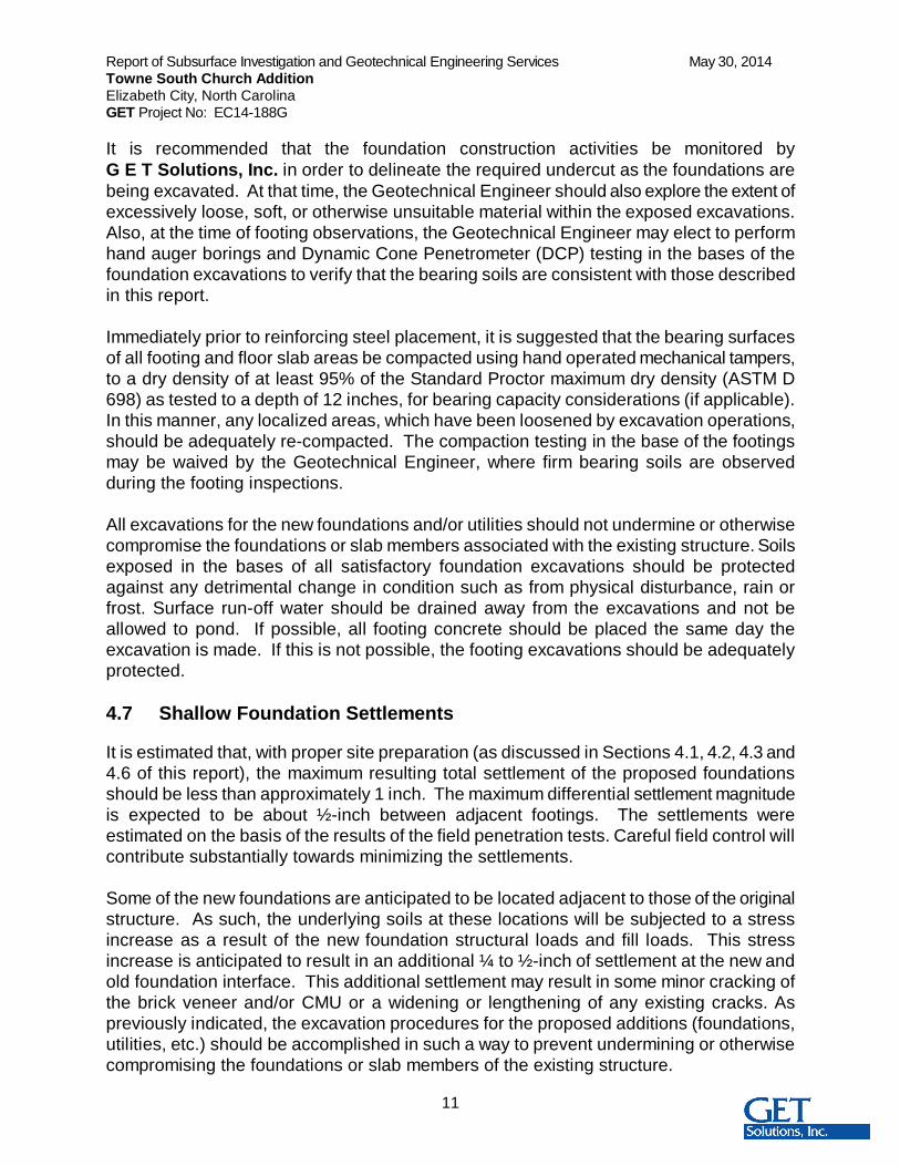
Figure 2: Site Description Image
3.0 SITE AND SUBSURFACE CONDITIONS
3.1 Site Location and Description
This project site is locatedat 2224 Peartree Road inElizabeth City, NorthCarolina. The proposedconstruction areasgenerally consist of opengrass covered areas. Asan exception, a portion ofthe construction areasextend into the existinggravel exposed parking lotarea. Additionally, anexisting accessorystructure (shed supportedby a slab on grade) willrequire removal.
The project site is borderedto the north by the existing church followed by the asphalt paved access roadway and anopen agricultural field, to the west by a grass covered area followed by Peartree Road, tothe south by an open agricultural field, and to the east by an existing gravel exposedparking lot and an open agricultural field. The site location and its association surroundingcharacteristics are illustrated in the Google Earth imagery (© 2013 Google) providedabove.
3.2 Subsurface Soil Conditions
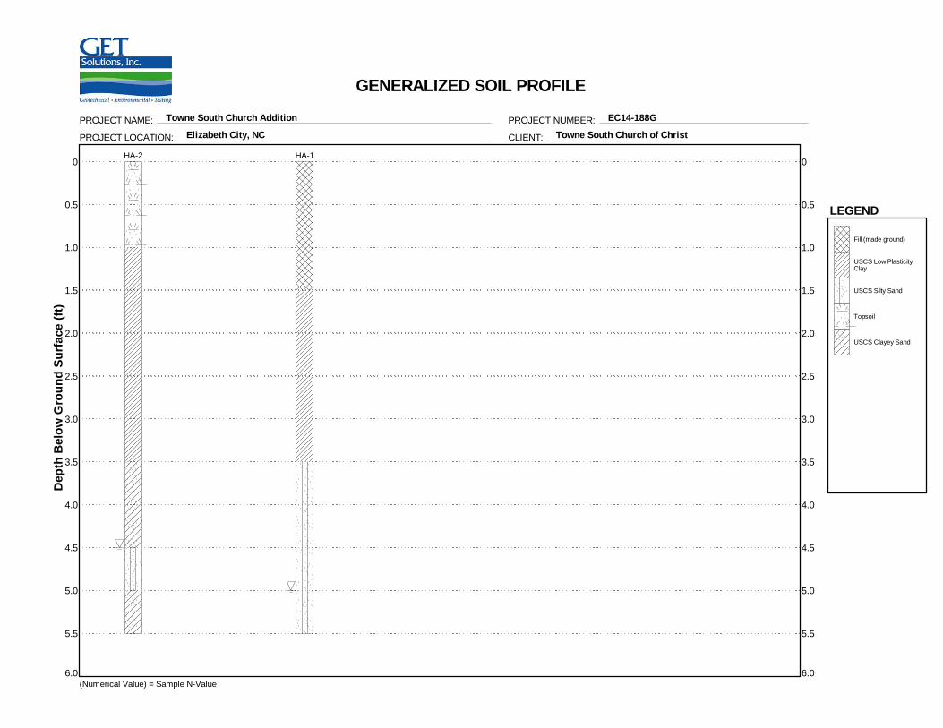
The results of our soil test borings indicated the presence of Topsoil extending from theexisting site grade elevations to depths ranging from approximately 8 to 18 inches at theboring locations. The surficial Topsoil materials were not encountered at the location ofboring HA-1. The surficial materials and shallow subsurface soils encountered at thelocation of boring HA-1 extending from the existing site grade elevations to a depth ofabout 1.5 feet below existing grades were noted to consist of FILL (GRAVEL: GP-GM andSAND: SP). Underlying the surficial Topsoil and/or FILL soils, the subsurface soilsencountered at the boring locations generally consisted of very soft to soft CLAY (CL)having varying amounts of Sand and very loose to medium dense SAND (SP, SP-SM, SM,SC) having varying amounts of Silt and Clay. More detailed information regarding thesurficial material and subsurface soil descriptions and thicknesses are provided in thefollowing table (Table III – Subsurface Soil Summary).
Report of Subsurface Investigation and Geotechnical Engineering Services May 30, 2014Towne South Church AdditionElizabeth City, North CarolinaGET Project No: EC14-188G
6
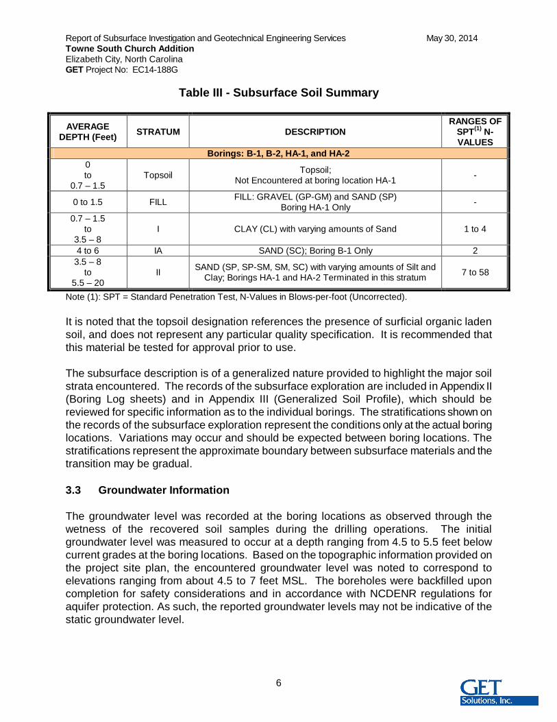
Table III - Subsurface Soil Summary
AVERAGEDEPTH (Feet) STRATUM DESCRIPTION
RANGES OFSPT(1) N-VALUES
Borings: B-1, B-2, HA-1, and HA-20to
0.7 – 1.5Topsoil Topsoil;
Not Encountered at boring location HA-1 -
0 to 1.5 FILL FILL: GRAVEL (GP-GM) and SAND (SP)Boring HA-1 Only -
0.7 – 1.5to
3.5 – 8I CLAY (CL) with varying amounts of Sand 1 to 4
4 to 6 IA SAND (SC); Boring B-1 Only 23.5 – 8
to5.5 – 20
II SAND (SP, SP-SM, SM, SC) with varying amounts of Silt andClay; Borings HA-1 and HA-2 Terminated in this stratum 7 to 58
Note (1): SPT = Standard Penetration Test, N-Values in Blows-per-foot (Uncorrected).
It is noted that the topsoil designation references the presence of surficial organic ladensoil, and does not represent any particular quality specification. It is recommended thatthis material be tested for approval prior to use.
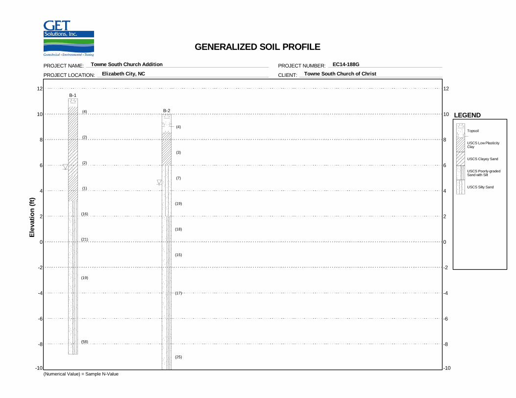
The subsurface description is of a generalized nature provided to highlight the major soilstrata encountered. The records of the subsurface exploration are included in Appendix II(Boring Log sheets) and in Appendix III (Generalized Soil Profile), which should bereviewed for specific information as to the individual borings. The stratifications shown onthe records of the subsurface exploration represent the conditions only at the actual boringlocations. Variations may occur and should be expected between boring locations. Thestratifications represent the approximate boundary between subsurface materials and thetransition may be gradual.
3.3 Groundwater Information
The groundwater level was recorded at the boring locations as observed through thewetness of the recovered soil samples during the drilling operations. The initialgroundwater level was measured to occur at a depth ranging from 4.5 to 5.5 feet belowcurrent grades at the boring locations. Based on the topographic information provided onthe project site plan, the encountered groundwater level was noted to correspond toelevations ranging from about 4.5 to 7 feet MSL. The boreholes were backfilled uponcompletion for safety considerations and in accordance with NCDENR regulations foraquifer protection. As such, the reported groundwater levels may not be indicative of thestatic groundwater level.
Report of Subsurface Investigation and Geotechnical Engineering Services May 30, 2014Towne South Church AdditionElizabeth City, North CarolinaGET Project No: EC14-188G
7
A potential for perched water conditions to occur near and/or slightly below the existingsurface elevations at this site is likely due to the presence of shallow subsurface restrictivesoils including CLAY: CL encountered at the boring locations. These perched waterconditions may occur during the wet season and/or periods of heavy precipitation.
Groundwater conditions will vary with environmental variations and seasonal conditions,such as the frequency and magnitude of rainfall patterns, as well as man-made influences,such as existing swales, drainage ponds, underdrains and areas of covered soil (pavedparking lots, sidewalks, etc.). Seasonal groundwater fluctuations of 3 feet are commonin the project’s area; however, greater fluctuations have been documented. Werecommend that the contractor determine the actual groundwater levels at the time of theconstruction to determine groundwater impact on the construction procedures.
4.0 EVALUATIONS AND RECOMMENDATIONS
Our recommendations are based on the previously discussed project information, ourinterpretation of the soil test borings and laboratory data, and our observations during oursite reconnaissance. If the proposed construction should vary from what was described, werequest the opportunity to review our recommendations and make any necessary changes.
4.1 Clearing and Grading
The proposed construction areas should be cleared as necessary to remove all surficialorganic materials (Topsoil). It is estimated that a cut ranging from about 8 to 18 inches indepth will be required to remove the Topsoil. This cut is expected to extend deeper inisolated areas to remove deposits of organic soils, or unsuitable soils, which becomeevident during the clearing. It is recommended that the clearing operations extend laterallyat least 5 feet beyond the perimeter of the proposed construction areas.
Clean topsoil, where encountered, should be stockpiled for later use in landscaped areas.However, as indicated in Section 3.2 of this report, the topsoil designation noted in theboring logs and in Section 3.2 of this report references the presence of surficial organicladen soil and does not represent any particular quality specification. Accordingly, asdetermined by the Civil Engineer of Record and/or the Owner, these organic ladenmaterials may require testing for approval prior to use.
At this time, the FILL encountered at the location of boring HA-1 is anticipated to besuitable to remain in place provided that it is evaluated to be well compacted and stableduring the subgrade preparation procedures performed by G E T Solutions, Inc. asrecommended in Section 4.2 of this report.
Report of Subsurface Investigation and Geotechnical Engineering Services May 30, 2014Towne South Church AdditionElizabeth City, North CarolinaGET Project No: EC14-188G
8
Following the initial clearing, the resulting exposed subgrade will generally be comprisedof CLAY (CL) containing an appreciable amount of fines. Additionally, based on our fieldobservations the current natural moisture content of the shallow subsurface soils isestimated to be near or above its respective optimum moisture content. Accordingly,combinations of excess surface moisture from precipitation ponding on the site and theconstruction traffic, including heavy compaction equipment, may create pumping andgeneral deterioration of the bearing capabilities of the surface soils. Therefore,undercutting to remove soft soils from within the proposed building areas may be required.
Furthermore, inherently wet subgrade soils combined with potential poor site drainagemake this site particularly susceptible to subgrade deterioration. Thus, grading should beperformed during a dry season, if at all possible. This should minimize these potentialproblems, although they may not be eliminated. The project’s budget should include anallowance for subgrade improvements (undercut and backfill with select fill).
4.2 Subgrade Preparation
Following the clearing operation, the newly exposed subgrade soils should be densifiedwith a large static smooth drum roller and subsequently evaluated by G E T Solutions,Inc. for stability by means of proofrolling to check for pockets of loose material hiddenbeneath a crust of better soil. Several passes should be made by a large rubber-tiredroller or loaded dump truck over the construction areas, with the successive passesaligned perpendicularly. The number of passes will be determined in the field by theGeotechnical Engineer depending on the soil conditions. Any pumping and unstable areasobserved during proofrolling (beyond the initial cut) should be undercut and/or stabilized atthe direction of the Geotechnical Engineer.
As indicated in Section 4.1 of this report, the surficial and shallow subsurface FILL noted tobe comprised of GRAVEL (GP-GM) and SAND (SP) encountered at the location of boringHA-1 is anticipated to be suitable to remain in place. However, the subgrade evaluationprocedures, should include a series of test pit excavations and/or hand auger borings tofurther determine the suitability of the soils to remain in place. The location and depths ofthese additional exploration procedures should be determined in the field duringconstruction by G E T Solutions, Inc.
Following the subgrade evaluations and approval by the engineer, it is recommended thatthe top 12 inches of the newly exposed subgrade soils as well as any FILL allowed toremain in place be compacted to a dry density of at least 95 percent of the StandardProctor maximum dry density (ASTM D 698). In the event that the FILL soils currently inplace are found to be compacted to less than that indicated above, it is likely that they willrequire removal and should be replaced with imported Structural Fill as indicated inSection 4.3 of this report.
Report of Subsurface Investigation and Geotechnical Engineering Services May 30, 2014Towne South Church AdditionElizabeth City, North CarolinaGET Project No: EC14-188G
9
4.3 Structural Fill and Placement
Following the approval of the natural subgrade soils by the Geotechnical Engineer, theplacement of the fill required to establish the design grades may begin. Any material to beused for structural fill should be evaluated and tested by G E T Solutions, Inc. prior toplacement to determine if they are suitable for the intended use. Suitable structural fillmaterial should consist of sand or gravel containing less than 20% by weight of fines (SP,SM, SW, GP, GW), having a liquid limit less than 20 and plastic limit less than 6, andshould be free of rubble, organics, clay, debris and other unsuitable material.
All structural fill should be compacted to a dry density of at least 95 percent of theStandard Proctor maximum dry density (ASTM D 698). In general, the compaction shouldbe accomplished by placing the fill in maximum 10-inch loose lifts and mechanicallycompacting each lift to at least the specified minimum dry density. A representative ofG E T Solutions, Inc. should perform field density tests on each lift as necessary toassure that adequate compaction is achieved.
Backfill material in utility trenches within the construction areas should consist of structuralfill (as previously above), and should be compacted to at least 95 percent of ASTM D 698.This fill should be placed in 4 to 6 inch loose lifts when hand compaction equipment isused.
Care should be used when operating the compactors near existing structures to avoidtransmission of the vibrations that could cause settlement damage or disturb occupants. Inthis regard, it is recommended that the vibratory roller remain at least 25 feet away fromexisting structures; these areas should be compacted with small, hand-operatedcompaction equipment.
4.4 Suitability of On-site Soils
Generally the majority of the shallow subsurface soils encountered at the boring locationsat depths ranging from the existing grades and extending to the depths ranging from about4 to 8 feet (TOPSOIL, CLAY: CL; SAND: SM with Clay, SC) are not anticipated to besuitable for re-use as structural fill. However, provided it is acceptable to the owner and/orCivil Engineer of Record these soils may potentially be used as fill within landscapedareas. As such, this site is anticipated to require imported fill materials for use as filland/or backfill.
Further classification testing (natural moisture content, gradation analysis, and Proctortesting) should be performed during construction to evaluate the suitability of on-siteexcavated soils and/or proposed imported borrow materials for reuse as fill withinstructural areas.
Report of Subsurface Investigation and Geotechnical Engineering Services May 30, 2014Towne South Church AdditionElizabeth City, North CarolinaGET Project No: EC14-188G
10
4.5 Shallow Foundation Design Recommendations
Provided that the construction procedures are properly performed and that the estimatedsettlements indicated in Sections 4.7 of this report are considered to be tolerable, theproposed structure can be supported by shallow spread footings bearing over firm naturalsoil or well compacted structural fill material. The footings can be designed using a netallowable soil pressure of up to 1,000 pounds per square foot (psf). However, due to thepresence of very soft CLAY (CL) and very loose SAND (SC) some of the foundations willrequire undercut and replacement with suitable structural fill as indicated in Section 4.6 ofthis report. In the event that soil contact pressures exceeding that noted in Section 1.2 ofthis report are to occur, G E T Solutions, Inc. should be consulted to further analyze thepotential settlement magnitudes.
In order to develop the recommended bearing capacity, the base of the footings shouldhave a minimum embedment of at least 24 inches beneath finished grades, and wallfootings should have a minimum width of 24 inches. In addition, isolated square columnfootings are recommended to be a minimum of 3 feet by 3 feet in area for bearing capacityconsideration. The recommended minimum 24-inch footing embedment is consideredsufficient to provide adequate cover against frost penetration to the bearing soils.
4.6 Shallow Foundation Excavations
Due to the presence of very soft CLAY (CL) and very loose SAND (SC) soils encounteredat the location of boring B-1, it is recommended the F9.0 column foundations within thevicinity of this boring be over-excavated (undercut) in order to remove all very soft/veryloose soils. Based on the results boring B-1 along with our review of the project plans, theundercut is anticipated to extend to a depth of about 5 feet below the proposed F9.0foundation bearing elevations of 8.1 feet MSL. Given the maximum soil contact pressuresof about 500 psf at the proposed foundation bearing elevations, which will range from 10.1to 8.8 feet MSL, the stress increase for the F4.0M and F4.5 column footings locatedimmediately adjacent to the existing structure are anticipated to have a minimal stressincrease on the very soft soils noted to occur from 3.2 to 5.2 feet MSL. However, it isrecommended that the F4.0M and F4.5 column footings be undercut to a depth of 3 to 3.5feet below the proposed bearing elevations in order to remove the very soft CLAY (CL)occurring from 7.2 to 9.2 feet MSL. Upon approval of G E T Solutions, Inc., all foundationundercut should be backfilled with compacted structural fill as indicated in Section 4.3 ofthis report in order to establish the recommended allowable bearing capacity indicatedherein. Alternatively, the undercut may be backfilled with the use of a well compactedopen graded GRAVEL (GP), such as No. 57 stone or equivalent, or a Controlled LowStrength Material (CLSM) flowable fill with a compressive strength of at least 500 psi. Dueto the encountered groundwater level, these excavations may require dewatering toproperly remove the unsuitable soils, evaluate the newly exposed soils within the base ofthe undercut, and backfill the resulting excavations.
Report of Subsurface Investigation and Geotechnical Engineering Services May 30, 2014Towne South Church AdditionElizabeth City, North CarolinaGET Project No: EC14-188G
11
It is recommended that the foundation construction activities be monitored byG E T Solutions, Inc. in order to delineate the required undercut as the foundations arebeing excavated. At that time, the Geotechnical Engineer should also explore the extent ofexcessively loose, soft, or otherwise unsuitable material within the exposed excavations.Also, at the time of footing observations, the Geotechnical Engineer may elect to performhand auger borings and Dynamic Cone Penetrometer (DCP) testing in the bases of thefoundation excavations to verify that the bearing soils are consistent with those describedin this report.
Immediately prior to reinforcing steel placement, it is suggested that the bearing surfacesof all footing and floor slab areas be compacted using hand operated mechanical tampers,to a dry density of at least 95% of the Standard Proctor maximum dry density (ASTM D698) as tested to a depth of 12 inches, for bearing capacity considerations (if applicable).In this manner, any localized areas, which have been loosened by excavation operations,should be adequately re-compacted. The compaction testing in the base of the footingsmay be waived by the Geotechnical Engineer, where firm bearing soils are observedduring the footing inspections.
All excavations for the new foundations and/or utilities should not undermine or otherwisecompromise the foundations or slab members associated with the existing structure. Soilsexposed in the bases of all satisfactory foundation excavations should be protectedagainst any detrimental change in condition such as from physical disturbance, rain orfrost. Surface run-off water should be drained away from the excavations and not beallowed to pond. If possible, all footing concrete should be placed the same day theexcavation is made. If this is not possible, the footing excavations should be adequatelyprotected.
4.7 Shallow Foundation Settlements
It is estimated that, with proper site preparation (as discussed in Sections 4.1, 4.2, 4.3 and4.6 of this report), the maximum resulting total settlement of the proposed foundationsshould be less than approximately 1 inch. The maximum differential settlement magnitudeis expected to be about ½-inch between adjacent footings. The settlements wereestimated on the basis of the results of the field penetration tests. Careful field control willcontribute substantially towards minimizing the settlements.
Some of the new foundations are anticipated to be located adjacent to those of the originalstructure. As such, the underlying soils at these locations will be subjected to a stressincrease as a result of the new foundation structural loads and fill loads. This stressincrease is anticipated to result in an additional ¼ to ½-inch of settlement at the new andold foundation interface. This additional settlement may result in some minor cracking ofthe brick veneer and/or CMU or a widening or lengthening of any existing cracks. Aspreviously indicated, the excavation procedures for the proposed additions (foundations,utilities, etc.) should be accomplished in such a way to prevent undermining or otherwisecompromising the foundations or slab members of the existing structure.
Report of Subsurface Investigation and Geotechnical Engineering Services May 30, 2014Towne South Church AdditionElizabeth City, North CarolinaGET Project No: EC14-188G
12
4.8 Floor Slabs
The floor slab may be constructed as a slab-on-grade member provided the previouslyrecommended earthwork activities and evaluations are carried out properly. It isrecommended that the ground floor slab be directly supported by at least a 4-inch layer ofrelatively clean, compacted, poorly graded sand (SP) or gravel (GP) with less than 5%passing the No. 200 Sieve (0.074 mm). The purpose of the 4-inch layer is to act as acapillary barrier and equalize moisture conditions beneath the slab.
It is recommended that all ground floor slabs be "floating". That is, generally groundsupported and not rigidly connected to walls or foundations. This is to minimize thepossibility of cracking and displacement of the floor slabs because of differentialmovements between the slab and the foundation. The slabs can be designed with the useof a subgrade modulus on the order of about 150 psi/in.
It is also recommended that the floor slab bearing soils be covered by a vapor barrier orretarder in order to minimize the potential for floor dampness, which can affect theperformance of glued tile and carpet. Generally, it is recommended to use a vaporretarder for minimal vapor resistance protection below the slab on grade. When floorfinishes, site conditions or other considerations require greater vapor resistanceprotection; consideration should be given to using a vapor barrier. Selection of a vaporretarder or barrier should be made by the Architect based on project requirements.
4.9 Seismic Evaluation
It is noted that, in accordance with the NC Building Code; Chapter 16, this site would beclassified as a site Class D, based on which seismic designs should be incorporated. Thisrecommendation is based on the data obtained from the 20-foot deep SPT borings, ourexperience in the project, as well as the requirements indicated in the 2012 North CarolinaState Uniform Building Code. In order to substantiate the site classification and/or todetermine if a site Class C can be used, if needed, a 100-foot deep SPT or CPT boringand/or soil shear wave velocity testing should be performed.
5.0 CONSTRUCTION CONSIDERATIONS
5.1 Drainage and Groundwater Concerns
It is expected that dewatering may be required for excavations that extend near or belowthe existing groundwater table. Dewatering above the groundwater level could probablybe accomplished by pumping from sumps. Dewatering at depths below the groundwaterlevel may require well pointing.
Report of Subsurface Investigation and Geotechnical Engineering Services May 30, 2014Towne South Church AdditionElizabeth City, North CarolinaGET Project No: EC14-188G
13
A potential for perched water conditions to occur near and/or slightly below the existingsurface elevations at this site is likely due to the presence of shallow subsurface restrictivesoils including CLAY (CL) encountered at the boring locations. These perched waterconditions may occur during the wet season and/or periods of heavy precipitation.
It would be advantageous to construct all fills early in the construction. If this is notaccomplished, disturbance of the existing site drainage could result in collection of surfacewater in some areas, thus rendering these areas wet and very loose. Temporary drainageditches should be employed by the contractor to accentuate drainage during construction.
5.2 Site Utility Installation
The base of the utility trenches should be observed by a qualified inspector prior to thepipe and structure placements to verify the suitability of the bearing soils. If unstablebearing soils are encountered during installation, some form of stabilization may berequired to provide suitable bedding. This stabilization is typically accomplished byproviding additional bedding materials (NCDOT No. 57 stone). In addition, depending onthe depth of the utility trench excavation, some means of dewatering may be required tofacilitate the utility installation and associated backfilling.
All utility excavations should be accomplished in such a manor as to prevent underminingor otherwise compromising of the existing structure’s foundations and/or slab on grademembers. Utility excavations should be backfilled with structural fill, as described inSection 4.3 of this report. Additional information regarding the suitability of the existingsoils for re-use as backfill and/or fill is provided in Section 4.4 of this report.
5.3 Excavations
In Federal Register, Volume 54, No. 209 (October, 1989), the United States Department ofLabor, Occupational Safety and Health Administration (OSHA) amended its “ConstructionStandards for Excavations, 29 CFR, part 1926, Subpart P”. This document was issued tobetter insure the safety of workmen entering trenches or excavations. It is mandated bythis federal regulation that all excavations, whether they be utility trenches, basementexcavation or footing excavations, be constructed in accordance with the new (OSHA)guidelines. It is our understanding that these regulations are being strictly enforced and ifthey are not closely followed, the owner and the contractor could be liable for substantialpenalties.
The contractor is solely responsible for designing and constructing stable, temporaryexcavations and should shore, slope, or bench the sides of the excavations as required tomaintain stability of both the excavation sides and bottom. The contractor’s responsibleperson, as defined in 29 CFR Part 1926, should evaluate the soil exposed in theexcavations as part of the contractor’s safety procedures. In no case should slope height,slope inclination, or excavation depth, including utility trench excavation depth, exceedthose specified in local, state, and federal safety regulations.
Report of Subsurface Investigation and Geotechnical Engineering Services May 30, 2014Towne South Church AdditionElizabeth City, North CarolinaGET Project No: EC14-188G
14
We are providing this information solely as a service to our client. G E T Solutions, Inc. isnot assuming responsibility for construction site safety or the contractor’s activities; suchresponsibility is not being implied and should not be inferred.
6.0 REPORT LIMITATIONS
The recommendations submitted are based on the available soil information obtained byG E T Solutions, Inc. and the information supplied by the client for the proposed project.If there are any revisions to the plans for this project or if deviations from the subsurfaceconditions noted in this report are encountered during construction, G E T Solutions, Inc.should be notified immediately to determine if changes in the foundation recommendationsare required. If G E T Solutions, Inc. is not retained to perform these functions,G E T Solutions, Inc. can not be responsible for the impact of those conditions on thegeotechnical recommendations for the project.
The Geotechnical Engineer warrants that the findings, recommendations, specifications orprofessional advice contained herein have been made in accordance with generallyaccepted professional geotechnical engineering practices in the local area. No otherwarranties are implied or expressed.
After the plans and specifications are more complete the Geotechnical Engineer should beprovided the opportunity to review the final design plans and specifications to assure ourengineering recommendations have been properly incorporated into the designdocuments, in order that the earthwork and foundation recommendations may be properlyinterpreted and implemented. At that time, it may be necessary to submit supplementaryrecommendations. This report has been prepared for the exclusive use of Towne SouthChurch of Christ and their consultants for the specific application to the proposed TowneSouth Church Addition project located in Elizabeth City, North Carolina.
APPENDICES
I BORING LOCATION PLAN
II BORING LOGS
III GENERALIZED SOIL PROFILE
IV CLASSIFICATION SYSTEM FOR SOIL EXPLORATION

APPENDIX I
BORING LOCATION PLAN
APPENDIX II
BORING LOGS

1
2
3
4
5
6
7
8
18
24
24
24
12
12
12
18
1-2-2-2(4)
1-1-1-2(2)
1-1-1-1(2)
1-0-1-1(1)
4-7-9-12(16)
6-9-12-13(21)
6-8-11-9(19)
13-25-33-30(58)
8-Inches TopsoilDark Gray, moist, Sandy Lean CLAY (CL), soft
Light Gray, very moist, Sandy Lean CLAY (CL), very soft
Light Gray, very moist to wet, Clayey fine SAND (SC), very loose
Wet from 5.5 FeetGray, wet, Sandy Lean CLAY (CL), very soft
Gray, wet, poorly graded fine to medium SAND (SP) to poorlygraded fine to medium SAND (SP-SM) with Silt, medium dense to
very dense
Boring terminated at 20 feet below existing grade.
49
68
0.7
2.0
4.0
6.0
8.0
20.0
INITIAL (ft) : 5.5 CAVE-IN (ft) :
Notes:
BORING LOCATION: See Attached Boring Location Plan
10
5
0
-5
GROUNDWATER*:
PROJECT LOCATION: Elizabeth City, NCCLIENT: Towne South Church of ChristPROJECT NAME: Towne South Church Addition
DATE COMPLETED: 5/13/2014
SURFACE ELEVATION (MSL) (ft): 11.2
Dep
th(ft
)
Water Content -
Sample Type(s):
Liquid Limit
Virginia Beach204 Grayson Road
Virginia Beach, VA 23642757-518-1703
Elev
atio
n(ft
)
PAGE 1 OF 1
5
10
15
20
Sam
ple
Type
Sam
ple
ID
Stra
taLe
gend
The initial groundwater readings are not intended to indicate the static groundwater level.
This
info
rmat
ion
perta
ins
only
toth
isbo
ring
and
shou
ldno
tbe
inte
rpre
ted
asbe
ing
indi
citiv
eof
the
site
.
DRILLER: GET Solutions, Inc.
DATE STARTED: 5/13/2014LOGGED BY: G. Stalls
PROJECT NUMBER: EC14-188G
Williamsburg1592-E Penniman RoadWilliamsburg, VA 23185
757-564-6452
Elizabeth City106 Capital Trace Unit EElizabeth City, NC 27909
252-335-9765
Jacksonville415-A Western Blvd
Jacksonville, NC 28546910-478-9915
TEST RESULTS
Penetration -
SS - Split Spoon
DRILLING METHOD(S): Rotary wash "mud"
Sam
ple
Rec
over
y(in
.)
Plastic Limit x x
Blow
Cou
nts
(N-V
alue
s)
RECORD OF SUBSURFACE EXPLORATIONBORING ID
B-1
10 20 30 40 50 60 70
AFTER HOURS (ft) :
STRATA DESCRIPTION
%<#
200

1
2
3
4
5
6
7
8
12
16
12
18
12
19
15
24
4-2-2-2(4)
2-2-1-1(3)
1-3-4-8(7)
6-7-12-12(19)
8-8-10-12(18)
6-7-8-9(15)
7-7-10-10(17)
9-11-14-15(25)
18-Inches Topsoil (FILL)
Dark Gray, moist, Sandy Lean CLAY (CL), softGray, very moist, Sandy Lean CLAY (CL), soft
Gray, very moist to wet, poorly graded fine to medium SAND(SP-SM) to Silty fine SAND (SM) with trace Clay, loose to medium
dense
Gray, wet, poorly graded fine to medium SAND (SP) to poorlygraded fine to medium SAND (SP-SM) with Silt, medium dense
Boring terminated at 20 feet below existing grade.
20
1.52.0
4.0
8.0
20.0
INITIAL (ft) : 5.5 CAVE-IN (ft) :
Notes:
BORING LOCATION: See Attached Boring Location Plan
5
0
-5
-10
GROUNDWATER*:
PROJECT LOCATION: Elizabeth City, NCCLIENT: Towne South Church of ChristPROJECT NAME: Towne South Church Addition
DATE COMPLETED: 5/13/2014
SURFACE ELEVATION (MSL) (ft): 10
Dep
th(ft
)
Water Content -
Sample Type(s):
Liquid Limit
Virginia Beach204 Grayson Road
Virginia Beach, VA 23642757-518-1703
Elev
atio
n(ft
)
PAGE 1 OF 1
5
10
15
20
Sam
ple
Type
Sam
ple
ID
Stra
taLe
gend
The initial groundwater readings are not intended to indicate the static groundwater level.
This
info
rmat
ion
perta
ins
only
toth
isbo
ring
and
shou
ldno
tbe
inte
rpre
ted
asbe
ing
indi
citiv
eof
the
site
.
DRILLER: GET Solutions, Inc.
DATE STARTED: 5/13/2014LOGGED BY: G. Stalls
PROJECT NUMBER: EC14-188G
Williamsburg1592-E Penniman RoadWilliamsburg, VA 23185
757-564-6452
Elizabeth City106 Capital Trace Unit EElizabeth City, NC 27909
252-335-9765
Jacksonville415-A Western Blvd
Jacksonville, NC 28546910-478-9915
TEST RESULTS
Penetration -
SS - Split Spoon
DRILLING METHOD(S): Rotary wash "mud"
Sam
ple
Rec
over
y(in
.)
Plastic Limit x x
Blow
Cou
nts
(N-V
alue
s)
RECORD OF SUBSURFACE EXPLORATIONBORING ID
B-2
10 20 30 40 50 60 70
AFTER HOURS (ft) :
STRATA DESCRIPTION
%<#
200

12
12
12
12
12
6
4-Inches GRAVEL (GP-GM; FILL)
Light Tan-Gray, moist, poorly graded fine to medium SAND (SP; FILL)
Dark Gray, very moist, Sandy Lean CLAY (CL)
Mottled Light Gray-Tan, very moist to wet, Silty fine SAND (SM) with Clay
Wet from 5 Feet
Boring terminated at 5.5 feet below existing grade.
1
2
3
4
5
6
0.3
1.5
3.5
5.5
10
5
GROUNDWATER*:
PROJECT LOCATION: Elizabeth City, NCCLIENT: Towne South Church of ChristPROJECT NAME: Towne South Church Addition
DATE COMPLETED: 5/7/2014
SURFACE ELEVATION (MSL) (ft): 10.4
Dep
th(ft
)
Water Content -
Sample Type(s):
Liquid Limit
Virginia Beach204 Grayson Road
Virginia Beach, VA 23642757-518-1703
Elev
atio
n(ft
)
PAGE 1 OF 1
The initial groundwater readings are not intended to indicate the static groundwater level.
This
info
rmat
ion
perta
ins
only
toth
isbo
ring
and
shou
ldno
tbe
inte
rpre
ted
asbe
ing
indi
citiv
eof
the
site
.
DRILLER: GET Solutions, Inc.
DATE STARTED: 5/7/2014LOGGED BY: G. Stalls
PROJECT NUMBER: EC14-188G
AFTER
Sam
ple
Rec
over
y(in
.)
Sam
ple
Type
HOURS (ft) :INITIAL (ft) : 5 CAVE-IN (ft) :
Notes:
HAND AUGERBORING ID
HA-1
BORING LOCATION: See Attached Boring Location Plan
1
2
3
4
5
STRATA DESCRIPTION
Williamsburg1592-E Penniman RoadWilliamsburg, VA 23185
757-564-6452
Elizabeth City106 Capital Trace Unit EElizabeth City, NC 27909
252-335-9765
Jacksonville415-A Western Blvd
Jacksonville, NC 28546910-478-9915
Sam
ple
ID
Stra
taLe
gend TEST RESULTS
Penetration -
AUGER - AugerSample
DRILLING METHOD(S): Hand Auger
Plastic Limit x x
RECORD OF SUBSURFACE EXPLORATION
10 20 30 40 50 60 70
%<#
200
12
12
12
12
12
6
12-Inches Topsoil
Dark Gray, moist to very moist, Sandy Lean CLAY (CL)
Mottled Light Gray-Tan, very moist, Clayey fine SAND (SC)
Mottled Light Gray-Tan, wet, Silty fine SAND (SM)
Mottled Light Gray-Tan, wet, Clayey fine SAND (SC)
Boring terminated at 5.5 feet below existing grade.
1
2
3
4
5
6
1.0
3.5
4.5
5.0
5.5
10
GROUNDWATER*:
PROJECT LOCATION: Elizabeth City, NCCLIENT: Towne South Church of ChristPROJECT NAME: Towne South Church Addition
DATE COMPLETED: 5/7/2014
SURFACE ELEVATION (MSL) (ft): 11.5
Dep
th(ft
)
Water Content -
Sample Type(s):
Liquid Limit
Virginia Beach204 Grayson Road
Virginia Beach, VA 23642757-518-1703
Elev
atio
n(ft
)
PAGE 1 OF 1
The initial groundwater readings are not intended to indicate the static groundwater level.
This
info
rmat
ion
perta
ins
only
toth
isbo
ring
and
shou
ldno
tbe
inte
rpre
ted
asbe
ing
indi
citiv
eof
the
site
.
DRILLER: GET Solutions, Inc.
DATE STARTED: 5/7/2014LOGGED BY: G. Stalls
PROJECT NUMBER: EC14-188G
AFTER
Sam
ple
Rec
over
y(in
.)
Sam
ple
Type
HOURS (ft) :INITIAL (ft) : 4.5 CAVE-IN (ft) :
Notes:
HAND AUGERBORING ID
HA-2
BORING LOCATION: See Attached Boring Location Plan
1
2
3
4
5
STRATA DESCRIPTION
Williamsburg1592-E Penniman RoadWilliamsburg, VA 23185
757-564-6452
Elizabeth City106 Capital Trace Unit EElizabeth City, NC 27909
252-335-9765
Jacksonville415-A Western Blvd
Jacksonville, NC 28546910-478-9915
Sam
ple
ID
Stra
taLe
gend TEST RESULTS
Penetration -
AUGER - AugerSample
DRILLING METHOD(S): Hand Auger
Plastic Limit x x
RECORD OF SUBSURFACE EXPLORATION
10 20 30 40 50 60 70
%<#
200

Towne South Church AdditionElizabeth City, NC
R-Value
Sieve Analysis
Swell Test
Cyclic Triaxial
Unconsolidated Undrained Triaxial
Torvane Shear
Unconfined Compression
(Shear Strength, ksf)
Wash Analysis
(with % Passing No. 200 Sieve)
Water Level at Time of Drilling
Water Level after Drilling(with date measured)
RV
SA
SW
TC
TX
TV
UC
(1.2)
WA
(20)
Modified California
Split Spoon
Pushed Shelby Tube
Auger Cuttings
Grab Sample
Sample Attempt with No Recovery
Chemical Analysis
Consolidation
Compaction
Direct Shear
Permeability
Pocket Penetrometer
CA
CN
CP
DS
PM
PP
TYPICAL NAMES
GRAVELS
ORGANIC CLAYS OF MEDIUM TO HIGH PLASTICITY,ORGANIC SILTS
CH
OH
Pt
CO
AR
SE
GR
AIN
ED
SO
ILS
Mor
eth
anH
alf>
#200
siev
e
LIQUID LIMIT LESS THAN 50
LIQUID LIMIT GREATER THAN 50
CLEAN GRAVELSWITH LITTLE ORNO FINES
GRAVELS WITHOVER 15% FINES
CLEAN SANDSWITH LITTLEOR NO FINES
MORE THAN HALFCOARSE FRACTIONIS SMALLER THANNO. 4 SIEVE
MORE THAN HALFCOARSE FRACTIONIS LARGER THANNO. 4 SIEVE
INORGANIC SILTS, MICACEOUS OR DIATOMACIOUS FINESANDY OR SILTY SOILS, ELASTIC SILTS
ORGANIC CLAYS AND ORGANIC SILTY CLAYS OF LOWPLASTICITY
INORGANIC CLAYS OF LOW TO MEDIUM PLASTICITY,GRAVELLY CLAYS, SANDY CLAYS, SILTY CLAYS,LEAN CLAYS
INORGANIC SILTS AND VERY FINE SANDS, ROCK FLOUR,SILTY OR CLAYEY FINE SANDS, OR CLAYEY SILTS WITHSLIGHT PLASTICITY
CLAYEY GRAVELS, POORLY GRADED GRAVEL-SAND-CLAYMIXTURES
SILTY GRAVELS, POORLY GRADED GRAVEL-SAND-SILTMIXTURES
SANDS
SILTS AND CLAYS
SILTS AND CLAYS
HIGHLY ORGANIC SOILS
GW
GP
GM
GC
SW
SP
SM
SC
ML
SANDS WITHOVER 15% FINES
FIN
EG
RA
INE
DS
OIL
SM
ore
than
Hal
f<#2
00si
eve
SOIL CLASSIFICATION CHART AND KEY TO TEST DATA
INORGANIC CLAYS OF HIGH PLASTICITY, FAT CLAYS
CL
OL
MH
MAJOR DIVISIONS
WELL GRADED GRAVELS, GRAVEL-SAND MIXTURES
POORLY GRADED GRAVELS, GRAVEL-SAND MIXTURES
PEAT AND OTHER HIGHLY ORGANIC SOILS
WELL GRADED SANDS, GRAVELLY SANDS
POORLY GRADED SANDS, GRAVELLY SANDS
SILTY SANDS, POOORLY GRADED SAND-SILT MIXTURES
CLAYEY SANDS, POORLY GRADED SAND-CLAY MIXTURES
(1)G
ET
-CLA
SS
IFIC
ATI
ON
LEG
EN
D-
-6/6
/14
07:1
9-G
:\GIN
T\P
RO
JEC
TS\E
C14
\EC
14-1
88G
TOW
NS
OU
THC
HU
RC
H.G
PJ

APPENDIX III
GENERALIZED SOIL PROFILE
-10
-8
-6
-4
-2
0
2
4
6
8
10
12
-10
-8
-6
-4
-2
0
2
4
6
8
10
12
(4)
(2)
(2)
(1)
(16)
(21)
(19)
(58)
(4)
(3)
(7)
(19)
(18)
(15)
(17)
(25)
Elev
atio
n(ft
)
PROJECT NAME: Towne South Church Addition
PROJECT LOCATION: Elizabeth City, NC
(Numerical Value) = Sample N-Value
Topsoil
USCS Low PlasticityClay
USCS Clayey Sand
USCS Poorly-gradedSand with Silt
USCS Silty Sand
GENERALIZED SOIL PROFILE
CLIENT: Towne South Church of ChristPROJECT NUMBER: EC14-188G
LEGEND
B-1
B-2
0
0.5
1.0
1.5
2.0
2.5
3.0
3.5
4.0
4.5
5.0
5.5
6.0
0
0.5
1.0
1.5
2.0
2.5
3.0
3.5
4.0
4.5
5.0
5.5
6.0
PROJECT NAME: Towne South Church Addition
PROJECT LOCATION: Elizabeth City, NC
(Numerical Value) = Sample N-Value
Fill (made ground)
USCS Low PlasticityClay
USCS Silty Sand
Topsoil
USCS Clayey Sand
GENERALIZED SOIL PROFILE
CLIENT: Towne South Church of ChristPROJECT NUMBER: EC14-188G
LEGEND
Dep
thB
elow
Gro
und
Surf
ace
(ft)
HA-1HA-2
Towne South Church AdditionElizabeth City, NC
R-Value
Sieve Analysis
Swell Test
Cyclic Triaxial
Unconsolidated Undrained Triaxial
Torvane Shear
Unconfined Compression
(Shear Strength, ksf)
Wash Analysis
(with % Passing No. 200 Sieve)
Water Level at Time of Drilling
Water Level after Drilling(with date measured)
RV
SA
SW
TC
TX
TV
UC
(1.2)
WA
(20)
Modified California
Split Spoon
Pushed Shelby Tube
Auger Cuttings
Grab Sample
Sample Attempt with No Recovery
Chemical Analysis
Consolidation
Compaction
Direct Shear
Permeability
Pocket Penetrometer
CA
CN
CP
DS
PM
PP
TYPICAL NAMES
GRAVELS
ORGANIC CLAYS OF MEDIUM TO HIGH PLASTICITY,ORGANIC SILTS
CH
OH
Pt
CO
AR
SE
GR
AIN
ED
SO
ILS
Mor
eth
anH
alf>
#200
siev
e
LIQUID LIMIT LESS THAN 50
LIQUID LIMIT GREATER THAN 50
CLEAN GRAVELSWITH LITTLE ORNO FINES
GRAVELS WITHOVER 15% FINES
CLEAN SANDSWITH LITTLEOR NO FINES
MORE THAN HALFCOARSE FRACTIONIS SMALLER THANNO. 4 SIEVE
MORE THAN HALFCOARSE FRACTIONIS LARGER THANNO. 4 SIEVE
INORGANIC SILTS, MICACEOUS OR DIATOMACIOUS FINESANDY OR SILTY SOILS, ELASTIC SILTS
ORGANIC CLAYS AND ORGANIC SILTY CLAYS OF LOWPLASTICITY
INORGANIC CLAYS OF LOW TO MEDIUM PLASTICITY,GRAVELLY CLAYS, SANDY CLAYS, SILTY CLAYS,LEAN CLAYS
INORGANIC SILTS AND VERY FINE SANDS, ROCK FLOUR,SILTY OR CLAYEY FINE SANDS, OR CLAYEY SILTS WITHSLIGHT PLASTICITY
CLAYEY GRAVELS, POORLY GRADED GRAVEL-SAND-CLAYMIXTURES
SILTY GRAVELS, POORLY GRADED GRAVEL-SAND-SILTMIXTURES
SANDS
SILTS AND CLAYS
SILTS AND CLAYS
HIGHLY ORGANIC SOILS
GW
GP
GM
GC
SW
SP
SM
SC
ML
SANDS WITHOVER 15% FINES
FIN
EG
RA
INE
DS
OIL
SM
ore
than
Hal
f<#2
00si
eve
SOIL CLASSIFICATION CHART AND KEY TO TEST DATA
INORGANIC CLAYS OF HIGH PLASTICITY, FAT CLAYS
CL
OL
MH
MAJOR DIVISIONS
WELL GRADED GRAVELS, GRAVEL-SAND MIXTURES
POORLY GRADED GRAVELS, GRAVEL-SAND MIXTURES
PEAT AND OTHER HIGHLY ORGANIC SOILS
WELL GRADED SANDS, GRAVELLY SANDS
POORLY GRADED SANDS, GRAVELLY SANDS
SILTY SANDS, POOORLY GRADED SAND-SILT MIXTURES
CLAYEY SANDS, POORLY GRADED SAND-CLAY MIXTURES
(1)G
ET
-CLA
SS
IFIC
ATI
ON
LEG
EN
D-
-6/6
/14
07:1
9-G
:\GIN
T\P
RO
JEC
TS\E
C14
\EC
14-1
88G
TOW
NS
OU
THC
HU
RC
H.G
PJ
APPENDIX IV
CLASSIFICATION SYSTEM FOR SOIL EXPLORATION
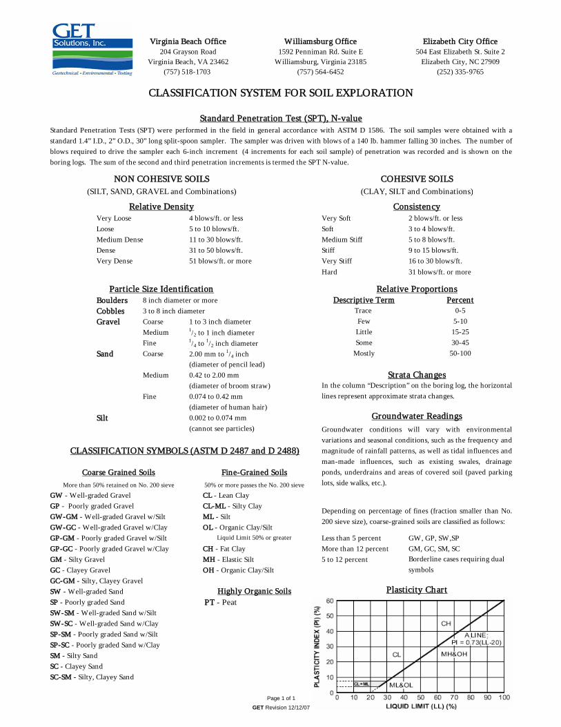
Very Loose 4 blows/ft. or less Very Soft 2 blows/ft. or lessLoose 5 to 10 blows/ft. Soft 3 to 4 blows/ft.Medium Dense 11 to 30 blows/ft. Medium Stiff 5 to 8 blows/ft.Dense 31 to 50 blows/ft. Stiff 9 to 15 blows/ft.Very Dense 51 blows/ft. or more Very Stiff 16 to 30 blows/ft.
Hard 31 blows/ft. or more
Boulders 8 inch diameter or moreCobbles 3 to 8 inch diameterGravel Coarse 1 to 3 inch diameter
Medium 1/2 to 1 inch diameterFine 1/4 to 1/2 inch diameter
Sand Coarse 2.00 mm to 1/4 inch(diameter of pencil lead)
Medium 0.42 to 2.00 mm(diameter of broom straw)
Fine 0.074 to 0.42 mm(diameter of human hair)
Silt 0.002 to 0.074 mm(cannot see particles)
GW - Well-graded Gravel CL - Lean ClayGP - Poorly graded Gravel CL-ML - Silty ClayGW-GM - Well-graded Gravel w/Silt ML - SiltGW-GC - Well-graded Gravel w/Clay OL - Organic Clay/SiltGP-GM - Poorly graded Gravel w/Silt Less than 5 percent GW, GP, SW,SPGP-GC - Poorly graded Gravel w/Clay CH - Fat Clay More than 12 percent GM, GC, SM, SCGM - Silty Gravel MH - Elastic Silt 5 to 12 percent GC - Clayey Gravel OH - Organic Clay/SiltGC-GM - Silty, Clayey Gravel SW - Well-graded SandSP - Poorly graded Sand PT - PeatSW-SM - Well-graded Sand w/SiltSW-SC - Well-graded Sand w/ClaySP-SM - Poorly graded Sand w/SiltSP-SC - Poorly graded Sand w/ClaySM - Silty SandSC - Clayey SandSC-SM - Silty, Clayey Sand
Particle Size Identification
Consistency
Page 1 of 1
GET Revision 12/12/07
CLASSIFICATION SYSTEM FOR SOIL EXPLORATION
Standard Penetration Test (SPT), N-value
Relative Density
NON COHESIVE SOILS(SILT, SAND, GRAVEL and Combinations)
(757) 564-6452
Elizabeth City Office504 East Elizabeth St. Suite 2
Elizabeth City, NC 27909(252) 335-9765
Standard Penetration Tests (SPT) were performed in the field in general accordance with ASTM D 1586. The soil samples were obtained with astandard 1.4” I.D., 2” O.D., 30” long split-spoon sampler. The sampler was driven with blows of a 140 lb. hammer falling 30 inches. The number ofblows required to drive the sampler each 6-inch increment (4 increments for each soil sample) of penetration was recorded and is shown on theboring logs. The sum of the second and third penetration increments is termed the SPT N-value.
Virginia Beach Office204 Grayson Road
Virginia Beach, VA 23462(757) 518-1703
Williamsburg Office1592 Penniman Rd. Suite E
Williamsburg, Virginia 23185
Coarse Grained Soils Fine-Grained Soils
Highly Organic Soils
50% or more passes the No. 200 sieve
Liquid Limit 50% or greater
Trace Few
COHESIVE SOILS(CLAY, SILT and Combinations)
Relative ProportionsDescriptive Term Percent
0-55-10
Strata ChangesIn the column “Description” on the boring log, the horizontallines represent approximate strata changes.
Groundwater Readings
LittleSome
Mostly 50-100
15-2530-45
Groundwater conditions will vary with environmentalvariations and seasonal conditions, such as the frequency andmagnitude of rainfall patterns, as well as tidal influences andman-made influences, such as existing swales, drainageponds, underdrains and areas of covered soil (paved parkinglots, side walks, etc.).
Depending on percentage of fines (fraction smaller than No.200 sieve size), coarse-grained soils are classified as follows:
Borderline cases requiring dual symbols
Plasticity Chart
CLASSIFICATION SYMBOLS (ASTM D 2487 and D 2488)
More than 50% retained on No. 200 sieve