Embed Size (px)
Citation preview
- 1 -
Report of Presidential Ad Hoc Committee for Building Health and Safety under Extraordinary Incidents
On
Risk Management Guidance for Health, Safety and Environmental Security under Extraordinary Incidents
Approved by Board of Directors
26 January 2003 Copyright © 2003 by the American Society of Heating, Refrigerating and Air-Conditioning Engineers, Inc. All rights reserved.
- 2 -
DISCLAIMER
This Report is the result of the efforts of ASHRAE volunteers, and has been funded solely by ASHRAE and the committee members. It has been written with care, using the best available information and soundest judgment possible. Efforts to counter terrorism in the non-military sector present new challenges, but very little data exist to evaluate and predict the nature and likelihood of these intentional incidents. ASHRAE, and the ASHRAE volunteers who contributed to this document, make no representation or warranty, express or implied, concerning the completeness, accuracy, or applicability of the information contained in this Report. No liability of any kind shall be assumed by ASHRAE or the authors of this document as a result of reliance on any information contained in this document. The user shall assume the entire risk of the use of any and all information in this document. Comments, criticisms, suggestions, and additional information pertaining to this report are invited. All communications regarding this report should be directed to the ASHRAE Government Affairs Office, 1828 L St. NW, Suite 906, Washington, DC 20036.
- 3 -
TABLE OF CONTENTS
DISCLAIMER ................................................................................................................................................................................. 2 TABLE OF CONTENTS ............................................................................................................................................................... 3 EXECUTIVE SUMMARY............................................................................................................................................................ 7
Framework .................................................................................................................................................................................. 7 Findings and Conclusions ....................................................................................................................................................... 8
Chapter 2.................................................................................................................................................................................. 8 Chapter 3.................................................................................................................................................................................. 8 Chapter 4.................................................................................................................................................................................. 9 Chapter 5................................................................................................................................................................................ 12
1.0 INTRODUCTION............................................................................................................................................................ 13 1.1 Objective and Scope .................................................................................................................................................. 13 1.2 Background and Lessons Learned ........................................................................................................................ 14 1.3 Overview of this Report ........................................................................................................................................... 15
2.0 RISK MANAGEMENT .................................................................................................................................................. 19 2.1 Demographic Characteristics of Buildings ......................................................................................................... 19 2.2 Underground Facilities ............................................................................................................................................. 19 2.3 A Perspective on Natural, Accidental and Intentional Extraordinary Incidents ..................................... 19
2.3.1 Natural Incidents (e.g., flood, wind, storms, seismic damage).......................................................................... 20 2.3.2 Accidental Incidents (e.g., fire, chemical and other spills, infrastructure damage)........................................ 20 2.3.3 Intentional Incidents (e.g., fire, explosive, CBR, infrastructure damage) ....................................................... 20 2.3.4 Conclusions................................................................................................................................................................. 21
2.4 One Approach to Risk Management .................................................................................................................... 22 2.4.1 Step 1: Risk Analysis.................................................................................................................................................. 23 2.4.2 Step 2: Risk Treatment Planning.............................................................................................................................. 23 2.4.3 Step 3: Risk Treatment Plan Implementation......................................................................................................... 23 2.4.4 Step 4: Revaluate the Plan after Implementation and modify it as needed ...................................................... 24 2.4.5 Conclusions.................................................................................................................................................................. 24
3.0 INFRASTRUCTURE SUPPORT, CONSTRAINTS AND VULNERABILITIES ............................................. 25 3.1 Electric .......................................................................................................................................................................... 25 3. 2 Water ............................................................................................................................................................................ 25 3.3 Sewer ............................................................................................................................................................................. 26 3.4 Flooding ........................................................................................................................................................................ 26 3.5 Fire Protection ............................................................................................................................................................ 26
3.5.1 Fire Command Control Panel................................................................................................................................. 26 3.5.2 Fire Officials .............................................................................................................................................................. 26
3.6 Police.............................................................................................................................................................................. 26 3.7 Communications ......................................................................................................................................................... 27 3.8 Natural Gas .................................................................................................................................................................. 27 3.9 Fuel................................................................................................................................................................................. 27 3.10 Food ............................................................................................................................................................................... 27
3.10.1 Food Security Management................................................................................................................................... 27 3.10.2 Food Security Plan.................................................................................................................................................. 27 3.10.3 Product Tampering ................................................................................................................................................. 28 3.10.4 Product Recall.......................................................................................................................................................... 28 3.10.5 Laboratory Assistance ............................................................................................................................................ 28 3.10.6 Notification............................................................................................................................................................... 28 3.10.7 Emergency Personnel ............................................................................................................................................. 28 3.10.8 Food Security Inspections...................................................................................................................................... 28 3.10.9 Personnel observations .......................................................................................................................................... 28 3.10.10 Investigations......................................................................................................................................................... 28 3.10.l1 Homeland Security................................................................................................................................................. 29
3.11 Mail ................................................................................................................................................................................ 29 3.12 Shipping and Receiving Security ........................................................................................................................... 29
- 4 -
3.13 Transportation ............................................................................................................................................................ 29 3.14 Medical Services ......................................................................................................................................................... 30 3.15 Child Care .................................................................................................................................................................... 30 3.16 Outside Security ......................................................................................................................................................... 30
3.16.1 Building Boundaries ............................................................................................................................................... 30 3.16.2 Property Perimeter .................................................................................................................................................. 30 3.16.3 Outside Lighting ...................................................................................................................................................... 30 3.16.4 Guarded Access ....................................................................................................................................................... 30 3.16.5 Emergency Exits ...................................................................................................................................................... 31 3.16.6 Locks.......................................................................................................................................................................... 31 3.16.7 Storage Tanks........................................................................................................................................................... 31 3.16.8 Personnel Access ..................................................................................................................................................... 31 3.16.9 Personnel Identification ......................................................................................................................................... 31 3.16.10 Vehicle Access........................................................................................................................................................ 31 3.16.11 Parking Areas........................................................................................................................................................ 31 3.16.12 Truck Deliveries .................................................................................................................................................... 31
3.17 Inside Security ............................................................................................................................................................ 32 3.17.1 Restricted Areas....................................................................................................................................................... 32 3.17.2 Access to Central Controls .................................................................................................................................... 32 3.17.3 Building Layout Schematics .................................................................................................................................. 32 3.17.4 Ventilation Isolation................................................................................................................................................ 32 3.17.5 Emergency Alert Systems ....................................................................................................................................... 32 3.17.6 Laboratory Access ................................................................................................................................................... 32 3.17.7 Visitor Access ........................................................................................................................................................... 32 3.17.8 Computer Data Systems ......................................................................................................................................... 33
3.18 Storage Security .......................................................................................................................................................... 33 3.18.1 Access Log ................................................................................................................................................................ 33 3.18.2 Security Inspection.................................................................................................................................................. 33 3.18.3 Regular Inventory.................................................................................................................................................... 33 3.18.4 Hazardous Chemical Storage................................................................................................................................ 33
3.19 Personnel Security ..................................................................................................................................................... 33 3.19.1 Positive Identification ............................................................................................................................................. 33 3.19.2 Controlled Entry...................................................................................................................................................... 34 3.19.3 New Hires ................................................................................................................................................................. 34 3.19.4 Training..................................................................................................................................................................... 34 3.19.5 Personal Items .......................................................................................................................................................... 34
3.20 Personal Protection .................................................................................................................................................... 34 3.21 Conclusions .................................................................................................................................................................. 34
4.0 GUIDANCE AND RECOMMENDATIONS FOR NEW BUILDINGS ............................................................... 37 4.1 General Concepts ....................................................................................................................................................... 37
4.1.1 Goals for Building Performance ............................................................................................................................. 37 4.1.2 Building Vulnerabilities............................................................................................................................................ 37 4.1.3 Commissioning and Documentation....................................................................................................................... 38
4.2 Specific Design Issues and Strategies.................................................................................................................... 38 4.2.1 Outdoor Air Intakes Locations................................................................................................................................ 39 4.2.2 Entry and Egress Locations..................................................................................................................................... 39 4.2.3 Building Envelope and Pressurization................................................................................................................... 39 4.2.4 Fire Protection and Life Safety......................................................................................................................... 39 4.2.5 Air Distribution Systems........................................................................................................................................... 40 4.2.6 Particulate Filters and Air Cleaners...................................................................................................................... 41 4.2.7 Compartmentalization and Areas of Refuge ......................................................................................................... 43 4.2.8 Access to Air Handling Equipment and Ductwork .............................................................................................. 43 4.2.9 Single Point for Disconnecting Utilities ................................................................................................................ 43 4.2.10 Locations and Control of Receiving Areas ......................................................................................................... 44
4.3 HVAC Response and Control Sequences ............................................................................................................ 44 4.3.1 Emergency Systems Shut-down ................................................................................................................................ 44
- 5 -
4.3.2 Emergency Systems Operations............................................................................................................................... 45 4.3.3 Dampers and Damper Leakage................................................................................................................................ 45
4.4 Protective Action Plans ............................................................................................................................................. 45 4.4.1 Plan for Normal Operations..................................................................................................................................... 45 4.4.2 Plan for Emergency Responses ................................................................................................................................ 46 4.4.3 Public Address System ............................................................................................................................................... 46 4.4.4 Emergency Response Drills ...................................................................................................................................... 46
4.5 Commissioning and Building Diagnostics ........................................................................................................... 46 4.5.1 Commissioning............................................................................................................................................................ 47 4.5.2 Recommissioning ........................................................................................................................................................ 47
5.0 GUIDANCE AND RECOMMENDATIONS FOR EXISTING BUILDINGS..................................................... 49 5.1 Operational and Maintenance Issues ................................................................................................................... 49 5.2 Retrofit and Upgrade Issues.................................................................................................................................... 49
5.2.1 Building Envelopes..................................................................................................................................................... 50 5.2.2 HVAC Systems ............................................................................................................................................................. 50 5.2.3 Functional Isolation or Relocation.......................................................................................................................... 51
6.0 REFERENCES ................................................................................................................................................................. 53 APPENDICES................................................................................................................................................................................ 55
Appendix A: Members of ASHRAE Presidential Ad Hoc Committee ..................................................................... 57 Appendix B: Building Demographics ................................................................................................................................ 59
B.1 Number and Size Distribution .................................................................................................................................... 59 B.2 Age Distribution ........................................................................................................................................................... 59 B.3 Function and Use Distribution .................................................................................................................................. 60 B.4 HVAC Equipment Distribution .................................................................................................................................. 60
Appendix C: Risk Management Example ........................................................................................................................ 63 C.1 Determining the Organization’s Level of Exposure ............................................................................................... 63 C.2 Identifying the Risk ....................................................................................................................................................... 66 C.3 Estimating the Probability of Risk Occurrence....................................................................................................... 67 C.4 Value of Loss for Risk Assessment, Step 1 . .............................................................................................................. 67 C.5 Ranking the Risks......................................................................................................................................................... 68 C.6 Identifying the Building’s Vulnerabilities ................................................................................................................ 69 C.7 Life Cycle Cost Analysis.............................................................................................................................................. 69
Appendix D: Personal Protection ....................................................................................................................................... 71 Appendix E: Filtration and Air Cleaning ......................................................................................................................... 75
E.1: Particulate Filtration ................................................................................................................................................... 75 E.2: Gaseous/Vapor Phase Air Cleaning......................................................................................................................... 76

- 6 -
- 7 -
EXECUTIVE SUMMARY Extraordinary incidents, whether caused by war, terrorism, accident or natural disaster, can impact immediate human needs including survival and safety, and also such longer-term needs as air, water, food, and shelter. ASHRAE’s expertise in heating, ventilation, air-conditioning and refrigeration (HVAC&R), and its knowledge of building envelope performance, intake and exhaust air control, air and water treatment, and food preservation is critical in addressing life-safety, and environmental security. Recognizing this increased responsibility for providing guidance for enhanced building performance, the President of ASHRAE appointed a Study Group in October 2001 to provide initial guidance on actions that should be taken to reduce the health and safety risks of occupants in buildings that might be subjected to extraordinary incidents. After the presentation of the Study Group’s Report on 14 January 2002, an ASHRAE Presidential Ad Hoc Committee was appointed to continue the work, and to provide a more comprehensive report to the ASHRAE Board of Directors by January 2003.
The objective of this report is to provide guidance for new and existing buildings regarding protection of air, water, and food systems within buildings. The scope of this report pertains to public use and assembly buildings; commercial, institutional, and educational facilities; and other areas of public assembly such as stadiums, coliseums, and vehicle tunnels and subways. This scope also pertains to those areas of industrial and manufacturing facilities that affect occupancy.
Framework
This Report is based on the framework presented in Figure 1 (see Chapter 1). In this
framework, the first step is to evaluate the risk to a facility of an extraordinary incident. As used in this Report, risk is defined as the “possibility of suffering harm or loss.”1 Based on the level of risk, along with other considerations, the vulnerability of a given building to an extraordinary incident is assessed. As used in this document, vulnerability is defined as “susceptibility to physical injury or attack”2. For example, a building located next to railroad tracks is more vulnerable to a hazardous chemical leak resulting from a train derailment. While all buildings are vulnerable, the degree of acceptable vulnerability for a given building is determined, as noted in Fig. 1, based on those threats (i.e., “indication of impending danger”3) to be addressed, and those that will be accepted based on a low level of likelihood, or on the impracticality or high cost of protection. Next, the infrastructure constraints and vulnerabilities, which are the factors that determine the need for, and practicality of, different protective measures are considered in Chapter 3. These factors include the infrastructure supporting the facility, e.g. utility reliability, cost, currently available technology and existing building characteristics. Finally, protective measures, i.e., options, are considered for new or renovated buildings in Chapter 4, and for existing buildings in Chapter 5. These options are implemented based on the level of “acceptable” vulnerability and the constraints, which, as noted in Fig. 1, in a re-iterative
1 Webster’s II New College Dictionary 1995 edition 2 Webster’s II New College Dictionary 1995 edition 3 Webster’s II New College Dictionary 1995 edition
- 8 -
decision-making process that compares the various options and their constraints before making a decision on which options to implement.
Findings and Conclusions Chapter 2 1. Some characteristics and attributes of buildings can make them more or less of a potential target. To put some of these characteristics in perspective, a summary of commercial building demographic data is provided in Chapter 2 and in Appendix B. This information may be helpful when determining the levels of risk and vulnerability faced by any particular building. However, current statistics are not readily available on the quantity, types, sizes, and systems serving underground spaces. These spaces include vehicle tunnels, subways, garages, and storage facilities.
2. Historical data exist on the occurrence and severity of extraordinary incidents associated with fire, wind, flood, storms, and some criminal activities. However, data on intentional incidents are far more limited and do not enable one to predict the nature, likelihood or severity of future events. Therefore, the guidance presented in this report and the decisions made by building owners, designers and operators are necessarily based on current experience.
• These limitations in our knowledge base are not a justification for the abrogation
of one’s responsibility to deal with the potential risks in a building, but rather an acknowledgement that we are not yet able to base these critical decisions on a well-established body of knowledge.
• Section 2.3 suggests that, despite an increase in the relative percentages of time
that extraordinary incidents occur as a result of terrorist activities, the amount of time that buildings function under normal conditions far exceeds the amount of time under extraordinary incidents.
• These data also lead to the conclusion that the HVAC&R systems must provide a
control sequence continuum from normal operations to effective responsiveness during the occurrence of an extraordinary incident.
3. Risk management, introduced in Section 2.4, is an expanded approach to building design and management. Integrating a comprehensive risk management program with safety, environmental, energy management, and productivity issues is done using standard evaluative methods such as Life Cycle Costing, Benefit-to-Cost ratio, Return On Investment, or simple payback.
Chapter 3 4. Building occupants have come to expect 100% reliability from the infrastructure that serves them. Most are not aware of how vulnerable and interdependent these systems are. Chapter 3 addresses many of the infrastructure systems that may be vulnerable to terrorists. Some outages can prevent building occupancy for days, weeks, or months until they are restored. Also included in this
- 9 -
Chapter are suggested measures and plans that could reduce the risks of disruptions to the infrastructure systems. Similar provisions apply to many types of natural occurrences and occasional outages, although the frequency, duration, and severity of those can be more predictable, based on prior experiences.
5. Onsite infrastructure failures happen regularly, but usually on a manageable scale. Most buildings make provisions for these failures or disruptions as a part of regular maintenance or periodic renovation. However, it may be necessary to perform specific risk and vulnerability assessments of buildings to determine the extent to which the function of any particular building can be compromised by extraordinary events.
• If this is the case, detailed planning by the owner and licensed professionals may be needed that utilizes “what if” scenarios to examine the consequences of unusual and/or multiple situations.
6. Many of the infrastructure issues discussed above are interdependent, and therefore, failure, disruption, or reduction in any one service can impact some of the others. For example, many communication systems rely on electric power for operation. Thus, an electric outage can also mean that communications are not available. As contingency plans are considered to deal with these issues, these interdependencies must be kept in mind. 7. Experience has been gained for dealing with most of these issues to at least some extent by ordinary utility outages, strikes, natural occurrences, or other expected unreliability. While the relative risk of their being impacted by terrorist attacks may be low in an individual building, this possibility and the potential impacts on infrastructure should not be overlooked. Most buildings incorporate some features to back up infrastructure, and can include simple items such as battery backup power supplies for computers and communications equipment, as well as more complex and expensive safeguards, such as emergency generators, redundant electricity, communications, and water service, or combustion driven heating and cooling.
• If the risk of terrorist attack is judged to be sufficiently high, a greater number of redundant or backup features may be desirable and justifiable.
Chapter 4 8. The health, comfort and productivity of building occupants should not be compromised in the name of the reducing building vulnerability to extraordinary incidents.
• Methods for reducing vulnerability from extraordinary incidents should be identified based on a realistic evaluation of the actual risk.
• Many of these measures can also be justified based on the health, productivity and
comfort of the building occupants during normal operations.
• Other features, such as high-performance air filtering techniques, can have a significant impact on first cost and operating cost.
- 10 -
9. In the design of new buildings, care should be exercised in the details of construction and the contractual methods of installation, to assure that the systems will operate in the manner intended.
• When subjected to a life threatening incident, the system becomes a component of
a life safety system, therefore, the “performance as intended” takes on a much more important role. To this end, commissioning the “system” is highly recommended.
• The Owner of the building has the ultimate responsibility in determining the level
of risk, which must be provided for in the design, as well as the vulnerability of the occupants under various scenarios of incidents.
• Once the required performance parameters have been determined, the system,
controls, and machinery should be designed, constructed and operated to achieve the desired level of protection. While design professionals can assist building owners in reducing vulnerability to extraordinary incidents, it is not possible to eliminate all risk.
• The building owner, then, following the successful commissioning performance
verification assumes the responsibility for the ongoing operations
The following findings and conclusions in Chapters 4 and 5 are intended to establish not what steps in system design must be taken, but rather how the design decisions can best be implemented once decided upon. 10. Outdoor air intakes should be located so that they are protected from external sources of contamination, and away from publicly accessible areas in order to minimize obstructions near the intakes that might conceal a device. The use of surveillance cameras and/or intrusion alarm sensors to monitor the intake areas should be considered. These precautions should also provide the added benefit of minimizing the contamination of indoor air from ground applied fertilizers or pesticides, vehicle traffic and similar sources during normal building operation. 11. Entry of visitors, employees, tenants, delivery persons and other special persons should be carefully considered. In addition to providing increased building physical security, it will help minimize the opportunity for a deliberate internal release of an agent. 12. The building envelope should be designed to minimize liquid transfer, as well as air and water vapor infiltration. In addition, the pressurization zones within the building should be maintained at the appropriate values for the functions within them.
• These efforts should reduce both building vulnerability and energy use while providing a healthy and comfortable environment for the increased productivity of the occupants.
- 11 -
• In areas with high humidity, the risk of mold and mildew formation and growth should also be reduced.
13. Life safety issues under many extraordinary conditions require alerting occupants to the situation and providing proper instruction. 14. As biological and radiological particles are in the range of 0.1 to 10 microns (µm), filters should be selected with a highest MERV rating that is physically feasible and economically justified. Significant improvements in protection can be achieved at MERV ratings of 14 through 20 (based on risk assessment and economic analysis). Also, consideration should be given to the need and effectiveness of gas and vapor removal technology to reduce the building vulnerability to chemical agents. As filter and air cleaner efficiencies increase, so do the pressure drops across them, thus, likely requiring larger fans and motors and increased energy cost associated with operating the system.
• The total cost of the filters and air cleaners, including first cost, maintenance cost and operating and energy cost should be evaluated and compared to risk assessment and reduction of vulnerability, as described in Chapter 2.
15. Integrating the control sequences of HVAC systems for normal and extraordinary periods of operation is a critical design issue. Fundamentally, the issue is one of priority control. Given the variations in extraordinary conditions that can occur, a priority scheme must be determined to change from normal control sequences in order to respond to fire, smoke, floods, seismic, wind, and/or accidental and intentional releases of contaminants.
• The priority of control should be decided by the design professional, together with the building owner, based on the relative risk assessments at the particular facility.
16. Plans and drills for responses to extraordinary incidents are essential to the health and safety of the occupants and the first responders.
• Plans to implement these actions should be addressed and refined during the design phases of the building project.
• Full-scale response drills should be held periodically to ensure that the building
occupants, tenants/employees, and first responders understand and practice their duties and responsibilities. These drills should include the operation of the appropriate protective features and the building evacuation, movement of occupants to designated areas within the building, or remaining in the building as appropriate for the emergency or threat being simulated.
17. Commissioning, as described in ASHRAE Guideline 1-19964, and as anticipated to be described in Guideline 0-P5 for commissioning and recommissioning, should be an integral part 4 ASHRAE. 1996. Guideline 1-1996 HVAC Commissioning Process. American Society of Heating, Refrigerating, and Air-Conditioning Engineers, Inc. Atlanta.
- 12 -
of the design process for any new or renovation project. However, the ASHRAE Guidelines do not provide specific performance criteria with which to ascertain intended performance during normal or extraordinary conditions. Therefore, the commissioning processes should be augmented by procedures6 that define specific performance criteria and measures to demonstrate that the building and its systems are: 1) performing as intended under normal conditions; and 2) prepared to respond to extraordinary incidents in accordance with the accepted level of vulnerability, as determined in the risk assessment, Chapter 2. Chapter 5
The objective of this Chapter is to consider some methods that can be effectively employed for existing buildings to meet the risk management strategy established by methods in Chapter 2.
18. As discussed in Appendix B, approximately 4.7 million buildings currently exist in the U.S. that are within the scope of the issues addressed in this Report. Not all of these buildings will reveal sufficiently high risk of intentional attack to justify expenditures for vulnerability reductions. However, some of the buildings do have elevated risk to chemical, biological & radiological (CBR) attacks and have known problems of performance during normal conditions that would affect the ability of the building to respond to the attack, and should be corrected.
• Risk assessments of properties should be conducted, using procedures such as those described in Section 2.4.1. And, based on the results of the risk assessments, risk treatment procedures, similar to those in Section 2.4.2, should be initiated with concentration on changes to maintenance and operational procedures that can be implemented to reduce the vulnerabilities.
19. Essentially all of the options considered for new building design are also applicable to building renovation and retrofit based on the risk, and on the acceptable level of building vulnerability.
• Each of these options should be considered and implemented as appropriate and applicable in retrofit projects. However, with existing buildings some of the options may need to be revised and alternatives selected that will provide a similar reduction in vulnerability while meeting the economic and building features associated with renovations.
5 ASHRAE. 2002. Guideline 0-P: The Commissioning Process. (Unpublished Public Review Document, April 2002). American Society of Heating, Refrigerating, and Air-Conditioning Engineers, Inc. Atlanta. 6 Woods, J.E. 2001. What is Productivity and How is it Measured? In: Productivity and the Workplace. GSA
Office of Governmentwide Policy. December 2001, pp. 33-40.
- 13 -
1.0 INTRODUCTION In April 2002, ASHRAE President William J. Coad appointed the Presidential Ad Hoc Committee for Building Health and Safety Under Extraordinary Incidents to
• Continue the work on issues defined by the previous ASHRAE Presidential
Study Group, • Develop recommendations on specific actions ASHRAE should take, • Coordinate ASHRAE’s activities in this effort with other recognized
engineering and scientific organizations. In June 2002, ASHRAE President Donald G. Colliver reappointed this Ad Hoc Committee with the goal of having this Report completed by January 2003. Since its founding in 1894, ASHRAE has pursued its mission of advancing the arts and sciences of HVAC&R for the public’s benefit. For more than a century, its members have shared ideas, identified the need for research, and written the industry’s standards for testing and practice. These efforts have enabled engineers to provide safer and more productive indoor environments, energy efficiently and cost effectively. Historically, these results have been achieved through compliance with reasonable safety and health requirements established by building codes and standards, which typically have not addressed the threats associated with extraordinary incidents beyond fire and na tural disasters. However, the public’s expectations for buildings to keep occupants safe have been raised as a result of the extraordinary incidents that occurred beginning September 11, 2001. As indicated by trends that are now in evidence, building owners and occupants may now be willing to redirect resources to enhance the performance of buildings to further reduce occupant and building risks associated with extraordinary incidents, while continuing to provide acceptable indoor environments, in an energy efficient and cost-effective manner during normal conditions. 1.1 Objective and Scope The objective of this report is to provide guidance for new and existing buildings regarding protection of air, water, and food systems within buildings. The scope of this report, which includes a continuation of the work defined by the Study Group in its 14 Jan 02 report, pertains to public use and assembly buildings; commercial, institutional, and educational facilities; and other areas of public assembly such as stadiums, coliseums, and vehicle tunnels and subways. This scope also pertains to those areas of industrial and manufacturing facilities that affect occupancy. This report addresses many aspects of building performance that affect health and safety under extraordinary incidents in these buildings and facilities. These aspects include: occupant egress; visitor access; building envelopes; entrance paths for contaminants; refuge areas and decontamination zones; chemical, biological & radiological (CBR) protection; fire protection; smoke removal; air and water filtration; maintenance of air quality; and food and water processes
- 14 -
that involve refrigeration within enclosed facilities. The fundamental parameters of risk/benefit cost, and vulnerability were considered in this study, but the guidance and recommendations provided in this report are limited in both extent and depth, based on the time available to develop this report and on the current state of knowledge. Extraordinary incidents, whether caused by war, terrorism, accident or natural disaster, can impact immediate human needs including survival and safety, and also such longer-term needs as air, water, food, and shelter. ASHRAE’s expertise in HVAC&R, and its knowledge of building envelope performance, intake and exhaust air control, air and water treatment and food preservation is critical in addressing occupant survival, safety, and environmental security. Recognizing this increased responsibility for providing guidance for enhanced building performance, the President of ASHRAE appointed a Study Group in October 2001 to provide initial guidance on actions that should be taken to reduce the health and safety risks of occupants in buildings that might be subjected to extraordinary incidents. After the presentation of the Study Group’s Report on 14 January 2002, an ASHRAE Presidential Ad Hoc Committee was appointed to continue the work, and to provide a more comprehensive report to the ASHRAE Board of Directors by January 2003.
It is important to point out that the problems of extraordinary incidents impact important issues that are not addressed in this report. Noteworthy exclusions are structural integrity, emergency power integrity, security protection, and transportation issues such as food refrigeration and vehicular ventilation. Also, some types of HVAC systems are not included here because of their small size (e.g., window or rooftop units, and split systems that handle only small areas). Equally important items beyond the scope of this report are the destructive effects of conventional and nuclear weapon blast, or incendiary devices. The principal focus of this report is on buildings with larger HVAC and life-safety systems. Note, however, that this report is not based on any specific project, building, design/configuration or HVAC system design.
This report introduces important concepts of risk and vulnerability analyses, which are not typically performed by ASHRAE members. To best determine what measures should be considered for dealing with the potential for attacks by terrorists, it is necessary to evaluate the risks faced by each facility. It is then necessary to evaluate the vulnerability of the particular elements of each building and the measures available for reducing those vulnerabilities. Applying these concepts may often result in concluding that nothing need be done because the risks are minimal or non-existent. 1.2 Background and Lessons Learned
In the 14 January 2002 Report of the Study Group, seven lessons were identified based on the catastrophic events of 11 September 2001, the distribution of anthrax via the postal system, and the actions taken in other buildings known by the members of the Ad Hoc Committee. These lessons focused on methods of protection from intentional incidents, but are also related to accidental and naturally occurring, extraordinary incidents. The Ad Hoc Committee revisited these lessons in the perspective of what has been learned since the Study Group Report. The updated lessons learned include:
- 15 -
1. MMeetthhooddss oo ff pprroo tteecc tt iioonn ffrroomm iinntteenntt iioonnaa ll eexxttrraaoorrdd iinnaarryy iinncc iiddeennttss aarree oo fftteenn rree llaatteedd ttoo
pprrootteecctt iioonn ffrroomm aacccc iiddeennttaa ll aanndd nnaa ttuurraa llllyy ooccccuurrrr iinngg eexxttrraaoo rrdd iinnaarryy iinncc iiddeennttss..
2. Buildings in the U.S. have important safety factors that have proven effective against some threats as a result of the quality of the standards of care practiced in the U.S., as the result of the enforcement of building codes and standards during design and construction, and because of the legal liability of designers, constructors and owners of these buildings.
3. Control strategies that increase preparedness and responsiveness to extraordinary
incidents must not compromise building performance during normal conditions. 4. If protection against aerosol attacks launched from a source exterior to a building is
to be accomplished, then the openings into the building that could allow these airborne aerosols to enter must be capable of timely, complete closure, or be located sufficiently remote from any launch site, or be equipped with adequate filtration.
5. If protection against aerosol attacks launched from a source interior to a building is
to be accomplished, then the space in which the aerosol is released or present must be capable of timely isolation by the closure of all openings communicating with other spaces, or by pressurization to impede migration of the aerosol into uncontaminated areas.
6. Sensors, monitors, and other means of forewarning are not presently available or
not reliable for many contaminants. Therefore, strategies other than feedback control are relied upon today and for the foreseeable future.
7. When areas of refuge are not economically viable in a building, response strategies
should focus on the enhancement of building egress paths and isolation of contaminated areas through the application of commercially available HVAC technology.
8. Enhanced filtration is a desirable, but not sufficient, control strategy to reduce
occupant risk from airborne contaminants, and should be part of a comprehensive strategy that is coupled with pressurization of the building interior relative to the outdoors and improved building envelope air-tightness.
1.3 Overview of this Report
This Report addresses health, comfort, and environmental security issues involving air, water, and food technologies that are within the scope of ASHRAE. These topics are presented in the four chapters that follow this introduction.
Chapter 2,“Risk Management”, presents a risk management strategy, which can be used
to balance the desired level of exposure against risk for a specific building, and shows how to
- 16 -
evaluate its effectiveness. This strategy is based on risk management procedures used in other industries and has been modified and adopted for evaluation of buildings. However, its validity aga inst the unpredictable actions of terrorists may be debatable.
Chapter 3, “Infrastructure Support, Constraints and Vulnerabilities,” identifies
infrastructure support and constraints both outside and inside a building that can impact the effectiveness of air, water and food processing controls during normal and extraordinary operating conditions.
Chapter 4, “Guidance and Recommendations for New Buildings,” considers methods that
could be effectively employed during design of new or renovation projects to meet the risk management strategy suggested by the methods in Chapter 2.
Chapter 5, “Guidance and Recommendations for Existing Buildings” presents some
approaches to addressing the risks that can be effectively employed during operations of existing buildings to meet the risk management strategy established by methods in Chapter 2.
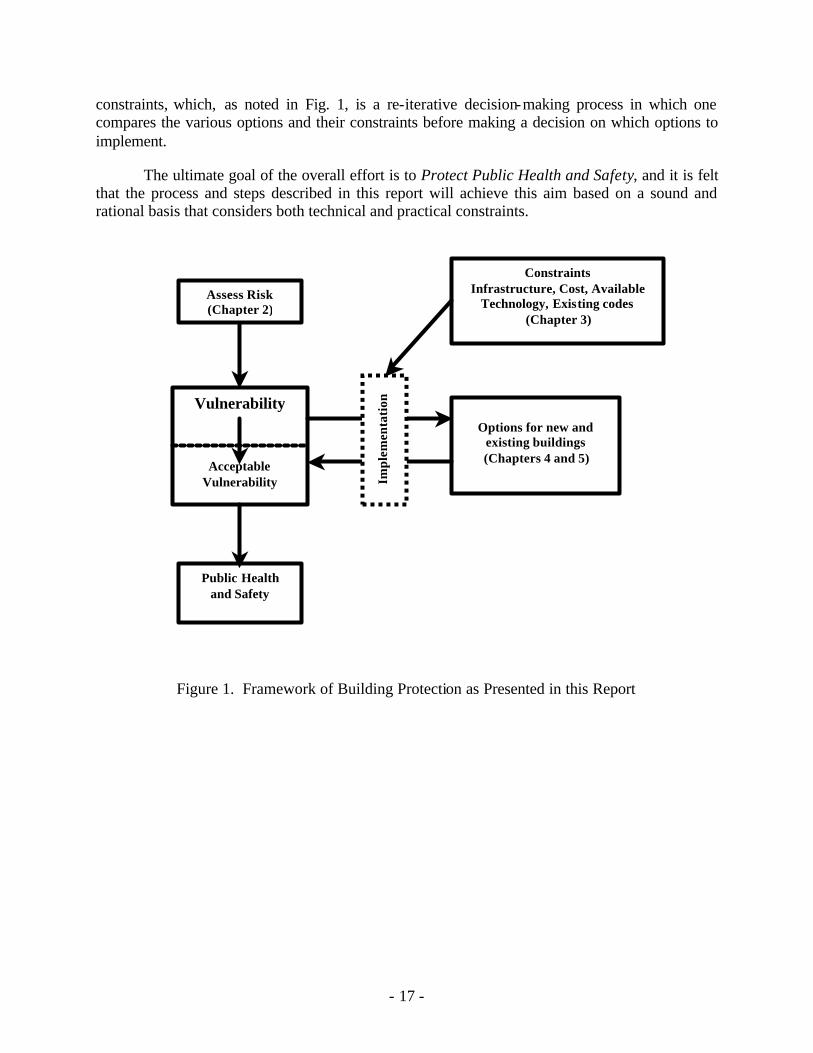
This Report is based on the framework presented in Figure 1. In this framework, the first
step is to evaluate the risk to a facility of an extraordinary incident. As used in this Report, risk is defined as the “possibility of suffering harm or loss.”7 An approach to determining the level of this risk is presented in Chapter 2. As a result of this effort, one can estimate how much one needs to worry. In many buildings, the level of risk may be quite low. There are two components of risk to be considered. The first is the loss itself and is measured in local currency. The second component is the chance of the loss occurring, measured as a probability. For example, there is 1 chance in 2 (0.5 chance) that a coin toss will be heads.
Based on the level of risk, along with other considerations, one moves on to an
assessment of the vulnerability of a given building to an extraordinary incident. As used in this document, vulnerability is defined as “susceptibility to physical injury or attack”8. For example, a building located next to railroad tracks is more vulnerable to a hazardous chemical leak resulting from a train derailment. While all buildings are vulnerable to a degree, one must also determine the acceptable vulnerability for a given building as noted in Fig. 1, which relates to those threats (i.e., “indication of impending danger”9) that one is going to address, and those that one will accept as potential threats based on a low level of likelihood or the impracticality or high cost of protection.
At this point, the remaining three Chapters of this Report come into play. They include the constraints and vulnerabilities described in Chapter 3; these are the factors that determine the need for, and practicality of, different protective measures. These factors include the infrastructure supporting the facility, e.g. utility reliability, cost, currently available technology and existing building characteristics. The protective measures themselves, i.e., options, are described for new or renovated buildings in Chapter 4, and for existing buildings in Chapter 5. These options are implemented based on the level of “acceptable” vulnerability and the
7 Webster’s II New College Dictionary 1995 edition 8 Webster’s II New College Dictionary 1995 edition 9 Webster’s II New College Dictionary 1995 edition
- 17 -
constraints, which, as noted in Fig. 1, is a re-iterative decision-making process in which one compares the various options and their constraints before making a decision on which options to implement.
The ultimate goal of the overall effort is to Protect Public Health and Safety, and it is felt that the process and steps described in this report will achieve this aim based on a sound and rational basis that considers both technical and practical constraints.
Figure 1. Framework of Building Protection as Presented in this Report
Assess Risk (Chapter 2)
Constraints Infrastructure, Cost, Available
Technology, Existing codes (Chapter 3)
Vulnerability
Acceptable Vulnerability
Options for new and
existing buildings (Chapters 4 and 5)
Public Health and Safety
Impl
emen
tati
on

- 18 -
- 19 -
2.0 RISK MANAGEMENT
The objective of this chapter is to describe the use of risk management procedures with which the level of control desired can be ascertained for a specific building. This concept is based on risk management procedures used in other industries and has been modified for evaluation of buildings. As background toward this objective, Sections 2.1 and 2.2 begin with an overview of the demographics of existing buildings and underground facilities in the U.S, and Section 2.3 presents an historic perspective of the frequency of naturally occurring, accidental and intentional extraordinary incidents in buildings worldwide. Risk management, introduced in Section 2.4, is an expanded approach to building design and management. Integrating a comprehensive risk management program with safety, environmental, energy management, and productivity issues is done using standard evaluative methods such as Life Cycle Costing, Benefit-to-Cost ratio, Return On Investment, or simple payback.
In much the same way that fire drills and annual or more frequent inspections by the Fire
Marshall are intended to confirm that risks due to fire and panic are minimized, the risks associated with extraordinary incidents can be reduced by proper operation and maintenance of the building systems.
2.1 Demographic Characteristics of Buildings
Some characteristics and attributes of buildings can make them more or less of a potential target. To put some of these characteristics in perspective, a summary of commercial building demographic data is included in Appendix B. This information may be helpful when determining the levels of risk and vulnerability faced by any particular building. 2.2 Underground Facilities
There are no readily available current statistics on the quantity, types, sizes, and systems serving underground spaces. These spaces include tunnels, subways, garages, and storage. They are found most often in larger cities. Underground facilities frequently have limited or controlled access. Occupancy by people can often be transient and high density. These spaces are usually mechanically ventilated, and occasionally heated or cooled. The ventilation air is rarely treated or filtered. Because of the high density of people and limited access, underground facilities can be at risk, and have been a target, as in the Sarin attack in the Tokyo subway.
2.3 A Perspective on Natural, Accidental and Intentional Extraordinary Incidents Humans have millennia of experience coping with extra-ordinary incidents. The earliest recorded extraordinary incident was the biblical flood which was confirmed in contemporary reports from other civilizations. The solution then, as often the case today, was to modify the occupied space; i.e. build an Ark.
- 20 -
2.3.1 Natural Incidents (e.g., flood, wind, storms, seismic damage)
Floods continue to be the most common, naturally occurring, worldwide extraordinary incidents, with 44 floods in 2002 cited by the UN Relief Organization compared to 20 Earthquakes, 16 Typhoons/Cyclones/Hurricanes, 5 Landslides and 3 major Forest Fires and 3 Biohazard Incidents. These types of natural incidents have led to modification of some building construction codes, but have not led to major changes in normal building operating procedures. 2.3.2 Accidental Incidents (e.g., fire, chemical and other spills, infrastructure damage)
A review of accidental extra-ordinary incidents estimated that in the US alone there are now ~10,000 deaths a year as a result of indus trial accidents. Before 1950, most industrial accidents occurred in coalmines, but there were a few sweatshop fires, tunneling accidents and a fertilizer ship explosion. With the increasing industrialization in the last half of the 20th century, there have been over 200 major toxic chemical accidents. Most occurred in the US, with tens of thousands restricted indoors, and hundreds evacuated until the threats dissipated. In India, a toxic gas release at a US company plant in Bhopal killed ~7000 people living in minimal shelters near the plant. There were also a number of oil tanker spills and pipeline explosions, as well as three nuclear plant incidents; one in England (fire), one in the US (Three Mile Island Reactor) and one in USSR (Chernobyl), the latter with ~8,000 immediate deaths, plus many more subsequent early deaths from radiation exposure. As a result of such accidental incidents, there have been major changes in some building codes and/or operating procedures, primarily with respect to fire and smoke control, and building egress. 2.3.3 Intentional Incidents (e.g., fire, explosive, CBR, infrastructure damage)
Terrorist caused extraordinary incidents have occurred for thousands of years, often with government sanction (e.g., piracy under Letters of Marque; hired mercenaries to attack non-combatants) to disrupt supply lines, divert troops to protect civilian populations or induce surrender without battle in hopes of avoiding total elimination. But there has been a proliferation of terrorist activities since the 1960’s, perhaps in part because of increased information on manufacture and availability of powerful explosives, coupled with easier international travel. The first commercial airliner hijacking occurred in 1961, and between 1968 and 1969 three US Ambassadors were attacked, kidnapped or massacred in foreign countries. There were 11 international terrorist incidents during the 1970’s including the “Bloody Friday” bombings in Ireland; the Munich Olympics massacre, the assassinated US Ambassador to Sudan and other diplomats; bombs were exploded on Wall Street and at a government office building in Washington, DC; an Air France airliner was hijacked to Entebbe; the US Embassy in Teheran was seized, taking 66 Americans hostage, holding 53 of them for over two months; and terrorists seized the Grand Mosque in Mecca, The pace of terrorist activities increased to 32 incidents during the 1980s. World leaders Anwar Sadat in Egypt, PM Gandhi in India, PM Gemayel in Lebanon and the DeutscheBank Chairman in Germany were assassinated and many other officials were kidnapped or assassinated. US military bases and personnel were bombed: a USAF base in Ramstein Germany; in Beirut, Lebanon the Marine Barracks (242 dead), a French Military base (58 dead)
- 21 -
and the US Embassy. Sites frequented by US troops were also bombed, including a USO Club in Italy, a West Berlin nightclub, a restaurant in Spain and a Greek Air Force bus transporting US military in Athens. Other countries were also targeted, a South Korean delegation was bombed in Burma. Air transport was increasingly targeted: a TWA flight to Rome was hijacked, an Air India flight was blown up, two Air Canada cargo handlers were killed at the Tokyo Airport, an Air Egypt flight was hijacked, South Korea’s Seoul Airport was bombed, and Korean Air flight 858 was shot down over the Indian Ocean, killing all aboard; a bomb was detonated at Athens Airport, killing 4 Americans on incoming TWA flight 840 and Pan Am Flight 103 was blown up over Lockerbie, Scotland, killing all 259 aboard. And the Italian Cruise Liner Achille Lauro was hijacked with 700 passengers aboard.
Even more terrorist incidents occurred during the 1990s, with 73 incidents worldwide. The US Embassies in Tanzania and Kenya were bombed almost simultaneously. The Israeli Embassy in Argentina, the Egyptian Embassy in Pakistan, the Greek Embassy in Vienna and the Burmese Embassy in Thailand were attacked. At a U.S base in Saudi Arabia, a military housing complex was attacked with truck- laden explosives that caused partial progressive collapse with loss of life. There were fewer aircraft incidents; an Air France flight to Algeria and an Air India flight to Delhi were hijacked, and a UN flight on Air Angola was shot down. However there were 16 bombing incidents of public facilities: the USIS Library in Manila, a Paris subway, the NY World Trade Center, the Oklahoma Federal building, the Central Bank in Sri Lanka, bombings in London and Manchester in England as well as several in Northern Ireland. Two buses were bombed in Jerusalem and a mall bombing left 8 dead and ~ 200 injured. There was an oil pipeline bombing in Colombia, a hotel bombing in Cuba and a bar bombing in Uganda. The number of shooting incidents increased tremendously: NYC Empire State Building, many incidents in Israel, and increasing numbers of kidnappings and murders in Sudan, Yemen, Pakistan, Georgia, Russia and Tajikistan; Colombian abductions increased dramatically, with ransoms demanded in many cases. Newer terrorist technologies were introduced, with letter bombs sent from Egypt to Washington, DC, NY City, London and Saudi Arabia, and chemical weapons (nerve gas) were used in attacks in subways in Tokyo and Yokohama. In the first two years of the 21st century, it is clear that the number and intensity of terrorist incidents are increasing, becoming more lethal and being initiated by rebels in more countries than ever. The attack with hijacked airliners on the NYC World Trade Center Towers, and the Pentagon, and introduction of biological weapons (Anthrax disseminated in letters to a number of sites) has led to worldwide recognition of the growing problems of terrorism.
Coalition-building toward reaching solutions has proven difficult and it appears that the number of terrorist extra-ordinary incidents will continue to increase. Since buildings provide the first line of defense against many terrorist acts it seems clear that, while normal building design, operations and controls should not be compromised, some modifications should be considered and responsive control is required to deal with many extra-ordinary events. 2.3.4 Conclusions As production and wide-scale distribution of hazardous chemicals have increased over the last half-century, the number of large scale accidental extraordinary incidents has been growing,
- 22 -
despite increasing governmental regulations, inspections, fines and programs to reduce them. Humanity has been learning how to cope with such incidents and, regrettably it appears, must now add an increasing threat of extraordinary incidents as a result of terrorist activities to the problems it must learn to cope with. This section suggests that, despite an increase in the relative percentages of time that extraordinary incidents occur as a result of terrorist activities, the amount of time that buildings function under normal conditions far exceeds the amount of time under extraordinary incidents.
As noted above, historical data exist on the occurrence and severity of extraordinary incidents associated with fire, wind, flood, storms, and some criminal activities. However, data on intentional incidents are far more limited and do not enable one to predict the nature, likelihood or severity of future events. Therefore, the guidance presented in this report and the decisions made by building owners, designers and operators are necessarily based on current experience. These limitations in our knowledge base are not a justification for the abrogation of one’s responsibility to deal with the potential risks in a building, but rather an acknowledgement that we are not yet able to base these critical decisions on a well-established body of knowledge. 2.4 One Approach to Risk Management
Risk Management is a systematic approach to the discovery and treatment of risks facing an organization or facility. The goal is to help objectively state, document, and rank risk, and prepare a plan for implementation. The process includes four steps:10
1. Risk analysis 2. Risk treatment planning 3. Risk treatment plan implementation 4. Re-evaluating the plan after implementation, and modifying it as needed.
These steps, originally developed for financial planning, have been adapted to managing
other types of risk. As guidance in this Report, the following application of these steps is suggested: In the first step, a risk analysis (i.e., risk assessment) should be conducted to identify the threats, the value of the probable losses, and system vulnerabilities. The second step should be to identify options that can reduce vulnerabilities, mitigate the risks and provide protection to acceptable levels. These options are then analyzed for their impact on total system performance, cost estimated, and prioritized for implementation. In the third step, the selected set of prioritized options should be designed into a coherent plan, installed, and commissioned. And, in the fourth step, the installed and commissioned system should be periodically re-evaluated to provide assurance that it continues to meet current needs. If or when the performance of the installed system is found to be less than expected, this four-step process should be repeated.
In this section of the Report, each of the four steps is outlined. To provide additional
guidance, a further discussion of the process is provided in Appendix C, together with an example.
10 Fundamentals of Financial Planning Second Edition by Robert M Crowe and Chares E. Hughes, The American College, Page 222-223.
- 23 -
2.4.1 Step 1: Risk Analysis.
Risk analysis, itself, is a multi-step process involving:
1. Determining the Organization’s Level of Exposure. 2. Identifying the Risk 3. Estimating the Probability of Risk Occurrence 4. Determining the Value of the Loss 5. Ranking the Risks 6. Identifying the Building’s Vulnerabilities
2.4.2 Step 2: Risk Treatment Planning
This step involves options, methods, cost and procedures developed to mitigate or counter the risk or vulnerability. The question is “which method or methods are chosen to handle the risk?”
Tasks in Step 2 include:
• Developing Options to Mitigate the Risk and Developing Cost to Implement • Evaluating and Ranking the Options
Loss control is the risk management strategy used in this Report. It is defined as
activities designed to reduce the possibility of loss or to minimize the magnitude of the losses that actually occur. For example, in heating and air conditioning terms, moving the location of an outside air intake could significantly mitigate the risk of a chemical or biological attack on a facility by reducing the possibility of the loss occurrence.
2.4.2.1 Developing Options to Mitigate the Risk and Cost to Implement The list of vulnerabilities (from 2.4.1.6 in the Risk Analysis section) may be used to
develop solutions and to compare their costs to those risk and vulnerabilities. The order list from the risk rating chart and the human judgment activity may be used. A new probability for the risk should be estimated before the counter measures are implemented.
2.4.2.2 Evaluating and Ranking the Options Life Cycle Cost is one method to evaluate and rank the options. The Base case is the
current situation before mitigation. An example of using this method is presented in Appendix C. Other methods are Benefit-to-Cost Ratio, Return-on-Investment, and Simple Payback. 2.4.3 Step 3: Risk Treatment Plan Implementation
The information from the Risk Mitigation Plan can be used to begin planning for the implementation. If dealing with multiple buildings, Table C-8 in the Appendix can be expanded
- 24 -
to prioritize their implementations. In this third step, the selected set of prioritized options should be designed into a coherent plan, installed, and commissioned, using procedures such as the ASHRAE Guideline 0-P: The Commissioning Process. 2.4.4 Step 4: Revaluate the Plan after Implementation and modify it as needed
The plan should be reviewed periodically to ensure its effectiveness. If a plan is not meeting its objectives, either the plan or the objectives should be modified to ensure its effectiveness. One sign of a successful plan is its continual review and modification to meet the users needs. If or when the performance of the installed system is found to be less than expected, this four-step process should be repeated.
2.4.5 Conclusions
The use of a risk management approach: § Identifies which risks are the most critical and need the most resources. § Is flexible and can be adapted to any organization’s needs and resources. § Creates a written history of risk analysis, mitigation evaluation, and
implementation. § Encourages discussion about risk, requirements, and technologies. § Promotes periodic review to ensure the organization’s needs are met. § Can involve a diverse group to bring broad range experiences and expertise to
solve the problem. See Appendix C.2 “Identifying the Risk” One way to significantly reduce the magnitude of loss is for the organization to return to
normal business as quickly as possible. This is accomplished by the organization’s business resumption plan. Business resumption plans are beyond the scope of this paper. There are consultants that can assist an organization in the development of a business resumption plan. Information and resources can be found on the web by using a search engine and the phrases “business resumption” or “business recovery.” FEMA, the Federal Emergency Management Agency, has a web site at www.fema.gov dedicated to business resumption and emergency planning.
- 25 -
3.0 INFRASTRUCTURE SUPPORT, CONSTRAINTS AND VULNERABILITIES The objective of Chapter 3 is to identify infrastructure constraints and vulnerabilities, both outside and inside the building, that can impact the effectiveness of air, water and food processing control during normal and extraordinary operating conditions and that may impact decisions regarding various proactive and reactive response strategies. Building owners and occupants have come to expect 100% reliability from the infrastructure that serves them. Most are not aware of how vulnerable and interdependent these systems are. This Chapter addresses many of those infrastructure systems that may be vulnerable to terrorists. Some outages can prevent building occupancy for days, weeks, or months until they are restored. Also included in this Chapter are suggested measures and plans that could reduce the risks of disruptions to the infrastructure systems. Similar provisions apply to many types of natural occurrences and occasional outages, although the frequency, duration, and severity of those can be more predictable, based on prior experiences. Where the potential for infrastructure risk exists, consider making provisions that minimize the vulnerability of a facility. 3.1 Electric A single electric distribution circuit serves most buildings from a utility substation. While many substations have multiple feeds, reliability of electric service can be disrupted by failure of the substation or distribution circuit. To avoid power disruptions, the electrical system could have power supplied from two different sources coming to a common point in the switchgear where the building operator can change the source as necessary. Back-up electric generators, which are sometimes required by code, can also be installed onsite to operate critical functions as determined during design or renovation. Switchgear, motor control centers, power distribution panels, and generators should be secured against unauthorized entry. Utility companies should review their susceptibility to terrorist damage, survey critical areas, and ensure that backup/replacement equipment is on-site if procurement of replacements requires long lead-time. 3. 2 Water
The potential exists for public water supplies to be disrupted or contaminated. While disruption is noticed immediately, contamination may not be discovered for some time. Outside access to wells and potable water tanks could be used when such events occur; if they are to be, then these systems need to be secured from unauthorized entry.
Potable and non-potable water lines in the building should be inspected periodically for vulnerability and possible tampering. All potable water and ice-making equipment, and storage facilities should have controlled access. Arrangements should be made for immediate notification in the event the potability of the public water supply is compromised
- 26 -
3.3 Sewer The potential exists for public sanitary sewers to be disrupted or shut down. Disruption is noticed almost immediately, and could require evacuating buildings, unless an alternate method for waste disposal is available. Installing storage facilities or a treatment plant can increase sewerage reliability. 3.4 Flooding Removal of storm water from buildings by public systems is subject to disruption by blocking flow, thus causing storm water to back up and flood buildings and streets. Having alternate means for storm water disposal, such as retention ponds, may provide some relief. Breeching of dams and flood control structures can cause flooding by streams and rivers. Blocking of natural watercourses can also cause flooding in areas never before considered. In the future, siting of critical buildings or occupied portions of buildings in areas where flooding is likely by natural or manmade causes should be avoided. 3.5 Fire Protection Availability of public fire protection water supplies can be limited when there are multiple fires. Similarly, with multiple fires, there may not be enough fire apparatus and personnel to deal with all of them. Also, fire departments must have unimpeded access, i.e., unlimited by flooding or blockage of roads or bridges. Installing on-site water storage for fire protection reduces dependency on public supplies. Training and equipping select building personnel with fire fighting capabilities can provide some help. For additional guidance on fire protection and life safety see Section 4.2.1.4. 3.5.1 Fire Command Control Panel
The Fire Command Control Panel should be located in an obvious place at the entrance of the building or guardhouse, in accordance with local requirements. The panel should be secured so that only the proper personnel can access it. 3.5.2 Fire Officials Fire officials should be familiar with the building and its contents and systems so that they are aware of particular hazards and building fire equipment at their disposal. 3.6 Police With major or multiple attacks, police may not be able to respond to all emergency calls. Also, police must have unimpeded access, unlimited by flooding or blockage of roads or bridges. Police officials should be familiar with the building and its contents and systems so that they are aware of particular hazards and of unique building features. An emergency plan should make alternate provisions in the event these services are not available.
- 27 -
3.7 Communications Telephone, fiber optic, and cable communications systems and their facilities can be lost if either the distribution system or main facility is disrupted. Even wireless communications systems are vulnerable to disruption if the relay stations or main services are disabled. Remember that most of those facilities are dependent on many of the same utilities that buildings require. Handheld communicators, 2-way communicators, or multiple systems can increase reliability. Historically, amateur radio operators (“Ham Operators”) have provided essential communications in natural calamities. These radio operators should be contacted in advance of need. 3.8 Natural Gas Natural gas systems serving buildings can be disrupted by pipeline breaks or explosions, or by loss of pumping or compressor stations that move the gas. Having alternate fuel supplies for some natural gas equipment, such as propane or fuel oil, can allow limited continued operation. For smaller equipment, such as cooking or water heating, dual fuel equipment is not readily available, so equipment using other fuels must be available if continued operation is required. 3.9 Fuel Fuel supplies for buildings, other than natural gas, come from depots or bulk plants, which are subject to being destroyed. These fuels can be delivered from other locations, at greater cost and time. Most fuel supplies for buildings, other than natural gas, have storage facilities on site. Note that natural gas pipelines are subjected to both natural catastrophes and terrorist activities. The building fuel storage facilities must be large enough to handle an interruption of delivery and must be located in a secure, monitored area. 3.10 Food Those buildings where food is served depend on frequent deliveries and on utilities for refrigeration and preparation. Thus, food production and service can be compromised by the inability to deliver supplies or lack of utilities. Increased on-site food processing and storage along with alternate utilities can reduce the dependency on deliveries and external utilities. 3.10.1 Food Security Management
A food security management team and a food security management coordinator should be
identified for each building. Each member should be assigned clear responsibilities.
3.10.2 Food Security Plan
A food security plan using established risk management principles should be developed and implemented. The plan should include procedures for handling threats, actual cases of product tampering and an evacuation plan for each building. Members of the food security management team should be trained in all provisions of the plan with drills conducted periodically. The plan should be reviewed and revised as needed.
- 28 -
3.10.3 Product Tampering
Corrective action taken in all cases of product tampering should ensure that adulterated or potentially injurious products are not released for consumption.
3.10.4 Product Recall
The plan should include the immediate containment or recall of adulterated products from trade and consumer channels. Safe handling and disposal of products contaminated with chemical or biological agents should also be included in the plan.
3.10.5 Laboratory Assistance
A relationship should be established with appropriate analytical laboratories for possible assistance in the investigation of food or product tampering incidents.
3.10.6 Notification
The plan should detail procedures for notifying appropriate law enforcement and public health officials when a food security threat is received, or when evidence of actual product tampering is observed.
3.10.7 Emergency Personnel
Specifically designated entry points for emergency personnel should be identified in the plan. An on-site contact person familiar with the building characteristics or having access to HVAC&R design plans and operational procedures and maintenance should be designated and should be at the designated entry point in an emergency.
Current local, State and Federal Government Homeland Security contacts and Public Health officials should also be listed in the plan. This list should be updated regularly.
3.10.8 Food Security Inspections
Food security inspections of the building should be conducted regularly by officials to verify key provisions of the plan.
3.10.9 Personnel observations
All personnel should be encouraged to report any sign of possible product tampering or break in the food security system.
3.10.10 Investigations
All threats and incidents of intentional food or product tampering should be immediately investigated and reported to law enforcement officials and the Food Safety and Inspection Service (FSIS)/State Inspector in-Charge.
- 29 -
3.10.l1 Homeland Security Liaison with local Homeland Security officials and other law enforcement officials should be pre-established by the food security management team. 3.11 Mail The influx of mail into the building provides a conduit for the introduction of hazardous materials. If possible, mail handling should be done in a separate room or building, away from heavy concentration of personnel and food production/processing operations. The ventilation/airflow within the mailroom should be separate from the rest of the system (in new or retrofitted designs). Existing buildings could try to achieve air isolation by filters, dampers or unit heater/air conditioner installation. Mail handlers should be trained to recognize and handle suspicious pieces of mail, using U.S. Post Office guidelines.11 3.12 Shipping and Receiving Security Delivery of items is necessary in every building or business. These same deliveries can be compromised to include terrorist’s materials, convey needed materials to terrorist’s hands, or contaminate and then distribute legitimate shipments. Care must be taken to avoid any of these situations.
All outgoing shipments should be sealed with tamper-proof, numbered seals that are included on the shipping documents if warranted by the level of risk. Management should require that incoming shipments be sealed with tamper-proof, numbered seals, and that the seal numbers be shown on the shipping documents for verification prior to entry into the building if warranted by the level of risk. Shipping documents with suspicious alterations should be thoroughly investigated. All trailers on the premises should be locked and sealed when not being loaded or unloaded. A policy for off-hour deliveries should be established to ensure prior notice of such deliveries and require the presence of an authorized individual to verify and receive the shipment. Packaging integrity of all incoming shipments should be examined at the receiving dock for evidence of tampering. Advance notification (by phone, e-mail, fax) should be required from suppliers for all incoming deliveries. Notification should include pertinent details about the shipment, including the name of the driver. Loading docks should be secured to avoid unverified or unauthorized deliveries.
3.13 Transportation People and supplies depend on transportation for access to buildings. Review of literature and discussions with professionals in this field revealed that there are no current statistical data available to do risk management assessment for automobile, busses and trolleys. These vehicles have large air changes that occur as compared to buildings and trains, which have less leakage and may not have operable windows. Studies are also underway to address ventilation of tunnels and subways that may be vulnerable to extraordinary incidents.
11 A Mail Center Security Handbook is available from the U.S. Postal Service at
www.usps.com/news/2001/press/pr_011022gsa.
- 30 -
3.14 Medical Services People require routine and emergency access to medical services. If those services are not available locally for any reason, people in emergency situations are put at risk. Those requiring routine services may be hindered by lack of transportation or by congestion when seeking those services, if not available locally. Adequate amounts of first aid supplies should be present to handle injuries. The supplies should be located strategically, so that individuals in all sections of the building can readily receive treatment. A core group of the staff should receive adequate training to administer first-aid. 3.15 Child Care Many who work in buildings are able to do so because they can get convenient and safe child care services. Should there be any risk associated with child care, some may not want to take those risks, and may not be available for work. This could diminish the ability of some organizations to function adequately. Location of the child care services within the building should be easily accessible for building and emergency personnel, yet be secure from outside intruders. 3.16 Outside Security The perimeter of the property and the building boundaries are definite lines of defense against intrusions. Care must be taken to limit access to every entry point by a thorough inspection for possible entry points and a remedy for each point found. 3.16.1 Building Boundaries
Doors, windows, balconies, patios, etc., should be secured to prevent unauthorized entry.
3.16.2 Property Perimeter
The perimeter of the property should be monitored for signs of suspicious activity or unauthorized entry.
3.16.3 Outside Lighting
Outside lighting should be sufficient to allow detection of unusual activities; motion or IR sensitive sensors that automatically turn on temporary area illumination are inexpensive and readily available.
3.16.4 Guarded Access
Security of all access points should be considered by methods such as guards, alarms, cameras or other security hardware, consistent with national and local fire and safety codes.
- 31 -
3.16.5 Emergency Exits
Emergency exits should be alarmed and have self- locking doors that can be opened only from the inside.
3.16.6 Locks
All doors, windows, roof openings, and vent openings should be secured (e.g., locks, seals, sensors) at all times, consistent with fire and life safety requirements.
3.16.7 Storage Tanks
Storage tanks for hazardous materials, fuels and potable water supply should be protected from, and monitored for, unauthorized access, and should be walled off from external small arms fire.
3.16.8 Personnel Access
An updated list of personnel with open or restricted access to the building should be maintained at the security office.
3.16.9 Personnel Identification
Methods of positive identification (e.g., picture IDs, sign- in and sign-out at security or reception area) should be considered to control entry into buildings. Areas requiring higher security may require key entrances or more advanced access limitation technologies (e.g., handprint, voice identification).
3.16.10 Vehicle Access
Incoming and outgoing vehicles within the property (both private and commercial) should be inspected for unusual cargo or activity.
3.16.11 Parking Areas
Parking areas for visitors or guests should be situated at a safe distance from the buildings on the property. Vehicles of authorized visitors, guests and employees should be clearly marked (e.g., placards, decals, etc.).
3.16.12 Truck Deliveries Truck deliveries should be verified against a roster of scheduled deliveries. Unscheduled deliveries should be held outside the building property, pending verification of shipper and cargo by recipient.
- 32 -
3.17 Inside Security
The building interior cannot be assumed to be safe from incident; perpetrators could be building employees, legitimate clients or contractors present in the workplace. Security measures inside the building should be adequate to prevent disruption or introduction of a hazardous material. 3.17.1 Restricted Areas
Restricted areas inside the building should be clearly marked and secured.
3.17.2 Access to Central Controls
Access to central controls for airflow, water systems, electricity, communications, gas
and security should be restricted and controlled. 3.17.3 Building Layout Schematics
Updated building layout schematics should be available at strategic and secured locations
in the building. 3.17.4 Ventilation Isolation
Ventilation systems should include a provision for immediate isolation of contaminated
areas. 3.17.5 Emergency Alert Systems
Emergency alert systems should be fully operational and tested; locations of controls
should be clearly marked. 3.17.6 Laboratory Access
Access to laboratory facilities should be strictly controlled. Comprehensive, validated
security and disposal procedures should be in place, particularly for the control of reagents, hazardous materials and live cultures of pathogenic bacteria. 3.17.7 Visitor Access
Visitors, guests and other non-building employees (contractors, salespeople, truck
drivers, etc.) should be restricted to common areas unless accompanied by an authorized building representative.
- 33 -
3.17.8 Computer Data Systems Computer data systems should be protected using passwords, network firewalls and
effective, current virus detection systems. Encryption or other similar security techniques should be considered for wireless computer networks. . 3.18 Storage Security
Storage areas are often closets, cabinets, and basement areas that are not readily noticed by building occupants. Hazardous materials or explosives can be hidden in these areas for later use without alarming the building staff. The building’s own supply of volatile or hazardous materials can also be utilized and must be secured.
3.18.1 Access Log
Controlled access should be maintained for all sensitive product and ingredient storage
areas. An access log should be maintained. 3.18.2 Security Inspection
Security inspection of all storage facilities (including temporary storage vehicles) should
be performed regularly, and the results logged. 3.18.3 Regular Inventory
A regular inventory of hazardous chemicals or other products should be made, and all
discrepancies should be investigated immediately. The frequency of inventory checking should be dependant on the risk involved. 3.18.4 Hazardous Chemical Storage
Hazardous chemical storage areas or rooms should be secured and isolated from other
parts of the building. The storage areas should be constructed and safely vented in accordance with national or local building codes and standards. 3.19 Personnel Security
The large numbers of people working, entering, or maintaining buildings make personnel security important and necessary. 3.19.1 Positive Identification
A system of positive identification/recognition of all building employees should be in
place.
- 34 -
3.19.2 Controlled Entry Procedures should be established for controlled entry of employees into the building
during both working and non-working hours. 3.19.3 New Hires
New hires (seasonal, temporary, permanent, and contract workers) should be subjected to
background checks before hiring. 3.19.4 Training
Orientation training on security procedures should be given to all building employees.
3.19.5 Personal Items
The building managers should establish and enforce a policy on what personal items may
and may not be allowed inside the building and within production areas. 3.20 Personal Protection Three routes of CBR entry can be considered to attack a human. The oro-nasal entry is the most obvious for most agents. Also, many agents can attack and enter skin. The third route, “cross contamination”, involves deposit on the skin (or clothing) surface with subsequent release into the air for entry into the body through the oro-nasal portal.
Details on protective clothing, and its limitations are presented in APPENDIX D. At present, if any stockpiling of protective clothing/equipment is undertaken, it should be limited. Power air supplied (battery powered) respiratory hoods (not masks) could be considered. For protective clothing, at most, simple plastic, hooded ponchos might be considered. These caveats are based on the very real problems of donning and sealing, the current lack of standards, extensive requirements for fitting and testing of fit, the resultant physiological and psychological strains of wear, and the lack of facilities for decontamination prior to removal in order to avoid cross contamination.. 3.21 Conclusions Onsite infrastructure failures happen regularly, but usually on a manageable scale. Most buildings make provisions for these failures or disruptions as a part of design, regular maintenance or periodic renovation. However, it may be necessary to perform specific risk and vulnerability assessments of buildings to determine the extent to which the function of any particular building can be compromised by extraordinary events. If this is the case, detailed planning may be needed that utilizes “what if” scenarios to examine the consequences of unusual and/or multiple situations.
- 35 -
For those items or services that are expected to fail periodically based on experience, spares parts or systems are sometimes kept on site unless they are known to be readily available locally. Replacing others can take weeks or months. Also, depending on the extent of an incident, unusually high demand or interruptions in transportation services may also lead to longer delivery times. Many of the infrastructure issues discussed above are interdependent, and therefore, failure, disruption, or reduction in any one service can impact some the others. For example, many communication systems rely on electric power for operation. Thus, an electric outage can also mean that communications are not available. As contingency plans are considered to deal with these issues, these interdependencies must be kept in mind. Experience has been gained for dealing with most of these issues to at least some extent by ordinary utility outages, strikes, natural occurrences, or other expected unreliability. While the relative risk of their being impacted by terrorist attacks may be low in an individual building, this possibility and the potential impacts on infrastructure should not be overlooked. Most buildings incorporate some features to back up infrastructure, and can include simple items such as battery backup power supplies for computers and communications equipment, as well as more complex and expensive safeguards, such as emergency generators, redundant electricity, communications, and water service, or combustion driven heating and cooling. If the risk of terrorist attack is judged to be sufficiently high, a greater number of redundant or backup features may be desirable and justifiable.

- 36 -
- 37 -
4.0 GUIDANCE AND RECOMMENDATIONS FOR NEW BUILDINGS
The objective of Chapter 4 is to consider methods that can be effectively employed during design of new or renovation projects to meet the risk management strategy established by the methods in Chapter 2. Section 4.1 begins an overview of general concept that should be employed to ensure acceptable performance during normal and extraordinary conditions. Section 4.2 identifies several basic system design alternatives that can reduce building vulnerabilities (4.2.1) and additional design alternatives that can further reduce building vulnerabilities (4.2.2). Section 4.3 introduces the concept of prioritizing the control sequences of HVAC systems for normal and extraordinary periods of operation, including control sequences to respond to fire, smoke, floods, seismic, wind, and/or accidental and intentional releases of contaminants. In Section 4.4, guidance for the development and implementation of Protective Action Plans is presented, and in Section 4.5, the need for Commissioning and Recommissioning of buildings and their systems is addressed. 4.1 General Concepts
Since the acts of September 11th there is an increased awareness in the engineering community of the importance of building safety and protection under extraordinary incidents even though the probability of such an incident at any individual building is very remote. Economic wisdom and a realistic risk analysis may limit the protective measures to be employed. In some cases, enhanced security can be provided for in both new facilities and retrofit projects at little or no additional burden in investment cost by simply including the considerations for safety and security under extraordinary incidents as an additional design parameter. In other cases indicated by risk assessments, additional reductions in building vulnerability can be provided, but often at a significant increase in cost. 4.1.1 Goals for Building Performance Buildings should be routinely conceived and designed to comply with acceptable criteria for health, safety and productivity of the occupants; to be comfortable; to provide pleasant environments; to result in building and equipment energy efficiency; and to accommodate ease of constructability, maintainability and accessibility of equipment and system components. Concern regarding these criteria is heightened by the risk of extraordinary incidents. The long term health, comfort and productivity of building occupants should not be compromised in the name of the reducing building vulnerability to extraordinary incidents. Realistic measures that will reduce building vulnerability under extraordinary incidents should not have a negative impact and in many cases may improve the health and comfort of the indoor environment. 4.1.2 Building Vulnerabilities Methods for reducing vulnerability from extraordinary incidents should be identified based on a realistic evaluation of the actual risk. Many of these measures can also be justified based on the health, productivity and comfort of the building occupants during normal operations. Other features, such as high-performance air filtering techniques, can have a
- 38 -
significant impact on first cost and operating cost. The first step is to define the threat and the acceptable level of building vulnerability. The construction team should take measures, from groundbreaking to the completion of the construction activities, to assure that the project has been built without breach of security, which could result in or augment current or future incidents. 4.1.3 Commissioning and Documentation
The building envelope, HVAC system and controls, electrical systems and similar features that will impact the operation of the building, as well as its vulnerability should be periodically reviewed, preferably through a commissioning process as each construction phase of the building is completed. Although commissioning is typically considered a new construction technique, routine recommissioning can provide valuable information about changes in system performance and vulnerability.
4.1.3.1 Commissioning Process Each of the building systems and subsystems should be tested and commissioned as they
are completed by the Contractor, in accordance with ASHRAE Guidelines 1-1996 and the proposed ASHRAE Guideline 0-P12.The completed building, including the integrity of the building envelope, should also be evaluated during the commissioning process to ensure that the systems function together in accordance with the Construction Documents and the design intent.
4.1.3.2 Availability of Documentation
Complete documentation of HVAC design, operation and maintenance procedures and
test results, including commissioning, should be available on site, in several locations, with specific information relevant for first responders (see 3.10.7).
4.1.3.3 Sensitivity of Documentation Documents detailing HVAC system layout and controls, building zoning, etc. should be
considered sensitive information with access limited to those having a legitimate need to know. 4.2 Specific Design Issues and Strategies
The threats of primary concern are a) chemical warfare agents, b) biological warfare
agents, c) radiological agents, and d) toxic industrial chemicals. Release of these agents may be either internal or external to the building. External releases may be by direct insertion into the outside air intake, a standoff directed plume, or overhead aerial release. Prior to determining the
12 ASHRAE Guideline 1-1996. HVAC Commissioning. American Society of Heating, Refrigerating, and Air-
Conditioning Engineers, Inc. Atlanta. ASHRAE Guideline 0-P. 2002 (Public Review Document). The Commissioning Process. American Society of Heating, Refrigerating, and Air-Conditioning Engineers, Inc. Atlanta (April 2002).
- 39 -
design and operating strategy to be employed in the building, the threat and an acceptable level of vulnerability to an extraordinary event should be determined, as discussed in Chapter 2. This evaluation is especially important prior to implementing high-performance filtering techniques that will not only increase first cost but will also have a long-term impact on the operating, maintenance and energy costs of the facility. A number of design and operating decisions, discussed in the following paragraphs, can provide meaningful reductions in the building vulnerability at little if any increase in first or operating cost; many are good design practices for other reasons. 4.2.1 Outdoor Air Intakes Locations
Outdoor air intakes should be located so that they are protected from external sources of
contamination. Locate the intakes away from publicly accessible areas, minimize obstructions near the intakes that might conceal a device, and consider the use of intrusion alarm sensors to monitor the intake areas. These precautions minimize the opportunity for the direct insertion of an agent into the building through the outdoor air intakes and provide some protection against a ground level release. These precautions should also provide the added benefit of minimizing the contamination of indoor air from ground applied fe rtilizers or pesticides, vehicle traffic and similar sources during normal building operation. 4.2.2 Entry and Egress Locations
Careful consideration should be given to the entry of visitors, employees, tenants,
delivery persons and other special persons. In addition to entry locations, the locations of emergency egress outlets and in other building or nearby refuge areas are of equal importance. In addition to providing increased building physical security, it will help minimize the opportunity for a deliberate internal release of an agent.
4.2.3 Building Envelope and Pressurization
The building envelope should be designed to minimize liquid transfer, as well as air and water vapor infiltration. In addition, the pressurization zones within the building should be maintained at the appropriate values for the functions within them. Some of these zones are intended to be positive with respect to adjacent zones, others to be positive with respect to outdoor air, even during winds, and still others are intended to be negative with respect to adjacent zones, such as kitchens. These efforts will help minimize any air infiltration, and building contamination from the external release of agents. These efforts should reduce both building vulnerability and energy use while providing a healthy and comfortable environment for the occupants. In areas with high humidity, the risk of mold and mildew formation and growth should also be reduced.
4.2.4 Fire Protection and Life Safety
As implemented in Fire Protection and Life Safety response procedures, life safety issues under many extraordinary conditions require alerting occupants to the situation and providing proper instruction.
- 40 -
Unless building-specific guidance is provided to the contrary (see Section 4.3), it is recommended that activation of fire protection and life safety systems and implementation of automated fire safety strategies be placed at a higher priority than possibly-conflicting automated strategies designed to respond to other extraordinary conditions, e.g., in the highly unlikely scenario of simultaneous fire and terrorist agent-deployment, system responses based on the fire threat should take priority and not be compromised. For example, it should be verified that fire detection systems will initiate fire ventilation safety procedures in a fire-affected building zone, including possible start-up of smoke-purging fans in the space of fire origin, but that such systems will not lead unnecessarily to ventilation modifications that extend beyond this zone.
Fire Detection Systems should be verified for proper shut down of ventilation fans in the affected zone, but not in the entire building.
Many installations rely on smoke detection in the return air duct to shut down fans. Pull
stations presently do not interface with fan shut down.
Verify that Emergency Egress Stairwells are pressurized relative to the adjacent fire zone. This may accomplished by keeping fans running in the remaining zones as people exit into the stairwells, or by stairwell fans that are controlled by the fire detection system.
For Fire Suppression, verify that fans are controlled as above to encompass the problem area to contain smoke, particulate matter, and gases.
For Smoke Evacuation, verify that fans can be energized to purge contaminants for the impacted zone, using 100% outdoor air and exhaust fans where installed.
For Standby Power, the ventilation fan systems that support critical and life safety systems should be included on standby power.
Verify that all fire protection and life safety systems receive highest priority within any automated building or energy management system.
4.2.5 Air Distribution Systems
In the design of air distribution systems for new buildings, care should be exercised in the
details of construction and the contractual methods of installation, to assure that the systems will operate in the manner intended. Since, when subjected to a life threatening incident, the system becomes a component of a life safety system, the “performance as intended” takes on a much more important role. To this end, commissioning the “system” is recommended. The Owner of the building has the ultimate responsibility in determining the level of risk, which must be provided for in the design, as well as the vulnerability of the occupants under various scenarios of incidents. For example, positive pressurization may be desirable under one scenario whereas negative pressurization may be required under another; fan operation for
- 41 -
purging may be required under one scenario, whereas fan shutdown may be required under another; and so on. Once the required performance parameters have been determined, the system, controls, and machinery should be designed, constructed and operated to achieve the desired level of protection. While design professionals can assist building owners in reducing vulnerability to extraordinary incidents, it is not possible to eliminate all risk. The building owner, then, following the successful commissioning performance verification assumes the responsibility for the ongoing operations. The following findings and conclusions in Chapters 4 and 5 are intended to establish not what steps in system design must be taken, but rather how the design decisions can best be implemented once decided upon. 4.2.6 Particulate Filters and Air Cleaners
The total efficacy of the central particulate filtration system is dependent upon the filter
efficiency rating, but is also highly affected by other critical factors related to the total capture of the air. These factors include the integrity of the seal of the filter retainer systems; the total air change rate of the conditioned space; the operating fan cycle of the air handler; and the amount of untreated air entering the building air pathway from external sources. When these factors are thoroughly addressed, increasing the particulate filter efficiency will decrease the building vulnerability to biological and radiological particulate agents, while increasing the comfort and health aspects of the indoor environment.
Currently, the most appropriate standard for determining the efficiency performance for
particulate filters is ASHRAE Standard 52.2-1999.13 This Method of Test (MOT) reports efficiency performance data in the form of MERV designations (Minimum Efficiency Reporting Value) that range from 1 through 20. Although the MERV data and designations are derived from laboratory-controlled conditions, the MERV number levels provide guidance regarding the predictable particulate removal performance of filters as installed in building systems. The higher the MERV number designation, the better the removal efficiency, especially against the smaller micron sizes. These are the particles of concern in CBR vulnerability, since biological and radiological particles are in the range of 0.1 to 10 microns (µm).
Particulate filters should be selected with the highest MERV rating that is physically
feasible and economically justified. High-risk building designs should employ MERV levels of 14 through 20 (based on risk assessment and economic analysis). In new building design having lower CBR risk and vulnerability, other factors will dictate the filter selection.
To assure maximum filter efficacy, the design should specify performance and
characteristics of retainers, seal, gaskets, and caulking of the filter retainer bank.
13 ANSI/ASHRAE. 1999. Standard 52.5: Method of Testing General Ventilation Air-Cleaning Devices fro Removal Efficiency by Particle Size. American Society of Heating, Refrigerating, and Air-Conditioning Engineers, Inc. Atlanta.
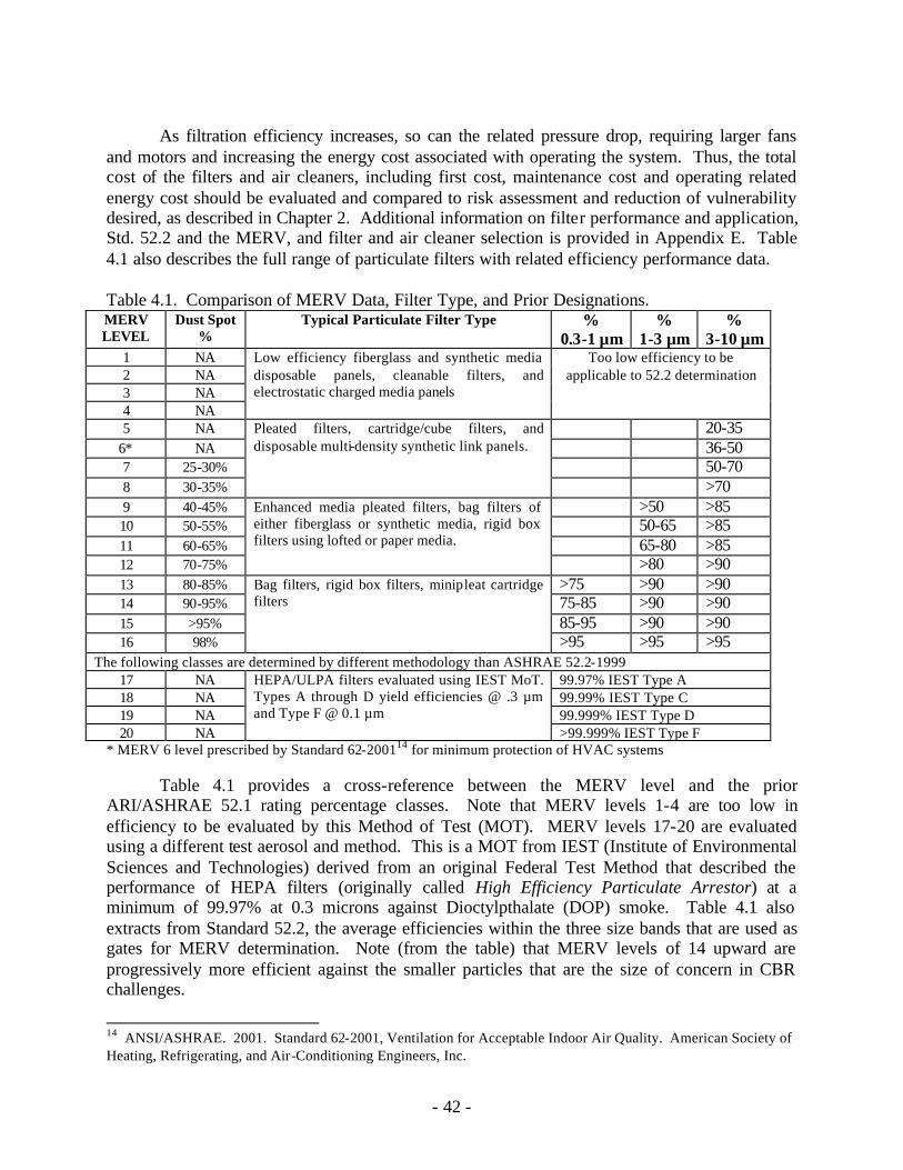
- 42 -
As filtration efficiency increases, so can the related pressure drop, requiring larger fans
and motors and increasing the energy cost associated with operating the system. Thus, the total cost of the filters and air cleaners, including first cost, maintenance cost and operating related energy cost should be evaluated and compared to risk assessment and reduction of vulnerability desired, as described in Chapter 2. Additional information on filter performance and application, Std. 52.2 and the MERV, and filter and air cleaner selection is provided in Appendix E. Table 4.1 also describes the full range of particulate filters with related efficiency performance data.
Table 4.1. Comparison of MERV Data, Filter Type, and Prior Designations. MERV LEVEL
Dust Spot %
Typical Particulate Filter Type % 0.3-1 µm
% 1-3 µm
% 3-10 µm
1 NA 2 NA 3 NA 4 NA
Low efficiency fiberglass and synthetic media disposable panels, cleanable filters, and electrostatic charged media panels
Too low efficiency to be applicable to 52.2 determination
5 NA 20-35 6* NA 36-50 7 25-30% 50-70 8 30-35%
Pleated filters, cartridge/cube filters, and disposable multi-density synthetic link panels.
>70 9 40-45% >50 >85 10 50-55% 50-65 >85 11 60-65% 65-80 >85 12 70-75%
Enhanced media pleated filters, bag filters of either fiberglass or synthetic media, rigid box filters using lofted or paper media.
>80 >90 13 80-85% >75 >90 >90 14 90-95% 75-85 >90 >90 15 >95% 85-95 >90 >90 16 98%
Bag filters, rigid box filters, minipleat cartridge filters
>95 >95 >95 The following classes are determined by different methodology than ASHRAE 52.2-1999
17 NA 99.97% IEST Type A 18 NA 99.99% IEST Type C 19 NA 99.999% IEST Type D 20 NA
HEPA/ULPA filters evaluated using IEST MoT. Types A through D yield efficiencies @ .3 µm and Type F @ 0.1 µm
>99.999% IEST Type F * MERV 6 level prescribed by Standard 62-200114 for minimum protection of HVAC systems
Table 4.1 provides a cross-reference between the MERV level and the prior ARI/ASHRAE 52.1 rating percentage classes. Note that MERV levels 1-4 are too low in efficiency to be evaluated by this Method of Test (MOT). MERV levels 17-20 are evaluated using a different test aerosol and method. This is a MOT from IEST (Institute of Environmental Sciences and Technologies) derived from an original Federal Test Method that described the performance of HEPA filters (originally called High Efficiency Particulate Arrestor) at a minimum of 99.97% at 0.3 microns against Dioctylpthalate (DOP) smoke. Table 4.1 also extracts from Standard 52.2, the average efficiencies within the three size bands that are used as gates for MERV determination. Note (from the table) that MERV levels of 14 upward are progressively more efficient against the smaller particles that are the size of concern in CBR challenges.
14 ANSI/ASHRAE. 2001. Standard 62-2001, Ventilation for Acceptable Indoor Air Quality. American Society of Heating, Refrigerating, and Air-Conditioning Engineers, Inc.
- 43 -
Consideration of air cleaning should also include the need for, and appropriate selection
of, gas and vapor removal technology to reduce the building vulnerability to chemical agents. Evaluation must include whether this can be done with acceptable incremental costs. Fractional or medium efficiency air cleaners are available for application in low to moderate risk situations. Higher efficiency solid bed gas phase cartridges can be applied in higher risk spaces. Total retention CB gas sorbent filters are available that employ specially treated carbon in nuclear type containment devices.
Currently, there is not an established industry standard for testing or rating gas phase filters. However, the performance of these filters is determined by their specific manufacturer using proprietary test methods that can be verified by third party laboratories. All versions of the higher performance gaseous filters represent relatively high cost and require similar space, access, pressure drop, and seal/retainer considerations as the higher end particulate filtration modules. 4.2.7 Compartmentalization and Areas of Refuge
Consideration should be given to the need for additional compartmentalization of larger
buildings both horizontally and vertically, compared to that for fire and life-safety requirements. The compartments should be designed and constructed to provide fire, smoke and particulate separation. This system of compartmentalization, with no cross contamination of return air, can minimize the area of dispersion from the internal release of a biological or radiological agent and provide some short-term protection from the spread of a chemical agent.
Where risk assessments indicate, areas of refuge and decontamination zones may be
considered. Recognizing the realistic impracticability to make buildings “safe,” the issue of “refuge” becomes a key element. For example, areas in buildings such as gymnasiums and auditoriums may be used as temporary areas of refuge if designed for that purpose. 4.2.8 Access to Air Handling Equipment and Ductwork
Access to air distribution equipment and ductwork should be controlled and limited to the
authorized maintenance staff only. All mechanical rooms should be locked and an effective key control system implemented. Access to roof areas and outdoor air intakes should be similarly controlled. Ductwork should be routed and controlled to avoid unauthorized access and preclude the insertion of a biological or chemical agent into the air distribution system.
4.2.9 Single Point for Disconnecting Utilities
Consider providing a single point for disconnecting or shutting-off critical utilities, such
as natural gas and electrical supplies to the building. The shut-off points should be clearly identified and readily available to the first responders to an extraordinary event, but not to intruders.
- 44 -
4.2.10 Locations and Control of Receiving Areas Consideration should be given to locating the delivery and receiving areas, mailrooms
and similar spaces remotely and separately from the primary facilities. However, in some cases these remote locations may not be practical or cost effective. These and other areas within a building, such as lobby and reception areas and loading docks, that are especially subject to the internal release of an agent, should be provided with dedicated outdoor ventilation and exhaust air handling systems, and should be designed and constructed to provide fire, smoke and particulate separation from other spaces. Where possible, these areas should be located on the first floor with a direct emergency exit to the outside.
In some cases, a switch may be made readily available to the occupants to shut off the air
handling system serving the area in case of contamination or release of a suspected agent. However, in these cases, rigorous training must be provided to the accountable occupants to ensure that they are aware of the cond itions when shut off is required verses when fan operation is required, and that unintentional pressure imbalances are not created in adjacent zones. 4.3 HVAC Response and Control Sequences
Integrating the control sequences of HVAC systems for normal and extraordinary periods of operation is a critical design issue. Fundamentally, the issue is one of priority control. Given the variations in extraordinary conditions that can occur, a priority scheme must be determined to change from normal control sequences in order to respond to fire, smoke, floods, seismic, wind, and/or accidental and intentional releases of contaminants. In this Section, some guidance is provided regarding control sequence responses to intentional releases of CBR agents, but the priority of control should be decided, based on the relative risk assessments at the particular facility, as discussed in Chapter 2. 4.3.1 Emergency Systems Shut-down
For buildings without specific CBR protective features, consideration may be given to an alternative control sequence in which the HVAC systems are shut down in response to an attack. If this alternative is chosen, a single tamper-resistant switch to shut off all fans and air handling systems including all outside air fans and louvers and exhaust fans and louvers and to activate an alarm may be considered. This switch should be located in a permanently attended area if possible, and the occupants must be rigorously trained on when and when not to shut down the system. Moreover, this switching alternative must not compromise the requirements of the fire, smoke, and other life-safety requirements of the building. If a single, permanently attended switch location cannot be identified, use of a number of distributed tamper-resistant switch stations may be considered.
If the building has been designed without CBR protective features and with horizontal
and vertical compartments to provide fire, smoke and particulate separation, providing separate switches for shutdown of each compartment may be considered in addition to the overall building switch. However, it should be noted that shutting down the systems as a general
- 45 -
response control strategy, even if the building does not have CBR protective features, could exacerbate exposure to the releases. 4.3.2 Emergency Systems Operations
For a building that has been designed to acceptable vulnerability and level of CBR protection (i.e., see Chapter 2 and Sections 4.1 and 4.2 of this Chapter), the transfer from the normal to response (i.e., emergency) mode of operation will be dependent on both the agent and the point of release.
For an internal release, the HVAC system should respond to a manual or automatic signal
by isolating the zone of release, impeding the CBR agent from directly migrating or being transported to other zones, and removing the agent with the filtration/air cleaning components of the HVAC system. In this case, the response time to maximize the outdoor and exhaust air rates should be considered. Moreover, the response times to pressurize or depressurize the affected zones should be considered. It should be noted that for this response mode to function, a coordinated control sequence is required to close certain dampers and shutdown certain fans while opening other dampers and running other fans. These requirements must be determined on a site-specific basis by the owner and the Licensed Design Professional.
For an external release of a known CBR agent, the HVAC system, if provided with high
performance filtration effective for that agent, should continue to run. When in doubt about the CBR agent or the system efficacy, the system should be shut down. Options that may be considered also include closing the outdoor air dampers that have been directly attacked and opening the outdoor air dampers that have not been attacked in order to maintain the zone pressures. An appropriate alarm/notification system should be activated for all extraordinary modes of operation. 4.3.3 Dampers and Damper Leakage
The shutting off or isolation of air handling or outside air systems is only as effective as the leakage around the dampers. Consideration should be given to minimizing the leakage rates of dampers and damper banks. . 4.4 Protective Action Plans
Plans and drills for responses to extraordinary incidents are essential to the health and
safety of the occupants and first responders. Plans to implement these actions should be addressed and refined during the design phases of the building project.
4.4.1 Plan for Normal Operations A “Normal Operations Plan” should be developed and published. This plan should detail the normal operation of the facility including the intended performance of the HVAC and ventilation systems. The plan should also describe the normal or expected positions of all
- 46 -
operable windows and the normal positions of fire and non-fire doors between zones and compartments.
4.4.2 Plan for Emergency Responses The “Emergency Response Plan,” should include the responsibilities and duties for all occupants and tenants/employees. This plan should be given wide dissemination among the building occupants and tenants/employees to ensure each has a thorough understanding of their duties and responsibilities. This Emergency Response Plan should be developed in coordination with people familiar with the protective measures and other design and construction features of the building. The appropriate operation of the various systems, including the HVAC and outside air systems, alarm and notification systems, building evacuation and similar procedures should be included. The emergency plan should also address the conditions under which the building should be evacuated, and the conditions under which the occupants should remain within the building or move to designated areas within the building. The emergency plan, and the protective measures employed in the building should be consistent with the training and capabilities of the building occupants and tenants/employees.
4.4.3 Public Address System Installation of a public address or similar mass notification system should be considered to inform all building occupants of evacuation or other procedures to be followed in case of an extraordinary incident. The public address system should be zoned in conjunction with the building compartmentalization, so that separate messages can be directed to each zone as appropriate. Stairwell/escape exits must be included in such a public address system.
4.4.4 Emergency Response Drills Full-scale response drills should be held periodically to ensure that the building occupants, tenants/employees, and (and desirably, probable first responders) understand and practice their duties and responsibilities. These drills should include the operation of the appropriate protective features and the building evacuation, movement of occupants to designated areas within the building, or remaining in the building as appropriate for the emergency or threat being simulated. Experience suggests that unless responsibility for the conduct of such drills is assigned to the highest possible level personnel available in each area, full, active participation is unlikely. First responders should be consulted/briefed on how the building is compartmented/zoned, location of designated refuge areas, extraordinary incident response plans and procedures, etc. 4.5 Commissioning and Building Diagnostics
Commissioning, as described in ASHRAE Guideline 1-199615, and as anticipated to be
described in ASHRAE Guideline 0-P16 for Commissioning and Recommissioning, should be an
15 ASHRAE. 1996. Guideline 1-1996 HVAC Commissioning Process. American Society of Heating, Refrigerating, and Air-Conditioning Engineers, Inc. Atlanta.
- 47 -
integral part of the design process for any new or renovation project. However, the ASHRAE Guidelines do not provide specific performance criteria with which to evaluate intended performance during normal or extraordinary conditions. Therefore, the commissioning processes should be augmented by procedures17 that define specific performance criteria as well as measures to demonstrate that the building and its systems are: 1) performing as intended under normal conditions; and 2) prepared to respond to extraordinary incidents in accordance with the accepted level of vulnerability, as determined in the risk assessment, Chapter 2.
4.5.1 Commissioning All measures employed to decrease the building vulnerability, including the proper operation of the HVAC systems under normal operation and extraordinary incidents; the integrity of the building envelope; effectiveness of any advanced filtering systems; and air leakage around dampers, closure devices and filtering stations should be periodically reviewed during construction. The operation and testing of all protective measures should be included and the results documented as part of the building commissioning process. Any deficiencies should be corrected and retested prior to building occupancy. Documentation should ascertain implementation of all preventive maintenance procedures and recommendations, the proper operation of all protective measures under both normal and extraordinary conditions, and recommendations on the periodic retesting and maintenance of each protective feature. The Testing, Adjusting, and Balancing (TAB) report should demonstrate adherence to design intent including maintenance of specified pressure differentials between adjacent zones and compartments. 4.5.2 Recommissioning All features should be periodically operated and tested to ensure that they are available and functioning as intended in case of an extraordinary incident. All recommended preventive maintenance activities should be performed as specified. In addition, these systems should be recommissioned on a regular basis. This should include testing the integrity of the building envelope, testing and cleaning or replacing filter media as needed, measuring the bypass air around filters and adsorbers, ensuring the tight close off of dampers and closure devices, and ensuring performance of the control sequences during normal and simulated extraordinary conditions. Any deficiencies should be noted and corrected.
16 ASHRAE. 2002. Guideline 0-P. The Commissioning Process. (Unpublished Public Review Document, April 2002). American Society of Heating, Refrigerating, and Air-Conditioning Engineers, Inc. Atlanta. 17 Woods, J.E. 2001. What is Productivity and How is it Measured? In: Productivity and the Workplace. GSA Office of Governmentwide Policy. December 2001, pp. 33-40.

- 49 -
5.0 GUIDANCE AND RECOMMENDATIONS FOR EXISTING BUILDINGS
The objective of this Chapter is to consider some methods that can be effectively
employed during operations of existing buildings to meet the risk management strategy established by methods in Chapter 2. In Section 5.1 issues are addressed regarding the operational and maintenance modifications that can be employed to achieve acceptable levels of vulnerability in existing buildings. Section 5.2 considers additional reductions in vulnerability that can be achieved through incremental retrofits and upgrades that are to be employed for other energy management or environmental control reasons. 5.1 Operational and Maintenance Issues
As discussed in Appendix B, approximately 4.7 million buildings currently exist in the U.S. that fall within the scope of the issues addressed in this Report. As a first step, the functional condition of the existing building, the intended design, and the mitigation intents should be analyzed. Clearly, not all of these buildings will reveal sufficiently high risk of intentional attack to justify significant expenditures for vulnerability reductions. However, some of the buildings do have elevated risk of CBR attacks and have known problems of performance during normal conditions that would affect the ability to respond to CBR attacks. These problems should be corrected. Risk assessments of properties should be conducted, using procedures such as those described in Section 2.4.1. Based on the results of the risk assessments, risk treatment procedures, similar to those in Section 2.4.2, should be initiated to reduce the vulnerabilities. Recommissioning with emphasis on operation and maintenance instructions should be implemented. .
5.2 Retrofit and Upgrade Issues
In the stock of existing buildings, the vast majority will be retrofit with updated “utility” systems at some time. These systems include virtually each and every component of the building except the basic structure. The driving forces for these retrofit activities include changing needs of society, changing customs, energy economics, and technology.
Chapter 4 provided a number of recommendations for the design, construction and operation and maintenance of new buildings, from low cost measures that should be considered for essentially all new facilities such as more efficient air filtering, to other, more complex, protective measures that may have limited application and would have a significant impact on first costs, operating and maintenance costs, and energy costs. These options may also be applicable to building renovation and retrofit based on the risk, and on the acceptable level of building vulnerability. Each of these options should be considered and implemented as appropriate and applicable in retrofit projects. However, with existing buildings some of the options may need to be revised and alternatives selected that will provide a similar reduction in vulnerability while meeting the economic and building features associated with renovations.
- 50 -
5.2.1 Building Envelopes Modifications to building envelopes are one of the major concerns of building retrofit programs. Reasons for this include 1) the envelope “ages”; 2) in warm humid climates a tight, properly designed envelope is paramount to prevent mold and mildew; 3) in cold or hot dry climates a good thermal envelope is beneficial to interior thermal comfort; and 4) in most climates a good thermal envelope is beneficial to energy conservation. A building envelope that meets these needs should also provide some reduction in vulnerability to extraordinary incidents. Testing the integrity or “air tightness” of the envelope should help ensure that the new or renovated building envelope will provide a good thermal and acoustic barrier. If the existing building envelope is to be retained, testing the building envelope for air tightness and sealing to eliminate air leakage may be readily justified based on energy savings and comfort. In either case, a tight building envelope with minimum air leakage will be beneficial in reducing contamination from an external source. 5.2.2 HVAC Systems HVAC systems provide the thermal environment for comfort, health and productivity of the occupants. Major revisions or replacement of the HVAC systems are often a major element of a retrofit project. Nothing should be done in the interest of “reducing building vulnerability” that reduces the air quality or comfort and health of the building environment under normal operating conditions. However, good design practice should result in improved air quality, comfort, and health, while reducing energy costs and improving safety.
5.2.2.1 Filtration and Air Cleaning
Increasing filter efficiencies will provide some reduction in building vulnerability to biological and radiological particulate agents. The system should be evaluated to determine the maximum filter efficiency that can be economically and physically achieved. When indicated by risk assessment, particulate filters with a MERV rating of 14 or higher should be considered. The addition of HEPA filters or HEPA filtration with gas adsorbers will normally require revisions in the air distribution system, increase the space requirements for system installation and maintenance, and result in a significant increase in operation, maintenance and energy costs, see Section 4.2.1.6 and Appendix E for additional details.
5.2.2.2 Outdoor Air Intakes If susceptible to attack, outdoor air intakes should be relocated so that they are protected
from external sources of contamination. Where economics, building or system configurations or similar issues preclude the relocation or installation of outside air intakes on the roof, they should be located away from publicly accessible areas and protected by screens, walls or other means to minimize unauthorized access and prevent the insertion of a canister or similar container into the ventilation system. Obstructions that could conceal a device should be minimized, and the use of surveillance camera and/or security intrusion alarm sensors should be considered.
- 51 -
5.2.2.3 Testing, Adjusting, and Balancing (TAB) When replacing or modifying the HVAC system ensure a balance between the
introduction of outside air and exhaust air to maintain the pressure relationships within the building
5.2.3 Functional Isolation or Relocation
As part of a building retrofit, the mail room, delivery-receiving areas, reception areas, and other areas with a high risk of internal contamination should be considered for relocation to the perimeter of the first floor and provided with an emergency exit directly to the outside. Regardless of location, these spaces can be provided with dedicated. HVAC systems and be provided with fire, smoke and particulate separation from other areas, see Sections 3.11, 3.12, and 4.2.1.10.

- 53 -
6.0 REFERENCES Stone, Gary K. Fundamentals of Financial Planning Second Edition. The American College./Bryn Mawr,
Pennsylvania 1993 Mehr, Robert I. And Hedges, Bob A. Risk Management Concepts and Applications. Richard D. Irwin,
Inc. Homewood, Illinois. 1973. The National Academies. Making the Nation Safer: The Role of Science and Technology in Countering
Terriorism. The National Academy Press. Washington, D.C. 2002. Willhite, Anne Marie and Norton, Darcy R. “Establish A Baseline Assessment to Manage Risks Using
Risk Matrix.” August 21, 2002. http:// www.mitre.org/resources/centers/sepo/risk Willhite, Anne Marie and Norton, Darcy R. “An Overview of the ESC Risk Management Process.”
September 24, 2002. http:// www.mitre.org/resources/centers/sepo/risk Engert, Pamelia A. and Lunsdowns, Zachary F. “Risk Matrix User’s Guide.” September 24, 2002. http://
www.mitre.org/resources/centers/sepo/risk/pdf/risk_users_guide.pdf. McNab, W. Bruce. “Basic Principles of Risk Management and Decision Analysis” “Risk Assessment Do’s and Don’ts.” August 21, 2002. http://www.jebcl.com/riskdo/riskdo.htm. “Combining Risk Factor Assessments.” August 21, 2002. http://www.jebcl.com/riskdo/riskdo4.htm. “Pairwise Comparison – The Analytic Hierarchy Process.” August 21, 2002.
http://www.jebcl.com/riskdo/riskdo3.htm. “The Benefits of: Security Risk Analysis.” August 21, 2002. http://eon-
commerce.com/riskanalysis/benefits.htm. “A Proven Solution for: Security Risk Analysis” August 21, 2002. http://eon-
commerce.com/riskanalysis/solution.htm. “Risk Management Frequently Asked Questions.” August 21, 2002.
http://sei.cmu.edu/organizations/programs/sepm/risk/risk.faq.html. “Risk Management Overview.” August 21, 2002. http://sei.cmu.edu/programs/sepm/risk/index.html. “DOE’s Principles for Using Risk Analysis.” EM - U.S. Department of Energy - Office of Environmental
Management. August 21, 2002. http://www.em.doe.gov/irm/principl.html. “SORM: State Office of Risk Management.” Volume I. Service to State Of Texas Agencies and
Employees. September 15, 2002. http://www.sorm.state.tx.us. “Five Steps to risk assessment.” Health and Safety Education. August 21, 2002.
http://www.hsebooks.co.uk. “RAIS: What is RA?” August 21, 2002. http://risk.lsd.ornl.gov/minicours/rap_q1.stml.
- 54 -
Parachini, John V. “Combating Terrorism: Assessing Threats, Risk Management, and Establishing Priorities.” September 24, 2002. http://cns.miis.edu/pugs/reports/paraterr.htm.
ASHRAE. 2002. Guideline 0-P. The Commissioning Process. (Unpublished Public Review Document,
April 2002). American Society of Heating, Refrigerating, and Air-Conditioning Engineers, Inc. Atlanta.
NIBS. 2002. Physical Security Assessment for Department of Veterans Affairs Facilities:
Recommendations of the National Institute of Building Sciences Task Group to the Department of Veterans Affairs, September 2002.
Woods, J.E. 2001. What is Productivity and How is it Measured? In: Productivity and the Workplace.
GSA Office of Governmentwide Policy. December 2001, pp. 33-40. CBECS. 2002. Commercial Building Energy Consumption Survey. U.S., Department of Energy, Washington, D.C. RECS. 2002. Residential Energy Consumption Survey. U.S., Department of Energy, Washington, D.C. AIA. 2001. Building Security through Design. The American Institute of Architects, Washington, D.C. Bonforte, G. 1979. Conversion of Unventilated, Longitudinally or Semi-Transverse Ventilated Vehicular
Rock Bore Tunnels to Fully Transverse Mechanical Ventilation System. In: Proceedings of Third International Symposium on the Aerodynamics and Ventilation of Vehicle Tunnels.
USPS. 2001. Mail Center Security Handbook, U.S. Postal Service,
www.usps.com/news/2001/press/pr_011022gsa. ANSI/ASHRAE. 1999. Standard 52.5: Method of Testing General Ventilation Air-Cleaning Devices fro
Removal Efficiency by Particle Size. American Society of Heating, Refrigerating, and Air-Conditioning Engineers, Inc. Atlanta.
ANSI/ASHRAE. 2001. Standard 62-2001: Ventilation for Acceptable Indoor Air Quality. American Society of Heating, Refrigerating, and Air-Conditioning Engineers, Inc. Garvey PF, Lansdowne ZF. 2002. Risk Matrix : An Approach for Identifying, Assessing, and Ranking Program Risk . http://mitre.org/resources/center/sepo/risk/pdf/af_journal_logistics.pdf.

- 55 -
APPENDICES

- 57 -
Appendix A: Members of ASHRAE Presidential Ad Hoc Committee James E Woods, Building Diagnostics Research Institute, Chairman * Dwight A Beranek, Hq USA Corps Of Engineers Harvey Brickman, Tishman Realty & Construction Co.* H E Burroughs, Building Wellness Consultancy, Inc * William J Coad, Coad Engineering Consulting * D Scott Fisher, State Farm Insurance Co George O Glavis, US Dept Of State * Ralph F Goldman, Comfort Technology * Andrew K Persily, National Inst. Of Standards & Tech * Lawrence G Spielvogel, Lawrence G Spielvogel Inc Bob Thompson, US EPA * Ronald P Vallort, Ron Vallort and Associates Martin Joseph Weiland, ASHRAE * * Member of 2001-02 ASHRAE Presidential Study Group on Health and Safety Under Extraordinary Incidents

- 59 -
Appendix B: Building Demographics
Commercial buildings are highly variable in size, age, function and usage, HVAC system
type, and owner-operator-occupant relationships. Many of these attributes impact their vulnerability to extraordinary incidents, as well as the implementation of options for responding to such incidents. To characterize these attributes demographically, data from the U.S. Department of Energy’s Energy Information Administration Commercial Building Energy Consumption Survey (CBECS) (DOE EIA 2002) are reviewed.18 This survey contains data gathered in 1999. Presumably similar surveys are available for other countries, but this ad hoc Committee is not aware of surveys of the commercial building stock on an international scale. The population for the 2002 CBECS consisted of all “commercial” buildings in the United States with more than 1,000 square feet of floor space. The commercial building stock, as defined by CBECS, includes service businesses, such as retail and wholesale stores, hotels and motels, restaurants, and hospitals, as well as a wide range of facilities that would not be considered “commercial” in a traditional economic sense, such as public schools, correctional institutions, religious, and fraternal organizations. The CBECS excludes the goods-producing industries: manufacturing, agriculture, mining, forestry and fisheries, and construction. It also does not include single or multifamily residential buildings of less than four units, which are covered in another similar publication19. B.1 Number and Size Distribution In 1999, there were 4.7 million commercial buildings in the United States comprising 67.3 billion square feet of floor space. That amount of commercial floor space exceeds the total area of the State of Delaware and amounts to more than 200 square feet for every resident in the United States. The vast majority of buildings were in the smallest size categories, with half (50%) in the smallest category (1,001 to 5,000 square feet) and three-quarters in the two smallest categories (1,001 to 10,000 square feet). About 5% of buildings were larger than 50,000 square feet and less than 2% were larger than 100,000 square feet. However, the distribution of building floor area is quite different from the distribution of building occupants among buildings of different sizes. Almost one third of all workers are in buildings larger than 100,000 square feet, while about one quarter are in buildings 10,000 square feet or less. Federal, state, and local governments own 11% of all commercial buildings and 18% of the total floor space. B.2 Age Distribution
Most commercial buildings are expected to last for decades. And while each year new buildings are constructed and older buildings are demolished at a rate of approximately 2% per year, the commercial buildings stock is dominated by older buildings. The median age of commercial buildings in 1999 was 30.5 years. About two thirds of buildings and total floor space in 1999 were constructed before 1980, and almost half of all commercial buildings, and floor space, were constructed before 1970, especially the small retail, office/warehouse, and
18 CBECS. 2002. Commercial Building Energy Consumption Survey. U.S., Department of Energy, Washington, D.C. 19 RECS. 2002. Residential Energy Consumption Survey. U.S., Department of Energy, Washington, D.C.
- 60 -
educational facilities. Many modern high-profile high-rise buildings and commercial enterprises in US urban centers are now decades old. This aging building population will experience deteriorating system performance and energy efficiency without rigorous and sustained maintenance. The building population also spans the entire development cycle of modern air conditioning and represents a myriad of equipment styles, brands, and system types. The newer buildings are more likely to have been built to more demanding energy performance standards and include more complex air distribution schemes, such as variable air volume control and demand ventilation. The newer facilities are also more likely to have more elaborate equipment management controls and protocols, such as automated building control systems (BAS). B.3 Function and Use Distribution Five types of building activity—mercantile, service, office, warehouse and storage, and education comprised 67% of commercial floor space and 60% of the total number of commercial buildings in 1999. Mercantile and service buildings were by far the most numerous types (about 25%), but they were not as dominant in floor space (20%). Comparison of the percentage of floor space and buildings for a given category gives an indication of the mean, or average, size of buildings in the category. For example, education buildings accounted for 13% of total floor space and 7% of total number buildings; i.e., those buildings were larger than average in size. At 26,500 square feet per building, education buildings were among the largest types of commercial building, much larger than the average of all commercial buildings (14,500 square feet per building). Two other activities, lodging and health care (29,500 and 23,000 square feet per building, respectively), had buildings that were also larger than average. B.4 HVAC Equipment Distribution Just as there is a tremendous range in the U.S. commercial building stock, there is also great variety in the equipment used to heat, cool, and ventilate these buildings and to distribute air associated with space conditioning and ventilation. For fairly obvious reasons, small and large buildings cannot be heated or cooled effectively with the same types of equipment. Therefore, smaller and larger buildings exhibit important differences in heating, cooling, and ventilating equipment. For instance, residential-type window air conditioning units or split systems are quite satisfactory for cooling many small commercial buildings. However, large office buildings require much more complex integrated heating, cooling, and distribution systems.
Two types of heating equipment show significant differences by the age of buildings. Boilers are used most widely in older buildings, while packaged heating units are used most widely in more recently constructed buildings. The four predominant types of heating equipment have the heat they produce distributed primarily via one of three types of heating distribution systems: warm air produced by packaged units and furnaces is distributed primarily by ducts or air handling units; hot water or steam generated by boilers is transported to radiators or baseboards; and individual space heaters give off heat directly to surrounding areas without a separate distribution system.
Packaged air-conditioning units were by far the most widely used types of cooling equipment, both as the main equipment used and for total use. They cooled 54% of cooled floor
- 61 -
space and 42% of cooled buildings. Central chillers were used to cool about 19% of cooled floor space, but only 3% of buildings, while individual (window or wall) air-conditioning units, residential-type central air-conditioning, and heat pumps were used for a much larger percentage of cooled floor space.
Particular types of cooling equipment show significant differences in use by building size. Residential type central air conditioning units show relatively greater use in the smallest buildings. Central chillers are used primarily in the largest buildings, and cooled 64% of the floor space in the largest buildings, but only 14% in the middle category (buildings 10,001 to 200,000 square feet). The age of the building was less of a factor for type of cooling equipment than for type of heating equipment. Only buildings that used individual (window or wall) air conditioning units showed a significant relationship between equipment prevalence and building age, those units are much more common in buildings constructed before 1960 than in buildings constructed after 1989. They cooled about one-third of the cooled floor space in older pre-1960 buildings, compared to only 13% in buildings constructed in the 1990’s. Packaged air conditioning units, residential type central air conditioners, and cold air produced by central chillers had the cool air distributed primarily by ducts or air-handling units. Central chillers that produced chilled water had cool air distributed via the use of fan- coil units. Individual air conditioning units cooled air directly (with out a separate system) in the room or area where they were located. Building demography also reflects the advances of filtration throughout the last three quarters century, and existing HVAC systems demonstrate most of the filter configurations that have been created and installed over that time. This trend includes early disposable panels, roll/blanket media, electrostatic precipitators, and more recently, various extended media filters. The most commonly used filter in current buildings is an upgraded 2” panel filter. This type of filter is also used in a prefilter mode for extended media cartridges of higher efficiencies, which are used in high-end commercia l and institutional buildings, laboratories, and healthcare facilities. Most commercial unitary air conditioning equipment, such as roof top units, currently employ the 2” filters that have a MERV 5 to 8 efficiency performance.

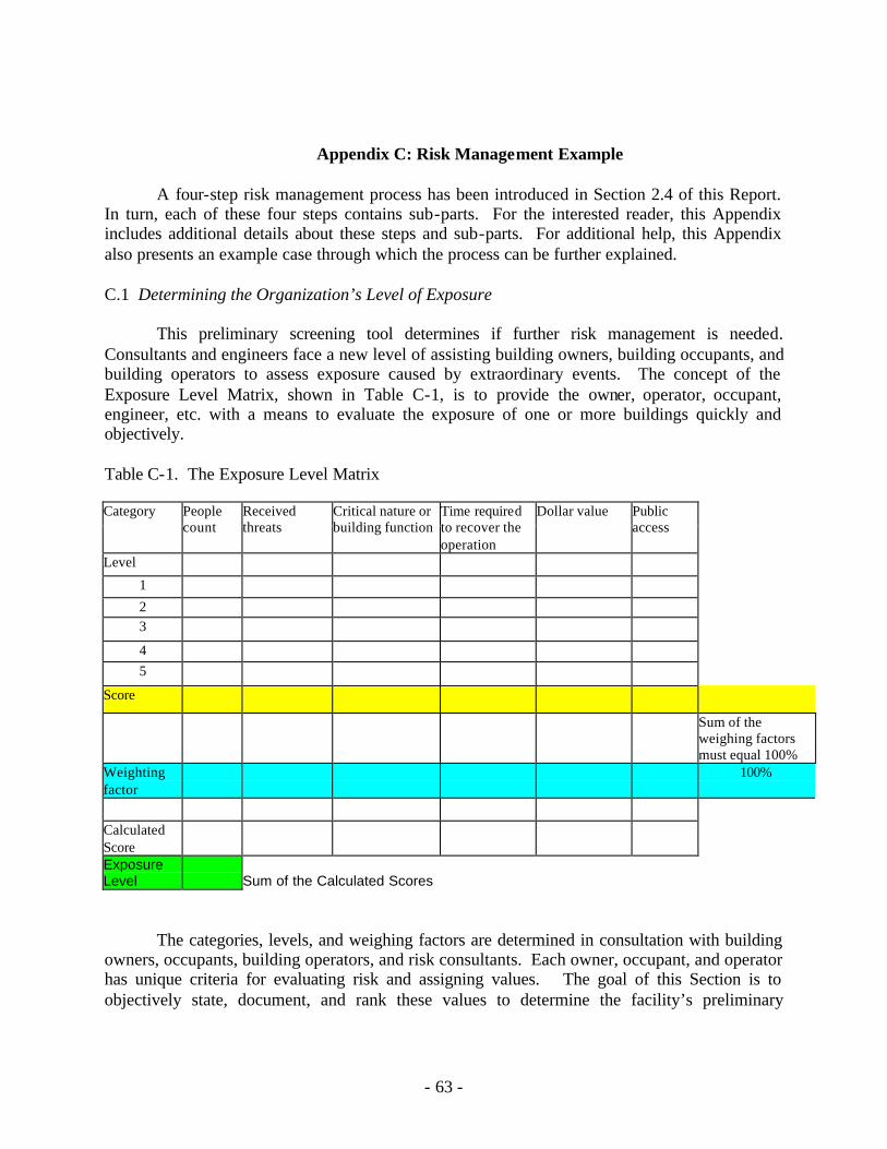
- 63 -
Appendix C: Risk Management Example
A four-step risk management process has been introduced in Section 2.4 of this Report. In turn, each of these four steps contains sub-parts. For the interested reader, this Appendix includes additional details about these steps and sub-parts. For additional help, this Appendix also presents an example case through which the process can be further explained. C.1 Determining the Organization’s Level of Exposure
This preliminary screening tool determines if further risk management is needed.
Consultants and engineers face a new level of assisting building owners, building occupants, and building operators to assess exposure caused by extraordinary events. The concept of the Exposure Level Matrix, shown in Table C-1, is to provide the owner, operator, occupant, engineer, etc. with a means to evaluate the exposure of one or more buildings quickly and objectively.
Table C-1. The Exposure Level Matrix
Category People count
Received threats
Critical nature or building function
Time required to recover the operation
Dollar value Public access
Level
1
2 3
4 5
Score
Sum of the weighing factors must equal 100%
Weighting factor
100%
Calculated Score Exposure Level
Sum of the Calculated Scores
The categories, levels, and weighing factors are determined in consultation with building owners, occupants, building operators, and risk consultants. Each owner, occupant, and operator has unique criteria for evaluating risk and assigning values. The goal of this Section is to objectively state, document, and rank these values to determine the facility’s preliminary
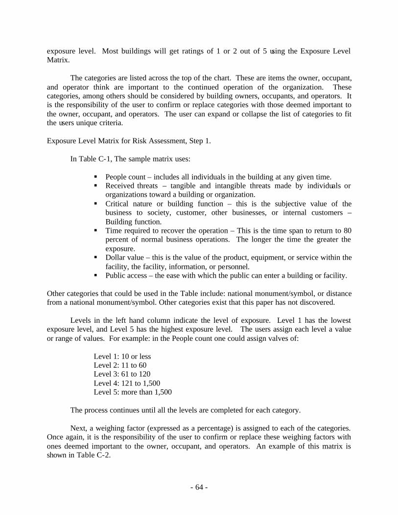
- 64 -
exposure level. Most buildings will get ratings of 1 or 2 out of 5 using the Exposure Level Matrix.
The categories are listed across the top of the chart. These are items the owner, occupant, and operator think are important to the continued operation of the organization. These categories, among others should be considered by building owners, occupants, and operators. It is the responsibility of the user to confirm or replace categories with those deemed important to the owner, occupant, and operators. The user can expand or collapse the list of categories to fit the users unique criteria.
Exposure Level Matrix for Risk Assessment, Step 1.
In Table C-1, The sample matrix uses:
§ People count – includes all individuals in the building at any given time. § Received threats – tangible and intangible threats made by individuals or
organizations toward a building or organization. § Critical nature or building function – this is the subjective value of the
business to society, customer, other businesses, or internal customers – Building function.
§ Time required to recover the operation – This is the time span to return to 80 percent of normal business operations. The longer the time the greater the exposure.
§ Dollar value – this is the value of the product, equipment, or service within the facility, the facility, information, or personnel.
§ Public access – the ease with which the public can enter a building or facility.
Other categories that could be used in the Table include: national monument/symbol, or distance from a national monument/symbol. Other categories exist that this paper has not discovered.
Levels in the left hand column indicate the level of exposure. Level 1 has the lowest exposure level, and Level 5 has the highest exposure level. The users assign each level a value or range of values. For example: in the People count one could assign valves of:
Level 1: 10 or less Level 2: 11 to 60 Level 3: 61 to 120 Level 4: 121 to 1,500 Level 5: more than 1,500
The process continues until all the levels are completed for each category.
Next, a weighing factor (expressed as a percentage) is assigned to each of the categories.
Once again, it is the responsibility of the user to confirm or replace these weighing factors with ones deemed important to the owner, occupant, and operators. An example of this matrix is shown in Table C-2.
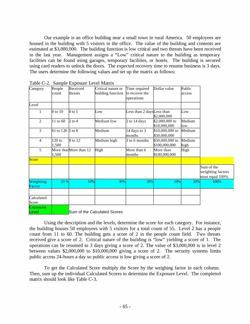
- 65 -
Our example is an office building near a small town in rural America. 50 employees are
housed in the building with 5 visitors in the office. The value of the building and contents are estimated at $3,000,000. The building function is low critical and two threats have been received in the last year. Management assigns a “Low” critical nature to the building as temporary facilities can be found using garages, temporary facilities, or hotels. The building is secured using card readers to unlock the doors. The expected recovery time to resume business is 3 days. The users determine the following values and set up the matrix as follows: Table C-2. Sample Exposure Level Matrix
Received threats
Category People count
Critical nature or building function
Time required to recover the operations
Dollar value Public access
Level
1 0 to 10 0 to 1 Low Less than 2 daysLess than $2,000,000
Low
2 11 to 60 2 to 4 Medium low 2 to 14 days $2,000,000 to $10,000,000
Medium low
3 61 to 120 5 to 8 Medium 14 days to 3 months
$10,000,000 to $50,000,000
Medium
4 120 to 1,500
9 to 12 Medium high 3 to 6 months $50,000,000 to $100,000,000
Medium high
5 More than 1,500
More than 12 High More than 6 months
More than $100,000,000
High
Score
Sum of the weighting factors must equal 100%
Weighting Factor
20 % 10% 30% 10% 10% 20% 100%
Calculated Score Exposure Level
Sum of the Calculated Scores
Using the description and the levels, determine the score for each category. For instance,
the building houses 50 employees with 5 visitors for a total count of 55. Level 2 has a people count from 11 to 60. The building gets a score of 2 in the people count field. Two threats received give a score of 2. Critical nature of the building is “low” yielding a score of 1. The operations can be resumed in 3 days giving a score of 2. The value of $3,000,000 is in level 2 between values $2,000,000 to $10,000,000 giving a score of 2. The security systems limits public access 24-hours a day so public access is low giving a score of 2.
To get the Calculated Score multiply the Score by the weighing factor in each column.
Then, sum up the individual Calculated Scores to determine the Exposure Level. The completed matrix should look like Table C-3.
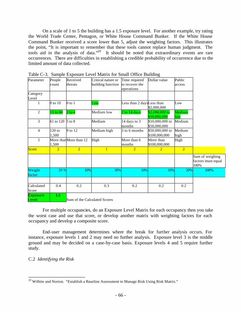
- 66 -
On a scale of 1 to 5 the building has a 1.5 exposure level. For another example, try rating the World Trade Center, Pentagon, or White House Command Bunker. If the White House Command Bunker received a score lower than 5, adjust the weighting factors. This illustrates the point, “It is important to remember that these tools cannot replace human judgment. The tools aid in the analysis of data.”20 It should be noted that extraordinary events are rare occurrences. There are difficulties in establishing a credible probability of occurrence due to the limited amount of data collected. Table C-3. Sample Exposure Level Matrix for Small Office Building
Parameter People count
Received threats
Critical nature or building function
Time required to recover the operations
Dollar value Public access
Category Level
1 0 to 10 0 to 1 Low Less than 2 daysLess than $2,000,000
Low
2 11 to 60 2 to 4 Medium low 2 to 14 days $2,000,000 to $10,000,000
Medium low
3 61 to 120 5 to 8 Medium 14 days to 3 months
$10,000,000 to $50,000,000
Medium
4 120 to 1,500
9 to 12 Medium high 3 to 6 months $50,000,000 to $100,000,000
Medium high
5 More than 1,500
More than 12 High More than 6 months
More than $100,000,000
High
Score 2 2 1 2 2 2
Sum of weighing factors must equal 100%
Weight factor
20 % 10% 30% 10% 10% 20% 100%
Calculated Score
0.4 0.2 0.3 0.2 0.2 0.2
Exposure Level
1.5 Sum of the Calculated Scores
For multiple occupancies, do an Exposure Level Matrix for each occupancy then you take
the worst case and use that score, or develop another matrix with weighting factors for each occupancy and develop a composite score.
End-user management determines where the break for further analysis occurs. For instance, exposure levels 1 and 2 may need no further analysis. Exposure level 3 is the middle ground and may be decided on a case-by-case basis. Exposure levels 4 and 5 require further study. C.2 Identifying the Risk
20 Wilhite and Norton. “Establish a Baseline Assessment to Manage Risk Using Risk Matrix.”
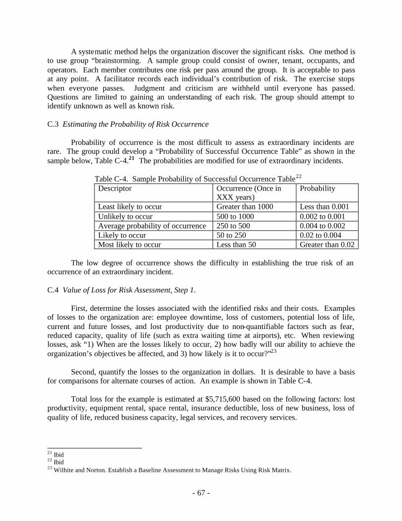
- 67 -
A systematic method helps the organization discover the significant risks. One method is to use group “brainstorming. A sample group could consist of owner, tenant, occupants, and operators. Each member contributes one risk per pass around the group. It is acceptable to pass at any point. A facilitator records each individual’s contribution of risk. The exercise stops when everyone passes. Judgment and criticism are withheld until everyone has passed. Questions are limited to gaining an understanding of each risk. The group should attempt to identify unknown as well as known risk. C.3 Estimating the Probability of Risk Occurrence
Probability of occurrence is the most difficult to assess as extraordinary incidents are rare. The group could develop a “Probability of Successful Occurrence Table” as shown in the sample below, Table C-4.21 The probabilities are modified for use of extraordinary incidents.
Table C-4. Sample Probability of Successful Occurrence Table22 Descriptor Occurrence (Once in
XXX years) Probability
Least likely to occur Greater than 1000 Less than 0.001 Unlikely to occur 500 to 1000 0.002 to 0.001 Average probability of occurrence 250 to 500 0.004 to 0.002 Likely to occur 50 to 250 0.02 to 0.004 Most likely to occur Less than 50 Greater than 0.02
The low degree of occurrence shows the difficulty in establishing the true risk of an
occurrence of an extraordinary incident. C.4 Value of Loss for Risk Assessment, Step 1.
First, determine the losses associated with the identified risks and their costs. Examples of losses to the organization are: employee downtime, loss of customers, potential loss of life, current and future losses, and lost productivity due to non-quantifiable factors such as fear, reduced capacity, quality of life (such as extra waiting time at airports), etc. When reviewing losses, ask “1) When are the losses likely to occur, 2) how badly will our ability to achieve the organization’s objectives be affected, and 3) how likely is it to occur?”23
Second, quantify the losses to the organization in dollars. It is desirable to have a basis for comparisons for alternate courses of action. An example is shown in Table C-4.
Total loss for the example is estimated at $5,715,600 based on the following factors: lost
productivity, equipment rental, space rental, insurance deductible, loss of new business, loss of quality of life, reduced business capacity, legal services, and recovery services.
21 Ibid 22 Ibid 23 Wilhite and Norton. Establish a Baseline Assessment to Manage Risks Using Risk Matrix.
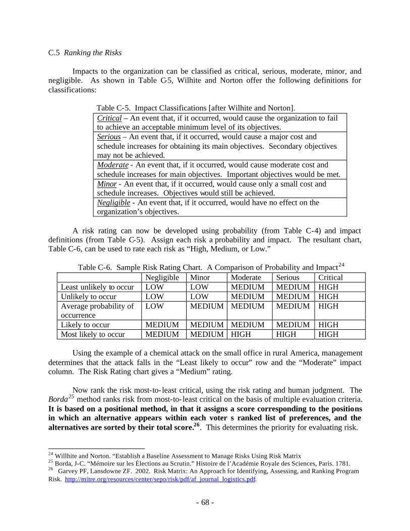
- 68 -
C.5 Ranking the Risks
Impacts to the organization can be classified as critical, serious, moderate, minor, and negligible. As shown in Table C-5, Wilhite and Norton offer the following definitions for classifications:
Table C-5. Impact Classifications [after Wilhite and Norton]. Critical – An event that, if it occurred, would cause the organization to fail to achieve an acceptable minimum level of its objectives. Serious – An event that, if it occurred, would cause a major cost and schedule increases for obtaining its main objectives. Secondary objectives may not be achieved. Moderate - An event that, if it occurred, would cause moderate cost and schedule increases for main objectives. Important objectives would be met. Minor - An event that, if it occurred, would cause only a small cost and schedule increases. Objectives would still be achieved. Negligible - An event that, if it occurred, would have no effect on the organization’s objectives.
A risk rating can now be developed using probability (from Table C-4) and impact
definitions (from Table C-5). Assign each risk a probability and impact. The resultant chart, Table C-6, can be used to rate each risk as “High, Medium, or Low.”
Table C-6. Sample Risk Rating Chart. A Comparison of Probability and Impact24 Negligible Minor Moderate Serious Critical Least unlikely to occur LOW LOW MEDIUM MEDIUM HIGH Unlikely to occur LOW LOW MEDIUM MEDIUM HIGH Average probability of occurrence
LOW MEDIUM MEDIUM MEDIUM HIGH
Likely to occur MEDIUM MEDIUM MEDIUM MEDIUM HIGH Most likely to occur MEDIUM MEDIUM HIGH HIGH HIGH
Using the example of a chemical attack on the small office in rural America, management
determines that the attack falls in the “Least likely to occur” row and the “Moderate” impact column. The Risk Rating chart gives a “Medium” rating.
Now rank the risk most-to- least critical, using the risk rating and human judgment. The
Borda25 method ranks risk from most-to- least critical on the basis of multiple evaluation criteria. It is based on a positional method, in that it assigns a score corresponding to the positions in which an alternative appears within each voter s ranked list of preferences, and the alternatives are sorted by their total score.26. This determines the priority for evaluating risk.
24 Willhite and Norton. “Establish a Baseline Assessment to Manage Risks Using Risk Matrix 25 Borda, J-C. “Mémoire sur les Élections au Scrutin.” Histoire de l’Académie Royale des Sciences, Paris. 1781. 26 Garvey PF, Lansdowne ZF. 2002. Risk Matrix: An Approach for Identifying, Assessing, and Ranking Program Risk. http://mitre.org/resources/center/sepo/risk/pdf/af_journal_logistics.pdf.
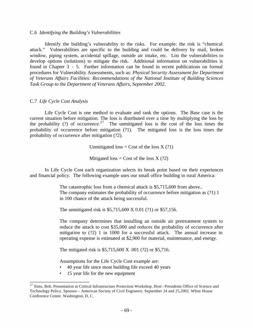
- 69 -
C.6 Identifying the Building’s Vulnerabilities Identify the building’s vulnerability to the risks. For example: the risk is “chemical
attack.” Vulnerabilities are specific to the building and could be delivery by mail, broken window, piping system, accidental spillage, outside air intake, etc. List the vulnerabilities to develop options (solutions) to mitigate the risk. Additional information on vulnerabilities is found in Chapter 3 - 5. Further information can be found in recent publications on formal procedures for Vulnerability Assessments, such as: Physical Security Assessment for Department of Veterans Affairs Facilities: Recommendations of the National Institute of Building Sciences Task Group to the Department of Veterans Affairs, September 2002.
C.7 Life Cycle Cost Analysis
Life Cycle Cost is one method to evaluate and rank the options. The Base case is the current situation before mitigation. The loss is distributed over a time by multiplying the loss by the probability (?) of occurrence.27 The unmitigated loss is the cost of the loss times the probability of occurrence before mitigation (?1). The mitigated loss is the loss times the probability of occurrence after mitigation (?2).
Unmitigated loss = Cost of the loss X (?1)
Mitigated loss = Cost of the loss X (?2)
In Life Cycle Cost each organization selects its break point based on their experiences and financial policy. The following example uses our small office building in rural America:
The catastrophic loss from a chemical attack is $5,715,600 from above.. The company estimates the probability of occurrence before mitigation as (?1) 1 in 100 chance of the attack being successful. The unmitigated risk is $5,715,600 X 0.01 (?1) or $57,156. The company determines that installing an outside air pretreatment system to reduce the attack to cost $35,000 and reduces the probability of occurrence after mitigation to (?2) 1 in 1000 for a successful attack. The annual increase in operating expense is estimated at $2,900 for material, maintenance, and energy. The mitigated risk is $5,715,600 X .001 (?2) or $5,716. Assumptions for the Life Cycle Cost example are: • 40 year life since most building life exceed 40 years • 15 year life for the new equipment
27 Sims, Bob. Presentation at Critical Infrastructure Protection Workshop. Host - Presidents Office of Science and Technology Policy. Sponsor – American Society of Civil Engineers. September 24 and 25,2002. White House Conference Center. Washington, D, C.
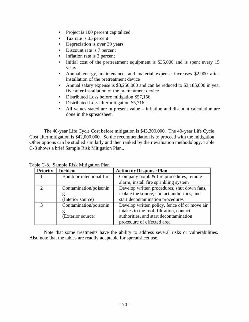
- 70 -
• Project is 100 percent capitalized • Tax rate is 35 percent • Depreciation is over 39 years • Discount rate is 7 percent • Inflation rate is 3 percent • Initial cost of the pretreatment equipment is $35,000 and is spent every 15
years • Annual energy, maintenance, and material expense increases $2,900 after
installation of the pretreatment device • Annual salary expense is $3,250,000 and can be reduced to $3,185,000 in year
five after installation of the pretreatment device • Distributed Loss before mitigation $57,156 • Distributed Loss after mitigation $5,716 • All values stated are in present value – inflation and discount calculation are
done in the spreadsheet.
The 40-year Life Cycle Cost before mitigation is $43,300,000. The 40-year Life Cycle Cost after mitigation is $42,000,000. So the recommendation is to proceed with the mitigation. Other options can be studied similarly and then ranked by their evaluation methodology. Table C-8 shows a brief Sample Risk Mitigation Plan.. Table C-8. Sample Risk Mitigation Plan
Priority Incident Action or Response Plan 1 Bomb or intentional fire Company bomb & fire procedures, remote
alarm, install fire sprinkling system 2 Contamination/poisonin
g (Interior source)
Develop written procedures, shut down fans, isolate the source, contact authorities, and start decontamination procedures
3 Contamination/poisoning (Exterior source)
Develop written policy, fence off or move air intakes to the roof, filtration, contact authorities, and start decontamination procedure of effected area
Note that some treatments have the ability to address several risks or vulnerabilities.
Also note that the tables are readily adaptable for spreadsheet use.
- 71 -
Appendix D: Personal Protection There are three physical forms for CBR agents: liquid, vapor and particulate. Most chemical agents, including those already used by terrorists such as GB (Sarin) and HD (Mustard gas) are liquids or vapors; most biological and nuclear radiation agents are in particulate form (Anthrax, atomic fallout). However, obviously, liquids can be vaporized and most particulates can be mixed into a liquid slurry. There are also three approaches to protective clothing, the “A, B and CD” of protection. They vary in their efficacy, ease/possibility of decontamination and their cost where, cost is not simply the dollar costs but, much more importantly, the physiological costs to the wearer. The three approaches are:
A. Adsorption/absorption, the approach currently adopted for the US military in
the form of activated charcoal granules in an air permeable foam garment. There are some problems with this approach (e.g., in high winds, with heavy sweating and with rain). The degree of bio agent protection is problematic, as are decontamination techniques.
B. Barrier garments, totally impermeable to air, vapor or liquid, are the approach
adopted by the former Warsaw Pact nations. This system is obviously the worst with respect to heat stress. The ir approach to reducing the heat stress problem has been primarily tactical; over-pressurize their personnel carriers and tanks, drive their infantry troops to the Forward Edge of the Battle Area (FEBA) and have them don their protective clothing just before exiting the vehicle, and plan to have another wave of troop carriers move through the first wave no more than 45 minutes later (or perhaps 60 minutes if ambient air is very cold; select tank crew of small enough stature (< 5’5”) to be able to don their protective uniforms inside the tank when needed; etc. This approach is the easiest to decontaminate and provides the best protection against bio agents reaching the skin.
C. Chemical Decomposition, the approach developed and used in WW I, and
WW II, involves wearing two layers of impregnated garments (an outer uniform, plus a liner or impregnated long underwear). The impregnate was a, somewhat waxy, chloro-carbon. The chlorine would destroy biological, as well as chemical agents.
The costs of protection are unavoidable and have been focused on the heat stress associated with any barrier to sweat evaporation. However, the costs also include an increase in heat production, roughly 2 kcal/hr for each added pound of clothing/load weight when walking at normal pace (i.e., ~ 3mph); an increase in the metabolic cost of most activities as a linear percent of the weight of the protective clothing load in proportion to the body weight of the wearer; an exponential increase in heat production as clothing/load total weight exceeds 40% of body
- 72 -
weight. These, weight associated, increases are in addition to an average 4% increase in heat production for each extra clothing layer, as a result of the drag of one layer over the other, and bunching of clothing at the knees, hips, shoulders and elbows, with body movement. There are also increased energy costs for heavier footwear, with one pound of footwear equal to five pounds carried on the back, one pound of hand-wear equal to 2 lbs on the back, and 1 pound of headwear equal to 1.3 lbs on the back in terms of increased metabolic work cost, all obviously a direct contribution to heat stress. Other costs of protection include severe degradation in manual dexterity and feel, in vision, speech audibility and intelligibility, and hearing. The increased difficulties in command control, location of team members and the feelings of isolation are additional costs of protection.
All three classes of protective fabrics have problems of “break-through”, as a function of the local concentration of the agent at the material surface and exposure time. This can require replacement of the uniform or, if possible, decontamination in 6 hours (goal) or less. And while provision of “collective protective” shelters, with air locks to undress and leave contaminated gear in, positive pressure, decontaminating shower areas with a second air lock entry to an area where a quick meal, fresh canteens of water are provided and new protective clothing and equipment (masks, hoods, gloves, boots, overboots, etc.) can be donned – after a quick shave to ensure face to respiratory mask sealing – have been developed and studied, a novice at queuing theory can point out the problems with putting any sizeable number of individuals through such a system every six to even 24 hours. Materials research to reduce the foregoing problems is ongoing. The charcoal in foam fabrics are being tightened against air and liquid penetration, with particular attention to fabric used in the knee and elbow area, where pressure from body weight can press agent through the material. New, monolithic “impermeable barrier materials” are being developed which absorb sweat at their inner surface, permeate it through the material and release the sweat to evaporate on the outside of the barrier. A new, “4 deep groove”, fiber that holds twice as much chlorine after grafting as normal polyester staple fibers has been developed. And all three classes of protective fabrics are being treated for enhanced surface repellency.
However, the materials are only one part of the problem. Penetration of clothing
assemblies through garment seams, and buttoned or zippered closures pose a second set of problems, which are complicated by body movements creating fluctuating positive and negative pressure gradients within the clothing. There is a third set of closure problems at the wrist and ankle junctions with gloves and footwear, and at the waist with two piece garments, but the worst closure problems occur at the respirator, face shield, hood interface, particularly because of the sensitivity of the facial area to heat/sweat discomfort. While the wrist and ankle interfaces are often sealed with duct tape during hazmat operations, constant, unrelenting supervision is necessary to enforce continuous respiratory mask, face shield, hood seal integrity, even in the presence of known harmful substances, because of wearer discomfort. And sizing, fitting and training in mask/hood integrity testing and maintenance are major problems. Indeed, given the limited efficacy, protection duration, and heat stress of the total encapsulation approach, a deja vieux of the blue paint daubed on the Zulu warriors by their witch doctors to ward of British bullets comes to mind.
- 73 -
While some small country populations have been issued protective masks, and protective clothing can be obtained in children’s sizes or as carriage covers, the problems of outfitting, storing, maintaining and training a large civilian population of all sizes, ages and levels of fitness, against all possible agents suggests that the issue of stockpiling protective systems for all building occupants against all possible agents needs extended debate. There are no standards for respirators, only one site internationally for assessing particulate penetration, and the NFPA standards for protective clothing for first responders to extraordinary incidents have been developed for that population.

- 75 -
Appendix E: Filtration and Air Cleaning
E.1: Particulate Filtration
As stated in the body of the report, the role of seal and retainer integrity is critical to the enhancement of filtration efficiency performance particularly in existing buildings. Regardless of installed filter efficiency and regardless of building age, installed filter retainer systems are likely to be somewhat to severely impaired in seal integrity. Improper installation; poorly sized slide tracks; non-existent, inadequate, or disintegrated gasketing; gaps between filters, retainers, and access doors; and even missing or improper sized filter cartridges are prevalent. Such sealant failures will allow sufficient by-pass to negate and defeat any increase in upgraded filter efficiency performance. In fact, higher efficiency and higher pressure drop modules can increase downstream particulate concentration dramatically due to increased by-pass. Thus, before filtration efficiency is upgraded, the seal, gasketing, and retainer integrity issues must be addressed and corrected.
To assure maximum filter efficacy in new construction, the designer should require
individual retainers for each filter module that are properly installed and sealed, using non-brittling elastomeric caulking. Filter cartridges should be specified with an integral closed-cell polymeric gasketing independent of and redundant to the filter retainer. If slide tracking must be used in unitary equipment, ensure that the tracks are sized correctly, gasketed, and the filters are gasketed between the cartridges as well as at the access door interface. Each filter bank should be monitored for pressure drop using appropriate scaled manometer gages in order to maximize life cycle and replacement regimes.
To aid in upgrading efficiencies, the relatively new ASHRAE Standard 52.2-1999
provides the designer and the building owner an effective tool to select particulate filters. It provides a protocol for testing particulate filters using a laboratory generated and controlled test aerosol; provides guidance for the laboratory test duct and particle monitoring apparatus; and provides procedures for developing minimum efficiency performance data against a full spectrum of particle sizes from 0.3 to 10 microns. The data product of the standard is a composite curve of minimum efficiencies at all sizes over the entire loading cycle of the filter. This is the performance data that should be used to compare potential filters for final selection. However, the standard also provides a short cut “handle” for filter specification called the “MERV”(Minimum Efficiency Reporting Value), which is helpful in classing filters for final selection. The MERV is derived from averaging the efficiency performance of filters in three micron-size bands—0.3-1.0µ, 1.0-3.0µ, and 3.0-10µ. Table 4-1 in the text provides a summary of MERV levels; their required size-band efficiency cut-off gates; and also provides a partial listing of filter types that generally fall into that class.
The MERV level is not a “rating” since it indicates only one aspect of filter performance,
with other critical factors being pressure drop and life cycle. These elements are equally important in the final selection and overall cost effectiveness of the filtration system. For example, filter types of the same MERV efficiency can vary dramatically in surface area, life cycle, pressure drop, and first cost. In the case of the newer minipleat versions, these higher first cost filters can be the most cost effective because of high surface area, long life, and lower
- 76 -
pressure drop performance. Further, the minipleat type filter can approach HEPA range of efficiency with airflow and pressure drop characteristics that are compatible with conventional MERV 13 and 14 installations. Thus, upgrades are potentially possible with existing air handling equipment and retainer systems, if indicated by risk assessment.
E.2: Gaseous/Vapor Phase Air Cleaning
In routine new construction design, the use of gaseous sorption air cleaners is infrequent, unless the source of outdoor ventilation air is impaired in either quantity or quality. In the latter case, gaseous air cleaners are an effective adjunct to particulate filtration to treat conditioned air and to augment ventilation air for the control of gas phase pollutants sourcing from either the outdoor or the return indoor air (refer to Standard 62-2001 Indoor Air Quality Method). Selected specialty buildings such as museums, airports, auditoriums, and laboratories, employ an array of gas phase air cleaners to control specific or targeted chemical contaminants of concern. Dependent upon the active sorbent ingredient and the cartridge configuration, these air cleaners may also decrease the vulnerability of the building against gas phase environmental challenges.
Gas phase air cleaners have not attained the same level of wide usage and application as
particulate filters. Therefore, the selection of filter types is not as well developed; there is no industry consensus performance test method; and the selection of sorption media is still an art form as compared to particulate filters. However, medium efficiency air cleaners are now available for application in low to moderate risk situations to match with lower MERV particulate filters. These cartridges are deep pleated and contain sufficient active sorbent to attain reasonable life cycles at fractional efficiency levels. Solid bed filters can provide higher levels of gaseous contaminant control, dependent upon the gas challenge concentration, the sorbent chemistry, and the characteristics of the sorption bed as to bed depth and dwell time. They are generally higher in pressure drop requirement, more costly, larger, and heavier than the lighter duty versions. Although there is no established industry standard for testing or rating gas phase filters, their performance can be determined by manufacturers using proprietary test methods that can be validated by third party laboratory evaluation. These fractional efficiency modules can be applied in conjunction with enhanced particulate filtration, but they represent higher cost and require similar space, pressure drop, and seal/retainer considerations like the higher MERV level particulate filters.
Designers and building owners should be cognizant that there is no universal sorbent.
Thus, care must be taken in the evaluation and selection of the proper sorbent, whether it is carbon, treated carbon, treated alumina, zeolite, or other control technology. Also, the performance of gaseous control sorbents is affected by temperature and humidity, contaminant chemistry and concentration, bed depth, and related air velocity or dwell time within the sorption bed. For ultimate gas phase control, total containment vessels are employed for military agent removal. These contain a specially treated carbon that is engineered to react with specific military gases. These modules are manufactured to rigorous standards of materials and construction, filling, leakage, and retention. Thus, they are very expensive to install and service. Further, the type of treated carbon employed is engineered to focus on the primary control of targeted war gases. Thus, applicability and performance against other general pollutants may be limited.
- 77 -
Both enhanced high performance particulate filters and gaseous air cleaners are available
for high-risk and highly vulnerable buildings. The design for ultimate protection is based on military specifications. These require MERV 17 level HEPA filtration and total retention, nuclear grade gas phase air cleaner canisters, based on specialty carbon treated for the retention of military agents. Elaborate sealing, high pressure drops, nuclear grade housings, and extensive pressure vessel testing and certification are also characteristic requirements. Special training and techniques must also be applied to protect workers and the environment during the replacement of contaminated filter modules. Thus, this is a very costly option, including first and installed cost, space cost, operating personnel cost, maintenance cost, and energy cost.
Alternatively, heightened efficiency can be attained cost-effectively with the usage of
MERV 13 through 16 filters for particulate control and solid bed commercial grade air cleaners for gas phase contaminant control. In these higher performance ranges, filter module seal and retainer requirements remain important and critical. Care should be taken with the selection of air cleaners to consider the chemical characteristics of the sorbent to assure maximum control of the gaseous threats of concern. In the evaluation of filtration systems, do not overlook the benefits of enhanced particulate control and air cleaning from the standpoint of improved equipment protection, improved IAQ, and improved health and productivity. These outcomes can ameliorate the first cost concerns and often can represent a return on the initial investment in building security through enhanced filtration and air cleaning benefits.
After risk assessment establishes the required protection requirement, the selection of the appropriate efficiency and filter cartridge configuration should optimize life cycle cost through analysis of life cycle and energy utilization. Generally, as MERV level or efficiency performance increases, so does cost and potential pressure drop. Once the required efficiency performance is established, the comparison of the many styles, efficiencies, and configurations should be based upon complete life cycle cost analysis (LLCA). For example, the cost difference between a MERV 13 and 14 bag filter is nominal, the primary difference is higher pressure drop and higher related energy cost in the MERV 14 version. With the selection of a lower pressure drop minipleat type MERV 14 cartridge, the life cycle cost is lower making the MERV 14 a cost-effective selection that provides heightened particulate control. Full LCCA analysis reveals that first cost is quickly overshadowed when considerations include-- installed life cycle, labor, energy utilization and disposal/waste management. It will also become obvious from LLCA analysis, that the cost of energy overwhelms all the other related cost factors, including first cost. With filtration equipment, either longer life cycle or lower pressure loss will quickly negate lower first cost savings while providing enhanced performance.