Embed Size (px)
Citation preview

REPORT OF GEOTECHNICAL INVESTIGATION
FOR
CONSTRUCTION OF AIIMS AT MIHAN,
MAHARASTRA
(GT-1772)
CLIENT:
DEPUTY GENERAL MANAGER (CIVIL)
HSCC (INDIA) LTD. (A Govt. Of India Enterprise)
(CONSULTANTS & ENGINEERS FOR MEGA HOSPITALS & LABORATORIES)
E-6(A), sector-1, NOIDA (U.P) 201301 (India)
SUBMITTED BY:
SOIGNÉ ENGINEERING CONSULTANTS H.O: S.C.F. 23, M.M, Manimajra, Chandigarh
Contact No. 0172-4007236
Email: [email protected]

SOIGNÉ ENGINEERING CONSULTANTS
**SOIL INVESTIGATION TEST REPORT**
Job No. Page No.
GT-1774
Construction of AIIMS at Mihan (Maharastra).
CONTENTS
S. No. Description Page No.
1
2
3
4
5
6
7
8
9
10
11
12
13
14
15
16
17
18
INTRODUCTION
SCOPE OF WORK
DETAILS OF FIELD WORK
GROUND WATER TABLE
OBSERVATIONS AND DISCUSSIONS
LABORATORY TESTS
FOUNDATION PARAMETERS
ESTIMATION OF ALLOWABLE BEARING CAPACITY
COMPUTATION OF ALLOWABLE BEARING CAPACITY
COMPUTATION OF ALLOWABLE BEARING CAPACITY FROM PLT
ESTIMATION OF MODULUS OF SUBGRADE REACTION (K-VALUE)
RECOMMENDATIONS
LOCATION MAP
LIST OF I.S. CODES
NOTATIONS
BORELOGSHEET
DYNAMIC CONE PENETRATION TEST
HRDROLOGY REPORT
1
1
2
4
5
5
6
6
7
12
13
15
17
18
20
23
41

SOIGNÉ ENGINEERING CONSULTANTS
**SOIL INVESTIGATION TEST REPORT**
Job No. Page No.
GT-1774
1
Construction of AIIMS at Mihan (Maharastra).
1. INTRODUCTION
The present report deals with the Geotechnical field and lab investigations conducted for
Construction of AIIMS at Mihan (Maharastra). The work was taken in hand on Behest of DGM
(Civil), HSCC (I) Ltd.
The objective of the report is restricted to the factual information to be collected during the
investigation period along with laboratory tests results and so as to obtain sequence & extent of soil so as
to arrive at design parameters for the foundations from the recommended safe bearing capacity of
foundation soil.
2. SCOPE OF WORK
2.1. Reconnaissance / field trip for studying the general topography and geology of the area/ terrain
2.2. The field Geotech investigations consisted of conducting 18.0 nos. of bore holes for SPT/DCPT up to
maximum depth of 6.0 m or refusal and 14.0 nos. of DCPT upto maximum explored depth of 6.0 m or
refusal, below N.S.L whichever is earlier as per IS code.
2.3. Conducting SPT/DCPT in the bore-hole/trial pits at regular intervals and collecting disturbed/undisturbed
soil samples from the bores hole at regular intervals and conducting field density tests as per Indian code
of practice.
2.4. Conducting Plate Load Test using 75 cm square plate at 1 nos of locations and Collection of Disturbed &
Undisturbed Sample & Preparation of Test Reports.
2.5. Recording of water table level in the bore holes at the time of boring (if encountered).
2.6. Conducting laboratory tests on the samples collected and thereby determining various index and
engineering properties and summarizing the detail of soil classification.
2.7. A comprehensive Geotechnical investigation report embodying all the above information along with tables
of Field / Lab tests results and bearing capacity computations.
2.8. Computation of Allowable bearing capacity at each location w.r.t N-Values observed and laboratory tests
conducted on Soil samples collected from various boreholes.

SOIGNÉ ENGINEERING CONSULTANTS
**SOIL INVESTIGATION TEST REPORT**
Job No. Page No.
GT-1774
2
Construction of AIIMS at Mihan (Maharastra).
3. DETAILS OF FIELD WORK
3.1. BORING/TRIAL PITS OPERATION & SAMPLING
The drilling was advanced with help of Hydraulic feed, diamond core machine equipped with diesel
engine and high pressure water pump and other drilling accessories, rods, core barrels, etc. The diamond
core drilling was conducted as per relevant IS Specifications.
3.2. DISTURBED AND UNDISTURBED SAMPLE
Disturbed and undisturbed soil samples were obtained depending upon the nature of soil from different
depths in the bore hole. The undisturbed samples were collected in sampling tubes. The ends of the
tubes are sealed with molten wax to prevent evaporation. These samples were subsequently tested in
the laboratory so as to determine the various index and engineering proportion of various sub soil strata
met in the bore holes.
3.3. STANDARD PENETRATION TESTS (SPT)
1. Standard Penetration Test was performed in the borehole. The standard split spoon sampler,
attached to a string of drill rods was lowered to the bottom of the hole and allowed to rest
under self weight. The drill rods were connected to driving assembly which consisted of a
hoisting equipments, a drive weight (Hammer) of 63.5 Kg, and a guide to ensure a 75 cm free
fall of hammer on an anvil. The number of hammer blows that were required to penetrate the
sampler through three runs of 150 mm each were recorded. Initial driving of 150 mm was
disregarded and the number of blows required to drive the sampler through the remaining 300
mm is called BLOW COUNT or PENETRATION NUMBER,N. At the end of the test, the sampler was
withdrawn and the soil extracted for subsequent testing in the laboratory . If the penetration
was less than 30 cm for 50 blows, it is considered as refusal and the actual penetration was
recorded.

SOIGNÉ ENGINEERING CONSULTANTS
**SOIL INVESTIGATION TEST REPORT**
Job No. Page No.
GT-1774
3
Construction of AIIMS at Mihan (Maharastra).
3.4. DYNAMIC CONE PENETRATION TEST
1. Dynamic Cone penetration Tests is carried out in open pits up at required depth at suitable intervals
by driving a standard cone of outside diameter 50 mm and having an apex angle of 600 attached to a
string of drill rods using a hammer weighing 63.5 kg falling freely through a height of 75.0 cm. The
total number of blows required for the 30.0 cm penetration is termed Cone penetration Resistance or
'Ncd' value. . Ncd value is correlated with SPT value, N as under:
Ncd = 1.5 N
2. Refusal is deemed to have met if under 35 blows, penetration achieved is less than 10 cms. The
above correlation is meant for sandy soils. In boulder deposit / rocky strata evaluation of strength
and compressibility characteristics by using elaborate tests is uneconomical for a type of structure
proposed to be constructed at site. As a conservative approach, the above correlation can be used
such strata to arrive at a safe value of ‘N’ that takes care of the highly erratic vibrations of properties
such strata. Once value of ‘N’ based on least Ncd value is known, then bearing capacity analysis can
be performed as done in case of Sandy deposits.
3.5. CORRECTION OF 'N'- VALUES
In case of sandy/cohesion-less soil, the observed SPT values, designated as 'N', are to be corrected
to account for the following two effects:
a) Correction due to effect of overburden pressure,
NN = CN X N
CN' is overburden pressure correction and is calculated as CN = 0.77 log10(200/σ0).
b) Correction due to submerge effect (in case of fine sand and silt),
Nc =15 + (NN -15)/2, provided NN >15. Else NC = NN
Where ' Nc' is the final corrected value.

SOIGNÉ ENGINEERING CONSULTANTS
**SOIL INVESTIGATION TEST REPORT**
Job No. Page No.
GT-1774
4
Construction of AIIMS at Mihan (Maharastra).
3.6. PLATE LOAD TEST
In order to determine ultimate and safe bearing capacities of the soil and probable
settlements under the given load, a Plate Load Test involving static loading of a rigid plate in situ has
been conducted at the probable proposed founding level. The test essentially consists of loading the
rigid plate which is placed at founding level in size of pit five times the size of the plate. The test
plate was placed over a fine sand layer of maximum thickness 5 mm so that centre of plate coincides
with the centre of reaction girder/beam, with the help of a plumb and bob and horizontally leveled by
a spirit level to avoid eccentric loading. A heavy loaded platform was constructed and the same was
used as reaction load. The loading platform was built on top of a column the bottom of which rested
on the plate. The platform was loaded with sand bags, rails, channels etc. A hydraulic jack with an
attached pressure gauge was interposed between under side of the platform and the test plate, any
remaining gap was made up by using a compression pipe (column) of suitable length and stiffness.
To keep the direction of the load vertical throughout the test, a ball and socket assembly was used. A
minimum seating pressure of 70 g/cm 2 was applied and removed before starting the test. The load
was applied in cumulative increments as required. After each load increment, the settlement was
measured by means of two dial gauges of accuracy of 0.01 mm resting at diametrically opposite ends
of the plates. The load- settlement plot curve obtained from this plate load test on linear scale was
subjected to zero correction which is given by the inter section of the early straight lines or the nearly
straight line part of the curves with zero dead line was determined and subtracted from the
settlement readings to allow for the perfect seating of the bearing plate and other causes.
4. GROUND WATER TABLE
Determination of Ground water Table and water depth from Existing Ground level was done using
Steel tape with weigh. The depth of Ground water table was determined as per procedure laid in IS
6935-1973. At the time of Soil Investigation at site, ground water table was encountered at the
following depth from Existing Ground Level.
From Ground Water Table observations, depth of water table has been considered as 0.9 m for
calculation of bearing capacity.

SOIGNÉ ENGINEERING CONSULTANTS
**SOIL INVESTIGATION TEST REPORT**
Job No. Page No.
GT-1774
5
Construction of AIIMS at Mihan (Maharastra).
Table No 1 : Depth of water table from NSL at various borehole Location
S.No. BOREHOLE NO. WATER TABLE DEPTH
S.No. BOREHOLE NO. WATER TABLE DEPTH
1. BHL-1 2.30 m BHL-10 2.50 m
2. BHL-2 1.40 m BHL-11 1.40 m
3. BHL-3 1.10 m BHL-12 1.14 m
4. BHL-4 1.00 m BHL-13 1.50 m
5. BHL-5 1.50 m BHL-14 1.60 m
6. BHL-6 0.90 m BHL-15 1.70 m
7. BHL-7 1.30 m BHL-16 1.55 m
8. BHL-8 1.50 m BHL-17 1.80 m
9. BHL-9 1.40 m BHL-18 1.50 m
5. OBSERVATION AND DISCUSSIONS
From the field borehole logs, the laboratory test result and the visual examination of soil samples
indicates the following type of strata in the bore holes.
5.1. SOIL CLASSIFICATION & GENERAL NATURE OF THE SOIL STRATA:
Classification and identification is the pre–requisite of any site investigation report. The sub soil strata
are classified on the basis of lab tests as per IS: 1498 -1978. The classification on the soil samples
were obtained from the % age of grain size distribution of gravel sand silt and clay in different layers
of deposit met at site. The classification soil groups are given in the data sheets attached.
6. LABORATORY TESTS
6.1. Index Properties [As per SP 36 (Part-I)-1987] :
All the relevant classification on the samples obtained from the four bore holes were carried out in
the laboratory. The index properties obtained from such classification tests at different depths in the
bore holes are reported in the bore hole log sheets.
6.2. UNDISTURBED SOIL SAMPLES:
Undisturbed soil sample collected in field have been tested in laboratory and preparation of sample
for the under mentioned tests have been done in accordance with I.S.2720-(Part-I)-1983.
1. Sieve analysis test as per I.S. Specification No. 2720 --(Part-IV).
2. Atterberg limit test (L.L. & P.I.) as per I.S. Specification No. 2720 --(Part-II).
3. Natural moisture content as per I.S. Specification No.2720 – (Part-IV).
4. Particle size analysis test as per I.S. Specification No. 2720-(Part-VI).
5. Wet density test as per I.S. Specification No 2720- (Part-VI).
SOIGNÉ ENGINEERING CONSULTANTS
**SOIL INVESTIGATION TEST REPORT**
Job No. Page No.
GT-1774
6
Construction of AIIMS at Mihan (Maharastra).
6. Dry density test as per I.S. Specification No. 2720- (Part-VI)
7. Specific Gravity test as per I.S. Specification No-2720-(Part-III)-Sec.2.
8. Unconfined compressive strength of rock sample
6.3. DISTURBED SOIL SAMPLES:
Disturbed Soil samples have been prepared in accordance with I.S. Specification No. 2720- (Part-I)-
1983 and tested as follows:-
1. Sieve analysis test as per I.S. Specification No. 2720- (Part- IV).
2. Atterberg limit test (L.L.. & P.I..) as per I.S. Specification No. 2720 --(Part-II).
3. Particle size analysis test as per I.S. Specification No. 2720-(Part-VI).
Calculation of bearing capacity is governed generally by I.S. Specification No. 8009- (Part-I)- 1976,
I.S.No.2720- (Part – II)- 1980, I.S. No 6403-1981, I.S. 1904-1978 and I.S. 1080-1985 and other
relevant I.S. Codes as well as based on assessment and latest developments.
Test results are shown in the respective borehole data sheets.
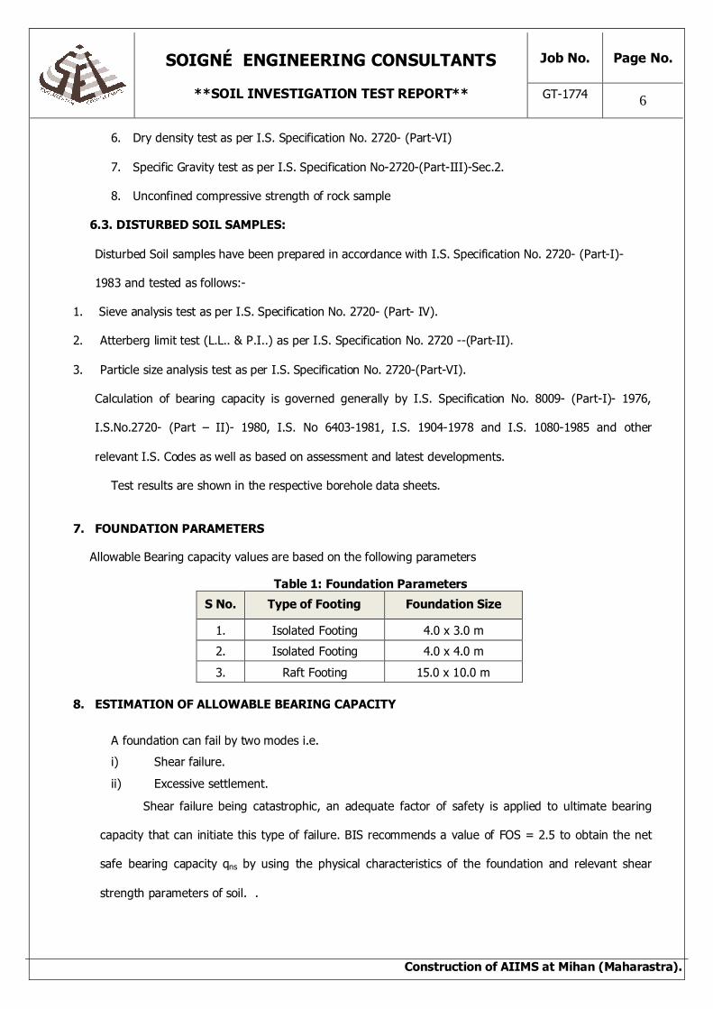
7. FOUNDATION PARAMETERS
Allowable Bearing capacity values are based on the following parameters
Table 1: Foundation Parameters
S No. Type of Footing Foundation Size
1. Isolated Footing 4.0 x 3.0 m
2. Isolated Footing 4.0 x 4.0 m
3. Raft Footing 15.0 x 10.0 m
8. ESTIMATION OF ALLOWABLE BEARING CAPACITY
A foundation can fail by two modes i.e.
i) Shear failure.
ii) Excessive settlement.
Shear failure being catastrophic, an adequate factor of safety is applied to ultimate bearing
capacity that can initiate this type of failure. BIS recommends a value of FOS = 2.5 to obtain the net
safe bearing capacity qns by using the physical characteristics of the foundation and relevant shear
strength parameters of soil. .

SOIGNÉ ENGINEERING CONSULTANTS
**SOIL INVESTIGATION TEST REPORT**
Job No. Page No.
GT-1774
7
Construction of AIIMS at Mihan (Maharastra).
Settlement analysis a net loading intensity qn is obtained by using the physical characteristics of
the foundation and the relevant compressibility characteristics of the Underlying soil. The value so
obtained ensures that the foundation shall not settle more than that which is permissible as per BIS
recommendations. The permissible settlement depends upon the type of superstructure and the nature
of supporting strata.
The lesser of these computed values i.e. qns or qn is adopted as the allowable bearing capacity
for proportioning the foundation of superstructures
9. COMPUTATION OF ALLOWABLE BEARING CAPACITY
Table 2: SPT N-Value and Angle of Shearing Resistance
S.No. Bore Hole No. Depth (m) Angle of Shearing
Resistance, Ф (from fig 9, IS 6403-1981)
1. BHL – 1 to BHL-14
1.5 32.00
2.0 32.00
3.0 36.00
SHEAR FAILURE ANALYSIS
Net Ultimate bearing capacity for general shear failure,
qnu = c Nc Sc Dc + q (Nq-1) Sq Dq + ½ B γ Nγ Sγ Dγ W’ --------(1)
Net Ultimate bearing capacity for local shear failure,
qnu = 2/3 c Nc Sc Dc + q (N’q-1) Sq Dq + ½ B γ N’γ Sγ Dγ W’ --------(2)
Shape factors,
For Strip Footing:
Sc = 1 ; Sq = 1 ; Sy = 1
For Rectangle Footing:
Sc = 1+0.2 B/L ; Sq = 1+0.2 B/L ; Sy = 1-0.4 B/L
For Square Footing:
Sc = 1.3 ; Sq = 1.2 ; Sy = 0.8
For Circular Footing:
Sc = 1.3 ; Sq = 1.2 ; Sy = 0.6
Depth factors,
dc = 1 + 0.2 x D/B Tan(45 + Φ/2) ; dq = dy = 1 + 0.1 x D/B Tan(45 + Φ/2)
(For Cohesive soil, Φ = 0)
Inclination Factors,
ic = 1.0 ; iq = 1.0 ; iγ = 1.0

SOIGNÉ ENGINEERING CONSULTANTS
**SOIL INVESTIGATION TEST REPORT**
Job No. Page No.
GT-1774
8
Construction of AIIMS at Mihan (Maharastra).
SETTLEMENT ANALYSIS
As per BIS recommendation permissible settlement for footing on Rock Mass is 12.0 mm.
Because of the erratic and pronounced variations of the compressibility characteristics of supporting
strata, even slight differential settlement can cause distress to superstructure. As such differential
settlement should be kept as low as possible. Depending upon the ability of the strata to absorb
settlements, maximum permissible settlement is conservatively chosen so that resultant differential
settlements do not cause distress to the superstructure.
Max. Settlement in cohesion less soil is calculated from IS 8009(Part I):1976, from fig. 9
SOIGNÉ ENGINEERING CONSULTANTS
**SOIL INVESTIGATION TEST REPORT**
Job No. Page No.
GT-1774
9
Construction of AIIMS at Mihan (Maharastra).
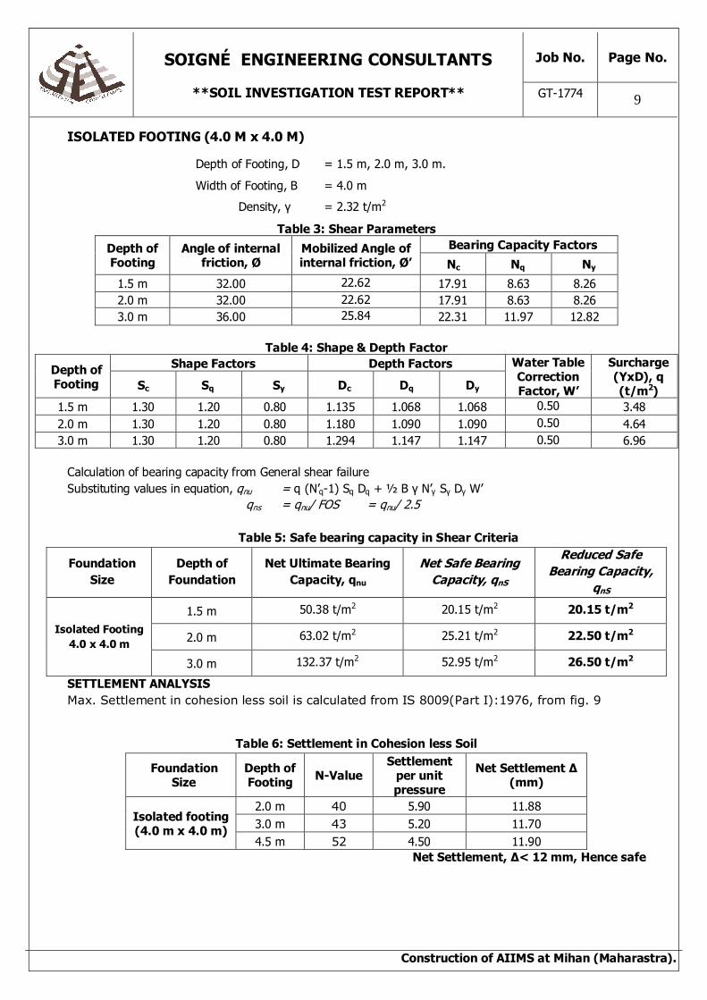
ISOLATED FOOTING (4.0 M x 4.0 M)
Depth of Footing, D = 1.5 m, 2.0 m, 3.0 m.
Width of Footing, B = 4.0 m
Density, γ = 2.32 t/m2
Table 3: Shear Parameters
Depth of Footing
Angle of internal friction, Ø
Mobilized Angle of internal friction, Ø’
Bearing Capacity Factors
Nc Nq Ny
1.5 m 32.00 22.62 17.91 8.63 8.26
2.0 m 32.00 22.62 17.91 8.63 8.26
3.0 m 36.00 25.84 22.31 11.97 12.82
Table 4: Shape & Depth Factor
Depth of Footing
Shape Factors Depth Factors Water Table Correction Factor, W’
Surcharge (YxD), q (t/m2) Sc Sq Sy Dc Dq Dy
1.5 m 1.30 1.20 0.80 1.135 1.068 1.068 0.50 3.48
2.0 m 1.30 1.20 0.80 1.180 1.090 1.090 0.50 4.64
3.0 m 1.30 1.20 0.80 1.294 1.147 1.147 0.50 6.96
Calculation of bearing capacity from General shear failure
Substituting values in equation, qnu = q (N’q-1) Sq Dq + ½ B γ N’γ Sγ Dγ W’
qns = qnu/ FOS = qnu/ 2.5
Table 5: Safe bearing capacity in Shear Criteria
Foundation Size
Depth of Foundation
Net Ultimate Bearing Capacity, qnu
Net Safe Bearing Capacity, qnS
Reduced Safe Bearing Capacity,
qnS
Isolated Footing 4.0 x 4.0 m
1.5 m 50.38 t/m2 20.15 t/m2 20.15 t/m2
2.0 m 63.02 t/m2 25.21 t/m2 22.50 t/m2
3.0 m 132.37 t/m2 52.95 t/m2 26.50 t/m2
SETTLEMENT ANALYSIS Max. Settlement in cohesion less soil is calculated from IS 8009(Part I):1976, from fig. 9
Table 6: Settlement in Cohesion less Soil
Foundation Size
Depth of Footing N-Value
Settlement per unit pressure
Net Settlement Δ
(mm)
Isolated footing (4.0 m x 4.0 m)
2.0 m 40 5.90 11.88
3.0 m 43 5.20 11.70
4.5 m 52 4.50 11.90
Net Settlement, Δ< 12 mm, Hence safe

SOIGNÉ ENGINEERING CONSULTANTS
**SOIL INVESTIGATION TEST REPORT**
Job No. Page No.
GT-1774
10
Construction of AIIMS at Mihan (Maharastra).
ISOLATED FOOTING (4.0 M x 3.0 M)
Depth of Footing, D = 1.5 m, 2.0 m, 3.0 m.
Width of Footing, B = 3.0 m
Density, γ = 2.32 t/m2
Table 7: Shear Parameters
Depth of Footing
Angle of internal friction, Ø
Mobilized Angle of internal friction, Ø’
Bearing Capacity Factors
Nc Nq Ny
1.5 m 32.00 22.62 17.91 8.63 8.26
2.0 m 32.00 22.62 17.91 8.63 8.26
3.0 m 36.00 25.84 22.31 11.97 12.82
Table 8: Shape & Depth Factor
Depth of Footing
Shape Factors Depth Factors Water Table Correction Factor, W’
Surcharge (YxD), q (t/m2) Sc Sq Sy Dc Dq Dy
1.5 m 1.15 1.15 0.70 1.180 1.090 1.090 0.50 3.48
2.0 m 1.15 1.15 0.70 1.240 1.120 1.120 0.50 4.64
3.0 m 1.15 1.15 0.70 1.392 1.196 1.196 0.50 6.96
Calculation of bearing capacity from General shear failure
Substituting values in equation, qnu = q (N’q-1) Sq Dq + ½ B γ N’γ Sγ Dγ W’
qns = qnu/ FOS = qnu/ 2.5
Table 9: Safe bearing capacity in Shear Criteria
Foundation Size
Depth of Foundation
Net Ultimate Bearing Capacity, qnu
Net Safe Bearing Capacity, qnS
Reduced Safe Bearing Capacity,
qnS
Isolated Footing 4.0 x 3.0 m
1.5 m 44.25 t/m2 17.70 t/m2 17.70 t/m2
2.0 m 56.87 t/m2 22.75 t/m2 19.60 t/m2
3.0 m 123.67 t/m2 49.47 t/m2 23.50 t/m2
SETTLEMENT ANALYSIS Max. Settlement in cohesion less soil is calculated from IS 8009(Part I):1976, from fig. 9
Table 10: Settlement in Cohesion less Soil
Foundation Size
Depth of Footing N-Value
Settlement per unit pressure
Net Settlement Δ
(mm)
Isolated footing (4.0 m x 4.0 m)
2.0 m 40 6.50 11.50
3.0 m 43 6.00 11.76
4.5 m 52 5.00 11.75
Net Settlement, Δ< 12 mm, Hence safe

SOIGNÉ ENGINEERING CONSULTANTS
**SOIL INVESTIGATION TEST REPORT**
Job No. Page No.
GT-1774
11
Construction of AIIMS at Mihan (Maharastra).
RAFT FOOTING (15.0 M x 10.0 M)
Depth of Footing, D = 1.5 m, 2.0 m, 3.0 m.
Width of Footing, B = 10.0 m
Density, γ = 2.32 t/m2
Table 11: Shear Parameters
Depth of Footing
Angle of internal friction, Ø
Mobilized Angle of internal friction, Ø’
Bearing Capacity Factors
Nc Nq Ny
1.5 m 32.00 22.62 17.91 8.63 8.26
2.0 m 32.00 22.62 17.91 8.63 8.26
3.0 m 36.00 25.84 22.31 11.97 12.82
Table 12: Shape & Depth Factor
Depth of Footing
Shape Factors Depth Factors Water Table Correction Factor, W’
Surcharge (YxD), q (t/m2) Sc Sq Sy Dc Dq Dy
1.5 m 1.13 1.13 0.73 1.054 1.027 1.027 0.50 3.48
2.0 m 1.13 1.13 0.73 1.072 1.036 1.036 0.50 4.64
3.0 m 1.13 1.13 0.73 1.118 1.059 1.059 0.50 6.96
Calculation of bearing capacity from General shear failure
Substituting values in equation, qnu = q (N’q-1) Sq Dq + ½ B γ N’γ Sγ Dγ W’
qns = qnu/ FOS = qnu/ 2.5
Table 13: Safe bearing capacity in Shear Criteria
Foundation Size
Depth of Foundation
Net Ultimate Bearing Capacity, qnu
Net Safe Bearing Capacity, qnS
Reduced Safe Bearing Capacity,
qnS
Raft Footing 15.0 x 10.0 m
1.5 m 66.99 t/m2 26.80 t/m2 17.00 t/m2
2.0 m 77.97 t/m2 31.19 t/m2 19.00 t/m2
3.0 m 149.35 t/m2 59.74 t/m2 21.50 t/m2
SETTLEMENT ANALYSIS Max. Settlement in cohesion less soil is calculated from IS 8009(Part I):1976, from fig. 9
Table 14: Settlement in Cohesion less Soil
Foundation Size
Depth of Footing N-Value
Settlement per unit pressure
Net Settlement Δ
(mm)
Raft footing (15.0 m x 10.0
m)
2.0 m 40 7.00 11.50
3.0 m 43 6.20 11.78
4.5 m 52 5.50 11.82
Net Settlement, Δ< 12 mm, Hence safe

SOIGNÉ ENGINEERING CONSULTANTS
**SOIL INVESTIGATION TEST REPORT**
Job No. Page No.
GT-1774
12
Construction of AIIMS at Mihan (Maharastra).
10. COMPUTATION OF ALLOWABLE BEARING CAPACITY FROM PLATE LOAD TEST
For proposed foundation the computations have been done for the open foundation at 2.0 m from
existing Ground Level. These analyses and test results have been reported below, Since there is no failure
observed till the maximum applied load . The load intensity obtained from the max load is 55.88 t/m2.
From PLT-1,
Foundation Size 4.0m x 4.0m
Ultimate bearing capacity from load settlement curve (qup) = 55.88 t/m2
Ultimate bearing capacity for Foundation (quf)= 55.8 x 4.0 /0.75 = 297.6 t/m2
Using FOS = 2.5, net allowable bearing capacity, qf = quf /FOS
= 119.04 t/m2.
SETTLEMENT ANALYSIS
From settlement consideration, the settlement of the test plate Sp of width BP, corresponding to
settlement Sf for a foundation width of Bf can be worked out from the following equation,
Sf = Sp [{B x (Bp + 0.3)} / {Bp x (B + 0.3)}] 2
Where Bp and Bf are in cm.
Sf = Maximum Permissible Settlement = 12.0 mm
Bp = Width of plate
Bf = Width of footing
Sp = Maximum Settlement of plate
qs = Bearing Capacity of Foundation from Load Settlement Curve
S.No Location Settlement of Plate (mm)
Allowable Pressure (t/m2)
For 4.0m wide footing For 4.0m wide footing
1. PLT – 1 7.10 mm 64.00

SOIGNÉ ENGINEERING CONSULTANTS
**SOIL INVESTIGATION TEST REPORT**
Job No. Page No.
GT-1774
13
Construction of AIIMS at Mihan (Maharastra).
11. ESTIMATION OF MODULUS OF SUBGRADE REACTION (K-VALUE)
Modulus of Sub grade Reaction (k) is required for foundation & Calculated as per IS
9214-1979 and is estimated from Plate Load Test data.
For PLT-1
By equation,
K = p/0.125 Kgf/cm2 /cm
Where,
‘K’ = Modulus of Sub grade Reaction
‘p’ = load intensity required for unit settlement from load-settlement curve at
figure 1 which is 1.36 Kgf/ cm2 /cm
Therefore, k = 1.36/0.125
= 10.88 Kg/cm2/cm

SOIGNÉ ENGINEERING CONSULTANTS
**SOIL INVESTIGATION TEST REPORT**
Job No. Page No.
GT-1774
14
Construction of AIIMS at Mihan (Maharastra).
Allowable Bearing Capacity based upon Unconfined Compressive Strength
The allowable bearing pressure based upon unconfined compressive strengths of undisturbed drill core
samples for rock strata as per Para-6 of IS: 12070-1987, using relationship as per equation:-
qa = qc Nf
Where
Nf = 0.10 (from IS 12070-1987)
qs = Safe bearing pressure (gross)
qc = Uniaxial compressive strength of supporting rock strata in kg/cm2
Safe bearing pressure for various boreholes from Unconfined compressive strength of underlying
rocky strata has been calculated as follows.
S.No. Bore Hole
Location
Depth of Footing, d
(m)
Uniaxial compressive strength, qc
(kg/cm2)
Gross Safe Bearing Pressure,
qs, (t/m2)
Bulk density
of Soil, ү, kg/cm3
Net Safe Bearing Pressure, qs net,
(kg/cm2)
1 BHL – 1 1.50 121.1 121.1 2.26 117.71
2 BHL – 2 1.50 111.5 111.5 2.37 107.94
3 BHL – 3 0.75 101.2 101.2 2.30 99.47
4 BHL – 4 0.75 105.1 105.1 2.32 103.36
5 BHL – 5 0.75 113.6 113.6 2.29 111.88
6 BHL – 6 0.75 115.2 115.2 2.34 113.44
7 BHL – 7 0.75 123.1 123.1 2.27 121.39
8 BHL – 8 0.75 111.1 111.1 2.32 109.36
9 BHL – 9 0.75 107.6 107.6 2.28 105.89
10 BHL – 10 1.50 119.4 119.4 2.34 115.89
11 BHL – 11 0.75 114.1 114.1 2.30 112.37
12 BHL – 12 0.75 117.1 117.1 2.33 115.35
13 BHL – 13 0.75 121.1 121.1 2.31 119.36
14 BHL – 14 1.50 136.8 136.8 2.34 133.29
14 BHL – 15 1.50 127.2 127.2 2.35 123.67
14 BHL – 16 0.75 114.5 114.5 2.34 112.74
14 BHL – 17 0.75 109.4 109.4 2.36 107.63
14 BHL – 18 1.50 131.1 131.1 2.36 129.33

SOIGNÉ ENGINEERING CONSULTANTS
**SOIL INVESTIGATION TEST REPORT**
Job No. Page No.
GT-1774
15
Construction of AIIMS at Mihan (Maharastra).
12. RECOMMENDATIONS
Recommended bearing capacity for different types of foundation may be assumed as follow:
Table 15: Recommendations
Type of foundation
At 1.5 m depth At 2.0 m depth At 3.0 m depth
(qa)net
(t/m2) (qa)gross
(t/m2) (qa)net
(t/m2) (qa)net
(t/m2) (qa)net
(t/m2) (qa)net
(t/m2)
Isolated Footing 17.70 21.18 19.60 24.24 23.50 30.46
Raft Foundation 17.00 20.48 19.00 23.64 21.50 28.46
Modulus of Sub Grade (K- Value) = 10.88 Kg/cm2/cm
Note:
1. Sub Soil Profile observed was predominantly soft clay stone upto 1 m. Beyond 1.0 m hard quartzite
rock was observed and N-Value>50 was observed upto the explored depth from existing ground
level.
2. The area under investigation falls under seismic zone-II as per India seismic code.
3. Sub soil water was encountered in all boreholes. Depth of water table in various boreholes varied
from 0.90 m to 2.5 m.
4. For any other size and depth of footing bearing capacity of soil can be calculated from the data
provided.
5. Designer must consider effect due to uplift pressure due to rise in ground Water table.
6. Since the above soil in saturated cohessionless, therefore effect due to liquefaction of Soil must be
considered and Seismic capacity of Foundations must be worked out.
7. It is also suggested that the backfilling of the foundation soil should be well compacted in layer at
optimum moisture content to achieve at least 95% of proctor density, followed by suitable plinth
protection & effective drainage system.

SOIGNÉ ENGINEERING CONSULTANTS
**SOIL INVESTIGATION TEST REPORT**
Job No. Page No.
GT-1774
16
Construction of AIIMS at Mihan (Maharastra).
ANNEXURE A
Table 16: Plate Load Test Results (PLT-2)
-Load (Kg) Load Intensity (t/m2)
Maximum Settlement of Plate (0.01mm Least Count)
Dial Gauge – 1 Dial Gauge - 2 Average 0 0.00 0 0 0
3125 5.88 53 56 55
6250 11.44 102 98 100
9375 17.00 164 159 162
12500 22.55 215 201 208
15625 28.11 269 259 264
18750 33.66 312 309 311
21875 39.22 363 373 368
25000 44.77 421 423 422
28125 50.33 488 487 488
31250 55.88 525 535 530
0
1
2
3
4
5
6
0.0 10.0 20.0 30.0 40.0 50.0 60.0
SET
TL
EM
EN
T (m
m)
LOAD INTENSITY (t/m2)LOAD INTENSTIY v/s SETTLEMENT PLOT

SOIGNÉ ENGINEERING CONSULTANTS
**SOIL INVESTIGATION TEST REPORT**
Job No. Page No.
GT-1774
17
Construction of AIIMS at Mihan (Maharastra).
LOCATION MAP

SOIGNÉ ENGINEERING CONSULTANTS
**SOIL INVESTIGATION TEST REPORT**
Job No. Page No.
GT-1774
18
Construction of AIIMS at Mihan (Maharastra).
LIST OF I.S. CODES FIELD INVESTIGATION:
1. IS : 1498 – 1970 : Classification and Identification of soils for general engineering purpose (First Revision).
2. IS : 1892 – 1979 : Code of practice for sub surface investigation for foundations (First Revision).
3. IS : 2131 – 1981 : Method of Standard Penetration Tests for soils.
4. IS : 2132 – 1986 : Code of practice for thin walled tube sampling of soils (Second Revision).
5. IS : 4968 – 1976
(Part – 3)
: Method of sub surface sounding for soils : Static cone penetration test.
LABORATORY TESTS:
1. IS 2720 – 1983
(Part – 1)
: Methods of test for soils : Preparation of dry soil sample for various tests (Second Revision).
2. IS : 2720 – 1980
(Part – 2)
: Method of test for soils : Determination of water content (Second Revision).
3. IS : 2720 – 1980
(Part – 3) (Section – 1)
: Method of test for soils : Determination of Specific Gravity : Fine Grained Soils.
4. IS : 2720 – 1980
(Part – 3) (Section – 2)
: Method of test for soils : Determination of Specific Gravity : Fine, Medium, Coarse Grained Soils (First Edition).
5. IS : 2720 – 1985
(Part – 4)
: Method of test for soils : Grain Size Analysis.
6. IS : 2720 – 1985
(Part – 5)
: Method of test for soils : Determination of liquid & plastic limit (Second Revision).
7. IS : 2720 – 1986
(Part – 15)
: Method of test for soils : Determination of consolidation properties (First Revision).
8. IS : 2809 – 1972 : Method of test for soils : Glossary of terms & symbols relating to soil engineering.

SOIGNÉ ENGINEERING CONSULTANTS
**SOIL INVESTIGATION TEST REPORT**
Job No. Page No.
GT-1774
19
Construction of AIIMS at Mihan (Maharastra).
FOUNDATION CONSTRUCTION:
1. IS : 1080 – 1986 : Code of practice for design and construction of shallow foundations
on soils (other than raft, ring and shell) (Second Revision).
2. IS : 1904 – 1986 : Code of practice for design and construction of foundation in soils : General requirements.
3. IS : 1080 – 1986 : Code of practice for design and construction of shallow foundations on soils (other than raft, ring and shell) (Second Revision).
4. IS 6403 – 1981 : Code of practice for determination of bearing capacity of shallow
foundations.
5. IS 8009 – 1976
(Part – 1)
: Code of practice for calculations of settlements of foundations : shallow foundations subject to symmetrical static vertical loads.

SOIGNÉ ENGINEERING CONSULTANTS
**SOIL INVESTIGATION TEST REPORT**
Job No. Page No.
GT-1774
20
Construction of AIIMS at Mihan (Maharastra).
NOTATIONS USED
N = Observed SPT value
CN = Correction factor
NN = Corrected SPT values
γ = Bulk unit weight
γ’ = Submerged unit weight
γ d = Dry unit weight
γ sat = Saturated unit weight
G = Specific gravity of soil
WL = Liquid limit
WP = Plastic limit
IP = Plasticity index
Q u = Unconfined compressive strength
Cu = Undrained shear strength
C = Effective cohesional parameter
Ø = Effective angle of shearing resistance
Ø m = Mobilized angle of shearing resistance
N Ø = Flow value Tan2 (45 + Ø / 2)
GSF = General shear failure
LSF = Local shear failure
C c = Compression index
B = Width of foundation
L = Length of foundation
D = Depth of foundation

SOIGNÉ ENGINEERING CONSULTANTS
**SOIL INVESTIGATION TEST REPORT**
Job No. Page No.
GT-1774
21
Construction of AIIMS at Mihan (Maharastra).
q = Effective surcharge
N γ, Nq, & Nc = Bearing capacity factors
S γ, Sq, & Sc = Shape factors
d γ, dq, & dc = Depth factors
S.S.W.L. = Sub soil water level
W’ = W.T. correction factor
H = Thickness of clayey layer
σ’ o = Original effective overburden pressure
∆ σ = Vertical stress increment
e o = Original void ratio
w = Water content
Ht = Thickness of sandy layer
Bt = Top width of sandy layer
∆ σt = Stress increment at the top of a sandy layer
Df = Depth factor
Lyf = Lateral yield factor
Rf = Rigidity factor
qnf = Net ultimate bearing capacity
qns = Net safe bearing capacity against shear failure
qn = Net foundation loading intensity for a given settlement
qa = Allowable bearing capacity
So = Settlement due to a net unit foundation loading intensity
Sob = Settlement due to a net unit foundation loading intensity
under submerged conditions (1Kg / cm2)

SOIGNÉ ENGINEERING CONSULTANTS
**SOIL INVESTIGATION TEST REPORT**
Job No. Page No.
GT-1774
22
Construction of AIIMS at Mihan (Maharastra).
WT = Water table
St = Total settlement
Sa = Maximum allowable settlement
GW = Well graded gravels
GP = Poorly graded gravels
GM = Silty gravels
GC = Clayey gravels
SW = Well graded sands
SP = Poorly graded sands
SM = Silty sands
SC = Clayey sands
ML = Silt of low compressibility
CL = Clay of low plasticity
MI = Silt of medium compressibility
CI = Clay of medium plasticity
MH = Silt of high compressibility
CH = Clay of high plasticity
M(NP) = Non plastic silt
ML-CL = Mixture of ML and CL
Location:As per Location map
S.N
O
TY
PE
OF
SA
MP
LE
DE
SC
RIP
TIO
N O
F S
TR
AT
A
OB
SE
RV
ED
DC
PT
V
ALU
E
Depth v/s DCPT N-value Graph
% L
IQU
ID L
IMIT
% P
LAS
TIC
LIM
IT
% P
LAS
TIC
IN
DE
X
Dia
of
Co
re(c
m)
* (
kg/c
m2)
BU
LK D
EN
SIT
Y
(gm
s/cc
)
DR
Y D
EN
SIT
Y (
g/c
c)
Page No.
1 GT - 1774
Bore Hole Job No.SOIGNÉ ENGINEERING CONSULTANTS
PROJECT :-Construction of AIIMS at Mihan (Maharashtra).
Client :- Deputy General Manager (Civil), HSCC (I) Ltd Water table depth - 2.30 m
Po
rosi
ty %
Sp
. G
RA
VIT
Y
DE
PT
H F
RO
M N
.S.L
. (m
)
Sample SUB SOIL PROFILE Atterbergs Limit Density
% M
OIS
TU
RE
CO
NT
EN
T
Vo
id R
atio
S.N
O
TY
PE
OF
SA
MP
LE
DE
SC
RIP
TIO
N O
F S
TR
AT
A
OB
SE
RV
ED
DC
PT
V
ALU
E
% L
IQU
ID L
IMIT
% P
LAS
TIC
LIM
IT
% P
LAS
TIC
IN
DE
X
Dia
of
Co
re(c
m)
qc*
(kg
/cm
BU
LK D
EN
SIT
Y
(gm
s/cc
)
DR
Y D
EN
SIT
Y (
g/c
c)
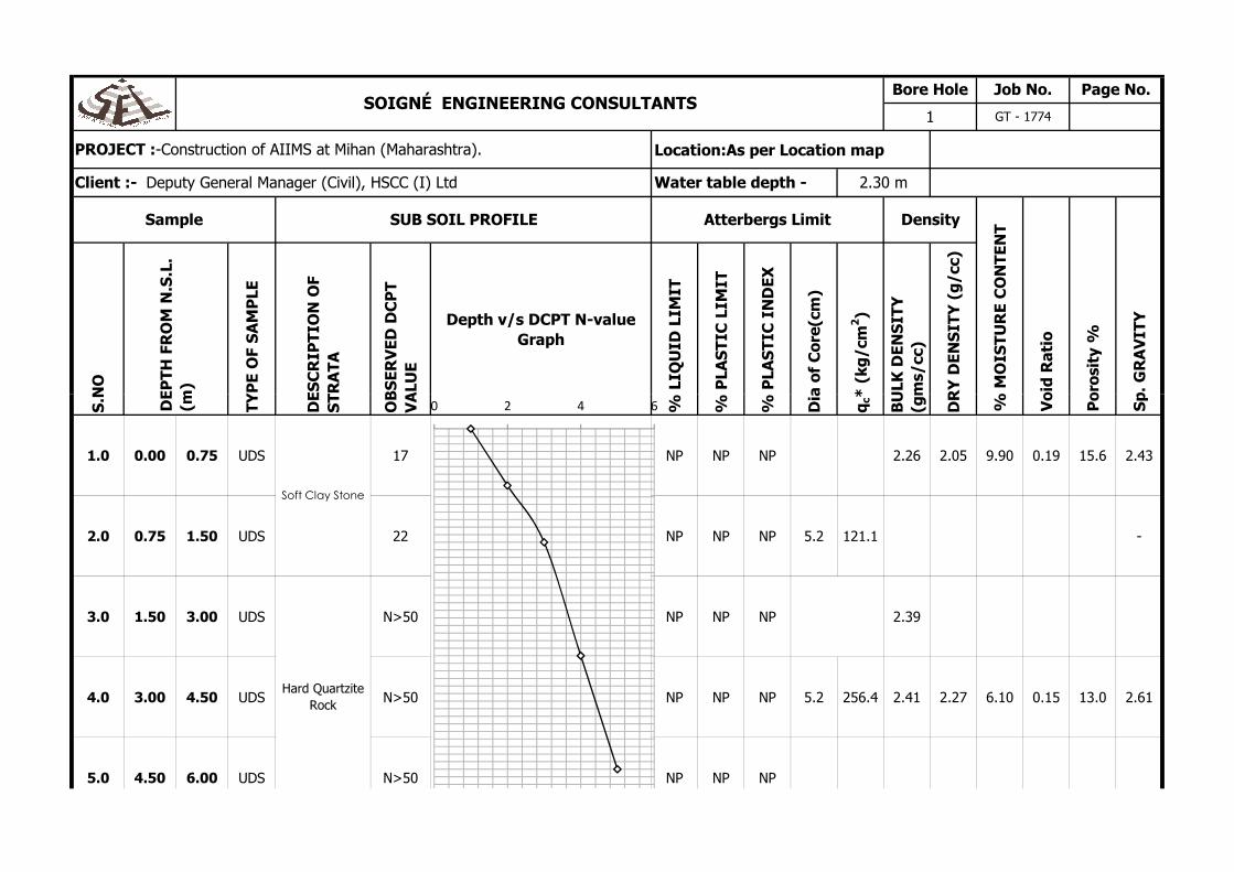
1.0 0.00 0.75 UDS 17 NP NP NP 2.26 2.05 9.90 0.19 15.6 2.43
2.0 0.75 1.50 UDS 22 NP NP NP 5.2 121.1 -
3.0 1.50 3.00 UDS N>50 NP NP NP 2.39
4.0 3.00 4.50 UDS N>50 NP NP NP 5.2 256.4 2.41 2.27 6.10 0.15 13.0 2.61
5.0 4.50 6.00 UDS N>50 NP NP NP
Po
rosi
ty %
Sp
. G
RA
VIT
Y
DE
PT
H F
RO
M N
.S.L
. (m
)
Soft Clay Stone
Hard Quartzite
Rock
% M
OIS
TU
RE
CO
NT
EN
T
Vo
id R
atio
0 2 4 6

Location:As per Location map
S.N
O
TY
PE
OF
SA
MP
LE
DE
SC
RIP
TIO
N O
F S
TR
AT
A
OB
SE
RV
ED
DC
PT
V
ALU
E
Depth v/s DCPT N-value Graph
% L
IQU
ID L
IMIT
% P
LAS
TIC
LIM
IT
% P
LAS
TIC
IN
DE
X
Dia
of
Co
re(c
m)
* (
kg/c
m2)
BU
LK D
EN
SIT
Y
(gm
s/cc
)
DR
Y D
EN
SIT
Y (
g/c
c)
Po
rosi
ty %
Sp
. G
RA
VIT
Y
DE
PT
H F
RO
M N
.S.L
. (m
)
Sample SUB SOIL PROFILE Atterbergs Limit Density
% M
OIS
TU
RE
CO
NT
EN
T
Vo
id R
atio
PROJECT :-Construction of AIIMS at Mihan (Maharashtra).
Client :- Deputy General Manager (Civil), HSCC (I) Ltd Water table depth - 1.40 m
SOIGNÉ ENGINEERING CONSULTANTSBore Hole Job No. Page No.
2 GT - 1774
S.N
O
TY
PE
OF
SA
MP
LE
DE
SC
RIP
TIO
N O
F S
TR
AT
A
OB
SE
RV
ED
DC
PT
V
ALU
E
% L
IQU
ID L
IMIT
% P
LAS
TIC
LIM
IT
% P
LAS
TIC
IN
DE
X
Dia
of
Co
re(c
m)
qc*
(kg
/cm
BU
LK D
EN
SIT
Y
(gm
s/cc
)
DR
Y D
EN
SIT
Y (
g/c
c)
1.0 0.00 0.75 UDS - NP NP NP
2.0 0.75 1.50 UDS 19 NP NP NP 2.37 2.19 4.90 0.17 14.5 2.56
3.0 1.50 3.00 UDS 37 NP NP NP 5.2 111.5
4.0 3.00 4.50 UDS N>50 NP NP NP 2.41 2.26 6.70 0.14 12.4 2.58
5.0 4.50 6.00 UDS N>50 NP NP NP 5.2 269.7
Po
rosi
ty %
Sp
. G
RA
VIT
Y
DE
PT
H F
RO
M N
.S.L
. (m
)
Hard Quartzite
Rock
Soft Clay Stone
% M
OIS
TU
RE
CO
NT
EN
T
Vo
id R
atio
0 2 4 6
Location:As per Location map
S.N
O
TY
PE
OF
SA
MP
LE
DE
SC
RIP
TIO
N O
F S
TR
AT
A
OB
SE
RV
ED
DC
PT
V
ALU
E
Depth v/s DCPT N-value Graph
% L
IQU
ID L
IMIT
% P
LAS
TIC
LIM
IT
% P
LAS
TIC
IN
DE
X
Dia
of
Co
re(c
m)
* (
kg/c
m2)
BU
LK D
EN
SIT
Y
(gm
s/cc
)
DR
Y D
EN
SIT
Y (
g/c
c)
Po
rosi
ty %
Sp
. G
RA
VIT
Y
DE
PT
H F
RO
M N
.S.L
. (m
)
Sample SUB SOIL PROFILE Atterbergs Limit Density
% M
OIS
TU
RE
CO
NT
EN
T
Vo
id R
atio
PROJECT :-Construction of AIIMS at Mihan (Maharashtra).
Client :- Deputy General Manager (Civil), HSCC (I) Ltd Water table depth - 1.10 m
SOIGNÉ ENGINEERING CONSULTANTSBore Hole Job No. Page No.
3 GT - 1774
S.N
O
TY
PE
OF
SA
MP
LE
DE
SC
RIP
TIO
N O
F S
TR
AT
A
OB
SE
RV
ED
DC
PT
V
ALU
E
% L
IQU
ID L
IMIT
% P
LAS
TIC
LIM
IT
% P
LAS
TIC
IN
DE
X
Dia
of
Co
re(c
m)
qc*
(kg
/cm
BU
LK D
EN
SIT
Y
(gm
s/cc
)
DR
Y D
EN
SIT
Y (
g/c
c)
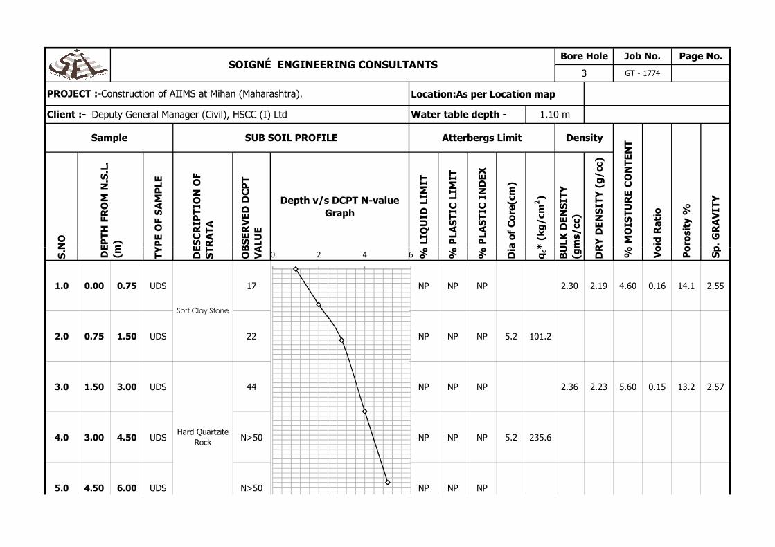
1.0 0.00 0.75 UDS 17 NP NP NP 2.30 2.19 4.60 0.16 14.1 2.55
2.0 0.75 1.50 UDS 22 NP NP NP 5.2 101.2
3.0 1.50 3.00 UDS 44 NP NP NP 2.36 2.23 5.60 0.15 13.2 2.57
4.0 3.00 4.50 UDS N>50 NP NP NP 5.2 235.6
5.0 4.50 6.00 UDS N>50 NP NP NP
Po
rosi
ty %
Sp
. G
RA
VIT
Y
DE
PT
H F
RO
M N
.S.L
. (m
)
Soft Clay Stone
Hard Quartzite
Rock
% M
OIS
TU
RE
CO
NT
EN
T
Vo
id R
atio
0 2 4 6

Location:As per Location map
S.N
O
TY
PE
OF
SA
MP
LE
DE
SC
RIP
TIO
N O
F S
TR
AT
A
OB
SE
RV
ED
DC
PT
V
ALU
E
Depth v/s DCPT N-value Graph
% L
IQU
ID L
IMIT
% P
LAS
TIC
LIM
IT
% P
LAS
TIC
IN
DE
X
Dia
of
Co
re(c
m)
* (
kg/c
m2)
BU
LK D
EN
SIT
Y
(gm
s/cc
)
DR
Y D
EN
SIT
Y (
g/c
c)
Po
rosi
ty %
Sp
. G
RA
VIT
Y
DE
PT
H F
RO
M N
.S.L
. (m
)
Sample SUB SOIL PROFILE Atterbergs Limit Density
% M
OIS
TU
RE
CO
NT
EN
T
Vo
id R
atio
PROJECT :-Construction of AIIMS at Mihan (Maharashtra).
Client :- Deputy General Manager (Civil), HSCC (I) Ltd Water table depth - 1.0 m
SOIGNÉ ENGINEERING CONSULTANTSBore Hole Job No. Page No.
4 GT - 1774
S.N
O
TY
PE
OF
SA
MP
LE
DE
SC
RIP
TIO
N O
F S
TR
AT
A
OB
SE
RV
ED
DC
PT
V
ALU
E
% L
IQU
ID L
IMIT
% P
LAS
TIC
LIM
IT
% P
LAS
TIC
IN
DE
X
Dia
of
Co
re(c
m)
qc*
(kg
/cm
BU
LK D
EN
SIT
Y
(gm
s/cc
)
DR
Y D
EN
SIT
Y (
g/c
c)
1.0 0.00 0.75 UDS 20 NP NP NP 2.32 2.20 5.10 0.15 13.0 2.53
2.0 0.75 1.50 UDS 29 NP NP NP 5.2 105.1
3.0 1.50 3.00 UDS 47 NP NP NP 2.35 2.21 6.00 0.16 13.7 2.56
4.0 3.00 4.50 UDS N>50 NP NP NP
5.0 4.50 6.00 UDS N>50 NP NP NP 5.2 296.4 2.4 2.2 6.6 0.16 13.6 2.58
Po
rosi
ty %
Sp
. G
RA
VIT
Y
DE
PT
H F
RO
M N
.S.L
. (m
)
Soft Clay Stone
Hard Quartzite
Rock
% M
OIS
TU
RE
CO
NT
EN
T
Vo
id R
atio
0 2 4 6

Location:As per Location map
S.N
O
TY
PE
OF
SA
MP
LE
DE
SC
RIP
TIO
N O
F S
TR
AT
A
OB
SE
RV
ED
DC
PT
V
ALU
E
Depth v/s DCPT N-value Graph
% L
IQU
ID L
IMIT
% P
LAS
TIC
LIM
IT
% P
LAS
TIC
IN
DE
X
Dia
of
Co
re(c
m)
* (
kg/c
m2)
BU
LK D
EN
SIT
Y
(gm
s/cc
)
DR
Y D
EN
SIT
Y (
g/c
c)
Po
rosi
ty %
Sp
. G
RA
VIT
Y
DE
PT
H F
RO
M N
.S.L
. (m
)
Sample SUB SOIL PROFILE Atterbergs Limit Density
% M
OIS
TU
RE
CO
NT
EN
T
Vo
id R
atio
PROJECT :-Construction of AIIMS at Mihan (Maharashtra).
Client :- Deputy General Manager (Civil), HSCC (I) Ltd Water table depth - 1.5 m
SOIGNÉ ENGINEERING CONSULTANTSBore Hole Job No. Page No.
5 GT - 1774
S.N
O
TY
PE
OF
SA
MP
LE
DE
SC
RIP
TIO
N O
F S
TR
AT
A
OB
SE
RV
ED
DC
PT
V
ALU
E
% L
IQU
ID L
IMIT
% P
LAS
TIC
LIM
IT
% P
LAS
TIC
IN
DE
X
Dia
of
Co
re(c
m)
qc*
(kg
/cm
BU
LK D
EN
SIT
Y
(gm
s/cc
)
DR
Y D
EN
SIT
Y (
g/c
c)
1.0 0.00 0.75 UDS 24 NP NP NP 2.29 2.19 4.40 0.16 13.8 2.54
2.0 0.75 1.50 UDS 37 NP NP NP 5.2 113.6
3.0 1.50 3.00 UDS N>50 NP NP NP 2.34 2.22 5.00 0.15 13.3 2.56
4.0 3.00 4.50 UDS N>50 NP NP NP 5.2 301.4
5.0 4.50 6.00 UDS N>50 NP NP NP 2.4 2.2 5.5 0.16 13.8 2.60
Po
rosi
ty %
Sp
. G
RA
VIT
Y
DE
PT
H F
RO
M N
.S.L
. (m
)
Soft Clay Stone
Hard Quartzite
Rock
% M
OIS
TU
RE
CO
NT
EN
T
Vo
id R
atio
0 2 4 6

Location:As per Location map
S.N
O
TY
PE
OF
SA
MP
LE
DE
SC
RIP
TIO
N O
F S
TR
AT
A
OB
SE
RV
ED
DC
PT
V
ALU
E
Depth v/s DCPT N-value Graph
% L
IQU
ID L
IMIT
% P
LAS
TIC
LIM
IT
% P
LAS
TIC
IN
DE
X
Dia
of
Co
re(c
m)
* (
kg/c
m2)
BU
LK D
EN
SIT
Y
(gm
s/cc
)
DR
Y D
EN
SIT
Y (
g/c
c)
Po
rosi
ty %
Sp
. G
RA
VIT
Y
DE
PT
H F
RO
M N
.S.L
. (m
)
Sample SUB SOIL PROFILE Atterbergs Limit Density
% M
OIS
TU
RE
CO
NT
EN
T
Vo
id R
atio
PROJECT :-Construction of AIIMS at Mihan (Maharashtra).
Client :- Deputy General Manager (Civil), HSCC (I) Ltd Water table depth - 0.90 m
SOIGNÉ ENGINEERING CONSULTANTSBore Hole Job No. Page No.
6 GT - 1774
S.N
O
TY
PE
OF
SA
MP
LE
DE
SC
RIP
TIO
N O
F S
TR
AT
A
OB
SE
RV
ED
DC
PT
V
ALU
E
% L
IQU
ID L
IMIT
% P
LAS
TIC
LIM
IT
% P
LAS
TIC
IN
DE
X
Dia
of
Co
re(c
m)
qc*
(kg
/cm
BU
LK D
EN
SIT
Y
(gm
s/cc
)
DR
Y D
EN
SIT
Y (
g/c
c)
1.0 0.00 0.75 UDS 23 NP NP NP 2.34 2.21 5.60 0.17 14.3 2.58
2.0 0.75 1.50 UDS 31 NP NP NP 5.2 115.2
3.0 1.50 3.00 UDS N>50 NP NP NP 2.38 2.26 4.90 0.16 13.7 2.62
4.0 3.00 4.50 UDS N>50 NP NP NP 5.2 289.4
5.0 4.50 6.00 UDS N>50 NP NP NP 2.4 2.3 5.9 0.16 13.7 2.63
Po
rosi
ty %
Sp
. G
RA
VIT
Y
DE
PT
H F
RO
M N
.S.L
. (m
)
Soft Clay Stone
Hard Quartzite
Rock
% M
OIS
TU
RE
CO
NT
EN
T
Vo
id R
atio
0 2 4 6

Location:As per Location map
S.N
O
TY
PE
OF
SA
MP
LE
DE
SC
RIP
TIO
N O
F S
TR
AT
A
OB
SE
RV
ED
DC
PT
V
ALU
E
Depth v/s DCPT N-value Graph
% L
IQU
ID L
IMIT
% P
LAS
TIC
LIM
IT
% P
LAS
TIC
IN
DE
X
Dia
of
Co
re(c
m)
* (
kg/c
m2)
BU
LK D
EN
SIT
Y
(gm
s/cc
)
DR
Y D
EN
SIT
Y (
g/c
c)
Po
rosi
ty %
Sp
. G
RA
VIT
Y
DE
PT
H F
RO
M N
.S.L
. (m
)
Sample SUB SOIL PROFILE Atterbergs Limit Density
% M
OIS
TU
RE
CO
NT
EN
T
Vo
id R
atio
PROJECT :-Construction of AIIMS at Mihan (Maharashtra).
Client :- Deputy General Manager (Civil), HSCC (I) Ltd Water table depth - 1.30 m
SOIGNÉ ENGINEERING CONSULTANTSBore Hole Job No. Page No.
7 GT - 1774
S.N
O
TY
PE
OF
SA
MP
LE
DE
SC
RIP
TIO
N O
F S
TR
AT
A
OB
SE
RV
ED
DC
PT
V
ALU
E
% L
IQU
ID L
IMIT
% P
LAS
TIC
LIM
IT
% P
LAS
TIC
IN
DE
X
Dia
of
Co
re(c
m)
qc*
(kg
/cm
BU
LK D
EN
SIT
Y
(gm
s/cc
)
DR
Y D
EN
SIT
Y (
g/c
c)
1.0 0.00 0.75 UDS 24 NP NP NP 2.27 2.18 3.90 0.16 13.8 2.53
2.0 0.75 1.50 UDS 37 NP NP NP 5.2 123.1
3.0 1.50 3.00 UDS N>50 NP NP NP 2.33 2.21 5.00 0.16 13.7 2.56
4.0 3.00 4.50 UDS N>50 NP NP NP 5.2 312.2
5.0 4.50 6.00 UDS N>50 NP NP NP 2.4 2.3 5.5 0.15 12.7 2.59
Po
rosi
ty %
Sp
. G
RA
VIT
Y
DE
PT
H F
RO
M N
.S.L
. (m
)
Soft Clay Stone
Hard Quartzite
Rock
% M
OIS
TU
RE
CO
NT
EN
T
Vo
id R
atio
0 2 4 6

Location:As per Location map
S.N
O
TY
PE
OF
SA
MP
LE
DE
SC
RIP
TIO
N O
F S
TR
AT
A
OB
SE
RV
ED
DC
PT
V
ALU
E
Depth v/s DCPT N-value Graph
% L
IQU
ID L
IMIT
% P
LAS
TIC
LIM
IT
% P
LAS
TIC
IN
DE
X
Dia
of
Co
re(c
m)
* (
kg/c
m2)
BU
LK D
EN
SIT
Y
(gm
s/cc
)
DR
Y D
EN
SIT
Y (
g/c
c)
Po
rosi
ty %
Sp
. G
RA
VIT
Y
DE
PT
H F
RO
M N
.S.L
. (m
)
Sample SUB SOIL PROFILE Atterbergs Limit Density
% M
OIS
TU
RE
CO
NT
EN
T
Vo
id R
atio
PROJECT :-Construction of AIIMS at Mihan (Maharashtra).
Client :- Deputy General Manager (Civil), HSCC (I) Ltd Water table depth - 1.50 m
SOIGNÉ ENGINEERING CONSULTANTSBore Hole Job No. Page No.
8 GT - 1774
S.N
O
TY
PE
OF
SA
MP
LE
DE
SC
RIP
TIO
N O
F S
TR
AT
A
OB
SE
RV
ED
DC
PT
V
ALU
E
% L
IQU
ID L
IMIT
% P
LAS
TIC
LIM
IT
% P
LAS
TIC
IN
DE
X
Dia
of
Co
re(c
m)
qc*
(kg
/cm
BU
LK D
EN
SIT
Y
(gm
s/cc
)
DR
Y D
EN
SIT
Y (
g/c
c)
1.0 0.00 0.75 UDS 24 NP NP NP 2.32 2.22 4.40 0.14 12.6 2.54
2.0 0.75 1.50 UDS 39 NP NP NP 5.2 111.1
3.0 1.50 3.00 UDS 49 NP NP NP 2.37 2.25 5.10 0.14 12.5 2.57
4.0 3.00 4.50 UDS N>50 NP NP NP 5.2 292.1
5.0 4.50 6.00 UDS N>50 NP NP NP 2.41 2.27 5.9 0.14 12.4 2.59
Po
rosi
ty %
Sp
. G
RA
VIT
Y
DE
PT
H F
RO
M N
.S.L
. (m
)
Soft Clay Stone
Hard Quartzite
Rock
% M
OIS
TU
RE
CO
NT
EN
T
Vo
id R
atio
0 2 4 6

Location:As per Location map
S.N
O
TY
PE
OF
SA
MP
LE
DE
SC
RIP
TIO
N O
F S
TR
AT
A
OB
SE
RV
ED
DC
PT
V
ALU
E
Depth v/s DCPT N-value Graph
% L
IQU
ID L
IMIT
% P
LAS
TIC
LIM
IT
% P
LAS
TIC
IN
DE
X
Dia
of
Co
re(c
m)
* (
kg/c
m2)
BU
LK D
EN
SIT
Y
(gm
s/cc
)
DR
Y D
EN
SIT
Y (
g/c
c)
Po
rosi
ty %
Sp
. G
RA
VIT
Y
DE
PT
H F
RO
M N
.S.L
. (m
)
Sample SUB SOIL PROFILE Atterbergs Limit Density
% M
OIS
TU
RE
CO
NT
EN
T
Vo
id R
atio
PROJECT :-Construction of AIIMS at Mihan (Maharashtra).
Client :- Deputy General Manager (Civil), HSCC (I) Ltd Water table depth - 1.40 m
SOIGNÉ ENGINEERING CONSULTANTSBore Hole Job No. Page No.
9 GT - 1774
S.N
O
TY
PE
OF
SA
MP
LE
DE
SC
RIP
TIO
N O
F S
TR
AT
A
OB
SE
RV
ED
DC
PT
V
ALU
E
% L
IQU
ID L
IMIT
% P
LAS
TIC
LIM
IT
% P
LAS
TIC
IN
DE
X
Dia
of
Co
re(c
m)
qc*
(kg
/cm
BU
LK D
EN
SIT
Y
(gm
s/cc
)
DR
Y D
EN
SIT
Y (
g/c
c)
1.0 0.00 0.75 UDS 19 NP NP NP 2.28 2.19 3.70 0.16 13.8 2.54
2.0 0.75 1.50 UDS 27 NP NP NP 5.2 107.6
3.0 1.50 3.00 UDS 39 NP NP NP 2.35 2.24 4.70 0.14 12.5 2.56
4.0 3.00 4.50 UDS N>50 NP NP NP 5.2 284.1
5.0 4.50 6.00 UDS N>50 NP NP NP 2.40 2.27 5.60 0.14 12.4 2.59
Po
rosi
ty %
Sp
. G
RA
VIT
Y
DE
PT
H F
RO
M N
.S.L
. (m
)
Soft Clay Stone
Hard Quartzite
Rock
% M
OIS
TU
RE
CO
NT
EN
T
Vo
id R
atio
0 2 4 6

Location:As per Location map
S.N
O
TY
PE
OF
SA
MP
LE
DE
SC
RIP
TIO
N O
F S
TR
AT
A
OB
SE
RV
ED
DC
PT
V
ALU
E
Depth v/s DCPT N-value Graph
% L
IQU
ID L
IMIT
% P
LAS
TIC
LIM
IT
% P
LAS
TIC
IN
DE
X
Dia
of
Co
re(c
m)
* (
kg/c
m2)
BU
LK D
EN
SIT
Y
(gm
s/cc
)
DR
Y D
EN
SIT
Y (
g/c
c)
Po
rosi
ty %
Sp
. G
RA
VIT
Y
DE
PT
H F
RO
M N
.S.L
. (m
)
Sample SUB SOIL PROFILE Atterbergs Limit Density
% M
OIS
TU
RE
CO
NT
EN
T
Vo
id R
atio
PROJECT :-Construction of AIIMS at Mihan (Maharashtra).
Client :- Deputy General Manager (Civil), HSCC (I) Ltd Water table depth - 2.50 m
SOIGNÉ ENGINEERING CONSULTANTSBore Hole Job No. Page No.
10 GT - 1774
S.N
O
TY
PE
OF
SA
MP
LE
DE
SC
RIP
TIO
N O
F S
TR
AT
A
OB
SE
RV
ED
DC
PT
V
ALU
E
% L
IQU
ID L
IMIT
% P
LAS
TIC
LIM
IT
% P
LAS
TIC
IN
DE
X
Dia
of
Co
re(c
m)
qc*
(kg
/cm
BU
LK D
EN
SIT
Y
(gm
s/cc
)
DR
Y D
EN
SIT
Y (
g/c
c)
1.0 0.00 0.75 UDS 25 NP NP NP
2.0 0.75 1.50 UDS 29 NP NP NP 2.38 2.24 5.90 0.15 13.2 2.58
3.0 1.50 3.00 UDS N>50 NP NP NP 5.2 119.4
4.0 3.00 4.50 UDS N>50 NP NP NP 2.41 2.26 6.40 0.15 13.1 2.60
5.0 4.50 6.00 UDS N>50 NP NP NP 5.2 286.9
Po
rosi
ty %
Sp
. G
RA
VIT
Y
DE
PT
H F
RO
M N
.S.L
. (m
)
Soft Clay Stone
Hard Quartzite
Rock
% M
OIS
TU
RE
CO
NT
EN
T
Vo
id R
atio
0 2 4 6

Location:As per Location map
S.N
O
TY
PE
OF
SA
MP
LE
DE
SC
RIP
TIO
N O
F S
TR
AT
A
OB
SE
RV
ED
DC
PT
V
ALU
E
Depth v/s DCPT N-value Graph
% L
IQU
ID L
IMIT
% P
LAS
TIC
LIM
IT
% P
LAS
TIC
IN
DE
X
Dia
of
Co
re(c
m)
* (
kg/c
m2)
BU
LK D
EN
SIT
Y
(gm
s/cc
)
DR
Y D
EN
SIT
Y (
g/c
c)
Po
rosi
ty %
Sp
. G
RA
VIT
Y
DE
PT
H F
RO
M N
.S.L
. (m
)
Sample SUB SOIL PROFILE Atterbergs Limit Density
% M
OIS
TU
RE
CO
NT
EN
T
Vo
id R
atio
PROJECT :-Construction of AIIMS at Mihan (Maharashtra).
Client :- Deputy General Manager (Civil), HSCC (I) Ltd Water table depth - 1.40 m
SOIGNÉ ENGINEERING CONSULTANTSBore Hole Job No. Page No.
11 GT - 1774
S.N
O
TY
PE
OF
SA
MP
LE
DE
SC
RIP
TIO
N O
F S
TR
AT
A
OB
SE
RV
ED
DC
PT
V
ALU
E
% L
IQU
ID L
IMIT
% P
LAS
TIC
LIM
IT
% P
LAS
TIC
IN
DE
X
Dia
of
Co
re(c
m)
qc*
(kg
/cm
BU
LK D
EN
SIT
Y
(gm
s/cc
)
DR
Y D
EN
SIT
Y (
g/c
c)
1.0 0.00 0.75 UDS 23 NP NP NP 2.30 2.20 4.40 0.15 13.0 2.53
2.0 0.75 1.50 UDS 36 NP NP NP 5.2 114.1
3.0 1.50 3.00 UDS 47 NP NP NP 2.34 2.21 5.70 0.16 13.7 2.56
4.0 3.00 4.50 UDS N>50 NP NP NP 5.2 296.8
5.0 4.50 6.00 UDS N>50 NP NP NP 2.39 2.24 6.60 0.15 13.2 2.58
Po
rosi
ty %
Sp
. G
RA
VIT
Y
DE
PT
H F
RO
M N
.S.L
. (m
)
Soft Clay Stone
Hard Quartzite
Rock
% M
OIS
TU
RE
CO
NT
EN
T
Vo
id R
atio
0 2 4 6

Location:As per Location map
S.N
O
TY
PE
OF
SA
MP
LE
DE
SC
RIP
TIO
N O
F S
TR
AT
A
OB
SE
RV
ED
DC
PT
V
ALU
E
Depth v/s DCPT N-value Graph
% L
IQU
ID L
IMIT
% P
LAS
TIC
LIM
IT
% P
LAS
TIC
IN
DE
X
Dia
of
Co
re(c
m)
* (
kg/c
m2)
BU
LK D
EN
SIT
Y
(gm
s/cc
)
DR
Y D
EN
SIT
Y (
g/c
c)
Po
rosi
ty %
Sp
. G
RA
VIT
Y
DE
PT
H F
RO
M N
.S.L
. (m
)
Sample SUB SOIL PROFILE Atterbergs Limit Density
% M
OIS
TU
RE
CO
NT
EN
T
Vo
id R
atio
PROJECT :-Construction of AIIMS at Mihan (Maharashtra).
Client :- Deputy General Manager (Civil), HSCC (I) Ltd Water table depth - 1.140 m
SOIGNÉ ENGINEERING CONSULTANTSBore Hole Job No. Page No.
12 GT - 1774
S.N
O
TY
PE
OF
SA
MP
LE
DE
SC
RIP
TIO
N O
F S
TR
AT
A
OB
SE
RV
ED
DC
PT
V
ALU
E
% L
IQU
ID L
IMIT
% P
LAS
TIC
LIM
IT
% P
LAS
TIC
IN
DE
X
Dia
of
Co
re(c
m)
qc*
(kg
/cm
BU
LK D
EN
SIT
Y
(gm
s/cc
)
DR
Y D
EN
SIT
Y (
g/c
c)
1.0 0.00 0.75 UDS 27 NP NP NP 2.33 2.22 4.90 0.15 12.9 2.55
2.0 0.75 1.50 UDS 35 NP NP NP 5.2 117.1
3.0 1.50 3.00 UDS 44 NP NP NP 2.37 2.24 5.70 0.15 12.8 2.57
4.0 3.00 4.50 UDS N>50 NP NP NP 5.2 279.2
5.0 4.50 6.00 UDS N>50 NP NP NP 2.41 2.26 6.50 0.15 13.1 2.60
Po
rosi
ty %
Sp
. G
RA
VIT
Y
DE
PT
H F
RO
M N
.S.L
. (m
)
Soft Clay Stone
Hard Quartzite
Rock
% M
OIS
TU
RE
CO
NT
EN
T
Vo
id R
atio
0 2 4 6

Location:As per Location map
S.N
O
TY
PE
OF
SA
MP
LE
DE
SC
RIP
TIO
N O
F S
TR
AT
A
OB
SE
RV
ED
DC
PT
V
ALU
E
Depth v/s DCPT N-value Graph
% L
IQU
ID L
IMIT
% P
LAS
TIC
LIM
IT
% P
LAS
TIC
IN
DE
X
Dia
of
Co
re(c
m)
* (
kg/c
m2)
BU
LK D
EN
SIT
Y
(gm
s/cc
)
DR
Y D
EN
SIT
Y (
g/c
c)
Po
rosi
ty %
Sp
. G
RA
VIT
Y
DE
PT
H F
RO
M N
.S.L
. (m
)
Sample SUB SOIL PROFILE Atterbergs Limit Density
% M
OIS
TU
RE
CO
NT
EN
T
Vo
id R
atio
PROJECT :-Construction of AIIMS at Mihan (Maharashtra).
Client :- Deputy General Manager (Civil), HSCC (I) Ltd Water table depth - 1.50 m
SOIGNÉ ENGINEERING CONSULTANTSBore Hole Job No. Page No.
13 GT - 1774
S.N
O
TY
PE
OF
SA
MP
LE
DE
SC
RIP
TIO
N O
F S
TR
AT
A
OB
SE
RV
ED
DC
PT
V
ALU
E
% L
IQU
ID L
IMIT
% P
LAS
TIC
LIM
IT
% P
LAS
TIC
IN
DE
X
Dia
of
Co
re(c
m)
qc*
(kg
/cm
BU
LK D
EN
SIT
Y
(gm
s/cc
)
DR
Y D
EN
SIT
Y (
g/c
c)
1.0 0.00 0.75 UDS 27 NP NP NP 2.31 2.19 5.20 0.16 13.4 2.53
2.0 0.75 1.50 UDS 45 NP NP NP 5.2 121.1
3.0 1.50 3.00 UDS N>50 NP NP NP 2.35 2.22 5.70 0.14 12.6 2.54
4.0 3.00 4.50 UDS N>50 NP NP NP 5.2 304.1
5.0 4.50 6.00 UDS N>50 NP NP NP 2.38 2.23 6.30 0.16 13.6 2.58
Po
rosi
ty %
Sp
. G
RA
VIT
Y
DE
PT
H F
RO
M N
.S.L
. (m
)
Soft Clay Stone
Hard Quartzite
Rock
% M
OIS
TU
RE
CO
NT
EN
T
Vo
id R
atio
0 2 4 6

Location:As per Location map
S.N
O
TY
PE
OF
SA
MP
LE
DE
SC
RIP
TIO
N O
F S
TR
AT
A
OB
SE
RV
ED
DC
PT
V
ALU
E
Depth v/s DCPT N-value Graph
% L
IQU
ID L
IMIT
% P
LAS
TIC
LIM
IT
% P
LAS
TIC
IN
DE
X
Dia
of
Co
re(c
m)
* (
kg/c
m2)
BU
LK D
EN
SIT
Y
(gm
s/cc
)
DR
Y D
EN
SIT
Y (
g/c
c)
Po
rosi
ty %
Sp
. G
RA
VIT
Y
DE
PT
H F
RO
M N
.S.L
. (m
)
Sample SUB SOIL PROFILE Atterbergs Limit Density
% M
OIS
TU
RE
CO
NT
EN
T
Vo
id R
atio
PROJECT :-Construction of AIIMS at Mihan (Maharashtra).
Client :- Deputy General Manager (Civil), HSCC (I) Ltd Water table depth - 1.60 m
SOIGNÉ ENGINEERING CONSULTANTSBore Hole Job No. Page No.
14 GT - 1774
S.N
O
TY
PE
OF
SA
MP
LE
DE
SC
RIP
TIO
N O
F S
TR
AT
A
OB
SE
RV
ED
DC
PT
V
ALU
E
% L
IQU
ID L
IMIT
% P
LAS
TIC
LIM
IT
% P
LAS
TIC
IN
DE
X
Dia
of
Co
re(c
m)
qc*
(kg
/cm
BU
LK D
EN
SIT
Y
(gm
s/cc
)
DR
Y D
EN
SIT
Y (
g/c
c)
1.0 0.00 0.75 UDS 25 NP NP NP
2.0 0.75 1.50 UDS 29 NP NP NP 2.37 2.25 5.20 0.15 12.8 2.58
3.0 1.50 3.00 UDS N>50 NP NP NP 5.2 136.4
4.0 3.00 4.50 UDS N>50 NP NP NP 2.40 2.26 5.90 0.15 13.1 2.60
5.0 4.50 6.00 UDS N>50 NP NP NP 5.2 315.4
Po
rosi
ty %
Sp
. G
RA
VIT
Y
DE
PT
H F
RO
M N
.S.L
. (m
)
Soft Clay Stone
Hard Quartzite
Rock
% M
OIS
TU
RE
CO
NT
EN
T
Vo
id R
atio
0 2 4 6

Location:As per Location map
S.N
O
TY
PE
OF
SA
MP
LE
DE
SC
RIP
TIO
N O
F S
TR
AT
A
OB
SE
RV
ED
DC
PT
V
ALU
E
Depth v/s DCPT N-value Graph
% L
IQU
ID L
IMIT
% P
LAS
TIC
LIM
IT
% P
LAS
TIC
IN
DE
X
Dia
of
Co
re(c
m)
* (
kg/c
m2)
BU
LK D
EN
SIT
Y
(gm
s/cc
)
DR
Y D
EN
SIT
Y (
g/c
c)
Po
rosi
ty %
Sp
. G
RA
VIT
Y
DE
PT
H F
RO
M N
.S.L
. (m
)
Atterbergs LimitSample SUB SOIL PROFILE Density
% M
OIS
TU
RE
CO
NT
EN
T
Vo
id R
atio
PROJECT :-Construction of AIIMS at Mihan (Maharashtra).
Client :- Deputy General Manager (Civil), HSCC (I) Ltd Water table depth - 1.70 m
SOIGNÉ ENGINEERING CONSULTANTSBore Hole Job No. Page No.
15 GT - 1774
S.N
O
TY
PE
OF
SA
MP
LE
DE
SC
RIP
TIO
N O
F S
TR
AT
A
OB
SE
RV
ED
DC
PT
V
ALU
E
% L
IQU
ID L
IMIT
% P
LAS
TIC
LIM
IT
% P
LAS
TIC
IN
DE
X
Dia
of
Co
re(c
m)
qc*
(kg
/cm
BU
LK D
EN
SIT
Y
(gm
s/cc
)
DR
Y D
EN
SIT
Y (
g/c
c)
1.0 0.00 0.75 UDS 29 NP NP NP
2.0 0.75 1.50 UDS 36 NP NP NP 2.35 2.22 4.50 0.13 11.6 2.51
3.0 1.50 3.00 UDS 47 NP NP NP 5.2 127.2
4.0 3.00 4.50 UDS N>50 NP NP NP 2.41 2.29 5.70 0.12 10.5 2.56
5.0 4.50 6.00 UDS N>50 NP NP NP 5.2 295.1
Po
rosi
ty %
Sp
. G
RA
VIT
Y
DE
PT
H F
RO
M N
.S.L
. (m
)
Soft Clay Stone
Hard Quartzite
Rock
% M
OIS
TU
RE
CO
NT
EN
T
Vo
id R
atio
0 2 4 6

Location:As per Location map
S.N
O
TY
PE
OF
SA
MP
LE
DE
SC
RIP
TIO
N O
F S
TR
AT
A
OB
SE
RV
ED
DC
PT
V
ALU
E
Depth v/s DCPT N-value Graph
% L
IQU
ID L
IMIT
% P
LAS
TIC
LIM
IT
% P
LAS
TIC
IN
DE
X
Dia
of
Co
re(c
m)
* (
kg/c
m2)
BU
LK D
EN
SIT
Y
(gm
s/cc
)
DR
Y D
EN
SIT
Y (
g/c
c)
Po
rosi
ty %
Sp
. G
RA
VIT
Y
DE
PT
H F
RO
M N
.S.L
. (m
)
Sample SUB SOIL PROFILE Atterbergs Limit Density
% M
OIS
TU
RE
CO
NT
EN
T
Vo
id R
atio
PROJECT :-Construction of AIIMS at Mihan (Maharashtra).
Client :- Deputy General Manager (Civil), HSCC (I) Ltd Water table depth - 1.55 m
SOIGNÉ ENGINEERING CONSULTANTSBore Hole Job No. Page No.
16 GT - 1774
S.N
O
TY
PE
OF
SA
MP
LE
DE
SC
RIP
TIO
N O
F S
TR
AT
A
OB
SE
RV
ED
DC
PT
V
ALU
E
% L
IQU
ID L
IMIT
% P
LAS
TIC
LIM
IT
% P
LAS
TIC
IN
DE
X
Dia
of
Co
re(c
m)
qc*
(kg
/cm
BU
LK D
EN
SIT
Y
(gm
s/cc
)
DR
Y D
EN
SIT
Y (
g/c
c)
1.0 0.00 0.75 UDS 25 NP NP NP 2.34 2.21 4.10 0.15 13.0 2.54
2.0 0.75 1.50 UDS 21 NP NP NP 5.2 114.5
3.0 1.50 3.00 UDS 47 NP NP NP 2.36 2.26 5.20 0.15 12.7 2.59
4.0 3.00 4.50 UDS N>50 NP NP NP 5.2 286.1
5.0 4.50 6.00 UDS N>50 NP NP NP 2.39 2.29 5.60 0.14 12.3 2.61
Po
rosi
ty %
Sp
. G
RA
VIT
Y
DE
PT
H F
RO
M N
.S.L
. (m
)
Soft Clay Stone
Hard Quartzite
Rock
% M
OIS
TU
RE
CO
NT
EN
T
Vo
id R
atio
0 2 4 6
Location:As per Location map
S.N
O
TY
PE
OF
SA
MP
LE
DE
SC
RIP
TIO
N O
F S
TR
AT
A
OB
SE
RV
ED
DC
PT
V
ALU
E
Depth v/s DCPT N-value Graph
% L
IQU
ID L
IMIT
% P
LAS
TIC
LIM
IT
% P
LAS
TIC
IN
DE
X
Dia
of
Co
re(c
m)
* (
kg/c
m2)
BU
LK D
EN
SIT
Y
(gm
s/cc
)
DR
Y D
EN
SIT
Y (
g/c
c)
Po
rosi
ty %
Sp
. G
RA
VIT
Y
DE
PT
H F
RO
M N
.S.L
. (m
)
Sample SUB SOIL PROFILE Atterbergs Limit Density
% M
OIS
TU
RE
CO
NT
EN
T
Vo
id R
atio
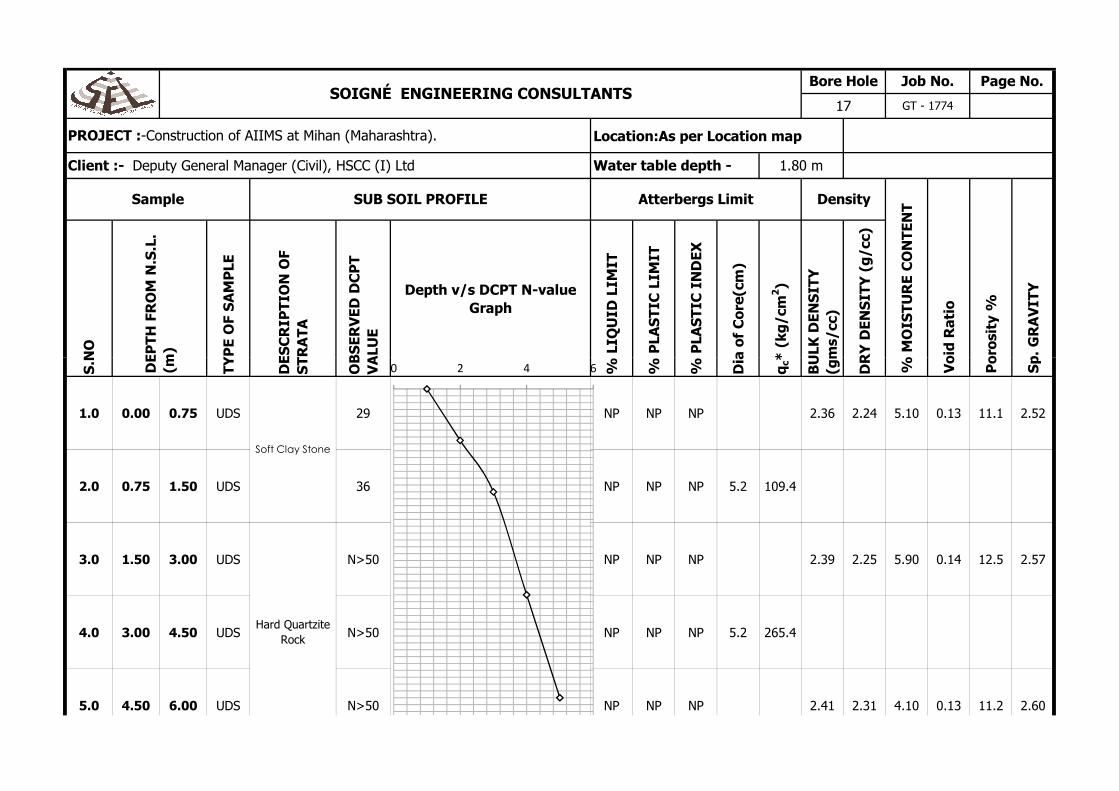
PROJECT :-Construction of AIIMS at Mihan (Maharashtra).
Client :- Deputy General Manager (Civil), HSCC (I) Ltd Water table depth - 1.80 m
SOIGNÉ ENGINEERING CONSULTANTSBore Hole Job No. Page No.
17 GT - 1774
S.N
O
TY
PE
OF
SA
MP
LE
DE
SC
RIP
TIO
N O
F S
TR
AT
A
OB
SE
RV
ED
DC
PT
V
ALU
E
% L
IQU
ID L
IMIT
% P
LAS
TIC
LIM
IT
% P
LAS
TIC
IN
DE
X
Dia
of
Co
re(c
m)
qc*
(kg
/cm
BU
LK D
EN
SIT
Y
(gm
s/cc
)
DR
Y D
EN
SIT
Y (
g/c
c)
1.0 0.00 0.75 UDS 29 NP NP NP 2.36 2.24 5.10 0.13 11.1 2.52
2.0 0.75 1.50 UDS 36 NP NP NP 5.2 109.4
3.0 1.50 3.00 UDS N>50 NP NP NP 2.39 2.25 5.90 0.14 12.5 2.57
4.0 3.00 4.50 UDS N>50 NP NP NP 5.2 265.4
5.0 4.50 6.00 UDS N>50 NP NP NP 2.41 2.31 4.10 0.13 11.2 2.60
Po
rosi
ty %
Sp
. G
RA
VIT
Y
DE
PT
H F
RO
M N
.S.L
. (m
)
Soft Clay Stone
Hard Quartzite
Rock
% M
OIS
TU
RE
CO
NT
EN
T
Vo
id R
atio
0 2 4 6
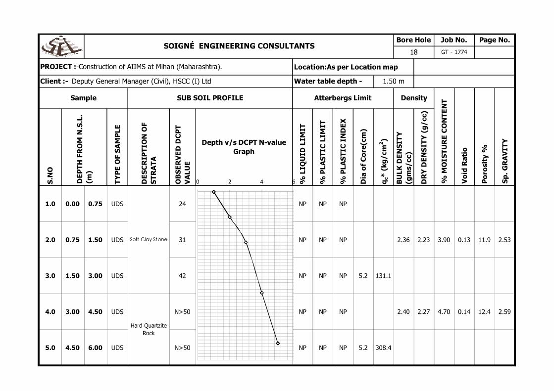
Location:As per Location map
S.N
O
TY
PE
OF
SA
MP
LE
DE
SC
RIP
TIO
N O
F S
TR
AT
A
OB
SE
RV
ED
DC
PT
V
ALU
E
Depth v/s DCPT N-value Graph
% L
IQU
ID L
IMIT
% P
LAS
TIC
LIM
IT
% P
LAS
TIC
IN
DE
X
Dia
of
Co
re(c
m)
qc*
(kg
/cm
2)
BU
LK D
EN
SIT
Y
(gm
s/cc
)
DR
Y D
EN
SIT
Y (
g/c
c)
1.0 0.00 0.75 UDS 24 NP NP NP
2.0 0.75 1.50 UDS 31 NP NP NP 2.36 2.23 3.90 0.13 11.9 2.53
3.0 1.50 3.00 UDS 42 NP NP NP 5.2 131.1
4.0 3.00 4.50 UDS N>50 NP NP NP 2.40 2.27 4.70 0.14 12.4 2.59
5.0 4.50 6.00 UDS N>50 NP NP NP 5.2 308.4
Po
rosi
ty %
Sp
. GR
AV
ITY
DE
PT
H F
RO
M N
.S.L
. (m
)
Soft Clay Stone
Hard Quartzite
Rock
Sample SUB SOIL PROFILE Atterbergs Limit Density
% M
OIS
TU
RE
CO
NT
EN
T
Vo
id R
atio
PROJECT :-Construction of AIIMS at Mihan (Maharashtra).
Client :- Deputy General Manager (Civil), HSCC (I) Ltd Water table depth - 1.50 m
SOIGNÉ ENGINEERING CONSULTANTSBore Hole Job No. Page No.
18 GT - 1774
0 2 4 6

Job No Page No.
GT-1774
DCPT NO. 1
Starting Depth E.G.L.
Termination Depth 4.40 mO
BS
ER
VE
D S
PT
N-
VA
LUE
CO
RR
EC
TE
D S
PT
N-
VA
LUE
1 0.00 5.0 3.3
2 0.30 7.0 4.7
3 0.60 10.0 6.7
SOIGNÉ ENGINEERING CONSULTANTS
PROJECT :- Construction of AIIMS at Mihan (Maharashtra)
Client :- Deputy General Manager (Civil), HSCC (I) Ltd
Location : As per location map
Rem
arks
DCPT v/s SPT N-value Graph
S.N
o.
Dep
th f
rom
EG
L (m
)
Penetration Value DCPT 'N' PROFILE
OBSERVED SPT N-VALUE
Corrected N-Value3 0.60 10.0 6.7
4 0.90 13.0 8.7
5 1.20 14.0 9.3
6 1.50 19.0 12.7
7 1.80 27.0 18.0
8 2.10 41.0 27.3
9 2.40 55.0 36.7
10 2.70 66.0 44.0
11 3.00 85.0 56.7
12 3.30 94.0 62.7
13 3.60 105.0 70.0
14 3.90 115.0 76.7
15 4.20 126.0 84.0
16 4.40 R R
Corrected N-Value

Job No Page No.
GT-1774
DCPT NO. 2
Starting Depth E.G.L.
Termination Depth 4.50 mO
BS
ER
VE
D S
PT
N-
VA
LUE
CO
RR
EC
TE
D S
PT
N-
VA
LUE
1 0.00 10.0 6.7
2 0.30 13.0 8.7
3 0.60 16.0 10.7
S.N
o.
Dep
th f
rom
EG
L (m
)
Penetration Value DCPT 'N' PROFILE
Rem
arks
DCPT v/s SPT N-value Graph
SOIGNÉ ENGINEERING CONSULTANTS
PROJECT :- Construction of AIIMS at Mihan (Maharashtra)
Client :- Deputy General Manager (Civil), HSCC (I) Ltd
Location : As per location map
observed Corrected N-Value3 0.60 16.0 10.7
4 0.90 26.0 17.3
5 1.20 39.0 26.0
6 1.50 53.0 35.3
7 1.80 56.0 37.3
8 2.10 62.0 41.3
9 2.40 65.0 43.3
10 2.70 71.0 47.3
11 3.00 75.0 50.0
12 3.30 85.0 56.7
13 3.60 90.0 60.0
14 3.90 115.0 76.7
15 4.20 125.0 83.3
16 4.50 R R

Job No Page No.
GT-1774
DCPT NO. 3
Starting Depth E.G.L.
Termination Depth 4.30 mO
BS
ER
VE
D S
PT
N-
VA
LUE
CO
RR
EC
TE
D S
PT
N-
VA
LUE
1 0.00 17.0 11.3
2 0.30 18.0 12.0
3 0.60 23.0 15.3
S.N
o.
Dep
th f
rom
EG
L (m
)
Penetration Value DCPT 'N' PROFILE
Rem
arks
DCPT v/s SPT N-value Graph
SOIGNÉ ENGINEERING CONSULTANTS
PROJECT :- Construction of AIIMS at Mihan (Maharashtra)
Client :- Deputy General Manager (Civil), HSCC (I) Ltd
Location : As per location map
obsedrved Corrected N-Value3 0.60 23.0 15.3
4 0.90 31.0 20.7
5 1.20 46.0 30.7
6 1.50 48.0 32.0
7 1.80 51.0 34.0
8 2.10 55.0 36.7
9 2.40 60.0 40.0
10 2.70 62.0 41.3
11 3.00 74.0 49.3
12 3.30 75.0 50.0
13 3.60 86.0 57.3
14 3.90 106.0 70.7
15 4.20 119.0 79.3
16 4.30 R R

Job No Page No.
GT-1774
DCPT NO. 4
Starting Depth E.G.L.
Termination Depth 3.90 mO
BS
ER
VE
D S
PT
N-
VA
LUE
CO
RR
EC
TE
D S
PT
N-
VA
LUE
1 0.00 12.0 8.0
2 0.30 19.0 12.7
S.N
o.
Dep
th f
rom
EG
L (m
)
Penetration Value DCPT 'N' PROFILE
Rem
arks
DCPT v/s SPT N-value Graph
SOIGNÉ ENGINEERING CONSULTANTS
PROJECT :- Construction of AIIMS at Mihan (Maharashtra)
Client :- Deputy General Manager (Civil), HSCC (I) Ltd
Location : As per location map
observed Corrected N-Value
3 0.60 25.0 16.7
4 0.90 30.0 20.0
5 1.20 42.0 28.0
6 1.50 45.0 30.0
7 1.80 56.0 37.3
8 2.10 61.0 40.7
9 2.40 75.0 50.0
10 2.70 83.0 55.3
11 3.00 108.0 72.0
12 3.30 113.0 75.3
13 3.60 128.0 85.3
observed Corrected N-Value
14 3.90 R R
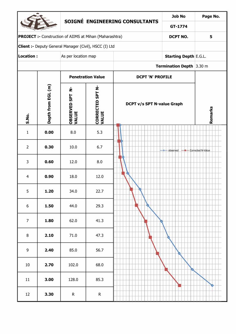
Job No Page No.
GT-1774
DCPT NO. 5
Starting Depth E.G.L.
Termination Depth 3.30 mO
BS
ER
VE
D S
PT
N-
VA
LUE
CO
RR
EC
TE
D S
PT
N-
VA
LUE
1 0.00 8.0 5.3
2 0.30 10.0 6.7
Rem
arks
DCPT v/s SPT N-value Graph
S.N
o.
Dep
th f
rom
EG
L (m
)
Penetration Value DCPT 'N' PROFILE
SOIGNÉ ENGINEERING CONSULTANTS
PROJECT :- Construction of AIIMS at Mihan (Maharashtra)
Client :- Deputy General Manager (Civil), HSCC (I) Ltd
Location : As per location map
observed Corrected N-Value
3 0.60 12.0 8.0
4 0.90 18.0 12.0
5 1.20 34.0 22.7
6 1.50 44.0 29.3
7 1.80 62.0 41.3
8 2.10 71.0 47.3
9 2.40 85.0 56.7
10 2.70 102.0 68.0
11 3.00 128.0 85.3
12 3.30 R R
observed Corrected N-Value

Job No Page No.
GT-1774
DCPT NO. 7
Starting Depth E.G.L.
Termination Depth 3.60 mO
BS
ER
VE
D S
PT
N-
VA
LUE
CO
RR
EC
TE
D S
PT
N-
VA
LUE
1 0.00 9.0 6.0
2 0.30 16.0 10.7
S.N
o.
Dep
th f
rom
EG
L (m
)
Penetration Value DCPT 'N' PROFILE
Rem
arks
DCPT v/s SPT N-value Graph
SOIGNÉ ENGINEERING CONSULTANTS
PROJECT :- Construction of AIIMS at Mihan (Maharashtra)
Client :- Deputy General Manager (Civil), HSCC (I) Ltd
Location : As per location map
observed Corrected N-Value
3 0.60 21.0 14.0
4 0.90 31.0 20.7
5 1.20 40.0 26.7
6 1.50 55.0 36.7
7 1.80 68.0 45.3
8 2.10 78.0 52.0
9 2.40 98.0 65.3
10 2.70 108.0 72.0
11 3.00 125.0 83.3
12 3.30 139.0 92.7
13 3.60 R R
observed Corrected N-Value

Job No Page No.
GT-1774
DCPT NO. 6
Starting Depth E.G.L.
Termination Depth 3.30 mO
BS
ER
VE
D S
PT
N-
VA
LUE
CO
RR
EC
TE
D S
PT
N-
VA
LUE
1 0.00 11.0 7.3
2 0.30 15.0 10.0
Rem
arks
DCPT v/s SPT N-value Graph
S.N
o.
Dep
th f
rom
EG
L (m
)
Penetration Value DCPT 'N' PROFILE
SOIGNÉ ENGINEERING CONSULTANTS
PROJECT :- Construction of AIIMS at Mihan (Maharashtra)
Client :- Deputy General Manager (Civil), HSCC (I) Ltd
Location : As per location map
observed Corrected N-Value
3 0.60 20.0 13.3
4 0.90 33.0 22.0
5 1.20 45.0 30.0
6 1.50 57.0 38.0
7 1.80 75.0 50.0
8 2.10 90.0 60.0
9 2.40 113.0 75.3
10 2.70 130.0 86.7
11 3.00 160.0 106.7
12 3.30 R R
observed Corrected N-Value

Job No Page No.
GT-1774
DCPT NO. 8
Starting Depth E.G.L.
Termination Depth 3.30 mO
BS
ER
VE
D S
PT
N-
VA
LUE
CO
RR
EC
TE
D S
PT
N-
VA
LUE
1 0.00 8.0 5.3
2 0.30 15.0 10.0
Rem
arks
DCPT v/s SPT N-value Graph
S.N
o.
Dep
th f
rom
EG
L (m
)
Penetration Value DCPT 'N' PROFILE
SOIGNÉ ENGINEERING CONSULTANTS
PROJECT :- Construction of AIIMS at Mihan (Maharashtra)
Client :- Deputy General Manager (Civil), HSCC (I) Ltd
Location : As per location map
observed Corrected N-Value
3 0.60 20.0 13.3
4 0.90 25.0 16.7
5 1.20 32.0 21.3
6 1.50 42.0 28.0
7 1.80 50.0 33.3
8 2.10 65.0 43.3
9 2.40 85.0 56.7
10 2.70 96.0 64.0
11 3.00 125.0 83.3
12 3.30 R R
observed Corrected N-Value

Job No Page No.
GT-1774
DCPT NO. 9
Starting Depth E.G.L.
Termination Depth 3.60 mO
BS
ER
VE
D S
PT
N-
VA
LUE
CO
RR
EC
TE
D S
PT
N-
VA
LUE
1 0.00 10.0 6.7
2 0.30 12.0 8.0
S.N
o.
Dep
th f
rom
EG
L (m
)
Penetration Value DCPT 'N' PROFILE
Rem
arks
DCPT v/s SPT N-value Graph
SOIGNÉ ENGINEERING CONSULTANTS
PROJECT :- Construction of AIIMS at Mihan (Maharashtra)
Client :- Deputy General Manager (Civil), HSCC (I) Ltd
Location : As per location map
OBSERVED SPT N-VALUE
3 0.60 23.0 15.3
4 0.90 33.0 22.0
5 1.20 45.0 30.0
6 1.50 48.0 32.0
7 1.80 59.0 39.3
8 2.10 68.0 45.3
9 2.40 76.0 50.7
10 2.70 95.0 63.3
11 3.00 112.0 74.7
12 3.30 122.0 81.3
Corrected N-Value
13 3.60 R R

Job No Page No.
GT-1774
DCPT NO. 10
Starting Depth E.G.L.
Termination Depth 4.50 mO
BS
ER
VE
D S
PT
N-
VA
LUE
CO
RR
EC
TE
D S
PT
N-
VA
LUE
1 0.00 11.0 7.3
2 0.30 16.0 10.7
3 0.60 18.0 12.0
SOIGNÉ ENGINEERING CONSULTANTS
PROJECT :- Construction of AIIMS at Mihan (Maharashtra)
Client :- Deputy General Manager (Civil), HSCC (I) Ltd
Location : As per location map
Rem
arks
DCPT v/s SPT N-value Graph
S.N
o.
Dep
th f
rom
EG
L (m
)
Penetration Value DCPT 'N' PROFILE
observed Corrected N-Value3 0.60 18.0 12.0
4 0.90 26.0 17.3
5 1.20 42.0 28.0
6 1.50 53.0 35.3
7 1.80 59.0 39.3
8 2.10 63.0 42.0
9 2.40 65.0 43.3
10 2.70 74.0 49.3
11 3.00 77.0 51.3
12 3.30 84.0 56.0
13 3.60 92.0 61.3
14 3.90 113.0 75.3
15 4.20 128.0 85.3
16 4.50 R R

Job No Page No.
GT-1774
DCPT NO. 11
Starting Depth E.G.L.
Termination Depth 3.90 mO
BS
ER
VE
D S
PT
N-
VA
LUE
CO
RR
EC
TE
D S
PT
N-
VA
LUE
1 0.00 10.0 6.7
2 0.30 17.0 11.3
SOIGNÉ ENGINEERING CONSULTANTS
PROJECT :- Construction of AIIMS at Mihan (Maharashtra)
Client :- Deputy General Manager (Civil), HSCC (I) Ltd
Location : As per location map
Rem
arks
DCPT v/s SPT N-value Graph
S.N
o.
Dep
th f
rom
EG
L (m
)
Penetration Value DCPT 'N' PROFILE
observed Corrected N-Value
3 0.60 23.0 15.3
4 0.90 28.0 18.7
5 1.20 40.0 26.7
6 1.50 43.0 28.7
7 1.80 53.0 35.3
8 2.10 58.0 38.7
9 2.40 71.0 47.3
10 2.70 79.0 52.7
11 3.00 105.0 70.0
12 3.30 109.0 72.7
13 3.60 119.0 79.3
observed Corrected N-Value
14 3.90 R R

Job No Page No.
GT-1774
DCPT NO. 12
Starting Depth E.G.L.
Termination Depth 3.60 mO
BS
ER
VE
D S
PT
N-
VA
LUE
CO
RR
EC
TE
D S
PT
N-
VA
LUE
1 0.00 10.0 6.7
2 0.30 18.0 12.0
SOIGNÉ ENGINEERING CONSULTANTS
PROJECT :- Construction of AIIMS at Mihan (Maharashtra)
Client :- Deputy General Manager (Civil), HSCC (I) Ltd
Location : As per location map
Rem
arks
DCPT v/s SPT N-value Graph
S.N
o.
Dep
th f
rom
EG
L (m
)
Penetration Value DCPT 'N' PROFILE
observed Corrected N-Value
3 0.60 23.0 15.3
4 0.90 32.0 21.3
5 1.20 42.0 28.0
6 1.50 56.0 37.3
7 1.80 70.0 46.7
8 2.10 80.0 53.3
9 2.40 97.0 64.7
10 2.70 106.0 70.7
11 3.00 123.0 82.0
12 3.30 136.0 90.7
13 3.60 R R
observed Corrected N-Value

Job No Page No.
GT-1774
DCPT NO. 13
Starting Depth E.G.L.
Termination Depth 4.30 mO
BS
ER
VE
D S
PT
N-
VA
LUE
CO
RR
EC
TE
D S
PT
N-
VA
LUE
1 0.00 15.0 10.0
2 0.30 16.0 10.7
3 0.60 21.0 14.0
SOIGNÉ ENGINEERING CONSULTANTS
PROJECT :- Construction of AIIMS at Mihan (Maharashtra)
Client :- Deputy General Manager (Civil), HSCC (I) Ltd
Location : As per location map
Rem
arks
DCPT v/s SPT N-value Graph
S.N
o.
Dep
th f
rom
EG
L (m
)
Penetration Value DCPT 'N' PROFILE
obsedrved Series23 0.60 21.0 14.0
4 0.90 28.0 18.7
5 1.20 43.0 28.7
6 1.50 44.0 29.3
7 1.80 49.0 32.7
8 2.10 56.0 37.3
9 2.40 63.0 42.0
10 2.70 65.0 43.3
11 3.00 75.0 50.0
12 3.30 77.0 51.3
13 3.60 86.0 57.3
14 3.90 108.0 72.0
15 4.20 117.0 78.0
16 4.30 R R

Job No Page No.
GT-1774
DCPT NO. 14
Starting Depth E.G.L.
Termination Depth 4.40 mO
BS
ER
VE
D S
PT
N-
VA
LUE
CO
RR
EC
TE
D S
PT
N-
VA
LUE
1 0.00 7.0 4.7
2 0.30 9.0 6.0
3 0.60 12.0 8.0
SOIGNÉ ENGINEERING CONSULTANTS
PROJECT :- Construction of AIIMS at Mihan (Maharashtra)
Client :- Deputy General Manager (Civil), HSCC (I) Ltd
Location : As per location map
Rem
arks
DCPT v/s SPT N-value Graph
S.N
o.
Dep
th f
rom
EG
L (m
)
Penetration Value DCPT 'N' PROFILE
Corrected N-Value
observed3 0.60 12.0 8.0
4 0.90 14.0 9.3
5 1.20 16.0 10.7
6 1.50 21.0 14.0
7 1.80 29.0 19.3
8 2.10 44.0 29.3
9 2.40 57.0 38.0
10 2.70 68.0 45.3
11 3.00 83.0 55.3
12 3.30 91.0 60.7
13 3.60 101.0 67.3
14 3.90 113.0 75.3
15 4.20 124.0 82.7
16 4.40 R R