Embed Size (px)
Citation preview

Page 1 of 27
This report is for the exclusive use of Intertek's Client and is provided pursuant to the agreement between Intertek and its Client. Intertek's responsibility and liability are limited to the terms and conditions of the agreement. Intertek assumes no liability to any party, other than to the Client in accordance with the agreement, for any loss, expense or damage occasioned by the use of this report. Only the Client is authorizedto permit coying or distribution of this report and then only in its entirety. Any use of the Intertek name or one of its marks for the sale or advertisement of the tested material, product or service must first be approved in writing by Intertek. The observations and test results in this report are relevant only to the sample tested. This report by itself does not imply that the material, product, or service is or has ever been under an Intertek certification program
REPORT NUMBER: 130402080GZU-1 ORIGINAL ISSUE DATE: 2013-04-02
EVALUATION CENTER
Intertek Testing Services Shenzhen Ltd. Guangzhou Branch Block E, No.7-2 Guang Dong Software Science Park,
Caipin Road, Guangzhou Science City, GETDD, Guangzhou, China
Laboratories are accredited by China National Accreditation Service for Conformity Assessment. This report may not be reproduced, except with the
prior written approval of the issuing laboratory
RENDERED TO Sonnenwärme Direkt GmbH
Dammholmer Str.3 24873 Havetoft
MANUFACTURER Same as Above
PRODUCT EVALUATED : Model SWD Röhrenkollektor HP-12, SWD Röhrenkollektor HP-30 solar collector
EVALUATION PROPERTY: EN12975-1:2006 + A1:2010
Thermal solar systems and components – Solar collectors – Part 1:General Requirements
EN12975-2:2006 Thermal solar systems and components – Solar collectors – Part 2: Test
methods
TE
ST
RE
PO
RT
Report of testing model SWD Röhrenkollektor HP-12,SWD Röhrenkollektor HP-30 solar collector is compliance with the applicable requirements of the following criteria: EN 12975-1:2006+A1:2010/EN 12975-2:2006. All samples a re normal before test.

Report No.: 130402080GZU-1
Page 2 of 27
Table of contents 1 Summary of test results...................................................................................... 3
2 General Specification ......................................................................................... 4
2.1 Sample selection ...................................................................................... 4
2.2 Sample and assembly description ............................................................ 4
3 Testing and Evaluation Methods ........................................................................ 7
3.1 Condition .................................................................................................. 7
3.2 Specimen Preparation.............................................................................. 7
3.3 Test Standard........................................................................................... 7
4 Execution and Evaluation................................................................................... 7
4.1 Internal pressure test................................................................................ 7
4.2 High temperature resistance..................................................................... 8
4.3 Exposure test ........................................................................................... 9
4.4 External thermal shock test .................................................................... 13
4.5 Internal thermal shock test ..................................................................... 14
4.6 Rain penetration ..................................................................................... 15
4.7 Freeze resistance test (NA) .................................................................... 16
4.8 Mechanical load test............................................................................... 17
4.9 Impact resistance test using steel balls (NA) .......................................... 18
4.10 Final inspection results ............................................................................. 19
5 Test results of thermal performance................................................................. 20
5.1 Test method according to EN 12975-2:2006 .............................................. 20
5.2 Test conditions ........................................................................................... 20
5.3 Test results of thermal performance ........................................................... 20
Annex A .................................................................................................................. 24
Measured data ................................................................................................. 24
Annex B .................................................................................................................. 25
Annex C .................................................................................................................. 26
Revision Summary………………………………………………………………………….27


Report No.:130402080GZU-1
Page 4 of 27
2 General Specification
2.1 Sample selection
Samples were selected based on the SolarKeymark rules by Intertek inspector and submitted to Intertek directly from the client. Samples were received at the Evaluation Center on Dec.31, 2011.
2.2 Sample and assembly description
According to the SolarKeymark Scheme rules, there is an agreement concerning collectors, which differ only in size, so called series or families. Only the biggest (SWD Röhrenkollektor HP-30) and the smallest collector (SWD Röhrenkollektor HP-12) have to be tested in this case. A complete collector test according to EN 12975-1:2006+A1:2010/ EN 12975-2:2006 has to be performed on the biggest collector (SWD Röhrenkollektor HP-30). The thermal performance test is sufficient on the smallest collector (SWD Röhrenkollektor HP-12). The SolarKeymark label based on this test is valid for the whole series.
(MS): means manufacture specification.
Brand name Test collector Number of tubes Length of tubes
SWD Röhrenkollektor HP-12 YES 12 1800mm(MS)
SWD Röhrenkollektor HP-15 NO 15 1800mm(MS)
SWD Röhrenkollektor HP-18 NO 18 1800mm(MS)
SWD Röhrenkollektor HP-20 NO 20 1800mm(MS)
SWD Röhrenkollektor HP-22 NO 22 1800mm(MS)
SWD Röhrenkollektor HP-24 NO 24 1800mm(MS)
SWD Röhrenkollektor HP-30 YES 30 1800mm(MS)
2.2.1 Specific data of the smallest collector of th e series (SWD R öhrenkollektor HP-12)
Brand name: SWD
Serial no.: 2011SPA12-1
Year of production: 2011
Collector reference no.(Intertek): S11121720-004
Gross area: 1.056m×1.983m=2.09 m2
Aperture area: 1.73m×0.0548m×12=1.14 m2
Absorber area: 1.73m×0.047m×12=0.98 m2
Height: 100mm

Report No.:130402080GZU-1
Page 5 of 27
Weight empty: 51kg(MS)
Volume of the fluid: 1.0 L(MS)
2.2.2 Specific data of the largest collector of the series (SWD R öhrenkollektor HP-30 )
Brand name: SWD
Serial no.: 2011SPA30-1/-2/-3
Year of production: 2011
Collector reference no.(Intertek): S11121720-001/002/003
Gross area: 2.496m×1.983m=4.95 m2
Aperture area: 1.73m×0.0548m×30=2.84m2
Absorber area: 1.73m×0.047m×30=2.44m2
Height: 100 mm
Weight empty: 112 kg(MS)
Volume of the fluid: 2.5L(MS)
2.2.3 Specification of the tubes
2.2.4 Absorber
Solar absorptance α: 93% (MS)
Hemispherical emittanceε: 10% (MS)
Surface treatment: AL-N/CU (MS)
Material of header pipe: Copper
Outer diameter of the header pipe: 22mm
Construction of the absorber: Heat Pipe with one fin
Material of the fin: Aluminium
Thickness of the fin: 0.3mm
Type: Vacuum tube
Material of the cover tube: Borosilicate glass
Number of covers: 1
Transmission of the cover tube: ≥91%(MS)
Outer diameter of the cover tube: 58mm×1.6 mm
Outer diameter of the inner tube: 47mm×1.6mm
Distance between two tubes: 80mm

Report No.:130402080GZU-1
Page 6 of 27
2.2.5 Thermal insulation and casing
Insulation material: Mineral wool
Density: 140kg/m3 (MS)
Thermal conductivity: ≤0.04W/(m k) (MS)
Heat capacity: 1 KJ/(kg K) (MS)
Sealing material: Silicon rubber
Casing material: Aluminum alloy
2.2.6 Limitations
Maximum operation temperature: 95 oC
Maximum operation pressure: 600kPa(MS)
Flow rate range: 3.5 - 8 L/min
Heat transfer medium: Water/antifreeze
Stagnation temperature: 210.3oC
Report No.:130402080GZU-1
Page 7 of 27
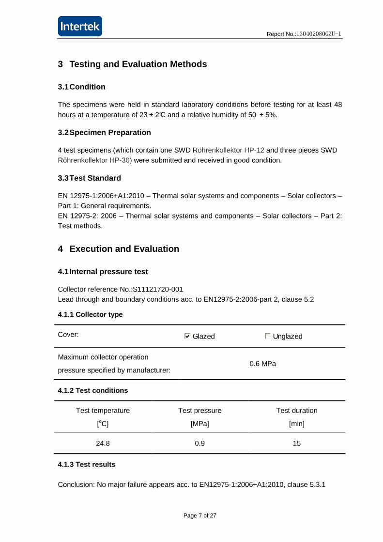
3 Testing and Evaluation Methods
3.1 Condition
The specimens were held in standard laboratory conditions before testing for at least 48
hours at a temperature of 23 ± 2°C and a relative humidity of 50 ± 5%.
3.2 Specimen Preparation
4 test specimens (which contain one SWD Röhrenkollektor HP-12 and three pieces SWD Röhrenkollektor HP-30) were submitted and received in good condition.
3.3 Test Standard
EN 12975-1:2006+A1:2010 – Thermal solar systems and components – Solar collectors – Part 1: General requirements. EN 12975-2: 2006 – Thermal solar systems and components – Solar collectors – Part 2: Test methods.
4 Execution and Evaluation
4.1 Internal pressure test
Collector reference No.:S11121720-001 Lead through and boundary conditions acc. to EN12975-2:2006-part 2, clause 5.2
4.1.1 Collector type
Cover: Glazed Unglazed
Maximum collector operation
pressure specified by manufacturer: 0.6 MPa
4.1.2 Test conditions
Test temperature
[oC]
Test pressure
[MPa]
Test duration
[min]
24.8 0.9 15
4.1.3 Test results
Conclusion: No major failure appears acc. to EN12975-1:2006+A1:2010, clause 5.3.1
Report No.:130402080GZU-1
Page 8 of 27
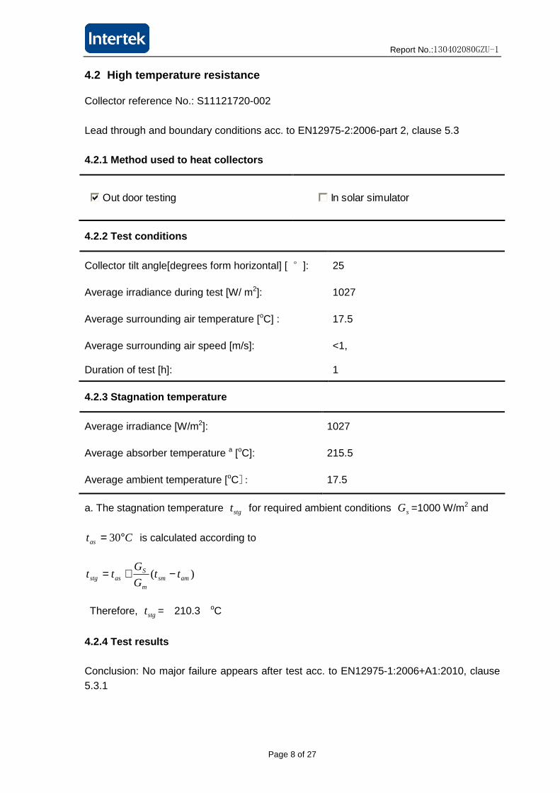
4.2 High temperature resistance
Collector reference No.: S11121720-002
Lead through and boundary conditions acc. to EN12975-2:2006-part 2, clause 5.3
4.2.1 Method used to heat collectors
Out door testing In solar simulator
4.2.2 Test conditions
Collector tilt angle[degrees form horizontal] [ °]: 25
Average irradiance during test [W/ m2]: 1027
Average surrounding air temperature [oC] : 17.5
Average surrounding air speed [m/s]: <1,
Duration of test [h]: 1
4.2.3 Stagnation temperature
Average irradiance [W/m2]: 1027
Average absorber temperature a [oC]: 215.5
Average ambient temperature [oC]: 17.5
a. The stagnation temperature stgt for required ambient conditions sG =1000 W/m2 and
Ctas °= 30 is calculated according to
)( amsmm
Sasstg tt
G
Gtt −+=
Therefore, stgt = 210.3 oC
4.2.4 Test results
Conclusion: No major failure appears after test acc. to EN12975-1:2006+A1:2010, clause 5.3.1

Report No.:130402080GZU-1
Page 9 of 27
4.3 Exposure test
Collector reference No.: S11121720-002
Lead through and boundary conditions acc. to EN12975-2:2006-part 2, clause 5.4
Collector tilt angle (degree from horizontal): 25°
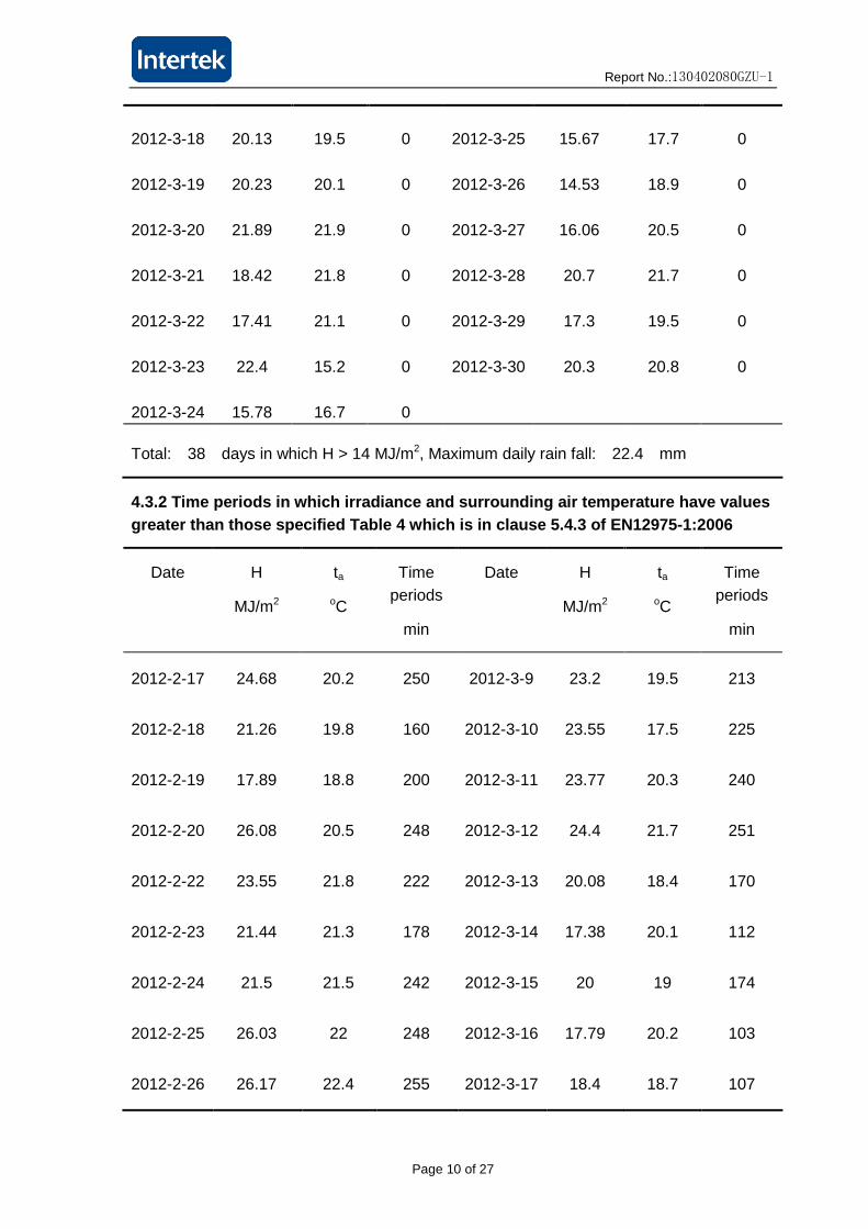
4.3.1 Climatic conditions for all days during the t est
Date H
(MJ/m2)
ta
(oC)
Rain
(mm)
Date H
(MJ/m2)
ta
(oC)
Rain
(mm)
2012-2-17 24.68 20.2 0 2012-3-3 3.7 9.9 22.4
2012-2-18 21.26 19.8 0 2012-3-4 16.2 13 0
2012-2-19 17.89 18.8 0 2012-3-5 25.1 15.5 0
2012-2-20 26.08 20.5 0 2012-3-6 19.4 15.7 0
2012-2-21 16.97 20.1 0 2012-3-7 15.3 16.9 0
2012-2-22 23.55 21.8 0 2012-3-8 11 17.9 0
2012-2-23 21.44 21.3 0 2012-3-9 23.2 19.5 0
2012-2-24 21.5 21.5 0 2012-3-10 23.55 17.5 0
2012-2-25 26.03 22 0 2012-3-11 23.77 20.3 0
2012-2-26 26.17 22.4 0 2012-3-12 24.4 21.7 0
2012-2-27 12.94 19.2 0 2012-3-13 20.08 18.4 0
2012-2-28 21.27 20.3 0 2012-3-14 17.38 20.1 0
2012-2-29 14.6 18.4 0 2012-3-15 20 19 0
2012-3-1 13.53 17.2 0 2012-3-16 17.79 20.2 0
2012-3-2 6.7 12.5 9.7 2012-3-17 18.4 18.7 0
Report No.:130402080GZU-1
Page 10 of 27
2012-3-18 20.13 19.5 0 2012-3-25 15.67 17.7 0
2012-3-19 20.23 20.1 0 2012-3-26 14.53 18.9 0
2012-3-20 21.89 21.9 0 2012-3-27 16.06 20.5 0
2012-3-21 18.42 21.8 0 2012-3-28 20.7 21.7 0
2012-3-22 17.41 21.1 0 2012-3-29 17.3 19.5 0
2012-3-23 22.4 15.2 0 2012-3-30 20.3 20.8 0
2012-3-24 15.78 16.7 0
Total: 38 days in which H > 14 MJ/m2, Maximum daily rain fall: 22.4 mm
4.3.2 Time periods in which irradiance and surround ing air temperature have values greater than those specified Table 4 which is in cl ause 5.4.3 of EN12975-1:2006
Date H
MJ/m2
ta
oC
Time periods
min
Date H
MJ/m2
ta
oC
Time periods
min
2012-2-17 24.68 20.2 250 2012-3-9 23.2 19.5 213
2012-2-18 21.26 19.8 160 2012-3-10 23.55 17.5 225
2012-2-19 17.89 18.8 200 2012-3-11 23.77 20.3 240
2012-2-20 26.08 20.5 248 2012-3-12 24.4 21.7 251
2012-2-22 23.55 21.8 222 2012-3-13 20.08 18.4 170
2012-2-23 21.44 21.3 178 2012-3-14 17.38 20.1 112
2012-2-24 21.5 21.5 242 2012-3-15 20 19 174
2012-2-25 26.03 22 248 2012-3-16 17.79 20.2 103
2012-2-26 26.17 22.4 255 2012-3-17 18.4 18.7 107

Report No.:130402080GZU-1
Page 11 of 27
2012-2-28 21.27 20.3 205 2012-3-20 21.89 21.9 187
2012-2-29 14.6 18.4 155 2012-3-21 18.42 21.8 163
2012-3-5 25.1 15.5 234 2012-3-22 17.41 21.1 93
2012-3-6 19.4 15.7 175 2012-3-23 22.4 15.2 218
2012-3-7 15.3 16.9 73 2012-3-24 15.78 16.7 124
2012-3-8 11 17.9 30 2012-3-25 15.67 17.7 45
2012-3-9 23.2 19.5 213 2012-3-26 14.53 18.9 113
2012-3-10 23.55 17.5 225 2012-3-27 16.06 20.5 70
2012-3-11 23.77 20.3 240 2012-3-28 20.7 21.7 142
2012-3-12 24.4 21.7 251 2012-3-29 17.3 19.5 113
2012-3-13 20.08 18.4 170 2012-3-30 20.3 20.8 136
2012-3-14 17.38 20.1 112
2012-3-15 20 19 174
2012-3-16 17.79 20.2 103
2012-3-17 18.4 18.7 107
2012-3-18 20.13 19.5 144
2012-3-19 20.23 20.1 107
Total time: 128.7 hours in which G > 850 W/m2

Report No.:130402080GZU-1
Page 12 of 27
4.3.3 Test Results
Conclusion: Evaluate each potential problem according to the following scale:
0 – No problem
1 – Minor problem
2 – Severe problem
* - Inspection to establish the condition was not possible
Collector component Potential problem evaluation Result
Collector box/fasteners Cracking/warping/corrosion/
rain penetration 0
Mounting/structure Strength/safety
0
Seals/gaskets Cracking/adhesion/elasticity
0
Cover/reflector Cracking/crazing/buckling/
delamination 0
Absorber coating Cracking/crazing/blistering
0
Absorber tubes and headers
Deformation/corrosion/leakage/
loss of bonding 0
Absorber mountings Deformation/corrosion
0
Insulation Water retention/outgassing/degradation 0
And there are no major failure appears after test acc. to EN12975-1:2006+A1:2010, clause 5.3.1.

Report No.:130402080GZU-1
Page 13 of 27
4.4 External thermal shock test
Collector reference No.: S11121720-002
Lead through and boundary conditions acc. to EN12975-2:2006-part 2, clause 5.5
4.4.1 Test conditions
Test performed outdoors Combined with exposure test
Test performed indoors in solar simulator
Combined with high temperature resistance test
First shock Second shock
Collector tilt angle[°] 25 25
Min & mean irradiance [W/m2] 981.5 992.2 904.5 915.6
Min & mean surrounding air temperature[oC] 18.0 18.4 16.6 17.1
Period during which the required operating
conditions were maintained prior to shock
[min]
60 60
Flow rate of water spray [kg/s﹒m2] 0.04 0.04
Temperature of water spray [oC] 17.5 17.3
Duration of water spray [min] 15 15
Absorber temperature immediately prior to
water spray [oC]
Not detected Not detected
4.4.2 Test results
Conclusion: No major failure appears after test acc. to EN12975-1:2006+A1:2010, clause 5.3.1

Report No.:130402080GZU-1
Page 14 of 27
4.5 Internal thermal shock test
Collector reference No.: S11121720-002
Lead through and boundary conditions acc. to EN12975-2:2006-part 2, clause 5.6
4.5.1 Test conditions
Test performed outdoors Combined with exposure test
Test performed indoors in solar simulator
Combined with high temperature resistance test
First shock Second shock
Collector tilt angle[°] 25 25
Min & mean irradiance [W/m2] 916.8 940.0 1018.6 1031.4
Min & mean surrounding air temperature[oC] 17.3 18.4 15.7 16.0
Period during which the required operating
conditions were maintained prior to shock
[min]
60 60
Flow rate of heat transfer fluid [kg/s﹒m2] 0.04 0.04
Temperature of heat transfer fluid [oC] 17.2 16.4
Duration of heat transfer fluid flow [min] 5 5
Absorber temperature immediately prior to
heat transfer fluid flow [oC]
Not detected Not detected
4.5.2 Test results
Conclusion: No major failure appears after test acc. to EN12975-1:2006+A1:2010, clause 5.3.1

Report No.:130402080GZU-1
Page 15 of 27
4.6 Rain penetration
Collector reference No.: S11121720-002
Lead through and boundary conditions acc. to EN12975-2:2006-part 2, clause 5.7
4.6.1 Test conditions
Collect mounted on:
Open frame Simulated roof
Collector tilt angle[°]: 30
Collector experienced exposure days: 25 days
Method used to keep absorber warm: □ Hot water circulation
■ Exposure of collector to solar radiation
Water spray flow rate[kg/(s﹒m2)]: 0.05
Water temperature[oC]: 19.5
Duration of water spray [h]: 4
4.6.2 Test results
Area with visible sign of water penetration
[expressed as a percentage of aperture area]
--
Give details of water penetration, reporting
the place where water penetrated
--
The time the sign of rain penetration took to vanish --
Collector weight before test [g]: 91795
Collector weight after test [g]: 91830
And no major failure appears after test acc. to EN12975-1:2006+A1:2010, clause 5.3.1

Report No.:130402080GZU-1
Page 16 of 27
4.7 Freeze resistance test (NA)
Collector reference No.:--
Lead through and boundary conditions acc. to EN12975-2:2006-part 2, clause 5.8
4.7.1 Collector type and tilt angle
Freeze-resistant when filled with water Drain down
Tilt angle of collector during test [°]:
4.7.2 Test conditions
Freeze conditions Thaw conditions No. of
freeze-thaw
cycles
Test
temperature[oC]
Duration
[min]
Test
temperaturea[oC]
Duration
[min]
1 -- -- -- --
2 -- -- -- --
3 -- -- -- --
a For freeze-resistant collectors, this is the temperature of the contents of the collector,
e.g. water, ice
For drain-down collectors, this is the temperature measured inside the absorber close to
the inlet
Rate of chamber cooling [K/h]: --
Rate of chamber cooling[K/h]: --
4.7.3 Test results Give details of leakage, breakage, distortion or deformation and any of the failures denoting ‘’major failure’’, defined in 5.3.1 of EN12975-1:2006+A1:2010

Report No.:130402080GZU-1
Page 17 of 27
4.8 Mechanical load test
Lead through and boundary conditions acc. to EN12975-2:2006-part 2, clause 5.9
4.8.1 Positive pressure test of the collector cover Collector reference No.: S11121720-001 4.8.1.1 Method used to apply pressure
Loading with gravel or similar material Loading with water
Suction cups Pressurization of collector cover
4.8.1.2 Test condition
Maximum pressure load [Pa]: 2500
4.8.1.3 Test result
Conclusion: The test pressure was increased to 2500Pa with one tube broken acc. to EN12975-1:2006+A1:2010, clause 5.3.1.
4.8.2 Negative pressure test of fixing between the cover and the collector box (NA) Collector reference No.: -- 4.8.2.1 Method used to apply pressure
Suction cups Pressurization of collector box
4.8.2.2 Test condition
Maximum pressure load [Pa]: -- Pa
4.8.2.3 Test result
Conclusion: --
NOTE: Not relevant on vacuum tubes for this test NA.

Report No.:130402080GZU-1
Page 18 of 27
4.9 Impact resistance test using steel balls (NA)
Collector reference No.:--
Lead through and boundary conditions acc. to EN12975-2:2006-part 2, clause 5.9
4.9.1 Test conditions
Diameter of ball [mm]: --
Mass of ball [g]: --
Test performed by using: Vertical impact Horizontal impact
4.9.2 Test procedure
Drop height [m]
No. of drops
-- --
-- --
-- --
-- --
-- --
-- --
-- --
-- --
-- --
4.9.3 Test result
Conclusion: --

Report No.:130402080GZU-1
Page 19 of 27
4.10 Final inspection results
Evaluate each potential problem according to the following scale:
0 – No problem
1 – Minor problem
2 – Severe problem
* - Inspection to establish the condition was not possible
Collector component Potential problem evaluation Result
Collector box/fasteners Cracking/warping/corrosion/
rain penetration
0
Mounting/structure Strength/safety 0
Seals/gaskets Cracking/adhesion/elasticity 0
Cover/reflector Cracking/crazing/buckling/
delamination 0
Absorber coating Cracking/crazing/blistering 0
Absorber tubes and headers
Deformation/corrosion/leakage/
loss of bonding
0
Absorber mountings Deformation/corrosion 0
Insulation Water retention/outgassing/degradation
0

Report No.:130402080GZU-1
Page 20 of 27
5 Test results of thermal performance
Collector reference No.: S11121720-003/004
5.1 Test method according to EN 12975-2:2006
Outdoor-Steady State Method(6.1) Indoor-Steady State Method(6.2)
Outdoor-Quasi-Dynamic Method(6.3)
5.2 Test conditions
Collector model: SWD
Röhrenkollektor HP-12
SWD Röhrenkollektor
HP-30
Latitude [°]: North 23.08 North 23.08
Longitude [°]: East 113.15 East 113.15
Mass flow [kg/(s m2)]: 0.02 0.02
Aperture area [m2]: 1.14 2.84
Collector absorber area [m2]: 0.98 2.44
The instantaneous efficiency is defined by: AGQ /=η
5.3 Test results of thermal performance
Collector model: SWD
Röhrenkollektor HP-12
SWD Röhrenkollektor
HP-30
Effective heat capacity c [kJ/(m2K)]: 12.15
Incident angle modifier Kө (50): 0.90 0.91
Peak power [ peakW ] per collector unit
(G=1000 W/(m2K), am tt − =0) [W]: 814 1999
Determination of power output per collector unit (second order fit to data):

Report No.:130402080GZU-1
Page 21 of 27
−−
−−⋅=
⋅ 2
210G
ttGa
G
ttaGAQ amamη
Coefficient based on aperture area
SWD Röhrenkollektor HP-12 SWD Röhrenkollektor HP-30
a0η 0.714 '0aη 0.704
aa1 1.078 '1aa 1.406
aa2 0.037 '2aa 0.020
Power output per collect SWD Röhrenkollektor HP-12
SWD Röhrenkollektor HP-30
Irradiance am tt − [k]
400 W/m2 700 W/m2 1000 W/m2
0 326 570 814
10 309 553 797
30 251 495 739
50 159 403 647
70 33 277 521
Irradiance am tt − [k]
400 W/m2 700 W/m2 1000 W/m2
0 800 1400 1999
10 754 1354 1954
30 629 1229 1828
50 458 1058 1658
70 242 842 1442

Report No.:130402080GZU-1
Page 22 of 27
Figure 5.1 Power output per collector unit (for G=1 000W/m2)
Incident angle modifier SWD Röhrenkollektor HP-12
IAM at ө 0o 10o 20o 30o 40o 50o 60o 70o 80o 90o
Transversal: 1.00 1.09 1.25 1.44
Longitudinal: 1.00 0.90
SWD Röhrenkollektor HP-30
IAM at ө 0o 10o 20o 30o 40o 50o 60o 70o 80o 90o
Transversal: 1.00 1.07 1.18 1.32
Longitudinal: 1.00 0.91

Report No.:130402080GZU-1
Page 23 of 27
Pressure drop ( SWD Röhrenkollektor HP-30)
0
200
400
600
800
1000
1200
0 0.02 0.04 0.06 0.08 0.1
Flow rate [kg/s]
Pre
ssur
e dr
op [P
a]
Figure 5.2 Pressure drop of the collector SWD R öhrenkollektor HP-30 (for 19.5 oC water)

Report No.:130402080GZU-1
Page 24 of 27
Annex A
Measured data
G Gd’ m tin te te-tin tm ta (tm-ta)/G
(W/m2) (W/m2) (kg/s. m2) (0C) (0C) (0C) (0C) (0C) (Km2/W) η
SWD Röhrenkollektor HP-12 990 122 0.0197 22.69 31.24 8.55 26.97 24.61 0.00238 0.7123
1007 121 0.0199 22.68 31.24 8.56 26.96 24.57 0.00237 0.7064 999 120 0.0199 22.68 31.25 8.57 26.97 24.68 0.00229 0.7144 993 119 0.0197 22.71 31.32 8.61 27.02 24.13 0.00291 0.7148
1008 124 0.0199 41.13 49.42 8.28 45.27 26.81 0.01832 0.6856 1008 127 0.0200 41.13 49.38 8.25 45.26 27.20 0.01792 0.6834 1009 127 0.0200 41.14 49.38 8.25 45.26 27.14 0.01797 0.6828 1019 127 0.0200 41.13 49.37 8.24 45.25 27.83 0.01710 0.6753 919 187 0.0200 60.28 67.04 6.76 63.66 27.81 0.03903 0.6167 916 186 0.0200 60.32 67.11 6.79 63.72 27.89 0.03911 0.6214 907 194 0.0200 60.30 67.06 6.76 63.68 28.21 0.03912 0.6229 905 200 0.0200 60.29 67.03 6.74 63.66 28.15 0.03923 0.6220 849 195 0.0199 80.42 85.68 5.25 83.05 27.90 0.06498 0.5138 847 197 0.0199 80.51 85.72 5.22 83.11 27.65 0.06547 0.5112 859 198 0.0199 80.49 85.77 5.28 83.13 28.06 0.06409 0.5122 872 197 0.0200 80.43 85.75 5.32 83.09 27.95 0.06321 0.5086
SWD Röhrenkollektor HP-30 1031 124 0.0200 15.49 24.21 8.72 19.85 16.72 0.00304 0.7061 1035 126 0.0201 15.50 24.14 8.64 19.82 16.09 0.00361 0.7027 1039 124 0.0200 15.53 24.17 8.64 19.85 16.68 0.00306 0.6968 1040 124 0.0200 15.49 24.15 8.66 19.82 16.26 0.00342 0.6957 1009 115 0.0200 36.85 44.84 7.98 40.85 19.37 0.02128 0.6613 1011 114 0.0201 36.88 44.80 7.92 40.84 18.65 0.02194 0.6580 1011 112 0.0201 36.85 44.82 7.96 40.83 18.68 0.02191 0.6607 1010 114 0.0200 36.84 44.75 7.91 40.79 17.98 0.02260 0.6564 975 110 0.0200 58.50 65.49 6.99 61.99 19.25 0.04383 0.6005 966 110 0.0200 58.51 65.53 7.03 62.02 19.90 0.04361 0.6095 959 110 0.0203 58.48 65.44 6.96 61.96 20.39 0.04333 0.6176 955 110 0.0201 58.49 65.44 6.95 61.96 19.80 0.04415 0.6107 909 114 0.0200 80.73 86.22 5.48 83.48 18.60 0.07138 0.5062 914 120 0.0200 80.73 86.26 5.54 83.50 18.71 0.07089 0.5084 899 126 0.0200 80.73 86.31 5.58 83.52 18.65 0.07214 0.5217 901 130 0.0200 80.75 86.19 5.44 83.47 18.33 0.07233 0.5074
Note: The diffuse irradiance has been modified based on the diffuse irradiance pyranometer shade ring.

Report No.:130402080GZU-1
Page 25 of 27
Annex B
Terms and definitions
Symbol Term Unit
A Area (aperture, gross or absorber) m2
0η Zero-loss collector efficiency -
a0η Zero-loss collector efficiency based on aperture area -
'0aη Zero-loss collector efficiency based on aperture area -
Q Useful power extracted from the collector W G Solar irradiance W/ m2 tm Mean temperature of heat transfer fluid oC ta Ambient air temperature oC a1 Heat transfer coefficient W/ m2/K a1a Heat transfer coefficient based on aperture area W/ m2/K a1a’ Heat transfer coefficient based on aperture area W/ m2/K a2 Temperature depending heat transfer coefficient W/ m2/K2 a2a Temperature depending heat transfer coefficient based
on aperture area W/ m2/K2
a2a’ Temperature depending heat transfer coefficient based on aperture area
W/ m2/K2
m Mass flow kg/s tin Collector inlet temperature oC te Collector outlet temperature oC
Measuring uncertainties
Thermal performance: ±3.1%
Irradiance: ±2.8%
Temperature water: ±0.05K
Temperature air: ±0.25K
Water flow: ±0.1%
Air speed: ±0.3m/s
Aperture: ±0.2%
Mass: ±2.9g

Report No.:130402080GZU-1
Page 26 of 27
Annex C
Photos
Figure- C.1: Photo of internal pressure test
Figure- C.2: Photo of positive pressure test

Report No.:130402080GZU-1
Page 27 of 27
REVISION SUMMARY
INTERTEK INITIALS
DATE SECTION SUMMARY TECHNICIAN REVIEWER