Embed Size (px)
Citation preview
This report is for the exclusive use of Intertek's Client and is provided pursuant to the agreement between Intertek and its Client. Intertek's responsibility and liability are limited to the terms and conditions of the agreement. Intertek assumes no liability to any party, other than to the Client in accordance with the agreement, for any loss, expense or damage occasioned by the use of this report. Only the Client is authorized to copy or distribute this report and then only in its entirety. Any use of the Intertek name or one of its marks for the sale or advertisement of the tested material, product or service must first be approved in writing by Intertek. The observations and test results in this report are relevant only to the sample tested. This report by itself does not imply that the material, product, or service is or has ever been under an Intertek certification program.
1
REPORT NUMBER: 100397303SAT-002 ORIGINAL ISSUE DATE: April 28, 2011
REVISED DATE: N/A
EVALUATION CENTER 16015 Shady Falls Road
Elmendorf, TX 78112 Phone: (210) 635-8100
Fax: (210) 635-8101 www.intertek.com
RENDERED TO
CANADIAN HOME BUILDERS ASSOCIATION EDMONTON REGION
150 SUMMERSIDE GATE SW EDMONTON AB T6X 0P5
PRODUCT EVALUATED: Exterior Wall Assemblies with Wood Framed Windows
EVALUATION PROPERTY: Heat Flux through Target Wall Windows TE
ST
RE
PO
RT
Report of Testing Exterior Wall Assemblies with Wood Framed Windows for compliance with the applicable requirements of the following criteria: Client Specified Test Procedure
Canadian Home Builders Association April 28, 2011 Project No. 100397303SAT-002 Page 2 of 176
1 Table of Contents 1 Table of Contents..................................................................................................................2
2 Introduction ...........................................................................................................................3
3 Test Samples ........................................................................................................................3
3.1. SAMPLE SELECTION ..................................................................................................3
3.2. SAMPLE AND ASSEMBLY DESCRIPTION .................................................................3
4 Testing and Evaluation Methods...........................................................................................4
4.1. INSTRUMENTATION....................................................................................................4
4.2. TEST STANDARD ........................................................................................................4
5 Testing and Evaluation Results.............................................................................................4
5.1. RESULTS AND OBSERVATIONS TEST A ..................................................................4
5.2. RESULTS AND OBSERVATIONS TEST B ..................................................................5
5.3. RESULTS AND OBSERVATIONS TEST C ..................................................................5
5.4. RESULTS AND OBSERVATIONS TEST D ..................................................................6
6 Conclusion ............................................................................................................................7
APPENDIX A ................................................................................................................................8
APPENDIX B ..............................................................................................................................16
APPENDIX C ..............................................................................................................................18
APPENDIX D ..............................................................................................................................20
APPENDIX E ..............................................................................................................................38
APPENDIX F...............................................................................................................................56
APPENDIX G ..............................................................................................................................74
APPENDIX H ..............................................................................................................................92
List of Calibrated Instrumentation Used for Testing..................................................................174
Referenced Report....................................................................................................................175
REVISION SUMMARY .............................................................................................................176
Canadian Home Builders Association April 28, 2011 Project No. 100397303SAT-002 Page 3 of 176
2 Introduction Intertek Testing Services NA (Intertek) has conducted testing for Canadian Home Builders Association, on exterior wall construction with wood framed windows, to evaluate the heat flux exposure through windows from a neighboring building. Testing was conducted in accordance with the client supplied test procedure adapted from NRC-CNRC Full-Scale Fire Study of Spatial Separation, Research Report: IRC-RR-195, Dated May 19, 2005. This evaluation began April 20, 2011 and was completed April 22, 2011.
3 Test Samples
3.1. SAMPLE SELECTION
Samples were submitted to Intertek directly from the client. Samples were not independently selected for testing. Samples were received at the Evaluation Center on April 19, 2011.
3.2. SAMPLE AND ASSEMBLY DESCRIPTION
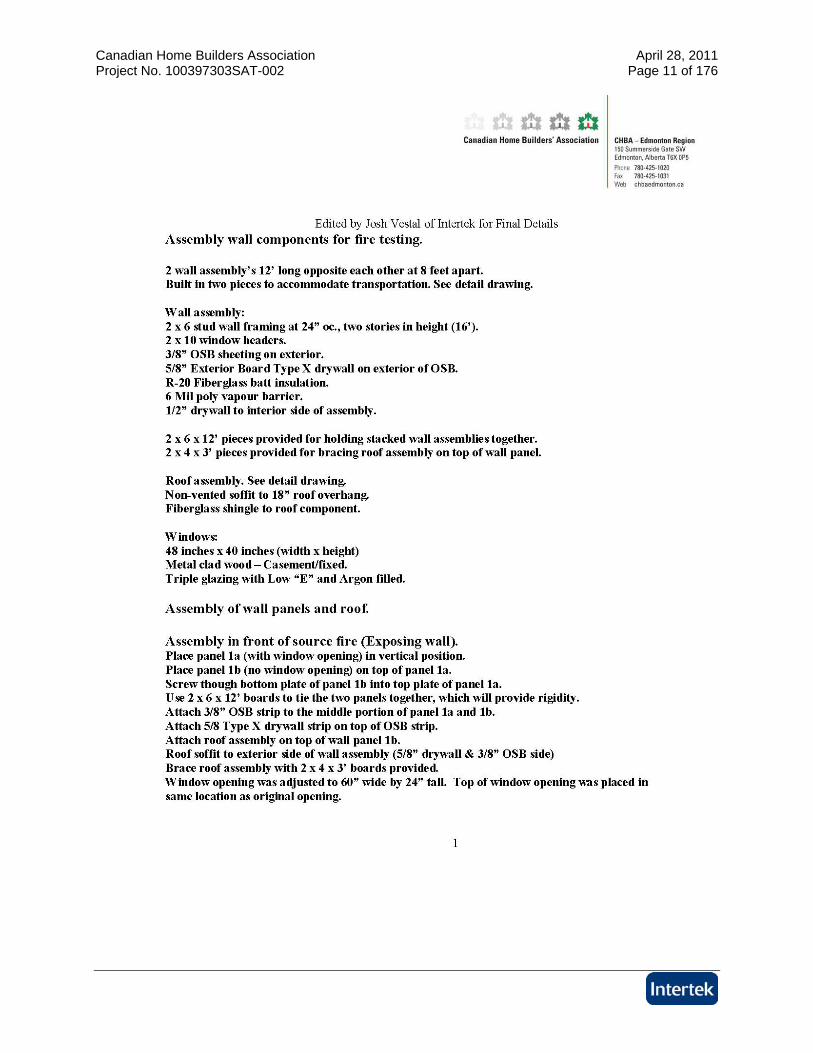
Sample wall assemblies were provided pre-manufactured by the client. Each wall assembly was provided in three parts and was assembled onsite by Intertek personnel. Each test consisted of an exposing wall and a target wall. A full description of the wall construction can be found in Appendix A. A brief description of the differences in the walls can be found in the chart below: Wall Wall Opening Stud Cavity Insulation
Exposing Wall 48” x 40” wood framed window
R-20 Fiberglass insulation Test A
Target Wall Two (2) 48” x 40” wood framed window
R-20 Fiberglass insulation
Exposing Wall 48” x 40” wood framed window
R-20 Fiberglass insulation Test B
Target Wall Same Target Wall as Test A (New windows installed)
Same Target Wall as Test A
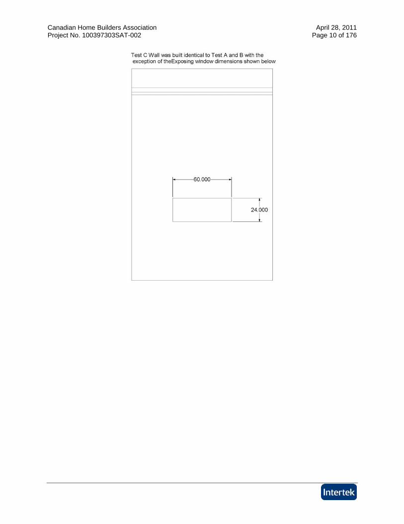
Exposing Wall 60” x 24” (No glass in opening)
R-20 Fiberglass insulation Test C
Target Wall Same Target Wall as Test A (New windows installed)
Same Target Wall as Test A
Exposing Wall 48” x 40” wood framed window
Nominal 2 pcf Polyurethane Spray Foam
Test D
Target Wall Two (2) 48” x 40” wood framed window
Nominal 2 pcf Polyurethane Spray Foam
In each test, the walls were spaced with 8’ of separation.
Canadian Home Builders Association April 28, 2011 Project No. 100397303SAT-002 Page 4 of 176
4 Testing and Evaluation Methods
4.1. INSTRUMENTATION
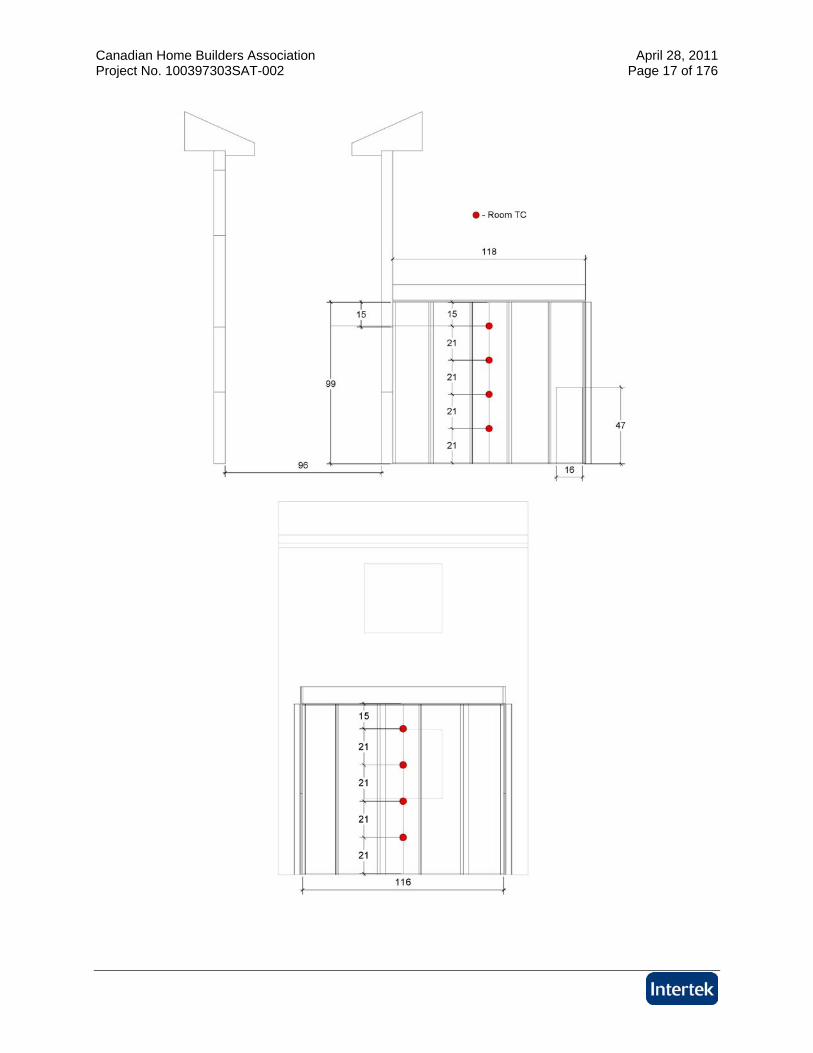
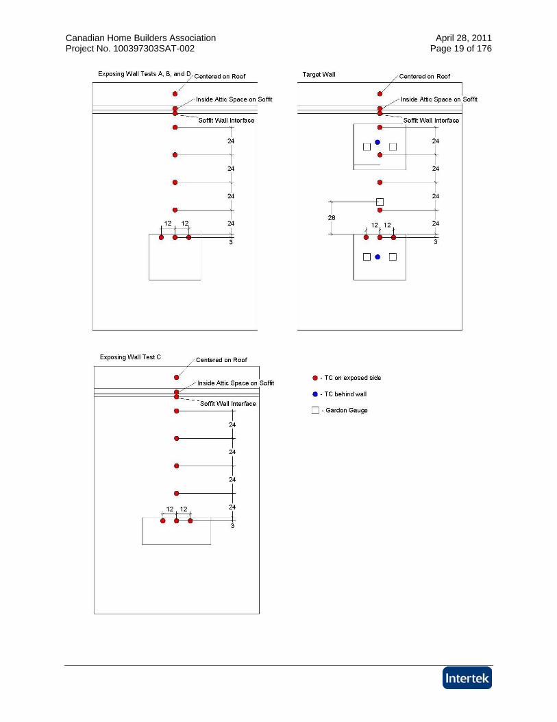
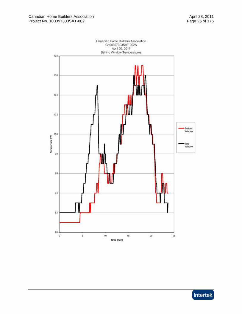
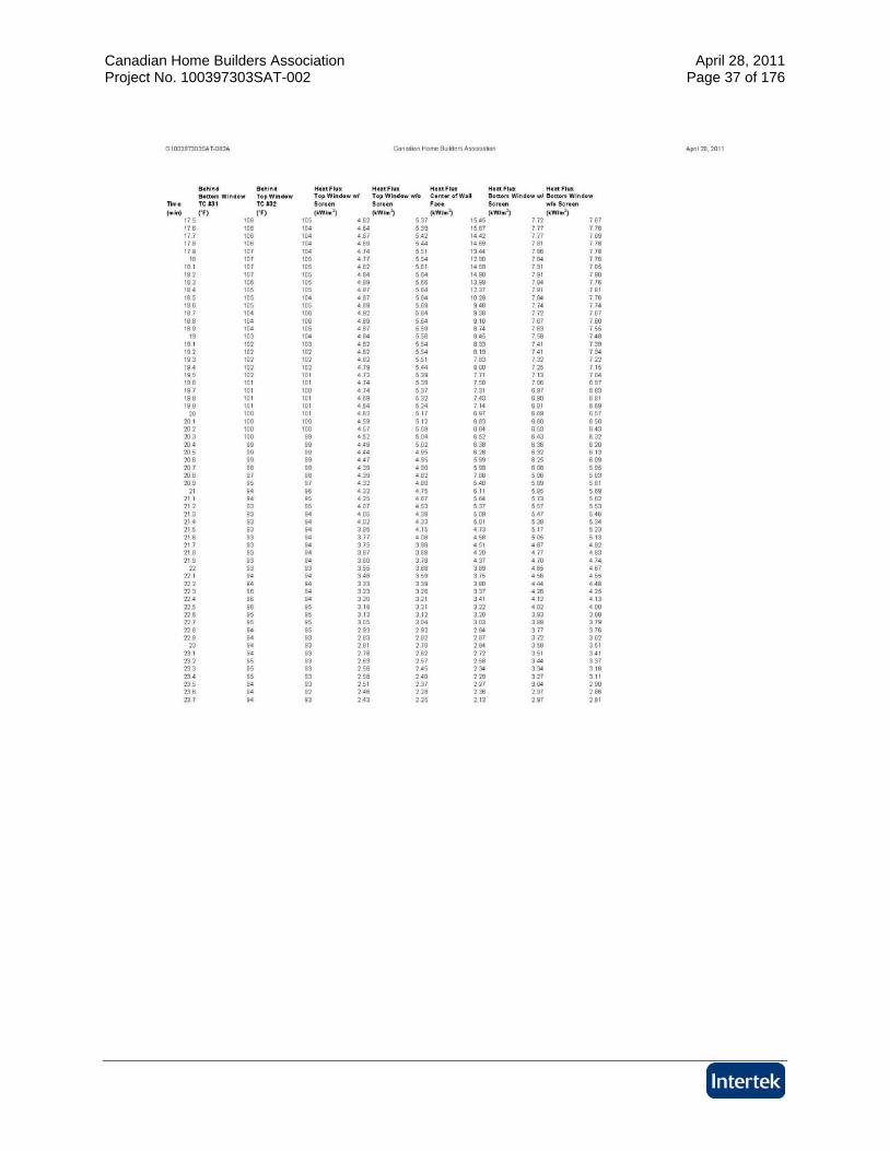
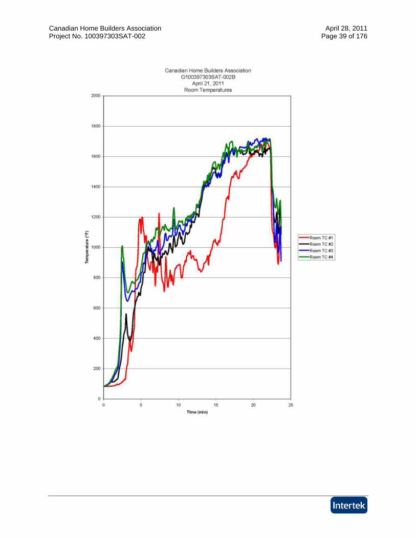
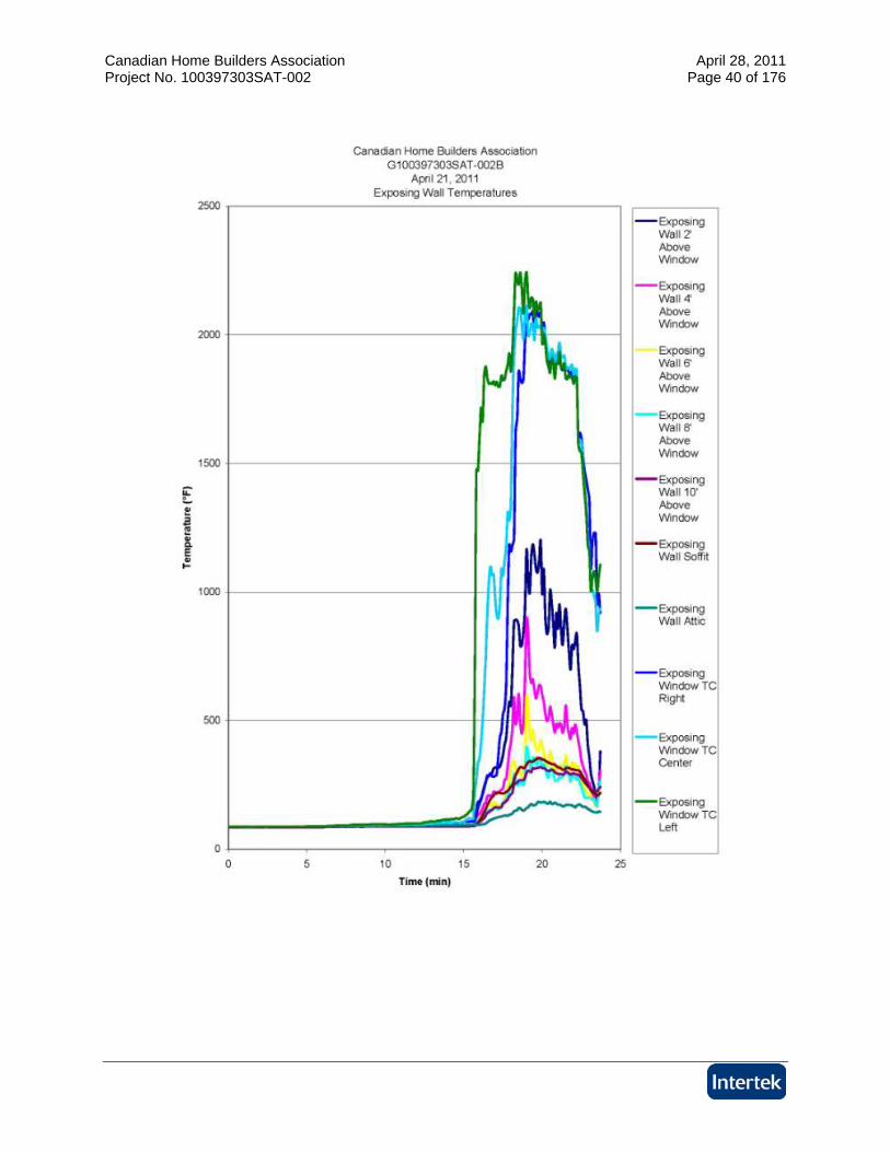
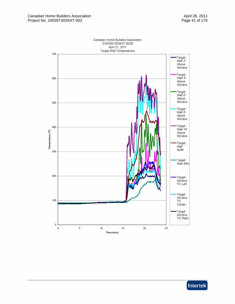
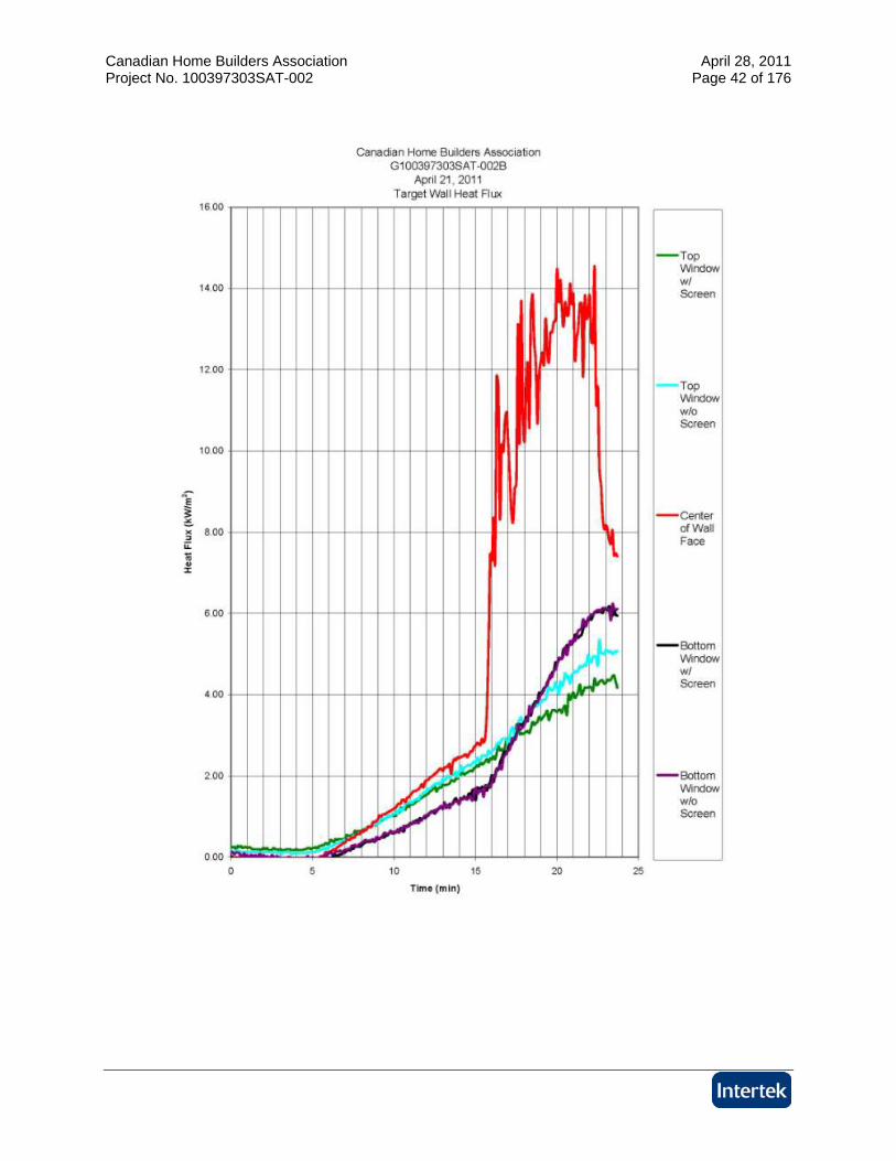
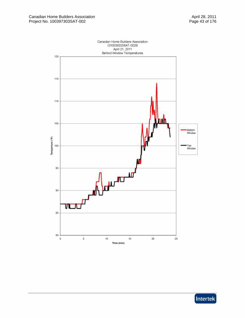
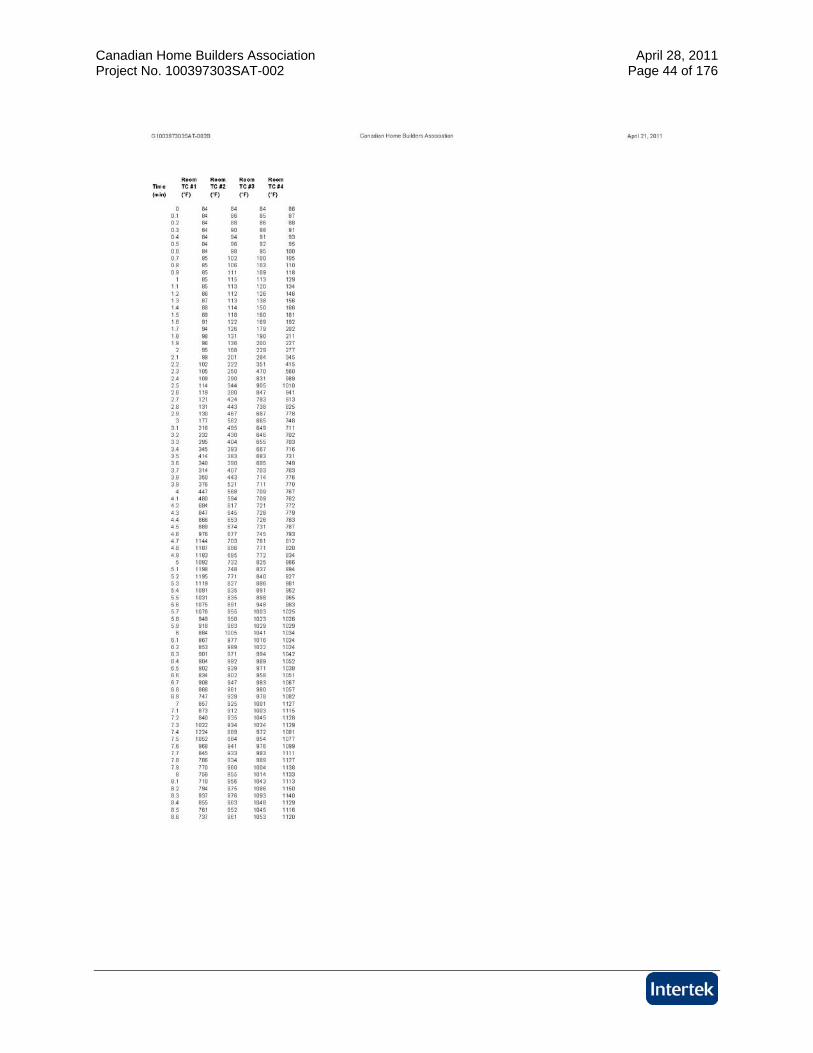
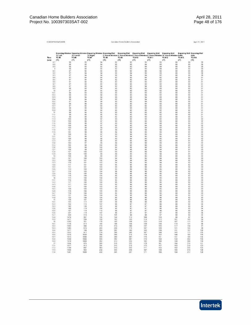
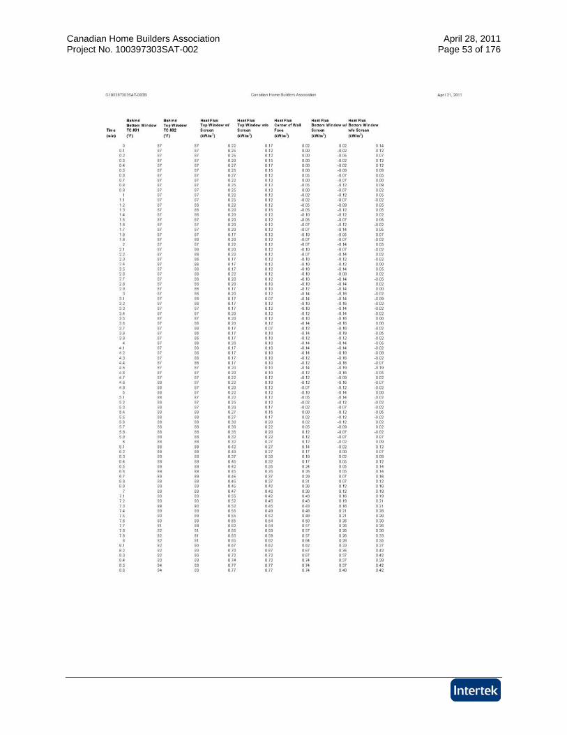
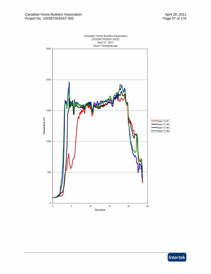
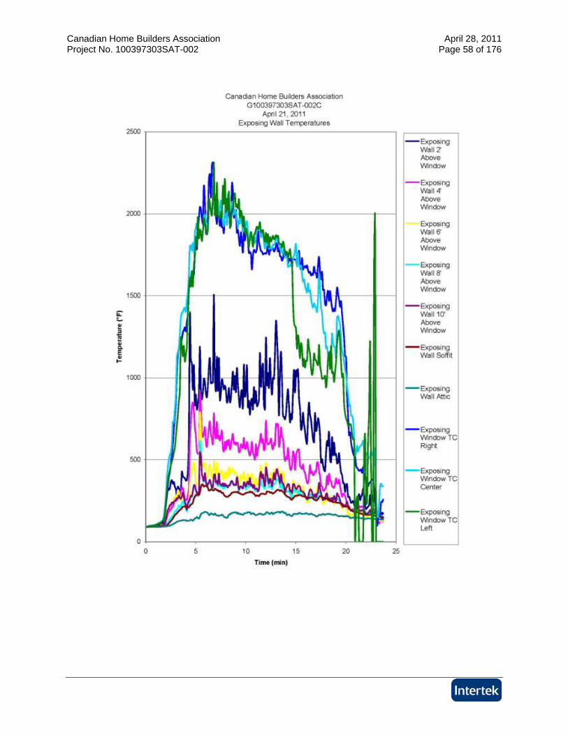
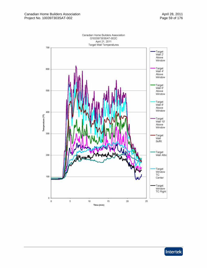
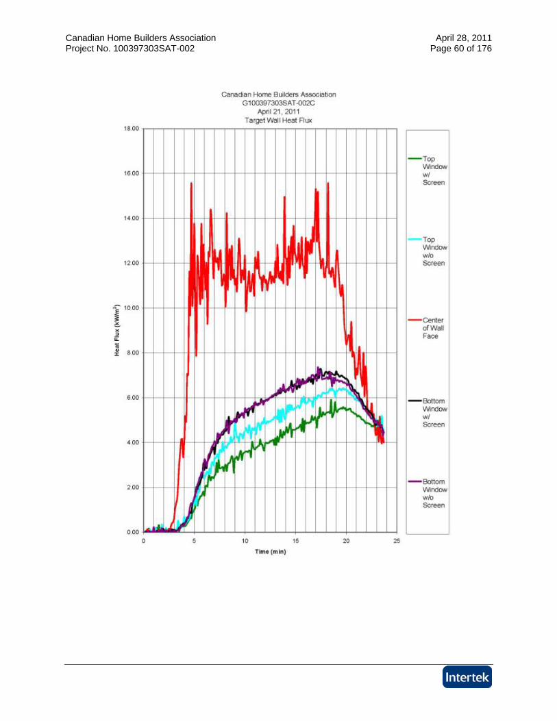
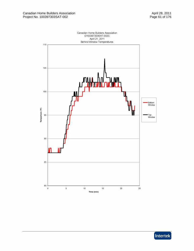
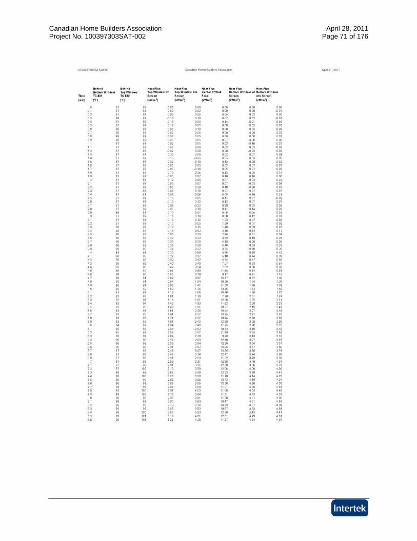
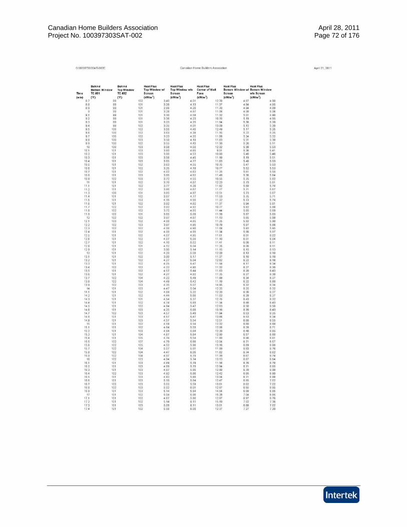
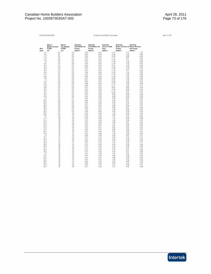
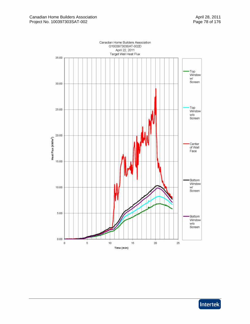
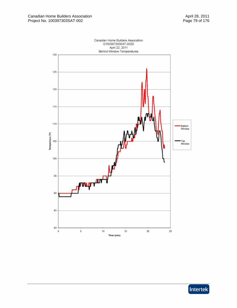
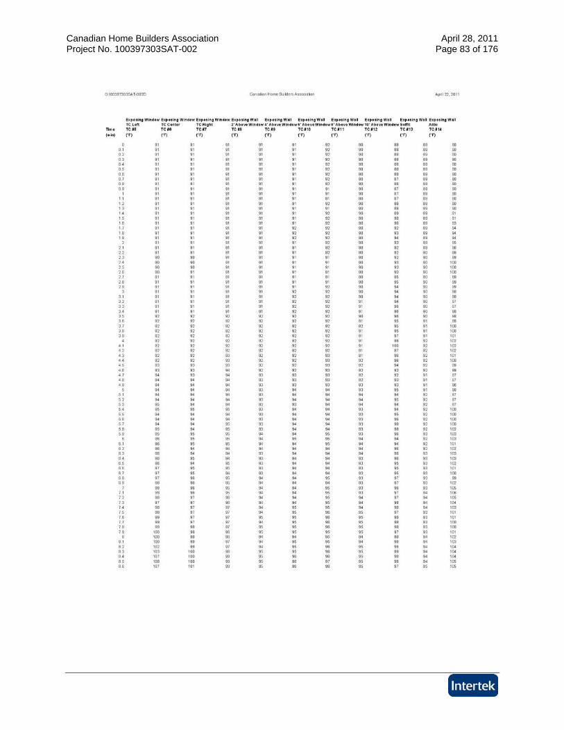
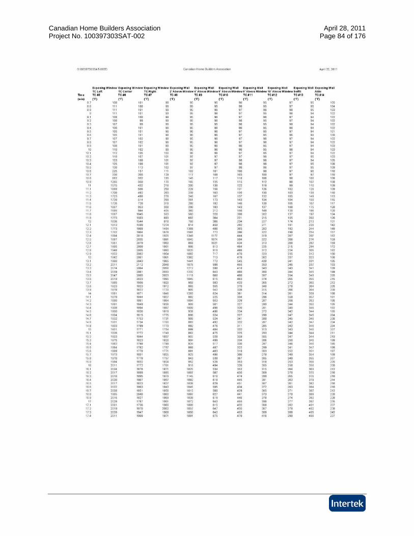
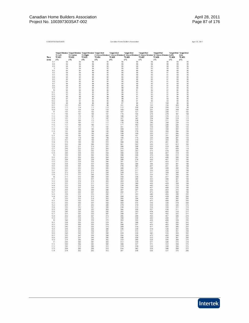
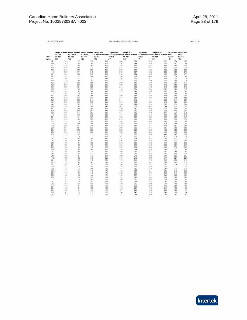
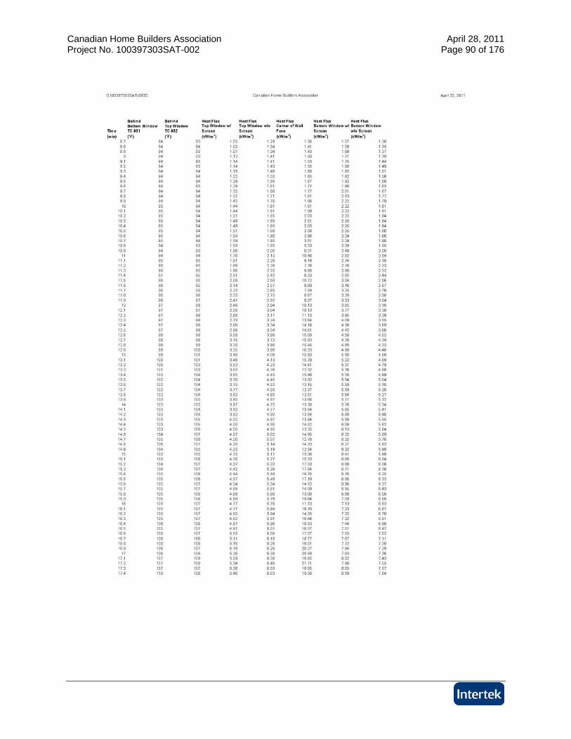
The fire compartment room was instrumented with four (4) thermocouples located at the center of the room spaced as seen in Appendix B. Each wall was instrumented with a total of ten (10) thermocouples as illustrated in Appendix C. The target Wall was instrumented with an additional two (2) thermocouples located behind each of the windows. The target wall was also instrumented with five (5) Gardon Gauges to measure heat flux. One (1) Gardon gauge was placed at the horizontal center of the wall, 112” from the bottom of the target wall, flush with the exposed surface of the wall. Each window pane in the target wall was instrumented with a Gardon gauge centered in the window pane on the unexposed side of the window flush with the unexposed surface of the wall (5-1/2” from window pane without screen, 6” from window pane with screen).
4.2. TEST STANDARD
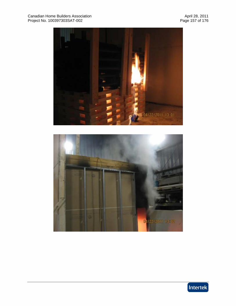
The testing was performed to the specifications provided by the client and intended to replicate the testing described in the referenced test report, NRC-CNRC Full-Scale Fire Study of Spatial Separation, Research Report: IRC-RR-195, Dated May 19, 2005 with the modifications described in this document. Details of the test setup can be found in Appendix A. Details of instrumentation can be found in Appendix B and Appendix C. Each test consisted of an exposing wall and a target wall as described in Section 3 and Appendix A of this document. The exposing wall was integrated with a fire compartment room. The fire compartment room dimensions can be found in Appendix B. For each test a fuel load consisting of 100 kg of 2 x 4 SPF lumber was cut and arranged in the form of two (2) cribs. An additional fuel load of 50 kg of ABS pipe was also cut and arranged as cribs on top of the two lumber cribs. The cribs were centered in the fire compartment room. Two (2) small steel pans filled with a total of 600 ml of alcohol were used as an accelerant.
5 Testing and Evaluation Results
5.1. RESULTS AND OBSERVATIONS TEST A
The test was initiated on April 20, 2011. Mark Turner, representing Landmark Group, and Brian Kobialka representing All Weather Windows, were present to witness the test. The test was initiated with the ignition of the accelerant. Observations made during the test are listed below: Time (min:sec) Observations from the Fire Exposure
0:00 The test was initiated at 9:11 A.M. with the ignition of the accelerant 1:00 Abs pipe igniting 3:00 Heavy smoke from room openings
Canadian Home Builders Association April 28, 2011 Project No. 100397303SAT-002 Page 5 of 176
4:20 Cracking noises from exposing window 4:45 Flames from room openings
10:45 Glass broke in exposing window 11:00 Fames from exposing window 18:00 Test terminated
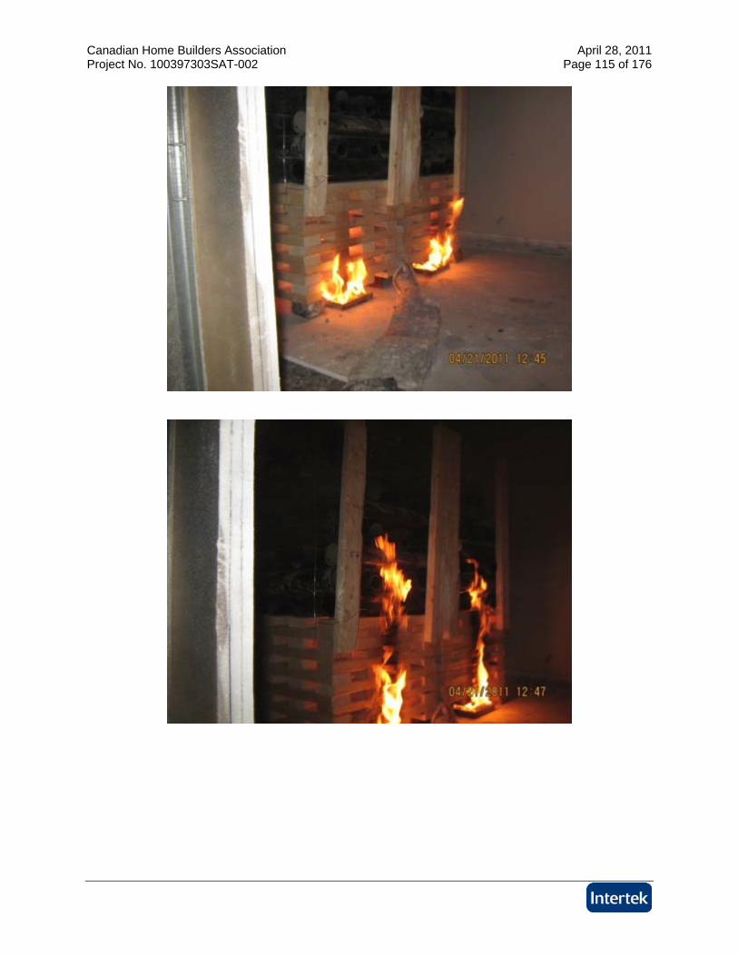
5.2. RESULTS AND OBSERVATIONS TEST B
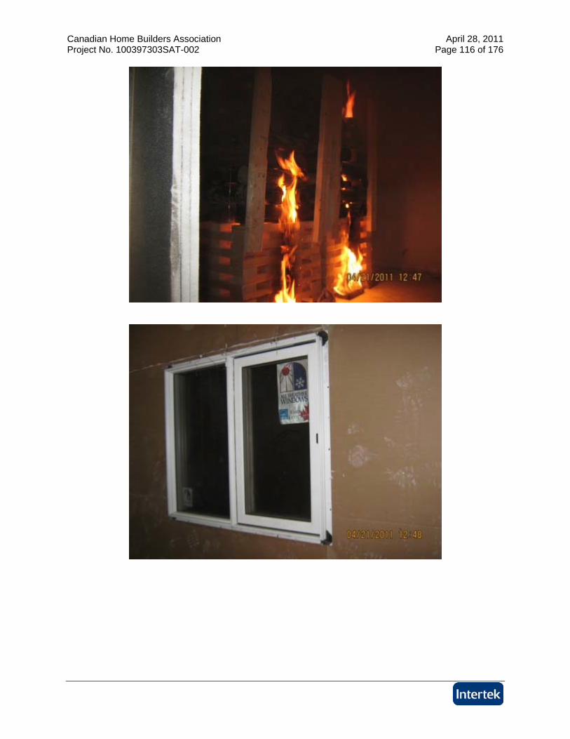
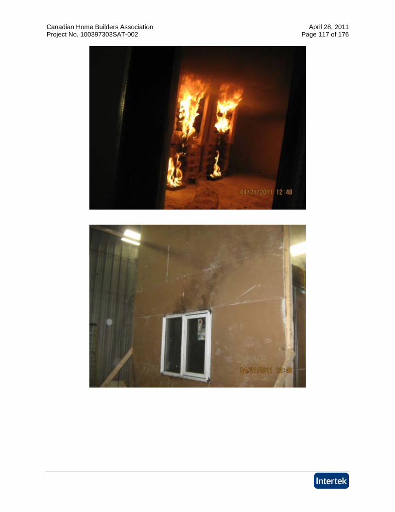
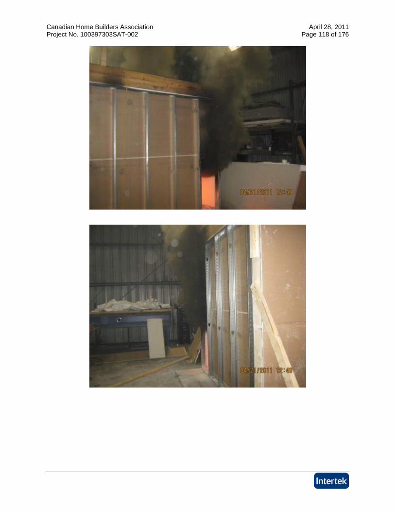
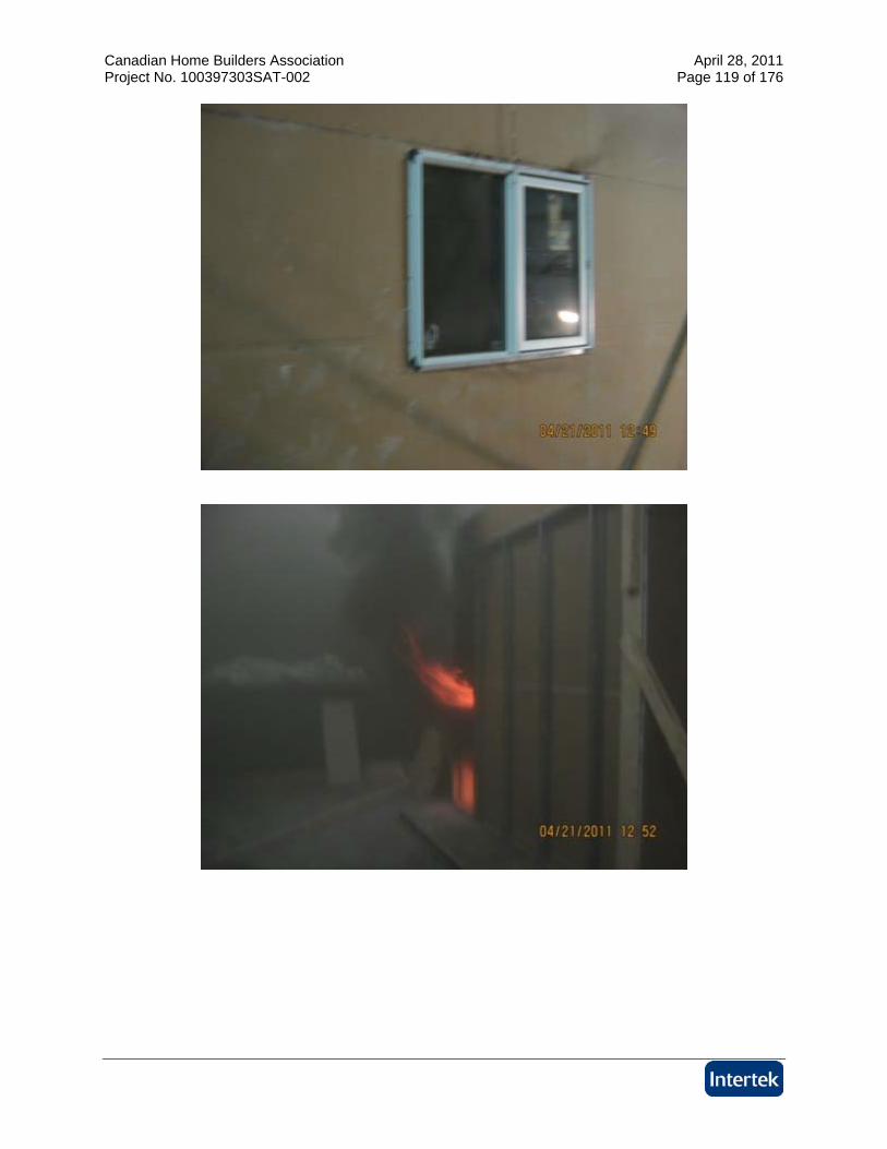
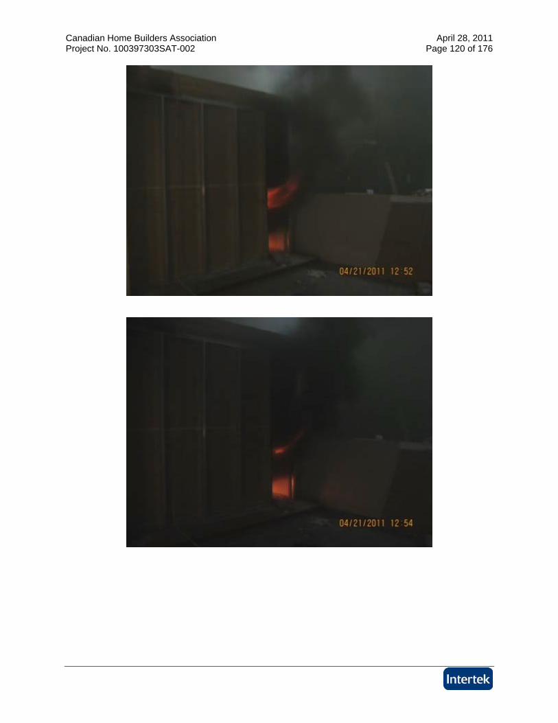
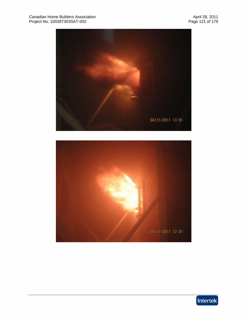
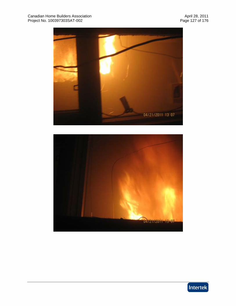
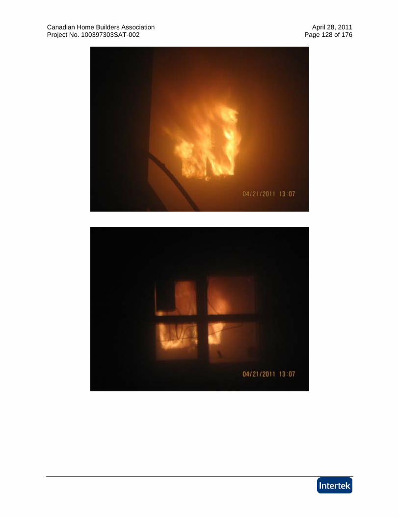
The test was initiated on April 21, 2011. Mark Turner, representing Landmark Group, and Brian Kobialka representing All Weather Windows, were present to witness the test. The test was initiated with the ignition of the accelerant. Observations made during the test are listed below: Time (min:sec) Observations from the Fire Exposure
0:00 The test was initiated at 12:45 P.M. with the ignition of the accelerant 1:30 ABS pipe melting and igniting 3:00 Heavy smoke from room openings and from the corners of the exposing
window 5:45 Heavy smoke continues to emit from room openings 6:00 Flames from room openings
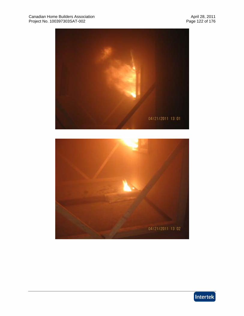
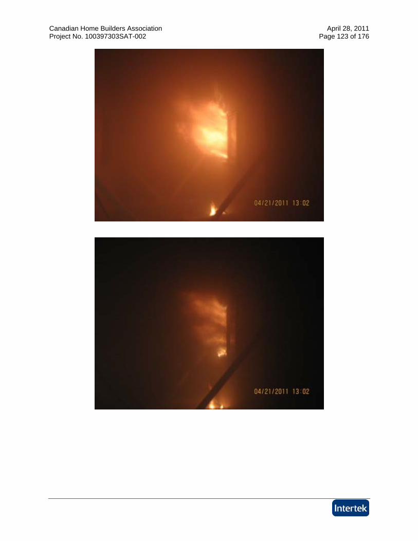
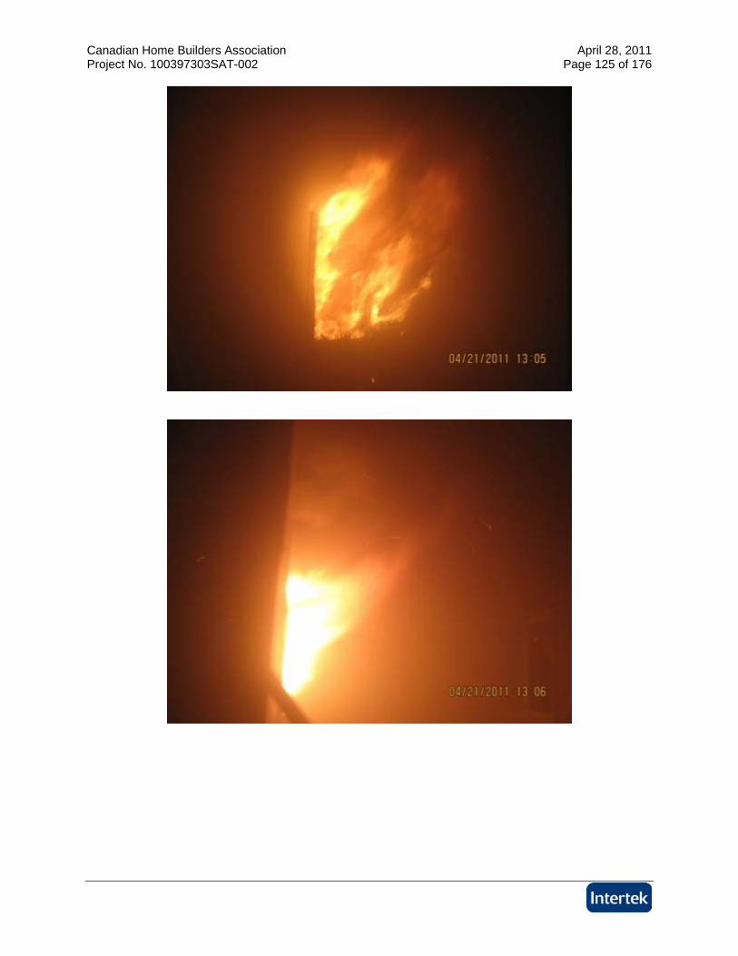
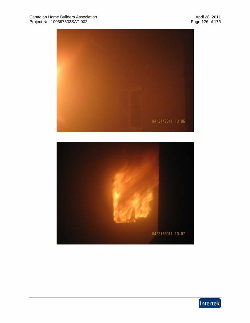
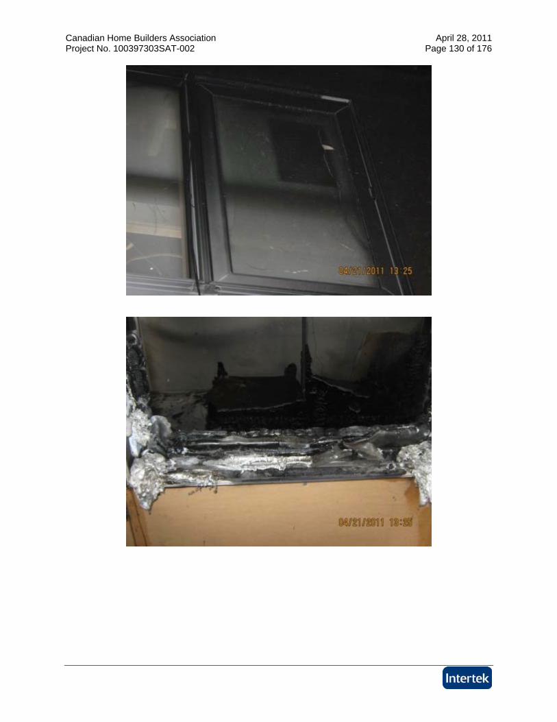
10:10 Cracking sounds from exposing window 15:45 Glass on exposing window broke and flames are coming out the window 22:00 Test terminated
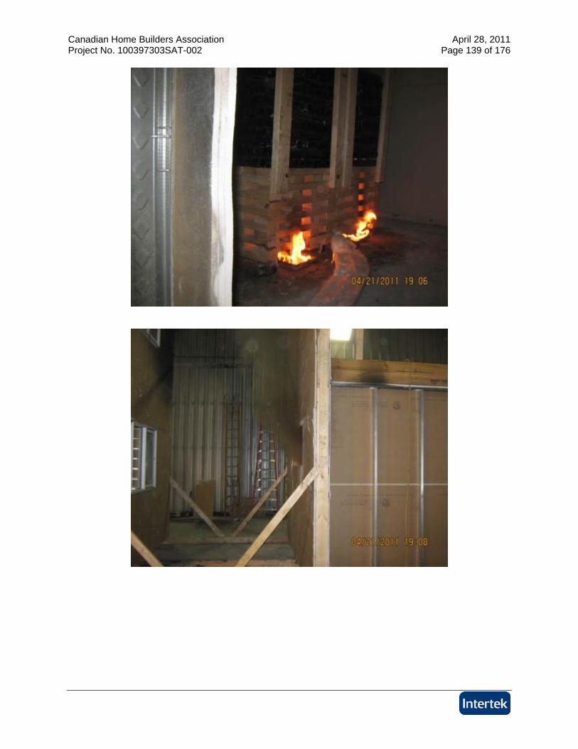
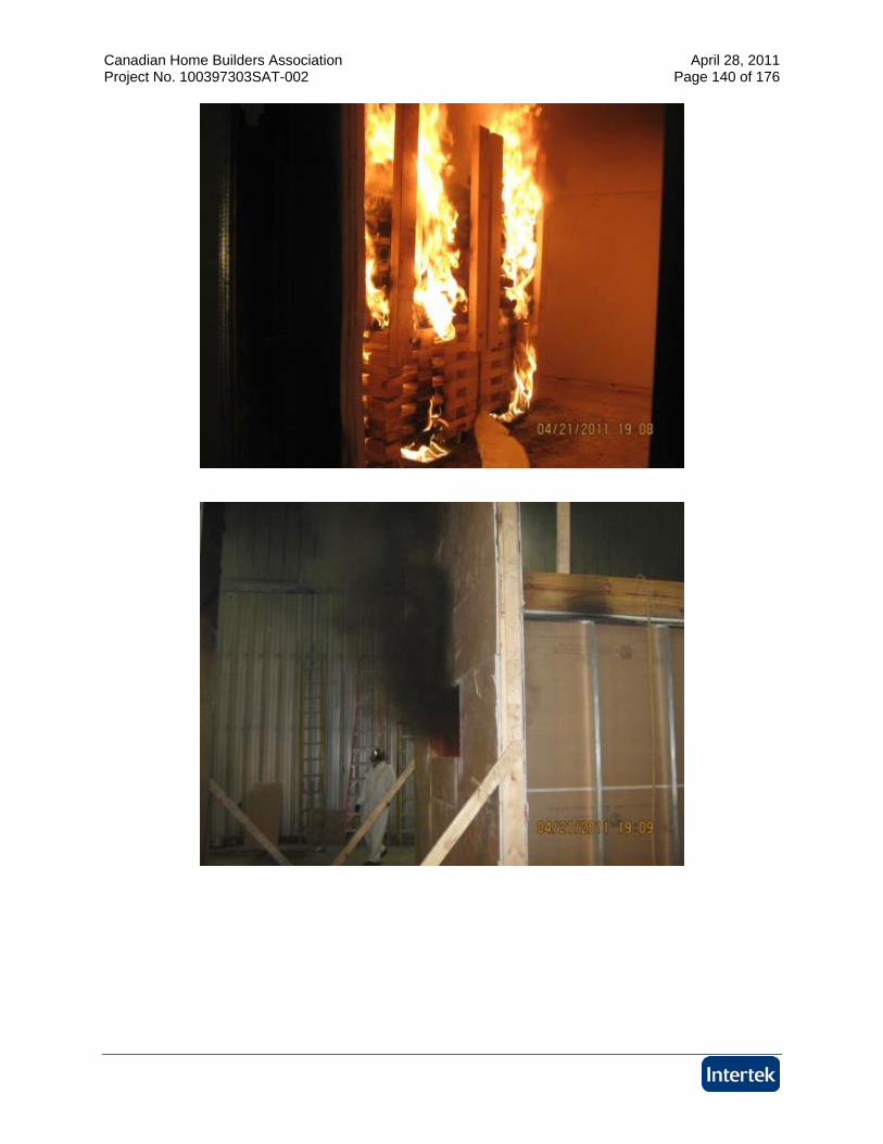
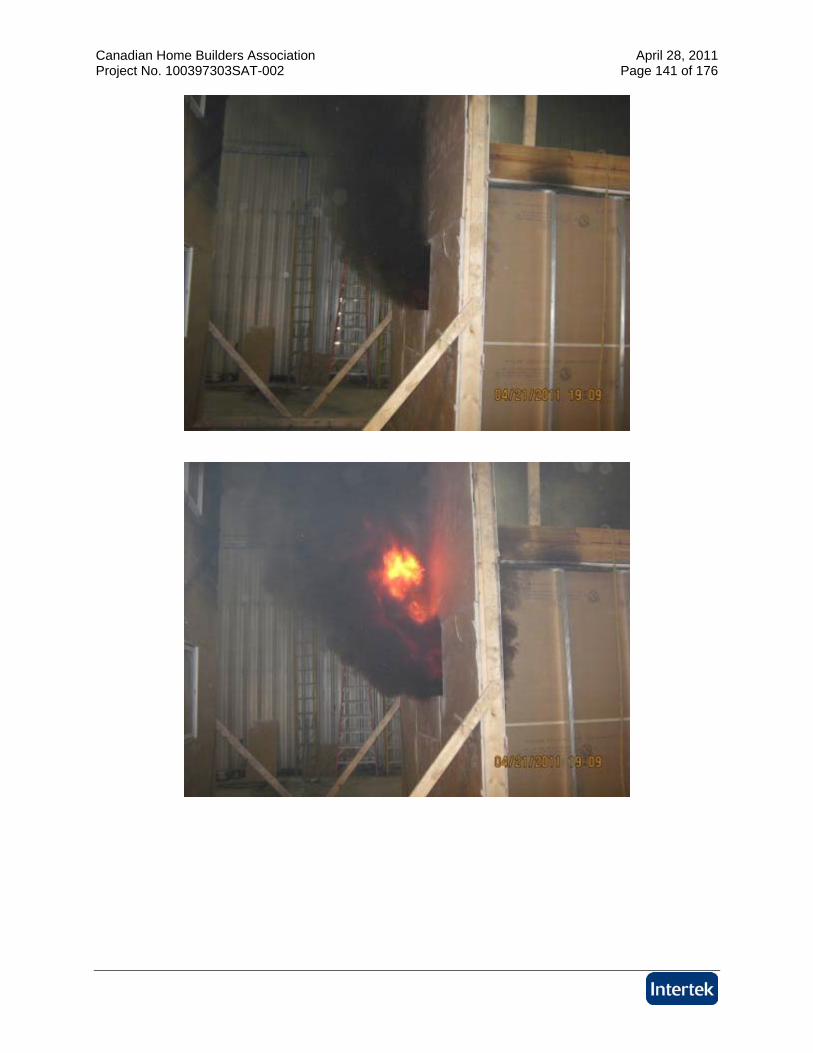
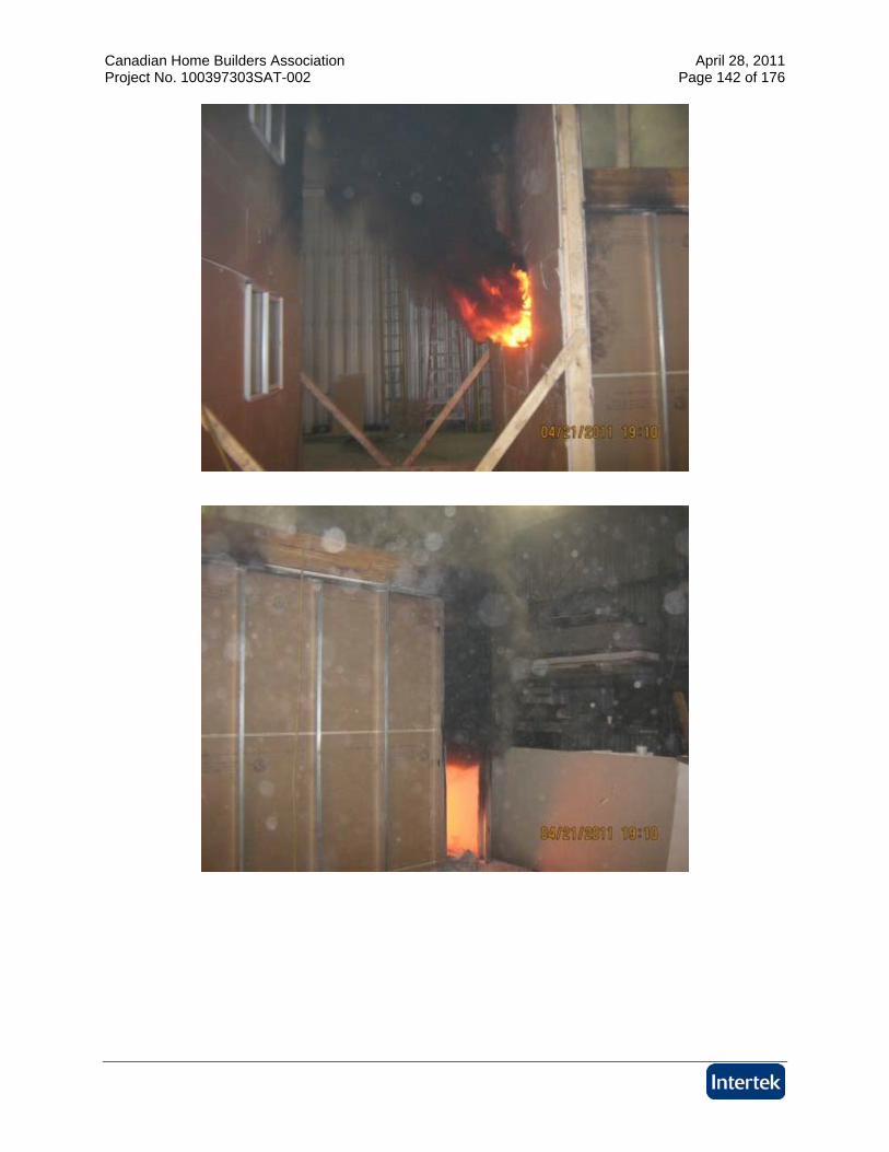
5.3. RESULTS AND OBSERVATIONS TEST C
The test was initiated on April 21, 2011. Mark Turner, representing Landmark Group, and Brian Kobialka representing All Weather Windows, were present to witness the test. The test was initiated with the ignition of the accelerant. Observations made during the test are listed below: Time (min:sec) Observations from the Fire Exposure
0:00 The test was initiated at 5:06 P.M. with the ignition of the accelerant 1:20 Smoke emitting from the exposing window 2:20 ABS is ignited 3:00 Flame tips are out the window 3:10 Heavy flaming out the window 4:15 Flame spreading up exposing wall and igniting gypsum paper. Flame tips
reaching target wall 5:00 Gypsum paper has burnt off exposing wall 6’ above window 7:00 Exterior window pane on lower target wall window has cracked 8:30 Smoke has lightened in color
12:30 Gypsum in fire compartment room has fallen off part of ceiling

Canadian Home Builders Association April 28, 2011 Project No. 100397303SAT-002 Page 6 of 176
15:20 Fiberglass insulation has fallen out exposing window 19:00 Test terminated
5.4. RESULTS AND OBSERVATIONS TEST D
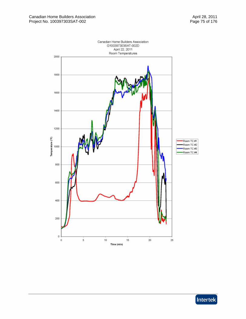
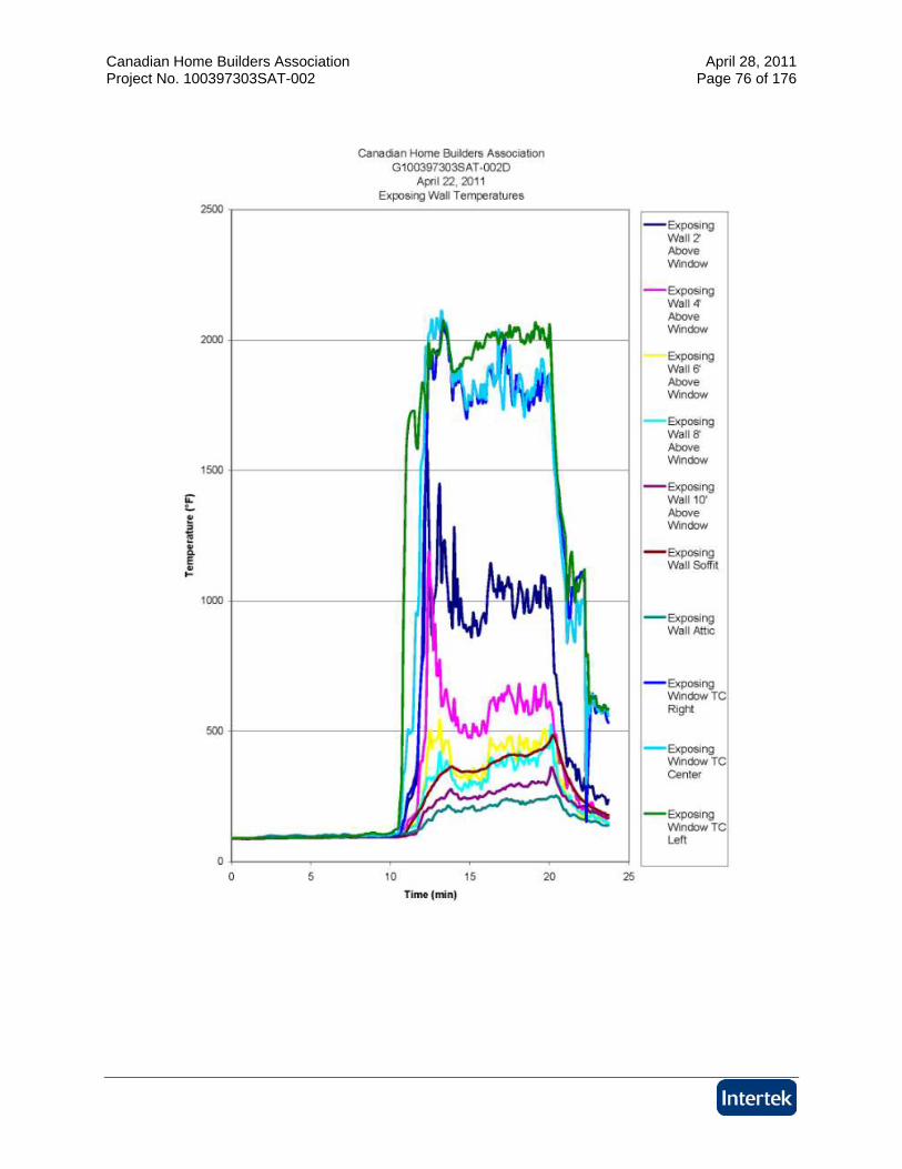
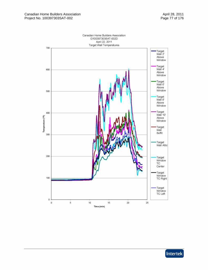
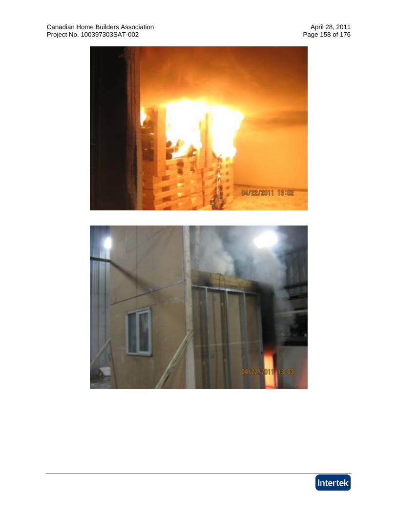
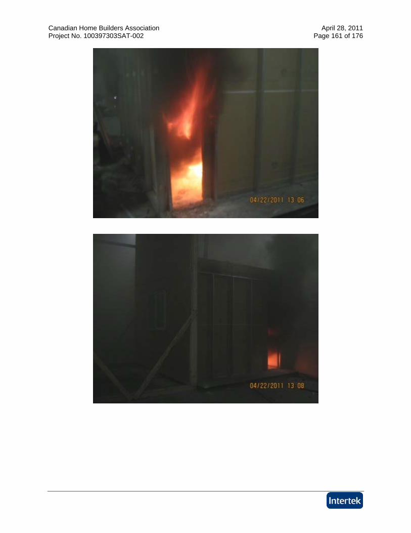
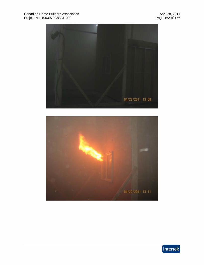
The test was initiated on April 22, 2011. Mark Turner, representing Landmark Group, and Brian Kobialka representing All Weather Windows, were present to witness the test. The test was initiated with the ignition of the accelerant. Observations made during the test are listed below: Time (min:sec) Observations from the Fire Exposure
0:00 The test was initiated at 12:56 P.M with the ignition of the accelerant 0:50 Smoke from room openings 1:10 Exposing window glass has discolored 2:22 Exposing window glass cracking 2:42 Exposing window glass cracking more 2:55 Black smoke emitting from around window frame 4:30 Exposing window continues to crack 5:30 Smoke density increasing 6:00 Flames from the room openings
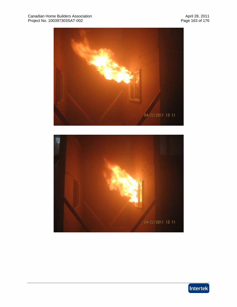
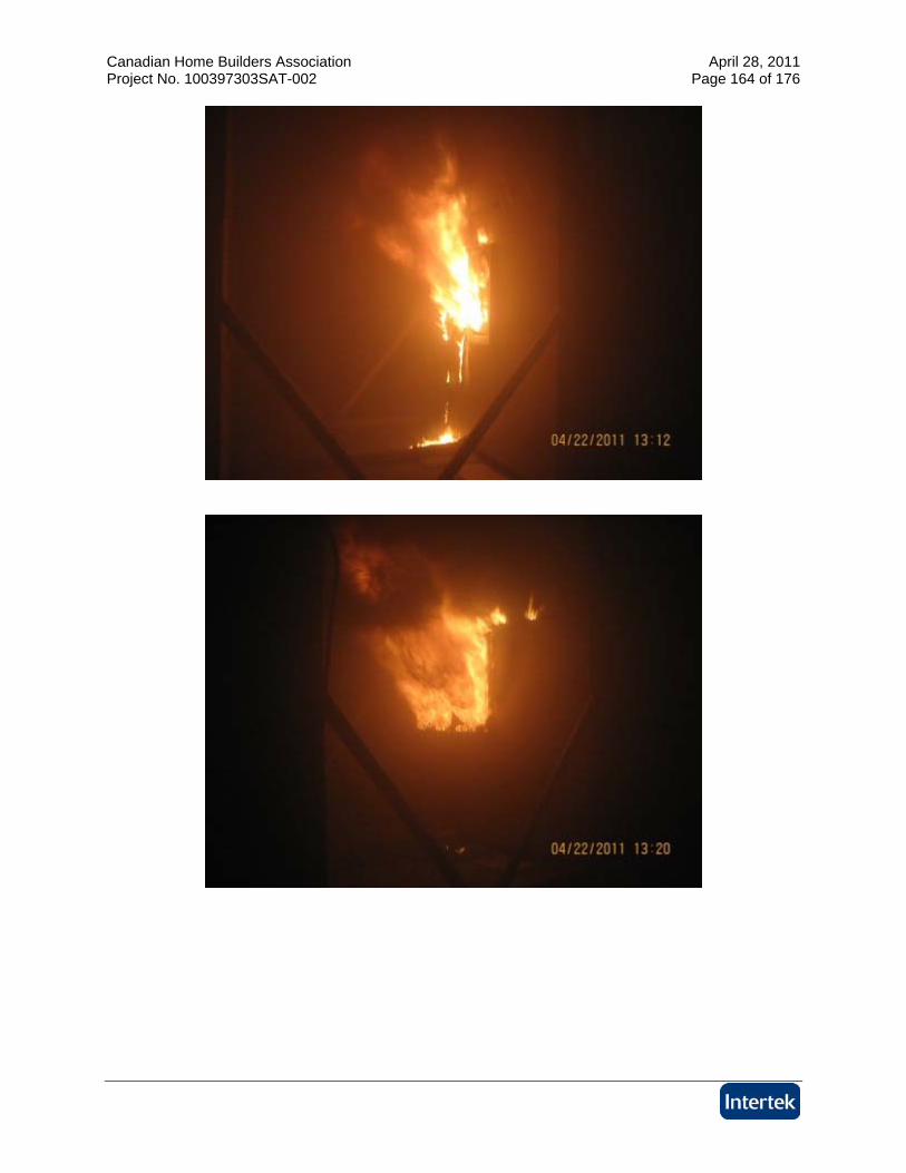
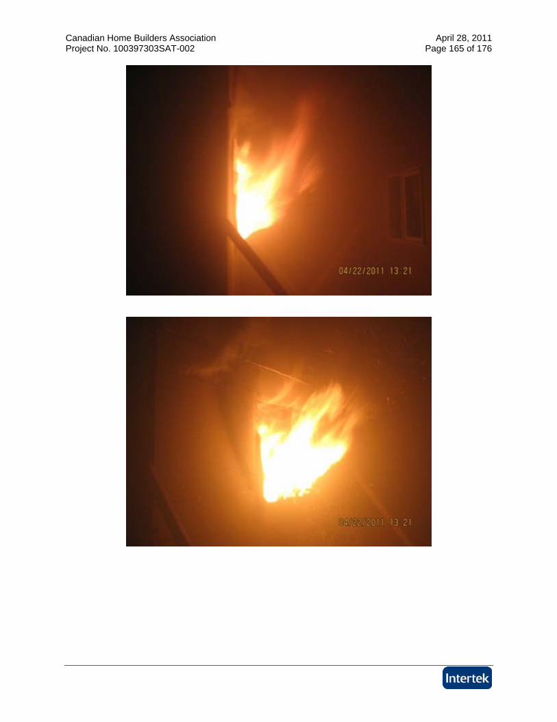
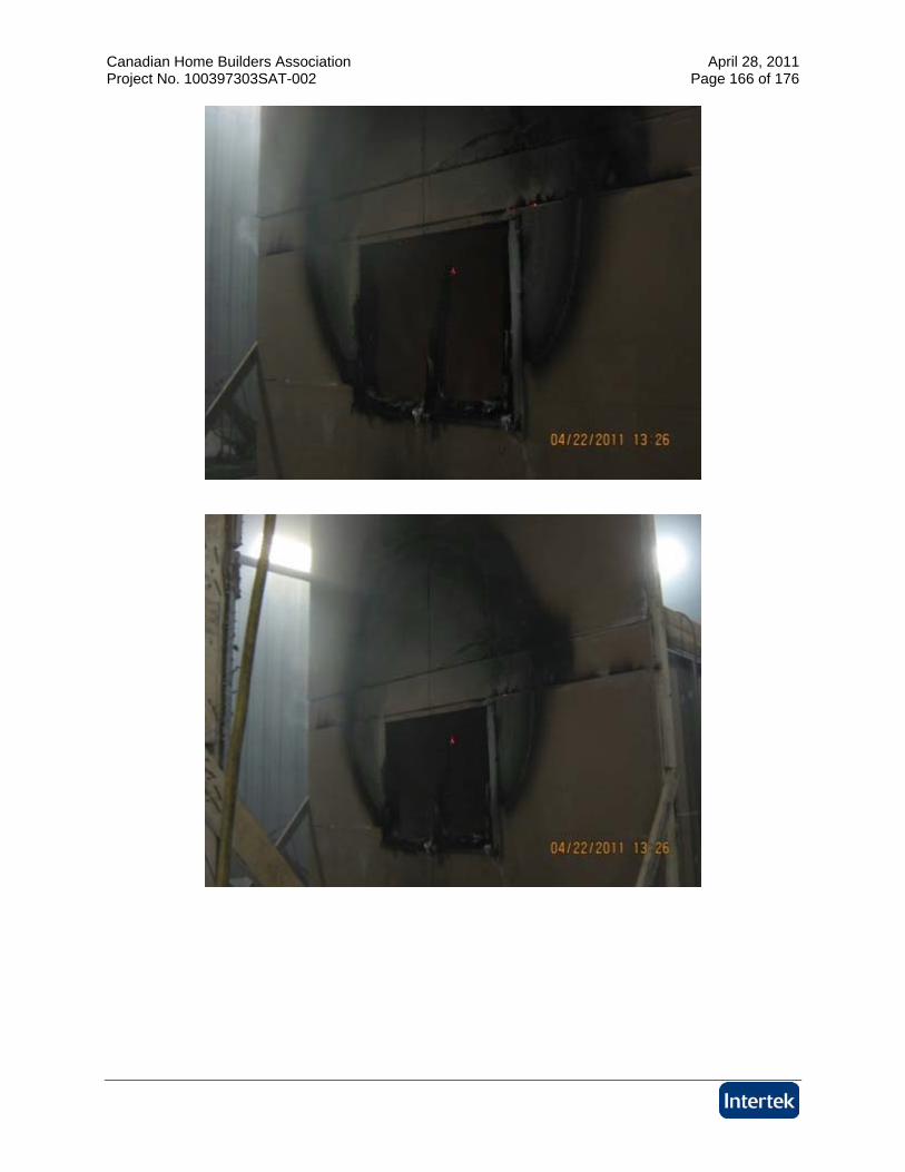
10:00 Exposing window glass broke 10:38 Glass broke open and flames 12:20 Flames 5’ above exposing window 13:00 Window fully breached 15:00 Drywall on exposing wall flaming at joints aboveexposing window 19:00 Flames from window increasing 20:00 Test terminated

Canadian Home Builders Association April 28, 2011 Project No. 100397303SAT-002 Page 7 of 176
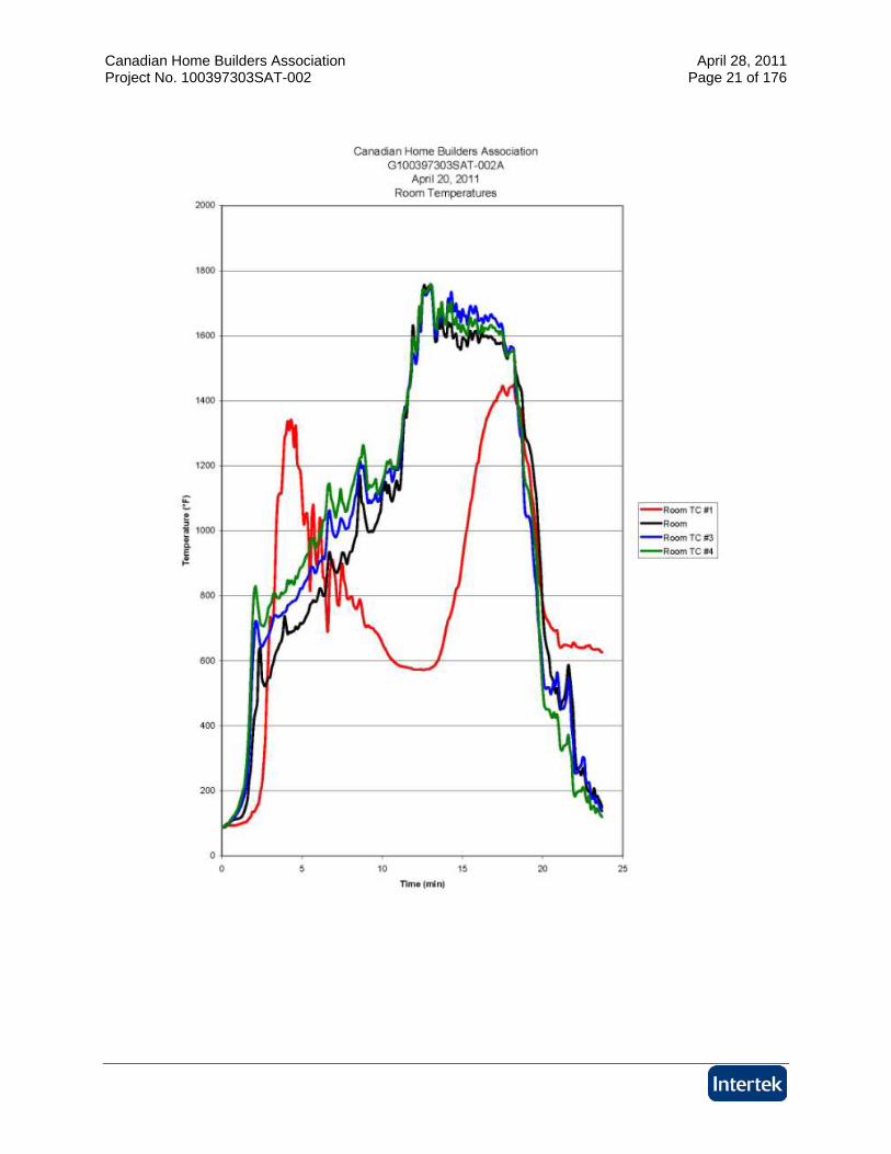
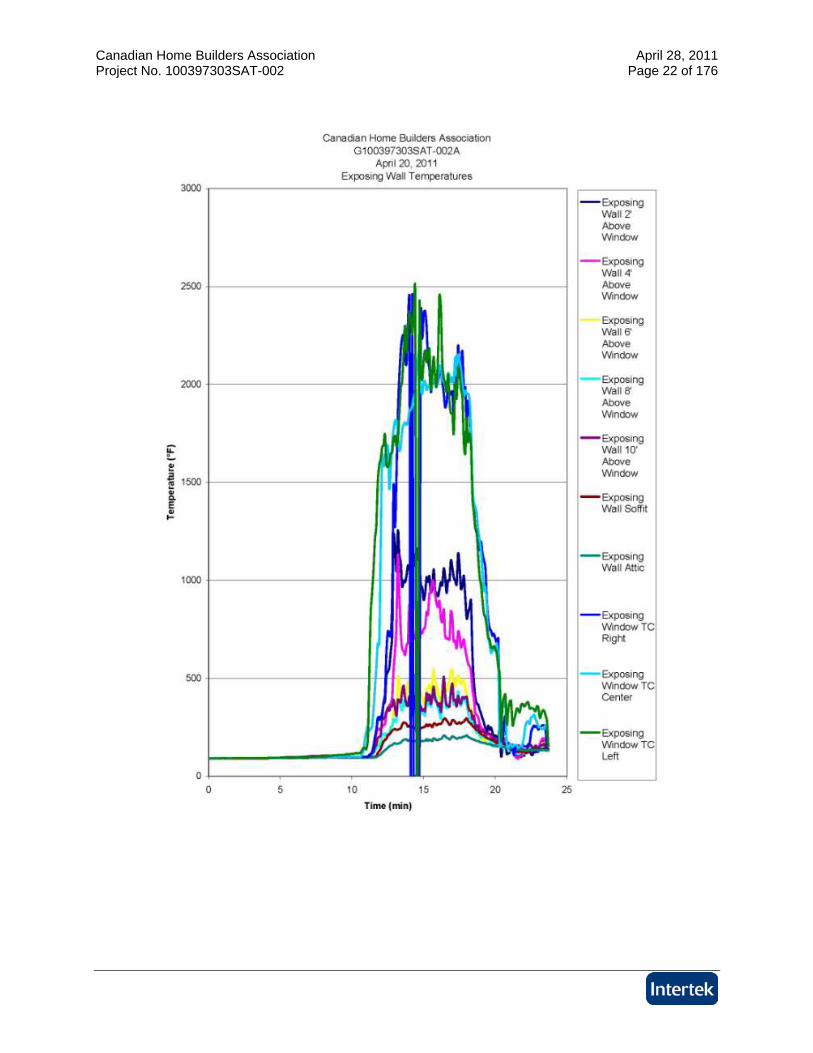
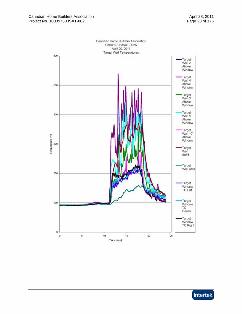
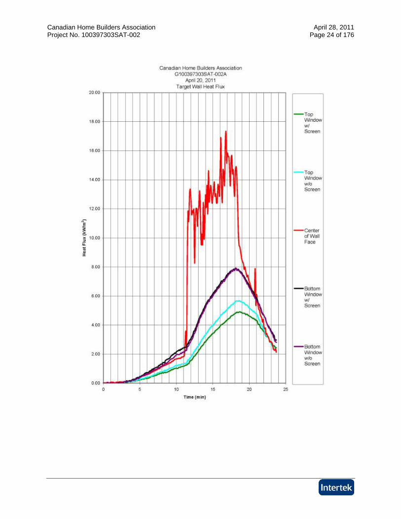
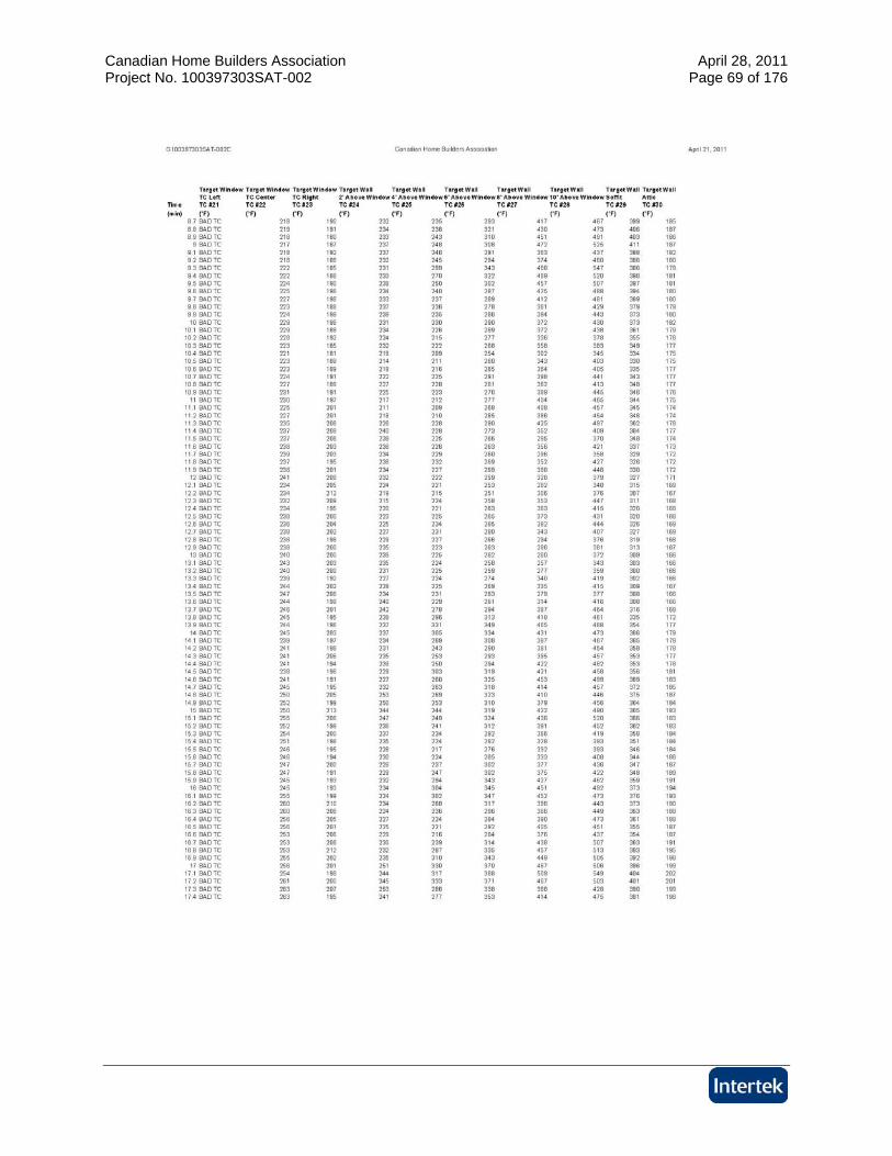
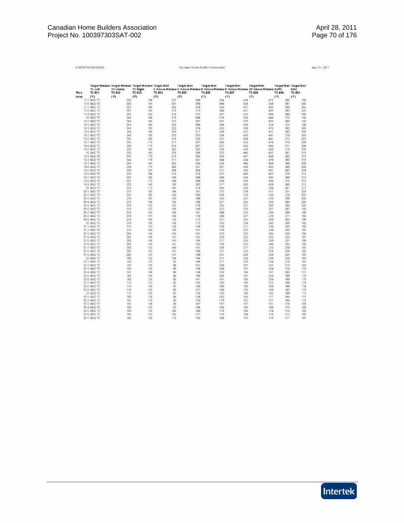
6 Conclusion Intertek Testing Services NA (Intertek) has conducted testing for Canadian Home Builders Association, on exterior wall construction with wood framed windows, to evaluate the heat flux exposure through windows from a neighboring building. Testing was conducted in accordance with the client supplied test procedure adapted from NRC-CNRC Full-Scale Fire Study of Spatial Separation, Research Report: IRC-RR-195, Dated May 19, 2005. This evaluation began April 20, 2011 and was completed April 22, 2011. Testing was conducted for research purposes only, and performed as described in Section 5 of this test report. Heat fluxes behind target windows did not exceed 12 kW/m2. Test data can be found in Appendices D, E, F and G. INTERTEK TESTING SERVICES NA, INC Reported by: _____________________ Joshua A. Vestal Project Engineer, Fire Resistance Reviewed by: _____________________ Victor M. Burgos Test Engineer, Fire Resistance

Canadian Home Builders Association April 28, 2011 Project No. 100397303SAT-002 Page 8 of 176
APPENDIX A Test Assembly Descriptions
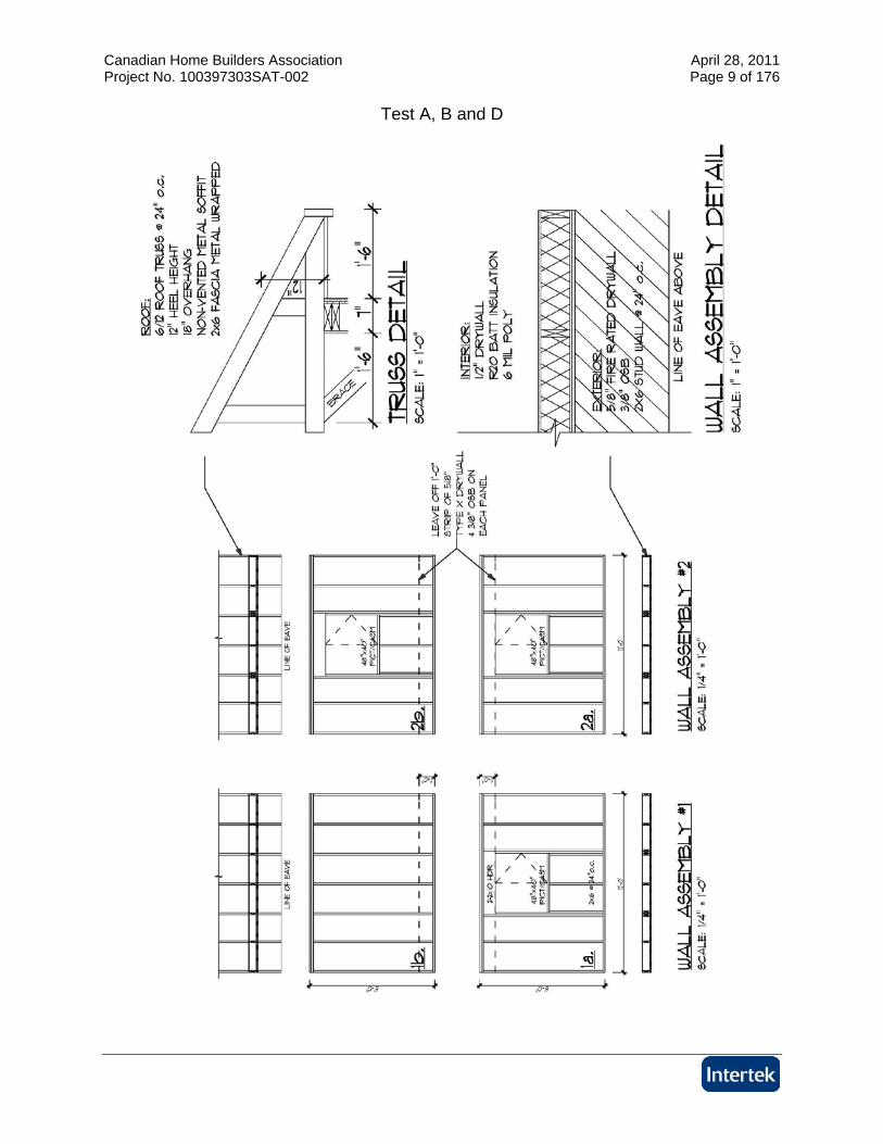
Canadian Home Builders Association April 28, 2011 Project No. 100397303SAT-002 Page 9 of 176
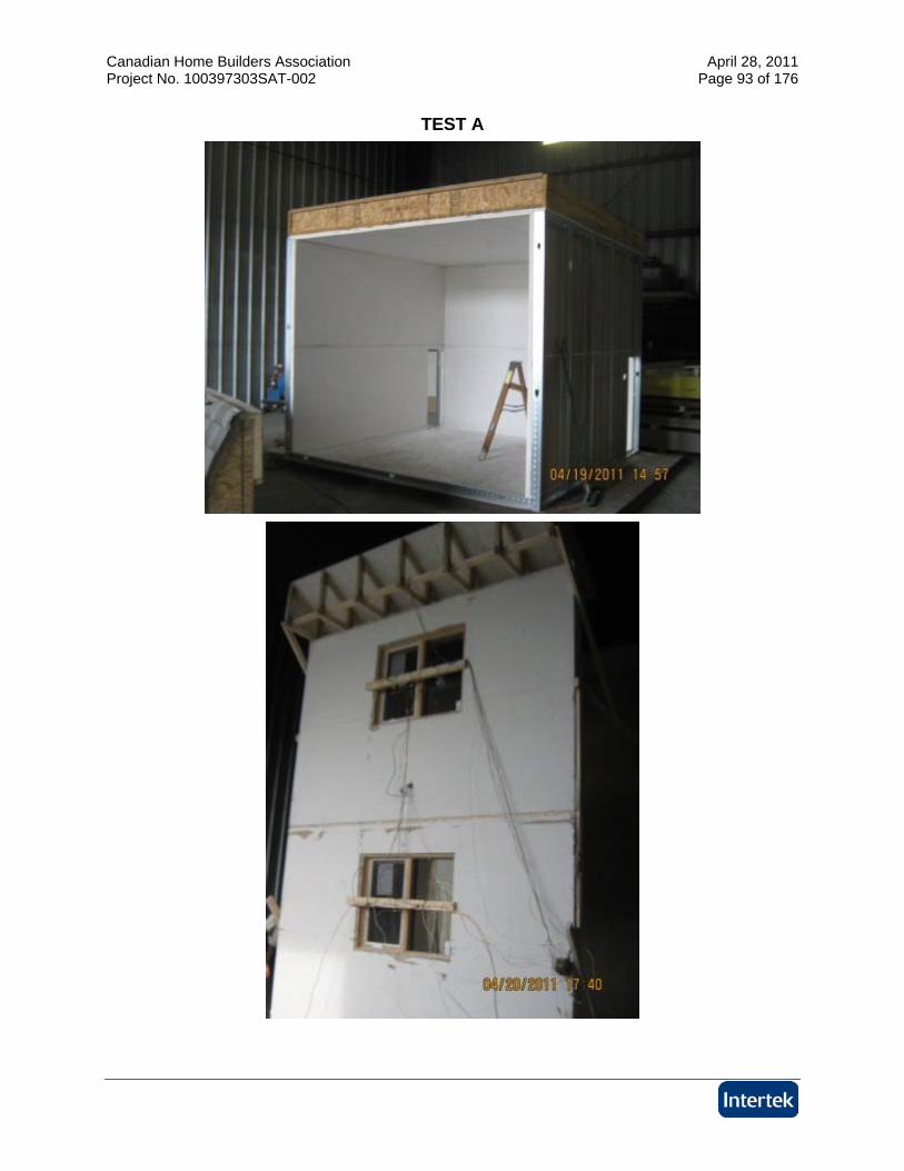
Test A, B and D
Canadian Home Builders Association April 28, 2011 Project No. 100397303SAT-002 Page 10 of 176
Canadian Home Builders Association April 28, 2011 Project No. 100397303SAT-002 Page 11 of 176

Canadian Home Builders Association April 28, 2011 Project No. 100397303SAT-002 Page 12 of 176

Canadian Home Builders Association April 28, 2011 Project No. 100397303SAT-002 Page 13 of 176

Canadian Home Builders Association April 28, 2011 Project No. 100397303SAT-002 Page 14 of 176
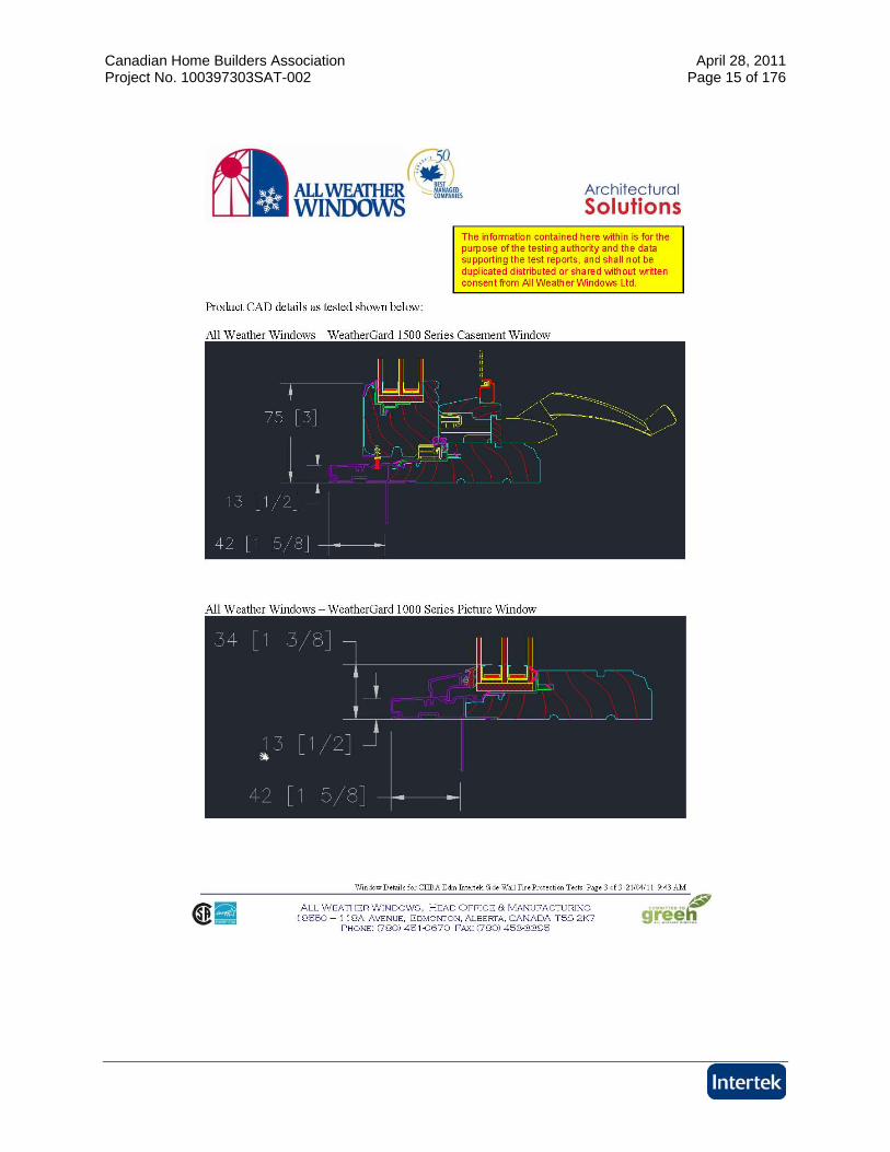
Canadian Home Builders Association April 28, 2011 Project No. 100397303SAT-002 Page 15 of 176

Canadian Home Builders Association April 28, 2011 Project No. 100397303SAT-002 Page 16 of 176
APPENDIX B Fire Compartment Room Description
Canadian Home Builders Association April 28, 2011 Project No. 100397303SAT-002 Page 17 of 176

Canadian Home Builders Association April 28, 2011 Project No. 100397303SAT-002 Page 18 of 176
APPENDIX C Wall Instrumentation
Canadian Home Builders Association April 28, 2011 Project No. 100397303SAT-002 Page 19 of 176

Canadian Home Builders Association April 28, 2011 Project No. 100397303SAT-002 Page 20 of 176
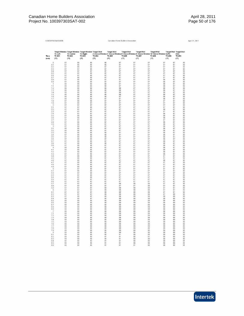
APPENDIX D Test A Data
Canadian Home Builders Association April 28, 2011 Project No. 100397303SAT-002 Page 21 of 176
Canadian Home Builders Association April 28, 2011 Project No. 100397303SAT-002 Page 22 of 176
Canadian Home Builders Association April 28, 2011 Project No. 100397303SAT-002 Page 23 of 176
Canadian Home Builders Association April 28, 2011 Project No. 100397303SAT-002 Page 24 of 176
Canadian Home Builders Association April 28, 2011 Project No. 100397303SAT-002 Page 25 of 176

Canadian Home Builders Association April 28, 2011 Project No. 100397303SAT-002 Page 26 of 176

Canadian Home Builders Association April 28, 2011 Project No. 100397303SAT-002 Page 27 of 176
Canadian Home Builders Association April 28, 2011 Project No. 100397303SAT-002 Page 28 of 176
Canadian Home Builders Association April 28, 2011 Project No. 100397303SAT-002 Page 29 of 176

Canadian Home Builders Association April 28, 2011 Project No. 100397303SAT-002 Page 30 of 176

Canadian Home Builders Association April 28, 2011 Project No. 100397303SAT-002 Page 31 of 176

Canadian Home Builders Association April 28, 2011 Project No. 100397303SAT-002 Page 32 of 176

Canadian Home Builders Association April 28, 2011 Project No. 100397303SAT-002 Page 33 of 176

Canadian Home Builders Association April 28, 2011 Project No. 100397303SAT-002 Page 34 of 176

Canadian Home Builders Association April 28, 2011 Project No. 100397303SAT-002 Page 35 of 176

Canadian Home Builders Association April 28, 2011 Project No. 100397303SAT-002 Page 36 of 176
Canadian Home Builders Association April 28, 2011 Project No. 100397303SAT-002 Page 37 of 176

Canadian Home Builders Association April 28, 2011 Project No. 100397303SAT-002 Page 38 of 176
APPENDIX E Test B Data
Canadian Home Builders Association April 28, 2011 Project No. 100397303SAT-002 Page 39 of 176
Canadian Home Builders Association April 28, 2011 Project No. 100397303SAT-002 Page 40 of 176
Canadian Home Builders Association April 28, 2011 Project No. 100397303SAT-002 Page 41 of 176
Canadian Home Builders Association April 28, 2011 Project No. 100397303SAT-002 Page 42 of 176
Canadian Home Builders Association April 28, 2011 Project No. 100397303SAT-002 Page 43 of 176
Canadian Home Builders Association April 28, 2011 Project No. 100397303SAT-002 Page 44 of 176

Canadian Home Builders Association April 28, 2011 Project No. 100397303SAT-002 Page 45 of 176

Canadian Home Builders Association April 28, 2011 Project No. 100397303SAT-002 Page 46 of 176

Canadian Home Builders Association April 28, 2011 Project No. 100397303SAT-002 Page 47 of 176
Canadian Home Builders Association April 28, 2011 Project No. 100397303SAT-002 Page 48 of 176

Canadian Home Builders Association April 28, 2011 Project No. 100397303SAT-002 Page 49 of 176
Canadian Home Builders Association April 28, 2011 Project No. 100397303SAT-002 Page 50 of 176

Canadian Home Builders Association April 28, 2011 Project No. 100397303SAT-002 Page 51 of 176

Canadian Home Builders Association April 28, 2011 Project No. 100397303SAT-002 Page 52 of 176
Canadian Home Builders Association April 28, 2011 Project No. 100397303SAT-002 Page 53 of 176

Canadian Home Builders Association April 28, 2011 Project No. 100397303SAT-002 Page 54 of 176

Canadian Home Builders Association April 28, 2011 Project No. 100397303SAT-002 Page 55 of 176

Canadian Home Builders Association April 28, 2011 Project No. 100397303SAT-002 Page 56 of 176
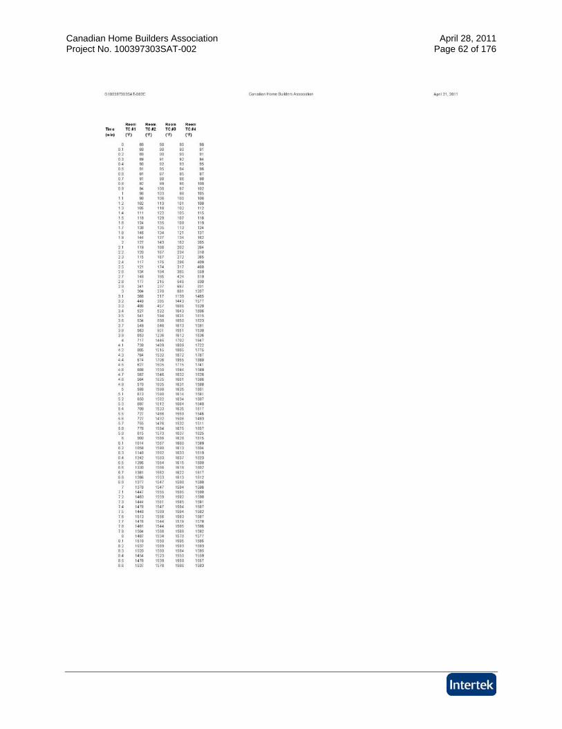
APPENDIX F Test C Data
Canadian Home Builders Association April 28, 2011 Project No. 100397303SAT-002 Page 57 of 176
Canadian Home Builders Association April 28, 2011 Project No. 100397303SAT-002 Page 58 of 176
Canadian Home Builders Association April 28, 2011 Project No. 100397303SAT-002 Page 59 of 176
Canadian Home Builders Association April 28, 2011 Project No. 100397303SAT-002 Page 60 of 176
Canadian Home Builders Association April 28, 2011 Project No. 100397303SAT-002 Page 61 of 176
Canadian Home Builders Association April 28, 2011 Project No. 100397303SAT-002 Page 62 of 176

Canadian Home Builders Association April 28, 2011 Project No. 100397303SAT-002 Page 63 of 176

Canadian Home Builders Association April 28, 2011 Project No. 100397303SAT-002 Page 64 of 176
Canadian Home Builders Association April 28, 2011 Project No. 100397303SAT-002 Page 65 of 176
Canadian Home Builders Association April 28, 2011 Project No. 100397303SAT-002 Page 66 of 176
Canadian Home Builders Association April 28, 2011 Project No. 100397303SAT-002 Page 67 of 176
Canadian Home Builders Association April 28, 2011 Project No. 100397303SAT-002 Page 68 of 176
Canadian Home Builders Association April 28, 2011 Project No. 100397303SAT-002 Page 69 of 176
Canadian Home Builders Association April 28, 2011 Project No. 100397303SAT-002 Page 70 of 176
Canadian Home Builders Association April 28, 2011 Project No. 100397303SAT-002 Page 71 of 176
Canadian Home Builders Association April 28, 2011 Project No. 100397303SAT-002 Page 72 of 176
Canadian Home Builders Association April 28, 2011 Project No. 100397303SAT-002 Page 73 of 176

Canadian Home Builders Association April 28, 2011 Project No. 100397303SAT-002 Page 74 of 176
APPENDIX G Test D Data
Canadian Home Builders Association April 28, 2011 Project No. 100397303SAT-002 Page 75 of 176
Canadian Home Builders Association April 28, 2011 Project No. 100397303SAT-002 Page 76 of 176
Canadian Home Builders Association April 28, 2011 Project No. 100397303SAT-002 Page 77 of 176
Canadian Home Builders Association April 28, 2011 Project No. 100397303SAT-002 Page 78 of 176
Canadian Home Builders Association April 28, 2011 Project No. 100397303SAT-002 Page 79 of 176

Canadian Home Builders Association April 28, 2011 Project No. 100397303SAT-002 Page 80 of 176

Canadian Home Builders Association April 28, 2011 Project No. 100397303SAT-002 Page 81 of 176

Canadian Home Builders Association April 28, 2011 Project No. 100397303SAT-002 Page 82 of 176
Canadian Home Builders Association April 28, 2011 Project No. 100397303SAT-002 Page 83 of 176
Canadian Home Builders Association April 28, 2011 Project No. 100397303SAT-002 Page 84 of 176

Canadian Home Builders Association April 28, 2011 Project No. 100397303SAT-002 Page 85 of 176

Canadian Home Builders Association April 28, 2011 Project No. 100397303SAT-002 Page 86 of 176
Canadian Home Builders Association April 28, 2011 Project No. 100397303SAT-002 Page 87 of 176
Canadian Home Builders Association April 28, 2011 Project No. 100397303SAT-002 Page 88 of 176

Canadian Home Builders Association April 28, 2011 Project No. 100397303SAT-002 Page 89 of 176
Canadian Home Builders Association April 28, 2011 Project No. 100397303SAT-002 Page 90 of 176

Canadian Home Builders Association April 28, 2011 Project No. 100397303SAT-002 Page 91 of 176

Canadian Home Builders Association April 28, 2011 Project No. 100397303SAT-002 Page 92 of 176
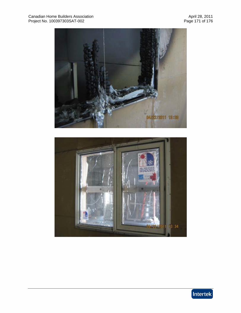
APPENDIX H Photographs
Canadian Home Builders Association April 28, 2011 Project No. 100397303SAT-002 Page 93 of 176
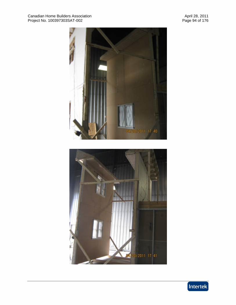
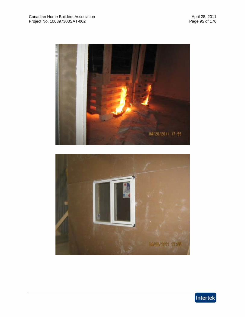
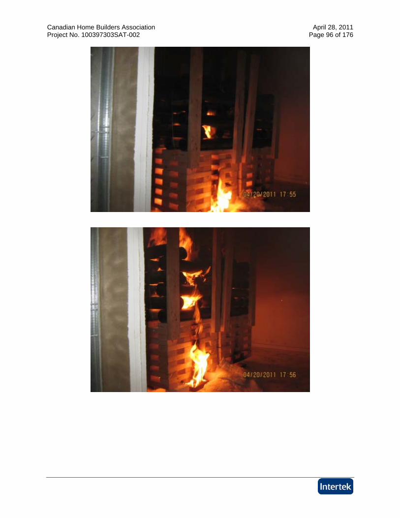
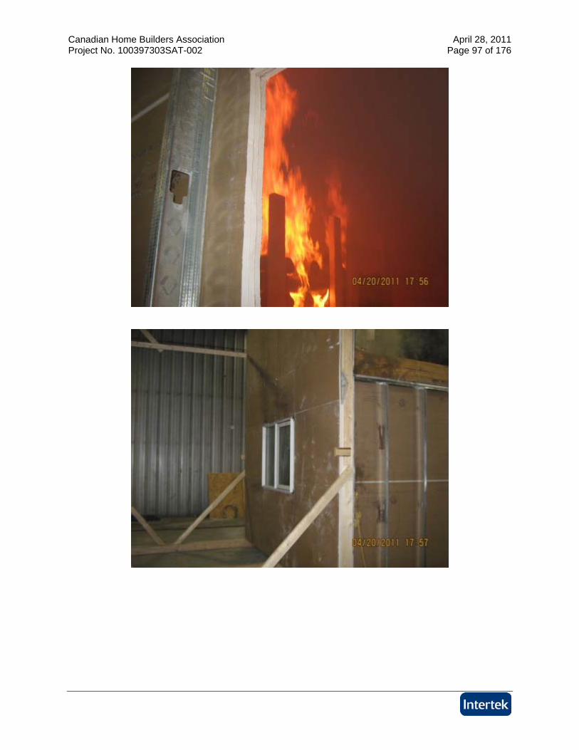
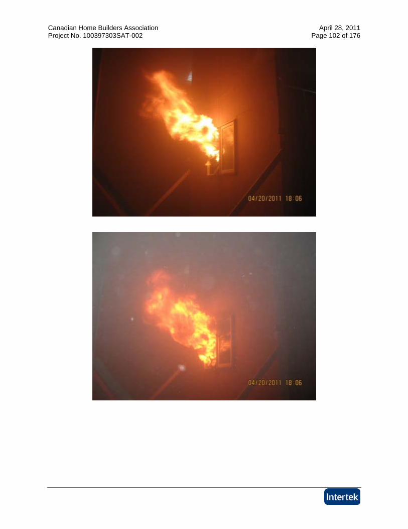
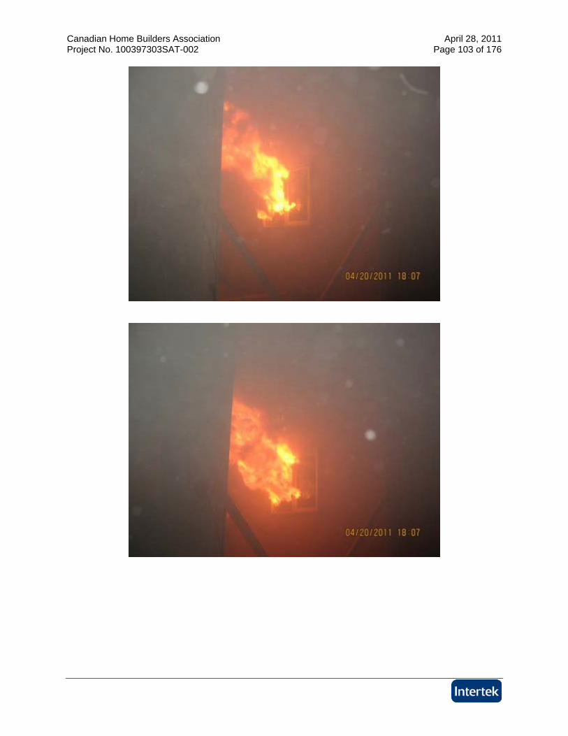
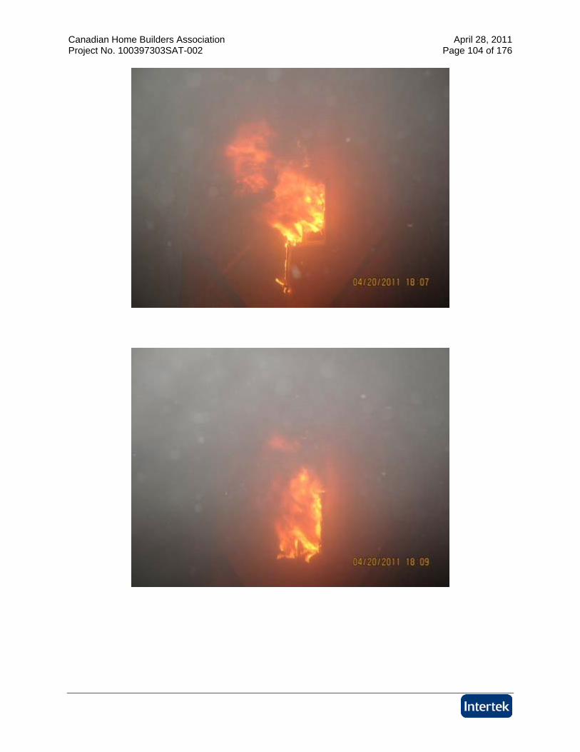
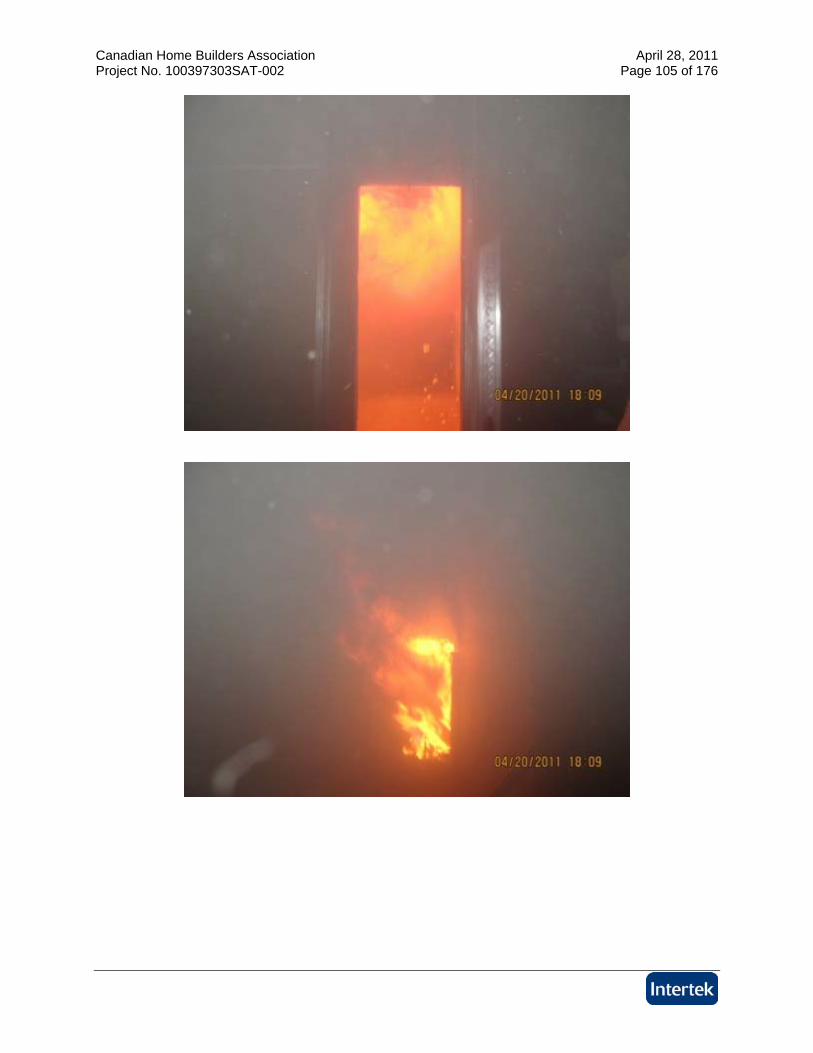
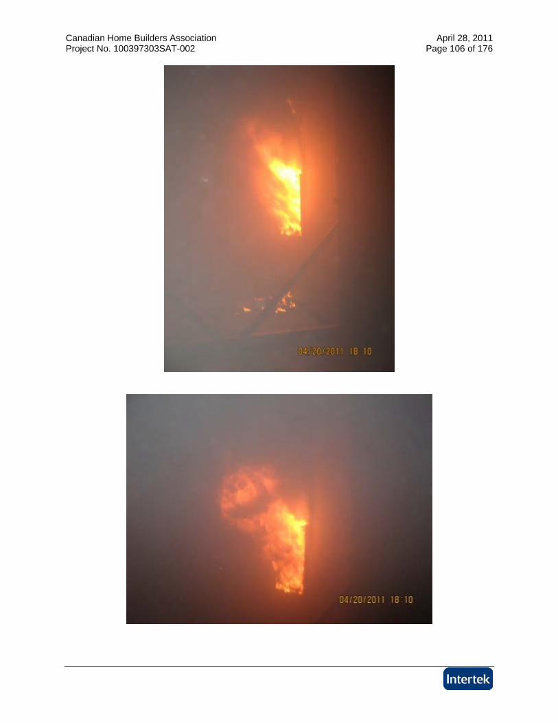
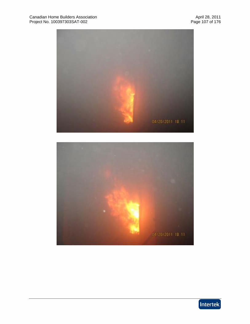
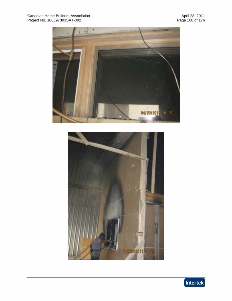
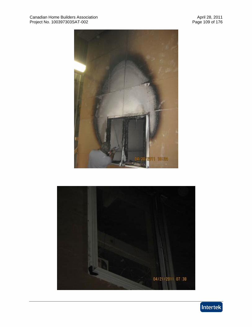
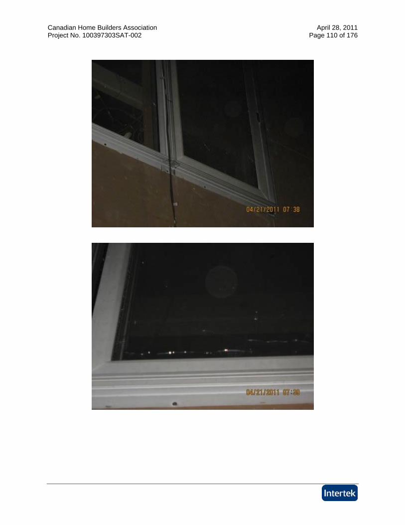
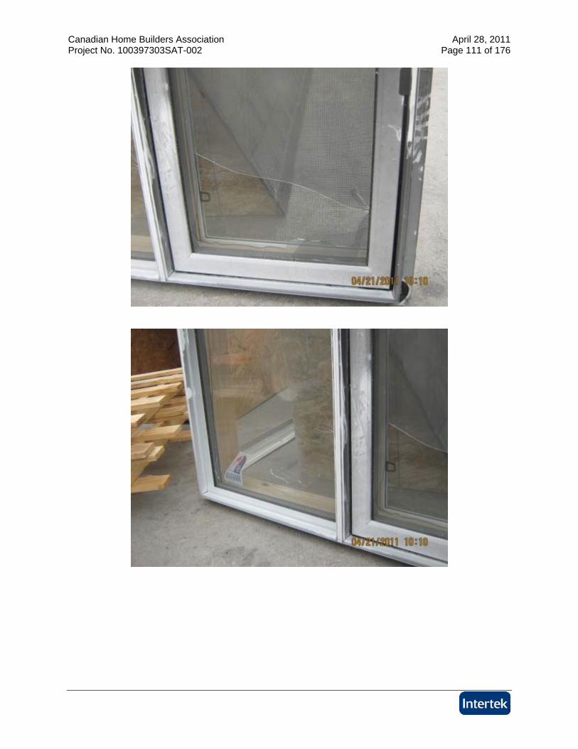
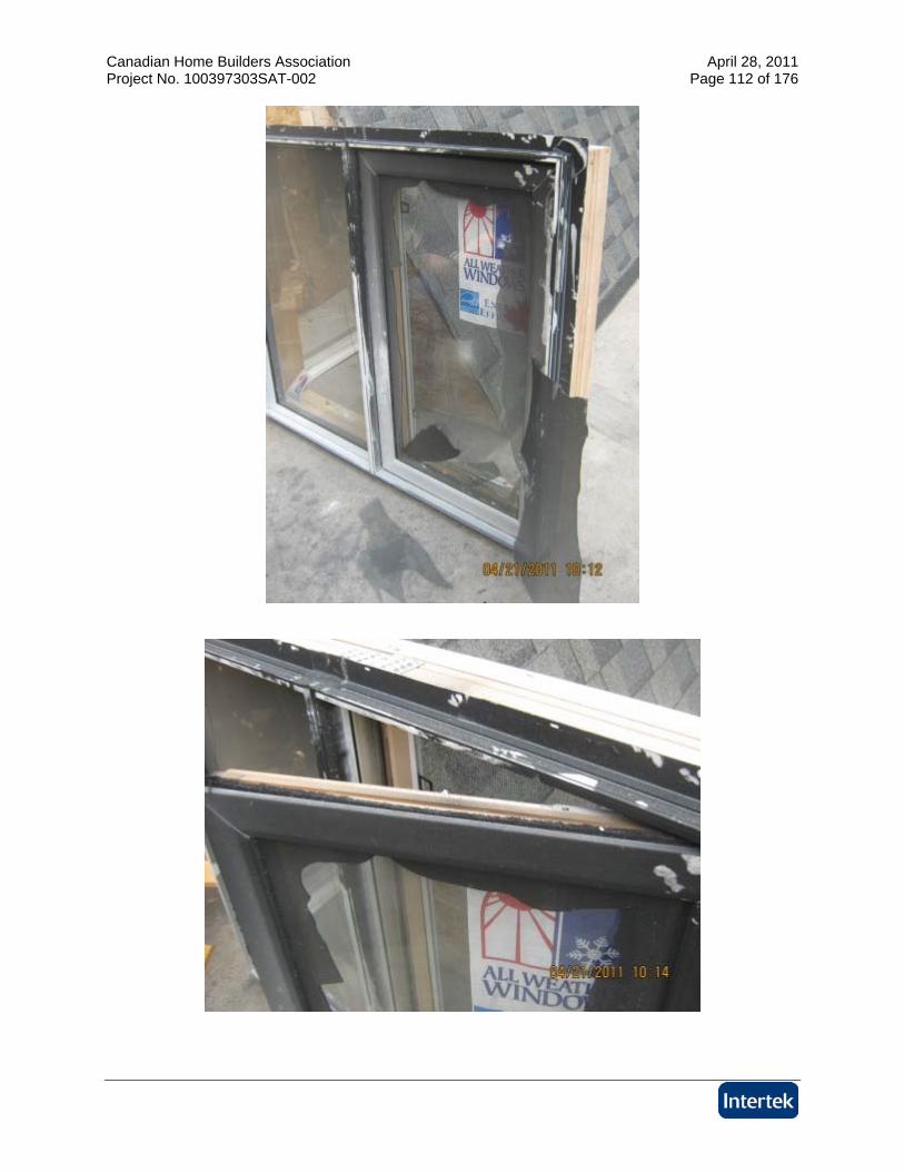
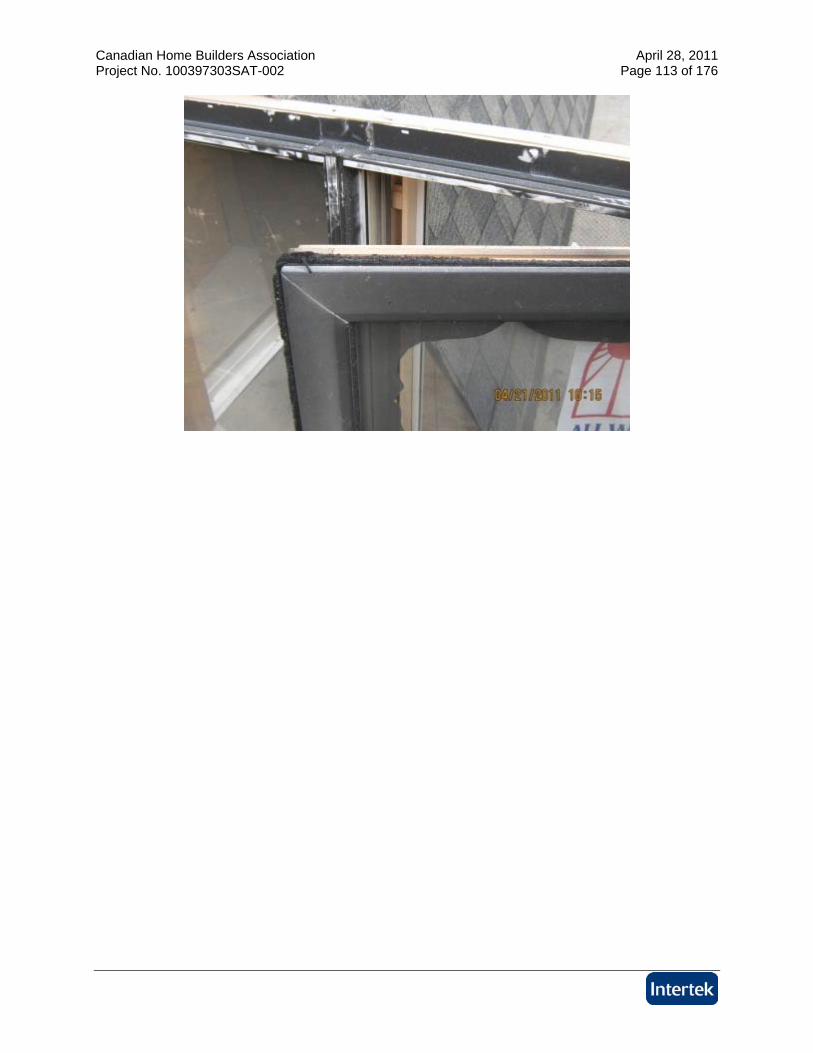
TEST A
Canadian Home Builders Association April 28, 2011 Project No. 100397303SAT-002 Page 94 of 176
Canadian Home Builders Association April 28, 2011 Project No. 100397303SAT-002 Page 95 of 176
Canadian Home Builders Association April 28, 2011 Project No. 100397303SAT-002 Page 96 of 176
Canadian Home Builders Association April 28, 2011 Project No. 100397303SAT-002 Page 97 of 176
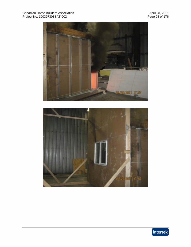
Canadian Home Builders Association April 28, 2011 Project No. 100397303SAT-002 Page 98 of 176
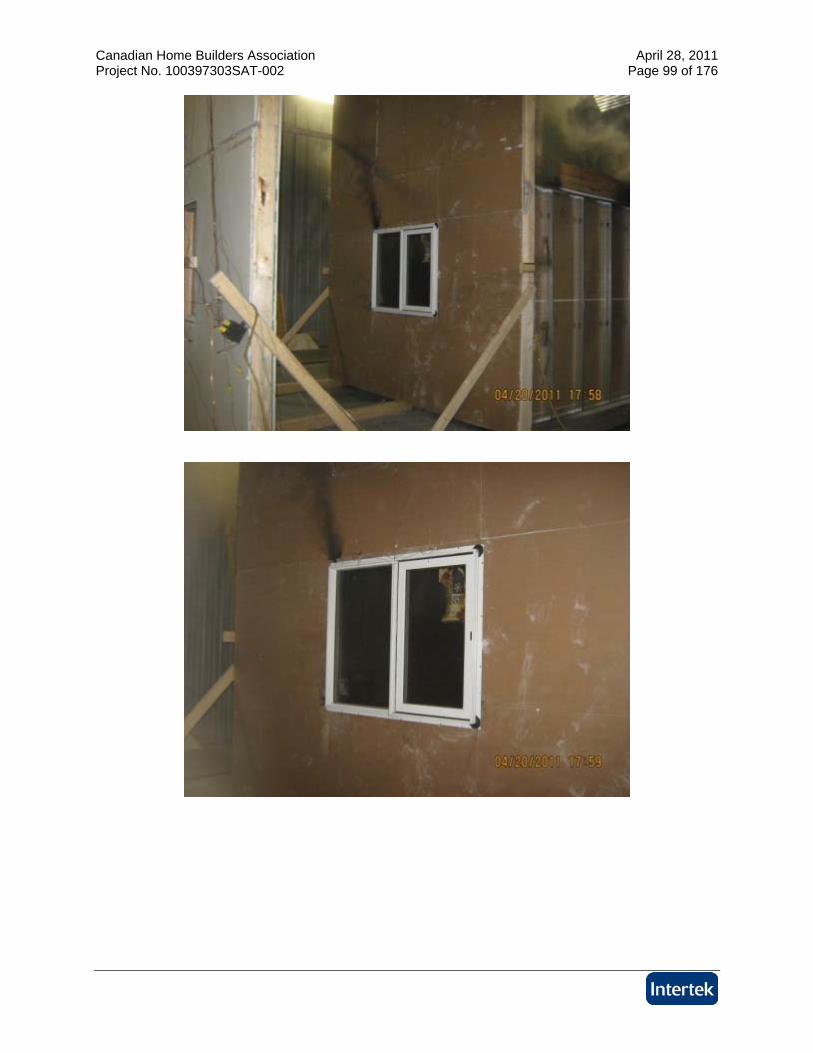
Canadian Home Builders Association April 28, 2011 Project No. 100397303SAT-002 Page 99 of 176
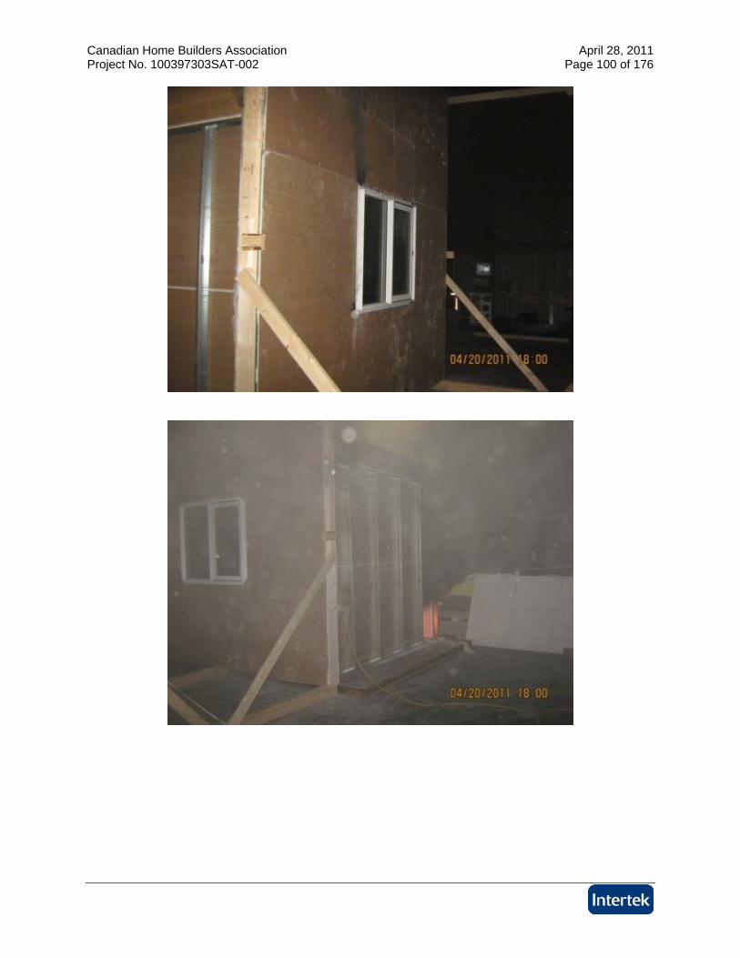
Canadian Home Builders Association April 28, 2011 Project No. 100397303SAT-002 Page 100 of 176
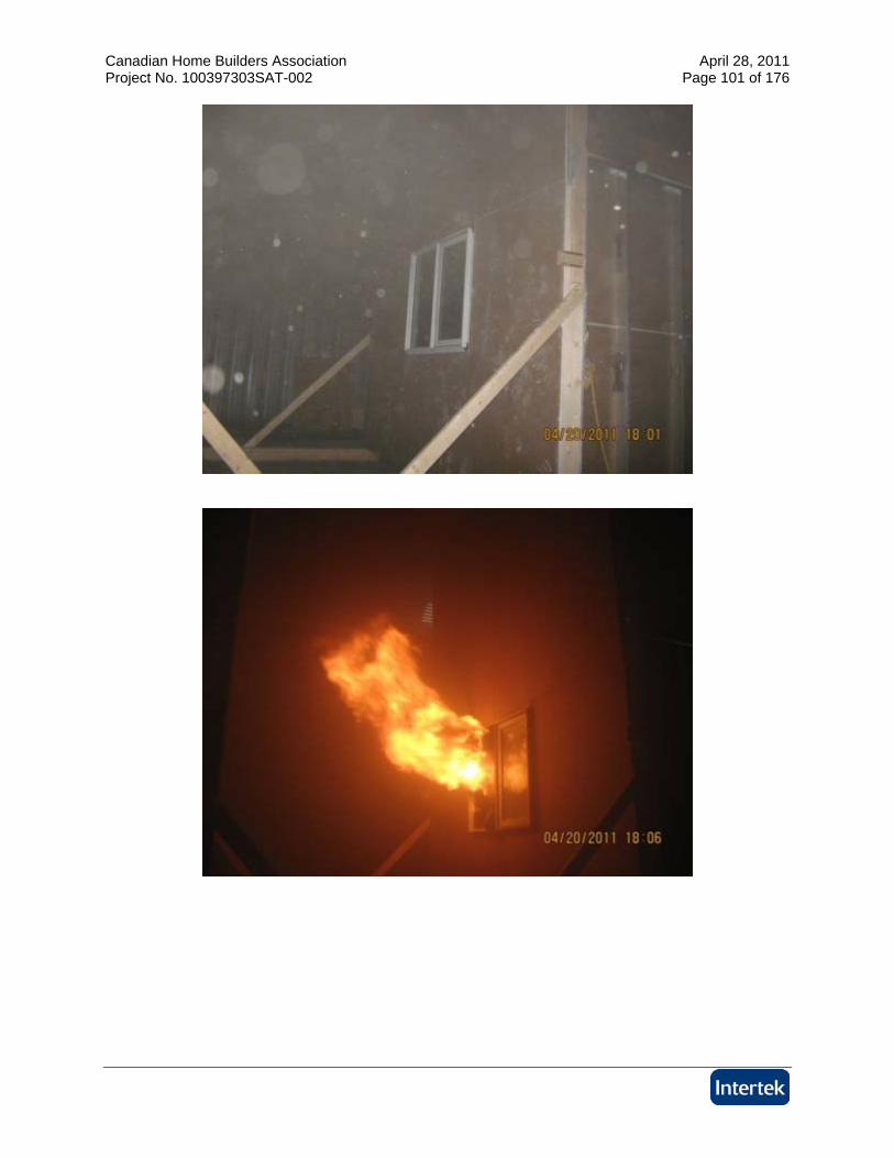
Canadian Home Builders Association April 28, 2011 Project No. 100397303SAT-002 Page 101 of 176
Canadian Home Builders Association April 28, 2011 Project No. 100397303SAT-002 Page 102 of 176
Canadian Home Builders Association April 28, 2011 Project No. 100397303SAT-002 Page 103 of 176
Canadian Home Builders Association April 28, 2011 Project No. 100397303SAT-002 Page 104 of 176
Canadian Home Builders Association April 28, 2011 Project No. 100397303SAT-002 Page 105 of 176
Canadian Home Builders Association April 28, 2011 Project No. 100397303SAT-002 Page 106 of 176
Canadian Home Builders Association April 28, 2011 Project No. 100397303SAT-002 Page 107 of 176
Canadian Home Builders Association April 28, 2011 Project No. 100397303SAT-002 Page 108 of 176
Canadian Home Builders Association April 28, 2011 Project No. 100397303SAT-002 Page 109 of 176
Canadian Home Builders Association April 28, 2011 Project No. 100397303SAT-002 Page 110 of 176
Canadian Home Builders Association April 28, 2011 Project No. 100397303SAT-002 Page 111 of 176
Canadian Home Builders Association April 28, 2011 Project No. 100397303SAT-002 Page 112 of 176
Canadian Home Builders Association April 28, 2011 Project No. 100397303SAT-002 Page 113 of 176
Canadian Home Builders Association April 28, 2011 Project No. 100397303SAT-002 Page 114 of 176
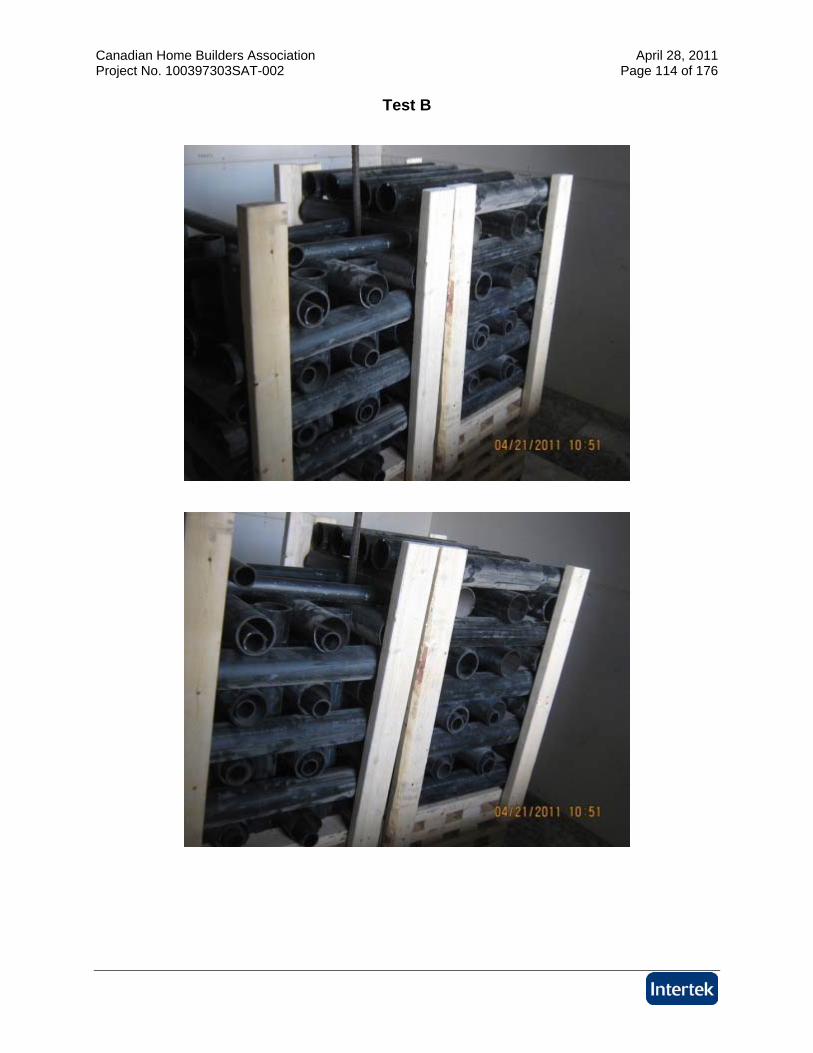
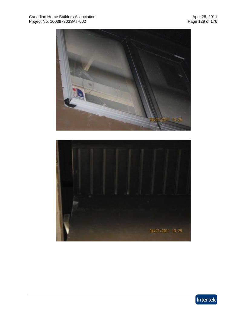
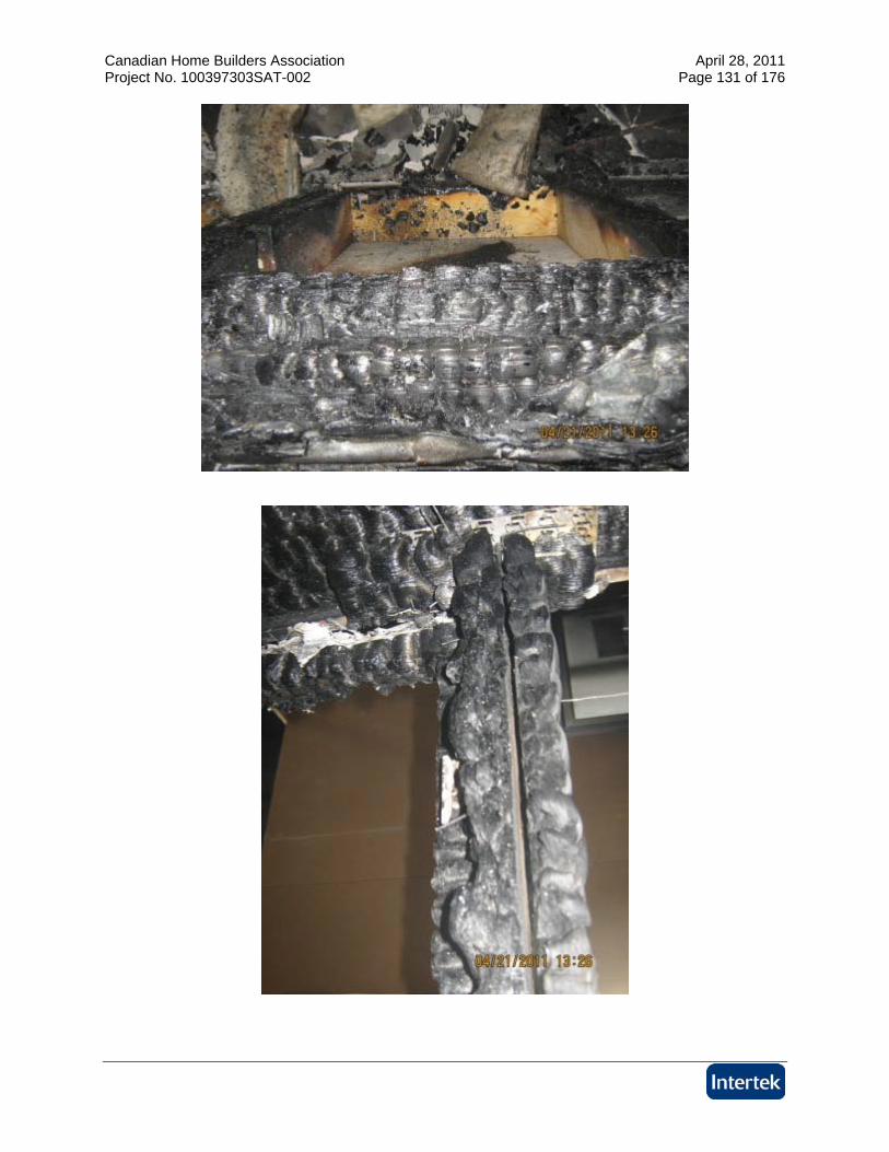
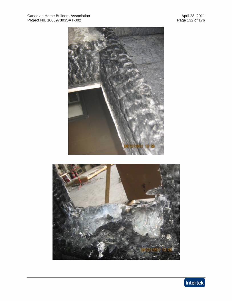
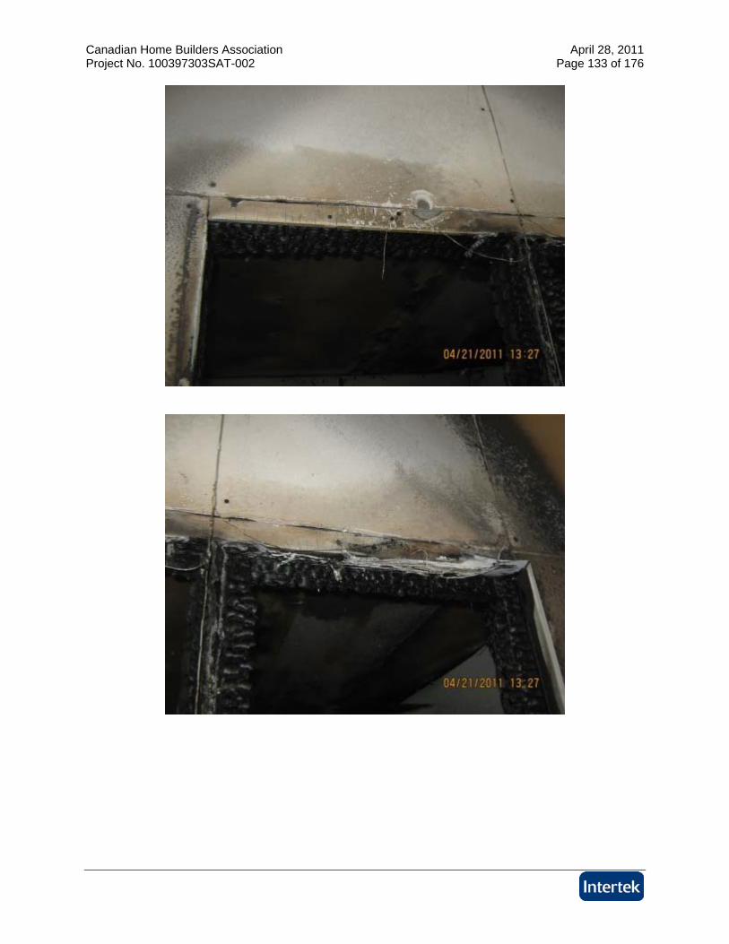
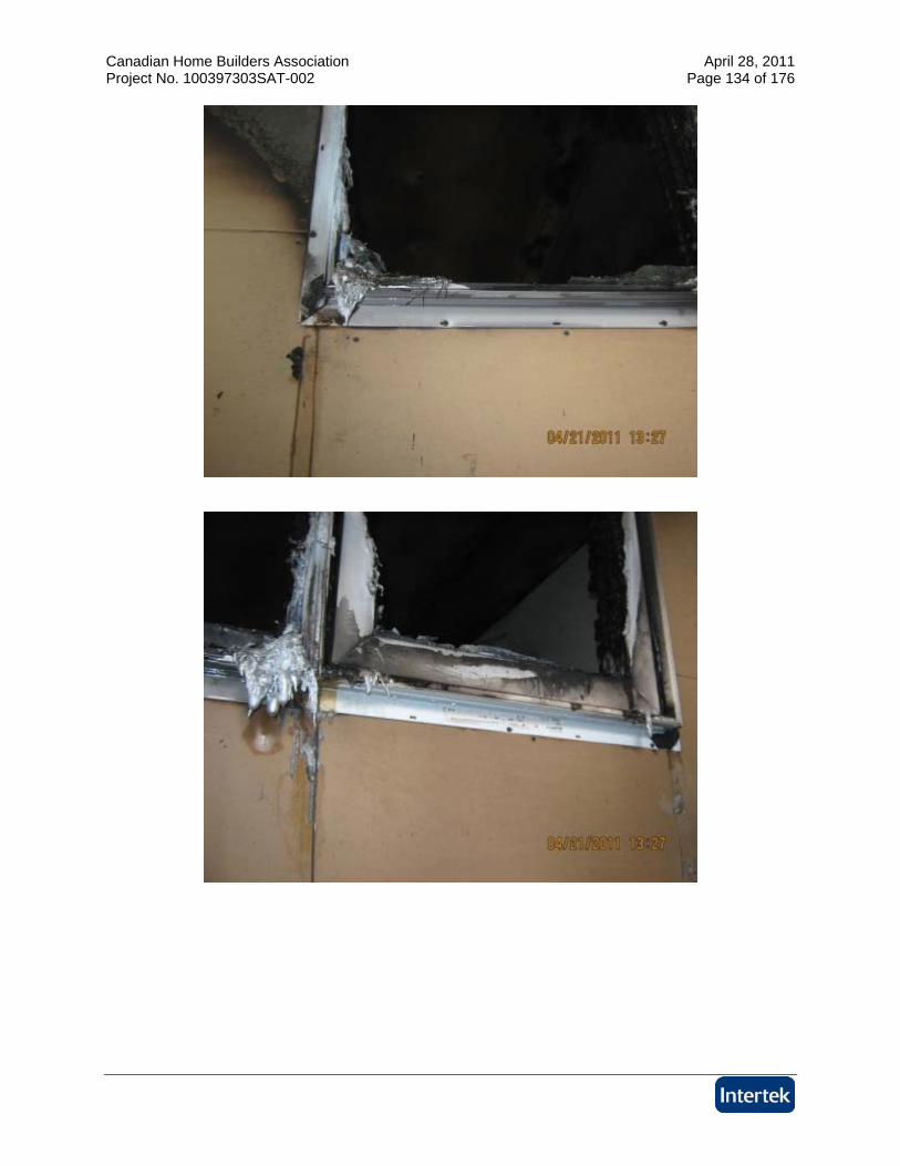
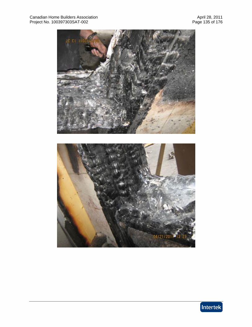
Test B
Canadian Home Builders Association April 28, 2011 Project No. 100397303SAT-002 Page 115 of 176
Canadian Home Builders Association April 28, 2011 Project No. 100397303SAT-002 Page 116 of 176
Canadian Home Builders Association April 28, 2011 Project No. 100397303SAT-002 Page 117 of 176
Canadian Home Builders Association April 28, 2011 Project No. 100397303SAT-002 Page 118 of 176
Canadian Home Builders Association April 28, 2011 Project No. 100397303SAT-002 Page 119 of 176
Canadian Home Builders Association April 28, 2011 Project No. 100397303SAT-002 Page 120 of 176
Canadian Home Builders Association April 28, 2011 Project No. 100397303SAT-002 Page 121 of 176
Canadian Home Builders Association April 28, 2011 Project No. 100397303SAT-002 Page 122 of 176
Canadian Home Builders Association April 28, 2011 Project No. 100397303SAT-002 Page 123 of 176

Canadian Home Builders Association April 28, 2011 Project No. 100397303SAT-002 Page 124 of 176
Canadian Home Builders Association April 28, 2011 Project No. 100397303SAT-002 Page 125 of 176
Canadian Home Builders Association April 28, 2011 Project No. 100397303SAT-002 Page 126 of 176
Canadian Home Builders Association April 28, 2011 Project No. 100397303SAT-002 Page 127 of 176
Canadian Home Builders Association April 28, 2011 Project No. 100397303SAT-002 Page 128 of 176
Canadian Home Builders Association April 28, 2011 Project No. 100397303SAT-002 Page 129 of 176
Canadian Home Builders Association April 28, 2011 Project No. 100397303SAT-002 Page 130 of 176
Canadian Home Builders Association April 28, 2011 Project No. 100397303SAT-002 Page 131 of 176
Canadian Home Builders Association April 28, 2011 Project No. 100397303SAT-002 Page 132 of 176
Canadian Home Builders Association April 28, 2011 Project No. 100397303SAT-002 Page 133 of 176
Canadian Home Builders Association April 28, 2011 Project No. 100397303SAT-002 Page 134 of 176
Canadian Home Builders Association April 28, 2011 Project No. 100397303SAT-002 Page 135 of 176
Canadian Home Builders Association April 28, 2011 Project No. 100397303SAT-002 Page 136 of 176
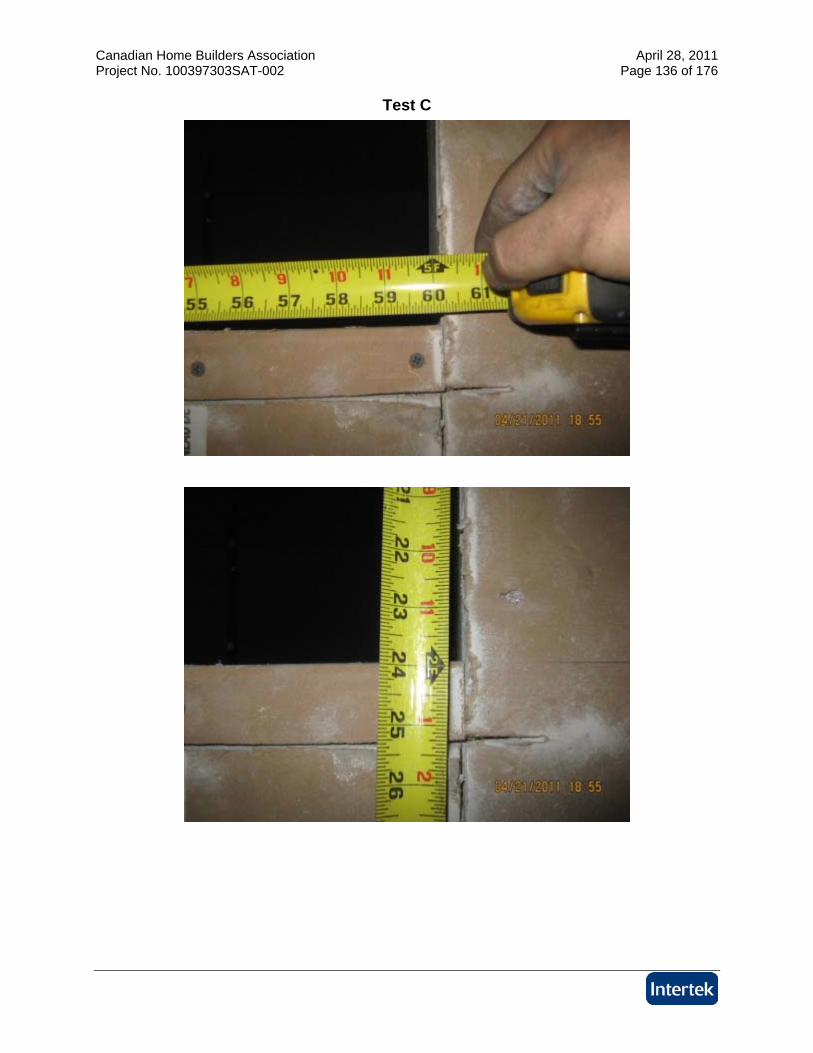
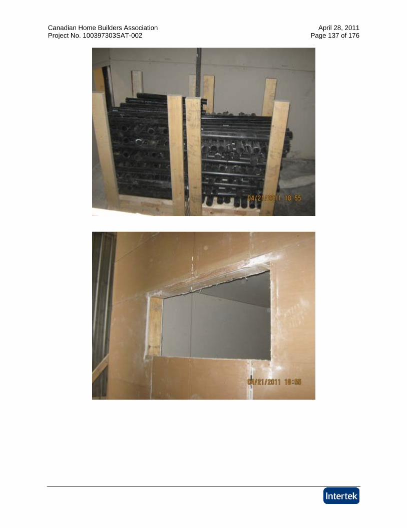
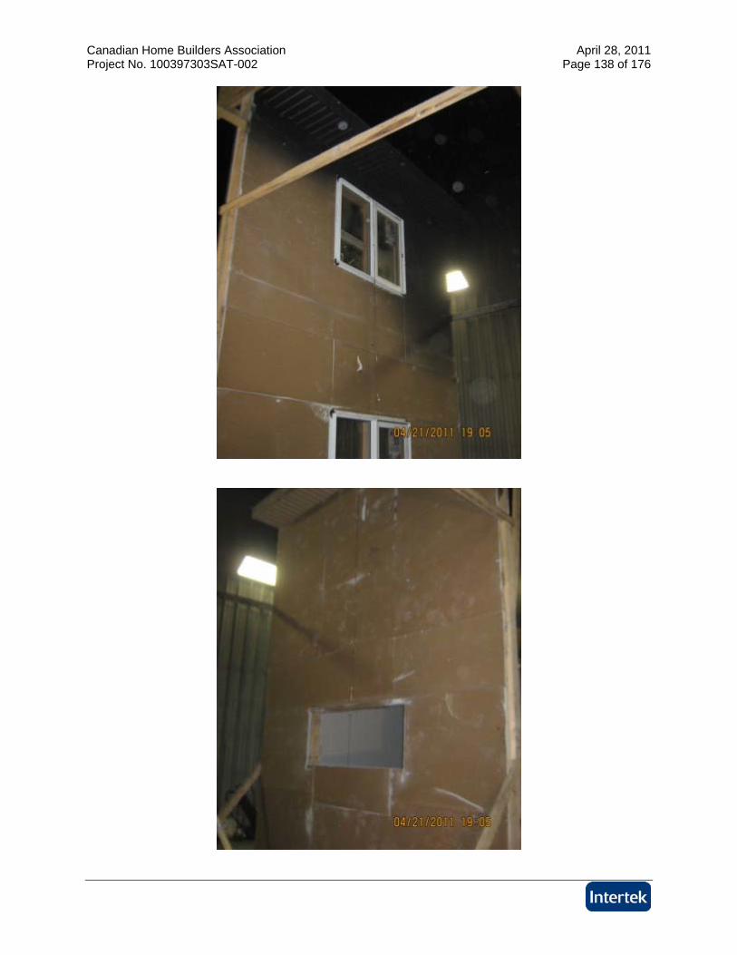
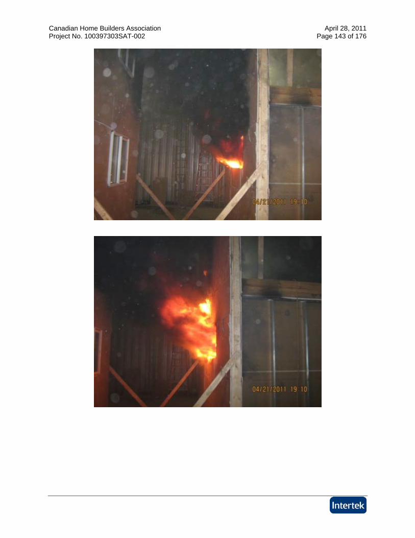
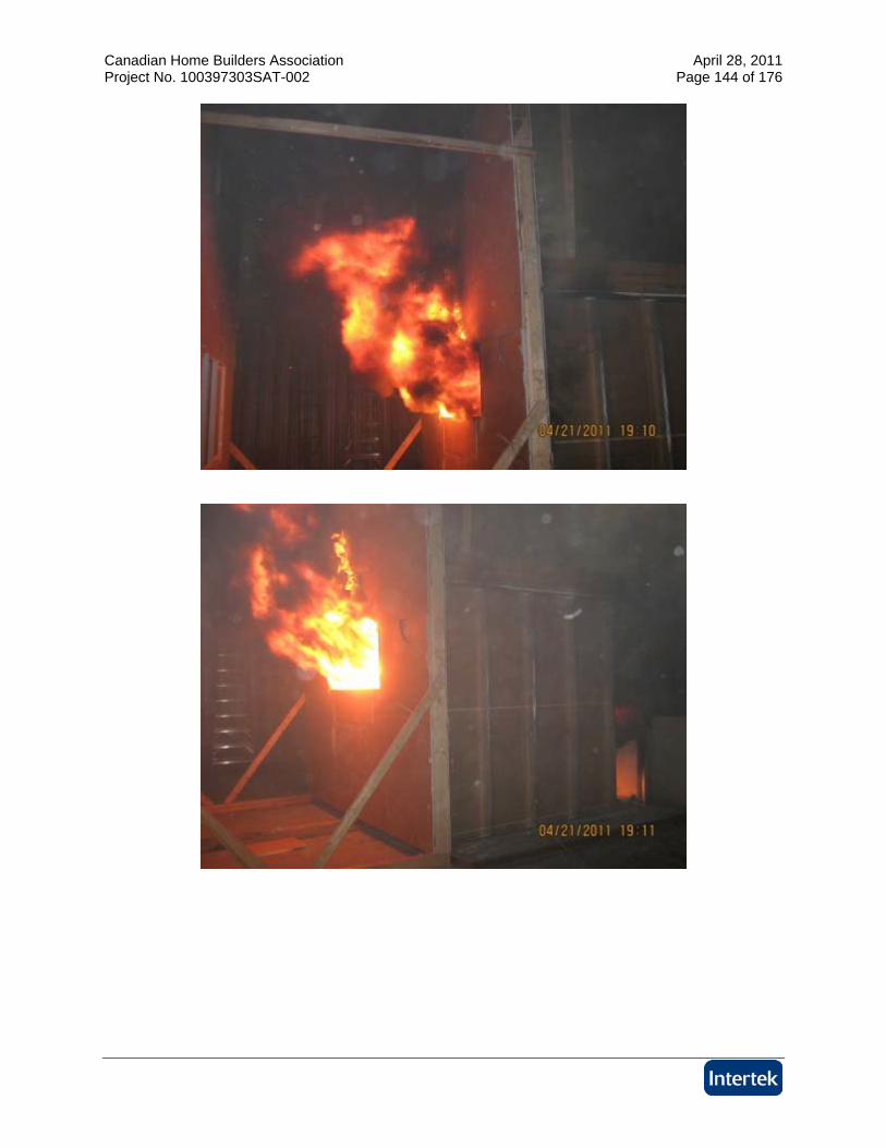
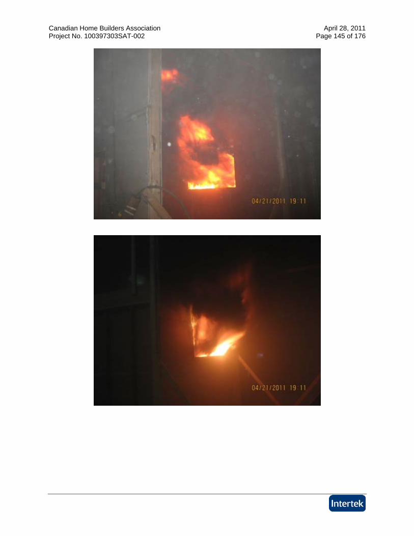
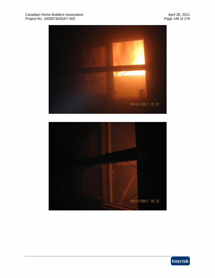
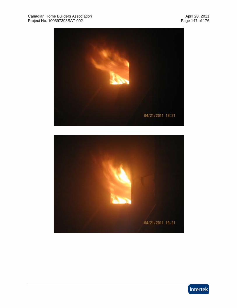
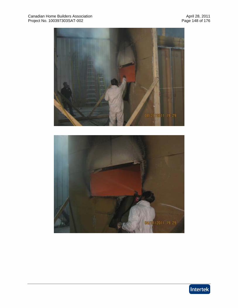
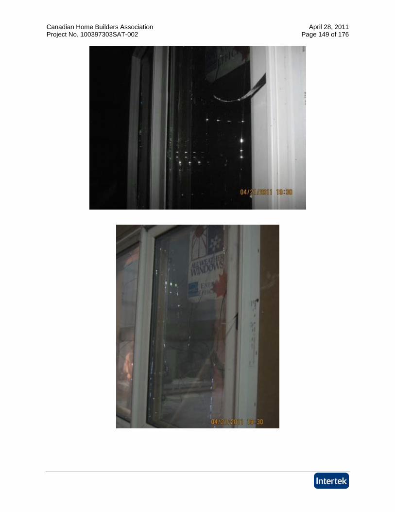
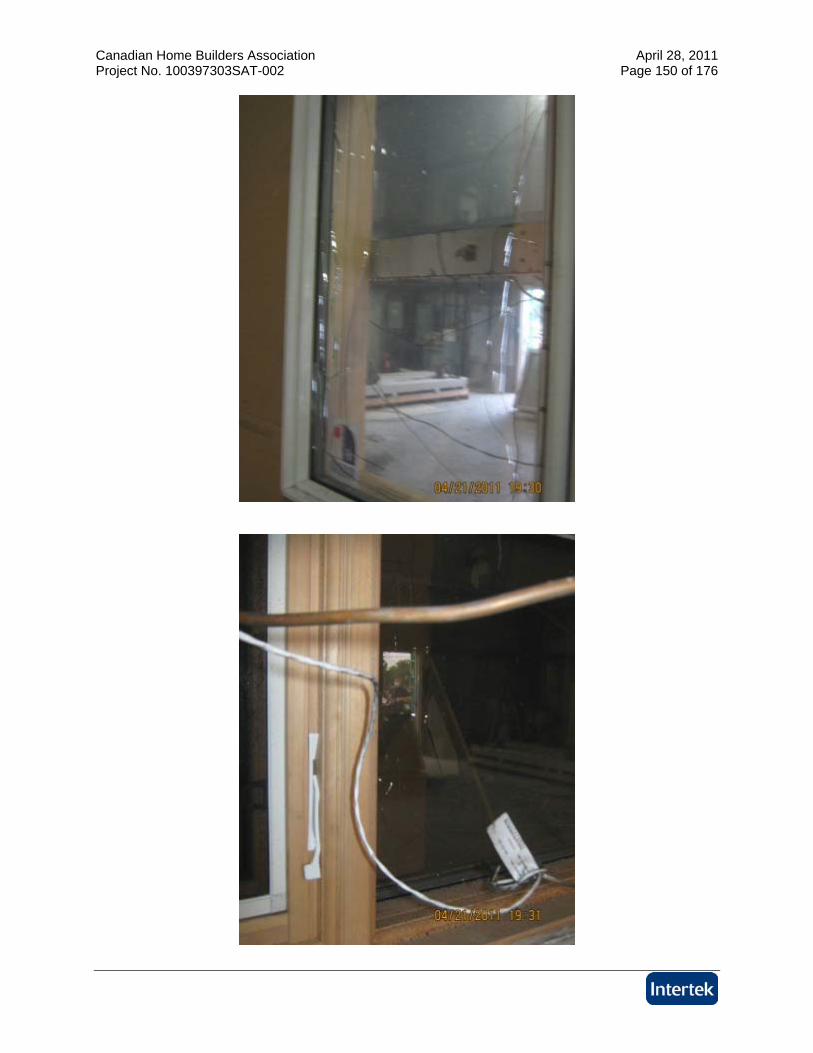
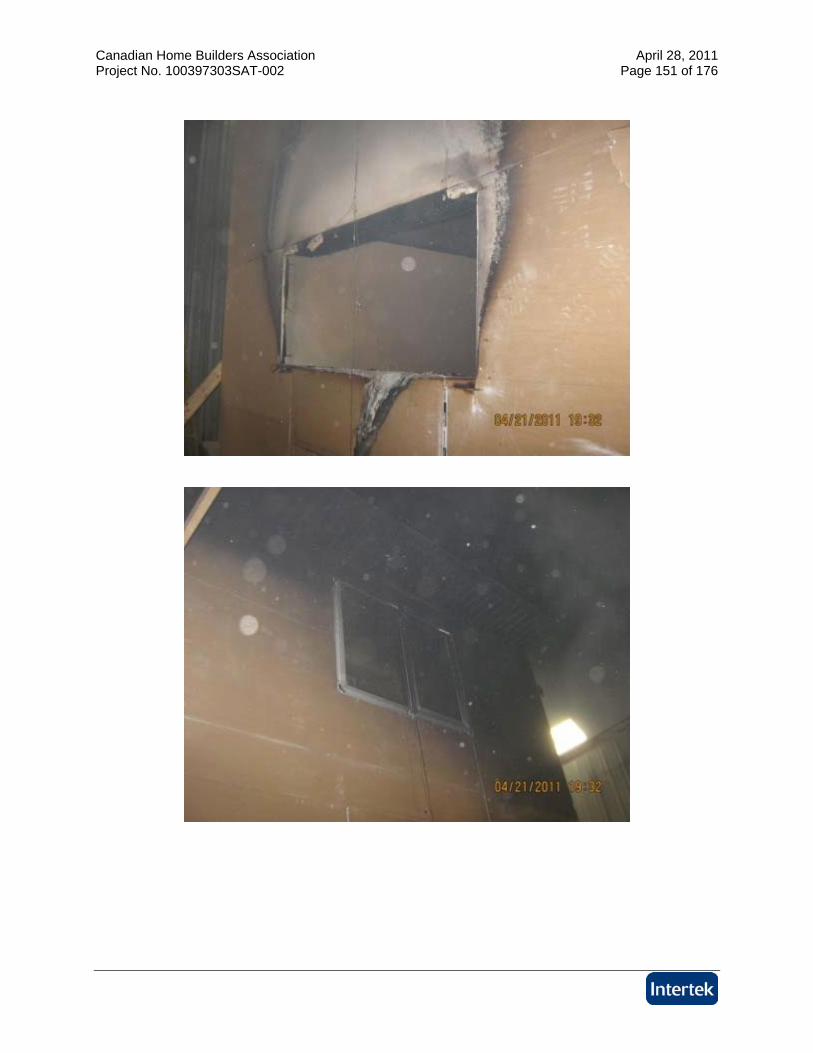
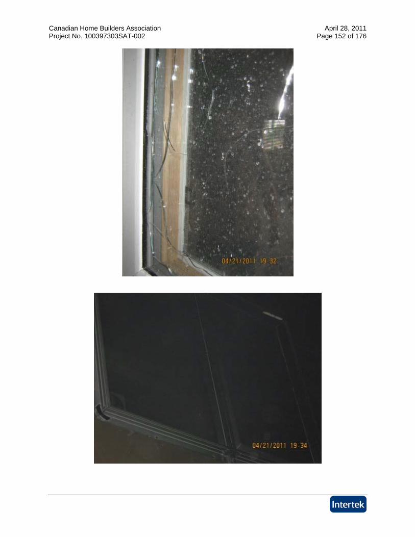
Test C
Canadian Home Builders Association April 28, 2011 Project No. 100397303SAT-002 Page 137 of 176
Canadian Home Builders Association April 28, 2011 Project No. 100397303SAT-002 Page 138 of 176
Canadian Home Builders Association April 28, 2011 Project No. 100397303SAT-002 Page 139 of 176
Canadian Home Builders Association April 28, 2011 Project No. 100397303SAT-002 Page 140 of 176
Canadian Home Builders Association April 28, 2011 Project No. 100397303SAT-002 Page 141 of 176
Canadian Home Builders Association April 28, 2011 Project No. 100397303SAT-002 Page 142 of 176
Canadian Home Builders Association April 28, 2011 Project No. 100397303SAT-002 Page 143 of 176
Canadian Home Builders Association April 28, 2011 Project No. 100397303SAT-002 Page 144 of 176
Canadian Home Builders Association April 28, 2011 Project No. 100397303SAT-002 Page 145 of 176
Canadian Home Builders Association April 28, 2011 Project No. 100397303SAT-002 Page 146 of 176
Canadian Home Builders Association April 28, 2011 Project No. 100397303SAT-002 Page 147 of 176
Canadian Home Builders Association April 28, 2011 Project No. 100397303SAT-002 Page 148 of 176
Canadian Home Builders Association April 28, 2011 Project No. 100397303SAT-002 Page 149 of 176
Canadian Home Builders Association April 28, 2011 Project No. 100397303SAT-002 Page 150 of 176
Canadian Home Builders Association April 28, 2011 Project No. 100397303SAT-002 Page 151 of 176
Canadian Home Builders Association April 28, 2011 Project No. 100397303SAT-002 Page 152 of 176
Canadian Home Builders Association April 28, 2011 Project No. 100397303SAT-002 Page 153 of 176
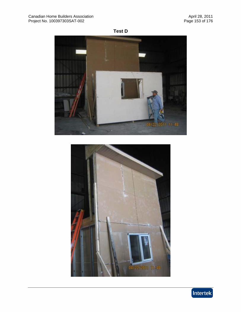
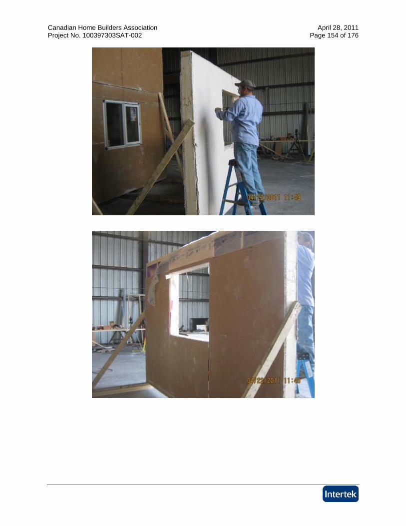
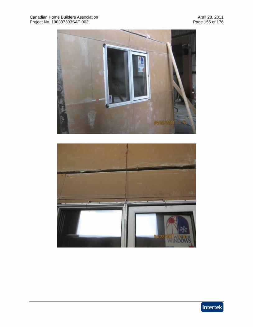
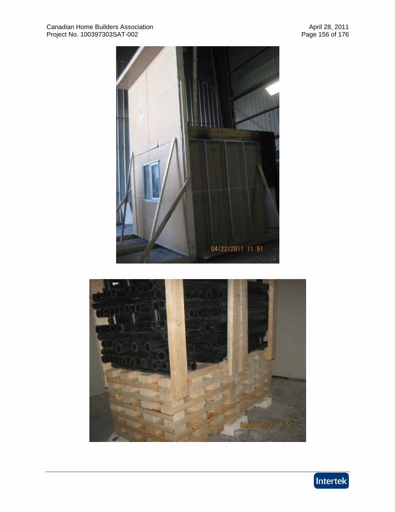
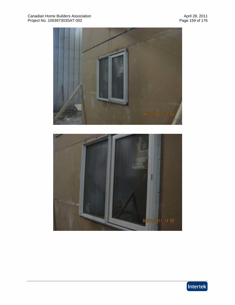
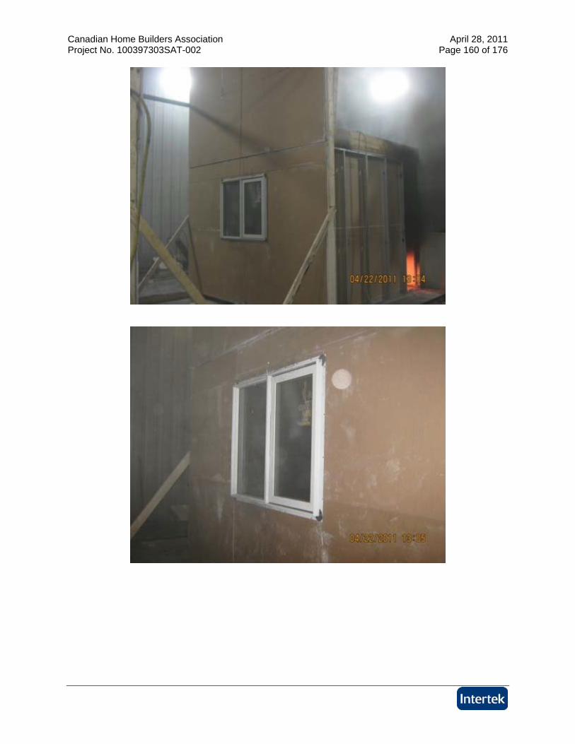
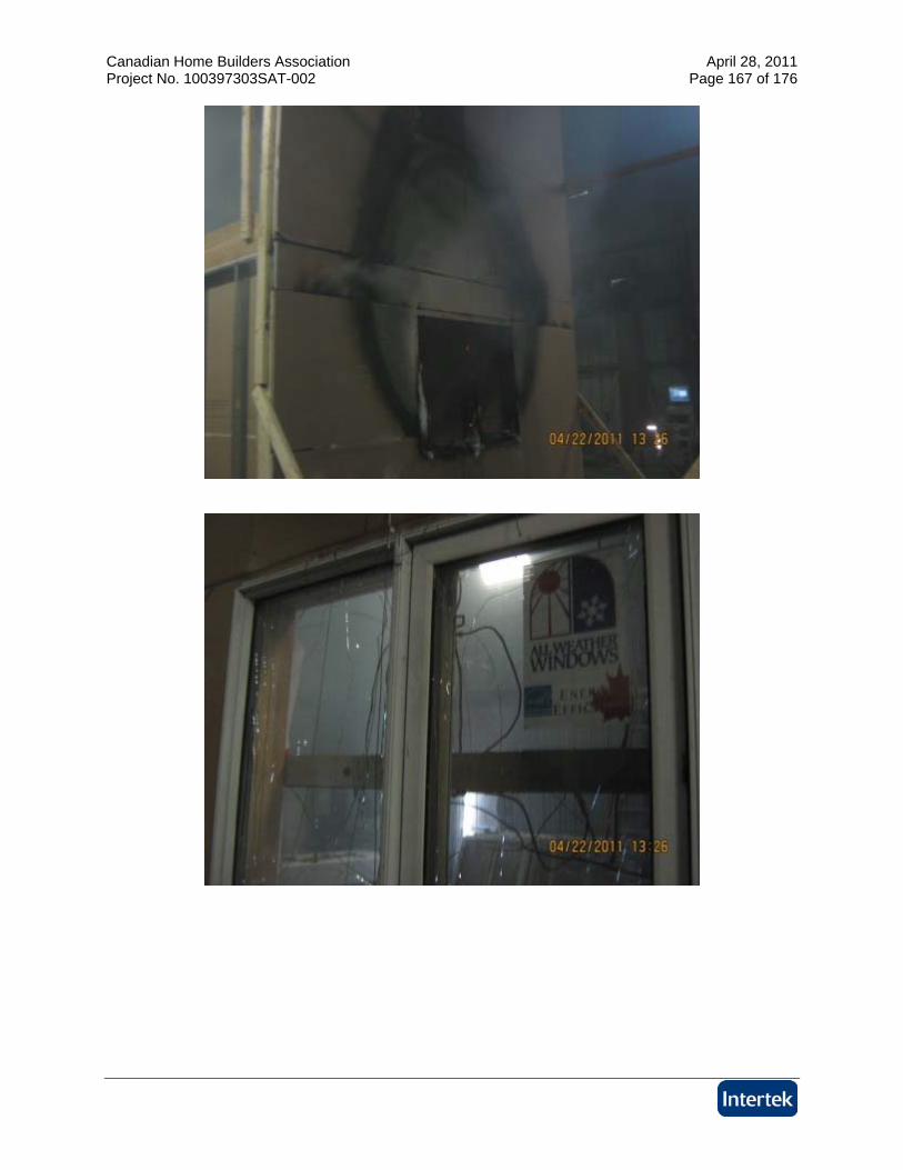
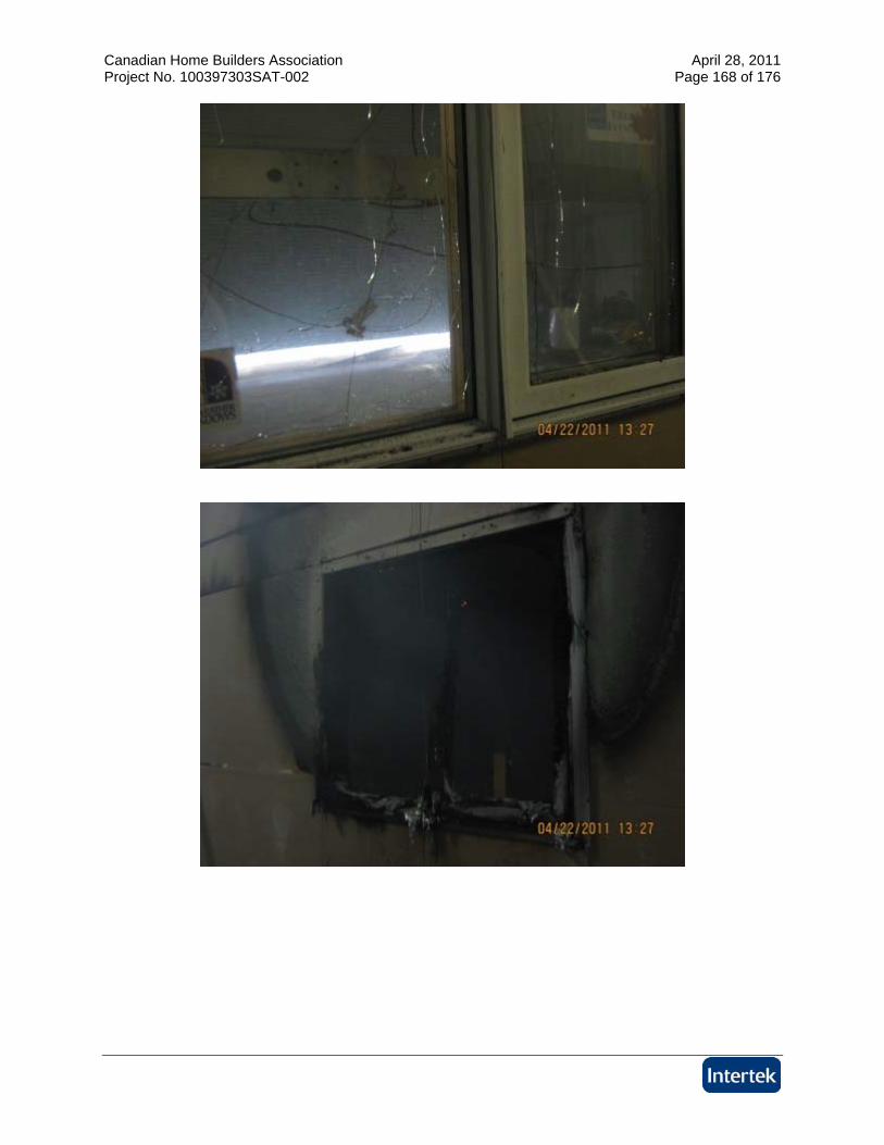
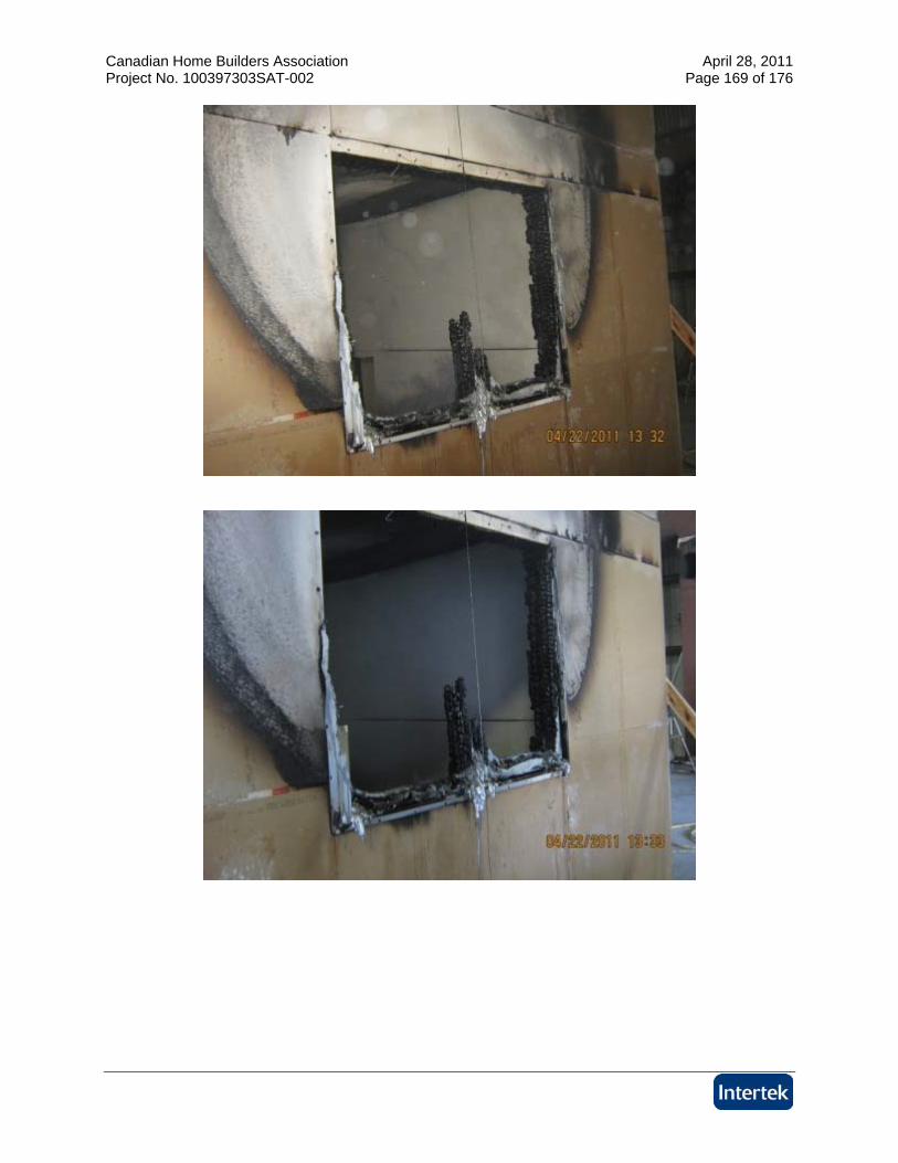
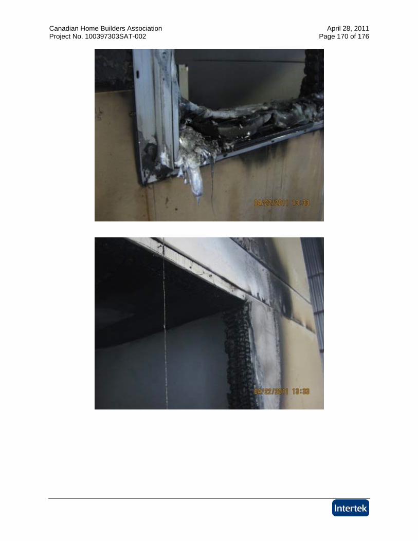
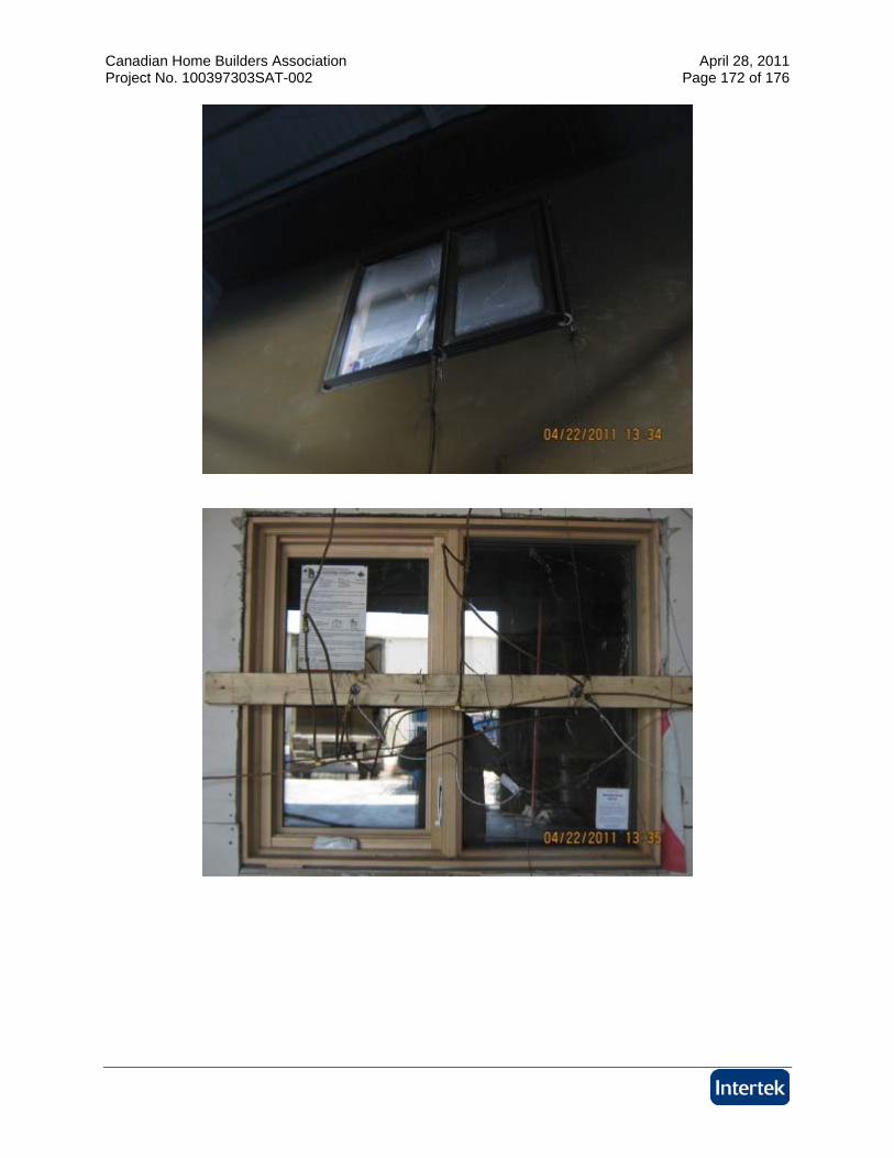
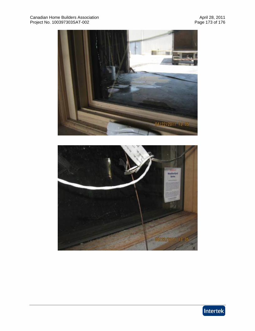
Test D
Canadian Home Builders Association April 28, 2011 Project No. 100397303SAT-002 Page 154 of 176
Canadian Home Builders Association April 28, 2011 Project No. 100397303SAT-002 Page 155 of 176
Canadian Home Builders Association April 28, 2011 Project No. 100397303SAT-002 Page 156 of 176
Canadian Home Builders Association April 28, 2011 Project No. 100397303SAT-002 Page 157 of 176
Canadian Home Builders Association April 28, 2011 Project No. 100397303SAT-002 Page 158 of 176
Canadian Home Builders Association April 28, 2011 Project No. 100397303SAT-002 Page 159 of 176
Canadian Home Builders Association April 28, 2011 Project No. 100397303SAT-002 Page 160 of 176
Canadian Home Builders Association April 28, 2011 Project No. 100397303SAT-002 Page 161 of 176
Canadian Home Builders Association April 28, 2011 Project No. 100397303SAT-002 Page 162 of 176
Canadian Home Builders Association April 28, 2011 Project No. 100397303SAT-002 Page 163 of 176
Canadian Home Builders Association April 28, 2011 Project No. 100397303SAT-002 Page 164 of 176
Canadian Home Builders Association April 28, 2011 Project No. 100397303SAT-002 Page 165 of 176
Canadian Home Builders Association April 28, 2011 Project No. 100397303SAT-002 Page 166 of 176
Canadian Home Builders Association April 28, 2011 Project No. 100397303SAT-002 Page 167 of 176
Canadian Home Builders Association April 28, 2011 Project No. 100397303SAT-002 Page 168 of 176
Canadian Home Builders Association April 28, 2011 Project No. 100397303SAT-002 Page 169 of 176
Canadian Home Builders Association April 28, 2011 Project No. 100397303SAT-002 Page 170 of 176
Canadian Home Builders Association April 28, 2011 Project No. 100397303SAT-002 Page 171 of 176
Canadian Home Builders Association April 28, 2011 Project No. 100397303SAT-002 Page 172 of 176
Canadian Home Builders Association April 28, 2011 Project No. 100397303SAT-002 Page 173 of 176
Canadian Home Builders Association April 28, 2011 Project No. 100397303SAT-002 Page 174 of 176
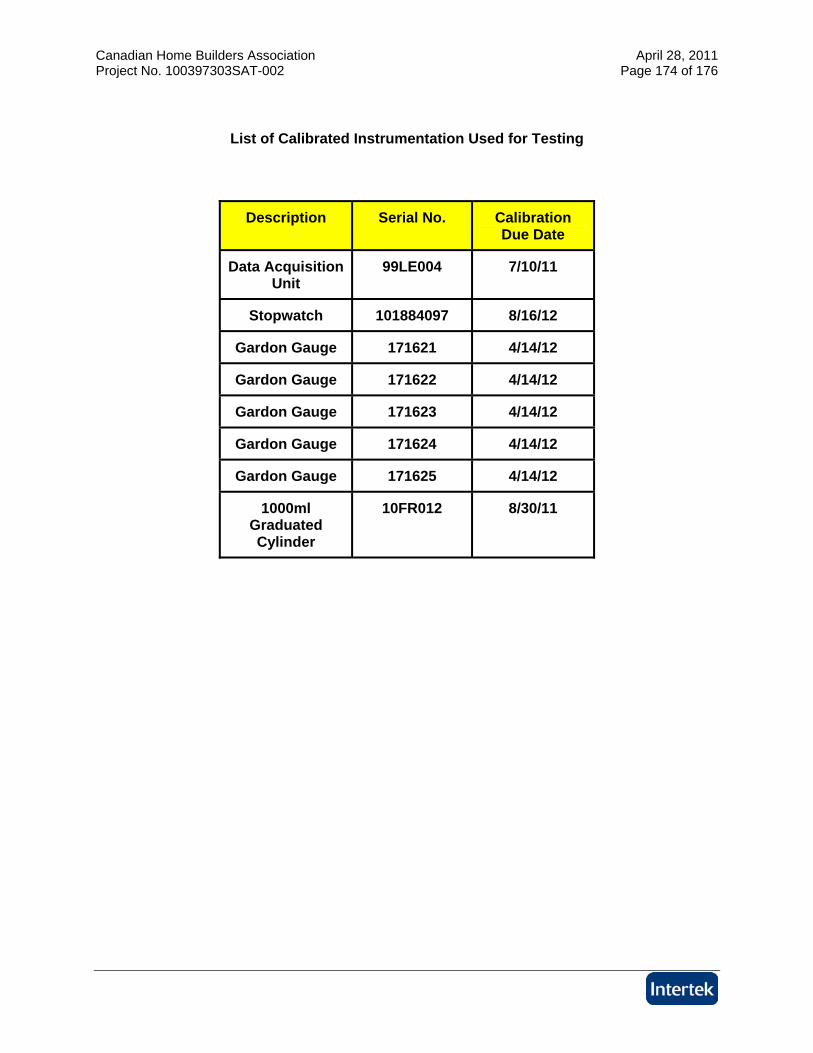
List of Calibrated Instrumentation Used for Testing
Description Serial No. Calibration Due Date
Data Acquisition Unit
99LE004 7/10/11
Stopwatch 101884097 8/16/12
Gardon Gauge 171621 4/14/12
Gardon Gauge 171622 4/14/12
Gardon Gauge 171623 4/14/12
Gardon Gauge 171624 4/14/12
Gardon Gauge 171625 4/14/12
1000ml Graduated Cylinder
10FR012 8/30/11

Canadian Home Builders Association April 28, 2011 Project No. 100397303SAT-002 Page 175 of 176
Referenced Report Full-Scale Fire Study of Spatial Separtion
Research Report: IRC-RR-195
Dated: May 19, 2005
Authored by: Joseph Z. Su and Bruce C. Taber
Published by: Institute for Research In Construction and National Research Council Canada, Ottawa, Canada K1A 0R6

Canadian Home Builders Association April 28, 2011 Project No. 100397303SAT-002 Page 176 of 176
REVISION SUMMARY
DATE SUMMARY April 28, 2011 Original Issue Date