Embed Size (px)
Citation preview

Report No.:TZ210902575-E
TEST REPORT
FCC PART 15B
Report Reference No. ..................... : TZ210902575-E
Compiled by
( position+printed name+signature) .. : File administrators Nancy Li
Name of the organization performing the tests
( position+printed name+signature) .. : Technique principal Hugo Chen
Approved by
( position+printed name+signature) .. : Manager Andy Zhang
Date of issue ..................................... : 2021/9/28
Representative Laboratory Name .... : Shenzhen Tongzhou Testing Co.,Ltd
Address ............................................. : 1th Floor, Building 1, Haomai High-tech Park, Huating Road 387, Dalang Street, Longhua, Shenzhen, China
Applicant’s name ............................ : Shenzhen Whakin Innovation Technology Co.,ltd
Address ............................................. : 4/F, L Bldg, Jingtie Technology Industrial Park, No.49 Changjiangpu Rd. HeAo Community Longgang district, Shenzhen 518116, China
Test specification:
Standard ........................................... : FCC Part 15B
TRF Originator .................................. : Shenzhen Tongzhou Testing Co.,Ltd
Master TRF ....................................... : Dated 2012-06
Shenzhen Tongzhou Testing Co.,Ltd All rights reserved.
This publication may be reproduced in whole or in part for non-commercial purposes as long as the Shenzhen Tongzhou Testing Co.,Ltd is acknowledged as copyright owner and source of the material. Shenzhen Tongzhou Testing Co.,Ltd takes no responsibility for and will not assume liability for damages resulting from the reader's interpretation of the reproduced material due to its placement and context.
Test item description .................... : Phototherapy lamp
Trade Mark ....................................... : N/A
Model/Type reference ....................... : HL15
Listed Models .................................. : N/A
Manufacturer .................................... : Shenzhen Whakin Innovation Technology Co.,ltd
Power Supply…………………………: DC 12V by adapter
Result ................................................ : Pass Draft

Page 2 of 26 Report No.: TZ210902575-E
T E S T R E P O R T
Test Report No. : TZ210902575-E 2021/9/28
______________________________________________________________________________________________
Date of issue
Equipment under Test : Phototherapy lamp
Model /Type : HL15
Listed Models : N/A
Applicant : Shenzhen Whakin Innovation Technology Co.,ltd
Address : 4/F, L Bldg, Jingtie Technology Industrial Park, No.49 Changjiangpu Rd. HeAo Community Longgang district, Shenzhen 518116, China
Manufacturer : Shenzhen Whakin Innovation Technology Co.,ltd
Address : 4/F, L Bldg, Jingtie Technology Industrial Park, No.49 Changjiangpu Rd. HeAo Community Longgang district, Shenzhen 518116, China
Test Result according to the
standards on page 4:
Pass
The test report merely corresponds to the test sample. It is not permitted to copy extracts of these test result without the written permission of the test laboratory.
Draft
Page 3 of 26 Report No.: TZ210902575-E
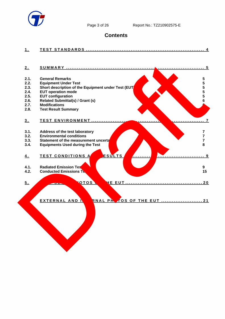
Contents
1 . T E S T S T A N D A R D S . . . . . . . . . . . . . . . . . . . . . . . . . . . . . . . . . . . . . . . . . . . . . . . . . . . . . . . . . . . . . . . . . . 4
2 . S U M M A R Y . . . . . . . . . . . . . . . . . . . . . . . . . . . . . . . . . . . . . . . . . . . . . . . . . . . . . . . . . . . . . . . . . . . . . . . . . . . . . 5
2.1. General Remarks 5 2.2. Equipment Under Test 5 2.3. Short description of the Equipment under Test (EUT) 5 2.4. EUT operation mode 5 2.5. EUT configuration 5 2.6. Related Submittal(s) / Grant (s) 6 2.7. Modifications 6 2.8. Test Result Summary 6
3 . T E S T E N V I R O N M E N T . . . . . . . . . . . . . . . . . . . . . . . . . . . . . . . . . . . . . . . . . . . . . . . . . . . . . . . . . . . . . . . 7
3.1. Address of the test laboratory 7 3.2. Environmental conditions 7 3.3. Statement of the measurement uncertainty 7 3.4. Equipments Used during the Test 8
4 . T E S T C O N D I T I O N S A N D R E S U L T S . . . . . . . . . . . . . . . . . . . . . . . . . . . . . . . . . . . . . . . . . . . . . 9
4.1. Radiated Emission Test 9 4.2. Conducted Emissions Test 15
5 . T E S T S E T U P P H O T O S O F T H E E U T . . . . . . . . . . . . . . . . . . . . . . . . . . . . . . . . . . . . . . . . . . . 2 0
6 . E X T E R N A L A N D I N T E R N A L P H O T O S O F T H E E U T . . . . . . . . . . . . . . . . . . . . . . . 2 1
Draft

Page 4 of 26 Report No.: TZ210902575-E
1 . T E S T S T A N D A R D S The tests were performed according to following standards: FCC Rules Part 15 Subpart B Unintentional Radiators ANSI C63.4-2014 American National Standard for Methods of Measurement of Radio-Noise Emissions from Low-Voltage Electrical and Electronic Equipment in the Range of 9 kHz to 40 GHz
Draft

Page 5 of 26 Report No.: TZ210902575-E
2 . S U M M A R Y
2.1. General Remarks
Date of receipt of test sample : 2021/9/21 Testing commenced on : 2021/9/21 Testing concluded on : 2021/9/27
2.2. Equipment Under Test
Power supply system utilised
Power supply voltage ○ 120V / 60 Hz ○ 115V / 60Hz
○ 12 V DC ○ 24 V DC
● Other (specified in blank below)
DC 12V by adapter
2.3. Short description of the Equipment under Test (EUT)
Phototherapy lamp. For more details, refer to the user’s manual of the EUT.
2.4. EUT operation mode
The EUT has been tested under typical operating condition.
Mode(s) Description Conect to GRP
1 Normal Working+Charging No
2.5. EUT configuration
The following peripheral devices and interface cables were connected during the measurement:
○ - supplied by the manufacturer
● - supplied by the lab
○ Adapter Model : TPQ-236A120100UW01
Input : AC 100-240V 50/60Hz 0.4A
Output : DC 12V, 1A
○ Adapter Model : K12V120100U
Input : AC 100-240V 50/60Hz 0.35A
Output : DC 12V, 1A
Draft

Page 6 of 26 Report No.: TZ210902575-E
2.6. Related Submittal(s) / Grant (s) This test report is intended for HL15 filing to comply with the FCC Part 15, Subpart B Rules.
2.7. Modifications
No modifications were implemented to meet testing criteria.
2.8. Test Result Summary
Test Item Test Requirement Standard Paragrph Result Radiated Emission FCC PART 15 Section 15.109 PASS
Conducted Emission FCC PART 15 Section 15.107 PASS
Draft

Page 7 of 26 Report No.: TZ210902575-E
3 . T E S T E N V I R O N M E N T
3.1. Address of the test laboratory
Shenzhen Tongzhou Testing Co.,Ltd 1th Floor, Building 1, Haomai High-tech Park, Huating Road 387, Dalang Street, Longhua, Shenzhen,
China The sites are constructed in conformance with the requirements of ANSI C63.7, ANSI C63.4 (2014) and CISPR Publication 22.
3.2. Environmental conditions
During the measurement the environmental conditions were within the listed ranges:
Temperature: 15-35 ° C
Humidity: 30-60 %
Atmospheric pressure: 950-1050mbar
3.3. Statement of the measurement uncertainty
The data and results referenced in this document are true and accurate. The reader is cautioned that there may be errors within the calibration limits of the equipment and facilities. The measurement uncertainty was calculated for all measurements listed in this test report acc. to CISPR 16 - 4 „Specification for radio disturbance and immunity measuring apparatus and methods – Part 4: Uncertainty in EMC Measurements“ and is documented in the Shenzhen Tongzhou Testing Co.,Ltd quality system acc. to DIN EN ISO/IEC 17025. Furthermore, component and process variability of devices similar to that tested may result in additional deviation. The manufacturer has the sole responsibility of continued compliance of the device. Hereafter the best measurement capability for Shenzhen Tongzhou Testing Co.,Ltd y is reported:
Test Item Frequency Range Uncertainty Note
Radiation Uncertainty 30MHz~1000MHz ±3.92dB (1)
1GHz~40GHz ±4.28dB (1)
Conduction Uncertainty : 150kHz~30MHz ±2.71dB (1) (1). This uncertainty represents an expanded uncertainty expressed at approximately the 95% confidence level using a coverage factor of k=2. Draf
t

Page 8 of 26 Report No.: TZ210902575-E
3.4. Equipments Used during the Test
Conducted emission
Item
Test Equipment Manufacturer Model No. Serial No. Last Cal. Cal. Due
1 EMI Test Receiver ROHDE & SCHWARZ
ESCI 100849/003 2021/1/4 2022/1/3
2 Artificial Mains ROHDE & SCHWARZ
ENV 216 101333-IP 2021/1/4 2022/1/3
3 EMI Test Software ROHDE & SCHWARZ
ESK1 V1.71 N/A N/A
Radiated emission
Item
Test Equipment Manufacturer Model No. Serial No. Last Cal. Cal. Due
1 Test Receiver R&S ESCI-7 100849/003 2021/1/4 2022/1/3
2 wideband Antenna schwarzbeck VULB 9163 958 2019/11/16 2022/11/15
3 Horn Antenna schwarzbeck 9120D-1141 1574 2019/11/16 2022/11/15
4 Amplifier schwarzbeck BBV 9743 209 2021/1/4 2022/1/3
5 Amplifier Tonscend TSAMP-0518SE
-- 2021/1/4 2022/1/3
6 Postional Controller MF MF7802 -- -- --
7 RE test software Tonscend JS32-RE V2.0.2.0 -- --
Draft

Page 9 of 26 Report No.: TZ210902575-E
4 . T E S T C O N D I T I O N S A N D R E S U L T S
4.1. Radiated Emission Test
TEST CONFIGURATION
(A) Radiated Emission Test Set-Up, Frequency Below 30MHz
(B) Radiated Emission Test Set-Up, Frequency below 1000MHz
(C) Radiated Emission Test Set-Up, Frequency above 1000MHz
1m to 4m
Test
Receiver
EUT
3m
0.8m
Turntable
Coaxial Cable Ground Plane
Test
Receiver
EUT
3m Turntable
Coaxial Cable Ground Plane
0.8 m
Draft

Page 10 of 26 Report No.: TZ210902575-E
Field Strength Calculation
The field strength is calculated by adding the Antenna Factor and Cable Factor and subtracting the
Amplifier Gain and Duty Cycle Correction Factor(if any) from the measured reading. The basic equation with a
sample calculation is as follows:
FS = RA + AF + CL - AG
Where FS = Field Strength CL = Cable Attenuation Factor (Cable Loss)
RA = Reading Amplitude AG = Amplifier Gain
AF = Antenna Factor
RADIATION LIMIT For unintentional device, according to § 15.109(a), except for Class A digital devices, the field strength of radiated emissions from unintentional radiators at a distance of 3 meters shall not exceed the following
values:
Frequency
(MHz)
Distance
(Meters)
Radiated
(dBμV/m)
Radiated
(μV/m)
30-88 3 40.0 100
88-216 3 43.5 150
216-960 3 46.0 200
Above 960 3 54.0 500
For intentional device, according to § 15.209(a), the general requirement of field strength of radiated emissions from intentional radiators at a distance of 3 meters shall not exceed the above table. Test Procedure
1. The EUT is placed on a turntable, which is 0.8m above ground plane. 2. The turntable shall be rotated for 360 degrees to determine the position of maximum emission level. 3. EUT is set 3m away from the receiving antenna, which is varied from 1m to 4m to find out the highest
emissions. 4. Maximum procedure was performed on the six highest emissions to ensure EUT compliance. 5. And also, each emission was to be maximized by changing the polarization of receiving antenna both
horizontal and vertical. 6. Repeat above procedures until the measurements for all frequencies are complete. Radiation Test Results
Below 1000MHz
Draft

Page 11 of 26 Report No.: TZ210902575-E
Polarization: Horizontal (Test with Adapter: TPQ-236A120100UW01)
Draft

Page 12 of 26 Report No.: TZ210902575-E
Polarization: Vertical
Draft

Page 13 of 26 Report No.: TZ210902575-E
Polarization: Horizontal (Test with Adapter: K12V120100U)
Draft

Page 14 of 26 Report No.: TZ210902575-E
Polarization: Vertical
Draft

Page 15 of 26 Report No.: TZ210902575-E
4.2. Conducted Emissions Test
TEST CONFIGURATION
TEST PROCEDURE 1 The equipment was set up as per the test configuration to simulate typical actual usage per the user’s
manual. The EUT is a tabletop system, a wooden table with a height of 0.8 meters is used and is placed on the ground plane as per ANSI C63.4.
2 Support equipment, if needed, was placed as per ANSI C63.4. 3 All I/O cables were positioned to simulate typical actual usage as per ANSI C63.4. 4 The EUT received power through a Line Impedance Stabilization Network (LISN) which supplied power
source and was grounded to the ground plane. 5 All support equipments received AC power from a second LISN, if any. 6 The EUT test program was started. Emissions were measured on each current carrying line of the EUT
using a spectrum Analyzer / Receiver connected to the LISN powering the EUT. The LISN has two monitoring points: Line 1 (Hot Side) and Line 2 (Neutral Side). Two scans were taken: one with Line 1 connected to Analyzer / Receiver and Line 2 connected to a 50 ohm load; the second scan had Line 1 connected to a 50 ohm load and Line 2 connected to the Analyzer / Receiver.
7 Analyzer / Receiver scanned from 150 KHz to 30MHz for emissions in each of the test modes. 8 During the above scans, the emissions were maximized by cable manipulation. Conducted Power Line Emission Limit
For unintentional device, according to § 15.107(a) Line Conducted Emission Limits is as following:
Maximum RF Line Voltage (dBμV) Frequency
(MHz) CLASS A CLASS B
Q.P. Ave. Q.P. Ave. 0.15 - 0.50 79 66 66-56* 56-46*
0.50 - 5.00 73 60 56 46
5.00 - 30.0 73 60 60 50
* Decreasing linearly with the logarithm of the frequency
For intentional device, according to §15.207(a) Line Conducted Emission Limit is same as above table.
TEST RESULTS
Draft

Page 16 of 26 Report No.: TZ210902575-E
(Test with Adapter: TPQ-236A120100UW01)
Draft

Page 17 of 26 Report No.: TZ210902575-E
Draft

Page 18 of 26 Report No.: TZ210902575-E
(Test with Adapter: K12V120100U)
Draft

Page 19 of 26 Report No.: TZ210902575-E
Draft

Page 20 of 26 Report No.: TZ210902575-E
5 . T e s t S e t u p P h o t o s o f t h e E U T
Photograph – Conducted Emission Test Setup
Photograph – Radiated Emission Test Setup-Below 1GHz
Draft

Page 21 of 26 Report No.: TZ210902575-E
6 . E x t e r n a l a n d I n t e r n a l P h o t o s o f t h e E U T
External Photos
Draft

Page 22 of 26 Report No.: TZ210902575-E
Draf
t

Page 23 of 26 Report No.: TZ210902575-E
Draf
t

Page 24 of 26 Report No.: TZ210902575-E
Draft

Page 25 of 26 Report No.: TZ210902575-E
Internal Photos
Draft

Page 26 of 26 Report No.: TZ210902575-E
.....................End of Report....................... Draft