Embed Size (px)
Citation preview
Document of the World Bank
Report No: AUS8579 - 3
.
United Mexican States
MX TF Carbon Capture, Utilization and Storage Development in Mexico
Combining CO2 Enhanced Oil Recovery with Permanent Storage in Mexico
. June 10, 2016
. GEE04
LATIN AMERICA AND CARIBBEAN
.

.
.
Standard Disclaimer:
.
This volume is a product of the staff of the International Bank for Reconstruction and Development/ The World Bank. The findings, interpretations, and conclusions expressed in this paper do not necessarily reflect the views of the Executive Directors of The World Bank or the governments they represent. The World Bank does not guarantee the accuracy of the data included in this work. The boundaries, colors, denominations, and other information shown on any map in this work do not imply any judgment on the part of The World Bank concerning the legal status of any territory or the endorsement or acceptance of such boundaries.
.
Copyright Statement:
.
The material in this publication is copyrighted. Copying and/or transmitting portions or all of this work without permission may be a
violation of applicable law. The International Bank for Reconstruction and Development/ The World Bank encourages dissemination
of its work and will normally grant permission to reproduce portions of the work promptly.
For permission to photocopy or reprint any part of this work, please send a request with complete information to the Copyright
Clearance Center, Inc., 222 Rosewood Drive, Danvers, MA 01923, USA, telephone 978-750-8400, fax 978-750-4470,
http://www.copyright.com/.
All other queries on rights and licenses, including subsidiary rights, should be addressed to the Office of the Publisher, The World
Bank, 1818 H Street NW, Washington, DC 20433, USA, fax 202-522-2422, e-mail [email protected].
Combining CO2 Enhanced Oil Recovery with Permanent Storage in Mexico
FINAL REPORT Review of Current Status and Identification of Key Issues World Bank Selection No. 1158524 Battelle Project #100062989 Submitted by:
Dr. Neeraj Gupta (614-424-3820, [email protected]) Lydia Cumming (614-424-7778, [email protected]) Battelle Memorial Institute 505 King Avenue Columbus, OH 43201
Submitted to:
The World Bank Group 1818 H Street NW Washington, DC 20433
June 10, 2016
Final Report Page ii
Combining CO2 Enhanced Oil Recovery with Permanent Storage in Mexico
Final Report
Review of Current Status and Identification of Key Issues
Neeraj Gupta, Lydia Cumming, Joel Sminchak, Ashwin Pasumarti, and Priya Ravi Ganesh
Battelle Memorial Institute
Columbus, Ohio, USA
Robert F Van Voorhees PLLC
Washington, DC
June 10, 2016

Final Report Page iii
Notice
Battelle does not engage in research for advertising, sales promotion, or endorsement of our clients’ interests including raising investment capital or recommending investments decisions, or other publicity purposes, or for any use in litigation.
Battelle endeavors at all times to produce work of the highest quality, consistent with our contract commitments. However, because of the research and/or experimental nature of this work the client undertakes the sole responsibility for the consequence of any use or misuse of, or inability to use, any information, apparatus, process or result obtained from Battelle, and Battelle, its employees, officers, or Trustees have no legal liability for the accuracy, adequacy, or efficacy thereof.

Final Report Page iv
Acknowledgements
This project was conducted under funding from The World Bank and in collaboration with the Project Task
Force, which includes representatives of PEMEX, SENER, the World Bank, and other organizations. The
World Bank staff included Dr. Natalia Kulichenko as the project manager along with support from Engr.
Guillermo Hernández González, Dr. Moisés Dávila Serrano, and Dr. Frank Mourits. The authors also wish
to extend their sincere appreciation to Dr. Fernando Rodríguez de la Garza and his staff at PEMEX, as
well as Engr. Jazmín Mota Nieto, SENER, for providing invaluable guidance, outreach, and logistical
support. The authors of this report also would like to acknowledge other individual members of the Project
Task Force whose participation and guidance helped make the project a success, including Engr. Erika
Guzman Torres, SEMARNAT, and Engr. Grecia Ramírez Ovalle, CNH.
Battelle was responsible for the overall project execution, including project management and technical
analysis. Dr. Neeraj Gupta was the Battelle Principal Investigator for this work and Ms. Lydia Cumming
provided project management and technical coordination between team members. Other Battelle team
members contributing to this report included Ms. Priya Ravi Ganesh, Mr. Joel Sminchak, Dr. Srikanta
Mishra, Mr. Ashwin Pasumarti, Dr. Andrew Duguid and Ms. Jacqueline Gerst. Battelle’s team members
for this project included Mr. Robert Van Voorhees, who provided valuable guidance on international
frameworks and regulatory requirements, and Engr. Pablo Diaz-Herrera, who provided in-country
logistical and technical support.
The authors are thankful to a number of subject matter experts who shared valuable time and insight
during interviews, including Mr. Neil Wildgust, Mr. Charles Gorecki, Mr. Ed Steadman, Mr. John Hamling,
Mr. Adam Wygant, Mr. Nigel Jenvey, Dr. Susan Hovorka, and Mr. Sasha Mackler.
Final Report Page v
Executive Summary
The goal of the current project is to review state-of-the-art practices related to combining carbon dioxide
(CO2) enhanced oil recovery (EOR) with geologic storage for carbon capture, utilization and storage
(CCUS) in Mexico. This was accomplished by an assessment of the requirements a CO2-EOR project
must satisfy in order to qualify as a permanent storage project to earn carbon credits. The material
presented is based on review of latest literature, discussions with relevant experts, as well as Battelle’s
direct experiences from multiple in-house geologic CO2 storage projects. The report focuses on the key
technical and practical considerations and provides an overview of related technologies for economic and
efficient CO2-EOR storage.
The technology and operational practices for CCUS have been developed over decades of CO2-EOR
experience established in the oil and gas industry. Hence, the key barriers and uncertainties in
accounting for associated CO2 storage during CO2-EOR operations are not technical but economic and
policy-related. While economic favorability can be improved by investing in improvements to the current
CO2 infrastructure, strong constructive policy measures for geologic CO2 storage are also important.
CO2-EOR projects demonstrating storage of anthropogenic CO2 in Mexico may be eligible to provide
carbon credits. The minimum requirements to gain storage credits according to protocols stated in the
United Nations Framework Convention on Climate Change Clean Development Mechanism (CDM),
California Cap-and-Trade Regulation Instructional Guidance, American Carbon Registry, and U.S.
Environmental Protection Agency regulatory guidance were compared and contrasted. The protocols
typically outline requirements as performance measures without prescribing technologies to meet these
requirements. Accordingly, there is significant flexibility for the project proponent to fashion the project
details and submit for approval plans that describe how requirements will be met.
Many of the requirements for storage within EOR will be built on the operator’s business as usual, but
others will require additional effort to confirm storage integrity. Secure permanent geologic storage of CO2
must be documented by operators by showing how sites have been characterized and existing wells
evaluated to ensure containment. EOR projects may require some operational or reporting modifications
to qualify for regulatory and other credit-related requirements. Additional monitoring or reporting, for
instance, may be needed to track and demonstrate CO2 storage beyond typical EOR operations.
Likewise, modeling efforts may be modified to optimize storage and for use as a tool to show storage
integrity in the reservoir of interest.
The monitoring, reporting and verification (MRV) plan to track the CO2 storage within the EOR project
boundaries and developed in consultation with the pertinent regulatory and credit granting agencies is a
major consideration that helps the operator proactively manage project risks. Because the monitoring
program in any of the protocols mentioned above is derived from risk assessment, the recommendations
for the MRV program presented in this report form a ‘tiered’ approach based on the risks identified.
Primary requirements would be reservoir zone monitoring to adequately track the pressure, temperature
and CO2. Should leakage signals be detected, the second tier of monitoring for leakage detection and
management would be implemented by monitoring above-zone; and, as the third tier, near-surface and
surface monitoring would be implemented.
While the same monitoring and modeling technologies are applicable for CCUS and geologic storage
projects, CCUS project operators may need to make additional investment in monitoring, measurement
and reporting to characterize, manage and ensure long-term integrity of storage as well as optimal EOR
operations. The CO2 quantification and reporting requirements as well as the post-closure obligations are

Final Report Page vi
crucial to provide a pathway to the credit standards that constitute best practices for responsible geologic
storage operations while protecting stakeholder support for the same.
While CO2-EOR projects demonstrating storage of anthropogenic CO2 may be eligible to earn carbon
credits, this study did not identify any CO2-EOR projects with associated storage, or transitioning to
storage without EOR, as having applied for or received credits. The lack of experience with applying CDM
and European Union protocols to CCS projects in general and to EOR projects in particular could prove a
hindrance, as could the absence of any provisions in these protocols that are specifically tailored to oil
field operations. Under the European Union Emission Trading System Directive, an offset project
involving the incidental storage of anthropogenic CO2 in association with an EOR project in Mexico could
be creditworthy if it meets the requirements of the CDM CCS methodology. Because no such projects
have been considered and credited to date, however, uncertainty surrounds the qualification process.
Practical implementation will be indispensable to qualification without imposing untenable economic
costs. Although the ongoing process for developing ISO standards for CO2 capture, transportation and
storage - including incidental storage in association with EOR - promises to provide a better pathway to
credits, final standards are still several years away.
An offset project in Mexico has the potential to qualify for credit for the California Cap-and-Trade
Program; however, significant steps must be accomplished before the availability of credit could be a
reality. First, the California Air Resources Board (ARB) needs to approve a Compliance Offset Protocol
for CO2 geologic sequestration associated with EOR. In addition, that approved protocol must include
Mexico within approved project area. Before that process is completed, it would also be useful to have
California ARB approval of an early action quantification methodology for geologic sequestration
associated with CO2-EOR. This approval could be based on the American Carbon Registry protocol, but
that protocol would need to be expanded to include Mexico in addition to the U.S. and Canada.
Despite the challenges imposed by the evolving regulatory and credit mechanisms, it is widely agreed
that the CO2-EOR projects provide a viable and economically attractive pathway for greenhouse gas
emission reduction and a potential bridge to storage in saline formations. However, there is a need to
build more project experience and test the various credit mechanisms under realistic conditions. For
Mexico, any planned EOR field tests, even if these are huff-n-puff or small-scale pilots offer an early
opportunity to build the practical knowledge and lay the foundation for successful credit accruals for future
full-scale projects. Therefore, it is recommended that the risk management, modeling, monitoring, and
accounting activities identified in this report be implemented and evaluated as a prototype in the
upcoming feasibility tests.
Final Report Page vii
Table of Contents
Acknowledgements ................................................................................................................................... iv
Executive Summary .................................................................................................................................... v
Acronyms ................................................................................................................................................... x
Chapter 1 Introduction .............................................................................................................................. 1
1.1 Background ................................................................................................................................... 1
1.2 Objectives ...................................................................................................................................... 2
Chapter 2 Literature Survey on the State-of-the-Art CO2-EOR Storage .............................................. 3
2.1 Literature Review .......................................................................................................................... 3
2.1.1 Economics ........................................................................................................................... 5
2.1.2 Optimization Strategies ....................................................................................................... 5
2.1.3 Monitoring, Reporting, and Verification Requirements ....................................................... 6
2.1.4 Other Requirements ............................................................................................................ 6
2.2 Interviews ...................................................................................................................................... 9
2.2.1 Consolidated Interview Responses ................................................................................... 10
2.3 Region-Specific Considerations .................................................................................................. 13
2.3.1 Regional Geologic Information .......................................................................................... 13
2.3.2 Regional CO2 Sources ...................................................................................................... 15
2.4 Conclusions ................................................................................................................................. 18
Chapter 3 Identification of Key Issues for CO2-EOR Storage Projects.............................................. 19
3.1 Risk Assessment Options ........................................................................................................... 19
3.1.1 Wellbore Integrity Analysis ................................................................................................ 20
3.1.2 Recommendations ............................................................................................................ 22
3.2 Reservoir Simulations ................................................................................................................. 23
3.2.1 Recommendations ............................................................................................................ 27
3.3 Monitoring, Reporting, and Verification Requirements ............................................................... 27
3.3.1 Recommendations ............................................................................................................ 28
3.4 Accounting ................................................................................................................................... 29
3.4.1 CO2 Accounting and Measurement Systems .................................................................... 32
3.4.2 Metrics for Estimating CO2 Stored in the EOR Fields ....................................................... 33
3.4.3 Recommendations ............................................................................................................ 36
3.5 Post-Injection Monitoring and Site Closure ................................................................................. 37
3.5.1 Recommendations ............................................................................................................ 38
3.6 Economics ................................................................................................................................... 40
3.6.1 Recommendations ............................................................................................................ 41
3.7 Legal and Regulatory Issues....................................................................................................... 41
3.7.1 Recommendations ............................................................................................................ 41
3.8 Recommended Next Steps ......................................................................................................... 42
Final Report Page viii
Chapter 4 International Framework for Receiving Credits ................................................................. 45
4.1 UNFCC Clean Development Mechanism (CDM) ........................................................................ 45
4.2 European Union CCS Directive................................................................................................... 48
4.3 California Offset Credits .............................................................................................................. 48
4.4 American Carbon Registry .......................................................................................................... 50
4.5 Analogous Mechanism: Texas Railroad Commission ................................................................ 53
4.6 Conclusions ................................................................................................................................. 54
4.6.1 Consistent Requirements .................................................................................................. 54
4.6.2 Legal and Regulatory Issues for Qualifying for Credits .................................................... 55
4.6.3 Summary and Concerns ................................................................................................... 55
Chapter 5 References ............................................................................................................................. 57
Appendices
Appendix A: Literature Review Summaries
Appendix B: Workshop Agendas and Participant Lists
Figures
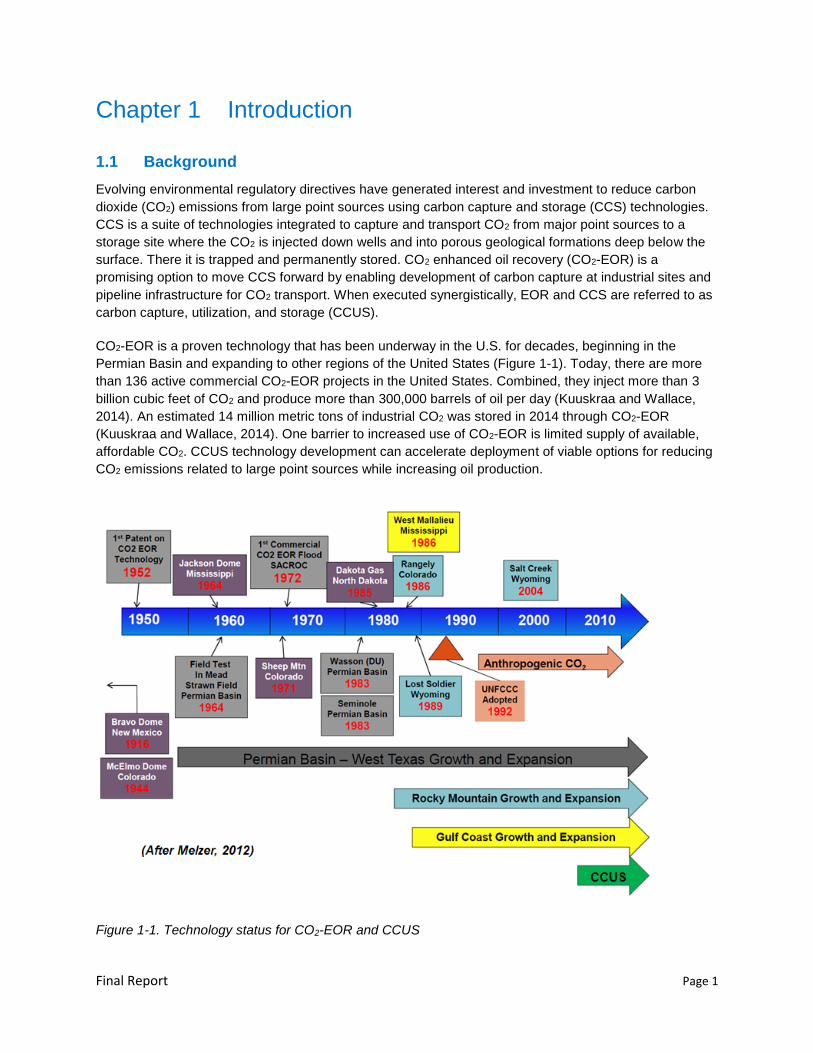
Figure 1-1. Technology status for CO2-EOR and CCUS .......................................................................... 1
Figure 2-1. Research goals and questions set ....................................................................................... 10
Figure 2-2. Zones suitable for CO2 storage in green (top map) and the location of the Cinco Presidentes oilfield (bottom map) in Mexico (Lacy, Serralde et al. 2013) ........................... 14
Figure 2-3. Major PEMEX industrial sources of CO2 (>0.5million metric tons/year) in Cinco Presidentes region (the area of interest) (Source: Lacy, Serralde et al., 2013) .................. 16
Figure 2-4. Distances of PEMEX industrial sources of CO2 to some of the oilfields in the Cinco Presidentes region (Source: Lacy, Serralde et al. 2013) ..................................................... 17
Figure 3-1. Complex CO2 phase behavior changes reservoir response over time during injection period. Example from MRCSP large-scale CO2 injection test in a depleted carbonate reef setting .......................................................................................................... 25
Figure 3-2. Geologic model or SEM schematic flow diagram ................................................................ 26
Figure 3-3. Dynamic modeling inputs consideration for evaluation of CO2-EOR field performance and geologic storage potential ........................................................................ 26
Figure 3-4. Example leakage pathway assessment for MRCSP Large-Scale Injection Project ............ 30
Figure 3-5. Example diagram of closed loop CO2-EOR cycle (source: Gupta et al., 2014) ................... 33
Figure 3-6. Example SCADA data from eight CO2 injection wells .......................................................... 34
Figure 3-7. Example SCADA data from five production wells ................................................................ 35
Figure 3-8. Example graph of cumulative net CO2 retained in EOR units over time .............................. 35
Figure 3-9. Example pressure monitoring and plume during CO2 storage operations and post-injection periods (Graphs illustrate pressure buildup during injection, pressure falloff after injection, and CO2 plume radius stabilization.) ................................................... 39
Final Report Page ix
Figure 3-10. Example of a monitoring schedule for a small-scale research project at an EOR research field at MRCSP Michigan Basin site ..................................................................... 39
Figure 3-11. Hypothetical monitoring scheme ............................................................................................ 42
Tables
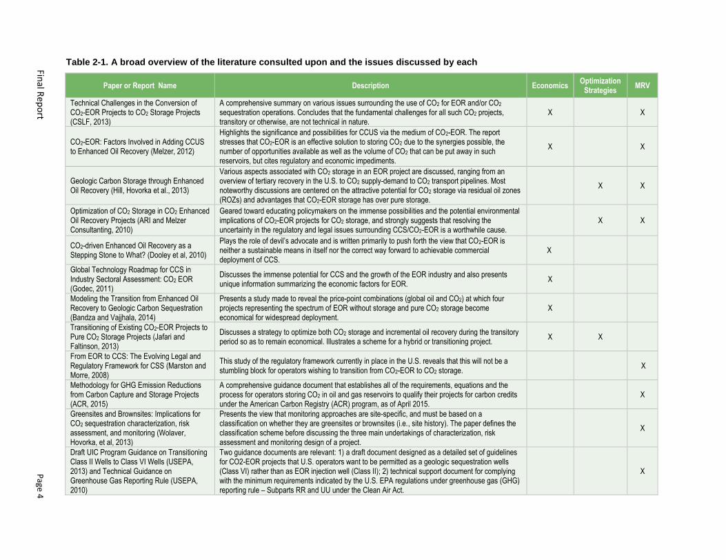
Table 2-1. A broad overview of the literature consulted upon and the issues discussed by each ............. 4
Table 2-2. Comparison of requirements between ACR, CDM, and EPA Rules ......................................... 7
Table 2-3. Interviews ................................................................................................................................... 9
Table 2-4. General subsurface conditions and geologic features in Cinco Presidentes Region .............. 15
Table 3-1. Casing/tubing materials, applications, and limitations ............................................................. 21
Table 3-2. Well integrity items and evaluation factors .............................................................................. 22
Table 3-3. Options for investigation of wellbore integrity at CO2 storage sites ........................................ 23
Table 3-4. Relevant monitoring zones ...................................................................................................... 30
Table 3-5. Example monitoring approaches for CO2 storage site (Source: Al Edian et al., 2015) ........... 31
Table 3-6. Post-injection monitoring and site closure activities ................................................................ 38
Table 3-7. Summary of potential legal and regulatory issues for CO2-EOR storage ............................... 41
Final Report Page x
Acronyms
3D three-dimensional
ACR American Carbon Registry
API American Petroleum Institute
ARB Air Resources Board
ARI Advanced Resources International
ASEA (Mexico) Safety, Energy and Environment Agency
CBL cement bond log
CCR California Code of Regulations
CCS carbon capture and storage
CCUS carbon capture, utilization, and storage
CER certified emission reduction
CMG Computer Modeling Group
CMM (Mexico) Centro Mario Molina
CNH (Mexico) National Hydrocarbon Commission
CO2 carbon dioxide
DOE Department of Energy
EOR enhanced oil recovery
EU ETS European Union Emissions Trading System
FEP Features, Events and Processes
GHG greenhouse gas
H2S hydrogen sulfide
HCPV hydrocarbon pore volume
IEAGHG International Energy Agency Greenhouse Gas R&D Program
IMP Mexican Institute of Petroleum
IPCC Intergovernmental Panel on Climate Change
ISO International Organization for Standardization
JI Joint Implementation
Metric ton 1000 kg (also denoted as tonne)
mD millidarcy
MIT mechanical integrity test
MRCSP Midwest Regional Carbon Sequestration Partnership
MVA monitoring, verification, and accounting

Final Report Page xi
MRV monitoring, reporting, and verification
MST monitoring, sampling, and testing
NETL National Energy Technology Laboratory
PCOR Plains CO2 Reduction
PEMEX Mexico’s state oil company
PENS Predictive Engineered Natural Systems
PNC pulsed neutron capture
psi pounds per square inch
PTRC Petroleum Technologies Research Centre
ROZ residual oil zone
RRC Railroad Commission of Texas
SCADA supervisory control and data acquisition
SEM static earth model
SEMARNAT (Mexico) Department of Environment and Natural Resources
SENER (Mexico) Department of Energy
UIC underground injection control
UNFCCC United Nations Framework Convention on Climate Change
U.S. EPA United States Environmental Protection Agency
WAG water-alternating-gas
Final Report Page 1
Chapter 1 Introduction
1.1 Background
Evolving environmental regulatory directives have generated interest and investment to reduce carbon
dioxide (CO2) emissions from large point sources using carbon capture and storage (CCS) technologies.
CCS is a suite of technologies integrated to capture and transport CO2 from major point sources to a
storage site where the CO2 is injected down wells and into porous geological formations deep below the
surface. There it is trapped and permanently stored. CO2 enhanced oil recovery (CO2-EOR) is a
promising option to move CCS forward by enabling development of carbon capture at industrial sites and
pipeline infrastructure for CO2 transport. When executed synergistically, EOR and CCS are referred to as
carbon capture, utilization, and storage (CCUS).
CO2-EOR is a proven technology that has been underway in the U.S. for decades, beginning in the
Permian Basin and expanding to other regions of the United States (Figure 1-1). Today, there are more
than 136 active commercial CO2-EOR projects in the United States. Combined, they inject more than 3
billion cubic feet of CO2 and produce more than 300,000 barrels of oil per day (Kuuskraa and Wallace,
2014). An estimated 14 million metric tons of industrial CO2 was stored in 2014 through CO2-EOR
(Kuuskraa and Wallace, 2014). One barrier to increased use of CO2-EOR is limited supply of available,
affordable CO2. CCUS technology development can accelerate deployment of viable options for reducing
CO2 emissions related to large point sources while increasing oil production.
Figure 1-1. Technology status for CO2-EOR and CCUS
Final Report Page 2
The CO2-EOR phase of a project does not need to be complete before CO2 storage occurs. Associated
storage is recognized as a valid mitigation strategy. In a memorandum dated April 23, 2015, the United
States Environmental Protection Agency (U.S. EPA, 2015) clarified that CO2 storage associated with
wells permitted for EOR is a common occurrence and that CO2 can be safely stored where injected
through permitted wells for purpose of oil or gas-related recovery. Greenhouse gas mitigation frameworks
and protocols support CO2-EOR storage as a reduction technology that can be credited when used in an
offset project. These include United Nations Framework Convention on Climate Change (UNFCCC)
Clean Development Mechanism, European Union Directives, California Cap-and-Trade Regulation,
American Carbon Registry, and others. Because CO2-EOR with associated storage is recognized as a
valid mitigation strategy, this report examines issues related to associated storage, along with CO2-EOR
transitioning to pure storage. Hereafter, this report generally refers to these approaches as CO2-EOR
storage projects unless otherwise distinguished.
1.2 Objectives
The objectives of this assignment were identify technical issues: (1) to ensure future CO2-EOR operations
in Mexico can be recognized as permanent storage, and (2) that the mass of injected CO2 is considered
towards national emission reduction goals and/or eligible for national or international credit trading
mechanisms. In this initial step, the Project Task Force, which includes representatives of PEMEX
(Mexico’s state oil company), SENER (Department of Energy), the World Bank and other organizations1,
focused on additional requirements that a CO2-EOR project has to satisfy to qualify as storage. This was
achieved through a review of existing literature; compilation of expert views; and identification of key
issues related to CO2-EOR storage projects. The findings of the research were shared with the Mexican
stakeholders to ensure recommendations can be implemented before start of CO2-EOR projects. A
summary of the methodology and outcomes are provided here:
Review of Current Status on CO2-EOR Storage - Battelle conducted a literature review including 10
documents provided by World Bank and two documents added by Battelle (see Appendix A and
Section 2.1). Battelle also solicited expert opinions through personal interviews and discussions (see
Section 2.2). Lastly, a summary of key reservoir parameters related to CO2-EOR and storage was
developed for the region surrounding Cinco Presidentes fields from published literature (see Section
2.3).
Identification of Key Issues - The information collected during the literature search and expert
interviews was compiled and synthesized into tables and figures to highlight key issues for CO2-EOR
storage with relevance to Mexico. This was supplemented with Battelle’s experience in conducting
CO2 storage and utilization projects in the US. Key issues and recommendations are summarized in
Section 3.0. International frameworks for receiving offset credits are summarized in Section 4.0.
Technology Transfer - Technology transfer activities included the completion of the interim report,
stakeholder workshop, final report, and a training workshop to distribute information about combining
CO2-EOR with permanent storage for stakeholders in Mexico. Key stakeholder groups included
PEMEX, SENER, SEMARNAT (Department of Environment and Natural Resources), CMM (Centro
Mario Molina), IMP (Mexican Institute of Petroleum) and others. See Appendix B for the workshop
agendas and list of participants.
1 IMP (Mexican Institute of Petroleum), CNH (National Hydrocarbon Comission), ASEA ( Safety, Energy and Environment Agency) and SEMARNAT (Ministry of Environmnet and Natural Resources)
Final Report Page 3
Chapter 2 Literature Survey on the State-of-the-Art CO2-EOR Storage
The objectives of the literature review and expert interviews were to assess current expert views on the
issues concerning combining CO2-EOR with geological storage (i.e., CO2-EOR storage projects); identify
key issues that need to be addressed with respect to Mexico; and provide recommendations to PEMEX
on how to implement the required measures to enable CO2-EOR projects to qualify for permanent
storage. The literature review and interviews served as the foundation and support for the
recommendations contained in Section 3. The current view on technical and economic barriers,
optimization strategies; monitoring, reporting, and verification (MRV) requirements, and other issues are
presented below.
2.1 Literature Review
The literature review provided a critical and in depth evaluation of technical and economic issues related
to combining CO2-EOR with permanent storage. The survey included primarily literature identified by the
client with additional literature selected based on relevance and newness. Twelve sources of information
were reviewed in detail, including journal papers, independent consulting reports, research papers and
guidance documents published between 2008 and 2015. Collectively, the literature explored topics such
as technical issues, crediting and monitoring requirements, and site selection (Table 2-1). A detailed
summary of the most pertinent information contained in these documents is included in Appendix A.
CO2-EOR storage is being increasingly recognized as an important strategy for mitigating climate change.
The use of CO2-EOR for purpose of geologic storage has many practical advantages. Literature and
experts generally view CO2-EOR as a proven technology. Technologies and methodologies for injection,
production and monitoring have been in use and refined over the past few decades. Other than CO2
supply and processing, candidate CO2-EOR sites typically have modest infrastructure demands, because
in most cases existing wells can be used directly or with some modifications for injection and production.
Finally, a number of monitoring methodologies for establishing the quantity of CO2 stored have been
demonstrated.
However, some key differences exist between CO2-EOR and CO2-EOR storage. First, the motivation for
these two types of projects is different. For CO2-EOR projects, the motivation is oil production. For
permanent storage, the motivation is storing CO2 or earning CO2 credits. The second key difference is the
impact that incentives to store anthropogenic CO2 can have on project economics. For CO2-EOR projects,
the incentive is to recycle CO2; for storage, the incentive is to operate in a manner that store increasing
amounts of CO2 in the subsurface, while still enabling incremental oil production. A third key difference is
the incremental monitoring and reporting requirements for CO2-EOR storage that go beyond those for
CO2-EOR projects, adding cost and uncertainty as to what is required to qualify for storage. Challenges
and opportunities arise where these differences occur. The literature survey examined these differences
and how they have been addressed.
Final R
epo
rt
Page 4
Table 2-1. A broad overview of the literature consulted upon and the issues discussed by each
Paper or Report Name Description Economics Optimization
Strategies MRV
Technical Challenges in the Conversion of CO2-EOR Projects to CO2 Storage Projects (CSLF, 2013)
A comprehensive summary on various issues surrounding the use of CO2 for EOR and/or CO2 sequestration operations. Concludes that the fundamental challenges for all such CO2 projects, transitory or otherwise, are not technical in nature.
X X
CO2-EOR: Factors Involved in Adding CCUS to Enhanced Oil Recovery (Melzer, 2012)
Highlights the significance and possibilities for CCUS via the medium of CO2-EOR. The report stresses that CO2-EOR is an effective solution to storing CO2 due to the synergies possible, the number of opportunities available as well as the volume of CO2 that can be put away in such reservoirs, but cites regulatory and economic impediments.
X X
Geologic Carbon Storage through Enhanced Oil Recovery (Hill, Hovorka et al., 2013)
Various aspects associated with CO2 storage in an EOR project are discussed, ranging from an overview of tertiary recovery in the U.S. to CO2 supply-demand to CO2 transport pipelines. Most noteworthy discussions are centered on the attractive potential for CO2 storage via residual oil zones (ROZs) and advantages that CO2-EOR storage has over pure storage.
X X
Optimization of CO2 Storage in CO2 Enhanced Oil Recovery Projects (ARI and Melzer Consultanting, 2010)
Geared toward educating policymakers on the immense possibilities and the potential environmental implications of CO2-EOR projects for CO2 storage, and strongly suggests that resolving the uncertainty in the regulatory and legal issues surrounding CCS/CO2-EOR is a worthwhile cause.
X X
CO2-driven Enhanced Oil Recovery as a Stepping Stone to What? (Dooley et al, 2010)
Plays the role of devil’s advocate and is written primarily to push forth the view that CO2-EOR is neither a sustainable means in itself nor the correct way forward to achievable commercial deployment of CCS.
X
Global Technology Roadmap for CCS in Industry Sectoral Assessment: CO2 EOR (Godec, 2011)
Discusses the immense potential for CCS and the growth of the EOR industry and also presents unique information summarizing the economic factors for EOR.
X
Modeling the Transition from Enhanced Oil Recovery to Geologic Carbon Sequestration (Bandza and Vajjhala, 2014)
Presents a study made to reveal the price-point combinations (global oil and CO2) at which four projects representing the spectrum of EOR without storage and pure CO2 storage become economical for widespread deployment.
X
Transitioning of Existing CO2-EOR Projects to Pure CO2 Storage Projects (Jafari and Faltinson, 2013)
Discusses a strategy to optimize both CO2 storage and incremental oil recovery during the transitory period so as to remain economical. Illustrates a scheme for a hybrid or transitioning project.
X X
From EOR to CCS: The Evolving Legal and Regulatory Framework for CSS (Marston and Morre, 2008)
This study of the regulatory framework currently in place in the U.S. reveals that this will not be a stumbling block for operators wishing to transition from CO2-EOR to CO2 storage.
X
Methodology for GHG Emission Reductions from Carbon Capture and Storage Projects (ACR, 2015)
A comprehensive guidance document that establishes all of the requirements, equations and the process for operators storing CO2 in oil and gas reservoirs to qualify their projects for carbon credits under the American Carbon Registry (ACR) program, as of April 2015.
X
Greensites and Brownsites: Implications for CO2 sequestration characterization, risk assessment, and monitoring (Wolaver, Hovorka, et al, 2013)
Presents the view that monitoring approaches are site-specific, and must be based on a classification on whether they are greensites or brownsites (i.e., site history). The paper defines the classification scheme before discussing the three main undertakings of characterization, risk assessment and monitoring design of a project.
X
Draft UIC Program Guidance on Transitioning Class II Wells to Class VI Wells (USEPA, 2013) and Technical Guidance on Greenhouse Gas Reporting Rule (USEPA, 2010)
Two guidance documents are relevant: 1) a draft document designed as a detailed set of guidelines for CO2-EOR projects that U.S. operators want to be permitted as a geologic sequestration wells (Class VI) rather than as EOR injection well (Class II); 2) technical support document for complying with the minimum requirements indicated by the U.S. EPA regulations under greenhouse gas (GHG) reporting rule – Subparts RR and UU under the Clean Air Act.
X
Final Report Page 5
2.1.1 Economics
The literature and interviews indicate that technical barriers are minimal compared to economic barriers.
Given that candidate sites for CO2-EOR usually have already experienced significant development
activities, infrastructure demands are relatively modest compared to an undeveloped site. The
technologies and methodologies for injection production and monitoring have been proven over the past
few decades. Methodologies for establishing the quantity of CO2 stored in order to acquire credit have
been explored and are awaiting wide-scale establishment. The lack of CO2-EOR storage projects may be
largely because anthropogenic CO2 is not available or economically feasible in many current EOR
operations. In Mexico, for example, the amount of CO2 available from industrial sources within a 100 km
radius of the Villahermosa Basin is estimated at a negligible 1% of the CO2 required for CO2-EOR, while
that for the Tampico-Misantla basin is at a better but still insufficient 11% (Godec, 2011). This suggests
that government investment in research - to bring down the cost of capture and infrastructure for
sustainable supply of anthropogenic CO2 to close the supply-demand gap - could expand CO2-EOR
storage opportunities.
Pursuit of CO2 credits may increase the economic viability of CO2-EOR projects. Most of the cost in CO2-
EOR projects is obtaining the CO2. Modeling the Transition from Enhanced Oil Recovery to Geologic
Carbon Sequestration (Bandza and Vajjhala, 2014) provides a thumb-rule means of assessing whether to
proceed with CO2-EOR or CO2 storage based on various key economic drivers (e.g., price of oil, CO2
prices). After determining the CO2-EOR potential, an analysis is performed for income from CO2 credits
obtained versus cost of incremental monitoring and reporting that will need to be performed. Economic
scenarios described by Bandza and Vajjjhala (2014) illustrated that most storage strategies require
substantial incentives to support and accelerate widespread deployment.
2.1.2 Optimization Strategies
The literature review yielded different strategies and technologies to optimize oil production and CO2
retention/storage such as exploiting residual oil zones (ROZs), and assessing when to transition to CO2-
EOR. Advanced Resources International (ARI) and Melzer Consulting (2010) provides a brief summary of
the state-of-the-art CO2-EOR technology as well as next-generation technology recommendations. These
include investigating ROZs as a source of incrementally recoverable oil reserves – with the added benefit
of incidental CO2 storage. Three promising reservoir development strategies for improved oil recovery
and improved CO2 storage include:
1. Fill-up period using water, to repressurize reservoir before implementing CO2-EOR;
2. Fill-up period using CO2, to repressurize reservoir before implementing CO2-EOR; or
3. Skipping the waterflood and implementing CO2-EOR as soon as possible.
Jafari and Faltinson (2013) built a simple hypothetical model for reservoir simulation with generic data:
160 acres and an inverted five-spot pattern. The strategy was aligned with a conventional EOR strategy
for 30 years (depletion, water flooding, followed by water-alternating-gas [WAG] process), and then a
hybrid strategy of injecting only CO2 (rather than continuing the WAG process) and producing oil for the
next 20 years. The end of the project was characterized by conversion into a pure storage project where
CO2 was injected with all producers shutoff for the last three years. The main finding was this strategy of
moving from the conventional CO2-EOR to a hybrid CO2-EOR storage program resulted in an increase of
67% of CO2 stored in the reservoir accompanied by a 9% increase in incremental oil recovery.
Final Report Page 6
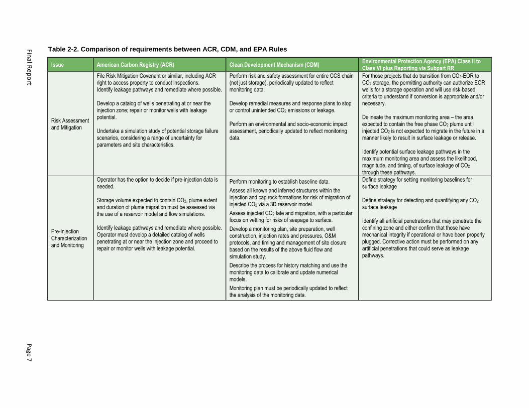
2.1.3 Monitoring, Reporting, and Verification Requirements
A number of documents provided guidance on MRV requirements that a CO2-EOR project has to satisfy
to qualify as storage (Table 2-2). American Carbon Registry protocols and U.S. EPA Program Guidance
documents outline requirements as well as performance measures without prescribing technologies.
Accordingly, there is significant flexibility for the project proponent to fashion the project details and
submit for approval plans that describe how requirements will be met. Common themes on developing
MRV plans include: (1) monitoring requirements need to be site specific and risk weighted; (2) additional
baseline and post-injection data acquisition are required; and (3) the results of monitoring need to be
transparent.
CO2-EOR operations are mainly monitored to check that bottom-hole and reservoir pressures are being
maintained within the operational constraints, to track the movement of the CO2 injected, and to ensure
that the wells are complying with integrity standards – especially due to the potential for flow assurance
problems stemming from the corrosive nature of CO2 in pipelines and hydrate forming hazards.
Monitoring and surveillance for these objectives are usually implemented via gauges for
injection/production and pressure data, geochemical analysis of produced fluids, and well logs and/or
downhole sensors that measure tracer concentration, fluid saturations, resistivity and casing integrity.
Seismic surveys have also been used to monitor for CO2 plume movement. Additional monitoring
requirements for storage include demonstrating integrity of the producing reservoir, verification of the
quantity of stored CO2, wellbore integrity monitoring, plume pathways monitoring, near-surface
monitoring, and surface monitoring (CSLF, 2013).
Wolaver et al. (2013) describes the major items, processes and properties at varying depth intervals
(surface, intermediate and injection zone) for depleted oil and gas fields as a useful means of anticipating
project monitoring requirements. For developed sites such as depleted oil fields, monitoring is centered
around high well density and old wells providing leakage pathways, out-of-pattern migration of CO2, and
undetected damage to geologic seal quality as a result of development.
While the same monitoring technologies applicable for CO2-EOR are applicable to storage, more formal
reporting will be required, including development of a MRV Plan (ACR, 2015; U.S. EPA, 2010). A
significant difference between CO2-EOR and CO2-EOR storage is the post-injection long-term monitoring
requirement for CO2-EOR storage. While the ACR suggests a post-injection monitoring period of 5 years
for CO2-EOR storage projects, the clean development mechanism (CDM) requirements suggest a post-
injection monitoring period of 20 years. While the U.S. EPA does not have a default minimum requirement
for CO2-EOR storage, the U.S. EPA post-injection monitoring requirements for geological storage only is
50 years by default– but this time period can be shortened per the discretion of the U.S. EPA Director. A
common method for evaluating leakage is subsurface pressure monitoring and evaluation of changes in
pressure. Operators of CO2-EOR storage projects need to be aware and be proactive about post-injection
and site closure requirements. MRV Plans can help show safe and non-hazardous conditions,
maintaining trust of the public in the region.
2.1.4 Other Requirements
The International Organization for Standardization (ISO) is in the process of developing standards for
capture, transport, and storage within Technical Committee 265: Carbon Dioxide Capture, Transportation,
and Geological Storage. Storage standards are being developed for CCS and CO2-EOR-Storage. CO2-
EOR-Storage was split from CCS in-part, due to the inherent differences in the level of understanding on
the hydrocarbon production reservoir as compared to a CCS storage unit. The separate standards also
provide an opportunity to develop accounting schemes that reflect differences in site operations; injection
Final R
epo
rt
Page 7
Table 2-2. Comparison of requirements between ACR, CDM, and EPA Rules
Issue American Carbon Registry (ACR) Clean Development Mechanism (CDM) Environmental Protection Agency (EPA) Class II to Class VI plus Reporting via Subpart RR
Risk Assessment and Mitigation
File Risk Mitigation Covenant or similar, including ACR right to access property to conduct inspections. Identify leakage pathways and remediate where possible. Develop a catalog of wells penetrating at or near the injection zone; repair or monitor wells with leakage potential. Undertake a simulation study of potential storage failure scenarios, considering a range of uncertainty for parameters and site characteristics.
Perform risk and safety assessment for entire CCS chain (not just storage), periodically updated to reflect monitoring data. Develop remedial measures and response plans to stop or control unintended CO2 emissions or leakage. Perform an environmental and socio-economic impact assessment, periodically updated to reflect monitoring data.
For those projects that do transition from CO2-EOR to CO2 storage, the permitting authority can authorize EOR wells for a storage operation and will use risk-based criteria to understand if conversion is appropriate and/or necessary. Delineate the maximum monitoring area – the area expected to contain the free phase CO2 plume until injected CO2 is not expected to migrate in the future in a manner likely to result in surface leakage or release. Identify potential surface leakage pathways in the maximum monitoring area and assess the likelihood, magnitude, and timing, of surface leakage of CO2 through these pathways.
Pre-Injection Characterization and Monitoring
Operator has the option to decide if pre-injection data is needed. Storage volume expected to contain CO2, plume extent and duration of plume migration must be assessed via the use of a reservoir model and flow simulations. Identify leakage pathways and remediate where possible. Operator must develop a detailed catalog of wells penetrating at or near the injection zone and proceed to repair or monitor wells with leakage potential.
Perform monitoring to establish baseline data.
Assess all known and inferred structures within the injection and cap rock formations for risk of migration of injected CO2 via a 3D reservoir model.
Assess injected CO2 fate and migration, with a particular focus on vetting for risks of seepage to surface.
Develop a monitoring plan, site preparation, well construction, injection rates and pressures, O&M protocols, and timing and management of site closure based on the results of the above fluid flow and simulation study.
Describe the process for history matching and use the monitoring data to calibrate and update numerical models.
Monitoring plan must be periodically updated to reflect the analysis of the monitoring data.
Define strategy for setting monitoring baselines for surface leakage Define strategy for detecting and quantifying any CO2
surface leakage Identify all artificial penetrations that may penetrate the confining zone and either confirm that those have mechanical integrity if operational or have been properly plugged. Corrective action must be performed on any artificial penetrations that could serve as leakage pathways.
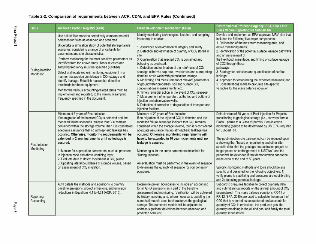
Table 2-2. Comparison of requirements between ACR, CDM, and EPA Rules (Continued)
Fina R
ep
ort
P
age 8
Issue American Carbon Registry (ACR) Clean Development Mechanism (CDM) Environmental Protection Agency (EPA) Class II to Class VI plus Reporting via Subpart RR
During-Injection Monitoring
Use a fluid flow model to periodically compare material balances for fluids as observed and predicted.
Undertake a simulation study of potential storage failure scenarios, considering a range of uncertainty for parameters and site characteristics.
Perform monitoring for the most sensitive parameters as identified from the above study. Tools selected and sampling frequency must be specified (justified).
Select and locate (other) monitoring equipment in a manner that provide confidence in CO2 storage and identify leakage. Establish reasonable detection thresholds for these equipment.
Monitor the various accounting-related terms must be implemented and reported, to the minimum sampling frequency specified in the document.
Identify monitoring technologies, location, and sampling frequency to enable: 1. Assurance of environmental integrity and safety. 2. Detection and estimation of quantity of CO2 stored in site. 3. Confirmation that injected CO2 is contained and behaving as predicted. 4. Detection and estimation of the rate/mass of CO2 seepage either via cap rock, overburden and surrounding domains or via wells with potential for leakage. 5. Monitoring and measurement of relevant parameters of groundwater properties, soil and surface CO2 concentrations measurements, etc. 6. Timely remedial action in the event of CO2 seepage. 7. Measurement of temperature at the top and bottom of injection and observation wells. 8. Detection of corrosion or degradation of transport and injection facilities.
Develop and implement an EPA-approved MRV plan that includes the following five major components: 1. Delineation of the maximum monitoring area, and active monitoring areas; 2. Identification of the potential surface leakage pathways and an assessment of the likelihood, magnitude, and timing of surface leakage of CO2 through these pathways; 3. Strategy for detection and quantification of surface leakage; 4. Approach for establishing the expected baselines; and 5. Considerations made to calculate site-specific variables for the mass balance equation.
Post-Injection Monitoring
Minimum of 5 years of Post-Injection. If no migration of the injected CO2 is detected and the modelled failure scenarios indicate that CO2 remains contained within the storage volume, then it is considered adequate assurance that no atmospheric leakage has occurred. Otherwise, monitoring requirements will be extended in 2 year increments until no leakage is assured. 1. Monitor for appropriate parameters, such as pressure, in injection zone and above confining layer. 2. Evaluate data to detect movement in CO2 plume. 3. Updating lateral boundaries of storage volume, based on assessment of CO2 migration.
Minimum of 20 years of Post-Injection. If no migration of the injected CO2 is detected and the modelled failure scenarios indicate that CO2 remains contained within the storage volume, then it is considered adequate assurance that no atmospheric leakage has occurred. Otherwise, monitoring requirements will have to be extended in 10 year increments until no leakage is assured. Monitoring is for the same parameters described for “During Injection”. An evaluation must be performed in the event of seepage to determine the quantity of seepage for compensation purposes.
Default value of 50 years of Post-Injection for Projects transitioning to geological storage (i.e., converts from a Class II permit to a Class VI permit). Post-injection monitoring (period to be determined by US EPA) required for Subpart RR. The post-injection site care period can be reduced upon a showing that "based on monitoring and other site-specific data, that the geologic sequestration project no longer poses an endangerment to USDWs," and the period will be extended if that demonstration cannot be made even at the end of 50 years. Specific monitoring methods and tools should be site specific and designed for the following objectives: 1) verify plume is stabilizing and pressures are equilibrating and 2) detecting potential leakage
Reporting/ Accounting
ACR details the methods and equations to quantify baseline emissions, project emissions, and emission reductions in Equations 4.1 to 4.21 (ACR, 2015).
Determine project boundaries to include an accounting for all GHG emissions as a part of the baseline assessment and monitoring. Verification will be achieved by history matching and, where necessary, updating the numerical models used to characterize the geological storage. The numerical models will be adjusted to address significant deviations between observed and predicted behavior.
Subpart RR requires facilities to collect quarterly data and submit annual reports on the annual amount of CO2 sequestered. The mass balance equations RR-11 or RR-12 (EPA, 2010) are used to calculate the amount of CO2 that is reported as sequestered and accounts for quantity of CO2 in emissions, the produced gas, the quantity remaining in the oil and gas, and finally the total quantity sequestered.
Final Report Page 9
only for CCS and injection and production for CO2-EOR-Storage. The CO2-EOR-Storage standard is
several years from completion.
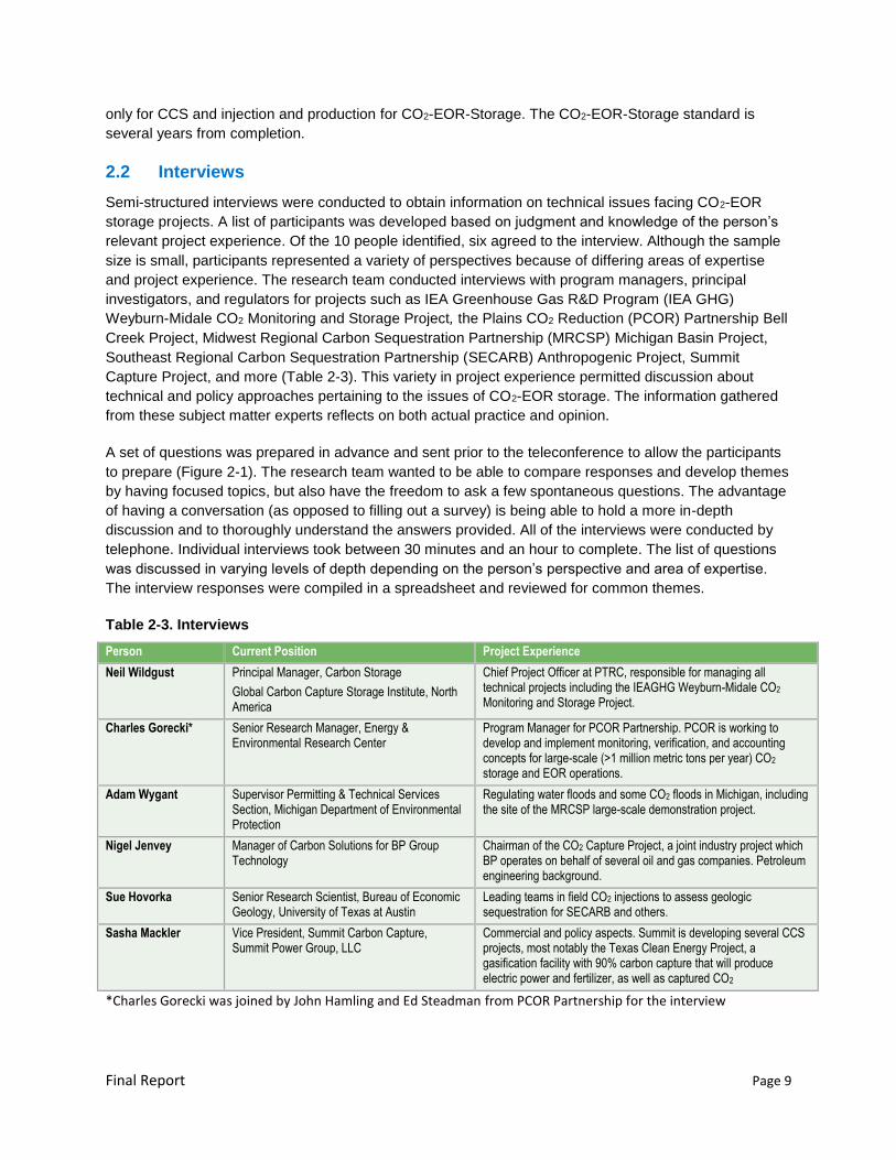
2.2 Interviews
Semi-structured interviews were conducted to obtain information on technical issues facing CO2-EOR
storage projects. A list of participants was developed based on judgment and knowledge of the person’s
relevant project experience. Of the 10 people identified, six agreed to the interview. Although the sample
size is small, participants represented a variety of perspectives because of differing areas of expertise
and project experience. The research team conducted interviews with program managers, principal
investigators, and regulators for projects such as IEA Greenhouse Gas R&D Program (IEA GHG)
Weyburn-Midale CO2 Monitoring and Storage Project, the Plains CO2 Reduction (PCOR) Partnership Bell
Creek Project, Midwest Regional Carbon Sequestration Partnership (MRCSP) Michigan Basin Project,
Southeast Regional Carbon Sequestration Partnership (SECARB) Anthropogenic Project, Summit
Capture Project, and more (Table 2-3). This variety in project experience permitted discussion about
technical and policy approaches pertaining to the issues of CO2-EOR storage. The information gathered
from these subject matter experts reflects on both actual practice and opinion.
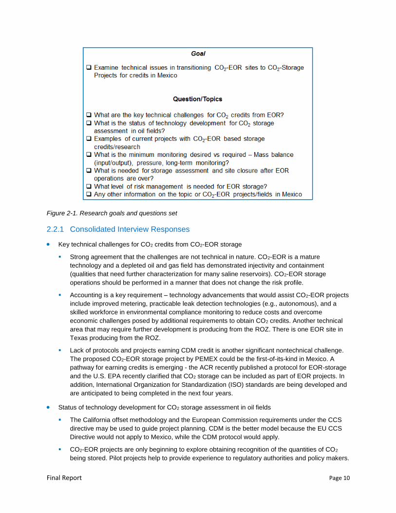
A set of questions was prepared in advance and sent prior to the teleconference to allow the participants
to prepare (Figure 2-1). The research team wanted to be able to compare responses and develop themes
by having focused topics, but also have the freedom to ask a few spontaneous questions. The advantage
of having a conversation (as opposed to filling out a survey) is being able to hold a more in-depth
discussion and to thoroughly understand the answers provided. All of the interviews were conducted by
telephone. Individual interviews took between 30 minutes and an hour to complete. The list of questions
was discussed in varying levels of depth depending on the person’s perspective and area of expertise.
The interview responses were compiled in a spreadsheet and reviewed for common themes.
Table 2-3. Interviews
Person Current Position Project Experience
Neil Wildgust Principal Manager, Carbon Storage
Global Carbon Capture Storage Institute, North America
Chief Project Officer at PTRC, responsible for managing all technical projects including the IEAGHG Weyburn-Midale CO2 Monitoring and Storage Project.
Charles Gorecki* Senior Research Manager, Energy & Environmental Research Center
Program Manager for PCOR Partnership. PCOR is working to develop and implement monitoring, verification, and accounting concepts for large-scale (>1 million metric tons per year) CO2 storage and EOR operations.
Adam Wygant Supervisor Permitting & Technical Services Section, Michigan Department of Environmental Protection
Regulating water floods and some CO2 floods in Michigan, including the site of the MRCSP large-scale demonstration project.
Nigel Jenvey Manager of Carbon Solutions for BP Group Technology
Chairman of the CO2 Capture Project, a joint industry project which BP operates on behalf of several oil and gas companies. Petroleum engineering background.
Sue Hovorka Senior Research Scientist, Bureau of Economic Geology, University of Texas at Austin
Leading teams in field CO2 injections to assess geologic sequestration for SECARB and others.
Sasha Mackler
Vice President, Summit Carbon Capture, Summit Power Group, LLC
Commercial and policy aspects. Summit is developing several CCS projects, most notably the Texas Clean Energy Project, a gasification facility with 90% carbon capture that will produce electric power and fertilizer, as well as captured CO2
*Charles Gorecki was joined by John Hamling and Ed Steadman from PCOR Partnership for the interview
Final Report Page 10
Figure 2-1. Research goals and questions set
2.2.1 Consolidated Interview Responses
Key technical challenges for CO2 credits from CO2-EOR storage
Strong agreement that the challenges are not technical in nature. CO2-EOR is a mature
technology and a depleted oil and gas field has demonstrated injectivity and containment
(qualities that need further characterization for many saline reservoirs). CO2-EOR storage
operations should be performed in a manner that does not change the risk profile.
Accounting is a key requirement – technology advancements that would assist CO2-EOR projects
include improved metering, practicable leak detection technologies (e.g., autonomous), and a
skilled workforce in environmental compliance monitoring to reduce costs and overcome
economic challenges posed by additional requirements to obtain CO2 credits. Another technical
area that may require further development is producing from the ROZ. There is one EOR site in
Texas producing from the ROZ.
Lack of protocols and projects earning CDM credit is another significant nontechnical challenge.
The proposed CO2-EOR storage project by PEMEX could be the first-of-its-kind in Mexico. A
pathway for earning credits is emerging - the ACR recently published a protocol for EOR-storage
and the U.S. EPA recently clarified that CO2 storage can be included as part of EOR projects. In
addition, International Organization for Standardization (ISO) standards are being developed and
are anticipated to being completed in the next four years.
Status of technology development for CO2 storage assessment in oil fields
The California offset methodology and the European Commission requirements under the CCS
directive may be used to guide project planning. CDM is the better model because the EU CCS
Directive would not apply to Mexico, while the CDM protocol would apply.
CO2-EOR projects are only beginning to explore obtaining recognition of the quantities of CO2
being stored. Pilot projects help to provide experience to regulatory authorities and policy makers.
Final Report Page 11
European Directive requirements include accounting for energy consumption for operations
including extraction, compression, and heating for EOR because these added steps make EOR
more energy intensive.
Operators should consider skipping the water flooding step, particularly in lower permeability
formations (1 to 10 mD range).
Examples of current projects with CO2-EOR based storage credits/research
None of the people interviewed could offer an example of a current project receiving storage
credits
The U.S. and Canada are the key players in CO2-EOR. Brazil is also a player. China is rapidly
accelerating its progress toward CO2-EOR, with the prime motivation of increasing oil recovery.
In the U.S., researchers have completed and/or are completing a number of large scale
demonstration projects to examine issues related to CO2-EOR storage. These large-scale
projects are testing monitoring technologies and modeling techniques to assess their
effectiveness for use with CO2-EOR storage.
In Canada, the Weyburn-Midale project is a well-known example of a CO2-EOR based storage
research project. The extent of monitoring required for a commercial CO2-EOR storage project
would be a smaller subset than performed for the Weyburn-Midale research project.
Lessons learned from these projects include:
‒ Three-dimensional (3D) seismic is useful for characterization. When conducted over time,
time-lapse (4D) seismic may be powerful tool for monitoring CO2 migration. However, the
cost of repeat events is a key consideration. Furthermore, seismic may not be applicable in
many geologic settings.
‒ Passive seismic/microseismic used on downhole array offered dual benefits – it produced
useful data to learn about the reservoir and provided stakeholder assurance.
‒ Consider deploying lower cost monitoring techniques first followed by higher cost
technologies. For example, using pulsed neutron capture (PNC) logs first and performing
seismic second, to parse out CO2 saturation/pressure.
- On the environmental side, baseline soil gas monitoring/near surface monitoring proved to be
valuable for establishing a frame-of-reference when the project faced a leakage allegation at
the Weyburn-Midale Project. Near surface monitoring in combination with analysis of isotopic
signatures helped to differentiate normally occurring CO2 from potential leakage.
‒ Satellite based technologies such as InSAR (interferometric satellite radar) could be cost-
effective, but the feasibility of this technology is site specific.
In the U.S., obtaining tax credits is an available incentive for CO2-EOR projects with incidental
storage and this mechanism is being pursued, particularly in Texas.
What is the minimum monitoring desired versus required – Mass balance (input/output) pressure,
long-term monitoring?
CO2-EOR storage projects require a different approach to monitoring compared to pure saline
projects. Because EOR is intensively engineered, only modest, if any, monitoring is required.
The minimum monitoring requirements include mass balance, pressure, and downhole
temperature.
Final Report Page 12
All but one person interviewed noted that well integrity was the most important item to monitor.
Monitoring requirements to receive credits are not known. In the U.S., demonstrating storage of
CO2 in EOR projects requires meeting both Underground Injection Control (UIC) permit
requirements and GHG reporting requirements. Exactly which requirements apply will depend on
the protocols under which credits are sought. For example, obtaining quantification of CO2
storage under EPA's GHG reporting regime requires reporting pursuant to subpart RR. (No EOR
projects have opted into subpart RR since the rule was established.)
The topic yielded a variety in the opinions on the importance of environmental compliance
monitoring from “not required/don’t do it” to “required/do it”. One commonality was that
appropriate environmental compliance monitoring technologies could include those meaningful
for public perception, even if the technology is not applicable to reservoir performance.
Modeling will likely be required - something more sophisticated than mass balance to
demonstrate an understanding of the subsurface.
‒ History matching is a great tool and augments mass balance. Tune simulations to monitoring
data to gain better confidence in model results.
‒ Understanding fracture pressure of caprock is required if there is a need to go above
discovery pressure to get to minimum miscible pressure. Microseismic monitoring may also
be helpful in this case.
The burden of monitoring is in the reporting. Industry is already doing most of the monitoring and
modeling that could be used to demonstrate storage. However, industry may be inclined to avoid
the public disclosures required to get credits and demonstrate storage because of concerns
regarding privacy and loss of competitive advantage. These concerns will need to be addressed.
What is needed for storage assessment and site closure after EOR operations are over?
Nearly all interviewed raised the concern about the stranded oil left behind and the implications
for site closure. The stranded oil may have a future value due to new technologies or higher oil
prices. In such situations, the field owner may wish to reenter the fields for production, leading to
potential loss of storage CO2. Handling of credits in such situations is not clear at this point.
A risk-based approach is required. If the pressure is stable and the wells are built and abandoned
properly, the site is low risk even after the engineering controls are removed. On the other hand,
if the operator goes above discovery pressure (but below fracture pressure), the risk profile
changes. Additional characterization, monitoring, and modeling may be necessary because the
operator may need to rely on predictive modeling rather than historical data.
Additional leakage monitoring and modeling to demonstrate permanent storage are manageable
tasks within a bounded frame of time. A reasonable post-injection monitoring step may be
necessary to encourage acceptance of CO2-EOR.
What level of risk management is needed for EOR storage?
Site specific
Depends on the reservoir type. Closed reservoirs such as reefs are straight forward. An open
reservoir would be more complicated if there was a possibility the CO2 or other fluids could go
beyond project boundaries to a leakage pathway.
Pure saline reservoirs are much different because they are likely to be larger and do not have
proven containment until additional characterization is conducted. CO2-EOR storage projects are
Final Report Page 13
likely to be smaller in size and, if the reservoir remains at or below discovery pressure, the risk
profile has not changed compared to an EOR-only project.
Wellbore integrity is the biggest issue – an operator should monitor casing performance, which
can degrade rapidly. Options include mechanical integrity tests (MITs), sustained casing
pressure, and annulus pressure monitoring.
Any other information on the topic or CO2-EOR projects/fields in Mexico
None offered
2.3 Region-Specific Considerations
Regional information pertaining to the Isthmus Saline Basin, where the Cinco Presidentes Oilfield is
located, was gathered using publicly available literature specific to CO2-EOR assessments in Mexican
oilfields. A brief discussion of regional geology and CO2 sources near Cinco Presidentes follows.
2.3.1 Regional Geologic Information
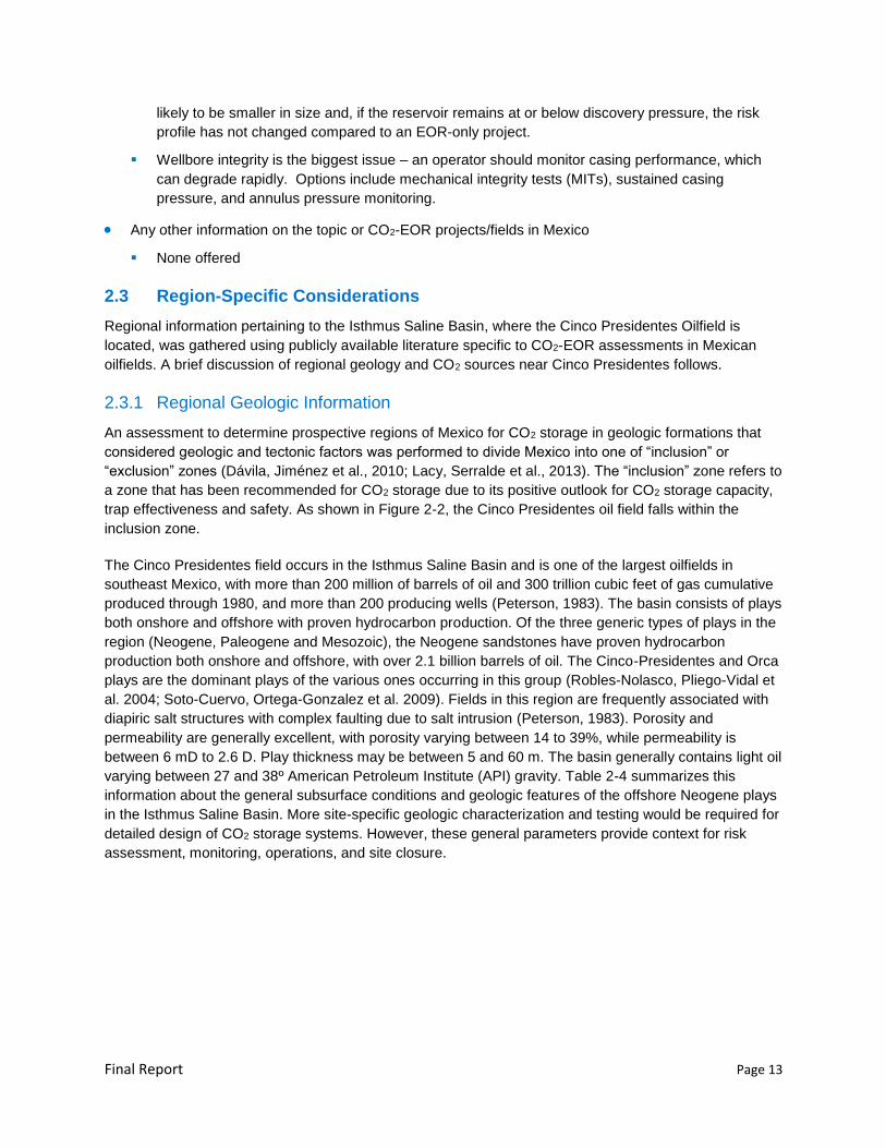
An assessment to determine prospective regions of Mexico for CO2 storage in geologic formations that
considered geologic and tectonic factors was performed to divide Mexico into one of “inclusion” or
“exclusion” zones (Dávila, Jiménez et al., 2010; Lacy, Serralde et al., 2013). The “inclusion” zone refers to
a zone that has been recommended for CO2 storage due to its positive outlook for CO2 storage capacity,
trap effectiveness and safety. As shown in Figure 2-2, the Cinco Presidentes oil field falls within the
inclusion zone.
The Cinco Presidentes field occurs in the Isthmus Saline Basin and is one of the largest oilfields in
southeast Mexico, with more than 200 million of barrels of oil and 300 trillion cubic feet of gas cumulative
produced through 1980, and more than 200 producing wells (Peterson, 1983). The basin consists of plays
both onshore and offshore with proven hydrocarbon production. Of the three generic types of plays in the
region (Neogene, Paleogene and Mesozoic), the Neogene sandstones have proven hydrocarbon
production both onshore and offshore, with over 2.1 billion barrels of oil. The Cinco-Presidentes and Orca
plays are the dominant plays of the various ones occurring in this group (Robles-Nolasco, Pliego-Vidal et
al. 2004; Soto-Cuervo, Ortega-Gonzalez et al. 2009). Fields in this region are frequently associated with
diapiric salt structures with complex faulting due to salt intrusion (Peterson, 1983). Porosity and
permeability are generally excellent, with porosity varying between 14 to 39%, while permeability is
between 6 mD to 2.6 D. Play thickness may be between 5 and 60 m. The basin generally contains light oil
varying between 27 and 38º American Petroleum Institute (API) gravity. Table 2-4 summarizes this
information about the general subsurface conditions and geologic features of the offshore Neogene plays
in the Isthmus Saline Basin. More site-specific geologic characterization and testing would be required for
detailed design of CO2 storage systems. However, these general parameters provide context for risk
assessment, monitoring, operations, and site closure.
Final Report Page 14
Figure 2-2. Zones suitable for CO2 storage in green (top map) and the location of the Cinco Presidentes oilfield (bottom map) in Mexico (Lacy, Serralde et al. 2013)
Final Report Page 15
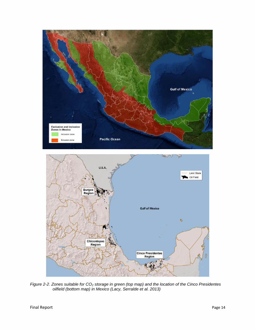
Table 2-4. General subsurface conditions and geologic features in Cinco Presidentes Region
Parameters Range
Play Types Early-Middle Pliocene (Cinco Presidentes Turbiditas
Play and Cinco Presidentes Barras Play)
Middle-Late Pliocene (Orca Turbiditas Play and Orca
Barras Play)
Depth 2500 meters
Thickness 5-60 meters in reservoirs
Lithology Miocene-Pliocene mix of marine and fluvial deltaic
turbidities (sandstone, siltstone, shale, salt)
Geologic
Structures
Complex mixture of compressive, extensive,
structures with salt intrusions
Trapping
Mechanisms
Mixture of anticlines, salt dome pinchouts, sealing
faults, lithologic traps
Porosity 14-39%
Temperature ~80 º C in reservoirs
Permeability 5 md – 2.6 d in reservoirs
Hydrocarbons Mix of oil (27-38º API), condensates, gas
2.3.2 Regional CO2 Sources
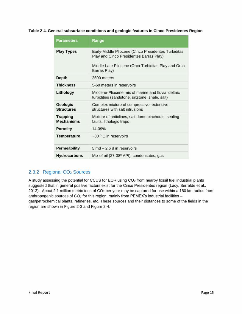
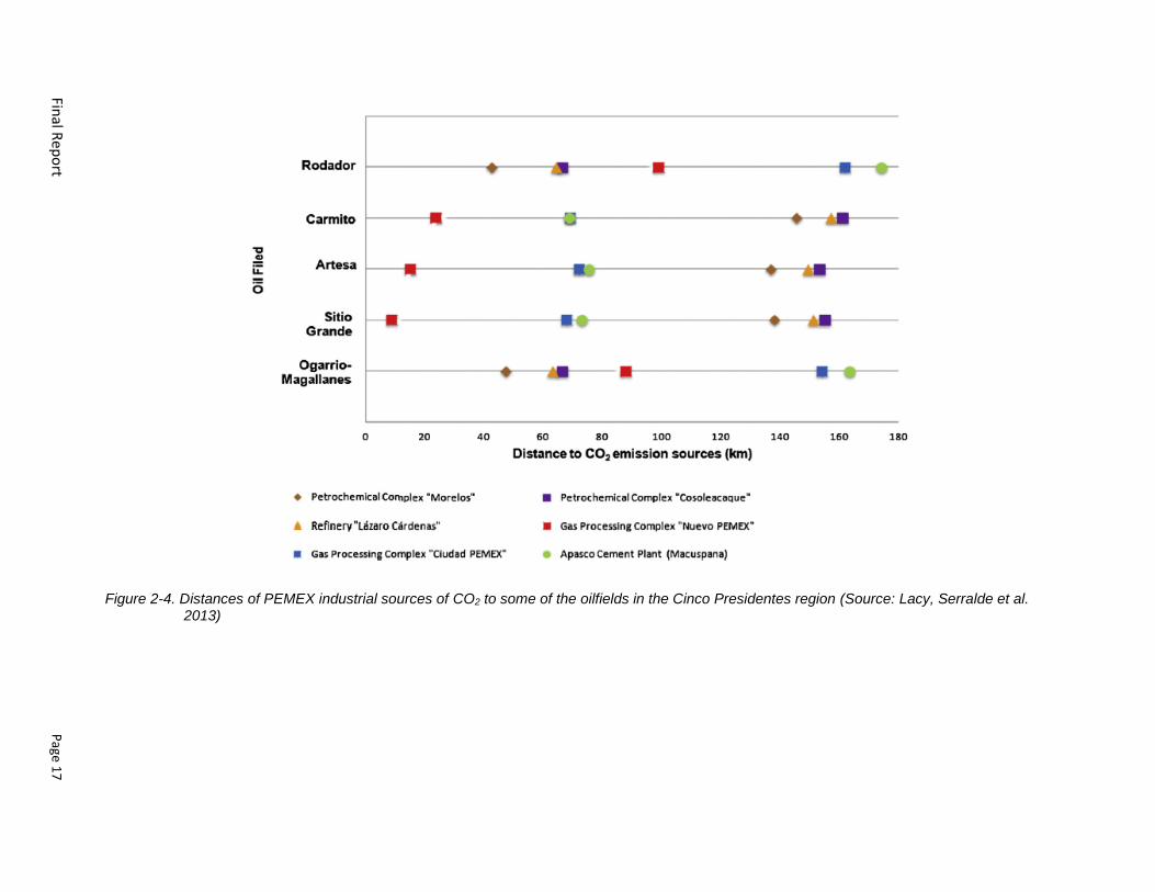
A study assessing the potential for CCUS for EOR using CO2 from nearby fossil fuel industrial plants
suggested that in general positive factors exist for the Cinco Presidentes region (Lacy, Serralde et al.,
2013). About 2.1 million metric tons of CO2 per year may be captured for use within a 180 km radius from
anthropogenic sources of CO2 for this region, mainly from PEMEX’s industrial facilities –
gas/petrochemical plants, refineries, etc. These sources and their distances to some of the fields in the
region are shown in Figure 2-3 and Figure 2-4.
Final R
epo
rt
Page 1
6
Figure 2-3. Major PEMEX industrial sources of CO2 (>0.5million metric tons/year) in Cinco Presidentes region (the area of interest) (Source: Lacy, Serralde et al., 2013)
Final R
epo
rt
Page 1
7
Figure 2-4. Distances of PEMEX industrial sources of CO2 to some of the oilfields in the Cinco Presidentes region (Source: Lacy, Serralde et al. 2013)

Final Report Page 18
2.4 Conclusions
The current view of CO2-EOR storage projects is that these types of projects are technically feasible and
eligible for CDM credits. However, significant economic and regulatory incentives and anthropogenic
sources of CO2 are pre-cursors for widespread deployment. The protocols for obtaining credits typically
outline requirements as performance measures without prescribing technologies. As a result, the project
proponent has significant flexibility to develop and submit risk-based plans using fit-for-purpose
methodologies that describe how requirements will be met. However, the first-of-a-kind nature of CO2-
EOR-storage projects could prove a hindrance, as could the absence of any provisions in protocols that
are specifically tailored to oil field operations. The developing ISO standards for CO2 capture,
transportation and storage, which will include incidental storage of anthropogenic CO2 in association with
EOR, promises to provide a better pathway to credits. In absence of prescriptive requirements in the near
term, EOR operators are advised to answer a series of questions when pursuing associated storage or
transitioning to storage without production:
What are the specific risks at this site?
What modeling tools would be useful?
How do I prove containment?
What baseline or other frame-of-reference data could be useful to collect?
How will I measure, monitor and verify the amount of CO2 stored?
What is the appropriate post-injection monitoring strategy to demonstrate that 99% of the CO2 within
the reservoir will be stored for at least 100 years?
What are the legal and regulatory issues for transitioning to storage without production?
The following section examines these issues in more detail.
Final Report Page 19
Chapter 3 Identification of Key Issues for CO2-EOR Storage Projects
The information collected during the literature search and expert interviews was compiled and
synthesized to highlight key issues for CO2-EOR storage projects with relevance to Mexico. This task
builds upon previous work and summarizes the options and challenges for CO2-EOR storage.
3.1 Risk Assessment Options
Risk assessment methods are used to characterize and catalog the safety attributes of storage sites
(WRI, 2008; Intergovernmental Panel on Climate Change [IPCC], 2005). The risk assessment process
often includes site screening, selection, and characterization of a geologic CO2 storage site to provide
guidance in CO2 storage system design, operation, and closure (Department of Energy National Energy
Technology Laboratory [DOE-NETL], 2011). Risk factors may be classified as both programmatic (related
to project progress and costs) and technical (related to the scientific and engineering integrity of the
storage system) (DOE-NETL, 2013). Because CO2 is a natural gas present throughout the environment,
CO2 storage risk analysis methods are often focused on leakage pathways rather than the quantitative
expression of risk as probability multiplied by consequence. Several risk analysis tools (qualitative and
quantitative) have been developed to evaluate CO2 storage sites, such as:
A Generic Features, Events and Processes (FEP) Database for the Assessment of Long-Term
Performance and Safety of the Geological Storage of CO2 (Savage et al., 2004) - Databases of FEPs
are tools to support the assessment of long-term safety and performance of geological CO2 storage.
The FEP database is divided into seven main classes, covering events as broad as neotectonics to
microscopic processes such as complexation of CO2 with heavy metals. This tool and supporting
details is available on-line at https://www.quintessa.org/case-studies/online-database-of-features-
events-and-processes-for-co2.html.
Certification Framework Based on Effective Trapping for Geologic Carbon Sequestration (Oldenburg
et al., 2009) - A simple framework for evaluating leakage risk for certifying operation and
decommissioning of geological CO2 storage sites
A System Model for Geologic Sequestration of Carbon Dioxide (Stauffer et al., 2009) - CO2 Predictive
Engineered Natural Systems (PENS) is a software tool that links together physics-based process-
level modules that describe the entire CO2 sequestration pathway, starting from capture at a power
plant and following CO2 through pipelines to the injection site and into the reservoir.
Risk analysis typically involves “brainstorming” sessions with subject-matter experts led by an
experienced risk management facilitator. The risk analysis is designed to address all phases of the
project, from well preparation, to characterization, injection, monitoring, and post-injection well closure.
Risk analysis also considers other activities, such as scenarios related to project management as well as
maintenance and workover activities.
In addition to risk analysis tools, studies have focused on specific processes such as CO2 migration
through boreholes and geologic pathways (Celia et al., 2004). Recently, DOE-NETL has led a National
Risk Assessment Partnership to quantify long-term risks at CO2 sequestration sites (Pawar et al., 2014).
Final Report Page 20
The risk assessment may take advantage of the geologic and production histories of depleted oil fields to
provide confidence in capacity, injectivity, model prediction, and long-term CO2 retention. Most depleted
fields have undergone significant site characterization as part of exploration and production. As a result,
there is an inherent confidence in the reservoir injectivity and effectiveness of the containment. In
contrast, saline reservoirs have not undergone characterization similar to the oil fields. Therefore,
additional sub-surface data collection through seismic surveys and drilling is required to demonstrate
capacity and retention capability. However, high well density for production may increase uncertainty
regarding long-term well-retention in depleted oil fields compared to CO2 storage in saline reservoirs. In
addition, factors such as the potential for damage to the confining layers during operation should be
evaluated during characterization.
3.1.1 Wellbore Integrity Analysis
Potential CO2 migration through existing oil and gas wells is considered a major risk factor for CO2
storage. Wellbore integrity is especially important for transitioning from CO2-EOR to CO2 storage because
oil fields typically have many legacy wellbores that penetrate the confining layers.
The potential for wellbore leakage is identified during the risk assessment. Depending on the outcome of
the risk assessment, a more detailed review on the status of wells in the area, or wellbore integrity
analysis, may be required. Data such as well location, construction, depth, rock formations penetrated,
plugging methods, and status are compiled on wells near the field location to determine if the wells may
be pathways for CO2 migration.
Well casing may be subject to corrosion in CO2 environments in the subsurface. This is especially
relevant to CO2-EOR fields that alternate water and CO2 injection. Well casing is used in oil and gas wells
to stabilize the borehole, prevent unconsolidated material from entering the borehole, reduce corrosion,
and protect underground aquifers. Casing and tubing are classified by API type of steel (H-Q) and
minimum yield strength (40,000 to 125,000+ pounds per square inch [psi]). In general, higher grades of
steel are designed for deeper wells, higher temperatures, higher pressures, and corrosion resistance.
Many grades of steel are designed to be more ductile to prevent brittle failure from hydrogen sulfide (H2S)
gas.
In relation to CO2 storage, existing oil and gas well casing may be affected if it comes in contact with CO2
or CO2/water mixture in the subsurface. Pure CO2 is referred to as “sweet gas” when encountered in the
oil and gas industry and can cause pitting and pinhole leaks in casing, joints, tubing, and packers. API
grade of L-80 or greater is recommended for these applications. Other options for corrosion resistance
include alloy plating (nickel, chrome, etc.), polymer coatings, stainless steel, and fiberglass casing
(Popoola et al., 2013).
Table 3-1 summarizes casing/tubing materials for CO2 storage applications. These options are typically
more expensive and more difficult to handle in the field and are susceptible to damage due to scrapes,
nicks, and scratches. Many operators use common steel grades (J-55) with few problems as long as they
produce or inject relatively pure CO2. However, some EOR fields encounter significant corrosion when
injecting water alternating CO2 gas. Tubular design should take into account reservoir conditions and the
composition of and conditions of the fluids being injected and produced. Corrosion modeling can be
incorporated into tubular design to ensure the carbonic acid, high chlorides, and H2S are accounted for
when selecting metal grades and alloys. Dry CO2 is generally not considered to be corrosive, allowing
the use of mild steels (e.g. J and K grades). H2S may require special grades or metallurgies (e.g. L80 as
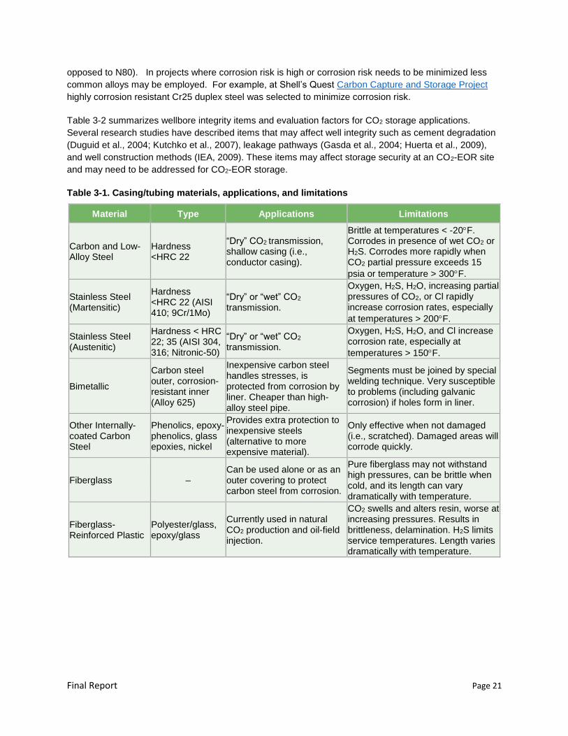
Final Report Page 21
opposed to N80). In projects where corrosion risk is high or corrosion risk needs to be minimized less
common alloys may be employed. For example, at Shell’s Quest Carbon Capture and Storage Project
highly corrosion resistant Cr25 duplex steel was selected to minimize corrosion risk.
Table 3-2 summarizes wellbore integrity items and evaluation factors for CO2 storage applications.
Several research studies have described items that may affect well integrity such as cement degradation
(Duguid et al., 2004; Kutchko et al., 2007), leakage pathways (Gasda et al., 2004; Huerta et al., 2009),
and well construction methods (IEA, 2009). These items may affect storage security at an CO2-EOR site
and may need to be addressed for CO2-EOR storage.
Table 3-1. Casing/tubing materials, applications, and limitations
Material Type Applications Limitations
Carbon and Low-Alloy Steel
Hardness <HRC 22
“Dry” CO2 transmission, shallow casing (i.e., conductor casing).
Brittle at temperatures < -20F. Corrodes in presence of wet CO2 or H2S. Corrodes more rapidly when CO2 partial pressure exceeds 15
psia or temperature > 300F.
Stainless Steel (Martensitic)
Hardness <HRC 22 (AISI 410; 9Cr/1Mo)
“Dry” or “wet” CO2
transmission.
Oxygen, H2S, H2O, increasing partial pressures of CO2, or Cl rapidly increase corrosion rates, especially
at temperatures > 200F.
Stainless Steel (Austenitic)
Hardness < HRC 22; 35 (AISI 304, 316; Nitronic-50)
“Dry” or “wet” CO2
transmission.
Oxygen, H2S, H2O, and Cl increase corrosion rate, especially at
temperatures > 150F.
Bimetallic
Carbon steel outer, corrosion-resistant inner (Alloy 625)
Inexpensive carbon steel handles stresses, is protected from corrosion by liner. Cheaper than high-alloy steel pipe.
Segments must be joined by special welding technique. Very susceptible to problems (including galvanic corrosion) if holes form in liner.
Other Internally-coated Carbon Steel
Phenolics, epoxy-phenolics, glass epoxies, nickel
Provides extra protection to inexpensive steels (alternative to more expensive material).
Only effective when not damaged (i.e., scratched). Damaged areas will corrode quickly.
Fiberglass – Can be used alone or as an outer covering to protect carbon steel from corrosion.
Pure fiberglass may not withstand high pressures, can be brittle when cold, and its length can vary dramatically with temperature.
Fiberglass-Reinforced Plastic
Polyester/glass, epoxy/glass
Currently used in natural CO2 production and oil-field injection.
CO2 swells and alters resin, worse at increasing pressures. Results in brittleness, delamination. H2S limits service temperatures. Length varies dramatically with temperature.
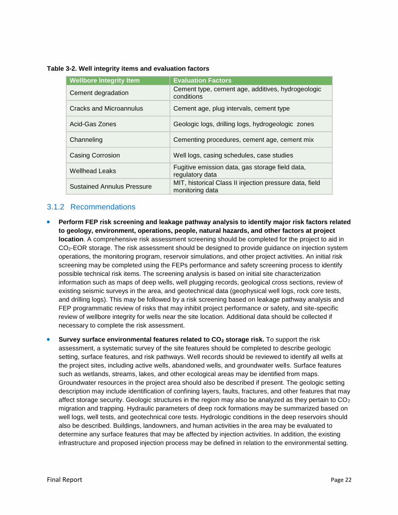
Final Report Page 22
Table 3-2. Well integrity items and evaluation factors
Wellbore Integrity Item Evaluation Factors
Cement degradation Cement type, cement age, additives, hydrogeologic conditions
Cracks and Microannulus Cement age, plug intervals, cement type
Acid-Gas Zones Geologic logs, drilling logs, hydrogeologic zones
Channeling Cementing procedures, cement age, cement mix
Casing Corrosion Well logs, casing schedules, case studies
Wellhead Leaks Fugitive emission data, gas storage field data, regulatory data
Sustained Annulus Pressure MIT, historical Class II injection pressure data, field monitoring data
3.1.2 Recommendations
Perform FEP risk screening and leakage pathway analysis to identify major risk factors related
to geology, environment, operations, people, natural hazards, and other factors at project
location. A comprehensive risk assessment screening should be completed for the project to aid in
CO2-EOR storage. The risk assessment should be designed to provide guidance on injection system
operations, the monitoring program, reservoir simulations, and other project activities. An initial risk
screening may be completed using the FEPs performance and safety screening process to identify
possible technical risk items. The screening analysis is based on initial site characterization
information such as maps of deep wells, well plugging records, geological cross sections, review of
existing seismic surveys in the area, and geotechnical data (geophysical well logs, rock core tests,
and drilling logs). This may be followed by a risk screening based on leakage pathway analysis and
FEP programmatic review of risks that may inhibit project performance or safety, and site-specific
review of wellbore integrity for wells near the site location. Additional data should be collected if
necessary to complete the risk assessment.
Survey surface environmental features related to CO2 storage risk. To support the risk
assessment, a systematic survey of the site features should be completed to describe geologic
setting, surface features, and risk pathways. Well records should be reviewed to identify all wells at
the project sites, including active wells, abandoned wells, and groundwater wells. Surface features
such as wetlands, streams, lakes, and other ecological areas may be identified from maps.
Groundwater resources in the project area should also be described if present. The geologic setting
description may include identification of confining layers, faults, fractures, and other features that may
affect storage security. Geologic structures in the region may also be analyzed as they pertain to CO2
migration and trapping. Hydraulic parameters of deep rock formations may be summarized based on
well logs, well tests, and geotechnical core tests. Hydrologic conditions in the deep reservoirs should
also be described. Buildings, landowners, and human activities in the area may be evaluated to
determine any surface features that may be affected by injection activities. In addition, the existing
infrastructure and proposed injection process may be defined in relation to the environmental setting.
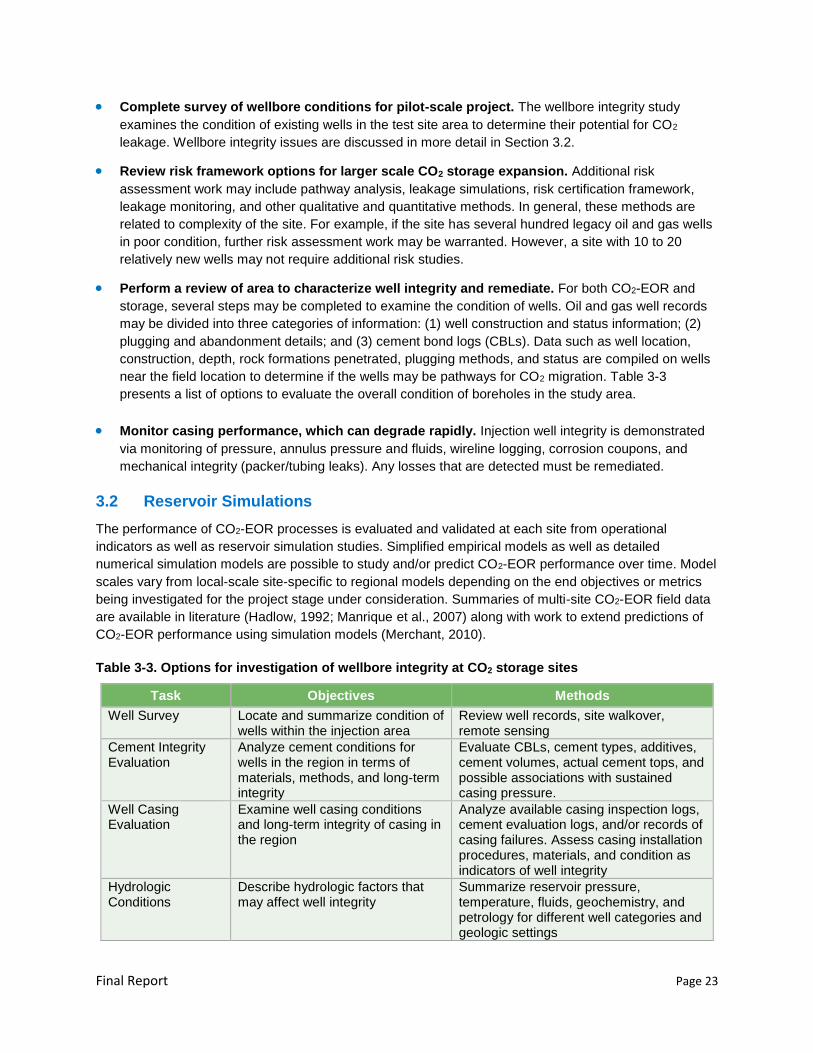
Final Report Page 23
Complete survey of wellbore conditions for pilot-scale project. The wellbore integrity study
examines the condition of existing wells in the test site area to determine their potential for CO2
leakage. Wellbore integrity issues are discussed in more detail in Section 3.2.
Review risk framework options for larger scale CO2 storage expansion. Additional risk
assessment work may include pathway analysis, leakage simulations, risk certification framework,
leakage monitoring, and other qualitative and quantitative methods. In general, these methods are
related to complexity of the site. For example, if the site has several hundred legacy oil and gas wells
in poor condition, further risk assessment work may be warranted. However, a site with 10 to 20
relatively new wells may not require additional risk studies.
Perform a review of area to characterize well integrity and remediate. For both CO2-EOR and
storage, several steps may be completed to examine the condition of wells. Oil and gas well records
may be divided into three categories of information: (1) well construction and status information; (2)
plugging and abandonment details; and (3) cement bond logs (CBLs). Data such as well location,
construction, depth, rock formations penetrated, plugging methods, and status are compiled on wells
near the field location to determine if the wells may be pathways for CO2 migration. Table 3-3
presents a list of options to evaluate the overall condition of boreholes in the study area.
Monitor casing performance, which can degrade rapidly. Injection well integrity is demonstrated
via monitoring of pressure, annulus pressure and fluids, wireline logging, corrosion coupons, and
mechanical integrity (packer/tubing leaks). Any losses that are detected must be remediated.
3.2 Reservoir Simulations
The performance of CO2-EOR processes is evaluated and validated at each site from operational
indicators as well as reservoir simulation studies. Simplified empirical models as well as detailed
numerical simulation models are possible to study and/or predict CO2-EOR performance over time. Model
scales vary from local-scale site-specific to regional models depending on the end objectives or metrics
being investigated for the project stage under consideration. Summaries of multi-site CO2-EOR field data
are available in literature (Hadlow, 1992; Manrique et al., 2007) along with work to extend predictions of
CO2-EOR performance using simulation models (Merchant, 2010).
Table 3-3. Options for investigation of wellbore integrity at CO2 storage sites
Task Objectives Methods
Well Survey Locate and summarize condition of wells within the injection area
Review well records, site walkover, remote sensing
Cement Integrity Evaluation
Analyze cement conditions for wells in the region in terms of materials, methods, and long-term integrity
Evaluate CBLs, cement types, additives, cement volumes, actual cement tops, and possible associations with sustained casing pressure.
Well Casing Evaluation
Examine well casing conditions and long-term integrity of casing in the region
Analyze available casing inspection logs, cement evaluation logs, and/or records of casing failures. Assess casing installation procedures, materials, and condition as indicators of well integrity
Hydrologic Conditions
Describe hydrologic factors that may affect well integrity
Summarize reservoir pressure, temperature, fluids, geochemistry, and petrology for different well categories and geologic settings

Final Report Page 24
The CCUS modeling approach is similar to traditional CO2-EOR studies, however, with a shift in the
optimization objectives from maximizing the oil production with minimal new CO2 intake, to maximizing
both oil production as well as CO2 retention. CCUS modeling objectives also include:
Modeling to complement monitoring program to aid regulatory compliance by analyzing fluid
dynamics in the system during pre-injection, injection and post-injection periods.
Evaluating technical and economic scenarios for decision-making on optimum completion and
operation strategies.
EOR fields being considered for geological storage have the benefit of extensive documentation of
historical production and recovery data. Screening of sites for new EOR fields is generally based upon a
consideration of geologic conditions (e.g., trap effectiveness, reservoir depth, etc.), fluid properties (e.g.,
minimum miscibility pressure) as well as other engineering parameters (e.g., sweep efficiency and
primary recovery efficiency). Existing EOR fields on the other hand, are screened based on demonstrated
CO2 injectivity and potential storage capacity. Additionally, reservoir models (Law et al., 2004), simplified
predictive models of CO2 performance (Azzolina et al., 2015) and related economic models (Bandza et
al., 2014) aid in the site screening and feasibility analysis of CCUS projects. As the selected site is
characterized and more detailed geologic and operational data are processed, detailed conceptual and
numerical models are developed to help investigate and predict CO2 interaction with the original fluids in
place during EOR and storage phases of the project. These analyses play critical roles during project
feasibility evaluation, design, implementation and post-injection closure phases.
Dai et al. (2013) performed simple sensitivity and uncertainty analysis using geostatistical Monte Carlo
simulations for CO2 storage potential in an EOR setting in Texas. Azzolina et al. (2015) analyzed WAG
CO2 floods to come up with useful statistical information to estimate CO2 storage in CO2 EOR operations
with various degrees of confidence. Detailed simulation work has documented the expected trapping
mechanisms for the injected CO2, evaluating the possible long-term fate of stored CO2 correlating to field
observations at the Weyburn project (Zhou et al., 2004).
Modeling studies have considered co-optimizing CO2 storage and EOR (Jessen et al., 2005; Ramirez
Salizar, 2009) by managing parameters such as well placement, sweeping the ROZs and injection ratios.
Reservoir simulation studies thus provide an efficient method to analyze the interplay of operational and
geologic controls in various scenarios to compare and optimize CCUS performance metrics such as CO2
utilization, oil recovery and CO2 stored (Ettehadtavakkol et al., 2014; Hill et al., 2013). Hybrid techniques
are being proposed as effective strategies to transition from traditional CO2-EOR to CO2 storage without
production (Jafari et al., 2013). Simple reservoir models have also been used to identify and evaluate
alternative CO2 production/injection strategies to increase CO2 storage in conjunction with EOR such as
injecting CO2 earlier, injecting CO2 longer by possibly skipping the waterflood stage prior to the CO2 flood
(ARI Inc. & Melzer Consulting, 2010).
Modeling is also extremely useful in tackling practical issues such as wellbore integrity analysis. A
number of modeling efforts have assessed the general range of impacts of well leakage on the basis of
semi-quantitative data available (e.g., Nordbotten et al., 2004). However, field-specific testing and
analysis would provide a more robust quantification of the frequency and magnitude of well leakage.
Detailed numerical simulations of CCUS in the reservoir of interest thus help investigate the interaction of
the injected CO2 with the original fluids in place and optimize oil production as well as CO2 retention
(Melzer, 2012) in the subsurface. Geomechanical integrity considerations drive operational limits such as
well injection rates and bottomhole pressure constraints. CO2 phase behavior complexity influences its
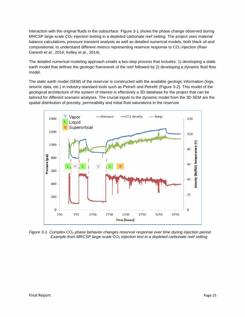
Final Report Page 25
interaction with the original fluids in the subsurface. Figure 3-1 shows the phase change observed during
MRCSP large-scale CO2 injection testing in a depleted carbonate reef setting. The project uses material
balance calculations, pressure transient analysis as well as detailed numerical models, both black oil and
compositional, to understand different metrics representing reservoir response to CO2 injection (Ravi
Ganesh et al., 2014; Kelley et al., 2014).
The detailed numerical modeling approach entails a two-step process that includes: 1) developing a static
earth model that defines the geologic framework of the reef followed by 2) developing a dynamic fluid flow
model.
The static earth model (SEM) of the reservoir is constructed with the available geologic information (logs,
seismic data, etc.) in industry-standard tools such as Petra® and Petrel® (Figure 3-2). This model of the
geological architecture of the system of interest is effectively a 3D database for the project that can be
tailored for different scenario analyses. The crucial inputs to the dynamic model from the 3D SEM are the
spatial distribution of porosity, permeability and initial fluid saturations in the reservoir.
Figure 3-1. Complex CO2 phase behavior changes reservoir response over time during injection period. Example from MRCSP large-scale CO2 injection test in a depleted carbonate reef setting
Final Report Page 26
Figure 3-2. Geologic model or SEM schematic flow diagram
The 3D SEM can then be imported into a dynamic reservoir simulation tool for fluid flow modeling using a
standard reservoir simulation workflow. Compositional and black-oil simulators such as industry-standard
Computer Modeling Group (CMG, 2010) and Eclipse (Schlumberger, 2012) are commonly used tools for
detailed numerical simulations. Information about fluid properties, rock compressibility, relative
permeability models, rock matrix properties, historical pressure and temperature conditions and well
details such as perforation depths and well schedules are utilized in reservoir simulations to effectively
assess CO2 utilization and geologic storage potential in the potential CCUS field (Figure 3-3). A calibrated
model of the reservoir is useful for predictive simulations of CCUS and other related sensitivity analyses.
The calibration is done by history-matching the primary (and secondary) production phase in the reservoir
model. This calibrated model would be followed by simulation of CO2 injection to better understand the
field-scale processes involved in the interaction of CO2 with the oil, hydrocarbon gas and water in place.
History-matched
reservoir model for predicting CO2 storage performance
PVT (Pressure, Volume,
Temperature) modeling
Geologic conceptual model to characterize reservoir
Field historical information:
Operational + Well details
Rock-fluid properties
Figure 3-3. Dynamic modeling inputs consideration for evaluation of CO2-EOR field performance and geologic storage potential
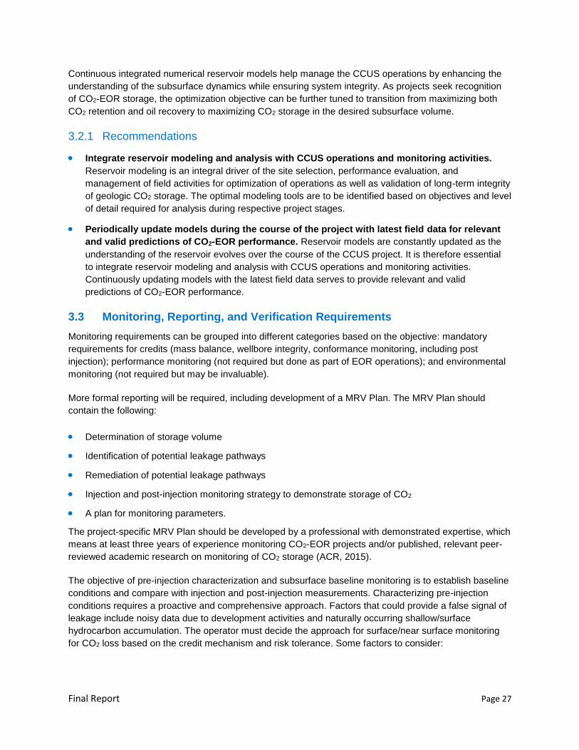
Final Report Page 27
Continuous integrated numerical reservoir models help manage the CCUS operations by enhancing the
understanding of the subsurface dynamics while ensuring system integrity. As projects seek recognition
of CO2-EOR storage, the optimization objective can be further tuned to transition from maximizing both
CO2 retention and oil recovery to maximizing CO2 storage in the desired subsurface volume.
3.2.1 Recommendations
Integrate reservoir modeling and analysis with CCUS operations and monitoring activities.
Reservoir modeling is an integral driver of the site selection, performance evaluation, and
management of field activities for optimization of operations as well as validation of long-term integrity
of geologic CO2 storage. The optimal modeling tools are to be identified based on objectives and level
of detail required for analysis during respective project stages.
Periodically update models during the course of the project with latest field data for relevant
and valid predictions of CO2-EOR performance. Reservoir models are constantly updated as the
understanding of the reservoir evolves over the course of the CCUS project. It is therefore essential
to integrate reservoir modeling and analysis with CCUS operations and monitoring activities.
Continuously updating models with the latest field data serves to provide relevant and valid
predictions of CO2-EOR performance.
3.3 Monitoring, Reporting, and Verification Requirements
Monitoring requirements can be grouped into different categories based on the objective: mandatory
requirements for credits (mass balance, wellbore integrity, conformance monitoring, including post
injection); performance monitoring (not required but done as part of EOR operations); and environmental
monitoring (not required but may be invaluable).
More formal reporting will be required, including development of a MRV Plan. The MRV Plan should
contain the following:
Determination of storage volume
Identification of potential leakage pathways
Remediation of potential leakage pathways
Injection and post-injection monitoring strategy to demonstrate storage of CO2
A plan for monitoring parameters.
The project-specific MRV Plan should be developed by a professional with demonstrated expertise, which
means at least three years of experience monitoring CO2-EOR projects and/or published, relevant peer-
reviewed academic research on monitoring of CO2 storage (ACR, 2015).
The objective of pre-injection characterization and subsurface baseline monitoring is to establish baseline
conditions and compare with injection and post-injection measurements. Characterizing pre-injection
conditions requires a proactive and comprehensive approach. Factors that could provide a false signal of
leakage include noisy data due to development activities and naturally occurring shallow/surface
hydrocarbon accumulation. The operator must decide the approach for surface/near surface monitoring
for CO2 loss based on the credit mechanism and risk tolerance. Some factors to consider:

Final Report Page 28
Reservoir type – open or closed
Past experience proving lack of leakage pathways
Extent of engineering controls
Availably of cost effective monitoring technology cable of detecting leakage
Regulatory perception
Public perception
Views on monitoring requirements vary, but there are three common themes: (1) monitoring activities are
site specific and risk weighted; (2) monitoring activities for CO2-EOR storage projects may need additional
baseline and post-injection data acquisition; and (3) monitoring activities need to be transparent and
subject to independent review.
A detailed site characterization is conducted to identify potential leakage pathways (Figure 3-4). Even for
a site with demonstrated containment, assessing for leakage pathways is an important part of developing
a monitoring plan. Conduits for CO2 leaks include CO2 injection wells, oil or gas production wells,
monitoring wells, abandoned wells, and faults and fractures. Geomechanical effects and well leakage are
the main technical issues associated with site selection for projects combining CO2-EOR with permanent
storage. Operations performed on the reservoir during primary and secondary recovery may have
geomechanically altered the reservoir by creation of new migration pathways and older legacy wells are
risk factors by offering a potential pathway for CO2 to migrate upwards. Near surface monitoring that can
discriminate a leakage signal from background concentrations and that can account for the noise
generated by previous site use are among the recommended strategies for CO2-EOR sites that are
applicable to storage (Wolaver et al., 2013).
The ACR Protocol offers the following guidance: “Depending on site-specific conditions, the Project
Proponent shall determine whether the monitoring approach would benefit from establishing pre-injection
levels. If deemed beneficial, these measurements shall be done for a period of times that allows for the
collection of data that are representative of site conditions prior to the initiation of injection. On-going
research on pre-injection monitoring techniques and approaches can be used as a valuable resource to
develop a project-specific monitoring plan. Innovative strategies to determine sources of groundwater
contamination in the absence of pre-injection data, which include the use of stable carbon isotopic
signatures, noble gases, and other metrics like hydrogen carbonate can be adapted for brownfields sites.
The results of ongoing research on soil monitoring can provide data to determine its value in a pre-
injection monitoring approach.” (ACR, 2015)
3.3.1 Recommendations
Develop a strategy for detecting and quantifying any CO2 surface leakage and to establish a
“baseline” for comparison. This could include near-surface, surface and atmospheric monitoring,
performed in stages and triggered upon leakage being detected via subsurface monitoring. In
addition, there are approaches to detect CO2 surface leakages from air and space.
Develop a MRV plan to help proactively manage project risks. Since the monitoring program for
any CCUS project is derived from risk assessment; the monitoring program should form a ‘tiered’
approach based on the risks identified (see Section 3.8 for further discussion). Project performance-
based measures constituting primary requirements would be reservoir zone monitoring to intensively
track the pressure, temperature and CO2 plume. Leakage detection and management can be

Final Report Page 29
implemented by monitoring above-zone and possibly less intensive surface monitoring. Table 3-4
summarizes the relevant monitoring zones. Table 3-5 summarizes monitoring options applicable for
CO2 storage sites.
3.4 Accounting
The amount of CO2 that can be stored as a result of EOR operations is determined by many factors.
These include both operational factors and geologic or reservoir related factors. The operational stages
are especially relevant to the project transitioning from CO2-EOR to CO2 storage. After the start of CO2-
EOR operations, past operations including primary depletion must be included in the analysis of overall
storage capacity available.
In addition to the operational factors, the CO2 storage potential and injectivity in the reservoirs is
significantly influenced by the fluids, geologic and reservoir properties. Examples of these include the size
of the reservoir; relative permeability of reservoirs to CO2; connectivity between adjacent reefs or between
reefs and surrounding rocks; reservoir temperature and pressure as well as configuration of wells, which
impacts the residual saturation (immobile phase) CO2 trapped; solubility of CO2 in brine and oil; and
mineralogical trapping, allowable pressure increase (to avoid fracturing the caprock). An understanding of
these subsurface factors is important for determining ultimate storage potential as well as ensuring the
integrity of storage in each reservoir.
For the purposes of reporting CO2 retained in the reservoir, the reported amount of CO2 stored may be
calculated as the difference between the CO2 injected and the CO2 produced. Accounting requires that
the fields be monitored, tracking the facilities and instrumentation used to measure CO2 flow rates and
bookkeeping of any losses.
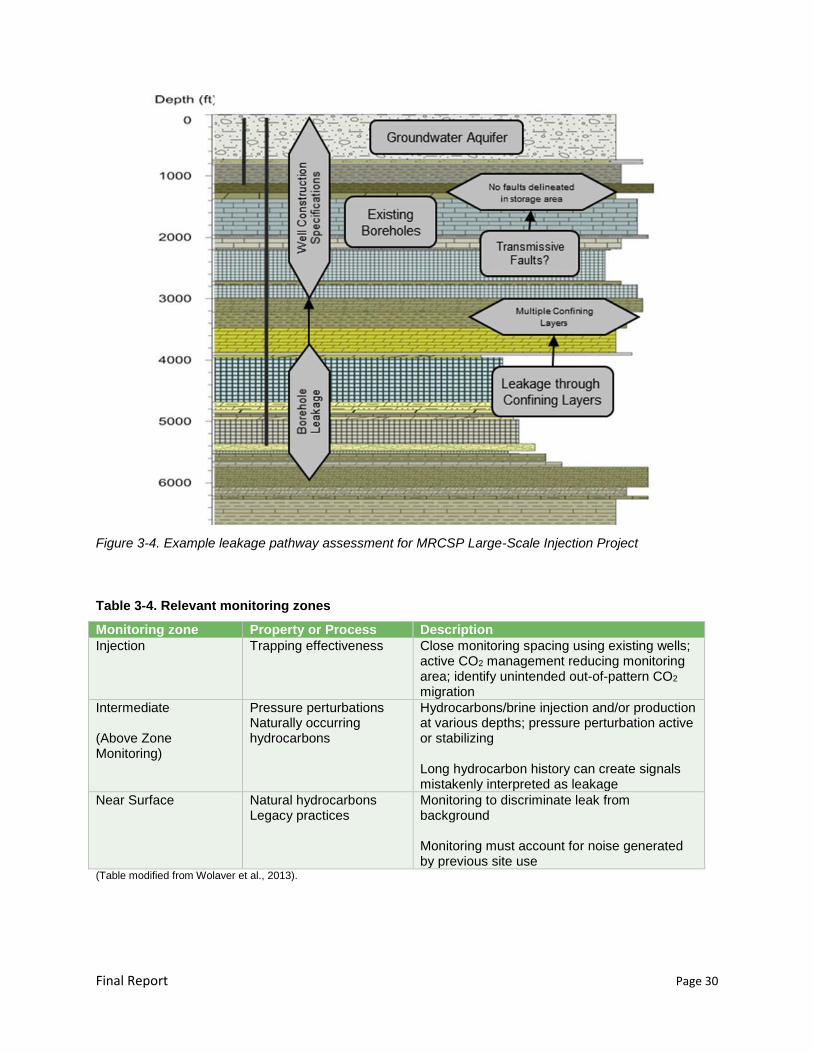
Final Report Page 30
Figure 3-4. Example leakage pathway assessment for MRCSP Large-Scale Injection Project
Table 3-4. Relevant monitoring zones
Monitoring zone Property or Process Description
Injection Trapping effectiveness Close monitoring spacing using existing wells; active CO2 management reducing monitoring area; identify unintended out-of-pattern CO2 migration
Intermediate (Above Zone Monitoring)
Pressure perturbations Naturally occurring hydrocarbons
Hydrocarbons/brine injection and/or production at various depths; pressure perturbation active or stabilizing Long hydrocarbon history can create signals mistakenly interpreted as leakage
Near Surface Natural hydrocarbons Legacy practices
Monitoring to discriminate leak from background Monitoring must account for noise generated by previous site use
(Table modified from Wolaver et al., 2013).
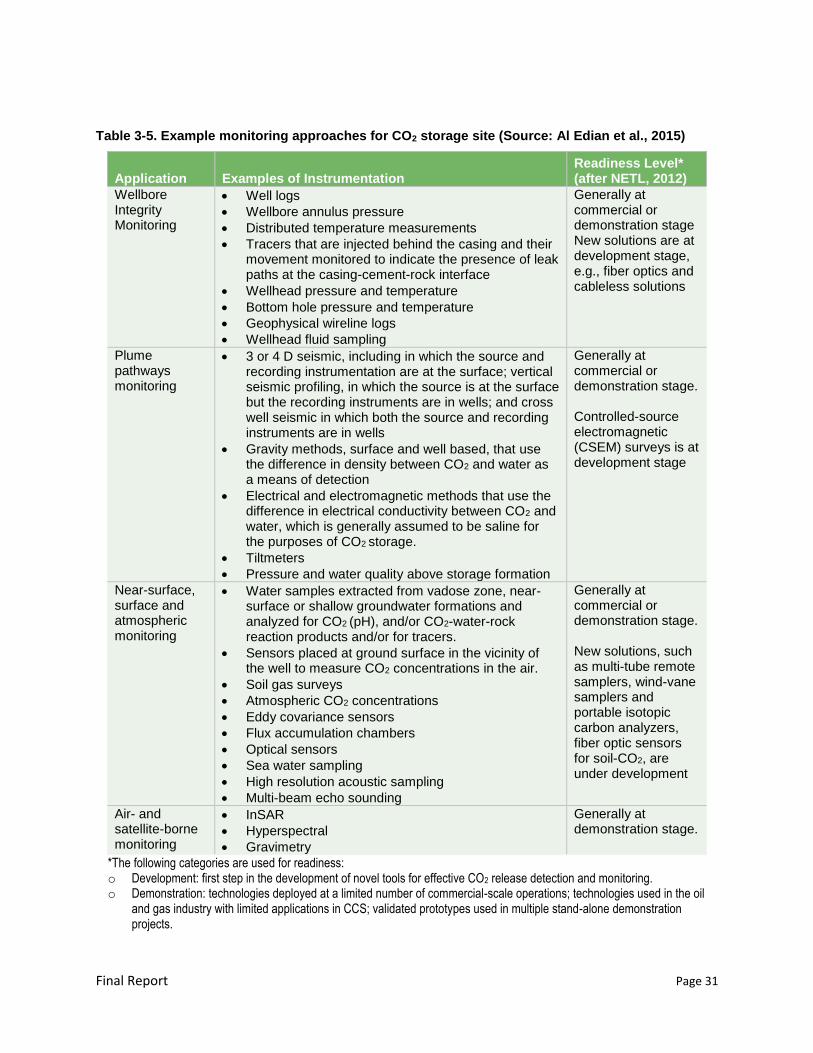
Final Report Page 31
Table 3-5. Example monitoring approaches for CO2 storage site (Source: Al Edian et al., 2015)
Application Examples of Instrumentation Readiness Level* (after NETL, 2012)
Wellbore Integrity Monitoring
Well logs
Wellbore annulus pressure
Distributed temperature measurements
Tracers that are injected behind the casing and their movement monitored to indicate the presence of leak paths at the casing-cement-rock interface
Wellhead pressure and temperature
Bottom hole pressure and temperature
Geophysical wireline logs
Wellhead fluid sampling
Generally at commercial or demonstration stage New solutions are at development stage, e.g., fiber optics and cableless solutions
Plume pathways monitoring
3 or 4 D seismic, including in which the source and recording instrumentation are at the surface; vertical seismic profiling, in which the source is at the surface but the recording instruments are in wells; and cross well seismic in which both the source and recording instruments are in wells
Gravity methods, surface and well based, that use the difference in density between CO2 and water as a means of detection
Electrical and electromagnetic methods that use the difference in electrical conductivity between CO2 and water, which is generally assumed to be saline for the purposes of CO2 storage.
Tiltmeters
Pressure and water quality above storage formation
Generally at commercial or demonstration stage. Controlled-source electromagnetic (CSEM) surveys is at development stage
Near-surface, surface and atmospheric monitoring
Water samples extracted from vadose zone, near-surface or shallow groundwater formations and analyzed for CO2 (pH), and/or CO2-water-rock reaction products and/or for tracers.
Sensors placed at ground surface in the vicinity of the well to measure CO2 concentrations in the air.
Soil gas surveys
Atmospheric CO2 concentrations
Eddy covariance sensors
Flux accumulation chambers
Optical sensors
Sea water sampling
High resolution acoustic sampling
Multi-beam echo sounding
Generally at commercial or demonstration stage. New solutions, such as multi-tube remote samplers, wind-vane samplers and portable isotopic carbon analyzers, fiber optic sensors for soil-CO2, are under development
Air- and satellite-borne monitoring
InSAR
Hyperspectral
Gravimetry
Generally at demonstration stage.
*The following categories are used for readiness: o Development: first step in the development of novel tools for effective CO2 release detection and monitoring. o Demonstration: technologies deployed at a limited number of commercial-scale operations; technologies used in the oil
and gas industry with limited applications in CCS; validated prototypes used in multiple stand-alone demonstration projects.
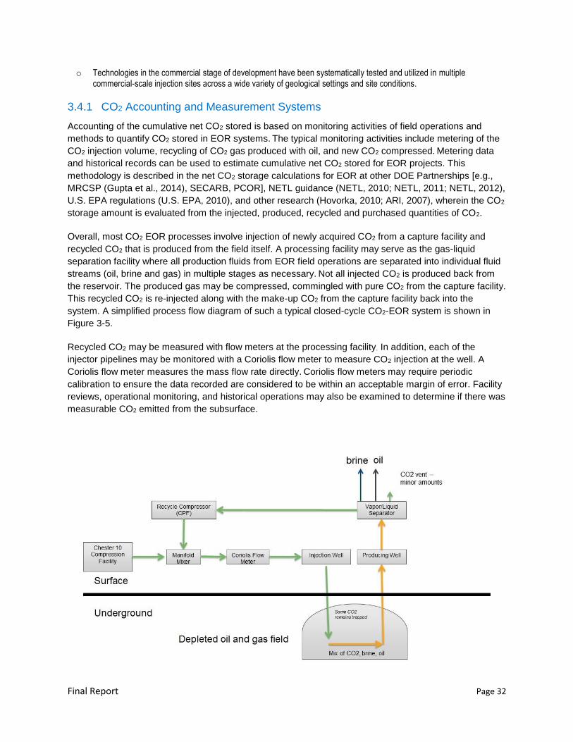
Final Report Page 32
o Technologies in the commercial stage of development have been systematically tested and utilized in multiple commercial-scale injection sites across a wide variety of geological settings and site conditions.
3.4.1 CO2 Accounting and Measurement Systems
Accounting of the cumulative net CO2 stored is based on monitoring activities of field operations and
methods to quantify CO2 stored in EOR systems. The typical monitoring activities include metering of the
CO2 injection volume, recycling of CO2 gas produced with oil, and new CO2 compressed. Metering data
and historical records can be used to estimate cumulative net CO2 stored for EOR projects. This
methodology is described in the net CO2 storage calculations for EOR at other DOE Partnerships [e.g.,
MRCSP (Gupta et al., 2014), SECARB, PCOR], NETL guidance (NETL, 2010; NETL, 2011; NETL, 2012),
U.S. EPA regulations (U.S. EPA, 2010), and other research (Hovorka, 2010; ARI, 2007), wherein the CO2
storage amount is evaluated from the injected, produced, recycled and purchased quantities of CO2.
Overall, most CO2 EOR processes involve injection of newly acquired CO2 from a capture facility and
recycled CO2 that is produced from the field itself. A processing facility may serve as the gas-liquid
separation facility where all production fluids from EOR field operations are separated into individual fluid
streams (oil, brine and gas) in multiple stages as necessary. Not all injected CO2 is produced back from
the reservoir. The produced gas may be compressed, commingled with pure CO2 from the capture facility.
This recycled CO2 is re-injected along with the make-up CO2 from the capture facility back into the
system. A simplified process flow diagram of such a typical closed-cycle CO2-EOR system is shown in
Figure 3-5.
Recycled CO2 may be measured with flow meters at the processing facility. In addition, each of the
injector pipelines may be monitored with a Coriolis flow meter to measure CO2 injection at the well. A
Coriolis flow meter measures the mass flow rate directly. Coriolis flow meters may require periodic
calibration to ensure the data recorded are considered to be within an acceptable margin of error. Facility
reviews, operational monitoring, and historical operations may also be examined to determine if there was
measurable CO2 emitted from the subsurface.
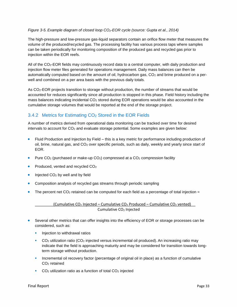
Final Report Page 33
Figure 3-5. Example diagram of closed loop CO2-EOR cycle (source: Gupta et al., 2014)
The high-pressure and low-pressure gas-liquid separators contain an orifice flow meter that measures the
volume of the produced/recycled gas. The processing facility has various process taps where samples
can be taken periodically for monitoring composition of the produced gas and recycled gas prior to
injection within the EOR reefs.
All of the CO2-EOR fields may continuously record data to a central computer, with daily production and
injection flow meter files generated for operations management. Daily mass balances can then be
automatically computed based on the amount of oil, hydrocarbon gas, CO2 and brine produced on a per-
well and combined on a per area basis with the previous daily totals.
As CO2-EOR projects transition to storage without production, the number of streams that would be
accounted for reduces significantly since all production is stopped in this phase. Field history including the
mass balances indicating incidental CO2 stored during EOR operations would be also accounted in the
cumulative storage volumes that would be reported at the end of the storage project.
3.4.2 Metrics for Estimating CO2 Stored in the EOR Fields
A number of metrics derived from operational data monitoring can be tracked over time for desired
intervals to account for CO2 and evaluate storage potential. Some examples are given below:
Fluid Production and Injection by Field – this is a key metric for performance including production of
oil, brine, natural gas, and CO2 over specific periods, such as daily, weekly and yearly since start of
EOR.
Pure CO2 (purchased or make-up CO2) compressed at a CO2 compression facility
Produced, vented and recycled CO2
Injected CO2 by well and by field
Composition analysis of recycled gas streams through periodic sampling
The percent net CO2 retained can be computed for each field as a percentage of total injection =
(Cumulative CO2 Injected – Cumulative CO2 Produced – Cumulative CO2 vented) Cumulative CO2 Injected
Several other metrics that can offer insights into the efficiency of EOR or storage processes can be
considered, such as:
Injection to withdrawal ratios
CO2 utilization ratio (CO2 injected versus incremental oil produced). An increasing ratio may
indicate that the field is approaching maturity and may be considered for transition towards long-
term storage without production.
Incremental oil recovery factor (percentage of original oil in place) as a function of cumulative
CO2 retained
CO2 utilization ratio as a function of total CO2 injected
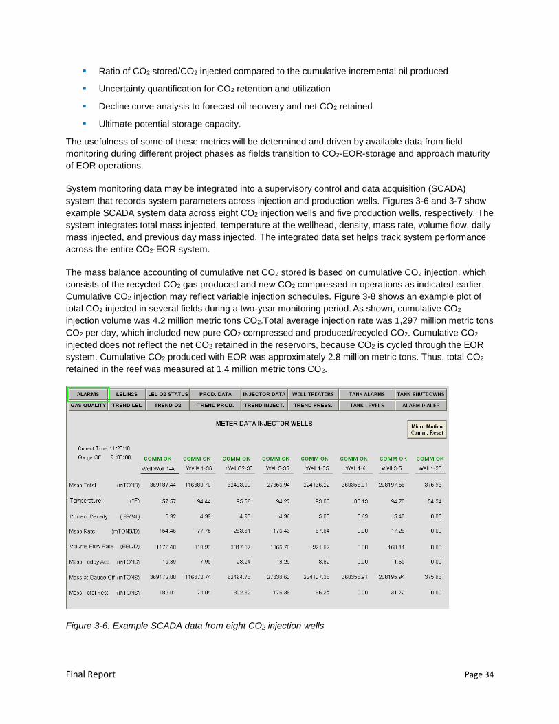
Final Report Page 34
Ratio of CO2 stored/CO2 injected compared to the cumulative incremental oil produced
Uncertainty quantification for CO2 retention and utilization
Decline curve analysis to forecast oil recovery and net CO2 retained
Ultimate potential storage capacity.
The usefulness of some of these metrics will be determined and driven by available data from field
monitoring during different project phases as fields transition to CO2-EOR-storage and approach maturity
of EOR operations.
System monitoring data may be integrated into a supervisory control and data acquisition (SCADA)
system that records system parameters across injection and production wells. Figures 3-6 and 3-7 show
example SCADA system data across eight CO2 injection wells and five production wells, respectively. The
system integrates total mass injected, temperature at the wellhead, density, mass rate, volume flow, daily
mass injected, and previous day mass injected. The integrated data set helps track system performance
across the entire CO2-EOR system.
The mass balance accounting of cumulative net CO2 stored is based on cumulative CO2 injection, which
consists of the recycled CO2 gas produced and new CO2 compressed in operations as indicated earlier.
Cumulative CO2 injection may reflect variable injection schedules. Figure 3-8 shows an example plot of
total CO2 injected in several fields during a two-year monitoring period. As shown, cumulative CO2
injection volume was 4.2 million metric tons CO2.Total average injection rate was 1,297 million metric tons
CO2 per day, which included new pure CO2 compressed and produced/recycled CO2. Cumulative CO2
injected does not reflect the net CO2 retained in the reservoirs, because CO2 is cycled through the EOR
system. Cumulative CO2 produced with EOR was approximately 2.8 million metric tons. Thus, total CO2
retained in the reef was measured at 1.4 million metric tons CO2.
Figure 3-6. Example SCADA data from eight CO2 injection wells
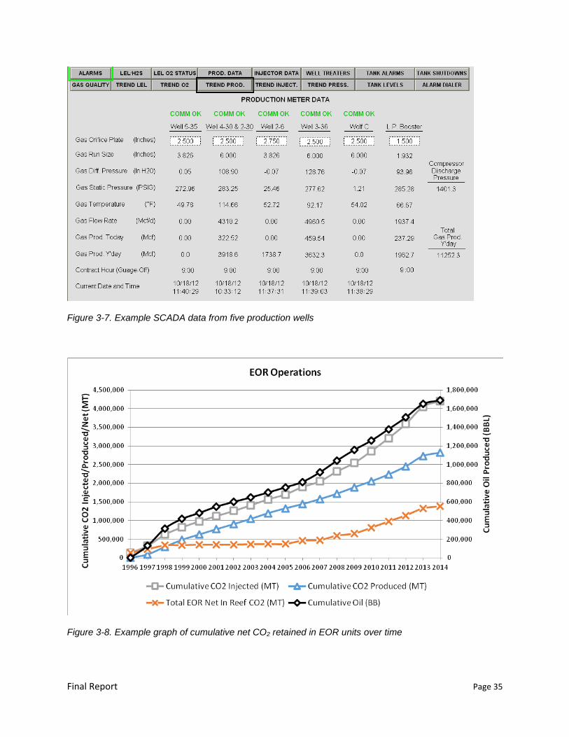
Final Report Page 35
Figure 3-7. Example SCADA data from five production wells
Figure 3-8. Example graph of cumulative net CO2 retained in EOR units over time
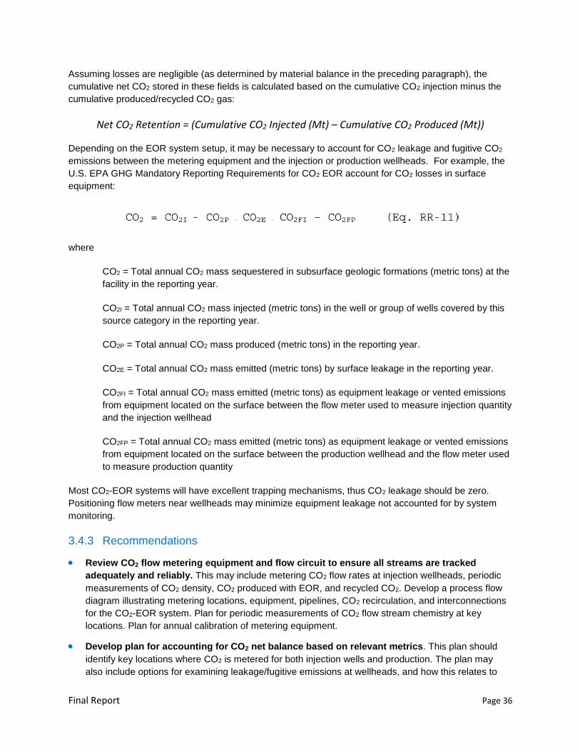
Final Report Page 36
Assuming losses are negligible (as determined by material balance in the preceding paragraph), the
cumulative net CO2 stored in these fields is calculated based on the cumulative CO2 injection minus the
cumulative produced/recycled CO2 gas:
Net CO2 Retention = (Cumulative CO2 Injected (Mt) – Cumulative CO2 Produced (Mt))
Depending on the EOR system setup, it may be necessary to account for CO2 leakage and fugitive CO2
emissions between the metering equipment and the injection or production wellheads. For example, the
U.S. EPA GHG Mandatory Reporting Requirements for CO2 EOR account for CO2 losses in surface
equipment:
where
CO2 = Total annual CO2 mass sequestered in subsurface geologic formations (metric tons) at the
facility in the reporting year.
CO2I = Total annual CO2 mass injected (metric tons) in the well or group of wells covered by this
source category in the reporting year.
CO2P = Total annual CO2 mass produced (metric tons) in the reporting year.
CO2E = Total annual CO2 mass emitted (metric tons) by surface leakage in the reporting year.
CO2FI = Total annual CO2 mass emitted (metric tons) as equipment leakage or vented emissions
from equipment located on the surface between the flow meter used to measure injection quantity
and the injection wellhead
CO2FP = Total annual CO2 mass emitted (metric tons) as equipment leakage or vented emissions
from equipment located on the surface between the production wellhead and the flow meter used
to measure production quantity
Most CO2-EOR systems will have excellent trapping mechanisms, thus CO2 leakage should be zero.
Positioning flow meters near wellheads may minimize equipment leakage not accounted for by system
monitoring.
3.4.3 Recommendations
Review CO2 flow metering equipment and flow circuit to ensure all streams are tracked
adequately and reliably. This may include metering CO2 flow rates at injection wellheads, periodic
measurements of CO2 density, CO2 produced with EOR, and recycled CO2. Develop a process flow
diagram illustrating metering locations, equipment, pipelines, CO2 recirculation, and interconnections
for the CO2-EOR system. Plan for periodic measurements of CO2 flow stream chemistry at key
locations. Plan for annual calibration of metering equipment.
Develop plan for accounting for CO2 net balance based on relevant metrics. This plan should
identify key locations where CO2 is metered for both injection wells and production. The plan may
also include options for examining leakage/fugitive emissions at wellheads, and how this relates to
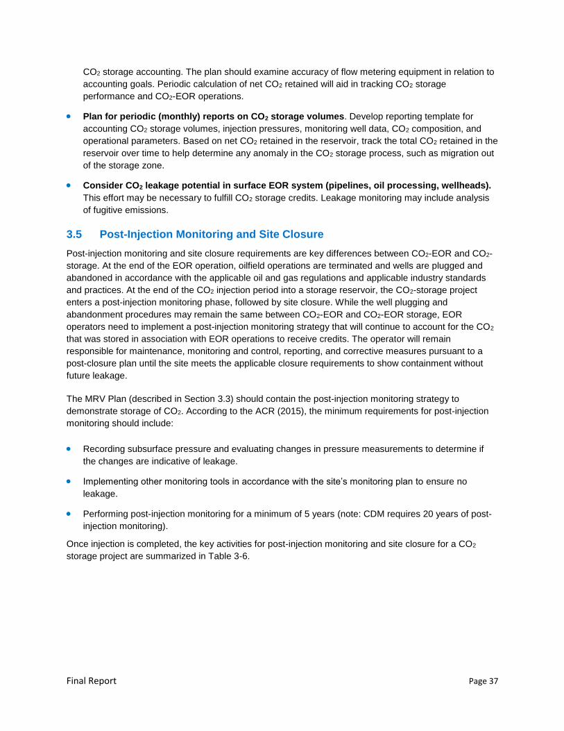
Final Report Page 37
CO2 storage accounting. The plan should examine accuracy of flow metering equipment in relation to
accounting goals. Periodic calculation of net CO2 retained will aid in tracking CO2 storage
performance and CO2-EOR operations.
Plan for periodic (monthly) reports on CO2 storage volumes. Develop reporting template for
accounting CO2 storage volumes, injection pressures, monitoring well data, CO2 composition, and
operational parameters. Based on net CO2 retained in the reservoir, track the total CO2 retained in the
reservoir over time to help determine any anomaly in the CO2 storage process, such as migration out
of the storage zone.
Consider CO2 leakage potential in surface EOR system (pipelines, oil processing, wellheads).
This effort may be necessary to fulfill CO2 storage credits. Leakage monitoring may include analysis
of fugitive emissions.
3.5 Post-Injection Monitoring and Site Closure
Post-injection monitoring and site closure requirements are key differences between CO2-EOR and CO2-
storage. At the end of the EOR operation, oilfield operations are terminated and wells are plugged and
abandoned in accordance with the applicable oil and gas regulations and applicable industry standards
and practices. At the end of the CO2 injection period into a storage reservoir, the CO2-storage project
enters a post-injection monitoring phase, followed by site closure. While the well plugging and
abandonment procedures may remain the same between CO2-EOR and CO2-EOR storage, EOR
operators need to implement a post-injection monitoring strategy that will continue to account for the CO2
that was stored in association with EOR operations to receive credits. The operator will remain
responsible for maintenance, monitoring and control, reporting, and corrective measures pursuant to a
post-closure plan until the site meets the applicable closure requirements to show containment without
future leakage.
The MRV Plan (described in Section 3.3) should contain the post-injection monitoring strategy to
demonstrate storage of CO2. According to the ACR (2015), the minimum requirements for post-injection
monitoring should include:
Recording subsurface pressure and evaluating changes in pressure measurements to determine if
the changes are indicative of leakage.
Implementing other monitoring tools in accordance with the site’s monitoring plan to ensure no
leakage.
Performing post-injection monitoring for a minimum of 5 years (note: CDM requires 20 years of post-
injection monitoring).
Once injection is completed, the key activities for post-injection monitoring and site closure for a CO2
storage project are summarized in Table 3-6.
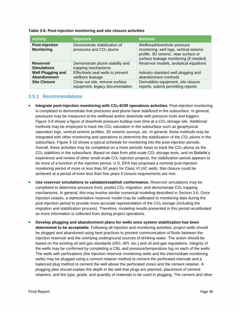
Final Report Page 38
Table 3-6. Post-injection monitoring and site closure activities
Activity Objective Methods
Post-injection Monitoring
Demonstrate stabilization of pressures and CO2 plume
Wellhead/downhole pressure monitoring, well logs, vertical seismic profile, 3D seismic, near surface or surface leakage monitoring (if needed)
Reservoir Simulations
Demonstrate plume stability and trapping mechanisms
Reservoir models, analytical equations
Well Plugging and Abandonment
Effectively seal wells to prevent wellbore leakage
Industry standard well plugging and abandonment methods
Site Closure Close out site, remove surface equipment, legacy documentation
Demobilize equipment, site closure reports, submit permitting reports
3.5.1 Recommendations
Integrate post-injection monitoring with CO2-EOR operations activities. Post-injection monitoring
is completed to demonstrate that pressures and plume have stabilized in the subsurface. In general,
pressures may be measured at the wellhead and/or downhole with pressure tools and loggers.
Figure 3-9 shows a figure of downhole pressure buildup over time at a CO2 storage site. Additional
methods may be employed to track the CO2 saturation in the subsurface such as geophysical
saturation logs, vertical seismic profiles, 3D seismic surveys, etc. In general, these methods may be
integrated with other monitoring and operations to determine the stabilization of the CO2 plume in the
subsurface. Figure 3-10 shows a typical schedule for monitoring into the post-injection periods.
Overall, these activities may be completed on a more periodic basis to track the CO2 plume as the
CO2 stabilizes in the subsurface. Based on data from pilot-scale CO2 storage tests, and on Battelle’s
experience and review of other small-scale CO2 injection projects, the stabilization period appears to
be more of a function of the injection period. U.S. EPA has proposed a nominal post-injection
monitoring period of more or less than 50 years for Class VI UIC wells. Site closure could be
achieved at a period of even less than five years if closure requirements are met.
Use reservoir simulations to validate/establish conformance. Reservoir simulations may be
completed to determine pressure front, predict CO2 migration, and demonstrate CO2 trapping
mechanisms. In general, this may involve similar numerical modeling described in Section 3.6. Once
injection ceases, a representative reservoir model may be calibrated to monitoring data during the
post-injection period to provide more accurate representation of the CO2 storage (including the
migration and stabilization process). Therefore, modeling results presented in this period recalibrated
as more information is collected from during project operations.
Develop plugging and abandonment plans for wells once system stabilization has been
determined to be acceptable. Following all injection and monitoring activities, project wells should
be plugged and abandoned using best practices to prevent communication of fluids between the
injection reservoir and the overlying underground sources of drinking water. The action should be
based on the existing oil and gas standards (ISO, API, etc.) and oil and gas regulations. Integrity of
the wells may be confirmed by completing a CBL and pressure/temperature log on each of the wells.
The wells with perforations (the injection reservoir monitoring wells and the intermediate monitoring
wells) may be plugged using a cement retainer method to cement the perforated intervals and a
balanced plug method to cement the well above the perforated zones and the cement retainer. A
plugging plan should explain the depth in the well that plugs are planned, placement of cement
retainers, and the type, grade, and quantity of materials to be used in plugging. The cement and other
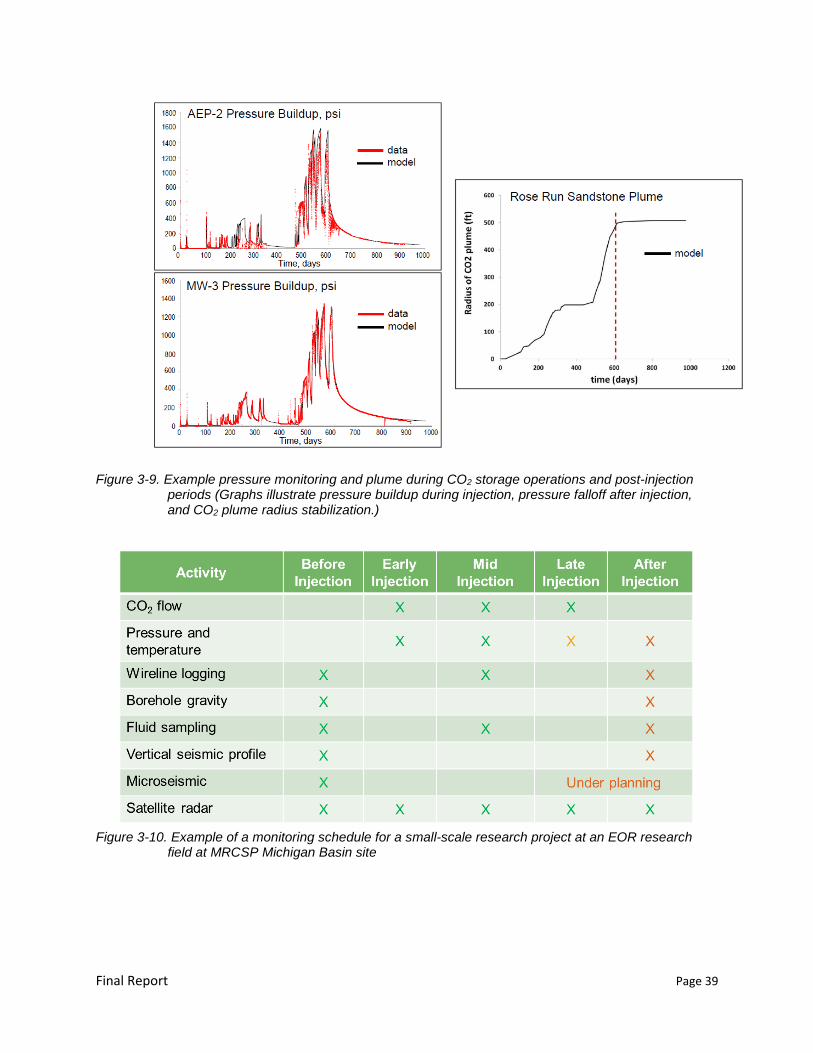
Final Report Page 39
Figure 3-9. Example pressure monitoring and plume during CO2 storage operations and post-injection periods (Graphs illustrate pressure buildup during injection, pressure falloff after injection, and CO2 plume radius stabilization.)
Figure 3-10. Example of a monitoring schedule for a small-scale research project at an EOR research
field at MRCSP Michigan Basin site
Final Report Page 40
materials in the storage zone must be compatible with the CO2 and water mixtures, so acid resistant
cement is recommended.
Close out the project once the conditions in the subsurface have stabilized and the wells have
been plugged. Relying on the information collected from the MRV Plan, the process of site closure
establishes that the injected CO2 is stored, there is a sufficient understanding of the characteristics of
the storage zone, and that the CO2 does not pose a leakage risk. This activity may include cessation
of injection and production operations, removal of surface equipment, site closeout reports, final
permitting, and documentation of the storage zone in oil and gas records.
Determine how to ensure permanent CO2 storage without limiting potential future oil
extraction. “Permanent” means either that GHG reductions are not reversible, or provide
mechanisms to replace any reversed GHG emission reductions to ensure that all credited reductions
endure for at least 100 years (for instance, if an EOR operator desires to use the CO2 in other
depleted oil and gas fields or if an unforeseen technology improvement allows for economical
extraction of stranded oil remaining in the reservoir). An approved accounting methodology may be
required to allow for CO2 to be utilized for future purposes.
Recognize post-closure site access and other liability concerns related to CO2 storage
integrity. EU directive requires financial instruments by the operator to ensure that closure and post-
closure obligations are met, as well as obligations to take corrective measures in case of leakages or
significant irregularities. See Section 4.2 for further discussion.
3.6 Economics
As discussed in Section 2, the barriers for pursuing co-optimized CO2 storage with EOR are primarily
economic. Developing a CO2-EOR storage project is a high capital-outlay venture. One reason is the
limited availability of a source of anthropogenic CO2 and the high cost of CO2 itself. The high cost of CO2
creates incentive for EOR operators to recycle CO2 rather than purchase new quantities. Another factor is
the cyclic nature of oil prices which makes capital intensive projects such as CO2-EOR less attractive as
operators seek to maximize profitability during high oil price periods by a combination of limiting the
number of EOR projects and recycling CO2.
Oil prices have the greatest impact on the economics of a project. The expenditures associated with CO2
are the largest project expense (amounting to nearly half the cost of revenue). The cost categories for
EOR include:
Well drilling and completion
Lease equipment for new producing wells and new injection wells
Converting existing production wells into injection wells
Reworking/transition costs from water flood to CO2-EOR
Operations and maintenance
CO2 recycle plant investment
Fluid transporting costs (including orifical list and re-injection)
CO2-hub distribution cost.
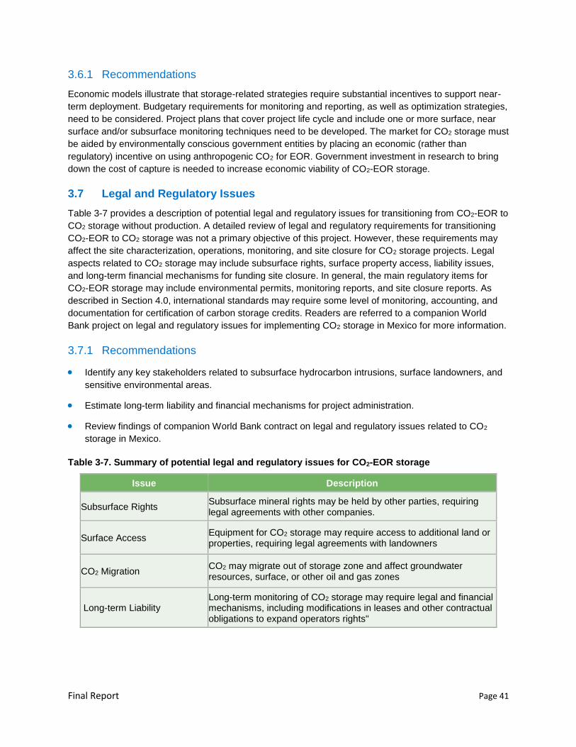
Final Report Page 41
3.6.1 Recommendations
Economic models illustrate that storage-related strategies require substantial incentives to support near-
term deployment. Budgetary requirements for monitoring and reporting, as well as optimization strategies,
need to be considered. Project plans that cover project life cycle and include one or more surface, near
surface and/or subsurface monitoring techniques need to be developed. The market for CO2 storage must
be aided by environmentally conscious government entities by placing an economic (rather than
regulatory) incentive on using anthropogenic CO2 for EOR. Government investment in research to bring
down the cost of capture is needed to increase economic viability of CO2-EOR storage.
3.7 Legal and Regulatory Issues
Table 3-7 provides a description of potential legal and regulatory issues for transitioning from CO2-EOR to
CO2 storage without production. A detailed review of legal and regulatory requirements for transitioning
CO2-EOR to CO2 storage was not a primary objective of this project. However, these requirements may
affect the site characterization, operations, monitoring, and site closure for CO2 storage projects. Legal
aspects related to CO2 storage may include subsurface rights, surface property access, liability issues,
and long-term financial mechanisms for funding site closure. In general, the main regulatory items for
CO2-EOR storage may include environmental permits, monitoring reports, and site closure reports. As
described in Section 4.0, international standards may require some level of monitoring, accounting, and
documentation for certification of carbon storage credits. Readers are referred to a companion World
Bank project on legal and regulatory issues for implementing CO2 storage in Mexico for more information.
3.7.1 Recommendations
Identify any key stakeholders related to subsurface hydrocarbon intrusions, surface landowners, and
sensitive environmental areas.
Estimate long-term liability and financial mechanisms for project administration.
Review findings of companion World Bank contract on legal and regulatory issues related to CO2
storage in Mexico.
Table 3-7. Summary of potential legal and regulatory issues for CO2-EOR storage
Issue Description
Subsurface Rights Subsurface mineral rights may be held by other parties, requiring legal agreements with other companies.
Surface Access Equipment for CO2 storage may require access to additional land or properties, requiring legal agreements with landowners
CO2 Migration CO2 may migrate out of storage zone and affect groundwater resources, surface, or other oil and gas zones
Long-term Liability Long-term monitoring of CO2 storage may require legal and financial mechanisms, including modifications in leases and other contractual obligations to expand operators rights"
Final Report Page 42
3.8 Recommended Next Steps
Despite the challenges imposed by the evolving regulatory and credit mechanisms, it is widely agreed
that the CO2-EOR projects provide a viable and economically attractive pathway for greenhouse gas
emission reduction and a potential bridge to storage in saline formations. However, there is a need to
build more project experience and test the various credit mechanisms under realistic conditions. For
Mexico, any planned EOR field tests, even if these are huff-n-puff or small-scale pilots offer an early
opportunity to build the practical knowledge and lay the foundation for successful credit accruals for future
full-scale projects. Therefore, it is recommended that the risk management, modeling, monitoring, and
accounting activities identified in this report be implemented and evaluated as a prototype in the
upcoming feasibility tests.
Figure 3-11 illustrates the layout of a hypothetical CO2-EOR storage project. The MRV plan should
include a delineation of the area that will be actively monitored as well as the broader maximum
monitoring area identified based on the extent of the injected CO2 over the long-term life of the project.
The areas are delineated such that the maximum monitoring area (inclusive of the active monitoring area)
features during the pre-injection characterization phase of the project. The MRV plan during the injection
through the closure phases of the CCUS project covers the active monitoring area. The maximum
monitoring area (inclusive of the active monitoring area) is once again examined during the post-closure
project phase as part of the MRV plan.
Figure 3-11. Hypothetical monitoring scheme

Final Report Page 43
The MRV Plan must be justified for the geologic and operational conditions at the site and is
complemented by integrated modeling and risk assessment activities that are continuously updated with
field data during the course of the project. The monitoring program should attempt to achieve reliable
accounting and leakage identification by efficiently tracking indicator parameters such as CO2 rates,
pressure, temperature and fluid phase compositions. These parameters are generally tracked in EOR
operations as part of the flood management exercise and are hence expected to be adequate for typical
reporting and accounting purposes. However, CCUS projects require that the MRV program demonstrate
and verify long-term geologic CO2 storage to obtain carbon credits. For this, additional monitoring-related
efforts would be based on the assessment and associated risk management of potential leakage
pathways over the lifetime of the CCUS project.
One recommendation is to approach the MRV using general ‘tiers’ of primary, secondary and tertiary
levels of monitoring implemented according to the results of the modeling and risk assessment activities.
As levels move from primary through to the tertiary, the intensity of effort involved, the number of
complementary technologies used and the frequency of monitoring could reduce. This enables the
monitoring system to focus on intensively targeting the most dynamic and probable ‘failure’ components
while ensuring additional levels of defenses to manage and restore system integrity in case of failure (i.e.,
leakage in this context). Project performance-based measures constituting primary requirements would
be standard field management tools to intensively and reliably track the bottomhole pressure, bottomhole
temperature, CO2 injection and production rates. These indicator parameters help evaluate formation and
well integrity as impacted by the most dynamic system component (i.e., injection zone). The injection
zone is dynamically subjected to varying pressures and contact with CO2 and is hence subjected to the
highest level of evaluation and operational control during the life of the project. The injection and
monitoring wells are highly instrumented components and are regulated to ensure least levels of
uncertainty with respect to geomechanical and geophysical system integrity. Pressures in a CO2-EOR
setting are regulated and vary within expected ranges depending on the pore volume replacement due to
injection and production operations. Any unexpected deviations in the pressure and temperature are an
expedient and reliable indicator of fluid migration into or out of that zone. In these cases, the secondary
levels of monitoring in the above-zone or overburden layers (intermediate zones) would be employed to
ensure leakage identification and quantification. Variations in the indicator parameters monitored in these
intermediate zones aid in tracking and mitigating any potential fluid migrating out of the injection zone.
The shallow zone and surface monitoring setup would be the tertiary level of defense that is judiciously
employed as an assurance of system integrity to maintain stakeholder confidence in the field operations.
Potential leakage pathways or ‘failure’ components need to be identified in the MRV Plan and their
evaluation, based on the risk assessment, is initially qualitative in nature. The potential system
components that could contribute to unwarranted migration of injected CO2 either as a free-phase or
dissolved-phase during CO2 EOR operations include wells (both existing operational as well as
abandoned), fractures and faults as well as structural features such as reservoir dip. Apart from a
thorough investigation of the well integrity, all operating wells and ‘high risk’ abandoned wells must be
instrumented to regularly track pressures with suggested built-in measurement redundancies. The
possibility of induced seismicity, both due to pre-existing faults and fluid injection activating transmissive
features as a result of increased pore pressures, needs to be assessed and managed if occurring.
Subsurface modeling complements a proactive monitoring strategy and provides supporting information
of each identified risk and associated uncertainties while considering the varying distribution of CO2 in
different fluid phases throughout the life of the project.
To judge if a particular measured parameter is a cause of concern, it is necessary to establish the
baseline conditions or the parameter range absent any leak. Pre-injection monitoring of different system

Final Report Page 44
components such as wells, injection zone, overburden and surface helps in understanding the acceptable
variability in key indicator parameters. Some surface monitoring may possibly be deployed in the primary
tier as part of the baseline monitoring and corrective action plan to address well integrity concerns.
Leakage verification and quantification may include more frequent monitoring of identified risk areas,
denser spatial coverage of the monitored region or the deployment of supplemental monitoring
technologies. Targeted leakage rates are to be measured and compared with detection capabilities of the
monitoring technologies used.
For CCUS projects quantifying storage credits, there is an additional post-injection monitoring period
where the operator has to demonstrate plume stabilization. The CO2 plume could be considered stable
depending on the rate of movement of the free-phase CO2 and/or the pressure changes over a certain
period of time. The operator could thus prove using both the trends of the post-injection monitoring results
and predictive reservoir modeling to show that the rate of the free-phase CO2 plume movement is lesser
than a certain threshold value in any direction and the pressure change on the reservoir is also lesser
than a certain threshold value.
Note that EOR operations contain monitoring that is only internally reported. In many cases, new and
different monitoring is not required for storage, but open reporting is required. The monitoring plan must
be known to get public support of credits. Common requirements for mechanisms offering credits for CO2-
EOR storage projects are discussed in the next section of this report.
Final Report Page 45
Chapter 4 International Framework for Receiving Credits
4.1 UNFCC Clean Development Mechanism (CDM)
The CDM provides an opportunity for nations not in Kyoto Protocol Annex I to contribute to GHG
reductions. CDM projects allow the creation of certified emission reductions (CERs) that can be used by
Annex I nations to help meet their GHG emission reduction requirements along with emission reduction
units. CDM projects are conducted in non-Annex I nations by public or private entities under
circumstances that satisfy all of the applicable requirements. Because Mexico is a non-Annex I nation,
there is the potential to conduct CDM projects in Mexico that would generate CERs that could be used by
Annex I nations to meet GHG emission reduction requirements. A project that achieves geologic storage
of CO2 in association with EOR has the potential to qualify as a CDM project.
The requirements for CO2 capture and storage in geological formations to be approved as CDM project
activities are governed by Decision 10/CMP.7 of the UNFCCC Conference of the Parties serving as the
meeting of the Parties to the Kyoto Protocol, including the detailed modalities and procedures set forth in
the Annex to that decision. These specific requirements supplement the general modalities and
procedures for a CDM as defined in Article 12 of the Kyoto Protocol established by Decision 3/CMP.1.
In addition to the normal eligibility requirements for CDM projects, a CCS project must meet more specific
requirements for:
a. Selection, characterization and development of geological storage sites
b. Risk and safety assessment
c. Environmental and socio-economic impact assessments to confirm the technical and environmental viability of the proposed CCS project activity
d. A project design document that addresses the specifics of operation and a monitoring plan
e. Documenting how project participants have secured the necessary rights to store CO2 in the targeted subsurface pore space
f. Protecting affected entities, individuals and communities against environmental damage, property damage or personal injury
g. Stopping, controlling or remediating any unintended seepage of CO2
h. Liability arrangements that meet the laws and regulations of the host Party as well as the UNFCCC requirements
i. Financial assurance provisions to cover at a minimum the costs of ongoing monitoring, any net reversal of storage, any required remedial measures, and verification and certification for at least 20 years after the project ends.
The boundary of a CCS project includes above-ground components, including the installation where the
CO2 is captured; any treatment facilities; transportation equipment, including pipelines and booster
stations along a pipeline, or offloading facilities in the case of transportation by ship, rail or road tanker;
any reception facilities or holding tanks at the injection site; the injection facility; and all subsurface
components, including the geological storage site and all potential sources of seepage, as determined

Final Report Page 46
during the characterization and selection of the geological storage site. The project boundary will also
encompass the vertical and lateral limits of the CO2 geological storage site that are expected to be
occupied by the CO2 plume as it stabilizes over the long term during the post-closure phases.
General baseline considerations are intended to “promote consistency, transparency and predictability”
and are designed to ensure that net reductions in anthropogenic emissions are real and measurable, and
provide an accurate reflection of what has occurred within the project boundary. They also address the
“additionality” requirement of Article 12, paragraph 5 (c) of the Kyoto Protocol, which specifies that
reductions in emissions must be “additional to any that would occur in the absence of the certified project
activity.” Finally, the determination of project boundaries should be made to include an accounting for all
GHG emissions as a part of the baseline assessment and monitoring.
CCS projects must be designed so that there are no significant risks of seepage, no significant
environmental or health risks, and provisions for compliance with all laws and regulations of the host
Party. The geological storage site must not be located in international waters. “All available evidence,
such as data, analysis and history matching, [must] indicate that the injected CO2 will be completely and
permanently stored such that, under the proposed or actual conditions of use, no significant risk of
seepage or risk to human health or the environment exists” (UNFCCC, 2012).
Characterization of the CCS project site calls for collection of sufficient data and information to
characterize the geological storage site and determine potential seepage pathways. To characterize the
geological storage site architecture and surrounding domains it is necessary to assess all known and
inferred structures within the injection and caprock formations to see if any would facilitate migration of
injected CO2. In particular, this involves 3D static earth modeling of the geological storage site. There will
also be an assessment of how the injected CO2 can be expected to behave within the geological storage
site architecture and surrounding domains, with a particular focus on the risk of seepage. Based on these
characterization steps, a site development and management plan is established to address the
preparation of the site, well construction, injection rates and maximum allowable pressure, operating and
maintenance protocols, as well as the timing and management of closure.
A comprehensive and thorough risk and safety assessment is required to assess the integrity of the
geological storage site and potential impacts on human health and ecosystems. The risk and safety
assessment must cover the full chain of the CCS project, provide assurance of safe containment of CO2,
yield operational data for the site development and management plan, take account of the effects of
potential induced seismicity or other geological impacts, and provide a basis for developing remedial
measures (including plans for responses to stop or control unintended CO2 emissions from surface CCS
installations or seepage). It should also include a communication plan.
Monitoring of CCS project activities is intended to provide assurance of the environmental integrity and
safety of the geological storage site, confirm that the injected CO2 is contained within the geological
storage site and within the project boundary, ensure that injected CO2 is behaving as predicted, ensure
that good site management is taking place, detect and estimate the flux rate and total mass of CO2 from
any seepage, determine whether timely and appropriate remedial measures have been carried out in the
event of seepage; and determine the reductions in anthropogenic emissions by sources of GHGs that
have occurred as a result of the registered CCS project activity.
Specifically, the monitoring plan should consider the range of technologies described in the 2006 IPCC
Guidelines for National Greenhouse Gas Inventories and other good practice guidance (IPCC, 2006). The
monitoring plan must specify which parameters and information will be monitored and collected, and the
Final Report Page 47
location and frequency of application of different monitoring techniques during the operational phase,
closure phase and post-closure phase of the CCS project. The plan will identify the techniques and
methods to detect and estimate the quantity of the CO2 stored in the geological storage site, detect
potential seepage via pathways in caprock formations, overburden and surrounding domains in the
geological storage site, and estimate the flux rate and total mass of any CO2 seepage. The plan will also
describe the process for history matching, using the monitoring results to calibrate and update the
numerical models used to characterize the geological storage site. To provide the necessary inputs, the
monitoring plan will also need to provide for:
measurement of the CO2 stream and composition
measurement of the temperature and pressure at the top and bottom of the injection well(s) and
observation well(s)
monitoring and measurement of various geological, geochemical and geomechanical parameters,
such as fluid pressures, displaced fluid characteristics, fluxes and microseismicity
monitoring and measurement of relevant parameters in the overburden and surrounding domains of
the geological storage site, such as the monitoring of groundwater properties, soil gas measurements
and measurements of the surface concentrations of CO2 in the air, which shall be calibrated to detect
signs of seepage, at an appropriate frequency
detection of corrosion or degradation of the transport and injection facilities.
Verification will be achieved by history matching and, where necessary, updating the numerical models
used to characterize the geological storage. The numerical models will be adjusted to address significant
deviations between observed and predicted behavior.
Monitoring of the geological storage site begins before injection activities to provide adequate collection of
baseline data. All monitoring should be conducted at appropriate frequencies and will not be terminated
earlier than 20 years after the end of the last crediting period of the CDM project, and then only if no
seepage has been observed at any time in the past 10 years and if all available evidence from
observations and modeling indicates that the stored CO2 will be completely isolated from the atmosphere
in the long term.
The CDM verification and certification process applies to all projects and for CCS projects focused on
determining whether the plans approved for the project are properly implemented, including the
monitoring plan, the site development and management plan, and any remedial measures and plans
described in the risk and safety assessment. Monitoring and operational data are to be analyzed and
compared with the initial modeling to determine whether significant deviations were observed during
history matching. If so, the process calls for a recharacterization of the geological storage site, an update
of the risk and safety assessment, an update of the environmental and socioeconomic impact
assessments, a revision to the project boundary, and a revision to the monitoring plan. In addition,
deviations from expected behavior require assessments to determine “whether seepage occurred from
the geological storage site of the CCS project activity during the verification period.” Where any seepage
has occurred, there must be an evaluation to whether a net reversal of storage has occurred and a
quantification of the amount of the net reversal for compensation purposes. At the end of the project, the
verification process must provide a determination that the geological storage site has been successfully
closed.
Final Report Page 48
4.2 European Union CCS Directive
In the European Union CCS is regulated under the EU CCS Directive on Geological Storage of CO2
(Directive 2009/31/EC), which became effective on June 25, 2009. As an enabling Directive, it does not
require CCS to be developed as a technology, but any CCS project must follow its provisions under
legislation enacted by the nation in which the project is located. The Directive primarily establishes the
legal framework for geological storage with little attention paid to capture or transport. It provides detailed
requirements that focus on selection of storage sites (Art. 4), exploration permits (Art. 5), storage permits
(Art. 6), operation, closure and post-closure obligations (Chapter 4) and provision for transfer of
responsibility (Art. 18).
Earlier, the European Union adopted its Emissions Trading Directive (Directive 2003/87/EC) (EU ETS),
which establishes a cap-and-trade program. CCS was not included in the original 2003 ETS Directive but
was added in 2009 (European Union Emissions Trading Directive Annex I [Directive 2009/29/EC]). CO2
that is captured, transported and stored according to the CCS Directive is considered as not emitted. Yet
the EU ETS does require that emission allowances must be purchased to compensate for any stored CO2
that escapes to the atmosphere. Currently, CO2 storage associated with EOR can qualify for full credit but
is subject to all of the requirements of the CCS Directive.
Under the EU ETS, companies receive or buy emission allowances which can be traded. Companies can
also buy limited amounts of international credits from emission-saving projects around the world to satisfy
their emission allowance requirements. The EU ETS chose to allow companies to buy international
credits to help incentivize investment in clean technologies and low-carbon solutions, particularly in
developing countries.
The European Union also seeks to encourage the establishment of cap-and-trade programs and other
new market mechanisms in developing countries by inviting them to connect with the EU ETS program to
create a system of globally linked economy-wide cap-and-trade systems. This goal has been given
additional momentum by the 2011 decision in Durban to set up a new market mechanism under the
UNFCCC. The European Union is also exploring the idea of setting up pilot programs in sectoral
crediting.
Under the new UNFCCC mechanism, verifiable and additional emission reductions achieved against
ambitious crediting thresholds would generate international credits. Sales of these credits could raise
revenues for the host countries while helping developed countries to meet their emission commitments
and EU ETS operators to comply with their obligations. Credits from this new market mechanism could be
used in addition to credits from the CDM or the Joint Implementation (JI) mechanism.
The EU ETS legislation allows participants to use most categories of CDM and JI project credits except
nuclear energy projects, afforestation or reforestation activities, and projects involving the destruction of
industrial gases. The European Union wants to see more use of standardized baselines and alternative
ways of assessing additionality. For advanced developing countries, the European Union seeks to have
CDM offsets replaced over time by the new market mechanism covering broad segments of the economy
and incentivizing net emission reductions. CDM would then be focused on least developed countries.
4.3 California Offset Credits
Assembly Bill 32 (AB 32), the California Global Warming Solutions Act of 2006 (AB 32, Statutes of 2006,
Chapter 488) charged the California Air Resources Board (ARB) with “monitoring and regulating sources
of emissions of greenhouse gases that cause global warming in order to reduce emissions of greenhouse

Final Report Page 49
gases” (Health and Safety Code section 38510). AB 32 required ARB to prepare a “scoping plan” for
achieving the maximum technologically feasible and cost-effective GHG emission reductions by 2020
(Health and Safety Code section 38561(a)). The AB 32 Scoping Plan identified a cap-and-trade program
as one of the strategies to reduce the GHG emissions. Under cap-and-trade, an overall limit on GHG
emissions from capped sectors is established by the cap-and-trade program and facilities subject to the
cap will be able to trade permits (allowances) to emit GHGs.
ARB approved the California Cap on Greenhouse Gas Emissions and Market-Based Compliance
Mechanisms Regulation (Cap-and-Trade Regulation) in October 2011. The regulation provides for the
establishment, administration, and enforcement of the California Greenhouse Gas Cap-and-Trade
Program by applying a statewide GHG emissions cap on covered entities and providing a mechanism for
trading instruments used to comply with the cap. The Cap-and-Trade Program provides flexibility about
how sources may comply with the overall cap. One alternative allows covered entities to use a limited
number of offset credits to satisfy a portion of their compliance obligation. An offset credit represents a
reduction or removal of GHGs by an activity that can be measured, quantified, and verified. Individual
offset projects can be implemented to generate offset credits, which can then be sold and used by a
covered entity as a compliance instrument in the Cap-and-Trade Regulation (ARB Cap-and-Trade
Regulation Instructional Guidance 6.2). The Cap-and-Trade Regulation allows offset projects to be
located in the United States, United States Territories, Canada, or Mexico. 17 California Code of
Regulations (CCR) §§95972(c) and 95973(a)(3). Although this criterion is established in the Regulation,
individual compliance offset protocols (COPs) may specify a more limited geographic area within that
range. For example, the protocol for Compliance Offset Protocol Livestock Projects, October 20, 2011, is
only applicable in the United States (ARB Cap-and-Trade Regulation Instructional Guidance 6.3).
An offset credit is equivalent to a GHG reduction or GHG removal enhancement of one metric ton of
CO2e (CO2 equivalent). The GHG reduction or GHG removal enhancement must be real, additional,
quantifiable, permanent, verifiable, and enforceable and may only be issued to offset projects using
approved COPs. At present there is no approved Compliance Offset Protocol for carbon capture and
geologic sequestration, but the regulation recognizes its potential use by defining the category of “CO2
Supplier” to be facilities that “capture a CO2 stream for purposes of supplying CO2 for commercial
applications or that capture the CO2 stream in order to utilize it for geologic sequestration where capture
refers to the initial separation and removal of CO2 from a manufacturing process or any other process.” 17
CCR §95802(a)(58). In establishing the compliance obligation for CO2 suppliers, the regulation provides
that the emissions exclude “CO2 verified to be geologically sequestered through use of a Board-approved
carbon capture and geologic sequestration quantification methodology that ensures that the emissions
reductions are real, permanent, quantifiable, verifiable, and enforceable” (17 CCR §95852(g)).
ARB has taken an initial step toward development of a quantification methodology for carbon capture and
geologic sequestration by contracting with Lawrence Berkeley National Laboratory to “conduct a scoping
study on existing carbon capture and storage quantification methodologies appropriate for California’s
specific geology and hydrology.” [CARB, Semi-Annual Report to the Joint Legislative Budget Committee
on Assembly Bill 32 (Chapter 488, Statutes of 2006), The California Global Warming Solutions Act of
2006 p. 14 (July 2014)]. This likely would lead to development of a monitoring, verification, and
accounting methodology that is appropriate for incorporation into the Cap-and-Trade Program.
There is a limited possibility for a project to qualify for offset credits under the early action provisions even
before ARB has approved a Compliance Offset Protocol. The early action provisions are designed to
recognize parties that made early reductions in GHGs. The Early Action Offset Program is limited in
scope and only allows GHG reductions or removal enhancements that occur within a specific time frame
Final Report Page 50
and achieve under approved quantification methodologies to qualify under the program. ARB may adopt
additional early action quantification methodologies; however, ARB will only adopt early action
quantification methodologies for project types for which it also adopts a Compliance Offset Protocol (ARB
Cap-and-Trade Regulation Instructional Guidance 6.14).
Early action emission offset credits (EAOCs) are issued by programs that must be approved by ARB,
referred to as Early Action Offset Programs. An Early Action Offset Program is a program that is approved
by ARB to issue early action offset credits. If the program is approved to be an Offset Project Registry
and has been issued an Executive Order, it qualifies as an Early Action Offset Program (ARB Cap-and-
Trade Regulation Instructional Guidance 6.14.2). All offset projects developed under an ARB Compliance
Offset Protocol must be listed with an ARB approved Offset Project Registry. Offset Project Registries will
help facilitate the listing, reporting, and verification of compliance offset projects, and issue registry offset
credits. ARB has approved three Offset Project Registries: ACR, Climate Action Reserve and Verified
Carbon Standard.
The ACR has an approved Methodology for Greenhouse Gas Emission Reductions from Carbon Capture
and Storage Projects (ACR, 2015), which is discussed in the following section in more detail. Eligible
projects under the methodology are those that “capture, transport and inject anthropogenic CO2 during
enhanced oil recovery (EOR) operations into an oil and gas reservoir located in the US or Canada where
it is sequestered.” (ACR, 2015, Page 1).
Early action offset credits must also meet the requirements for regulatory verification. If ARB determines
that an early action offset credit meets the requirements of the Regulation, the early action offset credit
must be retired or cancelled by the issuing Early Action Offset Program in its system before ARB will
issue an ARB offset credit that may be used for compliance purposes (ARB Cap-and-Trade Regulation
Instructional Guidance 6.14).
4.4 American Carbon Registry
In April 2015, the ACR approved a final methodology that outlines the requirements and process for CCS
Project Proponents that store CO2 in oil and gas reservoirs to qualify their projects for carbon credits
under the ACR program. The methodology is based on the accounting framework developed by the
Center for Climate and Energy Solutions (formerly the Pew Center on Global Climate Change) [A
Greenhouse Gas Accounting Framework for Carbon Capture and Storage Projects, Center for Climate
and Energy Solutions, February, 2012]. Projects are eligible that capture, transport and inject
anthropogenic CO2 during EOR operations into an oil and gas reservoir located in the U.S. or Canada.
Projects are required to have clear and uncontested ownership of the pore space and all necessary land
surface use rights to conduct post-injection monitoring activities and, if necessary, remediation.
Under the ACR program, project boundaries include a physical boundary, a temporal boundary, and a
GHG assessment boundary. The physical boundary encompasses all emission sources, and the
assessment boundary covers GHGs emissions from each source. The temporal boundary includes the
temporal parameters affecting project validity and the duration of required project activities, including all
monitoring.
The ACR CCS Methodology describes Baseline as a counterfactual scenario that forecasts the likely
stream of emissions or removals that would occur in the absence of the project, i.e., the "business as
usual" case. This serves as a reference case against which to compare GHG emissions associated with
the project and derive net emission reductions (ACR, 2015, page 9). The ACR CCS Methodology allows
the use of two different types of baselines “referred to as Projection-based and Standards-based.” ACR
Final Report Page 51
defines the Projection-based as “a baseline that would correspond with the project’s actual CO2 capture
site, absent the capture and compression system located at the CO2 source.” This calculation “uses data
collected in the project condition to represent the quantity of emissions prevented from entering the
atmosphere.” Alternatively, a “Standards-based baseline can be based on a technology or specified as an
intensity metric or performance standard (e.g., tonnes of CO2 equivalent [tCO2e] per unit of output).... A
Standards-based baseline is sector specific, at minimum, to ensure reasonable accuracy, and it could
have a different emissions profile than the technology used at the CO2 capture site.”
The ACR CCS Methodology provides a detailed set of quantification methodologies including a
“calculation procedure for the CO2 capture process [that] reflects the delineation of the boundary of the
capture site, which encompasses the source of CO2, as well as auxiliary equipment associated with the
CO2 capture and compression systems” (ACR, 2015, page 21). For transportation, the quantification
process “includes the full pipeline system from the CO2 delivery point at the capture site (downstream of
the compressor) to the CO2 delivery point at the storage site. The calculation methodology also applies to
CO2 transported in containers (e.g., by barge, rail or truck)” (ACR 2015, page 29).
“The emissions calculation procedures for CO2 storage cover direct CO2, CH4, and N2O emissions from
stationary combustion; CO2 and CH4 emissions from venting and fugitive releases to the atmosphere; and
indirect CO2e emissions from purchased electricity use. The procedures also account for any CO2 that is
produced with the hydrocarbons and transferred offsite (i.e., the CO2 is not re-injected into a reservoir that
is within the project boundary) and leakage of injected CO2 from the reservoir to the atmosphere. GHG
sources include CO2 receiving, injecting, recycling and re-injection equipment; CO2 injection and
production wells, hydrocarbon processing and storage facilities; and the CO2 storage reservoir” (ACR,
2015, page 35).
The ACR CCS Methodology recognizes that “any injected CO2 that is not produced with the oil remains
contained in the oil reservoir because of the confining layer above the oil reservoir that traps it in place.
This is the same confining layer that formed an effective seal and contained the oil and gas in the
reservoir for millions of years and now serves to trap the CO2. However, Project Proponents must quantify
atmospheric leakage of CO2 emissions from the storage volume, if they arise. Atmospheric leakage shall
be monitored during the entire Project Term, which includes the injection period and a time-period
following the end of injection as defined in Section 2.2. Methods to assure the long-term storage of CO2
beyond the Project Term will be required; these and associated reversal risk mitigation measures are
outlined in Section 5.4” (ACR, 2015, page 45).
The MRV Plan for CCS projects under the ACR CCS Methodology is required to include the following
components:
Determination of the storage volume that is expected to contain the injected CO2 during and after the
injection period, determined through modeling and flow simulations.
Identification of potential leakage pathways within this storage volume (usually well bores, faults, and
fractures). This information can also feed into the flow simulation model as a potential source of
uncertainty.
Remediation of potential leakage pathways, as needed. This can help reduce the probability of
leakage and reduce uncertainty in detecting atmospheric leakage.
Development of a monitoring strategy to demonstrate effective retention of anthropogenic CO2 during
injection and post-injection periods and for detection of the potential for atmospheric leakage.
Final Report Page 52
A strategy for quantifying any atmospheric leakage of CO2.
A plan for monitoring the following parameters:
Total volume of gas (containing CO2 and other compounds) produced from the primary process
Percentage of CO2 in the gas stream from the primary process
Units of output from the CO2 capture facility (e.g., MWh)
Non-captured CO2 emissions from the primary process
Stationary combustion emissions for CO2, CH4, and N2O
Indirect CO2 emissions from purchased and consumed electricity, steam, and heat
Vented and fugitive CO2 emissions from CO2 transport (mass balance)
Vented and fugitive CO2 emissions from CO2 storage
CO2 transferred offsite, and
Atmospheric leakage of CO2 from storage.
(ACR, 2015, page 55 and Table 5-3).
The monitoring strategy must be designed to demonstrate effective retention of the injected
anthropogenic CO2 within the production reservoir during and after injection. Based on site evaluation and
geological parameters, simulations of potential failure scenarios, and the sensitivities of individual
parameters to the outcomes of those simulations, the Project Proponent shall determine the specific
monitoring parameters to be monitored, the monitoring tools to be used, and the sampling frequency. A
fluid flow model is considered to be an essential component of the monitoring strategy. “Working with the
EOR operator, required data (existing and newly collected) shall be compiled to develop a fluid flow
model that is calibrated with production history and used to predict CO2 distribution during the injection
and post-injection phases of the EOR project” (ACR, 2015, page 57).
With respect to baseline monitoring, the ACR CCS Methodology states that, “depending on site-specific
conditions, the Project Proponent shall determine whether the monitoring approach would benefit from
establishing pre-injection levels.” If the decision is made to take these measurements, they should “be
done for a period of time that allows for the collection of data that are representative of site conditions
prior to the initiation of injection.”
Following completion of CO2 injection, it is still required that monitoring continue during the post-injection
phase until the end of the project to assure that no atmospheric leakage occurs, or if it does then to
quantify any leakage. The minimum post-injection monitoring period for CCS projects is five years (ACR,
2015, page 58). Project Proponents must demonstrate that the CO2 captured and stored is permanently
sequestered underground (ACR, 2015, page 76).
Since CCS projects involve capture, transport, and sequestration processes, which are often conducted
by different companies, the ownership to the title of CO2 credits associated with the project’s emission
reductions must be clearly defined. This can be done through contracts among the parties in which one of
the companies has clear ownership of the credits (ACR, 2015, page 76).
Final Report Page 53
4.5 Analogous Mechanism: Texas Railroad Commission
The Railroad Commission of Texas (RRC) adopted a rule in 2011 relating to Certification of Geologic
Storage of Anthropogenic CO2 Incidental to Enhanced Recovery of Oil, Gas, or Geothermal Resources.
16 TAC §§5.301 - 5.308, 36 Tex. Reg. 4397 (July 8, 2011). The RRC adopted the rule to implement
legislation that amended the Texas Water Code and the Texas Natural Resources Code to provide for the
implementation of projects involving the capture, injection, sequestration, or geologic storage of CO2. The
rule provides for certification of geologic storage of anthropogenic CO2 incidental to enhanced recovery
operations for which: (1) there is a reasonable expectation of more than insignificant future production
volumes or rates as a result of the injection of anthropogenic CO2; and (2) operating pressures are not
higher than reasonably necessary for enhanced recovery.
The rule requires the operator of the CO2 project to implement a monitoring, sampling, and testing (MST)
plan that starts with analysis of chemical and physical characteristics of the CO2 stream. It also requires
continuous monitoring of injection pressure, rate of injected CO2, and volume of injected CO2. The
operator must maintain the mechanical integrity of the injection wells and demonstrate external
mechanical integrity once every five years. Corrosion monitoring is required for well materials that will
come into contact with water for loss of mass, thickness, cracking, pitting, and other signs of corrosion. In
addition, the operator must “fill the annulus between the tubing and the long string casing with a corrosion
inhibiting fluid approved by the director.”
Annual monitoring of the injection zone pressure in the productive reservoir is required, supplemented by
a pressure falloff test at least once every five years. The rule also calls for monitoring wells “as needed for
continuous monitoring for pressure changes in an appropriately porous and permeable formation above
the confining zone” along with “periodic monitoring of the useable quality water strata overlying the
productive reservoir to monitor for changes in quality due to CO2 injection.” The plan also must use
“indirect, geophysical techniques to determine the position of the CO2 fluid front.”
To allow “an operator to make a determination by mass balancing or actual system modeling of the
quantities of anthropogenic CO2 permanently stored,” the plan must “ensure that the injected
anthropogenic CO2 is confined to the productive reservoir” and account for:
the volumes of anthropogenic CO2 injected into the productive reservoir
the anthropogenic CO2 separated from the enhanced recovery production
the anthropogenic CO2 entrained in the production
the volume of produced anthropogenic CO2 recycled for injection into the reservoir
any de minimis losses of anthropogenic CO2
the volume of make-up anthropogenic CO2 injected to the enhanced recovery project.
As an alternative to preparing a new MST plan for the enhanced recovery facility under the RRC rule, the
person registering the project and obtaining the storage certification may comply with the rule submitting
a copy of the information submitted to the U.S. EPA to comply with the Mandatory Reporting of
Greenhouse Gases: Injection and Geologic Sequestration of Carbon Dioxide.
In all cases, the operator “must use a master meter or a series of master meters to meter the total volume
of anthropogenic CO2 injected into the enhanced recovery facility.” In addition, the operator is required to
individual well meters to meter the volume of anthropogenic CO2 injected into each injection well. To
Final Report Page 54
address situations where anthropogenic CO2 is commingled outside the enhanced recovery facility with
other CO2, the operator is required to report “the total volume of anthropogenic CO2 in the mixed stream
and may account for the anthropogenic CO2 for the master meter and injected well volumes on an
allocated basis.” Essentially, the operator will be required to develop an accounting scheme and
demonstrate that it that will track the anthropogenic CO2 on a proportional basis that avoids overstating
the quantities of anthropogenic CO2 stored.
The rule adopted by the RRC is also noteworthy because a number of other states have begun to enact
legislation that would authorize their oil and gas regulators to certify the quantities of anthropogenic CO2
that incidentally stored in association with CO2 EOR operations. The RRC rule also served as a starting
point for the development of an ISO standard for the recognition and quantification of anthropogenic CO2
incidentally stored in association with CO2 EOR.
4.6 Conclusions
4.6.1 Consistent Requirements
The common thread that runs through all of the geologic storage methodologies for quantifying the
anthropogenic CO2 that is incidentally stored in association with EOR is the need to accurately determine
the actual GHG emission reductions achieved by the offset project. This starts with the establishment of a
project baseline that reflects a conservative estimate of business-as-usual performance. In most cases,
this includes consideration of GHG emissions associated with each step in the project chain from the
anthropogenic CO2 capture project, through processing and compression of the captured CO2,
transportation by pipeline or any other means, and into the EOR operation itself. Consideration includes
not only overt releases at every stage, such as through fugitive emissions or leakage, but also emissions
associated with power and energy usage at each stage. Although it typically will consider the CO2
entrained in the produced oil and gas sent to market, it does not typically include any consideration of
GHG emissions that might result from the eventual combustion of those fuels. Those emissions will be
considered in conjunction with the projects and operations in which that combustion occurs.
In some frameworks, such as California, there will be consideration not only of the “activity-shifting
leakage” described in the preceding paragraph, but also of “market-shifting leakage” that results from
relocation of activities. In those cases, the quantification process will require accounting for both the
activity-shifting leakage and the market-shifting leakage. “Activity-shifting leakage” means increased GHG
emissions or decreased GHG removals that result from the displacement of activities or resources from
inside the offset project’s boundary to locations outside the offset project’s boundary as a result of the
offset project activity. “Market-shifting leakage,” in the context of an offset project, means increased GHG
emissions or decreased GHG removals outside an offset project’s boundary due to the effects of an offset
project on an established market for goods or services.
All quantification frameworks will require some accounting for any uncertainty in the quantification of the
various factors included in the calculations. Where the equations for calculation are not dictated by the
quantification methodology, most regimes require detailed explanation of the process and equations that
have been used to calculate the storage quantities.
Most of these methodologies are also similar in requiring that the credited GHG emission reductions must
be real, additional, quantifiable, permanent, verifiable, and enforceable. Requiring that the emission
reductions (or emissions “removed” or “avoided”) be “additional” (sometimes called an “additionality”
requirement) means that the GHG emission reductions must exceed any reductions or removals
Final Report Page 55
otherwise required and must also exceed any that would otherwise occur in a conservative business-as-
usual scenario. Requiring that the reductions be “enforceable” means there must be authority to hold a
particular party liable for taking the steps necessary to result in the reductions and to take appropriate
enforcement action for any violations. The requirement that reductions be “permanent” means either that
GHG reductions are not reversible, or that the credit management regime provides mechanisms to
replace any reversed GHG emission reductions to ensure that all credited reductions endure for at least
100 years. Requiring that the reductions be “quantifiable” means there must be an ability to accurately
measure and calculate the GHG reductions or removals relative to a project baseline in a reliable and
replicable manner, while accounting for the uncertainty, for activity-shifting leakage and for market-shifting
leakage if that is also required. Requiring that reductions be “verifiable” means that an offset assertion is
well documented and transparent, such that it lends itself to an objective review by an accredited
verification body.
A requirement that the GHG reductions be “real” amounts to a reiteration of all of these characteristics
and means that any credited GHG reductions or GHG enhancements must result from a demonstrable
action or set of actions, and that they are quantified using appropriate, accurate, and conservative
methodologies that “account for all GHG emissions sources, GHG sinks, and GHG reservoirs within the
offset project boundary.”
4.6.2 Legal and Regulatory Issues for Qualifying for Credits
Under the European Union Emission Trading System Directive, an offset project involving the incidental
storage of anthropogenic CO2 in association with an EOR project in Mexico could be creditworthy if it
meets the requirements of the CDM CCS methodology. Because no such projects have been considered
and credited to date, however, uncertainty surrounds the qualification process. Practical implementation
will be indispensable to qualification without imposing untenable economic costs. Moreover, recent policy
expressions within the European Union suggest movement toward replacing CDM offsets by a new
market mechanism covering broad segments of the economy and incentivizing net emission reductions.
Under such a new regime, the qualification of offsets would be focused on projects in least developed
countries.
For the California Cap-and-Trade Program, although an offset project in Mexico has the potential to
qualify for credit, significant steps must be accomplished before the availability of credit could be a reality.
Most importantly, the California ARB needs to approve a Compliance Offset Protocol for CO2 geologic
sequestration associated with EOR. In addition, that approved protocol must include Mexico within
approved project area. Before that process is completed, it would also be useful to have California ARB
approval of an early action quantification methodology for geologic sequestration associated with CO2
EOR. This approval could be based on ACR protocol, but that protocol would need to be expanded to
include Mexico in addition to the U.S. and Canada.
4.6.3 Summary and Concerns
GHG mitigation frameworks and protocols support carbon storage associated with CO2-EOR as a
reduction technology that can be credited when used in an offset project. These include UNFCCC Clean
Development Mechanism, European Union Directives, California offsets, ACR and others. More
importantly, CO2-EOR projects demonstrating carbon storage in Mexico may be eligible for credits. The
protocols typically outline requirements as performance measures without prescribing technologies to
meet these requirements. Accordingly, there is significant flexibility for the project proponent to fashion
the project details and submit for approval plans that describe how requirements will be met.
Nevertheless, as described herein, there are significant non-technical hurdles that may constrain or

Final Report Page 56
prevent CO2-EOR projects from meeting the requirements include the lack of an approved California
Compliance Offset Protocol for carbon capture and geologic sequestration and the fact that the existing
ACR protocol that could play a role in the California offsets program currently excludes projects in Mexico.
The lack of experience with applying CDM and European Union protocols to CCS projects in general and
to EOR projects in particular could prove a hindrance, as could the absence of any provisions in these
protocols that are specifically tailored to oil field operations. Although the ongoing process for developing
ISO standards for CO2 capture, transportation and storage, specifically including the incidental storage of
anthropogenic CO2 in association with EOR promises to provide a better pathway to credits, final
standards are still several years away. Other potential hindrances could come in the form burdensome
quantification and reporting requirements and in the form of long-lived and cumbersome post-closure
operator and host nation obligations.
Final Report Page 57
Chapter 5 References
Advanced Resources International. 2007. CO2-EOR: An Enabling Bridge for the Oil Transition. American Energy Security Summit, April 2007
Advanced Resources International Inc. (ARI) and Melzer (Melzer Consulting), 2010. Optimization of CO2
Storage in CO2 Enhanced Oil Recovery Projects. Department of Energy & Climate Change (DECC), Office of Carbon Capture & Storage, November 30.
Al Eidan, A.A., Bachu, S., Melzer, L.S. 2015. Technical Challenges in the Conversion of CO2-EOR
Projects to CO2 Storage Projects.SPE Paper 174575-MS. Azzolina, N.A., D.V. Nakles, C.D. Gorecki, W.D. Peck, S.C. Ayash, S. Melzer, S. Chatterjee. 2015. CO2
Storage Associated with CO2 Enhanced Oil Recovery. International Journal of Greenhouse Gas Control, Vol. 37, p. 384-397.
American Carbon Registry (ACR). 2015. Methodology for Greenhouse Gas Emission Reduction from
Carbon Capture and Storage Projects. Bandza, A.J. and Vajjhala, S.P. 2014. Modeling the Transition from Enhanced Oil Recovery to Geologic
Carbon Sequestration. Managerial Decision Economics, Vol. 35(1), p. 20-35. Celia, Michael A., Stefan Bachu, Jan Martin Nordbotten, Sarah E. Gasda, and Helge K. Dahle. 2004.
Quantitative Estimation of Co2 Leakage from Geological Storage: Analytical Models, Numerical Models, and Data Needs. GHGT 7, Vancouver, Canada.
CSLF (Carbon Sequestration Leadership Forum). 2013. Final Report by the CSLF Task Force on
Technical Challenges in the Conversion of CO2-EOR Projects to CO2 Storage Projects. Computer Modeling Group Ltd. (CMG). 2010. GEM- Advanced Compositional and GHG Reservoir
Simulator, User’s Guide. Computer Modeling Group Ltd., Calgary, Alberta. Dai, Z., H. Viswanathan, J. Fessenden-Rahn, R. Middleton, F. Pan, W. Jia, S-Y. Lee, B. McPherson, W.
Ampomah, R. Grigg. 2014. Uncertainty Quantification of CO2 Sequestration and Enhanced Oil Recovery, Energy Procedia, Vol. 63, p. 7685-7693.
Dávila, M., O. Jiménez, et al. 2010. "A preliminary selection of regions in Mexico with potential for
geological carbon storage." International Journal of Physical Sciences 5(5): 408-414. Ettehadtavakkol, A., L.W. Lake, S.L. Bryant. 2014. CO2-EOR and Storage Design Optimization.
International Journal of Greenhouse Gas Control, Vol. 25, p. 79-92. Gasda S, Bachu S, Celia M. The potential for CO2 leakage from storage sites in geological media:
Analysis of well distribution in mature sedimentary basins. Environ Geol 2000; 46 (6-7):707-20. Godec, M.L. 2011. "Global technology roadmap for CCS in industry sectoral assessment CO2 enhanced
oil recovery." Prepared by Advanced Resources International, Inc. for United Nations Industrial Development Organization, Arlington, VA, USA.
Gupta, N., Paul, D., Cumming, L., Place, M., Mannes, R., 2014. Testing for Large-scale CO2-enhanced
Oil Recovery and Geologic Storage in the Midwestern USA, Energy Procedia, Volume 63, 2014, Pages 6393-6403, ISSN 1876-6102, http://dx.doi.org/10.1016/j.egypro.2014.11.674.
Final Report Page 58
Hadlow, R.E.1992. Update of Industry Experience with CO2 Injection. Paper SPE 24928 presented at the 67th Annual Technical Conference and Exhibition of the Society of Petroleum Engineers,Washington, D.C., 4–7 October.
Hill, B., S. Hovorka, S. Melzer. 2013 Geologic Carbon Storage through Enhanced Oil Recovery. Energy
Procedia, Vol. 37, p. 6808-6830. Hovorka, S.D. 2010. EOR as Sequestration—Geoscience Perspective. White Paper for Symposium on
Role of EOR in Accelerating Deployment of CCS. 26 p. Huerta, N.J., Checkai, D.A. and Bryant, S.L. 2009. Utilizing Sustained Casing Pressure Analog to Provide
Parameters to Study CO2 Leakage Rates Along a Wellbore. Paper SPE 126700 presented at the SPE International Conference on CO2 Capture, Storage and Utilization, San Diego, California, 2-4 November 2009.
Intergovernmental Panel on Climate Change (IPCC). 2005. Carbon Capture and Storage. Metz, B.,
Davidson, O., de Coninck, H., Loos, M., and Meyer, L. editors. Prepared by Working Group III of the IPCC. Cambridge University Press.
IPCC. 2006. 2006 IPCC Guidelines for National Greenhouse Gas Inventories, Prepared by the National Greenhouse Gas Inventories Programme, Eggleston H.S., Buendia L., Miwa K., Ngara T. and Tanabe K.
(eds). published: IGES, Japan. Jafari, A. and J. Faltinson. 2013. Transitioning of Existing CO2-EOR Projects to Pure CO2 Storage
Projects. SPE 167180. SPE Unconventional Resources Conference Canada, Society of Petroleum Engineers.
Jessen, K., A.R. Kovscek, F.M. Orr, Jr. 2005. Increasing CO2 Storage in Oil Recovery. Energy
Conservation and Management. Vol. 46, p. 293-311. Kelley, M., S. Mishra, S. Mawalkar, M. Place, N. Gupta, M. Abbaszadeh, R. Pardini. 2014. Reservoir
characterization from pressure monitoring during CO2 injection into a depleted pinnacle reef – MRCSP commercial-scale CCS demonstration project. Energy Procedia, Vol. 63, p. 4937-4964.
Kuuskraa, V. and M. Wallace. 2014. CO2-EOR Set for Growth as New CO2 Supplies Emerge. Oil Gas J.
May, 2014, pp. 92–105. Lacy, R., C. Serralde, et al. (2013). "Initial assessment of the potential for future CCUS with EOR projects
in Mexico using CO2 captured from fossil fuel industrial plants." International Journal of Greenhouse Gas Control 19: 212-219.
Law, D., Huang, S., Freitag, N., Perkins, E., Wassmuth, F., Dunbar, B., and Asghari, K. (2004): Theme 3:
CO2 storage capacity and distribution predictions and the application of economic limits; in Wilson, M. and Monea, M. (eds.), IEA GHG Weyburn CO2 Monitoring and Storage Project Summary Report 2000-2004, Petroleum Technology Research Center, Regina, Saskatchewan, Canada, 2004.
Popoola, L.K. , Grema, A.S., Latinwo, G.K., Gutti, B., and Balogun, A.S. 2013. Corrosion problems during
oil and gas production and its mitigation. International Journal of Industrial Chemistry, 4:35, 15 p.Manrique, E.J., V.E. Muci, M.E. Gurfinkel. 2007. EOR Field Experiences in Carbonate Reservoirs in the United States. SPE Reservoir Evaluation & Engineering, December.
Melzer, S. 2012. CO2 EOR: Factors involved in Adding Carbon Capture, Utilization and Storage (CCUS)
to Enhanced Oil Recovery. Center for Climate and Energy Solutions.
Final Report Page 59
Merchant, D.H. 2010. Life Beyond 80: a Look at Conventional WAG Recovery Beyond 80% HCPV Injection in CO2 Tertiary Floods. SPE 139516 presented at SPE International Conference on CO2 Capture, Storage, and Utilization, New Orleans, Louisiana, 10–12 November 2010.
National Energy Technology Laboratory. 2010. Carbon Dioxide Enhanced Oil Recovery, Untapped
Domestic Energy Supply and Long Term Carbon Storage Solution. US DOE, Report, March 2010. 32 p.
National Energy Technology Laboratory. 2011. Improving Domestic Energy Security and Lowering CO2 Emissions with “Next Generation” CO2-EOR, US DOE, Report No. DOE/NETL-2011/1504, June 20, 2011.
National Energy Technology Laboratory. 2012. Best Practices for Monitoring, verification, and accounting
of CO2 stored in deep geologic formations: DOE/NETL-2012/1568. 127 p. National Energy Technology Laboratory. 2013. Risk Analysis and Simulation for Geologic Storage of CO2:
DOE/NETL-2013/1603. 67 p Nordbotten, J.M., M.A. Celia, S. Bachu. 2004. Analytical Solutions for Leakage Rates through Abandoned
Wells. Water Resources Research, Vol. 40, DOI: 10.1029/2003WR002997. Oldenburg, C.M., Bryant, S.L, and Nicot, J.-P. 2009. Certification Framework Based on Effective Trapping
for Geologic Carbon Sequestration. Int. J. of Greenhouse Gas Control, 3 (2009), pp. 444–457. Pawar, Rajesh, Bromhal, Grant, et. al. 2014. Quantification of Key Long-term Risks at CO2 Sequestration
Sites: Latest Results from US DOE's National Risk Assessment Partnership (NRAP) Project. Energy Procedia, Vol. 63, p. 4816-4823.
Peterson, J.A. 1983. Petroleum geology and resources of southeastern Mexico, northern Guatemala, and
Belize, US Department of the Interior. Ramirez Salizar, J.E. 2009. Coupled CO2 Sequestration and Enhanced Oil Recovery Optimization using
Experimental Design and Response Surface Methodology. MS Thesis, Department of Petroleum Geosciences Engineering, the University of Texas at Austin.
Ravi Ganesh, P., Mishra, S., Mawalkar, S., Gupta, N. and Pardini, R. 2014. Assessment of CO2 injectivity
and storage capacity in a depleted pinnacle reef oil field in northern Michigan. Energy Procedia, Vol. 63, p. 2969-2976.
Robles-Nolasco, J., E. Pliego-Vidal, et al. 2004. Offshore Neogene plays, Salina del Istmo Basin,
southeast of Mexico: Tulsa, Oklahoma, EUA. American Association of Petroleum Geologists, International Conference, October.
Savage, D., Maul, P.R., Benbow, S., and Walke, R.C., 2004. A Generic FEP Database for the
Assessment of Long-Term Performance and Safety of the Geological Storage of CO2, Version 1.0. Quintessa Document # QRS-1060A-1.
Soto-Cuervo, A., V. Ortega-Gonzalez, et al. 2009. "Present and future of the Salina del Istmo basin and
its offshore extension into the Gulf of Mexico Schlumberger. 2012. Eclipse Reference Manual. Stauffer, P.H., Viswanathan, H.S., Pawar, R.J., and Guthrie, G.D. 2009. A System Model for Geologic
Sequestration of Carbon Dioxide. Environ. Sci. Technol., 43(3), 565-570. UNFCC. 2012. UNFCC Conference of the Parties held in Durban from 28 November to 11 December
2011, Addendum, Part Two: Action taken by the Conference of the Parties serving as the meeting of the Parties to the Kyoto Protocol at its seventh session (15 March 2012).
Final Report Page 60
U.S. EPA. 2010. General Technical Support Document for Injection and Geologic Sequestration Of Carbon Dioxide: Subparts RR and UU Greenhouse Gas Reporting Program. Office of Air and Radiation.
U.S. EPA. 2013. Draft Underground Injection Control (UIC) Program Guidance on Transitioning Class II
Wells to Class VI Wells (December 2013).
U.S. EPA. 2015. Memorandum "Key Principles in EPA's Underground Injection Program Class VI Rule
Related to Transition of Class II Enhanced Oil or Gas Recovery Wells to Class VI." April 23. Wolaver, B.D., S.D. Hovorka, et al. 2013. "Greensites and brownsites: Implications for CO 2
sequestration characterization, risk assessment, and monitoring." International Journal of Greenhouse Gas Control 19: 49-62.
World Resources Institute (WRI). 2008. CCS Guidelines: Guidelines for Carbon Dioxide Capture,
Transport, and Storage. Washington, DC. Zhou, W., M.J. Stenhouse, R. Arthur, S. Whittaker, S. Law, R. Chalaturnyk, W. Jazrawi. 2004. The IEA
Weyburn CO2 Monitoring and Storage Project—Modeling of the Long-Term Migration of CO2 from Weyburn, In Proceedings of the 7th International Conference on Greenhouse Gas Control Technologies, p. 721-730.

Appendix A: Literature Review Summaries
A-1
1. OVERVIEW
Battelle conducted a literature review to assess current expert views on issues concerning geological
storage, either by transition of carbon dioxide (CO2)-enhanced oil recovery (EOR) to storage, or by
combining CO2-EOR with storage; identify key issues that need to be addressed in the Mexican context;
and provide recommendations to PEMEX on how to implement the required measures that will enable
CO2-EOR projects to qualify for geological storage. The survey included primarily literature identified by
the client and additional literature. Sources of information published between 2008 and 2015 are
reviewed in detail below, including journal papers, independent consulting reports, research papers, and
guidance documents. Collectively, the literature explored technical and economic issues, risk
assessment, monitoring, reporting, verification, and accounting requirements, and other topical matters.
2. Literature Review: Discussion and Key Points
2.1 Final Report by the CSLF Task Force on Technical Challenges in the Conversion of CO2-EOR Projects to CO2 Storage Projects (CSLF, 2013)
This 2011 report conducted for the Carbon Sequestration Leadership Forum (CSLF) served primarily as a
comprehensive summary on various issues surrounding the use of CO2 for EOR and/or CO2
sequestration operations. The report acknowledges economic and policy-related barriers but steers clear
of any detailed discussion on that subject, considering it to be beyond the study’s scope. Instead, the
study focuses mainly on technical decisions associated with each end of the spectrum – CO2 EOR and
CO2 storage – as well the intermediate zones of dual CO2-EOR/carbon capture and storage (CCS) and
the projects transitioning from CO2-EOR to CO2 storage. Particularly relevant for our purposes are the
discussions surrounding regulatory requirements, monitoring and surveillance (M&S), and site selection
criteria for each type of project in this spectrum. Overall, the fundamental challenges for all such CO2
projects, transitory or otherwise, are not technical in nature.
The CSLF report’s most salient findings are as follows:
1. For projects in the middle of the spectrum, the absence of baseline data for monitoring and the lack of
a well-established regulatory and legal framework present a unique challenge.
2. CO2 injection wells in EOR projects must meet well-established Class II regulations that place strict
controls on the construction and operation of these wells. The construction regulations specify
standards for cementing, casing, and testing the well for integrity via logging and other means, while
the operations regulations stipulate that the operator must monitor the nature of injected fluid, the
injection pressure (so as not to create new fractures), flow rates, and cumulative volumes.
3. The regulatory requirements for CO2 storage are typically similar to those of CO2-EOR, with additional
demands on the monitoring and reporting side. The regulations are geared toward
ensuring/demonstrating long-term storage of the CO2.
4. The M&S requirements and the technologies recommended to meet them, for projects in transition
between CO2-EOR and CO2 storage, are nearly identical to those for pure CO2-storage.
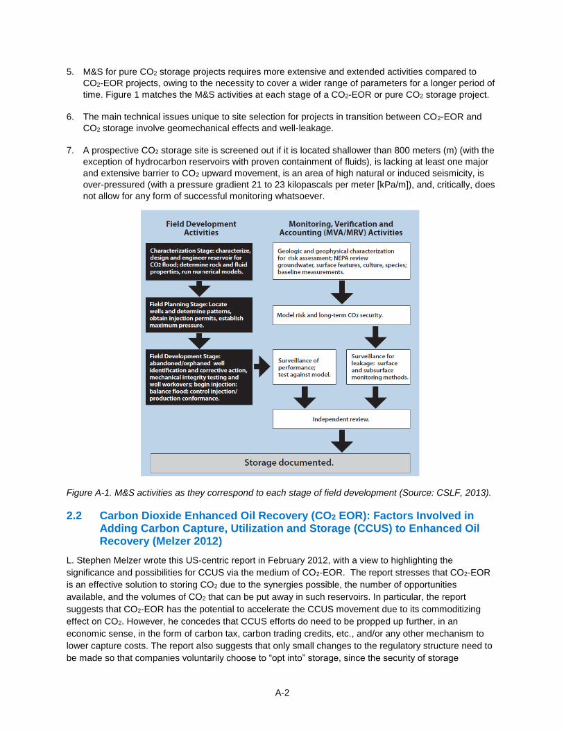
A-2
5. M&S for pure CO2 storage projects requires more extensive and extended activities compared to
CO2-EOR projects, owing to the necessity to cover a wider range of parameters for a longer period of
time. Figure 1 matches the M&S activities at each stage of a CO2-EOR or pure CO2 storage project.
6. The main technical issues unique to site selection for projects in transition between CO2-EOR and
CO2 storage involve geomechanical effects and well-leakage.
7. A prospective CO2 storage site is screened out if it is located shallower than 800 meters (m) (with the
exception of hydrocarbon reservoirs with proven containment of fluids), is lacking at least one major
and extensive barrier to CO2 upward movement, is an area of high natural or induced seismicity, is
over-pressured (with a pressure gradient 21 to 23 kilopascals per meter [kPa/m]), and, critically, does
not allow for any form of successful monitoring whatsoever.
Figure A-1. M&S activities as they correspond to each stage of field development (Source: CSLF, 2013).
2.2 Carbon Dioxide Enhanced Oil Recovery (CO2 EOR): Factors Involved in Adding Carbon Capture, Utilization and Storage (CCUS) to Enhanced Oil Recovery (Melzer 2012)
L. Stephen Melzer wrote this US-centric report in February 2012, with a view to highlighting the
significance and possibilities for CCUS via the medium of CO2-EOR. The report stresses that CO2-EOR
is an effective solution to storing CO2 due to the synergies possible, the number of opportunities
available, and the volumes of CO2 that can be put away in such reservoirs. In particular, the report
suggests that CO2-EOR has the potential to accelerate the CCUS movement due to its commoditizing
effect on CO2. However, he concedes that CCUS efforts do need to be propped up further, in an
economic sense, in the form of carbon tax, carbon trading credits, etc., and/or any other mechanism to
lower capture costs. The report also suggests that only small changes to the regulatory structure need to
be made so that companies voluntarily choose to “opt into” storage, since the security of storage
A-3
associated with injecting CO2 into EOR candidate sites (with an established hydrocarbon seal, by
definition) means that the regulatory structure that applies to EOR can be reused. The report
recommends setting up a framework for site-selective monitoring reporting requirements.
The Melzer report’s most salient findings are as follows:
1. CO2 flood surveillance needs and CCUS Monitoring Measurement and Verification needs are nearly
identical.
2. Companies can expect up to 90 to 95% of purchased CO2 to be stored in the reservoir through
incidental storage during typical closed-loop EOR operations. The appropriate metric to measure and
report storage is defined as:
3. There is tremendous synergistic opportunity between CCUS and CO2-EOR; however, for CCUS to
gain traction at a much higher pace, regulators must work to lower costs by: a) incentivizing CO2
capture companies via real-time capture credits, instead of at the end of EOR projects; b) raising
awareness among industries of the marketable value of their CO2 by-product; and c) not introducing
any new regulation/monitoring requirements for EOR projects claiming CO2 storage credit.
2.3 Geologic Carbon Storage through Enhanced Oil Recovery (Hill, Hovorka et al. 2013)
This 2013 paper, much like the CSLF report (CSLF, 2013), touches upon the various aspects associated
with CO2 storage in an EOR project, ranging from an overview of tertiary recovery in the United States to
CO2 supply-demand to CO2 transport pipelines. Of these topics, the most noteworthy discussions are
centered on the attractive potential for CO2 storage via residual oil zones (ROZs), the advantage EOR-
storage or CCUS has over pure storage.
The Hill et al. paper’s most salient findings are as follows:
1. The report suggests that if the residual oil saturation in the ROZ is at least 20%, it can be just as
successfully developed via EOR as the Main Pay Zones (MPZs), and so recommends deepening
existing wells in projects where this is deemed to be true (see Figure 2).
2. CO2-EOR is far more advantageous an option than pure CO2 storage for reasons such as decades of
operational experience; ability to assess storage capacity and injectivity with more certainty due to
availability of production and performance data; ability to manage the CO2 plume, etc. Table 1
summarizes the advantages of CO2-EOR compared to pure CO2 storage in saline aquifers.
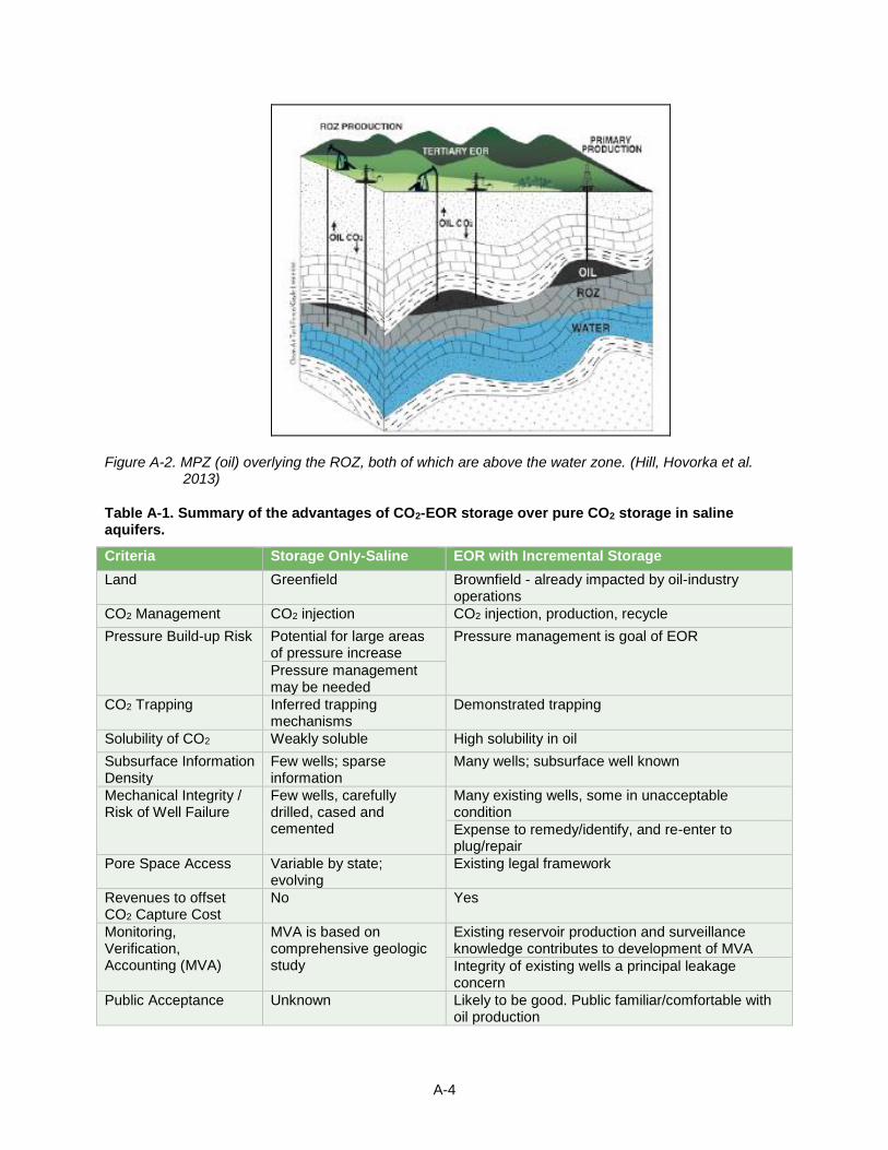
A-4
Figure A-2. MPZ (oil) overlying the ROZ, both of which are above the water zone. (Hill, Hovorka et al. 2013)
Table A-1. Summary of the advantages of CO2-EOR storage over pure CO2 storage in saline aquifers.
Criteria Storage Only-Saline EOR with Incremental Storage
Land Greenfield Brownfield - already impacted by oil-industry operations
CO2 Management CO2 injection CO2 injection, production, recycle
Pressure Build-up Risk Potential for large areas of pressure increase
Pressure management is goal of EOR
Pressure management may be needed
CO2 Trapping Inferred trapping mechanisms
Demonstrated trapping
Solubility of CO2 Weakly soluble High solubility in oil
Subsurface Information Density
Few wells; sparse information
Many wells; subsurface well known
Mechanical Integrity / Risk of Well Failure
Few wells, carefully drilled, cased and cemented
Many existing wells, some in unacceptable condition
Expense to remedy/identify, and re-enter to plug/repair
Pore Space Access Variable by state; evolving
Existing legal framework
Revenues to offset CO2 Capture Cost
No Yes
Monitoring, Verification, Accounting (MVA)
MVA is based on comprehensive geologic study
Existing reservoir production and surveillance knowledge contributes to development of MVA
Integrity of existing wells a principal leakage concern
Public Acceptance Unknown Likely to be good. Public familiar/comfortable with oil production
A-5
2.4 Optimization of CO2 Storage in CO2 Enhanced Oil Recovery Projects (Advanced Resources International (ARI) and Melzer Consulting 2010)
This 2010 study was performed with a view toward educating policymakers on the immense possibilities
and the potential environmental implications of CO2-EOR projects for CO2 storage. It strongly suggests
that resolving the uncertainty associated with regulatory and legal issues surrounding CCS/CO2-EOR is
worthwhile, chiefly because of the potential synergy that can occur between CCS and CO2-EOR
industries: oil production ensures the economic viability of CCS, while CCS can ensure a reliable and
affordable supply of CO2 for EOR operations.
This study’s most salient findings are as follows:
1. The report recommends applying next-generation CO2-EOR technologies, developing ROZs as
opposed to MPZs, and employing a variety of other increasingly ‘smarter’ methods.
2. The report highlights the immense commercial potential of ROZs, not only for oil but also for CO2
storage capacity.
3. “Next-generation” technologies include:
a. Isolating previously poorly swept reservoir intervals where CO2 can be injected in the future.
b. Optimally placing horizontal injection and production wells to target bypassed zones.
c. Optimizing the pattern-flood by improving well alignment and spacing, so as to integrate the
improved assessment of field behavior and geology.
d. Using physical materials or chemicals to divert and direct CO2 into poorly swept zones.
e. Adding polymers or other viscosity-enhancing chemicals to improve the mobility ratio between
injected fluid and oil and improve incremental oil recovery.
f. Extending the miscibility range by adding chemical agents.
4. Repressurizing using water or CO2 or skipping the waterflood altogether to implement CO2-EOR
earlier and produce better results. These three alternatives also store a greater amount of CO2 and
allow the operator to get credit earlier (Figure 3).
2.5 CO2-driven Enhanced Oil Recovery as a Stepping Stone to What? (Dooley, Dahowski et al. 2010)
This 2010 report for the US Department of Energy plays the role of devil’s advocate, written primarily to
promote the view that CO2-EOR is neither a sustainable means in itself nor the correct way forward to
achievable commercial deployment of CCS. The report cites two main arguments against using CO2-EOR
to make CCS more economically viable: first, the comparatively greater complexities associated with
EOR, and second, the poor economics of CO2 demand.
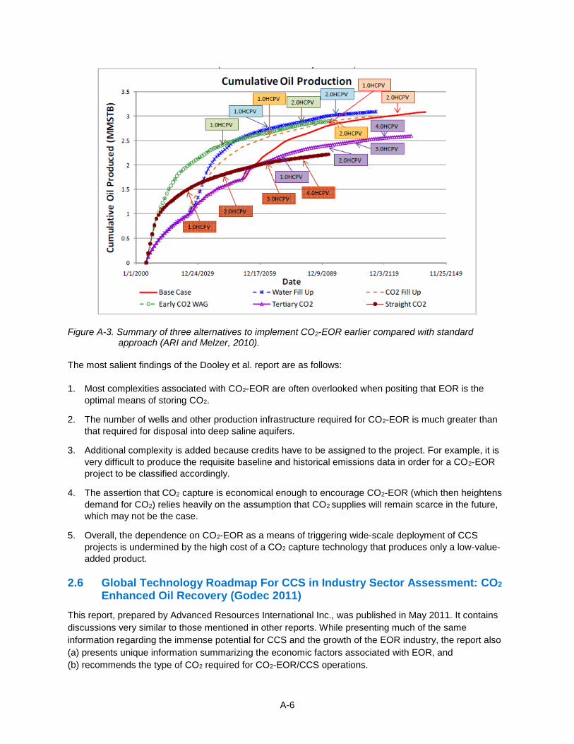
A-6
Figure A-3. Summary of three alternatives to implement CO2-EOR earlier compared with standard approach (ARI and Melzer, 2010).
The most salient findings of the Dooley et al. report are as follows:
1. Most complexities associated with CO2-EOR are often overlooked when positing that EOR is the
optimal means of storing CO2.
2. The number of wells and other production infrastructure required for CO2-EOR is much greater than
that required for disposal into deep saline aquifers.
3. Additional complexity is added because credits have to be assigned to the project. For example, it is
very difficult to produce the requisite baseline and historical emissions data in order for a CO2-EOR
project to be classified accordingly.
4. The assertion that CO2 capture is economical enough to encourage CO2-EOR (which then heightens
demand for CO2) relies heavily on the assumption that CO2 supplies will remain scarce in the future,
which may not be the case.
5. Overall, the dependence on CO2-EOR as a means of triggering wide-scale deployment of CCS
projects is undermined by the high cost of a CO2 capture technology that produces only a low-value-
added product.
2.6 Global Technology Roadmap For CCS in Industry Sector Assessment: CO2 Enhanced Oil Recovery (Godec 2011)
This report, prepared by Advanced Resources International Inc., was published in May 2011. It contains
discussions very similar to those mentioned in other reports. While presenting much of the same
information regarding the immense potential for CCS and the growth of the EOR industry, the report also
(a) presents unique information summarizing the economic factors associated with EOR, and
(b) recommends the type of CO2 required for CO2-EOR/CCS operations.
A-7
The most salient findings of this report are as follows:
1. CO2-EOR is a high capital-outlay venture; as a result, oil-prices have the greatest impact on the
economics of a project.
2. Expenditures associated with CO2 (natural or anthropogenic) are the single largest project expense
and can amount to nearly half the cost of revenue.
3. The two Mexican basins considered in particular suggest that an EOR recovery efficiency of around
20% is attainable, with around 0.32 tonnes of CO2 used for every barrel of incremental oil extracted.
4. For Villahermosa basin, the portion of CO2 for EOR purposes available from industrial sources within
a 100-kilometer (km) radius is estimated at a negligible 1%, while that for the Tampico-Misantla basin
is at a better (but still insufficient) 11% (Table 2).
5. Anthropogenic CO2 cannot be the only source to carry out a CO2-EOR operation; further investment
into transportation and capture infrastructure is required.
2.7 Modeling the Transition from Enhanced Oil Recovery to Geologic Carbon Sequestration (Bandza and Vajjhala 2014)
This paper, published in 2014 in Managerial and Decision Economics, presents a study conducted to
reveal the price-point combinations (global oil and CO2) at which four projects representing the spectrum
of pure EOR and pure CO2 storage - referred to as geologic storage (GS) – become economical for
widespread deployment (Table 3).
This paper’s most salient findings are as follows:
1. The price of CO2 alone cannot provide the desired financial impetus for wide-scale deployment of
pure CO2 operations.
2. Any future price rises in CO2 or CCS bonus’ that occur in the future will incentivize hybrid CO2-EOR.
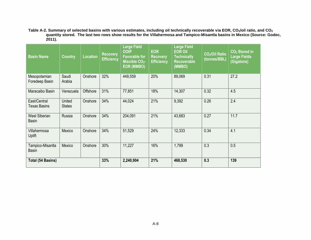
A-8
Table A-2. Summary of selected basins with various estimates, including oil technically recoverable via EOR, CO2/oil ratio, and CO2 quantity stored. The last two rows show results for the Villahermosa and Tampico-Misantla basins in Mexico (Source: Godec, 2011).
Basin Name Country Location Recovery Efficiency
Large Field OOIP Favorable for Miscible CO2-EOR (MMBO)
EOR Recovery Efficiency
Large Field EOR Oil Technically Recoverable (MMBO)
CO2/Oil Ratio (tonnes/BBL)
CO2 Stored in Large Fields (Gigatons)
Mesopotamian Foredeep Basin
Saudi Arabia
Onshore 32% 449,559 20% 89,069 0.31 27.2
Maracaibo Basin Venezuela Offshore 31% 77,851 18% 14,307 0.32 4.5
East/Central Texas Basins
United States
Onshore 34% 44,024 21% 9,392 0.26 2.4
West Siberian Basin
Russia Onshore 34% 204,091 21% 43,683 0.27 11.7
Villahermosa Uplift
Mexico Onshore 34% 51,529 24% 12,333 0.34 4.1
Tampico-Misantla Basin
Mexico Onshore 30% 11,227 16% 1,799 0.3 0.5
Total (54 Basins) 33% 2,240,904 21% 468,530 0.3 139
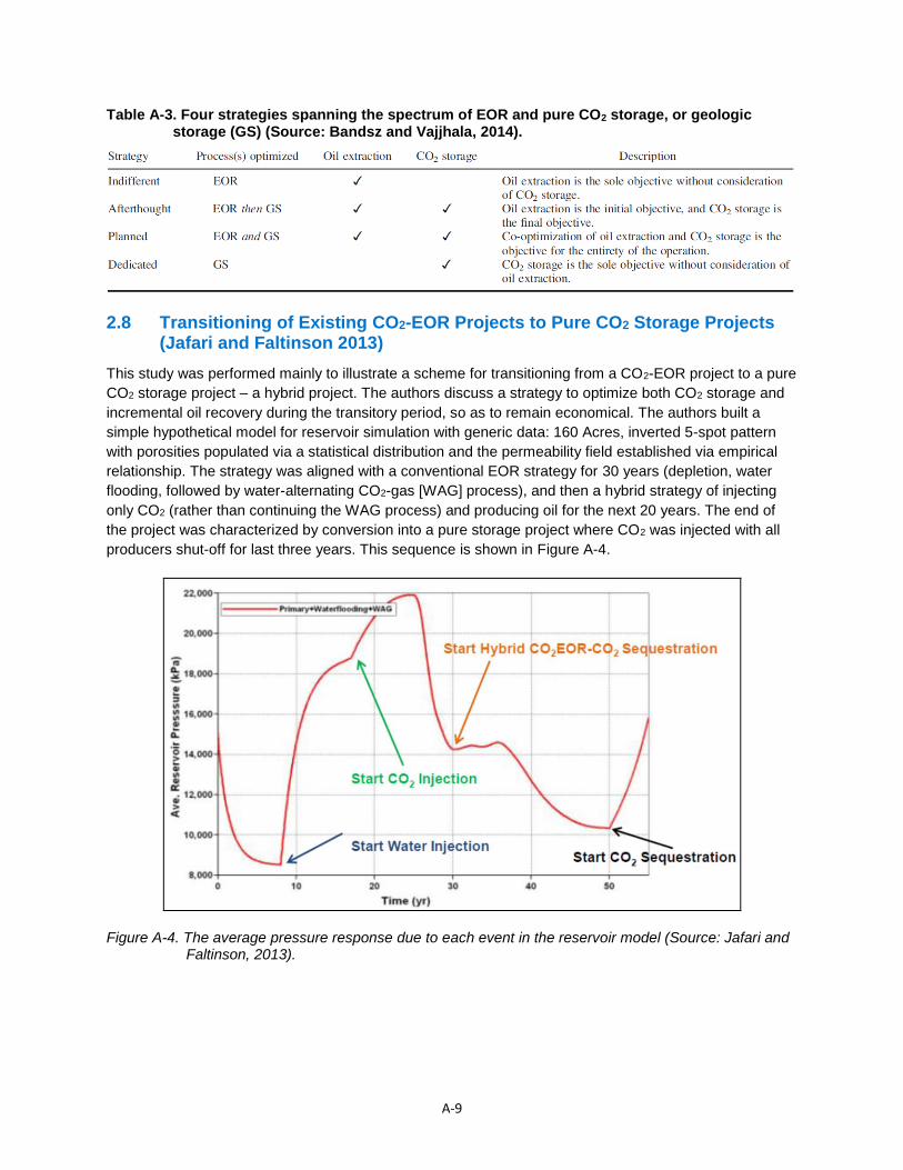
A-9
Table A-3. Four strategies spanning the spectrum of EOR and pure CO2 storage, or geologic storage (GS) (Source: Bandsz and Vajjhala, 2014).
2.8 Transitioning of Existing CO2-EOR Projects to Pure CO2 Storage Projects (Jafari and Faltinson 2013)
This study was performed mainly to illustrate a scheme for transitioning from a CO2-EOR project to a pure
CO2 storage project – a hybrid project. The authors discuss a strategy to optimize both CO2 storage and
incremental oil recovery during the transitory period, so as to remain economical. The authors built a
simple hypothetical model for reservoir simulation with generic data: 160 Acres, inverted 5-spot pattern
with porosities populated via a statistical distribution and the permeability field established via empirical
relationship. The strategy was aligned with a conventional EOR strategy for 30 years (depletion, water
flooding, followed by water-alternating CO2-gas [WAG] process), and then a hybrid strategy of injecting
only CO2 (rather than continuing the WAG process) and producing oil for the next 20 years. The end of
the project was characterized by conversion into a pure storage project where CO2 was injected with all
producers shut-off for last three years. This sequence is shown in Figure A-4.
Figure A-4. The average pressure response due to each event in the reservoir model (Source: Jafari and Faltinson, 2013).
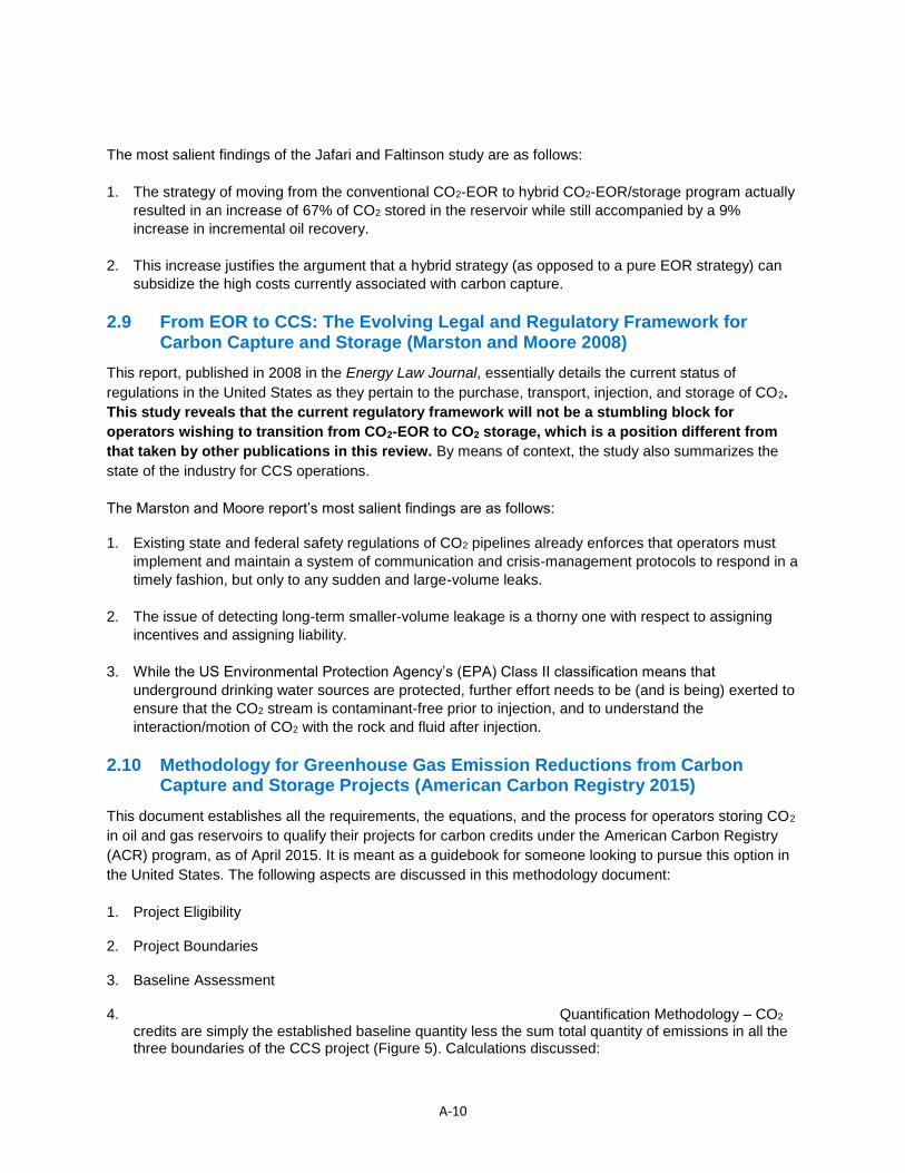
A-10
The most salient findings of the Jafari and Faltinson study are as follows:
1. The strategy of moving from the conventional CO2-EOR to hybrid CO2-EOR/storage program actually
resulted in an increase of 67% of CO2 stored in the reservoir while still accompanied by a 9%
increase in incremental oil recovery.
2. This increase justifies the argument that a hybrid strategy (as opposed to a pure EOR strategy) can
subsidize the high costs currently associated with carbon capture.
2.9 From EOR to CCS: The Evolving Legal and Regulatory Framework for Carbon Capture and Storage (Marston and Moore 2008)
This report, published in 2008 in the Energy Law Journal, essentially details the current status of
regulations in the United States as they pertain to the purchase, transport, injection, and storage of CO2.
This study reveals that the current regulatory framework will not be a stumbling block for
operators wishing to transition from CO2-EOR to CO2 storage, which is a position different from
that taken by other publications in this review. By means of context, the study also summarizes the
state of the industry for CCS operations.
The Marston and Moore report’s most salient findings are as follows:
1. Existing state and federal safety regulations of CO2 pipelines already enforces that operators must
implement and maintain a system of communication and crisis-management protocols to respond in a
timely fashion, but only to any sudden and large-volume leaks.
2. The issue of detecting long-term smaller-volume leakage is a thorny one with respect to assigning
incentives and assigning liability.
3. While the US Environmental Protection Agency’s (EPA) Class II classification means that
underground drinking water sources are protected, further effort needs to be (and is being) exerted to
ensure that the CO2 stream is contaminant-free prior to injection, and to understand the
interaction/motion of CO2 with the rock and fluid after injection.
2.10 Methodology for Greenhouse Gas Emission Reductions from Carbon Capture and Storage Projects (American Carbon Registry 2015)
This document establishes all the requirements, the equations, and the process for operators storing CO2
in oil and gas reservoirs to qualify their projects for carbon credits under the American Carbon Registry
(ACR) program, as of April 2015. It is meant as a guidebook for someone looking to pursue this option in
the United States. The following aspects are discussed in this methodology document:
1. Project Eligibility
2. Project Boundaries
3. Baseline Assessment
4. Quantification Methodology – CO2 credits are simply the established baseline quantity less the sum total quantity of emissions in all the three boundaries of the CCS project (Figure 5). Calculations discussed:
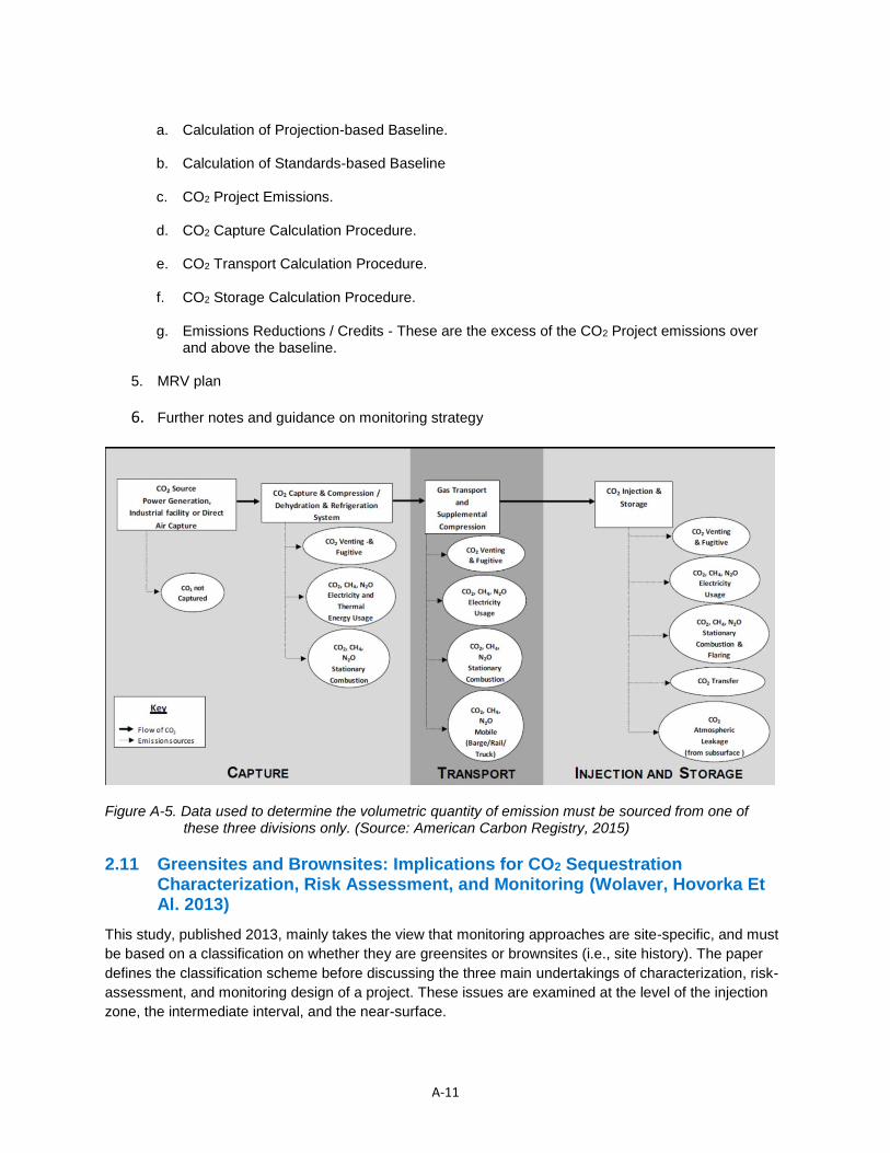
A-11
a. Calculation of Projection-based Baseline.
b. Calculation of Standards-based Baseline
c. CO2 Project Emissions.
d. CO2 Capture Calculation Procedure.
e. CO2 Transport Calculation Procedure.
f. CO2 Storage Calculation Procedure.
g. Emissions Reductions / Credits - These are the excess of the CO2 Project emissions over
and above the baseline.
5. MRV plan
6. Further notes and guidance on monitoring strategy
Figure A-5. Data used to determine the volumetric quantity of emission must be sourced from one of these three divisions only. (Source: American Carbon Registry, 2015)
2.11 Greensites and Brownsites: Implications for CO2 Sequestration Characterization, Risk Assessment, and Monitoring (Wolaver, Hovorka Et Al. 2013)
This study, published 2013, mainly takes the view that monitoring approaches are site-specific, and must
be based on a classification on whether they are greensites or brownsites (i.e., site history). The paper
defines the classification scheme before discussing the three main undertakings of characterization, risk-
assessment, and monitoring design of a project. These issues are examined at the level of the injection
zone, the intermediate interval, and the near-surface.
A-12
This study’s most salient findings are as follows:
1. Typically, brownfields refer to areas that have had previous significant surface industrial or
commercial use, while greenfields refer to undeveloped areas. The authors extend this idea to
development of the subsurface in defining greensites and brownsites, for the selection of EOR or
CCS activities. The factors influencing the development of greensites and brownsites are shown in
Figure 6 and Table 4.
2. The authors suggest classifying sites into one of these two categories to simplify the process of
devising an effective monitoring strategy. A summary of these differences, in terms of
characterization, risk assessment, and monitoring design are provided for the three zones of interest
(from the injection zone, intermediate zone, to the near surface) in Table 5 through Table 7.
Figure A-6. Classification of potential EOR or storage reservoirs into either greensites or brownsites (Source: Wolaver et al., 2013).
Table A-4. The main factors behind site development (Source: Wolaver, Hill et al., 2013).
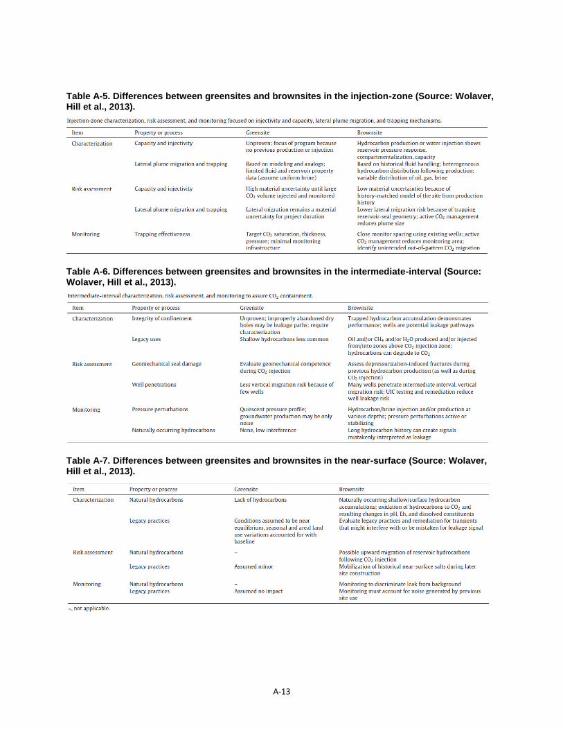
A-13
Table A-5. Differences between greensites and brownsites in the injection-zone (Source: Wolaver, Hill et al., 2013).
Table A-6. Differences between greensites and brownsites in the intermediate-interval (Source: Wolaver, Hill et al., 2013).
Table A-7. Differences between greensites and brownsites in the near-surface (Source: Wolaver, Hill et al., 2013).
A-14
3. Overall, greensites require greater effort in the characterization phase, to demonstrate capacity,
injectivity, and long-term storage integrity. Following this characterization, risk assessment must be
performed to highlight the major sources of practical uncertainty, with monitoring being designed
around counteracting these risks. For greensites, the undisturbed pore fluids offer uncertainties
associated with locating the CO2 plume and an unproven seal.
4. For brownsites, on the other hand, the risks (and subsequently the monitoring) are centered around
high well density and legacy wells providing potential leakage pathways for CO2, out-of-pattern
migration of CO2, and undetected damage to geologic seal quality as a result of development
activities.
2.12 Draft Underground Injection Control (UIC) Program Guidance on Transitioning Class II Wells to Class VI Wells. (Office of Water, US Environmental Protection Agency, December 2013)
This document, like the earlier ACR document discussed, is designed as a detailed set of guidelines for
wells that US operators want to be permitted as a geologic sequestration well (Class VI) rather than a
typical injection well (Class II). It is intended to be a “go-to” reference for wells that are currently Class II to
qualify and obtain a Class VI permit. All regulations are intended to protect consumers under the Safe
Drinking Water Act (SDWA). The reader is encouraged to refer to Section 4 of the document for all the
specifics needed to obtain permitting as a Class VI.
2.13 General Technical Support Document for Injection And Geologic Sequestration Of Carbon Dioxide: Subparts RR and UU Greenhouse Gas Reporting Program (Office of Air and Radiation, US Environmental Protection Agency, November 2010)
This technical support document offers illustrative examples for complying with the minimum
requirements indicated by the US EPA regulations under Greenhouse gas reporting rule – Subpart RR
and UU under the Clean Air Act. Key points to note are as follows:
1. Companies can choose to opt in for more detailed reporting (subpart RR rule) or keep with a simple
mass balance (CO2in – CO2out) reporting (subpart UU).
2. To get credits, companies will need to report under the RR. For example, currently the Internal
Revenue Service (IRS) has tax credits for CO2-EOR (~$10/tonne). These credits are tied to more
detailed RR reporting. Similarly, credits for CO2 reduction under Clean Power Plan (111-B) would be
tied to RR.
3. The level of effort is based on the risk and assessment of leakage pathways. Typical
monitoring/modeling by EOR operators will be enough in many cases for RR reporting; however, if
there is perceived risk from leakage pathways (such as faults, wells, etc.), then a more detailed plan
should be submitted and executed. The MRV plan can include mechanical integrity testing, well
surveys, and surface leakage monitoring.
A-15
3. References
Advanced Resources International, I. and Melzer Consulting (2010). Optimization of CO2 Storage In CO2 Enhanced Oil Recovery Projects.
American Carbon Registry (2015). Methodology for Greenhouse Gas Emission Reduction from Carbon Capture and Storage Projects.
Bandza, A. J. and S. P. Vajjhala (2014). "Modeling the Transition from Enhanced Oil Recovery to Geologic Carbon Sequestration." Managerial and Decision Economics 35(1): 20-35.
CSLF (Carbon Sequestration Leadership Forum). 2013. Final Report by the CSLF Task Force on Technical Challenges in the Conversion of CO2-EOR Projects to CO2 Storage Projects.
Dooley, J., R. Dahowski, et al. (2010). "CO2-driven Enhanced Oil Recovery as a Stepping Stone to What?" DOE, julio.
Godec, M. L. (2011). "Global technology roadmap for CCS in industry sectoral assessment CO2 enhanced oil recovery." Prepared by Advanced Resources International, Inc. for United Nations Industrial Development Organization, Arlington, VA, USA.
Hill, B., S. Hovorka, et al. (2013). "Geologic carbon storage through enhanced oil recovery." Energy Procedia 37: 6808-6830.
Jafari, A. and J. Faltinson (2013). Transitioning of existing CO2-EOR projects to pure CO2 storage projects. SPE Unconventional Resources Conference Canada, Society of Petroleum Engineers.
Marston, P. M. and P. A. Moore (2008). "From EOR to CCS: the evolving legal and regulatory framework for carbon capture and storage." Energy LJ 29: 421.
Melzer, L. S. (2012). "Carbon dioxide enhanced oil recovery (CO 2 EOR): Factors involved in adding carbon capture, utilization and storage (CCUS) to enhanced oil recovery." Center for Climate and Energy Solutions.
USEPA. (2010). General Technical Support Document for Injection and Geologic Sequestration Of Carbon Dioxide: Subparts RR and UU Greenhouse Gas Reporting Program. Office of Air and Radiation.
USEPA. (2013). Geologic Sequestration of Carbon Dioxide: Draft Underground Injection Control (UIC) Program Class VI Well Testing and Monitoring Guidance (EPA 816-R-13-004)
Wolaver, B. D., S. D. Hovorka, et al. (2013). "Greensites and brownsites: Implications for CO 2 sequestration characterization, risk assessment, and monitoring." International Journal of Greenhouse Gas Control 19: 49-62.