Embed Size (px)
Citation preview
REPORT No. 324
FLIGHT TESTS ON U.S. S. LOS ANGELES
PART I–FULL SCALE PRESSURE DISTRIBUTION
INVESTIGATION
By S. J. DE FRANCE
Langley MemoriaI Aeronautical Laboratory
449

REPORT No. 324
FLIGHT TESTS ON U. S. S. LOS ANGELES
PART I–FULL SCALE PRESSURE DISTRIBUTION IWESTIGATION
By S. J. DE I?SANCE
SUMMARY
The investigation reported hrein uw conducted ?iyt7Milational Adohow Committeefor Aero-nautics at the request of and in conjunction un”ththe Bureau of Aeronautics; Na~y Department.The purpose uxrs ~“marily to 06tain cw”multaneougdata on the loada and stresses expem”encedin
$ight by the V. S. S. La Angeles, which could be u8eil in rigid airship struciure design. A second-ary object of the inresiigah”on was to determine tlie turning and drag characterish”mof the airdiip.T%estress investigation UW8conducted by the .NaayDepartment.
T7te aerodynamic loading was oMained Zy measun”ng the pressure at 96 locations on tle tat7surfaces, 64 on the hull, and 6 on tfie passenger car. These measurement~ were made during aseries of rnaneuws cmwisting of turw and rerer8als in 8?noothair and dum”nga cTui8e in roughair which wasjust short of squall propofi”one.
Tle results of the pressure measurement k the Ml indicate that tileforc# cm tlieforeibdyof an airship are relathely smalL The ta27surface measurements show conckm”rely that tie forcescaused by gusts are much greater tfian the caused by iiorizmdal maneurei-8. In this investigationthe taZ surface loadings cawed by gusts closely approached the designed loads of tfie tail structure.
Tle turning and drag characteristic WZZbe reported in separate papers.
INTRODUCTION
Since the design data for rigid airships is still largely empirical, it is obvious that as muohadditional information as is poasible should be obtained from each new design. One of thegreatest deficiencies in design data is that concerning the forces imposed upon an airship byvarious maneuvers and by gusts, especially the Iat.ter. ‘iVlth this in mind, the Bureau ofAeronautics, h’a~ Department, inatitutd”an elaborate series of twk on the U. S. S. LM Angelesfor the purpose of determining g the aerodparnic loads, their distribution, end the reauItingstresses in cert sin structural members of the airship. As a secondary object of this investigation,data -were to be obtained from which the turning characteristics of the ship couId be determined.
The work was ditided into two parts. The Bureau of Aeronautics, Navy Department,conducted the stress in=rastigation and the National Advisory Committee for Aeronauticsobtained the aerodpamic load distribution and turning data. AU of the data obtained byboth agencies were taken simultaneously and the records were synchronized. It is the purposeof this report to present the result-s of that part of the in-instigation which was conducted bythe hTational Advisory CommittW for Aeronautics.
ProbabIy the best way of obtaining the aerodyntic forces acting on an airship is by thedetermination of fulhcale pressure distribution. Such investigations on rigid airships to date-have been limited to the British tests on the l?%? (reference 1), R+% (reference 2), and theR-38 (reference 3), and to an investigation made in Germany on the LZ–i26 (the present U. S. S.Los Angeles), the results of which have not been published. In this country previous airshippressure distribution investigations have been confined to the research on a nonrigid type,the G7 (reference 4.
451
—
-———
..-
.—
452 REPORT NAh?IONAL ADVISORY COMMEU’IX FOR AER~NJ$uTIcS .—
With the exception of the tests on the R-M and Gl”, all of these investigations have con-sisted of measuring the pressures at comparatively few points. In the investigation herekdescribed the pressures were measured at 95 points on the tail surfaces, 54 on the forward portionof the hull, and 5 on. the passenger car. The pressures at- these locations were recorded duringturning maneuvers and while the ship was encountering gush..
APPARATUS AND INSTALLATION
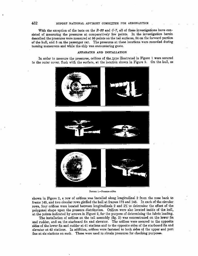
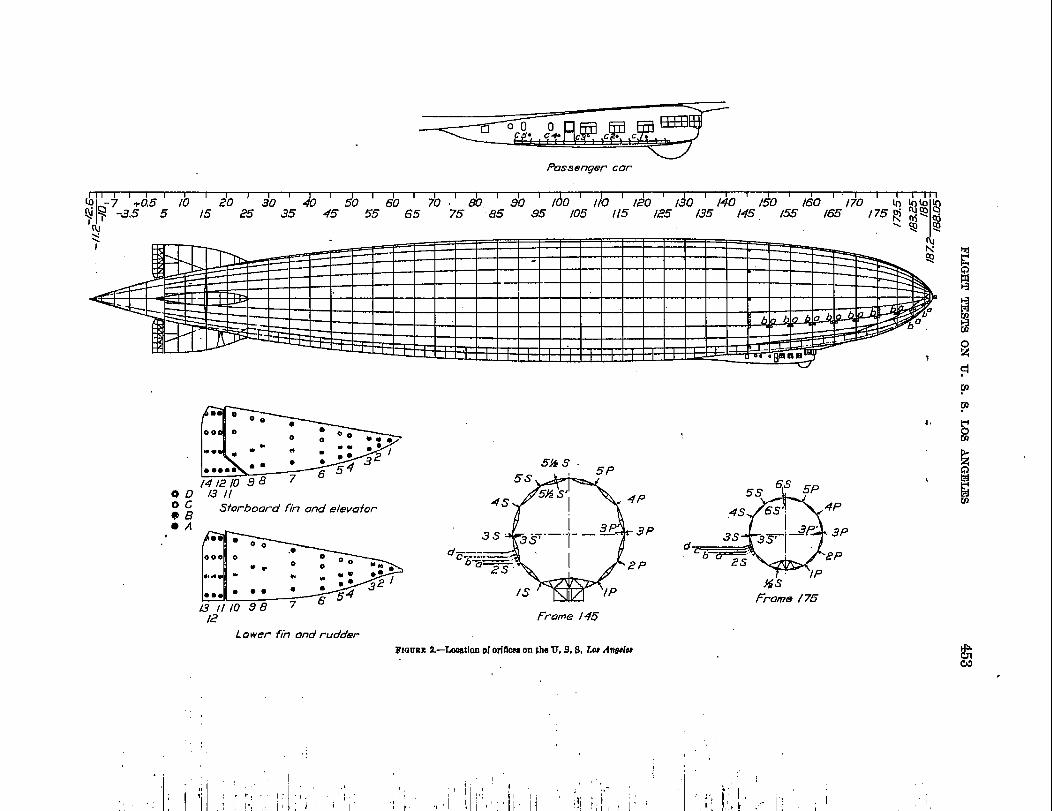
In order to measure the pressures, orifices of the_ @pe illustrated in Figure 1 were securedto the outer cover, flush with the surface, at the location shown in Figure 2. On the hull, as
FIQUBE l.—Prcwrre orSfka
shown in Figure 2, a row of orifices ,was installed along longitu@nal 2 from the nose back taframe 146, rind two circular rows girdled the hull at frames 175 and 145. In each of the circularIIOWS, four orifices were located betwem longitud~~ 2 and 2X to deterfine the effect of thepolygonal shape upon the pressure distribution. Orifices were also located inside of the hull,at the points indicated by arrows in Figure 2, for the purpose of determining the fabric loading.
The installation of orifices on the tail msembly (fig. 2) was Wncentrated on the lower fin
and rudder, and on the starboard fin and elevator. The orifices were secured to the oppositesides of the lower fin and rudder at 41 stations and to the opposite sidee of the starboard fln andelevator at 42 stations. In addition, orifices were faitened to both sides of the upper and portfins at six stations on each. These were used to .obt.ain pressures for checking purposes.
.C
Passenger car
I I I I I I I I I
-7 +0s5 10 20 ‘ 30 40I I I I
doI
doI
+0 T h, ‘ 3b Iho 1)0I I I I I I I 1 I I I I I I I I I
$ ~ -3,5 5 15 25 35 45 55 65 75 85 .95120 /3’0 f40 f50 160 ‘ “/7!0
!
g g)/05 115 /25 /35 /45 155 165 /75; % @
‘m ~q Q
WOL7 /311
Sforboord fin ondelevafor;S
f.
4s
dc—---—— “’b~~
2s
/s
Frame 145
Lower fin andrucfder
F1OUREa.–k-mtim oforiflocaon tho U, 9,8, LwAngeha
6S 5P
4
5s .
.4s 6S’. 4P
3s ~y 2P’ 3Pd- ~.
b% 2P1P
%sFromw /75
g
#
,: ,“
454 REPORT NATIONAL M)VISORY COMMT?ITIE FOR AERONAUTICS
To determine the fln effect of the passenger cm, five orifices were secured to each side ofthis body at the locations shown in Figure 2.
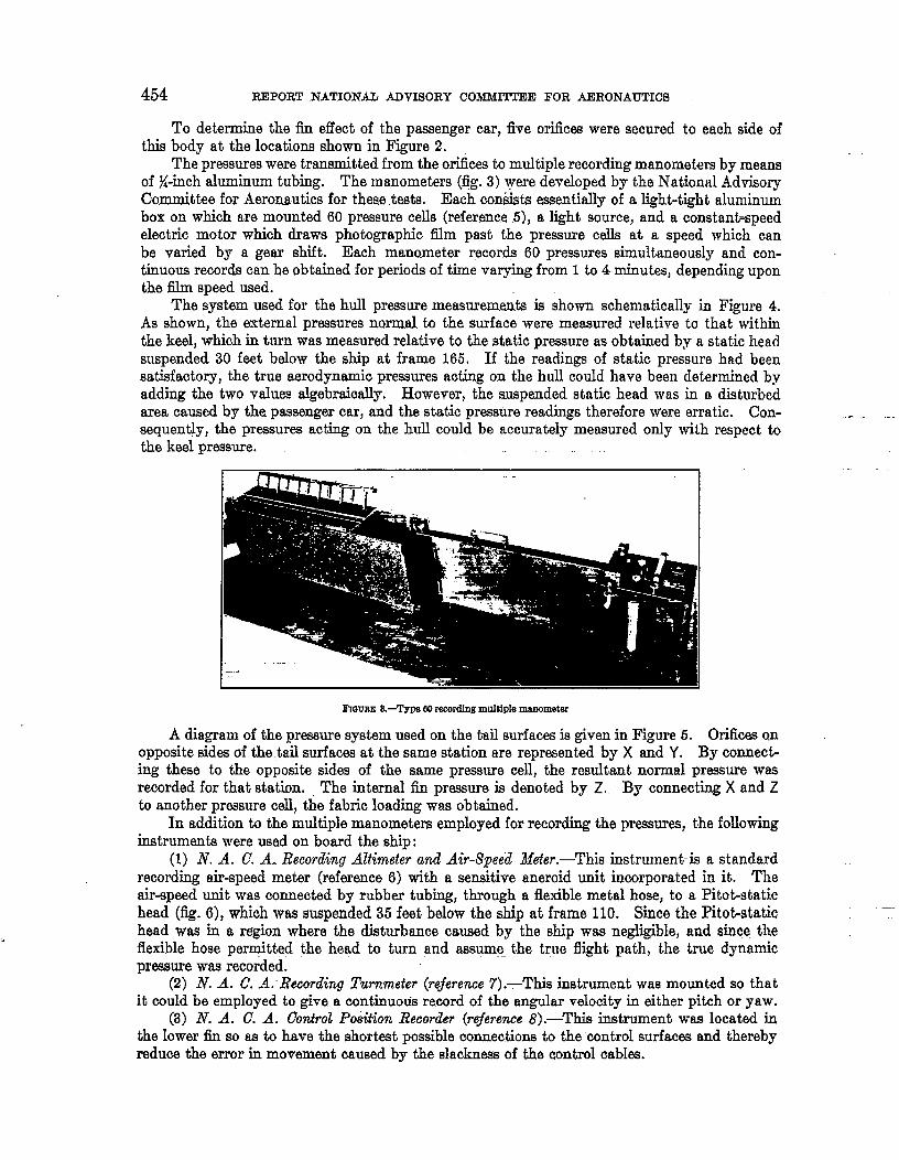
The pressures were transmitted from the orifices to multiple recording manometers by meansof %-inch aluminum tubing. The manometers (fig. 3) were developed by the National AdvisoryCommittee for Aeronautics for these tests. Each consists essentially of a light-tight aluminumbox on which are mounted 60 pressure cells (reference 5), a light source, and a constant-speedelectric motor which draws photographic film past the pressure cells at a speed which canbe varied by a gear shift. Each manometer records 60 pressures simultaneously and con-tinuous records can be obtained for periods of time varying from 1 to 4 minutes, depending uponthe tllm speed used.
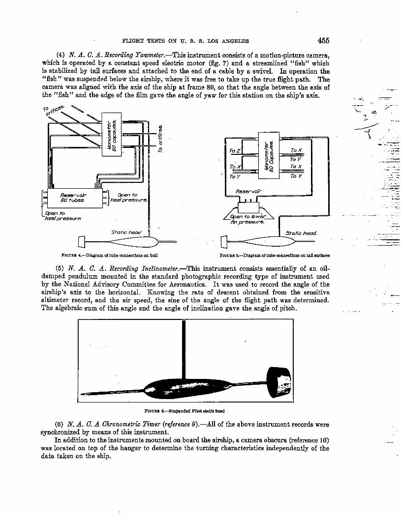
The system used for the hull pressure measureme& is show-n schematicaHy in Figure 4.As shown, the external pressures normal to the surface were measured relative to that withinthe keel, which in turn was measured relative to the static pressure as obtained by a static headsuspended 30 feet below the ship at frame 165. If the readings of static pressure h~d beensatisfactory, the true aerodynamic pressures acting on the hull could have been determined byadding the two vahms algebraically. However, the suspended static head was in a disturbedarea caused by the passenger car, and the static pressure readings therefore were erratic. Con- . -.sequently, the pressures acting on the hull could be accurately measured only with respect tothe ksal pressure.
Frmma S.-Type WIrecmdlng multiple manometer
A diagram of the Pressure system used on the tail surfaces is given in Fkure 5. Orilictx+Qn
opposite s[des of the t&l surfac~ at the same station are represen~d by X a;d Y. By connect-ing these to the opposite. sides of the same pressure cell, the resultant normal pressure wasrecorded for that station. , The internal fin pressure is denoted by Z. By connecting X and Zto another pressure cell, the fabric loading was obtained.
In addition to the multiple manometers employed for recording the pressures, the followinginstruments were used on board the ship:
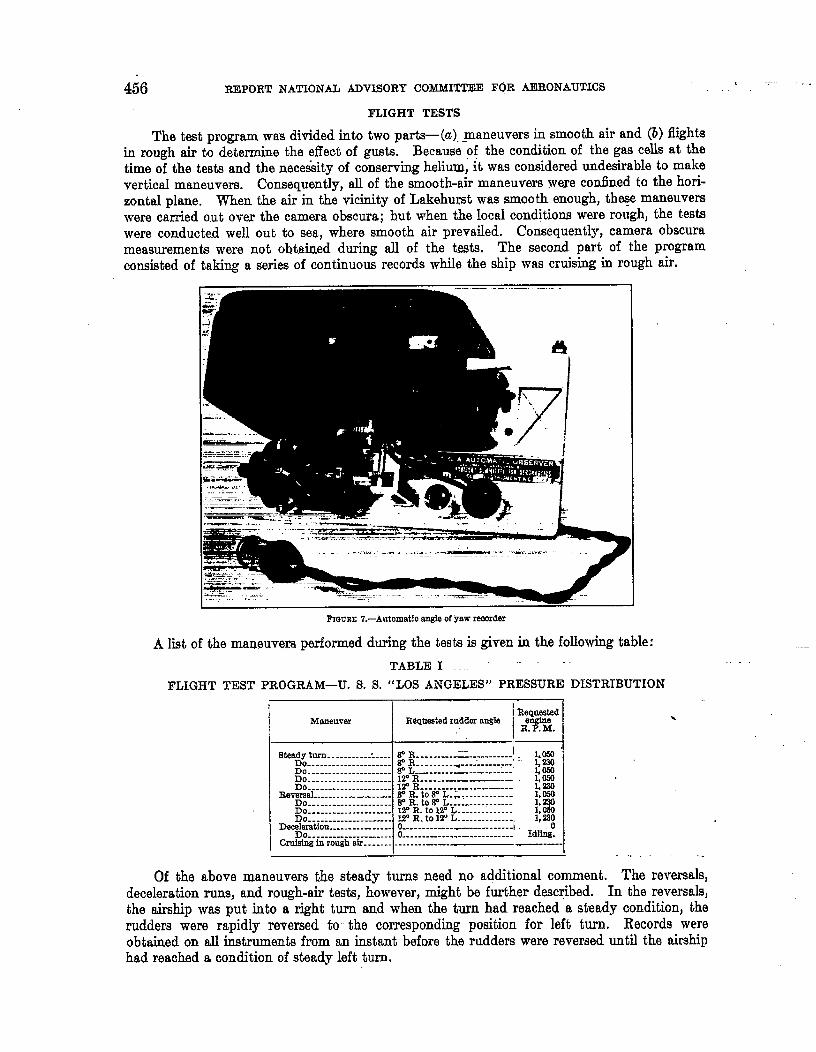
(1) N. A. C. A. Recording Altimeter and Air-Speed Meter.—This instrument-is a standardrecording air-speed meter (reference 6) with a sensitive aneroid unit incorporated in it. Theair-speed unit was connected by rubber tubing, through a flexible metal hose, to a Pitot-statichead (fig. 6), which was suspended 35 feet below the ship at frame 110. Since the Pltot-statichead was in a region where the disturbance caused by the ship was negligible, and since theffexible hose pernjtted the head to turn and assume the truo flight path, the true dynamicpressure was recorded.
(2) N. A. C. A. Recordiw Turnmeter (rejerence 7ji-This instrument “was mounted so thatit could be employed to give a continuotis reem-d of the angular velocity in either pitch or yaw.
(~) N. A. C. A. Conirol Poiition Recorder (reference 8).—This instrument was located inthe lower fin so as to have the shortest possible connections to the control surfaces and therebyreduce the error in movement caused by the slacknms of the control cabks.
FLI(3HT TESTS O?J U. S. S. MM A.?.?GETiES 455
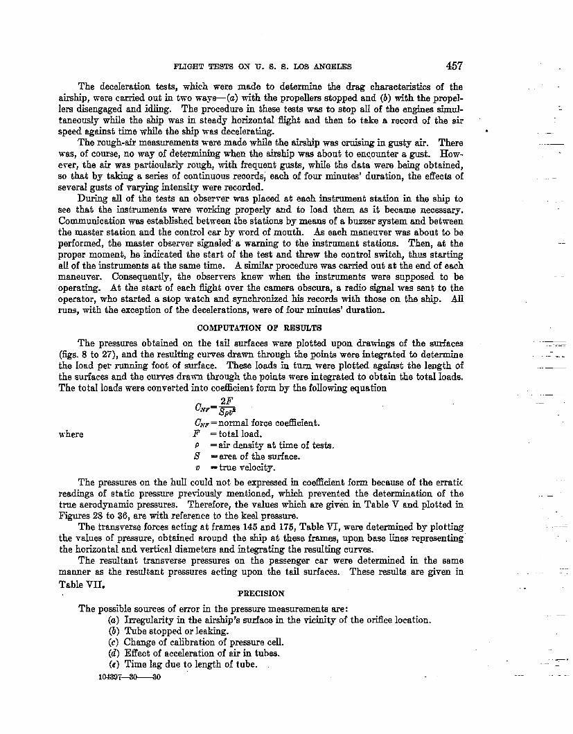
(4) N. A. C. A.. Recording Ywnneter.-Tbis instient consists of a motion-picture camera,which is operated by a constant speed eleotric motor (J&. 7) and a streamlined “fish” whichis stabilized by tail surfaces and attached to the end of a cable by a swivel. In operation the“fish” was suspended below the airship, -where it was free to take up the true flight path. Thecamera was aligned with the a.xi.sof the ship at frame 80, so that the angle between the axis ofthe “fish” and the edge of the film gave th; angle of yaw for this statio~ on the ship’s axis.
/
r-o z+&To Y To Y
—
—
. < “-- ---
< ,“\ ::” ---------- ...-*....-
--- ...-.=..._ k
_.~=
...’: &-..-, .”. ----.,—.,’*---- .-. . -.G
—.-—.
—-— ---—-——
FmL,BX4.—Diagram of tube ooomectlon.qon MU FrGrEE 5.-DIagiam 0[ tub+ connection on M mrfaces
(5) N. A. C. A. Recording Inclinometer.—This instrument consists essentially of an oil-damped pendulum momted in the stamdard photographic recording type of instrument usedby the NationaI Advisory Committee for Aeronautics. It was used to record the angle of theairship’s axis ta the horizontal. II&oviing the rate of descent obtained from the sensitivesItimeter record, and the air speed, the sine of the angle of the fight path was determined.
.—
The algebraic mm of th~ angle and the angle of inclination gave the angle of pitch.—-. .—
.-
.
~GVBE 6.-S-ded Pitot Adio bead
(6) N. A. 0. A G%ronornetti Timer (referenee 9). —AU of the abo~e instrument records weresyncbrorizecl by me- of this instrument.
In addition to the inst-rumenti mounted on board the airship, a camera obsara (reference 10)was located on top of the hangar to det ermine the turning characteristics independently of t-hedata taken on the ship.
-—
456 REPORT NATIONAL ADVISORY COMMIT1’EE F6R AERONAUTICS. .
FLIGHT TESTS
The ted program was divided into two pa~(a). maneuvers fi smooth air and ~) flightsin rough air to determine the effect of gusts. Because of the condition of the gas cells at thetime of the tests and the nece&ity of conserving helium, it was considered undesirable to makeverticaI maneuvers. Conwquently, all of the smooth-air maneuvers were cofined to the hori-zontal plane. When the air in the vicinity of Lakehurst was smooth enough, the% maneuverswere carried out over the camera obscura; but when the local conditions were rough, the testswere conductad well out to sea, where smooth air pr?vafled. Co~equentlYl camera obscma.measurements were not obtained during all of the tests. The second part of the programconsisted of taking a series of continuous records while the ship was cruising in rough air.
—-.=. ,....—--—.- ,—_
.----------- .,. ,.J.. .-—4+ .-’ ,.i->-. ..-c.+.-4+’ ,. -.
.*7&—_, “?. -– -.J_uc,, ? . .
---%+_ .. . ___
FIQWEE7.—Automat!o ro@e of Yaw remrder
A list of the maneuvers performed during the tests is given in the following table:
TABLE I ““ ““
FLIGHT TEST PROGRAM-U. S. S. “LOS ANGELES” PRESSURE DISTR1BUTION
I!Ileqawted
Moneumr RI?QtI&sWdrudder angleI R%?%
k
1steadytorn. . ..- ....~.... V R-.-. -.--. -----. --....! LIMO
Do-------------------- W R . . . ..--. %... -------- ly230Do --------------- W L_— . . . . . ..-. -_- .. . . ...” L O@)Do . . . . . . . . . . . . . . . . . . . W R.----.-——--– 1,050Do------------------ 1P R . . . . . .._L..-..__--— 1.‘MI
Eevwsel...- . . . ..-—-—- ~ IL tow L.”, ------------- 1,~Do----------------- V R. to P L._–--- . . . . .Do-------------------- I%R. toW L . . . . . . . . . ----- ?%Do . . . . ..-.. --.----—.. W’ R. to 12’ L . . . . ---------- 1:230
mmtloR . . . .. . . . . . . . ..- o- . . . . .. —..__ ------Do . . . . . . . ----------- 0-. . . . ------------------- ‘ Idling:
Cruising In rough nir------- .-- . . . ..—–. —- —--. .
Of the above maneuvers the steady turns need no additional comment. The reversals,deceleration runs, and rough-air tests, however, might be further described. In the reversals,the airship was put into a right turn and when the turn had reached a staady condition, therudders were rapidly reversed to the corresponding position for left turn. Records wereobtained on all instruments from an instant before t4e rudders were reversed until the airshiphad reached a condition of steady left turn.
FLJGHT TESTS
The deceleration tests, which were
ON U. S. S. LOS ANGELES
made to determine the -
457
characteristics of theairship, were cmried out in “two ways—(a) with the propellers stopped&d (b) with the propel-lers disengaged and idling. The procedure in these tests was to stop aU of the engines si&ul-taneoudy while the ship was in steady horizontal flight and then b take a record of the airspeed against time while the ship was decekrating.
The rough-air measurements were made -while the airship was cruising in gusty air. Therewas, of course, no way of determining when the airship was about to encounter a gust. How-ever, the air was particukdy rough, with frequent gusts, whiIe the data were being obtained,so that by taking a series of continuous records, each of four minutes’ duration, the effects ofseveral gusts of mqying intensity were recorded.
During all of the tats au observer was placed at each imtrument station in the ship tosee that the instruments were working properly aud to load them as it became neowsary.Communication was established between the stations by means of a buzzer system and bet-iveenthe master station aud the control car by word of mouth. As each maneuver was about to beperformed, the inter observer signaled’ a warning to the instrument stations. Then, at theproper moment, he indicated the start of the test and threw the control switch, thus startingdl of the instruments at the same time. A similar procedure was carried out at the end of eachmaneuver. Consequently, the obserrers knew when the instmments were supposed to beoperating. At the start of each tlight over the camera obscura, a radio signal was sent to theoperator, who started a stop watch and synchronized his records with those on the ship. AUruns, with the exception of the decelerations, were of four minutw’ duration.
COMPUTATION OF RESULTS
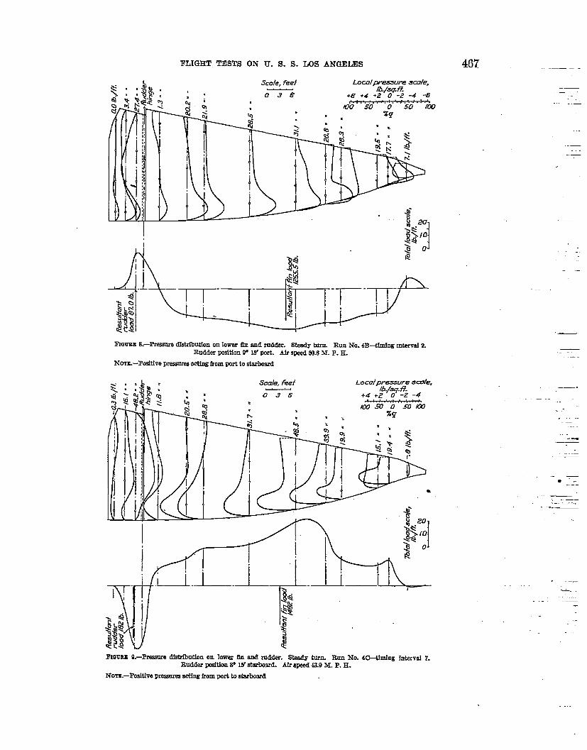
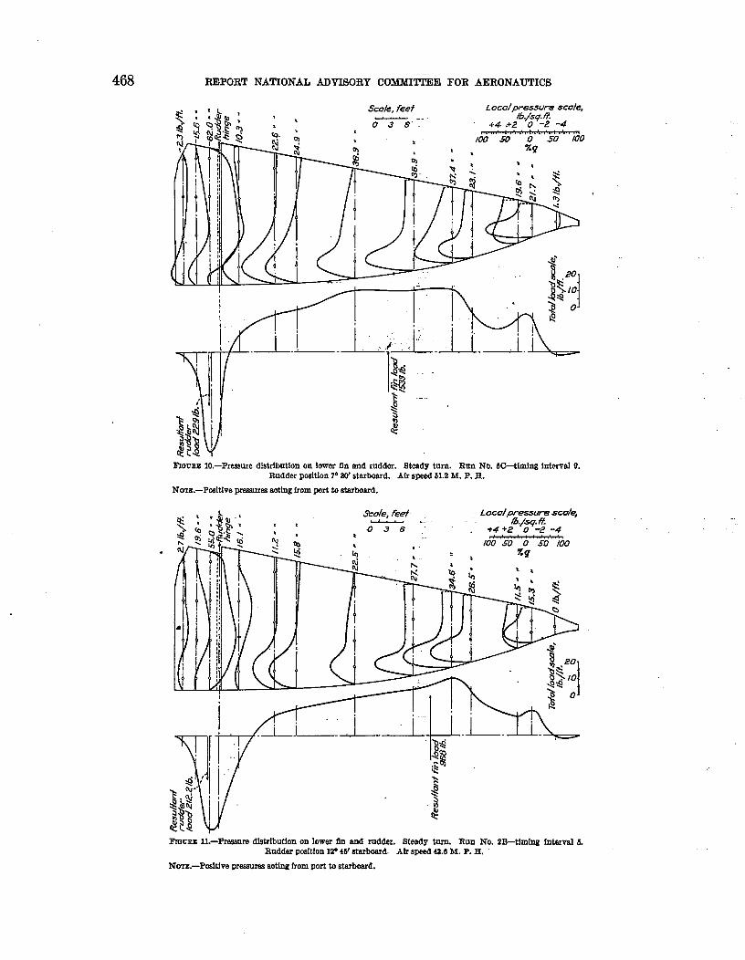
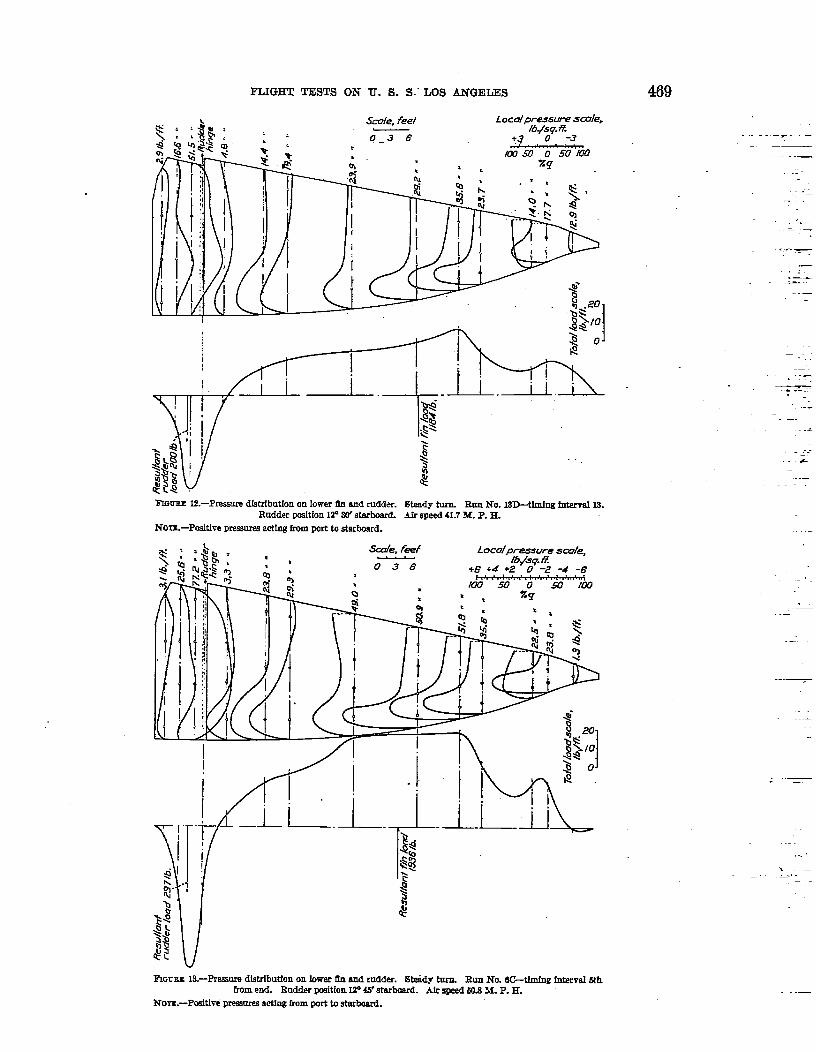
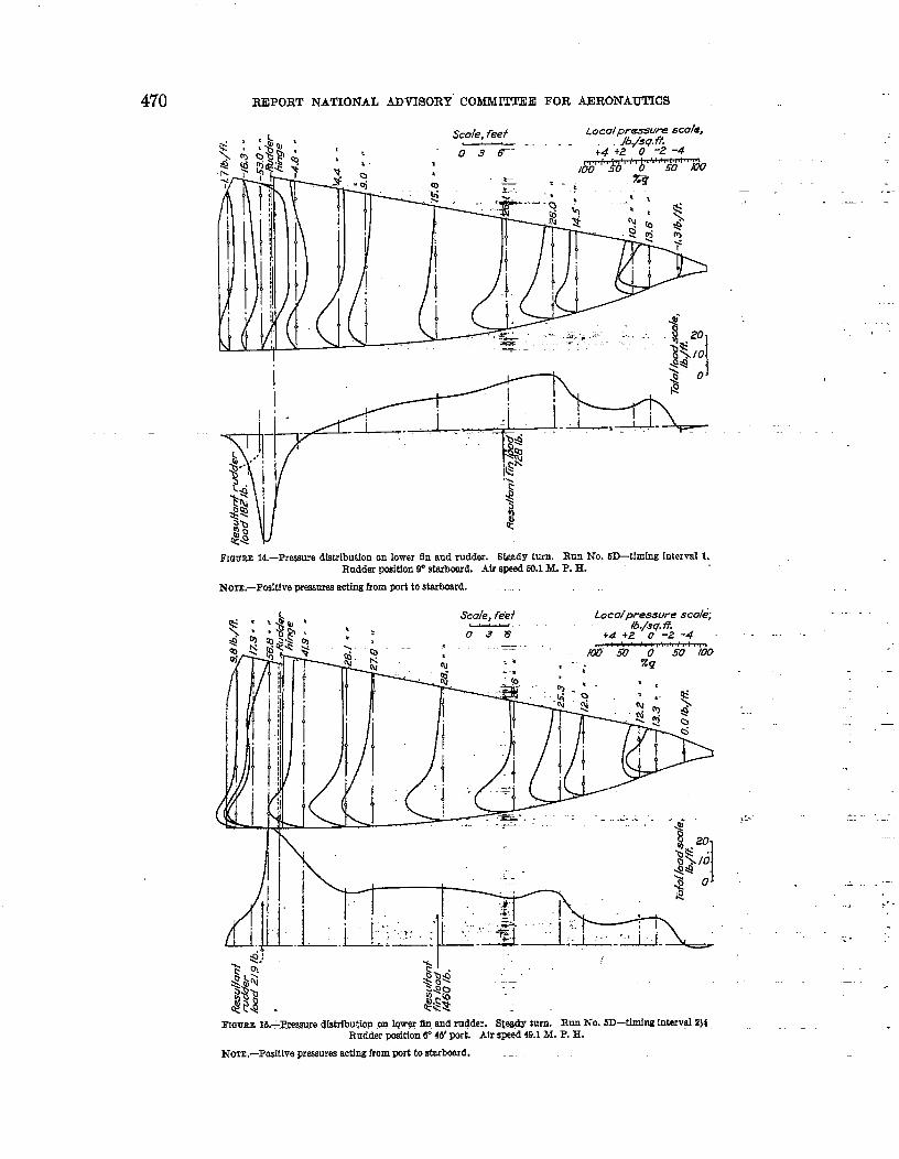
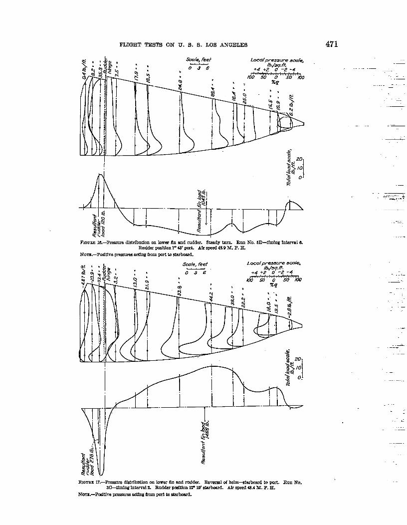
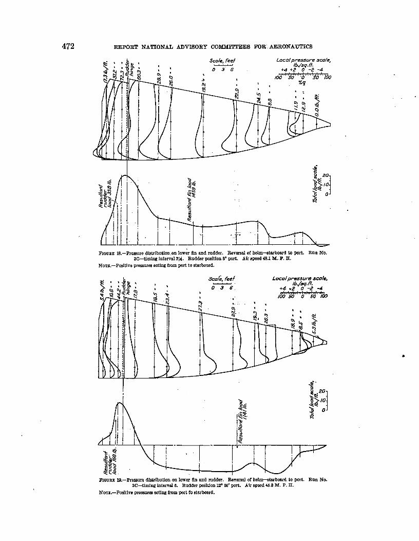
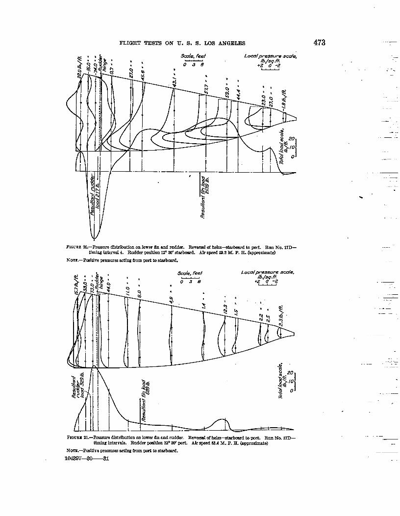
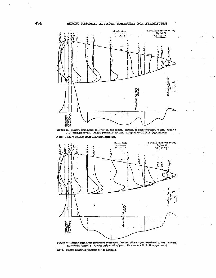
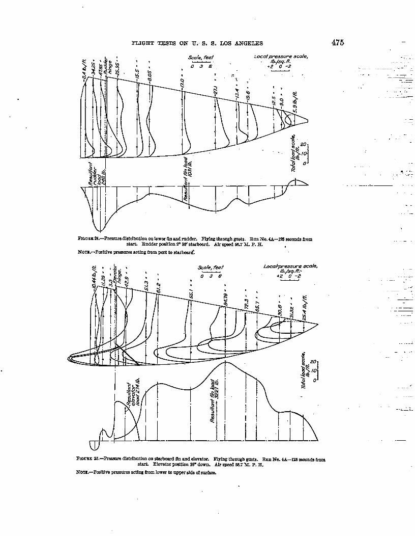
The pressures obtained on the tail surfaces were plotted upon &-swings of the surfaces(figs. 8 to 27), and the resulting curves drawn through the points were integrated to determinethe load per running foot of surface. These loads in turn were pIotted against the length ofthe surfaces and the curves drawn through the points were integrated to obtain the total loads.The total loads were converted into coefficient form by the folIowing equation
C~~=normaI force coe%hient.where F’ = total load.
P = air density at time of tests.S = area of the surface.Q = true velocity.
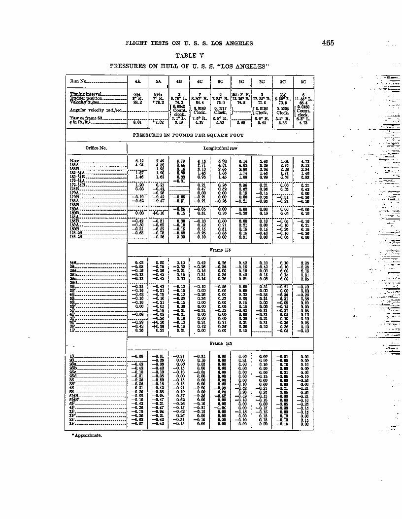
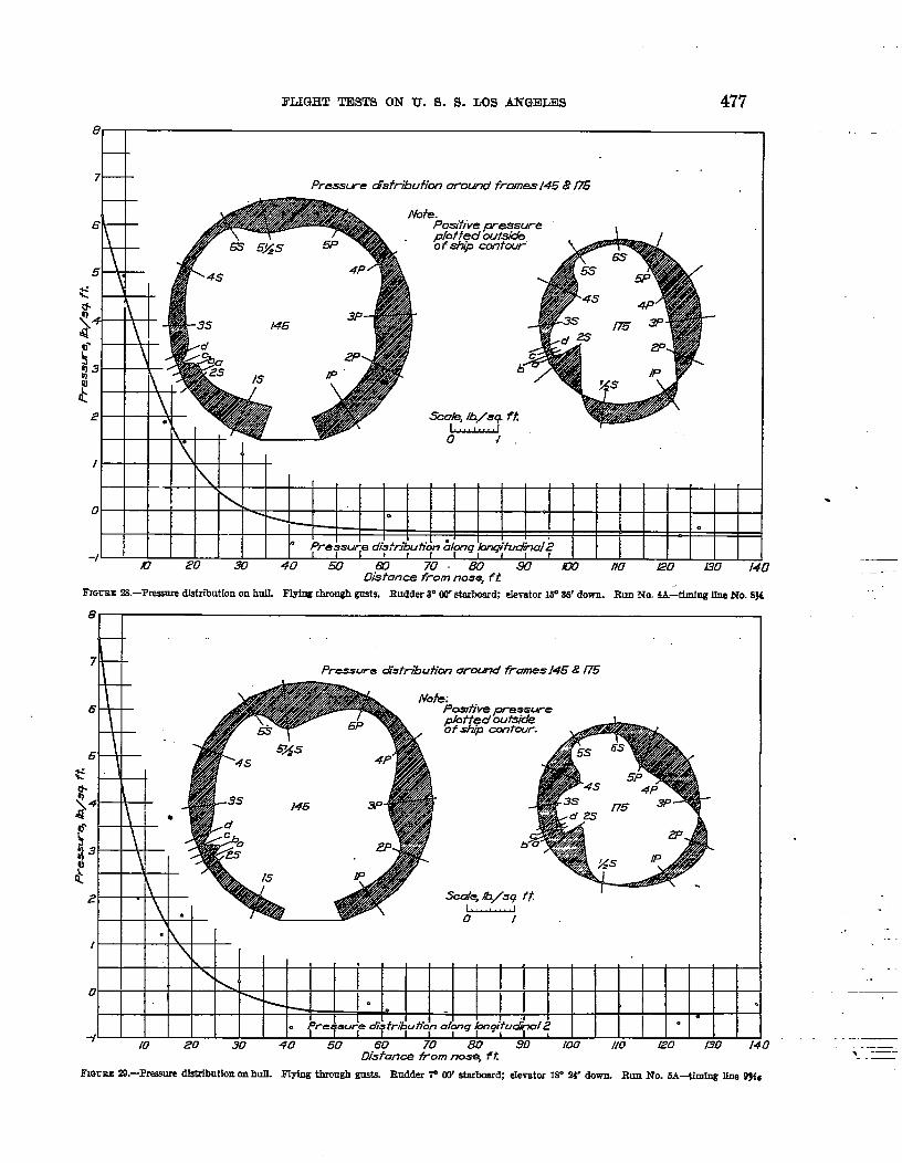
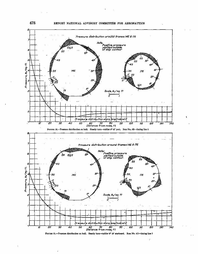
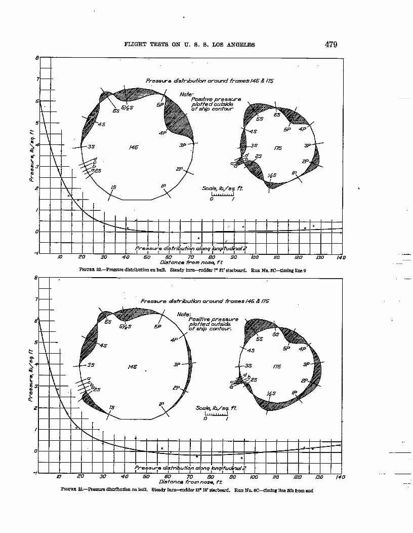
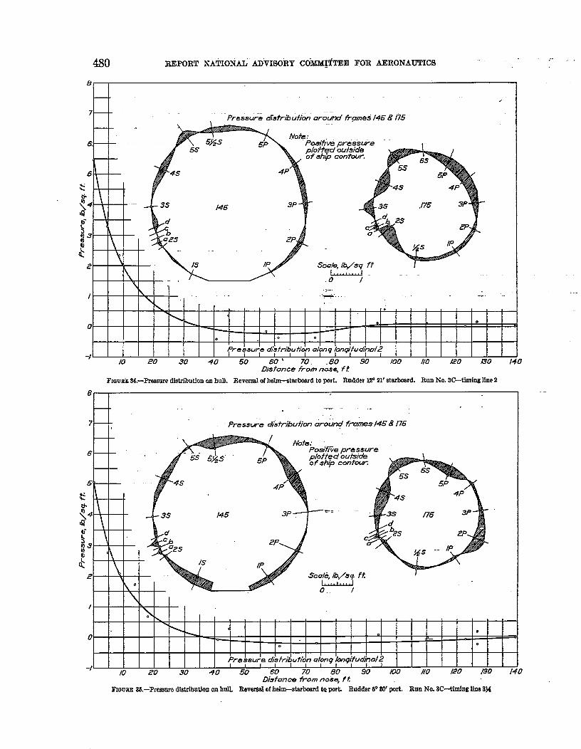
The pressures on the hulI could not be expressed in coefficient form because of the erraticreadings of static pressure preciously mentioned, which prevented the determination of thetrue aerodynamic pressures. Therefore, the values which are givtin in Table V and plotted inFigures 2S to 36, are with reference to the keel pressure.
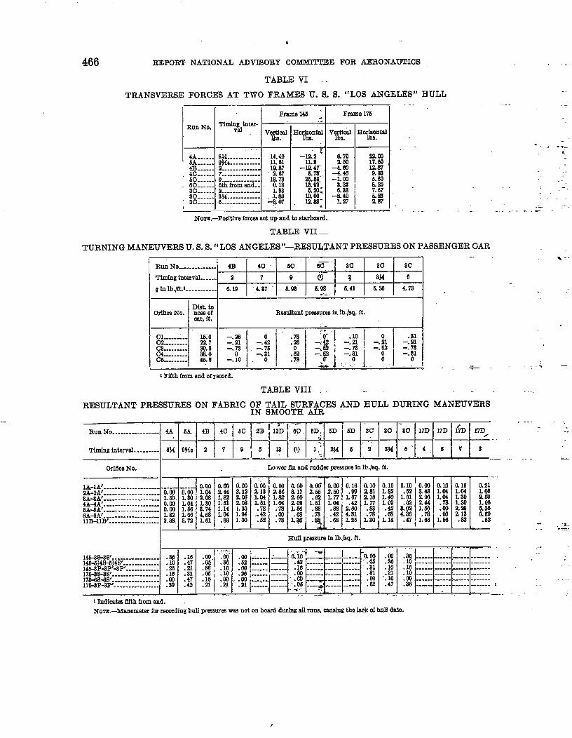
The transverse forces acting at frames 145 and 175, Table VI, were determined by plottingthe vahs of pr-ure, obtained mound the ship at these frames, upon base lines representingthe horizontal and vertical diameters and integrating the resulting curves.
The resuItant transverse pressures on the passenger car were determined in the samemanner as the resultant pressures acting upon the taiI surfaces. These results are given in
Table VII.PRECISION
The possible sources of error in the pressure measurements are:(a) Irregularity in the airship’s surfam in the vicinity of the orifice location.(b) Tube stopped or leaking.(c) Change of calibration of pressure ceIL(d) Effect of acceleration of air in tubes.(e) Time lag due to length of tube.
10439i~
--
* —
—
.—.-.
-—----.
—
.- —
458 REPORT NATiONAL ADVISORY COMMITTEES FOR AERONAUTICS.-
The error due .to (a) was negligible, since all of the ofices were located within 18 inches ,from a girder where.. the tru8 ehapp of the ship was n@nta$ed and” the fabric was taut. Thepossibility of error due to (b) was removed, since the.tubing was inspected after each flight andthe data which were obtained from defective tubes. w?rg deleted. A clamping device wasattached to each manometer which permitted the clamping off of all of the tubes leading to the
.—
orifices and the opening of tubes leading from a rese~oir to the, pressure cells. With the aid ofa U-tube manometer which was connected to the rea&voir, calibrations were made of all of themultiple recording manometers after each flight. Thge was a_slight change (c) in the calibra- “tion of the pressure cells dufig the tests, and this could account for a maximum error of + 2 percent in the pressures.
The effect of acceleration. of the air in the tubes@) was dirninated in the td surface pres-sures, since only resultant pressures were measured SKLdthe tubes from the orifices on each sideof the surface ran parallel toeach other from the surfac& to the manometer. In the hull pressureinddation, where the normal hull pressures were measured with respect to the keel pressures,there is a possibility of some error being introduced ig the longer tubes. However, the manom-eter was centrally located so that the average length. of tube %s about 50 feet and the onlyappreciable error wouId be in the measurements fro~ the nose ofic~ where the tuber~ngth ..-reached 100 feet. The probable error in the measure~nts from these long tubes is + 1 per cent.The error due to time lag in tubing (e) is negligible, since it has been proven by tests (reference11) that lag iu )&inch tubing for 100-foot length? is too small to m&sure, and in no part of theinstallation did the length of an individual tube tx~ceed this “value. Consequently, it is safe tosay that the tail surface pressure measurements are .D~t ~ error .by more than + 2 per cent andthe hull pressures by not more than * 3 per cent.
The greatest error in the results is due to. the .fFa@ingof the curves through the points of - .,plotted pressures The fairing of these cur& coUld. .Cause a maximum error in the total loadsof * 5 per cent,
. .
DISCUSSION OF BE$ULTSTAIL SURFACE RESULTS
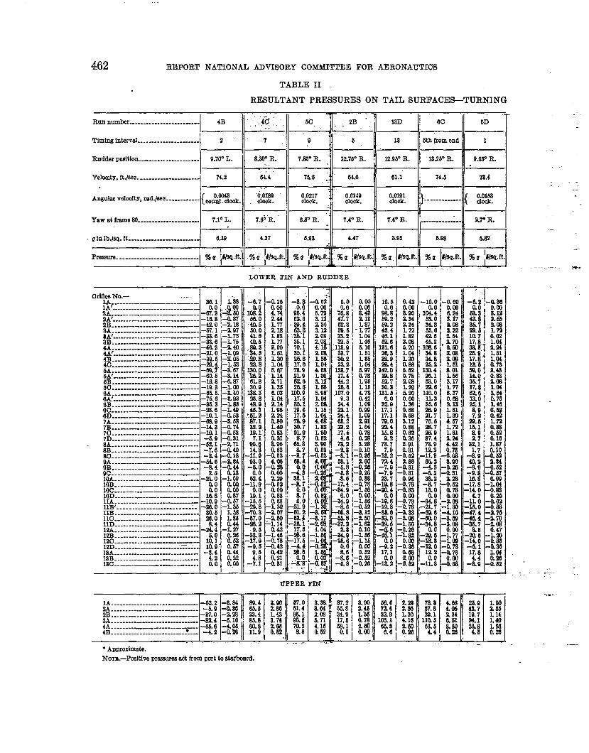
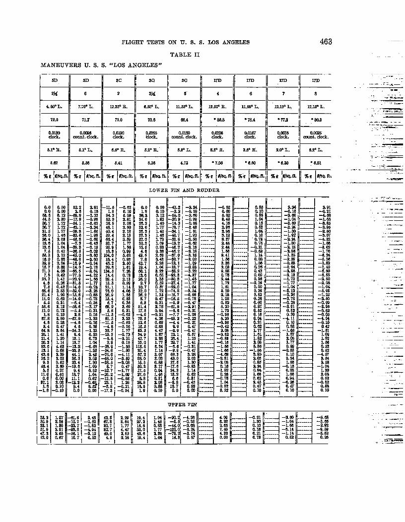
The results are presented in tqbular and curve fo_gn. The maximum pressures recorded forthe vertical tail surfaces during turning maneuvem are given in Table H and are presented graphi-cally in Figures 8 to 23. It will be observed that during all of the maneuvers there was a concen-tration of pressure in a vortex area along the leading edge of the fin. In several cases theselocal resultant pressures, w“hich were the average of the vortex fluctuations, exceeded 100 percent Qat points 4A and 5A on the lower fin, and in one case, run Number 13D, a vslue of 1.43 qwas reached. These pressures were large but localized, so that the total loads on each surfacewere never excessive.
.
The maximum fin load encountered during the turning maneuvers in tiooth air was 2,139pounds. In Table IV this load is reported as having been encountered by the surface duringa reversal. Actually, it occurred while the @ship was in a right turn, since the ruddera had notbeen reversed at the time that the record waa obtaiq~d.. Unfo@uqately, the normal force coeffi-cient could not be positively determined for this load, because the air-speed recorder failed andonly an approximate value of the dynamic head could be obttied... The approximate head was1.53 inches of water and the corresponding normal force coallicient was 0.253. This value wasexceeded in two of the steady turns at alower speed. The maximum normal force coefficientfor a k alone during the smooth-air maneuve~ w= 0.320, This occurrred during a steadyturn at a speed of 64.4 feet-per second with rudder 8.3° to starboard and resulted from a loadof Ody 1,482”pouti-ds.
The maximum norrmd force caeffi”&nt for the fidder aIone and also the maximum over-allnormal force cotint for the fln and rudder combined, resulting from the turning maneuvers,occurred during a reversal of the hebn. In this. rn~euver, run Number 3C, the rudders w&ereversed from 12.35° right to 11,55° left in 9 secon&, while the airship was making a speed of71 feet per second. The resulting ccdkients were 0.323 for the rudder and 0.268 for therudder and fln together.
FLJGHT TESTS ON U. S. S. LOS ANGELES 459
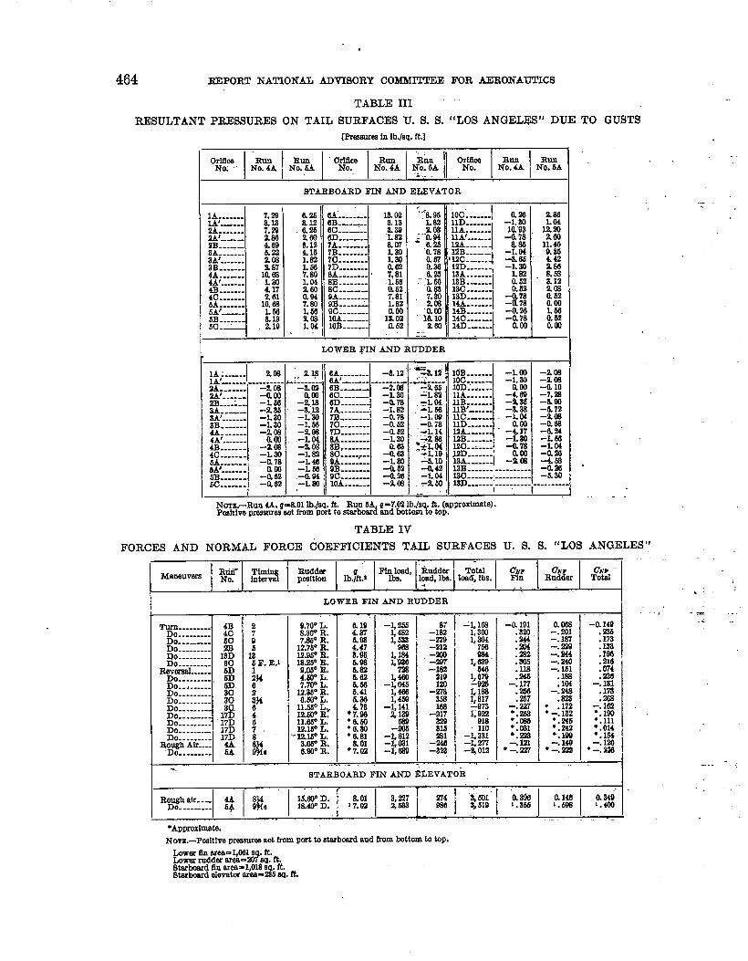
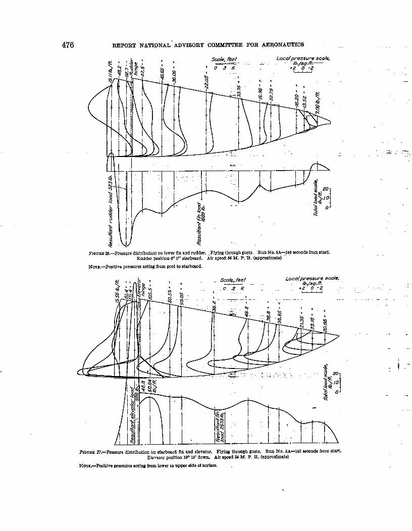
WhiIe flying through gusts, the local pressures and the t&d loads encountered by the tailsurfaces greatly exceeded the ~alues obtained during horizontal maneu~era in smooth air.The pressures caused by two gusts are gi-ien in Table III and gaphicaIly represented in I?iguree24 to 27. OnIy the rwdt-s of two gusts We given, but these represent the largest loads encount-ered during 10 runs of appro.xirnately four minutes each, which were made during an elapsedtime of four hours. Considering that all of these runs were made in rough air which was justshort of squall proportions, the redts of these two runs indicate the dangerous ~oadings thatmight be expected in a storm.
Considering the totaI loads and normal force coticients in Table IV, iti can be seen that thegreat-t effect of the gust9 was in a ~mtical direction. The -h Angeles was designed to with-stand a force equivalent to a normal force coefficient of 0.34 ainmhanemdy on each set of taflsurfaces. In run Number 4A, the normal force coefficient for the horizontal surfaces was 0.349, “but that for the vertical surfaces at the same instant was only 0.126. Consequently, thedesign loading was approached but not exceeded even though. the vertical loadiug was large.In run h’umber 5A, the design Jimit for the taiI surface loading was more closely approached.Unfortunately the air-speed recorder faded during this run, so that onIy an approximate. valueof the dynamic head could be determined. Consequently the normal force coefficients may bein error, but by not more than 10 per cent. AIIowing for this possible error, the normal forcecoefficient for the starboard & and elevator is stilI Iargej and combining this with the normalforce coefficient for the vertical surfaces, the resultant closely approaches the design value.
HULL AND PASSENGEE CAS RESULTS
The investigation of the hull pressures was not as successful as that of the tail surfaces.The traihg head, from which the static pressure refmmce for alI of the hdl preesurea wasobtained, was not suspended far enough from the keel at frame 165 h be outside of the disturb-ance caused by the passenger car. Consequently the pressures given in Table V and repre-sented graphically @ Figures 28 to 36 are given with respect to the keel pressure, It might bementioned, though, that by checking the nose pressure, obtained in this marmer, against theair speed head it was found that there was never a discrepancy of more than 8 per cent, andtherefore it is probable that the values of pressure given with respect to the keel pressure arewithin 8 per cent of the true aerodynamic pressure.
The error in the true aerodynamic pressure data did not affect the determination of thetransverse forces at frames 145 and 175, since these forces mere obtained by integrating theresultant pressure curves and, consequently, the effect of the static pressure was eliminated.The transverse forces for thwe two rings are recorded in Table VI. & can be seen, thwe wasonly one smooth-air maneuver that caused a sizable force. This was a steady turn, run Number5C, and even in this case the force at frame 175 was small. The force at frame 145 might havebeen caused by a localized lateral gust. The forces obtained during the rough-air flights weresomewhat larger, but indications are that for no condition were the forces on the forward portionof the hull excessive.
From the investigation of the pressures on the passenger car, it was found that the h“effect of that body was practically negligible. The resndtant pressures are given in Table VII.The maximum pmsure obtained was 0.78 lb. per sq. ft. and the majority of the values werepractically zero. Therefore the tot.al trans=reme force, and consequently the fin effect, of thepassenger car, were small.
The ofices for measuring the fabric loads were located in the region of maximum pressureon the fin, close to the leading edge, and at three points each on transveme flames 145 and 175. .At each Iocation, one ofice was mounted on each side of the cover. The resndtant preasur~from thwe orihes me presented in Table VILt. The fabrio Ioading of the hull cover neverreached a value as large as 1 lb. per sq. ft., and on the fi cover, a maximum value of only 6.6olb. per sq. ft. was obtained. Consequently, no excessive stresses were set up in the fabric.
--
----,
.-.
-—
—,
. ..- ,-—
—
-.. --
.—
----
460 REPORT NATIONAL ADVISORY COMMI!lTEE FOR AERONAUTICS
TURNING AND DRAG CHARACTERISTICS
The turning characteristics could not b.e determined from the records taken on board theairship because of me inconsistent readings from the tunyneter. This @trument was of theairplane type and did not- maintain the sensitive adjustment necessary for airship use. Howevqr, ‘_”this information has been obtairted from the camera obscura dak. The res~l~ from these d~t~ . “.will be given in a subsequent report.
The deceleration. tests were not entirely satisfactory. During these tests the., ai~ speed.fluctuated so much that consistent data coukl not be obka~.ed.. .co~sequently, the shape CPeffl-cients which were determined were only an indicaticm of the drag charactetitics. Another series.of deceleration tests has been made m..the U. S. S. ho Angeles at a more recent dat~ and thedata were very consis~ent. The results of this investigation will be given in a separate report.
CONCLUSION
The results of this investigation show that no excewive aerodynamic loads are imposedupon an airship by normal hortiontal maneuvering in smooth air, but that gusts encounteredwhile cruising in rough air can cause forces which c@eIy approach the design limits of thestructure.
b a recor&endation for future in&@ation, apparatus should be developed to carefully ..
study the structure of the air with especial reference lx-gusts.
LANGLEY MEMORIAL AERONAUTICAL LABORATORY,
NTATIONAL ADVISORY COMMITTEE FOR AERONAUTICS,
LANGLEY FIELD, VA., August 14, 1928.
REFERENCES
Referenoe 1.. Pannell, J. B., Fra.mr, R. A., and Bateman, H. i Experiments on Rigid Airship R-W. Part I:Pressures on Upper Fin and Rudder. British A. R. C. Reports and Memoranda No. 811, 1921.
Reference 2. Richmond, Lieut. Col. V. C.: Full Saale Pressure Plotting Experiments on Hull and FhM ofH. M. A. R.-%?. British A. R. C. Reports and Memoranda No. 1044, 1927.
Referenoe 3. Fra~er, R. A., and Bateman, H.: Expefirnetits on. Rigid Airship R-38. British A. R. C. Rsportsand Memoranda No. 764 1921.
Reference 4. Crowley, J. W., jr., and De France, S. J.: Pressure D~tribution on the C-7 Airship. N; A. C. A.Technical Report No. 223, 1926.
Reference 6. Coleman, Donald G.:Flight Pati Angle and A!r%wed &@er. N. A. C. A. Te~nical NoteNo. 233, 1926.
Reference 6. Norton, F. H.: N. A. C. A. Recording Air-Speed Meter. N. A. C. A. Teohnical Note No. 641921.Reference 7. Reid, H. J. E.: A Study of Airplanes with Special Reference to Angular Velocities. N, A. C. A.
Teohnioal Report No. 155, 1922.Reference 8. Ronan, K. M.: An Instrument for Recording the Position of Airplane Control Surfaces. N. A.
C. A. Technical Note No. 164, 1923.Reference 9. Brown, W. G.: Synchronization of~. A. C. A. ~ight Reads. N. A. C. A. Technical. lfo~
No. 117, 1922.Reference 10. Crowley, J. W., jr., and Freeman, R. G.: Detcrniinatimr of Turning Characteristics of an Airship
by Means of a Camera Obscura. N. A. C. A. Technical Rport No. 208, 1925.
Referenoe 11. Hemke, Paul” E.: The Measurement of l’P=sure through Tubes in Pr=ure D~tribution Tests.
N.A. C. A. Technical Report No.. 270, 1927.

Y6/
462 REPORT NATIONAL ADVISORY COMMITTEE FOR AERONAUTICS
TABLE II
RESULTANT PRESSURES ON TAIL SURFACES-TURNING
.
6C
-6D T ..Run nub .. . . . . . . . . . . . ..- . . ----- 4B ““”‘&ii.,, . . . 13D
Tiurtng luterml .. . . . . . . . . . . . . . . . . . . .
F
2
Rudder poeftlon..- . . ----------- 9.70°L.
Velomty, ft./see-. . . ..--...---—-... 74.2
W from end18 !
. .
1.—. .
1 .......... *,
7.35’ R. “{I 12.7WR.8.iT R.-.,-ti4
“yciclm
7436R.
IA2S”R.1.2.95”R. 9.W R.
>
75.0 . . 8LO”
., .”.0.01+9
1
Clcck
6.r R. 7.4° R..
73.461.1 74.5
.. . . . . . . . . ..-
. . . . . . . . . . . .
aowClcck.kArwuk veloefty, rad.ls.ec..- . . . . ..-. ~~~ti
1Yawd frame W...------------- ~.~0 L.
a in Ib./eq.ft . . . . . . . . . ..- . . .._..-. a19
2+P”R.
a.95 6.93 6.22
%U.ml.nProm . . . ..-- . . . . .._. ------- I %, ~m.ftI
% u W@~
LOIVER FIN AND RUDDER
L!:7&84i’.752.83Q.628.2
/#:
%;
+;
&z
1%!:9.8
E!24.466.223.217,44.6
-% ;-8.1_~ ;
-Ii 8
-It!-24.0
-k :-3.648.8-65.”6-87.2
-2:-26.6
::-8,6-& s
-L 7 -0.26
lokg ;:
40.5 L77MO 2184L6 L8240.6 Ln
.E : :%g: +..
%& “$:
30.9 L2518R8“ 6.m2&8 LM&cl 2.1446.8 L95
1
!U!d 2.2467.1 8.8032!2 L401};” $8J
W.!l iw14.8 0.02
-IL 9 -a 69020 Lm
-~: -$%
624 229-H.9 mm
0.0- aooWI’ am
.1..
-15.6 0.tm-29.8 –L 30-7iL8 –3. 07-57.0 -260-%2 ‘L 14
2.6 0.42-26.8 L46-1;; –o. 78
_;;. ~:-.
-
;! -t!62.8 8.18
‘.%! ;&
%1 270.1 4“385.1 2.09g: L%
tiQ kg
%: kaXlo L66
1#: :9J
w: 1 ioa19.4 L 1617.b 1.047a9 4682a7 L822L!3 L306.7 a62
65.8 8.W8.’7 a 52
,-#~ ~~
,J.. +“
~ 7 !-Q iiao+ O.aiR? o.0.0 .0.
-a 9 -L-m. a -a !-m. 4 ,-8.17-2iL1 -2W17.6! L04
-*. 6 ‘-L-II 6 -L H.af -:g
<~”~+g.
IOrlOeeNo.—
““”ll-h...-..-——–----––– 2a;1A’.-..--. ---. -. . ..--. -.-.-. —-2&i-... -...a_ . . ..-_. —---m. a
... . . . . . . . . . . . . . . . . . . . . . . . . . . –l&s2B-.-.-..-—-------..—- -420$IA. . . . . ..-.. -..--.----–-—57. 13A’ .. . . . . . . . . . . . ..-.. -.-—.... -33.63B . . .._-–._.--— -------- -23,6
1U........--.-.-.--—-—.–--46.24A’ .. . . . . . . . . . . . . . ..-- . . . .. —-.---~O4B_.-..- . . . . ..--... -._. -3Q.64c ------------------------- ~t+l;:;i . . . . . ..- . . . .._._ ___
.. . . . . . . . . . . . . . . . . . . . . .—. —
I
-@L 66B. . ..---..-__. _..-_._–. -MS
-19. B::::::::::::::::::== 65.66A’ ... . . . . . ..-–--..—.. . . . ... . . -7h,66B . . ..-. _-_—______ -36.36c._ . . ..--__ —--
:
-28.66D . . . ..-.-_.-.--—._—— -la 17A. . . . . . .. —-—-.----—-. -68.97B----------------------- -14870 . . . . . ..- . . . . . . ..-—-——-. -10.1AD.-- ._.- —____ -6.0:~ . . . . . . . . ..--_ ._.-. ----------- -521
. . . . . . . . . . . . . ------------------ -7.680 . . . ..-. ----—.. ---—-- -2.49A...---..-.-.-..-.--.--—- -5A69B . . . .. —-------------------- -&4w ----------------------------- 2.610A. . . ..- . . . . . ..-- . . . ..-. —-.-. --!2LO10B. . .. L.—-—-.---.-I-—–- ~:Ion. -... ______________10D. . . ..-. --.. --—-.. —-.–– lti 811A..........-.--.---—— -10.9llB’ . . . . ..-... -. —----------- -’AOlab . . . . . . . . . . . . . . . . . . . . . . . . . . 20.5Tic-. -..- . . ..- . . . ..-... -–..--– 2s.o;~.-:: . . . ------------------ 6.4
-. . . . . . . . . . . .-. ..-. -——---- -~ :MB-------------------------120.--.-....—— 10.112D. . .. ..----.. -_-. _-...LZ-.. 10.Q13A. . . . . . . ------------------- -8.418B. . . . . . ..-. -------------------- 4218C._--_--—.—._ 0.0
am 1;:o.w
fk8:: 69.2L 87 59.2
:fl ‘ ~;
6,10 13L61.61 2a3
229::6.97 12”:a 78L 96 %!L 16 84.8476 18L5fg
2:6.99 17.1L 09 17.1291LM 2:0.78 l&8a28 2.2
.; R <0
:$% -;;-7. Q
i 26 -7.9
.: R -Pa :
.L 54 –al 4_l$ :
.2:am –19: 8-a 12 -Zti 0.2 W -63.0L 68 -29. 1!
$.? a +- !.L 16.aw +a 52 ..0..584.28 -2:
l-ii&.:4W-218-2 !37-L 76-L 75-.2 a.-L 69-2.05-L 62-~-fl-3.14-a 87nL m-& 40-& 93-L 68-L 40-0.63-a. 68-a 74-a .58-0.81-2. n-a 40-a M+44-: g
-L 090.00aco
-k E-: ~
L86
-; ;
a MI
;E0.220..00
- ..3, . . . ...
-’ ---
UPPER FIN
) “ r-
%’ ‘M32.9 L20
ml 4166!L8 2.60
8’61 ~H 17&8 L08 25.9v. 8 405 4J;24.1 2.84
lla 6 a61 til08.5 2.s4 2A:L4 a26
l.4. ._.- . . . ..-_.. _- -622 -a 342A----------------------- -5. Q -0.362B..-... -.--—-------_—
I
-87.0 -2.28 I8A.. - . . . ..--- . . . . . . . . ..--- . . . . -324 –h 10 i4A.. _._.-_ --.--.-_.— -66.6 -4 m.4B. . . ..-... -. . ..-. _..-J-_ -4.2 -0.’23
m. 46L682.486.8MJ.8119
,. 8—● Apprmbneite.
Nom4.–PMltive prwwues w%from Port to eterkmd.
FLIGHT TESTS ON U. S. S. LOS ANGEIJZS 463
TABLE II
MANEUVERS U. S. S. “LOS ANGELES”
. ....——__.,.-...-..-- ... —-- .-
---- -,-..+—-- . ....— -. ... ----- #..-. .—:.
.+ 4.-. . . .
, --- ,_____
. .—:. ..:
----
-.. ._—.=
---- —_.—. :___
..4
.—>“. -. u-
,_ _-L
. ..-= -.
..L.
m II SC 1733 1. EDm
.9f
4.6LPL.
HI) 17D
8
w L.
6
.1
2
7.7V L. 12.35”B.
6“
U-55” L.
4
l!a.fm IL I6! 7
IL66” L IZJ5° L,
71.7 1! 7L0 ● 78.4 11II ● na72.0 7U.6 66.4 ● 863 ● SO.3
O.olmdock.
S.1° R.
CAE%ck. 0.0190Chxk.
aozmEkk.
amCwnt.clock.
0J7226CIoa. 4 -
0.0167 o.m35
a.r R“. 9.W L.
UnlM%ck.
6s L.
“Ml.--L
%Q m.nl.-
6A* IL 52” R 8.FR
6.62 536 4.72 “ 7s3
%e pstl.n[
?&f ##kL.fL %!? za.ft %C iw-ff --*-—
L077ER FIN AND RUDDER
~ :]3~H–2.24 —— -0.63 .---- 0.86 --a 10 am am - 4%–2. 60 n__ he :- a85 _ -2.60 --0. s9 .--— a43 ---—-am --— 4.16 ------–3. 46 -.—- Zc+l –-—
~: [-::; ># 1::
–L 61 ___ 206 ------ L 04 ---- -L80 ‘i_–L92 ----- a12 —-–- O.1o —- -L92–260 :___
1
a37 ---— L-73 --- -Z24 -—-0.62 __-z 244 -.–--- 0.i8 ____ —L31 ___–2. 16 --–- 2.44 ------ -a21 --— -2. m–Z 18 ------ L66 --..--. da i
i
–186 —–3. B ,------- 9.41 –-—. L 14 ~----- –L 35 _–am ;.--–- L56 —--- am —_- –229 _-LOO ---- a3a LM!—-0. s9 .----– 2.c!a z-- am ,-— Xlfl I --:::-% E ,-—— 0.s --.--- o.4a ‘ ------ –Xw4n ------- :7J ---–- R m ; ------. -113-L46 _ -—-
L72 ..-.-– -1 % ; ‘-— t-L72 -_-L 11 ------L 04 ---–
i Ii~
1
~ ~ J : [~~~
L41 _.-.z 35 z__
}
Zm !——! Li7 —-0.81 –L 66 --------0. k-
&66~~ awl=–L 66 .-.— –;g ‘-_ . –:2 :
a2a —— --469 -–--L ----:203 —-— -2. m -— !a.m ,-—7 :3J —La ----— –2 m aw
-0. s -— Q16 =: 224 l---j -a16 —L14 ,— –L 92 .------
E
f: +–+ :SJ —-—(L62 a23 ------0.aI -0.76 --—- 0.62 ;O ~&BJ —=
-0.0. .: L04 –.—- 2.46 ;—-J ——-a 62 ------ 0.4? ;
C4.al z —+ 1% -—--LB ------ O.1o~~
. - --:--,.___---- . —.-
622
d.:-17.8-641-421-20.8-2&6-4&8–7. 2
-29.3-86.5-4&o-44L8-16.9-140-6&5-n. 8–m. 9-3L 8-14.0-(WO-m8-14.0–6. 4–M. 6–55
-m? ;-4.6
-k !9.4
E;-lz 2-= 6
E;
-; ;
li7
-M9.4b o
:;; I–IL{
–iL33 A–0. 99 62.(-alla 321-984 4s1–L66 40.4–L Q8 : 39.!–260 6&4-a42 ‘ 32i-2 Is m.!–X 03–z 50 2:–2. m M. 4-0.94 ●
-o. 7a %-&Ill M:-4.32 ~ 14.4-L66 : 39.4-Li7 ; xzf.a-a7a z.]-3. B : 75.0-a 8s X9-an UL4-0.36iL17 2;-0.31.
0.16 ‘–I! :-6.22 ; 6L 6-0s –IL 6
&m -48-L33 327
a52 –la 5a73 –h 8
-M -2:-L2S –24 o
X45 -–76. oZm –66. oL80 –38. 5
-LOOa52 -&;L04 –2L 2
{;! :+;
Qwl –17: 8
z. 91-a 21-4ta-L 66-3.85-a 95–x 50-am’–4. 82–L 66+.03–L 70–K24-6.36-L82–L40–u 66-6.65-% 60-2. m–L 04–5. w–L 2S-2. m-o. w-z 05–a63-0.03-494-0. IO
–?:LOOL82
::
2%a.64
–: 2
kga 62
-a62O.m0.10
-----.—
.——..._—
-—-.. —..—
- —..., —-
.-- —-—
.——.—
-.-....-...r-
-.—. ,.—
.— —-. -
_—.---- —
.———
.-—
.—
,---.-.—
.,.—
-—...—----
UPPER FIN
.,.- .-:
H–m.
––iiL2zo–79.
14
-4.23-a 25-Zm-(LX–s. 74
a 07E~“-———-—------—+
4W _L22 —-26s7.4!3 . ------
I-
432 _aoo H
t-—x al-— —L 04
–L 66–514
------ -L 14--—- &mHl-—--—-
—-—-—
-——-
+63-3.65–292-9.39–562
o.a3
. . ..— -......._
.----. -—
.
464 REPORT NATIONAL ADVISORY COMMITTEE
TABLE III
RESULTANT PRESSURES ON TAIL SURFACES U. S.S.
FOR AERONAUTICS
“LOS ANGEL13S“ DUE TO GUSTS~emurm fn lb./aq.ft.]
:.
1A----- 7.29IA’—-... 8.122A. . . . . . . 7.29#____
------ ?%. . . . . . . 5.22
g....-. Zm
4A:::::: 1?:4A’----- L 804B-._..- ; :i4c . . . .._5A. . . . . . . 10,M6A’.-. I. 566B...,_ au5c- 2.19
1A :..-..lA’-..-..-..=;-;.2A. . . . . . .2A.’------ -amE....:.
1
–L 50--—- -z 25
~....... -L 20.— --- -L 80
4A... ---- -z w4A’-----4B----- -::4~c::...- -L W
-a 78M’...:::m..-.-. -: E60 . . . . . -a 62
STARBOARD FIN AND ELEVATOR
II% O.&:-----au eB-----0.25 Gc.-._-.260 6D-----fL12 7A. . . . . . . .:g ;:_____
. . . . . . . .im 7D. . . .._-pJ g:..-...
. . . . . . .ilxl 80------:: ~$..:..._
. . . . . .i56 9C..-...-.9m 1OA..—-.L? , 1OB------
; .: i.8.96 10C’-. . .._.iL82 llD . . . .._
1
2.08 11A.. . . . . .;“;:g g:::-:-
------0.67 ! ‘12c_-..J&l laa-...-l
“’ “Ltd 13B::::::
! “?# ~ $k::-1
ft.m 14A. . . . . . 1“0.m 14B. . . . . . .le. 10 14C-----260 MD------
-: i!la”92
-0.78
–t 2-8.6$–1. al
kg “
+J
-i 78aoo. . H.1 1
LOWER ljTN AND RUDDER
2.18 6A.-.-...,l__L oA’_._.- --
-----am 60-------
–z ls 6D. . . .._--a:u 7A.. ------L W m--------L M 7c-...-.–% w m...--..-L 04 u........–2 w 8B.-..,..-L 82 .80~: g ;;::::::1
-0.94 9C::::H:-L 60 10A. . -----
–&12
‘-::g
-fl 78-1.82-0.78–0. 62–o. 52-L 20
–: ~-L 80-0.52-0. %-z @
—.
NoT!&.-Run 4A, P8.01 lb./m. ft. Run 5A Q-7.92 lb.~fiLpsmblmt*).Pmiuve pmmmw aot from pmt to mr~d snd httom
TABLE lV
FORCES AND NORMAL FORCE &EFFICIENTS TW SURFACES u. s. S. “LOs ANGELES”
Turn. . . . . . ..- :~Do . . . . . . . . .Do... –-.- 5CDo.. -....-. mDo.-._ .-– 18gDo.-. . . . . .
RavwaaL.._Do.- . . . . . . .“ %Do . . . . . ..- m.Do . . . . . . . . 80Do . . . . . ..-. 80Do... ---- 8.Do------- 1$Do.-. -..-; ImDo------ 17DDo . . . . . . ..- 17D
Rou8h Ah..- 4ADo.. ----- 54
LOWER FIN AND RUDDER
‘ii4.47a.96&986.825.62&m5.41L86L72
●7.96●&so“0..m●5.81
8.01●7.02
-
-~ g ‘ -::}1;244 :%
E .m1,~” .2a5
.lls~ 67Q
–:%C!% ;=1,817-978 -.227LQ22 ●.258
918 :.(I9J110
–L 821 :; g–L 277-% 012 ●—.~
STARBOARD FIN AND $LEVATOk
,- 1 ? 1 “,.1
o.W-.201-.187-. m-.244-.240-,151
.188
.104-: 2#
. .172● -.162
●.246●.242●.lW-.149
●-.=
,
-0: &9
.178
.163
.196
.216
.074
-: g
-: %“.100● .111● .014●.M4–. 12a
●—.~
#
l+%Ro#~8~!.- 4A I&m” D. &01 tlUOOD. 17. LU-.. 1%! .w!’w~lw$~
●Approxfmata.
Nmx.—Pesitlve preasumsact from port to starbwxd mid horn bottom to top.
.:.
., :-.<
.
.
1.g7v7meAmup:fi.
Starbmrddn eraa=l,018E#. ft.Starboard alevatw area= 6W. ft.
FLIGHT TESTS ON U. S. S. LOS ANGELES
TABLE J’
PRESSURES ON HULL OF U. S. S. “LOS ANGELES “
=:=q:pp$~,Z;%$%. L71?L s.~,. 7.S$R. m@R:lWi”lL &$YL. ll.~a~
Yaw at flame w-------------------- .;y.-&.-- 7:5.—..—-——
PRESSURES IN POUNDS PER SQUARE FOOT
OMce No. I Longftudlu91mw
Na?a__-_.__-____– au
‘- -11’ $ ‘1
7.49 4.16 ; 5.92 &14 5.46 sollea__________lWB------------------------ . ..-._!_ L9S
:H
lw&-------------------- 1, ;; ~~ # : ~g ~: ~: # ::M+ B...–..–_-—__ i46
t
HQ+4AL.-_.__..__ --------- ______ -a n _____ ___
$179- 0 . . . . . . . . ------------- 0.ZI ------— a?l I-Am O.al
---------- -. ---—
176 -.--. –-.--— --------- k%170L.__.._._.____— -----.-- ~; ;::--l ! :g :g :g ~: k: ::
170B______________ -0.10---------
-aaa -0.81 -0.2816SA-..____..._ -_... _- –o. a? -a 47 -0.31 x -k E -: flU?3B-—-._.—--- -------- --—-– -------------- -—
+.36 -an -am
IMA...-.-...-.-.–.— .–-----.--.---__-- ---------- --.. .-.-— —--
IMB—-.– o-m [ -I-O-M ~g”l ~: :% _:g ~: ;E 2$~A----------------------- ------.---_.=-ii.----_--_ !._a_.._ -—-—ImB..—.--–--—.- 442
-- —..-.-. -.---.—- --.—-——
WA---------------------- -0.s0 -aasQm mm aM -am
&% 0.42-a 10
L50B. . ..–-.-–—_- -o. al -0.520.21 Qfi” O.01 -aIo anU8L 0.15
2% -lg-am
175B ------------------ -aas -O.=a m
145-2S.—_——(LM -k;
-am-0.10 -aa5
-—— aoo 0.10 ‘+L% 0.SI -0.0s am
FrmnO 175
w..----—-...- . . --------I I
2S---------------- -llti -$% ;
‘ .It t:k
0.10–as? {; {: -k% &#
0.10
ma-------–—_—- -a16 -o. W , -0.21-a 10 -::
alo!xb- . . . . . . . . . . . . . . . . . . . . . –o. la -0.42 0.15
o.m am 0.16
!xll----------------- IaaI 0.26 a42 a aI0.13 am a?l ;2 M 0.05
ssd---------------- -?Y- ._x!.__O_m --—s-------------------------- -aal -0.42 ‘ -o. Io -&lo -am arm3s’------------------------ -0.16
iii-a31 ~ -0.15 am
–0. ?s ‘-=Ziii-
g.—--------------------- -11$ -a% ! -0.10 .;; 0.00+.10 i -0.26
k% 4%am
-:: –k:— ---------------------- 0.31
W—-–.-—------- -a 10 -o. ?l I -a15w----------------------
am km t% 0.03 4%-aC+J I
tz
sP-------------- __:?_ -ais , +&: -k% -k% -kti–o. Is
-k%4P.. ._.. _... ----------- -a 6s -am I -aa; &m am
-a aI -k%
ap . . ----------------- --.-..-.-- -a!ml $% o.m-aal am -a u-0.21
3P—-— ---------------- -aW +o. m \ -a: 0.21 O.?lQ 10 -a 10
:E a al -a 282P.---. .-.. -..-. _..._ 442
a?a+.CLCL , Q26 aaa
It: ama 10
ID-.. ---.–-_--.--––--— a25 a 21a 10
1“a15 --------- -: E +10
-1
I?nune y5
w-------------------- -0.68 -a al I
I
-o. al -O. 8L O.al am am -o. als--.. ----. –-.–-— -.---–- -a2u am am am a al am -0.05 Muse.-–-—-—-————_ -0.42 428 &m
+a%0.10
m.- . . . -------------------- -a% M!2: !
am t% am. :$-a 10 -a05 aoo
k:——-——
=------------------------- -aal +.33=-.- . . ..-----. ---. -.--”..-.. - -aW
am am kfi ‘ -1%-$8
-k E +
2: -o. gam
m’---------------------- -0.26am am
k%m-—---.–-.-–---------.– -0.21 -0.42
-kti
a--------------------------- -am -ass–o. 35 +a % -0.62 -1% –: H s%
a 106HY.-... --------------- -aaa -a~
F::-=::==-:= 28 ~:; 4E
–t % 4; g 4a a -: E -: E $:-a 10 -0.10 -a 10
48.4P:: --------------- -0.36
am am -:: -am-: %
3P.. -.-.. _-__-_— -ais -11~ <:” 2% am 48 z: ~:–a 15
a~—---------------------- -0.28 am-a IS
-o. al da 8allJ
2P.-. ._-. _.._. . . . . . . . . . . -0.62 -0.42 am +a % au Jltiam
lP--------------------- -0.67t
-4142a M
-a u am am am am -a13 am
--.. ..-—..—. .. ,. --. . —____ -.—-.
... . ..—-.
. -. ----
.---A
.( -~
-. —
_:A—. . .. -.. .—
::m F-
., ----. . .._ _
..:. k.=:.-
G----—- . .-.. —-----
--s~ .---—...-
_ .— -.. ..----
. ..-...-—=. .. ,—
-...- .—. .:. ..--= -..
..-
---...-- —=.— ....-—
.-—. .-.-:-:
~.——.~.=,------.
..—- .-. . . .. ..+.. --:. =-.. .- -.—
.G. x--.—- -——. .-. . --
.4 -. . --=-.
,.
. ..—. . .=ti.
“.-..=_-
.-=.....—..—.-.-——;..-. -,
, ----
● Awoximte.
REPORT NATIONAL ADVISORY COMMITTEE FOR AERONAUTICS
TABLE VI
TRANSVERSE FORCES AT TWO FRAMES U. S. S. ‘(LOS ANGELES” HULL
H“”:.....mme 146 : Freme 175
T1~dkter-. .
Run No.Ved# Hork# Vemmd Ho@#tal
2::::: l?!:!:!:::::: :: ::!:j: ::
%---- 7...:...::::::. a 07 9.336c.._.. 9..-. . . . . . . . . . 13.73 2 R: ;g ha6C. . ..- ~~~-~~ er-d - 0.18 ; ‘m= am3C. . . . . . ------- L 33 7.67.20. . . . . . 8?.4. . . . .._... - 10.00” -:: b23
; 2C..-.. 6..-. . . . . . . . . . -*% ,lz33- 1s7
No’R.-PosItfvefOrCS98A UP snd to StSrbOSrd.
TABLE VII —
TURNING MANEUVERS U.S..S.“LOS ANGELES “-RESULTANT PRESSURES ON PASSENGER CAR—.
RunNo— . . . . . ..--.. 4B “40- 60 e~, . 8! 30 3C
Thnlng interval ----- 2 7 9 m 3 8!4 ~
g fn lb./ft.L . . . ..-..- 6.19 487 hgs &w &41 6.2a 4.73
:~ $OrIdce No. Resultant preanyea In lb./eq,ft.
Oer,ft.
cl—---- fi”o 0 .“.76:;
;j”f :: ~ + -:fi02------ 227 .?. . . . . . . . . 80.a :E
::- . . . . . .-. ;8
c5_ . . . ..-731 “.62 -$3 ‘ -:gl -’0 +
E: -.10 0 .?J . --I, ,,, -
0& . +-
1Fifth from end of record.
TABLE VIII
RESULTANT PRESSURES ON FABRIC OF TAIL SURFACES AND HULL DURING MANEUVERSIN SMOOTH AIR
. .
‘ .. .-F,.
4.
-.
. . ..
.=, -“
\,.
r1..- ....:‘..!..lA-ti’...--_--- ......–_----,:O.al O.lm”O.co O.lm am am Qcd O.CQ 0.10 a m a IO 0.10 ! O.al o.III a M
0.00 T% 1.04 2.44 8.~ .2.18 2.34 8.17 2.66 2.500.21
ti-ti’...-- . . ..-- . . . ..–3A+’ ------------------
.$9 z 81 L 82 .62 3.43 1.w L 04 L6aL30, L30 2.0S L32 2@ I-64 L32 .200
4A-4A’ . . . . . . . . . . . . . . . . . . ..62 L77 L07 2.13 L40 :g ;g L04 L20 !460
am LQ4 L30 L 61 2.G9 l-g 1:~ f: 1:$ L04’ .@ l.. L @6A-6A’ ------------------ am I.m 3.74 L 14 L30
.?a 1.30,891ztM .42 &02 .1.56 .al 2.29 M
6A-8A’ . . . . . . . . . . . . . . . . . . . L&? L&3 4,68 L04 1.M .: g .00 :68llB-IIB’ ------------------ %=. 6.72 1.61 .33 1.30
.00 2.13 0.60.m L ~ :& :Z ?: i~ , i~ ::! , i; 1.b6 .8s .62
I Hull ]PIWSUre fn lb./sq. ft.
IM-3s-3s’. . . . . . . .. .. . . . . . .3!3 .16
;%X%8%:-:”:::::::::g j; ----- . . . . . .
176-36-3s’.-...:.: . . . . . . . .16 .81 ;{ ;:___ --–– ------ ------17E-o#-6s’..._- . . ..-... - .m .4717E-3P-3F. . . . . . . . . . . . . . . .39 .42 .21
“w f’: + ::” ;{’:”: _.-.
-.-: ;
1Indbstes Mth from end.
NoTE.-MMometar for recordinghull prsssureswss not on boerd ddng sll runs, mnelng the laok of hulf deta.
FLIGHT TESTS ON U. S. S. LOS ANGELES
FNUJFGS8.—Preesured?S~tltiOn OnIOWSSfhl and rudder. Steady tnrm Run NO. 4B+,lmIJx Intemsd S.Rudder tition W W port. Air spsed 50.6M. P. H.
NOm.-PceMve p~ Octinghomport tostsrbrard
467
-.
...__
--
-.—.
—— .-—.- . .
. ..-
---.—
—
.“_
..-—-
.-. ----..—
I I .—
.,=..-
.-
FIGUEI 9.—Presmredktrfbntion on Iower M snd rndder. Steady turn.Run No. 4C&t1nsing Interval 7.Budder pcdtion 8“ W ~d. Airspeed 4WJM. P. H.
Ncmm-Positive presmresactLnEfrom ~ to stsrkxard
REPORT NATIONAL ADYISORY COMMI’ITIEE FOR AERONAUTICS
I?mmw 10.-Pre.wnre dfetrlbrMon on lower rln and redder. Stendy turn. Run No. 5C-tfrolng Irrtervel 9.Rudder position 7“ W starboerd. Afrs- 61.2M. P. H.
Nom.-Po4tIve prasaurmaottng fromporttostarboard.
. t
.
Frouru 11.–pmesum dtetributIon on lower fin and rudder. Steady tnrn. Run No. 2B-thnfng fntervel 5.Rudder prdtion 1P 4& stmbmrd. Air s~d 43.6M. P. H.
Nc-TE.-PmIt.fve Prwsurm aotIng from port h ste.rbmrd.
FLIGHT TESTS 07S U. S. S.” LOS ANGELES
.%Ofe, feet Loco/pr-sure swfe,
y::~~: ; , Ib/sq.*.
.- ,– .>. 0.3 6 !3 o -3
Fmurur lZ.-Pmssure dhtr[butlou on lower Sn md rudder.Rudder poakion 1% 3& starboard.
Nom.—Poaitive presures acttng from port to starboard.
Steady turn Run NO. 13~w fntemsl 13.Air epead 41.7M. P. H.
—r-—
.-—..-—-.
.. —
—
..-. .- .----._
.-..2
.—
----
,.. ,..—~..—. —
FIGCEE 13.—p~ dietrtbutfon on kmsr fi snd rudder. Steidy turn. Run No. KXIming intarvsJ tUhCromend. Rudder position UP 45’atwbard. Mr spssd 611.SM. P. H.
Nom.—Poe[t1ve p~ acthg horn port to starboard.
REPORT NATIONAL ADVISORY COMMFIIl!EE FOR AERONAUTICS
FmunE 14.—Presauredistribution on lower fln rind rudder. Steady turn. Run No. KD-ffrnfng interval 1.Rudder paitton 9° starbwud. Ah epeed till M. P. H.
NoTE.-Pmlttve Pre.mrea .actinsfrom port to starboard.
Scafe, fed .Locoip-esswe scale;, —. hi/sq.ff.. 038 +4 +2 o -2 -4,=.. .— --- .~- .-. .—-
Im m omlm
t“ zq;
+1 I
=’. -: -.. .. .... .. -. .- .----- ~
.,
,....
FImrIIE 15.-P~re diatrtbutiop on lQWWh. md rndder. @@Y t= RUII No. 5D–t~IIE [n~rv@ 2HRudder poeition @ 45’port. Air speed49.1M. P. H.
Nom.—Poaitlve pr-urea acting from port to aterbcard. .-
..-
.
-.
—.
.+
-.=
—
—.
,.-
FLIGHT TESTS ON U. S. S. LOS ANGELiES
FLCIUEEM.-Pressure distribution on km= fin and rudder. SteadY turn. Run No. 6D-timing Interval &Rudder prdffon P 4X port. AIr speed4S.9M. F. H.
Nom.–PraitIvE pressuresacting from port to starlxard.
Scale, fee+ Local pressure scale,.?!@@’.
036 +4 +2 o -2 -4, K70SV0* ~m
,m zq
t -. ,
—.l+di-.d ._J-M_.Ji&.
471
.—
...— . .
-..—-
--
-
---
.——
—.—
.. —-
. .
,.-”
—
..-—.-
.—
,.C
FIcturm 17.-Pms3nre distrfhntion on lower Sn and redder. ReversaI of hehn-starboerd to port. Krm No.8C-tIndng Sntermd8. Rudder pcskton W W starboard. Air speed 48.4M. P. H.
NOm.-Po6lLive pcmaues Ectfngkornpmtt ostarbcall.
472 REPORT NATIONAL ADVISORY COMMPM’EES FOR AERONAUTICS
Sale, feef iocolpressure sale,
f:.;~f; ; , /b./sq. ff.03”6 +4 +2 o -2 -4
=%=k.li i : ~ .“7m
“LII!i5m.FIWRE 18.—Preamredistribution.on low;r fLo and rudder. Reversal of hehn+tarboard to Lwrt. Run No.
SO-tlmhrE interval 3%. Rudder pmltlon 3° pmt. Air steed 43.1M. P. H.
NorE.–Po9Itlve pra%soresacting from port to sterbowd.
Fmurw lU–Pm.snre dfetrlbutlon on lower drr and rudder. Reversnl of heh+tarboard to port. Ran No.3C-timing interval 6. Rudder @tIon U“ 05’Port. Ah speed 45.~ M. P. H.
●
NOTE,–POdtiVe premnres aatfng from port t’osterbaerd.
FLIGHT !LESTS ON U. S. S. LOS ANGELES
S::4**, Safe, f-f Loculpressure scofe,
1. , #/sq.ff.. 036 +2 0 -?
.
FIGIXE X1—Presurw dMIbutfon on IoRer5 snd redder. Reversal of MImdlwerd to port. Rnn No. 17D—timing Interred 4. Rudder @tfon EP W stsrboed Air speed 9J.2M. P. H. (8pproximete)
Kom.-Podtlve prew.res ectklg rronl port b starboard,
, Scale, feef hcffl~ure sale.u ,,n’
A%/%q.ff03e +2 a -2
.- .
I
d
FIGUBX21.—Pressuredhtribution on Iower dn snd redder. Reverss.Iofhdm—etdmrd tJJPort. Rrm No. 17D—- ~terde. Rudder Xtton ~ ~ wt. Mr speed 53.4 M F. H. (approximate)
Non.—PmMve p~ a- ~m PC@to stmherd.
lW39T~l
.
—
,--=—.
-.
--—
—
.-
.,.—.—
.-.
-.——-..=
.\. ——
.
.—--
REPORT NATIONAL ADVISORY COMMI’M!EE FOR AERONAUTICS
< Scale, feef iocolp~e$su<e scale,—..o 3..8
/o./sq T.+2 o -2
\
Fmurm 2Z.-Pressure dfetrtbution on lower fur end mddar. Revemal of helm-starboard to port. Rrm No.17D-tdrnlng in~al 7. Rudder pc+eition12”W’ port. Ah speed S2.6M. P. H. (approximate)
NOTE.—PCdt!Ve presrmeaacting from port to etdoerd,
Fmurur 2s.-P~ dMrlbutiorI on lower tln end mddar. Revered of helm-port to starboardto port. Rnn No.17D-tlrnIng fntsrval & Rudder position EP W port. Afr speed 64.SM. P. H. (approximate)
—.
NOTh-PCdtkO PresmeaacUniifrom porttoe-tdmrd.
FLIGHT TESTS ON U. S. S. ME ANGELES
Loco! pressure safe,/.h/sq.1%
+2 o -2 ---<
..: --
.
vPICUEE24.—Preaure dhtrfbntlon on Iows#Enand redder. Blging throughgusts. Rnn No. 4A-I!Z5 eaonds from
start. Rudder PmItIon P W storbrard. Air - M.i’ M. P. E
NorK–Po9itMsJ Weamre9acting from port ta starbmrd
FIGCEE 2iL-Pmemre distribution on skbmrd fln snd elevator. Flying through grists. Run No. 4A-IZ6 eemnds fromstart. Eievetor pxifion 16°down. MI speed 56.7M. P. H.
Nom.—Positlve P~ ectfng from Iower to ripper side cdenrfam.
.
—
. .
. -- -.:—.-——
.—..:-
—--—
.—
,.
*-.. -.
. ..—
,
—
.-
,..-
-
-.
--
-. .-—-.
. .-.._—,_
REPORT NATIONAL “ADVISORY CCIMMI’P3?EE POR AERONAUTICS
, Scale, feet Localpressure scale,1. —--. ..— . ..-!h
/b./sq.l$—+2 o -2
FIGUEE%.—Pressuredfetributionon Iomr fbr and redder. ..FG@ thoub WtS. RIM No. [email protected]~t.Rudder peeitlon 0“ O“ starbrarfl. Afr SLWWS4M. P. H. (npprorimata)
NmE.–PoeltIve pressuresacting from port to etnrbmrd.
,—.- .—;“ , : ~.
.
-.
—
. .
-.
..
.
Fmuwd 27.-Prmsare distribution on etarboerd 5 and elevator. Flyhsg throngh gusts. Run No. 6A—146semnds from *.E1evator @tlon lW 15’down Ah spwd 54M. P. H. (aPPro~te)
Nom.-PmMve preserireseoting from lower to npwr staleof aurfsce.
,
FLIGHT TTL9TS ON U. S. S. LOS ANGELES 477
81I
. .Pre5swe cfsfrihfi~ oroww’ franc.9145 & IZ5
PosiWe weswre
It I
2 I I \l Y
/
\
*/e ““\1
Scoiejq/sq ft
rz-1
I
0
-t
FIGCEX Z&—Pressuredistribution on hnll Flgfog through gusts. Rudder? W’ starboard; ekntor 1~ s6’ down. Run No. 4A&ohg Mr.Ie No. Sk
I
o
+10 20 w 40 50 6’0 70 80 80 100 /10 C?O Bo I
D&%nce tiom twsq f t
.
J—.—
...-.
.
._._1
. .— -
JWUEE 29.-Pressure dIsMbutIon on hull. FIying through gusts Rndder P W starbae@ demtor I* 24’ down. Run No. 5A-timing We mc
478 RBPORT NATIONAL ADVISORY COMMITI!E E FOR AERONAUTICS
8
“Pressure disl’rhfffion arot.iid froti “Xi g 175
Disfonce from nose, f~
FIGURE aO.-Prewre cilstdbutlon on hull. Steadyturn-rndder 9°42’ wt. Run No. 4B–tlmlng IIne 2
e
7
6
5
K
$.
$ ~163ta
2
i
o
-I
3’””-”-””- —.Presswe A#ribution oround ffomesM5 8 /75
--t t%fe: “PosrYive nressure
!iki!l!k%‘?2s
/45\
&
4P
.-
““4-,,,”g”.s;=;”
.—.
11X11
I
\ .
.*- I
0●
.
B 20 30 40 50 60 70 80 90. .mDistance from rmsq f t
110 C?o 130 140
Fmum 81.–Pressure diet$ibutlonon hu71. Steady tnrr.r+’pdder 8“ .lS’ utarboerd, Run No. 40-tImfng line 7
.
FLIGHT 9TESTS ON U. S. S. LOS ANGELES 479
r46
Dk@ance from na.se,ft
FmuEm a2.—PmssnrsWstrfbntion on hnlL Stsady tnrn-rnddsr P K’ starkamd.Run No.5C-Umtng Uns9
l-t7~ Pre5swe ds%bui%n around framesM5 & 175
/46
Distance from tiose,ft
PIGCBS3k-~ dktd’bntiononhfl. Stsady ~dsr N 15’stsrbosrd, Ron No. &C-timfng Ilns WI from end
*
..—.
430 REPORT NAtiONAL ADVISORY CO-MM1!tTEE FOR AERONAUTICS
7R “”Pres&u~e oWribb}i~ arourxf fr~es 146 & fi5
.-
Mii
E+LIi__B 20 30 40 50 60 ‘ 70
.:. .
,....-.
.
I I \ I I , I 1 . 1 , 1
\ . -. e
~ - =
o . .
I
Pressure dis+ribufim Olon-a lonm”}udinu/2 II
,-.7—–. -.— — I I I I I I I I.60 80 100 flo /20 130 J
Dtstance from noss, ff
Fmur& 24—Prensuredfetriiutlon on hull. Reversal of Irelrn-sterboard to pmt. Rudder 12”21’ starboard. Run No. 3C-tirrrh3 line 2
8
7
6El
$“l\l I
5
k
t\4E’””
&l+——t—\
c*2S
/s
1
/ x
.\
o “ \ ~ 1. .a
* !%
e
1 tPressure distribution afonq hwqifudhdz
-/fo 20 30 40 50 m 70 80 90 no //0 /20 Ew 14
Distance from nokq f t
Fmurm 36.–Presnre dktdbntion on hull, Reva$al of heir.n-atarbrmrdh port. Rudder @ $2’ IMr’t. Run No. 8~rr@ he 3X
5
.-
7
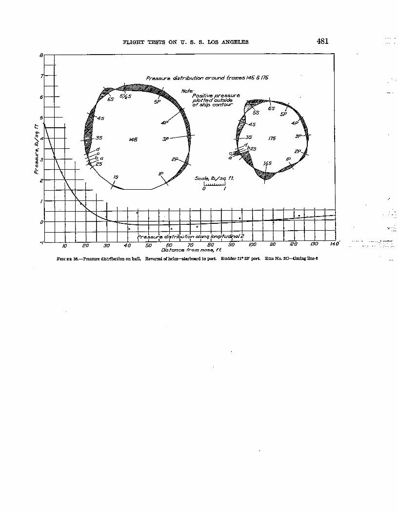
FLIGHT TESTS ON U. S.S. LOS ANGEIJZS 4s1 .
--
,,
.
... ...+_“. ..”.“.
I’IGUEE 86.-Presnre dlstrfbuihn on hull- =vasd of hehn—star board to ~. Budder 11”88’ w’L Firm NO. 8G-thI& k? 6