Embed Size (px)
Citation preview

y/REPORT DOCUMENTATION PAGE oMB No. o7o4- 168
1."a-C ec q zu eO no Z"=& Q( 't- C 4 .SRZ Zea I ?V %, .OW - c r4 U cX LX~ 11L A'wG &&-'qwr w-Ll ;.9 21 f4J rn
for rIOUorl's rre ' 10 Waxwqw~n oeacc~wn l a w, 0k% mX!a Wa ' w orrun, C0e0~cm an'd Aoni. 215 -'e0oso CJv A. . Skl &, Ia 4. AinV. .A A3C aj0Id -4I Mc~fE o A r P&qAUrV AtfIa -,-<a of VVAtt AMi Su*W8~do. 'NM~r'stW. DC 2C5CM
1. AGENCY USE ONLY (LawW 61atwj 2. REPORT DATE 3. REPKRT TYPE ANn OATES COVERED
August 14, 1990 Final4 " TfTLE AN SUBTITLE S. FUNDING N' DRT ICA User-Friendly Graphics Toolkit for Network Management
0 PR00f ELECTE
6. AUTHOR(S) AUG22 90N CPT James P. Hogle "
7. PERFCRMING CRGANIZATfCN NAME S) ANO A00RESS(ES) 8. PERFORMING ZPGANIZATICNd
U.S. Army Student Detachment, With duty at University of REPORT WkiLKA
Washington, Seattle Washington 98195.
. SP0ONSCjHG. MONIT QRING AGENCY NAMES)AN AOORESS(ES) .0. SPONSPNGCdITCR;NG AGE'.CY
U.S. Army PERSCOM (DAPC.OPB-D) REPORT NUMER
200 Stovall St -
Alexandria Va 22332
11. SUPPLE.MENTA.Y NOTES
Source Code for this toolkit is available on request from Professor Hellmut GoldeUniversity of Washington Department of Computer Science and EngineeringIt is also available by email from [email protected].
i2a. DIST RIEJUT. :C&AVA;LASILiTY STATEMENT .2b. DISTRIBUTION COLE
Unclassified, Unlimited Distribution.
13. ABSTRACT /.U.rru 2C0 "v-d$)
> This thesis describes the Network Graphics Toolkit, which was developed tosimplifythe creation of graphical network management applications. It was developedlusing the X11R4 release of the Athena Widget Set and the X Toolkit Intrinsics. Italso includes calls to X Library functions when necessary. It was designed to workwith a broad range of network management applications and implemented with thegraphics code kept distinct from the application's code to improve portability. Thetoolkit's features and limitations are described in detail. The thesis alsoevaluates a number of graphical programs, assessing the appropriate capabilitiesfor a graphics toolkit. Finally it discusses the suitability of the Athena Widgetsfor large graphigal applications, and related applications that have implementedthe toolkit. SHo 5AI4M
} / __ _ _ __-_ _ _
IAp~ocad ko pubc mbum
14. SUBjECT TERMS -- I IS. NUMBER OF PAGES
X Windows, Workstations, NetWork Management, Athena Widget Set g216. PRICE COOE
7. SECUP fY CLASSIFICATION te. SECURITY CLASSIFICATION ;. C URITY CLASSIFICATION 20. UMITATION OF ABSTRACTOF ' ,O, UI~ C 'ISS AG I OF ABSTRACT
'EMSIFIED TULAMfIED UNCLASSIFIED UNLIMITED
N 1S4S-01-2a0-5a W ' a Fo -m 36. a 8922 Or
sa75OOi2O5SO ,I6 by ANSI 1hd. 23IS 1

p
A User-Friendly Graphics Toolkit For Network Management
by
James Phillip Hogle
A thesis submitted in partial fulfillmentof the requirements for the degree of
Master of Science
University of Washington
1990
Approved by - / ~ 'j(cHellmutGolde
(Chairperson of the Supervisory Committee)
Program Authorizedto Offer Degree- t /_ 4 -f~ L- V
Date A_-,/ £ ,i i /f'?"
90 O8 8 0 13a

Master's Thesis
In presenting this thesis in partial fulfillment of the requirements for a Master's degreeat the University of Washington, I agre-- that the Library shall make its copies freelyavailable for inspection. I further agree that copying of this thesis is allowable only forscholarly purposes, consistent with "fair use" as prescribed in the U.S. Copyright Law.Any other reprcduction for any purposes or by any means shall not be allowed withoutmy written pernuission.
Signature
Date 4 t-/g
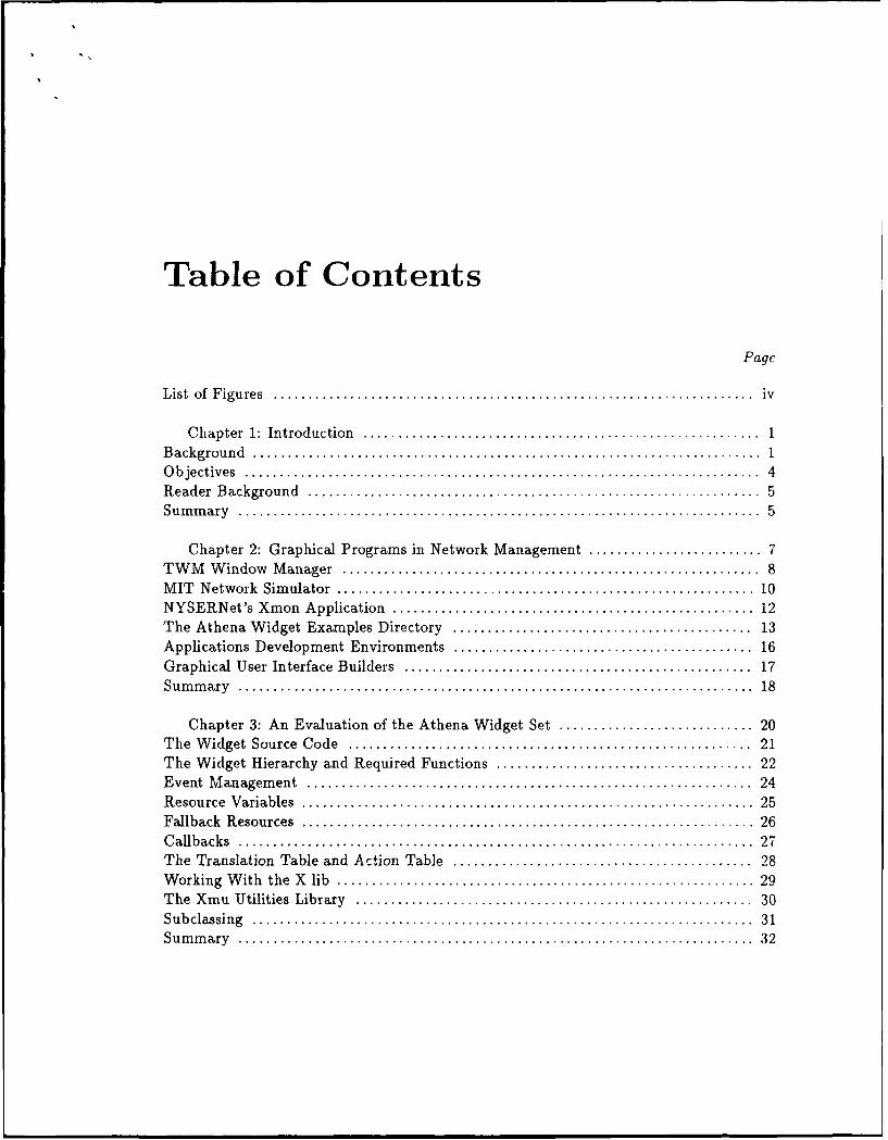
Table of Contents
Page
L ist of F igu res ..................................................................... iv
C hapter 1: Introduction ......................................................... 1B ackgroun d ......................................................................... 1O b jectives .......................................................................... 4R eader B ackground ................................................................. 5Su m m ary ........................................................................... 5
Chapter 2: Graphical Programs in Network Management ......................... 7TW M W indow M anager ............................................................ 8M IT N etwork Sim ulator ............................................................ 10NYSERNet's Xmon Application .................................................... 12The Athena W idget Examples Directory ........................................... 13
Applications Development Environments ........................................... 16
Graphical User Interface Builders .................................................. 17Sum m ary .......................................................................... 18
Chapter 3: An Evaluation of the Athena Widget Set ............................ 20T he W idget Source Code .......................................................... 21The Widget Hierarchy and Required Functions ..................................... 22
E vent M anagem ent ................................................................ 24R esource V ariables ................................................................. 25Fallback R esources ................................................................. 26C allbacks .......................................................................... 27The Translation Table and Action Table ........................................... 28
W orking W ith the X lib ............................................................ 29T he X m u U tilities Library ......................................................... 30S u b classin g ........................................................................ 3 1S u m m ary .......................................................................... 32

Chapter 4: Discussion of the Project ............................................ 34T he G raph Editor .................................................... ........ ... 38T he M enu Interface ................................................................ 43
T he T ext Interface ................................................................. 46T he F ile Interface .................................................................. 46
The Data Structure and Naming Conventions ...................................... 48U sing the T oolkit .................................................................. 50
The Suitability of the W idgets ..................................................... 51
Su m m ary .......................................................................... 53
Chapter 5 Continuing Work and Related Applications ........................... 54
UW Dynam ic Network M anager .................................................... 54T racerou te ......................................................................... 55Separating the Graphics From the Application ..................................... 56
S u m m ary .......................................................................... 57
Chapter 6 Discussion of Future W ork ........................................... 58Using the Toolkit for Other Types of Applications .................................. 58Further Refinements With the Athena Widgets ..................................... 59C on clu sion ......................................................................... 6 1
B ibliography ................................................................... 63
Appendix A The Communications Interface ........................................ 67Appendix B MAN Pages For The Application ...................................... 71Appendix C Summary of the W idget Set ........................................... 82
Appendix D Examples of The Toolkit's Graphics ................................... 86
Aoession For
N T i S CG-RA&I'DTIC TAB 0Uuaanounced 13Just ificatio
By
Distribution!
Availability Codes
1 vaii and/or
Dist Speolal

List Of Figures
Figure 1 Applications Development Toolkits ....................................... 2
Figure 2 NYSERNet Xmon Graphics ............................................... 13
Figure 3 Widget Hierarchy for the Graphics Toolkit ................................ 36
Figure 4 Initial Graphics Produced by a Call to the Toolkit ......................... 37
iv

Chapter 1Introduction
In 1984, Apple Computer released the Macintosh personal computer. This small com-
puter pioneered a new type of interface for the computer user. With the Macintosh, the
use of a mouse as an input device was popularized, with menus and icons allowing the user
to move from application to application. This concept of the smooth, easy to understand
interface has since been a design goal of many major applications. A graphical interface
is ideal for Network Management applications because computer networks are hard to
visualize if the manager is given only a list of nodes and their connections. A graphical
display of network connectivity is almost mandatory. Today, Network Management ap-
plications are hard to write because the programmer must use the X Library [1] or some
other graphical Applications Development Environment (ADE) to display the program's
output and take input from the user.
This thesis introduces a method for programmers in the Network Management field
to write high-quality applications without having to learn an ADE. I have developed a
toolkit that uses the Athena Widgets [2] to provide a graphical interface including a simple
communications protocol.
1.1 Background
In the early 1980's, the Massachusetts Institute of Technology (MIT) began to develop

2
a set of protocols called X Windows, or simply X [3]. These protocols were implemented
with the X Library functions . X gave programmers a means of controlling a bitmap screen
to do graphics on workstations. It has since become a standard for many workstations.
Three ADEs are compatible with X, OpenLook,[4] Motif, [5] and the Athena Widget Set.
OpenLook uses functions from the X Library or X lib as the base for its functions. The
Athena Widgets and Motif are based on routines from the X Toolkit Intrinsics[6] as well
as the X Library. The relationships for these three ADEs are shown below.
A otif I
Widgets JOpeniLookX Toolkit Intrinsics
X lib
Figure 1: Applications Development Toolkits
Writing graphical applications by using direct calls to the X Library typically requires
much more work than the use of ADEs. It consists of a large number of routines that
manipulate several complicated data structures. Applications with many calls to the X
Library require many global structures and variables to pass data around. This makes
the application's design more complicated and the maintenance of the code much harder.
I studied a number of X Library based graphical applications, including Tom's Window
Manager,[6] NYSERNet's Xmon,[7] and the MIT Network Simulator,[8] that all use global
data structures for the graphical portions of their programs. Most of these programs were
developed before ADEs became widely available.

3
Writing applications with the X Library requires the programmer to do a lot of work
just to get to the level from which these ADEs start. Designing the program's graphical
interface frequently puts the applications programmer at a disadvantage since graphical
design issues become very important to the ultimate success of a program. I saw, in my own
graphical interface development efforts, that users with little interest in the complexities
of the code had definite opinions about how to improve the interface (usually resulting
in a lot more work for me). Another advantage of using an ADE is that these toolkits
provide several advanced objects like Command Buttons with very good graphics.
A group at the University of Washington interested in Network Management issues
was looking for a toolkit to integrate a number of available Network Management tools
prior to developing an integrated network management system. I wanted to explore the
validity of developing a toolkit that a number of different programs could use to display
network management applications. I was limited by the lack of available commercial
Graphical User Interface (GUI) development toolkits and commercial ADEs. Available
were the Athena Widget Set and the Xt Intrinsics Toolkit which the MIT X Consortium
prur,ioted a higher level ioolkit fur X applications. The documentation describes a
Widget as, the primary tool for building a user interface or an application environment.
It is an X Window, implemented with information hiding, that uses semantics specific to
all widgets.[2]
It was a real challenge to figure out how to use the Widgets due to their scant docu-
mentation and general lack of examples. Ultimately, using the Widget Set, I developed a
very good toolkit for network management applications. In addition, the graphical inter-
face could be kept completely distinct from the code that gathers the network management
information. Keeping the graphics code separate from the application that uses it helps
make it easier to extend the code to other programs and other types of applications. Fur-
ther, the graphics code is designed to be very compatible with other types of operating
systems to aid in portability. I tried to avoid UNIX specific calls and used C language

4
input-output functions whenever possible.
This Network Graphics Toolkit can shield the application programmer from having to
learn the details of the Widgets, Intrinsics ar the X 1ib that it is bascd on, unless the
user wishes to extend the toolkit. To extend the toolkit, the graphics functions provide
a sorely needed example of how to write routines that use Xt Intrinsics primitives like
resources, translation tables and action tables. In fact, the code has examples of nearly
every major feature of the Athena Widget Set and the Xt Intrinsics Toolkits. Much of the
design of the toolkit was done concurrently with Walt Reibsig's UW Dynamic Network
Management Program [9]. The menu interface labels and file interface design was largely
influenced by his application. His SNMP based Network Management application uses the
toolkit as the graphical interface. The toolkit has also been used by another student, Scott
Murphy, to provide a graphical interface for his ICMP based Traccroute[10] application.
1.2 Objectives
My thesis has three main objectives.
" It introduces the Network Graphics Toolkit that was designed to simplify the devel-
opment of graphical Network Management applications. I will discuss the features
and limitations of this toolkit in some detail to give prospective users a feei for what
it can do for them and to suggest ways for further refinements. One sub-goal I had
for the toolkit was that it should work with a broad range of applications. A second
sub-goal was to keep the graphics code distinct from the applications code.
* It evaluates a number of graphical programs, to determine the appropriate capabil-
ities for a graphical toolkit.
" The Athena Widget Set and the Xt Intrinsics Toolkit will be discussed in some detail.
I will analyze the Athena Widget Set and the X Toolkit Intrinsics Libraries usefulneqs

5
as an Applications Development Environment. Further refinements of, or extensions
to, my toolkit require an understanding of these two libraries. This information is
provided to help reduce the challenges that a future Widget Set programmer will
face as he or she begins to develop graphical applications. This discussion will be a
gentle introduction to the X documentation and a review of other resources available.
If nothing else, the commented source code should provide a good example of what
the Widgets and the Intrinsics can do and how they do it.
1.3 Reader Background
The reader should be familiar with the C programming language to fully understand
the examples discussed. Additionally, a basic knowledge of workstation environments
and the X window system in general would aid in understanding the concepts under
discussion. A familiarity with the Unix Programmers Manual[21] sections on X and twin
are an important source of background knowledge for chapters 2 through 4. To learn
the range of possible applications that fall under Network Management the NOC Tools
Catalog[22] is an important listing of available applications in network management.
1.4 Summary
The remainder of this thesis focuses on the objectives presented in this chapter.
Chapter 2 outlines the challenge of Network Management and examines several graph-
ics programs and their capabilities that can be used as part of a graphical network man-
agement interface. It includes an analysis of several graphics programs written both with
and without the benefits of an ADE.
Chapter 3 provides a tutorial to help future users of the X-Athena Widget Set deal with

6
its peculiarities. I detail key concepts in the widget set, advantages of the widget set over
simply using X Library routines and then discuss the Utilities Library,[10] introduced wit li
X11R4, the latest release of X, to supplement the widgets. I cite examples of important
concepts behind the Intrinsics and Widgets and briefly discuss subclassing widgets to
change their behavior.
Chapter 4 provides details of the Network Graphics Toolkit, breaking it down into
functional components. It will include a discussion of how to use it, and how it was
implemented. Some of the more unusual aspects of its implementation will also be covered.
It will also assess the suitability of the Athena Widget Set and the X Toolkit Intrinsics as
an ADE.
Chapter 5 discusses recent efforts by other application writers to use my interface for
their non-graphical network management applications. It also puts my project into larger
perspective as a general purpose graph editor, and as an example of a large X-Athena
Widget application.
Finally, chapter 6 provides ideas for future work using the toolkit as a base. Possible
applications exist outside of the Network Management area, including a generalized graph
editor for applications that require one or as the front end graphics for an event driven
simulator. A few enhancements to the toolkit will also be discussed.

Chapter 2Graphical Programs in Network Management
Network Management is an area that is well-suited for graphical applications. A net-
work, once it is installed in an organization, quickly becomes essential to the organization.
Networks typically provide services like mail, file sharing, and improved access to avail-
able information and to CPU resources. The down-side of this dependence on networks
becomes visible only when the network goes down or when information is lost or delayed.
Even if the network only breaks occasionally, network failure can be devastating for the
organization and for the network administrator. Avoiding this trauma makes Network
Management a serious issue for most organizations.
Networks are inherently hard to monitor because they have so many possible points
of failure. Failure can take place at any router or any host and can occur in one of several
software protocols or hardware components. Failure can also occur because of a broken
connection between nodes. The load on a network is typically non-uniform, with occasional
periods of heavy loads. Additionally, certain types of networks have probabilistic features
like Ethernet's binary exponential back-off scheme, and their behaviors are not completely
predictable. Networks are dependent on very specialized hardware and very complicated
software protocols to run effectively. If buffers overflow because some node falls behind
or the line quality deteriorates, nodes that are not responsible for the problem may be
the ones detecting it. The network is also dependent on the reliability of the routers and
gateways that play critical roles in the forwarding of data to distant machines.

8
Most organizations have turned to Network Management solutions that keep the man-
agement overhead low by using well-designed reporting programs that inform human net-
work managers when management problems develop. The idea is to keep the management
staff as small as necessary to do the job. Graphical programs help these small staffs stay
on top of network management problems since they can more easily display the events
of interest with graphics. Non-graphical programs can identify network failures very well
today, but if these failures are not reported to the administrators in a clear manner the
problem may be missed. Additionally, large networks and their connections are extremely
hard to visualize without a map of some sort.
The University of Washington campus network has about twenty routers arranged into
a tree topology with many secondary links. These links further enhance the availability
of network services to all points on the network, despite the occasional loss of one or more
subnets or routers. Understanding how this network is configured from a table of routers,
hosts and links is difficult. I frequently saw network management application writers
spending hours drawing graphs from lists of routers and links trying to understand the
text output of their applications.
Most network applications using graphics completely embed the graphics into the
programs. I consider this approach to be bad, both for maintenance and flexibility of
the program. Embedding the graphics into the application dates the program and limits
its utility since better graphical ADEs continue to be developed. The remainder of this
chapter focuses or several graphical programs, some of which are network management
related, and describes how their graphics are implemented.
2.1 TWM Window Manager
One of the most important graphics programs on a workstation is the window man-
ager, and one common public domain window manager is Tom's Window Manager.t2l]

9
It is also called Tab Window Manager in the X11R4 release, or just twin. It provides
titlebars, shaped windows, multiple methods of icon management, user-defined macro
functions, click-to-type and pointer-driven input, and user specified key and mouse but-
ton bindings. The default settings can be modified using the .twmrc script file in the user's
home directory. The program is usually started when the user logs onto the system. It
defines eighty-three variables and fifty-seven functions for the user. The window manager
executable is over 226,000 bytes long and uses several megabytes of window manager spe-
cific library functions. The source code for the main program and the library functions
are over 391,000 bytes long. The program graphics were written strictly with calls to the
X Library. No calls to the X Intrinsics Toolkit or any other graphical toolkit were made.
The program is hard to understand since it is divided into twenty-six sparsely commented
C files using many X Library function calls.
The twm program provides an example of how the X Library can accomplish two
functions important to my toolkit. I first examined the source code to learn how the
program accomplished window movement. The section of the code responsible for the
movement of the windows on the screen is about 90 lines long, contained in a two-thousand
line file called events.c. It allows movement when the user clicks the left mouse button
on either the bar on top of the window or on any border of the window. It uses the X
lib function XGrabPointer to control input from the pointer while the window movement
takes place. The function XQueryPointer returns the window containing the pointer and
the coordinates of the pointer relative to the origin of that window. These functions
control the process and provide the location to the window manager data structure. This
enables the XMovelWindow function to set the window in the new location. Part of the
window movement function is a shadowing function that shows an outline of the moving
window while it is being dragged around on the screen. This feature lets the user know
exactly where the new window will be put down when he or she lifts his finger off the
button.

10
Another function of the window manager important to my toolkit was the notion of
iconifying and displaying the contents of a window. This capability is at the heart of the
window manager and was implemented with a data structure and several twm defined
functions that create and destroy windows and keep links to the files that contain the
information about the windows. This collection of functions is much more complicated
than moving the windows.
Trying to comprehend the details of the X Library as it was used in this program
prompted me to use a higher level toolkit to build my graphics. Though used frequently,
twm is one program that few users ever take the time to understand completely.
I used window movement and the concept of a popup window in my toolkit. I found
no easy way to implement window movement within the Athena Widget Set. To get
movement I used the same X lib functions as the window manager. Since twin handled
window movement as a part of a much larger window handler function I could not directly
use the function from the window manager. I did use an Athena Widget Set concept that
let me tie mouse clicks to the X lib based functions I wrote.
I implemented popup windows in my toolkit using the Athena Popup Widget. It
calls another type of widget that displays information or prompts the user for certain
data. This concept was easier to use than the iconification and display functions that
maintained information in the window manager.
2.2 The MIT Network Simulator
The MIT Network Simulator[6] is an event driven simulator that simulates and displays
nodes and links including ethernet, token ring, and point-to-point networks. It was
written in 1988 using the X Library. As a result, the source code is very long, over 550
kilobytes, and is fairly difficult to follow. Some effort was made to separate the graphics
functions from the simulation code; however the graphics code is still dispersed in about 8

11
of 30 files in the application. It is tightly bound to the simulation code; there is no way to
reimplement the simulator using an ADE without completely rewriting most of the code.
This simulator generally provides reasonable results, uses colorful graphics and is flexible
enough to simulate networks up to about 60 nodes. This limit is based more on the lack
of screen space than other limitations.
There are several graphical features of this program that are interesting to consider
when designing a network management toolkit. The mouse is used to move nodes, dnd it
is used to draw and delete lines between nodes with ease. The program includes a point
and click menu driven interface. The main menu appears in the upper right corner of the
display as a square box, leaving plenty of space for the application to display the nodes
and links being simulated. The simulator also has an area at the bottom of the display
where the user can provide text input.
The program's interface for adding links between nodes is very weak. It requires that
the user add the link between the nodes (which shows up on the screen as a line), then
add each path to the network of nodes by clicking on the nodes in the path one at a time.
Then he or she must add the return links from the destination back to the origin. There
was no sure way for the user to tell if the path was actually added to the database without
writing out the state of the application to a text file, suspending the simulator process to
look at the file. Many users simply edit the text file to add links to avoid using this run
time interface.
My toolkit borrowed several concepts from the MIT Network Simulator. I chose to
use many of the same functions for line drawing, since the Athena Widgets have no means
to draw a line. This meant that my toolkit had to define a graphics context that was a
solid black line and call the X lib routine XDrawLine, just like the simulator (see Chapter
3.8 for further details). Other functions such as the point and click menu driven interface

12
were implemented with higher level X-toolkit constructs.
2.3 NYSERNet's Xmon Application
Xmon[7] is the primary network status monitoring application in the NYSERNet
SNMP application release. It is a graphical network status monitoring and querying
program that uses the Simple Network Management Protocol[23] to get the status of var-
ious nodes specified in a configuration file. The program periodically queries the nodes
over the network and, depending on their replies, sets the background color of the nodes
to be red(down), orange(uncertain) or green(operational). It was implemented using only
X lib functions for its graphics. The University of Washington Campus Network displayed
with version 4.0 of Xmon (released in July 1989) is shown in Figure 2, albeit in black and
white.
Several aspects of the Xmon application are of interest. It uses color graphics to
indicate the node status and the network type. Network types are displayed with different
shaped lines. It uses one-line labels to name both the nodes and the connections. It also
uses a configuration file to fix the location of the nodes on the screen. The application
is bounded by the limited size of the display screen. This program is a primary tool for
network managers at the University of Washington and is widely used at other university
and corporate sites as well.
Xmon's graphics closely resemble those of my toolkit. The features that NYSERNet
implemented using X lib were implemented with the Athena Widget Set and the X Toolkit
Intrinsics in my toolkit, except for the features mentioned in the previous sections, namely
movement and line drawing. Differences in the appearance between the NYSERNet ap-
plications and my toolkit were due to the deliberate design decisions. It would not be
difficult to convert my toolkit to provide graphics identical to Xmon.

13
QoUITiBell On Status OnlLogging On intervall 0 1 1
SNMP Network Monitor Version 4.0 126 192 129 192
LeedCopyright NYSERNet Inc. 11111USNDr rc
--- Dow-Up
.. onKib o r208: 176:atmos 11Is: 100:npl*Unknown E1:iiy 4A
-ANUk 2f ly 26E
QRing 12195.1211 1211.05.1112 40:adm 216:dvictr 76:phys 243:DPH
128 18212 10 18 12 128 182
Elecrolu Dusbustr ReinaSliverking
22:1211206:1w 112:ndc 1U:PPU 79:j :%33:gug
238:e gr 16:geo 19:C net 120:nde Be: 250:0TH 143:E i4o:FTR
19:COEnat 22:amath 1: S 1s: cc 214:ChemE 226:Psrych 222:SCC 2o6:CDC
129 192
A&das 3:E246: u IS0:bIoE 60:s 36:forest
252: 0a 244taIcOM 172:c am
72:CSSCA 82:FMO 200:hacc 144:CQS 104:I1b, 16:MUslc
129 192
Ma~y 141: on 140 McCarty 90:g cc
1942: sgea 143:McKenzie 216:3 c 2:engi
90:ant 102:ougi .97...E 1-4:FIS 57:BRY 168:arch 184:HFS112:3 0om 4M
156:8j
@-EE 236:purch
Tue Jul 24 13.47:52 lawC:: interface 2 at DirtDevi came UP
Figure 2: Xmon 4.0 Display of the University of Washington Campus Network
2.4 The Athena Widget Examiples Directory
The X11R4 Release from the MIT X Consortium includes a directory of example

14
programs implemented with the Widgets and Intrinsics libraries. These programs range
from the simple Hello World program to one called xwidgets that uses nearly every widget
in the R4 release. Again, widgets are typically associated with X Windows, have specific
capabilities as part of a user interface or application environment, and are implemented to
use information hiding. Several of these programs have very interesting features relating
to Network Management.
The most basic example is the file xhw.c, which draws a box on the screen with the
words, " Hello World" inside. It uses only four lines of source code. The example outlines
the properties of any Athena Widget based application. An article by David Rosenthal
[11] describes a program with identical output as requiring 40 lines with X lib calls. I used
Hello World as a template to develop main.c in my toolkit.
One of the examples, popup.c, allows the user to specify a color to change the command
button. Specifically, the application creates a window that says, "Press to see Simple
Popup Demonstration". When the user clicks that window a new window pops up and
asks the user, "What color should the main button be?". This new window also provides
space for the user to type in the color and "OK" and "Cancel" buttons. After the user
types in the color the second window disappears and the main button changes to that
color.
Two aspects of popup.c were important to my toolkit. First, this is the only example
with a dynamic color change. The ability to change the color of a window dynamically
is very important in a graphical Network Management application. Colors can display
the operational status of a node clearly. Second, this function allowed the user to hit the
return key after typing in the color instead of clicking the mouse button on the "OK"
window. This feature is very convenient when implementing a point and click interface
that requires the user to input text at the keyboard.
Though simpler than X lib, the widgets can still be difficult to use for simple tasks.
The popup.c example uses 39 statements from eight of the thirteen chapters and from

15
two of the five appendices in the X Toolkit Intrinsics[6] documentation. Furthermore, the
relationship between the functions are very poorly covered in the documentation. What
should be a simple task, changing the background color of a widget, is very difficult. I
used the same approach as the program to include both the color change and the return
key press in my toolkit. Without access to this example dynamically changing the colors
of the widgets would have been much harder to implement.
Another extremely valuable example was the file xmenu2.c. This file opens up a
window that says, "Click here for menu". When the user clicks the mouse button in that
window a window pops up that has a label and several possible items to select. When the
user selects one of these items the user's xterm window that started the program states
that the appropriate menu number was selected. The menu items all have different font
sizes.
The xmenu2.c program's multiple font settings and the popup menu window are sig-
nificant to a network management application. Variable font sizes allow some text to be
reduced, providing more room for the application to use. Also, the popup menu window
allows the application to nest menu windows under main menu buttons so that more menu
selections can be made without cluttering up the screen with related or infrequently used
menu buttons.
I directly used both notions in my toolkit. A small boldface font size for the nodes
makes it much easier to fit nodes on the screen. The toolkit also uses popup menu windows
since there are several related functions, such as printing information on the screen or
dumping it to a graph, that need not be given separate main level menu buttons.
This example was the only rtference available to me that covered how to specify fonts
using the X toolkit. Virtually no mention of fonts is made in the Athena Widgets or
the Intrinsics documentation. The X-Library describes some functions for low-level font
specification, but does not explain what is covered in the program. Without this example
I could not have reset the fonts the way I did. Again, the examples provided important

16
assistance that the manual did not offer.
A third example that was especially valuable was the program xwidgets.c. It offered
examples of 23 widgets in the Athena Widget Set. The program creates this collection
of widgets to show how they can be composed and provides an example of each. This
was interesting from a Network Management standpoint since it hinted at the flexibility
of the widget set and provided important examples for adding windows. The example
implemented horizontal and vertical scrollbars to allow movement around the display
space of another window. It also implemented a text window that periodically took input
from a file. Finally it implemented a histogram window called the StripChart Widget.
My toolkit used some of these concepts. Scrollbars allow it to manage displays larger
than the actual screen space. It is helpful to eliminate the limitation that the screen can
have on the size of the network that can be managed. Another concept used was the
ability to periodically read and display text information directly from a file. This allows
the application to send long messages through the toolkit to the manager, if necessary.
One concept in this example program that I did not implement was the histogram. This
could be particularly valuable for displaying certain paramet,rs for a node or set of nodes
in future updates to my toolkit.
The example programs introduce the capabilities of the Widget and Intrinsics as an
ADE. They give the application writer a feel for what is possible using this ADE. The
examples go well beyond the manual in explaining the relationship between various In-
trinsics and Widget functions. A more detailed discussion and evaluation of the Athena
Widgets will be given in Chapter 3.
2.5 Application Development Environments
A number of high-quality Application Development Toolkits have recently been devel-
oped. One Xt Intrinsics based Applications Development Environment is Motif,[8] which

17
generally provides much better graphics than other toolkits. The graphics have a three
dimensional appearance, with buttons that appear raised when " off" and depressed when
"on". This is a more sophisticated method of sending a visual signal to the user than
reversing the foreground and background color as in other toolkits. Motif is implemented
with its own widgets and has another object called the gadget. A gadget is a windowless
widget that keeps less state than conventional widgets, but provides some of the same
functions. It is designed to improve performance and require less server overhead than a
widget.
Motif's main competitor is OpenLook,[3] which is based on the X Library. OpenLook
was designed with visual design, simplicity, consistency, efficiency, device independence
and interoperability with existing systems in mind.[25] Like in Motif the user can dy-
namically change fonts. He or she can also change the background color of any window
dynamically. These changes are made by opening a property window that provides rou-
tines to change the state of the window. When the background color is reset by the user,
the foreground color of OpenLook applications may also change to insure a strong contrast
between the colors. The mouse cursor in an OpenLook application is commonly moved or
"warped" in X lib terminology, to the default button screen image. This minimizes the
amount of distance that the user will have to move the mouse.
David Simpson[14] notes that OpenLook and Motif are conceptually very similar and
believes that programmers can easily learn the other if they already know one. Neither of
these programs were available to me. It is possible to reimplement my Graphics Toolkit
with one of these Toolkits to get a slightly higher quality of graphics.
2.6 Graphical User Interface Builders
A number of user interface development programs are now becoming available such
as Sun Microsystem's Graphical User Interface Design Editor (Guide).[12] The user can

18
create a graphical interface with menu buttons and input boxes to prompt the user for
certain information. He or she must still write the callback routines required by each of
the menu buttons. These callback routines can get fairly complicated, but the overall
savings in development time would still be significant.
Guide and other programs in this class let the applications writer construct the inter-
face on the screen using the mouse and generate C language code. With a menu builder,
the applications programmer has the interface automatically built for his applications.
The development of my toolkit would have been simplified by a program such as Guide.
2.7 Summary
This chapter described the tuim program, the MIT Network Simulator and the NY-
SERNet application Xmon. All three of these programs were implemented using the X lib,
and provide important lessons about interface design. Twm provided an example of win-
dow movement, and windows that can be reduced to a small object, the icon. The MIT
Network Simulator provided an example for a menu interface and the display of nodes
and networks as a collection of boxes and lines. Xmon showed the utility required by
applications that monitor networks, including multiple color codes and irregularly shaped
network objects.
The Athena Widget example programs show what simple toolkit applications can
do. The functionality of many of the examples are useful to a graphics toolkit. The other
ADEs such as Motif and OpenLook, provide functionality not available in the X lib and the
Athena Widgets. Other products are now being developed that promise more streamlined
applications development.
An large amount of work is currently taking place to design and improve graphical
program interfaces. Much needs to be done before we reach a point where we can be
satisfied with these interfaces. The same is true for the quality of available Network

19
Management programs. These programs are usually written with embedded graphics
which makes them harder to maintain and extremely hard to convert as newer and better
graphics toolkits are developed.
Chapter 3An Evaluation of the Athena Widget Set
In light of the difficulties of writing applications using X lib, the value of ADEs like the
Athena Widget Set/ X Toolkit Intrinsics is apparent. The concepts behind the Widget
Set and the Intrinsics are not difficult. They are worth reviewing even if the reader has
no intention of working with the Athena Widgets. Many of the abstractions behind the
Widget Set and the Intrinsics are common to other ADEs. Since Motif is implemented
using these same X Toolkit Intrinsics, these concepts are common to that environment as
well.
The documentation of the Athena Widget Set and the X Toolkit Intrinsics offers an
enormous amount of explanation but very few complete examples. The problem gets worse
trying to understand the meaning of all the terms used without explanation. The Widget
abstraction is meant to spare the graphics programmer from having to worry about all
the details of the X-Library. In that regard the widgets are partly successful; however it
is still extremely hard to master the Athena Widgets.
The concepts to examine are the Widget Hierarchy, Event Management, Resource
Variables, the Fallback Resources, Callbacks, and Translation Tables and Action I'ahle..
They are best examined in the context of the manual's explanation, iheir syntax, and
some examples of what these features provide for the programmer. It is also worthwhile
to explain what the Widget Set does not do and to briefly cover some of the things that
are abstracted away by the Widget set. I will conclude with a discussion of the various

21
libraries examining what they can do for the programmer and then look at subclassing
widgets.
3.1 The Widget Source Code
The Athena Widget Set documentation[2] should be consulted first by the widget
programmer. Another source of information is the source code for the widgets. Appendix
C briefly describes the function of each. The source code in the release is written in
C, and is well commented and easy to follow. It provided almost as much help as the
documentation when trying to figure out the behavior of the widgets.
The code for a widget consists of a public header file (for example, for the List Widget,
List.h), a private header file (ListP.h), and a widget source file (List.c). The key functions
in determining the behavior of the widgets rests in two files, the private header file and
the widget source file. The private header file sets up the inheritance hierarchy of the
widget. Knowing the superclass of the current widget can be significant in determining
it's behavior. The source file has a section that lists the inheritance functions and the
widget specific functions. An example from the source file for the List Widget follows:
#define superclass (&simpleClassRec)
ListClassRec listClassRec {{/* core-class fields initialization *//* superclass */ (WidgetClass)superclass,/* class.name */ "List",/* widget-size */ sizeof(ListRec),
/* realize */ XtInheritRealize,
/* Simple class fields initialization */
{ / * change~sensitive * / XtlnheritChangeSensitive
}
22
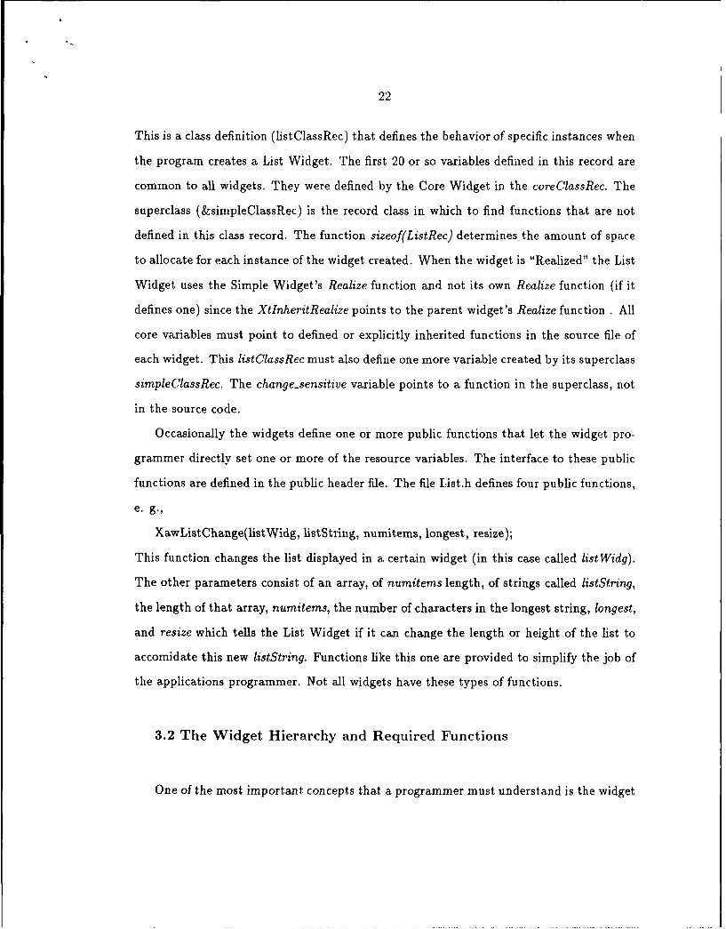
This is a class definition (listClassRec) that defines the behavior of specific instances when
the program creates a List Widget. The first 20 or so variables defined in this record are
common to all widgets. They were defined by the Core Widget in the coreClassRec. The
superclass (&simpleClassRec) is the record class in which to find functions that are not
defined in this class record. The function sizeof(ListRec) determines the amount of space
to allocate for each instance of the widget created. When the widget is "Realized" the List
Widget uses the Simple Widget's Realize function and not its own Realize function (if it
defines one) since the XtInheritRealize points to the parent widget's Realize function . All
core variables must point to defined or explicitly inherited functions in the source file of
each widget. This listClassRec must also define one more variable created by its superclass
simpleClassRec. The change-sensitive variable points to a function in the superclass, not
in the source code.
Occasionally the widgets define one or more public functions that let the widget pro-
grammer directly set one or more of the resource variables. The interface to these public
functions are defined in the public header file. The file List.h defines four public functions,
e. g.,
XawListChange(listWidg, listString, numitems, longest, resize);
This function changes the list displayed in a certain widget (in this case called listWidg).
The other parameters consist of an array, of numitems length, of strings called listString,
the length of that array, numitems, the number of characters in the longest string, longest,
and resize which tells the List Widget if it can change the length or height of the list to
accomidate this new listString. Functions like this one are provided to simplify the job of
the applications programmer. Not all widgets have these types of functions.
3.2 The Widget Hierarchy and Required Functions
One of the most important concepts that a programmer must understand is the widget

23
hierarchy. The widgets in an application are defined in a tree structure. The root of the
tree is the shell widget that is generally called toplevel. This widget is not manifested as
a window; its only purpose is to be the root of the widget tree. The Widget Set next has
several types of composite widgets that can have several widget children. These composite
widgets include the Form, Box, and Dialog and Paned widgets. The Network Graphics
Toolkit uses the first three of these composite widgets. One instance of the Form, Box or
Paned Widget typically is used as the application window. These widgets can have other
composite or simple widgets as children. Simple widgets include the Command, Label,
List, Toggle, and StripChart Widgets. Simple widgets typically do not have children.
There are also a few widgets that can have exactly one child, like the Scrollbar and
the Viewport Widgets. Appendix C briefly lists the different widgets and some of their
capabilities. X-Widget applications generally appear to be very similar since they use
many of the same widgets and attempt to reset only a few defaults. For the specific
widget hierarchy used in my toolkit see Figure 3, in Chapter 4.
There are a few functions that the Widget Programmer must understand. These
functions do some very basic things like creating and destroying widgets. Four basic
toolkit functions are used in the next example. Except for several "include statements"
and comments a copy of the file xhw.c discussed in chapter 2 follows:
String fallback-resources[] = f "*Label.Label: Hello, World", NULL };
main(argc, argv)int argc;char **argv;{XtAppContext app.con;Widget toplevel = XtAppInitialize(&app -con, "Xhw", NULL, 0,
&argc, argv, fallback-resources, NULL, 0);(void) XtCreateManagedWidget("label", labelWidgetClass, toplevel,
NULL, 0);Xt RealizeWidget toplevel);XtAppMainLoop(app-con);
The XtApplnitialize function must be the first toolkit function called. It sets up a state

24
variable called the application context (app-con) and returns the shell widget (toplevel).
These variables are called by several functions throughout the life of the application.
The XtCreateManaged Widget function creates one widget in the widget hierarchy. The
XtRealize function makes the widget and all its children visible. Typically it is called
once on the shell widget only to make all of the application visible. The XtDestroy Widget
function (not shown) makes the widget and all its children disappear and frees all the
structures associated with the widget and its children. The function XtAppMainLoop is
an Event Management function and will be addressed in the next section. Familiarity
with these routines makes it easier to understand any application.
3.3 Event Management
The Xt Intrinsics Toolkit eliminates much of the complexity behind event management,
which is key to any graphical user interface program. Graphical interface applications
typically have some startup code that builds the interface before the application drops
into the main loop. The higher level interfaces generally spare the user the complexity of
writing the main loop code. This is true for the Athena Widgets since they use the Xt
Intrinsics event management functions. The function that puts the application into the
main loop is XtAppMainLoop. Generally this is the only event management function that
is used in Athena Widget based applications and it is only called once.
Events are user actions like typing at the keyboard, clicking on a button with the
mouse, or receiving input from an application program. The widget event manager auto-
matically registers and processes these events. There is no need for the program writers to
get involved in writing code that puts these events in a loop and checks them periodically.
For extremely complicated applications such as my toolkit, XtAppMainLoopis not suffi-
cient. The XtAppAdd TimeOut (app-eon, TIME-INTERVAL, namedFunction, client-data)
function is an event management function that calls the function named as a parameter

25
(namedFunction) after a designated period (TIME-INTERVAL), passing any parameters
specified in the argument list (client-data). Once this period elapses the procedure is
called and the event manager removes the time out. Just the time out and a pointer to
the routine to call go into the event manager structure. This function provides a parallel
type of event manager for the user.
An event management function that synchronously changes the event management
queue is XtAppAddlnput(app-con, inputSrc, condition, proc, client-data ). This function
registers a new input source (inputSrc) with the event manager that calls the callback rou-
tine (proc) whenever the input source condition (condition) is satisfied. For my application,
this function would be a better long-term approach for process to process communica-
tion than the asynchronous approach used by XtAppAddTimeOut. It is unclear from the
documentation whether this function would permit the applications to communicate with
named variables, sockets or ports or only through the Unix file system. This approach
certainly deserves more exploration. There are a number of other procedures that can be
used for event management but as long as the widgets permit the programmer to avoid
getting involved with the details of event management, they are not significant.
3.4 Resource Variables
One concept critical to manipulating the widget is the notion of resource variables,
normally just called resources. Each widget usually has a few dozen of these variables
that are defined when the widget is created. When a widget is created its resources are
either specified by the user or the default parameters are used. The best way to specify
parameters is by using public functions defined in the widget's public header file. Since
most widgets do not have public functions, a more typical way to specify resourcess is
to build an argument list with one or more calls to the XtSetArg function. With this
function values of the correct type are assigned to the corresponding resource names.

26
Next the application must call the XtSetValues function with both the argument list and
the widget name as parameters. There are many examples of this in my code; further
discussion of this method of parameter specification is beyond the scope of this thesis.
3.5 Fallback Resources
One other important way to set resource default values is through the fallback re-
sources. These must be specified in the main Athena Widget application file for all the
widgets in the application. Some resource values like the fonts can only be specified with
this method. Here is a small part of the fallback resources for my application.
String fallback.resources[] = {C*List.default Columns: 1","*List.forceColumns: True"," *extraDialog*label.resizable: True","*extraDialog.value:",
}
The meaning of the text is very simple. If the first letter of the name following the ""
is capitalized, then the string that follows will apply to all the widgets of that type. If
the name following it is not capitalized, then the name refers to the one widget with that
name in the application. The information after the colon is the value to be assigned to
the resource. This is an easy way to set a large number of default values at once. The first
two lines in the above example sets two defaults that make all List widgets one column
wide and force the widgets to comply with the new default column widths. The third
and fourth lines apply to the Dialog widget that is used when the application wishes to
directly query the user for string input other than what it gets from the menu interface.
This allows that widget to take variable length input (resizable: True) and sets the initial
value visible in the text area to blank space( "...value:").
One last thing to note is that not all the resources are settable by the programmer.
The manual details the names and the types of the resources for each widget and whether

27
or not they can be set.
The different methods of setting resource values use the following priority system: Ex-
plicitly set values using the function XtSetArg or a public function such as XawListChange
have a higher priority than defaults set by the falback resource list. The fallback resources
have priority over the default setting of the widgets, with the lowercase fallback resource
item having priority over the uppercase fallback resource item.
3.6 Callbacks
Callback routines are the routines that are executed in response to some user action
like a button press or a button release. Callbacks are added to widgets through one of two
methods. The first is exemplified by XtAddCallback(close, XtNcallback, Close Text Window,
NULL); This call adds the function Close Text Window to the callbackList resource of the
widget close in the file, text.c. The last parameter can contain a pointer to any structure
that the application wishes to provide to the function Close Text Window. This form is
commonly used for Command and Toggle widgets.
The method shown below is used to both create a button in a dialog box and to tie a
callback function to a button press event of that button.
XawDialogAddB utton(extraIntDialog, "Ok", HandlePromptForIntInput,(XtPointer) extraIntDialog);
This example creates a button called Ok for the dialog widget extraIntDialog that when
pressed calls the function HandlePromptForIntInput. One important point worthy of
comment is the warning on page 99 of the X Toolkit Intrinsics documentation. Describing
the functionality of the callback interface it reads:

28
Except where otherwise noted, it is the intent that all Intrinsicsfunctions may be called at any time, including from within callbackprocedures, action routines and event handlers.
NoteThe words "it is the intent that" in the preceeding sentenceindicate that there are known bugs that remain to be addressed insome implementations.
1
The above warning may explain those times when the callbacks did not work as expected.
The syntax for handling callbacks is fairly complicated. There are several examples
of callbacks in the examples directory and in my file, popup.c. It is the callback interface
that enables command and toggle buttons to call the routines that do the real work.
3.7 The Translation Table and Actions Table
The translation table ties keyboard or mouse events to callback routines. This enables
other widgets to be used in the same way as the command widget. I used the translations
table in several different ways.
char hostsTranslations[]"BtnlDown: Start()BtnlMotion: MoveHosts()
Above is a part of the translation table to provide the movement capability for the nodes
in my graph editor. The function Start is called when mouse button 1 is pressed down
inside a host widget. When the user moves the mouse on the pad while holding the first
button down the function MoveHosts is called.
The translation table management routine requires the referenced routine, (Start or
MoveHosts), to be defined in the widget source code or that of its parent in the inheritance
hierarchy. In my application I did not put any code in the widget itself, which is what
a usor would do to subclass a widget. Instead I used an Action Table. If the translation
'Joel McCormack, X Toolkit Intrinsics - C Language Interface, X Window System,
X Version 11, Release 4, 1988, r. 99, pages 207.

29
manager cannot find the function name in the widget code it will then check the Action
Table.
The Action Table provides a mechanism for user defined routines to be called from
a translation table. This makes it possible for the mouse to be used to call user defined
functions by being clicked in a window. The action table must be part of the primary
file in the application and must be added to the application in the main function. There
is normally only one Action Table per application. I register all the functions in the
translation tables in the Action Table. It is the combination of the action table and the
translation tables that make it possible for the mouse to be used effectively.
3.8 Working With the X lib
The X Library confronts the user with hundreds of functions and tens of data struc-
tures. There are times when the Widget programmer has to deal with the X Library to
do things that the widget set will not do. For example, the widget set will not allow the
user to draw lines or to dynamically reset fonts. These can only be accomplished with the
X Library.
By looking at how the X Library allows the user to draw lines, the reasons for using
the higher level functions become more clear. The function that is used for line drawing
is XDrawline(display, drawable, graphicsContext, xl, yl, x2, y2). Getting the first three
parameter values requires additional code such as shown below in the function Initialize-
Lines. The only purpose of the function in build.c is to create a graphics context called
gcfore for a solid black line. The code for this function follows:

30
GC InitializeLines(){GC gcfore;Display *display;Window win;Pixel color;unsigned long black;display = XtDisplay(theForm);win = XtWindow(theForm);black = XBlackPixel(display, 0);gcfore XCreateGC(display, win, 0, NULL);XSetForeground(display, gcfore, black);XSetLineAttributes(display, gcfore, 0, LineSolid, CapButt, JoinMiter);return(gcfore);
This function first calls two Intrinsics functions and four X Library functions before the
graphics context for drawing lines is set. The Intrinsics functions merely get the low-level
Display and Window variables from the widget theForm so they can be used by the four
X lib functions. The XBlackPixel call returns the machine specific color for a black pixel.
The XSetForeground function takes the graphics context created by XCreateGC and sets it
up according to the display parameters. The XSetLineAttributes establishes the graphics
context as a solid line (LineSolid), square at the endpoints (CapButt), whose outer edges
extend to meet connecting lines at an angle(JoinMiter).
The graphics context data structure, gcfore, consists of a 32 bit value that is set and
reset by a series of functions. It is one of the data structures eliminated by the X Toolkit.
3.9 The Xmu Utilities Library
Compilation of a typical X application using the Athena widgets requires four libraries;
the Athena Widget Set (Xaw), the Utilities Library (Xmu), the X Toolkit Intrinsics Library
(Xt), and X lib (Xl). The Utilities Library consists of a wide range of functions to give the
Widget Set additional capabilities. Many of the features of my Network Graphics toolkit
come from functions in the Utilities Library, e.g. the ability of the widgets to change

31
shapes dynamically, changing the orientation of a label, reading bitmaps for display and
handling errors.
The function XrnuReshape Widget takes as parameters the name of the widget to re-
shape, the shape style (either an ellipse, oval, rectangle or a rounded rectangle), and if its
a rounded rectangle the corner width and corner height. When this function is combined
with the List Widget resources internalWidth and internalHeight, it is possible to make
circles and squares.
There are a number of other excellent functions that can add to the graphics of an
application. The function XmuConvertStringToOrientation enables the programmer to
write subclassed widgets that display the labels vertically down the screen. The XrnuRead-
BitrnapDataFromFile function lets programmers replace labels with bitmaps. Also, the
function XmuCreateStippledPixnap lets the programmer give the backgrounds of some
widgets a different texture. The Library also provides two functions that can help with
debugging and creating production quality software. The XmuPrintDefaultErrorMessage
function allows the programmer to write more complete error messages and the function
XmuSimpleErrorHandler provides a simple error handling interface for widgets. The Util-
ities library is very important to use in fine tuning the widgets and for creating subclassed
widgets.
3.10 Subclassing
Subclassing begins with the programmer deciding what behavior is desired in the
widget and determining what widget comes closest to that behavior. That widget is
the logical choice as the parent for the new subclassed widget. The widget writers have
provided a Template widget that can be used for subclassing from the core widget. It may
be handy to use if there is no widget available that comes very close to the one that is
desired.

32
Once selected, the parent widget functions that don't fit must be rewritten for the new
widget. Any other new resource variables must be identified and functions that handle
these resource variables must be created. Then the public and private header files and the
new source file must be written. Typically few new functions need be written.
It is essential that the application writer understand the source code of the ancestor
widgets. The syntax in the files seems clumsy, especially when compared to the C++
approach to inheritance. Fortunately the widget source code is very well documented. I
would not recommend using subclassed widgets, especially if the default resource values
can be reset to provide the desired behavior. In past updates to the Athena Widget
Set, applications that used subclassed widgets would not work with the new version. For
example, in the change from Xl1R3 to XllR4 the inheritance hierarchy of nearly every
widget changed, leaving subclassed widget's inheritance structures inconsistent with their
ancestors inheritance structures. However, to get new capabilities and to use certain
functions from the Utilities Library subclassed widgets are the only way possible.
3.11 Summary
The X Athena Widgets and the Xt Intrinsics toolkit are a very powerful set of ab-
stractions for writing application programs. The widgets are objects that have functions
and resource variables associated with them. The concepts behind the Intrinsics are not
difficult. The Widget Hierarchy is relatively simple, enabling variables of the child to
be set according to the parent's values. The central functions for the toolkit are far less
numerous than those of the X lib, though their names sound more esoteric. The resources
and fallback resource lists enable application writers to customize the behavior of the wid-
gets. Finally, the callbacks, the translation table and the action table all link events like
mouse clicks to a function to be executed. Despite the difficulty of working with these
libraries they are definitely preferable to writing applications with the X Library alone

33
where colormaps, graphics contexts and a number of other concepts must be grasped to
write graphical programs.
Now that the groundwork has been laid it is time to turn to the Network Graphics
Toolkit. The next chapter will look at the toolkit, breaking it into a number of components.
The capabilities, the limitations and how it is used will all be covered. The chapter will
also include an assessment of the quality of the ADE composed of the Athena Widget Set
and the X Toolkit Intrinsics.

Chapter 4Discussion of the Project
With the UW Network Graphics Toolkit, network management programs can be cre-
ated easily, without getting involved with the details of how the Athena Widgets or the
X Library works. This chapter introduces the toolkit, examining what the toolkit does,
how it was implemented and what is required to use it in applications. The UW Network
Graphics Toolkit has five broad components:
" The Graph Editor, which refers to that part of the application where the network
map is drawn;
" The Menu Interface includes the menu buttons and all the prompts that result when
the user clicks inside of a menu button window;
* The Text Interface, which displays information from the application program to the
user;
" the File Interface, including the communication between the application and the
toolkit process, and
" the toolkit's internal data structure and naming conventions, making it possible for
the code to be easily maintained and extended.
The first four components all play a distinct role in the way that the Graphics Toolkit
works. The data structure and naming rules play a large role in the entire application.
35
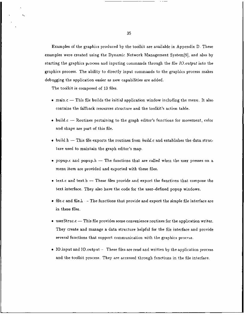
Examples of the graphics produced by the toolkit are available in Appendix D. These
examples were created using the Dynamic Network Management System[9], and also by
starting the graphics piocess and inputing commands through the file IO.output into the
graphics process. The ability to directly input commands to the graphics process makes
debugging the application easier as new capabilities are added.
The toolkit is composed of 13 files.
" main.c - This file builds the initial application window including the menu. It also
contains the fallback resources structure and the toolkit's action table.
* build.c - Routines pertaining to the graph editor's functions for movement, color
and shape are part of this file.
" build.h - This file exports the routines from build.c and establishes the data struc-
ture used to maintain the graph editor's map.
* popup.c and popup.h - The functions that are called when the user presses on a
menu item are provided and exported with these files.
" text.c and text.h - These files provide and export the functions that compose the
text interface. They also have the code foi the user-defined popup windows.
" file.c and file.h - The functions that provide and export the simple file interface are
in these files.
• userStruc.c - This file provides some convenience routines for the application writer.
They create and manage a data structure helpful for the file interface and provide
several functions that support communication with the graphics process.
" IO.input and IO.output - These files are read and written by the application process
and the toolkit process. They are accessed through functions in the file interface.

36
* X.title - The user puts the string to be displayed as the title in this file before
starting the application.
These thirteen files correspond to the components of the toolkit. The toolkit files were
arranged this way to enable the code to be more easily maintained. The C code in these
files has many comments and was written to be easy to understand.
The Network Graphics Toolkit has a very complicated inheritance structure.
to pleve 1
Shell Widget ,.
theViewport POPUP
Viewpart Widget Popup Widget
(inci 2 Scrollbars) a
oaDialog
theForm Dialog Widg t
Figu ormdTh Widget Tolk
TsnhBox Widget Set
Iury a i abl e Sc o lb
oCommand Widget
Figuree Lb Te Widget Str atue oft e ToLi
T h i s i n h e i t a c e s r u u r e o o k T h W i g e t h S t r u c t u r e o f e o l i c e i d e e

37
widget is a Shell Widget that was created with the XtApplnitialize function. It spawns
the Viewport Widget and the Popup Widget. The Popup Widget does not appear on the
screen. It serves as the parent widget to other widgets that appear temporarily to take
input from the user. The Viewport Widget gives the application the scrollbars that are
visible on the left edge and across the top and displays the Form Widget. Figure 4 shows
the graphics produced when the toolkit is initially called.
|Load Hot File ISave Network PriLt Not ListI Logging dd Conponen 1 elete Conpcxwent I Functions Q
This is a Sample Title From X.title
Figure 4: The Initial Graphics Produced by a Call to the Toolkit
The rest of the application is displayed upon the Form Widget. Near the top of this
Widget the menuBox is positioned. Directly under the menu is the title widget. The
invisible widget is created to make the scrollbars in the Viewport Widget work correctly.
38
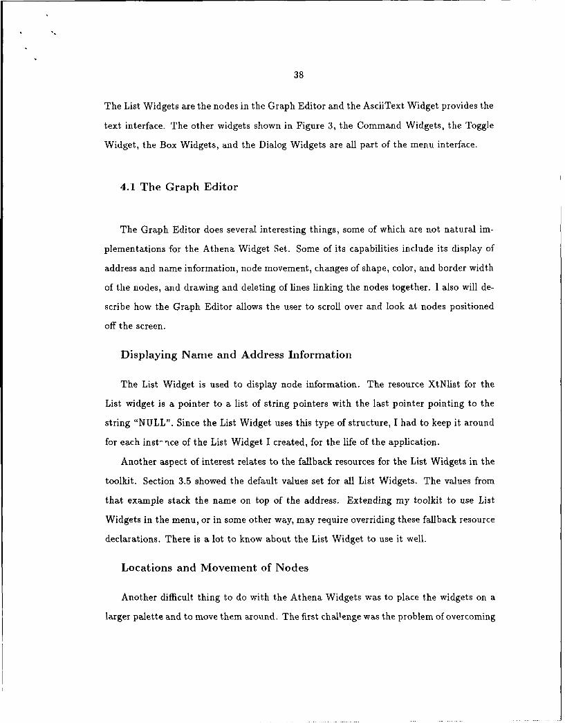
The List Widgets are the nodes in the Graph Editor and the AsciiText Widget provides the
text interface. The other widgets shown in Figure 3, the Command Widgets, the Toggle
Widget, the Box Widgets, and the Dialog Widgets are all part of the menu interface.
4.1 The Graph Editor
The Graph Editor does several interesting things, some of which are not natural im-
plementations for the Athena Widget Set. Some of its capabilities include its display of
address and name information, node movement, changes of shape, color, and border width
of the nodes, and drawing and deleting of lines linking the nodes together. I also will de-
scribe how the Graph Editor allows the user to scroll over and look at nodes positioned
off the screen.
Displaying Name and Address Information
The List Widget is used to display node information. The resource XtNlist for the
List widget is a pointer to a list of string pointers with the last pointer pointing to the
string "NULL". Since the List Widget uses this type of structure, I had to keep it around
for each inst-ice of the List Widget I created, for the life of the application.
Another aspect of interest relates to the fallback resources for the List Widgets in the
toolkit. Section 3.5 showed the default values set for all List Widgets. The values from
that example stack the name on top of the address. Extending my toolkit to use List
Widgets in the menu, or in some other way, may require overriding these fallback resource
declarations. There is a lot to know about the List Widget to use it well.
Locations and Movement of Nodes
Another difficult thing to do with the Athena Widgets was to place the widgets on a
larger palette and to move them around. The first challenge was the problem of overcoming

39
the Widget Set's propensity for resizing and relocating Widget children to use as little
screen space as possible. After trying several types of widgets in several different ways I
settled on the Form Widget as the palette on which to put the other Widgets.
The toolkit breaks a few rules to make the Form Widget work the intended way. The
Athena Widget Set documentation describes a phenomenon called Screen Flash, where
the widgets appear one at a time on the screen because the parent widget is made visible,
(Realized in Athena Widget terminology), before all the children have been created. Gen-
erally the widget writers thought that this phenomenon should be avoided. The problem
is that the Realize function always calls the Form Widget's internal Resize procedure. This
procedure packs the existing children of the Form Widget as close together as possible and
shrinks itself to the size of the minimum enclosing rectangle encompassing all its children.
This was unacceptable for a graph editor. To keep the Form Widget from calling this
procedure, the Form Widget was created before its children. These children include the
widgets that make up the menu and those List widgets that make up the nodes in the
Graph Editor.
The Form Widget has the ability to let its children set their location within the Form
Widget using the horizDistance and vertDistance resources. The Form Widget provides
these resource fields for each of its children. In the toolkit the children of interest are the
List Widgets. To set the location of each List Widget with respect to the top-left corner
of the Form Widget, the program must set the horizDistance and vertDistance as well as
the child widget's own x and y resource values. The x and horizDistance parameters and
likewise the y and vertDistance parameters must always be the same or the graph editor
does not behave correctly. The List Widget's other inherited resource values left., right, top
and bottom must be set to ChainLeft and ChainTop to insure that resizing the application
window does not change the nodes sizes, or their relative locations. Considerable time
was spent working through the Form Widget to get it to work the desired way.
Making movement work properly was also difficult. The movement function was broken

40
up into a three step process and functions called Start, MoveHosts, and Commit were
written. The X lib functions XGrabPointer and XQueryPointer were used to get the
pointer location and to return the window the mouse was clicked in. The MoveHosts
function can be modified to implement the shadowing of windows similar to the way of
Tom's Window Manager. The Commit function sets the window down in the new location.
These functions are called through callback routines set when the nodes are created. Also
Translation Tables and Action Tables are used to tie the mouse clicks to these functions.
There may be a way to use a widget like the poorly documented Grip Widget to do some
of the things that the X lib functions or the Translation or Action Tables do to connect
widget movement to mouse movement.
Variable Node Shapes
The Athena Widgets offer great potential to reset shapes and sizes. The sizes of the
widgets are dependent upon the font size and amount of the text, and the widget width
and height. The font can only be set in the fallback resources. The current font for the
nodes is a small, but readable, boldface-font. Reducing the font size reduces the size of
the widget. Another way to change the size of a widget is to set the width and height
parameters, called the internalWidth and internalHeight parameters in the List Widget.
These parameters can be set using the XtSetValues(widget, arglist, number) function once
the argument list is set up. This is outlined in Section 3.4.
Under X11R4, the widgets support the shape converters Xm.uShapeRoundedRectan-
gle, XmuShapeOval, and XmuShapeEllipse. Currently the toolkit implements rectangles,
rounded rectangles (with a ten-pixel rounded corner), ovals, and ellipses. No capability yet
exists within the Athena Widgets for drawing triangles, pentagons, hexagons, etc. How-
ever by resetting the widths and heights of widgets and by using these shape converters,

41
any rounded or rectangular shaped object can be made.
Setting Node Colors and Border Widths
The colors used in graphical interfaces are important for their user appeal. This ap-
plication insures that the foreground and background colors always contrast on nodes and
buttons. If they do not contrast well, displaying color graphics on a monochrome monitor
can be a problem. In the Athena Widget Set, the Command, Label and Toggle Widgets
are all written so the the foreground and background colors automatically maintain good
contrast. The graph editor currently uses three background colors, white, light-green
and red. It also uses two foreground colors in the nodes, blue for white and light-green
backgrounds, and white for red backgrounds. This provides an appealing contrast in color
graphics workstations and strong contrast on monochrome workstations. It is a very sim-
ple matter to expand the function ChangeColors in the file build.c to include a multitude of
other colors in the interface. These colors can be set on creation and changed on demand.
The Graph Editor also provides the user the capability of setting the border widths.
Currently the Graph Editor displays a node's border width as either one-pixel wide or
three-pixels wide. This is set by the application through series 206 messages to the toolkit
process. Currently the UW Dynamic Network Management System uses the variable
border widths to indicate whether the application is actively monitoring a node (wide
border) or not (narrow border). This gives the user yet another means to distinguish
nodes from one another.
Line Drawing
Another capability that my graph editor offers is the capability to draw and delete
lines. The application uses the 202 series messages to draw a line and the 203 series
messages to delete a line. It would be a simple matter to add variable line thicknesses
as well. The widgets redraw themselves when they become visible, though sometimes the

42
lines do not. The toolkit is written so that the lines redisplay themselves after a slight
delay when internal application windows are closed. Closing an occluding window external
to the toolkit, like an xterm window, will not send a redraw message to the lines, though
it does to the widgets in the toolkit.
Scrollbars
One last aspect of the Graph Editor is the ability to scroll so as to look at nodes that
are positioned off the screen. Normally the application will fill about eighty percent of the
screen in the X and the Y directions. However, by using a window manager like twm the
display can be resized to take up more or less of the screen. Sometimes using all of the
screen is not enough for large networks. The toolkit allows large networks to fill up more
than one screen, providing a horizontal and vertical scrollbar for the user to see sections
of the palette not normally visible.
This was implemented by putting the Form Widget into a Viewport Widget. The
Viewport Widget normally provides its child widget a scrolling capability to look at all
objects displayed in its workspace. The only way to insure that the Viewport Widget
always has the capability to scroll at least one screenful to the right and down was to use
the following code.
x = ((XWidthOfScreen(XtScreen(theForm))*2.0) -1);y = ((XHeightOfScreen(XtScreen(theForm))* 2.0) -1);XtSetArg(arg[0], XtNhorizDistance, x);XtSetArg(arg[1], XtNvertDistance, y);XtSetArg(arg[2], XtNborderWidth, 0);XtCreateManagedWidget(" ", labelWidgetClass, theForm, arg,3);
The code appears in the main.c file inside the function SetScrollbarSize. It creates a
Label Widget that is positioned two screenfuls right and two screenfuls down on the Form
Widget. This Label Widget's border is invisible and the label is blank. This "Invisible
Widget" forces the scrolibars in the Viewport Widget to cover all the area from the origin
out to this widget. This method works very well though it's not an elegant method of
setting the scrollbars. I currently limit the scrolling capability to twice the screen size in

43
each direction. It is a simple matter to set the "Invisible Widget" farther over and down
allowing the toolkit to scroll over a much larger area.
4.2 The Menu Interface
The Menu Interface has several features that make the Graphics Toolkit easy to use.
First, the Main Menu deserves attention, as well as the ease of creating submenus and
popup windows to prompt the user. Second, the ability to point and click on buttons in
t .e prompts and on the nodes in the Graph Editor itself, the binding of the Return Key
to functions in the popup windows and the ease of typing in input at the prompt will be
discussed. Third, the General Purpose Popup Prompts deserve mention since they are a
means for the application program to get information from the user through the graphical
interface without changing the main menu. These features make the Menu Interface easy
to use.
The Main Menu
The Main Menu box currently has eight Command Widgets, or Command Buttons.
The menu box is designed to stretch nearly all the way across top of the visible part of
the palette when the program starts up. When activated with mouse clicks two sub-menu
boxes pop up. One menu box under Print Net List shows four options and Cancel and
the other menu box under Functions shows seven options and a Cancel button. These
pop dowii menus make it easy to add more menu options within the toolkit. Note that all
the boxes have explicit width and height parameters set with calls to XtSetArg. If buttons
were added to these boxes the size of these boxes would have to be increased. The other
buttons do the specific things that are stated on their labels: Load Net File; Save Net File;
Logging; Add Component; Delete Component, and Quit. All buttons except Quit prompt
for more specific information needed to pass along a complete message to the application

44
process. The button Logging is implemented as a Toggle widget with a special callback
routine added to prompt the user for a tie name when the user wishes to use a logging
process.
The Point and Click Interface
The Athena Command Widget allows users to invoke functions, called callback rou-
tines, by clicking on a button. This interface is not too hard to code.
Another technique uses the action table and the translation table to allow the user to
execute functions by clicking on other widgets. In the file popup.c several examples exist
where translation and action tab1 -7 are used to call another function using a mouse click.
In the function DeleteFromNetwork the following translation table is called:
char deleteTranslation[]="Btn2Up: OkDeleteAddress)";
Below is the code in DeleteFromNetwork that puts the translation action into each of the
desired widgets:
table = XtParseTranslationTable(deleteTranslation);for (i = 0; i .lt. myobj.numhosts; i++){
XtOverrideTranslations(myobj.myptrs[i] - hosts, table);}
This example parses the translation table so that it can be input into the structures of
each of the desired widgets. The XtOverride Translations function adds the translation to
each of the widgets, replacing any other translation that may exist for Btn2Up. Another
translation table was loaded into each node when it was created tying the function GetAd-
dress to the Btn2Down key click. GetAddress sets the value of AddressOfInterest to be
the name of the node that the button was clicked down on. Callbacks and the translation
and action tables provide the point and click interface.
The Athena Widget Set provides a Dialog Widget that can be customized to take input
either from the keyboard or by clicking on Command Buttons. These Dialog Widgets are
used to prompt the user for the input the application needs. The Dialog Widgets are very

45
closely tied to the fallback resources where several parameters must be set. Typically the
fallback resource parameters for a Dialog Widget look like these:
"*addDialog*label.resizable: True","*addDialog.value: ","*addDialog.value.translations: #override \\ KeyReturn: OkGetName(",
The first line specifies that the text block where the user types the information for the
application should be able to grow, limited only by the size of the enclosing popup prompt
box. The second line makes the contents of the text input box initially blank. Not setting
the .value parameter for a Dialog Widget would give a popup prompt without a block to
insert text. Text blocks are not necessary for boolean prompts. Boolean prompts are most
effective when the dialog box displays only a "True" and a "False" button. The third line
traps the carriage return and calls the function OkGetName. This lets the user hit the
carriage return rather than typing in the value and clicking on the Ok button to proceed.
Generalized Popup Prompts
The interface also has some functions that enable the application process to have the
toolkit display customized prompts for input. It pops up a box in response to a 102 style
message from the interface with the text string of the message as the label, returning the
response in the form of a 101 style message. This gives the application a means to easily
query the user without the necessity of altering the toolkit's popup.c file. This is a very
important tool application programmers can use to shield themselves from the complexity
of the Athena Widgets. This capability also could form a starting point to develop an
interface that can be completely determined and set up by the application process that
defines its own menu titles on startup rather than modifying the popup.c file.
A User-Defined Title
One last feature of the toolkit is the ability of the user to display a title of his or her
choice just below the menu buttons. The title appears in twenty point boldface type and

46
is centered just below the menu buttons. The user has the capability to set this parameter
by creating a file called X.title in the toolkit's directory, in which the user specifies a string
which is read as the title of the application. If no file X.title is present, then the title is
left blank.
4.3 The Text Interface
The Text Interface is a feature that enables the application to pass information through
the toolkit to the user. The messages are displayed in an eighty-character wide text
window that scrolls to let the user see the most recent messages and provides the user
with a scrollbar to scan for messages that may have scrolled off the screen. The text
window comes up on top of the visible portion of the window in a bright yellow color so
the user does not miss the messages.
The text window employs two methods to close the window. One method allows the
application to directly close the window without the user taking any action at all and the
other method pops up a small close button that the user must click to close the window.
The most desirable way to close the window is almost certainly to require the user to close
it himself. This insures that critical messages are not missed. Currently the text window
pops up right on top of the Graph Editor and it cannot be moved to another location on
the screen. This can be a little inconvenient or distracting for users. It may be possible
to reimplement the text window as a separate application level process, putting it under
the control of the workstation's window manager.
4.4 The File Interface
The File Interface is a general interface that enables multiple processes to communicate
easily. It works well because of the small bandwidth needed to pass information between

47
the application process and the graphics process. It uses the file IO.output to pass messages
from the application to the graphical interface and the file IO.input to pass messages from
the graphical interface to the application. The interface currently has thirty-eight different
codes representing different types of messages. These codes are outlined in Appendix
A and detailed in Appendix B. Appendix A is the specific interface set up between the
Dynamic Network Management System and this toolkit. Appendix B contains the toolkit's
man pages. These thirty-eight codes are easily expandable without making the interface
significantly more complicated. Extra effort could be placed on making the 100 and 200
series interfaces larger to include features like an expanded shapes library, widths for
lines, and a greater numbers of colors. Extending the graphical interface would involve
expanding a case statement in file.c and supplementing or writing the relevant functions
in build.c.
Another aspect of this application is the ability of the user to add functions to be
checked on a periodic basis. The CheckFiles function in the file main.c shows a simple
way to use the XtAppAddTimeOut function to allow non-X functions to run continuously.
void CheckFiles(){XtAppAddTimeOut(app -con, 100, CheckFiles, NULL);CheckForInput(;CheckForOutput();I
The function XtAppAddTimeOut, which was discussed in section 3.3, calls itself (since
it appears within CheckFiles) every 100 milliseconds passing along no other parameters.
Next it calls two functions defined in the toolkit, CheckForInput0 and CheckForOutputO .
These functions take and send information through the file system to enable the toolkit
to communicate with the application process. The XtAppAddTimeOut function allows
the X-server to give control to non-X processes. An implementation that directly adds
functions to the X-server could make the Toolkit more efficient.
Using a file interface has several significant advantages. First, with separate processes
the application is independent of the specific ADE used to display it. Second, the toolkit

48
can be developed and refined distinct from the application as long as the interface remains
the same. Third, the interface simplifies the applications development task since the
programmer is spared having to learn the details of some ADE.
4.5 The Data Structure and Naming Conventions
Understanding the toolkit's internal data structure and maintaining strict naming
conventions were very important in this toolkit's design and are important to keep in
mind as it is revised. Generally no data structure is required for Widget applications
since the widget tree and the internal resource variables of each widget provide sufficient
structure for typical applications. The hierarchical data structure for the nodes in this
toolkit's graph editor is required because there must be some means to identify nodes.
The file build.h details the data structure summarized below.
typedef struct {Widget hosts;List list;Connection *link;Place place;
} MyList;
The widget hosts is a List Widget which displays information from the XtNlist resource
variable. The location information as well as attributes like its shape, color, border width,
etc. are kept in internal variables of the widget. These variables are set and read through
argument lists created with XtSetArg calls, combined with the function calls XtSet Values
and XtGetValues with the argument list as a parameter.
The List structure is defined as:

49
typedef struct {char nm[16];char addr[16j;
} List;
This structure keeps the name and address information used by the functions in build.c
to compare names and addresses in the data structure. The address field must be distinct
for each node or the graphics process will produce unexpected results.
The Connection structure is defined below.
typedef struct connection {char linkname[16j; /* actually is the internet number */struct connection *next;
} Connection;
This structure is a linked list of other nodes that are adjacent to the current node. It
is implemented so that only the lexicographically smaller addressed connection keeps the
link. This minimizes the amount of time spent searching the list and drawing the lines.
The third data strt':ture is required so that the widget can access the information to
be displayed via the resource variable XtNlist:
typedef struct{char *nm;char *addr;char *empty;
}Place;
The first two variables point back to the List Structure's nm and addr fields and the
third variable points to the string "NULL". This structure is assigned to XtNlist for each
instance of the List Widget.
The top level data structure is implemented as a record consisti-g of an array of Mylist
structures and a field that keeps an index of the last valid MyList location in the array.
It is very easy to write Athena Widget applications that virtually no one can un-
derstand. Athena Widget applications are written in C and, when the peculiarities of
C-like global variables is combined with the Athena Widget's esoteric function calls to
four different libraries, the code can get difficult. It was written with a lot of discipline in

50
naming the widgets and the callback functions. The Toolkit uses the convention that the
translation table name, the action table name, and the callback function name all be the
same. Additionally, the fallback resources make repeated reference to a variety of Dialog
Widgets. These Dialog Widgets are actually used across two or three functions, but refer
to the same widget. By naming them with care in each function it is easier follow the
source code.
4.6 Using the Toolkit
Application programs will need to use routines like those found in userStruc.c for the
file interface. This file consists of routines to allow the application programs to open
IO.output to write information to be displayed by the graphical interface, and IO.input
to read and reset this file which passes user requests to the application. Typically the
IO.input file must maintain a long function with one or more case statements that parses
and determines the nature of the user's request. This case statement should have the
capability to handle all applicable FmIO requests. Additionally, the relevant ToO calls
have to be added to the body of the application calling the function AddToMessageBuffer.
Generally these procedures are not difficult for the programmer to implement.
Application programs will have to use a data structure to maintain information to
pass to the graphics process. Sometimes the need to maintain this data structure can be
demanding. The UW Dynamic Network Management System saves the Graph Editor's
state continuously and writes it to a file when the user clicks on the Save Network button.
Of course the user can load the previously saved file with the Load Net File button.
The file records a number of different variables like the node name, address, type, x and
y coordinates, operational status and monitoring interval. Keeping a good continuously
updated data structure is an absolute requirement if applications are to have the capability
to save their state from session to session.

51
This toolkit is implemented in such a way that nodes are created or deleted only after
receiving a message from the application. The user adds components by clicking on the
Add Component button and responding to the necessary prompts. This information is
passed by the toolkit to the application via the file system. The application does validity
checks and returns a message to the toolkit via the file system to draw a component
providing the information to be displayed within the node and its location. This keeps
the toolkit general enough to be used for other types of applications. One case where
the application automatically deletes nodes from the screen is when the user requests the
Toolkit to load a network file and another network file exists on the display. In this case
the graph of the nodes on the display are deleted from the screen before the new file is
put up on the display.
4.7 The Suitability of the Widgets
Creating this toolkit did more than just provide a smooth interface for network man-
agement applications. It also validated the utility of the Widgets for other major appli-
cations. Some X-Windows experts have dismissed the X-Athena Widgets as not really
anything more than a complicated set of routines built to be used in simple applications
like xterm, xedit, xload, and xmh. There were serious questions of the need to continue
to develop the Widget Set if their only practical use was to make a handful of programs
somewhat easier. This application shows that the widgets can be used for serious interface
design.
Now that we can consider the Athena Widget Set and The X Toolkit Intrinsics to be
a serious ADE, the quality of this ADE should be assessed. I first asked if this ADE was
capable of doing everything required for my application. The ADE was unable to produce
any shapes other than rounded or rectangular ones. Other capabilities like reading the
mouse coordinates and drawing lines also had to be done using the X lib. The designers
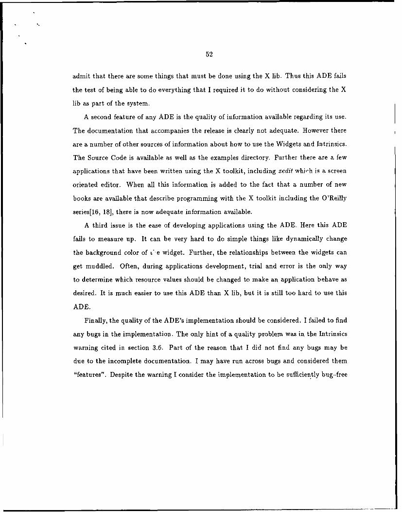
52
admit that there are some things that must be done using the X lib. Thus this ADE fails
the test of being able to do everything that I required it to do without considering the X
lib as part of the system.
A second feature of any ADE is the quality of information available regarding its use.
The documentation that accompanies the release is clearly not adequate. However there
are a number of other sources of information about how to use the Widgets and Intrinsics.
The Source Code is available as well as the examples directory. Further there are a few
applications that have been written using the X toolkit, including xedit whirh is a screen
oriented editor. When all this information is added to the fact that a number of new
books are available that describe programming with the X toolkit including the O'Reilly
series[16, 18], there is now adequate information available.
A third issue is the ease of developing applications using the ADE. Here this ADE
fails to measure up. It can be very hard to do simple things like dynamically change
the background color of L"e widget. Further, the relationships between the widgets can
get muddled. Often, during applications development, trial and error is the only way
to determine which resource values should be changed to make an application behave as
desired. It is much easier to use this ADE than X lib, but it is still too hard to use this
ADE.
Finally, the quality of the ADE's implementation should be considered. I failed to find
any bugs in the implementation. The only hint of a quality problem was in the Intrinsics
warning cited in section 3.6. Part of the reason that I did not find any bugs may be
due to the incomplete documentation. I may have run across bugs and considered them
"features". Despite the warning I consider the implementation to be sufficiently bug-free

53
for most applications.
4.8 Sunmmary
This chapter introduced the Network Graphics Toolkit. The graph editor part of the
toolkit can display a large number of nodes and links using a small font size, and scrollbars
to overcome the limitation on the screen size. The menu interface allows a point and click
interface using translation tables and action tables to limit the amount of input that the
user must type when prompted. The text interface sends messages to users from the
application and includes a scrollbar so the user can reexamine any message that may
have scrolled off the screen. The file interface provides an effective means of insuring that
two Unix processes can communicate and is very easy to implement. Finally the data
structure and the naming conventions should facilitate maintenance and expansion of the
toolkit. The Athena Widget Set is not ideal; it is a capable, though somewhat basic ADE.
It is a good place to start writing graphical applications given the lack of more advanced
development environments.
The next chapter will put the work that has been done on the Network Graphics
Toolkit into perspective. Two 1 Jgrarns that use the toolkit will be discussed, and the
suitability of the Athena Widgets and the X Toolkit Intrinsics taken together as an ADE
will be assessed.

Chapter 5Developing Applications with the Toolkit
The toolkit I developed using the Athena Widget Set has potential as a graphical
interface for a wide variety of network management applications. Two programs at the
University of Washington currently take advantage of it to display graphically their net-
work management programs. This chapter will examine both of these programs and
describe how they use it. It will also look at the application in a more general context,
considering other applications that can benefit from using all or part of the toolkit.
5.1 UW Dynamic Network Manager
The UW Dynamic Network Manager,[15] written by Walt Reissig, uses SNMP to
collect data for his program. It discovers the existence of hosts, routers and networks
and calls my program to display these nodes where his program indicates. The Dynamic
Network Manager uses nearly every aspect of my graphical interface. The nodes can be
either rectangle, rounded rectangle or ellipse shaped; the border widths can be either
narrow or wide; and the background colors of the nodes can be either red, white or green.
His program maintains the locations of the nodes as they are moved on the screen to
different positions. His program also directs my toolkit to add or delete nodes and links
in response to input received from the user via the toolkit's menu interface. This interface
55
was designed to be compatible with the capabilities of his program. Appendix A describes
all possible messages in the communications interface between our programs.
The use of my toolkit allowed Walt Reissig to concentrate on writing his application
rather than the graphical user interface. His concern was focused on giving his program
the greatest range of functions possible and less on how output was to be displayed. He
implemented a program that can discover systems adjacent to systems in his network;
that can monitor the operational status of nodes, and that can query a system for one or
more variables that are part of its SNMP database. Freeing him from the need to learn
the X lib or the Widgets and the Intrinsics gave him more time to concentrate on the
application itself.
5.2 Traceroute
Scott Murphy recently completed extending the public domain Tracetoute[26] program
to take advantage of the Network Graphics Toolkit. His program originally provided text
output that listed the route from the host computer to some remote host. The work that
he had to do to extend his program typifies the sort of work that users who wish to extend
non-graphical network management programs will have to do to give their programs a
graphics capability. He needed to develop an additional data structure to maintain the
links between the nodes as well as a structure to maintain the nodes. This was necessary
because he wanted to use the Load Net List and Save Network buttons to save and restore
the graph from session to session. The data structure also had to record the X and Y
coordinate locations of all nodes. To support the Logging button he implemented functions
to open, write to, and close a user-specified log file. He also implemented procedures to
add and remove nodes from his data structure in response to the toolkit's Add Component
and Delete Component buttons.
Murphy found that the ideal format for his program to get the name and the address of

56
nodes to trace was a little different than the toolkit's format. His program always begins
its route tracing from the host node, so that there was no value in clicking on the "from"
node as prompted by the toolkit's menu. Despite all the extra work, he is very satisfied
with the graphical interface of my toolkit. In the section on future directions for my work,
I will return to the issue of developing a method to let the user specify his own menu
interface.
Murphy's work validated the concept that non graphical programs can be given a
graphical interface without the application writer needing to begin using direct calls to
some ADE or the X lib. As a service, my toolkit provides the file interface that the
application writer needs (in the file userStruc.c). One interesting problem that Murphy
encountered was the fork procedure that first starts my process and then his process.
His application runs in kernel mode which is required for the Internet Control Message
Protocol (ICMP). It was not possible in the time available to come up with a means to
fork a process while in this mode. His implementation used separate xterm windows on
the same host, one for each process, to run his application's process with my graphical
process.
5.3 Separating the Graphics from the Application
Reissig's and my work make a strong case for the notion that a graphical programs
can be written that are independent of the graphical interface. This is significant in
that it makes application programs more transportable to other graphical ADEs as they
become available. Reissig's program could be easily implemented on a machine running
Motif, for example, as long as the functions in the toolkit were rewritten using Motif.
The notion of keeping the graphics distinct from the application gives the application a
lifespan beyond that of the interface for which it was developed. This is what writing

57
maintainable programs is all about.
5.4 Summary
This chapter has examined two different Network Management programs that were
written or modified to use the toolkit. The toolkit provided each of these programs
a good graphical interface and freed the applications programmer from having to get
involved in the details of the graphics. New graphical applications environments are being
developed that will add even better graphical capabilities for future programmers. These
two programs are able to make use of these new programs easily as long as the functions
in this toolkit are implemented by some future toolkit developer.
The next chapter will discuss several suggestions for future work using this toolkit as
the base. This toolkit was developed with network management applications in mind;
however, it can be exLended to support unrelated applications fairly easily.

Chapter 6Discussion of Future Work
The previous chapters presented the Athena Widget Set/ X Toolkit Intrinsics ADE,
laid out the work done with it to create the Network Graphics Toolkit, and presented
some applications that use the toolkit. This work has shown limitations in both the ADE
and the toolkit that can motivate future research.
Stepping back from the specifics of the implementation for a moment it is clear that
two broad ideas emerge. First, it is possible to create programs that are independent
of the graphics that implements them. Development of more sophisticated toolkits can
make programming much more efficient than currently possible with even the best ADEs.
Second, a more efficient communications interface can replace the current file interface,
which links the graphics and the application.
There are many applications that can benefit from this work. This chapter will discuss
some non-network management applications and propose further work appropriate to make
the toolkit more adaptable.
6.1 Using the Toolkit for Other Types of Applications
The toolkit has potential in several non-network management related fields. The
source code of the toolkit as a whole represents an example of a large widget-based appli-

59
cation. Since there are few of these available this toolkit can be valuable for programmers
as an example of how to do certain things.
The graph editor portion of my application, where I set and move nodes around with
mouse clicks, could be ideal as part of a Computer Aided Design Tool. There is also
some interest in writing programs that use graphics to simplify existing programs. For
example, an automated makefile program might be developed that allowed a user to make
a dependency graph of a set of files and produce an efficient makefile. It could be developed
using a different menu system and functions from the toolkit's build.c file. Parts of the
toolkit could be used for writing a program that creates a graph of a user's subdirectories,
allowing the user to move between them by clicking on nodes representing subdirectories.
In general, my graph editor overcomes the problem of widgets automatically resizing
themselves to take up the smallest possible screen size by using the Form Widget which
is made visible before any widget children of the Form Widget are created. Graphical
simulation applications that are unrelated to Network Management could also be written
to use my graphics since my program does not care what is represented inside the nodes.
They would probably require a different set of menu buttons to be adequately supported.
6.2 Further Refinements With the Athena Widgets
This section describes possible improvements and refinements of my toolkit. The most
significant improvement could come in the area of how the menus are specified. As it
exists right now the user must modify the file popup.c in the toolkit to change the menu
interface. The toolkit does provide the means to pop up custom labels to get information
from the user. This is a start to providing a more adaptable menu interface.
One way to implement a dynamic menu interface is to have a library of callback
functions that can be tied to menu buttons. A new code sequence could be added to
the file interface, perhaps 301 - 0, so the application can specify menu buttons to be

60
displayed by the toolkit, and the corresponding callback routine to execute when the
button is pressed. This code sequence would be sent to the file IO.output for each menu
button on program startup to build an application specific menu. For example, the user
could send a message to create an Add Component button and specify a callback routine
from the existing library for it. Without the benefit of some Graphical User Interface
Design Editor this solution may be as good as the menu interface can get.
There are a number of possible refinements to the graphics in the toolkit. Other
colors could be easily added to the ChangeColors function. Also widths of links could
be added. For variable widths of the links an integer type value would have to be added
to the Connection structure in the file build.h. This integer value could be the width of
the link to draw. A "for-loop" in the Redisplay Lines function is all that would need
to be added to accomplish drawing the variable width lines. Extra shapes could also be
added. Squares and circles are possible without too much trouble and really adventurous
X lib programmers could develop more advanced shapes. The ability of the lines to
automatically refresh themselves when they become visible can also be implemented. As
a hint for doing this, widgets all have routines called Redisplay( that restore the widgets
when they are exposed. Finally, the latest release of the Athena Widgets fixed a problem
in earlier versions in that bitmaps can now actually be displayed as promised. Having
small bitmaps available to put up inside the graph editor would further improve the look
of the graph editor or the menu buttons.
The toolkit could also be implemented using some event management function other
than XtAppAdd TimeOut. This function may create a race condition with the X server,
causing machine performance to suffer. The file interface is also something that could
be revised. Reissig's approach for process communication is effective and universal, but
is very slow. Another system could be developed to do the job much better although
the operating system independence of the program might suffer somewhat. Developing a
standard communications interface protocol, perhaps by using operating system dependent

61
stubs like those used in the Remote Procedure Call methodology can provide an efficient
yet portable solution.
Several other less significant possible changes will now be mentioned. It would be ideal
to include the ability to show the user an outline of the widget that is being moved from
one point on the screen to another as long the user holds the mouse button down. It would
also be helpful if the text widget could be a separate application level window under the
control of the window manager. This would permit the widget to be resized, iconified,
and moved about the screen. It mi.ght also be of value to implement code that removes
all connections to a node when the node is deleted rather than asking the application to
do it. Implementing a StripChart Widget similar to the text widget that could monitor
one or more variable by clicking cii the node would be desirable. These refinements can
all be implemented using the Athena Widget Set.
6.3 Conclusion
This thesis began with a discussion of the need for graphics applications for network
management, making the point that these graphics programs are hard to write. Chapter
1 continued with a discussion of the objectives of this thesis. The objectives were to
develop a toolkit to ease the creation of graphical network management applications.
Other objectives were to evaluate a number of graphical programs and assess the utility
of the Widgets and the Intrinsics as an ADE.
Chapter 2 discussed several graphical programs that embed their graphics code within
the application. This was contrasted with the goal of my toolkit to provide the user with a
high-level graphical interface that freed him from having to include ADE or X lib specific
code in the application. Only calls to high level routines should be necessary.
Chapter 3 discussed important concepts in the X Toolkit Intrinsics and the Athena
Widget Set and provided a general evaluation of the Widget Set's capabilities and its ease

62
of programming. It is not an ideal ADE but it is far better than using the X lib.
Chapter 4 discussed the implementation of the toolkit using the Athena Widget Set
and the X Toolkit Intrinsics. The toolkit has several major aspects. The graph editor
takes up most of the screen space of the application. It gives the user the ability to
reposition nodes on the display and uses variable color, shape and border width to provide
information about the nodes. The menu interface allows the user to query the application,
assigning it tasks to complete. The text interface allows the application to pass important
information back to the user. The file interface enables communication between the active
user application and the graphical interface. Finally, the internal data structure and
naming rules help insure that the graphical interface and the user application are consistent
and that the toolkit source code is as clear as possible.
Chapter 5 highlighted two programs that use the toolkit. They demonstrate its utility
though the graphics code is separate from the application code.
Further work needs to be done to refine this notion of keeping the graphical interface
code distinct from the applications code. The toolkit takes away from the applications
programmer the complete control over the screen and the application. The programmer is
given the right to choose from the available shapes, colors and border widths to display the
information relevant to the application. It offers ease of building an application and the
promise that the application can be moved to different ADEs as the technology continues
to progress.
This work can be continued in conjunction with the development of a formal commu-
nications interface. This interface can provide smooth communication between processes
without using visible files with permissive access controls.

Bibliography
[1] James Gettys, Robert W. Scheiffler, and Ron Newman, X lib - C Language X Interface,
MIT X Consortium Standard, X Version 11, Release 4, 1988.
[2] Chris D. Peterson, Athena Widget Set - C Language Interface, X Window System,
X Version 11, Release 4, 1989.
[3] Robert W. Scheffler, X Window System Protocol, X Version 11, Release 4, 1988.
[4] Dan Heller, "X View Programming Manual, An OpenLook Toolkit for X11",
Definitive Guide to the X WIndow System, Vol 7, O'Reilly and Associates Inc, Sebastapol,
Ca, 1990.
[5] Pamela Rockwell, "OSF/Motif Graphical User Interface", Datapro Reports on UNIX
Systems and Software, Datapro Research, Delran NJ, May 1990.
[6] Joel McCormack, Paul Asente, and Ralph R. Swick, X Toolkit Intrinsics - C Language
Interface, X Window System, X Version 11 Release 4, 1988.
[7] M. Fedor, et al., SNMP Network Management Station (NMS) and Agent
Implementation Version 4.0, NYSERNet Inc, 1989.

64
[81 David Martin, "MIT Network Simulator User's Manual", updated by Hellmut
Golde, Department of Computer Science and Engineering, University of Washington, 1989.
[9] Walter C. Reissig, "Dynamic Network Management Using the Simple Network
Management Protocol (SNMP)", Masters Degree Thesis, Department of Computer Sci-
ence and Engineering, University of Washington, 1990.
[10] Scott Murphy, "XTraceroute", Senior Project, Department of Computer Science
and Engineering, University of Washington, 1990.
[11] Chris D. Peterson, Xmu Library, X Window System, X Version 11, Release 4, 1989.
[12] Alan Southerton, "Many Paths to X Window Programming", UnixWorld, Vol 7,
No 5, May 1990, p. 83-87.
[13] David Rosenthal, "A Simple Xl Client Program -or- How hard can it really be
to write 'Hello World'?", USENIX Winter Conference, Feb 9-12, 1988, Dallas, p. 229-242.
[14] David Simpson, "Ys and Zs of the X Window System", Systems Integration, Vol.
23, No. 3, March 1990, p 37-42.
[15] Peter D. Varhol, "Creating Graphical Interfaces For Unix", Personal Workstation,
April 1990, p 88-92.
[16] Adrian Nye, "X lib Programming Manual for Version 11", The Definitive Guides
to the X Window System, O'Reilly and Associates Inc, Sebastopol, Ca, 1988.

65
[17] Robert W. Scheiffler, James Gettys and Ron Neuman, X Window System C Library
and Protocol Reference, Digital Press, Bedford, Mass, 1988.
[18] Adrian Nye, "The X Window System Protocol", UnixWorld, Vol. 6, No. 9,
September 1989, p 105-113.
[19] Eliezer Kantorowitz and Oded Sudarsky,"The Adaptable User Interface",
Communications of the ACM, Vloume 32, Number 11, November 1989, p. 1352-1358.
[20] Howard Baldwin, "Building Products on X", UnixWorld, Vol 7 No 5, May 1990,
p 88-95.
[21] Tom LaStrange,"twm", Unix Programmers Manual, BSD 4.3, Evans and Souther-
land, 1988.
[22] R. Stine ed., "A Draft Network Management Too! Catalog: Tools for Monitoring
and Debugging TCP/IP Internets and Interconnected Devices", SPARTA Inc., January
1990.
[23] Tony Hoeber, "The OpenLook Graphical User Interface", Datapro Reports on
UNIX Systems and Software, Datapro Research, Delran NJ, May 1990.
[24] Steven Mikes, X Window System Technical Reference, Addison Wesley, Reading,
Mass, 1990.
[25] Andrew S. Tannenbaum, Computer Networks, Prentice Hall, Englewood Cliffs,

66
New Jersey, Second Edition, 1988.
[26] Van Jacobsen, "Traceroute", University of California, Berkeley, 1988.

Appendix AThe Communications Interface
Type GrlntfcePgm File App PgmFmlO: 10 (X) to 10.input to I0mgrToJO: 1O (X) from IO.output from IOmgr
Types Commentschar ipaddr[16]; node address or LANchar nametype[33]; node or file namechar commid[16]; community namechar mstring[80]; general use string
Dir Vall Val2 Other Information
FmIO 1 - 0 nametypefilename
Load a file
FmIO 2 - 0 nametypefilename
Save network to file
FmIO 3- 1Print all nodes summary info
FmIO 3- 2Print all links summary info
FmIO 3-3Print all LANs summary info
FmIO 4 - 0 nametypefilename if turning on
Turn logfile on/off

68
Dir Vall Va12 Other InformationFmIO 5 - 0 ipaddr, nametype, commid
address, name, communityAdd a component
FmIO 6 - 0 ipaddraddress
Delete a component
FmIO 7 - 1 ipaddr, nametype, ipaddr, mstraddress, name, comm, MIBVar
MIB variable query of a node
FmIO 7 - 2 ipaddr, nametype, ipaddr, mstraddress, name, comm, MIBCat
MIB Category query of a node
FmIO 7 - 3 ipaddr, intaddress, interval(interval 0 is off)
Turn Performance Monitoring on/off
FmIO 7 - 4 ipaddraddress
Check Operational Status of a Node.
FmIO 7 - 5 ipaddr, mstringaddress, performance type
Analyze Performance.
FmIO 7 - 6 ipaddr, mstring, mstringRequires: address to map'm' to map 'c' to confirm
add only? "snmp" or any"l
Map or Confirm Neighbors.
FmIO 7- 7 ipaddr,nmtype,addr,nm,comm,intRequires: address of startnmtype- none always returnedaddress and name of endcommunity of endAdd to network - l=Yes, 0=No
Trace a Path between nodes.
FmIO 8-0Quit the program.

69
Dir Vail VaI2 Other InformationFmIO 0 - 1 ipaddr, int, int
addr, xcoord, ycoord
Move a node.
FmIO 0 -2 ipaddr, int, intaddr, xcoord, xcoord
Move a LAN.
FmIO 101 - 1 mstringstring data
Send reply to 102 type msg.
FmIO 101 - 2 intinteger
Send a reply to 102 type msg.
ToIO 102 - 1 mstringstring
Send msg to Screen, awaiting string reply.
ToIO 102 -2 mstringstring
Send msg to Screen, awaiting integer reply.
TolO 102 -3 mstringstring data
Send msg to screen, reply 0='N', 1='Y'.
ToIO 201- 1 addr,nm,int,int,int,intaddr, nm, snmp, oper, x, y
Draw gateway.
TolO 201 - 2 addr,nm,int,int,int,intaddr, nm, snmp, oper, x, y
Draw router.
ToIO 201- 3 addr,nm ,int ,int ,int,intaddr, nm, snmp, oper, x, y
Draw host.
TolO 201 - 4 addr,nm,int,int int,intaddr, nm, snmp, oper, x, y
Draw LAN,
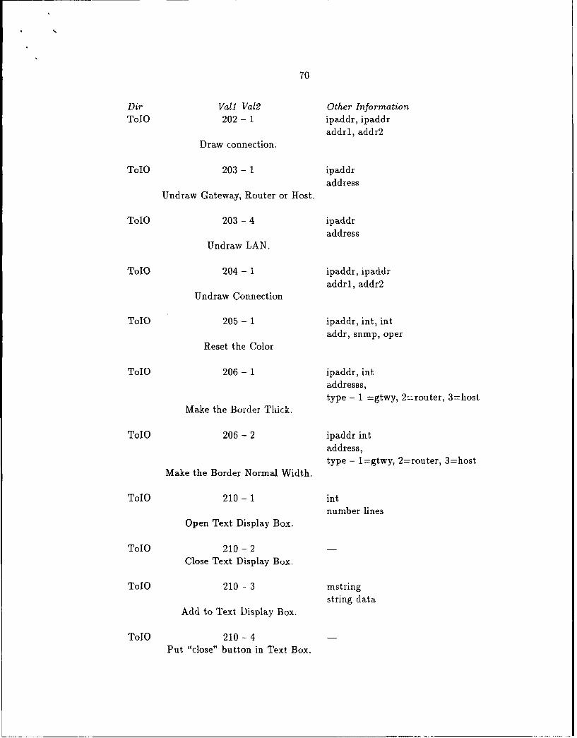
70
Dir Vall Val2 Other InformationToIO 202 - 1 ipaddr, ipaddr
addrl, addr2Draw connection.
ToIO 203 - 1 ipaddraddress
Undraw Gateway, Router or Host.
ToLO 203 - 4 ipaddraddress
Undraw LAN.
TolO 204 - 1 ipaddr, ipaddraddrl, addr2
Undraw Connection
TolO 205 - 1 ipaddr, int, intaddr, snmp, oper
Reset the Color
TolO 206 - 1 ipaddr, intaddresss,type - 1 =gtwy, 2=router, 3=host
Make the Border Thick.
ToIO 206 - 2 ipaddr intaddress,type - 1=gtwy, 2=router, 3=host
Make the Border Normal Width.
ToIO 210 - 1 intnumber lines
Open Text Display Box.
ToIO 210 - 2
Close Text Display Box.
ToIO 210 - 3 mstring
string dataAdd to Text Display Box.
ToIO 210 - 4Put "close" button in Text Box.

Appendix BThe Man Pages
NAME
U. W. Network Graphics Toolkit
SYNOPSIS
Xio
Xio -d -f -1 -m -p -t
DESCRIPTION
Xio starts up a process that creates a window which provides a point and click interfacefor network management applications to use. The current popup menu is sufficientfor most general purpose network management applications including performancemonitoring, simulation network discovery and node-status with little or nomodification. The Network Graphics Toolkit consists of a series of routines thatuses the X-Athena Widgets and the X-Library to create and display hosts andtheir connections in a consistant high-quality manner.
Network Graphics Toolkit takes input from an application program that it isanimating. It allows the application program to set node locations, colors of thenodes, border widths of the nodes, shapes of the nodes and to display the nodeconnections easily. The application program can also send warning messages to theuser using both general popup windows or moderately large text windows to getthe users attention. Further the Xio program is designed to act as a GraphicalUser Interface with mouse clicks and keyboard input changing the screenparameters and passing back instructions to an application process. Theinstructions for an application program are passed to the system through a mousedriven menu interface and a mouse-driven click-and-drag interface to move nodesaround to different screen locations. The mouse driven interface currently useseight main-level buttons, though expandable to more buttons. Some of these menubuttons open up to display nested menu buttons under these main menu buttons.
The Network Graphics Toolkit includes the capability to have the application popup additional menus to exchange information between the user and the applicationprocess. These General Purpose Popup Windows have customizable labels andallow the user to input with the keyboard or click with the mouse to communicatewith the application process. The Network Graphics Toolkit also uses scrollbars toallow the user to examine networks that may be much larger than what could becomfortably put on one screenful of a workstation.

72
The Source Code provides examples of how to write other procedures for differentmenu boxes and popup prompts. The program might be started on a Unixmachine by forking off a process from the user's application program thatinitializes the interface and sets up the menu boxes. If the process that forks offthe Xio process also specifies one of the flags above, for example, '-d' the windowthat starts up the application program gets debugging information. In general eachstart up option provides a different type of debugging information.
OPTIONS
-d Provides standard debugging information specifically related to the filesmain.c and build.c and includes the operations that manipulate the datastructure that holds the widgets.
-p Provides debugging information relating to the UW Dynamic ManagementApplication menu interface. The Menu Button and Popup Window activitiescan be easily monitored with this flag set.
-t Provides debugging information for the text window interface.
-m Provides debugging information pertaining to the movement of the nodeswith the pointing device.
-1 Provides debugging information pertaining to the line drawing and line erasingfeatures of the program.
-f Provides debugging information about the file system interface.
The large title that appears centered below the menu buttons can be set by creating afile called X.title and putting the desired title in that file. On program start-up theprogram reads the string found in this file and displays the string while theNetwork Interface is running. Currently this string is not resettable during the lifeof the process.
The Graphical Toolkit communicates with the network management applicationprocess through the Communications Interface. The Communications Interfaceconsists of the files IO.input and IO.output. The code phrase FmIO means that theuser application is getting input from the toolkit. This happens through the fileIO.input, and the messages generally are requests for services. The phrase ToIOmeans the file IO.output is the conduit for messages from the application to thegraphical interface and are usually requests for the application to displaysomething.
IO.input and IO.output must be pre-existing before starting the Xio process andhave both the 'read' and 'write' permissions set. To allow others to runapplications out of your directory on a Unix based system, these files must havegroup and/or world permissions 'read' and 'write' permissions set.
FmIO: Xio through IO.input to Application.ToIO: Application through IO.output to Xio.

73
Types Comments
char ipaddr[161; node address or LANchar nametype[33]; node or file namechar commid[16]; community namechar mstring[80]; general use string
Dir Vall Val2 Other Information
FmIO 1 -0 nametype
filenameTells the Application to Load the specified file,
clears the palette of any displayed nodes, andinitializes the data structure that maintains thenodes while they are on the screen. Activated by
clicking on the Load Net File button andtyping a filename. If the file exists, theapplication sends 201 and 202 series messagesin reply.
FmIO 2-0 nametype
filenameTells the Application to Save the Network on thepalette to a specified file. Activated by clickingon the Save Network button and typing afilename. Application does not reply.

74
Dir Vall Vd!2 Other Information
FmIO 3- 1Print all node summary info in the text window.Activated by clicking on the Print Net Listbutton then on the ... nodes button on thebox that pops up. Application sends several 210
series messages to the display.
FmIO 3-2Print all link summary information. Activated byclicking on the Print Net List button thenon the ... Links button on the next box. Theapplication uses several 210 messages to send back
the information.
FmIO 3-3Print all LAN summary information. Activated byclicking on the Print Net List button
then on the ... LANs button on the next box.The application uses several 210 messages to returnthe information to the display.
FmIO 4-0 nametype
file if turning onTurn logfile on/off. Activated by clicking onthe Logging button and typing in the filename.Application does not reply, instead the interfaceuses a toggle widget which shows reverse videowhen a log file is on.
FmIO 5-0 ipaddr, nmtype, commid
address, name, commClicking on the Add Component button and typingin the above information at the prompts sends themessage to the application. The application respondsby returning 201 and 202 series messages if the nodeis valid.

75
Dir Vall Val2 Other Information
FmIO 6-0 ipaddraddress
Delete a Node. Activated by clicking on the DeleteComponent button and then by obeying the prompt toclick on the node to delete with the second pointerbutton. The application responds by first deleting allconnections to the node then by deleting the node.
FmIO 7- 1 ipaddr, ipaddr, mstraddr, comm, MIBVar
MIB Variable query of a node. This message is sentwhen the functions button,then theQuery an
SNMP Variable button is clicked, then the otherinformation is typed in at the prompts. Theapplication replies with a series of 210 messages.
FmIO 7 - 2 ipaddr, ipaddr, mstraddr, comm, MIBCat
MIB Category query of a node. This message is sentwhen the functions button,then theQuery anSNMP Category button is clicked, then the otherinformation is typed in at the prompts. The UWDynamic Management Application replies withseveral 210 messages.
FmIO 7 - 3 ipaddr, intaddress, interval
Turn Performance Monitoring on/off. This messageis sent when the Turn Monitor on/off button isclicked within the Functions menu. Theinterval value 0 is off. The applicationwill send a 206 message if the 'Is Monitoring?'status changes between on and off, and will send a205 message if the operational status is different.The 205 message will be sent as long as 'Is Monitoring?'is on and the operational status changes.
FmIO 7 -4 ipaddraddress
Check Operational Status of a Node. This is a one-timeone-time check of the operational status of a node.A series of 210 messages and if necessary a 205 messageis sent in reply by the application.

76
Dir Vall Val2 Other Information
FmIO 7 - 5 ipaddr, mstring
address, performance typeAnalyze Performance. Not Implemented.
FmIO 7- 6 ipaddr, mstring, mstring
address, Map?, SNMP?Map or Confirm Neighbors. This is implemented byclicking on the Map or Unmap a Node button andclicking on the node of interest and the otherbuttons in the series of prompts. As implemented inthe UW Dynamic Management Application it mapsnodes adjacent to the node of interest or confirmstheir neighbors. Usually a series of 210messages are also returned. For Map the interfacereturns 'm' to map 'c' to confirm. For SNMP thevalues are "snmp" or "any".
FmIO 7 - 7 ipaddr, nmtype, ipaddr,
nmtype, commid, intaddr, name, addr,name, community, Add?
Trace a Path between nodes. Implemented byclicking on the Trace a Path Between Nodesbutton and then on the start node, and typing in theend node information. It can add nodes to the graph,but is implemented in the UW Dynamic ManagementApplication by returning the information to the uservia a series of 210 messages. The community is thecommunity ID for the end node. Add is a C booleantype value. The first nmtype value always is none.
FmIO 8-0
Quit the program. Sends ti s message, then theprocess terminates.
FmIO 0- 1 ipaddr, int, int
addr, xcoord, ycoordMove a node. This message sends the new X and Ycoordinate location of the upper-left edge of the node.This keeps the location of the nodes on the screenconsistant with the location of the nodes in theapplication.

77
Dir Vail Vai2 Other Information
FmIO 0- 2 ipaddr, int, int
addr, xcoord, xcoordMove a LAN. This message sends the new X and Ycoordinate location of the upper-left edge of theenclosing rectangle of the LAN. The application andthe screen will always have the same LAN locations.
FmIO 101 - 1 mstring
string dataSend a string reply to 102 type msg. This tellsthe user that the string came from the generalpopup prompt it sent earlier.
FmIO 101 -2 int
integerSend a reply to 102 type msg. Both boolean andinteger values can be represented with this msg.
ToIO 102 - 1 mstringstring
Send mnsg to Screen, awaiting string reply. Th!creates a popup prompt with the string as the lab-!and a window for the user to type in the informationrequested. iThe popup window is normally positionednearly centered in the application window. Theuser's reply is returned using a 101-1 message.
ToIO 102 - 2 mstringstring data
Send msg to Screen, awaiting integer reply. Thiscreates a centered popup window with the string asthe label for the popup window and a section forthe user to type in a integer value. The reply isreturned to the application using a 101-2 n,-ssage.
TolO 102 - 3 rnstringstring data
Send msg to screen, repl, 0--'No', I='Yes'. Thiscreates a centered popu i, window with the string asthe label for the p)Opup window and two buttons forthe user to click as the reply. The reply isreturned to the application using a 101- 2 message.

78
Dir Vall Va12 Other Information
ToIO 201- 1 ipaddr,nmtype,int,int,int,intaddr, name, snmp, oper, x, y
Draw gateway. This information is used by theinterface to draw a rectangular box with the 'addr'and 'name' strings inside. If snmp=O it's white.
If it's operational (oper= 1) its green, else it'sred (oper = 0). On a monochrome monitor red isreverse video. The y and x values are the pixelvalues to offset the nodes from the upper-leftcorner. The palette is larger than the screen andhas scrollbars so that integers larger than thedimensions of the screen are acceptable parameters
for x and y. Negative numbers are not acccptablcvalues for x and y as currently implemented.
ToIO 201 - 2 ipaddr,nmtype,int,int,int,int
addr, name, snmp, oper, x, yDraw router. Currently this is implementedidentically as the 201-1 message.
ToIO 201- 3 ipaddr,nmtype,int,int,int,int
addr, name, snmp, oper, x, yDraw host. The parameters are implementedthe same as in the 201-1 message. Thefunction implements a rounded rectangle asthe shape for these host objects.
ToIO 201 - 4 ipaddr,nmtype,int,int,int,int
addr, name, snmp, oper, x, yDraw LAN. The parameters are implementedthe same as in the 201-1 message. Theshape is converted to an ellipse with the
horizontal axis elongated.
ToIO 202 - 1 ipaddr. ipaddr
addrl, addr2Draw connection. This draws a single-pixelwide line between two 201 type objects. Thelines are drawn on the palette itself a.pdalways appear under the nodes.

79
Dir Vall Val2 Other Information
ToIO 203 - 1 ipaddr
addressUndraw Gateway, Router or Host. This messagedeletes the node. Currently it is importantto delete all links to the node before
deleting the node.
TolO 203 - 4 ipaddraddress
Undraw LAN. This message deletes the LAN.
Currently it is impoitant to delete all theconnections before deleting the node.
ToIO 204- 1 ipaddr, ipaddraddrl, addr2
Undraw Connection. Deletes the connection
between the nodes.
TolO 205 - 1 ipaddr, int, intaddr, snmp, oper
Reset the Color. It does not directly changethe node color to what the user specifies,instead it sets it through the integer parameters.snmp=0 - white, oper=0 - red, and oper=1 - green.
Other colors can be set or added by modifying theSetColors function in build.c using the integerparameters to encode the extra information touse these colors.
TolO 206 - 1 ipaddr, intaddresss, type
Make the Border Thick. This is used in theUW Dynamic Management Application to specifythat a node is being monitored, though otheruses in other aplications are possible. Theborder width is set from one-pixel tothree-pixels with this call. The integer value'type' is necessary since the objects must be
restored to rectangular shapes before the borderwidth can be altered, once the border is widened
their shape is restored. Type values are 1 (gtwy),2 (router)both square, 3 (host) rounded rectangle,4 (LAN) ellipse.

80
Dir Vall Val2 Other Information
TolO 206 - 2 ipaddr intaddress, type
Make the Border Normal Width. This restores theborder width on the nodes back to one-pixel.Type values are same as in 206-1.
ToIO 210 - 1 intnumber lines
Open Text Display Box. This pops up a yellow textbox that is about eighty characters wide with avertical scrollbar just above the bottom of theapplication window. The height of the box is setto be approximately the number of lines of theinteger parameter passed in. The application mustinsure only one window is open at a time.
ToIO 210 - 2Close Text Display Box. This closes the text boxwithout warning the user. Currently using the210-4 closing technique is more common.
ToIO 210 - 3 mstring
string dataAdd to Text Display Box. This adds one line oftext at the index position of the text window.Thus the text is appended to the tail of any textalready displayed and the text is scrolled upwardas new lines are added.
ToIO 210 - 4Put "close" button in Text Display Box. Thislets the user decide when to close the text windowonce the application finishes sending informationto the screen.
The application process that takes advantage of this graphical interface has to be ableto work within this communications interface. Typically the programmer will haveto write a set of procedures that open read and write the files. When the file hasbeen read the application jijarks the file as read. In this implementation this isaccompuished by making the first entry in each file be the number of valid entriesin the file. As one process writes messages into the open file it writes the numberof valid messages in the file in the first line. Once the receiving process reads the

81
file it resets the rnumber of valid messages in the file back to zero. The file file.cshows a number of these reading and writing procedures. The communicationsinterface is expandable and may include a nuimber nf other rossible messages. Thppossibilities are limited only by the imagination of the application writer and hisinterest in writing graphical routines that do what he desires.
To use the Graphical Toolkit the programmer will have to write a procedure thatprocesses the FmIO messages coming from the IO.input file and calls the correctroutines to handle each of these messages. Also the application will need to havecalls to a file handling routine that writes the appropriate messages and strings tothe IO.output file in accordance with the ToIO messagos.

Appendix CSummary of the Widget Set
Fundamental Widgets
Core Widget - The source code available in the Intrinsics. This is the widget that all
other widgets are subclassed from.
Shell Widget - The source code is available in the Intrinsics. This widget forms the
root of the tree. It is created by the XtApplnitialize X toolkit call.
Template Widget - This is the standard form to use for subclassing widgets. This
widget has no representation its only use is as the starting point to edit from to create
your own widgets.
Simple Widgets
Command Widget - This widget shows a label that when the left button of the mouse
is pressed upon it. It also reverses its foreground and background colors momentarily to
show it has been activated. The programmer specifies a callback routine to be executed
upon activation.

83
Grip Widget - It is defined to be a small rectangular region in which events like But-
ton Press can be handled. Can be used as an attachment point to reposition an object.
Label Widget - This widget shows a label on the screen. No callback routine can be
attached to it and it will not change color when the mouse is clicked on it.
List Widget - Allows the display of multiple lines of text. Has the capability to allow
each line to become active (acting like a separate Command Widget).
Scrollbar Widget - This widget is used with the mouse to move scroll around in win-
dows. They are frequently add-on features for the composite widgets defined below.
Simple Widget - This is the common superclass of the other Simple Athena Widgets.
It has no representation on its own but adds to them all variables that set their sensitivity
state and cursor shape.
StripChart Widget - This widget provides a real time graphical chart of a single
value. It reads data from an application and updates the chart at a specified interval.
Toggle Widget - This widget is much like a Command Widget except that it does
not restore the foreground and background colors that are switched with each activation
of the toggle. It maintains boolean state for the application.
Menu Widgets
Sme - Simple Menu Entry object, is the base class of objects from which the menus
are built. It defines no visible label.

84
SmeBSB -This menu entry object provides a selectable label. It also allows a bitmap
to be placed in the margins.
SmeLine -This provides an unselectable line that can be used to separate menu en-
tries.
SimpleMenu Widget - This widget is a container for menu entries. It is created with
the XtCreatePopupShell function call.
Menu Button Widget - The Menu Button Widget is like the Command Widget in
that its border is highlighted as the mouse moves over the window and it momentarily
changes colors when activated. It is used inside the Simple Menu Widget.
Popup Widget - The source code for this is provided in the X Toolkit Intrinsics sec-
tion. It provides a temporary shell that any widget can use for menus, text display, etc.
It has no graphical representation.
Text Widgets
AsciiText Widget - This Widget provides a standard ascii text based screen editor.
This is meant to be a polished implementation usable without changes.
AsciiSrc Object - This provides a link to a file or string so that this data can be read
into a structure for display on the screen.
AsciiSink Object - This object allows for information in the structure to be rendered

85
on the screen.
Text Widget - This is the parent widget of the AsciiText Widget. It is meant to be
subclassed for specific editing applications.
TextSrc Object - This is the root object for all text sources.
TextSink Object -This is the root for all text sinks. Any new sinks should be sub-
classed from this one.
Conposite and Constraint Widgets
Box Widget - This widget acts as the container for other widgets. It will always pack
its children as tightly as possible into non-overlapping row.
Dialog Widget - This is used for getting input from the user. It includes an optional
text input widget and has method to add button and callback routines.
Form Widget - This layout widget lets the children specify their positions relative to
each other or to the edge of the Form Widget.
Paned Widget - This allows children to be tiled horizontally or vertically, similar to
the panes in a window. The user can dynamically resize the individual panes.
Viewport Widget - This consists of a frame with one or two scrollbars and an inner
window. Applications larger than the current use scrollbars.

Appendix DExamples of the Toolkit's Graphics
LeOd ML File Saw Network Iprint Not ListI Loenn 1add Com.poent I 0.1st. Canponw*, FunctiswQut
DYE Dynamic Network Xanagmnt system
-. US .s1
2in.U 145
U~~u.in. 2 a. L W2

87
Load Net File Save Netwaork Pit $let ListLtogginf JMd Cowpoent Ieee Cnp Que~ry an SNHP variabe
Queryi an 51W catecoraThis is user defined with X title Thr intrOn/Off
hek peaional Stalus
flap or Unnap a Node
Cck 2nd giA.Lan an Node to hapCancel
553. 555. 55 5
13459.799. 18
IMA. 69.9~ 11222.233344
IThis is the text display box.


![RESEARCH Open Access Transcribing Bach chorales: Limitations and potentials … · 2017. 8. 29. · Soft computing techniques such as the Bayesian approach [4,8,11,19,22] graphical](https://img.pdfslide.us/doc/110x75/60f67c0677417f3775199fee/research-open-access-transcribing-bach-chorales-limitations-and-potentials-2017.jpg)