Embed Size (px)
Citation preview
14 January 2014 Report #: ANM-112N-13-05
CASTING FACTORS
Abstract
The issue of casting factors has been the object of numerous publications over the past several decades, and the debate on why they are imposed in the Federal Regulations (FARs) still rages on. To date, however, there is no consensus as to their origin(s). There is even confusion as to how these factors should be integrated with the other design parameters. Adding to the confusion is that the requirements pertaining to design property values and casting factors vary from one part of the FARs to the other; in fact, some parts are altogether devoid of such requirements. Where requirements exist, they are presented in a manner that is not easy to follow, and some requirements appear out of touch with design realities, even illogical.
The available historical documents indicate that casting factors find their roots in the use of separately cast test specimens for casting acceptance testing. Other views expressed in the literature are thought to be invalid.
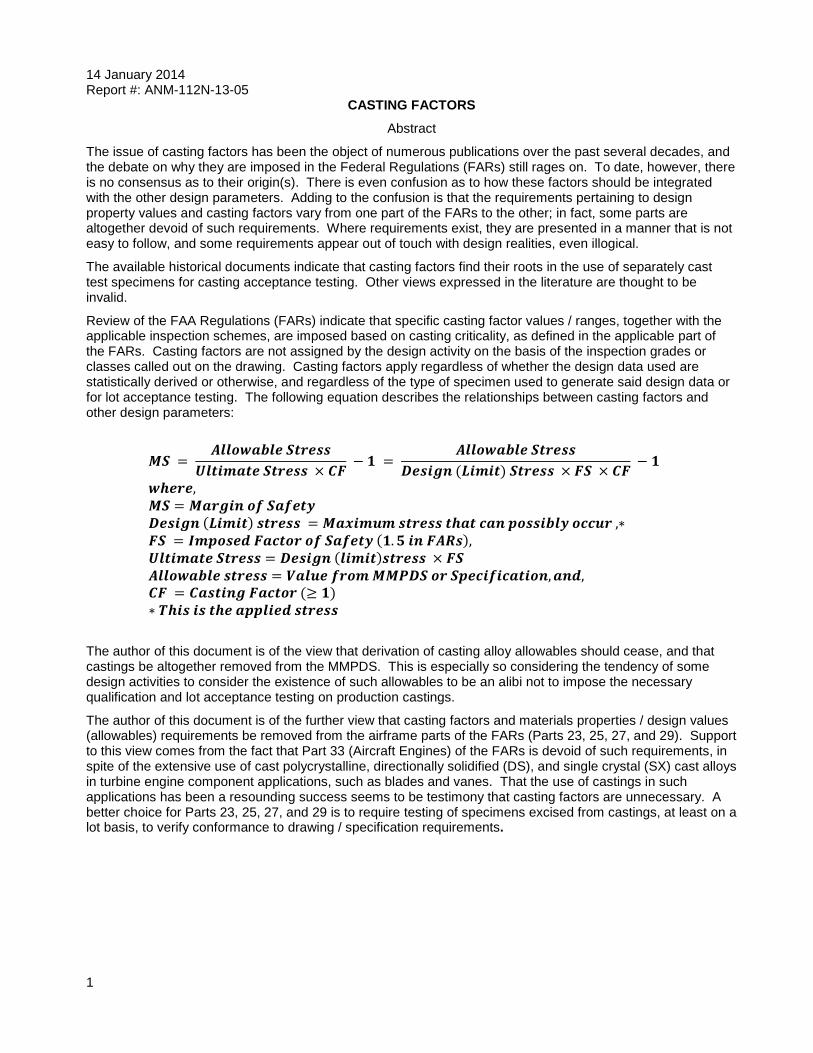
Review of the FAA Regulations (FARs) indicate that specific casting factor values / ranges, together with the applicable inspection schemes, are imposed based on casting criticality, as defined in the applicable part of the FARs. Casting factors are not assigned by the design activity on the basis of the inspection grades or classes called out on the drawing. Casting factors apply regardless of whether the design data used are statistically derived or otherwise, and regardless of the type of specimen used to generate said design data or for lot acceptance testing. The following equation describes the relationships between casting factors and other design parameters:
The author of this document is of the view that derivation of casting alloy allowables should cease, and that castings be altogether removed from the MMPDS. This is especially so considering the tendency of some design activities to consider the existence of such allowables to be an alibi not to impose the necessary qualification and lot acceptance testing on production castings.
The author of this document is of the further view that casting factors and materials properties / design values (allowables) requirements be removed from the airframe parts of the FARs (Parts 23, 25, 27, and 29). Support to this view comes from the fact that Part 33 (Aircraft Engines) of the FARs is devoid of such requirements, in spite of the extensive use of cast polycrystalline, directionally solidified (DS), and single crystal (SX) cast alloys in turbine engine component applications, such as blades and vanes. That the use of castings in such applications has been a resounding success seems to be testimony that casting factors are unnecessary. A better choice for Parts 23, 25, 27, and 29 is to require testing of specimens excised from castings, at least on a lot basis, to verify conformance to drawing / specification requirements.
1
1.0 INTRODUCTION
The issue of casting factors has been the object of numerous publications over the past several decades, and the debate on why they are imposed in the Federal Regulations (FARs) still rages on. To date, however, there is no consensus as to their origin(s). There is even confusion as to how these factors should be integrated with the other design parameters. Adding to the confusion is that the requirements pertaining to design property values and casting factors vary from one part of the FARs to the other; in fact, some parts are devoid of such requirements. Where requirements exist, they are presented in a manner that is not easy to follow, and some requirements appear out of touch with design realities, even illogical.
It would be beneficial, therefore, to review the casting factor topic one more time, to investigate, and, where possible, clarify the aforementioned issues. The purpose of this document is to do just that. Section 2.0 presents a concise summary of the requirements pertaining to design values and casting factors, as they appear in the various parts of the FARs (January 2012 issue). Where appropriate, the requirements are analyzed and critiqued. Section 3.0 presents equations and definitions pertaining to the casting factors and their relationships to other design parameters, such as the factor and margin of safety, applied and allowable stress, and material properties. The issue of generating MMPDS allowables, for wrought and cast alloys, is presented in section 4. Section 5 compares the requirements for allowables and the specimens used to generate them in the MMPDS and FARs. Section 6.0 is a discussion of the findings, whereas the summary and conclusions are presented in section 7. A brief chronological history of casting factors is presented in a separate Appendix at the end, so as not to interfere with the flow of the main text.
2.0 FAA REGULATIONS-OVERVIEW
Title 14 of the Code of Federal Regulations (CFR)-Parts 1-59 contains the FAA Regulations (FARs) in Subchapter C-Aircraft (Parts 21-49, incl.). a Of these, six (6) Airworthiness Standards are of interest here: Part 23 (Normal, utility, acrobatic, and commuter category airplanes); Part 25 (Transport category airplanes); Part 27 (Normal category rotorcraft); Part 29 (Transport category rotorcraft); Part 33 (Aircraft engines), and; Part 35 (Propellers). Reference to these regulations is made in the following manner: 14 CFR § (part).(section). Thus, 14 CFR § 25.621 indicates Part 25, section 621.
There are two sets of requirements in the FARs that are pertinent to this document. The first is in regards to material properties / suitability, and the second deals with casting factor (CF) requirements.
2.1 Material Properties / Suitability in the FARs:
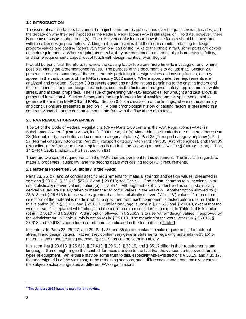
Parts 23, 25, 27, and 29 contain specific requirements for material strength and design values, presented in sections § 23.613, § 25.613, §27.613 and § 29.613; see Table 1. One option, common to all sections, is to use statistically derived values; option (a) in Table 1. Although not explicitly identified as such, statistically derived values are usually taken to mean the “A” or “B” values in the MMPDS. Another option allowed by § 23.613 and § 25.613 is to use values greater than the statistically derived (“A” or “B”) values, if a “premium selection” of the material is made in which a specimen from each component is tested before use; in Table 1, this is option (b) in § 23.613 and § 25.613. Similar language is used in § 27.613 and § 29.613, except that the word “greater” is replaced with “other,” and the term “premium selection” is omitted; in Table 1, this is option (b) in § 27.613 and § 29.613. A third option allowed in § 25.613 is to use “other” design values, if approved by the Administrator; in Table 1, this is option (c) in § 25.613. The meaning of the word “other” in § 25.613, § 27.613 and 29.613 is open for interpretation, as indicated in the footnotes to Table 1.
In contrast to Parts 23, 25, 27, and 29, Parts 33 and 35 do not contain specific requirements for material strength and design values. Rather, they contain very general statements regarding materials (§ 33.15) or materials and manufacturing methods (§ 35.17), as can be seen in Table 2.
It is seen that § 23.613, § 25.613, § 27.613, § 29.613, § 33.15, and § 35.17 differ in their requirements and language. Some might argue that such differences are due to the fact that the various parts cover different types of equipment. While there may be some truth to this, especially vis-à-vis sections § 33.15, and § 35.17, the undersigned is of the view that, in the remaining sections, such differences came about mainly because the subject sections originated at different FAA organizations.
a The January 2012 issue is used for this review. 2
2.2 Special Factors / Casting Factors in the FARs:
The casting factor requirements are imposed in Parts 23, 25, 27, and 29. b Sections § 23.619, § 25.619, § 27.619, and § 23.619, titled “Special Factors,” require that the prescribed factor of safety c be multiplied by the pertinent special factor for each part whose strength is: (a) Uncertain; (b) Likely to deteriorate in service before normal replacement, or; (c) Subject to appreciable variability because of uncertainties in manufacturing processes or inspection methods. The highlighted entry applies to castings.
Table 1: Material Strength Properties & Design Values Requirements Parts 23, 25, 27 and 29
§ 23.613 § 25.613 § 27.613 § 29.613 (a) Statistically derived values.
Meaning “A” or “B” values in MMPDS Reference made to Mil-Handbooks 5,
17, and 23 and ANC-18 (b) Greater values than the statistically derived
values, if a “premium selection” of the material is made in which a specimen from each component is tested before use, to ensure that the strength properties are equal or greater than those used in design.
(b) Design values other than the statistically derived values ** may be used if a selection of the material is made in which a specimen from each component is tested before use, to ensure that the actual strength properties are equal or greater than those used in design.
**Can be interpreted to mean: (a) values greater than the statistically derived ones,
or (b) “S” values. c) Design values other
than the above, * if approved by the Administrator. *Can be interpreted to mean “S” values.
Table 2: Materials in Parts 33 and 35
§ 33.15 Materials § 35.17 Materials & Manufacturing Methods The suitability of materials used in the engine must – (a) Be established on the basis of experience
or tests, and; (b) Conform to approved specifications (such
as industry or military specifications) that ensure their having the strength and other properties assumed in the design data.
(a) The suitability and durability of materials used in the propeller must: (1) Be established on the basis of
experience, tests, or both. (2) Account for environmental conditions
expected in service (b) All materials and manufacturing methods
must conform to specifications acceptable to the Administrator.
(c) The design values of properties of materials must be suitably related to the most adverse properties stated in the material specification for applicable conditions expected in service.
b There are no such requirements in Parts 33 and 35. c A factor of safety of 1.5 is prescribed in sections § 23.303, § 25. 303, § 27.303, and § 29. 303. 3
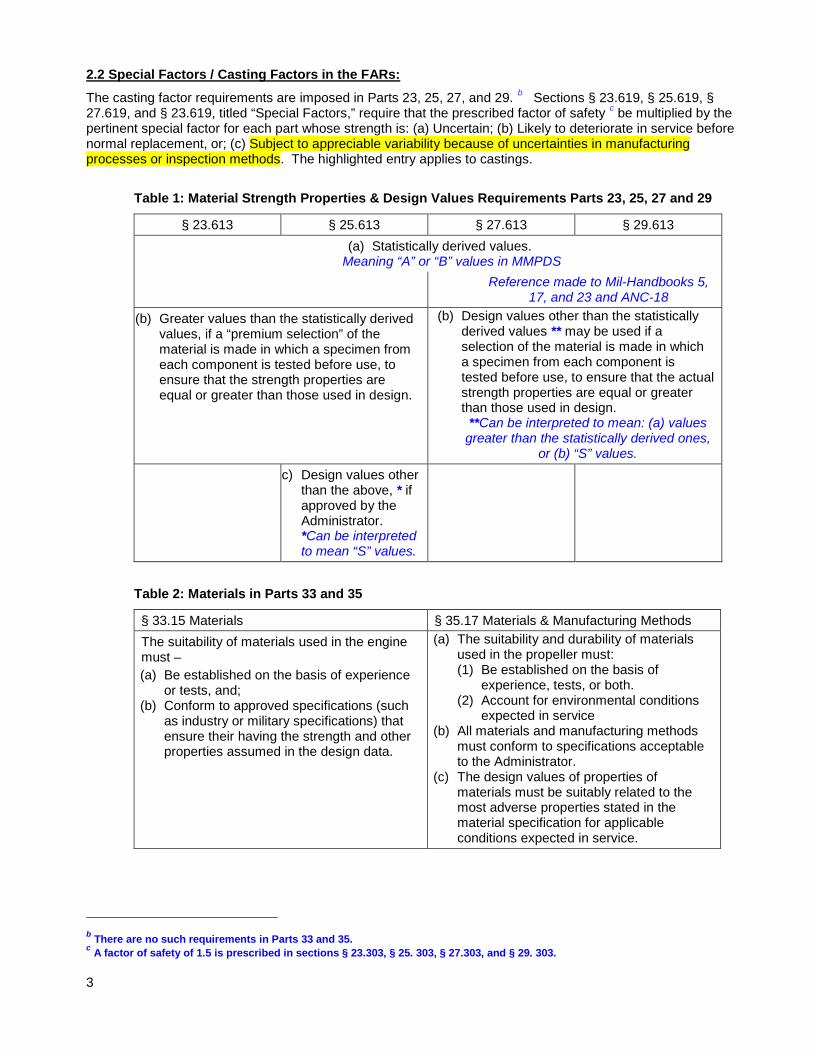
The specific casting factor requirements are listed in sections § 23.621, § 25.621, d § 27.621, and § 29. 621, titled “Casting Factors.” These sections identify two classes of casting, critical and noncritical. In addition to these two classes, section § 23.621 identifies a third class, nonstructural castings. The main casting factor requirements in the aforementioned sections are listed in Table 3, leaving out some confusing exceptions and details that are not essential for purposes of this document; interested parties may wish to consult the FARs for the full text. In examining Table 3, it is seen that the various sections differ somewhat in their requirements and language. As pointed out in 2.1 above, the undersigned is of the view that such differences came about mainly because the subject sections originated at different FAA organizations. This said, the following three observations are in order here.
(a) The FARs impose specific casting factor values / ranges, together with the applicable inspection schemes, based on casting criticality, as defined in the applicable part of the FARs. The applicant (design activity) may choose a casting factor value, together with the specific inspections required for that value, from the casting factor “menu” listed in the applicable section of the FARs. What is being said here is that casting factors are not assigned by the design activity on the basis of the inspection grades or classes called out on the drawing.
(b) No casting factors apply when castings are classified as nonstructural (only in section § 23.621).
(c) The fact that sections § 25.619, § 27.619, and § 29.619 are devoid of the nonstructural casting class implies that such castings have to be treated either as critical or noncritical castings. This means that nonstructural castings are subject to the casting factor requirements and to the attendant inspections, a rather absurd proposition.
Table 3: Casting Factor Requirements in Parts 23, 25, 27 and 29
Class § 23.621 § 25.621 §27.621 §29.621
Critical Casting
1 – Each critical casting must either: (a) Have a CF ≥ 1.25, and receive
100% visual, radiographic, and either magnetic particle or penetrant inspection, or;
(b) Have a CF ≥ 2, and receive 100% approved nondestructive inspection.
1 – Each critical casting must have CF ≥ 1.25, and receive 10% visual, radiographic, and either magnetic particle or penetrant inspection.
2 – In addition, each critical casting with CF < 1.5, three castings must be statically tested to meet certain strength and deformation requirements (spelled out).
Noncritical Castings
1 – Three groups of casting factor are listed, each with its own inspection requirements:
(a) CF ≥ 2, each casting shall receive 100% visual inspection; (b) 1.5 < CF <2, each casting shall receive 100% visual, and either
magnetic particle or penetrant inspection, and ; (c) 1.25 ≤ CF ≤ 1.5, each casting shall receive 100% visual, radiographic
and either magnetic particle or penetrant inspection. 2 – For castings procured to a specification that guarantees the mechanical properties and provides for demonstration of these properties by testing of coupons excised from the casings on a sampling basis:
(a) A casting factor of 1 may be used, and ; (b) The castings shall receive 100% visual, radiographic and either
magnetic particle or penetrant inspection.
Nonstructural Castings
The castings do not require evaluation, testing or close inspection.
*Castings the failure of which would preclude continued safe flight and landing or result in serious injury to occupants
d It is noted here that there is a proposed revision to this section, with a companion Advisory Circular: see Federal Register / vol. 78, No. 41 / Friday March 1, 2013 / Proposed Rules. 4
It has been argued (1) that the CF requirements in FARs are not specific enough, since they only refer to strength without indicating which strength. Accordingly, the argument goes, casting factors should not only be applied to tensile properties, but also to compression, shear, bearing, fatigue, etc. Fortunately, however, casting factor requirements apply only to tensile strength properties.
Worth noting here is that Parts 33 and 35 are devoid of casting factor requirements. e This is a rather fortunate and thoughtful omission for Part 33 turbine engines, which would have incurred a prohibitive weight penalty had it been that casting factors were required for the hundreds, even thousands, of cast blades and vanes used in these engines. As to Part 35, the omission seems to be due to the fact that castings are not ordinarily used in propeller construction.
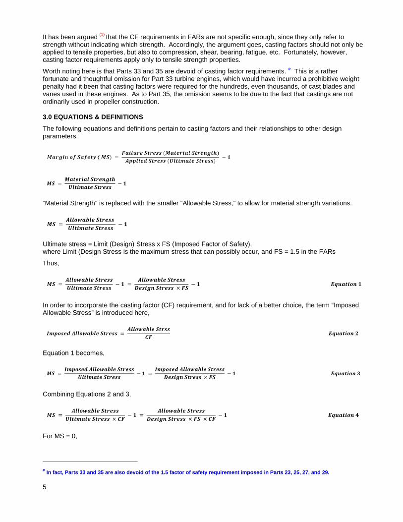
3.0 EQUATIONS & DEFINITIONS
The following equations and definitions pertain to casting factors and their relationships to other design parameters.
“Material Strength” is replaced with the smaller “Allowable Stress,” to allow for material strength variations.
Ultimate stress = Limit (Design) Stress x FS (Imposed Factor of Safety), where Limit (Design Stress is the maximum stress that can possibly occur, and FS = 1.5 in the FARs
Thus,
In order to incorporate the casting factor (CF) requirement, and for lack of a better choice, the term “Imposed Allowable Stress” is introduced here,
Equation 1 becomes,
Combining Equations 2 and 3,
For MS = 0,
e In fact, Parts 33 and 35 are also devoid of the 1.5 factor of safety requirement imposed in Parts 23, 25, 27, and 29. 5
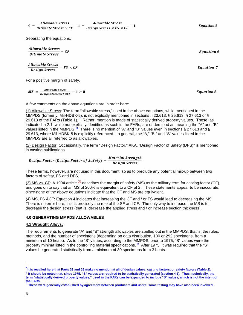
Separating the equations,
For a positive margin of safety,
A few comments on the above equations are in order here:
(1) Allowable Stress: The term “allowable stress,” used in the above equations, while mentioned in the MMPDS (formerly, Mil-HDBK-5), is not explicitly mentioned in sections § 23.613, § 25.613, § 27.613 or § 29.613 of the FARs (Table 1). f Rather, mention is made of statistically derived property values. These, as indicated in 2.1, while not explicitly identified as such in the FARs, are understood as meaning the “A” and “B” values listed in the MMPDS. g There is no mention of “A” and “B” values even in sections § 27.613 and § 29.613, where Mil-HDBK-5 is explicitly referenced. In general, the “A,” “B,” and “S” values listed in the MMPDS are all referred to as allowables.
(2) Design Factor: Occasionally, the term “Design Factor,” AKA, “Design Factor of Safety (DFS)” is mentioned in casting publications.
These terms, however, are not used in this document, so as to preclude any potential mix-up between two factors of safety, FS and DFS.
(3) MS vs. CF: A 1994 article (1) describes the margin of safety (MS) as the military term for casting factor (CF), and goes on to say that an MS of 200% is equivalent to a CF of 2. These statements appear to be inaccurate, since none of the above equations indicate that the CF and MS are equivalent.
(4) MS, FS &CF: Equation 4 indicates that increasing the CF and / or FS would lead to decreasing the MS. There is no error here; this is precisely the role of the SF and CF. The only way to increase the MS is to decrease the design stress (that is, decrease the applied stress and / or increase section thickness).
4.0 GENERATING MMPDS ALLOWABLES
4.1 Wrought Alloys:
The requirements to generate “A” and “B” strength allowables are spelled out in the MMPDS; that is, the rules, methods, and the number of specimens (depending on data distribution, 100 or 292 specimens, from a minimum of 10 heats). As to the “S” values, according to the MMPDS, prior to 1975, “S” values were the property minima listed in the controlling material specifications. h After 1975, it was required that the “S” values be generated statistically from a minimum of 30 specimens from 3 heats.
f It is recalled here that Parts 33 and 35 make no mention at all of design values, casting factors, or safety factors (Table 2). g It should be noted that, since 1975, “S” values are required to be statistically generated (section 4.1). Thus, technically, the term “statistically derived property values,” used in the FARs can be expanded to include “S” values, which is not the intent of the FARs. h These were generally established by agreement between producers and users; some testing may have also been involved. 6
4.2 Cast-Alloys (Castings):
The MMPDS does not explicitly define specific requirements for generating cast alloy allowables. Accordingly, and for lack of a better choice, the same wrought alloy requirements must be used for cast alloys (castings). In wrought alloys, mechanical properties of a given alloy are determined from specimens excised from a given product (bar, plate, extrusion, etc.) of a specific configuration and size. Unlike mill-products, castings that use any given cast alloy come in different designs; that is, come in different configurations and sizes. Furthermore, mechanical properties of castings can be determined from specimens excised from castings or from separately or integrally cast specimens. Thus, generating casting allowables is not a straight forward matter as it is in mill-products. Depending on the type of specimen to be used, there are three approaches that can be used for generating casting allowables.
One approach is to generate the allowables from specimens excised from actual castings, using the same MMPDS procedures for wrought alloys. For any given casting alloy, this requires collecting data from 100-292 castings (depending on data distribution), poured at different foundries from a minimum of 10 heats. By necessity, these castings will have to be experimental (standard) ones of predetermined configurations and sizes. Accordingly, the excised specimens would naturally be of different sizes. One issue with this approach is that generating meaningful statistical data from specimens of different sizes can be problematic. Another, and more important, issue is the fact that actual castings in any given project will generally be different from the standard castings used to generate the allowables. In other words, the generated allowables are not going to apply “as-is” to actual production castings in any given project. This calls into question the value of generating casting alloy allowables. These issues aside, the effort and expense involved in producing hundreds of castings make this approach a rather unattractive one.
Another approach is to generate the allowables from specimens integrally cast with castings. Again, the castings will have to be experimental (standard) ones, as indicated above. This approach, however, makes no sense because the specimens can be directly excised from the castings, without having to go through the extra effort and expense of designing and producing integrally cast specimens.
A third approach is to generate the allowables from cast bars or plates (i.e., from separately cast specimens) having the same size and configuration; no standard castings are required here. This is the most logical and economic approach, and, as such, it is the approach ordinarily used to generate casting allowables. (2) Still, the actual production castings in any given project will generally be different in size from the separately cast specimens used to generate the allowables. In other words, the generated allowables are not going to apply “as-is” to the project castings. This calls into question the value of generating casting alloy allowables.
5.0 CASTINGS-MMPDS VS. FARs
Insofar as casting alloys in the MMPDS are involved, “A” and “B” strength allowables are listed for only three alloys: one magnesium alloy, EV31A, and two aluminum alloys, D357.0 and E357.0; “S” allowables are also listed for the aluminum alloys. The allowables for all the remaining cast alloys are “S” values.
Typically, the MMPDS does not list the type of specimen used to generate any of the allowables, or indicate whether the listed “S” allowables were statistically derived (see 4.1) or they simply represent the property minima listed in the casting material specification. An exception to these generalizations is aluminum alloy E357.0, for which the MMPDS indicates that all minimum design values listed are based on testing investment cast plates; i.e., all “A,” “B,” and “S” values are based on testing separately cast specimens. It also turns out that the “S” values listed in the MMPDS for this alloy are the property minima listed in the casting material specification (AMS 4288); both listed under “non-designated area.” The same holds true for cast aluminum alloy D357 (AMS 4241A).
A cursory review indicates that, for cast Inconel 718 (AMS 5383), cast aluminum alloys procured to Mil-A-21180, and other alloys, the “S” values listed in the MMPDS are also specification minima. Unfortunately, however, not all the cast materials specifications referenced in the MMPDS were available for a detailed review. It is important to note here that Mil-A-21180, now inactive, required that production lot acceptance be based on testing of specimens excised from castings
Based on the above, it is safe to assume that the “A” and “B” allowables listed in the MMPDS are based on testing separately cast specimens, (2) and that, in general, the listed “S” allowables reflect the property minima listed in the casting material specification.
7
Inasmuch as the FARs are involved, sections § 23.613, § 25.613, § 27.613, and § 29.613, indicate, in general terms, the type of design data that can be used, without explicitly mentioning “A,” “B,” or “S” values, or the type of specimen used to generate those data. Furthermore, sections § 23.621, § 25.621, § 27.621, and § 29.621 impose casting factors regardless of the type of design data involved or the type of specimen used to generate those data. Casting factors also apply even where casting lot acceptance is based on testing of specimens excised from castings (Mil-A-21180). The conclusion to be made here is that casting factors apply regardless of whether the design data used are statistically derived or otherwise, and regardless of the type of specimen used to generate said design data or for lot acceptance testing.
6.0 DISCUSSION
The chronological casting factor history, presented in the Appendix, strongly suggests that casting factors find their roots in the use of separately cast test specimens for casting acceptance testing. The need for such factors comes about because separately cast specimens solidify differently than casting sections, and, as such, they are likely to exhibit different properties; the same holds true for integrally cast specimens. Further support to this history-based view comes from a 2009 research report (2) which proposed that one reason for the continued use of casting factors is utilizing statistics to derive design allowables (the “A” and “B” strength values in the MMPDS). i The report explains that the design allowables approach is an attempt to control cast part reliability and vendor quality, based on separately cast test specimens. What is being said, in effect, is that using statistically derived design values (allowables) in design analysis mandates the use of casting factors, since these allowables are generated from separately cast specimens.
While the use of separately cast specimens stands out as the root cause for the adoption and continued use of casting factors, other causes have been proposed over the years, notably, (a) casting anomalies, (b) variability, and (c) the inability of foundries to achieve reproducible properties.
(a) Casting Anomalies: In 1955, a Lockheed manager argued that casting factors are necessary to “cover casting anomalies,” such as porosity and foreign inclusions. (3) This argument seems to be proposing that a specific casting factor value would be imposed at the design stage to cover casting anomalies whose nature, extent and intensity can only become known after actual castings have been produced. Who is to say that the anomalies would not be such that a larger, or smaller, casting factor value should have been used? And how can anyone speak of casting anomalies without distinguishing between castings, integrally cast specimens and separately cast specimens? Clearly, the argument advanced in said reference (3) is unreasonable.
(b) Variability: There was the case described by Douglas in a 1961 paper (4) where a specific casting was made at two foundries, one of which consistently produced castings with at least twice the tensile strength of the same castings produced at the other foundry. The paper argued that this variability is the reason behind the continued use of casting factors; in fact, as indicated in 2.2, the FARs themselves impose casting factors because of casting property variability. This argument requires further analysis. The usual means to account for foundry to foundry variability is to generate statistically derived, “A,” “B”, or even “S”- type properties (allowables), utilizing data obtained from multiple foundries and multiple heats; the larger the number of foundries and heats included, the more representative the generated allowables would be. These allowables, however, are usually generated from separately cast test bars, (2) and, as such, they are likely to be different from their counterparts determined from specimens excised from castings. Accordingly, a casting factor is imposed to account for the use of separately cast specimens, not to account for foundry to foundry variations as stated in the FARs and proposed by said paper. (4)
(c) Inability of Foundries to Achieve Reproducible Properties: The1961 Douglas paper (4) argued that casting factors would be unnecessary if foundries used the proper procedures. Along the same lines, the 2009 research report (2) argued that one reason for the continued use of casting factors is the inability of foundries to achieve reproducible properties, due to the lack of technical predictive tools (modeling, FEA, simulation, etc.), many of which became available only recently. This argument requires further analysis. Certainly, foundries would be in a better position to achieve reproducible properties by utilizing the available predictive tools to intelligently design castings, and then by adhering to the best practices and procedures in production. No matter how reproducible properties might be, separately (or integrally) cast specimens will still solidify differently than casting sections and, as such, they are likely to exhibit different properties. This being so, casting factors would still be required if separately or integrally cast specimens are used to
i The report actually proposed two reasons for the continued use of casting factors. The other reason is discussed in (c) below. 8
generate the data employed in design analysis. Thus, the arguments advanced in the paper (4) and the report (2) are thought to be invalid.
The fact that the continued use of casting factors is variedly attributed to a multitude of reasons is evidence of the confusion that shrouds casting factors and the casting allowables issues. Another evidence for such confusion is manifested by the contradictory views expressed in two of the cited references. (1),(2) Specifically, the 2009 research report (2) proposed that one reason for the continued use of casting factors is the use of statistics to derive design allowables. Arguing the exact opposite, the 1994 publication, (1) stated that using statistically derived design allowables would obviate the need for casting factors. The undersigned is of the view that this latter argument is invalid, since design allowables are generated from separately cast test specimens, (2) and, as such, these allowables are likely to be different from their counterparts determined from specimens excised from castings.
A note on statistically derived design values (allowables) is in order here. By now, it should be clear that these allowables are generated from separately cast test specimens. As such, their use in design analysis does not obviate the need for casting factors. This seems to call into question the value of allowables in casting design. The undersigned is of the view that the derivation of such casting allowables should cease, and that castings be altogether removed from the MMPDS. This is especially so in view of the tendency of some design activities to consider the existence of such allowables to be an alibi not to impose the necessary qualification and lot acceptance testing on production castings. The undersigned of the further view that the casting factors and materials properties / design values (allowables) requirements be removed from the airframe parts of the FARs (Parts 23, 25, 27, and 29). Support to this view comes from the fact that Part 33 (Aircraft Engines) of the FARs is devoid of such requirements. This is so in spite of the extensive use of cast polycrystalline, directionally solidified (DS), and single crystal (SX) cast alloys in turbine engine component applications, such as blades and vanes. That the use of castings in such applications has been a resounding success seems to be testimony that casting factors are unnecessary. A better choice for Parts 23, 25, 27, and 29 is to require testing of specimens excised from castings, at least on a lot basis.
7.0 SUMMARY / CONCLUSIONS
7.1 Casting factors find their roots in the use of separately cast test specimens for casting acceptance testing. Other views expressed in the literature are thought to be invalid.
7.2 The FARs impose specific casting factor values / ranges, together with the applicable inspection schemes, based on casting criticality, as defined in the applicable part of the FARs. Casting factors are not assigned by the design activity on the basis of the inspection grades or classes called out on the drawing.
7.3 Casting factors apply regardless of whether the design data used are statistically derived or otherwise, and regardless of the type of specimen used to generate said design data or for lot acceptance testing.
7.4 The undersigned is of the view that the derivation of casting alloy allowables should cease, and that castings be altogether removed from the MMPDS. This is especially so in view of the tendency of some design activities to consider the existence of such allowables to be an alibi not to impose the necessary qualification and lot acceptance testing on production castings.
7.5 The undersigned of the further view that the casting factors and materials properties / design values (allowables) requirements be removed from the airframe parts of the FARs (Parts 23, 25, 27, and 29). Support to this view comes from the fact that Part 33 (Aircraft Engines) of the FARs is devoid of such requirements. This is so in spite of the extensive use of cast polycrystalline, directionally solidified (DS), and single crystal (SX) cast alloys in turbine engine component applications, such as blades and vanes. That the use of castings in such applications has been a resounding success seems to be testimony that casting factors are unnecessary. A better choice for Parts 23, 25, 27, and 29 is to require testing of specimens excised from castings, at least on a lot basis, to verify conformance to drawing / specification requirements.
Terry Khaled, Ph.D. CSTA, Metallurgy Federal Aviation Administration (562) 627-5267 [email protected] 9
References:
(1) Dale McLellan, “Understanding Casting Factors in Aircraft Components,” Modern Casting, 1 October 1994. (2) FAA Report “Design and Quality Assurance of Premium Quality Aerospace Castings-Part 2: Integrated Design Approach for the Boeing 757 EE Access Door, Appendix A, “Historical Evolution of the Casting Factor and Related Foundry Methods,” August 2009. Not officially published; no report # assigned. E-copy is available upon request. (3) Papen, G.W., “Castings in Airframe Design,” AFS Transactions, vol. 63 (1955), p. 425. Quoted in reference 2. (4) Bailey, W.A., and E.N. Bossing, “High Strength Aluminum Alloy Airframe Casting,” AFS Transactions, vol. 69 (1961), p. 494. Quoted in reference 2.
10
APPENDIX
HISTORY OF CASTING FACTORS
A review of the literature reveals that casting factors are older than commonly thought. The following is a chronological list of the history of casting factors. While the list is fairly extensive, it may not be all-inclusive.
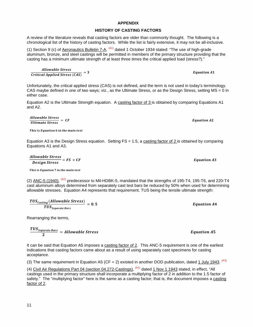
(1) Section 9 (c) of Aeronautics Bulletin 7-A, (A1) dated 1 October 1934 stated: “The use of high-grade aluminum, bronze, and steel castings will be permitted in members of the primary structure providing that the casting has a minimum ultimate strength of at least three times the critical applied load (stress?).”
Unfortunately, the critical applied stress (CAS) is not defined, and the term is not used in today’s terminology. CAS maybe defined in one of two ways; viz., as the Ultimate Stress, or as the Design Stress, setting MS = 0 in either case.
Equation A2 is the Ultimate Strength equation. A casting factor of 3 is obtained by comparing Equations A1 and A2.
Equation A3 is the Design Stress equation. Setting FS = 1.5, a casting factor of 2 is obtained by comparing Equations A1 and A3.
(2) ANC-5 (1940), (A2) predecessor to Mil-HDBK-5, mandated that the strengths of 195-T4, 195-T6, and 220-T4 cast aluminum alloys determined from separately cast test bars be reduced by 50% when used for determining allowable stresses. Equation A4 represents that requirement, TUS being the tensile ultimate strength:
Rearranging the terms,
It can be said that Equation A5 imposes a casting factor of 2. This ANC-5 requirement is one of the earliest indications that casting factors came about as a result of using separately cast specimens for casting acceptance.
(3) The same requirement in Equation A5 (CF = 2) existed in another DOD publication, dated 1 July 1943. (A3)
(4) Civil Air Regulations Part 04 (section 04.272-Castings), (A1) dated 1 Nov 1 1943 stated, in effect, “All castings used in the primary structure shall incorporate a multiplying factor of 2 in addition to the 1.5 factor of safety.” The “multiplying factor” here is the same as a casting factor; that is, the document imposes a casting factor of 2.
11
(5) Civil Air Regulations Part 04(a), dated 9 November 1945 (A1) imposes a “variability factor” in section 04.31100. A variability factor of 2 is required when the castings are only visually inspected. Other variability factors, including 1.25, may be used, depending on the inspection methods. The imposed variability factors are the same as casting factors.
(6) The trail of casting factor history then leads to QQ-A-601. This is one of the oldest specifications used for procuring aluminum sand castings, and it was used extensively in the aerospace industry. Beginning with Revision A, dated 3 February 1950, the specification included a statement identical or similar to the following: “Unless otherwise specified, the average ultimate tensile strength and average elongation of test specimens cut from castings in accordance with section 4 shall be not less than 75 percent (to the nearest ksi [5 MPA]), and 25 percent (to the nearest 0.5 percent) respectively, of the values specified herein for separately cast test bars;” see Note A1. This statement translates to the following equations, with “TUS” being the tensile ultimate strength, “e” the tensile elongation, “Excised” meaning specimens excised from castings, and “Separate” meaning separately cast bars:
Rearranging the terms of Equation A6,
Equation A8 describes a casting factor of 1.33. This lends support to the notion that casting factors came about as a result of using separately cast specimens for casting acceptance; see item (2) above. A Northrop paper (A4) has recognized the influence of QQ-A-601 on casting factors.
Note A1: The statement, however, did not always appear under the same paragraph number. Revision A: para. 3.8.3 (c). Revisions B (3 September 1957) and C (14 September 1961): para. 3.4.3.1. Revision D (28 April 1967): para. 3.3.3.1. Revisions E (15 April 1974) & F (23 March 1981): para. 3.3.2.1. Revision F was the last revision before the specification was cancelled on 23 January 1991. The same statement appears in other specifications; e.g., ASTM b 26.
(7) Civil Air Regulations Part 4(b), dated 31 December 1953 [section 4(b).307(a)-Casting Factors] (A1) required that “Each Casting, the failure of which would preclude continued safe flight and landing of the airplane or would result in serious injury to the occupants shall have a casting factor of at least 1.25.” For other structural castings, the regulation defines four (4) casting factor groups; specifically, 1.00-1.25; 1.25-1.50; 1.50-2.00, and; > 2.
(8) To this day, the casting factor requirements, imposed by the above government documents remain, in one form or another, in the FARs and in the design guides of aerospace companies dealing with civil aircraft.
(9) In the late 1950s, Douglas, (A5) and Grumman (A6) designers noted that “experience has shown that actual strengths of most aircraft castings correspond to about 75% of the strengths of separately cast test bars.” To account for this strength reduction, those designers indicated that “design loads have to be multiplied by a factor of 1.25-1.5 for castings. This is in line with QQ-A-601 (item 6 above) and the Civil Air Regulations requirements (item 7 above).
(10) Mil-A-21180, released in 1958, and similar aerospace company specifications written in the early 1960s, required that the tensile properties of castings be confirmed by testing specimens excised from castings. This, according to the above referenced Northrop paper, (A4) obviated the need for casting factors. Unfortunately, the paper adds, the “bad” reputation of castings had already been established, and, accordingly, designers still required casting factors for most structural casting applications. The paper, however, points out that there were exceptions: thousands of Northrop’s F-5 and T-38 and General Dynamic’s F-16 castings with no casting factors were successfully designed and built; the “secret” was tensile testing of specimens excised from castings. In a subsequent Boeing paper, (A7) the same author points out that cast-on coupons (integrally cast specimens) solidify differently than casting sections; see Note A2. As a result, casting acceptance should be
(Average) (Average)
(Average) (Average)
12
based on testing of castings or specimens excised from castings, not on cast-on coupons; integrally cast coupons are good only for heat treatment verification.
Note A2: Integrally cast coupons or prolongations are attached to the castings; separately cast specimens are not.
Appendix References:
(A1) An untitled and undated FAA Presentation. E-copies are available upon request. The documents referenced in that presentation could not be found on-line, and, as such, they could not be reviewed for independent content verification.
(A2) ANC-5, “Strength of Aircraft Elements,” issued by the Army-Navy-Civil Committee on Aircraft Requirements, Revised Edition-October 1940). A copy may be ordered ($ 20) from eFlightManuals.com
(A3) “X-Ray Inspection of Castings (Army Air Forces’ Requirements),” dated 1 July 1943, Robert Katz, University of Nebraska-Lincoln. Published in Metal Progress, Volume 44, No. 1 (July 1943), pp. 89–94. E-copy is available upon request.
(A4) “Structural Aluminum Aircraft Castings with no Casting Factor,” John Gruner, M&P Casting Specialist, Northrop Grumman, 22 April 1996. E-copy is available upon request.
(A5) Carah, A. J., “A Case Study of a Premium Strength Casting of 220-T4 Aluminum Alloy,” AFS Transactions, vol. 63 (1955), p. 703. Quoted in reference A8.
(A6) Mead, A. R., “How Aircraft Designers Look at Light Metal Castings,” AFS Transactions, vol. 67 (1959), p. 457. Quoted in reference A8.
(A7) “Aluminum Castings-Strength Determining Factors,” John Gruner, Sr. Engineering Specialist, Boeing, Information, Space & Defense Systems-Reusable Space Systems, 5 February 1998. E-copy is available upon request.
(A8) FAA Report “Design and Quality Assurance of Premium Quality Aerospace Castings-Part 2: Integrated Design Approach for the Boeing 757 EE Access Door, Appendix A, “Historical Evolution of the Casting Factor and Related Foundry Methods,” August 2009. Not officially published; no report # assigned. E-copy is available upon request.
13