Embed Size (px)
Citation preview

REPORT 1091
EFFECT OF ASPECT RATIO ON THE LOW-SPEED li4TERAL COINTROL CHARACTERISTICS OFUNTAPERED LOW-ASPECT-RATIO WINGS EQUIPPED WITH FLAP AND WITH
RETRACTABLE AILERONS ‘
ByJACK FISCHEG RODCEFt L. NAESETH, JOEIX R. HM-IEBMAN, and ~ILLIAM M. O’HHtE
—.,
SUIW$IARY
.4 [ow-spwd un”nd-tunnd investigation was made to detirmine
the lateral control eharacteri&~ of a 8eries of untapered lowa~p~ct-ratioVX%W Sealed I@ aikrorw of rariou.9&pensandspanwi$e [ocatiww were inreatigatedon unwept wing$ of a8pmt
mtim 1.13, 2.19, J.13, and 6.1$?; and rdriml~projeetiong ofO.b’&enaiqan retm.ctableai]erong uxre inrrstigated on the un-wept u<nggoj aqwt mtiw 1.1S, 2.13, and ~JS and on a @
sweptback wing. The retractable ailerons inre~tigated on the
unswept winge 8panned the outboard 8tat&m8 of each wing;
frherea8 the plain and stepp[d retractabk aikrom in restigated
on the Weptback wing were locatedat mriaw gpanu.i.se8tatiom.‘1’lMmriation qf experimental Jap aileron e~eciirenese with
wing a~p~ct mtio was not accurately predicted for all qx-m8 ofJap ai[eron8 by any one of th~ three theoretical method8 with
which a comparison UW8 made. Flap aileron e~ectirene8s in-
creased as aileron 8pan or wing aspect miio uxw incremed.
The rolling e#ectirene88 of 0.50-sanipan outboard jfap ailerona
decr&a8ed with incream-ng a8pect mtio, eazept for the low lift-
me.ficient range, where the a8pect-ra4io-S.19 wing gare 8omewhat
h ightr M.&La of rolling ej%tirene88 than the a8pect-ratio-l .1S
lning produced.
At equa[ aileron projections, the rolling eJectir&e88 of the
retmctable ai[eron8 increased with increase in a8pect ratio ofthe unwrept winge and decreased with wing 8tceepback; how
<r@r, the rolling celocitie8 of the wing8 te8ted are e8timated to be
appro.rirnately equal for a. giren wing area at the man-mum
uikron projection inre8tigated.
The aileron effe-ctirene88 of plain mtractab[e aikro-n8 on the
suwptbark wing g( nera[[y ~ncrea8ed when 8pa nwi8e [oca.tion of
the aileron UX8 mored inboard; #ha’&a8, the eJectirene88 of.#~pped retractable ailerons on the 8ame wing generally in-
c’rea~ed at 10w and moderate ang[e~ of attack when this span-
vi~e location wa~ rnored outboard.
ktign charti ba8ed on experimental result8 are prewnted fortxtitnatittg th~ &p aileron eJectire~88 for louwpect-ratio, un -
t(zpered,unswept whgs.
INTRODUCTION
Ixm--aspect-ratio wings are being incorporated in currenthigh-speed aircraft and missile designs because their use de-la~-s the onset of or reduces adverse compressibility effects(reference 1). One of the problems encountered in such
designs is the provision of adequate Iateral control Theh’ationd Advisory Committee for Aeronautics is currentIyinvestigating the applicability of various types of lateral-control devices to wings having plan forms suitahIe forilight. at high-subsonic or transonic speeds. In addition toflap ailerons, a promising Iateral+ontrol device, the retract-able aiIeron or spoiler, is being investigated. Previous spoiler-aiIeron in-rest igations made with unswept and swept wingsof moderate and high aspect ratio (references 2 to 8 and un-”published data) indicate some of the beneficial effects thatare obtained with spoiIer aiIerons, such as: increase in rolhngmoment with increase in Mach number, increase in rolling ef-fect~reness with increase in Lift-flap defection, generally fa-vorab~e yawing moments, practicable use of ftdl+pan flaps-with spoiler ailerons, and smaIIer viing twisting moments thanflap aiIerons and hence higher re-rersd speeds with spoileraiIerons (reference 9). in addition, spoiIer ailerons providelow stick forces; and, in the investigation of reference 3, noappreciable effects on the hinge-moment characteristics viereobserved with chmges in Mach number for the spoiler aiIeron.
A series of untapered Iow-aspec&ratio vringa was investi-gated at low speed to determine the effect of aspect &Ltio on
-the IateraI control characteristics of the wings. Four un-swept wings (aspect rktios 1.13, 2.13, 4.13, and 6.13} wereequipped with 0.25<hord seaIed flap ailerons of variousspans and spanwise Iocations. Three of the same W&-S(aspect ratios 1.13, 2.13, and 4.13) were tested with 0.60-semispan spoiIer ailerons of the retmctable type at the O.iO-
wing-chord station and, in addition, an unt.apmed 45” swept-back wing of aspect ratio 2.09 was tested with 0.60+emispanpIain and steppwi retractable ailerons at- the 0.70-wing<hordstation. The effeets of retractable-a.iIeron spanwise Iocationand deron actuating arms on the lateral control charac-t&istics of the sweptback wing were also determined for boththe plain- and stepped-retracttdkaileron configurations.
The Iateral control characterist ica as vieIl as basic aerody-namic characteristic and Iateral-stabiIity paramet era of thewings are presented. .
COEFFICIENTS AND SYMBOLS
The data are pferred to the stabiIity axesz (fig. 1), whichare a system of a~es with the origin at the center of moments(O-25 M.LC’. (M. 2 to 4)). The Zaxis is in the dane of.
!SUpWXASSNACA ‘rN 2347,“EM of Asp?etBstIoand Swe@ack on the Low%xwi Ukrfd Crmtroi Ckactdst.—
b of mltsperedLow-Aepect-Flstio mngs Equipped WftilFLetrWableAiIerons” by XI@ Fkhel SM John B. Hk.mrmmj1%1, sml h-ACA TN =4S, “EITect of &pect Bath m ths Iaw-Spsed I#dersl Control CbsrmerMCnt.spmd Low.Asp?ct-IlntioWbqs” by Rodger L. Nnesethsad WfflfamM. O’Hare,1951.
ks of unswe@
.649

650 REPORT 1091—NATIONAL ADVISORY COMMiTTEE FOR AERONAUTICS
symmetry and pe.rpeml icular to the relative wind, the Xaxieis in the plane of symmetry and perpendicular to the Z-axis,and th~ Y-axis is perpendicular to the plane of symmetry.
The coeflicie.nts and symbok used are defined as follows:c. lift coei%cient (Lift/qS’)CL) d~g ~~~fi~ie~t (I)lag/@)
c, lateral-force coefhcient (Y/qS’)c. pitching-moment coe.flicient (Ik@S’FJc, rolIing-moment coficient (L@’fJ)c, yawing-moment cocfficien~ (N/qSb)y IatwaI force, poundsAl pitching moment about I’-@s, foot-poundsL rolling moment due. to control about -X-asis, foot-
poundsN yawing moment due to control about Z-axis,
foot-pounds
—.-—
J.,
. .
//’
Lift
T
i--+----- I
o! --”---4=EZ5L+~4-J..__—..—-------- —.. — ...
N\----
Refoilw wind
Y“<
2
sgciion A-A .
Flourm L-system of ahbfllty axes. Podtha vahtesof fore%%momenq and angleaarelndkate+iby WIKIW&
s“ wing area (table 1), squaro feet
$! free-atrettm dynamic pressure, pounds pcr square
()%foot g P
A .- aspcct ratio (table 1) (bA/S)
P mass densitty of air, slugs per cubic footc 10I24J1wing chord, measured parallel to plane of
symmetry, feet75 wing mean aerodynamic chord (table 1), feet
-- (:1’’2”4c~ 10CRIa~eron chord, feetC,p damping-in-roll cocffwient, that is, rate of change
of rolling-moment coefficient with wiug-tip
helix angle(“%$)
pb/2J7” wing-tip Mix aJ@e, radiansb“ wing span, measured para]kd to Y-ti.xis (table 1],
b.
,1/
I/o
yi
A8=
feetaileron span, measured parallel to Y-axisj feetlateral distance from plane of symmetry, meas-
ured parallel to Y-axis, feetlateral distance from” plane of symmetry to out-
board end of ail~ronj measured paralleI to Y-axia, feet
lateral distance from pIane of symmetry to iu-board end of aileron; measured parallel to Y-axis, feet ‘
roMng veIocity, rhdia.ns pm secondfree-stream velocity, feet pcr secondangIc of attack of wing-chord plane, degreesangIe of yaw (angle betwmn reIat.iv~ wh’wl and
plane of symmetry), measured in S“Y-plane,degrees
angle of sweeplmck, degrcmaileron deflection relative to wing-chord plane,
measured in a plane perpendicular ta aikmnhinge axis and positive when t~iling cdgo isdown, deuecs
,“
c,/Aa rolling-momant coefficient produced by 10 ditTer-ence in angle of attack of various right and leftparts of a complete wing
* flap-effectiveness parameter, L*t is, effectivechange in \@ng angle of attack caused by unitangular change in control-surface deflection
(L/D)ml maximum ratio of lift ta drag
TABLE I.—GEOMETRIC CHARACTERISTICS OFUNTAPERED LOW-ASPECT-RATIO WING MODEM
“NACA 64AOI0ahfollwt[ou normalto the winglexltns add
...i ..As&” SW&l
D$4a&@fr&n
‘gEoo&tcord M$jC. Al%a
@q fq‘m*@
&19 o“ &lW 1.fall tlm7418 0 :. ?%
azwh021 @.@z’ .300
9.IS o 8.m 1.714 &ma ; g;20s3 X448 2.469 6.2.94
i: 4! s.Ss5 L72.2 1.n8 a L54 1.27!3I 1 I 1 , 1 I —

EFFECT OF ASPECT.R4TI0 ON THE LATERAL CO~OL CHARACTEFtISTICS OF LOVT-ASPECT-R.4TI0 VTL?JGS 651 .,. _
acfL)~%=(-&- g=.()measured near a=O”
‘“U()
Cja = ~ measured near &= 0°a
● a-o
Subscript:max maxinlum
.4 any aspect ratio unless due of A is given m in
@i)* =6I-Ming-moment and yawing-moment coefficients represent
the aerodpamic- moments on a eomp~et e wing produced bydeflection of the flap aileron or projection of the retractableaileron on onIy the right semispan of the wing.
MODEL AND APPARATUS
Each complete-wing model was mounted horizontally ona single strut support in the Langley 300 MPH 7-by 10-foot
,
tunnel, and all forces and moments acting on the model wersmeasured by means of the tunnel btdance system.
. ..—.-.—. . ..—
The geometric characteristics of the unt&~ered complet;-~wing models investigated are itemized in tabIe I, arid-”_..-.sketches of the mode19 are gbren in figures 2, to 4. The wingmodels had A7ACA 64AO1O airfoil sections, and the -&g tipswere formed by rotating the airfoil sections to produce”’ ‘jbodies of rwrolution. The models were constructed of alaminated mahogany arid stee~ core enclosed in a cove&
.—-..._
composed of %-inch sheet aluminum glued bet~~-ee~ sheets.. _
of %-inch fir.—.
, —
PIain ailerons were investigated on the unswept wings of ,-aspect ratios 6.13, 4.13, 2.13, and 1.13. The right kemispfi .—of each -wing was equipped with a 0.25c aluminum flapdivided into four parts. The deflection of each flap segmentwas adjusted by means of hinge cIan~ps. The hinge-linegap and aII c.hordwise gaps between flap segments of equaldeflection were sealed for all tests. Because the wings of -aspect ratios 6.13 and 4.13 were thin, bodies of revolution- —(fig. 2) -ivere used as fairings to encIose tie strut pi~ot and ““thereby totare effects.
,
< b=61C@
(4
permit more accurate determ”matiori of strut ““
.
It
[1“
!c =/. 732
L
LWr23* ‘. -- .--, --~
“2373+ – --- ‘-==p— -g
<— b = 5%37f@— ...
I
(8) A-RI*(b] A-4.13.
I ,-—
.-
-—
FmuE.E%-oeometrk rhamcterfstiMof theunsweptuntaperei whigsinvestigated.wuh5p ailerons. All dime-. am in feet.

652 REPORT 109 l—NATIONAL ADVISORY COtiITiBIl FOR”AERONAUTICS
Rettwctable ailerons were investigated on the unsweptwings of aspect ratios 4.13, 2.13, 1.13 and on a 45° swept-back wing of aspect ratio 2.09. One of the two configura-tions of retractable ailerons investigated consistwl of plain,
0.60$ continuous-span, retractable ailerons attached to the
upper surface of tlhc right wing along the O.70c line of eachwing model (figs. 3 and 4). TLto other ccmtiguration coti-sisted of si.. individual retracM.de-aiIeron segments, each
having a span of 0.10$ and a total aileron span of 0.60 :J
aLta&d to the upper surface of Lbe right wing of the 45°sweptback-wing model in a stopped fashion with the span ofeach segment normal to W plane of symmet’ry (fig. 4). Themidpoint of each stepped-ret ractable-aileron segment wason the O.70c line of the sweptback wing, Several ailerons,each having different projections, were used in tests of thetwo retractable-aileron configurations, and each aileron wasprefabricated of aluminum angle and was mounted in sucha manner that the front face of each aiIeron wa9 normal to
/
J I
T....
.611 ~ ~
&-f- , ...$
I
~~~ ‘ l“”
ilI 2.448 i
0.70C-4—
J
i...-4‘AJe’rot%
,orojecti~
P248 * ““”- ““”’(c) t- b-za~ -. .... . . -. .. ... . .. .
(P.)A-4.13.:;; <:4;.
. .
.%–GeemetiIo cbaractertWagof the unswept untapwed wtngeInvostlgakd withrrtmetablea!hxons. (All dimetions are!n feetexmptwhereded.)
the wing surface (figs. 3 and 4). On tho unswepl-wingmodels, the ailerons were mounted ou the ouLbuard portionsof the wing; whereas, on th(! 45° swepthtick-wing modvi, hospanwise Iocation of. the aikmns wa9 varied during Lhcinvestigation. To distinguish clearly between the twoaileron configurations investigated on the swcptback wing,they are referr%d to herein as Lhc “pl~in retractable aileron”and the’(stepped retractable aileron. ” The body-of-revtdutionfairing (fig. 2) was not &cd on the A=4.13 wing for theretractable-aikon tests (fig. 3).
—.
F=’’”-+ “II
I
}———— ‘b%3.586 -].-
“1. \
‘ A’“.-I @,.8#9 ‘t
“:l_A. ‘
It ““ -3.464 - , ~1 “.-L.-
FIWBI 4—.GwmeCrIcohwscterlstlcaof the 4b0sweptbi+ekuritriperwlwtrrginwat&etMwith plainend$teppti retnic4abIerdlerone. A -2.0!3. (All dimerxtiome.roIn feetexo?ptwherenoted,)
EFFECT OF ASPECT RATIO ON THE LATEFML CON’TROL CHARACTEIWSTD2S OF LO’iV-ASP~CT-RA’ITO WINGS . 653
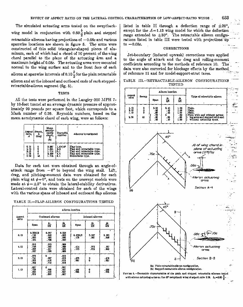
The simulated actuating arms tested on the sweptba.ck-
wing model in conjunction m“th 0.60 ~ plain and stepped
retractable aiIerona having projections of —0.08c and variousspanwi.se Iocations are shown in figure 5. The” arms wereconstructed of thin solid triangular-shaped pieces of alu-minum, each of which had a chord of 10 percent of the wingchord paralleI to the phme of the actuating iirm and arna.ximum height of 0.08c. The actuating arms were mountednormal to the wing surface and to the front. face of each
aiIeron at spamvis.e intervaIs of 0.10 ~ for the plain retrac.tabie
aileron and at the inboard and outboard ends of each stepped-retractabkaileron segment (fig. 5).
TESTS
Ml the tests were performed in the Langley,300 JIPH 7-by lo-foot tunnel at. an average dynamic pressure of approx~imately 99 pounds per square foot., which corresponds to alIach number of 0.26. Re-ynokls numbers, based on themean aerodynamic chord of each wing, were as follows:
r
.
Data for each test were obtained through an ang&of-attack range from –6° to beyond the wing stall. Lift,drag, and pitching-moment data were obtained for eachplain wing at- #= 0°, and tests on the unswept modds were
made at ~= +5° to obtain the Iateral-stabihty deri~atives.Lateral-control data were obtained for with of the wingswith the various spans of inboard and outboard flap atiemna
TABLE 11.—FL~P-AILERON CONFIGURATIONS TE9TED
~“
Fill”‘‘‘~.016 .0i3
&u .716 .243 :: .414 .m .s7
@ “:E .ss9 ‘m.Oia .!4!3
1 ;% o .s7s213 .ni .IKs .4i6
.mz.476
.43 .ST8 .237 :.ZY .7-IS .93
.m
.% o .%7. .
L13 .m .P5i.s3s :%.275 .CsZ :g ~ = ~ :%
. .
listed in table 11 through a deflection range of >200, =e..cept for the A= 1.13 wing model for which the ddkction .._range intended to +30°. The retractable aiIeron configu- ‘“-‘“______..:rat ions listed in tab~e HI were tested with projections upto —0.08c. —.—
CORRECTIONS
Jet-bounda~ (igducd upvrash) corrections were appIiedto the angle of attack and the drag and rding-mornmtcoefficients according to the methods of reference 10. The ‘“-data were also corrected for. Mockage effects by the method - ‘of reference 11 and for model-support-strut tares.
.-:-..=_—. —. —
TABLE IH.—RETR~CT~BLE-.AILER0N COXFIGUR.lTIOXSTESTED
AuerorIImtfonAemmtio Smep Tfi ofrehactghle aileron
m= $ &-.
. . . .“ .7413 0 am ha 1.111 ;% .-z13 0 -m .40 LmL13 o ;g .40 I.m m:
{o
Zw 4s~h with and without .wtmst.
.EQ .m %
.60 .$0 L Cu ) %Kg’a’.~gu~’~L ------
“’.A?e?mnWchwthq
[a)secrliln A-A
_ -’..c.
-- ..-.
,.:=.<
—
,-t
—,-
- -—
. . ..-
Aii “ ,- .=...—.-.—-=-..
Secfin B-B
(a) PMn-retr?dable@eron eonSguratlon.(b) Stepped+etmctable.tieron eon8gr@fon.
FLGIXS5.-Ueornetdc chametwistfeeC/ the PMII and etep@ retrac+abIedlarons testrdwith aflemnnctustingarmeon the@ aweptba.ck=hwof EW?C4Win 2.09. 6.-CI.KI $.
-:-.-.
,.. .
—.
,--

654 REPORT 109 l—NATIONAL ADVISORY COMMIfiEE FOR AERONAUTICS
DISCUSSION
WING AERODYNAMIC CHARACTERISTICS
Effect of aspect ratio, —Lift, dr& and pitching-momentcharacteristiee of tho wing modds are presented in figure 6.The variation of C~d, C~~~t, (L/n) ~.z, and. aerodynamic-center location with wing aspect ratio is shown in figure 7.
Tho data of f~ure 6 show fairIy regular variations ofa, CD, and C. with CL except for the A= 1.13 wing. Thelift curve of the A= 1.13 wing exhibittid a break botwccna= 16° and 18°, and a corresponding rapid drag rise and a[arge change in pitching-moment co&cient toward morenegative va.Ium occurred in this a range. Observation ofthe ~ufts on this wing showed that this phcnpmenon occurredas a result of a sudden leading-edge separation which leftonly the tufts in tho region of the wing tips definitely steady.lVith decrease in the angle of attack, observation of the tuftsindicated that the flow reattached at about the Sarnc valueof a and over an equally small increment of a. This phenom-enon may be a function of the Rqmolds nurnbor of thotests and may not exist at flight Reynolds numbers.
The wing lift-curve slopes increased with increasing aspectratio (fig. 7) ~d the variation of CL= with aspc~t r&tio wasaccurately predicted by the method of reference 12. . Thevariation of maximum lif~ coefficient and (L/D) fia. withaspect ratio is similar to that reported in referenco 13 inwhich an investigation of Iow-aspcc&ratio wings of Clark Yairfoil section indicatad a peak wdue of the maximum liftcoefficient at about A= 1 and an increase in (W) ~~. withincreasing aspect ratio. The aerodynamic center of eachwing model, measured at low Iift coefficients, vras ahead ofits respective quarter chord of the mean aerodynamic chord.This distance was small for the A=2.13, 4,13, and 6.13wing models but became significant for the A= 1.13 wingmodd. AS indicated in figure 0, above CL*0.5 all of t.hcpitching-moment curves became stabIc.
4 compmison of the. unswept wing. ofEffect of sweep,—.mpr.ct ratio 2.13 with the 45° swcp tbtick wing of aspect ratio2.O!Iindicates that the maximum lift coefficient of the swept-bti.ck wing was larger than that of the unswept wing. Theaerodynamic-center locations for the two wings were atabout the same percent M..4.C. Sweeping the wing backhad little effcct on the value of (~~~)~.=.
A theoretical vaIuo of C’L=of 0.042 computed for the sweptwing by tho method of refcrencc 12 agrees very weIl with themperimental lift-curve slope (meamred uear CL= O”) of 0.041.
LATERALSTARILITYCHARA13’EIUSTTCSOF UNSWEPT WINGS
The variation of tho lahmd-stability derivatives Cl,,C,$, and CY+ with lift coefficient obtained for the unsweptmodeIs is given in figure 8. The effective dihedral parameterL’~+increased appro.xirnately linearly with increasing CLuntil the wing began tO stall,Since the extent of the. lift-coefficient range wherein et ~Varies hea.r]y with CL is a f~c-tion of Reynolds number (unpublished data), the experi-mental dab are not necessa~y indicative of the variation ofCl~ with CL near & \v& stall for fright Reynolds number.
The slopes Of the CWVCS of C;* plothd ~wains!J CLmeasured near CL= O increased with decreasing mpcct ratiO;this variation of Cl* with CL for various aspect ratios agreesqualitatively with the variation reported in refcrcncc 14.
Throughout the Ii&cocfficient range, thu wducs of Ca~and CF~. were small. The values of C% wm gencrulIyslightly negative and the negative vidues iudicatz posit ivodirectional stability.
LATERALCONTROL CHARA(7ERE3TIC3OF FLAPAILERONS
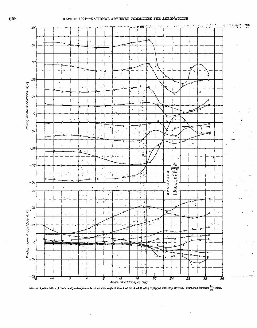
‘.RolIing-momenkocfficient and yati”g-momont-coofllcientdata obtained through the angh+of-attack range for MAof th four wings equipped “with various spans of out-board and inboard flap ailerons are premntcd in figures 9 to 32.Crosi plots of Cl against 3. at a= O“ for the aileron spanstested on the unswept wings arc givtm in. figure 33. Theslopm of k curves of Cl against 8’ for outboard aiIcrons,measured at 6.=0° in figuro 33, are presented in figure 34
Rolling-moment characteristics.-Thc data for the A= 1.13”wing (il.gs, 9 to 14) indicate a rapid loss in aileron cffcctivc-.ncas at an angle of”attack considcraliy Mow the plain-wingstall but approximately tho same as or slightIy above thatangle at which tho leading-edge separation previously dc-scribcd occurred. BCIOW ~his angIe thu curves of rolli~~g
“moment against, anglo of attwk indicate ,fairly constantrolling moments for d deflections.
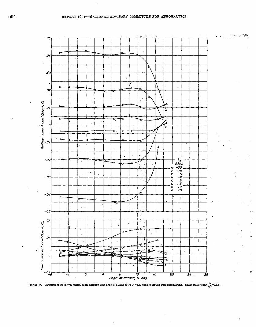
The curves of rolling momenh againsL angIc of attack forthe A=2,13 wing (figs. 15 to 20) show rclativcIy constantrolling moments over the angle-of-attack range up to L.hoangle of attack for plain-wing sttdl.
The data for the A=4.13 and 6,13 wings (figs, 21 to 32)indicate generally constau t rolling moments up to tlw angleof attack for pIain-wing stall for negative aihxon deflections.The rdiing moments produced by positive deflections, how-ever, ten&d to approach zero at a lower nnglo of attack as the .ailw%n dc”ilcc~ion was increased. This efftwt ww more pro-‘nouncecl for the Iarger+pan ailerons.
Iu general, thu A= 1.13 wing gavo fairly constant rollingmoment& over an increased angle+f-attack range for greateraileron deflcctious th-m did the higher-aspcc t-ratio wings.
The curve of Cl,plotted against 6. at a= 0° for tho A= 6.13wing sho& a decrease in effectiveness at abouL 8.= 15°;wherea9 the curvw of Cl pIottcd against ad for the wings ofIower aspect ratio have generally constant slopes throughthe deflection ranges tested (for A=4.13 and 2.13, fit= +20°;for A=l.13, 8.= +30”). (Sco fig. 33#)
The spanwise-cflcwtivenoss curves of the ailcrone on thofour wings (fig. 34) show that aileron eflectivencss decreasesas aileron span or wing aspcc t ratio decreases. However,because the damping in roll also decreases with decreasingaspect ratio (refcrencc 15), tho ratio of control-aurfacc areato wing area required to maintain a constant rolling dlcc-tiveness will not show so great a variation with decreasingiispcct ratio as indicahxl by tlw aileron-cffwtivcness data.

.
TO WINGS.’
5 .,.. _.=IF ASPECT RATIO Oh’ THE LATERAL CONTROL CHARACPERB~W OF LOW-ASPE~-RATEFFECT O
.,*.~:“---
-. ..-..-
~“—... -.,-=%,-:-.
-:-
-
.,. - .--,,-... ~ ._.->...=..-
.“=.—-~--a. .~
, .: ..—
-K-:.-.-----
. .
.e -.- -..------ ---
-. - ,.- —._.—. .
-—-r.-
-_& .>
.-
..—-----
-4
I t
I t I v 1A 1 r,
A VI .
I I. B .8 /.0
.,
A- A w n 1II
-8+I I.4 72 u z .4_— .-
.,.
.-..

656 REPORT 1091—NATIONALADVISORYCOMMITTEEFOR AERONAUTICS
‘I=#ImlJ2
1I
...,8
, ,.9
=.*a.
6
.08
.06
.04
cL&
.02
0 r 2 3 4 5 6 7hspec.t raiiq A
FIGURE7,-Vnriation of CL., C~.ti (I@).=, snd aertiynamio.mnterIomtionwith aspecttatlofor unsweptwhws.
The rolling-moment data of figures 33 and 34 show thatspam+m+ffectiveness curves based on the effectiveness ofoutboard aik+rone can bu used to estimate the @octhwmssof iuboard ailerons (reference 16) because the value of Cla for
an aileron spanning any portion of the wing is the diller&cebetween the wdues of Cl, at the inboard end and C~,~at
s
. . . ... . ..=
.
—.
, -- .-
the outboard end of tho aileron. The clFcctivmxe of theidward ailerons estimated in this mannm agrees reasonablyMl with the, corresponding v~ucs of C;~ determined from
figure 33. A comparison of thu valuo of Cl, for inboard and
outboard ailerons (fig. 33 or 34) sho~m that ~utboard deronaare more effective than inboard ailerons of the smnc span.

EFFECT OF ASPECT ILiTIO OX THE LATERAL. CONTROL CEAR4~_RISTICS OF LOTV-ASPECT-RATIO WLiiGS 657. ...._ _..91
Cyp o
:0I
.002
c’% “o.
7m2
.008
.004
%-
.002
0
+70~8 .4 -2 o. .2 .4 .8 .8 LO
Lift cueffidenf, CL
—
.
—.
---
—
-T, —
FIGUMs.–VOMIOU d the dt!riwhks CW C.t, @ Cr+ with Ilft meffiden: for the mwem w@3.
.
{i5S REPORT 1091—NATIONAL ADVISORY COMMtlTEE FOR AERONAUTICS
b.‘Utboti ‘]C- F7ir””gn”
.:. -

EFFECT OF ASPECT RATIO ON T13X LATER4L CONTROL CHARA CTERL9TICS OF LOIV-ASPECT-R.4TI0 WINGS 659
.. . ...A.r
----... —.=-..-i=-... ---‘ .- —_+
.+._._.,,,. —....<
*
---- i.=--- —-.-.. . .-.. .. -=.=
___::”.-+. .:—
..-—
.--.
-- —...-,-—.,:-. . -
,. .:.,. .—
-“-..“. ..-
-- -T;..
.&-
...-.-.-.:...
~.-
,“’. ..
.---—.----
.-

‘REPORT 109I—NATIONAL ADVISORYCOtifiEE FOR AERONAUTICS
,
-T
,.

EFFECT OF ASPECT IUTIO ON THE LATEKRAL CO.N’FROL CHAFt.4CZERISTICS OF LOTf-ASPE@-Rk’lTO ‘WINGS
Fuimx 12.–VortatIon of the Metal mntrol chumeterktlcawith oogIeof attsck of the.4 -1-U wingequipp?d with ilnp dlerons. Outbmrd alkroq $=0275. “-.
661.- .-+--
—. .-..<... -,
-:..5
--— .-”. .-.
. . .
.>-:-
“.-.:..
.. .....-:
)...-_
-,.—.:=
.,.r——
Yawing-moment characteristics .-The total yawing-nmment coefficient rssulting from equaI up and down de-flections of the ailerms was approximately zero at smallang[es of attack but became adverse (sigg of yaw-@ momentopposite to sigu of roMng moment) as a was increased andas the aiIeron deflection was inmeased.
Th~ negative yahws of the (2J(21 ratio for each wing didnot exceed —0.2 for lift coefficients equal to or k than
0.9 C’L=*Z,except for the A=l .13 wing for which a sharprise in – C~C; is judged to refieet the abnormdy highvah.ws of drag above ~~= 0.55 previously discussed. Forthe range of aspect ratio inwstignted, it appears that theproblems associatwi tith adrerse yavrhg moments on un-swept wings of moderate aspect ratio I.xeorne serious weIl -,below CL~=Zif partiaI flow separation in the Iinear Iift range
is characteristic of the wings.

‘%K)
Yayq–moment coe fficfeyfi C..1 RoJli~g-momenf coefficient+, Cz.,
Illw
I 1 II II I
I II,.tT-”n.,..,*.. I:.;;,,
l-: .,I,):
I 1::

.
I 1 1 1 4-M !! I 1 1 I I 1I I I If fftl
o
I I I I I ‘“
Ill Iwlbl 1 I I I I
& — — —
*
8 ‘
(w
●
FIGUB8
REPORT 109 l—NATIONAL ADVISORY COMMITTEE FOR AERONAUTICS
-. .. —.
*“-...> ---
,-
,
.-
.-
16.—VarMkmof the latad contioIcharacterktk%with ende of attackof the.4-2X3 wfrMequippedwith Eepetlkrons. Outbmrdailerons;*-O.97K

EFFECT:OF~ASPE4YT RATIO ON THE LATERAL CONTROL CHARAC17ERJSTICS OF LOW-M3PECT=WTI0 W17SGS (w--—
FIcmI 16.—Varlationof the herd controldmmcterlsticswith ongieof attackot the .4-!iJ3 WLUeqaip~ with I@ sfkmus. Outbmrd Weronq ~.iil.
- -——

REPORT 1091—NkTIONAL ADVISORYCOMMITTEEFOR AERONAUTICS666
.-.L-. ,-*
—
,
-L- . :—
,..
.T
. ..
. . ..
. .
. .
FIGURE17.—Vc.rfatlrmof tbEHerd controlcharaet.det!cawith ringleof .%ttackof theA -Z~ wInEequippedwith flapaUerons. Outbcdirdtirons”‘%
-0.302.

EFFECT OF ASPECTRATIO ON THE LATEXL4LCO-NTROLCE.ARACTERLSTICSOF LOW-ASPECT-RATIOWINGS 667:
.
... —. . ...
.,, -+- -—
.-- .-=
...a---—-—-:*--—
-—=. ..—
---:—.>-—. . . .—- .-+;
.-e.
—-
. ..=..—
.i
-—..—.
.. .
FIGFMlK-Vsriat!4n 04he Iateml cmtd ebaiacterlstimwltb mgle of attack of the A-MS wfng eqnlpped WM flap allmn8. Outbmd aileronq g-am%.-
..
,

REPORT 1091—NATIONALADV160RYcO*ltE FOR iU3RONAUTICS
.4ng@ of otimk, &, deg
Fmmm 19.—VmIationof the lateral control ohe.ruc~rlstlmwlb angle of ntt~kofthe.4-2.13wfngeqrrlpmwiWIUIflap sflrrons. Inbmrd aflerons;$-O.47G
Angle of attack, U, &g
.:*. ,- ..
.
.-
-L . . . ---., -----
: .“”.a....;:.s..,
..
—
FIWREW.-Vrarfr4kmd the lateralcontrolehamoterfstfcswith M@ of attack of the A-2.13 wfrrgequlpfrd with flap atierorrs. Inbmrd allcrmnq~=o.n?.

EFFECT OF-ASPECT IL4TI0 ON TEE LATERAL CONTROL CE41Ll~RISTK%3 OF LOT-ASPECT-RATIO WINGS 669 ._
.
-. h
. . L -2.- 02
-m -— — — — — ~ — — — — — — — - 5: 10L 20 “b
-.08 ,
.02
b=T
&
$/ — \
1’ Ab
Anqb of attack, U, &q
!21.–Ved?.tkmoftheMend cmtd chamderistlca with sngk of attack of the .4-US WIIWemIPped with @p ailerons. Ontbwd alkmm;
. ..
...—
.- —.:_.. .—
;~=.:m
..-=—. .._
.+ .““..L..—:..
...- .-
. .. .—- .,=-
.&. .. —-.- _-
----
. ,_—-.. .
-—_—-
“----“* .. .
.L -
. . . . . . . -
. ,—
.“G,;..-. ..-.------.--
. .
-. --

670 REPORT 1091—NATIONA.L ADVISORY COMMIT’IZE FOR AERONAUTICS
.—.
.,
-a
-.0!; 1 I 1 I 1 1 I 1 1 t I~ ~
-4 0 4 R )> 16 90 9A.- --~ngle of ot%ck, ~ cfe~
.-.
Wion of the 18temlcontrolebaractarktkswith angleof attack d tbe A .4.13 wing er@pped wl~ @ Merons. Outboardailerons;
.: .._..: ..:-
&a74a.

.
EFFECT OF ASPECT’ RATIO ON THE I.ATERAL CONTROL CE4RMH’ERL9TICS OF LO’W-ASPECKHL4TI0 VTINGS 671
-.
.-:.---~,..
.-r.—.. ...
.-..-:
-* .
* “-
.,
—
FI,;URI
Angle of of tack, ~ deg
:Z3.-VarWIon d the Isteralcontroidmctelmti Rfih angled atlxk of the A-M3 * eqn!ppel with flap ULIerom.Outixmni&llercmq$#Oz

●
REPORT 1091—NATIONALADVISORYCOMMI~E FOR AERONAUTICS
-.
. !35..02
i.”. o to
G*. .
,$$
0 .u t
-F
g
*.-$ . .
-,0/-8 -4 0 4 8 i2’”” /6 20 24 28
-.
.Arr@ of otfock, a, ~
lWwRE24.—VariEthrof the 18terdmntiol jharwcterlethewiChonjje of attackof the A-418 w~g cqulppedwith tl8Pallarons.
—
. .
. ..-
.-
.
. .-
.-
,
----
—

Yaw,%g-moment Rolling-moment
Coefftitifl c, coefficient, C’,
G
23’
I-+-++- pO”” ~
Yawing -nmmenfcoefftiknfi Cm Rohg-momenfcoef ficient, Cl
F-+-+--H t- P o Q o tl---+-+-+---
.’
1,
0%1

REPOBT 1091—NATIONALADVISORYCOMMITTEEFOR AERONAUTICS
Amgfe of attack, a, *
--
.
.
Fmurm%’.-arieit!ononof the Satmd crmtruloharaoterlstkswith @e of sttsck of thoA- tl.lawingeqolppcd !rlth flapailerons. Outbaerdailcrons;~0.W!l.bfl

EFFECT’ OF ASPECT RATTO ON THE LATERAL CONTROIJ C!HARACTERLSTICS OF LOW-ASPECT-RATIO WINGS 675, -._
.081
1 I
-
-4 0 4 8 12 16 m 24 iAngk of of fock, U, &g
--.—. —“—. .L“.—
.“ -. :
-.~
.=--.--
-=... .- -
----
..-
- =..—..“=
.—
-.,
.-L-e
..”.-
. .
.-.—L--
..—.-
FIGt?M 28.-T”artafIon of the Iateral wntrd characterlstfcawith aiuI? of ati?.ckof the .4-6.1S wtng equlppeclwith 5P afkrons. Outbcmrdailcron$ *.746.

REPORT 109 l—NATIONAL ADVISORY COMMITI’EE FOR AERONAUTICS
,
t 1 $
.
I I_(24 .
v .0 -200 -lb
t b-.04
r /
b n 4“ i:- w-: -
-5-— L -2
0 25.
d : 10. A 20
-.06 I I I I I !-
1 I I,.. .:. ...,“, .
.02 TG T . .::-.. ;.g..# t i i ii i i i L-k--H T“i ii i IIr,.
FTTFFR:I
& I I I I
4+1 I I I’1 I.y
—y +\
$I:..
-.01-8 -4 0 4 8 12 .16 .20 24 28
Angle of at fock, a, cfeg
,
, -.......+ -,r-
-.
.-
,..,=..-.,..
-...4 . .
-. ... +
+>“ -.-
. . . . . ~“, .-Y
...-,. .. :2;,?:..-. ,
.,.
FIGUMEzv.-%krhucmof the lateral mntrol characterietkew-IfJIUMCof attack of the -4-8.13 *g HIUIPWd wMh @ tilmrm Outhmd amro~; &o.6oll

EFFECT OF ASPECT RATIO ON THE LATERAL CONTROL CHAR4CTERE3TICS OF ~W-ASPEC’T-R4TI0 WINGS 677 —
..
.

678
FMWRE
FIQUBE
El
REPORT 1091—N.4TIONAL ADVISORY COMMITTEE FOR AERONAUTICS
,.—
.02
F b“
#{&g)
-.02n -10
.Ofo&z
~ ~e
IJo + m * + + * & ~ & + & E g
l??
$2
-.oj -8 -4 0 4 8 /2 16 20 24 28
An91@ of affak, a, deg
NL-Vsrletlm of the Maul mntml ehamcterletlmwfth ahgleof attack of the A-6.lS wing equipped with tip aflerme. Iuboerd allwom,%-o”’*”

EFFECT OF ASPECT RATIO ON TB33 LATER.kL COLNTRO~ CHARACTERISTICS OF LOW-ASPECT-R-4TI0 WINGS 679 . .. .--
Ci
-.
-.
-.
.
l+t--H-4?[ o
.02
Iii iii, , r , , , I I ,
I I I I I IIi 1 I 1 I
-W+H+H++Iii iii
I I , 1 , r 1 1 1 1t
- A I I I I I } I I 1“1
Y.\I \h
Iiiiiiii iii J \
I I I I I I 1 } ‘?I (c) ! k I - (d)I
%’0 -20 -10 0 /0 20 30-30 -20 -10 0 “ 10 20 30
w .4-Lm.(C)A-4.X3. 8 fi%fk
.
FIGUEE39.-VariMon of roUing-mouwnt oxffkld with fb dkon dd.ecU~ for varfom aIkMI ~ u=@.

w.) REPORT 1091—NATIONAL ADVISORY COtiIfiE FOR AtiRONA~ICS
Fwuu 34.-AUeroo eflectlvaness ~mel.w C~=. as ~ outboard flap athron& Thesymbols do not repreeent&t pdnti but arerw?dfor ennvenlenoi!n plottku the .Ma.
LATERALCONTROL CHARACTERISTICSOF RETRACTABLEMLERONS FORUNSWEPT WINGS
The rolling-moment and yawing-momemt charactcristiceover the angk-of-attack range of each of the unswep Lwing
bmod els equipped with 0.60 – outboard retractable ailerons
2at various projections me praented in figures 35 to 37.Chose plots of the rolling-momeut data of figures 35 to 37plotted as a function of retr~ctublc-aileron projection andwing aspect ratio are presented in flgurcs 38 and 39,respectively.
Effect of aiIeron projection.—The Values of C; producedby projection of the retractable aiIerons on the unsweptwings of aspect ratios 4.13 ‘and 2.13 generally decreased withincrease in angIe of attack up to the stall angIe; however,the values of Cl produced by projection of the MractaldeaiIwons on the umnvep t wing of aspect r@io 1.13 variccl er-ratically with change iu angle of attack and became com-pletely reversed for vmious projections above angIes ofattack of 18° to 24° (fi@. 35 to 37). This angIe-crf-attackmnge of aileron reversal for the wing of aspect titio 1.13corresponds to the range of sepamted flow over the pIainwing, where a pttrtial flow rceovcry probably is caused by
tho tip vortex on the wing rearward of the aikron. (Seefig. 6.)
Each of the unswept wiugs exhibited a region of zero orreversed aileron tiectivenma for small aileron projections,and the uileron-pmjcction range for this phenomenon de-rrcascd with increase in wing aspect ratio (figs. 35 to 38). Athuger aileron projections, the variation of Cl with retrac.tablch~lilerou projection -was generally fairly Iinear for each oftbe wir~ (fig. 38). Beoauso the data of references 3 and 4
indim”te that an increase in aileron effcctivcncss wdh increasein Mach number may bo ~xpticted over tic entire projectionrange for this aileron configuration, particuhuly for smallaileron projections, t& uforemcntioncd ineffoct.ivc region ofrd foi”smal] ailero]! projcctiona is believed to be materiallyalleviated in flight at high-subsonic sped, For the wU”of aspect ratio 1.13, it is rathr dubious tht this ineffectiveregion of roll would be completely eIimiuaLcd by increases inMach number, but on the other -wings, rolling-mommteoefEcient would probabIy lw more linear with retractable-ailercm projection. Other means of alleviating & ineflec-tivcnc%s ‘of the rctractdIc aileron at small projections arc alsoavdable-such as slotting the wing immediately behind theaiIeron and thereby making it a plug Awon (refcrencc 5).
The. yawing moments produced by projection of th} rc-tractahle ailerons on the Lhrec unswept wings wwc gencrrdlyfavorable (having the same sign M the rcd]hlg moments) and .increa$ed IinearIy except at small projections with increasein aiIeron projection (figs. 35 to 37). The values of C,decreased with increase in a on the wings of aspect ratios 4.13and “2.13 but increased with increase in a up to a= 200 on thewing of aspect ratio 1.13.
Effect of wing aspect ratio. —l?or n givenaileronprojection,
largerdues of Cl vrcre prqc?ucwl as t.ho wing aspect ratioincreased. This increase in C’lwith incream in a$pcct ratiopa larger at low lift coefficients and was almost linear (fig.39, also figs, 35 to 38]. &o, as discussed in tho prcccdingsection, increase in wing aspect ratio of the unswepL Wing’sreduced the nileron-projection range of zero or rewmcdaileron.eff ectiveneas encountered at small projccLions (figs. 35to38). ~
At small values of a or C’.L,more favor-able values of C*wero produced by given aileron projections as tho wing aspwtratio was increased, but at Iarge vahMs of a or CL, an Oppmitoeikt oc~cd (figs. 35 to 37). In addition, tlm ratio of C’=to Cl tended to decrease with increase in wing aspect ratio,particdar]y at h~e v&]um Of ~ or CL.
LATEEALCONTROL CHARACTERISTICSOF RETRACTAME M~~R~N~ Fog...@ SWEPTBACK WING
The ding-moment aud yawing-moment characteristicsover the angbof-attack range of tho 45° swep Lbtick wing of
baspect ratio 2.09 equipped with O.GO- plfiin and stepped
2b b
retractable ailerons located from 0.20 ~ tu 0.80 ~ and having
various projections are prc~cntcd in figures 40 and 41. Therolhng-moment datu of figur& 40 and 41 are shown cross-plothd against aileron projection in figure 42. The cffccta ofaileron spanwise-lcmatiouand of dcron actuating arms on hIatwal control characteristics of tlm swcptback wing equipped
bwith 0.60. - plain and stepped retractable ailerons hav-
2.ing a projection of –0.08c are shown in figures 43 and 44,respectively.

EFFECT OF ASPECT IMTIO ON THE LATFJL4L CONTROL CHARACTERISTICS OF LOTV-ASF%CT-~TIO WINGS 6s1
,,
..-—--2D
v -40?A
m--’
-60d -8.0
*
LI
t
A+ of attock, ~ o%g
‘s.datfan d lamal omud chometeriet!cswitheagleof attsck of the unsweptontaperd wing o! ass ratfo4% eqofpped with retzactabk M
.
.—
. .----. ---....———.,
.—.—
enuu. bs-0.#~ -

682 REPORT 1091—NATIONAL ADVISORY COMMITTEE FOR AERONAUTICS
d
++H-+
A-..-
A17eron profictibn
~ercent cM)i“ -0.5
z -1.0A -2.0
“v -4.0
-4 0 4 8 i2. 16 20 24 28
-.. .
1
Angk of of fock, ~ deg
FIfiuRE36.-V8rlatiOnof.18t.amlecentrolckameterIst.Ieswith arwle of attack of the tma~eptuntapcn?dwingof aspeetratio 2.18eqnfpped with retructablcafl-. b.-0.00 +.
-. —.
.-
FmuEx87.—Variationof lateral eonhvl chare.ctabth with angle of attack of the unswept unt8LHrd wbagof aspectratio 1.13equlPLM with mtrnctabIeaiIerons. b.-O.M $.
,,I ‘,”

6s4 REK)RT 109 l-—NATIONAL ADVISORY COMMI~.E FOR .4ERONAUTICS
6
.04I t
Aileron projection(oer.enf chord) . /<
.— — -z : “,.03 I
.,/
.
.(2? /. .
.. . ./ . .
/ : d. “.——.
:/’ :.
ts.or / /’. > “ ●
,,=.
~
, ::
/ ,“/“ .-
/,.
? (a) / ~
u,. . . . .. .
to..
;u ,o,# —..——. . , ,.
$ ) “, .’‘,& . .. :c,<3* ,03 -.. .
.;
.
.02 /. . . ..,..
. ,..,; */
/ #~...:.;.. , >
.0/, ,.- --
0-./
— —. /’
b) /“/
. . ‘-,
0 i *2 3 4 5Aspect rdio, A
$] %::”,. .khuME ~g.-Efl@ of wfng MIHA rat!o on the mlllng-moment chfkrectarIetIceof the unswept
untaperedwlngnequipped w’fth retractableaiWronn, b.-0.60}
Effect of aileronprojection.-Thcvaluesof Cl produced byvarious projections of Lhc. plain and stepped retractableaihmms varied nordinearly ovwr the angle-of-attack rangeand, with the exception of a raugc of small proj ectiona, variedalmost linearly with uiIeron projection (@s. 40 to 42) i Theregion of aileron incffectiveuc~s or reversed effoctivencss,which occurred to a slight extent as noted in figure 42 forsmall projections for the plain retractable aileron, was alsoobserved on the unswept wings but, as previously discussed,was found to be a low-speed phenomenon and should bealleviated at high-subsonic speeds (references 3 and 4).. This[Mert of Mach number would thus bc expected to providefor an almost Iiuear vmiatiou of Cl with dcron projectionRt high+uhsouic speeds, a phenomenon whicl~ has bwm notedin some unpublished data d tained on another myep tback-wiug model at high-subsonic speeds.
Tiw yawing moments produced by projection of both plain
and smppwl retractable aiIerons wrr(’ genmdfy favortihl{! a~valu~ of a below 18° and lxwamo ICSS fnvmdic with afurther inc.reasc in a (figs. 40 and 41). WWh both rctractahlc-aikron confignrationa, C. increased almost linearly withaileron proj cction txcept at smalI projections.
Cornpi&on of plain and stepped retractable ailerons,—Comp&cm of the clatw of figures 40 and 41 shows that the
0.60 ~ p~ retractable tiilcron located from 0.20 ~ to 0.80 ~
gener~lly proc?uccd larger values of ~’ at small vtducs of a “”and sma]I!v values of Cl at large vahies of a thtit~ tlw steppudretractable aileron located at the same spmmiec stations.Both ailerons had some effcc.tivtinws near t.hc wing stalIangle. At small aileron projcctious, Lhu plain r[’tract.d)h:
. aiIero; *gRn-eriIly exl;ibite{{ zero or rcvmstd cflcctivcnmsjvih6rc~s the stcpp(d retrac tablti Aron always had positiveeffcctivcncss.
Thq plain retractable aileron gwwrally produc(;d hug[~r -”
(more. favorable) values of C. at various project.iom thaII did‘tie st+pped retractalk aiImon over the w@-of-attark rcmge.
Eff~ct, of aileron spanwise location, —Tho values of rolling-bmomc~t cOcfficieriLproduced by a 0.60- plain rrtrart.able2.
aileron” projected —0.08c gc;icrally immmscd apprccinbly asthe “ai@jn was moved inbotird on the wing (fig. .43), This ,trend ,Wreqs with unpublished results obtainwl at low speedfor a 51°”swcpthwk wing of aspect ratio 3.1. Tho values ofCJ pr&Iiccd by steppoci rctractublc ailmous gcmmdly in-crcasql @ Iow and moderate angles of ath(:k when theai.le.ro~, ~yere”moved outboard on the wing (fig. 44). Thh “.trend at low and moderate values of a is opposite to LIMLnoted ~ti-in ifivcs;iation of u 42° swophrk wing of USI)UCtratio ~4.01 (refcrcnco 6) and in the invcstigmlion of llwaforerne’itioned ~i 0 swcp Lback wing of aspect ra ~io 3.1.
V&n the ailerons were moved outboard on tlw wing,howeieij the vahws of Cl produced by stepped rotrartalhailerons decreased at very large angles of at.ttick. Thistrend is in agreement with the data ob taimxl OH tho otherwings at very Iarge vaIuc5’of cr. Reasons for this discrepancy
are unkmowi but it may be attributed b“ differcurus ili }iinggeometry-pmticularly, in tlhc wing asprct ratio.
In gencmd, the inbourd, O.GO~/plnin rctraclabh’ uihron,
which was the optimum configuration for the plain rAra&able aileron on the 45° swept buck wing, produced hwgcrvalues of Cl over the angle-of-attd range of the wing mo~lelthan did the optimum configuration for the stqqwd rctroct-abIe aikwon, which was the outboard stupp(d rctruehdh
aileron. ._With eithr t.ho pI~in- m stepllt!d-rctru(: tabIc-aileml] con-
figur~.tion, C’, generally decreased (Ixcame less favorabh!) os
the” 0.60~ aileron was moved inboard on th wing, but C. was
genergl& Iargcr for all plain retractable ailerons thau forcomparal)] c stepptij retr~c.table ailerons. This dccrcasc fi”C, as the aiIeron movtxj inhow-d Rgrcm with results obt+linedon the aforementioned 42° and 510 swcptbark wings (rrfur-encc 6 and unpunished data, respcctiveIy),

EFFEC1’OF ASPECT IWTIO .ON THE IATERAL CONTROLCHARA~~CS OF LOTV-.4SPE~-R4TIO WDKX36s5
.-------
“—..I
4--~ -
—-..——.
- . . -—.----
._..-. .,
1 1 1 1.-. [11[ I I I I -- 4.
.L~L=
_-
.:..:=<_=. -- .-.- ——.:..—-- .+...—.-:.++
_ .r . . ..—
;“...—
.Angle af attack, a, a@g
.
.-
---.—
.-<.-. .-u
-.
.“.. --
..-. ..-.-----
----- ..-....
. .
F14;1W4L-
.

REPORT 1091—I?ATTONAL ADVISORY COMMIY’I’EE FOR AERONAtiIC9
t3-
F
.02
,01
0
-.0/
.02
.0/
0
-.01-8 -7 -6 -3 -2 -/ i?
~ %on proj~f;~, pWcet7f chord
‘~b;;tf%+~~k%%i;? s
‘iauwa4Z..-Varfathmof mllhwmoment memdent with retractsbk+alkmnProlwltonon“the46° sweptb~k untmemd wIm of fmmctredo 209. b.- O.fM;; UI-U.~ ~,b h“
. .. . . ... .-=

EFFECT OF ASPECT ILLTIO ON THE IATERAL CONTROL CHARA CTERISTICS OF LOW-ASPECT-RATIO VTINGS
.01
0
t II
dim
-.02
.03
.02
.OI —
o </
-01-8 -4 0 4 8 r2 - 16 2U 24 2&
.4nqhs of attack, c+ deq
6S7
.-
*

688 REPORT 1091—NATIONAL ADVISORY COldliITT’EE FOR AERONA@ICS
Effect of aileron actuating 4trms,-The addition of aileron
actuating arms (fig. 5) to 0.60~ plain and stepped retractable
ailerons having a projection of —0.08c at each of threespanwise Iocations generaIIy tended to increase the va.hwaof C’1produced by the ailerons aIone over most of th~ tmgle-of-atttack range, exceptat smallangl&sofattackforthe plain
retractableaileronat the two inboardlocationsinvestigated
(figs.43 and 44). In general,the effectson d,produced by
the actuatingarms were very smallat low anglesof attack,
exceph with the stepped a.ikronaat th~ inboard location,
but were appreciableat largeangleaofattack.
With thu ~~ceptionof tho outboard stepped retractable
aileroninthelow angle-of-attackrange,au aileronconfigura-
tionsexhibitedshghtlylessfavorableyawing-moment char-
acteristicswith aikon actuatingarms on the wing than
When the aileronsWere testedalone on the wings (figs.43
and 44).
Effeotofwing sweep,—A comparisonof thedata obtained
bwith outboard, 0.602 retractable ailerons on the unswept
wing of aspect ratio 2.13 (figs. 36 and 38) with comparable
data obtained with miclsemispan, 0.60~ plain and stepped
retractable ailerons on the 45° sweptback wing of aspectratio 2.09 (figs. 40 to 42) shows that the aiIerons on bothwings generally produced a linear variation of Cl with uiIeron
projection ovor most of tie aileron-projccLicm rangp. Atgiven values of lift coefficient, thu retractable ailerons onthe unswept wing generaIIy were tipprcciallIy more efhctivethan on t,ha swep tback wing; however, because tho wingstall occurred at larger values of a and CL on the swepttwkwing (fig. 6), this wing retained more of its aileron effmtiv~~ncss to larger values of a, pmticuhdy with the steppedretractable. ailerons, Wm did the unswept wing. Tltoyawing moments produced by these aikrona on both wings
gencraIly exhibited the samo trends with increase in tmglcof attack and aileron projection and, at given’ vahms of Cl,were slightly Iargcr for the pIain rctractaMo aiIcron on the45° sweptback wing than for the retractable aihwon on theunmvept wing.
The data of references 2 and 1(3show that the. oulboardportions of unswept wings are the most Mective spanwimlocations for both spoiIer and flap controk+ respectively;however, the data. of reference 6 and u npubliehed daLaobtained on a 510 swcphwk wing of aspect raLio 3.1, M-weI1as the present data (figs. 43 and 44), show Lhot aihxoflconfiguration and wing gegmctr.y influence the most efkLivespanwisc location of spoiler contrcds on swept wings. Thcrc-forc, a compmison of tlw effectiveness of spoih ailcrws onunswept and swept wings slmdd be mm-k for the optimumderon conf@ration on each wing. Accordingly, a com-parison of t.hc datu of figure 36 with thu datu of figure 44shows that Iarger values of C~vrerc prndurwt by the optimum
.02
0
-.01; Vi VO Acfuati~.—. .
0
p ~: .g&,
~
do-.02 .2 :: I Without
: .2 .g Wifh
.03 . . .. .4 1.0 Wifhouf
.4 40 With
.02
.0!
4
8 12 16 20 a 28Angk of at-k, &, &g
.. -== -.... .. .. ...—.
—
~[WEE 44.-EffW of‘ EIloronnpanwiselcatkm and aflcmn octuattng&rrnson the Ioteraloontmlolmacterhtks of thEW sw~ptbwkurdaporedwfns of wreot rot[o !2.00OUUIPIM
mtraetableallwom. Mleron-prdectlon,-o.(E6 b~-O.a ~.

EFFECT
retractable-aileronby the o~timum
OF ASPECT IWTIO ON THE L4TElRALCONTROLCEA.ILWTERISTICSOF LOW-.4SPECT-R4TIOWDKIS 6s9
configurate ion on the nnwep t wing thanstepped-retractable-aileron con6guration
on “the sweptback wing. At low lift coefficients the retract-
able aileron on the unswept wing produced larger values of Gthan the optimum plain-retractable-aileron configuration onthe svieptback wing, but at, large Iift coefficients (or anglesof attack greater thti.n about 7°) an opposite effect wasgenerally obtahed. (See figs. 36 and 43.) The yawingmoments produced by these retractable-aileron configurationsexhibited the same trends with increase in cc,but the aileronon the unswept wing generalIy produced Imger (morefavorable) values of C?=than the optimum contlguration ofplain retractable aileron and smaller values of d. tlmn theoptimum configuration of stepped retractable aileron on thesweptback wing at comparable mlues of lift. coefllcient.
COMPARISON OF ExPERIMENTAL AND RSTIMATED AILEEO!$RPFECTIVEXESS
Flap-aiIeroneffectiveness,-.lcomparison of the aileron
e~fectivenesscomputed by threeexistingmethods (references
17 to 191and theexperimentalvaluesofet, me presentedin
figure45 foroutbomd-contrcd spans of&“=l.00, 0.60,and
0.30. “The resultsp-resentedinreference17 includethedata
ofreference16,extrapolatedforaspeetratiosbetween 4 ~d
2. The niethod of refertice18 is an applicationof the
l’i’eissingermethod. iivalue.of q of 0.5Awas used in the
theoreticalcompututiona. This -raluewas based on JS~C.i
64.1010sectiondata for~=0.30 (reference20) correctedto
~=fl.25 by the trendsgiyen in reference17. Throughout
the aspect-ratiorange of 2 to 6,valuesof C“, computed by
themethod ofr~’ference17 were inbetterqua;titat.iveagre+
ment with the es~erimentaI results than the values of Clz
computed by the method of reference IS; however, the tren~
-.C .
of the experimental data was more accurately predicted byreference 18 than by reference 17. For a wing of A=6 tithc.ont.rds of about 30 percent span, it was noted that- the ‘“qerimentd dues of Cl~ agreed VA with the vahi&–-’
A.imated by the method o%reference 17. The agreement -- -vrould be simiIar for an A= 6 wing with cwntrols of smaller—span. Howe~er, -dues of C14 computed by the method of” - ~~
reference 1T are considerably ● lower than the Iarge experi-. _
mentaI values of C14 produced by full-span aiIerons on the
A=6 wing. In an= effort to resdre this discrepancy, a –survey was made of experimental aileron-effect iwmess datafor A=6 wings equipped with various flap “ailerons. The ‘“-—experiments.I values of aiIeron effectiveness for these A=6. ‘~wings were compared tith wdues computed by the method of _ . .reference 17. Most of the ,aileron configurations yielded . ~=values of C[, of 0.0020 or less, which agreed fairly wd fi~~” .. ...
computed v~lues. The meager data avaiIabIe for aileroncofie~rations which gave values of Cat much greater than
0.0020 indicated that these large vah=m of C’% were con- .=-.sistently l&her than computed values for these con6gurat ions. ... _
The method of reference 19, which predicts a linear vmia- ~_tion of C,% with aspect ratio (fig. 45), is based on lifting-line .._
theory of zero-aspect-ratio viings at low speds or of moderate -..=aspect-ratio wings at the speed of sound. The theory states ---that Ch “is independent of the chordwise position of the .
control ‘me line, or effeotive~y, m= 1. The low+peedapplication of this method appears to be limited to wings ofaspect ratios Iess than 1.
Because the theoretical methods were uot en~irely satis-factory, the experimental data vmrezeduced to a convenient
.—
form (figs. 46 and 47) for predict-w aileron eff~ctfient* oflow-aspecbratio, unswept, unta.pered m-ings. The method usedi9 sirnihr to that of reference 17. ‘!!& aileron-effectiveness.data of figure 34 were reduced to values of CJACY forA=6 and to the aspect-ratio factor K, which is the ratio of
——
.m5
.CW
.m3
.002
.00/
0 2 4 6 80 2 4 6A-t ratio, A
80 2 4 6 8
““ Lm. ~lqdm‘a’52- m . . (c)&McL
Fwi[’rm 45.–varMon ora!kron eUecttv2n- C4CWith aspect ratia im varLou9SpsJIsofcutixard flap 9aH’cm9.

69(-I REPORT 1091—NATIONAL ADVISOR1” COtiI~E FOR AERONAiTTICS
0/0
.008
.006
,004
.002
0 .2 .4u
;6 .8 10
~b12
FIGum48,—Varfntkmof valuesof(%w’’h~”’haq
c,.-(g),4axl.
1.0
,8
.6
,4
.2
0 2 6 8 10A$ect rOfiO, A
FIGURE47,—Factir K, fit mmpntfng C40.
Cl/As for. any A to CJAa for A=6, These values and theequation relating them are given in figures 46 and 47. Thefactm KI showed only a slight and inconsistent variation
~ and therefore wag aasumcd to be inclepend ent of‘it]~ b/2
aileron span in those computations. By use of the curvesof figures 46 and 47 and appropriate vahms of a (such as arepresented in refercmce I 7), tlm effectiveness of ailerons onlow-aspect-rattio, unswept, untaperodwings maybe estimakd,
Retractable-aileron effectiveness,-in order to detgrminewhether the methods employed for estimating the charrm-teristiw of flap controIs on unswept and sweptlmck wings
(referticcs 16 and 17) apply equally as weI.I to spoileraiIeions on low-aspect-ratio wings, values of Cl produced by
0.60:~-retractable ailerons at a projection of —0.08c on un-
swept “untapered wings having vari~us aspect ratios and onthe 45° sweptback ying of aspccL ratio 2.09 for vmiousaileron spanwiae locations were estimated and arc coniparcdin figure 48 with m~erimentil datu ob t.ained in the prcscnttinvestigation for CL= O. The estimated curves of figure 48w-ere cornputcd by the following cquat.ionj which rcprmcntsa modified version of the method presented in reference 17:
The terms of the foregoing cauation are defhed as follows:CI.IAk rolling-mom~nt ~oc”ffickmt produced by 10 ditTcr-. .
ence in angIo of attuck of various right and leftpart6 of a complctti wing
Aa change in effcctivc angle of attadi caused byretractalic-aileron proj cc tiol], drgrces
KI aspccbratio correction factorK,”. taper-ratio correction factorValues of Cl/As and Kz used iu the comput.titions wereobtained from reference 17, E.xperimcntally determinedVRIUCSof K1 (fig. 47) were empIoycd in these computtitionsfor all unswept wings having aspect ratios of 4 or Icss, andvahuw of the aileron-effectiveness parameter Aa of 7.6 and9.5 (obtained from hvodimensiona] spoihr-control dub,references 9, 21, 22) were used in tho computations of Cl forthe unswept and 45° sweptlmck wings, rcspoctivdy,
The data of figure 48 (a) show that the empirical method ofrefer~go 17 was reasonably accurato for estimating theeflectlvoness of tho retractal-de aikrons on the unswept wings,particularly for the” larger aspccL ratios. Tlm vahm ofaileron effectiveness estimated by the empi rid method forthe sweptback wing of aspect ratio 2.09 agr.ccd well for theinboard location of the plain-retractable aileron (fig. 48 (b)),but the curves diverged as the aileron Iocation was movedoutboard. The estimated curve had the same spanwisctrend, M the st.epped-retractable-aileron cxpmimenhd resultsbut was considerably higher for aII locations of the ai~cron,
,EOLLINGPEllFORMA~cE
“In order to illustrat~ the roIIing ticctivcncsa of the aileronconfigurations investigated, vahcs of the wing-tip helix a~lglcpb/2V were estimated for the unswept wings and also for the45° sweptback wing. The estimated values of pb/2V wero
obtained from the relationship@ =g, and tl,c ~*111e5of ~12V cl,
used in this equation were for 0,50 ~ outboard flap ai[crons
deflected 10° and —10° or a total of 20° and for retractableaiIerons having a projection of —O.O&. The vulues of Cl,used for determining the values of yb/2V were ohta incd from -the expression
(cdaL .. ..C,,=(q)c.-a (CL=).’.,

EFFECT OF ASPECT RATIO ON THE LATERAL CONTROL C!H&RACTERLSTICS OF LOW-ASPECT-RAmO WINGS 691 ;
presented as method 1 in reference 15 and are shown in figure49. The values of (C~P)cL.O used in the foregoing equation
were obtained from reference 15 and were —0.107, —0.189,– 0.335, and —0.433 for the umnvept wings of aspect ratios1.13, 2.13, 4.13, and 6.13, respectively, and –0.186 for the45° sweptbacli wing of aspect ratio 2.09.
In the foIlowing discussion, rolbg performance is based onthese estimated -iaIuea of CI, for vring aIone.
The low-aspect-ratio wings with flap ailerons.-Thepb
estimated values of ~ (~. 50) show Lhat a wing-tip hehx
angle of O.O9 radian (an Air Force-Na~ requirement) wasb
easily obtained with the 0.50 ~ outboard flap aiIerons. The
rolling effectiveness of the wings of aspect ratios 6.13, 4.13,and 2.13 -wasfaidy regular up to moderate lift coefficients anddecreased with increase in aspect ratio. Howerer, the wingof aspect ratio 1.13 showed an erratic variation of rolhng
effectiveness with Iift coefficicmt and had a greater value ofrolhg effectiveness than the wing of aspect ratio 2.13 onIyover the Iift-coefficient range of about 0.2 to 0.5.
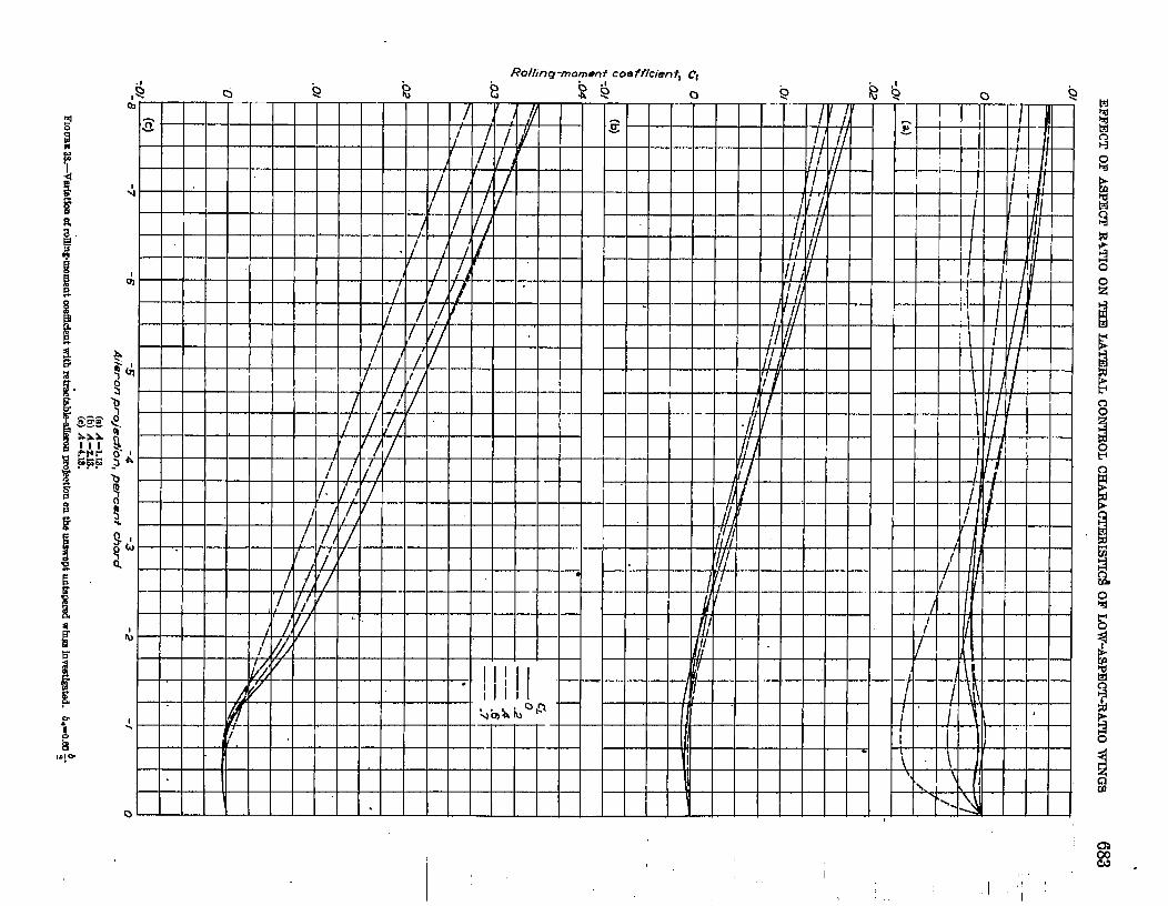
The low-aspect-ratio wings with retractable ailerons.—At equal aileron projections, the ding effectiveness of theret ract~ble ailerons (fig. 51) increased with increase in aspectrat io of the unswept wings and decreased with increase inwing sweepback. The required wing-tip heILx angle of 0.09radian (an ..ir Forc~lNa~ requirement) can usua~y be metwith the retractable ailerons on the wing model of aspectratio 4.13. The retractable ailerons on the other wings,however, produced much lower dues of pb/2V. Further-more, the rolhg effectiveness of the retractable ailerons onany of the modeIa was rather erratic over the Iift range.
Mthou.gh the values of pb/2V produced by the retractable
-.6-t
A &;Ag)6.I3
———4.13 o—-— 2.13
-s —-- —i.f3 :‘–––––2.09 45
-.4
~rp -/ ~
-.3
1-.. ,
-- ---.2 --- ---
L\
\ I 1i \ i
0 .2 .4 .6 .8Liff coefficienfi C=
. -.
-..
.-
WJrL.,,.-mrfatlmlo,a, (Ueed,rdetermhh+)withuft menk%mtofthem. . .
blrestfgatd.
aiIerons on some of the ~~~ models were not. very large,their magnitude may not be of great importance. For an ‘-”airplane having a giwn wing loading (or wing area), value9 _of the rolling velocity p may be more indicative of good cog-trd than p6/2 V because of the shorter wing span and higher

692 REPORT 109 l—NATIONAL ADVISORY COMMI~E FOR AERONAUTICS
.241
.ao
/
,/” ---.16
— #I / ‘
\ /-. *
.12
. .
A (dtq).08 0
:——z—-— P.t3 :—-- -1.13 0
.04
0 .2 . .4 .6 .8 1.0L )f f coefficient, CL
FInURE SO.-Varlat1onof estimatedwfng-tfphd[x anglew[th fIff cm4Ucfentfir the wingmodehe=qulpFMwith half mnderfm outbmrd flap atlerunsdeflwteda totir of XF.
:“A..
rolling velocities expcricnccd by such an airpIane at a givenvalue of @/2 V as the wing aspect ratio clccrcased. On thisbasis, the roIIing velocities of tbc t.hrce unswept wings andthe 45° sweptback. wing with the optimum pla.in-ret.ractable-aileron configuration are estimated to be approximatelyequal for an aileron projection of —0.08c and at the samespeed.
Comparison of spoiler and flap ailerons on the low-aspect-ratio wings,-A comparison of the rollinfyeffectivencss param-eter @1217 of the flap ailerons (obtained from fig. 50 andunplddished data) and that of the retractable ailerons in-vestigated on the same ivings (fig. 51) is s~own in figure 52.
130th types of tlilerons produced simdar trends in the vari-ation of pb/2V over the lift range (fig, 52). The half-scmispam flap aiIerons deflected a total of 20° were moreeffcc.tivc than thti spoiIer ailerons projected —O.0t3c on thesame wings, except for a limit~d range of lift co@cicnt onthe 45° sweptha,ck-wing model. The following table showsthe estimated span of 0.25c flap aiIerons deflected a total of20° that would generally equal the rolling effactiveness of a
b
( )‘{ —0.40 projcoted –0.OSC on
0“60 ~ ‘etracta~}le a“ilerOn b/2
EZ3EEEH.~tizi-lJ‘- -––– 2.0945 Opfimum s+~ed refrwcfukle
A+# “. It I
I.16
r
.12I..
1 1 I 1i tTttl
o .2 .4 .6 .6 LoLift coefficient+ CL
~fiUEE 61.—Verfatforlof e9tfnMt@dWing-tlp hellx angfe with IIft ooe~ctcnt for the WIIU
modcle eqn!ppwl mIth retrecti%bleaileron% b.-O.fU # ,nlkron projwtbrr, -0.C&.
each of the wings:
I .1 f.—I
EathnetKI man of tle.pe.fleroneto produos
A (a) mroe @/SVrm 0.00 #
retrrd+rd+t #erorm
* Cornpmteanmsdc rrlthoptimumplain retruetableallemn,Labt9
The data given in tlw previous tabIe, as well as the data offigure 52, show that retractable ~ilerons on low-aspect-rat iounswept wings arc rather ineffective when comprwcd withreasonably normal-size flap ailerons and become progres-sively worse as the wing aspect ratio is docrcascd.

6
EFFECT OF ASPECT IUTIO ON THE LATERAL CO.NTROL CHARACTERISTICS OF LOTV-ASPECT-RATIO WINGS 693
Lift weffiti~ ~
Mi ,4=1.13 A-@.(CJ.4-LB. A-r.
(b] /i-213; A-r.(d A-2.W, A-W.
S2.-CompwLwm riestbnated W.IH of ~~? pmdueed byO.MJ~rehwtabfeaQ&nqDroJectd -0.Me and by batf-semfspirr 0.25r seabid 5P aiIeroru dekted a total of W on each of
ulita~ei%ilow-nsst+atio wings. (FloP.nlkrrmda~ wereestlmotedkom unpublisheddata for N sweptlmckwbxz.1
-..
..-
.-.
—
the

694 REPORT1091—NATIO3TAL ADVISORY COMMI’EIIWZ FOR AERONAUTICS
Such a comparison is rather incomplete, lrowcver, whenthe effects of the aileron yawing moments, of the aileronhinge moments, and of compressibility are not considered.In genera.1, the yawing moments of spoiler ailerons arefavorable and would tend to increase t,he rolling effectivenessof these controls as contrasted to opposite effects exhibitdby the flap aiIerons at higl~. angles of attack. The data ofreftmmces 3 and 4 show that, the spoiler ailerons were momeffect ive than the flap ailerons when compressibility effectswere considered, and, in addition, re.fe.rrmce 9 indicates thath’ twist of the wing with spoiler controls was less than thatof the wing with flap controls.
c!ONCLUS1ONS
A low-speed wind-tunnel investigation was made todetermine the lateral .contrd characteristics of a series ofuntape.red Iow-aspect-ratio wings. Sealed flap ailerons ofvarious spans and spanwisc locations were investigated onunswept wings of aspect ratios 1.13, 2.13, 4.13, and 6.13;various projcct,ious of 0.60 -semispan retractable ailerons wereinvestigated on the unswcpL wings of aspect ratios 1.13,2.13, and 4.13 and a 45° swepthack wing. The retractd.deailc.rons investigated on the unswept wings spanned the out-board stations of each wing; whereas the pIain and steppedretractable ailerons invcstigatml on the swcptback wing werelocated at various spanwisc stations. The results of theinvestigation Ied LOthe following conclusions:
1. The variation of experimental flap-ailercm effectivenesswith aspect ratio was not accurately predicted for all spansof ailerons by any ouc of the three theoretical methods withwhich a comparison was made.
2. Flap-aiIeron effectiwmcss increased as aileron span orwing aspect ratio was increased. Roiling offcctivcncas of
the 0.50 ~ outboard flap ailerons decreased wiLh increasing
a9pcct ratio except for the low-lif t-coefmie.nt ra.ngc wherethe aspect-ratio-2. 13 wing gave somewhat higher values ofrolling effactiveness than the aspect-ratio-l. 13 wing produced.
3. At equal aiIeron projections, the. rolling effectiveness ofthe retractable ai~erons increased with increaso in aspectratio of the unswept wings and decreased with increase inwing swcepback; however, the rolliig velocities produced onthe four wings arc estimated to be approximately equal for agiven wing area (or wing loading) at the maximum aileronprojection investigated,
4. ‘Jlie effectiveness of pIain retractable ailerons on the45° sweptback wing generally increased when the spanwiselocation of- tha aileron was moved inboard.; whereas thecffcctivcnms of steppml retractal.dc ailerons on the same Ii+nggenerally increased at low and moderate angles of attackwhen their spanwise location was moved outboard. The
optimum configuration for the plain retractable aih?ron (at
the inboard location) was usually mom cff ccLivc thun the
optinl~lm coniigura~ion for the steppe’d rotractafile aileron
(at the outboard location) on the sweptback wing.
5. The addition of simulated achmting arms to the plain
and stepped .rctractable ailerons investigated tit various
spanwjse locaLions on the sweptbnr.k wing gencrrd~y temicd
to increase the aileron cflective&ss.
6. ThB effectiveness of the retractable ailerons on the
unswept wings could bc prcdic ted by an Gxisting empirical
method” for low angIca of attack; however, this empirical
metlmd was unsatisfactory for estimating Lhc cff ectivem!m
of rctractuble ailerons on the 45° swcptback wing.
7. The problems associated with adverse yawing momenta
bccom.e serious for flap ailerons well below maximum lift
coefficient for unswept wings of moderately low aapecL raLio
if partial flow separation in the linear lift rango is charac-teristic of the wings.
8. ~ generaI, tho wducs of yawing-moment coefficient C.produced by the retractable aiIerons on t.hu wings werefavorable and increased linearly with aileron projcc.Lionexcept at small proj cctions.
\
LANGLEY AERONAUTICAL LABORATORY,
NAjIONAL ADVISORY COMMITTEE FOR AERONAUTICS,LANGLEY FIELD, VA., February 8, J052.
REFERENCES
1. Stack, John, and I,hldscy, W. F.: Characteristics of Low-.tipcct -Ratio Wings at. Supercritictd h{acb Numbers. NACA [email protected],19+9. (SupersoriesNACA TN 1065.)
2. Fischel, Jack, and Tamburdlo, Vito: Investigation of Effcct’ufSpan, SpanWiseLocation, and Chordwise Location of SImilrrti onLateral Cout.rol Charact@stica of a Ta~mcd Wing. N.4C.4 TXi294, 1947.
2. Fischel, Jack, and Scheitcr, Ixxlie E.: High-Speed Wind-TunnelInvsstigat ion of an NACA 05-210 Scrnkpan Wing llquippmlwith Plug and Retractable AiIerorrs and a Full-span Slotted Flap.NAC.4 TN 1663, 1948.
4. Laitonc, Fdmund Jr., 4nd Sumtners, James L.: An Additional In-vestigation of the High-Speed Lateral-Cwltrol Charactcdstics ofSpoilers. NACA ACR 5D28, 1945.
5. Fischel, Jack, and Ivey, Margaret F.: Collection of Ted Data forL&ml Control with Full-span Flaps. NACA TN 1404 1948.
6. Scbueiter, Leslie E., and Watson, Jamw hf.: Imw-speed Wind-Tunnel Investigation of Various Plain-Spoiler Cm-@urat ions forLateral Control on a 42° Swcptkwck Wing. XACA Thr 1616,1948.
7. I.ovell,PowelJM.,Jr., and Stasi, Paul P.: A Comparison of tlw LateralControllability with Ffap and Plug Ailerons ou a Swcptl)ack-Wing Model. NACA TN 2089, 1950.
8. Lavell, Powell M., Jr.: A Compa[kon of the Lateral CouhwllaMl-ity with Flap and Plug &Ierons on a Sw@hack-Wfng Model.Having Full-Span Flaps. NACA TN 2247, 1050.
.

EFFECT OF ASPECT IL4TI0 ON THE UTEM.L CONTROL CHXRAC!TEIUSTTCS OF LOW-ASPECT-RATIO WINGS 695
!). Purser. Paul E., and McKinney, Elizabeth G.: Gomparkon ofPitching Moments Produced by Plain F@ and by Spoilers andSome Aerodynmrdc Characteristics of an h“AC.k23012 AirfoiIwith Various Types of Aileron. N.4C.\ .4CR L5C24ar 1945.
10. GilIia, Clarence L., PoIhamus, Edward C., and Gray, Joseph L., Jr.:C!harts for Determining Jet-Bound&y Corrections for CompIeteModeIs in 7- by 10-Foot CIosed Rectangtdar Wind Tunnels.YAC’.I ARR L.5G31, 1945.
11. Herriot, John G.: BIockage Corrections for Three-Dimensiorud-Flow Closed-Throat Wind Tunnels, with Consideration of theEffect of Compr&=ibiIity. NACA Rep. 995, 1950. (SuperserkXACA RM A7B28.)
12. PoIhamus, Edward C.: A SirnpIe Method of IMirnating the Sub-sonic Lift and Damping in Roll of Sweptback ‘iHngs. N.4CATX 1S62, 1949.
13. Zimmerman, C. H.: Characteristic of Clark Y .tifoik of SrnaIIAspect Rati@. N-AC.4 Rep. 431, 1932.
14. Goodman, AIes, and Brewer, Jack D.: Investigation at Law Speedsof the Effect of Aspect Ratio and Sweep on Static and YawingStabiIity Derivat ives of Untapered ‘iVii. NACA TN 1609, KM.
15. Goodman, Me% and Adair, Glenn H.: Mimation of the Damping ._ _in RoII of Wings Through the ATormd FIight Range of Lift Coef-ficient. NACA TN 1924, 1!349.
16. JTeick, Fred E., and .Jorms, Robert T.: R&.rrn6 and .4r@rsis ofN.A.C.A. Lateral Control Research. NACA Rep. 605, 1937.
17. Lowry, John G., and Schneiter, 12die E.: Estimation of EHective-nam of FIap-Type Controls on Swept hsck Wine. .NAC-4 TN. _1674, 194S.
18. DeSoung, John: Theoretical Antisymmetric Span Loading forWiis of Arbitrary Plan Format Subsonic Speeds. N.AC.4 TN ““2110, 1950.
19. DeYoung, John: Spanwise Loading for W-his and Contil surfaces “.:of Law .Aqxct Ratio. N’ACA TN’ 201 I, 1950.
20. Do&, Jules B., Jr.: Wind-TunneI Investigation of HorizontalTails. lV—Unswept PIan Form of Apect Ratio 2 and a Two- “-Dimeneiord ModeL NACA RM A8J21, 1!)%.
21. Aahkenas, L L.: The Development of a Meral-Contml Systemfor We with Large-span Ffaps. NACA TN 1015, 1946.
22. LiddelI, Robert B-: Wind-TunneI Teats of SpoiIers on Taii Surfacea.NACA ARR L5F28. 1945.