Embed Size (px)
Citation preview
Lessons Learned From Natural Gas STAR Partners
REPLACING WET SEALS WITH DRY SEALS IN CENTRIFUGAL COMPRESSORS
Executive Summary Centrifugal compressors are widely used in production and transmission of natural gas. Seals on the rotating shafts prevent the high-pressure natural gas from escaping the compressor casing. Traditionally, these seals used high-pressure oil as a barrier against escaping gas. Natural Gas STAR partners have found that replacing these “wet” (oil) seals with dry seals significantly reduces operating costs and methane emissions.
Methane emissions from wet seals typically range from 40 to 200 standard cubic feet per minute (scfm). Most of these emissions occur when the circulating oil is stripped of the gas it absorbs at the high-pressure seal face. Dry seals, which use high-pressure gas to seal the compressor, emit less methane (up to 6 scfm), have lower power requirements, improve compressor and pipeline operating efficiency and performance, enhance compressor reliability, and require significantly less maintenance.
Although dry seal conversions might not be possible on some compressors because of housing design or operational requirements, partners should select dry seals over wet seals whenever they replace or install centrifugal compressors where possible. A dry seal can save about $135,000 per year and pay for itself in as little as 14 months. One Natural Gas STAR partner who installed a dry seal on an existing compressor, for example, reduced emissions by 97 percent, from 75 to 2 Mcf per day, saving almost $80,000 per year in gas alone.
This is one of a series of Lessons Learned Summaries developed by EPA in cooperation with the natural gas industry on superior applications of Natural Gas STAR Program Best Management Practices (BMPs) and Partner Reported Opportunities (PROs).
Emissions Source
Wet oil seals
Annual Volume of Gas Lost (Mcf)
45,1201
Method for Reducing Gas
Loss
Installing dry seals
Value of Gas Saved
($/yr)
240,000
Cost of Implementation
($/yr)
135,3602
Payback
14 months3
1 Based on the difference between typical vent rates of wet and dry seals (i.e., 100 scfm versus 6 scfm) on a “beam” type compressor operating 8,000 hrs/yr. 2 Value of gas = $3.00/Mcf. 3 Based on replacement of a fully functioning wet seal with additional $73,000 in O&M cost reductions.
Wet Seals
Dry Seals
Technology Background
Wet Seals
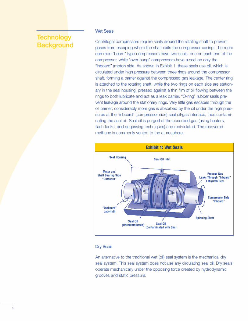
Centrifugal compressors require seals around the rotating shaft to prevent gases from escaping where the shaft exits the compressor casing. The more common “beam” type compressors have two seals, one on each end of the compressor, while “over-hung” compressors have a seal on only the “inboard” (motor) side. As shown in Exhibit 1, these seals use oil, which is circulated under high pressure between three rings around the compressor shaft, forming a barrier against the compressed gas leakage. The center ring is attached to the rotating shaft, while the two rings on each side are stationary in the seal housing, pressed against a thin film of oil flowing between the rings to both lubricate and act as a leak barrier. “O-ring” rubber seals pre-vent leakage around the stationary rings. Very little gas escapes through the oil barrier; considerably more gas is absorbed by the oil under the high pressures at the “inboard” (compressor side) seal oil/gas interface, thus contaminating the seal oil. Seal oil is purged of the absorbed gas (using heaters, flash tanks, and degassing techniques) and recirculated. The recovered methane is commonly vented to the atmosphere.
Exhibit 1: Wet Seals
Seal Housing Seal Oil Inlet
Motor and Shaft Bearing Side
“Outboard”
“Outboard” Labyrinth
Seal Oil (Uncontaminated) Seal Oil
(Contaminated with Gas)
Spinning Shaft
Compressor Side “Inboard”
Process Gas Leaks Through “Inboard”
Labyrinth Seal
Dry Seals
An alternative to the traditional wet (oil) seal system is the mechanical dry seal system. This seal system does not use any circulating seal oil. Dry seals operate mechanically under the opposing force created by hydrodynamic grooves and static pressure.
2
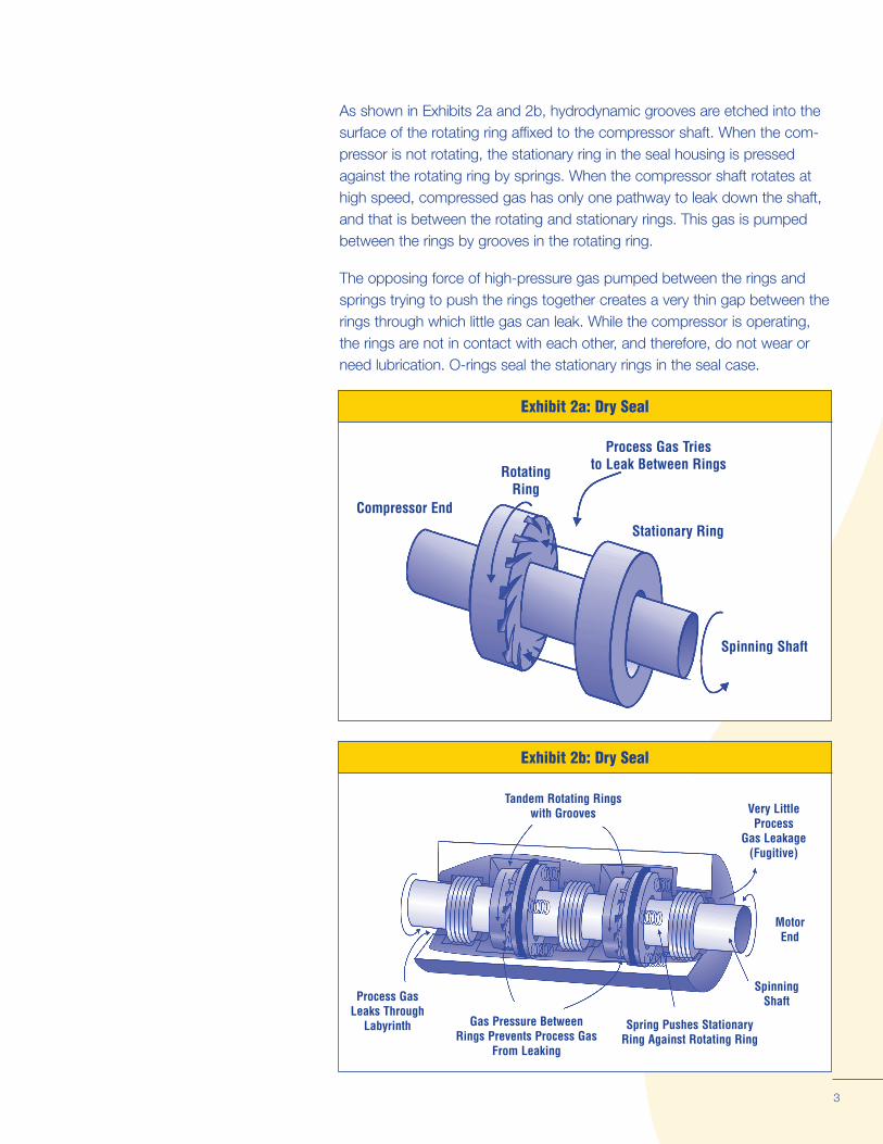
As shown in Exhibits 2a and 2b, hydrodynamic grooves are etched into the surface of the rotating ring affixed to the compressor shaft. When the compressor is not rotating, the stationary ring in the seal housing is pressed against the rotating ring by springs. When the compressor shaft rotates at high speed, compressed gas has only one pathway to leak down the shaft, and that is between the rotating and stationary rings. This gas is pumped between the rings by grooves in the rotating ring.
The opposing force of high-pressure gas pumped between the rings and springs trying to push the rings together creates a very thin gap between the rings through which little gas can leak. While the compressor is operating, the rings are not in contact with each other, and therefore, do not wear or need lubrication. O-rings seal the stationary rings in the seal case.
Exhibit 2a: Dry Seal
3
Exhibit 2b: Dry Seal
Tandem Rotating Rings with Grooves Very Little
Process Gas Leakage
(Fugitive)
Motor End
Spinning Shaft
Spring Pushes Stationary Ring Against Rotating Ring
Gas Pressure Between Rings Prevents Process Gas
From Leaking
Process Gas Leaks Through
Labyrinth
Spinning Shaft
Stationary Ring
Process Gas Tries to Leak Between RingsRotating
Ring Compressor End
Gas Leak Rates.
Mechanically Simpler.
Reduced Power Consumption.
Improved Reliability
Lower Maintenance.
Elimination of Oil Leakage from Wet Seals.
Economic and Environmental Benefits
Putting two or more of these dry seals together in series, as shown in Exhibit 2b, is called “tandem dry seals,” and is very effective in reducing gas leak-age. This type of seal has less than one percent of the leakage of a wet seal system vented into the atmosphere and costs considerably less to operate.
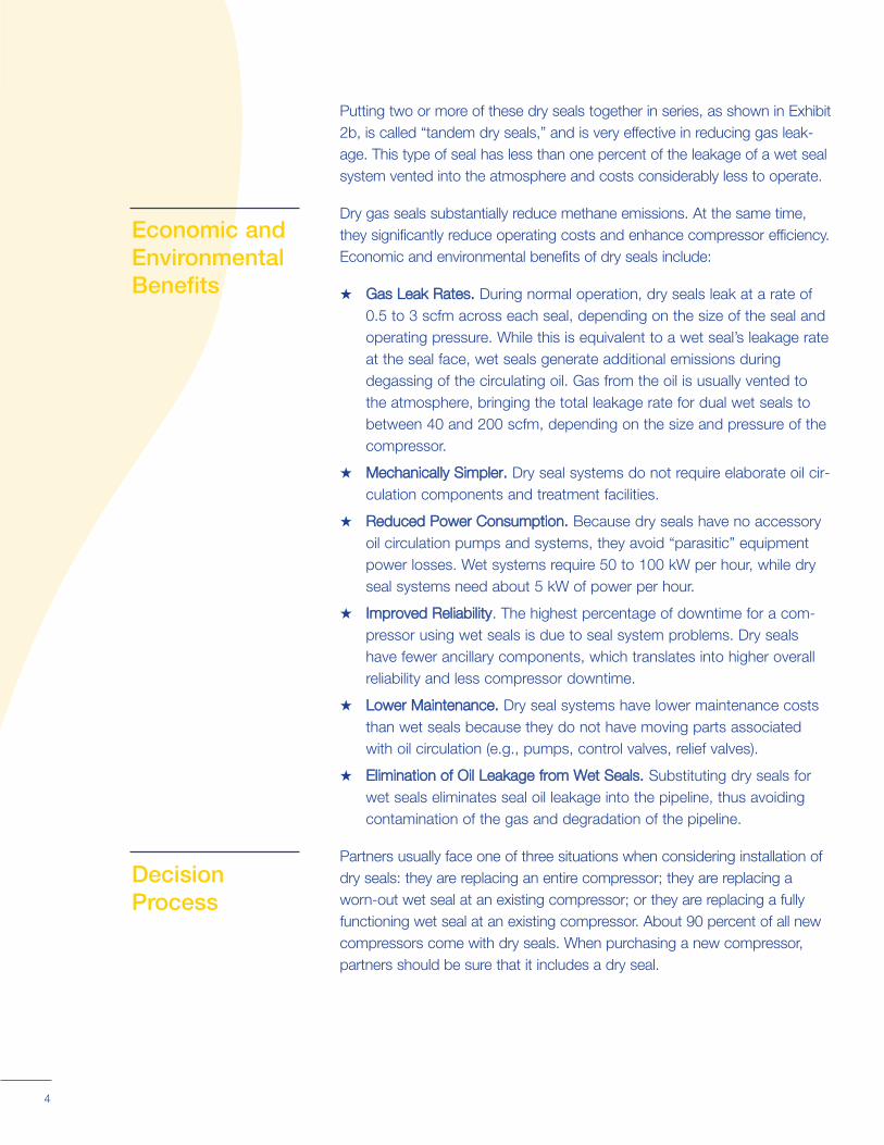
Dry gas seals substantially reduce methane emissions. At the same time, they significantly reduce operating costs and enhance compressor efficiency. Economic and environmental benefits of dry seals include:
★ Gas Leak Rates. During normal operation, dry seals leak at a rate of 0.5 to 3 scfm across each seal, depending on the size of the seal and operating pressure. While this is equivalent to a wet seal’s leakage rate at the seal face, wet seals generate additional emissions during degassing of the circulating oil. Gas from the oil is usually vented to the atmosphere, bringing the total leakage rate for dual wet seals to between 40 and 200 scfm, depending on the size and pressure of the compressor.
★ Mechanically Simpler. Dry seal systems do not require elaborate oil circulation components and treatment facilities.
★ Reduced Power Consumption. Because dry seals have no accessory oil circulation pumps and systems, they avoid “parasitic” equipment power losses. Wet systems require 50 to 100 kW per hour, while dry seal systems need about 5 kW of power per hour.
★ Improved Reliability. The highest percentage of downtime for a compressor using wet seals is due to seal system problems. Dry seals have fewer ancillary components, which translates into higher overall reliability and less compressor downtime.
★ Lower Maintenance. Dry seal systems have lower maintenance costs than wet seals because they do not have moving parts associated with oil circulation (e.g., pumps, control valves, relief valves).
★ Elimination of Oil Leakage from Wet Seals. Substituting dry seals for wet seals eliminates seal oil leakage into the pipeline, thus avoiding contamination of the gas and degradation of the pipeline.
Partners usually face one of three situations when considering installation of Decision dry seals: they are replacing an entire compressor; they are replacing a
Process worn-out wet seal at an existing compressor; or they are replacing a fully functioning wet seal at an existing compressor. About 90 percent of all new compressors come with dry seals. When purchasing a new compressor, partners should be sure that it includes a dry seal.
4
Step 1: Identify candidates for wet seal replacement.
The analysis for replacing a wet seal on an existing compressor should consider the methane emissions savings along with capital and operational costs and benefits. The economics for replacing operating wet seals are compelling, and wherever possible, partners should undertake such replacements. The decision process below is a guideline for determining candidates, benefits,
Four Steps for Converting to Dry Seals:
1. Identify candidates for wet seal replacement.
2. Estimate the savings of a dry seal retrofit.
3. Determine the costs for conversion to dry seals.
4. Compare costs to savings.
and costs for replacing wet seals with dry seals in compressors.
Step 1: Identify candidates for wet seal replacement. Operators should make a comprehensive inventory and technical evaluation of their existing compressors. Factors to consider include compressor type, age, hardware, and operating conditions. All wet seal compressors should be identified and evaluated for dry seals. When deciding which compressors are candidates for replacement of the wet seal, consider the following:
★ Dry seals can be used for compressors up to 3,000 psi safely; applications of 1,500 psi are routine. Dry seals, however, might not be safe for higher pressures. Further, dry seals are not appropriate for applications with temperatures above 300 to 400 degrees Fahrenheit (due to O-ring material limitations)1. Some compressor designs prohibit the retrofit of dry seals.
★ Some older compressors might be at the end of their economic life and, thus, are candidates for complete replacement rather than a seal replacement. This is usually determined while planning a major over-haul, when operating and maintenance (O&M) costs for the old compressor are projected to increase to a level much greater than O&M costs for a new unit. Some clues that this stage might have been reached include sudden increases in the frequency and magnitude of unscheduled maintenance and the unavailability of replacement parts or lack of technical support.
Centrifugal compressors that meet the Step 1 criteria should be evaluated further as follows.
5
SStteepp 22:: EEssttiimmaattee tthhee ssaavviinnggss
frthe majority of methane loss frtions in methane gas loss. T
ooff aa ddrryy sseeaall rreet
om the seal oil degassing unit by bagging or using a high flow samplerom their wet seal compr
o
trrooffiitt..
. essors at the vent
estimate these savings, partners can measur
In general, the majority of savings from replacing a wet seal with a dry seal are attributable to reduc
e
1John Stahley, Dresser-Rand Co.
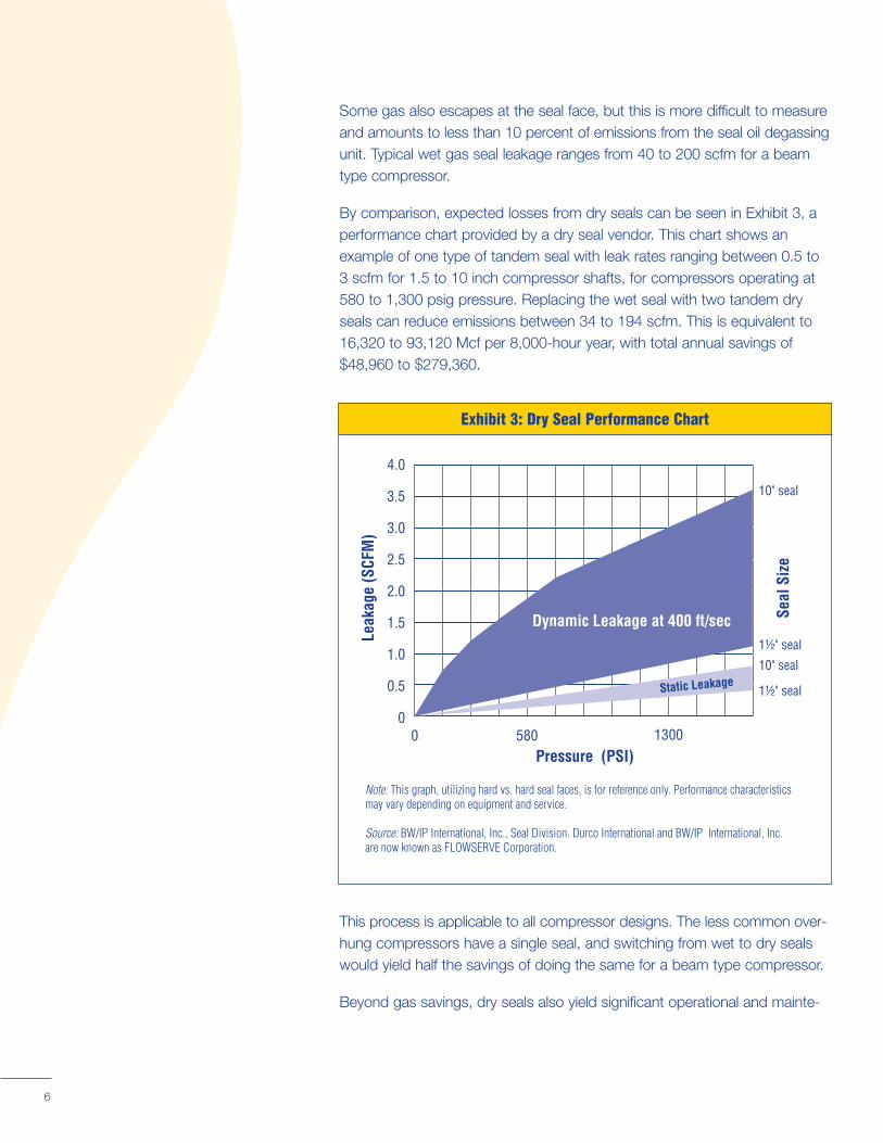
Some gas also escapes at the seal face, but this is more difficult to measure and amounts to less than 10 percent of emissions from the seal oil degassing unit. Typical wet gas seal leakage ranges from 40 to 200 scfm for a beam type compressor.
By comparison, expected losses from dry seals can be seen in Exhibit 3, a performance chart provided by a dry seal vendor. This chart shows an example of one type of tandem seal with leak rates ranging between 0.5 to 3 scfm for 1.5 to 10 inch compressor shafts, for compressors operating at 580 to 1,300 psig pressure. Replacing the wet seal with two tandem dry seals can reduce emissions between 34 to 194 scfm. This is equivalent to 16,320 to 93,120 Mcf per 8,000-hour year, with total annual savings of $48,960 to $279,360.
0 580 Pressure
Leak
age
(SCF
M)
Seal
Siz
e
1300
1½" seal
1½" seal
10" seal
10" seal
4.0
3.5
3.0
2.5
2.0
1.5
1.0
0.5
0
Note: This graph, utilizing hard vs. hard seal faces, is for reference only. Performance characteristics may vary depending on equipment and service.
Source: BW/IP International, Inc., Seal Division. Durco International and BW/IP are now known as FLOWSERVE Corporation.
Exhibit 3: Dry Seal Performance Chart
(PSI)
International, Inc.
Dynamic Leakage at 400 ft/sec
Static Leakage
This process is applicable to all compressor designs. The less common over-hung compressors have a single seal, and switching from wet to dry seals would yield half the savings of doing the same for a beam type compressor.
Beyond gas savings, dry seals also yield significant operational and mainte-
6
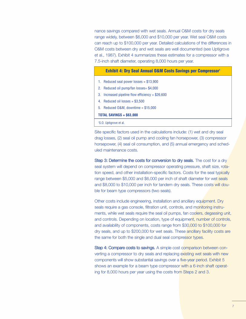
nance savings compared with wet seals. Annual O&M costs for dry seals range widely, between $6,000 and $10,000 per year. Wet seal O&M costs can reach up to $100,000 per year. Detailed calculations of the differences in O&M costs between dry and wet seals are well documented (see Uptigrove et al., 1987). Exhibit 4 summarizes these estimates for a compressor with a 7.5-inch shaft diameter, operating 8,000 hours per year.
Exhibit 4: Dry Seal Annual O&M Costs Savings per Compressor1
1. Reduced seal power losses = $13,900
2. Reduced oil pump/fan losses= $4,000
3. Increased pipeline flow efficiency = $26,600
4. Reduced oil losses = $3,500
5. Reduced O&M, downtime = $15,000
TOTAL SAVINGS = $63,000
1S.O. Uptigrove et al.
7
Site specific factors used in the calculations include: (1) wet and dry seal drag losses, (2) seal oil pump and cooling fan horsepower, (3) compressor horsepower, (4) seal oil consumption, and (5) annual emergency and sched-
SStteepp 33:: DDeetteerrmmiinnee tthhee ccoossttss ffoorr ccoonnvveerrssiioonn ttoo ddrryy sseeaallss.. The cost for a dry seal system will depend on compressor operating pr
ing for 8,000 hours per year using the costs frshows an example for a beam type comprcomponents will show substantial savings over a five-year period.
essure, shaft size, rotation speed, and other installation-specific factors. Costs for the seal typically range between $5,000 and $6,000 per inch of shaft diameter for wet seals and $8,000 to $10,000 per inch for tandem dry seals. These costs will dou-
Other costs include engineering, installation and ancillary equipment. Dry seals require a gas console, filtration unit, controls, and monitoring instruments, while wet seals require the seal oil pumps, fan coolers, degassing unit, and controls. Depending on location, type of equipment, number of controls, and availability of components, costs range from $30,000 to $100,000 for dry seals, and up to $200,000 for wet seals. These ancillary facility costs are the same for both the single and dual seal compressor types.
SStteepp 44:: CCoommppaarree ccoo
om Steps 2 and 3. essor with a 6-inch shaft operat
Exhibit 5
ssttss ttoo ssaavviinnggss.. A simple cost comparison between converting a compressor to dry seals and replacing existing wet seals with new
uled maintenance costs.
ble for beam type compressors (two seals).
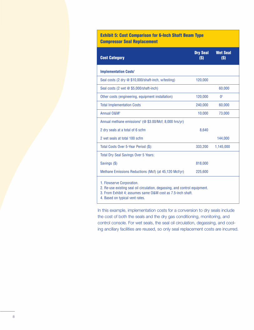
Exhibit 5: Cost Comparison for 6-Inch Shaft Beam Type Compressor Seal Replacement
Dry Seal Wet Seal Cost Category ($) ($)
Implementation Costs1
Seal costs (2 dry @ $10,000/shaft-inch, w/testing) 120,000
Seal costs (2 wet @ $5,000/shaft-inch) 60,000
Other costs (engineering, equipment installation) 120,000 02
Total Implementation Costs 240,000 60,000
Annual O&M3 10,000 73,000
Annual methane emissions4 (@ $3.00/Mcf; 8,000 hrs/yr)
2 dry seals at a total of 6 scfm 8,640
2 wet seals at total 100 scfm 144,000
Total Costs Over 5-Year Period ($): 333,200 1,145,000
Total Dry Seal Savings Over 5 Years:
Savings ($) 818,000
Methane Emissions Reductions (Mcf) (at 45,120 Mcf/yr) 225,600
1. Flowserve Corporation. 2. Re-use existing seal oil circulation, degassing, and control equipment. 3. From Exhibit 4; assumes same O&M cost as 7.5-inch shaft. 4. Based on typical vent rates.
In this example, implementation costs for a conversion to dry seals include the cost of both the seals and the dry gas conditioning, monitoring, and control console. For wet seals, the seal oil circulation, degassing, and cooling ancillary facilities are reused, so only seal replacement costs are incurred.
8
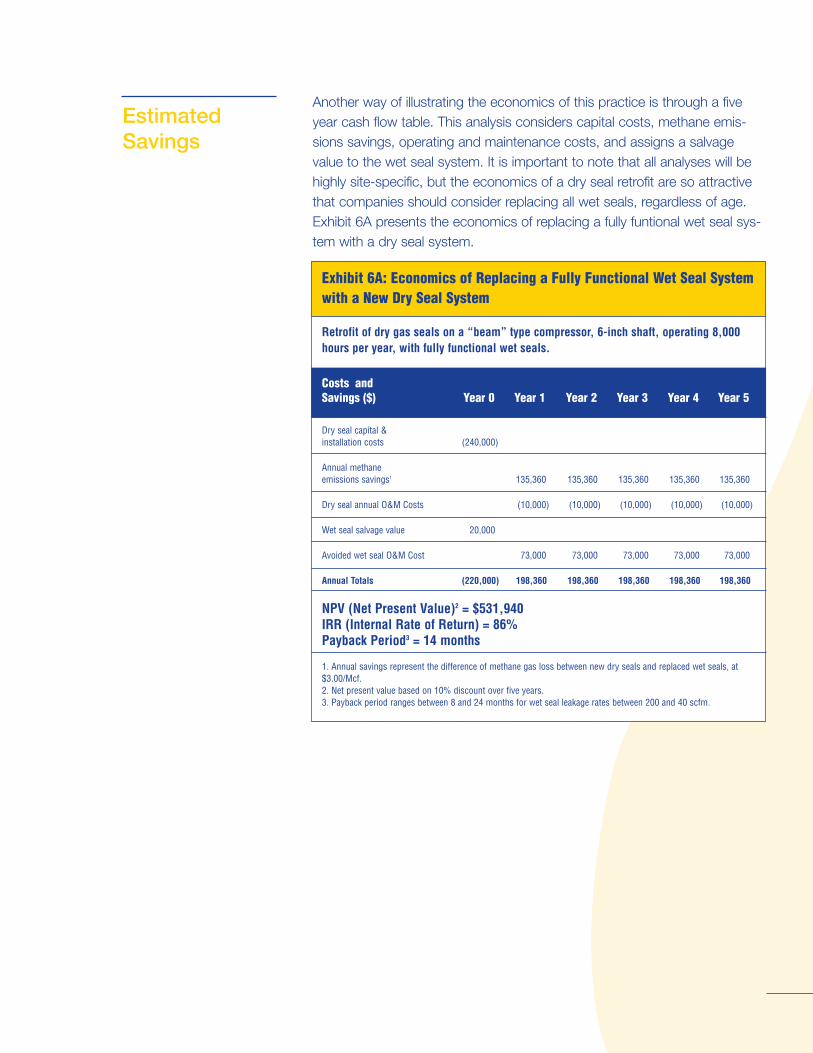
Another way of illustrating the economics of this practice is through a fiveEstimated year cash flow table. This analysis considers capital costs, methane emis-
Savings sions savings, operating and maintenance costs, and assigns a salvage value to the wet seal system. It is important to note that all analyses will be highly site-specific, but the economics of a dry seal retrofit are so attractive that companies should consider replacing all wet seals, regardless of age. Exhibit 6A presents the economics of replacing a fully funtional wet seal system with a dry seal system.
9
Exhibit 6A: Economics of Replacing a Fully Functional Wet Seal System with a New Dry Seal System
Retrofit of dry gas seals on a “beam” type compressor, 6-inch shaft, operating 8,000 hours per year, with fully functional wet seals.
Costs and Savings ($) Year 0 Year 1 Year 2 Year 3 Year 4 Year 5
Dry seal capital & installation costs (240,000)
Annual methane emissions savings1 135,360 135,360 135,360 135,360 135,360
Dry seal annual O&M Costs (10,000) (10,000) (10,000) (10,000) (10,000)
Wet seal salvage value 20,000
Avoided wet seal O&M Cost 73,000 73,000 73,000 73,000 73,000
Annual Totals (220,000) 198,360 198,360 198,360 198,360 198,360
NPV (Net Present Value)2 = $531,940 IRR (Internal Rate of Return) = 86% Payback Period3 = 14 months
1. Annual savings represent the difference of methane gas loss between new dry seals and replaced wet seals, at $3.00/Mcf. 2. Net present value based on 10% discount over five years. 3. Payback period ranges between 8 and 24 months for wet seal leakage rates between 200 and 40 scfm.
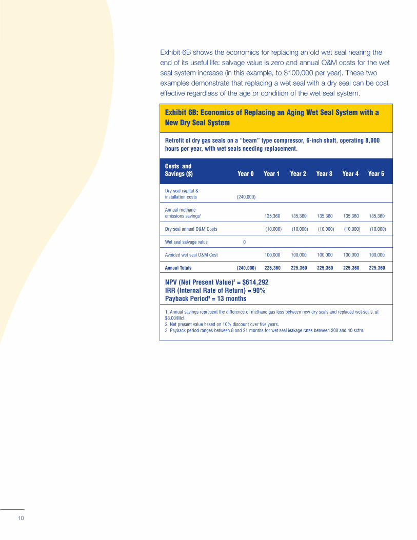
Exhibit 6B shows the economics for replacing an old wet seal nearing the end of its useful life: salvage value is zero and annual O&M costs for the wet seal system increase (in this example, to $100,000 per year). These two examples demonstrate that replacing a wet seal with a dry seal can be cost effective regardless of the age or condition of the wet seal system.
Exhibit 6B: Economics of Replacing an Aging Wet Seal System with a New Dry Seal System
Retrofit of dry gas seals on a “beam” type compressor, 6-inch shaft, operating 8,000 hours per year, with wet seals needing replacement.
Costs and Savings ($) Year 0 Year 1 Year 2 Year 3 Year 4 Year 5
Dry seal capital & installation costs (240,000)
Annual methane emissions savings1 135,360 135,360 135,360 135,360 135,360
Dry seal annual O&M Costs (10,000) (10,000) (10,000) (10,000) (10,000)
Wet seal salvage value 0
Avoided wet seal O&M Cost 100,000 100,000 100,000 100,000 100,000
Annual Totals (240,000) 225,360 225,360 225,360 225,360 225,360
NPV (Net Present Value)2 = $614,292 IRR (Internal Rate of Return) = 90% Payback Period3 = 13 months
1. Annual savings represent the difference of methane gas loss between new dry seals and replaced wet seals, at $3.00/Mcf. 2. Net present value based on 10% discount over five years. 3. Payback period ranges between 8 and 21 months for wet seal leakage rates between 200 and 40 scfm.
10
LessonsLearned
Partners can achieve significant cost savings and emissions reductions by converting to dry seal technology. Partners offer the following lessons learned when changing to dry seals:
★� Dry seals are considered safer to operate than wet seals, because they eliminate the need for a high pressure oil system.
★� To make the switch to dry seals most efficiently, schedule the conversion for a normal downtime period to avoid disrupting operations.
★� When determining the benefits of a seal replacement, partners should take into account that properly installed and maintained dry seals can last more than twice as long as wet seals.
★� If the wet seal is near the end of its useful life, a straightforward cost analysis between new seal systems will favor the dry seal. Even if the existing wet seal has substantial remaining useful life, the operational characteristics of dry seals will provide significant savings and could justify early replacement.
★� Given the clear economic advantages of dry seals, they should be installed wherever it is technically feasible.
★� Ninety percent of all new compressors now have dry gas seal systems. Dry seals should be the technology of choice for all new compressors.
★ After replacing wet seals with dry seals, record emissions reductions in
11
annual reports submitted as part of the Natural Gas STAR Program.
ReferReferences Canadian Association of Petroleum Producers. Options for Reducing Methane and VOC Emissions from Upstream Oil and Gas Operations. December 1993.
Henderson, Carolyn. U.S. EPA Natural Gas STAR Program. Personal contact.
Hesje, R.C. and R.A. Peterson. Mechanical Dry Seal Applied to Pipeline (Natural Gas) Centrifugal Compressors. American Society of Mechanical Engineering. Gas Turbine Conference and Exhibition. June 1984.
Kennedy, J.L. Oil and Gas Pipeline Fundamentals, Second Edition. PennWell Books. 1993.
Klosek, Marty. Flowserve Corporation. Bridgeport, New Jersey. Personal contact.
Ronsky, N. Daryl; Harris, T.A.; Conquergood, C. Peter; and Davies, I. An Effective System for Sealing Toxic Gases in Centrifugal Compressors. American Society of Mechanical Engineers Gas Turbine Conference and Exhibition. June 1987.
Sears, John. Personal contact.
Stahley, John. Dresser-Rand Company. Olean, New York. Personal contact.
Tingley, Kevin. U.S. EPA Natural Gas STAR Program. Personal contact.
Uptigrove, S.O.; Harris, T.A.; and Holzner, D.O. Economic Justification of Magnetic Bearings and Mechanical Dry Seals for Centrifugal Compressors. American Society of Mechanical Engineers Gas Turbine Conference and Exhibition. June 1987.

November 2003 EP
W1200 Pennsylvania AAir and Radiation (6202J) EnvirUnited States
1EP
A430-B-03-012
ashington, DC 20460 ve., NW
onmental Pr
A otection Agency