Embed Size (px)
Citation preview


Replacements for Chromic Acid Anodising in Bonded
Structures
G.W.Critchlow1, K.A.Yendall1, I.A.Ashcroft2, T.Cartwright1, V.Shenoy2
and R.H.Dahm1
1Department of Materials2Wolfson School
Loughborough University, UK
Summary of Presentation
1. Introduction to structural metal bonding2.
Pretreatment
options –
importance of CAA
3.
Alternatives:
4.
Concluding remarks
Grit-blast plus hot water immersion plus silane
DC phosphoric-sulphuric acid anodising
DC boric-sulphuric acid anodising
EPAD plus SAAACDC anodising –
the state-of-the-art -
adhesion plus fatigue

1. Introduction
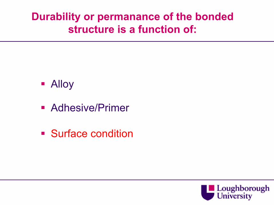
Durability or permanance
of the bonded structure is a function of:
Alloy
Adhesive/Primer
Surface condition

2. Pretreatment
options
Mechanical (degrease, grit-blast, laser texturing, cryoblasting)
Chemical (acid etch, conversion coating)
Electrochemical (anodic oxidation)
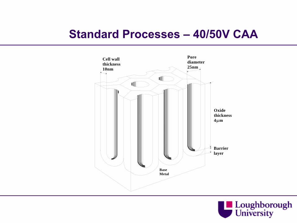
Standard Processes –
40/50V CAA
Barrier layer
Pore diameter25nm
Cell wallthickness10nm
Base Metal
Oxide thickness4μm


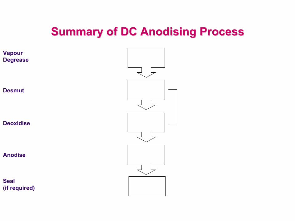
VapourDegrease
Desmut
Deoxidise
Anodise
Seal(if required)
Summary of DC Anodising ProcessSummary of DC Anodising Process

CAA 40/50V Anodising Process
Vapour Degrease
Optional Seal
Rinse- DI Water
Acid Etch
Rinse- DI Water
Alkaline Clean
Rinse- DI Water
Anodise Optional Rinse
Hot Air Dry
IsoprepIsoprep 4444 FPL EtchFPL Etch CAACAA SealSeal
Solvent Wipe
MEK
60g/l Concentration (pH 9.3 –10.45)
10 minute Submersion
60°C
60g/l – Na2 Cr2 O7 166ml/l – H2 SO4 1.5g/l – Al
30 minute Submersion
60°C
30.5 – 50.0g/l
35 – 45 minute Anodising
40°C
DI Water
15 minute Submersion
Min 96°C
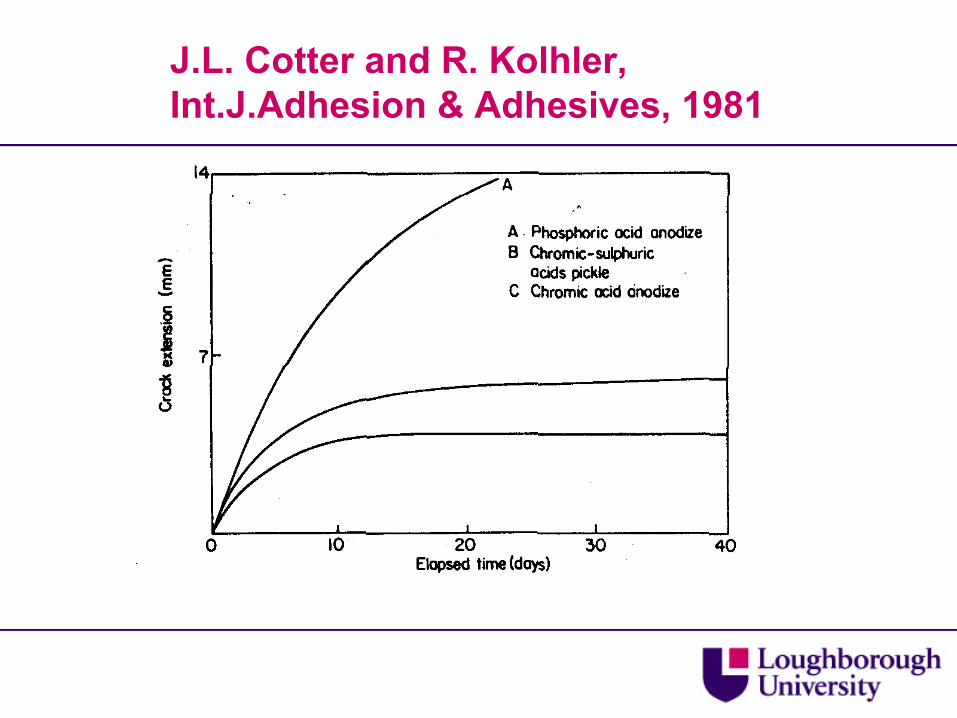
J.L. Cotter and R. Kolhler, Int.J.Adhesion & Adhesives, 1981

Disadvantages of CAA
There are health & safety and environmental issues associated with the use of hexavalent chromium.
Process is highly complex and time consuming to completion – costly.

3. ALTERNATIVES
3.1 Grit-blast plus hot water immersion plus silane

Degreasein Alconox
Grit –blast50 μm alumina
Water immersion40ºC or 50ºC
1% solutionof silane
Dry
Summary of Grit-blast plus Hot Water Immersion plus Silane
Process

eg. Underhill, Rider and DuQuesnay, Proc.Euradh
2002, Glasgow, UK
3.2 DC Phosphoric-sulphuric Acid Anodising (PSA)
PSA
Developed by Airbus (Germany)
Presented at 1996 AGARD Symposium by Matz et al


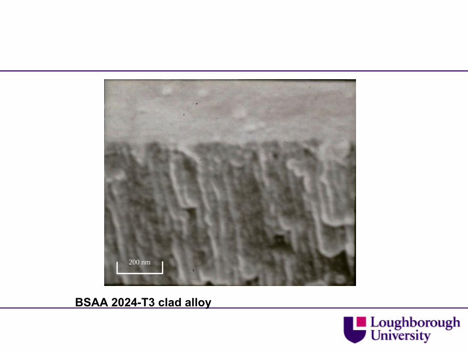
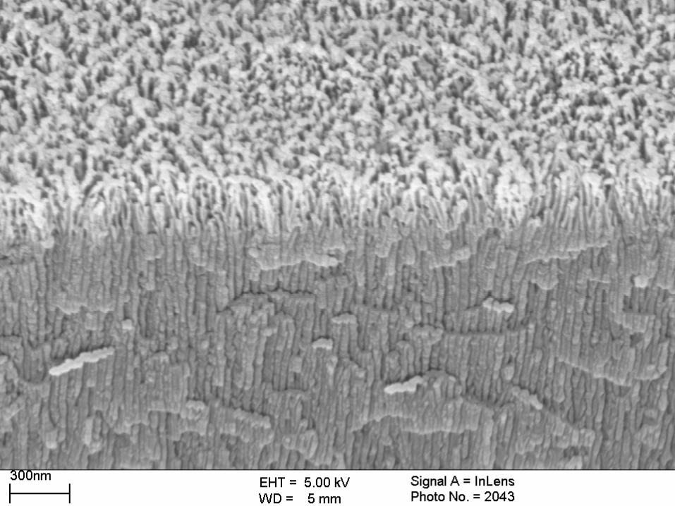
3.3 Modified Boric-sulphuric acid anodising (BSAA)

Standard BSAA processStandard BSAA process
B arrier layer
P ore d iam eter10 nm
C ell w allth ickness10nm
B ase M etal
O xide th ickness3 μm

BSAA 2024-T3 clad alloy
200 nm
BSAA 2024-T3 clad alloy
200 nm

0
5
10
15
20
25
30
35
40
45
0 20 40 60 80 100 120 140 160 180 200
Exopsure Time (hours)
Crac
k ex
tens
ion
(mm
)
Wedge test results for BSAA exposed to 60Wedge test results for BSAA exposed to 60°°C and 100% RH using 2024C and 100% RH using 2024--T3 clad alloy.T3 clad alloy.

Varied ParametersVaried Parameters
Deoxidise Bath Temp. Anodising Voltage
Post- Treatments
ElectrolyteConcentration
Number of Deoxidisers tried
Electrolytic Phosphoric Acid Deoxidiser
Varied between 25 – 40 O C
Bath Temp. 35O C
Varied between 15 – 30V
Higher voltages show limited improvement
Treatment after Anodising
Phosphoric acid dip
Boric Acid 2.5 – 10 g/l Sulphuric Acid 20 – 60g/l
No improvement compared to standard BSAA

200 nm
STEM micrograph of Electrolytic Phosphoric acid deoxidised on clad 2024 alloy

200 nm
STEM micrograph of Electrolytic Phosphoric acid deoxidised followed by BSAA on clad 2024 alloy

Variations In Electrolytic Bath Temperature
Standard temperature
200 nm200 nm
350 C.

0
10
20
30
40
50
60
0 10 20 30 40 50 60 70 80 90 100
CAA 40 /50V Tri-acid + BSAA Pyrene 7-77 @ 2 5 C + BSAAPyrene 7-77 @ 50 C + BSAA Chemcid 2 218 + BSAA Pyrene 14 -73 + BSAA Pho spho ric Acid Electro lytic Deoxid ise + BSAA Phospho ric Acid Electro lytic Deoxid ise + BSAA + PAD Tri-acid + BSAA + PADTri-acid + BSAA @3 5 C Tri-acid + BSAA @20 V Tri-acid + BSAA @25VBSAA (25g / l Sulp huric, 10 g /l Bo ric) BSAA p lus g rit -b las ted

BSAA Summary
Standard BSAA treatment proved to be inadequate as a pretreatment for bonding in comparison to the CAA control.
A number of modified BSAA alternatives are available which give the required surface topography and equivalent mechanical performance relative to that of the CAA process
However, processes are complex and times are slow

3.4 EPAD plus SAA process

32
Anodic Oxide Morphology Anodic Oxide Morphology
EPAD –
SAA Anodised
EPAD –
SAA Anodised –
PAD

34
Wedge Test ResultsWedge Test Results
0
10
2 0
3 0
4 0
5 0
6 0
7 0
CAA 4 0 / 5 0 V ( Na OH) + SAA 4 0 g / l2 6 °C
( E P AD) + SAA 4 0 g / l2 6 °C
( E P AD) + SAA 4 0 g / l3 5 °C
( E P AD) + SAA 4 0 g / l3 5 °C + ( P AD)
( E P AD) + SAA 1 8 0 g / l2 0 °C
( E P AD) + SAA 1 8 0 g / l3 5 °C
100 hours24 hours5 hoursIo
35
EPAD plus SAA Summary EPAD plus SAA Summary
EPAD Serves Two FunctionsClean/deoxidiseModify the surface aid adhesion
Duplex oxide formed which aids primer penetration and acts as barrier oxide to improve corrosion resistance
Comparable initial joint strengths and durability have been demonstrated compared with CAA

3.5 ACDC process

AC offers:Degrease only requiredOpen porous structureRapid processing
DC offers:Thick, compact film

Objective
To produce an AC/DC film in a single electrolyte at a constant temperature with approx 300
nm of outer porous oxide and >1 micrometre of inner dense oxide.

Variable parameters
Parameter AC DC
Electrolyte mixed sulphuric-phosphoric
Voltage (V) 50Hz, 10-20 <25
Time (s) 120-240 600
Temperature (°C)
RT-50 RT-50

Surface after AC anodising
5s AC anodising 30s AC anodising
degreased-only

120s AC anodising 240s AC anodising
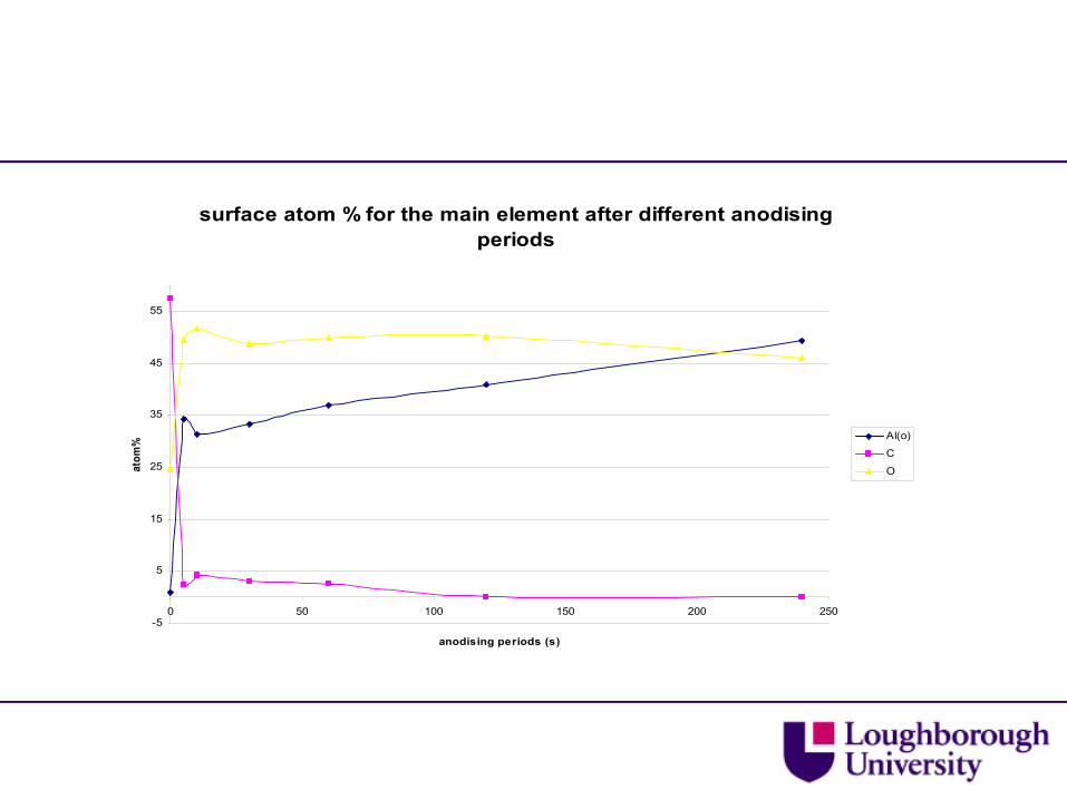
surface atom % for the main element after different anodising periods
-5
5
15
25
35
45
55
0 50 100 150 200 250
anodising periods (s)
atom
% Al(o)
C
O

surface atom% for second element after differents anodising periods
-0.5
1.5
3.5
5.5
7.5
9.5
11.5
13.5
15.5
17.5
19.5
0 50 100 150 200 250
anodising periods (s)
atom
%
P
S
Cl
K
Mg(o)
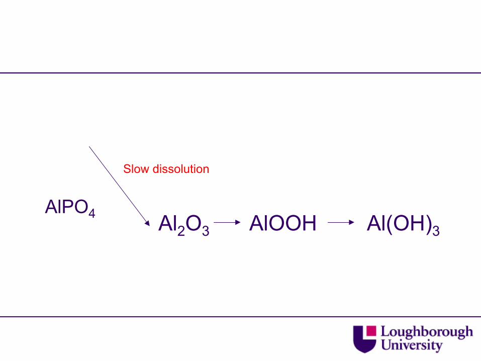
AlPO4 Al2
O3 AlOOH Al(OH)3
Slow dissolution

Influence of DC voltage
Film thickness Vs Voltage (10m)
0
0.5
1
1.5
2
0 5 10 15 20 25 30
Voltage / V
Th
ickn
ess
/ m
icro
ns

10v AC, 120 s: 20v DC, 600s @35°C


Crack extension as a function of time
0
1
2
3
4
5
6
0 4 8 12 16 20 24 28 32 36 40 44 48 52 56 60 64 68 72 76 80 84 88 92 96
exposure time / hours
crac
k ex
tens
ion
/ mm

0
0.5
1
1.5
2
2.5
3
0 4 8 12 16 20 24 28 32 36 40 44 48 52 56 60 64 68 72 76 80 84 88 92 96
Exposure time / hours
Gc
/ KJm
-2
10 120 35
10 120 50
10 240 35
10 240 50
15 120 35
15 240 35
CAA

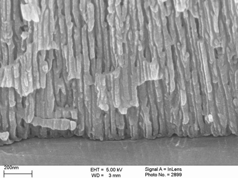
Results -
FEGSEM Images
(a) AC/DC plan(b) SAA plan(c) AC/DC plan higher magnification(d) SAA plan higher magnification(e) AC/DC cross section(f) SAA cross section
(a) (b)
(e)(d) (f)
(c)
Oxide Thickness~ 1.8μm Oxide
Thickness~ 8μm

0
1000
2000
3000
4000
5000
6000
7000
8000
9000
10000
Ultimate Failure Load (N)
Degrease Grit Blast SAA AC/DC
Pretreatment Initial Bond Strength 1 Week Exposure 1 Month Exposure2 Month Exposure 3 Month Exposure

ACDC Summary
A two-stage anodisation process has been developed to facilitate interphase formation without compromising corrosion protection.
The process is simple, fast and robust.
Initial results show promising adhesion and corrosion performance.
Additional studies are underway to further validate this process.

Fatigue
Bare metal
Bonded Joints
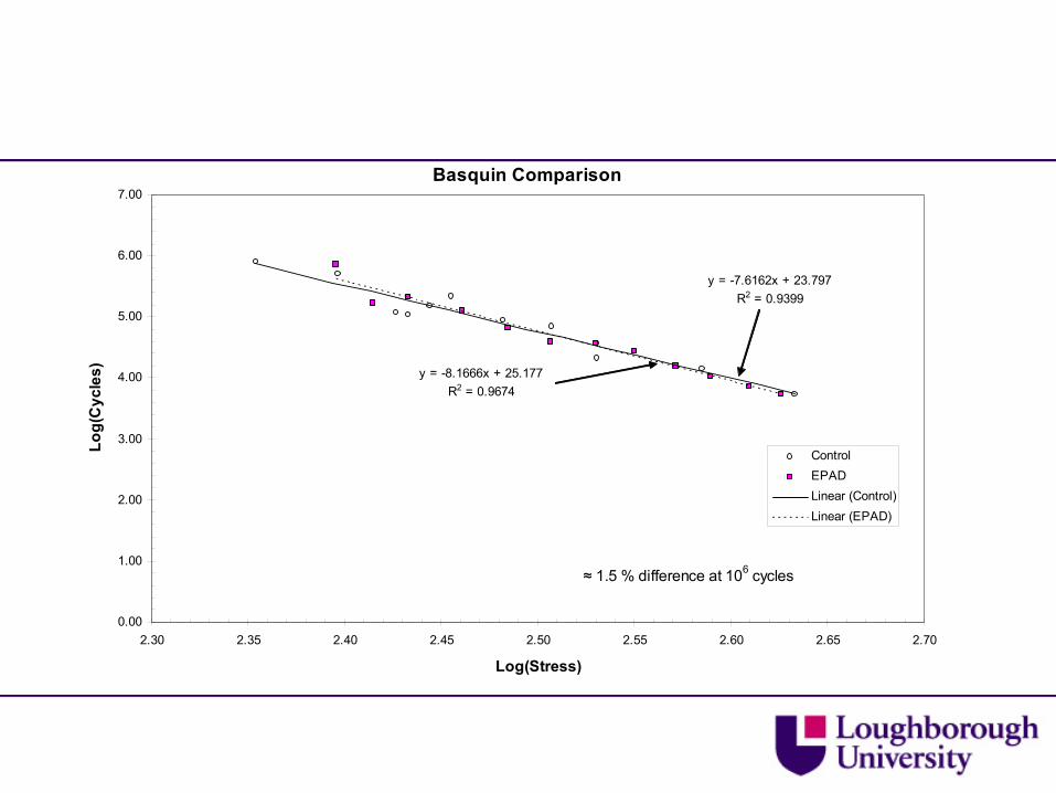
Basquin Comparison
y = -7.6162x + 23.797R2 = 0.9399
y = -8.1666x + 25.177R2 = 0.9674
0.00
1.00
2.00
3.00
4.00
5.00
6.00
7.00
2.30 2.35 2.40 2.45 2.50 2.55 2.60 2.65 2.70
Log(Stress)
Log(
Cyc
les)
ControlEPADLinear (Control)Linear (EPAD)
≈ 1.5 % difference at 106 cycles

Basquin Comparison
y = -6.9664x + 22.235R2 = 0.855
y = -7.6162x + 23.797R2 = 0.9399
0.00
1.00
2.00
3.00
4.00
5.00
6.00
7.00
2.30 2.35 2.40 2.45 2.50 2.55 2.60 2.65 2.70
Log(Stress)
Log(
Cyc
les)
ControlACDCLinear (ACDC)Linear (Control)
≈ 2 % difference at 106 cycles

Types of load interaction effects
Mean load change
Load ratio change
Mixed effects
Complex loading

SEM damage characterisation
Damage in the glue-line
1µm
Adherend
Imaginary boundary between fillet and glue-line
Damage in the fillet
Damage in the glue-line
Damaged adhesiveUndamaged adhesive
Fractured surface


Damage mechanics
Fatigue lifetime
2mp )(1mdN/dD υ=
FEA and Fatigue damage calculation.
Geometry
Material property
Damage evolution law
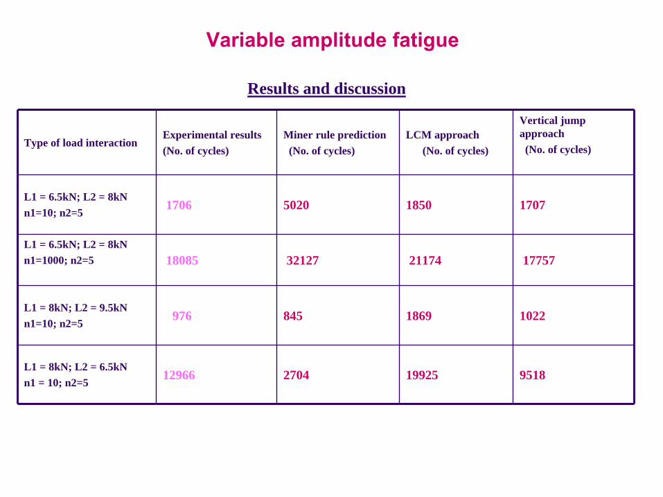
Variable amplitude fatigue
Type of load interactionExperimental results (No. of cycles)
Miner rule prediction (No. of cycles)
LCM approach (No. of cycles)
Vertical jump approach(No. of cycles)
L1 = 6.5kN; L2 = 8kNn1=10; n2=5 1706 5020 1850 1707
L1 = 6.5kN; L2 = 8kNn1=1000; n2=5 18085 32127 21174 17757
L1 = 8kN; L2 = 9.5kNn1=10; n2=5 976 845 1869 1022
L1 = 8kN; L2 = 6.5kNn1 = 10; n2=5 12966 2704 19925 9518
Results and discussion

AC DC against CAA surface pre-treatment
Static strength
Cycles to failure for max. fatigue load of 60% of static strength
0
2
4
6
8
10
12
14
0 500 1000 1500
Conditioning [ no. of hours]
Stat
ic s
treng
th [k
N] v
AC DCCAA
1.E+01
1.E+02
1.E+03
1.E+04
1.E+05
0 500 1000
Cyc
les
to fa
ilure
v
Conditioning [ no. of hours]
CAA
AC DC

4. CONCLUSIONS
Hexavalent chromium chemistry is widely used in Al processing within the aerospace, defence, automotive sectors.A number of potential drop-in replacement technologies have been studied.These may offer additional advantages eg. simplicity or increased processing speeds.Additional studies are required for full validation.