Embed Size (px)
Citation preview
Revision: P-ADF (08-19) PN270068R9
REPLACEMENT PARTS FOR DIRECT-FIRED MAKEUP AIR HEATERS
Supersedes: P-ADF (1-18) PN270068R8
IMPORTANT
1. Always include complete model and serial number so that any specification change can be considered for parts replacement. It can save time and expense.
2. In keeping with our policy of continuous product improvement, we reserve the right to alter any information shown here. Specifications are subject to change without notice.
3. We reserve the right to substitute functional replacements.
4. Order by either kit or component Part Number (PN).
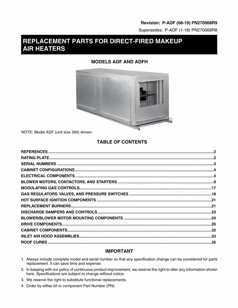
MODELS ADF AND ADFH
NOTE: Model ADF (unit size 300) shown.
TABLE OF CONTENTS
REFERENCES .........................................................................................................................................................2
RATING PLATE ........................................................................................................................................................2
SERIAL NUMBERS .................................................................................................................................................3
CABINET CONFIGURATIONS ................................................................................................................................4
ELECTRICAL COMPONENTS ................................................................................................................................4
BLOWER MOTORS, CONTACTORS, AND STARTERS .........................................................................................9
MODULATING GAS CONTROLS ..........................................................................................................................17
GAS REGULATORS, VALVES, AND PRESSURE SWITCHES ............................................................................18
HOT SURFACE IGNITION COMPONENTS ..........................................................................................................21
REPLACEMENT BURNERS ..................................................................................................................................21
DISCHARGE DAMPERS AND CONTROLS .........................................................................................................23
BLOWER/BLOWER MOTOR MOUNTING COMPONENTS .................................................................................24
DRIVE COMPONENTS ..........................................................................................................................................26
CABINET COMPONENTS .....................................................................................................................................32
INLET AIR HOOD ASSEMBLIES ..........................................................................................................................33
ROOF CURBS .......................................................................................................................................................35
2 P-ADF (08-19) PN270068R9
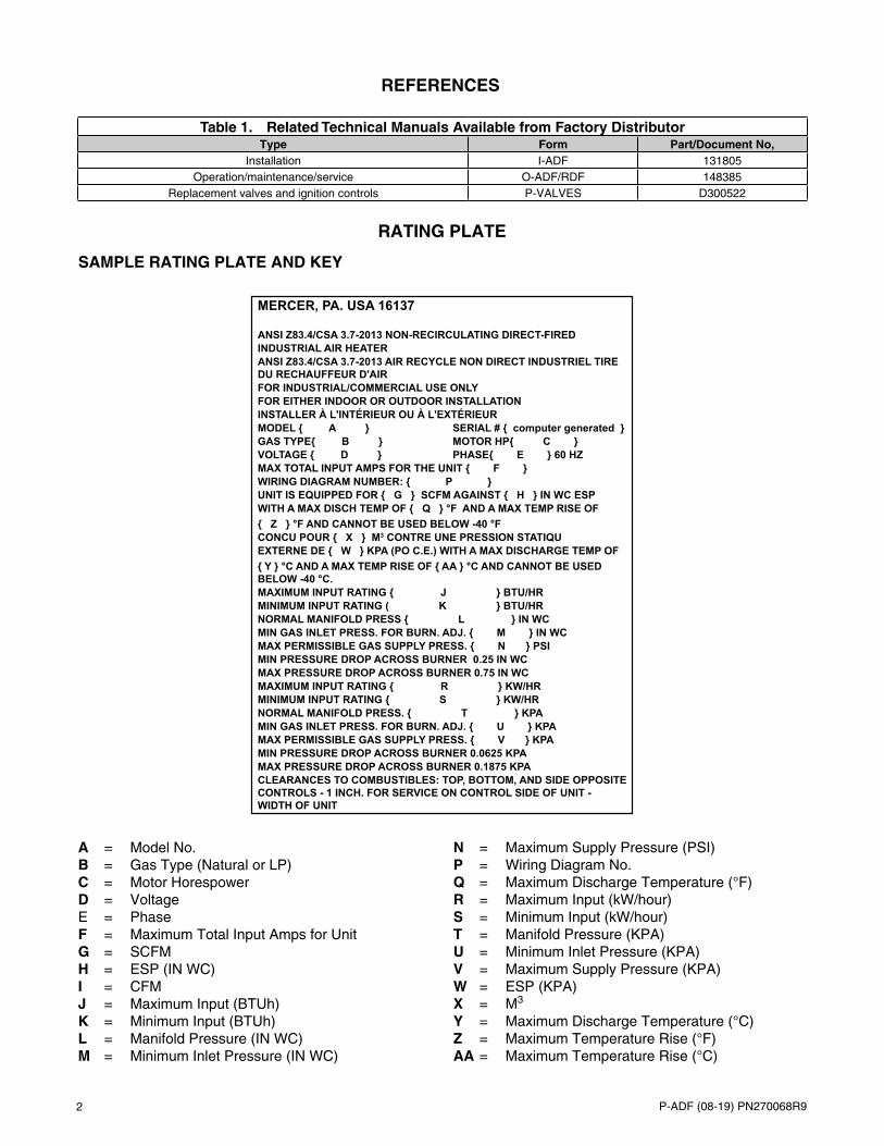
A = Model No. B = Gas Type (Natural or LP) C = Motor Horespower D = Voltage E = Phase F = Maximum Total Input Amps for Unit G = SCFM H = ESP (IN WC) I = CFM J = Maximum Input (BTUh) K = Minimum Input (BTUh) L = Manifold Pressure (IN WC) M = Minimum Inlet Pressure (IN WC)
N = Maximum Supply Pressure (PSI) P = Wiring Diagram No. Q = Maximum Discharge Temperature (°F) R = Maximum Input (kW/hour) S = Minimum Input (kW/hour) T = Manifold Pressure (KPA) U = Minimum Inlet Pressure (KPA) V = Maximum Supply Pressure (KPA) W = ESP (KPA) X = M3 Y = Maximum Discharge Temperature (°C) Z = Maximum Temperature Rise (°F) AA = Maximum Temperature Rise (°C)
REFERENCES
RATING PLATE
SAMPLE RATING PLATE AND KEY
Table 1. Related Technical Manuals Available from Factory DistributorType Form Part/Document No,
Installation I-ADF 131805Operation/maintenance/service O-ADF/RDF 148385
Replacement valves and ignition controls P-VALVES D300522
MERCER, PA. USA 16137
ANSI Z83.4/CSA 3.7-2013 NON-RECIRCULATING DIRECT-FIREDINDUSTRIAL AIR HEATERANSI Z83.4/CSA 3.7-2013 AIR RECYCLE NON DIRECT INDUSTRIEL TIRE DU RECHAUFFEUR D'AIRFOR INDUSTRIAL/COMMERCIAL USE ONLYFOR EITHER INDOOR OR OUTDOOR INSTALLATIONINSTALLER À L'INTÉRIEUR OU À L'EXTÉRIEURMODEL { A } SERIAL # { computer generated }GAS TYPE{ B } MOTOR HP{ C }VOLTAGE { D } PHASE{ E } 60 HZMAX TOTAL INPUT AMPS FOR THE UNIT { F }WIRING DIAGRAM NUMBER: { P }UNIT IS EQUIPPED FOR { G } SCFM AGAINST { H } IN WC ESPWITH A MAX DISCH TEMP OF { Q } °F AND A MAX TEMP RISE OF{ Z } °F AND CANNOT BE USED BELOW -40 °FCONCU POUR { X } M3 CONTRE UNE PRESSION STATIQUEXTERNE DE { W } KPA (PO C.E.) WITH A MAX DISCHARGE TEMP OF{ Y } °C AND A MAX TEMP RISE OF { AA } °C AND CANNOT BE USED BELOW -40 °C.MAXIMUM INPUT RATING { J } BTU/HRMINIMUM INPUT RATING ( K } BTU/HRNORMAL MANIFOLD PRESS { L } IN WCMIN GAS INLET PRESS. FOR BURN. ADJ. { M } IN WCMAX PERMISSIBLE GAS SUPPLY PRESS. { N } PSIMIN PRESSURE DROP ACROSS BURNER 0.25 IN WCMAX PRESSURE DROP ACROSS BURNER 0.75 IN WCMAXIMUM INPUT RATING { R } KW/HRMINIMUM INPUT RATING { S } KW/HRNORMAL MANIFOLD PRESS. { T } KPAMIN GAS INLET PRESS. FOR BURN. ADJ. { U } KPAMAX PERMISSIBLE GAS SUPPLY PRESS. { V } KPAMIN PRESSURE DROP ACROSS BURNER 0.0625 KPAMAX PRESSURE DROP ACROSS BURNER 0.1875 KPACLEARANCES TO COMBUSTIBLES: TOP, BOTTOM, AND SIDE OPPOSITE CONTROLS - 1 INCH. FOR SERVICE ON CONTROL SIDE OF UNIT - WIDTH OF UNIT

3P-ADF (08-19) PN270068R9
SERIAL NUMBERS
Serial number format changed in June of 2015. Use the following information to decode system serial numbers:
DECODING A SYSTEM SERIAL NUMBER FOR ALL MODELS BEFORE JUNE 2015 Serial No. Sample: BLJ 82 V1 N 00000 CA MV7 Elements of No.: 1 | 2 | 3 | 4 | 5 | 6 | 7 Key: 1 = Date code (refer to Table 2) 2 = Type of pilot 3 = Type of valve (refer to form P-Valves listed in Table 1 to identify valve by code) 4 = Type of gas (N = natural, L = propane) 5 = Consecutive number 6 = Type of air control: CA = constant air volume, VA = variable air volume, and RA = recirculation air 7 = Type of Maxitrol gas control: MV7 = system 14, MV8 = system 14A, and MVC = A200 DECODING A SYSTEM SERIAL NUMBER FOR ALL MODELS AFTER MAY 2015 Serial No. Sample: BOG 3060 000000 Elements Key No.: 1 | 2 | 3 Key: 1 = Date code (refer to Table 2) 2 = Plant of manufacture (3060 = Mercer; 3062 = Monterrey) 3 = Consecutive number
Table 2. Serial Number Date Codes (Month and Year)
YearMonth
JAN FEB MAR APR MAY JUN JUL AUG SEP OCT NOV DEC2005 BEA BEB BEC BED BEE BEF BEG BEH BEI BEJ BEK BEL2006 BFA BFB BFC BFD BFE BFF BFG BFH BFI BFJ BFK BFL2007 BGA BGB BGC BGD BGE BGF BGG BGH BGI BGJ BGK BGL2008 BHA BHB BHC BHD BHE BHF BHG BHH BHI BHJ BHK BHL2009 BIA BIB BIC BID BIE BIF BIG BIH BII BIJ BIK BIL2010 BJA BJB BJC BJD BJE BJF BJG BJH BJI BJJ BJK BJL2011 BKA BKB BKC BKD BKE BKF BKG BKH BKI BKJ BKK BKL2012 BLA BLB BLC BLD BLE BLF BLG BLH BLI BLJ BLK BLL2013 BMA BMB BMC BMD BME BMF BMG BMH BMI BMJ BMK BML2014 BNA BNB BNC BND BNE BNF BNG BNH BNI BNJ BNK BNL2015 BOA BOB BOC BOD BOE BOF BOG BOH BOI BOJ BOK BOL2016 BPA BPB BPC BPD BPE BPF BPG BPH BPI BPJ BPK BPL2017 BQA BQB BQC BQD BQE BQF BQG BQH BQI BQJ BQK BQL2018 BRA BRB BRC BRD BRE BRF BRG BRH BRI BRJ BRK BRL2019 BSA BSB BSC BSD BSE BSF BSG BSH BSI BSJ BSK BSL2020 BTA BTB BTC BTD BTE BTF BTG BTH BTI BTJ BTK BTL2021 BUA BUB BUC BUD BUE BUF BUG BUH BUI BUJ BUK BUL2022 BVA BVB BVC BVD BVE BVF BVG BVH BVI BVJ BVK BVL2023 BWA BWB BWC BWD BWE BWF BWG BWH BWI BWJ BWK BWL2024 BXA BXB BXC BXD BXE BXF BXG BXH BXI BXJ BXK BXL2025 BYA BYB BYC BYD BYE BYF BYG BYH BYI BYJ BYK BYL

4 P-ADF (08-19) PN270068R9
CABINET CONFIGURATIONS
NOTE: Unit sizes 300 and 500 have a single blower. Unit sizes 700 and 1200 have dual blowers.
Figure 1. Cabinet Configurations
ELECTRICAL COMPONENTS
Model ADF: Unit Sizes 300, 500, 700, and 1200
with Horizontal Discharge
Model ADF: Unit Sizes 300 and 500 with Vertical Discharge
Model ADFH: Unit Sizes 300, 500, 700, and 1200
with Vertical Discharge
Model ADF: Unit Sizes 700 and 1200 with Vertical Discharge
Extra cabinet is required for space to mount blower motor
Extra cabinet is required to keep motor out of airstream of higher temperature discharge air
Figure 2. Cabinet Compartments (Refer to Table 3)
Electrical Compartment
Burner/Gas Train/Electrical Compartment Motor and Blower
NOTE: Model ADF (unit size 300) shown.
5P-ADF (08-19) PN270068R9
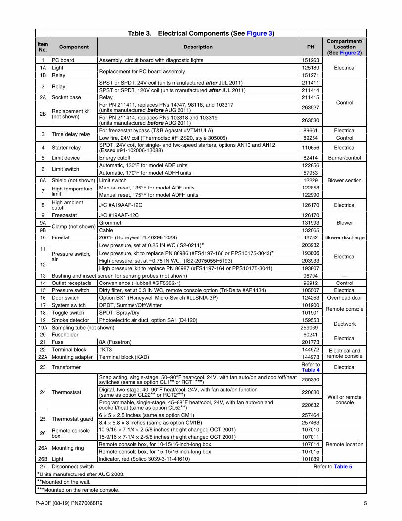
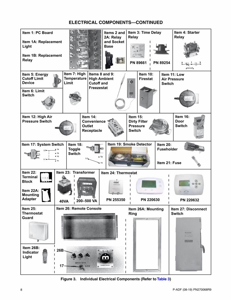
Table 3. Electrical Components (See Figure 3)
Item No. Component Description PN
Compartment/Location
(See Figure 2)1 PC board Assembly, circuit board with diagnostic lights 151263
Electrical1A LightReplacement for PC board assembly
1251891B Relay 151271
2 RelaySPST or SPDT, 24V coil (units manufactured after JUL 2011) 211411
Control
SPST or SPDT, 120V coil (units manufactured after JUL 2011) 2114142A Socket base Relay 211415
2B Replacement kit (not shown)
For PN 211411, replaces PNs 14747, 98118, and 103317 (units manufactured before AUG 2011) 263527
For PN 211414, replaces PNs 103318 and 103319 (units manufactured before AUG 2011) 263530
3 Time delay relayFor freezestat bypass (T&B Agastat #VTM1ULA) 89661 ElectricalLow fire, 24V coil (Thermodisc #F12S20, style 305005) 89254 Control
4 Starter relay SPDT, 24V coil, for single- and two-speed starters, options AN10 and AN12 (Essex #91-102006-13088) 110656 Electrical
5 Limit device Energy cutoff 82414 Burner/control
6 Limit switchAutomatic, 130°F for model ADF units 122856
Blower sectionAutomatic, 170°F for model ADFH units 57953
6A Shield (not shown) Limit switch 12229
7 High temperature limit
Manual reset, 135°F for model ADF units 122858Manual reset, 175°F for model ADFH units 122990
8 High ambient cutoff J/C #A19AAF-12C 126170 Electrical
9 Freezestat J/C #19AAF-12C 126170Blower9A
Clamp (not shown)Grommet 131993
9B Cable 13206510 Firestat 200°F (Honeywell #L4029E1029) 42782 Blower discharge
11Pressure switch, air
Low pressure, set at 0.25 IN WC (IS2-0211)* 203932
ElectricalLow pressure, kit to replace PN 86986 (#FS4197-166 or PPS10175-3043)* 193806
12High pressure, set at −0.75 IN WC, (IS2-2075055F5193) 203933High pressure, kit to replace PN 86987 (#FS4197-164 or PPS10175-3041) 193807
13 Bushing and insect screen for sensing probes (not shown) 96794 —14 Outlet receptacle Convenience (Hubbell #GF5352-1) 96912 Control15 Pressure switch Dirty filter, set at 0.3 IN WC, remote console option (Tri-Delta #AP4434) 105507 Electrical16 Door switch Option BX1 (Honeywell Micro-Switch #LLSNIA-3P) 124253 Overhead door17 System switch DPDT, Summer/Off/Winter 101900
Remote console18 Toggle switch SPDT, Spray/Dry 10190119 Smoke detector Photoelectric air duct, option SA1 (D4120) 159553
Ductwork19A Sampling tube (not shown) 25906920 Fuseholder 60241
Electrical21 Fuse 8A (Fusetron) 20177322 Terminal block #KT3 144972 Electrical and
remote console22A Mounting adapter Terminal block (KAD) 144973
23 Transformer Refer to Table 4 Electrical
24 Thermostsat
Snap acting, single-stage, 50–90°F heat/cool, 24V, with fan auto/on and cool/off/heat switches (same as option CL1** or RCT1***) 255350
Wall or remote console
Digital, two-stage, 40–90°F heat/cool, 24V, with fan auto/on function (same as option CL22** or RCT2***) 220630
Programmable, single-stage, 45–88°F heat/cool, 24V, with fan auto/on and cool/off/heat (same as option CL52**) 220632
25 Thermostat guard6 × 5 × 2.5 inches (same as option CM1) 2574648.4 × 5.8 × 3 inches (same as option CM1B) 257463
26 Remote console box
10-9/16 × 7-1/4 × 2-5/8 inches (height changed OCT 2001) 107010
Remote location15-9/16 × 7-1/4 × 2-5/8 inches (height changed OCT 2001) 107011
26A Mounting ringRemote console box, for 10-15/16-inch-long box 107014Remote console box, for 15-15/16-inch-long box 107015
26B Light Indicator, red (Solico 3039-3-11-41610) 10188927 Disconnect switch Refer to Table 5
*Units manufactured after AUG 2003.
**Mounted on the wall.
***Mounted on the remote console.
6 P-ADF (08-19) PN270068R9
ELECTRICAL COMPONENTS—CONTINUED
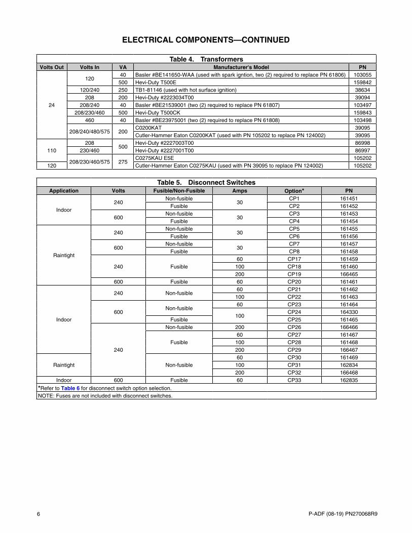
Table 4. TransformersVolts Out Volts In VA Manufacturer's Model PN
24
12040 Basler #BE141650-WAA (used with spark igntion, two (2) required to replace PN 61806) 103055500 Hevi-Duty T500E 159842
120/240 250 TB1-81146 (used with hot surface ignition) 38634208 200 Hevi-Duty #2223034T00 39094
208/240 40 Basler #BE21539001 (two (2) required to replace PN 61807) 103497208/230/460 500 Hevi-Duty T500CK 159843
460 40 Basler #BE23975001 (two (2) required to replace PN 61808) 103498
208/240/480/575 200C0200KAT 39095Cutler-Hammer Eaton C0200KAT (used with PN 105202 to replace PN 124002) 39095
110208
500Hevi-Duty #2227003T00 86998
230/460 Hevi-Duty #2227001T00 86997
208/230/460/575 275C0275KAU E5E 105202
120 Cutler-Hammer Eaton C0275KAU (used with PN 39095 to replace PN 124002) 105202
Table 5. Disconnect SwitchesApplication Volts Fusible/Non-Fusible Amps Option* PN
Indoor240
Non-fusible30
CP1 161451Fusible CP2 161452
600Non-fusible
30CP3 161453
Fusible CP4 161454
Raintight
240Non-fusible
30CP5 161455
Fusible CP6 161456
600Non-fusible
30CP7 161457
Fusible CP8 161458
240 Fusible60 CP17 161459100 CP18 161460200 CP19 166465
600 Fusible 60 CP20 161461
Indoor
240 Non-fusible60 CP21 161462100 CP22 161463
600Non-fusible
60 CP23 161464
100CP24 164330
Fusible CP25 161465
240
Non-fusible 200 CP26 166466
Fusible60 CP27 161467100 CP28 161468200 CP29 166467
Raintight Non-fusible60 CP30 161469100 CP31 162834200 CP32 166468
Indoor 600 Fusible 60 CP33 162835
*Refer to Table 6 for disconnect switch option selection.NOTE: Fuses are not included with disconnect switches.

7P-ADF (08-19) PN270068R9
Table 6. Disconnect Switch Option (CP) Selection
HP FLA (Approximate
V/PH115/1 208/1 or 230/1 208/3 or 230/3 460/3 or 575/3
CP Option
1/4
9.3 CP1/CP2/CP5/CP6 —4.7 — CP1/CP2/CP5/CP6 —3.8 — CP1/CP2/CP5/CP6 —1.85 — CP3/CP4/CP7/CP8
1/3
9.7 CP1/CP2/CP5/CP6 —5.6 — CP1/CP2/CP5/CP6 —4 — CP1/CP2/CP5/CP6 —
1.9 — CP1/CP2/CP5/CP6
1/2
13.0 CP1/CP2/CP5/CP6 —7.5 — CP1/CP2/CP5/CP6 —4.5 — CP1/CP2/CP5/CP6 —2.1 — CP3/CP4/CP7/CP8
3/4
15.2 CP1/CP2/CP5/CP6 —8.7 — CP1/CP2/CP5/CP6 —5.3 — CP1/CP2/CP5/CP6 —2.4 — CP3/CP4/CP7/CP8
1
17.2 CP1/CP2/CP5/CP6 —9.9 — CP1/CP2/CP5/CP6 —6.1 — CP1/CP2/CP5/CP6 —2.5 — CP3/CP4/CP7/CP8
1-1/2
19.2 CP1/CP2/CP5/CP6 —10.7 — CP1/CP2/CP5/CP6 —8.0 — CP1/CP2/CP5/CP6 —3.8 — CP3/CP4/CP7/CP8
2
24.6 CP1/CP2/CP5/CP6 —12.6 — CP1/CP2/CP5/CP6 —9.4 — CP1/CP2/CP5/CP6 —4.4 — CP3/CP4/CP7/CP8
314.8 — CP1/CP2/CP5/CP6 —11.5 — CP1/CP2/CP5/CP6 —5.3 — CP3/CP4/CP7/CP8
530.4 — CP17/CP21/CP27/CP30 —15.9 — CP1/CP2/CP5/CP6 —7.7 — CP3/CP4/CP7/CP8
7-1/240.4 — CP17/CP21/CP27/CP30 —24.4 — CP1/CP2/CP5/CP6 —11.6 — CP3/CP4/CP7/CP8
1044.4 — CP17/CP21/CP27/CP30 —32.4 — CP17/CP21/CP27/CP30 —14.1 — CP3/CP4/CP7/CP8
1545.5 — CP17/CP21/CP27/CP30 —20.6 — CP3/CP4/CP7/CP8
2061.4 — CP18/CP22/CP28/CP31 —27.6 — CP3/CP4/CP7/CP8
8 P-ADF (08-19) PN270068R9
ELECTRICAL COMPONENTS—CONTINUED
Figure 3. Individual Electrical Components (Refer to Table 3)
Items 2 and 2A: Relay and Socket Base
PN 89661
Item 1: PC Board Item 1A: Replacement Light Item 1B: Replacement Relay
Item 7: High Temperature Limit
Items 8 and 9: High Ambient
Freezestat
Item 4: Starter Relay
Item 6: Limit Switch
Item 22: Terminal Block Item 22A: Mounting Adapter
Item 20: Fuseholder
Item 21: Fuse
Item 17: System Switch
Item 16: Door Switch
Item 18: Toggle Switch
Item 19: Smoke Detector
Item 15: Dirty Filter Pressure Switch
Item 14: Convenience Outlet Receptacle
Item 23: Transformer
Item 10: Firestat
Item 11: Low Air Pressure Switch
Item 12: High Air Pressure Switch
Item 5: Energy
Device
40VA 200–500 VA
Item 3: Time Delay Relay
PN 89254
Item 24: Thermostat
PN 255350 PN 220630 PN 220632
Item 27: Disconnect Switch
Item 26: Remote ConsoleItem 25: Thermostat Guard
Item 26B: Indicator Light
Item 26A: Mounting Ring
17
26B
9P-ADF (08-19) PN270068R9
BLOWER MOTORS, CONTACTORS, AND STARTERS
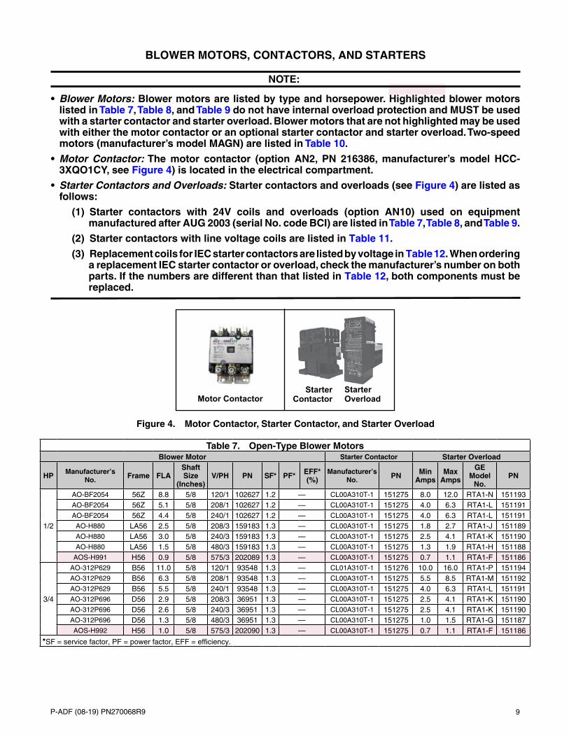
NOTE:
• Blower Motors: Blower motors are listed by type and horsepower. Highlighted blower motors listed in Table 7, Table 8, and Table 9 do not have internal overload protection and MUST be used with a starter contactor and starter overload. Blower motors that are not highlighted may be used with either the motor contactor or an optional starter contactor and starter overload. Two-speed motors (manufacturer’s model MAGN) are listed in Table 10.
• Motor Contactor: The motor contactor (option AN2, PN 216386, manufacturer’s model HCC-3XQO1CY, see Figure 4) is located in the electrical compartment.
• Starter Contactors and Overloads: Starter contactors and overloads (see Figure 4) are listed as follows:
(1) Starter contactors with 24V coils and overloads (option AN10) used on equipment manufactured after AUG 2003 (serial No. code BCI) are listed in Table 7, Table 8, and Table 9.
(2) Starter contactors with line voltage coils are listed in Table 11.
(3) Replacement coils for IEC starter contactors are listed by voltage in Table 12. When ordering a replacement IEC starter contactor or overload, check the manufacturer’s number on both parts. If the numbers are different than that listed in Table 12, both components must be replaced.
Starter OverloadMotor Contactor
Starter Contactor
Figure 4. Motor Contactor, Starter Contactor, and Starter Overload
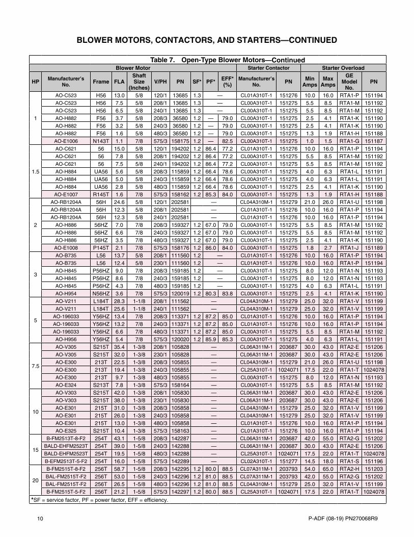
Table 7. Open-Type Blower MotorsBlower Motor Starter Contactor Starter Overload
HP Manufacturer’s No. Frame FLA
Shaft Size
(Inches)V/PH PN SF* PF* EFF*
(%)Manufacturer’s
No. PN Min Amps
Max Amps
GE Model
No.PN
1/2
AO-BF2054 56Z 8.8 5/8 120/1 102627 1.2 — CL00A310T-1 151275 8.0 12.0 RTA1-N 151193AO-BF2054 56Z 5.1 5/8 208/1 102627 1.2 — CL00A310T-1 151275 4.0 6.3 RTA1-L 151191AO-BF2054 56Z 4.4 5/8 240/1 102627 1.2 — CL00A310T-1 151275 4.0 6.3 RTA1-L 151191AO-H880 LA56 2.5 5/8 208/3 159183 1.3 — CL00A310T-1 151275 1.8 2.7 RTA1-J 151189AO-H880 LA56 3.0 5/8 240/3 159183 1.3 — CL00A310T-1 151275 2.5 4.1 RTA1-K 151190AO-H880 LA56 1.5 5/8 480/3 159183 1.3 — CL00A310T-1 151275 1.3 1.9 RTA1-H 151188
AOS-H991 H56 0.9 5/8 575/3 202089 1.3 — CL00A310T-1 151275 0.7 1.1 RTA1-F 151186
3/4
AO-312P629 B56 11.0 5/8 120/1 93548 1.3 — CL01A310T-1 151276 10.0 16.0 RTA1-P 151194AO-312P629 B56 6.3 5/8 208/1 93548 1.3 — CL00A310T-1 151275 5.5 8.5 RTA1-M 151192AO-312P629 B56 5.5 5/8 240/1 93548 1.3 — CL00A310T-1 151275 4.0 6.3 RTA1-L 151191AO-312P696 D56 2.9 5/8 208/3 36951 1.3 — CL00A310T-1 151275 2.5 4.1 RTA1-K 151190AO-312P696 D56 2.6 5/8 240/3 36951 1.3 — CL00A310T-1 151275 2.5 4.1 RTA1-K 151190AO-312P696 D56 1.3 5/8 480/3 36951 1.3 — CL00A310T-1 151275 1.0 1.5 RTA1-G 151187AOS-H992 H56 1.0 5/8 575/3 202090 1.3 — CL00A310T-1 151275 0.7 1.1 RTA1-F 151186
*SF = service factor, PF = power factor, EFF = efficiency.
10 P-ADF (08-19) PN270068R9
Table 7. Open-Type Blower MotorsBlower Motor Starter Contactor Starter Overload
HP Manufacturer’s No. Frame FLA
Shaft Size
(Inches)V/PH PN SF* PF* EFF*
(%)Manufacturer’s
No. PN Min Amps
Max Amps
GE Model
No.PN
1
AO-C523 H56 13.0 5/8 120/1 13685 1.3 — CL01A310T-1 151276 10.0 16.0 RTA1-P 151194AO-C523 H56 7.5 5/8 208/1 13685 1.3 — CL00A310T-1 151275 5.5 8.5 RTA1-M 151192AO-C523 H56 6.5 5/8 240/1 13685 1.3 — CL00A310T-1 151275 5.5 8.5 RTA1-M 151192AO-H882 F56 3.7 5/8 208/3 36580 1.2 — 79.0 CL00A310T-1 151275 2.5 4.1 RTA1-K 151190AO-H882 F56 3.2 5/8 240/3 36580 1.2 — 79.0 CL00A310T-1 151275 2.5 4.1 RTA1-K 151190AO-H882 F56 1.6 5/8 480/3 36580 1.2 — 79.0 CL00A310T-1 151275 1.3 1.9 RTA1-H 151188AO-E1006 N143T 1.1 7/8 575/3 158175 1.2 — 82.5 CL00A310T-1 151275 1.0 1.5 RTA1-G 151187
1.5
AO-C621 56 15.0 5/8 120/1 194202 1.2 86.4 77.2 CL01A310T-1 151276 10.0 16.0 RTA1-P 151194AO-C621 56 7.8 5/8 208/1 194202 1.2 86.4 77.2 CL00A310T-1 151275 5.5 8.5 RTA1-M 151192AO-C621 56 7.5 5/8 240/1 194202 1.2 86.4 77.2 CL00A310T-1 151275 5.5 8.5 RTA1-M 151192AO-H884 UA56 5.6 5/8 208/3 115859 1.2 66.4 78.6 CL00A310T-1 151275 4.0 6.3 RTA1-L 151191AO-H884 UA56 5.0 5/8 240/3 115859 1.2 66.4 78.6 CL00A310T-1 151275 4.0 6.3 RTA1-L 151191AO-H884 UA56 2.8 5/8 480/3 115859 1.2 66.4 78.6 CL00A310T-1 151275 2.5 4.1 RTA1-K 151190AO-E1007 R145T 1.6 7/8 575/3 158162 1.2 85.3 84.0 CL00A310T-1 151275 1.3 1.9 RTA1-H 151188
2
AO-RB1204A 56H 24.6 5/8 120/1 202581 — CL04A310M-1 151279 21.0 26.0 RTA1-U 151198AO-RB1204A 56H 12.3 5/8 208/1 202581 — CL01A310T-1 151276 10.0 16.0 RTA1-P 151194AO-RB1204A 56H 12.3 5/8 240/1 202581 — CL01A310T-1 151276 10.0 16.0 RTA1-P 151194
AO-H886 56HZ 7.0 7/8 208/3 159327 1.2 67.0 79.0 CL00A310T-1 151275 5.5 8.5 RTA1-M 151192AO-H886 56HZ 6.6 7/8 240/3 159327 1.2 67.0 79.0 CL00A310T-1 151275 5.5 8.5 RTA1-M 151192AO-H886 56HZ 3.5 7/8 480/3 159327 1.2 67.0 79.0 CL00A310T-1 151275 2.5 4.1 RTA1-K 151190AO-E1008 P145T 2.1 7/8 575/3 158176 1.2 86.0 84.0 CL00A310T-1 151275 1.8 2.7 RTA1-J 151189
3
AO-B735 L56 13.7 5/8 208/1 111560 1.2 — CL01A310T-1 151276 10.0 16.0 RTA1-P 151194AO-B735 L56 12.4 5/8 230/1 111560 1.2 — CL01A310T-1 151276 10.0 16.0 RTA1-P 151194AO-H845 P56HZ 9.0 7/8 208/3 159185 1.2 — CL00A310T-1 151275 8.0 12.0 RTA1-N 151193AO-H845 P56HZ 8.6 7/8 240/3 159185 1.2 — CL00A310T-1 151275 8.0 12.0 RTA1-N 151193AO-H845 P56HZ 4.3 7/8 480/3 159185 1.2 — CL00A310T-1 151275 4.0 6.3 RTA1-L 151191AO-H954 N56HZ 3.6 7/8 575/3 120019 1.2 80.3 83.8 CL00A310T-1 151275 2.5 4.1 RTA1-K 151190
5
AO-V211 L184T 28.3 1-1/8 208/1 111562 — CL04A310M-1 151279 25.0 32.0 RTA1-V 151199AO-V211 L184T 25.6 1-1/8 240/1 111562 — CL04A310M-1 151279 25.0 32.0 RTA1-V 151199
AO-196033 Y56HZ 13.4 7/8 208/3 113371 1.2 87.2 85.0 CL01A310T-1 151276 10.0 16.0 RTA1-P 151194AO-196033 Y56HZ 13.2 7/8 240/3 113371 1.2 87.2 85.0 CL01A310T-1 151276 10.0 16.0 RTA1-P 151194AO-196033 Y56HZ 6.6 7/8 480/3 113371 1.2 87.2 85.0 CL00A310T-1 151275 5.5 8.5 RTA1-M 151192AO-H956 Y56HZ 5.4 7/8 575/3 120020 1.2 85.9 85.3 CL00A310T-1 151275 4.0 6.3 RTA1-L 151191
7.5
AO-V305 S215T 35.4 1-3/8 208/1 105828 — CL06A311M-1 203687 30.0 43.0 RTA2-E 151206AO-V305 S215T 32.0 1-3/8 230/1 105828 — CL06A311M-1 203687 30.0 43.0 RTA2-E 151206AO-E300 213T 22.5 1-3/8 208/3 105855 — CL04A310M-1 151279 21.0 26.0 RTA1-U 151198AO-E300 213T 19.4 1-3/8 240/3 105855 — CL25A310T-1 1024071 17.5 22.0 RTA1-T 1024078AO-E300 213T 9.7 1-3/8 480/3 105855 — CL00A310T-1 151275 8.0 12.0 RTA1-N 151193AO-E324 S213T 7.8 1-3/8 575/3 158164 — CL00A310T-1 151275 5.5 8.5 RTA1-M 151192
10
AO-V303 S215T 42.0 1-3/8 208/1 105830 — CL06A311M-1 203687 30.0 43.0 RTA2-E 151206AO-V303 S215T 38.0 1-3/8 230/1 105830 — CL06A311M-1 203687 30.0 43.0 RTA2-E 151206AO-E301 215T 31.0 1-3/8 208/3 105858 — CL04A310M-1 151279 25.0 32.0 RTA1-V 151199AO-E301 215T 26.0 1-3/8 240/3 105858 — CL04A310M-1 151279 25.0 32.0 RTA1-V 151199AO-E301 215T 13.0 1-3/8 480/3 105858 — CL01A310T-1 151276 10.0 16.0 RTA1-P 151194AO-E325 S215T 10.4 1-3/8 575/3 158163 — CL01A310T-1 151276 10.0 16.0 RTA1-P 151194
15
B-FM2513T-8-F2 254T 43.1 1-5/8 208/3 142287 — CL06A311M-1 203687 42.0 55.0 RTA2-G 151202BALD-EHFM2523T 254T 39.0 1-5/8 240/3 142288 — CL06A311M-1 203687 30.0 43.0 RTA2-E 151206BALD-EHFM2523T 254T 19.5 1-5/8 480/3 142288 — CL25A310T-1 1024071 17.5 22.0 RTA1-T 1024078B-EFM2513T-5-F2 254T 16.0 1-5/8 575/3 142289 — CL02A310T-1 151277 14.5 18.0 RTA1-S 151196
20
B-FM2515T-8-F2 256T 58.7 1-5/8 208/3 142295 1.2 80.0 88.5 CL07A311M-1 203793 54.0 65.0 RTA2-H 151203BAL-FM2515T-F2 256T 53.0 1-5/8 240/3 142296 1.2 81.0 88.5 CL07A311M-1 203793 42.0 55.0 RTA2-G 151202BAL-FM2515T-F2 256T 26.5 1-5/8 480/3 142296 1.2 81.0 88.5 CL04A310M-1 151279 25.0 32.0 RTA1-V 151199B-FM2515T-5-F2 256T 21.2 1-5/8 575/3 142297 1.2 80.0 88.5 CL25A310T-1 1024071 17.5 22.0 RTA1-T 1024078
*SF = service factor, PF = power factor, EFF = efficiency.
BLOWER MOTORS, CONTACTORS, AND STARTERS—CONTINUED
—Continued

11P-ADF (08-19) PN270068R9
Table 8. TEFC-Type Blower MotorsBlower Motor Starter Contactor Starter Overload
HP Manufacturer’s No. Frame FLA
Shaft Size
(Inches)V/PH PN SF* PF* EFF*
(%)Manufacturer’s
No. PN Min Amps
Max Amps
GE Model
No.PN
1/2
AO-C613 J56 7.2 5/8 120/1 159184 — CL00A310T-1 151275 5.5 8.5 RTA1-M 151192AO-C613 J56 3.5 5/8 208/1 159184 — CL00A310T-1 151275 2.5 4.1 RTA1-K 151190AO-C613 J56 3.6 5/8 240/1 159184 — CL00A310T-1 151275 2.5 4.1 RTA1-K 151190AO-H274 H56 2.3 5/8 208/3 16077 1.0 59.5 74.8 CL00A310T-1 151275 1.8 2.7 RTA1-J 151189AO-H274 H56 2.0 5/8 240/3 16077 1.0 59.5 74.8 CL00A310T-1 151275 1.8 2.7 RTA1-J 151189AO-H274 H56 1.0 5/8 480/3 16077 1.0 59.5 74.8 CL00A310T-1 151275 0.7 1.1 RTA1-F 151186AO-H276 J56 0.7 5/8 575/3 105568 1.2 76.4 77.0 CL00A310T-1 151275 0.7 1.1 RTA1-F 151186
3/4
AO-F353 F56 11.0 5/8 120/1 115860 — CL01A310T-1 151276 10.0 16.0 RTA1-P 151194AO-F353 F56 5.4 5/8 208/1 115860 — CL00A310T-1 151275 4.0 6.3 RTA1-L 151191AO-F353 F56 5.5 5/8 240/1 159184 — CL00A310T-1 151275 4.0 6.3 RTA1-L 151191AO-H580 KA56 2.0 5/8 208/3 20371 1.0 73.5 81.1 CL00A310T-1 151275 1.8 2.7 RTA1-J 151189AO-H580 KA56 2.2 5/8 240/3 20371 1.0 73.5 81.1 CL00A310T-1 151275 1.8 2.7 RTA1-J 151189AO-H580 KA56 1.1 5/8 480/3 20371 1.0 73.5 81.1 CL00A310T-1 151275 1.0 1.5 RTA1-G 151187AO-H461 L56 0.8 5/8 575/3 105569 1.2 78.3 82.0 CL00A310T-1 151275 0.7 1.1 RTA1-F 151186
1
AO-159105 L56 12.0 5/8 120/1 174993 — CL01A310T-1 151276 10.0 16.0 RTA1-P 151194AO-159105 L56 6.2 5/8 208/1 174993 — CL00A310T-1 151275 4.0 6.3 RTA1-L 151191AO-159105 L56 6.0 5/8 240/1 174993 — CL00A310T-1 151275 4.0 6.3 RTA1-L 151191AO-H524 J56 3.3 5/8 208/3 16080 1.0 74.4 80.2 CL00A310T-1 151275 2.5 4.1 RTA1-K 151190AO-H524 J56 3.4 5/8 240/3 16080 1.0 74.4 80.2 CL00A310T-1 151275 2.5 4.1 RTA1-K 151190AO-H524 J56 1.7 5/8 480/3 16080 1.0 74.4 80.2 CL00A310T-1 151275 1.3 1.9 RTA1-K 151188AO-H525 H56 1.4 5/8 575/3 105570 1.2 71.6 80.4 CL00A310T-1 151275 1.0 1.5 RTA1-H 151187
1.5
AO-311P402 TK56H 16.4 5/8 120/1 94347 — CL02A310T-1 151277 14.5 18.0 RTA1-S 151196AO-311P402 TK56H 9.5 5/8 208/1 94347 — CL00A310T-1 151275 8.0 12.0 RTA1-N 151193AO-311P402 TK56H 8.2 5/8 240/1 94347 — CL00A310T-1 151275 8.0 12.0 RTA1-N 151193
AO-H535 L56H 4.3 5/8 208/3 101286 1.0 80.9 82.4 CL00A310T-1 151275 4.0 6.3 RTA1-L 151191AO-H535 L56H 4.4 5/8 240/3 101286 1.0 80.9 82.4 CL00A310T-1 151275 4.0 6.3 RTA1-L 151191AO-H535 L56H 2.2 5/8 480/3 101286 1.0 80.9 82.4 CL00A310T-1 151275 1.8 2.7 RTA1-J 151189AO-E127 M145T 1.6 7/8" 575/3 105665 1.2 85.7 84.0 CL00A310T-1 151275 1.3 1.9 RTA1-H 151188
2
AO-K200 F182T 24.0 1-1/8 120/1 105572 — CL04A310M-1 151279 21.0 26.0 RTA1-U 151198L3516TM 56HZ 8.3 7/8 240/1 205881 1.2 99.0 78.0 CL00A310T-1 151275 5.5 8.5 RTA1-M 151192AO-E166 145T 7.0 7/8 208/3 158165 — CL00A310T-1 151275 5.5 8.5 RTA1-M 151192AO-E166 145T 5.8 7/8 240/3 158165 — CL00A310T-1 151275 4.0 6.3 RTA1-L 151191AO-E166 145T 2.9 7/8 480/3 158165 — CL00A310T-1 151275 2.5 4.1 RTA1-K 151190AO-E169 145T 2.3 7/8 575/3 158166 — CL00A310T-1 151275 1.9 2.7 RTA1-J 151189
3
AO-K222 F184T 30.0 1-1/8 120/1 111564 — CL04A310M-1 151279 25.0 32.0 RTA1-V 151199AO-K222 F184T 15.0 1-1/8 240/1 111564 — CL02A310T-1 151277 14.5 18.0 RTA1-S 151196
B - M3559T 145T 7.9 7/8 208/3 159330 — CL00A310T-1 151275 5.5 8.5 RTA1-M 151192B - M3559T 145T 7.2 7/8 240/3 159330 — CL00A310T-1 151275 5.5 8.5 RTA1-M 151192B - M3559T 145T 3.6 7/8 480/3 159330 — CL00A310T-1 151275 2.5 4.1 RTA1-K 151190B-M3559T-5 145T 3.0 7/8 575/3 111571 — CL00A310T-1 151275 2.5 4.1 RTA1-K 151190
5
AO-K223 F184T 20.2 1-1/8 240/1 111567 — CL25A310T-1 1024071 17.5 22.0 RTA1-T 1024078AO-E241 184T 16.0 1-1/8 208/3 155048 — CL02A310T-1 151277 14.5 18.0 RTA1-S 151196AO-E241 184T 12.0 1-1/8 240/3 155048 — CL01A310T-1 151276 10.0 16.0 RTA1-P 151194AO-E241 184T 6.0 1-1/8 480/3 155048 — CL00A310T-1 151275 4.0 6.3 RTA1-L 151191AO-E273 184T 4.8 1-1/8 575/3 158170 — CL00A310T-1 151275 4.0 6.3 RTA1-L 151191
7.5
AO-K305 F215T 34.0 1-3/8 240/1 105842 — CL06A311M-1 203687 30.0 43.0 RTA2-E 151206AO-E356 213T 24.0 1-3/8 208/3 158171 — CL04A310M-1 151279 21.0 26.0 RTA1-U 151198AO-E356 213T 19.0 1-3/8 240/3 158171 — CL25A310T-1 1024071 17.5 22.0 RTA1-T 1024078AO-E356 213T 9.5 1-3/8 480/3 158171 — CL00A310T-1 151275 8.0 12.0 RTA1-N 151193AO-E364 213T 7.6 1-3/8 575/3 158172 — CL00A310T-1 151275 5.5 8.5 RTA1-M 151192
10
AO-K313 215T 39.0 1-3/8 240/1 105846 — CL06A311M-1 203687 30.0 43.0 RTA2-E 151206AO-E357 215T 30.0 1-3/8 208/3 158173 — CL04A310M-1 151279 25.0 32.0 RTA1-V 151199AO-E357 215T 26.0 1-3/8 240/3 158173 — CL04A310M-1 151279 21.0 26.0 RTA1-U 151198AO-E357 215T 13.0 1-3/8 480/3 158173 — CL02A310T-1 151277 10.0 16.0 RTA1-P 151194AO-E365 215T 9.6 1-3/8 575/3 158174 — CL00A310T-1 151275 8.0 12.0 RTA1-N 151193
*SF = service factor, PF = power factor, EFF = efficiency.

12 P-ADF (08-19) PN270068R9
Table 8. TEFC-Type Blower MotorsBlower Motor Starter Contactor Starter Overload
HP Manufacturer’s No. Frame FLA
Shaft Size
(Inches)V/PH PN SF* PF* EFF*
(%)Manufacturer’s
No. PN Min Amps
Max Amps
GE Model
No.PN
15BAL-FM2333T 254T 38.0 1-5/8 240/3 142443 1.2 82.0 90.2 CL06A311M-1 203687 30.0 43.0 RTA2-E 151206BAL-FM2333T 254T 19.0 1-5/8 480/3 142443 1.2 82.0 90.2 CL25A310T-1 1024071 17.5 22.0 RTA1-T 1024078B-FM2333-5 254T 15.0 1-5/8 575/3 142444 1.2 82.0 90.2 CL02A310T-1 151277 10.0 16.0 RTA1-P 151194
20BAL-FM2334T 256T 52.0 1-5/8 240/3 142301 1.2 81.0 89.5 CL07A311M-1 203793 42.0 55.0 RTA2-G 151202BAL-FM2334T 256T 26.0 1-5/8 480/3 142301 1.2 81.0 89.5 CL04A310M-1 151279 25.0 32.0 RTA1-V 151199B-FM2334T-5 256T 20.6 1-5/8 575/3 142302 1.2 81.0 89.5 CL25A310T-1 1024071 17.5 22.0 RTA1-T 1024078
*SF = service factor, PF = power factor, EFF = efficiency.
BLOWER MOTORS, CONTACTORS, AND STARTERS—CONTINUED
—Continued
Table 9. EE-Type (Premium Efficiency) Blower MotorsBlower Motor Starter Contactor Starter Overload
HP Manufacturer’s No. Frame FLA
Shaft Size
(Inches)V/PH PN SF* PF* EFF*
(%)Manufacturer’s
No. PN Min Amps
Max Amps
GE Model
No.PN
1
AO-E103 N143T 3.1 7/8 208/3 105659 — CL00A310T-1 151275 2.5 4.1 RTA1-K 151190AO-E1015 143T 2.7 7/8 240/3 159328 — CL00A310T-1 151275 2.5 4.1 RTA1-K 151190AO-E1015 143T 1.4 7/8 480/3 159328 — CL00A310T-1 151275 1.0 1.5 RTA1-G 151187AO-E1006 N143T 1.1 7/8 575/3 158175 — CL00A310T-1 151275 1.0 1.5 RTA1-G 151187
1.5
AO-E104 P145T 4.5 7/8 208/3 105662 — CL00A310T-1 151275 4.0 6.3 RTA1-L 151191AO-E1016 145T 3.9 7/8 240/3 159329 — CL00A310T-1 151275 2.5 4.1 RTA1-K 151190AO-E1016 145T 2.0 7/8 480/3 159329 — CL00A310T-1 151275 1.9 2.7 RTA1-J 151189AO-E1007 R145T 1.6 7/8 575/3 158162 — CL00A310T-1 151275 1.3 1.9 RTA1-H 151188
2
AO-E105 P145T 6.0 7/8 208/3 105664 — CL00A310T-1 151275 4.0 6.3 RTA1-L 151191AO-E1017 145T 5.8 7/8 240/3 159027 — CL00A310T-1 151275 4.0 6.3 RTA1-L 151191AO-E1017 145T 2.9 7/8 480/3 159027 — CL00A310T-1 151275 2.5 4.1 RTA1-K 151190AO-E1008 P145T 2.1 7/8 575/3 158176 — CL00A310T-1 151275 1.9 2.7 RTA1-J 151189
3
B-35L405S489G3 145T 8.3 7/8 208/3 159186 — CL00A310T-1 151275 8.0 12.0 RTA1-N 151193B-EM3158T 145T 7.4 7/8 240/3 159028 — CL00A310T-1 151275 5.5 8.5 RTA1-M 151192B-EM3158T 145T 3.7 7/8 480/3 159028 — CL00A310T-1 151275 2.5 4.1 RTA1-K 151190
B-35L405S709G1 145T 3.0 7/8 575/3 159030 — CL00A310T-1 151275 2.5 4.1 RTA1-K 151190
5
AO-E204 H182T 13.9 1-1/8 208/3 159029 — CL02A310T-1 151277 10.0 16.0 RTA1-P 151194AO-E204 H182T 11.6 1-1/8 240/3 159029 — CL01A310T-1 151276 10.0 16.0 RTA1-P 151194AO-E204 H182T 5.8 1-1/8 480/3 159029 — CL00A310T-1 151275 5.5 8.5 RTA1-M 151192
BAL-M3613T-5 184T 4.8 1-1/8 575/3 111602 — CL00A310T-1 151275 4.0 6.3 RTA1-L 151191
7.5
AO-E316 D213T 22.3 1-3/8 208/3 159331 — CL04A310M-1 151279 21.0 26.0 RTA1-U 151198AO-E317 D213T 19.4 1-3/8 240/3 159332 — CL25A310T-1 1024071 17.5 22.0 RTA1-T 1024078AO-E317 D213T 9.7 1-3/8 480/3 159332 — CL00A310T-1 151275 8.0 12.0 RTA1-N 151193AO-E324 S213T 7.8 1-3/8 575/3 158164 — CL00A310T-1 151275 5.5 8.5 RTA1-M 151192
10
AO-E397 H215T 27.8 1-3/8 208/3 159334 — CL04A310M-1 151279 25.0 32.0 RTA1-V 151199AO-E397 H215T 24.2 1-3/8 240/3 159334 — CL04A310M-1 151279 21.0 26.0 RTA1-U 151198AO-E397 H215T 12.1 1-3/8 480/3 159334 — CL01A310T-1 151276 10.0 16.0 RTA1-P 151194AO-E325 S215T 10.4 1-3/8 575/3 158163 — CL01A310T-1 151276 10.0 16.0 RTA1-P 151194
15
B-EFM2513T-8 254T 41.5 1-5/8 208/3 142440 1.2 84.0 92.4 CL06A311M-1 203687 30.0 43.0 RTA2-E 151206B-EFM2513T 254T 36.0 1-5/8 240/3 142441 1.2 84.0 92.4 CL06A311M-1 203687 30.0 43.0 RTA2-E 151206B-EFM2513T 254T 18.0 1-5/8 480/3 142441 1.2 84.0 92.4 CL25A310T-1 1024071 17.5 22.0 RTA1-T 1024078
B-EFM2513T-5-F2 254T 16.0 1-5/8 575/3 142289 1.2 84.0 92.4 CL02A310T-1 151277 10.0 16.0 RTA1-P 151194
20
C-E452-F2 S256T 57.0 1-5/8 208/3 159187 1.2 84.0 93.6 CL07A311M-1 203793 54.0 65.0 RTA2-H 151203B-EFM2515T 256T 48.0 1-5/8 240/3 142299 1.2 84.0 93.0 CL07A311M-1 203793 42.0 55.0 RTA2-G 151202B-EFM2515T 256T 24.0 1-5/8 480/3 142299 1.2 84.0 93.0 CL04A310M-1 151279 21.0 26.0 RTA1-U 151198
B-EFM2515T-5 256T 19.2 1-5/8 575/3 142300 1.2 84.0 93.0 CL25A310T-1 1024071 17.5 22.0 RTA1-T 1024078
*SF = service factor, PF = power factor, EFF = efficiency.
13P-ADF (08-19) PN270068R9
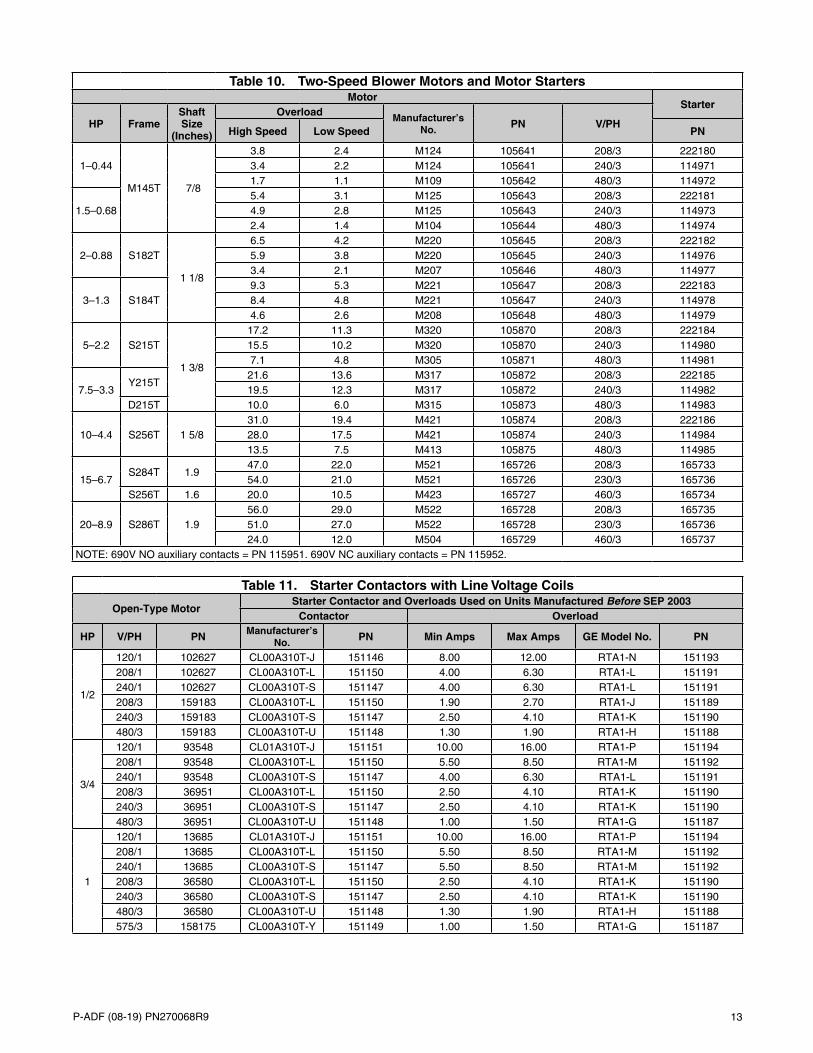
Table 10. Two-Speed Blower Motors and Motor StartersMotor
Starter
HP FrameShaft Size
(Inches)
Overload Manufacturer’s No. PN V/PH
High Speed Low Speed PN
1–0.44
M145T 7/8
3.8 2.4 M124 105641 208/3 2221803.4 2.2 M124 105641 240/3 1149711.7 1.1 M109 105642 480/3 114972
1.5–0.685.4 3.1 M125 105643 208/3 2221814.9 2.8 M125 105643 240/3 1149732.4 1.4 M104 105644 480/3 114974
2–0.88 S182T
1 1/8
6.5 4.2 M220 105645 208/3 2221825.9 3.8 M220 105645 240/3 1149763.4 2.1 M207 105646 480/3 114977
3–1.3 S184T9.3 5.3 M221 105647 208/3 2221838.4 4.8 M221 105647 240/3 1149784.6 2.6 M208 105648 480/3 114979
5–2.2 S215T
1 3/8
17.2 11.3 M320 105870 208/3 22218415.5 10.2 M320 105870 240/3 1149807.1 4.8 M305 105871 480/3 114981
7.5–3.3Y215T
21.6 13.6 M317 105872 208/3 22218519.5 12.3 M317 105872 240/3 114982
D215T 10.0 6.0 M315 105873 480/3 114983
10–4.4 S256T 1 5/831.0 19.4 M421 105874 208/3 22218628.0 17.5 M421 105874 240/3 11498413.5 7.5 M413 105875 480/3 114985
15–6.7S284T 1.9
47.0 22.0 M521 165726 208/3 16573354.0 21.0 M521 165726 230/3 165736
S256T 1.6 20.0 10.5 M423 165727 460/3 165734
20–8.9 S286T 1.956.0 29.0 M522 165728 208/3 16573551.0 27.0 M522 165728 230/3 16573624.0 12.0 M504 165729 460/3 165737
NOTE: 690V NO auxiliary contacts = PN 115951. 690V NC auxiliary contacts = PN 115952.
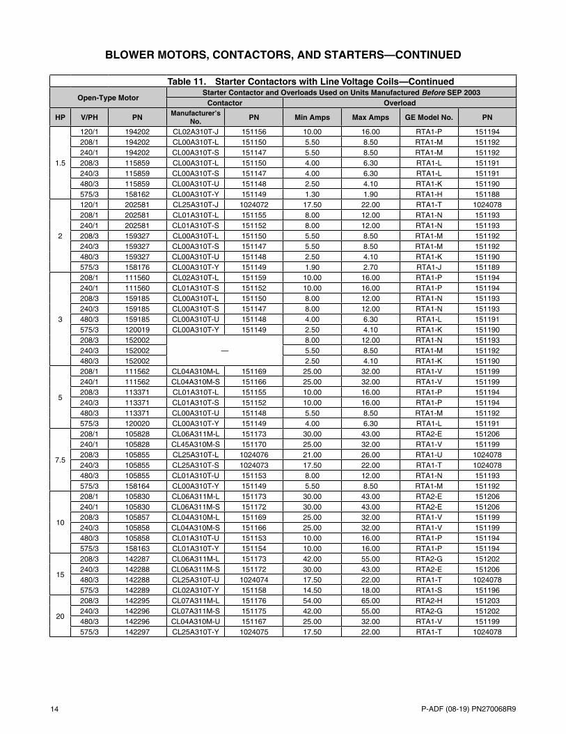
Table 11. Starter Contactors with Line Voltage Coils
Open-Type MotorStarter Contactor and Overloads Used on Units Manufactured Before SEP 2003
Contactor Overload
HP V/PH PN Manufacturer’s No. PN Min Amps Max Amps GE Model No. PN
1/2
120/1 102627 CL00A310T-J 151146 8.00 12.00 RTA1-N 151193208/1 102627 CL00A310T-L 151150 4.00 6.30 RTA1-L 151191240/1 102627 CL00A310T-S 151147 4.00 6.30 RTA1-L 151191208/3 159183 CL00A310T-L 151150 1.90 2.70 RTA1-J 151189240/3 159183 CL00A310T-S 151147 2.50 4.10 RTA1-K 151190480/3 159183 CL00A310T-U 151148 1.30 1.90 RTA1-H 151188
3/4
120/1 93548 CL01A310T-J 151151 10.00 16.00 RTA1-P 151194208/1 93548 CL00A310T-L 151150 5.50 8.50 RTA1-M 151192240/1 93548 CL00A310T-S 151147 4.00 6.30 RTA1-L 151191208/3 36951 CL00A310T-L 151150 2.50 4.10 RTA1-K 151190240/3 36951 CL00A310T-S 151147 2.50 4.10 RTA1-K 151190480/3 36951 CL00A310T-U 151148 1.00 1.50 RTA1-G 151187
1
120/1 13685 CL01A310T-J 151151 10.00 16.00 RTA1-P 151194208/1 13685 CL00A310T-L 151150 5.50 8.50 RTA1-M 151192240/1 13685 CL00A310T-S 151147 5.50 8.50 RTA1-M 151192208/3 36580 CL00A310T-L 151150 2.50 4.10 RTA1-K 151190240/3 36580 CL00A310T-S 151147 2.50 4.10 RTA1-K 151190480/3 36580 CL00A310T-U 151148 1.30 1.90 RTA1-H 151188575/3 158175 CL00A310T-Y 151149 1.00 1.50 RTA1-G 151187
14 P-ADF (08-19) PN270068R9
BLOWER MOTORS, CONTACTORS, AND STARTERS—CONTINUED
Table 11. Starter Contactors with Line Voltage Coils
Open-Type MotorStarter Contactor and Overloads Used on Units Manufactured Before SEP 2003
Contactor Overload
HP V/PH PN Manufacturer’s No. PN Min Amps Max Amps GE Model No. PN
1.5
120/1 194202 CL02A310T-J 151156 10.00 16.00 RTA1-P 151194208/1 194202 CL00A310T-L 151150 5.50 8.50 RTA1-M 151192240/1 194202 CL00A310T-S 151147 5.50 8.50 RTA1-M 151192208/3 115859 CL00A310T-L 151150 4.00 6.30 RTA1-L 151191240/3 115859 CL00A310T-S 151147 4.00 6.30 RTA1-L 151191480/3 115859 CL00A310T-U 151148 2.50 4.10 RTA1-K 151190575/3 158162 CL00A310T-Y 151149 1.30 1.90 RTA1-H 151188
2
120/1 202581 CL25A310T-J 1024072 17.50 22.00 RTA1-T 1024078208/1 202581 CL01A310T-L 151155 8.00 12.00 RTA1-N 151193240/1 202581 CL01A310T-S 151152 8.00 12.00 RTA1-N 151193208/3 159327 CL00A310T-L 151150 5.50 8.50 RTA1-M 151192240/3 159327 CL00A310T-S 151147 5.50 8.50 RTA1-M 151192480/3 159327 CL00A310T-U 151148 2.50 4.10 RTA1-K 151190575/3 158176 CL00A310T-Y 151149 1.90 2.70 RTA1-J 151189
3
208/1 111560 CL02A310T-L 151159 10.00 16.00 RTA1-P 151194240/1 111560 CL01A310T-S 151152 10.00 16.00 RTA1-P 151194208/3 159185 CL00A310T-L 151150 8.00 12.00 RTA1-N 151193240/3 159185 CL00A310T-S 151147 8.00 12.00 RTA1-N 151193480/3 159185 CL00A310T-U 151148 4.00 6.30 RTA1-L 151191575/3 120019 CL00A310T-Y 151149 2.50 4.10 RTA1-K 151190208/3 152002
—8.00 12.00 RTA1-N 151193
240/3 152002 5.50 8.50 RTA1-M 151192480/3 152002 2.50 4.10 RTA1-K 151190
5
208/1 111562 CL04A310M-L 151169 25.00 32.00 RTA1-V 151199240/1 111562 CL04A310M-S 151166 25.00 32.00 RTA1-V 151199208/3 113371 CL01A310T-L 151155 10.00 16.00 RTA1-P 151194240/3 113371 CL01A310T-S 151152 10.00 16.00 RTA1-P 151194480/3 113371 CL00A310T-U 151148 5.50 8.50 RTA1-M 151192575/3 120020 CL00A310T-Y 151149 4.00 6.30 RTA1-L 151191
7.5
208/1 105828 CL06A311M-L 151173 30.00 43.00 RTA2-E 151206240/1 105828 CL45A310M-S 151170 25.00 32.00 RTA1-V 151199208/3 105855 CL25A310T-L 1024076 21.00 26.00 RTA1-U 1024078240/3 105855 CL25A310T-S 1024073 17.50 22.00 RTA1-T 1024078480/3 105855 CL01A310T-U 151153 8.00 12.00 RTA1-N 151193575/3 158164 CL00A310T-Y 151149 5.50 8.50 RTA1-M 151192
10
208/1 105830 CL06A311M-L 151173 30.00 43.00 RTA2-E 151206240/1 105830 CL06A311M-S 151172 30.00 43.00 RTA2-E 151206208/3 105857 CL04A310M-L 151169 25.00 32.00 RTA1-V 151199240/3 105858 CL04A310M-S 151166 25.00 32.00 RTA1-V 151199480/3 105858 CL01A310T-U 151153 10.00 16.00 RTA1-P 151194575/3 158163 CL01A310T-Y 151154 10.00 16.00 RTA1-P 151194
15
208/3 142287 CL06A311M-L 151173 42.00 55.00 RTA2-G 151202240/3 142288 CL06A311M-S 151172 30.00 43.00 RTA2-E 151206480/3 142288 CL25A310T-U 1024074 17.50 22.00 RTA1-T 1024078575/3 142289 CL02A310T-Y 151158 14.50 18.00 RTA1-S 151196
20
208/3 142295 CL07A311M-L 151176 54.00 65.00 RTA2-H 151203240/3 142296 CL07A311M-S 151175 42.00 55.00 RTA2-G 151202480/3 142296 CL04A310M-U 151167 25.00 32.00 RTA1-V 151199575/3 142297 CL25A310T-Y 1024075 17.50 22.00 RTA1-T 1024078
—Continued
P-ADF (08-19) PN270068R9 15
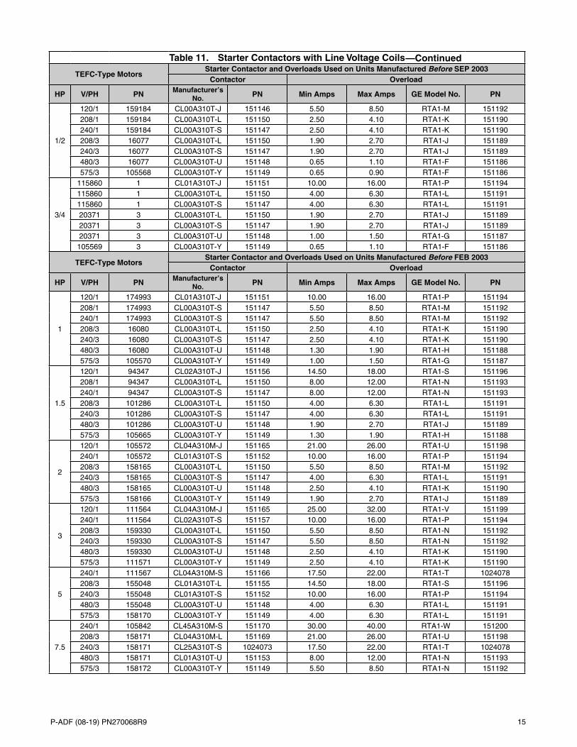
Table 11. Starter Contactors with Line Voltage Coils
TEFC-Type MotorsStarter Contactor and Overloads Used on Units Manufactured Before SEP 2003
Contactor Overload
HP V/PH PN Manufacturer’s No. PN Min Amps Max Amps GE Model No. PN
1/2
120/1 159184 CL00A310T-J 151146 5.50 8.50 RTA1-M 151192208/1 159184 CL00A310T-L 151150 2.50 4.10 RTA1-K 151190240/1 159184 CL00A310T-S 151147 2.50 4.10 RTA1-K 151190208/3 16077 CL00A310T-L 151150 1.90 2.70 RTA1-J 151189240/3 16077 CL00A310T-S 151147 1.90 2.70 RTA1-J 151189480/3 16077 CL00A310T-U 151148 0.65 1.10 RTA1-F 151186575/3 105568 CL00A310T-Y 151149 0.65 0.90 RTA1-F 151186
3/4
115860 1 CL01A310T-J 151151 10.00 16.00 RTA1-P 151194115860 1 CL00A310T-L 151150 4.00 6.30 RTA1-L 151191115860 1 CL00A310T-S 151147 4.00 6.30 RTA1-L 15119120371 3 CL00A310T-L 151150 1.90 2.70 RTA1-J 15118920371 3 CL00A310T-S 151147 1.90 2.70 RTA1-J 15118920371 3 CL00A310T-U 151148 1.00 1.50 RTA1-G 151187105569 3 CL00A310T-Y 151149 0.65 1.10 RTA1-F 151186
TEFC-Type MotorsStarter Contactor and Overloads Used on Units Manufactured Before FEB 2003
Contactor Overload
HP V/PH PN Manufacturer’s No. PN Min Amps Max Amps GE Model No. PN
1
120/1 174993 CL01A310T-J 151151 10.00 16.00 RTA1-P 151194208/1 174993 CL00A310T-S 151147 5.50 8.50 RTA1-M 151192240/1 174993 CL00A310T-S 151147 5.50 8.50 RTA1-M 151192208/3 16080 CL00A310T-L 151150 2.50 4.10 RTA1-K 151190240/3 16080 CL00A310T-S 151147 2.50 4.10 RTA1-K 151190480/3 16080 CL00A310T-U 151148 1.30 1.90 RTA1-H 151188575/3 105570 CL00A310T-Y 151149 1.00 1.50 RTA1-G 151187
1.5
120/1 94347 CL02A310T-J 151156 14.50 18.00 RTA1-S 151196208/1 94347 CL00A310T-L 151150 8.00 12.00 RTA1-N 151193240/1 94347 CL00A310T-S 151147 8.00 12.00 RTA1-N 151193208/3 101286 CL00A310T-L 151150 4.00 6.30 RTA1-L 151191240/3 101286 CL00A310T-S 151147 4.00 6.30 RTA1-L 151191480/3 101286 CL00A310T-U 151148 1.90 2.70 RTA1-J 151189575/3 105665 CL00A310T-Y 151149 1.30 1.90 RTA1-H 151188
2
120/1 105572 CL04A310M-J 151165 21.00 26.00 RTA1-U 151198240/1 105572 CL01A310T-S 151152 10.00 16.00 RTA1-P 151194208/3 158165 CL00A310T-L 151150 5.50 8.50 RTA1-M 151192240/3 158165 CL00A310T-S 151147 4.00 6.30 RTA1-L 151191480/3 158165 CL00A310T-U 151148 2.50 4.10 RTA1-K 151190575/3 158166 CL00A310T-Y 151149 1.90 2.70 RTA1-J 151189
3
120/1 111564 CL04A310M-J 151165 25.00 32.00 RTA1-V 151199240/1 111564 CL02A310T-S 151157 10.00 16.00 RTA1-P 151194208/3 159330 CL00A310T-L 151150 5.50 8.50 RTA1-N 151192240/3 159330 CL00A310T-S 151147 5.50 8.50 RTA1-N 151192480/3 159330 CL00A310T-U 151148 2.50 4.10 RTA1-K 151190575/3 111571 CL00A310T-Y 151149 2.50 4.10 RTA1-K 151190
5
240/1 111567 CL04A310M-S 151166 17.50 22.00 RTA1-T 1024078208/3 155048 CL01A310T-L 151155 14.50 18.00 RTA1-S 151196240/3 155048 CL01A310T-S 151152 10.00 16.00 RTA1-P 151194480/3 155048 CL00A310T-U 151148 4.00 6.30 RTA1-L 151191575/3 158170 CL00A310T-Y 151149 4.00 6.30 RTA1-L 151191
7.5
240/1 105842 CL45A310M-S 151170 30.00 40.00 RTA1-W 151200208/3 158171 CL04A310M-L 151169 21.00 26.00 RTA1-U 151198240/3 158171 CL25A310T-S 1024073 17.50 22.00 RTA1-T 1024078480/3 158171 CL01A310T-U 151153 8.00 12.00 RTA1-N 151193575/3 158172 CL00A310T-Y 151149 5.50 8.50 RTA1-N 151192
—Continued
16 P-ADF (08-19) PN270068R9
BLOWER MOTORS, CONTACTORS, AND STARTERS—CONTINUED
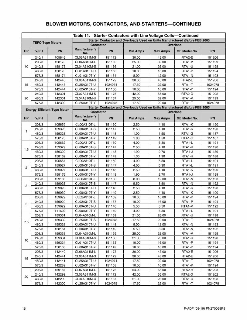
Table 11. Starter Contactors with Line Voltage Coils
TEFC-Type MotorsStarter Contactor and Overloads Used on Units Manufactured Before FEB 2003
Contactor Overload
HP V/PH PN Manufacturer’s No. PN Min Amps Max Amps GE Model No. PN
10
240/1 105846 CL06A311M-S 151172 30.00 43.00 RTA2-E 151206208/3 158173 CL04A310M-L 151169 25.00 32.00 RTA1-V 151199240/3 158173 CL04A310M-S 151166 21.00 26.00 RTA1-U 151198480/3 158173 CL01A310T-U 151153 10.00 16.00 RTA1-P 151194575/3 158174 CL01A310T-Y 151154 8.00 12.00 RTA1-N 151193
15240/3 142443 CL06A311M-S 151172 30.00 43.00 RTA2-E 151206480/3 142443 CL25A310T-U 1024074 17.50 22.00 RTA1-T 1024078575/3 142444 CL02A310T-Y 151158 10.00 16.00 RTA1-P 151194
20240/3 142301 CL07A311M-S 151175 42.00 55.00 RTA2-G 151202480/3 142301 CL04A310M-U 151167 25.00 32.00 RTA1-V 151199575/3 142302 CL25A310T-Y 1024075 17.50 22.00 RTA1-T 1024078
Energy-Efficient-Type MotorStarter Contactor and Overloads Used on Units Manufactured Before FEB 2003
Contactor Overload
HP V/PH PN Manufacturer’s No. PN Min Amps Max Amps GE Model No. PN
1
208/3 105659 CL00A310T-L 151150 2.50 4.10 RTA1-K 151190240/3 159328 CL00A310T-S 151147 2.50 4.10 RTA1-K 151190480/3 159328 CL00A310T-U 151148 1.00 1.50 RTA1-G 151187575/3 158175 CL00A310T-Y 151149 1.00 1.50 RTA1-G 151187
1.5
208/3 105662 CL00A310T-L 151150 4.00 6.30 RTA1-L 151191240/3 159329 CL00A310T-S 151147 2.50 4.10 RTA1-K 151190480/3 159329 CL00A310T-U 151148 1.90 2.70 RTA1-J 151189575/3 158162 CL00A310T-Y 151149 1.30 1.90 RTA1-H 151188
2
208/3 105664 CL00A310T-L 151150 4.00 6.30 RTA1-L 151191240/3 159027 CL00A310T-S 151147 4.00 6.30 RTA1-L 151191480/3 159027 CL00A310T-U 151148 2.50 4.10 RTA1-K 151190575/3 158176 CL00A310T-Y 151149 1.90 2.70 RTA1-J 151189
3
208/3 159186 CL00A310T-L 151150 8.00 12.00 RTA1-N 151193240/3 159028 CL00A310T-S 151147 5.50 8.50 RTA1-N 151192480/3 159028 CL00A310T-U 151148 2.50 4.10 RTA1-K 151190575/3 159030 CL00A310T-Y 151149 2.50 4.10 RTA1-K 151190
5
208/3 159029 CL02A310T-L 151159 10.00 16.00 RTA1-P 151194240/3 159029 CL02A310T-S 151157 10.00 16.00 RTA1-P 151194480/3 159029 CL00A310T-U 151148 5.50 8.50 RTA1-M 151192575/3 111602 CL00A310T-Y 151149 4.00 6.30 RTA1-L 151191
7.5
208/3 159331 CL04A310M-L 151169 21.00 26.00 RTA1-U 151198240/3 159332 CL25A310T-S 1024073 17.50 22.00 RTA1-T 1024078480/3 159332 CL00A310T-U 151148 8.00 12.00 RTA1-N 151193575/3 158164 CL00A310T-Y 151149 5.50 8.50 RTA1-N 151192
10
208/3 159333 CL04A310M-L 151169 25.00 32.00 RTA1-V 151199240/3 159334 CL04A310M-S 151166 21.00 26.00 RTA1-U 151198480/3 159334 CL01A310T-U 151153 10.00 16.00 RTA1-P 151194575/3 158163 CL00A310T-Y 151149 10.00 16.00 RTA1-P 151194
15
208/3 142440 CL06A311M-L 151173 30.00 43.00 RTA2-E 151206240/1 142441 CL06A311M-S 151172 30.00 43.00 RTA2-E 151206480/3 142441 CL25A310T-U 1024074 17.50 22.00 RTA1-T 1024078575/3 142289 CL02A310T-Y 151158 10.00 16.00 RTA1-P 151194
20
208/3 159187 CL07A311M-L 151176 54.00 65.00 RTA2-H 151203240/3 142299 CL06A311M-S 151172 42.00 55.00 RTA2-G 151202480/3 142299 CL04A310M-U 151167 21.00 26.00 RTA1-U 151198575/3 142300 CL25A310T-Y 1024075 17.50 22.00 RTA1-T 1024078
—Continued
P-ADF (08-19) PN270068R9 17
Table 12. Replacement Coils by Voltage for IEC Starter Contactors
Voltage
For Contactors with GE Model No. Beginning with
CL00, CL01, CL02, or CL25
For Contactors with GE Model No. Beginning with
CL04 or CL45
For Contactors with GE Model No. Beginning with
CL06, CL07, CL08, or CL09GE Model No. PN GE Model No. PN GE Model No. PN
24 LB1A-C 151280 LB3A-C 151286—
120 LB1A-J 151281 LB3A-J 151287208 LB1A-L 151282 LB3A-L 151288 LB4A-L 151292230 LB1A-S 151283 LB3A-S 151289 LB4A-S 151293460 LB1A-U 151284 LB3A-U 151290 LB4A-U 151294575 LB1A-Y 151285 LB3A-Y 151291 —
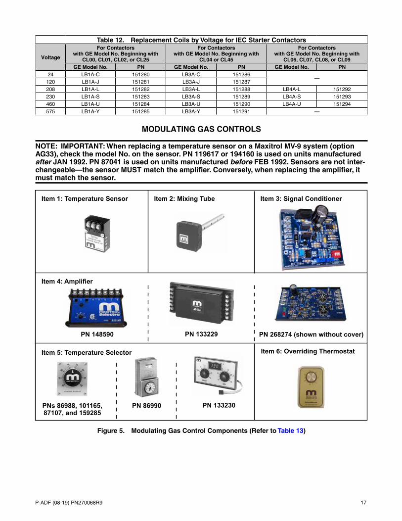
MODULATING GAS CONTROLS
NOTE: IMPORTANT: When replacing a temperature sensor on a Maxitrol MV-9 system (option AG33), check the model No. on the sensor. PN 119617 or 194160 is used on units manufactured after JAN 1992. PN 87041 is used on units manufactured before FEB 1992. Sensors are not inter-changeable—the sensor MUST match the amplifier. Conversely, when replacing the amplifier, it must match the sensor.
Item 1: Temperature Sensor Item 2: Mixing Tube
Item 4: Amplifier
PN 148590 PN 268274 (shown without cover)
Item 3: Signal Conditioner
PN 133229
Item 6: Overriding ThermostatItem 5: Temperature Selector
PN 133230PN 86990PNs 86988, 101165, 87107, and 159285
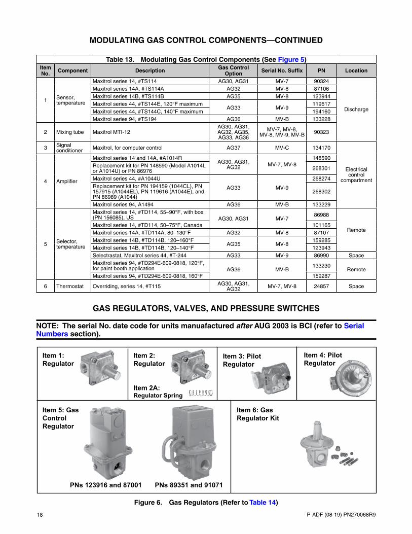
Figure 5. Modulating Gas Control Components (Refer to Table 13)
18 P-ADF (08-19) PN270068R9
MODULATING GAS CONTROL COMPONENTS—CONTINUED
Table 13. Modulating Gas Control Components (See Figure 5)Item No. Component Description Gas Control
Option Serial No. Suffix PN Location
1 Sensor, temperature
Maxitrol series 14, #TS114 AG30, AG31 MV-7 90324
Discharge
Maxitrol series 14A, #TS114A AG32 MV-8 87106Maxitrol series 14B, #TS114B AG35 MV-8 123944Maxitrol series 44, #TS144E, 120°F maximum
AG33 MV-9119617
Maxitrol series 44, #TS144C, 140°F maximum 194160Maxitrol series 94, #TS194 AG36 MV-B 133228
2 Mixing tube Maxitrol MTI-12AG30, AG31, AG32, AG35, AG33, AG36
MV-7, MV-8, MV-8, MV-9, MV-B 90323
3 Signal conditioner Maxitrol, for computer control AG37 MV-C 134170
Electrical control
compartment4 Amplifier
Maxitrol series 14 and 14A, #A1014RAG30, AG31,
AG32 MV-7, MV-8148590
Replacement kit for PN 148590 (Model A1014L or A1014U) or PN 86976 268301
Maxitrol series 44, #A1044U
AG33 MV-9
268274Replacement kit for PN 194159 (1044CL), PN 157915 (A1044EL), PN 119616 (A1044E), and PN 86989 (A1044)
268302
Maxitrol series 94, A1494 AG36 MV-B 133229
5 Selector, temperature
Maxitrol series 14, #TD114, 55–90°F, with box (PN 156085), US AG30, AG31 MV-7
86988
RemoteMaxitrol series 14, #TD114, 50–75°F, Canada 101165Maxitrol series 14A, #TD114A, 80–130°F AG32 MV-8 87107Maxitrol series 14B, #TD114B, 120–160°F
AG35 MV-8159285
Maxitrol series 14B, #TD114B, 120–140°F 123943Selectrastat, Maxitrol series 44, #T-244 AG33 MV-9 86990 SpaceMaxitrol series 94, #TD294E-609-0818, 120°F, for paint booth application AG36 MV-B
133230Remote
Maxitrol series 94, #TD294E-609-0818, 160°F 159287
6 Thermostat Overriding, series 14, #T115 AG30, AG31, AG32 MV-7, MV-8 24857 Space
GAS REGULATORS, VALVES, AND PRESSURE SWITCHES
NOTE: The serial No. date code for units manuafactured after AUG 2003 is BCI (refer to Serial Numbers section).
Figure 6. Gas Regulators (Refer to Table 14)
Item 2: Regulator Item 2A: Regulator Spring
Item 4: Pilot Regulator
Item 1: Regulator
Item 3: Pilot Regulator
Item 5: Gas Control Regulator
Item 6: Gas Regulator Kit
PNs 123916 and 87001 PNs 89351 and 91071

P-ADF (08-19) PN270068R9 19
Figure 7. Valves (Refer to Table 14)
Figure 8. Pressure Switches (Refer to Table 14)
Item 11: Single-StageValve
PN 121599 PN 222037
Item 9: Solenoid Valve
Item 10: Solenoid Valve
Item 12: Gas Valve
Item 11A: Air Controller
Item 7: Pilot Valve
Item 8: Pilot Valve
Item 13: Gas Valve
Item 13A: Ductstat
Item 15: Modulation Valve
Item 14: Two-Stage Valve
Item 17: Vent Valve Item 18: Gas Valve with Adapter
Item 19: Pilot Gas Valve
Item 16: Valve Item 16A:
Actuator
PN 204375
Item 21A: Vent Limiter for Pressure Switches
Item 21: Pressure Switches
PN 204297 PN 93850PN 93849
20 P-ADF (08-19) PN270068R9
GAS REGULATORS, VALVES, AND PRESSURE SWITCHES—CONTINUED
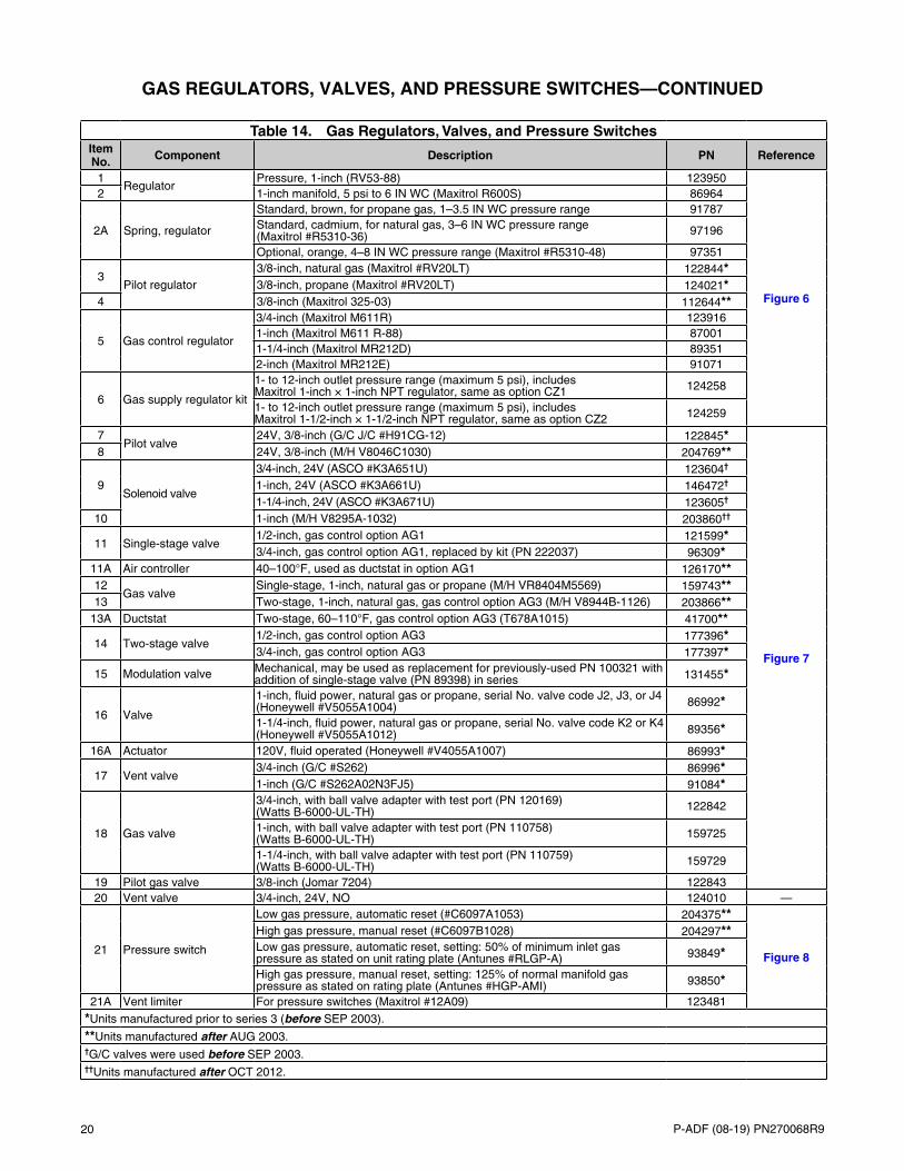
Table 14. Gas Regulators, Valves, and Pressure SwitchesItem No. Component Description PN Reference
1Regulator
Pressure, 1-inch (RV53-88) 123950
Figure 6
2 1-inch manifold, 5 psi to 6 IN WC (Maxitrol R600S) 86964
2A Spring, regulator
Standard, brown, for propane gas, 1–3.5 IN WC pressure range 91787Standard, cadmium, for natural gas, 3–6 IN WC pressure range (Maxitrol #R5310-36) 97196
Optional, orange, 4–8 IN WC pressure range (Maxitrol #R5310-48) 97351
3Pilot regulator
3/8-inch, natural gas (Maxitrol #RV20LT) 122844*3/8-inch, propane (Maxitrol #RV20LT) 124021*
4 3/8-inch (Maxitrol 325-03) 112644**
5 Gas control regulator
3/4-inch (Maxitrol M611R) 1239161-inch (Maxitrol M611 R-88) 870011-1/4-inch (Maxitrol MR212D) 893512-inch (Maxitrol MR212E) 91071
6 Gas supply regulator kit
1- to 12-inch outlet pressure range (maximum 5 psi), includes Maxitrol 1-inch × 1-inch NPT regulator, same as option CZ1 124258
1- to 12-inch outlet pressure range (maximum 5 psi), includes Maxitrol 1-1/2-inch × 1-1/2-inch NPT regulator, same as option CZ2 124259
7Pilot valve
24V, 3/8-inch (G/C J/C #H91CG-12) 122845*
Figure 7
8 24V, 3/8-inch (M/H V8046C1030) 204769**
9Solenoid valve
3/4-inch, 24V (ASCO #K3A651U) 123604†
1-inch, 24V (ASCO #K3A661U) 146472†
1-1/4-inch, 24V (ASCO #K3A671U) 123605†
10 1-inch (M/H V8295A-1032) 203860††
11 Single-stage valve1/2-inch, gas control option AG1 121599*3/4-inch, gas control option AG1, replaced by kit (PN 222037) 96309*
11A Air controller 40–100°F, used as ductstat in option AG1 126170**12
Gas valveSingle-stage, 1-inch, natural gas or propane (M/H VR8404M5569) 159743**
13 Two-stage, 1-inch, natural gas, gas control option AG3 (M/H V8944B-1126) 203866**13A Ductstat Two-stage, 60–110°F, gas control option AG3 (T678A1015) 41700**
14 Two-stage valve1/2-inch, gas control option AG3 177396*3/4-inch, gas control option AG3 177397*
15 Modulation valve Mechanical, may be used as replacement for previously-used PN 100321 with addition of single-stage valve (PN 89398) in series 131455*
16 Valve
1-inch, fluid power, natural gas or propane, serial No. valve code J2, J3, or J4 (Honeywell #V5055A1004) 86992*
1-1/4-inch, fluid power, natural gas or propane, serial No. valve code K2 or K4 (Honeywell #V5055A1012) 89356*
16A Actuator 120V, fluid operated (Honeywell #V4055A1007) 86993*
17 Vent valve3/4-inch (G/C #S262) 86996*1-inch (G/C #S262A02N3FJ5) 91084*
18 Gas valve
3/4-inch, with ball valve adapter with test port (PN 120169) (Watts B-6000-UL-TH) 122842
1-inch, with ball valve adapter with test port (PN 110758) (Watts B-6000-UL-TH) 159725
1-1/4-inch, with ball valve adapter with test port (PN 110759) (Watts B-6000-UL-TH) 159729
19 Pilot gas valve 3/8-inch (Jomar 7204) 12284320 Vent valve 3/4-inch, 24V, NO 124010 —
21 Pressure switch
Low gas pressure, automatic reset (#C6097A1053) 204375**
Figure 8
High gas pressure, manual reset (#C6097B1028) 204297**Low gas pressure, automatic reset, setting: 50% of minimum inlet gas pressure as stated on unit rating plate (Antunes #RLGP-A) 93849*
High gas pressure, manual reset, setting: 125% of normal manifold gas pressure as stated on rating plate (Antunes #HGP-AMI) 93850*
21A Vent limiter For pressure switches (Maxitrol #12A09) 123481
*Units manufactured prior to series 3 (before SEP 2003).
**Units manufactured after AUG 2003.†G/C valves were used before SEP 2003.††Units manufactured after OCT 2012.
P-ADF (08-19) PN270068R9 21
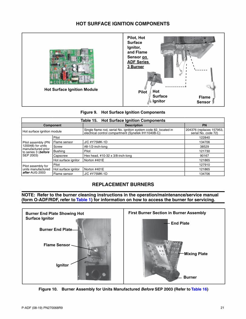
HOT SURFACE IGNITION COMPONENTS
Hot Surface Ignition Module Pilot Hot Surface Ignitor
Flame Sensor
Pilot, Hot Surface Ignitor, and Flame Sensor on ADF Series 3 Burner
Figure 9. Hot Surface Ignition Components
Table 15. Hot Surface Ignition ComponentsComponent Description PN
Hot surface ignition module Single flame rod, serial No. ignition system code 82, located in electrical control compartment (Synetek IH11040B-C)
204376 (replaces 157953, serial No. code 72)
Pilot assembly (PN 120048) for units manufactured prior to series 3 (before SEP 2003)
Pilot 122840Flame sensor J/C #Y75MK-1D 134706Screw #8-1/2-inch-long 38529Bushing Pilot 121730Capscrew Hex head, #10-32 x 3/8-inch-long 90167Hot surface ignitor Norton #401E 121865
Pilot assembly for units manufactured after AUG 2003
Pilot 127910Hot surface ignitor Norton #401E 121865Flame sensor J/C #Y75MK-1D 134706
REPLACEMENT BURNERS
NOTE: Refer to the burner cleaning instructions in the operation/maintenance/service manual (form O-ADF/RDF, refer to Table 1) for information on how to access the burner for servicing.
Figure 10. Burner Assembly for Units Manufactured Before SEP 2003 (Refer to Table 16)
First Burner Section in Burner Assembly
End Plate
Mixing Plate
Burner
Burner End Plate Showing Hot Surface Ignitor
Ignitor
Flame Sensor
Burner End Plate
22 P-ADF (08-19) PN270068R9
REPLACEMENT BURNERS—CONTINUED
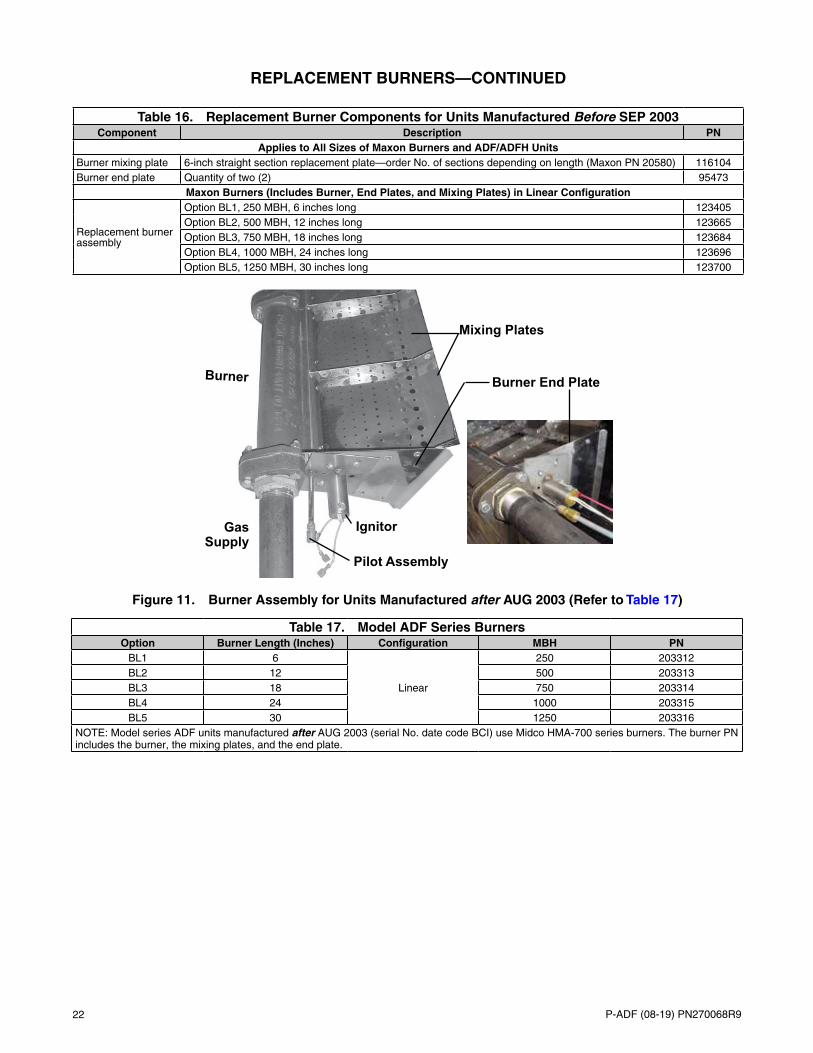
Table 16. Replacement Burner Components for Units Manufactured Before SEP 2003Component Description PN
Applies to All Sizes of Maxon Burners and ADF/ADFH UnitsBurner mixing plate 6-inch straight section replacement plate—order No. of sections depending on length (Maxon PN 20580) 116104Burner end plate Quantity of two (2) 95473
Maxon Burners (Includes Burner, End Plates, and Mixing Plates) in Linear Configuration
Replacement burner assembly
Option BL1, 250 MBH, 6 inches long 123405Option BL2, 500 MBH, 12 inches long 123665Option BL3, 750 MBH, 18 inches long 123684Option BL4, 1000 MBH, 24 inches long 123696Option BL5, 1250 MBH, 30 inches long 123700
Burner
Mixing Plates
IgnitorGas Supply
Pilot Assembly
Burner End Plate
Table 17. Model ADF Series BurnersOption Burner Length (Inches) Configuration MBH PN
BL1 6
Linear
250 203312BL2 12 500 203313BL3 18 750 203314BL4 24 1000 203315BL5 30 1250 203316
NOTE: Model series ADF units manufactured after AUG 2003 (serial No. date code BCI) use Midco HMA-700 series burners. The burner PN includes the burner, the mixing plates, and the end plate.
Figure 11. Burner Assembly for Units Manufactured after AUG 2003 (Refer to Table 17)
P-ADF (08-19) PN270068R9 23
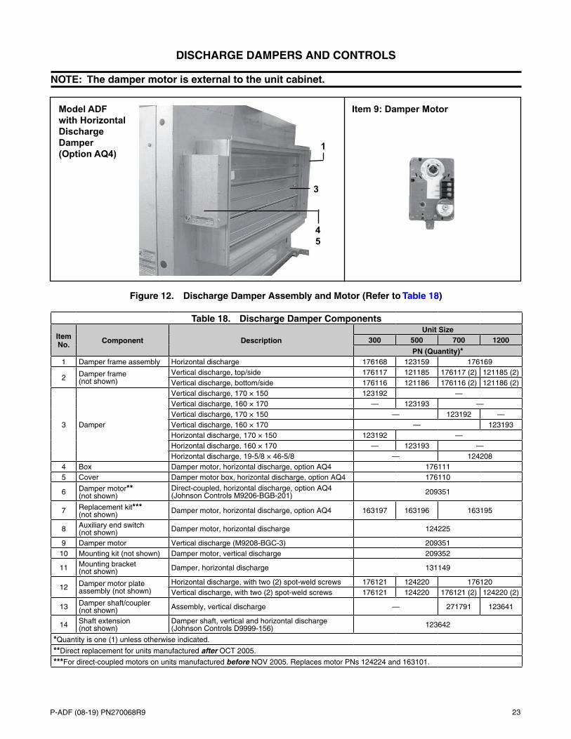
DISCHARGE DAMPERS AND CONTROLS
NOTE: The damper motor is external to the unit cabinet.
Table 18. Discharge Damper Components
Item No. Component Description
Unit Size300 500 700 1200
PN (Quantity)*1 Damper frame assembly Horizontal discharge 176168 123159 176169
2 Damper frame (not shown)
Vertical discharge, top/side 176117 121185 176117 (2) 121185 (2)Vertical discharge, bottom/side 176116 121186 176116 (2) 121186 (2)
3 Damper
Vertical discharge, 170 × 150 123192 —Vertical discharge, 160 × 170 — 123193 —Vertical discharge, 170 × 150 — 123192 —Vertical discharge, 160 × 170 — 123193Horizontal discharge, 170 × 150 123192 —Horizontal discharge, 160 × 170 — 123193 —Horizontal discharge, 19-5/8 × 46-5/8 — 124208
4 Box Damper motor, horizontal discharge, option AQ4 1761115 Cover Damper motor box, horizontal discharge, option AQ4 176110
6 Damper motor** (not shown)
Direct-coupled, horizontal discharge, option AQ4 (Johnson Controls M9206-BGB-201) 209351
7 Replacement kit*** (not shown) Damper motor, horizontal discharge, option AQ4 163197 163196 163195
8 Auxiliary end switch (not shown) Damper motor, horizontal discharge 124225
9 Damper motor Vertical discharge (M9208-BGC-3) 20935110 Mounting kit (not shown) Damper motor, vertical discharge 209352
11 Mounting bracket (not shown) Damper, horizontal discharge 131149
12 Damper motor plate assembly (not shown)
Horizontal discharge, with two (2) spot-weld screws 176121 124220 176120Vertical discharge, with two (2) spot-weld screws 176121 124220 176121 (2) 124220 (2)
13 Damper shaft/coupler (not shown) Assembly, vertical discharge — 271791 123641
14 Shaft extension (not shown)
Damper shaft, vertical and horizontal discharge (Johnson Controls D9999-156) 123642
*Quantity is one (1) unless otherwise indicated.
**Direct replacement for units manufactured after OCT 2005.
***For direct-coupled motors on units manufactured before NOV 2005. Replaces motor PNs 124224 and 163101.
Figure 12. Discharge Damper Assembly and Motor (Refer to Table 18)
Item 9: Damper MotorModel ADF with Horizontal Discharge Damper (Option AQ4)
4 5
1
3
24 P-ADF (08-19) PN270068R9
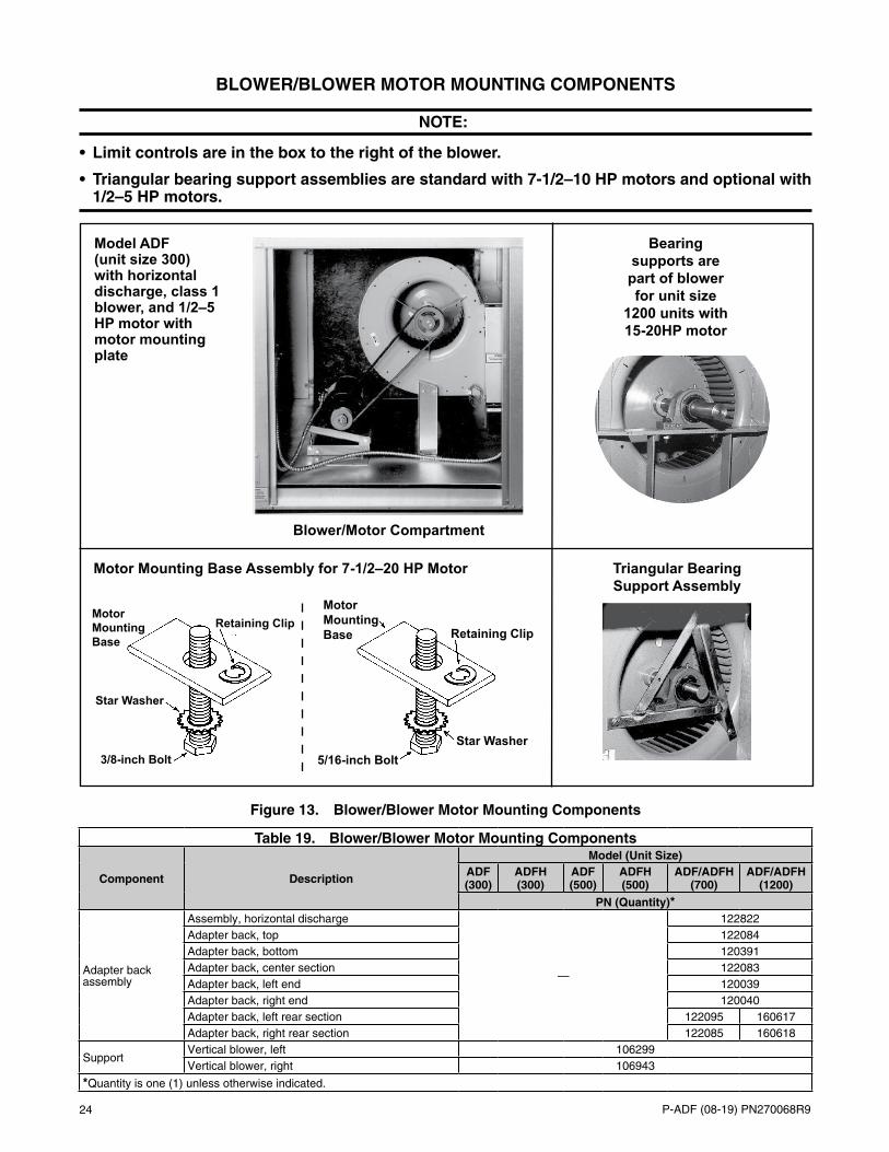
BLOWER/BLOWER MOTOR MOUNTING COMPONENTS
NOTE:
• Limit controls are in the box to the right of the blower.
• Triangular bearing support assemblies are standard with 7-1/2–10 HP motors and optional with 1/2–5 HP motors.
Table 19. Blower/Blower Motor Mounting Components
Component Description
Model (Unit Size)ADF (300)
ADFH (300)
ADF (500)
ADFH (500)
ADF/ADFH (700)
ADF/ADFH (1200)
PN (Quantity)*
Adapter back assembly
Assembly, horizontal discharge
—
122822Adapter back, top 122084Adapter back, bottom 120391Adapter back, center section 122083Adapter back, left end 120039Adapter back, right end 120040Adapter back, left rear section 122095 160617Adapter back, right rear section 122085 160618
SupportVertical blower, left 106299Vertical blower, right 106943
*Quantity is one (1) unless otherwise indicated.
Model ADF (unit size 300) with horizontal discharge, class 1 blower, and 1/2–5 HP motor with motor mounting plate
Bearing supports are part of blower for unit size
1200 units with 15-20HP motor
Triangular Bearing Support Assembly
Motor Mounting Base Assembly for 7-1/2–20 HP Motor
Blower/Motor Compartment
Retaining Clip
3/8-inch Bolt
Star Washer
Motor Mounting Base Retaining Clip
Star Washer5/16-inch Bolt
Motor Mounting Base
Figure 13. Blower/Blower Motor Mounting Components
P-ADF (08-19) PN270068R9 25
Table 19. Blower/Blower Motor Mounting Components
Component Description
Model (Unit Size)ADF (300)
ADFH (300)
ADF (500)
ADFH (500)
ADF/ADFH (700)
ADF/ADFH (1200)
PN (Quantity)*
Blower**
1/2–5 HP motor, A12 × 12AC, includes wheel, housing, 1-inch shaft, and bearings/bearing support 1360 —
1/2–5 HP motor, A12 × 12AC, 1-inch, includes blower wheel and housing — 112606 (2) —
1/2–5 HP motor, A15 × 11ACD, includes wheel, housing, 1-inch shaft, and bearings/bearing support — 100658 —
1/2–5 HP motor, A15 × 11A, 1-3/16-inch, includes blower wheel and housing — 14469 (2)
Blower***
1/2–5 HP motor, A12 × 12, 1-3/16-inch 123212 — 123212 (2) —1/2–5 HP motor, A15 × 11A, 1-3/16-inch — 14469 — 14469 (2)7-1/2 HP motor, A12 × 12, 1-3/16-inch — 123212 —7-1/2–10 HP motor, A12 × 12, 1-3/16-inch — 123212 (2) —7-1/2–10 HP motor, A15 × 11A, 1-3/16-inch — 14469 — 14469 (2)
15–20 HP motor, right , 1-7/16-inch, includes blower, housing, and bearing supports
—106937
15–20 HP motor, left, 1-7/16-inch, includes blower, housing, and bearing supports 106938
Bearing support** 1/2–5 HP motor — 122826 (3) 24233 (3)
Bearing support***
1/2–5 HP motor 123213 (2) — (2)123213 —1/2–5 HP motor, right
—112972
—112972
1/2–5 HP motor, left 112971 1129717-1/2–10 HP motor — 123213 (2) — (2)123213 —7-1/2–10 HP motor, right
—112972
—112972
7-1/2–10 HP motor, left 112971 112971
Triangular bearing support assembly
Assembly, right 112972Assembly, left 112971Pillowblock bearing, 1/2–5 HP motor, #SRC-16-1-1-inch** 10437 (2) 10437 (3) —
Pillowblock bearing, 1/2–5 HP motor, 1-3/16-inch** — 14474 (3)
Pillowblock bearing, 1/2–5 HP motor, 1-3/16-inch*** 123216 (2) 112973 (2)123216 (2) 112973 (2)Pillowblock bearing, 7-1/2–10 HP motor,
1-3/16-inch*** — 123216 (2) — 112973 (2)
Pillowblock bearing, 15–20 HP motor, 1-7/16*** — 106942 (2)
Grease fitting, 90-degree 195834 (2)Capscrew, 1/2-13 × 2 111304 (4)Nut, 1/2-13 111305 (4)Lockwasher, 1/2 111306 (4)Capscrew, 1/4-20 16246 (6)Locknut, 1/4-20 10650 (6)
Blower shaft**1/2–5 HP motor, 1 × 19 inches 11303 —1/2–5 HP motor, 1 × 50 inches — 122827 —1/2–5 HP motor, 1-3/16 × 48 inches — 13589
Blower shaft***
1/2–5 HP motor, 1-3/16 × 23 inches 122994 —1/2–5 HP motor, 1-3/16 × 48 inches — 135891/2–5 HP motor, 1-3/16 × 50 inches — 122796 —7-1/2–10 HP motor, 1-3/16 × 23 inches — 122994 — 122994 —7-1/2–10 HP motor, 1-3/16 × 48 inches — 135897-1/2–10 HP motor, 1-3/16 × 50 inches — 122796 —15–20 HP motor, 1-7/16 × 53 inches — 106941
*Quantity is one (1) unless otherwise indicated.
**Standard blower, class I (option A1).
***Class II blower includes wheel and housing (option A2).
—Continued
26 P-ADF (08-19) PN270068R9
Table 19. Blower/Blower Motor Mounting Components
Component Description
Model (Unit Size)ADF (300)
ADFH (300)
ADF (500)
ADFH (500)
ADF/ADFH (700)
ADF/ADFH (1200)
PN (Quantity)*
Motor mounting plate assembly
Assembly, 1/2–5 HP motor 122828Flat washer, 5/16 1087 (16)Hex nut, Keps, 5/16-18 6554 (12)Threaded rod, 5/16-18, C-135a zinc 12489 (2)Mounting plate, blower motor 12578Capscrew, 5/16 × 3/4 16247 (10)Capscrew, 5/16 × 1-1/2 16248 (2)Support, motor base 120684 (2)Support, motor mounting plate, left 12576Support, motor mounting plate, right 12577
Motor mounting base assembly
Assembly, 7-1/2- to 20-HP motors 106295Bolt, 3/8 32253Star washer, 3/8 112571Retaining clip, 3/8 112570Bolt, 5/16 16247Star washer, 5/16 112573Retaining clip, 5/16 112572
*Quantity is one (1) unless otherwise indicated.
BLOWER/BLOWER MOTOR MOUNTING COMPONENTS—CONTINUED
DRIVE COMPONENTS
NOTE:
• The service factor is 1.15 on all drives with 1/2–10 HP.
• The service factor is 1.25 on all drives with 15–20 HP.
• All drive assemblies are adjustable.
• Refer to Table 20 for the rpm range that corresponds to the drive option (AM).
• Refer to Table 21 for the horsepower and motor type that corresponds to the drive option (AM).
Replacement drive components, which include the motor sheave, the blower sheave, and belts, are listed in Table 22 for currently-used 115V, 208V, 230V, and 460V open-type motors. Contact the Factory to verify replacement parts for the following other motors:
• TEFC-type motors
• EE-type (premium efficiency) motors
• Two-speed motors
• 575V motors
• Motors used on units manufactured before SEP 2003
—Continued

P-ADF (08-19) PN270068R9 27
Table 20. Drive Revolutions per Minute (rpm)Drive Option rpm Drive Option rpm Drive Option rpm
AMA2 251–300 AM8 751–800 AM18 1251–1300AMA3 301–350 AM9 801–850 AM19 1301–1350AMA4 351–400 AM10 851–900 AM20 1351–1400AM1 401–450 AM11 901–950 AM21 1401–1450AM2 451–500 AM12 951–1000 AM22 1451–1500AM3 501–550 AM13 1001–1050 AM23 1501–1550AM4 551–600 AM14 1051–1100 AM24 1551–1600AM5 601–650 AM15 1101–1150 AM25 1601–1650AM6 651–700 AM16 1151–1200
AM26 1651–1700AM7 701–750 AM17 1201–1250
Table 21. Motor Options by Motor Type and HorsepowerMotor Type
Open (Dripproof) Totally Enclosed (TEFC) Premium Efficiency (EE) Two-SpeedMotor Option HP Motor Option HP Motor Option HP Option HP
AL4 1/2 AL21 1/2 AL36 1 AL45 1AL5 3/4 AL22 3/4 AL37 1-1/2 AL46 1-1/2AL6 1 AL23 1 AL38 2 AL47 2AL7 1-1/2 AL24 1-1/2 AL39 3
AL48 3AL8 2 AL25 2 AL40 5AL9 3 AL26 3 AL41 7-1/2
AL49 5AL10 5 AL27 5 AL42 10AL11 7-1/2 AL32 7-1/2
AL43 15 AL50 7-1/2AL12 10 AL33 10AL15 15 AL34 15
AL44 20 AL51 10AL16 20 AL35 20
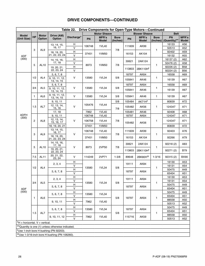
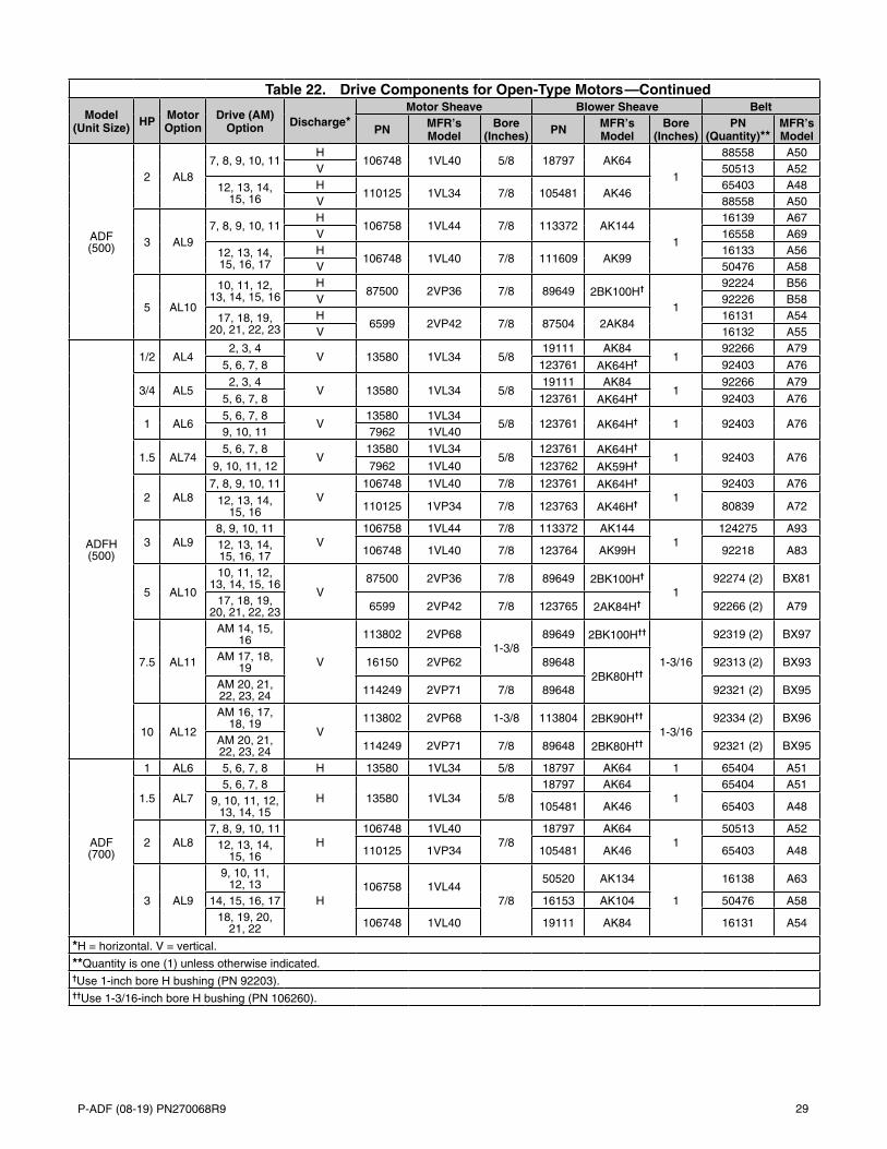
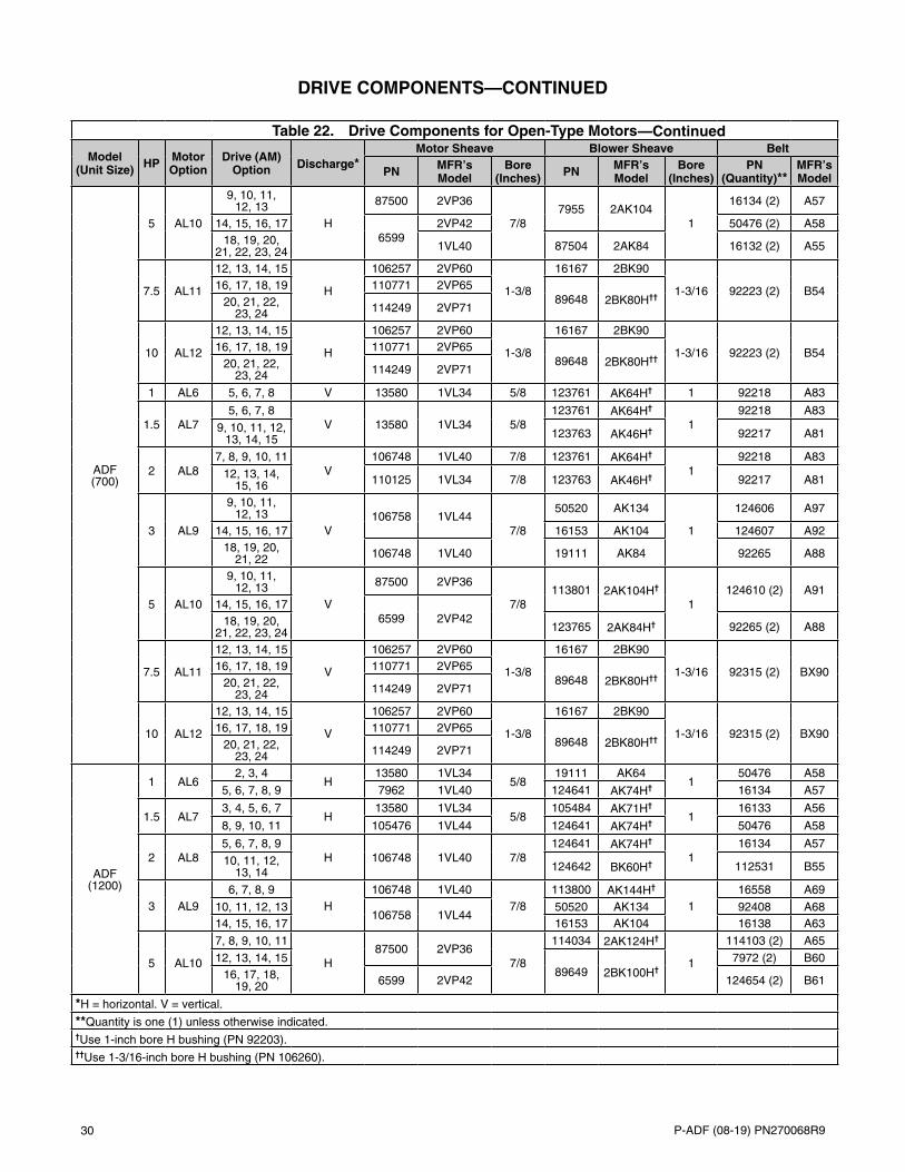
Table 22. Drive Components for Open-Type Motors
Model (Unit Size) HP Motor
OptionDrive (AM)
Option Discharge*Motor Sheave Blower Sheave Belt
PN MFR’s Model
Bore (Inches) PN MFR’s
ModelBore
(Inches)PN
(Quantity)**MFR’s Model
ADF (300)
1/2 AL45, 6, 7, 8
H 13580
1VL34 5/8
18797AK64
1
88558 A50V 13580 18797 50472 A45
9, 10, 11, 12, 13, 14, 15
H 13580 105841AK46
92402 A59V 13580 105841 50470 A43
3/4 AL55, 6, 7, 8
H 13580
1VL34 5/8
18797AK64
1
88558 A50V 13580 18797 50472 A45
9, 10, 11, 12, 13, 14, 15
H 13580 105481AK46
92402 A59V 13580 105481 50470 A43
1 AL6 9, 10, 11, 12, 13, 14, 15
H 135801VL34 5/8
105481AK46 1
92402 A59V 13580 105481 50470 A43
1.5 AL7
9, 10, 11H 105476
1VL445/8
105484AK71H†
1
16130 A53V 105476 105484 65403 A48
12, 13, 14, 15, 16
H 105476 105481
AK46
88558 A50V 105476 105481 50473 A46
17, 18H 7962
1VL40105481 65403 A48
V 7962 105481 52966 A44
2 AL8
9, 10, 11H 106748
1VL40
7/8
18797AK64
1
65404 A51V 106748 18797 50473 A46
12, 13, 14, 15, 16, 17
H 1067581VL44
105482
AK56
88558 A50V 106758 105482 50473 A46
18, 19, 20, 21H 37451
1VM50105482 88558 A50
V 37451 105482 50473 A46
*H = horizontal. V = vertical.
**Quantity is one (1) unless otherwise indicated.†Use 1-inch bore H bushing (PN 92203).
28 P-ADF (08-19) PN270068R9
Table 22. Drive Components for Open-Type Motors
Model (Unit Size) HP Motor
OptionDrive (AM)
Option Discharge*Motor Sheave Blower Sheave Belt
PN MFR’s Model
Bore (Inches) PN MFR’s
ModelBore
(Inches)PN
(Quantity)**MFR’s Model
ADF (300)
3 AL9
13, 14, 15, 16, 17
H106748 1VL40
7/8111609 AK99
1
16133 A56V 50513 A52
18, 19, 20, 21, 22, 23, 24
H37451 1VM50 16153 AK104
92402 A59V 16132 A55
5 AL10
14, 15, 16, 17, 18
H
8973 1VM50 7/830621 2AK124
1
16137 (2) A62V 50476 (2) A58
19, 20, 21, 22, 23, 24
H113803 2BK110H† 92226 (2) B58
V 92224 (2) B56
ADFH (300)
1/2 AL45, 6, 7, 8
V 13580 1VL34 5/818797 AK64
116558 A69
9, 10, 11, 12, 13, 14, 15 105841 AK46 16139 A67
3/4 AL55, 6, 7, 8
V 13580 1VL34 5/818797 AK64
116558 A69
9, 10, 11, 12, 13, 14, 15 105841 AK46 16139 A67
1 AL6 9, 10, 11, 12, 13, 14, 15 V 13580 1VL34 5/8 105841 AK46 1 16139 A67
1.5 AL7
9, 10, 11
V105476 1VL44
5/8 105484 AK71H†
1
80839 A72
12, 13, 14, 15, 16 7/8
105482 AK56 124347 A71
17, 18 7962 1VL40 105481 AK46 92408 A68
2 AL8
9, 10, 11
V
106748 1VL40
7/8
18797 AK64
1
124347 A7112, 13, 14, 15, 16, 17 106758 1VL44
105482 AK56124347 A71
18, 19, 20, 21 37451 1VM50 80839 A72
3 AL9
13, 14, 15, 16, 17
V106748 1VL40
7/8111609 AK99
192403 A76
18, 19, 20, 21, 22, 23, 24 37451 1VM50 16153 AK104 92266 A79
5 AL10
14, 15, 16, 17, 18
V 8973 2VP50 7/830621 2AK124
192218 (2) A83
19, 20, 21, 22, 23, 24 113803 2BK110H† 92271 (2) B79
7.5 AL11 20, 21, 22, 23, 24 V 114249 2VP71 1-3/8 89648 2BK80H†† 1-3/16 92315 (2) BX90
ADF (500)
1/2 AL42, 3, 4
H
13580 1VL34 5/819111 AK84
1
16130 A53V 16131 A54
5, 6, 7, 8H
18797 AK6450475 A49
V 65404 A51
3/4 AL52, 3, 4
H
13580 1VL34 5/819111 AK84
1
16130 A53V 16131 A54
5, 6, 7, 8H
18797 AK6450475 A49
V 65404 A51
1 AL65, 6, 7, 8
H13580 1VL34
5/8 18797 AK64 1
50475 A49V 65404 A51
9, 10, 11H
7962 1VL4088558 A50
V 50513 A52
1.5 AL75, 6, 7, 8
H13580 1VL34
5/818797 AK64
1
50475 A49V 65404 A51
9, 10, 11, 12H
7962 1VL40 115716 AK5988558 A50
V 50513 A52
*H = horizontal. V = vertical.
**Quantity is one (1) unless otherwise indicated.†Use 1-inch bore H bushing (PN 92203).††Use 1-3/16-inch bore H bushing (PN 106260).
DRIVE COMPONENTS—CONTINUED
—Continued
P-ADF (08-19) PN270068R9 29
Table 22. Drive Components for Open-Type Motors
Model (Unit Size) HP Motor
OptionDrive (AM)
Option Discharge*Motor Sheave Blower Sheave Belt
PN MFR’s Model
Bore (Inches) PN MFR’s
ModelBore
(Inches)PN
(Quantity)**MFR’s Model
ADF (500)
2 AL87, 8, 9, 10, 11
H106748 1VL40 5/8 18797 AK64
1
88558 A50V 50513 A52
12, 13, 14, 15, 16
H110125 1VL34 7/8 105481 AK46
65403 A48V 88558 A50
3 AL97, 8, 9, 10, 11
H106758 1VL44 7/8 113372 AK144
1
16139 A67V 16558 A69
12, 13, 14, 15, 16, 17
H106748 1VL40 7/8 111609 AK99
16133 A56V 50476 A58
5 AL10
10, 11, 12, 13, 14, 15, 16
H87500 2VP36 7/8 89649 2BK100H†
1
92224 B56V 92226 B58
17, 18, 19, 20, 21, 22, 23
H6599 2VP42 7/8 87504 2AK84
16131 A54V 16132 A55
ADFH (500)
1/2 AL42, 3, 4
V 13580 1VL34 5/819111 AK84
192266 A79
5, 6, 7, 8 123761 AK64H† 92403 A76
3/4 AL52, 3, 4
V 13580 1VL34 5/819111 AK84
192266 A79
5, 6, 7, 8 123761 AK64H† 92403 A76
1 AL65, 6, 7, 8
V13580 1VL34
5/8 123761 AK64H† 1 92403 A769, 10, 11 7962 1VL40
1.5 AL745, 6, 7, 8
V13580 1VL34
5/8123761 AK64H†
1 92403 A769, 10, 11, 12 7962 1VL40 123762 AK59H†
2 AL87, 8, 9, 10, 11
V106748 1VL40 7/8 123761 AK64H†
192403 A76
12, 13, 14, 15, 16 110125 1VP34 7/8 123763 AK46H† 80839 A72
3 AL98, 9, 10, 11
V106758 1VL44 7/8 113372 AK144
1124275 A93
12, 13, 14, 15, 16, 17 106748 1VL40 7/8 123764 AK99H 92218 A83
5 AL10
10, 11, 12, 13, 14, 15, 16
V87500 2VP36 7/8 89649 2BK100H†
192274 (2) BX81
17, 18, 19, 20, 21, 22, 23 6599 2VP42 7/8 123765 2AK84H† 92266 (2) A79
7.5 AL11
AM 14, 15, 16
V
113802 2VP681-3/8
89649 2BK100H††
1-3/16
92319 (2) BX97
AM 17, 18, 19 16150 2VP62 89648
2BK80H††92313 (2) BX93
AM 20, 21, 22, 23, 24 114249 2VP71 7/8 89648 92321 (2) BX95
10 AL12
AM 16, 17, 18, 19
V113802 2VP68 1-3/8 113804 2BK90H††
1-3/1692334 (2) BX96
AM 20, 21, 22, 23, 24 114249 2VP71 7/8 89648 2BK80H†† 92321 (2) BX95
ADF (700)
1 AL6 5, 6, 7, 8 H 13580 1VL34 5/8 18797 AK64 1 65404 A51
1.5 AL75, 6, 7, 8
H 13580 1VL34 5/818797 AK64
165404 A51
9, 10, 11, 12, 13, 14, 15 105481 AK46 65403 A48
2 AL87, 8, 9, 10, 11
H106748 1VL40
7/818797 AK64
150513 A52
12, 13, 14, 15, 16 110125 1VP34 105481 AK46 65403 A48
3 AL9
9, 10, 11, 12, 13
H106758 1VL44
7/8
50520 AK134
1
16138 A63
14, 15, 16, 17 16153 AK104 50476 A5818, 19, 20,
21, 22 106748 1VL40 19111 AK84 16131 A54
*H = horizontal. V = vertical.
**Quantity is one (1) unless otherwise indicated.†Use 1-inch bore H bushing (PN 92203).††Use 1-3/16-inch bore H bushing (PN 106260).
—Continued
30 P-ADF (08-19) PN270068R9
Table 22. Drive Components for Open-Type Motors
Model (Unit Size) HP Motor
OptionDrive (AM)
Option Discharge*Motor Sheave Blower Sheave Belt
PN MFR’s Model
Bore (Inches) PN MFR’s
ModelBore
(Inches)PN
(Quantity)**MFR’s Model
ADF (700)
5 AL10
9, 10, 11, 12, 13
H
87500 2VP36
7/87955 2AK104
1
16134 (2) A57
14, 15, 16, 176599
2VP42 50476 (2) A5818, 19, 20,
21, 22, 23, 24 1VL40 87504 2AK84 16132 (2) A55
7.5 AL11
12, 13, 14, 15
H
106257 2VP60
1-3/8
16167 2BK90
1-3/16 92223 (2) B5416, 17, 18, 19 110771 2VP6589648 2BK80H††20, 21, 22,
23, 24 114249 2VP71
10 AL12
12, 13, 14, 15
H
106257 2VP60
1-3/8
16167 2BK90
1-3/16 92223 (2) B5416, 17, 18, 19 110771 2VP6589648 2BK80H††20, 21, 22,
23, 24 114249 2VP71
1 AL6 5, 6, 7, 8 V 13580 1VL34 5/8 123761 AK64H† 1 92218 A83
1.5 AL75, 6, 7, 8
V 13580 1VL34 5/8123761 AK64H†
192218 A83
9, 10, 11, 12, 13, 14, 15 123763 AK46H† 92217 A81
2 AL87, 8, 9, 10, 11
V106748 1VL40 7/8 123761 AK64H†
192218 A83
12, 13, 14, 15, 16 110125 1VL34 7/8 123763 AK46H† 92217 A81
3 AL9
9, 10, 11, 12, 13
V106758 1VL44
7/8
50520 AK134
1
124606 A97
14, 15, 16, 17 16153 AK104 124607 A9218, 19, 20,
21, 22 106748 1VL40 19111 AK84 92265 A88
5 AL10
9, 10, 11, 12, 13
V
87500 2VP36
7/8113801 2AK104H†
1124610 (2) A91
14, 15, 16, 176599 2VP4218, 19, 20,
21, 22, 23, 24 123765 2AK84H† 92265 (2) A88
7.5 AL11
12, 13, 14, 15
V
106257 2VP60
1-3/8
16167 2BK90
1-3/16 92315 (2) BX9016, 17, 18, 19 110771 2VP6589648 2BK80H††20, 21, 22,
23, 24 114249 2VP71
10 AL12
12, 13, 14, 15
V
106257 2VP60
1-3/8
16167 2BK90
1-3/16 92315 (2) BX9016, 17, 18, 19 110771 2VP6589648 2BK80H††20, 21, 22,
23, 24 114249 2VP71
ADF (1200)
1 AL62, 3, 4
H13580 1VL34
5/819111 AK64
150476 A58
5, 6, 7, 8, 9 7962 1VL40 124641 AK74H† 16134 A57
1.5 AL73, 4, 5, 6, 7
H13580 1VL34
5/8105484 AK71H†
116133 A56
8, 9, 10, 11 105476 1VL44 124641 AK74H† 50476 A58
2 AL85, 6, 7, 8, 9
H 106748 1VL40 7/8124641 AK74H†
116134 A57
10, 11, 12, 13, 14 124642 BK60H† 112531 B55
3 AL96, 7, 8, 9
H106748 1VL40
7/8113800 AK144H†
116558 A69
10, 11, 12, 13106758 1VL44
50520 AK134 92408 A6814, 15, 16, 17 16153 AK104 16138 A63
5 AL10
7, 8, 9, 10, 11
H87500 2VP36
7/8
114034 2AK124H†
1
114103 (2) A65
12, 13, 14, 1589649 2BK100H†
7972 (2) B6016, 17, 18,
19, 20 6599 2VP42 124654 (2) B61
*H = horizontal. V = vertical.
**Quantity is one (1) unless otherwise indicated.†Use 1-inch bore H bushing (PN 92203).††Use 1-3/16-inch bore H bushing (PN 106260).
DRIVE COMPONENTS—CONTINUED
—Continued
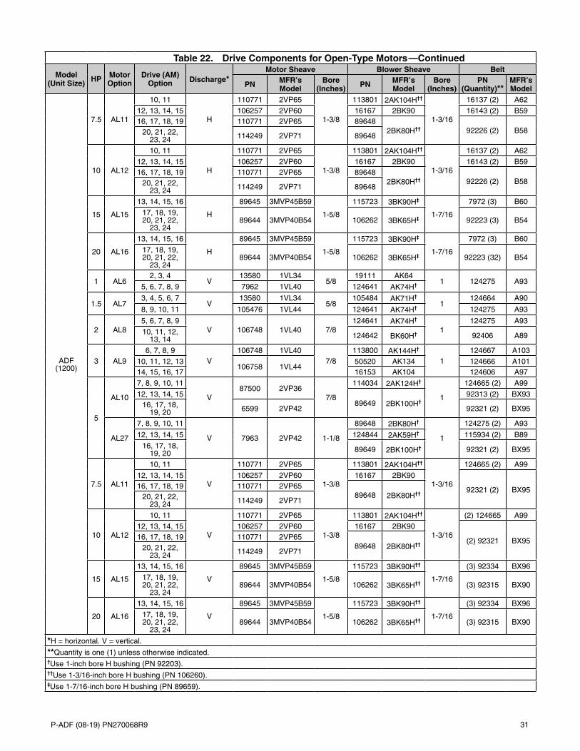
P-ADF (08-19) PN270068R9 31
Table 22. Drive Components for Open-Type Motors
Model (Unit Size) HP Motor
OptionDrive (AM)
Option Discharge*Motor Sheave Blower Sheave Belt
PN MFR’s Model
Bore (Inches) PN MFR’s
ModelBore
(Inches)PN
(Quantity)**MFR’s Model
ADF (1200)
7.5 AL11
10, 11
H
110771 2VP65
1-3/8
113801 2AK104H††
1-3/16
16137 (2) A62
12, 13, 14, 15 106257 2VP60 16167 2BK90 16143 (2) B5916, 17, 18, 19 110771 2VP65 89648
2BK80H†† 92226 (2) B5820, 21, 22, 23, 24 114249 2VP71 89648
10 AL12
10, 11
H
110771 2VP65
1-3/8
113801 2AK104H††
1-3/16
16137 (2) A62
12, 13, 14, 15 106257 2VP60 16167 2BK90 16143 (2) B5916, 17, 18, 19 110771 2VP65 89648
2BK80H†† 92226 (2) B5820, 21, 22, 23, 24 114249 2VP71 89648
15 AL15
13, 14, 15, 16
H
89645 3MVP45B59
1-5/8
115723 3BK90H‡
1-7/16
7972 (3) B60
17, 18, 19, 20, 21, 22,
23, 2489644 3MVP40B54 106262 3BK65H‡ 92223 (3) B54
20 AL16
13, 14, 15, 16
H
89645 3MVP45B59
1-5/8
115723 3BK90H‡
1-7/16
7972 (3) B60
17, 18, 19, 20, 21, 22,
23, 2489644 3MVP40B54 106262 3BK65H‡ 92223 (32) B54
1 AL6 2, 3, 4
V13580 1VL34
5/819111 AK64
1 124275 A935, 6, 7, 8, 9 7962 1VL40 124641 AK74H†
1.5 AL73, 4, 5, 6, 7
V13580 1VL34
5/8105484 AK71H†
1124664 A90
8, 9, 10, 11 105476 1VL44 124641 AK74H† 124275 A93
2 AL85, 6, 7, 8, 9
V 106748 1VL40 7/8124641 AK74H†
1124275 A93
10, 11, 12, 13, 14 124642 BK60H† 92406 A89
3 AL96, 7, 8, 9
V106748 1VL40
7/8113800 AK144H†
1124667 A103
10, 11, 12, 13106758 1VL44
50520 AK134 124666 A10114, 15, 16, 17 16153 AK104 124606 A97
5
AL10
7, 8, 9, 10, 11
V87500 2VP36
7/8
114034 2AK124H†
1
124665 (2) A99
12, 13, 14, 1589649 2BK100H†
92313 (2) BX9316, 17, 18,
19, 20 6599 2VP42 92321 (2) BX95
AL27
7, 8, 9, 10, 11
V 7963 2VP42 1-1/8
89648 2BK80H†
1
124275 (2) A93
12, 13, 14, 15 124844 2AK59H† 115934 (2) B89
16, 17, 18, 19, 20 89649 2BK100H† 92321 (2) BX95
7.5 AL11
10, 11
V
110771 2VP65
1-3/8
113801 2AK104H††
1-3/16
124665 (2) A99
12, 13, 14, 15 106257 2VP60 16167 2BK90
92321 (2) BX9516, 17, 18, 19 110771 2VP6589648 2BK80H††20, 21, 22,
23, 24 114249 2VP71
10 AL12
10, 11
V
110771 2VP65
1-3/8
113801 2AK104H††
1-3/16
(2) 124665 A99
12, 13, 14, 15 106257 2VP60 16167 2BK90
(2) 92321 BX9516, 17, 18, 19 110771 2VP6589648 2BK80H††20, 21, 22,
23, 24 114249 2VP71
15 AL15
13, 14, 15, 16
V
89645 3MVP45B59
1-5/8
115723 3BK90H††
1-7/16
(3) 92334 BX96
17, 18, 19, 20, 21, 22,
23, 2489644 3MVP40B54 106262 3BK65H†† (3) 92315 BX90
20 AL16
13, 14, 15, 16
V
89645 3MVP45B59
1-5/8
115723 3BK90H††
1-7/16
(3) 92334 BX96
17, 18, 19, 20, 21, 22,
23, 2489644 3MVP40B54 106262 3BK65H†† (3) 92315 BX90
*H = horizontal. V = vertical.
**Quantity is one (1) unless otherwise indicated.†Use 1-inch bore H bushing (PN 92203).††Use 1-3/16-inch bore H bushing (PN 106260).‡Use 1-7/16-inch bore H bushing (PN 89659).
—Continued
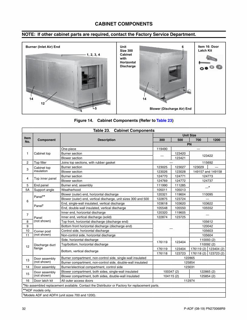
32 P-ADF (08-19) PN270068R9
CABINET COMPONENTS
NOTE: If other cabinet parts are required, contact the Factory Service Department.
Figure 14. Cabinet Components (Refer to Table 23)
Unit Size 300 Cabinet with Horizontal Discharge
Burner (Inlet Air) End
1, 2, 3, 4
5
6
1412
14
Item 16: Door Latch Kit
Blower (Discharge Air) End
Table 23. Cabinet Components
Item No. Component Description
Unit Size300 500 700 1200
PN
1 Cabinet topOne-piece 119490 —Burner section
—123420
123422Blower section 123421
2 Top filler Joins top sections, with rubber gasket — 115692
3 Cabinet top insulation
Burner section 123025 123027 123029 —Blower section 123026 123028 149157 and 149158
4 Top inner panelBurner section 124770 124771 124773Blower section 124769 124772 124737
5 End panel Burner end, assembly 111990 111285—*
5A Support angle Weatherhood 105011 105013
6Panel**
Blower (outer) end, horizontal discharge 120321 119604 110095Blower (outer) end, vertical discharge, unit sizes 300 and 500 122875 123724 —
Panel†End, single-wall insulated, vertical discharge 103618 103620 103622End, double-wall insulated, vertical discharge 105548 105550 105552
7Panel (not shown)
Inner end, horizontal discharge 120320 119605—
Inner end, vertical discharge (solid) 122874 1237258 Top front, horizontal discharge (discharge end)
—
1056129 Bottom front horizontal discharge (discharge end) 120042
10 Corner post (not shown)
Control side, horizontal discharge 10560311 Non-control side, horizontal discharge 105604
12 Discharge duct flange
Side, horizontal discharge176119 123404
110093 (2)Top/bottom, horizontal discharge 110092 (2)
Bottom, vertical discharge176119 123404 176119 (2) 123404 (2)176118 123723 176118 (2) 123723 (2)
13 Door assembly (not shown)
Burner compartment, non-control side, single-wall insulated 122865Burner compartment, non-control side, double-wall insulated 125854
14 Door assembly Burner/electrical compartment, control side 123031
15 Door assembly (not shown)
Blower compartment, both sides, single-wall insulated 100347 (2) 122865 (2)Blower compartment, both sides, double-wall insulated 104115 (2) 125854 (2)
16 Door latch kit All outer access doors 112974
*No assembled replacement available. Contact the Distributor or Factory for replacement parts.
**ADF models only.†Models ADF and ADFH (unit sizes 700 and 1200).
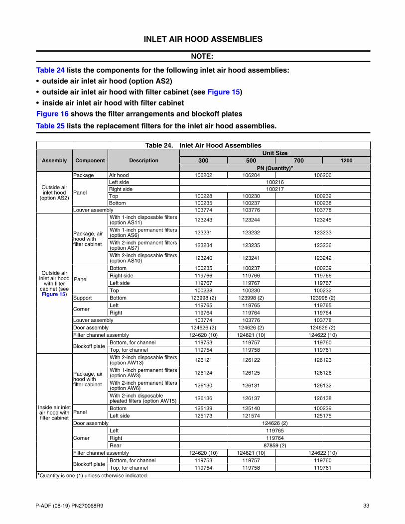
P-ADF (08-19) PN270068R9 33
INLET AIR HOOD ASSEMBLIES
NOTE:
Table 24 lists the components for the following inlet air hood assemblies:
• outside air inlet air hood (option AS2)
• outside air inlet air hood with filter cabinet (see Figure 15)
• inside air inlet air hood with filter cabinet
Figure 16 shows the filter arrangements and blockoff plates
Table 25 lists the replacement filters for the inlet air hood assemblies.
Table 24. Inlet Air Hood Assemblies
Assembly Component DescriptionUnit Size
300 500 700 1200PN (Quantity)*
Outside air inlet hood
(option AS2)
Package Air hood 106202 106204 106206
Panel
Left side 100216Right side 100217Top 100228 100230 100232Bottom 100235 100237 100238
Louver assembly 103774 103776 103778
Outside air inlet air hood
with filter cabinet (see Figure 15)
Package, air hood with filter cabinet
With 1-inch disposable filters (option AS11) 123243 123244 123245
With 1-inch permanent filters (option AS6) 123231 123232 123233
With 2-inch permanent filters (option AS7) 123234 123235 123236
With 2-inch disposable filters (option AS10) 123240 123241 123242
Panel
Bottom 100235 100237 100239Right side 119766 119766 119766Left side 119767 119767 119767Top 100228 100230 100232
Support Bottom 123998 (2) 123998 (2) 123998 (2)
CornerLeft 119765 119765 119765Right 119764 119764 119764
Louver assembly 103774 103776 103778Door assembly 124626 (2) 124626 (2) 124626 (2)Filter channel assembly 124620 (10) 124621 (10) 124622 (10)
Blockoff plateBottom, for channel 119753 119757 119760Top, for channel 119754 119758 119761
Inside air inlet air hood with filter cabinet
Package, air hood with filter cabinet
With 2-inch disposable filters (option AW13) 126121 126122 126123
With 1-inch permanent filters (option AW3) 126124 126125 126126
With 2-inch permanent filters (option AW6) 126130 126131 126132
With 2-inch disposable pleated filters (option AW15) 126136 126137 126138
PanelBottom 125139 125140 100239Left side 125173 121574 125175
Door assembly 124626 (2)
CornerLeft 119765Right 119764Rear 87859 (2)
Filter channel assembly 124620 (10) 124621 (10) 124622 (10)
Blockoff plateBottom, for channel 119753 119757 119760Top, for channel 119754 119758 119761
*Quantity is one (1) unless otherwise indicated.
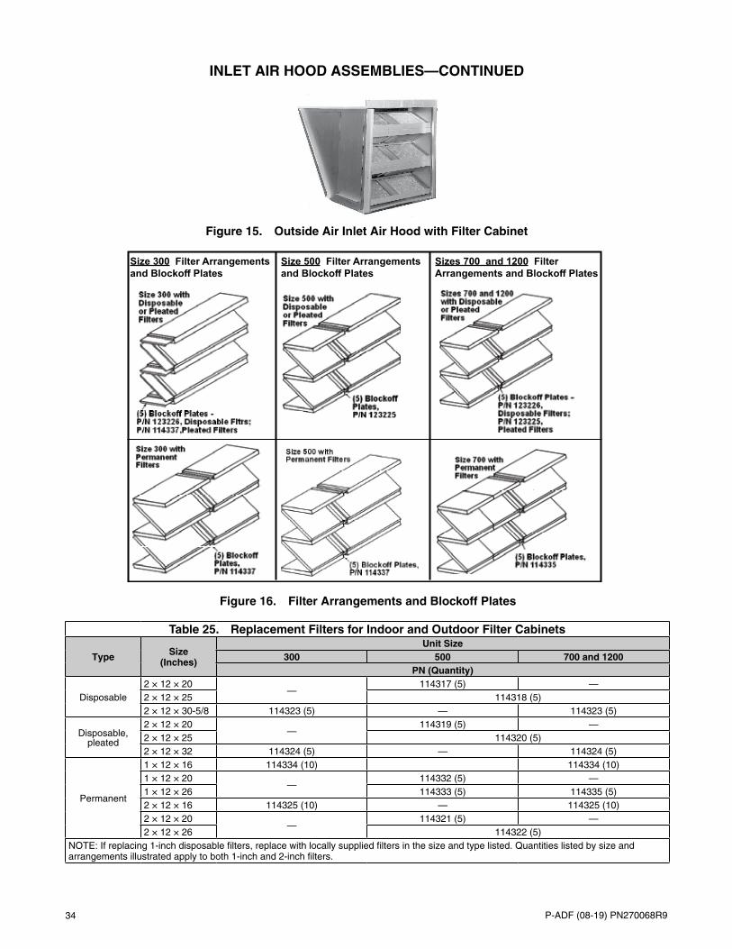
34 P-ADF (08-19) PN270068R9
Figure 15. Outside Air Inlet Air Hood with Filter Cabinet
Size 300 Filter Arrangements and
Size 500 Filter Arrangements Sizes 700 and 1200 Filter
Figure 16. Filter Arrangements and Blockoff Plates
Table 25. Replacement Filters for Indoor and Outdoor Filter Cabinets
Type Size (Inches)
Unit Size300 500 700 and 1200
PN (Quantity)
Disposable2 × 12 × 20
—114317 (5) —
2 × 12 × 25 114318 (5)2 × 12 × 30-5/8 114323 (5) — 114323 (5)
Disposable, pleated
2 × 12 × 20—
114319 (5) —2 × 12 × 25 114320 (5)2 × 12 × 32 114324 (5) — 114324 (5)
Permanent
1 × 12 × 16 114334 (10) 114334 (10)1 × 12 × 20
—114332 (5) —
1 × 12 × 26 114333 (5) 114335 (5)2 × 12 × 16 114325 (10) — 114325 (10)2 × 12 × 20
—114321 (5) —
2 × 12 × 26 114322 (5)NOTE: If replacing 1-inch disposable filters, replace with locally supplied filters in the size and type listed. Quantities listed by size and arrangements illustrated apply to both 1-inch and 2-inch filters.
INLET AIR HOOD ASSEMBLIES—CONTINUED
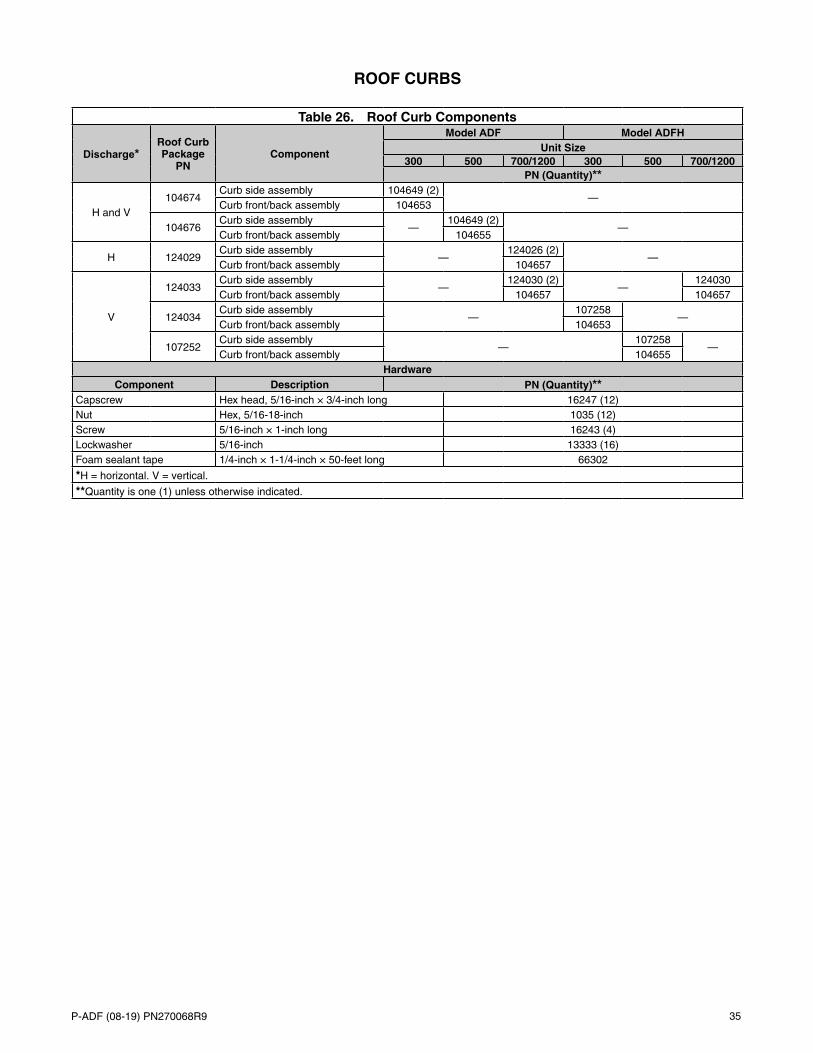
P-ADF (08-19) PN270068R9 35
ROOF CURBS
Table 26. Roof Curb Components
Discharge*Roof Curb Package
PNComponent
Model ADF Model ADFHUnit Size
300 500 700/1200 300 500 700/1200PN (Quantity)**
H and V104674
Curb side assembly 104649 (2)—
Curb front/back assembly 104653
104676Curb side assembly
—104649 (2)
—Curb front/back assembly 104655
H 124029Curb side assembly
—124026 (2)
—Curb front/back assembly 104657
V
124033Curb side assembly
—124030 (2)
—124030
Curb front/back assembly 104657 104657
124034Curb side assembly
—107258
—Curb front/back assembly 104653
107252Curb side assembly
—107258
—Curb front/back assembly 104655
HardwareComponent Description PN (Quantity)**
Capscrew Hex head, 5/16-inch × 3/4-inch long 16247 (12)Nut Hex, 5/16-18-inch 1035 (12)Screw 5/16-inch × 1-inch long 16243 (4)Lockwasher 5/16-inch 13333 (16)Foam sealant tape 1/4-inch × 1-1/4-inch × 50-feet long 66302
*H = horizontal. V = vertical.
**Quantity is one (1) unless otherwise indicated.

Specifications and illustrations subject to change without notice or incurring obligations.©2019 Nortek Global HVAC LLC, O’Fallon, MO.All rights reserved.P-ADF (08-19) PN270068R9
AG
ENCY PROCESS
STA
RT-
UP
PRODUCT
CUSTO
MER
WARRANTY
CONVERGENT
QUALITY SYSTEM
CQSQ M
CQS


![[ A ] SPIRITS ADF [ADF] VODKA - BASICabc.utah.gov/products/documents/CategoryPriceList.pdf · [ a ] spirits adf [adf] vodka - basic 037993 200 48 smirnoff vodka 200ml adw 1 0.81 5.49](https://img.pdfslide.us/doc/110x75/5b1b4d4d7f8b9a28258e6b02/-a-spirits-adf-adf-vodka-a-spirits-adf-adf-vodka-basic-037993.jpg)