Embed Size (px)
Citation preview
Replacement of Botlek Lifting Bridge, Motorway A15, Netherlands
Robert SCHEDLER Structural Engineer, CEO VCE ZT GmbH Vienna, Austria [email protected] Robert Schedler, born 1966, received his civil engineering degree from the Technical Univ. of Vienna. He started to work for VCE in 1992 and become CEO in 1999. His main activity is the infrastructure sector.
Ulrich EDER Project Director VCE ZT GmbH Vienna, Austria [email protected] Ulrich Eder, born 1977, received his civil engineering degree from the Technical Univ. of Vienna. He started to work for VCE in 2003 and become leader of the bridge competence center in 2008.
Erik JILLE Design Manager A-Lanes A15, Mobility vof Pernis, Netherlands [email protected] Erik Jille, born 1963, received his civil engineering degree from the Technical Univ. of Delft. As senior design manager for Strukton Engineering he has a wide experience in the field of infrastructural projects.
Summary
The new Botlek twin lifting bridge is one of the largest lifting bridges in the world and currently under construction as part of the new extended Motorway A15 from Vaanplein to Maasvlakte in the harbour of Rotterdam and part of the respective DBFM project. The bridge will accommodate two navigation channels of approximately 90 m each, and provide a vertical clearance of 14,60 m for crossing road and rail traffic and a lifted clearance of 45,60 m for large ship traffic. The lifting time for the 5.000 to lifting weight per deck is limited to 90 seconds and requires a fully balanced lifting system. The subject of this paper will focus on the bridge functionality, the design requirements, the interaction between railway and roadway actions, lifting requirements, the dimensioning of the massive concrete foundations of approx. 60 m length, 16 m width and 30 m height and the approx. 100 m long and 50 m wide three steel truss girder lifting elements.
Keywords: Lifting bridge, motorway and railway bridge, steel deck, balanced lifting system, counterweight, towers, underwater concrete, hydration heat, mass concrete.
1. Introduction
The new Botlek Bridge (see Figure 1, Fig. 2 and Fig. 3) crosses de Oude Maas and will replace the existing Botlek Bridge. An increase in the traffic capacity is realized to accommodate the second Maasvlakte. The new bridge will be located adjacent to the existing Botlek Bridge. During construction it is necessary to maintain the flow of traffic across the existing structure. After completion and opening of the new bridge the old Botlek Bridge will be dismantled.
Fig. 1: New Botlek Bridge, closed position – image Quist Wintermans Architekten
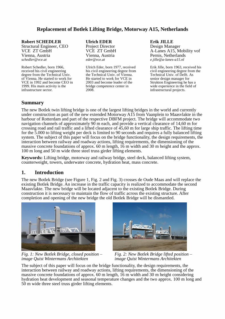
Fig. 2: New Botlek Bridge lifted position – image Quist Wintermans Architekten
The subject of this paper will focus on the bridge functionality, the design requirements, the interaction between railway and roadway actions, lifting requirements, the dimensioning of the massive concrete foundations of approx. 60 m length, 16 m width and 30 m height considering hydration heat development and seasonal temperature changes and the two approx. 100 m long and 50 m wide three steel truss girder lifting elements.
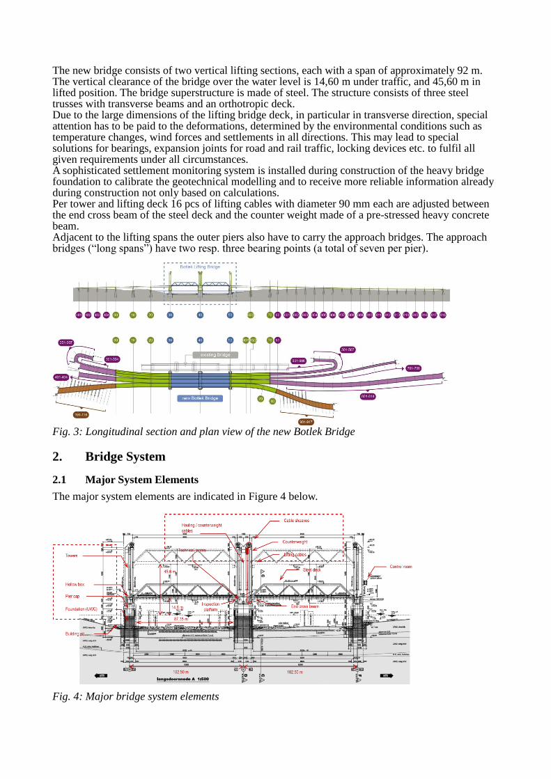
The new bridge consists of two vertical lifting sections, each with a span of approximately 92 m. The vertical clearance of the bridge over the water level is 14,60 m under traffic, and 45,60 m in lifted position. The bridge superstructure is made of steel. The structure consists of three steel trusses with transverse beams and an orthotropic deck. Due to the large dimensions of the lifting bridge deck, in particular in transverse direction, special attention has to be paid to the deformations, determined by the environmental conditions such as temperature changes, wind forces and settlements in all directions. This may lead to special solutions for bearings, expansion joints for road and rail traffic, locking devices etc. to fulfil all given requirements under all circumstances. A sophisticated settlement monitoring system is installed during construction of the heavy bridge foundation to calibrate the geotechnical modelling and to receive more reliable information already during construction not only based on calculations. Per tower and lifting deck 16 pcs of lifting cables with diameter 90 mm each are adjusted between the end cross beam of the steel deck and the counter weight made of a pre-stressed heavy concrete beam. Adjacent to the lifting spans the outer piers also have to carry the approach bridges. The approach bridges (“long spans”) have two resp. three bearing points (a total of seven per pier).
Fig. 3: Longitudinal section and plan view of the new Botlek Bridge
2. Bridge System
2.1 Major System Elements
The major system elements are indicated in Figure 4 below.
Fig. 4: Major bridge system elements
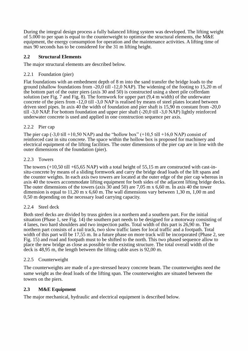
During the integral design process a fully balanced lifting system was developed. The lifting weight of 5.000 to per span is equal to the counterweight to optimise the structural elements, the M&E equipment, the energy consumption for operation and the maintenance activities. A lifting time of max 90 seconds has to be considered for the 31 m lifting height.
2.2 Structural Elements
The major structural elements are described below.
2.2.1 Foundation (pier)
Flat foundations with an embedment depth of 8 m into the sand transfer the bridge loads to the ground (shallow foundations from -20,0 till -12,0 NAP). The widening of the footing to 15,20 m of the bottom part of the outer piers (axis 30 and 50) is constructed using a sheet pile cofferdam solution (see Fig. 7 and Fig. 8). The formwork for upper part (9,4 m width) of the underwater concrete of the piers from -12,0 till -3,0 NAP is realised by means of steel plates located between driven steel pipes. In axis 40 the width of foundation and pier shaft is 15,90 m constant from -20,0 till -3,0 NAP. For bottom foundation and upper pier shaft (-20,0 till -3,0 NAP) lightly reinforced underwater concrete is used and applied in one construction sequence per axis.
2.2.2 Pier cap
The pier cap (-3,0 till +10,50 NAP) and the “hollow box” (+10,5 till +16,0 NAP) consist of reinforced cast in situ concrete. The space within the hollow box is proposed for machinery and electrical equipment of the lifting facilities. The outer dimensions of the pier cap are in line with the outer dimensions of the foundation (pier).
2.2.3 Towers
The towers (+10,50 till +65,65 NAP) with a total height of 55,15 m are constructed with cast-in-situ-concrete by means of a sliding formwork and carry the bridge dead loads of the lift spans and the counter weights. In each axis two towers are located at the outer edge of the pier cap whereas in axis 40 the towers accommodate lifting equipment for both sides of the adjacent lifting bridge decks. The outer dimensions of the towers (axis 30 and 50) are 7,05 m x 6,60 m. In axis 40 the tower dimension is equal to 11,20 m x 6,60 m. The wall dimensions vary between 1,30 m, 1,00 m and 0,50 m depending on the necessary load carrying capacity.
2.2.4 Steel deck
Both steel decks are divided by truss girders in a northern and a southern part. For the initial situation (Phase 1, see Fig. 14) the southern part needs to be designed for a motorway consisting of 4 lanes, two hard shoulders and two inspection paths. Total width of this part is 26,90 m. The northern part consists of a rail track, two slow traffic lanes for local traffic and a footpath. Total width of this part will be 17,55 m. In a future phase on more track will be incorporated (Phase 2, see Fig. 15) and road and footpath must to be shifted to the north. This two phased sequence allow to place the new bridge as close as possible to the existing structure. The total overall width of the deck is 48,95 m, the length between the lifting cable axes is 92,00 m.
2.2.5 Counterweight
The counterweights are made of a pre-stressed heavy concrete beam. The counterweights need the
same weight as the dead loads of the lifting span. The counterweights are situated between the
towers on the piers.
2.3 M&E Equipment
The major mechanical, hydraulic and electrical equipment is described below.
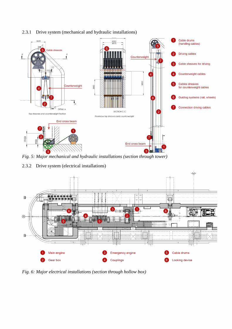
2.3.1 Drive system (mechanical and hydraulic installations)
Fig. 5: Major mechanical and hydraulic installations (section through tower)
2.3.2 Drive system (electrical installations)
Fig. 6: Major electrical installations (section through hollow box)
3. Structural Design Requirements
The design of the New Botlek Bridge is mainly based on following standards (amongst others):
NEN EN 1992-2: Eurocode 2: Design of concrete structures, Part 2: Concrete bridges NEN EN 1993-2: Eurocode 3: Design of steel structures; Part 2: Steel Bridges NEN EN 1993-1-9: Eurocode 3: Design of steel structures; Part 1-9: Fatigue NEN 6786: Rules for the design of moveable bridges OVS 00030: Ontwerpvoorschrift Kunstwerken
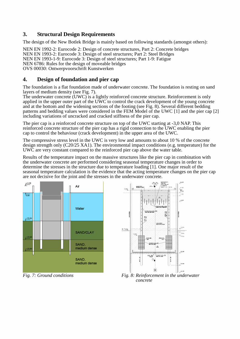
4. Design of foundation and pier cap
The foundation is a flat foundation made of underwater concrete. The foundation is resting on sand layers of medium density (see Fig. 7). The underwater concrete (UWC) is a lightly reinforced concrete structure. Reinforcement is only applied in the upper outer part of the UWC to control the crack development of the young concrete and at the bottom and the widening sections of the footing (see Fig. 8). Several different bedding patterns and bedding values were considered in the FEM Model of the UWC [1] and the pier cap [2] including variations of uncracked and cracked stiffness of the pier cap.
The pier cap is a reinforced concrete structure on top of the UWC starting at -3,0 NAP. This reinforced concrete structure of the pier cap has a rigid connection to the UWC enabling the pier cap to control the behaviour (crack development) in the upper area of the UWC.
The compressive stress level in the UWC is very low and amounts to about 10 % of the concrete design strength only (C20/25 XA1). The environmental impact conditions (e.g. temperature) for the UWC are very constant compared to the reinforced pier cap above the water table.
Results of the temperature impact on the massive structures like the pier cap in combination with the underwater concrete are performed considering seasonal temperature changes in order to determine the stresses in the structure due to temperature loading [1]. One major result of the seasonal temperature calculation is the evidence that the acting temperature changes on the pier cap are not decisive for the joint and the stresses in the underwater concrete.
Fig. 7: Ground conditions Fig. 8: Reinforcement in the underwater concrete
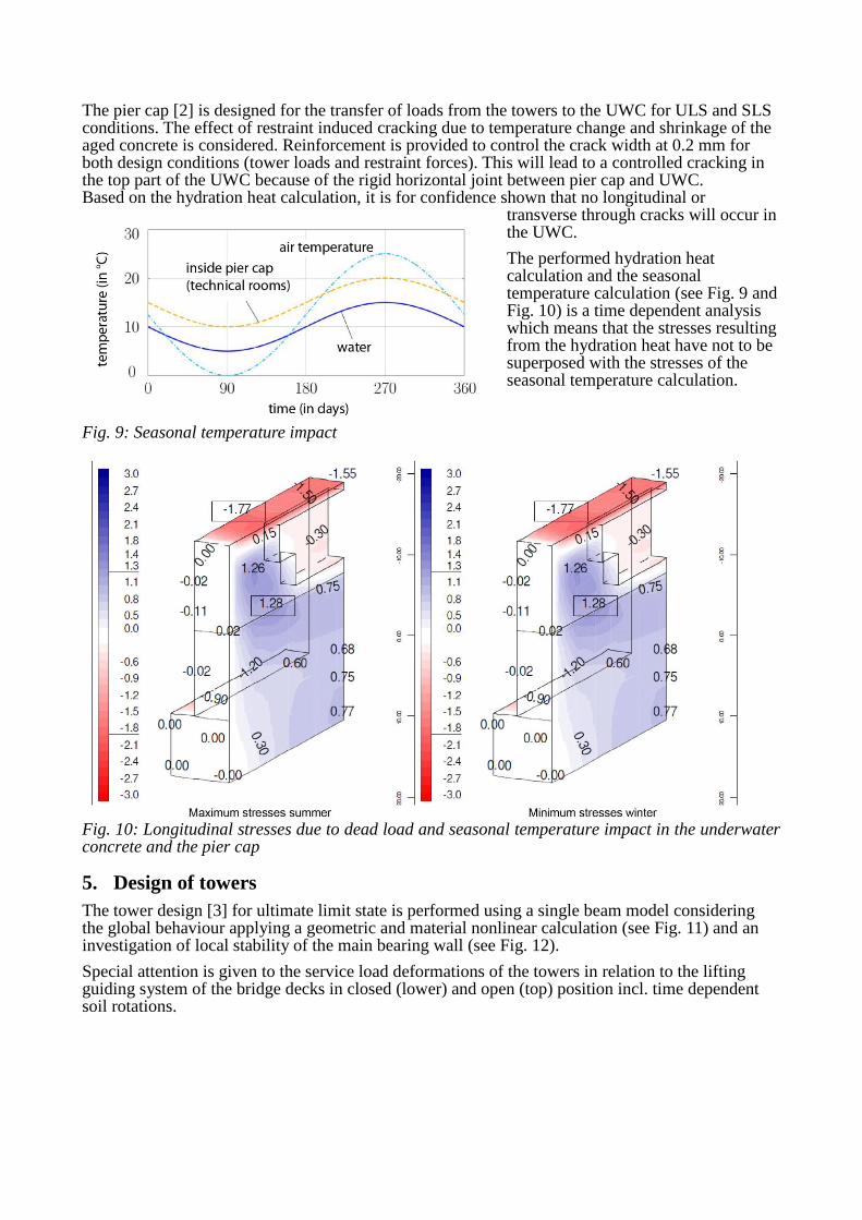
The pier cap [2] is designed for the transfer of loads from the towers to the UWC for ULS and SLS conditions. The effect of restraint induced cracking due to temperature change and shrinkage of the aged concrete is considered. Reinforcement is provided to control the crack width at 0.2 mm for both design conditions (tower loads and restraint forces). This will lead to a controlled cracking in the top part of the UWC because of the rigid horizontal joint between pier cap and UWC. Based on the hydration heat calculation, it is for confidence shown that no longitudinal or
transverse through cracks will occur in the UWC.
The performed hydration heat calculation and the seasonal temperature calculation (see Fig. 9 and Fig. 10) is a time dependent analysis which means that the stresses resulting from the hydration heat have not to be superposed with the stresses of the seasonal temperature calculation.
Fig. 9: Seasonal temperature impact
Fig. 10: Longitudinal stresses due to dead load and seasonal temperature impact in the underwater concrete and the pier cap
5. Design of towers
The tower design [3] for ultimate limit state is performed using a single beam model considering the global behaviour applying a geometric and material nonlinear calculation (see Fig. 11) and an investigation of local stability of the main bearing wall (see Fig. 12).
Special attention is given to the service load deformations of the towers in relation to the lifting guiding system of the bridge decks in closed (lower) and open (top) position incl. time dependent soil rotations.
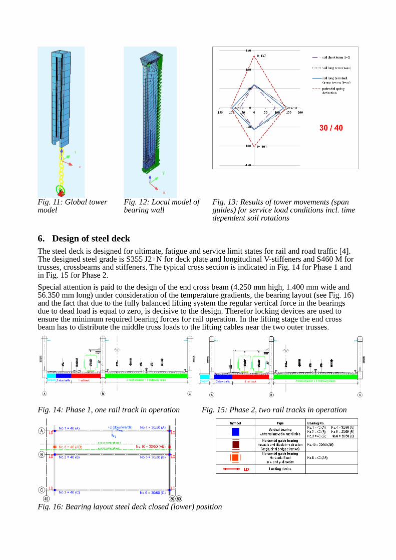
Fig. 11: Global tower model
Fig. 12: Local model of bearing wall
Fig. 13: Results of tower movements (span guides) for service load conditions incl. time dependent soil rotations
6. Design of steel deck
The steel deck is designed for ultimate, fatigue and service limit states for rail and road traffic [4]. The designed steel grade is S355 J2+N for deck plate and longitudinal V-stiffeners and S460 M for trusses, crossbeams and stiffeners. The typical cross section is indicated in Fig. 14 for Phase 1 and in Fig. 15 for Phase 2.
Special attention is paid to the design of the end cross beam (4.250 mm high, 1.400 mm wide and 56.350 mm long) under consideration of the temperature gradients, the bearing layout (see Fig. 16) and the fact that due to the fully balanced lifting system the regular vertical force in the bearings due to dead load is equal to zero, is decisive to the design. Therefor locking devices are used to ensure the minimum required bearing forces for rail operation. In the lifting stage the end cross beam has to distribute the middle truss loads to the lifting cables near the two outer trusses.
Fig. 14: Phase 1, one rail track in operation Fig. 15: Phase 2, two rail tracks in operation
Fig. 16: Bearing layout steel deck closed (lower) position
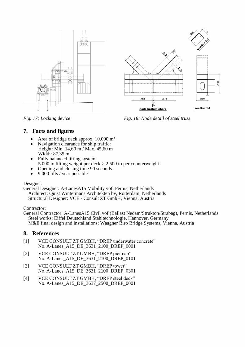
Fig. 17: Locking device Fig. 18: Node detail of steel truss
7. Facts and figures
Area of bridge deck approx. 10.000 m² Navigation clearance for ship traffic:
Height: Min. 14,60 m / Max. 45,60 m Width: 87,35 m
Fully balanced lifting system 5.000 to lifting weight per deck > 2.500 to per counterweight
Opening and closing time 90 seconds 9.000 lifts / year possible
Designer: General Designer: A-LanesA15 Mobility vof, Pernis, Netherlands Architect: Quist Wintermans Architekten bv, Rotterdam, Netherlands Structural Designer: VCE - Consult ZT GmbH, Vienna, Austria Contractor: General Contractor: A-LanesA15 Civil vof (Ballast Nedam/Strukton/Strabag), Pernis, Netherlands Steel works: Eiffel Deutschland Stahltechnologie, Hannover, Germany M&E final design and installations: Waagner Biro Bridge Systems, Vienna, Austria
8. References
[1] VCE CONSULT ZT GMBH, “DREP underwater concrete” No. A-Lanes_A15_DE_3631_2100_DREP_0001
[2] VCE CONSULT ZT GMBH, “DREP pier cap” No. A-Lanes_A15_DE_3631_2100_DREP_0101
[3] VCE CONSULT ZT GMBH, “DREP tower” No. A-Lanes_A15_DE_3631_2100_DREP_0301
[4] VCE CONSULT ZT GMBH, “DREP steel deck” No. A-Lanes_A15_DE_3637_2500_DREP_0001