Embed Size (px)
Citation preview
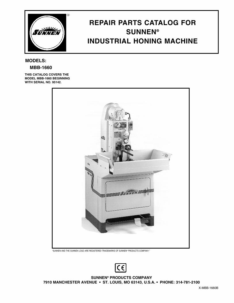
REPAIR PARTS CATALOG FORSUNNEN®
INDUSTRIAL HONING MACHINE
X-MBB-1660B
SUNNEN® PRODUCTS COMPANY7910 MANCHESTER AVENUE • ST. LOUIS, MO 63143, U.S.A. • PHONE: 314-781-2100
MODELS:
MBB-1660THIS CATALOG COVERS THEMODEL MBB-1660 BEGINNINGWITH SERIAL NO. 95142.
“SUNNEN AND THE SUNNEN LOGO ARE REGISTERED TRADEMARKS OF SUNNEN® PRODUCTS COMPANY.”
Like any machinery, this equipment maybe dangerous if used improperly. Besure to read and follow instructions foroperation of equipment.
iii
INTRODUCTIONIllustrations show all major components in exploded detail. Item numbers on each illustration are keyed tothe corresponding parts list, providing a descriptive identification of each part.
The parts lists include assemblies as well as detail parts. An item listed without a part number can beobtained as a component of the complete assembly of which it is a part.
Standard hardware items are listed with complete descriptions, such as Item 29 below. These may bepurchased at your local hardware store, but it is important to replace an item with one having the samedimensions as the original. In some places brand names and part numbers are shown. These may changedepending upon availability.
Sunnen® Products Company reserves the right to make changes, without notice, to materials,specifications, colors, designs and accessories included with units.
HOW TO ORDERWhen ordering replacement parts be sure to include the following information to ensure prompt shipment ofcorrect parts:
1. The part number and description of each part desired, obtained from this parts catalog.
2. The quantity of each part desired.
3. The voltage, frequency and phase, when ordering electrical parts.
4. The model and serial number of the machine, obtained from the name plate, where there is any questionconcerning a part.
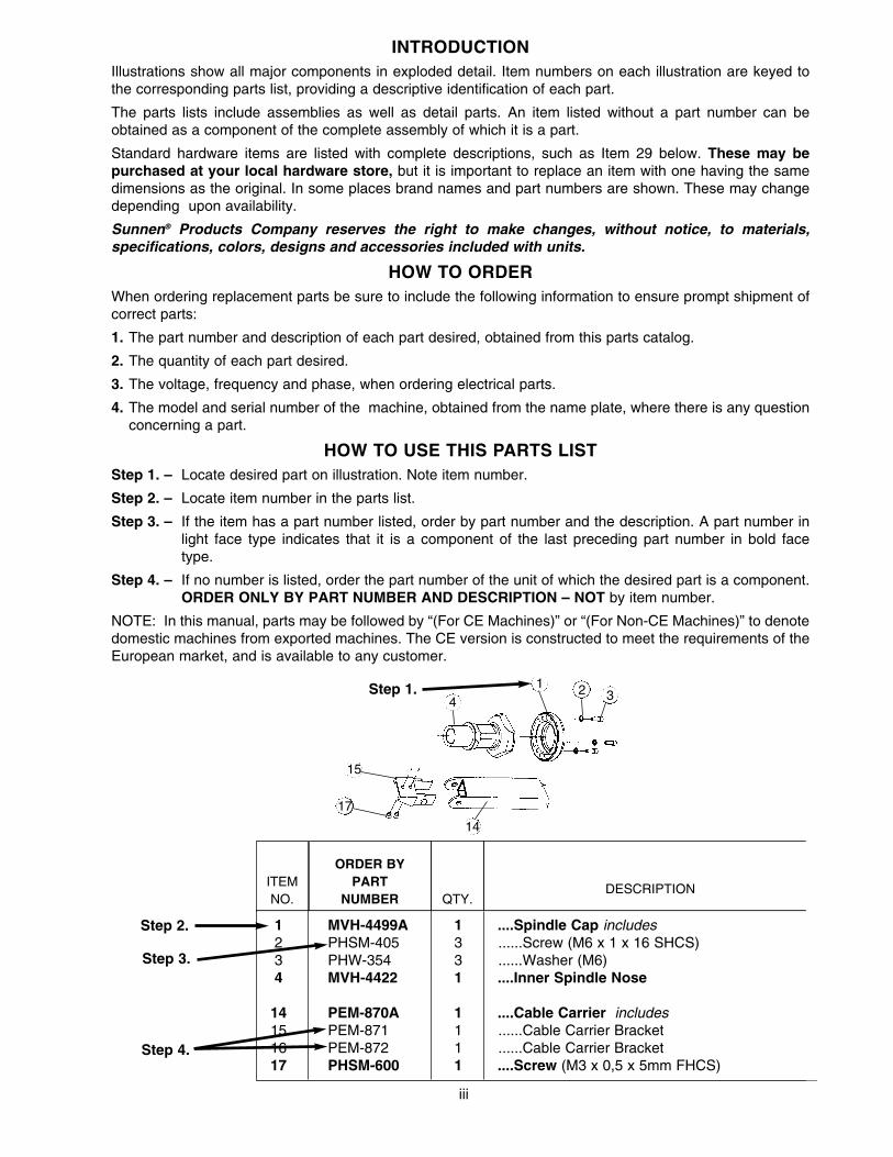
HOW TO USE THIS PARTS LISTStep 1. – Locate desired part on illustration. Note item number.
Step 2. – Locate item number in the parts list.
Step 3. – If the item has a part number listed, order by part number and the description. A part number in light face type indicates that it is a component of the last preceding part number in bold face type.
Step 4. – If no number is listed, order the part number of the unit of which the desired part is a component.ORDER ONLY BY PART NUMBER AND DESCRIPTION – NOT by item number.
NOTE: In this manual, parts may be followed by “(For CE Machines)” or “(For Non-CE Machines)” to denotedomestic machines from exported machines. The CE version is constructed to meet the requirements of theEuropean market, and is available to any customer.
ITEMNO.
ORDER BYPART
NUMBER QTY.DESCRIPTION
1 MVH-4499A 1 ....Spindle Cap includes2 PHSM-405 3 ......Screw (M6 x 1 x 16 SHCS)3 PHW-354 3 ......Washer (M6)4 MVH-4422 1 ....Inner Spindle Nose
14 PEM-870A 1 ....Cable Carrier includes15 PEM-871 1 ......Cable Carrier Bracket16 PEM-872 1 ......Cable Carrier Bracket17 PHSM-600 1 ....Screw (M3 x 0,5 x 5mm FHCS)
Step 1.
Step 2.
Step 3.
Step 4.
17
41 2 3
15
14
GENERAL INFORMATION
The SUNNEN® equipment has been designed and engineered for a wide variety of parts within the capacity and limitation of the equipment. With propercare and maintenance this equipment will give years of service.
READ THE FOLLOWING INSTRUCTIONS CAREFULLY AND THOROUGHLY BEFORE UNPACKING, INSPECTING, OR INSTALLING THISEQUIPMENT.
IMPORTANT: Read any supplemental instructions BEFORE installing this equipment. These supplemental instructions give you important information toassist you with the planning and installation of your Sunnen equipment.
Sunnen Technical Service Department is available to provide telephone assistance for installation, programming, & troubleshooting of your Sunnen®equipment. All support is available during normal business hours, 8:00 AM to 4:30 PM Central Time. Emergency breakdown support is available on a 24hour / 7 day basis.
Review all literature provided with your Sunnen equipment. This literature provides valuable information for proper installation, operation, and maintenanceof your equipment. Troubleshooting information can also be found within the Instructions. If you cannot find what you need, call for technical support.
Where applicable, programming information for your Sunnen equipment is also included. Most answers can be found in the literature packaged with yourequipment.
Help us help you. When ordering parts, requesting information, or technical assistance about your equipment, please have the followinginformation available:
• Have ALL MANUALS on hand. The Customer Services Representative or Technician will refer to it.• Have Model Number and Serial Number printed on your equipment Specification Nameplate.• Where Applicable: Have Drive model and all nameplate data. Motor type, brand, and all nameplate data.
For Troubleshooting, additional information may be required:• Power distribution information (type - delta, wye, power factor correction; other major switching devices used, voltage fluctuations)• Installation Wiring (separation of power & control wire; wire type/class used, distance between drive and motor, grounding).• Use of any optional devices/equipment between the Drive & motor (output chokes, etc.).
For fast service on your orders call:Sunnen Automotive Customer Service toll free at: 1-800-772-2878Sunnen Industrial Customer Service toll free at: 1-800-325-3670Customers outside the USA, contact your local authorized Sunnen Distributor.Additional information available at: http://www.sunnen.com or e-mail: [email protected]
NOTE: Sunnen reserves the right to change or revise specifications and product design in connection with any feature of our products contained herein.Such changes do not entitle the buyer to corresponding changes, improvements, additions, or replacements for equipment, supplies or accessoriespreviously sold. Information contained herein is considered to be accurate based on available information at the time of printing. Should any discrepancy ofinformation arise, Sunnen recommends that user verify the discrepancy with Sunnen before proceeding.
ESD PREVENTION REVIEW
Let's review the basics of a sound static control system and its effective implementation. First, in the three step plan:
1. Always ground yourself when handling sensitive components or assemblies.
2. Always use a conductive or shielded container during storage or transportation. These materials create a Faradaycage which will isolate the contents from static charges.
3. Open ESD safe containers only at a static safe work station.
At the static safe work station, follow these procedures before beginning any work:
A. Put on your wrist strap or foot grounding devices.
B. Check all grounding cords to make sure they are properly connected to ground, ensuring the effective dissipation of sta-tic charges.
C. Make sure that your work surface is clean and clear of unnecessary materials, particularly common plastics.
D. Anti-static bubble wrap has been included for use at the machine when an ESD safe workstation is not available.
You are now properly grounded and ready to begin work. Following these few simple rules and using a little common sense will go a longway toward helping you and your company in the battle against the hazards of static electricity. When you are working with ESD sen-sitive devices, make sure you:
GROUND
ISOLATE
NEUTRALIZE
iv
SUNNEN® LIMITED PRODUCT WARRANTY
Sunnen® Products Company and its subsidiaries (SPC) warrant that all new SPC honing machines, gaging equipment, tooling, and related equipment willbe free of defects in material and/or workmanship for a period of one year from the date of original shipment from SPC.
Upon prompt notification of a defect during the one-year period, SPC will repair, replace, or refund the purchase price, with respect to parts that prove to bedefective (as defined above). Any equipment or tooling which is found to be defective from improper use will be returned at the customer's cost or repaired(if possible) at customer's request. Customer shall be charged current rates for all such repair.
Prior to returning any SPC product, an authorization (RMA#) and shipping instructions must be obtained from the Customer Service Department or itemssent to SPC will be returned to the customer.
Warranty Limitations and Exclusions This Warranty does not apply to the following:
• Normal maintenance items subject to wear and tear: (belts, fuses, filters, etc).
• Damages resulting from but not limited to:› Shipment to the customer (for items delivered to customer or customer's agent F.O.B., Shipping Point)› Incorrect installation including improper lifting, dropping and/or placement› Incorrect electric power (beyond +/- 10% of rated voltage) including intermittent or random voltage spikes or drops› Incorrect air supply volume and/or pressure and/or contaminated air supply› Electromagnetic or radio frequency interference from surrounding equipment (EMI, RFI)› Storm, lightning, flood or fire damage› Failure to perform regular maintenance as outlined in SPC manuals› Improper machine setup or operation causing a crash to occur› Misapplication of the equipment› Use of non-SPC machines, tooling, abrasive, fixturing, coolant, repair parts, or filtration› Incorrect software installation and/or misuse› Non-authorized customer installed electronics and/or software› Customer modifications to SPC software
THE LIMITED WARRANTY DESCRIBED HEREIN IS EXPRESSLY IN LIEU OF ALL ANY OTHER WARRANTIES. SPC MAKES NO REPRESENTATION OR WARRANTY OFANY OTHER KIND, EXPRESS OR IMPLIED, WHETHER AS TO MERCHANTABILITY, FITNESS FOR A PARTICULAR PURPOSE OR ANY OTHER MATTER. SPC IS NOTRESPONSIBLE FOR THE IMPROPER USE OF ANY OF ITS PRODUCTS. SPC SHALL NOT BE LIABLE FOR DIRECT, INDIRECT, INCIDENTAL, OR CONSEQUENTIALDAMAGES INCLUDING BUT NOT LIMITED TO: LOSS OF USE, REVENUE, OR PROFIT. SPC ASSUMES NO LIABILITY FOR PURCHASED ITEMS PRODUCED BY OTHERMANUFACTURERS WHO EXTEND SEPARATE WARRANTIES. REGARDLESS OF ANY RIGHTS AFFORDED BY LAW TO BUYER, SPC's LIABILITY, IF ANY, FOR ANY ANDALL CLAIMS FOR LOSS OR DAMAGES WITH RESPECT TO THE PRODUCTS, AND BUYER'S SOLE AND EXCLUSIVE REMEDY THEREFORE, SHALL IN ALL EVENTS BELIMITED IN AMOUNT TO THE PURCHASE PRICE OF THAT PORTION OF THE PRODUCTS WITH RESPECT TO WHICH A VALID CLAIM IS MADE.
Shipping DamagesExcept in the case of F.O.B., Buyer's destination shipments, SPC will not be liable for any settlement claims for obvious and/or concealed shipping damages.The customer bears the responsibility to unpack all shipments immediately and inspect for damage. When obvious and/or concealed damage is found, thecustomer must immediately notify the carrier's agent to make an inspection and file a claim. The customer should retain the shipping container and packingmaterial.
SUNNEN® SOFTWARE LICENSE AGREEMENT
This document is a Legal Agreement between you, as user and licensee (Licensee), and Sunnen® Products Company (SPC) with respect to preprogrammedsoftware (Software) provided by SPC for use on SPC Equipment. By using the Software, you, as Licensee, agree to become bound by the terms of thisAgreement.
In consideration of payment of the license fee (License Fee) which is part of the price evidenced by your receipt (Receipt), SPC grants to you as Licenseea non-exclusive right, without right to sub-license, to use the particular copy of the SPC Software licensed hereunder only on the particular equipment sold withthe Software. SPC reserves all rights including rights not otherwise expressly granted, and retain title and ownership to the Software including all subse-quent copies or updates in any media. The Software and all accompanying written materials are covered by copyrights owned by SPC. If supplied onremovable media (floppy disk), you, as Licensee, may copy the Software only for back up purposes; or you may request that SPC copy the Software for youfor the same purposes. All other copying of the Software or of the accompanying written materials is expressly forbidden and is in violation of the Agreement.
The Software and accompanying written materials (including the user's manual, if any) are provided in an "as is" condition without warranty of any kindincluding the implied warranties of merchantability and fitness for a particular purpose, even if SPC has been advised of this purpose. SPC specifically doesnot warrant that it will be liable as a result of the operation of the Software for any direct, indirect, consequential or accidental damages arising out of theuse of or inability to use such product even if SPC has been advised of the possibility of such use. It is recognized that some states do not allow the exclu-sion or limitation of liability for consequential or accidental damages and to the extent this is true, the above limitations may not apply.
Any alteration or reverse engineering of the software is expressly forbidden and is in violation of this agreement.
SPC reserves the right to update the software covered by this agreement at any time without prior notice and any such updates are covered by thisagreement.
v
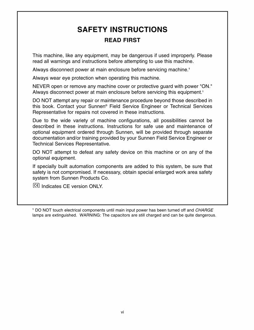
SAFETY INSTRUCTIONSREAD FIRST
This machine, like any equipment, may be dangerous if used improperly. Pleaseread all warnings and instructions before attempting to use this machine.
Always disconnect power at main enclosure before servicing machine.1
Always wear eye protection when operating this machine.
NEVER open or remove any machine cover or protective guard with power "ON."Always disconnect power at main enclosure before servicing this equipment.1
DO NOT attempt any repair or maintenance procedure beyond those described inthis book. Contact your Sunnen® Field Service Engineer or Technical ServicesRepresentative for repairs not covered in these instructions.
Due to the wide variety of machine configurations, all possibilities cannot bedescribed in these instructions. Instructions for safe use and maintenance ofoptional equipment ordered through Sunnen, will be provided through separatedocumentation and/or training provided by your Sunnen Field Service Engineer orTechnical Services Representative.
DO NOT attempt to defeat any safety device on this machine or on any of theoptional equipment.
If specially built automation components are added to this system, be sure thatsafety is not compromised. If necessary, obtain special enlarged work area safetysystem from Sunnen Products Co.
Indicates CE version ONLY.
1 DO NOT touch electrical components until main input power has been turned off and CHARGElamps are extinguished. WARNING: The capacitors are still charged and can be quite dangerous.
vi
Page 1
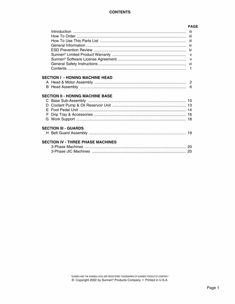
CONTENTS
Introduction .......................................................................................................... iiiHow To Order ...................................................................................................... iiiHow To Use This Parts List ................................................................................. iiiGeneral Information ............................................................................................. ivESD Prevention Review ...................................................................................... ivSunnen® Limited Product Warranty ..................................................................... vSunnen® Software License Agreement................................................................. vGeneral Safety Instructions .................................................................................. viContents ............................................................................................................... 1
SECTION I - HONING MACHINE HEADA Head & Motor Assembly ...................................................................................... 2B Head Assembly ................................................................................................... 6
SECTION II - HONING MACHINE BASEC Base Sub-Assembly ............................................................................................ 10D Coolant Pump & Oil Reservoir Unit ..................................................................... 13E Foot Pedal Unit .................................................................................................... 14F Drip Tray & Accessories ...................................................................................... 16G Work Support ....................................................................................................... 18
SECTION III - GUARDSH Belt Guard Assembly ........................................................................................... 19
SECTION IV - THREE PHASE MACHINES3-Phase Machines ............................................................................................... 203-Phase JIC Machines ........................................................................................ 20
PAGE
“SUNNEN AND THE SUNNEN LOGO ARE REGISTERED TRADEMARKS OF SUNNEN® PRODUCTS COMPANY.”
© Copyright 2002 by Sunnen® Products Company • Printed in U.S.A.
Page 2
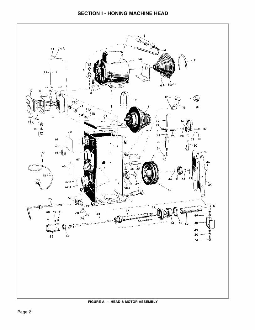
SECTION I - HONING MACHINE HEAD
FIGURE A – HEAD & MOTOR ASSEMBLY
Page 3
SECTION IHONING MACHINE HEAD
ITEMNO.
ORDER BYPART
NUMBER QTY.DESCRIPTION
1 PMO-312A 1 ....Motor (1/2 H.P., Nema 56 Frame, O.D.P., 115/230 Volt, 60 Hz, 1 ph.1725 RPM, 5/8 Dia. Shaft)
1 PMO-317A 1 ....Motor (1/2 H.P., Nerno 56 Frame, O.D.P., 220 Volt, 50 Hz, 1 ph.,1425 RPM, 5/8 Dia. Shaft)
1 PMO-364 1 ....Motor (1/2 H.P., Nema 56 Frame, O.D.P., 220/380 Volt, 50 Hz, 3 ph.,1425 RPM, 5/8 Dio. Shaft)
1 PMO-345A 1 ....Motor (1/2 H.P., Nema 56 Frame, O.D.P., 208/230/460 Volt, 60 Hz, 3 ph.,1725 RPM, 5/8 Dia. Shaft)
1 PMO-R345 1 ....Motor (1/2 H.P., Nema 56 Frame, T.E.N.V., 440 Volt, 50 Hz, 3 ph.1425 RPM, 5/8 Dia. Shaft)
2 KN-567 4 ....Screw (5/16-18 x 3/4 Hex Hd. Cap)3 KN-568 4 ....Washer (5/16 Plain)4 MBB-1665A* 1 ....Wire Lead & Connector Set5 PEC-114A* 2 ....Cable Connector (Pkg. of 1)
5A MBB-2606A 1 ....Guard (For 208/230/460/440 Volt, 3 ph. Only)6 MBB-2622A 1 ....Drive Pulley (60 Hz Machines) with
6A LN-1345 1 ......Set Screw (10-32 x 3/8 Soc. Cup Pt.)6B MBB-2632A 1 ....Drive Pulley (50 Hz Machines) with6A LN-1345 1 ......Set Screw (10-32 x 3/8 Soc. Cup Pt.)7 MBB-2620A 1 ...."V" Belt 8 MBB-2665A 1 ....Countershaft Pulley with Bearing (60 Hz Machines)
8A MBB-2675A 1 ....Countershaft Pulley with Bearing (50 Hz Machines)9 MBB-910 1 ....Flat Belt (37-1/4 Inside Circumference)10 MBB-1671A* 1 ....Switch Box with
10A PHS-940 3 ......Screw (6-32 x 3/8 Self-Tapping Pan Hd.)11 MBB-1672A* 1 ....Switch Bracket with
11A MSA-219 2 ......Screw (1/4-20 x 3/8 Hex Hd. Cap)12 MBB-1676A* 1 ....Switch & Cover with
12A PHS-671 2 ......Screw (6-32 x 1" Pan Hd.)14 PEC-112A* 1 ....Cable Connector (For 115V and 230V)15 PEC-62A* 1 ....Cord Set (For 115 Volt, 1 phase)15 PEC-61A 1 ....Cord Set (For 230 Volt, 1 phase)16 LBB-1129A 1 ....Idler Arm with17 MBB-312 2 ......Set Screw (3/8-16 x 1/2 Soc. Cup Pt.)18 LBB-825A 1 ....Idler Pulley Assembly22 MBB-968A 1 ....Brake Adjusting Screw with23 LBN-431 1 ......Nut (1/4-20 Hex)24 MBB-978A 1 ....Brake Lever with25 MBB-977 1 ......Shoulder Screw (5/16 x 5/8 with 1/4-20 x 7/16 th’d)N/S PHN-121 1 ......Locknut (1/4-20 Hex)26 MBB-973A 1 ....Brake Cam with27 MBB-971 1 ......Screw (5/16-18 x 1" Soc. Hd. Cap)28 MBB-972 1 ......Washer (5/16 Serrated Lock)30 MBB-969A 1 ....Brake Strap with31 MSN-277 1 ......Screw (10-32 x 3/8 Rd. Hd.)32 MBH-396 1 ......Washer (Bent)33 MBB-985A 1 ....Brake Rod Assembly with
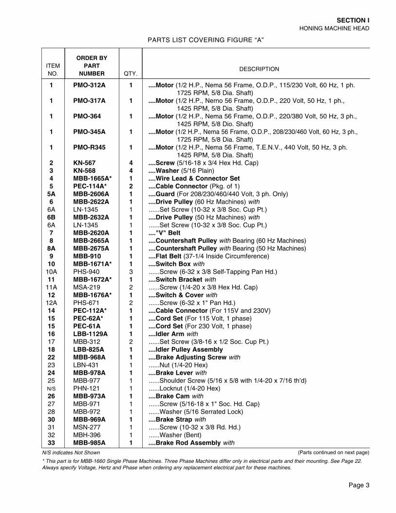
PARTS LIST COVERING FIGURE “A”
(Parts continued on next page)N/S indicates Not Shown
* This part is for MBB-1660 Single Phase Machines. Three Phase Machines differ only in electrical parts and their mounting. See Page 22.Always specify Voltage, Hertz and Phase when ordering any replacement electrical part for these machines.
Page 4
SECTION IHONING MACHINE HEAD
ITEMNO.
ORDER BYPART
NUMBER QTY.DESCRIPTION
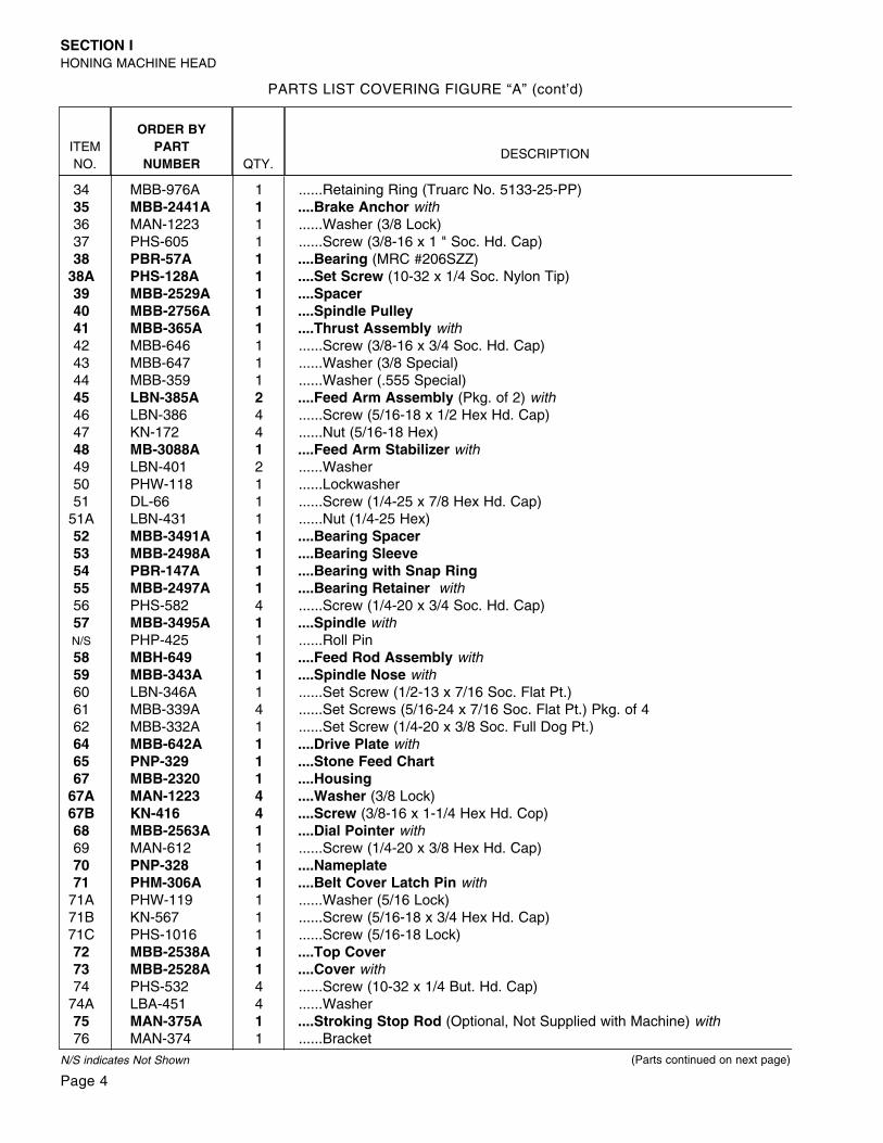
34 MBB-976A 1 ......Retaining Ring (Truarc No. 5133-25-PP)35 MBB-2441A 1 ....Brake Anchor with36 MAN-1223 1 ......Washer (3/8 Lock)37 PHS-605 1 ......Screw (3/8-16 x 1 " Soc. Hd. Cap)38 PBR-57A 1 ....Bearing (MRC #206SZZ)
38A PHS-128A 1 ....Set Screw (10-32 x 1/4 Soc. Nylon Tip)39 MBB-2529A 1 ....Spacer40 MBB-2756A 1 ....Spindle Pulley41 MBB-365A 1 ....Thrust Assembly with42 MBB-646 1 ......Screw (3/8-16 x 3/4 Soc. Hd. Cap)43 MBB-647 1 ......Washer (3/8 Special)44 MBB-359 1 ......Washer (.555 Special)45 LBN-385A 2 ....Feed Arm Assembly (Pkg. of 2) with46 LBN-386 4 ......Screw (5/16-18 x 1/2 Hex Hd. Cap)47 KN-172 4 ......Nut (5/16-18 Hex)48 MB-3088A 1 ....Feed Arm Stabilizer with49 LBN-401 2 ......Washer50 PHW-118 1 ......Lockwasher51 DL-66 1 ......Screw (1/4-25 x 7/8 Hex Hd. Cap)
51A LBN-431 1 ......Nut (1/4-25 Hex)52 MBB-3491A 1 ....Bearing Spacer 53 MBB-2498A 1 ....Bearing Sleeve54 PBR-147A 1 ....Bearing with Snap Ring55 MBB-2497A 1 ....Bearing Retainer with56 PHS-582 4 ......Screw (1/4-20 x 3/4 Soc. Hd. Cap)57 MBB-3495A 1 ....Spindle withN/S PHP-425 1 ......Roll Pin58 MBH-649 1 ....Feed Rod Assembly with59 MBB-343A 1 ....Spindle Nose with60 LBN-346A 1 ......Set Screw (1/2-13 x 7/16 Soc. Flat Pt.)61 MBB-339A 4 ......Set Screws (5/16-24 x 7/16 Soc. Flat Pt.) Pkg. of 462 MBB-332A 1 ......Set Screw (1/4-20 x 3/8 Soc. Full Dog Pt.)64 MBB-642A 1 ....Drive Plate with65 PNP-329 1 ....Stone Feed Chart 67 MBB-2320 1 ....Housing
67A MAN-1223 4 ....Washer (3/8 Lock)67B KN-416 4 ....Screw (3/8-16 x 1-1/4 Hex Hd. Cop)68 MBB-2563A 1 ....Dial Pointer with69 MAN-612 1 ......Screw (1/4-20 x 3/8 Hex Hd. Cap)70 PNP-328 1 ....Nameplate 71 PHM-306A 1 ....Belt Cover Latch Pin with
71A PHW-119 1 ......Washer (5/16 Lock)71B KN-567 1 ......Screw (5/16-18 x 3/4 Hex Hd. Cap)71C PHS-1016 1 ......Screw (5/16-18 Lock)72 MBB-2538A 1 ....Top Cover73 MBB-2528A 1 ....Cover with74 PHS-532 4 ......Screw (10-32 x 1/4 But. Hd. Cap)
74A LBA-451 4 ......Washer75 MAN-375A 1 ....Stroking Stop Rod (Optional, Not Supplied with Machine) with76 MAN-374 1 ......Bracket
PARTS LIST COVERING FIGURE “A” (cont’d)
(Parts continued on next page)N/S indicates Not Shown
Page 5
SECTION IHONING MACHINE HEAD
ITEMNO.
ORDER BYPART
NUMBER QTY.DESCRIPTION
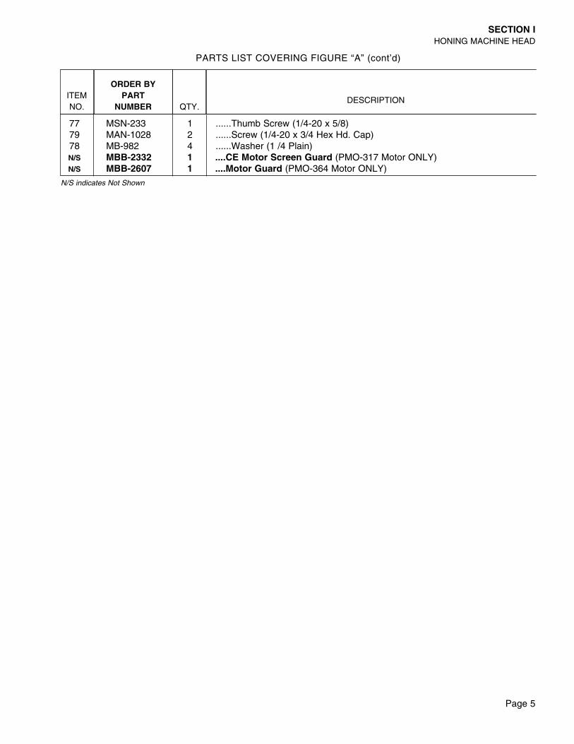
77 MSN-233 1 ......Thumb Screw (1/4-20 x 5/8)79 MAN-1028 2 ......Screw (1/4-20 x 3/4 Hex Hd. Cap)78 MB-982 4 ......Washer (1 /4 Plain)N/S MBB-2332 1 ....CE Motor Screen Guard (PMO-317 Motor ONLY)N/S MBB-2607 1 ....Motor Guard (PMO-364 Motor ONLY)
PARTS LIST COVERING FIGURE “A” (cont’d)
N/S indicates Not Shown
Page 6
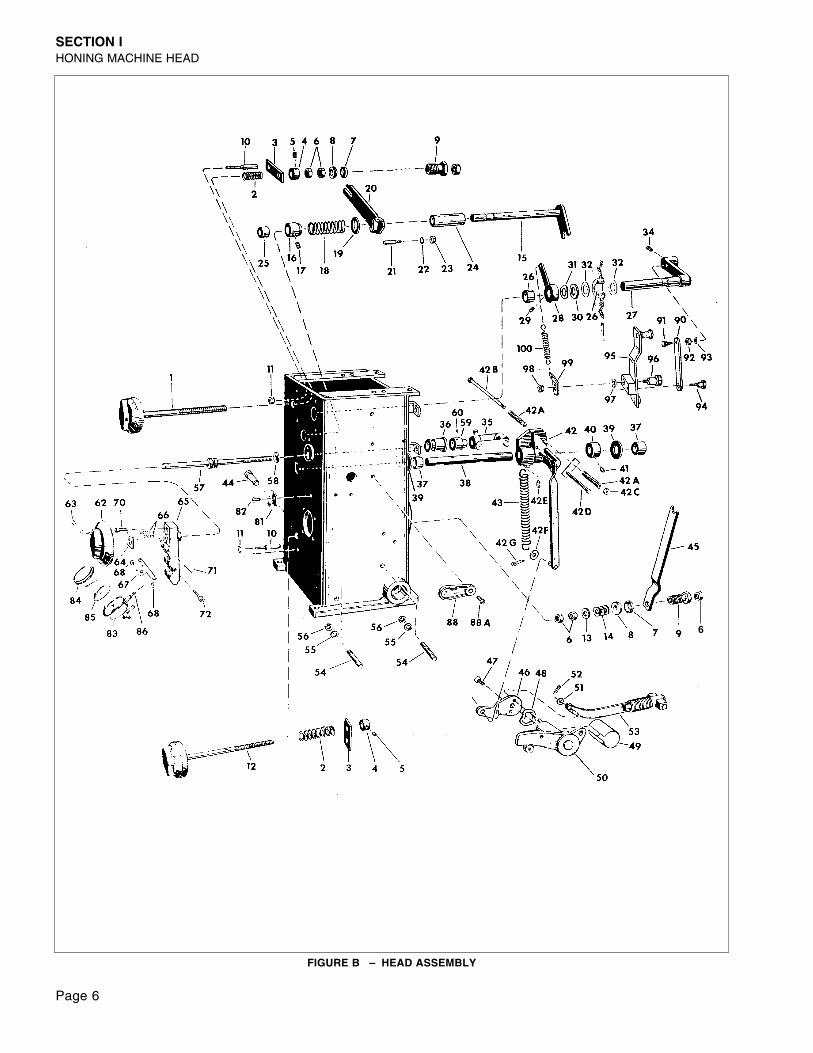
SECTION IHONING MACHINE HEAD
FIGURE B – HEAD ASSEMBLY
6
Page 7
SECTION IHONING MACHINE HEAD
ITEMNO.
ORDER BYPART
NUMBER QTY.DESCRIPTION
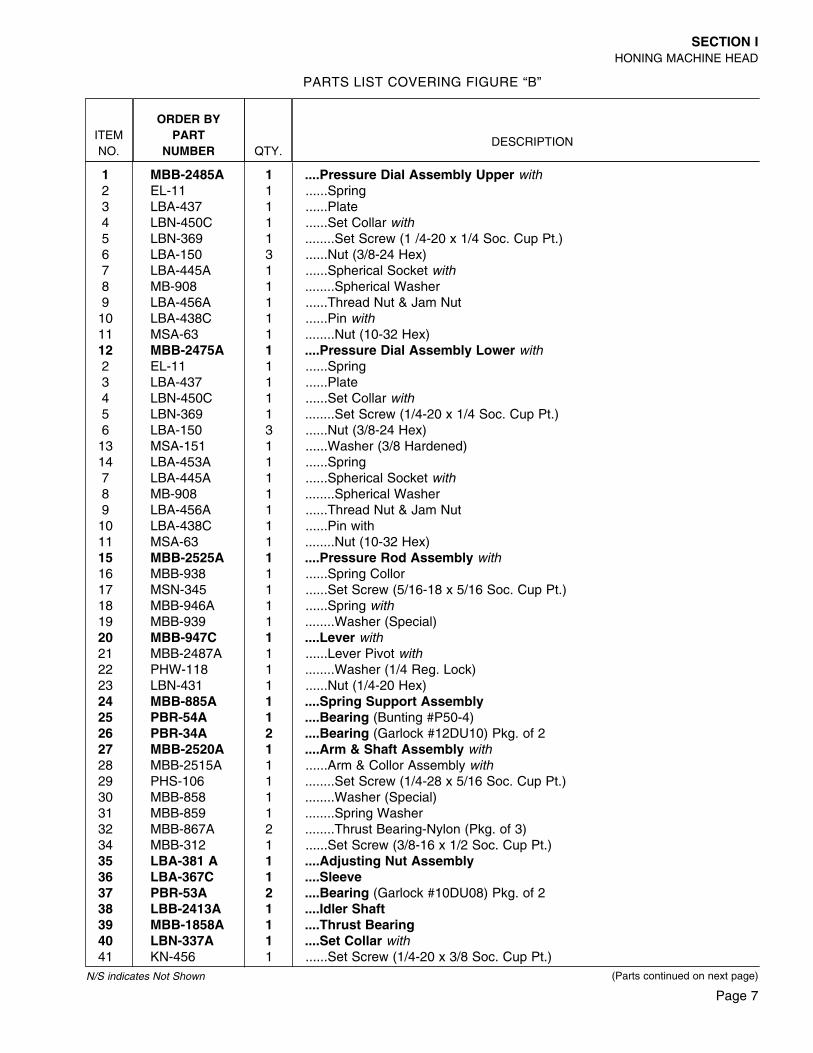
1 MBB-2485A 1 ....Pressure Dial Assembly Upper with2 EL-11 1 ......Spring3 LBA-437 1 ......Plate4 LBN-450C 1 ......Set Collar with5 LBN-369 1 ........Set Screw (1 /4-20 x 1/4 Soc. Cup Pt.)6 LBA-150 3 ......Nut (3/8-24 Hex)7 LBA-445A 1 ......Spherical Socket with8 MB-908 1 ........Spherical Washer9 LBA-456A 1 ......Thread Nut & Jam Nut10 LBA-438C 1 ......Pin with11 MSA-63 1 ........Nut (10-32 Hex)12 MBB-2475A 1 ....Pressure Dial Assembly Lower with2 EL-11 1 ......Spring3 LBA-437 1 ......Plate4 LBN-450C 1 ......Set Collar with5 LBN-369 1 ........Set Screw (1/4-20 x 1/4 Soc. Cup Pt.)6 LBA-150 3 ......Nut (3/8-24 Hex)13 MSA-151 1 ......Washer (3/8 Hardened)14 LBA-453A 1 ......Spring7 LBA-445A 1 ......Spherical Socket with8 MB-908 1 ........Spherical Washer9 LBA-456A 1 ......Thread Nut & Jam Nut10 LBA-438C 1 ......Pin with11 MSA-63 1 ........Nut (10-32 Hex)15 MBB-2525A 1 ....Pressure Rod Assembly with16 MBB-938 1 ......Spring Collor17 MSN-345 1 ......Set Screw (5/16-18 x 5/16 Soc. Cup Pt.)18 MBB-946A 1 ......Spring with19 MBB-939 1 ........Washer (Special)20 MBB-947C 1 ....Lever with21 MBB-2487A 1 ......Lever Pivot with22 PHW-118 1 ........Washer (1/4 Reg. Lock)23 LBN-431 1 ......Nut (1/4-20 Hex)24 MBB-885A 1 ....Spring Support Assembly25 PBR-54A 1 ....Bearing (Bunting #P50-4)26 PBR-34A 2 ....Bearing (Garlock #12DU10) Pkg. of 227 MBB-2520A 1 ....Arm & Shaft Assembly with28 MBB-2515A 1 ......Arm & Collor Assembly with29 PHS-106 1 ........Set Screw (1/4-28 x 5/16 Soc. Cup Pt.)30 MBB-858 1 ........Washer (Special)31 MBB-859 1 ........Spring Washer32 MBB-867A 2 ........Thrust Bearing-Nylon (Pkg. of 3)34 MBB-312 1 ......Set Screw (3/8-16 x 1/2 Soc. Cup Pt.)35 LBA-381 A 1 ....Adjusting Nut Assembly36 LBA-367C 1 ....Sleeve37 PBR-53A 2 ....Bearing (Garlock #10DU08) Pkg. of 238 LBB-2413A 1 ....Idler Shaft39 MBB-1858A 1 ....Thrust Bearing40 LBN-337A 1 ....Set Collar with41 KN-456 1 ......Set Screw (1/4-20 x 3/8 Soc. Cup Pt.)
PARTS LIST COVERING FIGURE “B”
(Parts continued on next page)N/S indicates Not Shown
Page 8
SECTION IHONING MACHINE HEAD
ITEMNO.
ORDER BYPART
NUMBER QTY.DESCRIPTION
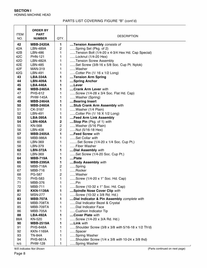
42 MBB-2420A 1 ....Tension Assembly consists of42A LBN-489A 2 ......Spring Set (Pkg. of 2)42B LBN-486 1 ......Tension Bolt (1/4-20 x 4-3/4 Hex Hd. Cap Special)42C PHN-121 1 ......Locknut (1/4-20 Hex)42D LBN-482A 1 ......Tension Screw Assembly42E LBN-485 1 ......Set Screw (3/8-16 x 5/8 Soc. Cup Pt. Nylok)42F MAN-319 1 ......Washer42G LBN-491 1 ......Cotter Pin (1/ 16 x 1/2 Long)43 LBA-334A 1 ....Tension Arm Spring44 LBN-409A 1 ....Spring Anchor45 LBA-446A 1 ....Lever46 MBB-2465A 1 ....Crank Arm Lever with47 PHS-612 1 ......Screw (1/4-28 x 3/4 Soc. Flat Hd. Cap)48 PHW-145A 1 ......Washer (Spring)49 MBB-2464A 1 ....Bearing Insert50 MBB-2460A 1 ....Stub Crank Arm Assembly with51 CK-3187 1 ......Washer (1/4 Plain)52 LBN-491 1 ......Cotter Pin (1/ 16 X 1/2 Long)53 LBA-395A 1 ....Feed Arm Link Assembly54 LBN-406A 2 ....Stop Pin (Pkg. of 1) with55 KN-568 2 ......Washer (5/16 Plain)56 LBN-408 2 ......Nut (5/16-18 Hex)57 MBB-2405A 1 ....Feed Screw with59 MBB-986A 1 ......Set Collar with60 LBN-369 1 ........Set Screw (1/4-20 x 1/4 Soc. Cup Pt.)58 LBN-379 1 ......Fiber Washer62 LBN-372A 1 ....Dial Assembly with63 LBN-369 1 ......Set Screw (1/4-20 Soc. Cup Pt.)64 MBB-719A 1 ....Plate65 MBB-2395A 1 ....Body Assembly with66 MBB-718A 2 ......Spring67 MBB-716 1 ......Rocker68 PG-587 2 ......Washer70 PHS-583 1 ......Screw (1/4-20 x 1” Soc. Hd. Cap)71 MBB-376 1 ......Pin72 MBB-711 1 ......Screw (10-32 x 1" Soc. Hd. Cap)81 KKN-1139A 1 ....Spindle Nose Cover Clip with82 MSN-277 1 ......Screw (10-32 x 3/8 Rd. Hd.)83 MBB-707A 1 ....Dial Indicator & Pin Assembly complete with84 MBB-708TA 1 ......Dial Indicator Bezel & Crystal85 MBB-709TA 1 ......Dial Indicator Face86 MBB-705A 1 ......Cushion Indicator Tip88 LBA-492A 1 ....Cover Plate with
88A KN-520 1 ......Screw (1/4-20 x 3/A Rd. Hd.)90 MBB-2519A 1 ....Link with91 PHS-648A 1 ......Shoulder Screw (3/8 x 3/8 with 5/16-18 x 1/2 Th'd)92 KKN-1169A 1 ......Spacer93 TN-84A 1 ......Spring Washer94 PHS-661A 1 ......Shoulder Screw (1/4 x 3/8 with 10-24 x 3/8 thd)N/S PHW-128 1 ......Spring Washer
PARTS LIST COVERING FIGURE “B” (cont’d)
(Parts continued on next page)N/S indicates Not Shown
Page 9
SECTION IHONING MACHINE HEAD
ITEMNO.
ORDER BYPART
NUMBER QTY.DESCRIPTION
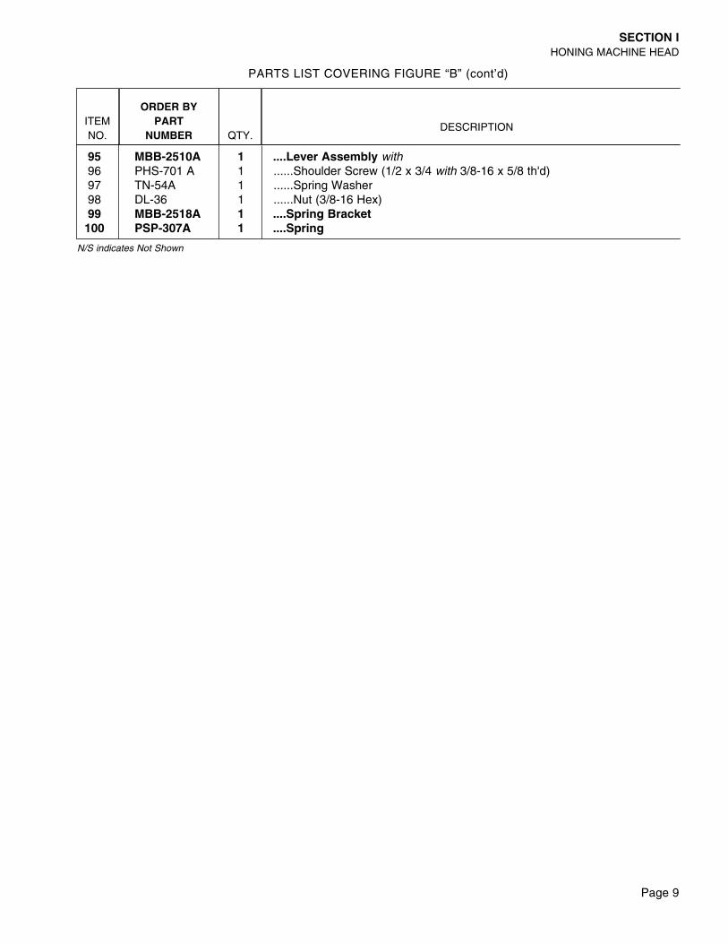
95 MBB-2510A 1 ....Lever Assembly with96 PHS-701 A 1 ......Shoulder Screw (1/2 x 3/4 with 3/8-16 x 5/8 th'd)97 TN-54A 1 ......Spring Washer98 DL-36 1 ......Nut (3/8-16 Hex)99 MBB-2518A 1 ....Spring Bracket100 PSP-307A 1 ....Spring
PARTS LIST COVERING FIGURE “B” (cont’d)
N/S indicates Not Shown
Page 10
SECTION II - HONING MACHINE BASE
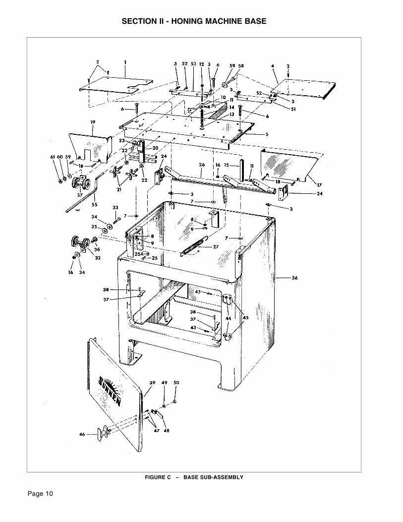
FIGURE C – BASE SUB-ASSEMBLY
Page 11
SECTION IIHONING MACHINE BASE
ITEMNO.
ORDER BYPART
NUMBER QTY.DESCRIPTION
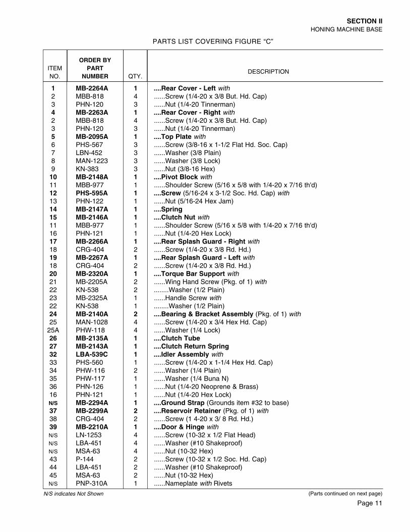
1 MB-2264A 1 ....Rear Cover - Left with2 MBB-818 4 ......Screw (1/4-20 x 3/8 But. Hd. Cap)3 PHN-120 3 ......Nut (1/4-20 Tinnerman)4 MB-2263A 1 ....Rear Cover - Right with2 MBB-818 4 ......Screw (1/4-20 x 3/8 But. Hd. Cap)3 PHN-120 3 ......Nut (1/4-20 Tinnerman)5 MB-2095A 1 ....Top Plate with6 PHS-567 3 ......Screw (3/8-16 x 1-1/2 Flat Hd. Soc. Cap)7 LBN-452 3 ......Washer (3/8 Plain)8 MAN-1223 3 ......Washer (3/8 Lock)9 KN-383 3 ......Nut (3/8-16 Hex)10 MB-2148A 1 ....Pivot Block with11 MBB-977 1 ......Shoulder Screw (5/16 x 5/8 with 1/4-20 x 7/16 th'd)12 PHS-595A 1 ....Screw (5/16-24 x 3-1/2 Soc. Hd. Cap) with13 PHN-122 1 ......Nut (5/16-24 Hex Jam)14 MB-2147A 1 ....Spring15 MB-2146A 1 ....Clutch Nut with11 MBB-977 1 ......Shoulder Screw (5/16 x 5/8 with 1/4-20 x 7/16 th'd)16 PHN-121 1 ......Nut (1/4-20 Hex Lock)17 MB-2266A 1 ....Rear Splash Guard - Right with18 CRG-404 2 ......Screw (1/4-20 x 3/8 Rd. Hd.)19 MB-2267A 1 ....Rear Splash Guard - Left with18 CRG-404 2 ......Screw (1/4-20 x 3/8 Rd. Hd.)20 MB-2320A 1 ....Torque Bar Support with21 MB-2205A 2 ......Wing Hand Screw (Pkg. of 1) with22 KN-538 2 ........Washer (1/2 Plain)23 MB-2325A 1 ......Handle Screw with22 KN-538 1 ........Washer (1/2 Plain)24 MB-2140A 2 ....Bearing & Bracket Assembly (Pkg. of 1) with25 MAN-1028 4 ......Screw (1/4-20 x 3/4 Hex Hd. Cap)
25A PHW-118 4 ......Washer (1/4 Lock)26 MB-2135A 1 ....Clutch Tube27 MB-2143A 1 ....Clutch Return Spring32 LBA-539C 1 ....Idler Assembly with33 PHS-560 1 ......Screw (1/4-20 x 1-1/4 Hex Hd. Cap)34 PHW-116 2 ......Washer (1/4 Plain)35 PHW-117 1 ......Washer (1/4 Buna N)36 PHN-126 1 ......Nut (1/4-20 Neoprene & Brass)16 PHN-121 1 ......Nut (1/4-20 Hex Lock)N/S MB-2294A 1 ....Ground Strap (Grounds item #32 to base)37 MB-2299A 2 ....Reservoir Retainer (Pkg. of 1) with38 CRG-404 2 ......Screw (1 4-20 x 3/ 8 Rd. Hd.)39 MB-2210A 1 ....Door & Hinge withN/S LN-1253 4 ......Screw (10-32 x 1/2 Flat Head)N/S LBA-451 4 ......Washer (#10 Shakeproof)N/S MSA-63 4 ......Nut (10-32 Hex)43 P-144 2 ......Screw (10-32 x 1/2 Soc. Hd. Cap)44 LBA-451 2 ......Washer (#10 Shakeproof)45 MSA-63 2 ......Nut (10-32 Hex)N/S PNP-310A 1 ......Nameplate with Rivets
PARTS LIST COVERING FIGURE “C”
(Parts continued on next page)N/S indicates Not Shown
Page 12
SECTION IIHONING MACHINE BASE
ITEMNO.
ORDER BYPART
NUMBER QTY.DESCRIPTION
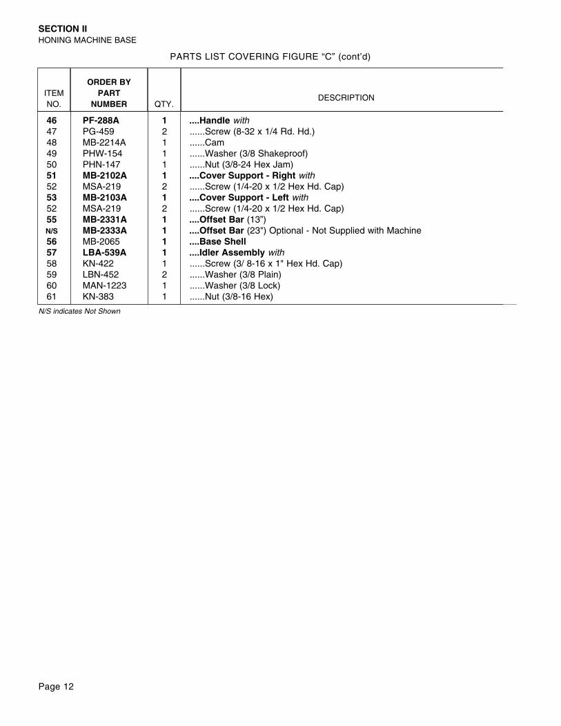
46 PF-288A 1 ....Handle with47 PG-459 2 ......Screw (8-32 x 1/4 Rd. Hd.)48 MB-2214A 1 ......Cam49 PHW-154 1 ......Washer (3/8 Shakeproof)50 PHN-147 1 ......Nut (3/8-24 Hex Jam)51 MB-2102A 1 ....Cover Support - Right with52 MSA-219 2 ......Screw (1/4-20 x 1/2 Hex Hd. Cap)53 MB-2103A 1 ....Cover Support - Left with52 MSA-219 2 ......Screw (1/4-20 x 1/2 Hex Hd. Cap)55 MB-2331A 1 ....Offset Bar (13”)N/S MB-2333A 1 ....Offset Bar (23") Optional - Not Supplied with Machine56 MB-2065 1 ....Base Shell57 LBA-539A 1 ....Idler Assembly with58 KN-422 1 ......Screw (3/ 8-16 x 1" Hex Hd. Cap)59 LBN-452 2 ......Washer (3/8 Plain)60 MAN-1223 1 ......Washer (3/8 Lock)61 KN-383 1 ......Nut (3/8-16 Hex)
PARTS LIST COVERING FIGURE “C” (cont’d)
N/S indicates Not Shown
SECTION IIHONING MACHINE BASE
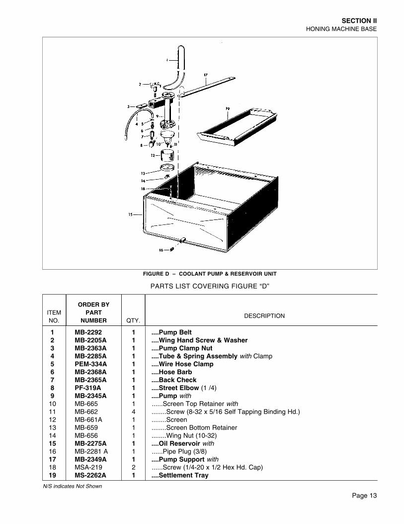
FIGURE D – COOLANT PUMP & RESERVOIR UNIT
ITEMNO.
ORDER BYPART
NUMBER QTY.DESCRIPTION
1 MB-2292 1 ....Pump Belt2 MB-2205A 1 ....Wing Hand Screw & Washer3 MB-2363A 1 ....Pump Clamp Nut4 MB-2285A 1 ....Tube & Spring Assembly with Clamp5 PEM-334A 1 ....Wire Hose Clamp6 MB-2368A 1 ....Hose Barb7 MB-2365A 1 ....Back Check8 PF-319A 1 ....Street Elbow (1 /4)9 MB-2345A 1 ....Pump with10 MB-665 1 ......Screen Top Retainer with11 MB-662 4 ........Screw (8-32 x 5/16 Self Tapping Binding Hd.)12 MB-661A 1 ........Screen13 MB-659 1 ........Screen Bottom Retainer14 MB-656 1 ........Wing Nut (10-32)15 MB-2275A 1 ....Oil Reservoir with16 MB-2281 A 1 ......Pipe Plug (3/8)17 MB-2349A 1 ....Pump Support with18 MSA-219 2 ......Screw (1/4-20 x 1/2 Hex Hd. Cap)19 MS-2262A 1 ....Settlement Tray
PARTS LIST COVERING FIGURE “D”
N/S indicates Not Shown
Page 13
Page 14
SECTION IIHONING MACHINE BASE
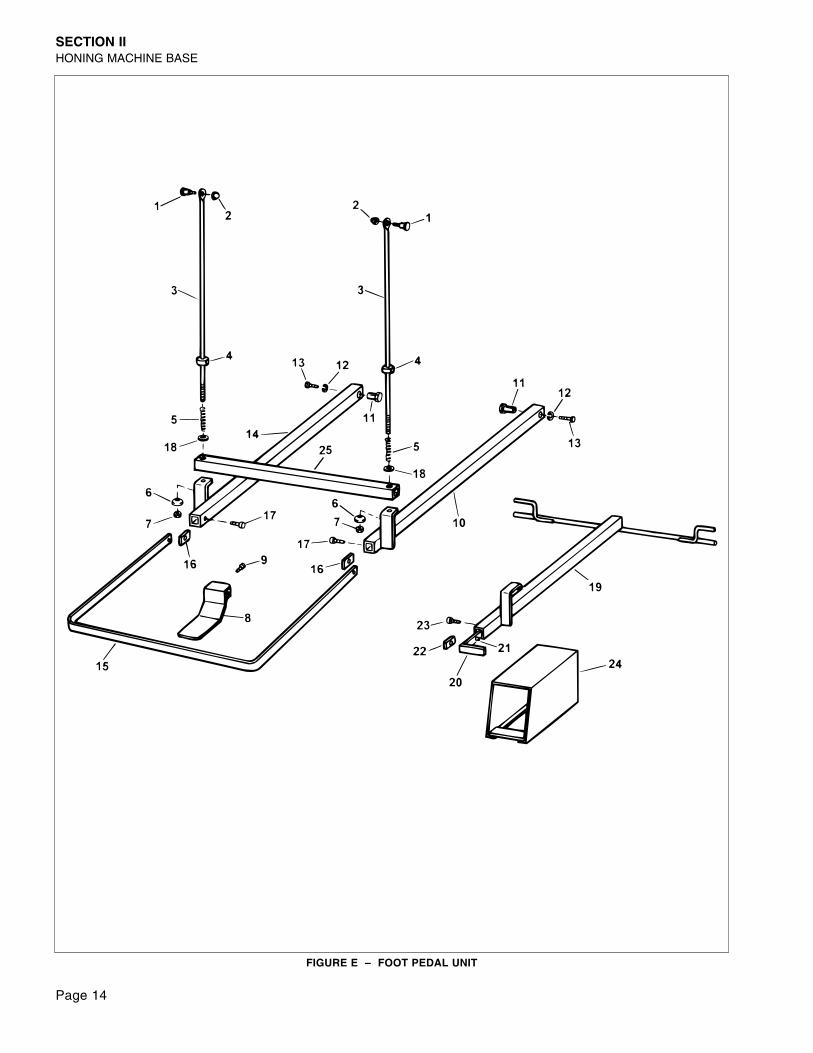
FIGURE E – FOOT PEDAL UNIT
Page 15
SECTION IIHONING MACHINE BASE
N/S indicates Not Shown
ITEMNO.
ORDER BYPART
NUMBER QTY.DESCRIPTION
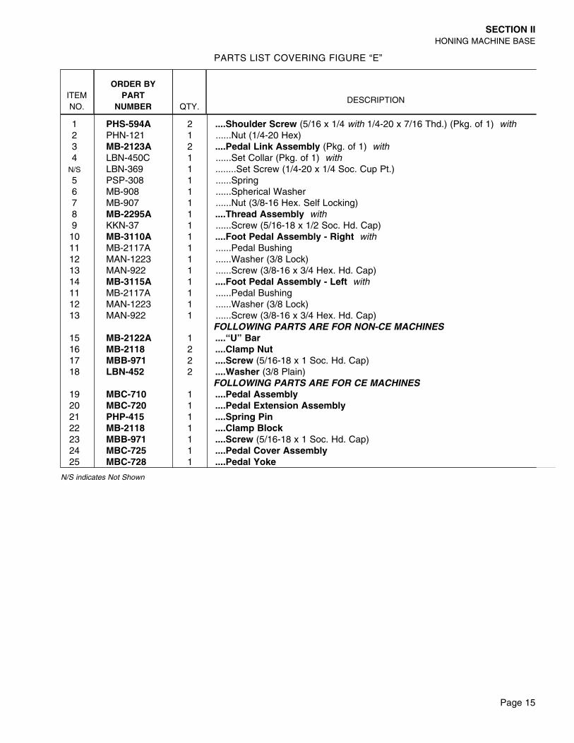
PARTS LIST COVERING FIGURE “E”
1 PHS-594A 2 ....Shoulder Screw (5/16 x 1/4 with 1/4-20 x 7/16 Thd.) (Pkg. of 1) with2 PHN-121 1 ......Nut (1/4-20 Hex)3 MB-2123A 2 ....Pedal Link Assembly (Pkg. of 1) with4 LBN-450C 1 ......Set Collar (Pkg. of 1) with
N/S LBN-369 1 ........Set Screw (1/4-20 x 1/4 Soc. Cup Pt.)5 PSP-308 1 ......Spring6 MB-908 1 ......Spherical Washer7 MB-907 1 ......Nut (3/8-16 Hex. Self Locking)8 MB-2295A 1 ....Thread Assembly with9 KKN-37 1 ......Screw (5/16-18 x 1/2 Soc. Hd. Cap)10 MB-3110A 1 ....Foot Pedal Assembly - Right with11 MB-2117A 1 ......Pedal Bushing12 MAN-1223 1 ......Washer (3/8 Lock)13 MAN-922 1 ......Screw (3/8-16 x 3/4 Hex. Hd. Cap)14 MB-3115A 1 ....Foot Pedal Assembly - Left with11 MB-2117A 1 ......Pedal Bushing12 MAN-1223 1 ......Washer (3/8 Lock)13 MAN-922 1 ......Screw (3/8-16 x 3/4 Hex. Hd. Cap)
FOLLOWING PARTS ARE FOR NON-CE MACHINES15 MB-2122A 1 ....“U” Bar16 MB-2118 2 ....Clamp Nut17 MBB-971 2 ....Screw (5/16-18 x 1 Soc. Hd. Cap)18 LBN-452 2 ....Washer (3/8 Plain)
FOLLOWING PARTS ARE FOR CE MACHINES19 MBC-710 1 ....Pedal Assembly20 MBC-720 1 ....Pedal Extension Assembly21 PHP-415 1 ....Spring Pin22 MB-2118 1 ....Clamp Block23 MBB-971 1 ....Screw (5/16-18 x 1 Soc. Hd. Cap)24 MBC-725 1 ....Pedal Cover Assembly25 MBC-728 1 ....Pedal Yoke
Page 16
SECTION IIHONING MACHINE BASE
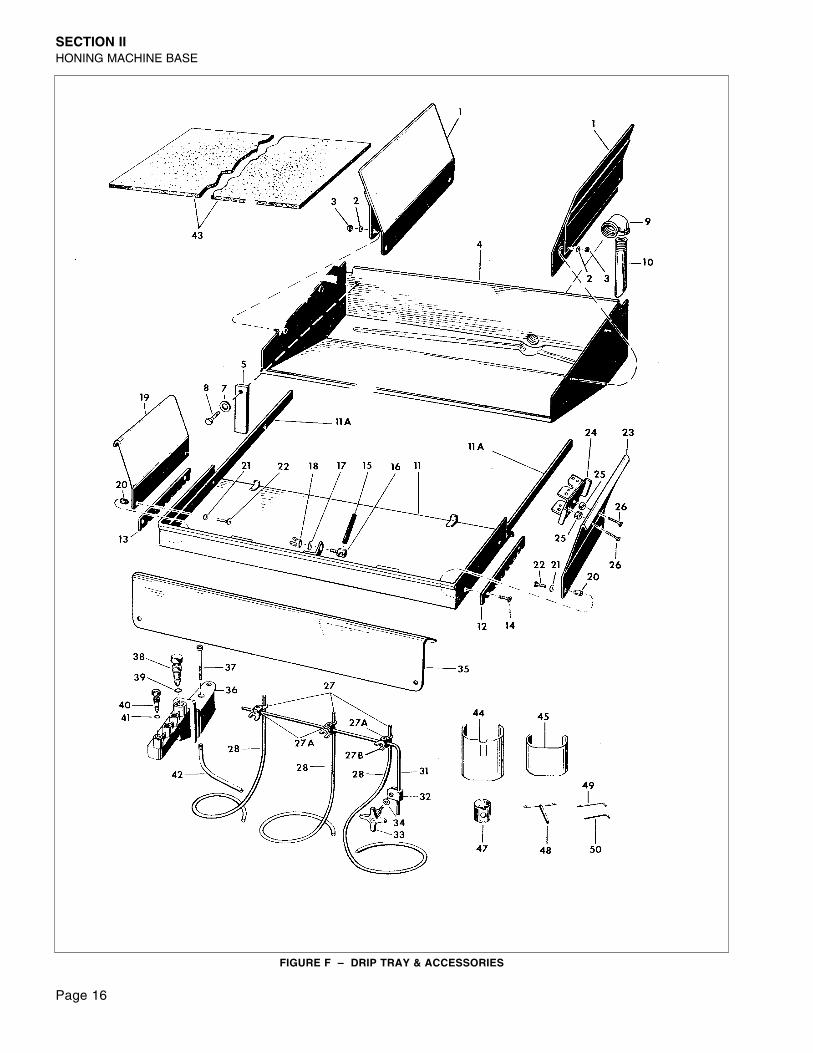
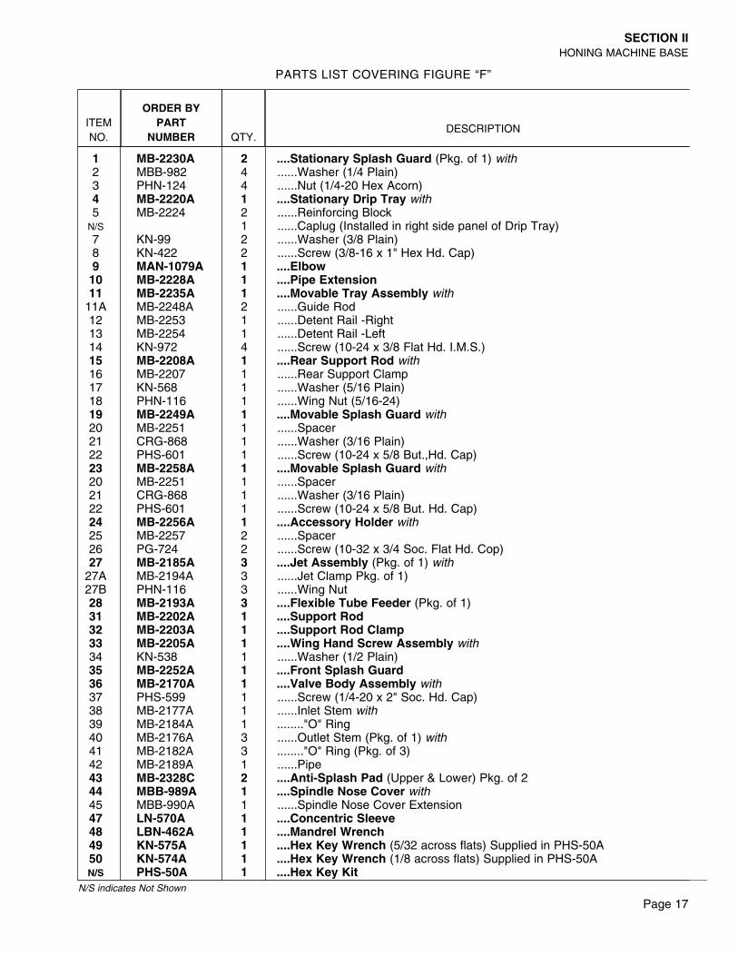
FIGURE F – DRIP TRAY & ACCESSORIES
Page 17
SECTION IIHONING MACHINE BASE
ITEMNO.
ORDER BYPART
NUMBER QTY.DESCRIPTION
1 MB-2230A 2 ....Stationary Splash Guard (Pkg. of 1) with2 MBB-982 4 ......Washer (1/4 Plain)3 PHN-124 4 ......Nut (1/4-20 Hex Acorn)4 MB-2220A 1 ....Stationary Drip Tray with5 MB-2224 2 ......Reinforcing Block
N/S 1 ......Caplug (Installed in right side panel of Drip Tray)7 KN-99 2 ......Washer (3/8 Plain)8 KN-422 2 ......Screw (3/8-16 x 1" Hex Hd. Cap)9 MAN-1079A 1 ....Elbow10 MB-2228A 1 ....Pipe Extension11 MB-2235A 1 ....Movable Tray Assembly with
11A MB-2248A 2 ......Guide Rod12 MB-2253 1 ......Detent Rail -Right13 MB-2254 1 ......Detent Rail -Left14 KN-972 4 ......Screw (10-24 x 3/8 Flat Hd. I.M.S.)15 MB-2208A 1 ....Rear Support Rod with16 MB-2207 1 ......Rear Support Clamp17 KN-568 1 ......Washer (5/16 Plain)18 PHN-116 1 ......Wing Nut (5/16-24)19 MB-2249A 1 ....Movable Splash Guard with20 MB-2251 1 ......Spacer21 CRG-868 1 ......Washer (3/16 Plain)22 PHS-601 1 ......Screw (10-24 x 5/8 But.,Hd. Cap)23 MB-2258A 1 ....Movable Splash Guard with20 MB-2251 1 ......Spacer21 CRG-868 1 ......Washer (3/16 Plain)22 PHS-601 1 ......Screw (10-24 x 5/8 But. Hd. Cap)24 MB-2256A 1 ....Accessory Holder with25 MB-2257 2 ......Spacer26 PG-724 2 ......Screw (10-32 x 3/4 Soc. Flat Hd. Cop)27 MB-2185A 3 ....Jet Assembly (Pkg. of 1) with
27A MB-2194A 3 ......Jet Clamp Pkg. of 1)27B PHN-116 3 ......Wing Nut28 MB-2193A 3 ....Flexible Tube Feeder (Pkg. of 1)31 MB-2202A 1 ....Support Rod32 MB-2203A 1 ....Support Rod Clamp33 MB-2205A 1 ....Wing Hand Screw Assembly with34 KN-538 1 ......Washer (1/2 Plain)35 MB-2252A 1 ....Front Splash Guard36 MB-2170A 1 ....Valve Body Assembly with37 PHS-599 1 ......Screw (1/4-20 x 2" Soc. Hd. Cap)38 MB-2177A 1 ......Inlet Stem with39 MB-2184A 1 ........"O" Ring40 MB-2176A 3 ......Outlet Stem (Pkg. of 1) with41 MB-2182A 3 ........"O" Ring (Pkg. of 3)42 MB-2189A 1 ......Pipe43 MB-2328C 2 ....Anti-Splash Pad (Upper & Lower) Pkg. of 244 MBB-989A 1 ....Spindle Nose Cover with45 MBB-990A 1 ......Spindle Nose Cover Extension47 LN-570A 1 ....Concentric Sleeve48 LBN-462A 1 ....Mandrel Wrench49 KN-575A 1 ....Hex Key Wrench (5/32 across flats) Supplied in PHS-50A50 KN-574A 1 ....Hex Key Wrench (1/8 across flats) Supplied in PHS-50AN/S PHS-50A 1 ....Hex Key Kit
PARTS LIST COVERING FIGURE “F”
N/S indicates Not Shown
Page 18
SECTION IIHONING MACHINE BASE
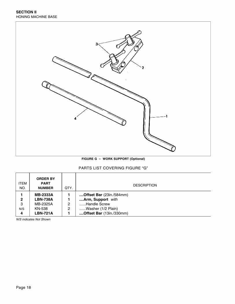
FIGURE G – WORK SUPPORT (Optional)
ITEMNO.
ORDER BYPART
NUMBER QTY.DESCRIPTION
1 MB-2333A 1 ....Offset Bar (23in./584mm)2 LBN-738A 1 ....Arm, Support with3 MB-2325A 2 ......Handle Screw
N/S KN-538 2 ......Washer (1/2 Plain)4 LBN-721A 1 ....Offset Bar (13in./330mm)
PARTS LIST COVERING FIGURE “G”
N/S indicates Not Shown
Page 19
SECTION III - GUARDS
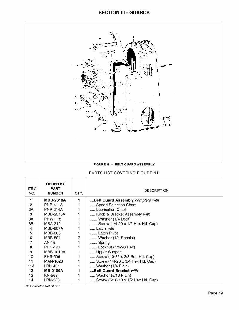
FIGURE H – BELT GUARD ASSEMBLY
ITEMNO.
ORDER BYPART
NUMBER QTY.DESCRIPTION
1 MBB-2610A 1 ....Belt Guard Assembly complete with2 PNP-411A 1 ......Speed Selection Chart
2A PNP-214A 1 ......Lubrication Chart3 MBB-2545A 1 ......Knob & Bracket Assembly with
3A PHW-118 1 ........Washer (1/4 Lock)3B MSA-219 1 ........Screw (1/4-20 x 1/2 Hex Hd. Cap)4 MBB-807A 1 ......Latch with5 MBB-806 1 ........Latch Pivot6 MBB-804 2 ........Washer (1/4 Special)7 AN-15 1 ........Spring8 PHN-121 1 ........Locknut (1/4-20 Hex)9 MBB-1019A 1 ......Upper Support10 PHS-506 1 ......Screw (10-32 x 3/8 But. Hd. Cap)11 MAN-1028 1 ......Screw (1/4-20 x 3/4 Hex Hd. Cap)
11A LBN-401 1 ......Washer (1/4 Plain)12 MB-2109A 1 ....Belt Guard Bracket with13 KN-568 1 ......Washer (5/16 Plain)14 LBN-386 1 ......Screw (5/16-18 x 1/2 Hex Hd. Cap)
PARTS LIST COVERING FIGURE “H”
N/S indicates Not Shown
Page 20
ITEMNO.
ORDER BYPART
NUMBER QTY.DESCRIPTION
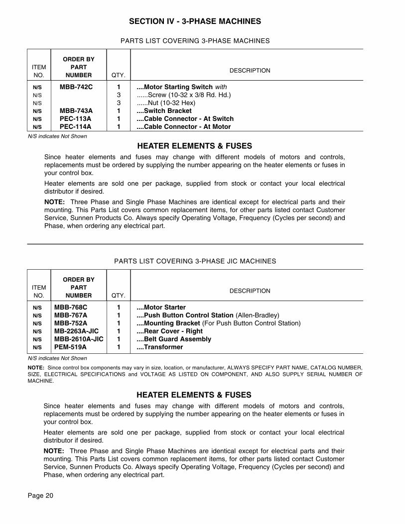
N/S MBB-768C 1 ....Motor Starter N/S MBB-767A 1 ....Push Button Control Station (Allen-Bradley)N/S MBB-752A 1 ....Mounting Bracket (For Push Button Control Station)N/S MB-2263A-JIC 1 ....Rear Cover - RightN/S MBB-2610A-JIC 1 ....Belt Guard AssemblyN/S PEM-519A 1 ....Transformer
PARTS LIST COVERING 3-PHASE JIC MACHINES
N/S indicates Not Shown
HEATER ELEMENTS & FUSESSince heater elements and fuses may change with different models of motors and controls,replacements must be ordered by supplying the number appearing on the heater elements or fuses inyour control box.
Heater elements are sold one per package, supplied from stock or contact your local electricaldistributor if desired.
NOTE: Three Phase and Single Phase Machines are identical except for electrical parts and theirmounting. This Parts List covers common replacement items, for other parts listed contact CustomerService, Sunnen Products Co. Always specify Operating Voltage, Frequency (Cycles per second) andPhase, when ordering any electrical part.
NOTE: Since control box components may vary in size, location, or manufacturer, ALWAYS SPECIFY PART NAME, CATALOG NUMBER,SIZE, ELECTRICAL SPECIFICATIONS and VOLTAGE AS LISTED ON COMPONENT, AND ALSO SUPPLY SERIAL NUMBER OFMACHINE.
SECTION IV - 3-PHASE MACHINES
ITEMNO.
ORDER BYPART
NUMBER QTY.DESCRIPTION
N/S MBB-742C 1 ....Motor Starting Switch withN/S 3 ......Screw (10-32 x 3/8 Rd. Hd.)N/S 3 ......Nut (10-32 Hex)N/S MBB-743A 1 ....Switch BracketN/S PEC-113A 1 ....Cable Connector - At SwitchN/S PEC-114A 1 ....Cable Connector - At Motor
PARTS LIST COVERING 3-PHASE MACHINES
N/S indicates Not Shown
HEATER ELEMENTS & FUSESSince heater elements and fuses may change with different models of motors and controls,replacements must be ordered by supplying the number appearing on the heater elements or fuses inyour control box.
Heater elements are sold one per package, supplied from stock or contact your local electricaldistributor if desired.
NOTE: Three Phase and Single Phase Machines are identical except for electrical parts and theirmounting. This Parts List covers common replacement items, for other parts listed contact CustomerService, Sunnen Products Co. Always specify Operating Voltage, Frequency (Cycles per second) andPhase, when ordering any electrical part.
Like any machinery, this equipment may bedangerous if used improperly. Be sure to readand follow the instructions for the operation ofthe equipment.
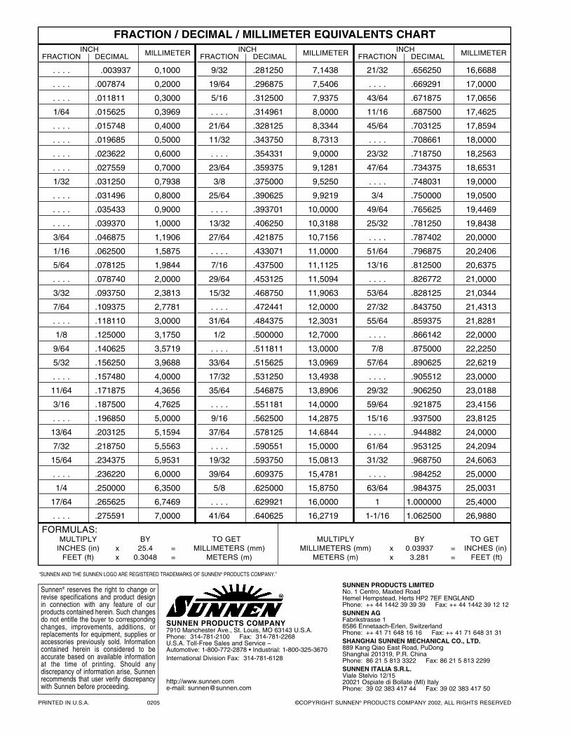
FRACTION / DECIMAL / MILLIMETER EQUIVALENTS CHARTINCH
FRACTION DECIMAL MILLIMETER
. . . . .003937 0,1000
. . . . .007874 0,2000
. . . . .011811 0,3000
1/64 .015625 0,3969
. . . . .015748 0,4000
. . . . .019685 0,5000
. . . . .023622 0,6000
. . . . .027559 0,7000
1/32 .031250 0,7938
. . . . .031496 0,8000
. . . . .035433 0,9000
. . . . .039370 1,0000
3/64 .046875 1,1906
1/16 .062500 1,5875
5/64 .078125 1,9844
. . . . .078740 2,0000
3/32 .093750 2,3813
7/64 .109375 2,7781
. . . . .118110 3,0000
1/8 .125000 3,1750
9/64 .140625 3,5719
5/32 .156250 3,9688
. . . . .157480 4,0000
11/64 .171875 4,3656
3/16 .187500 4,7625
. . . . .196850 5,0000
13/64 .203125 5,1594
7/32 .218750 5,5563
15/64 .234375 5,9531
. . . . .236220 6,0000
1/4 .250000 6,3500
17/64 .265625 6,7469
. . . . .275591 7,0000
INCHFRACTION DECIMAL MILLIMETER
9/32 .281250 7,1438
19/64 .296875 7,5406
5/16 .312500 7,9375
. . . . .314961 8,0000
21/64 .328125 8,3344
11/32 .343750 8,7313
. . . . .354331 9,0000
23/64 .359375 9,1281
3/8 .375000 9,5250
25/64 .390625 9,9219
. . . . .393701 10,0000
13/32 .406250 10,3188
27/64 .421875 10,7156
. . . . .433071 11,0000
7/16 .437500 11,1125
29/64 .453125 11,5094
15/32 .468750 11,9063
. . . . .472441 12,0000
31/64 .484375 12,3031
1/2 .500000 12,7000
. . . . .511811 13,0000
33/64 .515625 13,0969
17/32 .531250 13,4938
35/64 .546875 13,8906
. . . . .551181 14,0000
9/16 .562500 14,2875
37/64 .578125 14,6844
. . . . .590551 15,0000
19/32 .593750 15,0813
39/64 .609375 15,4781
5/8 .625000 15,8750
. . . . .629921 16,0000
41/64 .640625 16,2719
INCHFRACTION DECIMAL MILLIMETER
21/32 .656250 16,6688
. . . . .669291 17,0000
43/64 .671875 17,0656
11/16 .687500 17,4625
45/64 .703125 17,8594
. . . . .708661 18,0000
23/32 .718750 18,2563
47/64 .734375 18,6531
. . . . .748031 19,0000
3/4 .750000 19,0500
49/64 .765625 19,4469
25/32 .781250 19,8438
. . . . .787402 20,0000
51/64 .796875 20,2406
13/16 .812500 20,6375
. . . . .826772 21,0000
53/64 .828125 21,0344
27/32 .843750 21,4313
55/64 .859375 21,8281
. . . . .866142 22,0000
7/8 .875000 22,2250
57/64 .890625 22,6219
. . . . .905512 23,0000
29/32 .906250 23,0188
59/64 .921875 23,4156
15/16 .937500 23,8125
. . . . .944882 24,0000
61/64 .953125 24,2094
31/32 .968750 24,6063
. . . . .984252 25,0000
63/64 .984375 25,0031
1 1.000000 25,4000
1-1/16 1.062500 26,9880
FORMULAS:MULTIPLY BY TO GET MULTIPLY BY TO GET
INCHES (in) x 25.4 = MILLIMETERS (mm) MILLIMETERS (mm) x 0.03937 = INCHES (in)FEET (ft) x 0.3048 = METERS (m) METERS (m) x 3.281 = FEET (ft)
PRINTED IN U.S.A. 0205 ©COPYRIGHT SUNNEN® PRODUCTS COMPANY 2002, ALL RIGHTS RESERVED
SUNNEN PRODUCTS COMPANY7910 Manchester Ave., St. Louis, MO 63143 U.S.A.Phone: 314-781-2100 Fax: 314-781-2268U.S.A. Toll-Free Sales and Service –Automotive: 1-800-772-2878 • Industrial: 1-800-325-3670International Division Fax: 314-781-6128
http://www.sunnen.come-mail: [email protected]
SUNNEN PRODUCTS LIMITEDNo. 1 Centro, Maxted RoadHemel Hempstead, Herts HP2 7EF ENGLANDPhone: ++ 44 1442 39 39 39 Fax: ++ 44 1442 39 12 12SUNNEN AGFabrikstrasse 18586 Ennetaach-Erlen, SwitzerlandPhone: ++ 41 71 648 16 16 Fax: ++ 41 71 648 31 31SHANGHAI SUNNEN MECHANICAL CO., LTD.889 Kang Qiao East Road, PuDongShanghai 201319, P.R. ChinaPhone: 86 21 5 813 3322 Fax: 86 21 5 813 2299SUNNEN ITALIA S.R.L.Viale Stelvio 12/1520021 Ospiate di Bollate (MI) ItalyPhone: 39 02 383 417 44 Fax: 39 02 383 417 50
Sunnen® reserves the right to change orrevise specifications and product designin connection with any feature of ourproducts contained herein. Such changesdo not entitle the buyer to correspondingchanges, improvements, additions, orreplacements for equipment, supplies oraccessories previously sold. Informationcontained herein is considered to beaccurate based on available informationat the time of printing. Should any discrepancy of information arise, Sunnenrecommends that user verify discrepancywith Sunnen before proceeding.
“SUNNEN AND THE SUNNEN LOGO ARE REGISTERED TRADEMARKS OF SUNNEN® PRODUCTS COMPANY.”