Embed Size (px)
Citation preview
Repair of Pre-cracked Reinforced Concrete (RC) Beamswith Openings Strengthened Using FRP Sheets Under Sustained Load
Bashir H. Osman1,2),*, Erjun Wu1), Bohai Ji1), and Suhaib S. Abdulhameed1)
(Received April 22, 2016, Accepted November 17, 2016, Published online February 28, 2017)
Abstract: Strengthening reinforced concrete (RC) beams with openings by using aramid fiber reinforcement polymers (AFRP)
on the beams’ surfaces offers a useful solution for upgrading concrete structures to carry heavy loads. This paper presents a
repairing technique of the AFRP sheets that effectively strengthens RC beams, controls both the failure modes and the stress
distribution around the beam chords and enhances the serviceability (deflection produced under working loads be sufficiently small
and cracking be controlled) of pre-cracked RC beams with openings. To investigate the possible damage that was caused by the
service load and to simulate the structure behavior in the site, a comprehensive experimental study was performed. Two un-
strengthened control beams, four beams that were pre-cracked before the application of the AFRP sheets and one beam that was
strengthened without pre-cracking were tested. Cracking was first induced, followed by repair using various orientations of AFRP
sheets, and then the beams were tested to failure. This load was kept constant during the strengthening process. The results show
that both the preexisting damage level and the FRP orientation have a significant effect on strengthening effectiveness and failure
mode. All of the strengthened specimens exhibited higher capacities with capacity enhancements ranging from 21.8 to 66.4%, and
the crack width reduced by 25.6–82.7% at failure load compared to the control beam. Finally, the authors present a comparison
between the experimental results and the predictions using the ACI 440.2R-08 guidelines.
Keywords: pre-cracked, RC beaam, AFRP strengthening, beam with openings.
1. Introduction
Transverse openings in reinforced concrete (RC) beamsare facilities that allow for the passage of utility linesthrough a structure. Due to sudden changes presented in thecross section of the beam, the opening edges are, for themost part, subjected to high stress concentrations, whichinadvertently leads to induced transverse cracks in the beam;resulting in a significant reduction in the beam shear capacityand stiffness (Mansur 1998; Mansur et al. 1999; Yang et al.2006). The external bonding of different materials, such ashigh–strength fiber reinforced plastics (FRP) or steel plates,has gained wide popularity in recent years to strengthen theRC structural (Hawileh et al. 2012).In recent years, FRP has been increasingly used as a sub-
stitute for traditional steel reinforcements in RC structuresdue to its superior material properties, such as; light weight,immunity to the corrosive effects of acids, alkalis, salts and
similar aggressive materials under wide range of tempera-ture, and excellent mechanical strength and stiffness (Deb-orah 1994). These advantages account for the FRP‘s superiorstrength when compared with alternative materials such assteel plates, steel rods or FRP reinforcing bars (rebars) (Linand Zhang 2013). Furthermore, it has been found that theorientation of the FRP also plays a significant role in thebehavior of RC beams and failure mode (Singh 2013). Theexternal plate bonding technique for structural rehabilitationis now well established as a convenient repair method forincreasing the shear strength and stiffness of reinforcedconcrete beams. The advantage of this technique is the speedof the upgrading process, which makes the technique moreeconomical in most cases compared with other strengtheningtechniques, such as concrete jacketing or complete replace-ment of the member. More importantly, this repair techniquecan be performed while the structure is still in use (Husseinet al. 2013). Within the past decade, there has been numerousstudies conducted regarding the strength and behavior of RCdeep beams with openings (Ashour and Rishi 2000; Cam-pione and Minafo 2012; El Maaddawy and Sherif 2009;Mansur and Alwis 1984; Shanmugam and Swaddiwud-hipong 1988; Zhang et al. 2004). Hussain and Pimanmas(2015) conducted an extensive experimental program toelevate the shear strength of RC deep beams with openingsstrengthened with Sprayed Glass Fiber Reinforced Polymer(SGFRP) composites. Both circular and square openings ofvarying sizes were investigated. To prevent debonding
1)College of Civil and Transportation Engineering, Hohai
University, Nanjing 210098, China.
*Corresponding Author; E-mail: [email protected])Civil Engineering Department, College of Engineering,
University of Sinnar, Sinnar, Sudan.
Copyright � The Author(s) 2017. This article is published
with open access at Springerlink.com
International Journal of Concrete Structures and MaterialsVol.11, No.1, pp.171–183, March 2017DOI 10.1007/s40069-016-0182-3ISSN 1976-0485 / eISSN 2234-1315
171
failures, a mechanical anchoring system was introduced tosecure the SGFRP to the beam‘s surface. They reported thatthe failure mode was changed from debonding to inclinedcrack rupture in the fibers due to the presence of anchor bolts.Alternatively, El Maaddawy and Sherif (2009) examined thepotential use of externally bonded carbon fiber reinforcedpolymer (CFRP) composite sheets as a strengthening solu-tion to upgrade reinforced concrete (RC) deep beams withopenings. The strength gain caused by the CFRP sheets wasin the range of 35–73%. Furthermore, others studies havereported a significant increase in both shear strength andstiffness when the RC deep beams with openings are bondedby fiber reinforced polymer (FRP) system; whilst limiting theresulting shear crack width within these beams (Chaallalet al. 2002; Dias and Barros 2008; Etman 2011; Hoult andLees 2009). The results of these investigations havedemonstrated the effectiveness of different opening geome-tries and different FRP systems such as sheet, wrap and stripsto attain the desired effects. It should be noted that moststudies presented in literature focus on the shear behavior andstrength of RC shallow beams with openings (Mansur 2006;Osman et al. 2016; Torunbalci 2002; Aykac et al. 2013).Two different pre-repair loading histories in RC beams
were simulated by Richardson and Fam (2014) using crackingwithin the elastic range and overloading in the plastic range.Their beams were repaired with either high or ultrahighmodulus (210 or 400 GPa) carbon fiber reinforced polymer(CFRP) sheets or a hybrid sheet and were then reloaded tofailure. Alternatively, tests conducted by El-Ashkar et al.(2012) showed that loading the beams to their first crackingloads before the application of FRP sheets strengthening hasvirtually no effect on the repair efficiency; however, no dis-cussions were found on the effect of increasing the preloadinglevel and the associated increase in crack width and length.The experimental and FE-method-based studies modeling theeffect of various pre-cracked loads on the shear behavior ofFRP-strengthened RC deep beams with openings are scarce.However, very few researchers have considered pre-crackedRC beams that have been strengthened in terms of shear viaexternally bonded FRP reinforcement (Dirar et al. 2013;Vecchio and Bucci 1999; Kim and Vecchio 2008).Accordingly, no researchers have investigated the poten-
tial use of an externally bonded AFRP system as an externalrepair upgrade of pre-cracked RC deep beams with openingsunder sustained load. This paper demonstrates that theAFRP-strengthening sheets can significantly increase theefficiency of pre-cracked RC deep beam with openings. Theexperimental data provided by this paper helps to gain abetter understanding and enhance the experimental databaseof the shear behavior of preloaded RC deep beams withopenings strengthened with the AFRP sheet.
2. Experimental Program
For the experimental investigation, seven rectangularreinforced concrete beams with openings (the openings were
created before concrete casting using circular tubes) werefabricated and tested. Two un-strengthened control beamswere considered, four beams that were pre-cracked beforethe application of the AFRP sheets and one beam that wasstrengthened without pre-cracking were tested. Cracking wasfirst induced, and then repairs were performed using anepoxy injection with varying orientations of the AFRPsheets, followed by testing of the beams to failure. This loadwas kept constant during the strengthening process till fullcuring of the AFRP epoxy adhesive; once the epoxy hadcured, it was continuously loaded till failure of the beam.The following sections provide details of the experimentalprogram.
2.1 Test Specimens and ParametersIn this paper, a total of seven RC deep beam specimens
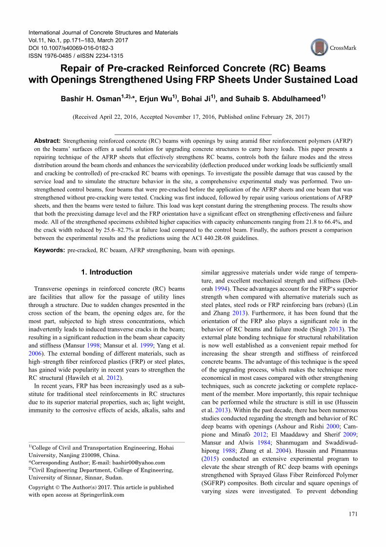
with circular openings were tested. The specimens includedfive repaired beams and two control beams (solid and withopening) without strengthening. All specimens had a rect-angular cross section of 120 mm wide and 300 mm high,with a total length of 1800 mm. All beams were tested undera shear span-to-depth ratio of 1.6 in order to ensure that deepbeam action will develop. The specimens had a similardefault internal shear reinforcement that was designed toensure failure in shear. To guarantee that shear failure wouldoccur only within the shear span of all of the beams, theinternal longitudinal reinforcement (tension steel) wasincreased in the bottom of the beam. Steel stirrups of 6-mm-diameter spaced every 100 mm were implemented as shearreinforcement. All tension and compression reinforcementwere kept the same for all the specimens. Two of the 20-mmdiameter deformed bars were used as bottom reinforcement(in tension the face), and two of 10 mm deformed bars wereused as top reinforcement. Details and dimensions (in mm)of the test beams are shown in Fig. 1.A clear cover at the top and bottom of the beam was
20 mm, whereas a clear cover of 15 mm was maintained onthe beam’s vertical sides. All specimens had two circularopenings, one in each shear span, that were placed sym-metrically about the mid-point of the beam (Fig. 1). Theopening size was 140 mm, which corresponded to openingheight-to-effective depth ratio of 0.5. The beams were cast ina horizontal position using plywood molds.Table 1 summarizes the test matrix, including various
parameters. Specimen B1 and B2 were considered controlbeams and were tested to failure load without any damagingor AFRP strengthening, and B3 was strengthened withAFRP sheets and loaded to failure without preloading.Specimens B4 and B5 were brought to a damage levelwithin the elastic range by cracking up to 50% of the failureload of the control beam (B2) and were then strengthenedwith different AFRP schemes. Beam B6 was strengthenedwith AFRP after being loaded up to 70% of B2, and beamB7 was loaded as in beam B6, but the load was released tothe cracking load of the control beam (B2). The load waskept constant during the strengthening process in beams B4-B7. The strengthening process was took at least three days
172 | International Journal of Concrete Structures and Materials (Vol.11, No.1, March 2017)
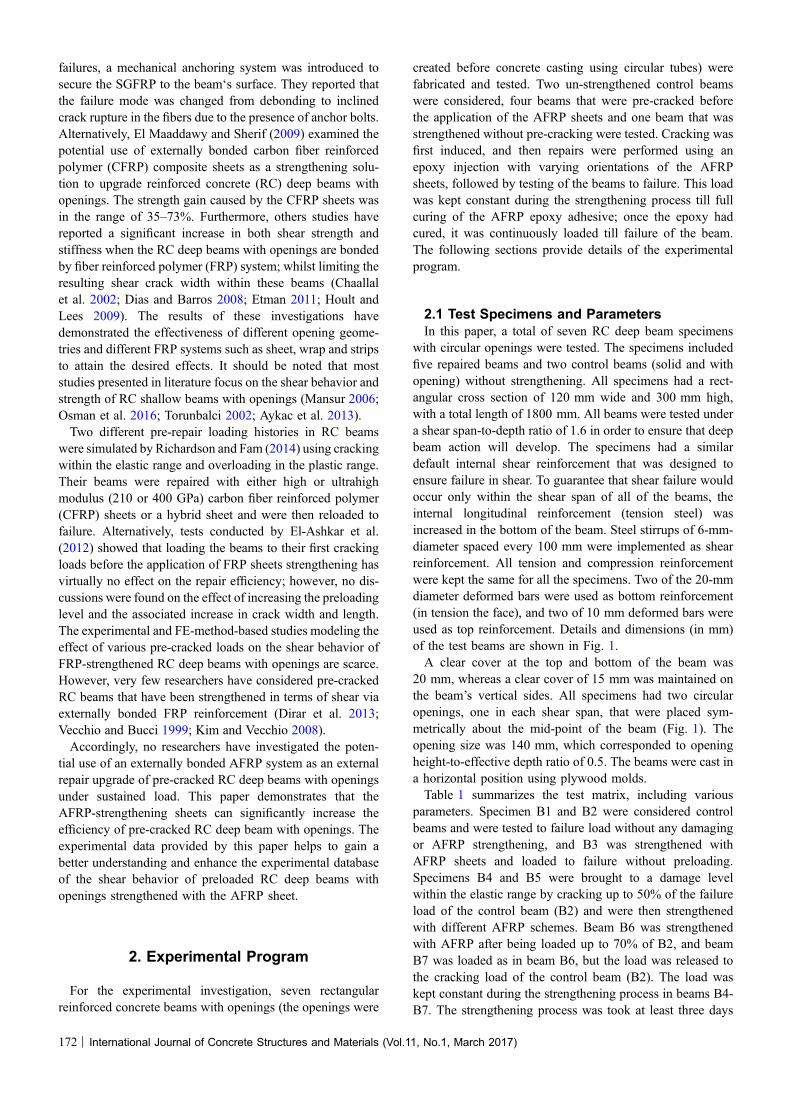
(72 h) to ensure full curing of AFRP epoxy (Abdulhameedet al. 2013).The AFRP sheets were applied to three faces of the beam
in a U wrap shape and had a consistent bond length of350 mm, a 120 mm width and a 300 mm height. SpecimensB3 and B4 were strengthened with vertical AFRP, and thediagonal AFRP (60�) was used in the other beams (B5-B7).Figure 2 presents the layout of the AFRP sheet arrangementson the beam faces.
2.2 Materials’ PropertiesThe properties of the steel reinforcement and the concrete
that were used in this research were obtained experimentally.All test beams were prepared at the same time and curedunder the same conditions to ensure that the compressivestrength was approximate in nature. The cube‘s compressivestrength was obtained by testing nine cubes with dimensionsof 150 9 150 9 150 mm using Compressive TestingMachine (CTM).The average tested compressive strength of
Fig. 1 Specimen’s details (in mm).
Table 1 Test matrix.
No Damage level FRP strengthening FRP orientation F0c (N/mm2) Opening size mm
B1 – – – 39.3 –
B2 – – – 39.3 0.5d
B3 – U wrap Vertical 39.3 0.5d
B4 50% of B2 U wrap Vertical 39.3 0.5d
B5 50% of B2 U wrap Diagonal 39.3 0.5d
B6 70% of B2 U wrap Diagonal 39.3 0.5d
B7 70% of B2 U wrap Diagonal 39.3 0.5d
Fig. 2 AFRP layout a U wrap vertical strengthening (B3 and B4), b U wrap diagonal strengthening (B5-B7).
International Journal of Concrete Structures and Materials (Vol.11, No.1, March 2017) | 173
concrete at 28 days was 39.3 MPa. The yield strength ofsteel reinforcement was obtained by testing three bars withdiameters of /20 mm, /10 mm and /6 mm, respectively,using Tensile Testing Machine (TTM). The longitudinal steelreinforcement was Grade 480 and 450 deformed steel barsfor tension (/20 mm) and compression (/10 mm) rein-forcement, respectively, and the web reinforcement wasGrade 330 deformed bars. The AFRP sheet (type C1-AK-40)has a tensile strength of 2100 MPa, an elastic modulus of120 GPa, and a thickness of 0.193 mm. The properties of theepoxy adhesive, primer, putty, and FRP were provided bythe manufacturers and are given in Table 2.
2.3 Specimen Preparations and Test SetupThe concrete surface was prepared before the bonding of
the U-shaped AFRP sheets. The three surfaces of the beamwere sandblasted and cleaned before FRP application untilthe aggregates were exposed. The corners of the beam wererounded with a radius of 10 mm to avoid stress concentra-tion in the U wrap. Longitudinal AFRP sheets that were60 mm wide by 350 mm long were bonded to the concretechords above and below each opening, with the fibers ori-ented in a direction parallel to the longitudinal axis of thebeam (Fig. 2) to prevent any delamination occurring duringshear that would have concentrated in the chords.The surface dust was removed by an air blower. Next, the
surface was cleaned with acetone. A thin layer of primer[type Telesun Epoxy Adhesive (TLS)-501] was applied tothe prepared surface of the reinforced concrete beam. Theprimer was allowed to cure for 24 h before the epoxyadhesive was applied to the concrete. The purposes of theprimer are as follows: to strengthen the surface of the con-crete, prevent the epoxy from being absorbed by the concreteinstead of wetting fibers, penetrate the concrete via the pores,and enhance the bond for the fibers. Putty is used to filllarger holes and irregularities on the surface of the concrete.A layer of epoxy adhesive (TLS-503) was applied by apaintbrush to the surface of the concrete and AFRP sheet(Abdulhameed et al. 2013).All beams were tested under four-point bending in the
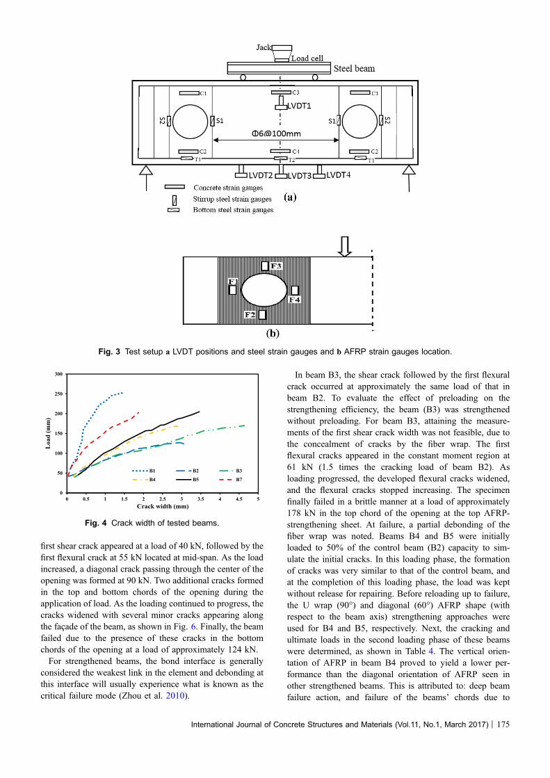
structural testing frame, as shown in Fig. 3. To providebearing and frictionless rotational, the beams were supportedon two heavy-duty rollers during the test. The clear spanbetween the supports was 1500 mm. The beams were sub-jected to two monotonic loadings using a steel spreader
beam that conveyed the load from a 500-kN capacity jack tothe beam. The load was measured by a 500-kN capacity loadcell. The load was applied at an increment of 5 kN using theload cell machine. The distance between the loads was600 mm. The deflection values were recorded at each loadincrement up to failure. The load that caused the crack wasrecorded, and its crack pattern was marked on the beamsurfaces (Fig. 4).
2.4 Instrumentation of LVDTs and StrainGaugesThe tested RC beams were instrumented with linear
variable differential transducers (LVDTs) to monitor thedeflection and the crack width during the test (Fig. 3). Thedeflection during testing was measured using LVDTs locatedunder the two load points and at mid-span. Measurements ofthe strains in the reinforcing bars and concrete were madeusing electrical-resistance strain gauges with gauge lengthsof 5 and 100 mm, respectively, as shown in Fig. 3a. Strainsin the AFRP were made using electrical-resistance straingauges with gauge lengths of 5 mm, as shown in Fig. 3b.
3. Experimental Results and Discussions
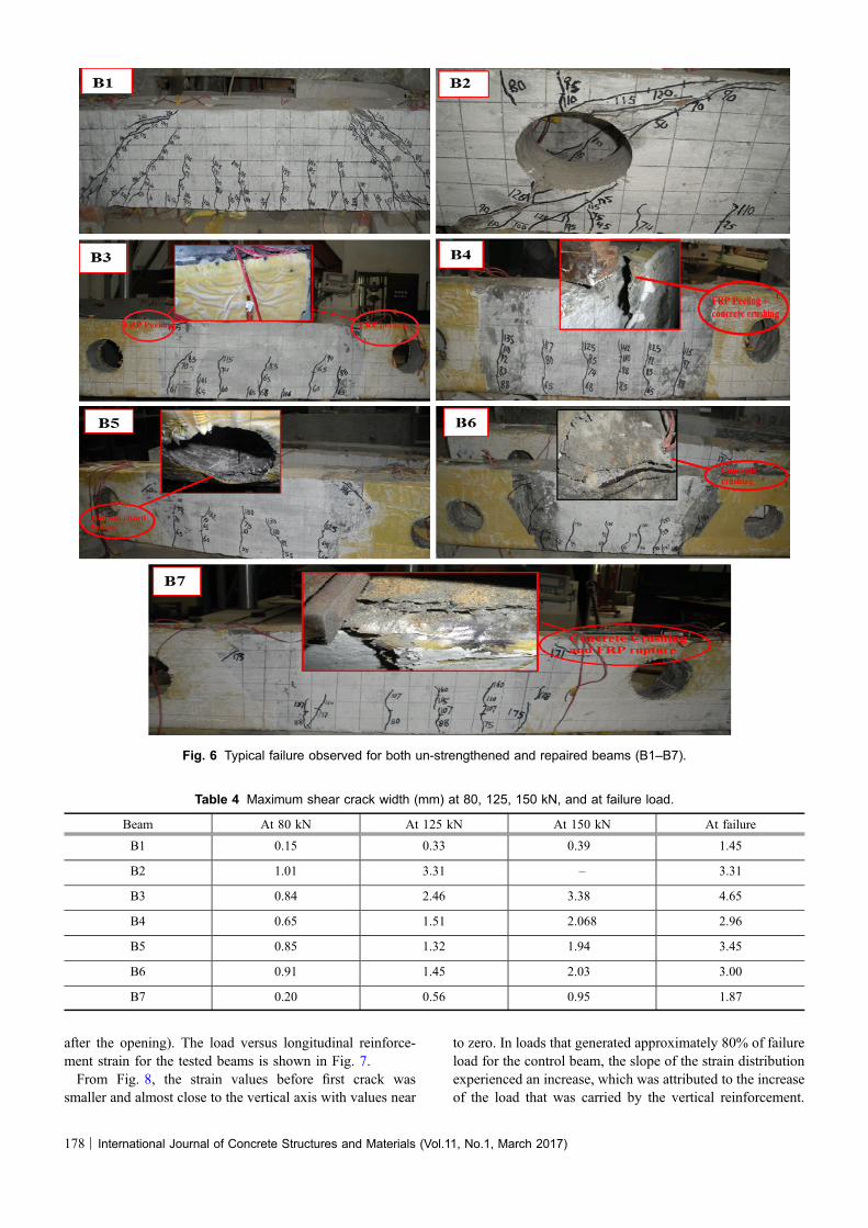
3.1 Failure Mode and Cracks PatternTable 3 gives a summary of the load capacity and failure
modes of all of the tested beams. The observation of spec-imens during the tests and detailed discussions are presentedin the following. It was noted that the control beam B1experienced failure due to the shearing off of the concrete inthe load path, located between the load points and the sup-ports, as illustrated in Fig. 6. As the load increased, inclineddiagonal shear cracks (at approximately 45� from the sup-ports) appeared at the line connecting the load points and thesupports. A further load increase resulted in the widening ofdiagonal cracks as well as the initiation of new flexural anddiagonal cracks, whereas the shear cracks were inactive. Dueto failure in the shear region, the beam finally failed at a loadof 251 kN. The load-mid-span deflection curve and thefailure mode of the beam are illustrated in Figs. 5 and 6,respectively.Beam B2, which was tested to failure without strength-
ening, failed at a load 50% lower than that of the controlbeam B1. Failure occurred by shear off of the concrete. The
Table 2 Material Properties.
Material Tensile strength(MPa)
Bond strength(MPa)
Ultimate strain (%) Elastic modulus(GPa)
Mixing ratio Curing time (h)
Putty (TLS-502) C30 CMax (2.5, ftk) – – 3:1 24
Primer (TLS-501) – CMax (2.5, ftk) – – 4:1 24
Epoxy (TLS-503) C40 CMax (2.5, ftk) C1.5 C2500 4:1 72
Material Type Areal density (g/m2) Ultimate tensilestrength (MPa)
Modulus (GPa) Thickness (mm)
AFRP C1-AK-40 280 2100 120 0.193
174 | International Journal of Concrete Structures and Materials (Vol.11, No.1, March 2017)
first shear crack appeared at a load of 40 kN, followed by thefirst flexural crack at 55 kN located at mid-span. As the loadincreased, a diagonal crack passing through the center of theopening was formed at 90 kN. Two additional cracks formedin the top and bottom chords of the opening during theapplication of load. As the loading continued to progress, thecracks widened with several minor cracks appearing alongthe facade of the beam, as shown in Fig. 6. Finally, the beamfailed due to the presence of these cracks in the bottomchords of the opening at a load of approximately 124 kN.For strengthened beams, the bond interface is generally
considered the weakest link in the element and debonding atthis interface will usually experience what is known as thecritical failure mode (Zhou et al. 2010).
In beam B3, the shear crack followed by the first flexuralcrack occurred at approximately the same load of that inbeam B2. To evaluate the effect of preloading on thestrengthening efficiency, the beam (B3) was strengthenedwithout preloading. For beam B3, attaining the measure-ments of the first shear crack width was not feasible, due tothe concealment of cracks by the fiber wrap. The firstflexural cracks appeared in the constant moment region at61 kN (1.5 times the cracking load of beam B2). Asloading progressed, the developed flexural cracks widened,and the flexural cracks stopped increasing. The specimenfinally failed in a brittle manner at a load of approximately178 kN in the top chord of the opening at the top AFRP-strengthening sheet. At failure, a partial debonding of thefiber wrap was noted. Beams B4 and B5 were initiallyloaded to 50% of the control beam (B2) capacity to sim-ulate the initial cracks. In this loading phase, the formationof cracks was very similar to that of the control beam, andat the completion of this loading phase, the load was keptwithout release for repairing. Before reloading up to failure,the U wrap (90�) and diagonal (60�) AFRP shape (withrespect to the beam axis) strengthening approaches wereused for B4 and B5, respectively. Next, the cracking andultimate loads in the second loading phase of these beamswere determined, as shown in Table 4. The vertical orien-tation of AFRP in beam B4 proved to yield a lower per-formance than the diagonal orientation of AFRP seen inother strengthened beams. This is attributed to: deep beamfailure action, and failure of the beams’ chords due to
Fig. 3 Test setup a LVDT positions and steel strain gauges and b AFRP strain gauges location.
0
50
100
150
200
250
300
0 0.5 1 1.5 2 2.5 3 3.5 4 4.5 5
Loa
d (m
m)
Crack width (mm)
B1 B2 B3
B4 B5 B7
Fig. 4 Crack width of tested beams.
International Journal of Concrete Structures and Materials (Vol.11, No.1, March 2017) | 175
vertical cracks parallel to the FRP axis which helps forFRP peeling.Beams B6 and B7 were initially loaded up to 70% of the
control beam (B2) capacity to simulate the initial cracks.The load in Beam B6 was kept without release, whereas,the load in B7 was released to the cracking load of controlbeam B2. The load was then kept constant for both beamsduring FRP strengthening process. The diagonal AFRPstrips were then used to strengthen both the upper andlower chords of these beams. After this strengtheningprocedure, the beams were subjected to a continuous load.It was observed that there were no critical diagonal crackspresent in beams B6 and B7; the maximum crack widthmeasured for these beams, therefore, remained minor dur-ing the entire loading history. Additionally, when comparedto beam B4, no debonding failure was observed at the endof the AFRP in these beams up to the failure loads. Thecracking, failure loads and modes of failure of these beamsare shown in Table 3 and Fig. 6. Compared to beam B1,the reduction in shear capacity was caused by the earlyformation of a diagonal crack around the chords of theopening due to the stress concentration and the reducedability of the web area to resist high shear.
3.2 Cracking BehaviorsA special microscope with 0.02-mm accuracy was used to
measure the crack width at different locations. The loadscorresponding to the appearance and progression of cracks atthe different loading stages are presented in Table 4. Thefirst crack appeared at approximately the shear span of thebeam, with, new cracks forming progressively towards thesupports. Diagonal shear cracks appeared next, which werepropagated downwards to the inner edge of the support andupwards to the loading point. With its appearance, the widthof the shear cracks began to exceed that of those formed inthe flexural zone. As load increased, the existing cracksadvanced further and new cracks began to form inside theopenings, which ultimately lead to the failure at the beam‘schords. During the course of this study, all major crackswere inspected (visually) and their maximum widths
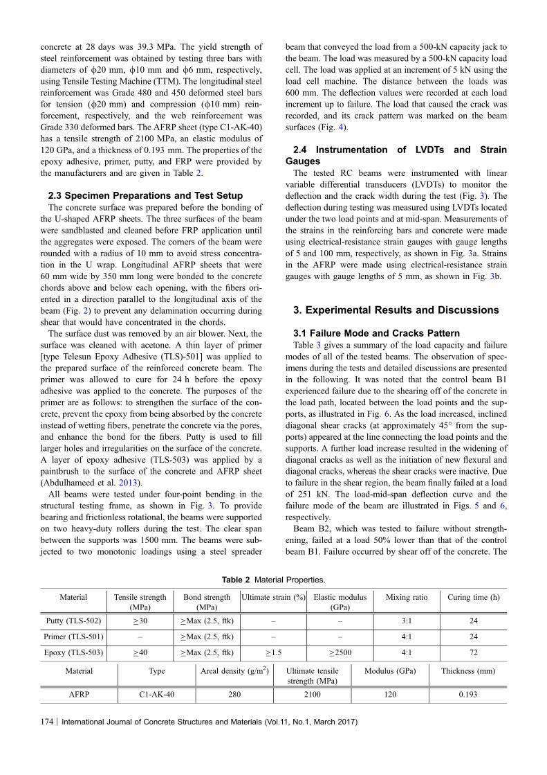
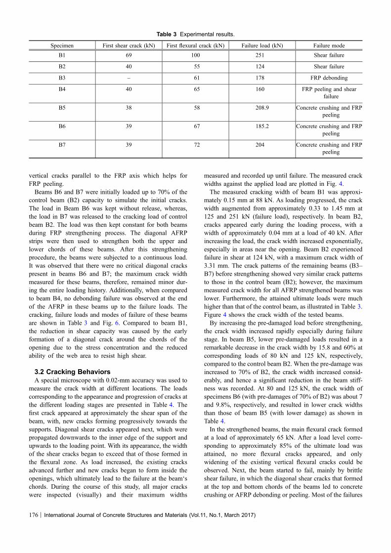
measured and recorded up until failure. The measured crackwidths against the applied load are plotted in Fig. 4.The measured cracking width of beam B1 was approxi-
mately 0.15 mm at 88 kN. As loading progressed, the crackwidth augmented from approximately 0.33 to 1.45 mm at125 and 251 kN (failure load), respectively. In beam B2,cracks appeared early during the loading process, with awidth of approximately 0.04 mm at a load of 40 kN. Afterincreasing the load, the crack width increased exponentially,especially in areas near the opening. Beam B2 experiencedfailure in shear at 124 kN, with a maximum crack width of3.31 mm. The crack patterns of the remaining beams (B3–B7) before strengthening showed very similar crack patternsto those in the control beam (B2); however, the maximummeasured crack width for all AFRP strengthened beams waslower. Furthermore, the attained ultimate loads were muchhigher than that of the control beam, as illustrated in Table 3.Figure 4 shows the crack width of the tested beams.By increasing the pre-damaged load before strengthening,
the crack width increased rapidly especially during failurestage. In beam B5, lower pre-damaged loads resulted in aremarkable decrease in the crack width by 15.8 and 60% atcorresponding loads of 80 kN and 125 kN, respectively,compared to the control beam B2. When the pre-damage wasincreased to 70% of B2, the crack width increased consid-erably, and hence a significant reduction in the beam stiff-ness was recorded. At 80 and 125 kN, the crack width ofspecimens B6 (with pre-damages of 70% of B2) was about 7and 9.8%, respectively, and resulted in lower crack widthsthan those of beam B5 (with lower damage) as shown inTable 4.In the strengthened beams, the main flexural crack formed
at a load of approximately 65 kN. After a load level corre-sponding to approximately 85% of the ultimate load wasattained, no more flexural cracks appeared, and onlywidening of the existing vertical flexural cracks could beobserved. Next, the beam started to fail, mainly by brittleshear failure, in which the diagonal shear cracks that formedat the top and bottom chords of the beams led to concretecrushing or AFRP debonding or peeling. Most of the failures
Table 3 Experimental results.
Specimen First shear crack (kN) First flexural crack (kN) Failure load (kN) Failure mode
B1 69 100 251 Shear failure
B2 40 55 124 Shear failure
B3 – 61 178 FRP debonding
B4 40 65 160 FRP peeling and shearfailure
B5 38 58 208.9 Concrete crushing and FRPpeeling
B6 39 67 185.2 Concrete crushing and FRPpeeling
B7 39 72 204 Concrete crushing and FRPpeeling
176 | International Journal of Concrete Structures and Materials (Vol.11, No.1, March 2017)
of the tested beams occurred in the concrete thin layeradjacent to the sheet (in direct contact with the FRP sheet),not in the adhesive epoxy (Fig. 6) (Hussein et al. 2013).
3.3 Deflection BehaviorTo investigate the deflections and stiffness of the rein-
forced concrete beams with openings strengthened withAFRP sheets, the load deflection curves were studied. Four
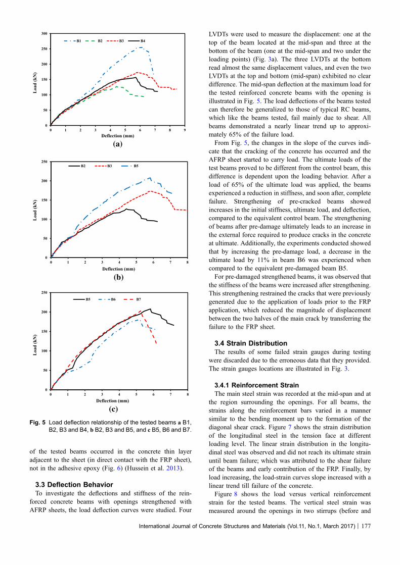
LVDTs were used to measure the displacement: one at thetop of the beam located at the mid-span and three at thebottom of the beam (one at the mid-span and two under theloading points) (Fig. 3a). The three LVDTs at the bottomread almost the same displacement values, and even the twoLVDTs at the top and bottom (mid-span) exhibited no cleardifference. The mid-span deflection at the maximum load forthe tested reinforced concrete beams with the opening isillustrated in Fig. 5. The load deflections of the beams testedcan therefore be generalized to those of typical RC beams,which like the beams tested, fail mainly due to shear. Allbeams demonstrated a nearly linear trend up to approxi-mately 65% of the failure load.From Fig. 5, the changes in the slope of the curves indi-
cate that the cracking of the concrete has occurred and theAFRP sheet started to carry load. The ultimate loads of thetest beams proved to be different from the control beam, thisdifference is dependent upon the loading behavior. After aload of 65% of the ultimate load was applied, the beamsexperienced a reduction in stiffness, and soon after, completefailure. Strengthening of pre-cracked beams showedincreases in the initial stiffness, ultimate load, and deflection,compared to the equivalent control beam. The strengtheningof beams after pre-damage ultimately leads to an increase inthe external force required to produce cracks in the concreteat ultimate. Additionally, the experiments conducted showedthat by increasing the pre-damage load, a decrease in theultimate load by 11% in beam B6 was experienced whencompared to the equivalent pre-damaged beam B5.For pre-damaged strengthened beams, it was observed that
the stiffness of the beams were increased after strengthening.This strengthening restrained the cracks that were previouslygenerated due to the application of loads prior to the FRPapplication, which reduced the magnitude of displacementbetween the two halves of the main crack by transferring thefailure to the FRP sheet.
3.4 Strain DistributionThe results of some failed strain gauges during testing
were discarded due to the erroneous data that they provided.The strain gauges locations are illustrated in Fig. 3.
3.4.1 Reinforcement StrainThe main steel strain was recorded at the mid-span and at
the region surrounding the openings. For all beams, thestrains along the reinforcement bars varied in a mannersimilar to the bending moment up to the formation of thediagonal shear crack. Figure 7 shows the strain distributionof the longitudinal steel in the tension face at differentloading level. The linear strain distribution in the longitu-dinal steel was observed and did not reach its ultimate strainuntil beam failure; which was attributed to the shear failureof the beams and early contribution of the FRP. Finally, byload increasing, the load-strain curves slope increased with alinear trend till failure of the concrete.Figure 8 shows the load versus vertical reinforcement
strain for the tested beams. The vertical steel strain wasmeasured around the openings in two stirrups (before and
(a)
0
50
100
150
200
250
300
0 1 2 3 4 5 6 7 8 9
Loa
d (k
N)
Deflection (mm)
B1 B2 B3 B4
(b)
(c)
0
50
100
150
200
250
0 1 2 3 4 5 6 7 8
Loa
d (k
N)
Deflection (mm)
B2 B3 B5
0
50
100
150
200
250
0 1 2 3 4 5 6 7 8
Loa
d (k
N)
Deflection (mm)
B5 B6 B7
Fig. 5 Load deflection relationship of the tested beams a B1,B2, B3 and B4, b B2, B3 and B5, and c B5, B6 and B7.
International Journal of Concrete Structures and Materials (Vol.11, No.1, March 2017) | 177
after the opening). The load versus longitudinal reinforce-ment strain for the tested beams is shown in Fig. 7.From Fig. 8, the strain values before first crack was
smaller and almost close to the vertical axis with values near
to zero. In loads that generated approximately 80% of failureload for the control beam, the slope of the strain distributionexperienced an increase, which was attributed to the increaseof the load that was carried by the vertical reinforcement.
Fig. 6 Typical failure observed for both un-strengthened and repaired beams (B1–B7).
Table 4 Maximum shear crack width (mm) at 80, 125, 150 kN, and at failure load.
Beam At 80 kN At 125 kN At 150 kN At failure
B1 0.15 0.33 0.39 1.45
B2 1.01 3.31 – 3.31
B3 0.84 2.46 3.38 4.65
B4 0.65 1.51 2.068 2.96
B5 0.85 1.32 1.94 3.45
B6 0.91 1.45 2.03 3.00
B7 0.20 0.56 0.95 1.87
178 | International Journal of Concrete Structures and Materials (Vol.11, No.1, March 2017)
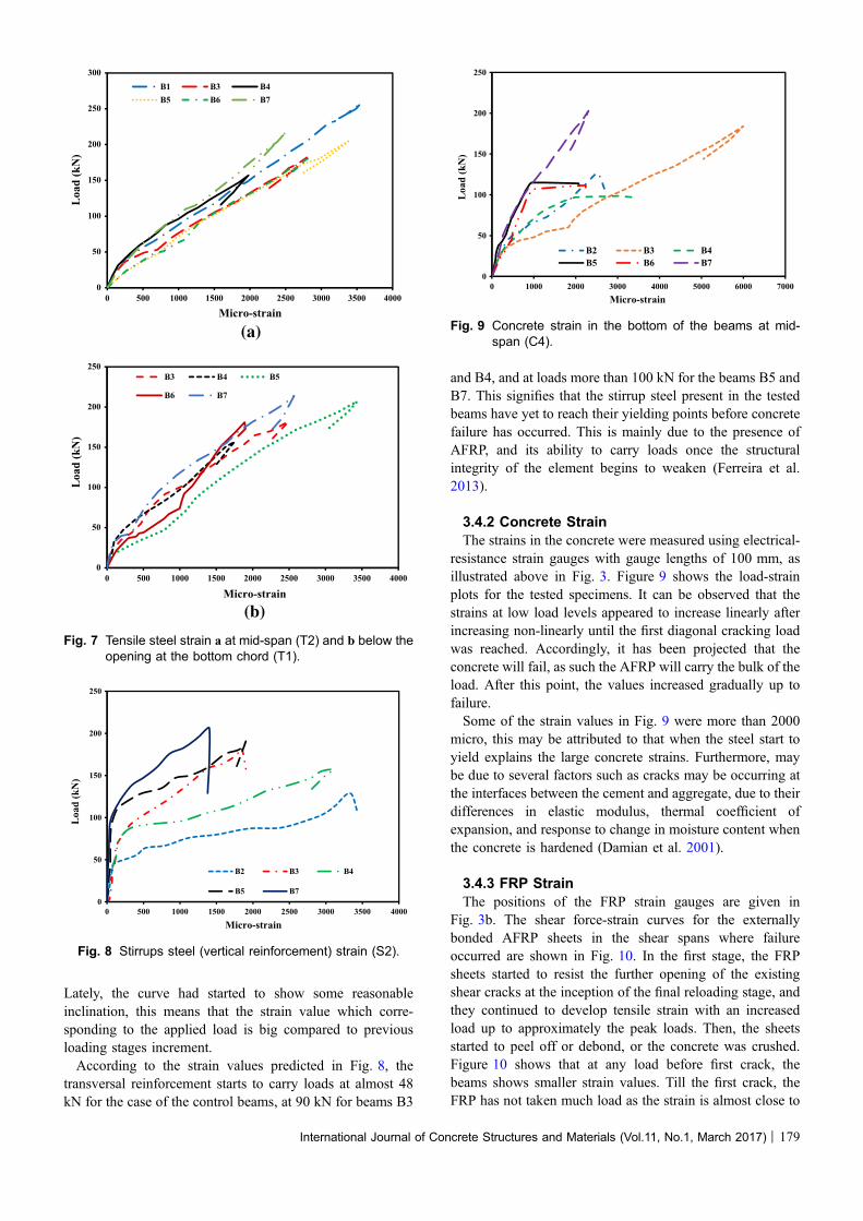
Lately, the curve had started to show some reasonableinclination, this means that the strain value which corre-sponding to the applied load is big compared to previousloading stages increment.According to the strain values predicted in Fig. 8, the
transversal reinforcement starts to carry loads at almost 48kN for the case of the control beams, at 90 kN for beams B3
and B4, and at loads more than 100 kN for the beams B5 andB7. This signifies that the stirrup steel present in the testedbeams have yet to reach their yielding points before concretefailure has occurred. This is mainly due to the presence ofAFRP, and its ability to carry loads once the structuralintegrity of the element begins to weaken (Ferreira et al.2013).
3.4.2 Concrete StrainThe strains in the concrete were measured using electrical-
resistance strain gauges with gauge lengths of 100 mm, asillustrated above in Fig. 3. Figure 9 shows the load-strainplots for the tested specimens. It can be observed that thestrains at low load levels appeared to increase linearly afterincreasing non-linearly until the first diagonal cracking loadwas reached. Accordingly, it has been projected that theconcrete will fail, as such the AFRP will carry the bulk of theload. After this point, the values increased gradually up tofailure.Some of the strain values in Fig. 9 were more than 2000
micro, this may be attributed to that when the steel start toyield explains the large concrete strains. Furthermore, maybe due to several factors such as cracks may be occurring atthe interfaces between the cement and aggregate, due to theirdifferences in elastic modulus, thermal coefficient ofexpansion, and response to change in moisture content whenthe concrete is hardened (Damian et al. 2001).
3.4.3 FRP StrainThe positions of the FRP strain gauges are given in
Fig. 3b. The shear force-strain curves for the externallybonded AFRP sheets in the shear spans where failureoccurred are shown in Fig. 10. In the first stage, the FRPsheets started to resist the further opening of the existingshear cracks at the inception of the final reloading stage, andthey continued to develop tensile strain with an increasedload up to approximately the peak loads. Then, the sheetsstarted to peel off or debond, or the concrete was crushed.Figure 10 shows that at any load before first crack, thebeams shows smaller strain values. Till the first crack, theFRP has not taken much load as the strain is almost close to
(a)
0
50
100
150
200
250
300
0 500 1000 1500 2000 2500 3000 3500 4000
Loa
d (k
N)
Micro-strain
B1 B3 B4B5 B6 B7
(b)
0
50
100
150
200
250
0 500 1000 1500 2000 2500 3000 3500 4000
Loa
d (k
N)
Micro-strain
B3 B4 B5
B6 B7
Fig. 7 Tensile steel strain a at mid-span (T2) and b below theopening at the bottom chord (T1).
0
50
100
150
200
250
0 500 1000 1500 2000 2500 3000 3500 4000
Loa
d (k
N)
Micro-strain
B2 B3 B4
B5 B7
Fig. 8 Stirrups steel (vertical reinforcement) strain (S2).
0
50
100
150
200
250
0 1000 2000 3000 4000 5000 6000 7000
Loa
d (k
N)
Micro-strain
B2 B3 B4B5 B6 B7
Fig. 9 Concrete strain in the bottom of the beams at mid-span (C4).
International Journal of Concrete Structures and Materials (Vol.11, No.1, March 2017) | 179
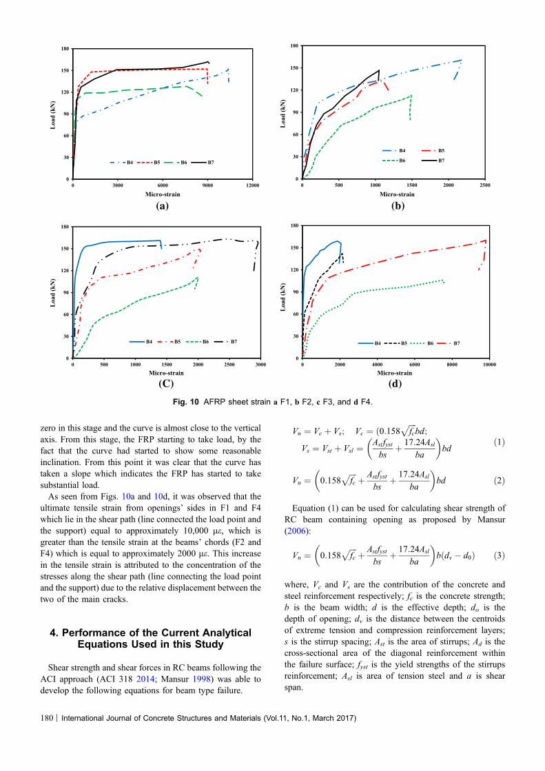
zero in this stage and the curve is almost close to the verticalaxis. From this stage, the FRP starting to take load, by thefact that the curve had started to show some reasonableinclination. From this point it was clear that the curve hastaken a slope which indicates the FRP has started to takesubstantial load.As seen from Figs. 10a and 10d, it was observed that the
ultimate tensile strain from openings’ sides in F1 and F4which lie in the shear path (line connected the load point andthe support) equal to approximately 10,000 le, which isgreater than the tensile strain at the beams’ chords (F2 andF4) which is equal to approximately 2000 le. This increasein the tensile strain is attributed to the concentration of thestresses along the shear path (line connecting the load pointand the support) due to the relative displacement between thetwo of the main cracks.
4. Performance of the Current AnalyticalEquations Used in this Study
Shear strength and shear forces in RC beams following theACI approach (ACI 318 2014; Mansur 1998) was able todevelop the following equations for beam type failure.
Vn ¼ Vc þ Vs; Vc ¼ ð0:158ffiffiffiffi
fcp
bd;
Vs ¼ Vst þ Vsl ¼Astfystbs
þ 17:24Asl
ba
� �
bdð1Þ
Vn ¼ 0:158ffiffiffiffi
fcp
þ Astfystbs
þ 17:24Asl
ba
� �
bd ð2Þ
Equation (1) can be used for calculating shear strength ofRC beam containing opening as proposed by Mansur(2006):
Vn ¼ 0:158ffiffiffiffi
fcp
þ Astfystbs
þ 17:24Asl
ba
� �
b dv � d0ð Þ ð3Þ
where, Vc and Vs are the contribution of the concrete andsteel reinforcement respectively; fc is the concrete strength;b is the beam width; d is the effective depth; do is thedepth of opening; dv is the distance between the centroidsof extreme tension and compression reinforcement layers;s is the stirrup spacing; Ast is the area of stirrups; Ad is thecross-sectional area of the diagonal reinforcement withinthe failure surface; fyst is the yield strengths of the stirrupsreinforcement; Asl is area of tension steel and a is shearspan.
(a)
0
30
60
90
120
150
180
0 3000 6000 9000 12000
Loa
d (k
N)
Micro-strain
B4 B5 B6 B7
(b)
0
30
60
90
120
150
180
0 500 1000 1500 2000 2500
Loa
d (k
N)
Micro-strain
B4 B5
B6 B7
(C) (d)
0
30
60
90
120
150
180
0 500 1000 1500 2000 2500 3000
Loa
d (k
N)
Micro-strain
B4 B5 B6 B7
0
30
60
90
120
150
180
0 2000 4000 6000 8000 10000
Loa
d (k
N)
Micro-strain
B4 B5 B6 B7
Fig. 10 AFRP sheet strain a F1, b F2, c F3, and d F4.
180 | International Journal of Concrete Structures and Materials (Vol.11, No.1, March 2017)
4.1 FRP ContributionThe contribution of the FRP sheet to shear strength of RC
beams is based on the orientation of the fiber and an assumedcrack pattern (ACI-440.2R-08 2008). The shear strengthprovided by the FRP contribution can be determined bycalculating the force resulting from the tensile stress in theFRP across the assumed crack. The shear contribution of theFRP shear reinforcement is given by the following equations(ACI-440.2R-08 2008):
Vf ¼Af ffeðsin aþ cos aÞdf
sfð4Þ
Af ¼ 2ntf wf ð5Þ
ffe ¼ effe � Ef ð6Þ
Shear capacity of FRP RC beam can be determined fromEq. (7).
/Vn ¼ /ðVc þ VsÞ þ 0:7Vf ð7Þ
where / = the strength-reduction factor required by ACIthat for shear strengthening of concrete elements has a valueof 0.85 (Khalifa et al. 1998); sf is the spacing of the wet lay-up strips of FRP sheets; and Afv is the area of FRP shearreinforcement within spacing, sf; tf, n, and wf are the thick-ness of a layer, the number of layers per strip, and the widthof the strips, respectively. If continuous or one FRP sheetsare used, the width of the strip, wf and the spacing of thestrips, sf should be equal (sf = wf) (Khalifa et al. 1998).The effective stress in the FRP, ffe obtained multiplying the
elasticity modulus of the FRP, Ef by the effective strain
efe ¼ kvefu � 0:004 ðfor U-wrapÞ ð8Þ
where, kv is a bond-reduction coefficient that is a function ofthe concrete strength, the type of wrapping scheme used, andthe stiffness of the FRP.
kv ¼k1k2Le
11; 900efu� 0:75 ð9Þ
Le ¼23; 300
ðntf Ef Þ0:58ð10Þ
k1 ¼fc27
� �0:67
ð11Þ
k2 ¼ðdf�LeÞ
dffor U wrapð Þ ð12Þ
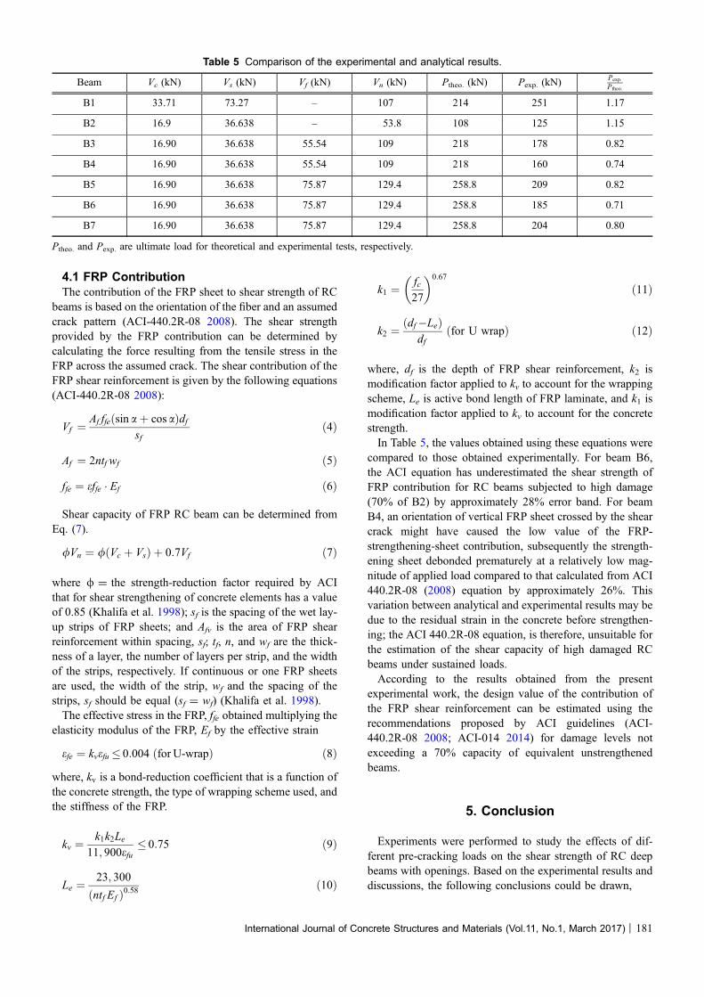
where, df is the depth of FRP shear reinforcement, k2 ismodification factor applied to kv to account for the wrappingscheme, Le is active bond length of FRP laminate, and k1 ismodification factor applied to kv to account for the concretestrength.In Table 5, the values obtained using these equations were
compared to those obtained experimentally. For beam B6,the ACI equation has underestimated the shear strength ofFRP contribution for RC beams subjected to high damage(70% of B2) by approximately 28% error band. For beamB4, an orientation of vertical FRP sheet crossed by the shearcrack might have caused the low value of the FRP-strengthening-sheet contribution, subsequently the strength-ening sheet debonded prematurely at a relatively low mag-nitude of applied load compared to that calculated from ACI440.2R-08 (2008) equation by approximately 26%. Thisvariation between analytical and experimental results may bedue to the residual strain in the concrete before strengthen-ing; the ACI 440.2R-08 equation, is therefore, unsuitable forthe estimation of the shear capacity of high damaged RCbeams under sustained loads.According to the results obtained from the present
experimental work, the design value of the contribution ofthe FRP shear reinforcement can be estimated using therecommendations proposed by ACI guidelines (ACI-440.2R-08 2008; ACI-014 2014) for damage levels notexceeding a 70% capacity of equivalent unstrengthenedbeams.
5. Conclusion
Experiments were performed to study the effects of dif-ferent pre-cracking loads on the shear strength of RC deepbeams with openings. Based on the experimental results anddiscussions, the following conclusions could be drawn,
Table 5 Comparison of the experimental and analytical results.
Beam Vc (kN) Vs (kN) Vf (kN) Vn (kN) Ptheo. (kN) Pexp. (kN)Pexp:
Ptheo:
B1 33.71 73.27 – 107 214 251 1.17
B2 16.9 36.638 – 53.8 108 125 1.15
B3 16.90 36.638 55.54 109 218 178 0.82
B4 16.90 36.638 55.54 109 218 160 0.74
B5 16.90 36.638 75.87 129.4 258.8 209 0.82
B6 16.90 36.638 75.87 129.4 258.8 185 0.71
B7 16.90 36.638 75.87 129.4 258.8 204 0.80
Ptheo. and Pexp. are ultimate load for theoretical and experimental tests, respectively.
International Journal of Concrete Structures and Materials (Vol.11, No.1, March 2017) | 181
(1) The pre-cracked RC deep beams with openingsstrengthened by AFRP sheets displayed a higher levelof stiffness and ductility; with reductions in the crackwidth between 25.6 and 82.7% at failure load whencompared with the control beam. This is predominatelydue to limiting the development of shear cracks byusing the epoxy resin prior to the application of theAFRP strengthening strip. This is demonstrated mostclearly in beam B7, which was loaded up to 70% andreduced to cracking loads of those loads subjected toB2.
(2) Damage levels have an effect on the ultimate capacityof the reinforced concrete deep beam strengthened withAFRP sheet by a decrease in failure load of approx-imately 11.5%, when the damage level was increasedfrom 50 to 70% of control beam B2. Beam B7 failedwith load capacities lower than that of beam B5 by2.5%, this is attributed to the residual stress in beamB7.
(3) All of the strengthened specimens exhibited highercapacities than the equivalent unstrengthened controlbeams, with capacity enhancements ranging from 21.8to 66.4%, thus confirming the potential effectiveness ofthe FRP sheets.
(4) Strengthening the more damaged RC deep beams withopenings by AFRP sheets decreased the mid-spandeflection at the ultimate load by 22.5% whencompared with the control beam. This is primarilydue to the AFRP’s ability to carry additional loadswhen the concrete begins to experience failure and itsability to limit further development of exiting cracks.
(5) AFRP strengthening of pre-cracked RC deep beam withopening can enhances a beam’s capacity (Fig. 5) andstiffness after repairing, and decreases the crack widthspatially (as seen in beam B7). Furthermore, loading thebeams to less than their cracking loads prior to theapplication of the FRP strengthening had almost noeffect on the repair efficiency (El-Ashkar et al. 2012).
(6) The orientation of AFRP sheets used for shearstrengthening (reducing the stress concentration onthe top and bottom chords of the opening) and thecrack width both play a significant role in the behaviorof RC beams with openings. The AFRP sheets installedat 60� to the axis of the beam are found to be mostefficient for shear-strength enhancements, whereas thevertical AFRP sheets are less effective (B4 and B5).
Open Access
This article is distributed under the terms of the CreativeCommons Attribution 4.0 International License(http://creativecommons.org/licenses/by/4.0/), which per-mits unrestricted use, distribution, and reproduction in anymedium, provided you give appropriate credit to the originalauthor(s) and the source, provide a link to the CreativeCommons license, and indicate if changes were made.
References
Abdulhameed, S. S., Wu, E., & Ji, B. (2013). Mechanical pre-
stressing system for strengthening reinforced concrete
members with prestressed carbon-fiber-reinforced polymer
sheets. Journal of Performance of Constructed Facilities,
29(3), 04014081.
ACI-014. (2014). Building code requirements for structural
concrete and commentary. Farmington Hills, MI.
ACI-440.2R-08. (2008). Guide for the design and construction
of externally bonded FRP systems for strengthening con-
crete structures. Farmington Hills, MI.
Ashour, A. F., & Rishi, G. (2000). Tests of reinforced concrete
continuous deep beams with web openings. Structural
Journal, 97(3), 418–426.
Aykac, B., Kalkan, I., Aykac, S., & Egriboz, Y. E. (2013).
Flexural behavior of RC beams with regular square or
circular web openings. Engineering Structures, 56,
2165–2174.
Campione, G., & Minafo, G. (2012). Behaviour of concrete
deep beams with openings and low shear span-to-depth
ratio. Engineering Structures, 41, 294–306.
Chaallal, O., Shahawy, M., & Hassan, M. (2002). Performance
of reinforced concrete T-girders strengthened in shear with
carbon fiber-reinforced polymer fabric. ACI Structural
Journal, 99(3), 335–343.
Damian, K., Thomas, M., Solomon, Y., Kasidit, C., & Tanarat,
P. (2001). Finite element modeling of reinforced concrete
structures strengthened with FRP laminates. Salem, OR:
Report for Oregon Department of Transportation.
Deborah, D. C. (1994). Carbon fiber composites (1st ed.).
Waltham, MA: Butterworth-Heinemann Publisher.
Dias, S. J., & Barros, J. A. (2008). Shear strengthening of T
cross section reinforced concrete beams by near-surface
mounted technique. Journal of Composites for Construc-
tion, 12(3), 300–311.
Dirar, S., Lees, J. M., & Morley, C. (2013). Phased nonlinear
finite-element analysis of precracked RC T-beams repaired
in shear with CFRP sheets. Journal of Composite for
Construction, 17(4), 476–487.
El Maaddawy, T., & Sherif, S. (2009). FRP composites for shear
strengthening of reinforced concrete deep beams with
openings. Composite Structures, 89(1), 60–69.
El-Ashkar, N., A. Morsy, & K. Helmi, (2012). FRP repair
technique for RC beams pre-damaged in shear. In Pro-
ceedings of 14th International Structural faults and repair.
Edinburgh: Engineering Technics Press.
Etman, E. (2011). Strengthening of T-section RC beams in shear
using CFRP. In Proceedings of concrete solutions. 14th
international conference on concrete repair. Dresden,
Germany.
Ferreira, D., Oller, E., Marı, A., & Bairan, J. (2013). Numerical
analysis of shear critical RC beams strengthened in shear
with FRP sheets. Journal of Composites for Construction,
17(6), 04013016.
Hawileh, R. A., El-Maaddawy, T. A., & Naser, M. Z. (2012).
Nonlinear finite element modeling of concrete deep beams
182 | International Journal of Concrete Structures and Materials (Vol.11, No.1, March 2017)
with openings strengthened with externally-bonded com-
posites. Materials and Design, 42, 378–387.
Hoult, N. A., & Lees, J. M. (2009). Modeling of an unbonded
CFRP strap shear retrofitting system for reinforced concrete
beams. Journal of composites for construction, 13(4),
292–301.
Hussain, Q., & Pimanmas, A. (2015). Shear strengthening of
RC deep beams with openings using Sprayed Glass Fiber
Reinforced Polymer Composites (SGFRP): Part 1. Exper-
imental study. KSCE Journal of Civil Engineering, 19(7),
2121–2133.
Hussein, M., Afefy, H. M. E.-D., & Khalil, A.-H. A.-K. (2013).
Innovative repair technique for RC beams predamaged in
shear. Journal of Composite for Construction, 17(6),
04013005.
Khalifa, A., Gold, W. J., Nanni, A., & Abdel Aziz, M. I. (1998).
Contribution of externally bonded FRP to shear capactiy of
RC flexural members. Journal of Composites for Con-
struction, 2(4), 195–202.
Kim, S., & Vecchio, F. J. (2008). Modeling of shear-critical
reinforced concrete structures repaired with fiber-reinforced
polymer composites. Journal of Structural Engineering,
134(8), 1288–1299.
Lin, X., & Zhang, Y. (2013). Bond–slip behaviour of FRP-
reinforced concrete beams. Construction and Building
Materials, 44, 110–117.
Mansur, M. (1998). Effect of openings on the behaviour and
strength of R/C beams in shear. Cement & Concrete
Composites, 20(6), 477–486.
Mansur, M.A. (2006). Design of Reinforced Concrete Beams
with Web Openings. In Proceedings of the 6th ASI-pacific
Structural Engineering and Construction Conference
(APSEC 2006). 5–6 September 2006, Kuala Lumpur,
Malaysia.
Mansur, M., & Alwis, W. (1984). Reinforced fibre concrete
deep beams with web openings. International Journal of
Cement Composites and Lightweight Concrete, 6(4),
263–271.
Mansur, M., Tan, K.-H., & Wei, W. (1999). Effects of creating
an opening in existing beams. Structural Journal, 96(6),
899–905.
Osman, B. H., Wu, E., Ji, B., & Abdulhameed, S. S. (2016).
Shear behavior of reinforced concrete (RC) beams with
circular web openings without additional shear reinforce-
ment. KSCE Journal of Civil Engineering. doi:
10.1007/s12205-016-0387-7.
Richardson, T., & Fam, A. (2014). Modulus effect of bonded
CFRP laminates used for repairing preyield and postyield
cracked concrete beams. Journal of Composite for Con-
struction, 18(4), 04013054.
Shanmugam, N. E., & Swaddiwudhipong, S. (1988). Strength
of fibre reinforced concrete deep beams containing open-
ings. International Journal of Cement Composites and
Lightweight Concrete, 10(1), 53–60.
Singh, S. B. (2013). Shear response and design of RC beams
strengthened using CFRP laminates. International Journal
of Advanced Structural Engineering (IJASE), 5(1), 1–16.
Torunbalci, N. (2002). Behaviour and design of large rectan-
gular openings in reinforced concrete beams. Architectural
Science Review, 45(2), 91–96.
Vecchio, F. J., & Bucci, F. (1999). Analysis of repaired rein-
forced concrete structures. Journal of Structural Engi-
neering, 125(6), 644–652.
Yang, K.-H., Eun, H.-C., & Chung, H.-S. (2006). The influence
of web openings on the structural behavior of reinforced
high-strength concrete deep beams. Engineering Structures,
28(13), 1825–1834.
Zhang, Z., Hsu, C.-T. T., & Moren, J. (2004). Shear strength-
ening of reinforced concrete deep beams using carbon fiber
reinforced polymer laminates. Journal of Composites for
Construction, 8(5), 403–414.
Zhou, Y.-W., Wu, Y.-F., & Yun, Y. (2010). Analytical modeling
of the bond–slip relationship at FRP-concrete interfaces for
adhesively-bonded joints. Composites Part B Engineering,
41(6), 423–433.
International Journal of Concrete Structures and Materials (Vol.11, No.1, March 2017) | 183