Embed Size (px)
Citation preview
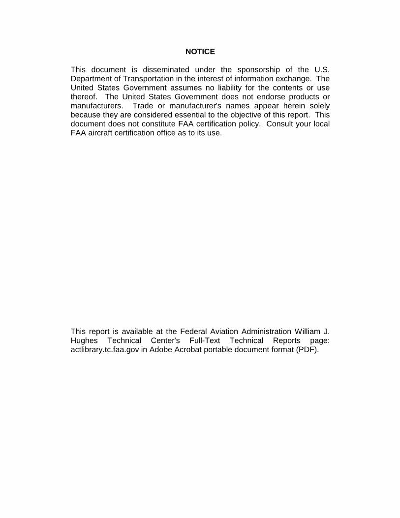
DOT/FAA/AR-00/46 Office of Aviation Research Washington, D.C. 20591
Repair of Composite Laminates December 2000 Final Report This document is available to the U.S. public through the National Technical Information Service (NTIS), Springfield, Virginia 22161.
U.S. Department of Transportation Federal Aviation Administration
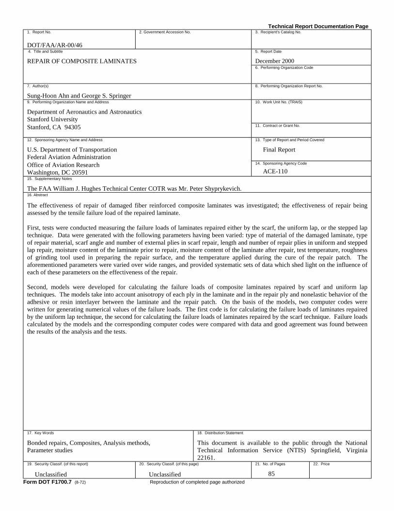
NOTICE
This document is disseminated under the sponsorship of the U.S. Department of Transportation in the interest of information exchange. The United States Government assumes no liability for the contents or use thereof. The United States Government does not endorse products or manufacturers. Trade or manufacturer's names appear herein solely because they are considered essential to the objective of this report. This document does not constitute FAA certification policy. Consult your local FAA aircraft certification office as to its use. This report is available at the Federal Aviation Administration William J. Hughes Technical Center's Full-Text Technical Reports page: actlibrary.tc.faa.gov in Adobe Acrobat portable document format (PDF).
Technical Report Documentation Page 1. Report No. DOT/FAA/AR-00/46
2. Government Accession No. 3. Recipient's Catalog No.
4. Title and Subtitle
REPAIR OF COMPOSITE LAMINATES 5. Report Date
December 2000 6. Performing Organization Code
7. Author(s)
Sung-Hoon Ahn and George S. Springer 8. Performing Organization Report No.
9. Performing Organization Name and Address
Department of Aeronautics and Astronautics Stanford University
10. Work Unit No. (TRAIS)
Stanford, CA 94305 11. Contract or Grant No.
12. Sponsoring Agency Name and Address
U.S. Department of Transportation Federal Aviation Administration
13. Type of Report and Period Covered
Final Report
Office of Aviation Research Washington, DC 20591
14. Sponsoring Agency Code
ACE-110 15. Supplementary Notes
The FAA William J. Hughes Technical Center COTR was Mr. Peter Shyprykevich. 16. Abstract
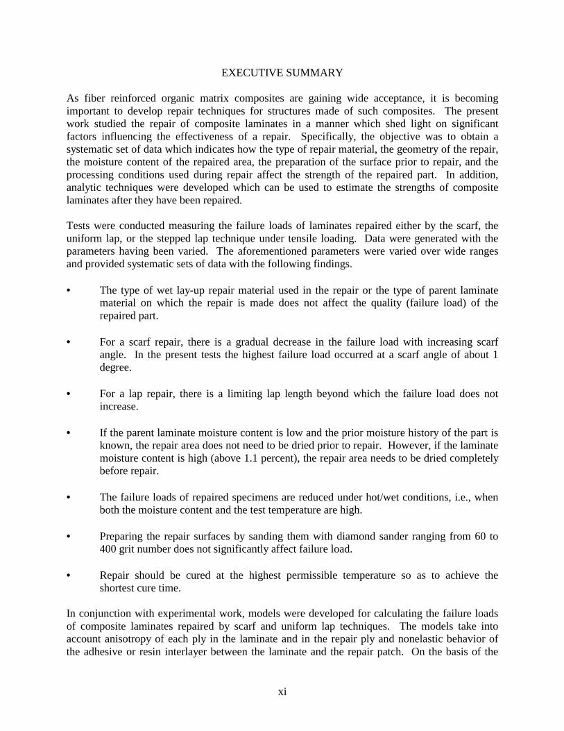
The effectiveness of repair of damaged fiber reinforced composite laminates was investigated; the effectiveness of repair being assessed by the tensile failure load of the repaired laminate. First, tests were conducted measuring the failure loads of laminates repaired either by the scarf, the uniform lap, or the stepped lap technique. Data were generated with the following parameters having been varied: type of material of the damaged laminate, type of repair material, scarf angle and number of external plies in scarf repair, length and number of repair plies in uniform and stepped lap repair, moisture content of the laminate prior to repair, moisture content of the laminate after repair, test temperature, roughness of grinding tool used in preparing the repair surface, and the temperature applied during the cure of the repair patch. The aforementioned parameters were varied over wide ranges, and provided systematic sets of data which shed light on the influence of each of these parameters on the effectiveness of the repair. Second, models were developed for calculating the failure loads of composite laminates repaired by scarf and uniform lap techniques. The models take into account anisotropy of each ply in the laminate and in the repair ply and nonelastic behavior of the adhesive or resin interlayer between the laminate and the repair patch. On the basis of the models, two computer codes were written for generating numerical values of the failure loads. The first code is for calculating the failure loads of laminates repaired by the uniform lap technique, the second for calculating the failure loads of laminates repaired by the scarf technique. Failure loads calculated by the models and the corresponding computer codes were compared with data and good agreement was found between the results of the analysis and the tests. 17. Key Words
Bonded repairs, Composites, Analysis methods, Parameter studies
18. Distribution Statement
This document is available to the public through the National Technical Information Service (NTIS) Springfield, Virginia 22161.
19. Security Classif. (of this report)
Unclassified
20. Security Classif. (of this page)
Unclassified
21. No. of Pages
85
22. Price
Form DOT F1700.7 (8-72) Reproduction of completed page authorized
v
LIST OF FIGURES Figure Page 1 Illustrations of the Scarf and Lap Repair Techniques 1
2 The Base Laminates Prior to Repair 2
3 Illustration of the Repair Techniques Used in This Study 2
4 The Temperature Cycle Used for Curing the Base Laminate and in Making the Repair 4
5 Geometries of the Test Specimens 5
6 Application of the Adhesive Layer When Repairing With Prepreg 5
7 Test Specimens Cut Out of the Repaired Base Laminate 6
8 Specimen Conditions and Test Temperatures 6
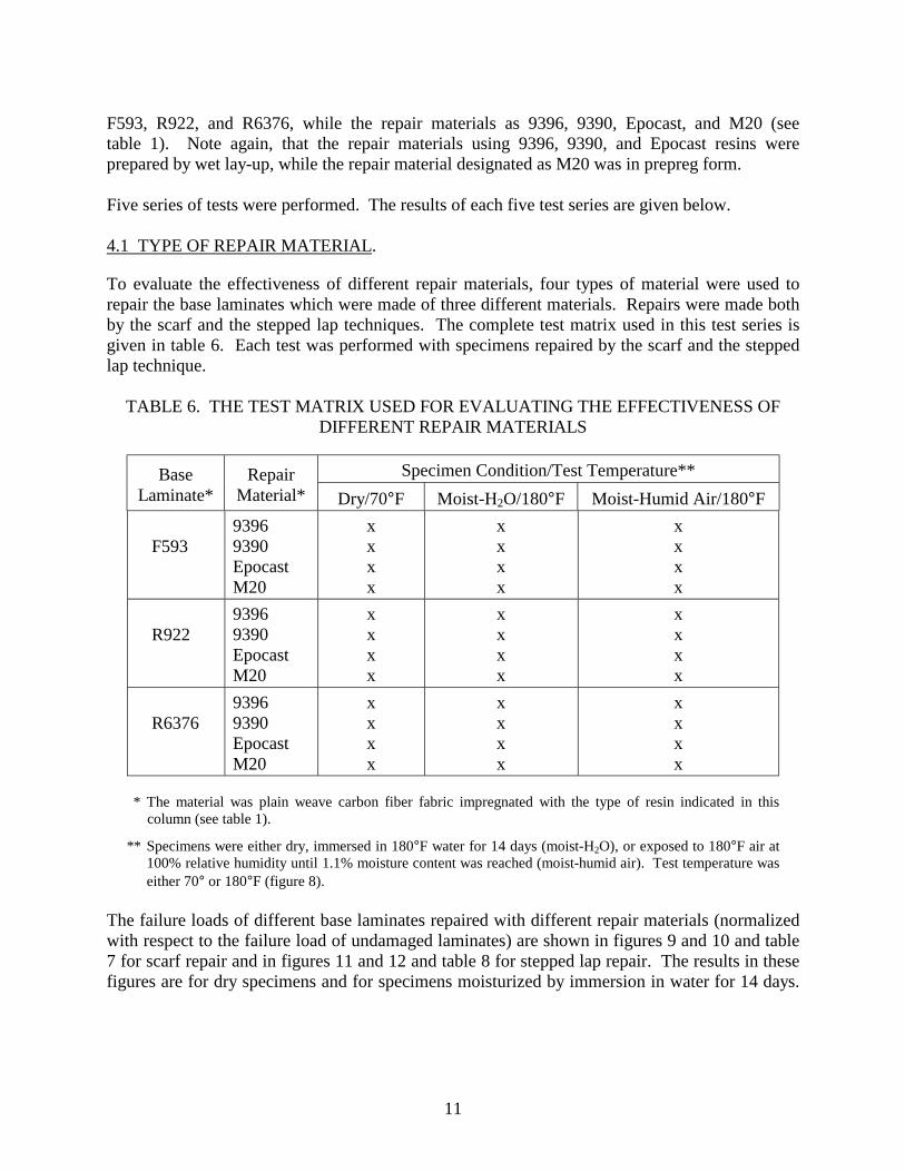
9 Failure Loads of Different Base Laminates Repaired With Different Repair Materials (Scarf Repair at 70°F) 12
10 Failure Loads of Different Base Laminates Repaired With Different Repair Materials (Scarf Repair at 180°F) 12
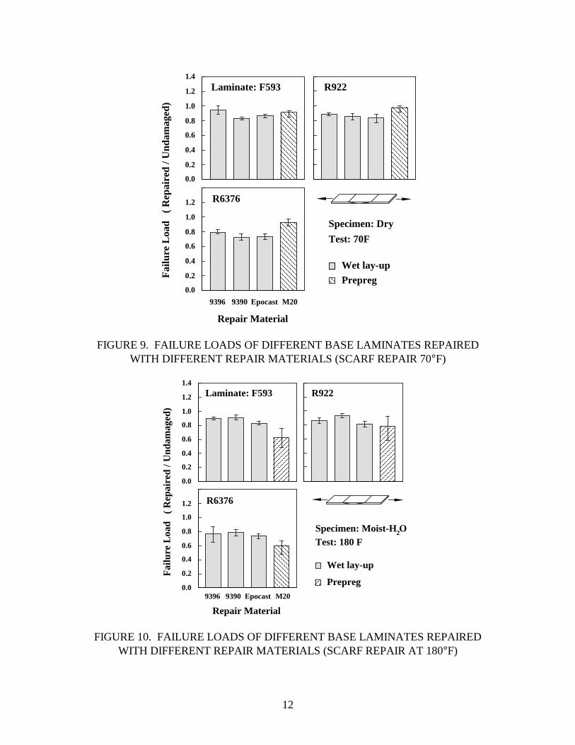
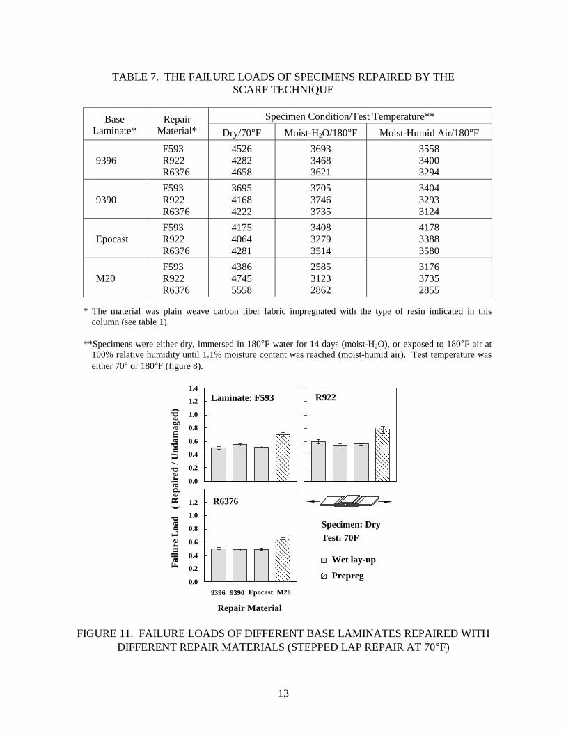
11 Failure Loads of Different Base Laminates Repaired With Different Repair Materials (Stepped Lap Repair at 70°F) 13
12 Failure Loads of Different Base Laminates Repaired With Different Repair Materials (Stepped Lap Repair at 180°F) 14
13 Typical Failure Modes of Specimens Repaired by Scarf and Stepped Lap Techniques 16
14 Definition of the Geometric Factors Investigated 17
15 The Variation of Failure Load With Scarf Angle 19
16 The Effect of the Number of External Plies on the Failure Load in Scarf Repair 19
17 The Effect of Lap Length on the Failure Load in Stepped Lap Repair 20
18 The Effect of Lap Length on the Failure Load in Uniform Lap Repair 20
19 Typical Failure Modes of Specimens Repaired by Stepped Lap and Uniform Lap Techniques With Various Lap Lengths 21
vi
20 The Effect of the Number of Repair Plies on the Failure Load 21
21 Comparisons of the Failure Loads of Specimens Repaired by the Stepped Lap and Uniform Lap Repair Techniques 22
22 Failure Loads of Repaired Specimens When the Base Laminates Were Moisturized Prior to Repair 24
23 The Effects of Specimen Moisture Content and Test Temperature on the Failure Load 25
24 The Failure Loads of Specimens Sanded With Different Grit Diamond Sanders 26
25 Illustration of the Test Setup Used in Studying the Effects of Cure Cycle on the Repair 27
26 The Cure Time Required to Reach Full Cure at Different Cure Temperatures 27
27 A Typical Output of the Microdielectrometer 28
28 Failure Loads of Specimens Repaired at Different Cure Temperatures 29
29 Models of the Uniform Lap and the Scarf Repairs 31
30 The Interlayer Between the Laminate and the Repair Patch When the Repair is Performed With Wet Lay-Up (Lower Left) or Prepreg (Lower Right) 31
31 Illustration of the Shear Stress-Shear Strain Relationship of an Elastic-Perfectly Plastic Interlayer 32
32 Double-Sided Uniform Lap Repair Model 32
33 Double-Sided Uniform Lap Repair Treated in the Model 33
34 Illustration of the Types of Failure Which May Occur in a Laminate Repaired by the Double-Sided Uniform Lap Technique 33
35 The On-Axis (x, y) and Off-Axis (1, 2) Coordinate Systems 34
36 Loads on a Section dx in Length of the Laminate Repaired by the Double-Sided Uniform Lap Technique 36
37 Deformations of the Repair Patch, the Interlayer, and the Laminate 37
38 Possible Regions of the Interlayer Under an Applied Load P 38
39 The Boundary Conditions for the In-Plane Loads in the Laminate and in the Repair Patch and the Continuity Conditions for the Shear Strain in the Interlayer 40
vii
40 The Equations and Boundary Conditions for Calculating the Shear Strain in the Interlayer When the Entire Interlayer Behaves in a Linearly Elastic Manner 41
41 The Equations and Boundary and Continuity Conditions for Calculating the Shear Strain in the Interlayer When the Interlayer is Perfectly Plastic Near the x = 0 End 41
42 The Equations and Boundary and Continuity Conditions for Calculating the Shear Strain in the Interlayer When the Interlayer is Perfectly Plastic Near the x = dl End 42
43 The Equations and Boundary and Continuity Conditions for Calculating the Shear Strain in the Interlayer When the Interlayer is Perfectly Plastic Near the x = 0 and x = dl Ends 42
44 Scarf Repairs Treated in the Model 44
45 The Types of Failure Which May Occur in a Laminate Repaired by the Scarf Technique 44
46 The Scarf Repair Treated in the Model 45
47 Loads on a Section dx in Length of the k-th Segment of the Laminate Repaired by the Scarf Technique 46
48 Deformations of the Repair Patch, the Interlayer, and the Laminate in the k-th Segment of a Laminate Repaired by the Scarf Technique 47
49 The Compliance Matrices in the Laminate and the Repair Patch 48
50 Possible Regions of the Interlayer Under an Applied Load P 48
51 Model of the Boundary at the Outer Edge (x = xK) of the Repair Patch 51
52 The Boundary Conditions for the In-Plane Loads in the Laminate and in the Repair Patch 51
53 The Continuity Conditions at the Edge of the k-th Segment 52
54 The Continuity Conditions at the Interlayer Between the Elastic and Perfectly Plastic Regions 52
55 The Equations and Boundary Conditions for Calculating the Shear Strain in the Interlayer When the Entire Interlayer Behaves in a Linearly Elastic Manner 53
56 The Equations and Boundary and Continuity Conditions for Calculating the Shear Strain in the Interlayer When the Interlayer is Perfectly Plastic Near the x = 0 End 53
57 The Equations and Boundary and Continuity Conditions for Calculating the Shear Strain in the Interlayer When the Interlayer is Perfectly Plastic Near the x = xK End 54
viii
58 The Equations and Boundary and Continuity Conditions for Calculating the Shear Strain in the Interlayer When the Interlayer is Perfectly Plastic Near the x = 0 and x = xK Ends 54
59 Comparisons of the Calculated (Model) and the Measured (Data) Failure Loads as a Function of Lap Length for 8-Ply Laminate 60
60 Comparison of the Calculated (Model) and the Measured (Data) Failure Loads as a Function of Lap Length for 32-Ply Laminate 61
61 Comparisons of the Calculated (Model) and the Measured (Data) Failure Loads as a Function of Scarf Angle 61
62 Comparison of the Calculated (Model) and the Measured (Data) Failure Loads as a Function of Extra Plies 62
LIST OF TABLES Table Page 1 The Base Materials, Repair Materials, and Cure Cycles Used for Fabricating the Base
Laminate and for Making the Repair 3
2 Average Tensile Properties of Specimens Made of Materials Used for Fabricating the Base Laminates 7
3 Average Tensile Properties of Specimens Made of Materials Used for Repair 8
4 Normalized (63% Fiber Volume) Tensile Properties of Specimens Made of Materials Used for Fabricating the Base Laminates 9
5 Normalized (63% Fiber Volume) Tensile Properties of Specimens Made of Materials Used for Repair 10
6 The Test Matrix Used for Evaluating the Effectiveness of Different Repair Materials 11
7 The Failure Loads of Specimens Repaired by the Scarf Technique 13
8 The Failure Loads of Specimens Repaired by the Stepped Lap Technique 14
9 Test Matrix Used for Evaluating the Effects of Different Geometries of the Scarf and Lap Repairs 17
10 The Test Matrix Used for Evaluating the Effects of the Moisture Content of the Base Laminate Prior to Repair 23
ix/x
11 The Test Matrix Used for Evaluating the Effects of Specimen Moisture Content and Test Temperature 24
12 Tests With Different Preparation of the Repair Surface 26
13 The Input Parameters Required by RepairL and the Numerical Values Used in the Present Calculations for 3k70 Plain Weave Fabric Impregnated With 9396 Resin 58
14 The Input Parameters Required by RepairS and the Numerical Values Used in the Present Calculations for 3k70 Plain Weave Fabric Impregnated With 9396 Resin 59

xii
models, two computer codes were written for generating numerical values of the failure loads. The first code is for calculating the failure loads of laminates repaired by the uniform lap technique, the second for calculating the failure loads of laminates repaired by the scarf technique. Failure loads calculated by the models and the corresponding computer codes were compared with data and good agreement was found between the results of the analysis and the tests.

2
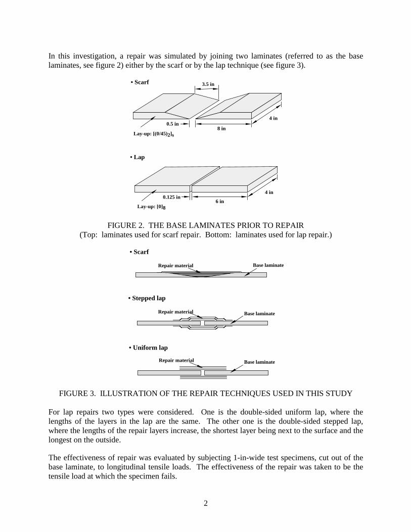
In this investigation, a repair was simulated by joining two laminates (referred to as the base laminates, see figure 2) either by the scarf or by the lap technique (see figure 3).
• Scarf
• Lap
4 in
8 in
6 in
4 in
0.5 in
0.125 in
3.5 in
Lay-up: [(0/45)2]s
Lay-up: [0]8
FIGURE 2. THE BASE LAMINATES PRIOR TO REPAIR (Top: laminates used for scarf repair. Bottom: laminates used for lap repair.)
Repair material Base laminate
• Scarf
Repair material Base laminate
• Uniform lap
Repair material Base laminate
• Stepped lap
FIGURE 3. ILLUSTRATION OF THE REPAIR TECHNIQUES USED IN THIS STUDY For lap repairs two types were considered. One is the double-sided uniform lap, where the lengths of the layers in the lap are the same. The other one is the double-sided stepped lap, where the lengths of the repair layers increase, the shortest layer being next to the surface and the longest on the outside. The effectiveness of repair was evaluated by subjecting 1-in-wide test specimens, cut out of the base laminate, to longitudinal tensile loads. The effectiveness of the repair was taken to be the tensile load at which the specimen fails.
4
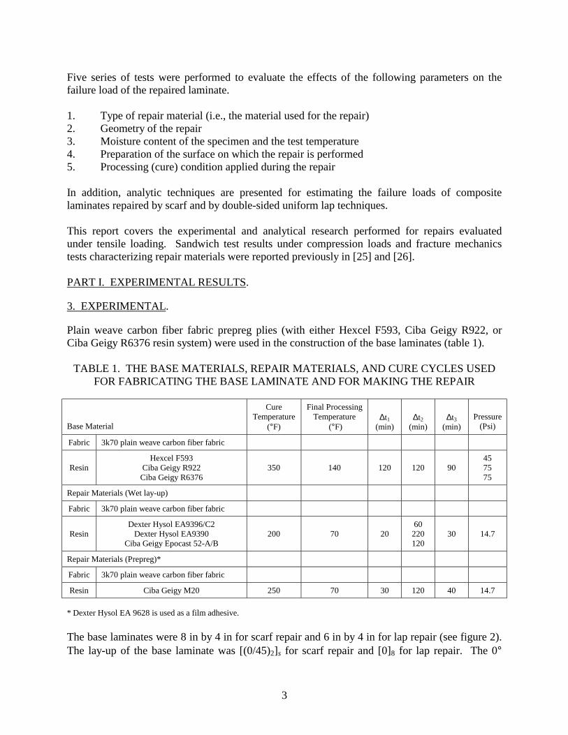
refers to fabric which has fibers parallel and perpendicular to the longitudinal axis. The 45° designates plies in which the fibers are ±45° from the longitudinal axis. Each base laminate was laid up by hand, vacuum bagged, and cured in an autoclave by the manufacturer’s cure cycle (figure 4 and table 1). Same cure cycle was used for the scarf and patch repairs, figure 4. The thicknesses of the cured base laminates ranged from 0.057 to 0.070 in. The autoclave pressure (during fabrication of base laminates) or the vacuum (during repair) were applied at time t = 0 and were kept constant during the cure.
Temp. (F)
Time (min)
70 F
∆t1 ∆t2 ∆t3
Max. cure temp.
Finalprocessingtemp.
FIGURE 4. THE TEMPERATURE CYCLE USED FOR CURING THE BASE LAMINATE AND IN MAKING THE REPAIR
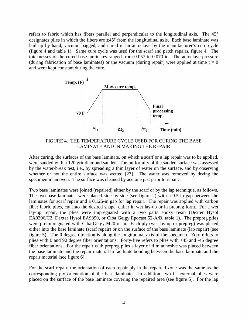
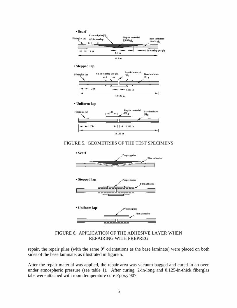
After curing, the surfaces of the base laminate, on which a scarf or a lap repair was to be applied, were sanded with a 120 grit diamond sander. The uniformity of the sanded surface was assessed by the water-break test, i.e., by spreading a thin layer of water on the surface, and by observing whether or not the entire surface was wetted [27]. The water was removed by drying the specimen in an oven. The surface was cleaned by acetone just prior to repair. Two base laminates were joined (repaired) either by the scarf or by the lap technique, as follows. The two base laminates were placed side by side (see figure 2) with a 0.5-in gap between the laminates for scarf repair and a 0.125-in gap for lap repair. The repair was applied with carbon fiber fabric plies, cut into the desired shape, either in wet lay-up or in prepreg form. For a wet lay-up repair, the plies were impregnated with a two parts epoxy resin (Dexter Hysol EA9396/C2, Dexter Hysol EA9390, or Ciba Geigy Epocast 52-A/B, table 1). The prepreg plies were preimpregnated with Ciba Geigy M20 resin. Each ply (wet lay-up or prepreg) was placed either into the base laminate (scarf repair) or on the surface of the base laminate (lap repair) (see figure 5). The 0 degree direction is along the longitudinal axis of the specimen. Zero refers to plies with 0 and 90 degree fiber orientations. Forty-five refers to plies with +45 and -45 degree fiber orientations. For the repair with prepreg plies a layer of film adhesive was placed between the base laminate and the repair material to facilitate bonding between the base laminate and the repair material (see figure 6). For the scarf repair, the orientation of each repair ply in the repaired zone was the same as the corresponding ply orientation of the base laminate. In addition, two 0° external plies were placed on the surface of the base laminate covering the repaired area (see figure 5). For the lap
5
12.125 in
Repair material
2 in
Fiberglas tab Base laminate[0] 8
[0]
0.125 in
• Uniform lap
31 in
2 Repair material Base laminate
16.5 in
[(0/45)2]s[(0/45)2]s
External plies[0]
0.5 in
0.5 in overlap
2 in
12.125 in
Repair material
2 in
Base laminate[0] 8
[0]
0.125 in
• Stepped lap
3Fiberglas tab 0.5 in overlap per ply
• Scarf
Fiberglas tab
0.5 in overlap per ply
FIGURE 5. GEOMETRIES OF THE TEST SPECIMENS
Film adhesive
• Uniform lap
Film adhesive
Prepreg plies
• Stepped lapFilm adhesive
Prepreg plies
• ScarfPrepreg plies
FIGURE 6. APPLICATION OF THE ADHESIVE LAYER WHEN REPAIRING WITH PREPREG
repair, the repair plies (with the same 0° orientations as the base laminate) were placed on both sides of the base laminate, as illustrated in figure 5. After the repair material was applied, the repair area was vacuum bagged and cured in an oven under atmospheric pressure (see table 1). After curing, 2-in-long and 0.125-in-thick fiberglas tabs were attached with room temperature cure Epoxy 907.
6
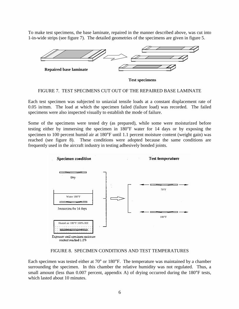
To make test specimens, the base laminate, repaired in the manner described above, was cut into 1-in-wide strips (see figure 7). The detailed geometries of the specimens are given in figure 5.
Repaired base laminate
Test specimens
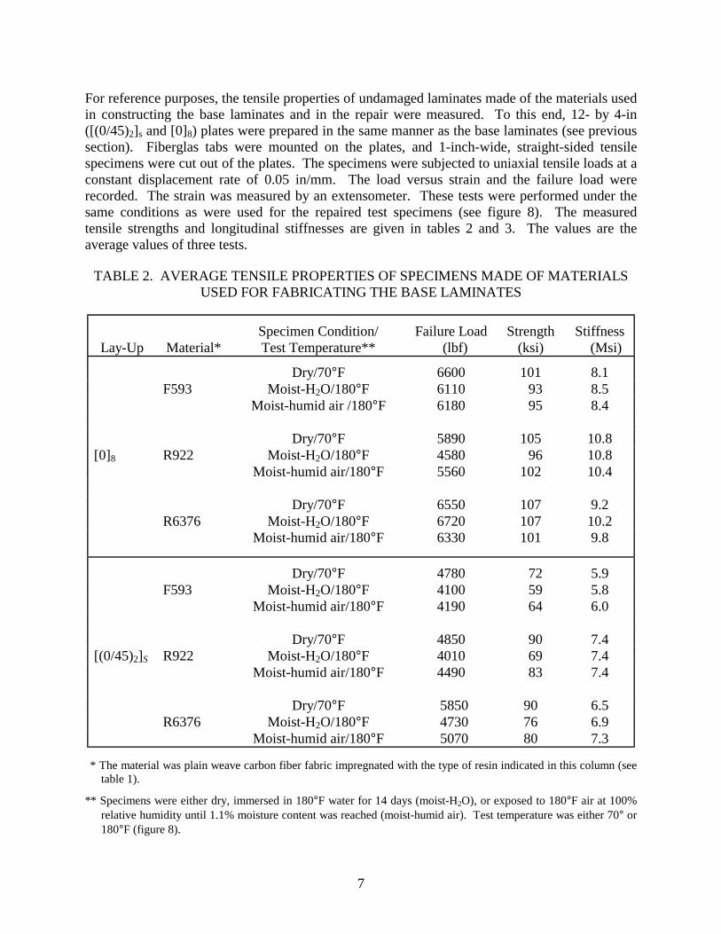
FIGURE 7. TEST SPECIMENS CUT OUT OF THE REPAIRED BASE LAMINATE Each test specimen was subjected to uniaxial tensile loads at a constant displacement rate of 0.05 in/mm. The load at which the specimen failed (failure load) was recorded. The failed specimens were also inspected visually to establish the mode of failure. Some of the specimens were tested dry (as prepared), while some were moisturized before testing either by immersing the specimen in 180°F water for 14 days or by exposing the specimen to 100 percent humid air at 180°F until 1.1 percent moisture content (weight gain) was reached (see figure 8). These conditions were adopted because the same conditions are frequently used in the aircraft industry in testing adhesively bonded joints.
FIGURE 8. SPECIMEN CONDITIONS AND TEST TEMPERATURES Each specimen was tested either at 70° or 180°F. The temperature was maintained by a chamber surrounding the specimen. In this chamber the relative humidity was not regulated. Thus, a small amount (less than 0.007 percent, appendix A) of drying occurred during the 180°F tests, which lasted about 10 minutes.
70°F
180°F
Water 180°F
Humid air 180°F 100% RH
7
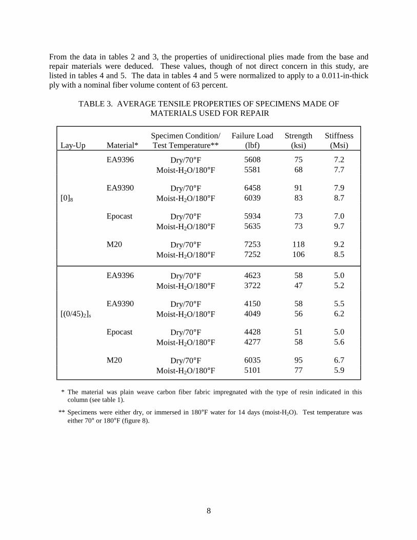
For reference purposes, the tensile properties of undamaged laminates made of the materials used in constructing the base laminates and in the repair were measured. To this end, 12- by 4-in ([(0/45)2]s and [0]8) plates were prepared in the same manner as the base laminates (see previous section). Fiberglas tabs were mounted on the plates, and 1-inch-wide, straight-sided tensile specimens were cut out of the plates. The specimens were subjected to uniaxial tensile loads at a constant displacement rate of 0.05 in/mm. The load versus strain and the failure load were recorded. The strain was measured by an extensometer. These tests were performed under the same conditions as were used for the repaired test specimens (see figure 8). The measured tensile strengths and longitudinal stiffnesses are given in tables 2 and 3. The values are the average values of three tests.
TABLE 2. AVERAGE TENSILE PROPERTIES OF SPECIMENS MADE OF MATERIALS USED FOR FABRICATING THE BASE LAMINATES
Lay-Up
Material*
Specimen Condition/ Test Temperature**
Failure Load (lbf)
Strength (ksi)
Stiffness (Msi)
Dry/70°F 6600 101 8.1 F593 Moist-H2O/180°F 6110 93 8.5 Moist-humid air /180°F 6180 95 8.4 Dry/70°F 5890 105 10.8 [0]8 R922 Moist-H2O/180°F 4580 96 10.8 Moist-humid air/180°F 5560 102 10.4 Dry/70°F 6550 107 9.2 R6376 Moist-H2O/180°F 6720 107 10.2 Moist-humid air/180°F 6330 101 9.8
Dry/70°F 4780 72 5.9 F593 Moist-H2O/180°F 4100 59 5.8 Moist-humid air/180°F 4190 64 6.0 Dry/70°F 4850 90 7.4 [(0/45)2]S R922 Moist-H2O/180°F 4010 69 7.4 Moist-humid air/180°F 4490 83 7.4 Dry/70°F 5850 90 6.5 R6376 Moist-H2O/180°F 4730 76 6.9 Moist-humid air/180°F 5070 80 7.3
* The material was plain weave carbon fiber fabric impregnated with the type of resin indicated in this column (see
table 1).
** Specimens were either dry, immersed in 180°F water for 14 days (moist-H2O), or exposed to 180°F air at 100% relative humidity until 1.1% moisture content was reached (moist-humid air). Test temperature was either 70° or 180°F (figure 8).
8
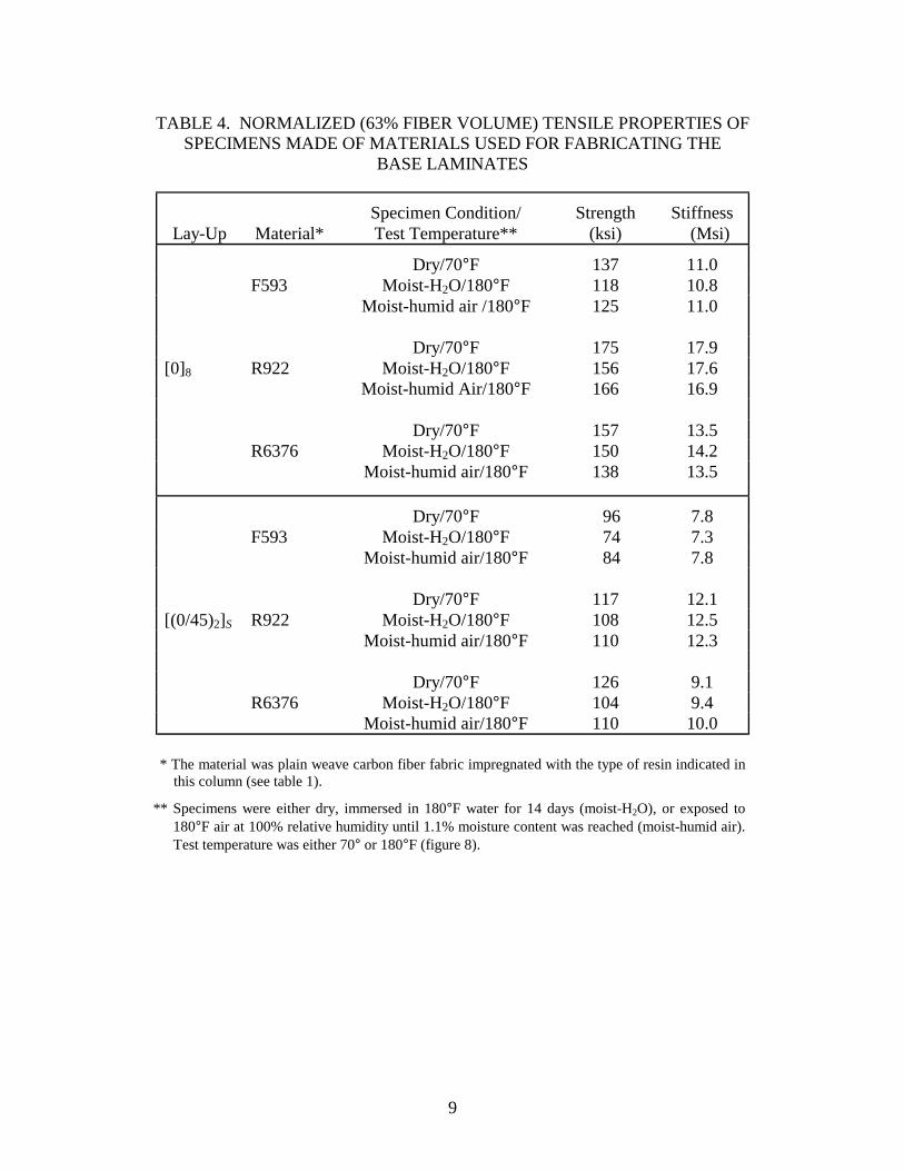
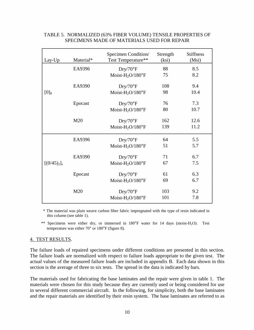
From the data in tables 2 and 3, the properties of unidirectional plies made from the base and repair materials were deduced. These values, though of not direct concern in this study, are listed in tables 4 and 5. The data in tables 4 and 5 were normalized to apply to a 0.011-in-thick ply with a nominal fiber volume content of 63 percent.
TABLE 3. AVERAGE TENSILE PROPERTIES OF SPECIMENS MADE OF MATERIALS USED FOR REPAIR
Lay-Up
Material*
Specimen Condition/ Test Temperature**
Failure Load (lbf)
Strength (ksi)
Stiffness (Msi)
Dry/70°F 5608 75 7.2
EA9396 Moist-H2O/180°F 5581 68 7.7
Dry/70°F 6458 91 7.9 [0]8
EA9390 Moist-H2O/180°F 6039 83 8.7
Dry/70°F 5934 73 7.0
Epocast Moist-H2O/180°F 5635 73 9.7
Dry/70°F 7253 118 9.2
M20 Moist-H2O/180°F 7252 106 8.5
Dry/70°F 4623 58 5.0
EA9396 Moist-H2O/180°F 3722 47 5.2
Dry/70°F 4150 58 5.5 [(0/45)2]s
EA9390 Moist-H2O/180°F 4049 56 6.2
Dry/70°F 4428 51 5.0
Epocast Moist-H2O/180°F 4277 58 5.6
Dry/70°F 6035 95 6.7
M20 Moist-H2O/180°F 5101 77 5.9
* The material was plain weave carbon fiber fabric impregnated with the type of resin indicated in this
column (see table 1).
** Specimens were either dry, or immersed in 180°F water for 14 days (moist-H2O). Test temperature was either 70° or 180°F (figure 8).
9
TABLE 4. NORMALIZED (63% FIBER VOLUME) TENSILE PROPERTIES OF SPECIMENS MADE OF MATERIALS USED FOR FABRICATING THE
BASE LAMINATES
Lay-Up
Material*
Specimen Condition/ Test Temperature**
Strength (ksi)
Stiffness (Msi)
Dry/70°F 137 11.0 F593 Moist-H2O/180°F 118 10.8 Moist-humid air /180°F 125 11.0 Dry/70°F 175 17.9 [0]8 R922 Moist-H2O/180°F 156 17.6 Moist-humid Air/180°F 166 16.9 Dry/70°F 157 13.5 R6376 Moist-H2O/180°F 150 14.2 Moist-humid air/180°F 138 13.5
Dry/70°F 96 7.8 F593 Moist-H2O/180°F 74 7.3 Moist-humid air/180°F 84 7.8 Dry/70°F 117 12.1 [(0/45)2]S R922 Moist-H2O/180°F 108 12.5 Moist-humid air/180°F 110 12.3 Dry/70°F 126 9.1 R6376 Moist-H2O/180°F 104 9.4 Moist-humid air/180°F 110 10.0
* The material was plain weave carbon fiber fabric impregnated with the type of resin indicated in
this column (see table 1).
** Specimens were either dry, immersed in 180°F water for 14 days (moist-H2O), or exposed to 180°F air at 100% relative humidity until 1.1% moisture content was reached (moist-humid air). Test temperature was either 70° or 180°F (figure 8).
12
0.0
0.2
0.4
0.6
0.8
1.0
1.2
1.4
0.0
0.2
0.4
0.6
0.8
1.0
1.2
1.4
Prepreg
Wet lay-up
Fai
lure
Loa
d (
Rep
aire
d / U
ndam
aged
)
R6376
Laminate: F593 R922
Specimen: Dry
Test: 70F
9396 9390 Epocast M20
Repair Material
FIGURE 9. FAILURE LOADS OF DIFFERENT BASE LAMINATES REPAIRED WITH DIFFERENT REPAIR MATERIALS (SCARF REPAIR 70°F)
0.0
0.2
0.4
0.6
0.8
1.0
1.2
1.4
Fai
lure
Loa
d (
Rep
aire
d / U
ndam
aged
)
Prepreg
Wet lay-up
0.0
0.2
0.4
0.6
0.8
1.0
1.2
1.4Laminate: F593 R922
R6376
9396 9390 Epocast M20
Repair Material
2Specimen: Moist-H OTest: 180 F
FIGURE 10. FAILURE LOADS OF DIFFERENT BASE LAMINATES REPAIRED WITH DIFFERENT REPAIR MATERIALS (SCARF REPAIR AT 180°F)
13
TABLE 7. THE FAILURE LOADS OF SPECIMENS REPAIRED BY THE SCARF TECHNIQUE
Specimen Condition/Test Temperature** Base Laminate*
Repair Material* Dry/70°F Moist-H2O/180°F Moist-Humid Air/180°F
9396
F593 R922 R6376
4526 4282 4658
3693 3468 3621
3558 3400 3294
9390
F593 R922 R6376
3695 4168 4222
3705 3746 3735
3404 3293 3124
Epocast
F593 R922 R6376
4175 4064 4281
3408 3279 3514
4178 3388 3580
M20
F593 R922 R6376
4386 4745 5558
2585 3123 2862
3176 3735 2855
* The material was plain weave carbon fiber fabric impregnated with the type of resin indicated in this
column (see table 1). **Specimens were either dry, immersed in 180°F water for 14 days (moist-H2O), or exposed to 180°F air at
100% relative humidity until 1.1% moisture content was reached (moist-humid air). Test temperature was either 70° or 180°F (figure 8).
0.0
0.2
0.4
0.6
0.8
1.0
1.2
1.4
0.0
0.2
0.4
0.6
0.8
1.0
1.2
1.4
Fai
lure
Loa
d (
Rep
aire
d / U
ndam
aged
)
Prepreg
Wet lay-up
Laminate: F593 R922
R6376
9396 9390 Epocast M20
Repair Material
Specimen: Dry
Test: 70F
FIGURE 11. FAILURE LOADS OF DIFFERENT BASE LAMINATES REPAIRED WITH DIFFERENT REPAIR MATERIALS (STEPPED LAP REPAIR AT 70°F)

14
0.0
0.2
0.4
0.6
0.8
1.0
1.2
1.4
0.0
0.2
0.4
0.6
0.8
1.0
1.2
1.4F
ailu
re L
oad
( R
epai
red
/ Und
amag
ed)
Prepreg
Wet lay-up
Laminate: F593 R922
R6376
9396 9390 Epocast M20
Repair Material
2Specimen: Moist-H O
Test: 180 F
FIGURE 12. FAILURE LOADS OF DIFFERENT BASE LAMINATES REPAIRED WITH DIFFERENT REPAIR MATERIALS (STEPPED LAP REPAIR AT 180°F)
TABLE 8. THE FAILURE LOADS OF SPECIMENS REPAIRED BY THE
STEPPED LAP TECHNIQUE
Specimen Condition/Test Temperature** Base Laminate*
Repair Material* Dry/70°F Moist-H2O/180°F Moist-Humid Air/180°F
9396
F593 R922 R6376
3360 3547 3302
2958 2533 2520
2624 2311 2096
9390
F593 R922 R6376
3638 3238 3195
2945 2612 2497
2351 2821 2003
Epocast
F593 R922 R6376
3420 3298 3223
2674 2642 2307
2570 2777 2284
M20
F593 R922 R6376
4516 4646 4249
2148 2097 2033
3150 3995 3189
* The material was plain weave carbon fiber fabric impregnated with the type of resin indicated in this
column (see table 1).
** Specimens were either dry, or immersed in 180°F water for 14 days (moist-H2O), or exposed to 180°F air at 100% relative humidity until 1.1% moisture content was reached (moist-humid air). Test temperature was either 70° or 180°F (figure 8).
15
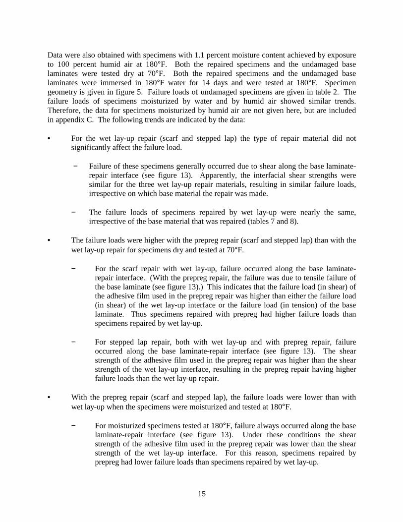
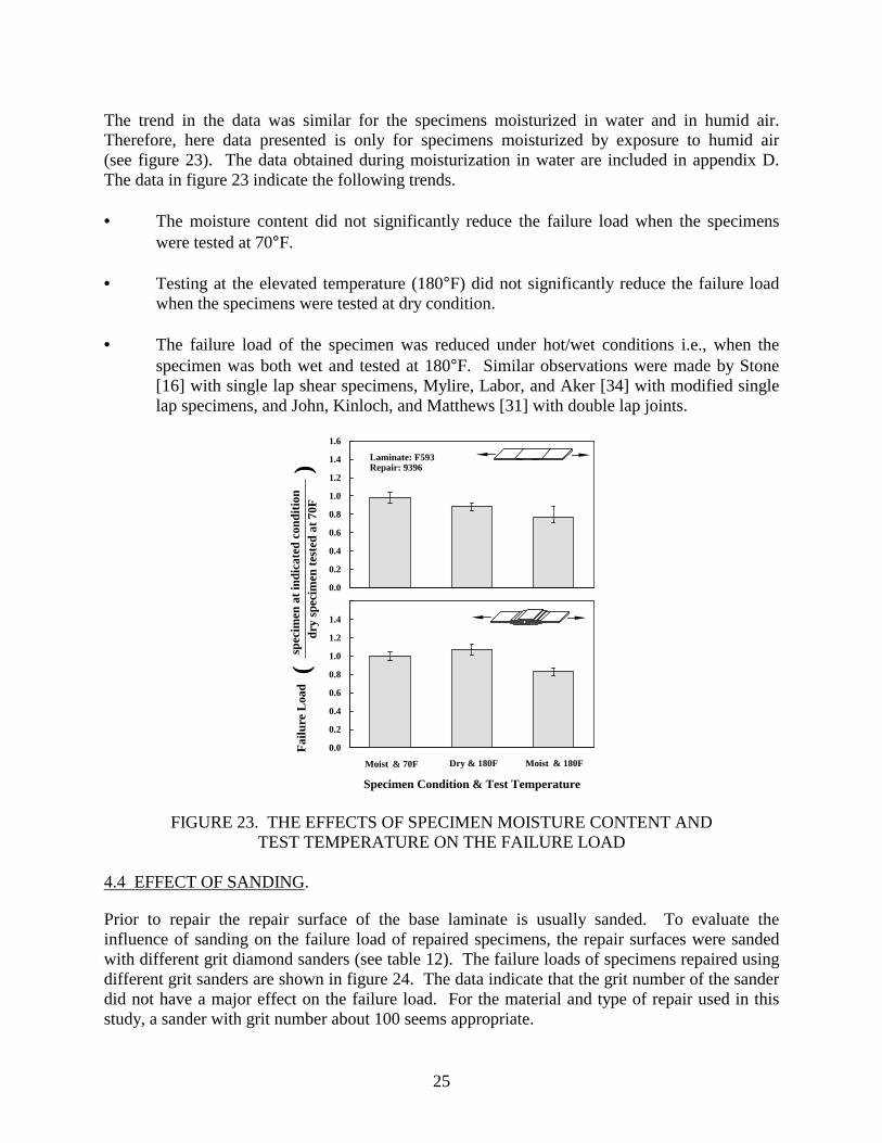
Data were also obtained with specimens with 1.1 percent moisture content achieved by exposure to 100 percent humid air at 180°F. Both the repaired specimens and the undamaged base laminates were tested dry at 70°F. Both the repaired specimens and the undamaged base laminates were immersed in 180°F water for 14 days and were tested at 180°F. Specimen geometry is given in figure 5. Failure loads of undamaged specimens are given in table 2. The failure loads of specimens moisturized by water and by humid air showed similar trends. Therefore, the data for specimens moisturized by humid air are not given here, but are included in appendix C. The following trends are indicated by the data: • For the wet lay-up repair (scarf and stepped lap) the type of repair material did not
significantly affect the failure load.
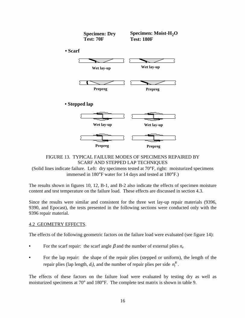
− Failure of these specimens generally occurred due to shear along the base laminate-repair interface (see figure 13). Apparently, the interfacial shear strengths were similar for the three wet lay-up repair materials, resulting in similar failure loads, irrespective on which base material the repair was made.
− The failure loads of specimens repaired by wet lay-up were nearly the same,
irrespective of the base material that was repaired (tables 7 and 8). • The failure loads were higher with the prepreg repair (scarf and stepped lap) than with the
wet lay-up repair for specimens dry and tested at 70°F.
− For the scarf repair with wet lay-up, failure occurred along the base laminate-repair interface. (With the prepreg repair, the failure was due to tensile failure of the base laminate (see figure 13).) This indicates that the failure load (in shear) of the adhesive film used in the prepreg repair was higher than either the failure load (in shear) of the wet lay-up interface or the failure load (in tension) of the base laminate. Thus specimens repaired with prepreg had higher failure loads than specimens repaired by wet lay-up.
− For stepped lap repair, both with wet lay-up and with prepreg repair, failure
occurred along the base laminate-repair interface (see figure 13). The shear strength of the adhesive film used in the prepreg repair was higher than the shear strength of the wet lay-up interface, resulting in the prepreg repair having higher failure loads than the wet lay-up repair.
• With the prepreg repair (scarf and stepped lap), the failure loads were lower than with
wet lay-up when the specimens were moisturized and tested at 180°F.
− For moisturized specimens tested at 180°F, failure always occurred along the base laminate-repair interface (see figure 13). Under these conditions the shear strength of the adhesive film used in the prepreg repair was lower than the shear strength of the wet lay-up interface. For this reason, specimens repaired by prepreg had lower failure loads than specimens repaired by wet lay-up.
17
• Uniform lap
Lap length, dl
Repair plies
External plies
• Stepped lapdl
Repair plies
Lap length, dl
(Number per side: nR
• Scarf
tan(β)= dsHH
ds
nR ll)
(Number per side: nRl )
Base laminate(Number per side: nL
l )
(Number: ne )
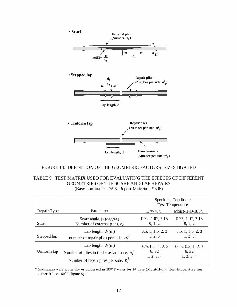
FIGURE 14. DEFINITION OF THE GEOMETRIC FACTORS INVESTIGATED
TABLE 9. TEST MATRIX USED FOR EVALUATING THE EFFECTS OF DIFFERENT GEOMETRIES OF THE SCARF AND LAP REPAIRS
(Base Laminate: F593, Repair Material: 9396)
Specimen Condition/ Test Temperature
Repair Type Parameter Dry/70°F Moist-H2O/180°F
Scarf
Scarf angle, β (degree) Number of external plies, ne
0.72, 1.07, 2.15 0, 1, 2
0.72, 1.07, 2.15 0, 1, 2
Stepped lap
Lap length, dl (in) number of repair plies per side, R
ln 0.5, 1, 1.5, 2, 3
1, 2, 3 0.5, 1, 1.5, 2, 3
1, 2, 3
Uniform lap
Lap length, dl (in)
Number of plies in the base laminate, Lln
Number of repair plies per side, Rln
0.25, 0.5, 1, 2, 3 8, 32
1, 2, 3, 4
0.25, 0.5, 1, 2, 3 8, 32
1, 2, 3, 4
* Specimens were either dry or immersed in 180°F water for 14 days (Moist-H2O). Test temperature was either 70° or 180°F (figure 8).

18
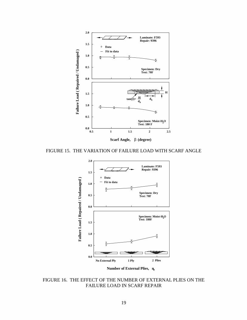
The results are presented in figures 15 and 16 for the scarf repair and in figures 17 to 21 for the lap repair. The following general observations can be made on the basis of the data given in these figures. • For the scarf repair
− The failure load decreased with increasing scarf angle (see figure 15). Similar observations were made by Kim, Lee, and Lee [28].
− The addition of external plies on the surface of the specimen resulted in an
increased failure loads (see figure 16). These results are in agreement with those found by Myhre and Beck [29].
• For the lap repair
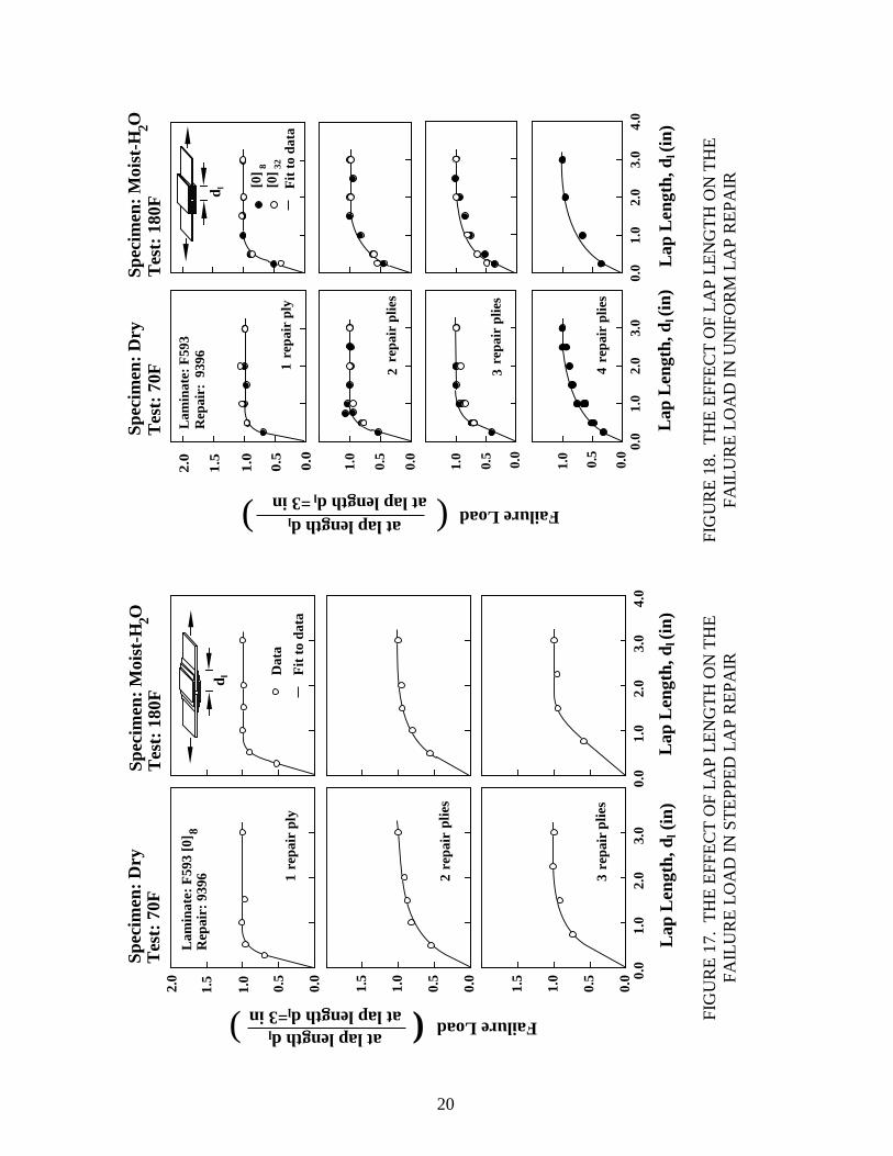
− The failure load increased with increasing lap length but only up to a certain “limiting lap length” dlimit (see figures 17 to 18). This limiting lap length was generally between 2 and 3 inches for the specimens used in this investigation. Beyond the limiting lap length an increase in lap length did not affect the failure load. Thus, there is no benefit to be gained by making the lap length longer than the limiting lap length. Similar results were reported by Chan and Sun [30], and John, Kinloch, and Matthews [31].
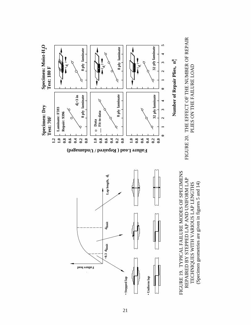
− The mode of failure changed with lap length (see figure 19). At short (dl ≤
0.3dlimit) and intermediate lap length (0.3dlimit ≤ d1 ≤ dlimit), failure occurred mostly along the interface, with some of the repair plies also failing by tension at the intermediate lap length. At and beyond the limiting lap length (dl, ≥ dlimit) failure was due to tensile failure of the repair plies. These conclusions seemed to hold even when the total number of repair plies (2 R
ln ) was the same as the number of
plies in the base laminate ( Lln ). (Note, that for the specimens in section 4.1, the
lap length was 1.5 in, and this corresponds to an intermediate lap length.)
− The failure load increased linearly with the number of plies used in the repair (see figure 20). This result was valid even when the total number of repair plies (2 L
ln )
was equal to the number of plies in the base laminate ( Rln ) (see figure 20 middle).
− When the lap length was greater than limiting lap length (dl ≥ dlimit), the shape of
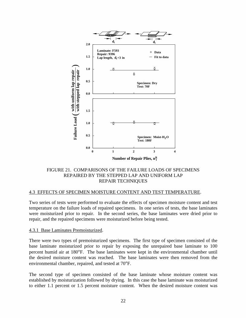
the repair plies did not markedly affect the failure load (see figure 21). The failure loads were nearly the same for specimens repaired by stepped and by uniform repair, provided the following two conditions were simultaneously satisfied: (a) the number of repair plies were the same and (b) the lap length of the uniform lap repair was the same as the length of the outside lap of the stepped repair.
19
Fai
lure
Loa
d (
Rep
aire
d / U
ndam
aged
)
Laminate: F593Repair: 9396
Specimen: Moist-H OTest: 180 F
Specimen: DryTest: 70F
Scarf Angle, β (degree)
2
Data
Fit to data
tan(β)= Hds
ds
H
0.0
0.5
1.0
1.5
2.0
0.0
0.5
1.0
1.5
0.5 1 1.5 2 2.5
FIGURE 15. THE VARIATION OF FAILURE LOAD WITH SCARF ANGLE
Fai
lure
Loa
d (
Rep
aire
d / U
ndam
aged
)
Specimen: DryTest: 70F
Laminate: F593Repair: 9396
Number of External Plies, ne
Specimen: Moist-H OTest: 180F
2
Data
Fit to data
No External Ply 1 Ply 2 Plies
0.0
0.5
1.0
1.5
2.0
0.5
1.0
1.5
0.0
FIGURE 16. THE EFFECT OF THE NUMBER OF EXTERNAL PLIES ON THE FAILURE LOAD IN SCARF REPAIR
20
0.0
1.0
2.0
3.0
4.0
Lap
Len
gth,
dl (
in)
0.0
0.5
1.0
1.5
2.0
0.0
0.5
1.0
1.5
Failure Load
0.0
0.5
1.0
1.5 0.
01.
02.
03.
0
Lap
Len
gth,
dl (
in)
Spec
imen
: D
ryT
est:
70F
Spec
imen
: M
oist
-H O
Tes
t: 1
80F
2
Lam
inat
e: F
593
[0]
Rep
air:
939
68
at lap length dl
at lap length dl=3 in)
1 re
pair
ply
2 re
pair
plie
s
3 re
pair
plie
s
Fit
to
data
Dat
a
d l
(
Fit
to
data
[0]8 32
[0]
d l
0.0
0.5
1.0
1.5
2.0
0.0
0.5
1.0
Spec
imen
: M
oist
-H O
Tes
t: 1
80F
2
0.0
0.5
1.0
Failure Load
Lam
inat
e: F
593
Rep
air:
939
6
Spec
imen
: D
ryT
est:
70F
1 r
epai
r pl
y
at lap length dl
at lap length dl =3 in)
2 r
epai
r pl
ies
3 r
epai
r pl
ies
0.0
1.0
2.0
3.0
4.0
Lap
Len
gth,
dl (
in)
4 r
epai
r pl
ies
(0.
0
0.5
1.0
0.0
1.0
2.0
3.0
Lap
Len
gth,
dl (
in)
FIG
UR
E 17
. TH
E EF
FEC
T O
F LA
P LE
NG
TH O
N T
HE
FAIL
UR
E LO
AD
IN S
TEPP
ED L
AP
REP
AIR
FI
GU
RE
18.
THE
EFFE
CT
OF
LAP
LEN
GTH
ON
TH
E FA
ILU
RE
LOA
D IN
UN
IFO
RM
LA
P R
EPA
IR
21
• St
eppe
d la
p
• U
nifo
rm la
p
Failure load
~0.3
dlim
itd l
imit
Lap
leng
th,
d l
Num
ber
of R
epai
r P
lies,
n
Spec
imen
: M
oist
-H O
Tes
t: 1
80 F
2Sp
ecim
en:
Dry
Tes
t: 7
0F
R lFailure Load ( Repaired / Undamaged)
12
34
01
23
45
Lam
inat
e: F
593
Rep
air:
939
6
dl=
3 in
Dat
aF
it t
o da
ta
8 pl
yla
min
ate
32 p
ly la
min
ate
32 p
ly la
min
ate
8 pl
yla
min
ate
8 pl
yla
min
ate
8 pl
yla
min
ate
d l
d l d l
0.0
0.2
0.4
0.6
0.8
1.0
0.0
0.2
0.4
0.6
0.8
1.0
0.0
0.2
0.4
0.6
0.8
1.0
1.2
0
FI
GU
RE
19.
TYPI
CA
L FA
ILU
RE
MO
DES
OF
SPEC
IMEN
S R
EPA
IRED
BY
STE
PPED
LA
P A
ND
UN
IFO
RM
LA
P TE
CH
NIQ
UES
WIT
H V
AR
IOU
S LA
P LE
NG
THS
(Spe
cim
en g
eom
etrie
s are
giv
en in
figu
res 5
and
14)
FI
GU
RE
20.
THE
EFFE
CT
OF
THE
NU
MB
ER O
F R
EPA
IR
PLIE
S O
N T
HE
FAIL
UR
E LO
AD
23
reached, the base laminate was removed from the environmental chamber and was dried in an oven at 180°F. Once the desired moisture content was reached during the drying process, the base laminate was taken out of the oven, repaired, and tested at 70°F. With above procedures, the moisture content of the base laminate was established either by moisturization of the base laminate or by moisturization followed by drying. The test matrix is given in table 10.
TABLE 10. THE TEST MATRIX USED FOR EVALUATING THE EFFECTS OF THE MOISTURE CONTENT OF THE BASE LAMINATE PRIOR TO REPAIR
(Base Laminate: F593, Repair Material: 9396)
Specimen Condition/Test Temperature Repair Type Parameter Moist-Humid Air/70°F* 180°F Dry Air/70°F**
Scarf Moisture content (% weight)
0.0 to 1.1 0.0 to 1.5
1.1 to 0.0 1.5 to 0.0
Stepped lap Moisture content (% weight)
0.0 to 1.1 0.0 to 1.5
1.1 to 0.0 1.5 to 0.0
* Specimens were exposed to 180°F air at 100% relative humidity until either 1.1% or 1.5% moisture
content was reached (moist-humid air). Test temperature was either 70° or 180°F (figure 8).
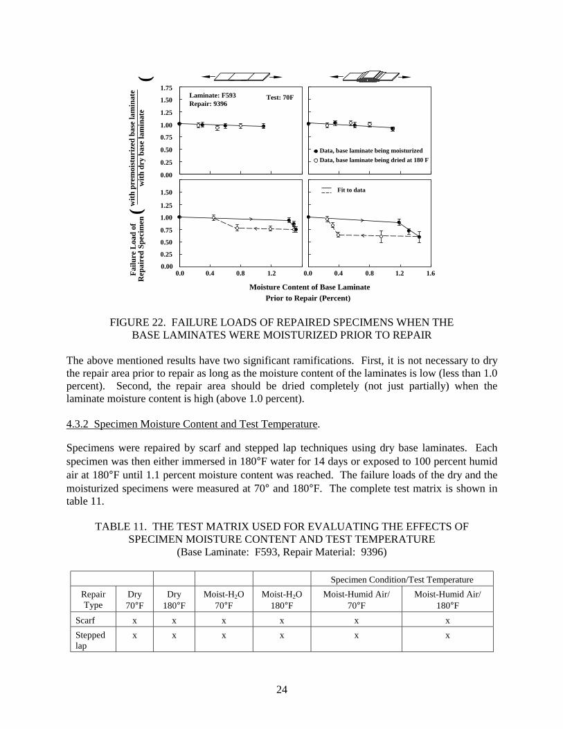
** Specimens were dried at 180°F after having been moisturized to either 1.1% or 1.5% moisture content. The failure loads of specimens repaired with premoisturized base laminates are given in figure 22. In this figure, the failure loads are normalized with respect to the failure load of the dry specimen. The following major observations can be made on the basis of the data in figure 22. • The failure loads of repaired specimens decreased only slightly when the base laminates
were moisturized prior to the repair, provided that the moisture content did not exceed 1.1 percent (see figure 22, top). This conclusion was valid when the base laminate moisture content was established either by moisturization (solid circle) or by moisturization followed by drying (open circle).
• The behavior was quite different when the moisture content of the base laminates
exceeded about 1.1 percent (see figure 22, bottom). The same phenomenon was observed by Robson, et al. [32] in their tests with scarf joints. The failure loads of repaired specimens made with base laminates which have first been moisturized to 1.5 percent moisture content then dried (dotted line in figure 22 bottom) were lower than the failure loads of repaired specimens made with base laminates in which the moisture was introduced during moisturization (solid line). In fact, the base laminates had to be dried almost completely to recover the failure loads of specimens made with premoisturized (but not dried) base laminates. Similar observations were made by Parker [33] on adhesively bonded single lap joints.
24
0.00
0.25
0.50
0.75
1.00
1.25
1.50
1.75Laminate: F593Repair: 9396
Test: 70F
Fit to data
Data, base laminate being moisturized
Data, base laminate being dried at 180 F
0.00
0.25
0.50
0.75
1.00
1.25
1.50
0.0 0.4 0.8 1.2 0.0 0.4 0.8 1.2 1.6
Moisture Content of Base Laminate Prior to Repair (Percent)
wit
h pr
emoi
stur
ized
bas
e la
min
ate
wit
h dr
y ba
se la
min
ate
F
ailu
re L
oad
ofR
epai
red
Spec
imen
(
(
FIGURE 22. FAILURE LOADS OF REPAIRED SPECIMENS WHEN THE BASE LAMINATES WERE MOISTURIZED PRIOR TO REPAIR
The above mentioned results have two significant ramifications. First, it is not necessary to dry the repair area prior to repair as long as the moisture content of the laminates is low (less than 1.0 percent). Second, the repair area should be dried completely (not just partially) when the laminate moisture content is high (above 1.0 percent). 4.3.2 Specimen Moisture Content and Test Temperature.
Specimens were repaired by scarf and stepped lap techniques using dry base laminates. Each specimen was then either immersed in 180°F water for 14 days or exposed to 100 percent humid air at 180°F until 1.1 percent moisture content was reached. The failure loads of the dry and the moisturized specimens were measured at 70° and 180°F. The complete test matrix is shown in table 11.
TABLE 11. THE TEST MATRIX USED FOR EVALUATING THE EFFECTS OF SPECIMEN MOISTURE CONTENT AND TEST TEMPERATURE
(Base Laminate: F593, Repair Material: 9396)
Specimen Condition/Test Temperature Repair Type
Dry 70°F
Dry 180°F
Moist-H2O 70°F
Moist-H2O 180°F
Moist-Humid Air/ 70°F
Moist-Humid Air/ 180°F
Scarf x x x x x x Stepped lap
x x x x x x
27
Vacuum
Surface breather
Heating blanket
Insulation
Edge bleeder
Solid FEP parting film
Aluminum plate
Surface bleeder
Microdielectricsensor
Composite plate
Repairedpart
Solid FEP parting film
Vacuumbag
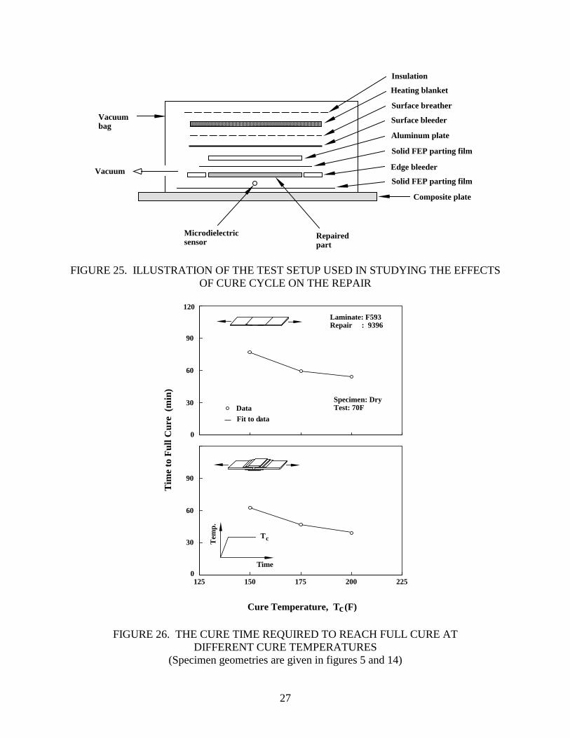
FIGURE 25. ILLUSTRATION OF THE TEST SETUP USED IN STUDYING THE EFFECTS
OF CURE CYCLE ON THE REPAIR
0
30
60
90
120
0
30
60
90
2.0
125 150 175 200 225
Cure Temperature, T (F)
Laminate: F593Repair : 9396
Specimen: DryTest: 70FData
Fit to data
c
Time
Tem
p.
Tc
Tim
e to
Ful
l Cur
e (
min
)
FIGURE 26. THE CURE TIME REQUIRED TO REACH FULL CURE AT DIFFERENT CURE TEMPERATURES
(Specimen geometries are given in figures 5 and 14)
28
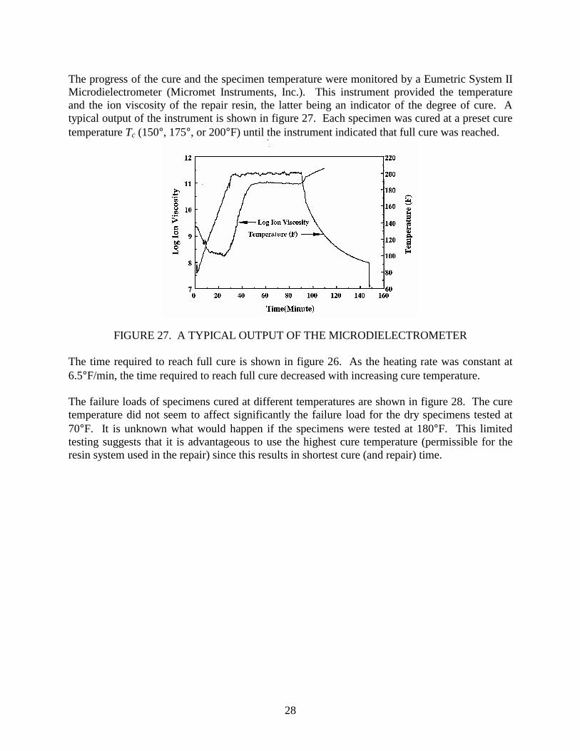
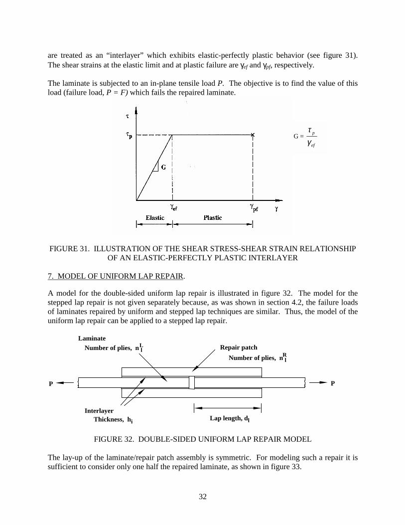
The progress of the cure and the specimen temperature were monitored by a Eumetric System II Microdielectrometer (Micromet Instruments, Inc.). This instrument provided the temperature and the ion viscosity of the repair resin, the latter being an indicator of the degree of cure. A typical output of the instrument is shown in figure 27. Each specimen was cured at a preset cure temperature Tc (150°, 175°, or 200°F) until the instrument indicated that full cure was reached.
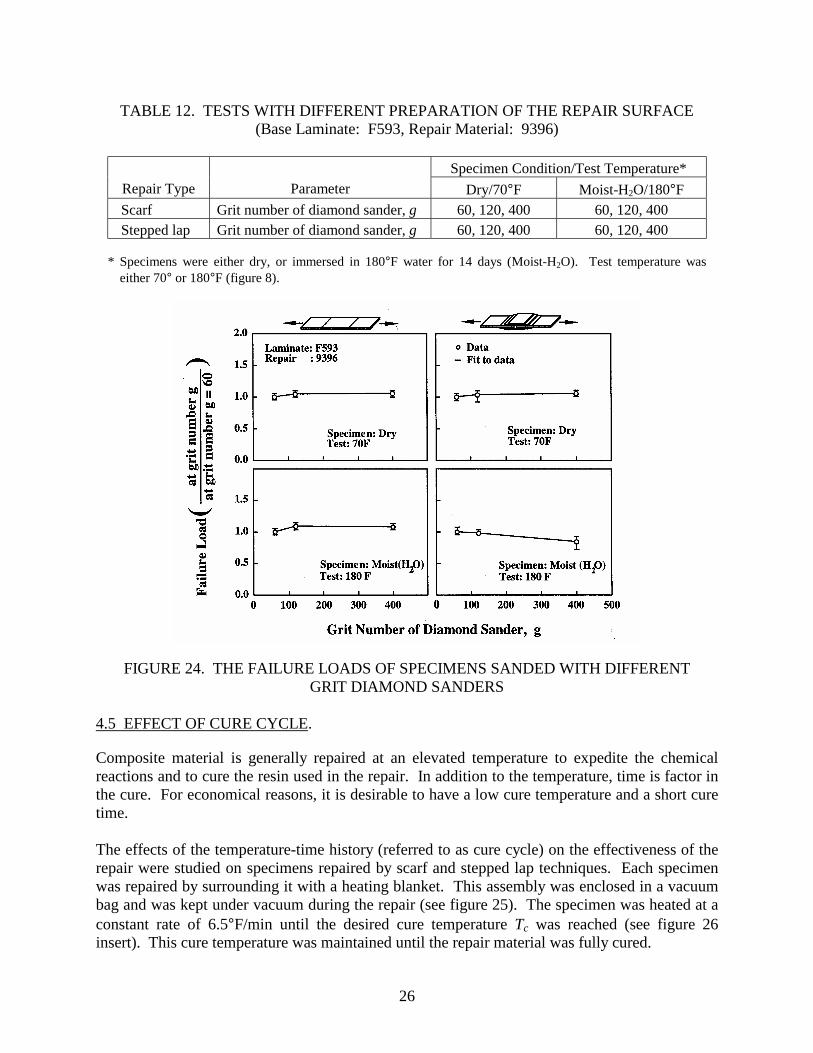
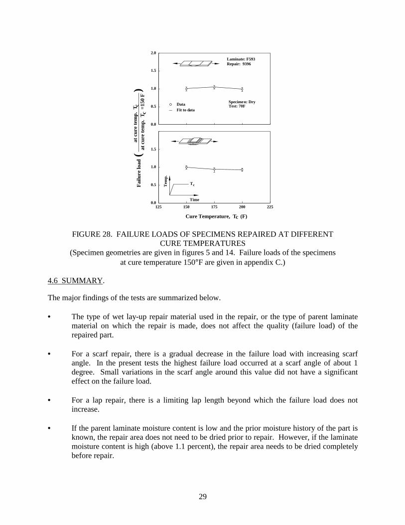
FIGURE 27. A TYPICAL OUTPUT OF THE MICRODIELECTROMETER The time required to reach full cure is shown in figure 26. As the heating rate was constant at 6.5°F/min, the time required to reach full cure decreased with increasing cure temperature. The failure loads of specimens cured at different temperatures are shown in figure 28. The cure temperature did not seem to affect significantly the failure load for the dry specimens tested at 70°F. It is unknown what would happen if the specimens were tested at 180°F. This limited testing suggests that it is advantageous to use the highest cure temperature (permissible for the resin system used in the repair) since this results in shortest cure (and repair) time.

31
Laminate
Repair patch
External plies
(b) Scarf repair without external ply
(c) Scarf repair with external plies
(a) Uniform lap repairP
PLaminate
Repair patch
P
P
P
P
Repair patch
Laminate
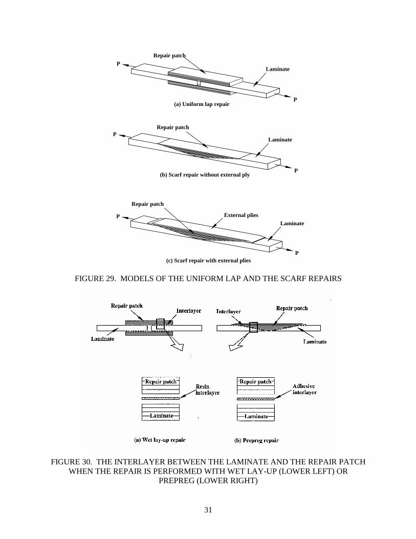
FIGURE 29. MODELS OF THE UNIFORM LAP AND THE SCARF REPAIRS
FIGURE 30. THE INTERLAYER BETWEEN THE LAMINATE AND THE REPAIR PATCH
WHEN THE REPAIR IS PERFORMED WITH WET LAY-UP (LOWER LEFT) OR PREPREG (LOWER RIGHT)
33
P
P/2
P/2
Repair patch
Laminate
Interlayer
Repair patch
x
P P
Laminate
Repair patch
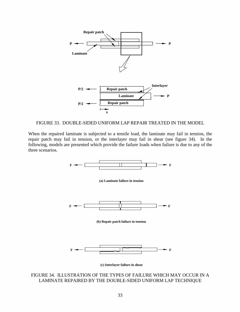
FIGURE 33. DOUBLE-SIDED UNIFORM LAP REPAIR TREATED IN THE MODEL When the repaired laminate is subjected to a tensile load, the laminate may fail in tension, the repair patch may fail in tension, or the interlayer may fail in shear (see figure 34). In the following, models are presented which provide the failure loads when failure is due to any of the three scenarios.
(a) Laminate failure in tension
(b) Repair patch failure in tension
(c) Interlayer failure in shear
F
F
FF
F
F
FIGURE 34. ILLUSTRATION OF THE TYPES OF FAILURE WHICH MAY OCCUR IN A LAMINATE REPAIRED BY THE DOUBLE-SIDED UNIFORM LAP TECHNIQUE
36
Interlayer, I
Laminate, L
Repair patch, R
NR
NR
NR + dx
NR + dx
NL
dx
NL + dx
τ dx
dNL
dx
dNR
dx
dNR
dxR
R
L
I
I
P
P/2
P/2
x
dx
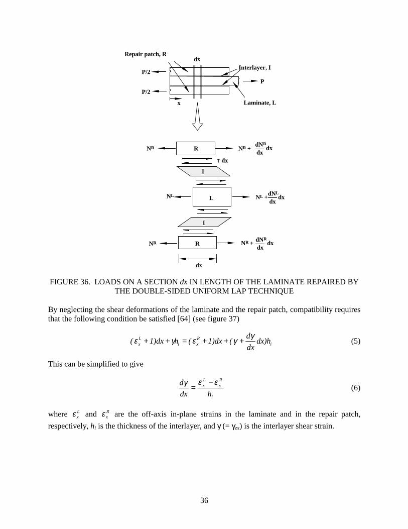
FIGURE 36. LOADS ON A SECTION dx IN LENGTH OF THE LAMINATE REPAIRED BY
THE DOUBLE-SIDED UNIFORM LAP TECHNIQUE By neglecting the shear deformations of the laminate and the repair patch, compatibility requires that the following condition be satisfied [64] (see figure 37)
iRxi
Lx dx)h
dxd(1)dx(h1)dx( γγεγε +++=++ (5)
This can be simplified to give
i
Rx
Lx
hdxd εεγ −
= (6)
where L
xε and Rxε are the off-axis in-plane strains in the laminate and in the repair patch,
respectively, hi is the thickness of the interlayer, and γ (= γzx) is the interlayer shear strain.
37
(1+εR)dx
γ
dγ dxγ +dx
(1+εL)dx
h
L
R
R
I
I
Interlayer
Laminate
Repair patch
x
x
i
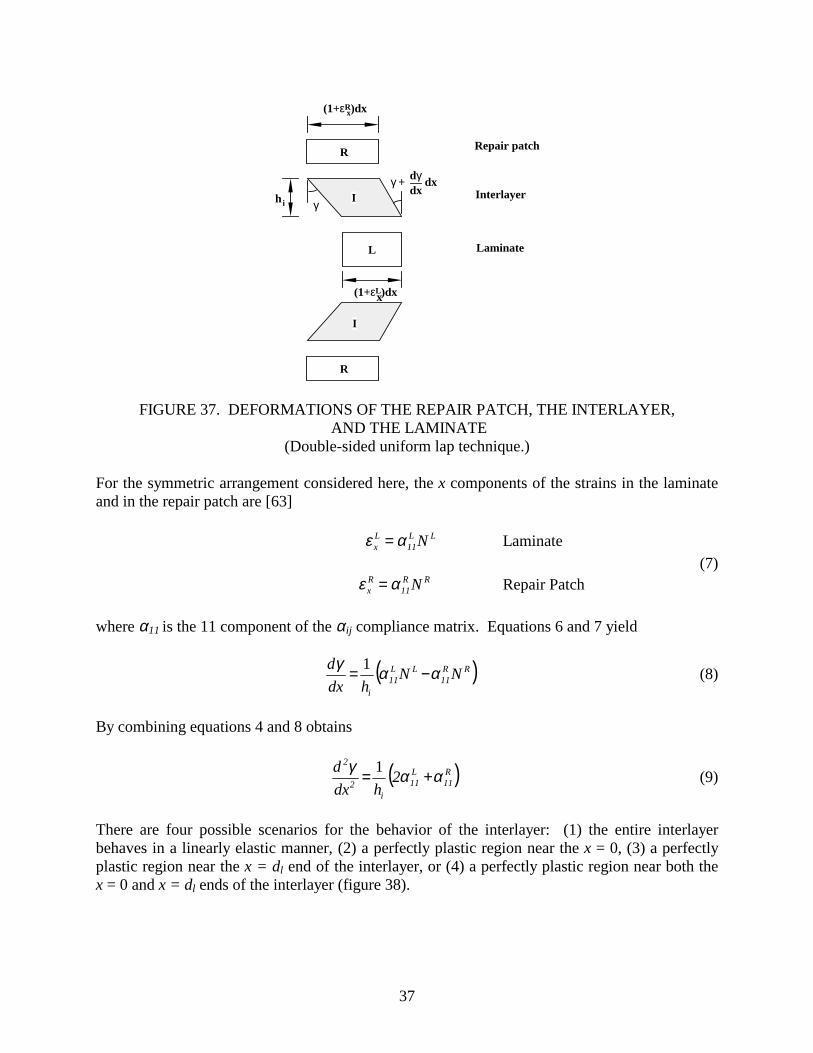
FIGURE 37. DEFORMATIONS OF THE REPAIR PATCH, THE INTERLAYER, AND THE LAMINATE
(Double-sided uniform lap technique.) For the symmetric arrangement considered here, the x components of the strains in the laminate and in the repair patch are [63] LL
11Lx N αε = Laminate
(7) RR
11Rx N αε = Repair Patch
where α11 is the 11 component of the αij compliance matrix. Equations 6 and 7 yield
( )RR11
LL11
i
NNh
dxd ααγ −= 1 (8)
By combining equations 4 and 8 obtains
( )R11
L11
i2
2
2h
dxd ααγ += 1 (9)
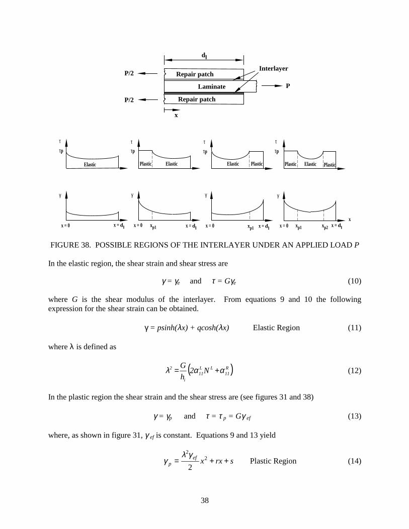
There are four possible scenarios for the behavior of the interlayer: (1) the entire interlayer behaves in a linearly elastic manner, (2) a perfectly plastic region near the x = 0, (3) a perfectly plastic region near the x = dl end of the interlayer, or (4) a perfectly plastic region near both the x = 0 and x = dl ends of the interlayer (figure 38).
38
γ
τ
x = dlx = 0
τp
γ
τ
x
τp
Plastic Elastic Plastic
γ
τ
τp
ElasticElastic PlasticPlastic
x = dlx = 0 x = dlx = 0xp1 xp1 xp1 xp2
γ
τ
x = dlx = 0
τp
Elastic
P
P/2
P/2
Interlayer
x
dl
Repair patch
Laminate
Repair patch
FIGURE 38. POSSIBLE REGIONS OF THE INTERLAYER UNDER AN APPLIED LOAD P
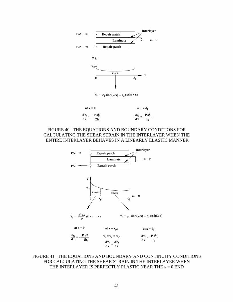
In the elastic region, the shear strain and shear stress are γ = γe and τ = Gγe (10) where G is the shear modulus of the interlayer. From equations 9 and 10 the following expression for the shear strain can be obtained. γ = psinh(λx) + qcosh(λx) Elastic Region (11) where λ is defined as
( )R11
LL11
i
2 N2hG ααλ += (12)
In the plastic region the shear strain and the shear stress are (see figures 31 and 38) γ = γp and τ = τ p = Gγ ef (13) where, as shown in figure 31, γ ef is constant. Equations 9 and 13 yield
srxxefp ++= 2
2
2γλ
γ Plastic Region (14)
39
In equations 11 and 14, p, q, r, and s are constants which must be determined from the boundary and continuity conditions. 7.2.1 Boundary and Continuity Conditions.
The following are the boundary and continuity conditions for to equations 11 and 14. • At the free ends of the laminate and the repair patches, the axial load is zero (see figure
39) NL = 0 at 0x = NR = 0 at ldx = (15) • At the ends of the laminate and the repair patches where loads are applied (see figure 39),
the load per unit width NL in the laminate is equal to the applied load per unit width P, and the load per unit width NR in each repair patch is equal to P/2
2PN R = at 0x =
(16) PN L = at ldx = By combining equations 8, 15, and 16, these boundary conditions can be expressed as
i
R
hP
dxd
211αγ
−= at 0x = (17)
and
i
L
hP
dxd 11αγ = at ldx = (18)
In equations 17 and 18 dxdγ is either
dxedγ or
dxpdγ depending on whether the interlayer is in the
elastic or in the perfectly plastic region at the boundary (see figures 40 through 43).
40
P/2
P/2
Laminate
Repair patch
Repair patch
NL =
NR = 0
NL =
NR =
0
NR =
P
Laminate
Repair patch
x
x
dl
γ
xxp1
γe
γpγp
xp2
γpγe = = γef
ddxγe d
dxγp
=
NR = 0
at x=0 at x=dl
P
x=xp1 xp2 x=at and
Plastic Elastic Plastic
γef
P
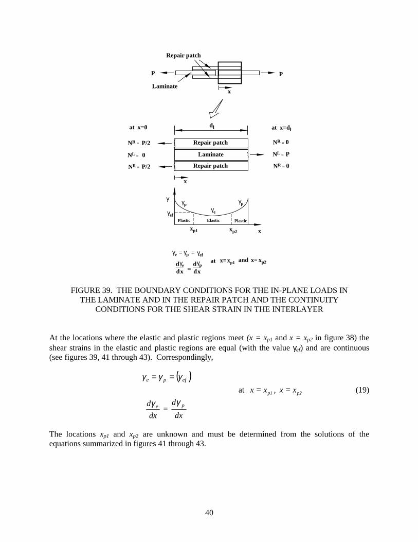
FIGURE 39. THE BOUNDARY CONDITIONS FOR THE IN-PLANE LOADS IN THE LAMINATE AND IN THE REPAIR PATCH AND THE CONTINUITY
CONDITIONS FOR THE SHEAR STRAIN IN THE INTERLAYER
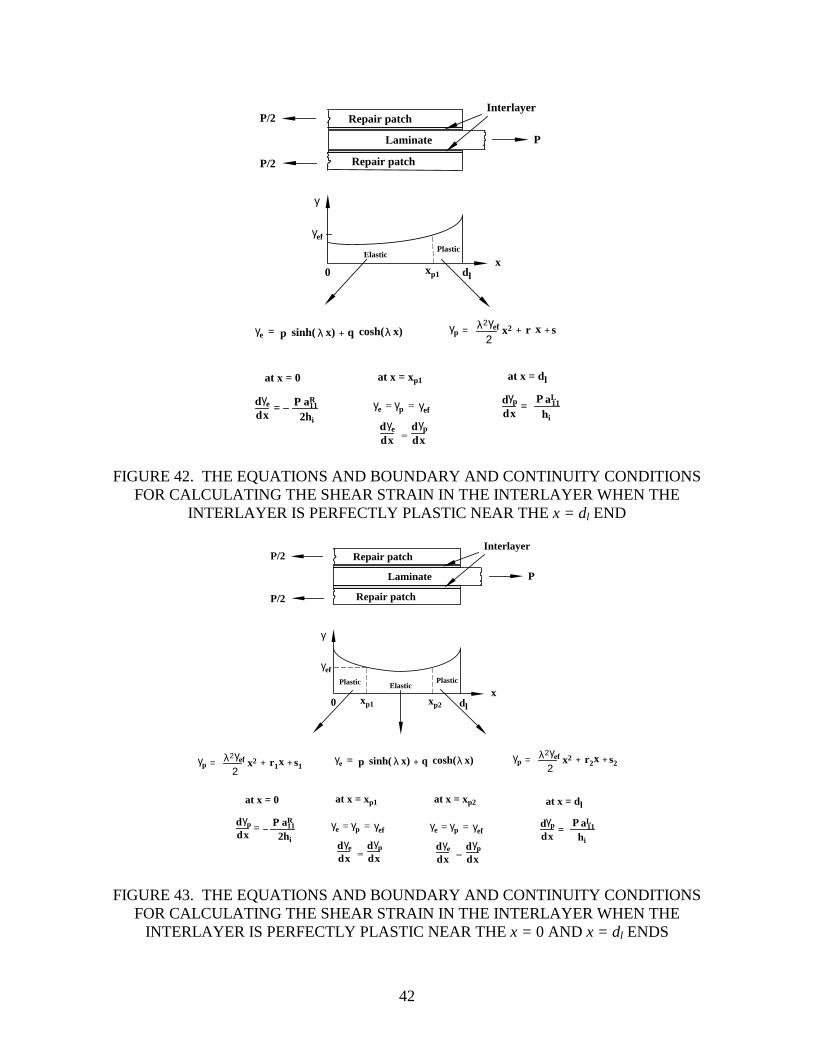
At the locations where the elastic and plastic regions meet (x = xp1 and x = xp2 in figure 38) the shear strains in the elastic and plastic regions are equal (with the value γef) and are continuous (see figures 39, 41 through 43). Correspondingly, ( )efpe γγγ == at p1xx = , p2xx = (19)
dx
d eγ =
dxd pγ
The locations xp1 and xp2 are unknown and must be determined from the solutions of the equations summarized in figures 41 through 43.
41
γe = c1 +sinh( λ x) c2 cosh(λ x)
dd
aR11
x=
2hi
P aLddx
11=hi
P
γ
xElastic
γef
0
at x = dlat x = 0
γe γe
P
P/2
P/2
InterlayerRepair patch
Laminate
Repair patch
dl
FIGURE 40. THE EQUATIONS AND BOUNDARY CONDITIONS FOR CALCULATING THE SHEAR STRAIN IN THE INTERLAYER WHEN THE ENTIRE INTERLAYER BEHAVES IN A LINEARLY ELASTIC MANNER
γp = λ2γef
2x2 r + sx+ γe = p +sinh( λ x) q cosh(λ x)
dd
aR11
x=
2hi
Pγp aLddx
11=hi
Pγpγe = = γef
ddxγe d
dxγp
=
γ
xxp1
Plastic Elastic
γef
0
at x = dlat x = xp1at x = 0
γe
P
P/2
P/2
InterlayerRepair patch
Laminate
Repair patch
dl
FIGURE 41. THE EQUATIONS AND BOUNDARY AND CONTINUITY CONDITIONS FOR CALCULATING THE SHEAR STRAIN IN THE INTERLAYER WHEN
THE INTERLAYER IS PERFECTLY PLASTIC NEAR THE x = 0 END
42
γp = λ2γef
2x2 r + sx+γe = p +sinh( λ x) q cosh(λ x)
dd
aR11
x=
2hi
P aLddx
11=hi
Pγpγpγe = = γef
ddxγe d
dxγp
=
γ
xxp1
ElasticPlastic
γef
dl0
at x = dlat x = xp1at x = 0
γe
P
P/2
P/2
InterlayerRepair patch
Laminate
Repair patch
FIGURE 42. THE EQUATIONS AND BOUNDARY AND CONTINUITY CONDITIONS FOR CALCULATING THE SHEAR STRAIN IN THE INTERLAYER WHEN THE
INTERLAYER IS PERFECTLY PLASTIC NEAR THE x = dl END
γp = λ2γef
2x2 r1 + s1x+ γp = λ2γef
2x2 r2 + s2x+γe = p +sinh( λ x) q cosh(λ x)
dd
aR11
x=
2hi
Pγp aLddx
11=hi
Pγpγpγe = = γef
ddxγe d
dxγp
=
γpγe = = γef
ddxγe d
dxγp
=
γ
xxp1 xp2
Plastic ElasticPlastic
γef
dl0
at x = dlat x = xp1at x = 0 at x = xp2
P
P/2
P/2
InterlayerRepair patch
Laminate
Repair patch
FIGURE 43. THE EQUATIONS AND BOUNDARY AND CONTINUITY CONDITIONS FOR CALCULATING THE SHEAR STRAIN IN THE INTERLAYER WHEN THE
INTERLAYER IS PERFECTLY PLASTIC NEAR THE x = 0 AND x = dl ENDS
44
P P
Repair patch
Scarf length, ds
(a) Without external ply
(b) With external plies
Overlap length of external plies
P P
Laminate
Repair patch
Interlayer Scarf length, ds
Overlap length per ply, dso
External plies
Number of plies, n lL
Number of plies, n lR
Thickness, hi
Number of plies, ne
dede
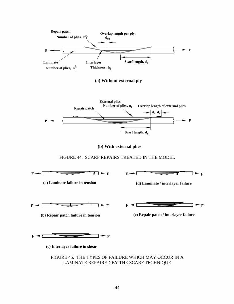
FIGURE 44. SCARF REPAIRS TREATED IN THE MODEL
(a) Laminate failure in tension
(b) Repair patch failure in tension
F F
(c) Interlayer failure in shear
F F
F F
(d) Laminate / interlayer failure
F F
(e) Repair patch / interlayer failure
F F
FIGURE 45. THE TYPES OF FAILURE WHICH MAY OCCUR IN A LAMINATE REPAIRED BY THE SCARF TECHNIQUE
46
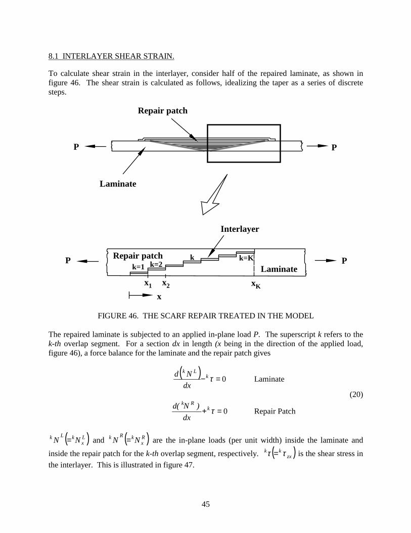
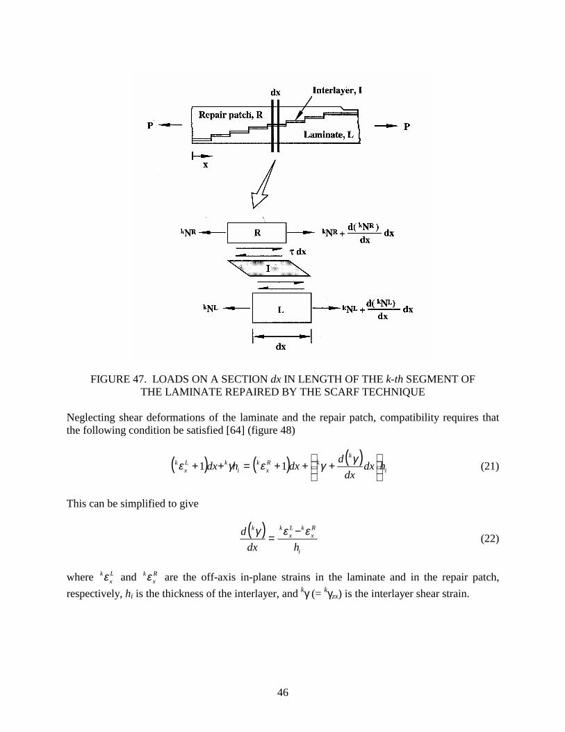
FIGURE 47. LOADS ON A SECTION dx IN LENGTH OF THE k-th SEGMENT OF THE LAMINATE REPAIRED BY THE SCARF TECHNIQUE
Neglecting shear deformations of the laminate and the repair patch, compatibility requires that the following condition be satisfied [64] (figure 48)
( ) ( ) ( )i
kkR
xk
ikL
xk hdx
dxddxhdx
+++=++ γγεγε 11 (21)
This can be simplified to give
( )i
Rx
kLx
kk
hdxd εεγ −= (22)
where L
xkε and R
xkε are the off-axis in-plane strains in the laminate and in the repair patch,
respectively, hi is the thickness of the interlayer, and kγ (= kγzx) is the interlayer shear strain.
47
(1+ kεR) dx
kγ
d( kγ)dx
dx
(1+ kεL) dx
hi
L
R
I Interlayer
Laminate
Repair patch
kγ +
x
x
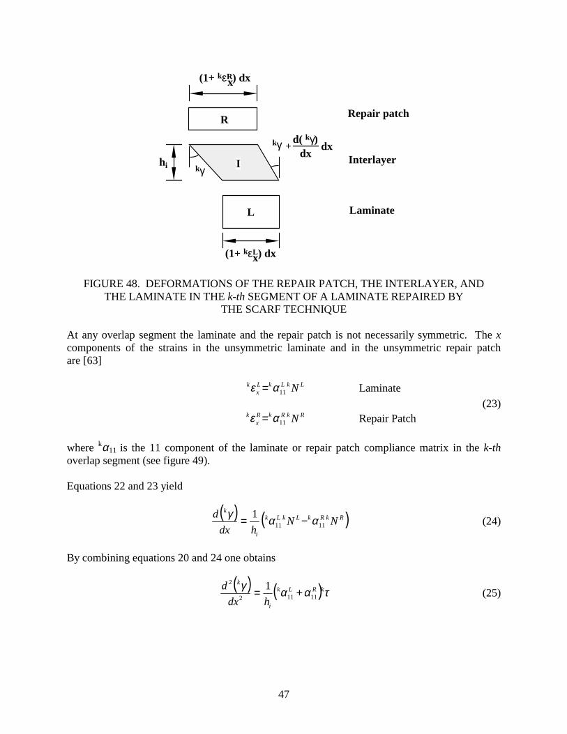
FIGURE 48. DEFORMATIONS OF THE REPAIR PATCH, THE INTERLAYER, AND THE LAMINATE IN THE k-th SEGMENT OF A LAMINATE REPAIRED BY
THE SCARF TECHNIQUE At any overlap segment the laminate and the repair patch is not necessarily symmetric. The x components of the strains in the unsymmetric laminate and in the unsymmetric repair patch are [63] LkLkL
xk N11αε = Laminate
(23) RkRkR
xk N11αε = Repair Patch
where kα11 is the 11 component of the laminate or repair patch compliance matrix in the k-th overlap segment (see figure 49). Equations 22 and 23 yield
( ) ( )RkRkLkLk
i
k
NNhdx
d1111
1 ααγ −= (24)
By combining equations 20 and 24 one obtains
( ) ( ) τααγ kRLk
i
k
hdxd
11112
2 1 += (25)

48
FIGURE 49. THE COMPLIANCE MATRICES IN THE LAMINATE AND THE REPAIR PATCH
There are four possible scenarios for the behavior of the interlayer (see figure 50). The entire interlayer behaves in a linearly elastic manner, there is a perfectly plastic region either near the x = 0 or near the x = xK end of the repair patch, or there are perfectly plastic regions near both the x = 0 and x = xK ends of the repair patch (xK is defined in figure 46).
Interlayer
Laminate
Repair patch
P P
Elastic Elastic Elastic ElasticPlastic Plastic PlasticPlastic
x=0 x=xK
FIGURE 50. POSSIBLE REGIONS OF THE INTERLAYER UNDER AN APPLIED LOAD P
(From left to the right: interlayer is linearly elastic; interlayer is perfectly plastic near the x = 0 end; interlayer is perfectly plastic near the x = xK end; and interlayer is
perfectly plastic near the x = 0 and x = xK ends. (Scarf technique)) In the elastic region, the shear strain and shear stress are e
kk γγ= and ekk G γτ = (26)
where G is the shear modulus of the interlayer. From equations 25 and 26 the following expression for the shear strain is obtained ( ) ( )xcoshqxsinhp kkkk
ek λλγ += Elastic Region (27)
where kλ is defined as
( ) ( )RkLk
i
k
hG
11112 ααλ += (28)
49
In the plastic region the shear strain and shear stress are (see figure 31) p
kk γγ= and efpkk Gγττ == (29)
where, as shown in figure 31, γef is constant. Equations 25 and 29 yield
( )
srxx kkefk
pk ++= 2
2
2γλ
γ Plastic Region (30)
In equations 27 and 30, kp, kq, kr, and ks are constants which must be determined from the boundary and continuity conditions. 8.1.1 Boundary and Continuity Conditions.
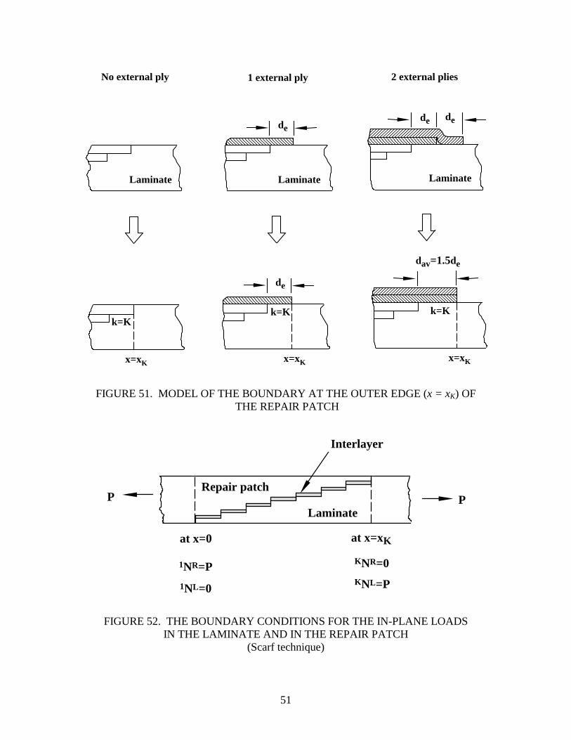
The terminations of the external plies are modeled as illustrated in figure 51. Then, the boundary and continuity conditions corresponding to equations 27 and 30 are as follows.
• At the inside edge of the repair patch (x = 0) the axial load (per unit width) is zero in the
laminate, and is equal to the applied load (per unit width) P in the repair patch (see figure 52). At the outside edge of the repair (x = xK) the axial load (per unit width) is zero in the repair patch, and is equal to the applied load (per unit width) P in the laminate
1NL = 0 at x = 0 (31) lNR = P KNL = P at x = xK (32) KNR = 0
By combining equations 24, 31, and 32, these boundary conditions can be expressed as
( )i
R
hP
dxd 11
11 αγ −= at x=0, (33)
and
( )
=
i
LkK
hP
dxd 11αγ
at x = xK (34)
In equations 33 and 34 kγ is either kγe or kγp depending on whether the interlayer is in the elastic or in the perfectly plastic region at the boundary.
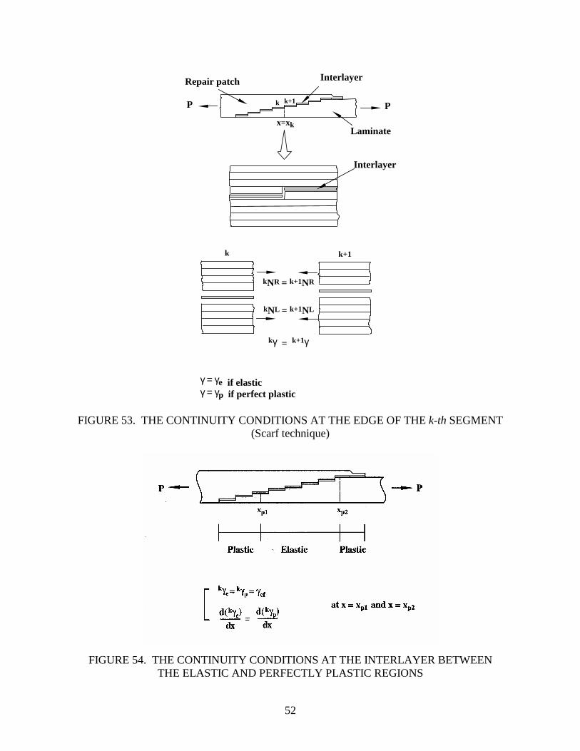
• At the edge of each overlap segment (at x = xK, figure 53) the shear strain in the interlayer is continuous and the in-plane loads are equal and opposite on the left and right sides of the segment. It is assumed that the load is transmitted only by continuous layers
50
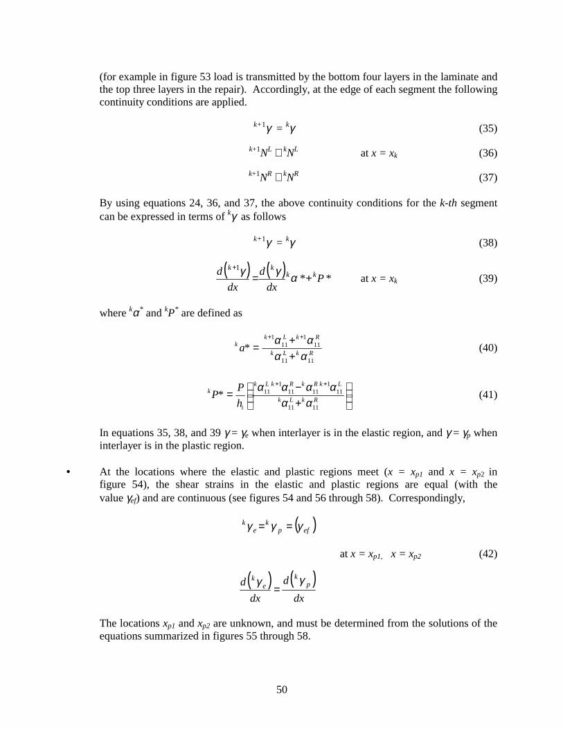
(for example in figure 53 load is transmitted by the bottom four layers in the laminate and the top three layers in the repair). Accordingly, at the edge of each segment the following continuity conditions are applied.
k+1γ = kγ (35)
k+1NL ≅ kNL at x = xk (36)
k+1NR ≅ kNR (37)
By using equations 24, 36, and 37, the above continuity conditions for the k-th segment can be expressed in terms of kγ as follows
k+1γ = kγ (38)
( ) ( ) *P*
dxd
dxd kk
kk+=
+αγγ1
at x = xk (39)
where kα* and kP* are defined as
RkLk
RkLkk *a
1111
111
111
αααα
++
=++
(40)
+−=
++
RkLk
LkRkRkLk
i
k
hP*P
1111
111
11111
11
αααααα
(41)
In equations 35, 38, and 39 γ = γe when interlayer is in the elastic region, and γ = γp when interlayer is in the plastic region.
• At the locations where the elastic and plastic regions meet (x = xp1 and x = xp2 in
figure 54), the shear strains in the elastic and plastic regions are equal (with the value γef) and are continuous (see figures 54 and 56 through 58). Correspondingly,
( )efp
ke
k γγγ ==
at x = xp1, x = xp2 (42)
( ) ( )
dxd
dxd p
ke
k γγ=
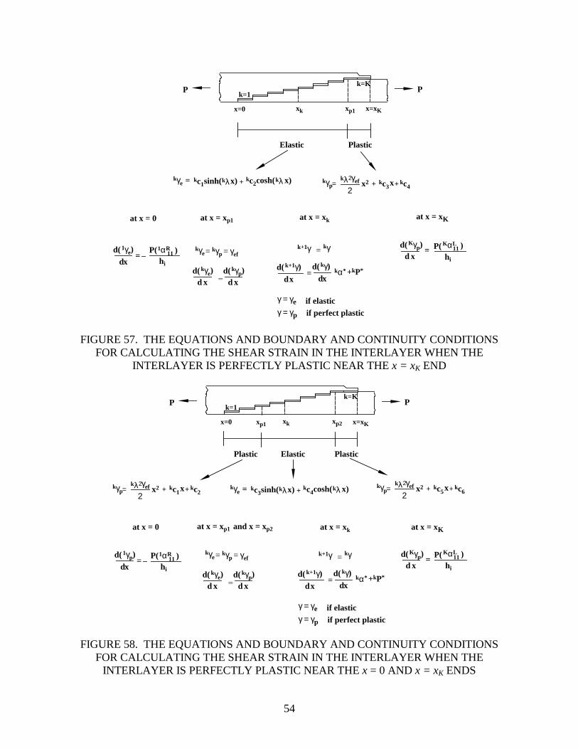
The locations xp1 and xp2 are unknown, and must be determined from the solutions of the equations summarized in figures 55 through 58.
51
Laminate Laminate Laminate
No external ply 1 external ply 2 external plies
k=Kk=Kk=K
de
dav=1.5de
dede
de
x=xKx=xKx=xK
FIGURE 51. MODEL OF THE BOUNDARY AT THE OUTER EDGE (x = xK) OF THE REPAIR PATCH
Interlayer
Laminate
Repair patch
at x=xKat x=0
KNR=0
KNL=P1NL=0
1NR=P
P P
FIGURE 52. THE BOUNDARY CONDITIONS FOR THE IN-PLANE LOADS IN THE LAMINATE AND IN THE REPAIR PATCH
(Scarf technique)
52
Interlayer
kNR = k+1NR
kNL = k+1NL
k+1γkγ =
Interlayer
Laminate
Repair patch
P P
x=xk
k k+1
γ = γe if elasticγ = γp if perfect plastic
k k+1
FIGURE 53. THE CONTINUITY CONDITIONS AT THE EDGE OF THE k-th SEGMENT (Scarf technique)
FIGURE 54. THE CONTINUITY CONDITIONS AT THE INTERLAYER BETWEEN THE ELASTIC AND PERFECTLY PLASTIC REGIONS

53
P P
x=0 x=xKxk
Elastic
kγe = kp +sinh(kλx) kq cosh(kλ x)
d(dx
1γe) 1αR11P(
hi
)=
at x = 0
KαL11
hi
P( )d x
=d( Kγe)
at x = xKat x = xk
k+1γekγe =
= kα*d(dx
k+1γe) d(dx
kγe) +kP*
k=1
k=K
FIGURE 55. THE EQUATIONS AND BOUNDARY CONDITIONS FOR CALCULATING THE SHEAR STRAIN IN THE INTERLAYER WHEN THE ENTIRE INTERLAYER
BEHAVES IN A LINEARLY ELASTIC MANNER
Elastic
kγe = kp +sinh(kλx) kq cosh(kλ x)
at x = 0 at x = xKat x = xk
kγp=kλ2γef
2x2 kr + ksx+
at x = xp1
xp1
Plastic
d(dx
1γp)=
kγpkγe= = γef
=
d x=
d( Kγp)
d xd( kγp)
d xd( kγe) =
k+1γ kγ=
kα*d(dx
k+1γ) d(dx
kγ)+kP*
γ = γe if elasticγ = γp if perfect plastic
1αR11P(
hi
) KαL11
hi
P( )
P P
x=0 x=xKxk
k=1
k=K
FIGURE 56. THE EQUATIONS AND BOUNDARY AND CONTINUITY CONDITIONS FOR CALCULATING THE SHEAR STRAIN IN THE INTERLAYER WHEN THE
INTERLAYER IS PERFECTLY PLASTIC NEAR THE x = 0 END
54
Elastic
kγe = kc1 +sinh(kλx) kc2cosh(kλ x)
at x = 0 at x = xKat x = xk
kγp=kλ2γef
2x2 kc3 + kc4x+
kγpkγe= = γef
=
at x = xp1
xp1
Plastic
d(dx
1γe) = d x=
d( Kγp)
d xd( kγp)
d xd( kγe) =
k+1γ kγ=
kα*d(dx
k+1γ) d(dx
kγ)+kP*
γ = γe if elasticγ = γp if perfect plastic
KαL11
hi
P( )1αR11P(
hi
)
P P
x=0 x=xKxk
k=1
k=K
FIGURE 57. THE EQUATIONS AND BOUNDARY AND CONTINUITY CONDITIONS FOR CALCULATING THE SHEAR STRAIN IN THE INTERLAYER WHEN THE
INTERLAYER IS PERFECTLY PLASTIC NEAR THE x = xK END
Elastic
kγe = kc3 +sinh(kλx) kc4cosh(kλ x)
at x = 0 at x = xKat x = xk
kγp=kλ2γef
2x2 kc1 + kc2x+
at x = xp1
xp1
Plastic
xp2
Plastic
and x = xp2
kγp=kλ2γef
2x2 kc5 + kc6x+
d(dx
1γp)=
kγpkγe= = γef
= d xd( kγp)
d xd( kγe)
d x=
d( Kγp)
=
k+1γ kγ=
kα*d(dx
k+1γ) d(dx
kγ)+kP*
γ = γe if elasticγ = γp if perfect plastic
1αR11P(
hi
) KαL11
hi
P( )
P P
x=0 x=xKxk
k=1
k=K
FIGURE 58. THE EQUATIONS AND BOUNDARY AND CONTINUITY CONDITIONS FOR CALCULATING THE SHEAR STRAIN IN THE INTERLAYER WHEN THE
INTERLAYER IS PERFECTLY PLASTIC NEAR THE x = 0 AND x = xK ENDS
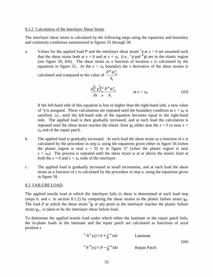
56
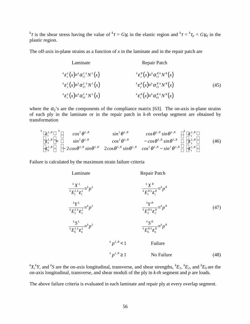
kτ is the shear stress having the value of kτ = Gγe in the elastic region and kτ = kτp = Gγef in the plastic region. The off-axis in-plane strains as a function of x in the laminate and in the repair patch are Laminate Repair Patch ( ) ( )xNx LkLkL
xk
11αε = ( ) ( )xNx RkRkRx
k11αε =
( ) ( )xNx LkLkLy
k21αε = ( ) ( )xNx RkRkR
yk
21αε = (45)
( ) ( )xNx LkLkLs
k61αε = ( ) ( )xNx RkRkR
sk
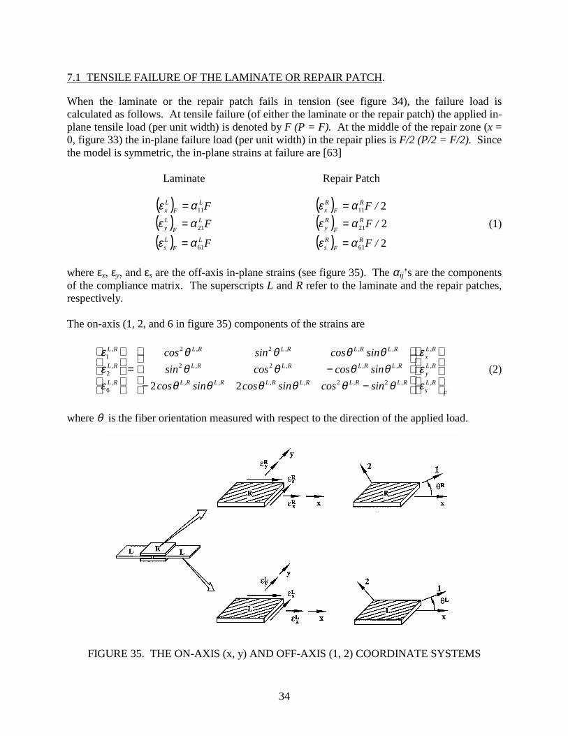
61αε = where the αij’s are the components of the compliance matrix [63]. The on-axis in-plane strains of each ply in the laminate or in the repair patch in k-th overlap segment are obtained by transformation
−−−=
R,Ls
R,Ly
R,Lx
k
R,LR,LR,LR,LR,LR,L
R,LR,LR,LR,L
R,LR,LR,LR,Lk
R,L
R,L
R,Lk
sincossincossincossincoscossin
sincossincos
εεε
θθθθθθθθθθ
θθθθ
εεε
22
22
22
6
2
1
22 (46)
Failure is calculated by the maximum strain failure criteria Laminate Repair Patch
LkLkLk
Lk
pE
X =11 ε
RkRkRk
Rk
pE
X =11 ε
LkLkLk
Lk
pE
Y =22 ε
RkRkRk
Rk
pE
Y =22 ε
(47)
LkLkLk
Lk
pE
S =66 ε
RkRkRk
Rk
pE
S =66 ε
1<R,Lk p Failure
1≥R,Lk p No Failure (48) kX,kY, and kS are the on-axis longitudinal, transverse, and shear strengths, kE1, kE2, and kE6 are the on-axis longitudinal, transverse, and shear moduli of the ply in k-th segment and p are loads. The above failure criteria is evaluated in each laminate and repair ply at every overlap segment.
58
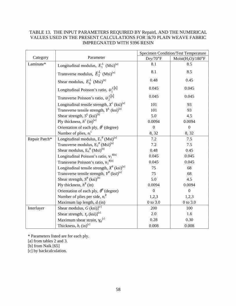
TABLE 13. THE INPUT PARAMETERS REQUIRED BY RepairL AND THE NUMERICAL VALUES USED IN THE PRESENT CALCULATIONS FOR 3k70 PLAIN WEAVE FABRIC
IMPREGNATED WITH 9396 RESIN
Specimen Condition/Test Temperature Category Parameter Dry/70°F Moist(H2O)/180°F
Laminate* Longitudinal modulus, LE1 (Msi)[a] 8.1 8.5
Transverse modulus, LE2 (Msi)[a] 8.1 8.5
Shear modulus, LE6 (Msi)[b] 0.48 0.45
Longitudinal Poisson’s ratio, [ ]bL1υ 0.045 0.045
Transverse Poisson’s ratio, [ ]bL2υ 0.045 0.045
Longitudinal tensile strength, XL (ksi)[a] 101 93 Transverse tensile strength, YL (ksi)[a] 101 93 Shear strength, SL (ksi)[b] 5.0 4.5 Ply thickness, hL (in)[a] 0.0094 0.0094 Orientation of each ply, θL (degree) 0 0 Number of plies, nl
L 8, 32 8, 32 Repair Patch* Longitudinal modulus, E1
R (Msi)[a] 7.2 7.5 Transverse modulus, E2
R (Msi)[a] 7.2 7.5 Shear modulus, E6
R (Msi)[b] 0.48 0.45 Longitudinal Poisson’s ratio, ν1
R[b] 0.045 0.045 Transverse Poisson’s ratio, ν2
R[b] 0.045 0.045 Longitudinal tensile strength, XR (ksi)[a] 75 68 Transverse tensile strength, YR (ksi)[a] 75 68 Shear strength, SR (ksi)[b] 5.0 4.5 Ply thickness, hR (in) 0.0094 0.0094 Orientation of each ply, θR (degree) 0 0 Number of plies per side, nl
R 1,2,3 1,2,3 Maximum lap length, dl (in) 0 to 3.0 0 to 3.0 Interlayer Shear modulus, G (ksi)][c] 200 100 Shear strength, τp (ksi)][c] 2.0 1.6 Maximum shear strain, γpf
[c] 0.28 0.30 Thickness, hi (in)[c] 0.008 0.008 * Parameters listed are for each ply. [a] from tables 2 and 3. [b] from Naik [65] [c] by backcalculation.
59
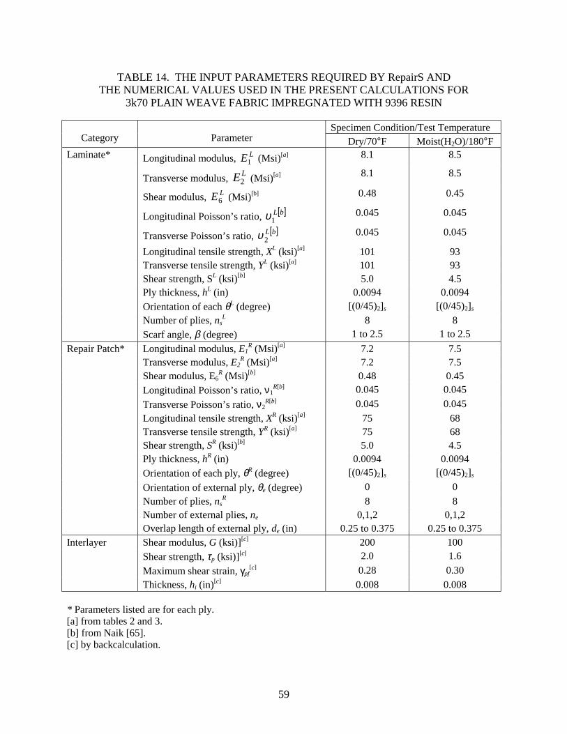
TABLE 14. THE INPUT PARAMETERS REQUIRED BY RepairS AND THE NUMERICAL VALUES USED IN THE PRESENT CALCULATIONS FOR
3k70 PLAIN WEAVE FABRIC IMPREGNATED WITH 9396 RESIN
Specimen Condition/Test Temperature Category Parameter Dry/70°F Moist(H2O)/180°F
Laminate* Longitudinal modulus, LE1 (Msi)[a] 8.1 8.5
Transverse modulus, LE2 (Msi)[a] 8.1 8.5
Shear modulus, LE6 (Msi)[b] 0.48 0.45
Longitudinal Poisson’s ratio, [ ]bL1υ 0.045 0.045
Transverse Poisson’s ratio, [ ]bL2υ 0.045 0.045
Longitudinal tensile strength, XL (ksi)[a] 101 93 Transverse tensile strength, YL (ksi)[a] 101 93 Shear strength, SL (ksi)[b] 5.0 4.5 Ply thickness, hL (in) 0.0094 0.0094 Orientation of each θL (degree) [(0/45)2]s [(0/45)2]s Number of plies, ns
L 8 8 Scarf angle, β (degree) 1 to 2.5 1 to 2.5 Repair Patch* Longitudinal modulus, E1
R (Msi)[a] 7.2 7.5 Transverse modulus, E2
R (Msi)[a] 7.2 7.5 Shear modulus, E6
R (Msi)[b] 0.48 0.45 Longitudinal Poisson’s ratio, ν1
R[b] 0.045 0.045 Transverse Poisson’s ratio, ν2
R[b] 0.045 0.045 Longitudinal tensile strength, XR (ksi)[a] 75 68 Transverse tensile strength, YR (ksi)[a] 75 68 Shear strength, SR (ksi)[b] 5.0 4.5 Ply thickness, hR (in) 0.0094 0.0094 Orientation of each ply, θR (degree) [(0/45)2]s [(0/45)2]s Orientation of external ply, θe (degree) 0 0 Number of plies, ns
R 8 8 Number of external plies, ne 0,1,2 0,1,2 Overlap length of external ply, de (in) 0.25 to 0.375 0.25 to 0.375 Interlayer Shear modulus, G (ksi)][c] 200 100 Shear strength, τp (ksi)][c] 2.0 1.6 Maximum shear strain, γpf
[c] 0.28 0.30 Thickness, hi (in)[c] 0.008 0.008 * Parameters listed are for each ply. [a] from tables 2 and 3. [b] from Naik [65]. [c] by backcalculation.
60
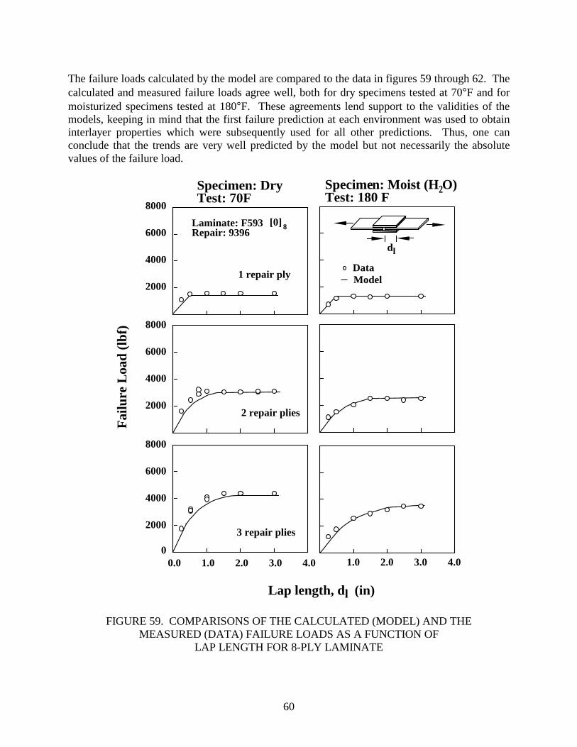
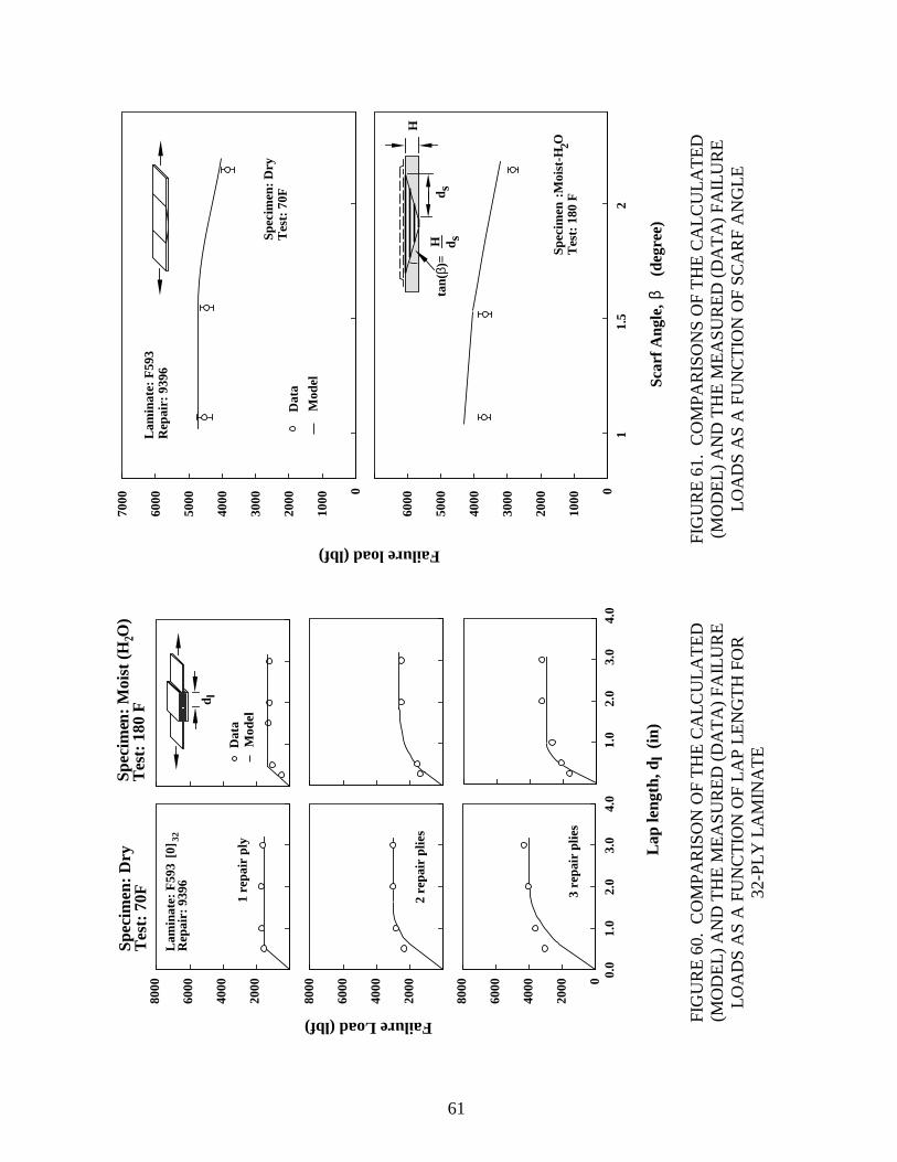
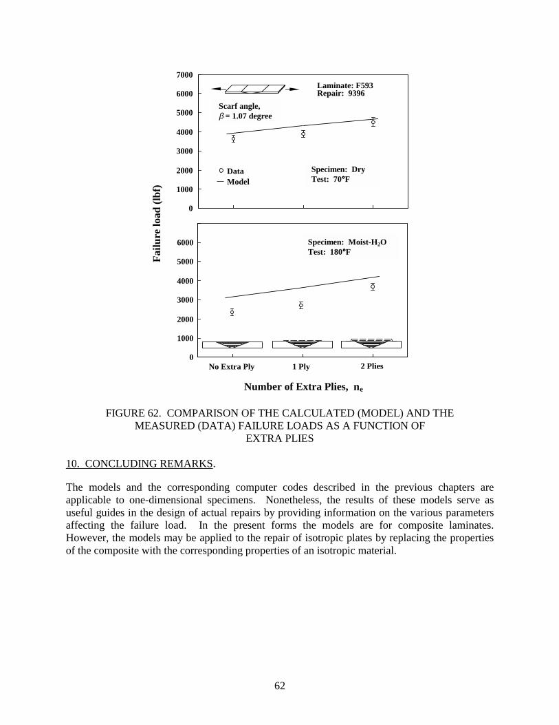
The failure loads calculated by the model are compared to the data in figures 59 through 62. The calculated and measured failure loads agree well, both for dry specimens tested at 70°F and for moisturized specimens tested at 180°F. These agreements lend support to the validities of the models, keeping in mind that the first failure prediction at each environment was used to obtain interlayer properties which were subsequently used for all other predictions. Thus, one can conclude that the trends are very well predicted by the model but not necessarily the absolute values of the failure load.
2000
4000
6000
8000
Fai
lure
Loa
d (l
bf)
2000
4000
6000
8000
2000
4000
6000
8000
01.0 2.0 3.0 4.0
Lap length, dl (in)
0.0 1.0 2.0 3.0 4.0
Laminate: F593Repair: 9396
DataModel
Specimen: DryTest: 70F
Specimen: Moist (H O)Test: 180 F
2
1 repair ply
2 repair plies
3 repair plies
dl
8[0]
FIGURE 59. COMPARISONS OF THE CALCULATED (MODEL) AND THE MEASURED (DATA) FAILURE LOADS AS A FUNCTION OF
LAP LENGTH FOR 8-PLY LAMINATE
61
2000
4000
6000
8000
2000
4000
6000
8000 0
2000
4000
6000
8000
1.0
2.0
3.0
4.0
Lap
leng
th, d
l (i
n)
0.0
1.0
2.0
3.0
4.0
1 re
pair
ply
2 re
pair
plie
s
3 re
pair
plie
s
Spec
imen
: D
ryT
est:
70F
Spec
imen
: M
oist
(H
O)
Tes
t: 1
80 F
2
Lam
inat
e: F
593
Rep
air:
939
6
Dat
aM
odel
d l
Failure Load (lbf)
[0] 32
0
1000
2000
3000
4000
5000
6000
Failure load (lbf)1
1.5
2
Scar
f Ang
le,β
(deg
ree)
0
1000
2000
3000
4000
5000
6000
7000
Spec
imen
: D
ryT
est:
70F
Dat
a
Mod
el
Spec
imen
:Moi
st-H
OT
est:
180
F2
Lam
inat
e: F
593
Rep
air:
939
6
tan(
β)=
H d sd s
H
FIG
UR
E 60
. C
OM
PAR
ISO
N O
F TH
E C
ALC
ULA
TED
(M
OD
EL) A
ND
TH
E M
EASU
RED
(DA
TA) F
AIL
UR
E
LOA
DS
AS
A F
UN
CTI
ON
OF
LAP
LEN
GTH
FO
R
32-P
LY L
AM
INA
TE
FIG
UR
E 61
. C
OM
PAR
ISO
NS
OF
THE
CA
LCU
LATE
D
(MO
DEL
) AN
D T
HE
MEA
SUR
ED (D
ATA
) FA
ILU
RE
LO
AD
S A
S A
FU
NC
TIO
N O
F SC
AR
F A
NG
LE

64
14. R. H. Stone, “Development of Repair Procedures for Graphite/Epoxy Structures on Commercial Transports,” Composite Repairs, SAMPE Monograph No. 1 (H. Brown, ed.), pp. 26-39, 1985.
15. J. F. Knauss and R. H. Stone, “Demonstration of Repairability and Repair Quality on
Graphite/Epoxy Structural Supplements,” Composite Repairs, SAMPE Monograph No. 1 (H. Brown, ed.), pp. 40-51, 1985.
16. R. H. Stone, “Field-Level Repair Materials and Processes,” Composite Repairs, SAMPE
Monograph No. 1 (H. Brown, ed.), pp. 87-99, 1985. 17. A. S. Falcone, “Field Repairs for the AH-1 Composite Main Rotor Blade,” Composite
Repairs, SAMPE Monograph No. 1 (H. Brown, ed.), pp. 100-109, 1985. 18. J. R. Scott and C. K. Mashiba, “Improved Resins for Wet Layup Repair of Advanced
Composite Structure,” Composite Repairs, SAMPE Monograph No. 1 (H. Brown, ed.), pp. 110-116, 1985.
19. J. Mahon and J. Candella, “Development of Large-Area Damage Repair Procedures for
the F-14A Horizontal Stabilizer, Phase I-Repair Development,” Composite Repairs, SAMPE Monograph No. 1 (H. Brown, ed.), pp. 184-194, 1985.
20. R. H. Stone, Repair Techniques for Graphite/Epoxy Structures for Commercial Transport
Applications. NASA Contractor Report, CR 159056, 1983. 21. Advanced Composite Repair Guide, Nor 82-60, Northrop Corporation, 1982. 22. S. H. Myhre and J. D. Labor, “Repair of Advanced Composite Structures,” Journal of
Aircraft, Vol. 18, pp. 546-552, 1980. 23. S. H. Myhre and R. W. Kiger, “Problems and Options in Advanced Composite Repair,”
Fibrous Composites in Structural Design, Plenum Press, pp. 359-380, 1981. 24. L. O. Bardygula, “CACRC: Progress and Plans,” Composites ’96 Manufacturing and
Tooling Conference, Society of Manufacturing Engineers, pp. 229-239, 1996. 25. P. Shyprykevich, C. S. Springer, and S. H. Ahn, “Standardization of Composite Repairs
for Commercial Transport Aircraft,” Composite Repair of Aircraft Structures Symposium, pp. 1-24, 1995.
26. S. H. Ahn, G. S. Springer, and P. Shyprykevich, “Composite Repair with Wet Lay-up and
Prepreg,” Composites ’96 Manufacturing and Tooling Conference, Society of Manufacturing Engineers, pp. 211-226, 1996.
65
27. L. J. Hart-Smith, R. W. Ochsner, and R. L. Radecky, “Surface Preparation of Composites for Adhesive-Bonded Repair,” Engineered Materials Handbook, ASM International, Vol. 3, pp. 840-844, 1987.
28. H. S. Kim, S. J. Lee, and D. G. Lee, “Development of a Strength Model for the Cocured
Stepped Lap Joints Under Tensile Loading,” Composite Structures, Vol. 32, pp. 593-600, 1995.
29. S. H. Myhre and C. E. Beck, “Repair Concepts for Advanced Composite Structures,”
Journal of Aircraft, Vol. 16, pp. 720-728, 1979. 30. W. S. Chan and C. T. Sun, “Interfacial Stresses and Strength of Lap Joints,” 21st
Conference of Structures, Structural Dynamics, and Materials, AIAA/ASME/ASCE/AHS, pp. 656-663, 1980.
31. S. J. John, A. J. Kinloch, and F. L. Matthews, “Measuring and Predicting the Durability
of Bonded Carbon Fiber/Epoxy Composite Joints,” Composites, Vol. 22, pp. 121-126, 1991.
32. J. E. Robson, F. L. Matthews, and A. J. Kinloch, “The Bonded Repair of Fibre
Composite: Effect of Composite Moisture Content,” Composite Science and Technology, Vol. 52, pp. 235-246, 1994.
33. B. M. Parker, “The Effect of Composite Prebond Moisture on Adhesive-Bonded CFRP-
CFRP Joints,” Composites, Vol. 14, pp. 226-232, 1983. 34. S. H. Mylire, J. D. Labor, and S. C. Aker, “Moisture Problems in Advanced Composite
Structural Repair,” Composites, Vol. 13, pp. 289-299, 1982. 35. O. Volkersen, “Die Nietkraftverteilung in Zugbeanspruchten Nietverbindungen mit
Konstanten Laschenquerschnitten,” Luftfahrtforschung, Vol. 15, pp. 41-47, 1938. 36. M. Goland and E. Reissner, “The Stresses in Cemented Joints,” Journal of Applied
Mechanics, Vol.11, pp. A17-A27, 1944. 37. J. Pirvics, “Two Dimensional Displacement-Stress Distributions in Adhesive Bonded
Composite Structures,” Journal of Adhesion, Vol. 6, pp. 207-228, 1974. 38. D. J. Aliman, “A Theory for Elastic Stresses in Adhesive Bonded Lap Joints,” Quarterly
Journal of Applied Mathematics, Vol. XXX, Pt. 4, pp. 415-436, 1977. 39. I. U. Ojalvo and H. L. Eidinoff, “Bond Thickness Effects Upon Stresses in Single-Lap
Adhesive Joints,” AIAA Journal, Vol. 16, pp. 204-211, 1978. 40. W. J. Renton and J. R. Vinson, “The Efficient Design of Adhesive Bonded Joints,”
Journal of Adhesion, Vol.7, pp.175-193, 1975.
66
41. F. Thamm, “Stress Distribution in Lap Joints With Partially Thinned Adherends,” Journal of Adhesion, Vol. 7, pp. 301-309, 1976.
42. G. R. Wooley and D. R. Carver, “Stress Concentration Factors for Bonded Lap Joints,”
Journal of Aircraft, Vol. 8, pp. 817-820, 1971. 43. R. D. Adams and N. A. Peppiatt, “Stress Analysis of Adhesive-Bonded Lap Joints,”
Journal of Strain Analysis, Vol. 9, pp. 185-196, 1974. 44. D. A. Bigwood and A. D. Crocombe, “Elastic Analysis and Engineering Design
Formulae for Bonded Joints,” International Journal of Adhesion and Adhesives, Vol. 9, pp. 229-242, 1989.
45. D. A. Bigwood and A. D. Crocombe, “Nonlinear Adhesive Bonded Joints Design
Analyses,” International Journal of Adhesion and Adhesives, Vol. 10, pp. 31-41, 1990. 46. A. D. Crocombe, “Global Yielding as a Failure Criterion for Bonded Joints,”
International Journal of Adhesion and Adhesives, Vol. 9, pp. 145-153, 1989. 47. F. Szépe, “Strength of Adhesive-Bonded Lap Joints With Respect to Change of
Temperature and Fatigue,” Experimental Mechanics, Vol. 6, pp. 280-286, 1966. 48. R. D. Adams, J. Coppendale, and N. A. Peppiatt, “Failure Analysis of Aluminuium-
Aluminuium Bonded Joints,” Adhesion 2 (K. W. Allen, ed.), Applied Science Publisher, pp. 105-120, 1978.
49. J. L. Lubkin, “A Theory of Adhesive Scarf Joints,” Journal of Applied Mechanics,
Vol. 24, pp. 255-260, 1957. 50. W. J. Renton and J. R. Vinson, “On The Behavior of Bonded Joints in Composite
Material Structures,” Engineering Fracture Mechanics, Vol. 7, pp. 41-60, 1975. 51. W. J. Renton and J. R. Vinson, “Analysis of Adhesively Bonded Joints Between Panels
of Composite Materials,” Journal of Applied Mechanics, Vol. 44, pp. 101-106, 1977. 52. R. M. Baker and F. Hatt, “Analysis of Bonded Joints in Vehicular Structures,” AIAA
Journal, Vol. 11, pp. 1650-1654, 1973. 53. G. C. Grimes, “Stress Distribution in Adhesive Bonded Lap Joints,” SAE Trans. 710107,
pp. 370-378, 1971. 54. F. Erdogan and M. Ratwani, “Stress Distribution in Bonded Joints,” Journal of
Composite Materials, Vol. 5, pp. 379-393, 1971. 55. C. L. Johnson, “Effect of Ply Staking Sequence on Stress in a Scarf Joint,” AIAA Journal,
Vol. 27, pp. 79-86, 1989.
67/68
56. L. J. Hart-Smith, Adhesive-Bonded Single-Lap Joints. NASA Contract Report, CR 112236,1973.
57. L. J. Hart-Smith, Adhesive-Bonded Double-Lap Joints. NASA Contract Report,
CR 112235, 1973. 58. L. J. Hart-Smith, Non-Classical Adhesive-Bonded Joints in Practical Aerospace
Construction, NASA Contract Report, CR 112238,1973. 59. L. J. Hart-Smith, “Further Developments in the Design and Analysis of Adhesive-Bonded
Structural Joints,” Joining of Composite Materials, ASTM STP 749 (K. T. Kedward, ed.), American Society for Testing and Materials, pp. 3-31, 1981.
60. R. D. Adams, R. W. Atkins, J. A. Harris, and A. J. Kinloch, “Stress Analysis and Failure
Properties of Carbon-Fiber-Reinforced-Plastic/Steel Double-Lap Joints,” Journal of Adhesion, Vol. 20, pp. 29-53, 1986.
61. R. D. Adams, “Theoretical Stress Analysis of Adhesively Bonded Joints,” Joining Fibre-
Reinforced Plastics, (F. L. Matthews, ed.), Elsevier Applied Science Publisher, pp. 185-226, 1987.
62. L. J. Hart-Smith, Adhesive-Bonded Scarf and Stepped-Lap Joints, NASA Contract
Report, CR 112237, 1973. 63. S. W. Tsai and H. T. Hahn, Introduction to Composite Materials, Technomic Publishing
Company, 1980. 64. T. H. G. Megson, Aircraft Structures for Engineering Students, 2nd ed., Halsted Press,
pp. 405-406, 1990. 65. N. J. Naik, Woven Fabric Composites, Technomic Publishing Co., 1994.
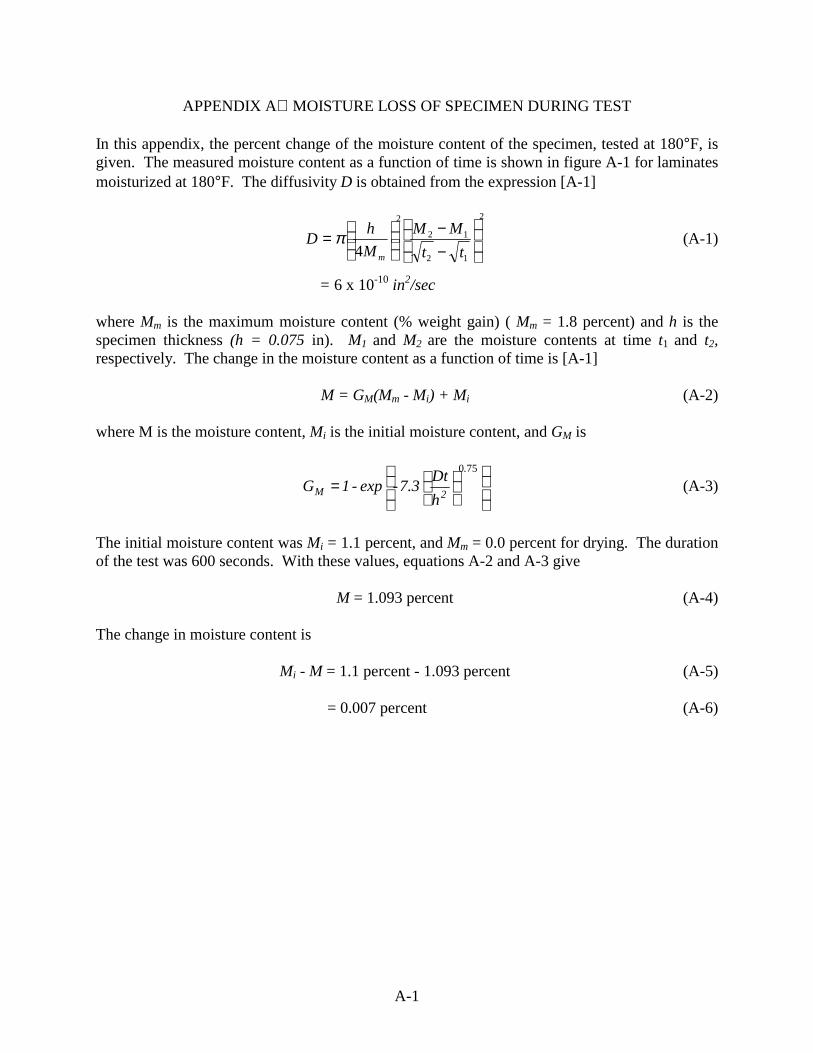
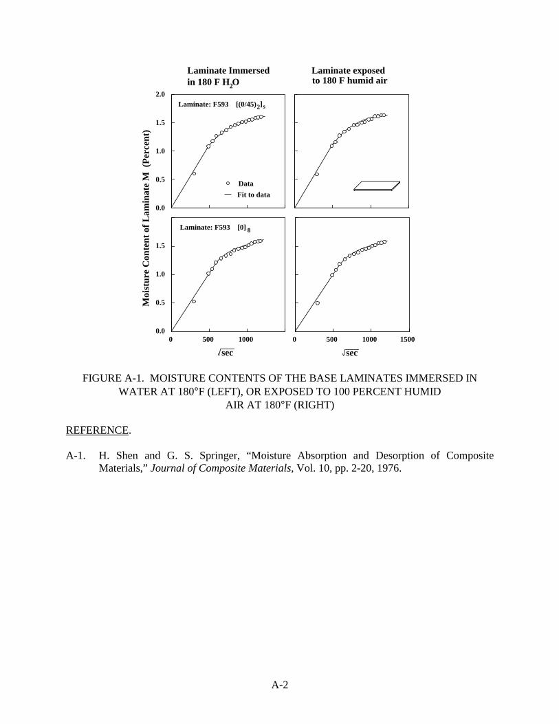
A-2
0.0
0.5
1.0
1.5
2.0
Moi
stur
e C
onte
nt o
f L
amin
ate
M (
Per
cent
)
0.0
0.5
1.0
1.5
0 500 1000
sec
0 500 1000 1500
in 180 F H O
Data
Fit to data
to 180 F humid air
Laminate: F593 [0] 8
Laminate: F593 [(0/45) ]2
Laminate Immersed
2
Laminate exposed
sec
s
FIGURE A-1. MOISTURE CONTENTS OF THE BASE LAMINATES IMMERSED IN WATER AT 180°F (LEFT), OR EXPOSED TO 100 PERCENT HUMID
AIR AT 180°F (RIGHT) REFERENCE. A-1. H. Shen and G. S. Springer, “Moisture Absorption and Desorption of Composite
Materials,” Journal of Composite Materials, Vol. 10, pp. 2-20, 1976.
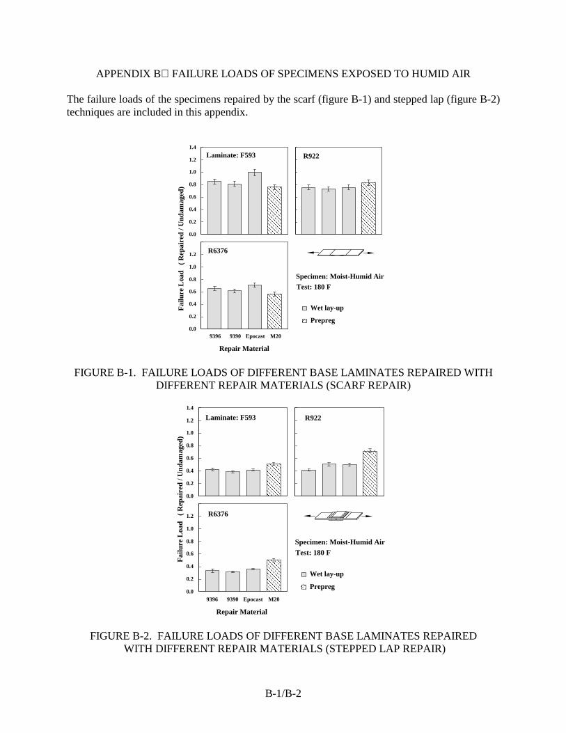
B-1/B-2
APPENDIX B FAILURE LOADS OF SPECIMENS EXPOSED TO HUMID AIR The failure loads of the specimens repaired by the scarf (figure B-1) and stepped lap (figure B-2) techniques are included in this appendix.
0.0
0.2
0.4
0.6
0.8
1.0
1.2
1.4
0.0
0.2
0.4
0.6
0.8
1.0
1.2
Fai
lure
Loa
d (
Rep
aire
d / U
ndam
aged
)
Prepreg
Wet lay-up
R922Laminate: F593
R6376
Specimen: Moist-Humid Air
Test: 180 F
9396 9390 Epocast M20
Repair Material
FIGURE B-1. FAILURE LOADS OF DIFFERENT BASE LAMINATES REPAIRED WITH DIFFERENT REPAIR MATERIALS (SCARF REPAIR)
0.0
0.2
0.4
0.6
0.8
1.0
1.2
1.4
0.0
0.2
0.4
0.6
0.8
1.0
1.2
Fai
lure
Loa
d (
Rep
aire
d / U
ndam
aged
)
R6376
Laminate: F593 R922
9396 9390 Epocast M20
Repair Material
Prepreg
Wet lay-up
Specimen: Moist-Humid Air
Test: 180 F
FIGURE B-2. FAILURE LOADS OF DIFFERENT BASE LAMINATES REPAIRED WITH DIFFERENT REPAIR MATERIALS (STEPPED LAP REPAIR)
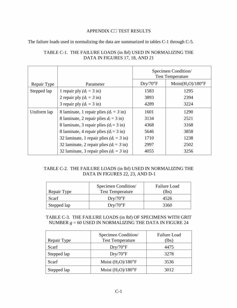
C-1
APPENDIX C TEST RESULTS The failure loads used in normalizing the data are summarized in tables C-1 through C-5.
TABLE C-1. THE FAILURE LOADS (in lbf) USED IN NORMALIZING THE DATA IN FIGURES 17, 18, AND 21
Specimen Condition/ Test Temperature
Repair Type
Parameter Dry/70°F Moist(H2O)/180°F Stepped lap 1 repair ply (dl = 3 in) 1583 1295 2 repair ply (dl = 3 in) 3893 2394 3 repair ply (dl = 3 in) 4289 3224
Uniform lap 8 laminate, 1 repair plies (dl = 3 in) 1601 1290 8 laminate, 2 repair plies dl = 3 in) 3134 2521 8 laminate, 3 repair plies (dl = 3 in) 4368 3168 8 laminate, 4 repair plies (dl = 3 in) 5646 3858 32 laminate, 1 repair plies (dl = 3 in) 1710 1238 32 laminate, 2 repair plies (dl = 3 in) 2997 2502 32 laminate, 3 repair plies (dl = 3 in) 4055 3256
TABLE C-2. THE FAILURE LOADS (in lbf) USED IN NORMALIZING THE DATA IN FIGURES 22, 23, AND D-1
Repair Type
Specimen Condition/ Test Temperature
Failure Load (lbs)
Scarf Dry/70°F 4526 Stepped lap Dry/70°F 3360
TABLE C-3. THE FAILURE LOADS (in lbf) OF SPECIMENS WITH GRIT
NUMBER g = 60 USED IN NORMALIZING THE DATA IN FIGURE 24
Repair Type
Specimen Condition/ Test Temperature
Failure Load (lbs)
Scarf Dry/70°F 4475 Stepped lap Dry/70°F 3278
Scarf Moist (H2O)/180°F 3536
Stepped lap Moist (H2O)/180°F 3012
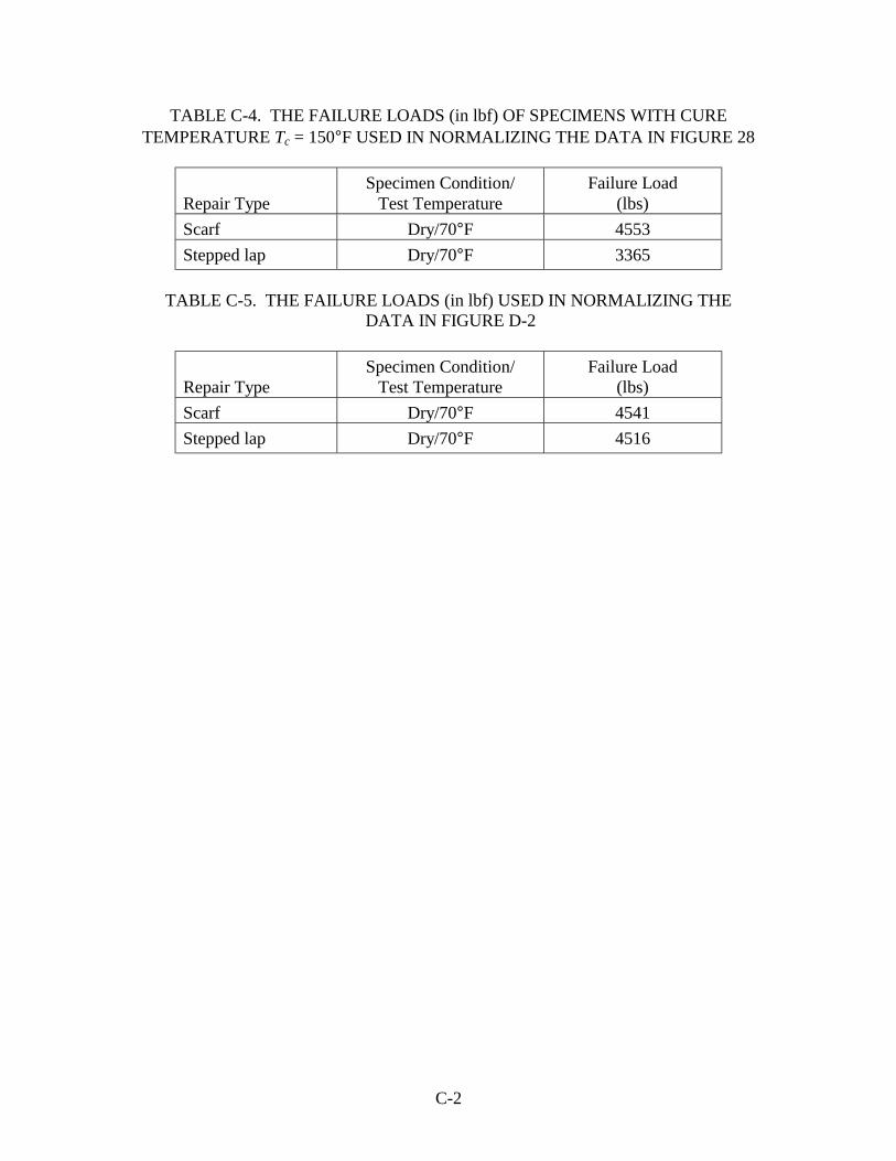
C-2
TABLE C-4. THE FAILURE LOADS (in lbf) OF SPECIMENS WITH CURE TEMPERATURE Tc = 150°F USED IN NORMALIZING THE DATA IN FIGURE 28
Repair Type
Specimen Condition/ Test Temperature
Failure Load (lbs)
Scarf Dry/70°F 4553 Stepped lap Dry/70°F 3365
TABLE C-5. THE FAILURE LOADS (in lbf) USED IN NORMALIZING THE
DATA IN FIGURE D-2
Repair Type
Specimen Condition/ Test Temperature
Failure Load (lbs)
Scarf Dry/70°F 4541 Stepped lap Dry/70°F 4516
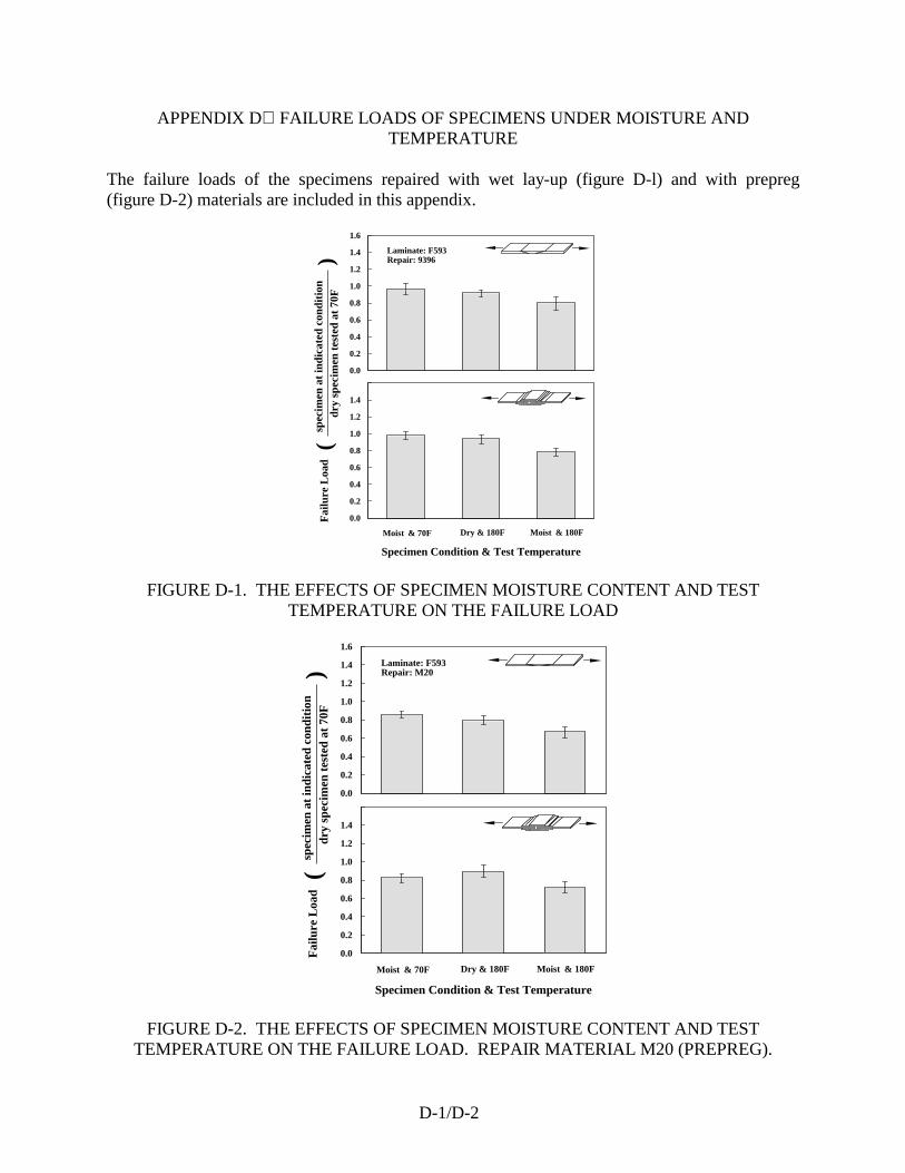
D-1/D-2
APPENDIX D FAILURE LOADS OF SPECIMENS UNDER MOISTURE AND TEMPERATURE
The failure loads of the specimens repaired with wet lay-up (figure D-l) and with prepreg (figure D-2) materials are included in this appendix.
Dry & 180FMoist & 70F Moist & 180F
Specimen Condition & Test Temperature
spec
imen
at
indi
cate
d co
ndit
ion
dry
spe
cim
en t
este
d at
70F
)
0.0
0.2
0.4
0.6
0.8
1.0
1.2
1.4
1.6
Laminate: F593Repair: 9396
0.0
0.2
0.4
0.6
0.8
1.0
1.2
1.4
(F
ailu
re L
oad
FIGURE D-1. THE EFFECTS OF SPECIMEN MOISTURE CONTENT AND TEST TEMPERATURE ON THE FAILURE LOAD
Dry & 180FMoist & 70F Moist & 180F
Specimen Condition & Test Temperature
spec
imen
at
indi
cate
d co
ndit
ion
dry
spe
cim
en t
este
d at
70F
)
0.0
0.2
0.4
0.6
0.8
1.0
1.2
1.4
1.6
Laminate: F593Repair: M20
0.0
0.2
0.4
0.6
0.8
1.0
1.2
1.4
(F
ailu
re L
oad
FIGURE D-2. THE EFFECTS OF SPECIMEN MOISTURE CONTENT AND TEST TEMPERATURE ON THE FAILURE LOAD. REPAIR MATERIAL M20 (PREPREG).