Embed Size (px)
Citation preview

03.06 Andreas Hettich GmbH & Co. KG AR1004EN
Repair instructions
EBA 21

2/42
Andreas Hettich GmbH & Co. KG Föhrenstraße 12, D-78532 Tuttlingen / Germany Phone (07461) 705-0 Fax (07461) 705-125 [email protected], [email protected] www.hettichlab.com
© 2003 by Andreas Hettich GmbH & Co. KG
All rights reserved. No part of this publication may be reproduced without the written prior permission of the copyright owner.
Modifications reserved!
AR1004EN / 03.06

3/42
Contents 1 Introduction ..............................................................................................................5
2 Symbol meanings.....................................................................................................5
3 Description of the centrifuge.....................................................................................6
3.1 Control panel (A4) .............................................................................................6
3.2 Supply board (A1) .............................................................................................6
3.3 Frequency converter (A2) .................................................................................7
3.4 Special features ................................................................................................8
3.5 Brake resistor (R1) ............................................................................................8
3.6 Motor / tacho system.........................................................................................8
3.7 Lid lock..............................................................................................................8
3.8 Imbalance switch...............................................................................................9
3.9 Safety devices...................................................................................................9
4 Troubleshooting procedures.....................................................................................9
5 Error messages......................................................................................................10
5.1 MAINS RESET................................................................................................10
5.2 Brief description ..............................................................................................10
5.3 Description and elimination of errors...............................................................12
6 Settings and interrogations.....................................................................................21
6.1 Initialization .....................................................................................................21
6.1.1 Prerequisites for the initialization .............................................................21
6.1.2 Initializing the centrifuge ..........................................................................22
6.2 Imbalance Mode..............................................................................................23
6.3 Parameter interrogation ..................................................................................23
6.4 Acoustic Signal................................................................................................23
6.5 Working hours .................................................................................................24
6.6 Checking the motor slippage...........................................................................24
6.7 Setting the display contrast .............................................................................25
6.8 Imbalance switch-off .......................................................................................25
7 Change mains input fuse........................................................................................26
8 Functional check after a repair ...............................................................................26
9 General arrangement of the components...............................................................27

4/42
10 Mounting and removing components ................................................................. 29
10.1 Removing the centrifuge chamber .................................................................. 29
11 Short the mains choke coil (L1) .......................................................................... 30
12 Technical documents ......................................................................................... 31
12.1 Tachometer code configuration of the rotors .................................................. 31
12.2 Circuit diagrams.............................................................................................. 32
12.2.1 Abbreviations of the cable colours........................................................... 32
12.2.2 Mains supply with supply board (A1) 230 V............................................. 33
12.2.3 Mains supply with supply board (A1) 115 V............................................. 34
12.2.4 Circuit diagram supply board (A1) ........................................................... 35
12.2.5 Connecting- and component diagram supply board (A1) ........................ 36
12.2.6 Signals in the flat ribbon cable between control panel (A4) and supply board (A1)................................................................................................ 37
12.2.7 Block diagram control panel (A4)............................................................. 38
12.2.8 Connecting diagram control panel (A4) ................................................... 39
12.2.9 Block diagram frequency converter (A2) and signals in flat ribbon cable between frequency converter (A2) and supply board (A1) ...................... 40
12.2.10 Connecting diagram frequency converter (A2)..................................... 41
12.3 Technical specifications.................................................................................. 42
5/42
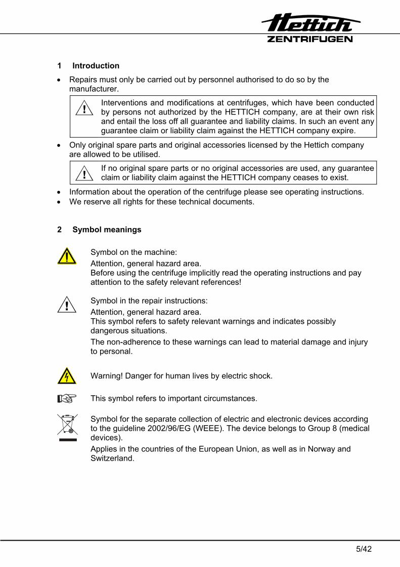
1 Introduction • Repairs must only be carried out by personnel authorised to do so by the
manufacturer.
Interventions and modifications at centrifuges, which have been conducted by persons not authorized by the HETTICH company, are at their own risk and entail the loss off all guarantee and liability claims. In such an event any guarantee claim or liability claim against the HETTICH company expire.
• Only original spare parts and original accessories licensed by the Hettich company are allowed to be utilised.
If no original spare parts or no original accessories are used, any guarantee claim or liability claim against the HETTICH company ceases to exist.
• Information about the operation of the centrifuge please see operating instructions. • We reserve all rights for these technical documents. 2 Symbol meanings
Symbol on the machine: Attention, general hazard area. Before using the centrifuge implicitly read the operating instructions and pay attention to the safety relevant references!
Symbol in the repair instructions: Attention, general hazard area. This symbol refers to safety relevant warnings and indicates possibly dangerous situations. The non-adherence to these warnings can lead to material damage and injury to personal.
Warning! Danger for human lives by electric shock.
This symbol refers to important circumstances.
Symbol for the separate collection of electric and electronic devices according to the guideline 2002/96/EG (WEEE). The device belongs to Group 8 (medical devices). Applies in the countries of the European Union, as well as in Norway and Switzerland.

6/42
3 Description of the centrifuge These microprocessor controlled centrifuges mainly consist of the following electrical components: • Control panel, microprocessor controlled • Supply board • Frequency converter with braking chopper (motor control), microprocessor controlled • Motor with speed sensor (speedometer) and imbalance switch • Brake resistor • Lid lock 3.1 Control panel (A4) The control panel is the brain or the master of the centrifuge. This MASTER controls its SLAVE via a serial data bus system. This SLAVE is the following component:
− frequency converter The control panel carries out the following tasks: • Managing operator entries and controlling the LCD display • Saving of 3 run programs • Controlling the components:
− frequency converter via the release line and the serial interface • Evaluating the speed sensor (speedometer) • Evaluating the imbalance switch • Evaluating the frequency converter error message line • Evaluating the message line lid lock open/closed • Triggering the relay for the lid lock solenoid when the rotor has standstill • Type of serial interface:
− 5 Volt interface with three wires (16-pole flat ribbon cable, pole 6, 8 and 11) • The voltage supply for the control panel is provided by the supply board via the flat
ribbon cable: + 10...15 Volt pole 1, 2 GND pole 15, 16 3.2 Supply board (A1) The supply board carries out the following tasks: • Current supply 12 V DC and 5 V DC for the supply board • Current supply 12 V DC for the control panel • Slot X5 for message line lid lock open/closed. Transmission of the signal to the
control panel via opto-coupler. • Voltage supply for the speed sensor (speedometer) • Slot for speed sensor cable and transmission of the speed pulses to the control
panel and to the frequency converter • Triggering the relay for the lid lock solenoid when the rotor has standstill • Slot for imbalance switch and direct transmission of the imbalance signal to the
control panel

7/42
• The 5 Volt interface with three wires is transferred to a RS 485 interface with two wires. Interface for the frequency converter: RS 485 interface via two wires
• Transmitting the main enable signal (= Hardware STOP) control panel ⇒ frequency converter
• Transmitting the error line (= FC-ERROR) frequency converter ⇒ control panel 3.3 Frequency converter (A2) The frequency converter carries out the following tasks: • Generating the motor current supply
(three-phase current with variable frequency and voltage) Functional description: The supply voltage is rectified, smoothened and
chopped into a pulse width pattern in three bridge elements with a microprocessor.
• Monitoring the motor current • Evaluating the overtemperature switch in the motor (only 115V version) • The braking chopper transfers the electrical energy produced during braking, in the
230 V version from a voltage of approx. 390 Volt and in the 115 V version from a voltage of approx. 200 Volt, to the brake resistor in a controlled manner.
• SLAVE behaviour (the requests and commands of the control panel are transmitted via the serial interface): RS 485 Volt interface with two wires (10-pole flat ribbon cable, pole 3 and 5)
• Evaluating the main enable signal (= Hardware STOP) for the frequency converter (10-pole flat ribbon cable, pole 7)
• Evaluating possible errors and handling the error line (= FC-ERROR) (10-pole flat ribbon cable, pole 4)
• The following are defined by the control panel via the serial interface: − Speed − Starting and brake levels − Control commands START, BRAKE, STOP
• LED status displays: In the standby status the green LED illuminates In the run status the green LED illuminates In the error status the green LED flashes
If the frequency converter processor detects an error, it switches off automatically and sets the error line (FC-ERROR). Then the control panel inquires the type of error via the serial interface.

8/42
3.4 Special features • Multiprocessor concept:
If a processor stops working, the other processor still continue monitoring its area. If there is a control panel failure, the frequency converter automatically switches off the drive if no inquiries are made via the interface for longer than 60 seconds.
• Interface concept: The information transmission is monitored with an additional check sum.
• Hardware concept: All safety related switches are break contacts. This also ensures that loose contacts and cable rupture can be detected.
3.5 Brake resistor (R1) • An overtemperature fuse protects the brake resistor against fire. If the braking
chopper has a short circuit, the brake resistor becomes hot due to the high current, and the overtemperature fuse cuts off the frequency converter from the mains supply.
3.6 Motor / tacho system • The motor is a three-phase asynchronous motor with two pairs of poles. • A speed sensor (speedometer) which is screwed onto the motor receives
− the rotor code information and − the speed information (6 pulses per revolution) from the magnets of the tacho ring attached to the rotor.
• The control panel monitors and regulates the ACTUAL speed.
− Double safety: In addition, the frequency converter has been programmed in such a way that it is not possible to set a speed value which is higher than the permissible rotor speed. The frequency converter monitors the speed and switches off the drive at excess speed (error message "ERROR 84").
• The control panel monitors the rotor standstill. − The lid can only be opened when the control panel has detected standstill.
3.7 Lid lock • Opening of the lid lock is prevented by a latch. The lid lock can only be opened when
the relay on the supply board is energized by the control panel. This occurs when the rotor is at standstill and mains power is applied. A solenoid is energized and releases the latch.
• The centrifuge can only be started when the lid is closed. A microswitch on the lid lock detects the position of the lid lock.
9/42
3.8 Imbalance switch • A switch (break contact) detects imbalance. • Imbalance is detected only in running mode (starting, centrifuging and braking). • If imbalance is detected, the drive is brought to a standstill. 3.9 Safety devices Mains input ⇒ Mains fuses Radio interference suppression filter
⇒ between supply board and frequency converter
Frequency converter ⇒ electronically protected Motor ⇒ overtemperature switch > 135 °C 4 Troubleshooting procedures • Fuses in installation in which centrifuge is installed are intact. • Mains input fuses of centrifuge are intact. • Supply voltage present at (see circuit diagram):
− Connecting cable − Appliance plug − Mains switch − Supply board, plug X5 (pin 1, pin 5)
• Look for the displayed error code in the chapter "Error messages". • Remedy the error according to the instructions. • Carry out a functional check after every repair and whenever a component is
replaced, see chapter "Functional check after a repair".

10/42
5 Error messages 5.1 MAINS RESET • Switch off the mains switch. • Wait for 10 seconds and then switch on the mains switch again. 5.2 Brief description
Error designation No. Brief description Page
TACHO-ERROR 01 Speedometer pulses break down during rotation 12 TACHO-ERROR 02 No speedometer pulses after start command 12
IMBALANCE (03)* Imbalance on motor axle 13 CONTROL-ERROR 04 Lid lock error, lid opened without recognizing that
motor had stopped 13
N > MAX 05 Excessive speed error, 250 RPM above n-max of rotor
14
ROTORCODE 10 Invalid rotor code 14 MAINS INTERRUPT (11)* Mains interruption 14 VERSION-ERROR 12 Error in initialization 15
N < MIN 13 Speed error, slippage is too great 15 CONTROL-ERROR 21 Control panel – error: speed 15 CONTROL-ERROR 22 Control panel – error: I²C bus 15 CONTROL-ERROR 23 Control panel – error: display memory 15 CONTROL-ERROR 24 Control panel – error: clock timeout 15 CONTROL-ERROR 25 Control panel – error: EEPROM 15 CONTROL-ERROR 26 Control panel – error: driver defective 15 N > ROTOR-MAX --- Control panel – error: nominal speed is higher
than permitted rotor speed or nominal RCF is higher than permitted rotor RCF
16
* Error number will not be displayed

11/42
Error designation No. Brief description Page
SER I/O-ERROR 30 No connection between control panel and serial interface
16
SER I/O-ERROR 31 No connection between frequency converter and serial interface
16
SER I/O-ERROR 33 Data incorrectly transmitted from the componentry
16
SER I/O-ERROR 34 Data incorrectly transmitted between control panel and frequency converter
17
SER I/O-ERROR 36 No acknowledgement (NAK) from frequency converter to control panel
17
FU/CCI-ERROR 60 Faulty release signal to frequency converter 17 FU/CCI-ERROR 61 Frequency converter - error: computing section 18 FU/CCI-ERROR 62 Frequency converter - error: undervoltage 18 FU/CCI-ERROR 63 Frequency converter - error: overcurrent 18 FU/CCI-ERROR 64 Frequency converter - error: overvoltage 19 FU/CCI-ERROR 67 Frequency converter - error: overtemperature in
motor (only 115V) 19
FU/CCI-ERROR 68 Frequency converter - error: overtemperature in frequency converter
19
FU/CCI-ERROR 69 Frequency converter - error: EEPROM 19 FU/CCI-ERROR 84 Frequency converter - error: Frequency con
verter recognizes excess speed
20
FU/CCI-ERROR 85 Frequency converter - error: “Watchdog” in frequency converter had triggered
20

12/42
5.3 Description and elimination of errors TACHO - ERROR 01
Error During centrifugation the speedometer pulses are interrupted. Error
consequence The rotor slows down until it stops. After the rotor stops, there is a DC braking for 30 sec. An MAINS RESET during slowing-down causes a DC braking for 3 min. After the DC braking, the ”open the lid” release takes place.
Cause of error / measurements
• Speed sensor (speedometer) defective or loose contact on plug. Measure speedometer pulses on plug X4 / supply board (pin 4 - pin 2).
• Flat ribbon cable to control panel, or flat ribbon cable to frequency converter is defective. Measure speedometer pulses on control panel / plug X1 (pin 14) and on frequency converter / plug S501 (pin 8).
• Supply board or control panel or frequency converter is defective.
Error code reset Open the lid. Turn the rotor by hand and perform a MAINS RESET while the rotor is turning.
TACHO - ERROR 02
Error There are no speedometer pulses on the control panel after start-up.
Error consequence
The rotor slows down until it stops. After the rotor stops, there is a DC braking for 30 sec. An MAINS RESET during slowing-down causes a DC braking for 3 min. After the DC braking, the ”open the lid” release takes place.
Cause of error / measurements
• Start-up took place without the rotor. • Motor not connected. • Motor is defective. • Speed sensor (speedometer) defective, or loose contact on
plug. Measure speedometer pulses on plug X4 / supply board (pin 4 - pin 2).
• Flat ribbon cable to control panel, or flat ribbon cable to frequency converter is defective. Measure speedometer pulses on control panel / plug X1 (pin 14) and on frequency converter / plug S501 (pin 8).
• No release signal to frequency converter. • Supply board or control panel or frequency converter is
defective. Error code reset Open the lid. Turn the rotor by hand and perform a MAINS
RESET while the rotor is turning.

13/42
IMBALANCE
Error Imbalance on motor axle. Error
consequence The centrifuge slows down until the “open the lid” release occurs.
Cause of error / measurements
• Weight difference in rotor components. • Supporting lugs not lubricated. • False IMBALANCE MODE is set (see chapter "Imbalance
Mode"). • Imbalance switch not connected. • Imbalance switch is defective.
Measure on supply board / plug X3 (pin 4), see chapter "Mains supply with supply board (A1)".
• Loose contact in cable or plug. • Flat ribbon cable to control panel is defective.
Measure on control panel / plug X1 (pin 12) • control panel or supply board is defective.
Error code reset Open the lid or perform a MAINS RESET. CONTROL - ERROR 04
Error Lid lock is open during centrifugation. Error
consequence Slowing down until the ”open the lid” release occurs.
Cause of error • Lid lock is defective and can be opened during centrifugation.
• Loose contact in cable or in plug. • Flat ribbon cable to control panel is defective. • Control panel or supply board is defective.
Measurement Measure on supply board / plug X5 (pin 6) and on control panel / plug X1 (pin 5).
Error code reset Perform a MAINS RESET.

14/42
N > MAX 05
Error Excess speed. The speed recognised by the speed sensor (speedometer) is 250 RPM greater than the n-max speed of the rotor.
Error consequence
The centrifuge slows down until the ”open the lid” release occurs.
Cause of error • Insulation of speed sensor (speedometer) cable is defective.
• Loose contact on speed sensor (speedometer) cable. • Speed sensor (speedometer) is defective. • Flat ribbon cable to control panel is defective. • Control panel or frequency converter or supply board is
defective. Error code reset Perform a MAINS RESET.
ROTORCODE 10
Error An invalid rotor code was read during start-up. Error
consequence The centrifuge slows down until the ”open the lid” release occurs.
Cause of error • Magnetic coding on rotor is defective. • Speedometer system is defective. • Loose contact on speed sensor (speedometer) plug • Motor is rotating in the wrong direction.
Error code reset Open the lid or perform a MAINS RESET. MAINS INTERRUPT
Error Interruption of mains supply during centrifugation. Error
consequence The centrifuge slows down until the ”open the lid” release occurs.
− Switching on at the mains during centrifugation causes slowing-down until the ”open the lid” release occurs.
− Switching on at the mains when the rotor has stopped brings about the ”open the lid” release.
Cause of error • Power supply has failed. • Loose contact in electrical connections. • Flat ribbon cable to control panel is defective.
Error code reset Open the lid and press the START key.
This error cannot be reset by a MAINS RESET

15/42
VERSION - ERROR 12
Error Differences in the initialization from control panel (EPROM) or frequency converter.
Error consequence
No further user operation is possible.
Cause of error • An incorrect EPROM has been plugged into control panel. • Centrifuge is not initialised. Carry out an initialization, see
chapter "Initialization". Error code reset Perform a MAINS RESET.
N < MIN 13
Error Insufficient speed, motor slippage is too large. The centrifuge control can readjust the speed by max. 5 % (control limit). This error is displayed if the rotor speed (ACTUAL speed) is lower than the SET speed - 5%.
Error consequence
The centrifuge slows down until the ”open the lid” release occurs.
Cause of error • Motor is labouring (damage to bearings). • Motor has a short-circuited coil (coil is defective). • Loose contact in the electrical connections. • Frequency converter is defective. • Release signal to frequency converter was interrupted
during centrifugation. Error code reset Open the lid and perform a MAINS RESET.
CONTROL - ERROR 21 - 26
Error Internal error in control panel. Error
consequence The centrifuge slows down until the ”open the lid” release occurs.
Cause of error • Control panel is defective. Error code reset Perform a MAINS RESET.

16/42
N > ROTOR-MAX
Error Error in the entered program Error
consequence Further operation is not possible.
Cause of error SET speed or SET RCF is higher than the permissible rotor speed or permissible rotor RCF.
Error code reset Carry out a MAINS RESET or open the lid. Reduce the speed or RCF in the entered program to the permissible rotor speed or permissible rotor RCF.
SER I/O - ERROR 30 and ERROR 31
Error Control panel has no connection to the component frequency converter via serial interface.
Error consequence
The centrifuge slows down until the ”open the lid” release occurs.
Cause of error • Plug S501 on the frequency converter is not plugged. • Flat ribbon cable to frequency converter is defective. • There is no voltage on frequency converter. • Cables on connector S102 are not or wrong plugged. • overtemperature fuse on brake resistor has blown or is not
connected. • Control panel or frequency converter is defective.
Error code reset Perform a MAINS RESET. SER I/O - ERROR 33
Error Control panel is not receiving correct data from frequency converter.
Error consequence
The centrifuge slows down until the ”open the lid” release occurs.
Cause of error • Flat ribbon cable to frequency converter is defective. • Control panel or frequency converter is defective.
Error code reset Perform a MAINS RESET.

17/42
SER I/O - ERROR 34
Error Control panel is not receiving correct data from frequency converter.
Error consequence
The centrifuge slows down until the ”open the lid” release occurs.
Cause of error • Flat ribbon cable to frequency converter is defective. • Control panel or frequency converter is defective.
Error code reset Perform a MAINS RESET. SER I/O - ERROR 36
Error Frequency converter sends signal NAK to the control panel after receiving an unknown command. NAK (not acknowledged).
Error consequence
The centrifuge slows down until the ”open the lid” release occurs.
Cause of error • Flat ribbon cable to frequency converter is defective. • Frequency converter is defective. • Control panel is defective.
Error code reset Perform a MAINS RESET. FU / CCI - ERROR 60
Error The release signal was not correctly transmitted to frequency converter. The evaluation of the release signal only occurs once after MAINS RESET.
Error consequence
No further user operation is possible.
Cause of error • Flat ribbon cable to frequency converter is defective. • Flat ribbon cable to control panel is defective. • Supply board is defective.
Measurement Also see at control panel –X1 (PIN 4) and frequency converter -S501 (PIN 7).

18/42
General Notice for FU / CCI - ERROR 61 to FU / CCI - ERROR 69
Error consequence
• Frequency converter switches independently. • The rotor freewheels, coasting. • No further user operation is possible.
Error code reset • Mains switch is OFF. Switch mains switch to ON after 1 min.
Measurement • Also see at frequency converter -X501 (PIN 4) and control panel –X1 (PIN 13).
FU / CCI - ERROR 61
Error Error in computing section. Cause of error • Flat ribbon cable is defective.
• Frequency converter is defective. FU / CCI - ERROR 62
Error Undervoltage. Mains voltage less than 20% as nominal voltage.
Cause of error • Supply voltage too low, see chapter "Short the mains choke coil (L1)".
• Flat ribbon cable is defective. • Frequency converter is defective.
Measurement Also see at frequency converter, UDC. FU / CCI - ERROR 63
Error Overcurrent. Cause of error • Short circuit in motor.
• Motor impedance is too low. • Flat ribbon cable is defective. • Frequency converter is defective.

19/42
FU / CCI - ERROR 64
Error Voltage in intermediate circuit: >410 V DC at 230 V >205 V DC at 115 V This error normally only occurs when the drive is being braked.
Cause of error • Brake resistor is defective. • Flat ribbon cable is defective. • Frequency converter is defective.
Measurement Also see at frequency converter, UDC. FU / CCI - ERROR 67
Error Only centrifuges with 115 V. Overtemperature in the motor. The cable “overtemperature” in the motor has high impedance.
Cause of error • Overtemperature switch opens because of overtemperature in the motor
• Flat ribbon cable is defective. • Frequency converter is defective. • Motor is defective
Measurement Also see at frequency converter, remove plug S2 and measure at the plug Switch closed: ≈ 0 Ω opened: ∞ Ω
FU / CCI - ERROR 68
Error Overtemperature in frequency converter. Cause of error • Insufficient heat abduction from frequency converter to
centrifuge housing. There is no, or not enough, heat-conducting paste between frequency converter and housing.
• Full-load operation and an ambient temperature > 45°C. • Flat ribbon cable is defective. • Frequency converter is defective.
FU / CCI - ERROR 69
Error EEPROM in frequency converter is defective. Cause of error • Flat ribbon cable is defective.
• Frequency converter is defective

20/42
FU / CCI - ERROR 84
Error Frequency converter recognises excess speed. During rotation the speedometer pulses (6 per revolution) are controlled by the frequency converter. This control is independ-ent from the control panel. The frequency converter switches the centrifuge off, when the maximum speed of the rotor is exceeded more than 500 rpm.
Cause of error • Flat ribbon cable is defective. • Frequency converter is defective.
Measurement Also see at supply board-X4 (PIN 4) and frequency converter -S501 (PIN 8).
FU / CCI - ERROR 85
Error “Watchdog” in frequency converter Discrepancy in program procedure
Cause of error • Flat ribbon cable is defective. • Frequency converter is defective.
Error code reset Perform a MAINS RESET.

21/42
6 Settings and interrogations 6.1 Initialization Initialization means adjusting the frequency converter to the centrifuge. Observe the following instructions when replacing the frequency converter: • The frequency converter must be adjusted to the centrifuge. • The suitable EPROM for the machine version must be plugged in the control
panel. If the above settings do not match, VERSION – ERROR 12 is displayed after the mains supply is switched on. 6.1.1 Prerequisites for the initialization An initialization can be carried out only if the rotor has standstill and the lid is open. Before the initialization: • Open the lid. • Switch off the mains switch. • Plug each a jumper on the coding strip X3 of the control panel at position 3 and 4
(see figure).
01
3
2
4
01
3
2
4
X3
WerkseinstellungFactory setting
Initialisierungs-ModeInitialization-Mode

22/42
6.1.2 Initializing the centrifuge
START
RCF
IMPULS
STOP
RPM t / min:s
PROG
PROG >RCF<
An initialization must be carried out: • after replacing the frequency converter.
The frequency converter must be adjusted to the centrifuge.
1. Prepare the centrifuge for the initialization (see chapter "Prerequisites for the initialization").
2. Switch on the mains switch
→ Display: * INIT – MODE *
3. Press the key → Display: VERS 04 °C/* 00
Machine version Cooling version (00 = without cooling)
4. Press the key → Display: IMBALANCE MODE 2 5. Press the or key to set IMBALANCE MODE 1 or IMBALANCE
MODE 2. Now press the START key to save this setting. Information about IMBALANCE MODE see chapter "Imbalance Mode".
6. Press the key → Display: PARAM – INIT 0000
Machine version
Number of initialisations
7. Press the START key → Display: *** OK *** followed by PARAM - INIT 4001
Machine version
Number of initialisations
8. Switch off the mains switch. 9. Remove both jumpers on the coding strip X3 of the control panel from position
3 and 4.
Plug a jumper on the coding strip X3 of the control panel at position 0 (“Watchdog”).

23/42
6.2 Imbalance Mode From programme version 3.00 it is necessary to set the imbalance mode during the initialization. Depending on the supply board version IMBALANCE MODE 1 or IMBALANCE MODE 2 must be selected.
If the incorrect imbalance mode is selected, the display shows error "IMBALANCE" permanently !
6.3 Parameter interrogation It is only possible to interrogate the parameters when the rotor is at standstill.
• Keep the key pressed (approx. 8 s) until the following is displayed: 1. SOUND /
BELL ON or OFF
Acoustic signal
• Press the key. Whenever you press the key, the display changes as shown below:
2. CONTROL: XXX h Working hours 3. VERS 19 °C / * 01 Machine version, cooling version 4. FU/ CI - 1000 Frequency converter type 5. FU/CCI - S. 00.XX Frequency converter software version
• To exit the parameter interrogation, press any key apart from the , and keys.
Among the parameters listed here, only parameter 1. and 2. can be changed. 6.4 Acoustic Signal The acoustic signal sounds: • Upon the appearance of a disturbance in 3 second intervals. • After completion of a centrifugation run and rotor standstill in 30 second intervals. The acoustic signal is stopped by opening the lid or pressing any key. The signal can be activated or deactivated after completion of the centrifugation run (if the rotor is at standstill) in the following manner: • Hold down the key for 8 seconds.
After 8 seconds, SOUND / BELL XXX appears in the display. • Set OFF or ON with the key or . • Press the key START in order to store the setting.
As confirmation, ∗∗∗ ok ∗∗∗ will be displayed for a short period.

24/42
6.5 Working hours You can check and change the working hours only if the rotor is at standstill.
• Keep the key pressed for 8 seconds. After 8 seconds, SOUND / BELL XXX will be displayed.
• Press the key again. The working hours (CONTROL: ) of the centrifuge will be displayed.
• To exit the working hours check screen, press the or key. Press the RCF key to set the working hours.
• Set the working hours with the and keys. • Press the START key to save the setting.
∗∗∗ ok ∗∗∗ is displayed for a short time to confirm that the setting has been saved. 6.6 Checking the motor slippage The centrifuge control can readjust the speed by max. 5 % (control limit). The error (N < MIN 13) is displayed if the rotor speed (ACTUAL speed) is lower than the SET speed minus 5%. Checking the slippage: • Start a centrifugation run and wait until the set speed is achieved. • Keep the key pressed (approx. 8 s) until the following is displayed:
X X X X X X X X________ ________
↑ ↑ Rotor speed Field speed
Slippage = (field speed) - (rotor speed)
The slippage display automatically disappears after 8 seconds.
25/42
6.7 Setting the display contrast The contrast of the display has been preset by the manufacturer. However, you can readjust it. Use a screwdriver with insulated shank to make this setting as there is a risk of short circuit on the printed circuit board. Use the screwdriver to set the contrast on the trimming potentiometer on the rear side of the control panel (see figure). Rear side of the control panel:
11
1610
43
21
0
trimming-potentiometer for LCD-contrast
X1X
100
X101X3
14
6.8 Imbalance switch-off The permissible imbalance is specified for rotor 1416 by the indication of the difference in weight of opposite rotor positions. When having a difference in weight within the range of 7g to 15g during run-up, the drive has to switch off before reaching 1500 RPM. The imbalance switch-off is adjusted by changing the distance of the imbalance switch. With a test run with the indicated differences in weight the imbalance switch-off will be checked. Adjusting the imbalance switch: Old version of the imbalance switch: • Set the permissible imbalance by bending the rocker switch of the imbalance switch
carefully. • Check the imbalance switch-off with a test run. New version of the imbalance switch: • Loosen both screws at the angle bracket of the imbalance switch on the outer part of
the housing floor until you can shift it. • Set the permissible imbalance by shifting the angle bracket. • Tighten both screws at the angle bracket of the imbalance switch again. • Check the imbalance switch-off with a test run.

26/42
7 Change mains input fuse
Switch off the mains switch and separate the centrifuge from the mains!
The fuse holder (A) with the mains input fuses is located next to the mains switch. • Remove the connecting cable from the machine plug socket.• Press the snap-fit (B) against the fuse holder (A) and
remove. • Exchange defective mains input fuses.
A B
Only use fuses with the rating defined for the type. See the following table.
• Reinsert the fuse holder until the snap-fit clicks shut. • Reconnect the centrifuge to the mains supply.
Model Type Fuse Order no. EBA 21 1004, 1004-30 T 3,15 AH/250V E997 EBA 21 1004-01, 1004-31 T 6,3 AH/250V 2266 8 Functional check after a repair After a repair a functional check of the unit must be carried out. For functional check a test run with the loaded rotor must be performed. During the test run the followings must be checked:
• Function of the keys, the display and the LEDs. • Run-up and slow-down time, max. speed of the rotor. Values see operating
instructions chapter "Anhang/Appendix, Rotoren und Zubehör/Rotors and accessories".
• Sample temperature. Values see operating instructions chapter "Anhang/Appendix, Rotoren und Zubehör/Rotors and accessories".
• Imbalance switch-off. Values see chapter "Imbalance switch-off". • Current consumption. Values see chapter "Technical specifications". After the test run a safety test must be carried out. Check the following values:
• Insulation resistance > 2 MΩ • Protective conductor resistance < 0.2 Ω • Leakage current < 3.5 mA * * limit according to EN 61010-1 A laboratory centrifuge do not belong to those medical appliances which may be tested according to the regulation IEC 60601-1 or corresponding national medical electronic standards. Laboratory centrifuges are classified as laboratory equipment. The regulations applying to laboratory equipment are IEC 61010-1 or European standard EN 61010-1.

27/42
9 General arrangement of the components Item Components Abbrevia-
tion plug Connection
at boards Circuit diagram
in chapter 1 Rubber foot --- --- --- --- 2 Turning handle --- --- --- --- 3 Sight glass and gluing ring --- --- --- --- 4 Control panel A4 --- --- 12.2.7, 12.2.8 5 Frictional rubber --- --- --- --- 6 Leg spring --- --- --- --- 7 Appliance plug combination
element (without fuse holder) Q1 --- --- 12.2.2, 12.2.3
8 Fuse holder --- --- --- --- 9 Fuse F1, F2 --- --- 12.2.2, 12.2.3 10 Lid moulding --- --- --- --- 11 Hook --- --- --- --- 12 Centrifuge chamber --- --- --- --- 13 Motor cover --- --- --- --- 14 Packing ring --- --- --- --- 15 Covering foil --- --- --- --- 16 Speed sensor B3 X4 A1 12.2.2, 12.2.3,
12.2.5 17 Motor M1 S101 A2 12.2.9, 12.2.1018 Rubber-metal bearing --- --- --- --- 19 Anti-twist device --- --- --- ---
20.1 Imbalance switch (old version)
S1 X3 A1 12.2.2, 12.2.3, 12.2.5
20.2 Imbalance switch (new version)
S1 X3 A1 12.2.2, 12.2.3, 12.2.5
21 Supply board A1 --- --- 12.2.2, 12.2.3, 12.2.4, 12.2.5
22 Frequency converter A2 --- --- 12.2.9, 12.2.1023 Flat ribbon cable 16-pole --- A1/X2,
A4/X1 A1, A4 12.2.2, 12.2.3,
12.2.4, 12.2.5, 12.2.7, 12.2.8
24 Flat ribbon cable 10-pole --- A1/X9, A2/S501
A1, A2 12.2.2, 12.2.3, 12.2.4, 12.2.5, 12.2.9, 12.2.10
25 Ferrite ring (only in 230 V version)
L2 --- --- 12.2.2
26 Mains choke coil L1 --- --- 12.2.9, 12.2.1027 Brake resistor R1 P1, P10 A2 12.2.9, 12.2.1028 Overtemperature fuse F3 --- --- 12.2.9, 12.2.1029 Radio interference suppression
filter Z1 --- --- 12.2.2, 12.2.3,
12.2.5 30 Lid lock Y1 X5 A1 12.2.2, 12.2.3,
12.2.5
28/42
2
3
4
1
5
6
7 8
8
9
15
16
17
18
22
21
24
23
20.2
26
27
28
29
7
30
25
18
19
3
11
10
13
12
14
20.1

29/42
10 Mounting and removing components
Wait at least 2 minutes after disconnecting the centrifuge from the mains, until the intermediate circuit capacitors of the frequency converter are unloaded.
All components can be mounted and removed through the centrifuge chamber. For that purpose the centrifuge chamber must be taken out, see chapter "Removing the centrifuge chamber". The supply board and the frequency converter are protected against humidity by a plastic foil. After a replacement of the boards the plastic foil must be installed again correctly, see Fig. 1.
Fig. 1 When replacing the frequency converter, make sure that there is sufficient heat conduction paste between the frequency converter and the housing. If necessary, scrape off the heat conduction paste from the old frequency converter and apply it on the new frequency converter. While mounting the rubber-metal bearings, make sure that there is an anti-twist device on both sides of the bearing to prevent it from turning. After exchange of the imbalance switch, the imbalance switch-off must checked as described in chapter "Imbalance switch-off". 10.1 Removing the centrifuge chamber • Open the lid. • Switch off the mains switch and disconnect the centrifuge from the mains supply. • Remove the rotor. • Undo both screws on the motor cover and remove the motor cover. • Take out the centrifuge chamber and unplug the protective conductor from the
centrifuge chamber.
Fastening screw of the plastic foil
Plastic foil
Fix the plastic foil at the plug
30/42
11 Short the mains choke coil (L1)
In countries, in which the European standard EN 61000-3-2 applies it is not allowed to short the mains choke coil. The mains choke coil reduces the mains input current below the limit values stated in the above mentioned European standard.
If the centrifuge is run with undervoltage, that is mains frequency 50 Hz with a voltage < 205 V or mains frequency 60 Hz with a voltage < 210 V the voltage drop of the mains choke coil can cause the error FU / CCI - ERROR 62. The short of the mains choke coil will increase the supply voltage of the frequency converter.
• Pull both plugs (Fig. 2, a) from the mains choke coil. • Cut off both plugs and connect the ends of both cables together with a luster terminal
(Fig. 3, a).
Fig. 2 Fig. 3
a a
31/42
12 Technical documents 12.1 Tachometer code configuration of the rotors Example: tachometer code no. 1
tachometer code determines: 1. maximum speed of rotor2. run up and braking ramps3. control response of electronics
START-STOPcombination
Information
START
North Pole
Rotor viewed from underneath
e.g. Rotor 1624 1001 00010111
rotor code Start / Stop combination. The begin of the Start / Stop combination is marked with a white dot.
0 = no magnet (empty place), 1 = magnet inserted
Tachometer code-no. Configuration Rotor 0 1001 0000 1111 1 1001 0001 0111 1095 2 1001 0001 1011 1089 3 1001 0001 1101 1416 4 1001 0001 1110 1116 5 1001 0100 0111 6 1001 0101 0101 1030 7 1001 0101 0110 1112 8 1001 0101 1010 1135 9 1001 0110 0011 1450
10 1001 0111 0001 E778 11 1001 1000 0111 1114, 1115, 1118, 1118-01, 1120, 112612 1001 1000 1011 13 1001 1000 1101 14 1001 1000 0011 SK 55.92 15 1001 1100 0011
This tacho code can be measured on plug X4 of the tacho sensor B3 ( see also chapter "Circuit diagrams").

32/42
12.2 Circuit diagrams 12.2.1 Abbreviations of the cable colours Abbreviation Colour BK black BN brown BU blue GD gold GN green GNYE green-yellow GY grey OG orange PK pink RD red SR silver TQ turquoise Transp. transparent VT violet WH white YE yellow

33/42
12.2.2 Mains supply with supply board (A1) 230 V
Q1
Gerätestecker-Kombielementappliance plug combination element
zur Übertemperatur-sicherung F3to overtemperaturefuse F3
zum Frequenzum-richter A2 / S102 / Nto frequency converterA2 / S102 / N
Deckelver-riegelunglid lockY1
+UbX2
zum
Ste
uerte
il A
4 / X
1to
con
trol p
anel
A4
/ X1
BU
654321 X5
1 2 3 41 2 3 4
zum Frequenzumrichterto frequency converter
A2 / S501
1 2 3 4
PK PK
Unwuchtschalterimbalance switch
S1
B3
Drehzahlsensorspeed sensor
1 2 3 4
+Ub10...15V
Versorgungsplatinesupply board
A1
+5V X4
+Ub
X3
+Ub
Optokoppleroptocoupler
Verschlußrelaislid-locking relais
BK
BU
10...15VU
X9
Z14
3
2
1
GND
6 Impulse pro Umdrehung (siehe Tachocode)6 pulses per revolution (see tacho code)
Tachosignal / tacho signalPin 4 GND (Pin 2)
+8V ... +15V
+5V
GNDOK
Unwuchtimbalance
Unwucht / ImbalanceX3 Pin 4 GND (Pin 1)
12
34
56
78
910
1112
1314
1516
1 2 3 4 5 6 7 8 9 10
N
PE
L
Netz / mains230 V
GN/YEF1
F2
Funkentstörfilterradio interferencesuppression filter
BK
BK BK
BKBK
BK
BU
BU
BKBK
WH
BK
BU
6 5GN/YE GN/YE
GN/YE
L2
Ferritring L2ferrite ring L2

34/42
12.2.3 Mains supply with supply board (A1) 115 V
Q1
Gerätestecker-Kombielementappliance plug combination element
zur Übertemperatur-sicherung F3to overtemperaturefuse F3
zum Frequenzum-richter A2 / S102 / Nto frequency converterA2 / S102 / N
Deckelver-riegelunglid lockY1
+UbX2
zum
Ste
uerte
il A
4 / X
1to
con
trol p
anel
A4
/ X1
BK
654321 X5
1 2 3 41 2 3 4
zum Frequenzumrichterto frequency converter
A2 / S501
1 2 3 4
PK PK
Unwuchtschalterimbalance switch
S1
B3
Drehzahlsensorspeed sensor
1 2 3 4
+Ub10...15V
Versorgungsplatinesupply board
A1
+5V X4
+Ub
X3
+Ub
Optokoppleroptocoupler
Verschlußrelaislid-locking relais
BK BU
10...15VU
X9
Z14
3
2
1
G ND
6 Impulse pro Umdrehung (siehe Tachocode)6 pulses per revolution (see tacho code)
Tachosignal / tacho signalPin 4 GND (Pin 2)
+8V ... +15V
+5V
G NDO K
Unwuchtim balance
Unwucht / Imba lanceX3 Pin 4 GND (Pin 1)
12
34
56
78
910
1112
1314
1516
1 2 3 4 5 6 7 8 9 10
N
PE
L
Netz / mains115 V
GN/YEF1
F2
Funkentstörfilterradio interferencesuppression filter
WH
BK BK
WHWH
WH
BK
BK
WHWH
WH
WH
BK
GN/YE

35/42
12.2.4 Circuit diagram supply board (A1)
TR1Brücke/bridgeR16
120V Version
VDR1 S14K150
120V/10V
Tacho
Unwuchtimbalance
GND(Unwucht/imbalance)
Deckel offen-Meldunglid open message
Verschlußrelaislid lock relay
Hardware stop
TxD
listen/talk
RxD
FC-FehlerFC-error
Fehlermeldung vom FCerror message from FC
Tacho
Hardware-stop
+5V
GND
(-)485-Bus
(+)485-Bus
Vers
chlu
ßlid
lock
Net
zein
gang
mai
ns in
put
FC: Frequenzumrichter / frequency converter
05V
05V
05V
0
0
5V
5V
L
N
C1C2
C3
C4
C5
C6
C7
C8
C9
C10
C11
C12
C13
C14
C15C
16
C17
D1
D2
D3
D4
D5
D6
GL1
H2
IC1
GND
IC2
GND5
IO+6
IO-7 RE 2
RO 1
TE 3
TI 4
VCC8
1
23
IC4A
4
56 IC4B
9
108 IC4C
GN
D714
12
OK1D
6
54OK1T
R1
R2
R3
R4
R5
R6
R7
R8
R9
R10
R11
R12
R13
R14
R15
R16 R17
R18
R19
R20
R21
R22
R23
R24
R25
R26
REL1K
REL1S
T1
T2TR
1""
1 3
8 9
+5V
VD
R1
X2.1
X2.2
X2.3
X2.4
X2.5
X2.6
X2.7
X2.8
X2.9
X2.10
X2.11
X2.12
X2.13
X2.14
X2.15
X2.16
X3.1
X3.2
X3.4
X4.2
X4.3
X4.4
X5.1
X5.2
X5.3
X5.4
X5.5
X5.6
X9.1
X9.2
X9.3
X9.4
X9.5
X9.6
X9.7
X9.8
X9.9
X9.10
+Ub
=1
=1
=1
+Ub
+5V+5V +5V
+5V
+5V+Ub
+5V
+Ub
+Ub
+5V
+5V
+5V
+5V
100n
F
47µF
100n
F
3,3µ
F Ta
100n
F10
0nF
2200
µF/3
5V
10µF
/16V
100nF/250V
100nF
10nF
100nF
1nF
1nF
1µF
100n
F
1µF
1N41
48
1N4007
1N41
481N
4148
ZPD
-5,6
ZPD
-5,6
B80C10007805C
"VI" "VO"
MA
X48
5
74HC86
74HC86
74HC86
CNY17-4
CN
Y17
-4
100
100
100
4K7
2K2
10K
10K
4K7
4K7
4K7
4K7
4K7
2K2
100R/350V
1M
12K/1.4W 12K/1.4W
10R
100
10K
47
47
1K5
1K5
220
150
RYSB0012
BC327
BC337
230V
10V
/250
mA
EI3
0/24
S14
-K30
0

36/42
12.2.5 Connecting- and component diagram supply board (A1)
12
34
X4B3
Drehzahlsensorspeed sensor
TranspBUBK
10...14VGND
VV
X3
12
34
S1
UnwuchtschalterImbalance switch
PK
PK
1
3
DiagrammPin 14
GND
V
DiagrammPin 12
zum Steuerteil A4 / X1to control panel A4 / X1
zum Frequenzumrichter A2 / S501to frequency converter A2 / S501
6
2
3
5
14
X5
Y1Deckel-
verriegelunglid lock
BU (BK)
BK (W
H)
WH
BK (WH)
zur Übertemperatursicherung F3to overtemperature fuse F3
zum Frequenzumrichter A2 / S102 / Nto frequency converter A2 / S102 / N
BU
Z14
3
2
1
Funkentstörfilterradio interference suppression filter
BK
BK
BK
BK
BU
6 5GN/YE GN/YE
BK
Z14
3
2
1
Funkentstörfilterradio interference suppression filter
WH
BK
WH
WH
BK
A
B
A
B
zum
Ger
ätes
teck
er-
Kom
biel
emen
tto
app
lianc
e pl
ugco
mbi
natio
n el
emen
t
zum
Ger
ätes
teck
er-
Kom
biel
emen
tto
app
lianc
e pl
ugco
mbi
natio
n el
emen
t
230 V Ausführung230 V model
115 V Ausführung115 V model
BK (WH)
BU (BK)
R17R16
R14
C9
D2R13
VDR
1C
8
TR1R
EL1
OK1
H1
M3
X5
12
3
45
6
1
X4X3
R15 C
3 R18 D
1
C4
IC4
R4R6R1
R12R10R7
T2
C7
GL1
C10
C13
R26R3R9R5R11
R24 R25
R23IC
2
C12
C14
C16
C2
C1
X2
T1IC
1
C17C11 X9
R2D6D5
C6 C5
C15R8
R20
R21
R22
R19
D3
D4
H2
M3
1
1

37/42
12.2.6 Signals in the flat ribbon cable between control panel (A4) and supply
board (A1)
+UB
GNDDeckel zulid closed
Deckel offenlid open
X1 Pin 4 GNDFC Hardware Stop
+5V
GNDDeckel zulid closed
Deckel offenlid open
X1 Pin 5 GND
X1 Pin 7 GND : 0V
X1 Pin 9 GND : 0V
X1 Pin 10 GND : 0V
+5V
GNDOK
Unwuchtimbalance
X1 Pin 12 GNDUnwucht / Imbalance
+5V
GND
X1 Pin 13 GND
FC-ERRORFC-Fehler
OKkein Fehlerno ERROR
+UB
GNDVerschluß offen
oder Lauflid locking open
or run
Verschlußmagnetaktiviert
lid locking magnetactivated
X1 Pin 3 GND
+8V ... +15V
GND
Tachosignal / tacho signalX1 Pin 14 GND
6 Impulse pro Umdrehung
6 pulses per revolutionsee tachocode
siehe Tachocode
X1 Pin 6 GNDser. Schnittstelle zum CP
ser. interface to CP
+5V
GNDt
RxD (4800 B)
X1 Pin 11 GNDser. Schnittstelle vom CP
ser. interface from CP
TxD (4800 B)+5V
GNDt
X1 Pin 8 GNDser. Schnittstelle vom CP
ser. interface from CP
+5V
GND
talk
t
listen

38/42
12.2.7 Block diagram control panel (A4)
+Ub2
34
56
78
910
1112
1413
1516
1
zur V
erso
rgun
gspl
atin
e (S
B)
A1
/ X2
to s
uppl
y bo
ard
(SB
) A1
/ X2
X1
GND&
&
EEPR
OM
EPR
OM
Steuerteil A4control panel A4
+5V
+5V
+5V
Tast
atur
/ ke
yboa
rdLC
D -
Dis
play
LED
- A
nzei
geLE
D in
dica
tors
µP
U (5.00V)r e f
Reset
Verschluss / lid locking
FC Stop
Deckel offen / lid open
RxD
empfangen / sendenlisten / talk
TxD
Unwucht / imbalance
FC - ERROR
Tacho in
Temp.-fühlertemp. sensor
Kühlung aus / eincooling off / on
Übertemp.-erkennungovertemp. detection
23
45
67
89
101
+Ub
GND
X101
24
1
X100

39/42
12.2.8 Connecting diagram control panel (A4)
41
11
1610
43210
zur Versorgungsplatineto supply board
Steuerteil A4control panel A4
A4/X1
A1/X2
116
116
X3
X101 X1
X10
0
40/42
12.2.9 Block diagram frequency converter (A2) and signals in flat ribbon cable
between frequency converter (A2) and supply board (A1)
UU
DC
+5V
GND
Pin 3 = A GND+5V
GND
Pin 5 = B GND
+5V
GND
FC- FehlerFC- ERROR kein Fehler
no ERROR
Pin 4 GND+5V
GND
Deckel zuLid closed Deckel offen
Lid open
Pin 7 GNDFC Hardware Stop
+8V ... +15V
GND
Tachosignal / tacho signalPin 8 GND
Signale an S501:signals at S501:
Übertemperatursicherung F3 für R1overtemperature fuse F3 for R1
F3>
>
1 2
Netzdrossel L1mains choke coil L1
L1

41/42
12.2.10 Connecting diagram frequency converter (A2)
W2
V2
U2
S101
Bremswiderstandbrake resistor
S501S2
P10 ++
-
P1-
S102
UUDC YE
RD
BKN
U1
PE
UUAC
A2 Frequenzumrichter/ frequency converter
M13
Motor / motor
R1
Übertemperatursicherung für R1overtemperature fuse for R1
F3
von Versorgungs-platine A1 X5/Pin 2
from supply board A1 X5/pin 2
von Versorgungs-platine A1 X5/Pin 4
from supply board A1 X5/pin 4
U = Netzspannung / mains voltage
AC
U = U x 2DC AC
zur Versorgungsplatine A1 / X9to supply board A1 / X9
S501
12
S2
>
1 2
Netzdrossel L1(nur bei 230 V Ausführung,
)mains choke coil L1(only with 230 V model, from serial no. XXXX-02-00)
ab Werk Nr. XXXX-02-00L1
Brake resistor (R1): 230 V Version: 330 Ω 115 V Version: 82 Ω Motor resistance value (M1; cold motor, between 2 wires): 230 V Version: 8.4 Ω 115 V Version: 2.1 Ω

42/42
12.3 Technical specifications
Hersteller / Manufacturer Hettich Zentrifugen D-78532 Tuttlingen
Typenbezeichnung / Model EBA 21 Verkaufs-Nr. / Product no. 1004 1004-30 1004-01 1004-31 Netzspannung / Mains voltage (± 10%) 220 – 240 V 1~ 110 – 127 V 1 ~ Netzfrequenz / Mains frequency 50 – 60 Hz 50 – 60 Hz Anschlusswert / Connected load 500 VA 550 VA Stromaufnahme / Current consumption 2.75 A 5.0 A Kapazität max. / Max. capacity 6 x 50 ml zulässige Dichte / Max. density 1.2 kg/dm3 Drehzahl / Speed RPM 18000 Beschlg. / Force RCF 23907 Kinetische Energie / Kinetic energy 8100 Nm Prüfpflicht / Obligatory inspection nein / no Aufstellungsort / Environment − Umgebungstemp. /
Ambient temperature 2°C bis 40°C / 2°C up to 40°C
− relative Feuchte / Relative humidity max. 80% bis 31°C, linear abnehmend bis zu 50% bei 40°C / max. 80% up to 31°C, descending in a linear pattern down
to 50% at 40°C Geräteschutzklasse / Class of protection Ι
EMV / EMC − Störaussendung (Funkentstörung) /
Emission (Radio interference suppression)
EN 55011 Gruppe 1, Klasse B /
Group 1, Class B EN 61000-3-2 EN 61000-3-3
FCC Class B
− Störfestigkeit / Immunity EN 61000-6-2 ---- Geräuschpegel (rotorabhängig) / Noise level (dependent on rotor) 58 – 66 dB(A)
Abmessungen / Dimensions • Breite / Width 275 mm • Tiefe / Depth 330 mm • Höhe / Height 247 mm 299 mm 247 mm 299 mm
Gewicht ca. / Weight approx. 11 kg 11 kg