Embed Size (px)
Citation preview

332162DEN
Repair and Parts
RentalPro 210 Electric Airless Sprayer, Lo-Boy
- For portable spray applications of architectural paints and coatings -
Model 262906, 24R9273300 psi (22.7 MPa, 227 bar) Maximum Working Pressure
Important Safety InstructionsRead all warnings and instructions in this manual. Save these instructions.
ti20399a
332161
312830English
312831Français
312832Español
309250
309541
Warnings
2 332162D
WarningsThe following warnings are for the setup, use, grounding, maintenance and repair of this equipment. The exclamation point symbol alerts you to a general warning and the hazard symbol refers to procedure-specific risks. Refer back to these warnings. Additional, product-specific warnings may be found throughout the body of this manual where applicable.
Grounding Instructions
WARNINGGROUNDINGThis product must be grounded. In the event of an electrical short circuit, grounding reduces the risk of electric shock by providing an escape wire for the electric current. This product is equipped with a cord having a grounding wire with an appropriate grounding plug. The plug must be plugged into an outlet that is properly installed and grounded in accordance with all local codes and ordinances.
• Improper installation of the grounding plug is able to result in a risk of electric shock. • When repair or replacement of the cord or plug is required, do not connect the grounding wire to either flat blade
terminal. • The wire with insulation having an outer surface that is green with or without yellow stripes is the grounding
wire.• Check with a qualified electrician or serviceman when the grounding instructions are not completely
understood, or when in doubt as to whether the product is properly grounded. • Do not modify the plug provided; if it does not fit the outlet, have the proper outlet installed by a qualified
electrician.• This product is for use on a nominal 120V circuit and has a grounding plug similar to the plug
illustrated in the figure below.
• Only connect the product to an outlet having the same configuration as the plug. • Do not use an adapter with this product.Extension Cords:• Use only a 3-wire extension cord that has a 3-blade grounding plug and a 3-slot receptacle that accepts the
plug on the product. • Make sure your extension cord is not damaged. If an extension cord is necessary, use 12 AWG
(2.5 mm2) minimum to carry the current that the product draws. • An undersized cord results in a drop in line voltage and loss of power and overheating.
120V US

Warnings
332162D 3
WARNINGFIRE AND EXPLOSION HAZARDFlammable fumes, such as solvent and paint fumes, in work area can ignite or explode. To help prevent fire and explosion:• Do not spray flammable or combustible materials near an open flame or sources of ignition such as cigarettes,
motors, and electrical equipment.• Paint or solvent flowing through the equipment is able to result in static electricity. Static electricity creates a risk
of fire or explosion in the presence of paint or solvent fumes. All parts of the spray system, including the pump, hose assembly, spray gun, and objects in and around the spray area shall be properly grounded to protect against static discharge and sparks. Use Graco conductive or grounded high-pressure airless paint sprayer hoses.
• Verify that all containers and collection systems are grounded to prevent static discharge. Do not use pail liners unless they are antistatic or conductive.
• Connect to a grounded outlet and use grounded extensions cords. Do not use a 3-to-2 adapter.• Do not use a paint or a solvent containing halogenated hydrocarbons.• Keep spray area well-ventilated. Keep a good supply of fresh air moving through the area. Keep pump assembly
in a well ventilated area. Do not spray pump assembly.• Do not smoke in the spray area.• Do not operate light switches, engines, or similar spark producing products in the spray area.• Keep area clean and free of paint or solvent containers, rags, and other flammable materials.• Know the contents of the paints and solvents being sprayed. Read all Material Safety Data Sheets (MSDS) and
container labels provided with the paints and solvents. Follow the paint and solvents manufacturer’s safety instructions.
• Fire extinguisher equipment shall be present and working.• Sprayer generates sparks. When flammable liquid is used in or near the sprayer or for flushing or cleaning, keep
sprayer at least 20 feet (6 m) away from explosive vapors.
SKIN INJECTION HAZARDHigh-pressure spray is able to inject toxins into the body and cause serious bodily injury. In the event that injection occurs, get immediate surgical treatment.• Do not aim the gun at, or spray any person or animal.• Keep hands and other body parts away from the discharge. For example, do not try to stop leaks with any part of
the body.• Always use the nozzle tip guard. Do not spray without nozzle tip guard in place.• Use Graco nozzle tips.• Use caution when cleaning and changing nozzle tips. In the case where the nozzle tip clogs while spraying,
follow the Pressure Relief Procedure for turning off the unit and relieving the pressure before removing the nozzle tip to clean.
• Do not leave the unit energized or under pressure while unattended. When the unit is not in use, turn off the unit and follow the Pressure Relief Procedure for turning off the unit.
• Check hoses and parts for signs of damage. Replace any damaged hoses or parts.• This system is capable of producing 3300 psi (22.7 MPa, 227 bar). Use Graco replacement parts or accessories
that are rated a minimum of 3300 psi (22.7 MPa, 227 bar).• Always engage the trigger lock when not spraying. Verify the trigger lock is functioning properly.• Verify that all connections are secure before operating the unit.• Know how to stop the unit and bleed pressure quickly. Be thoroughly familiar with the controls.

Warnings
4 332162D
EQUIPMENT MISUSE HAZARDMisuse can cause death or serious injury.• Always wear appropriate gloves, eye protection, and a respirator or mask when painting.• Do not operate or spray near children. Keep children away from equipment at all times.• Do not overreach or stand on an unstable support. Keep effective footing and balance at all times.• Stay alert and watch what you are doing.• Do not leave the unit energized or under pressure while unattended. When the unit is not in use, turn off the unit
and follow the Pressure Relief Procedure for turning off the unit.• Do not operate the unit when fatigued or under the influence of drugs or alcohol.• Do not kink or over-bend the hose.• Do not expose the hose to temperatures or to pressures in excess of those specified by Graco.• Do not use the hose as a strength member to pull or lift the equipment.• Do not spray with a hose shorter than 25 feet.• Do not alter or modify equipment. Alterations or modifications may void agency approvals and create safety
hazards.• Make sure all equipment is rated and approved for the environment in which you are using it.
ELECTRIC SHOCK HAZARDThis equipment must be grounded. Improper grounding, setup, or usage of the system can cause electric shock.• Turn off and disconnect power cord before servicing equipment.• Connect only to grounded electrical outlets.• Use only 3-wire extension cords.• Ensure ground prongs are intact on power and extension cords.• Do not expose to rain. Store indoors• Wait five minutes after disconnecting power cord before servicing large capacitor units.
PRESSURIZED ALUMINUM PARTS HAZARDUse of fluids that are incompatible with aluminum in pressurized equipment can cause serious chemical reaction and equipment rupture. Failure to follow this warning can result in death, serious injury, or property damage.• Do not use 1,1,1-trichloroethane, methylene chloride, other halogenated hydrocarbon solvents or fluids
containing such solvents.• Many other fluids may contain chemicals that can react with aluminum. Contact your material supplier for
compatibility.
BURN HAZARD Equipment surfaces and fluid that’s heated can become very hot during operation. To avoid severe burns:• Do not touch hot fluid or equipment.
MOVING PARTS HAZARDMoving parts can pinch, cut or amputate fingers and other body parts.• Keep clear of moving parts.• Do not operate equipment with protective guards or covers removed.• Pressurized equipment can start without warning. Before checking, moving, or servicing equipment, follow the
Pressure Relief Procedure and disconnect all power sources.
TOXIC FLUID OR FUMES HAZARDToxic fluids or fumes can cause serious injury or death if splashed in the eyes or on skin, inhaled, or swallowed.• Read MSDSs to know the specific hazards of the fluids you are using.• Store hazardous fluid in approved containers, and dispose of it according to applicable guidelines.
PERSONAL PROTECTIVE EQUIPMENTWear appropriate protective equipment when in the work area to help prevent serious injury, including eye injury, hearing loss, inhalation of toxic fumes, and burns. This protective equipment includes but is not limited to:• Protective eyewear, and hearing protection. • Respirators, protective clothing, and gloves as recommended by the fluid and solvent manufacturer.
CALIFORNIA PROPOSITION 65 This product contains a chemical known to the State of California to cause cancer, birth defects or other reproductive harm. Wash hands after handling.
WARNING

Component Identification
332162D 5
Component Identification
A
B
C
DEF
H
JK
M
N
S
P
T
R
T*
A Pressure Control
B ON/OFF switch
C Hour Meter
D Power Cord
E Fluid Outlet
F Prime Valve
H Pump
J Suction Hose
K Drain Hose
M Fluid Hose
N Gun
P Tip
R Guard
S Trigger Safety Lock
T Serial Number ID Label (located under the unit - T*)

Pressure Relief Procedure
6 332162D
Pressure Relief ProcedureFollow the Pressure Relief Procedure whenever you see this symbol.
1. Turn pressure control to lowest pressure.
2. Hold gun against side of grounded metal flushing pail. Trigger gun to relieve pressure.
3. Turn prime valve down. If you suspect spray tip or hose is clogged or pressure is not fully relieved, VERY SLOWLY loosen tip guard retaining nut or hose end coupling to relieve pressure. Then loosen completely.
4. Turn power switch OFF, if unit is being shut down or will be left unattended.
This equipment stays pressurized until pressure is manually relieved. To help prevent serious injury from pressurized fluid, such as skin injection, splashing fluid and moving parts, follow the Pressure Relief Procedure when you stop spraying and before cleaning, checking, or servicing the equipment.
ti20417a
ti20406a
ti5316a
Grounding
332162D 7
Grounding
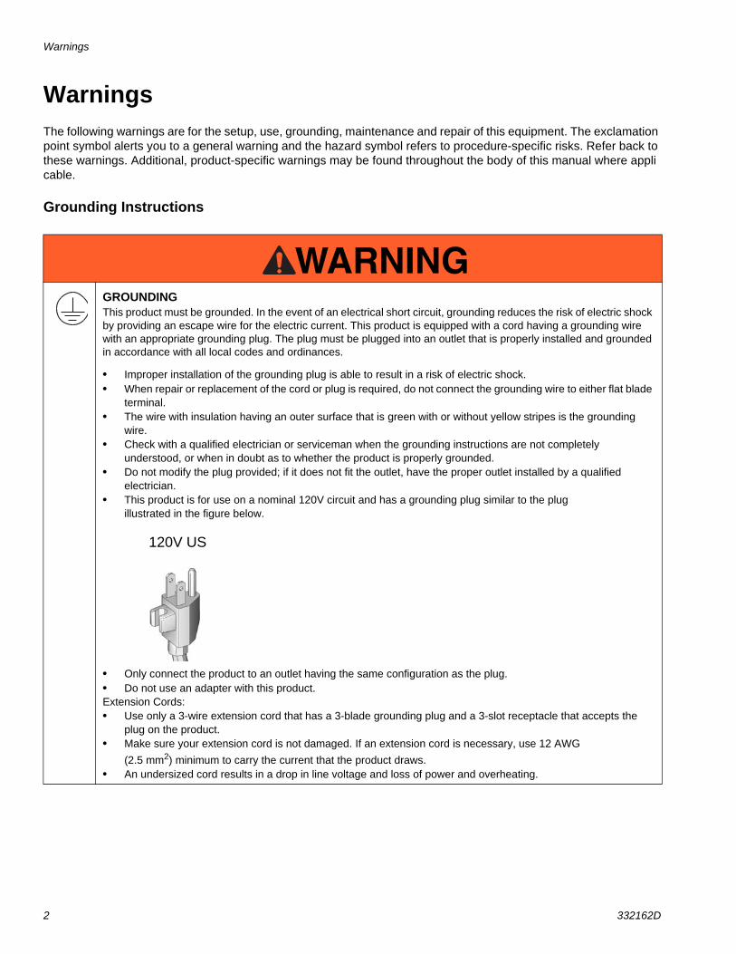
Air and fluid hoses: use only electrically conductive hoses with a maximum of 500 ft. (150 m) combined hose length to ensure grounding continuity. Check electrical resistance of hoses. If total resistance to ground exceeds 29 megohms, replace hose immediately.
Spray gun: ground through connection to a properly grounded fluid hose and pump.
Fluid supply container: follow local code.
Object being sprayed: follow local code.
Power Requirements100-120V units require 100-120 VAC, 60 Hz, 11A, 1 phase.
Extension Cords• If an extension cord is necessary, use a 3-wire, 12
AWG (2.5 mm2) minimum.
• Use an extension cord with an undamaged ground contact.
PailsSolvent and oil/based fluids: follow local code. Use only conductive metal pails, placed on a grounded surface. Do not place the pail on a nonconductive surface, such as paper or cardboard, which interrupts grounding continuity.
Do not place pail on a nonconductive surface such as paper or cardboard which interrupts grounding continuity.
Grounding a metal pail: connect a ground wire to the pail by clamping one end to pail and other end to a true earth ground such as a water pipe.
To maintain grounding continuity when flushing or relieving pressure: hold metal part of spray gun firmly to side of a grounded metal pail. Then trigger gun.
The equipment must be grounded to reduce the risk of static sparking. Static sparking can cause fumes to ignite or explode. Grounding provides an escape wire for the electric current.
The plug must be plugged into an outlet that is properly installed and grounded in accordance with all local codes and ordinances.
Do not modify plug! If it will not fit in outlet, have grounded outlet installed by a qualified electrician. Do not use an adapter.
ti4297a
120 volt plug
ground
ti5850a
ti5851a

General Repair Information
8 332162D
General Repair Information
• Keep all screws, nuts, washers, gaskets, and electrical fittings removed during repair procedures. These parts usually are not provided with replacement kits.
• Test repairs after problems are corrected.
• If sprayer does not operate properly, review repair procedure to verify you did it correctly. See Troubleshooting, page 9.
• Overspray may build up in the air passages. Remove any overspray and residue from air passages and openings in the enclosures whenever you service sprayer.
• Do not operate the sprayer without the motor shroud in place. Replace if damaged. Motor shroud directs cooling air around motor to prevent overheating and insulates the control board from accidental electric shock.
Flammable materials spilled on hot, bare, motor could cause fire or explosion. To reduce risk of burns, fire or explosion, do not operate sprayer with cover removed.
To reduce risk of serious injury, including electric shock:• Do not touch moving or electric parts with fingers
or tools while testing repair. • Unplug sprayer when power is not required for
testing. • Install all covers, gaskets, screws and washers
before you operate sprayer.
NOTICE• Do not run sprayer dry for more than 30 seconds.
Doing so could damage pump packings.
• Protect the internal drive parts of this sprayer from water. Openings in the cover allow for air cooling of the mechanical parts and electronics inside. If water gets in these openings, the sprayer could malfunction or be permanently damaged.
• Prevent pump corrosion and damage from freezing. Never leave water or water-base paint in sprayer when its not in use in cold weather. Freezing fluids can seriously damage sprayer. Store sprayer with Pump Armor to protect sprayer during storage.

Troubleshooting
332162D 9
Troubleshooting
ProblemWhat To Check
(If check is OK, go to next check)What To Do
(When check is not OK, refer to this column)
Motor Won’t Operate
Basic Fluid Pressure 1. Pressure control knob setting. Motor will not run if set at minimum (fully counter-clockwise).
Slowly increase pressure setting to see if motor starts.
2. Spray tip or fluid filter may be clogged.
Relieve pressure, page 6. Then clear clog or clean gun filter. Refer to gun instruction manual.
Basic Mechanical 1. Pump frozen or hardened paint Thaw sprayer if water or water-based paint has frozen in sprayer. Place sprayer in warm area to thaw. Do not start sprayer until thawed completely. If paint hardened (dried) in sprayer, replace pump packings. See page 13, Displacement Pump Replacement.
2. Displacement pump connecting rod pin. Pin must be completely pushed into connecting rod and retaining spring must be firmly in groove or pump pin.
Push pin into place and secure with spring retainer. See page 13, Displacement Pump Replacement.
3. Motor. Remove drive housing assembly. See page 15, Drive Housing Replacement. Try to rotate fan by hand.
Replace motor if fan won’t turn. See page 27, Motor Replacement.
Troubleshooting
10 332162D
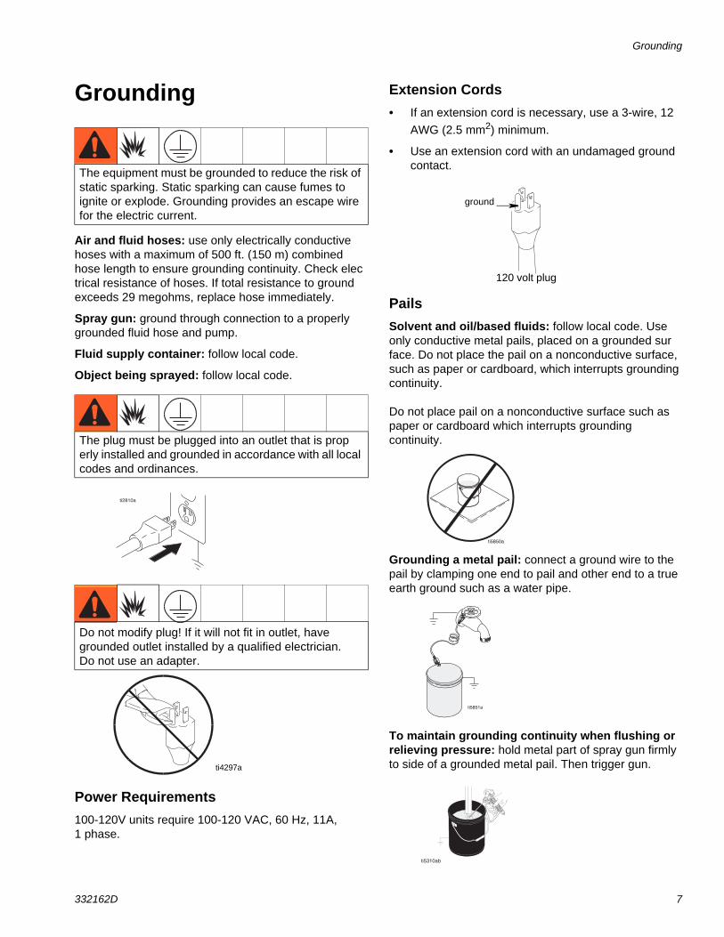
Basic ElectricalSee Wiring Diagram, page 28.
1. Electric supply. ON/OFF switch in OFF position. Meter must read 100-130 Vac.
Turn ON/OFF switch to ON position. Reset building circuit breaker, replace building fuses. Try another outlet.
2. Extension cord. Check extension cord continuity with volt meter.
Replace extension cord.
3. Sprayer power supply cord. Inspect for damage such as broken insulation or wires.
Replace power supply cord. See page 26, Power Cord Replacement.
4. Fuse. Check replaceable fuse on control board (next to ON/OFF switch).
Replace fuse after completing motor inspection. See page 21, Fuse Replacement.
5. Motor leads are securely fastened and properly connected to control board.
Replace loose terminals; crimp to leads. Be sure terminals are firmly connected.
Clean circuit board terminals. Securely reconnect leads.
6. Motor thermal switch. Yellow motor leads must have continuity through thermal switch.
Replace motor. See page 27, Motor Replacement.
7. Brush cap missing or loose brush lead connections.
Install brush cap or replace brushes if leads are damaged. See page 18, Motor Brush Replacement.
8. Brush length which must be greater than 1/4 in. (6mm).
NOTE: Brushes do not wear at the same rate on both sides of motor. Check both brushes.
Replace brushes. See page 18, Motor Brush Replacement.
9. Motor armature commutator for burn spots, gouges and extreme roughness.
Remove motor and have motor shop resurface commutator if possible. See page 18, Motor Replacement.
10. Motor armature for shorts using armature tester (growler) or perform spin test, page 16.
Replace motor. See page 18, Motor Replacement.
11. Pressure control not plugged in to control board.
Insert pressure control connector into control board.
ProblemWhat To Check
(If check is OK, go to next check)What To Do
(When check is not OK, refer to this column)

Troubleshooting
332162D 11
Low Output 1. Worn spray tip. Relieve pressure, page 6. Replace tip. Refer to gun instruction manual, 311861.
2. Verify pump does not continue to stroke when gun trigger is released.
Service pump. See page 13, Displacement Pump Replacement.
3. Drain valve leaking. Relieve pressure, page 6. Then repair drain valve. See page 24, Manifold Replacement.
4. Suction tube connections. Tighten any loose connections. Check o-ring on suction tube.
5. Electric supply with volt meter. Meter must read 100-130 Vac. Low voltages reduce sprayer performance.
Reset building circuit breaker; replace building fuse. Repair electrical outlet or try another outlet.
6. Extension cord size and length. Replace with a correct, grounded extension cord. See page 7, Grounding and Electric Requirements.
7. Leads from motor to circuit board for damaged or loose wire connectors. Inspect wiring insulation and terminals for signs of overheating.
Be sure male terminal pins are centered and firmly connected to female terminals. Replace any loose terminals or damaged wiring. Securely reconnect terminals.
8. Worn motor brushes which must be greater than 1/4 in. (6 mm).
Replace brushes. See page 18. Motor Brush Replacement.
9. Motor brushes binding in brush holders.
Clean brush holders. Remove carbon dust by using compressed air to blow out brush dust.
10. Low stall pressure. Turn pressure control knob fully clockwise.
Replace pressure control assembly. See page 22, Pressure Control Assembly Replacement.
11. Motor armature for shorts by using an armature tester (growler) or perform spin test, page 16.
Replace motor. See page 18, Motor Replacement.
ProblemWhat To Check
(If check is OK, go to next check)What To Do
(When check is not OK, refer to this column)
Troubleshooting
12 332162D
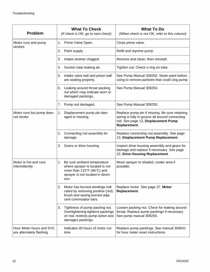
Motor runs and pump strokes
1. Prime Valve Open. Close prime valve.
2. Paint supply. Refill and reprime pump.
3. Intake strainer clogged. Remove and clean, then reinstall.
4. Suction tube leaking air. Tighten nut. Check o-ring on tube.
5. Intake valve ball and piston ball are seating properly.
See Pump Manual 309250. Strain paint before using to remove particles that could clog pump.
6. Leaking around throat packing nut which may indicate worn or damaged packings.
See Pump Manual 309250.
7. Pump rod damaged. See Pump Manual 309250.
Motor runs but pump does not stroke
1. Displacement pump pin damaged or missing.
Replace pump pin if missing. Be sure retaining spring is fully in groove all around connecting rod. See page 13, Displacement Pump Replacement.
2. Connecting rod assembly for damage.
Replace connecting rod assembly. See page 13, Displacement Pump Replacement.
3. Gears or drive housing. Inspect drive housing assembly and gears for damage and replace if necessary. See page 15, Drive Housing Replacement.
Motor is hot and runs intermittently
1. Be sure ambient temperature where sprayer is located is not more than 115°F (46°C) and sprayer is not located in direct sun.
Move sprayer to shaded, cooler area if possible.
2. Motor has burned windings indicated by removing positive (red) brush and seeing burned adjacent commutator bars.
Replace motor. See page 27, Motor Replacement.
3. Tightness of pump packing nut. Overtightening tightens packings on rod, restricts pump action and damages packings.
Loosen packing nut. Check for leaking around throat. Replace pump packings if necessary. See pump manual 309250.
Hour Meter hours and SVC are alternately flashing
Indicates 40 hours of motor run time
Replace pump packings. See manual 309541 for hour meter reset instructions.
ProblemWhat To Check
(If check is OK, go to next check)What To Do
(When check is not OK, refer to this column)
Displacement Pump Replacement
332162D 13
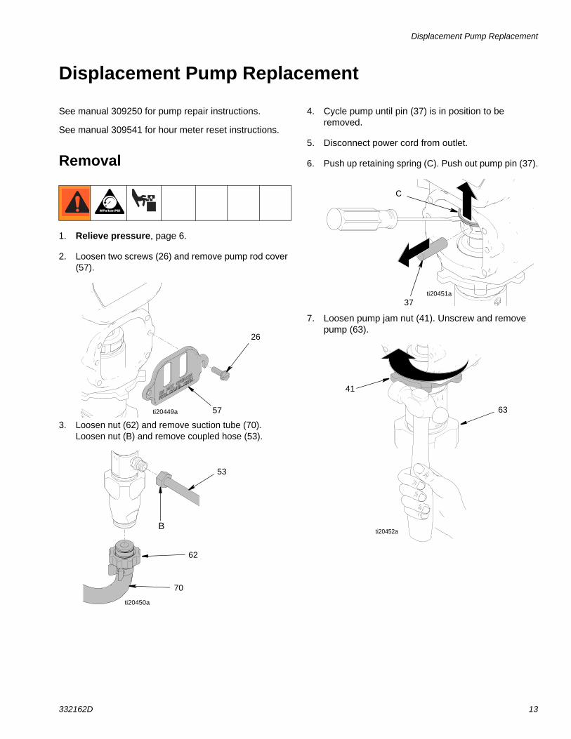
Displacement Pump Replacement
See manual 309250 for pump repair instructions.
See manual 309541 for hour meter reset instructions.
Removal
1. Relieve pressure, page 6.
2. Loosen two screws (26) and remove pump rod cover (57).
3. Loosen nut (62) and remove suction tube (70). Loosen nut (B) and remove coupled hose (53).
4. Cycle pump until pin (37) is in position to be removed.
5. Disconnect power cord from outlet.
6. Push up retaining spring (C). Push out pump pin (37).
7. Loosen pump jam nut (41). Unscrew and remove pump (63).
26
57ti20449a
53
B
62
70
ti20450a
C
37ti20451a
41
63
ti20452a

Displacement Pump Replacement
14 332162D
Installation1. Extend pump piston rod fully. Apply grease to top of
pump rod (D). Install jam nut (41) on pump threads.
2. Install pump rod (D) into connecting rod (29).
3. Install pump pin (37). Verify retainer spring (29a) is in groove over pump pin.
4. Push pump (63) up until pump threads engage.
5. Screw in pump until threads are flush with top of drive housing opening.
6. Align pump outlet (E) to back.
7. Screw jam nut (41) up onto pump until nut stops. Tighten jam nut by hand, then tap 1/8 to 1/4 turn with a 20 oz (maximum) hammer to approximately 75 ft-lb (102 N•m).
8. Install suction tube adapter (70) and coupled hose (53). Tighten nuts (62) and (B).
.
9. Install pump rod cover (57) with screws (26).
10. Fill packing nut with Graco TSL until fluid flows onto top of seal.
If pump pin works loose, parts could break off due to force of pumping action, project through the air, and result in serious injury or property damage. To avoid, ensure the retainer spring is installed properly.
D
41
ti20453a
29
2929a37
ti9144a
ti20454a
ti6111a
E
41
ti20455a
53B
62
70
ti20450a
ti20449a57
26
ti20456a

Drive Housing Replacement
332162D 15
Drive Housing Replacement
Removal1. Relieve pressure, page 6.
2. Remove pump (63). Displacement Pump Replacement, page 13.
3. Disconnect power cord from outlet.
4. Remove two screws (26) and cover (67).
5. Remove screw (48) and four screws (44).
6. Pull drive housing (35) out of motor front end bell.
7. Remove gear cluster (34) and (42) and thrust bearing (43) from drive housing.
NOTE: Do not drop gear cluster (34) and (42) when removing drive housing (35). Gear cluster may stay engaged in motor front end bell or drive housing.
Installation1. Apply a liberal coat of grease to gears and needle
bearing surfaces. Install thrust bearing (43) and gears (42) and (34) in motor front end bell.
2. Push drive housing (35) into motor front end bell. Insert gear crank (34) through hole in connecting rod (29).
3. Install four screws (44) and screw (48).
4. Install cover (67) with two screws (26).
5. Install pump (63). Displacement Pump Replacement, page 13.
48
67
26
3443
44
35
ti20457a
NeedleBearing Surfaces
34
42
43
ti20459a
26
ti20462a
67
44
2934
35
Spin Test
16 332162D
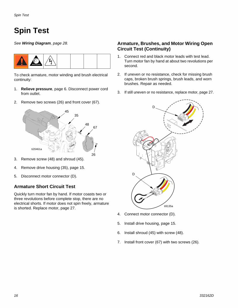
Spin TestSee Wiring Diagram, page 28.
To check armature, motor winding and brush electrical continuity:
1. Relieve pressure, page 6. Disconnect power cord from outlet.
2. Remove two screws (26) and front cover (67).
3. Remove screw (48) and shroud (45).
4. Remove drive housing (35), page 15.
5. Disconnect motor connector (D).
Armature Short Circuit TestQuickly turn motor fan by hand. If motor coasts two or three revolutions before complete stop, there are no electrical shorts. If motor does not spin freely, armature is shorted. Replace motor, page 27.
Armature, Brushes, and Motor Wiring Open Circuit Test (Continuity)1. Connect red and black motor leads with test lead.
Turn motor fan by hand at about two revolutions per second.
2. If uneven or no resistance, check for missing brush caps, broken brush springs, brush leads, and worn brushes. Repair as needed.
3. If still uneven or no resistance, replace motor, page 27.
4. Connect motor connector (D).
5. Install drive housing, page 15.
6. Install shroud (45) with screw (48).
7. Install front cover (67) with two screws (26).
26
6748
3545
ti20461a
D
ti9135a
D
Fan Replacement
332162D 17
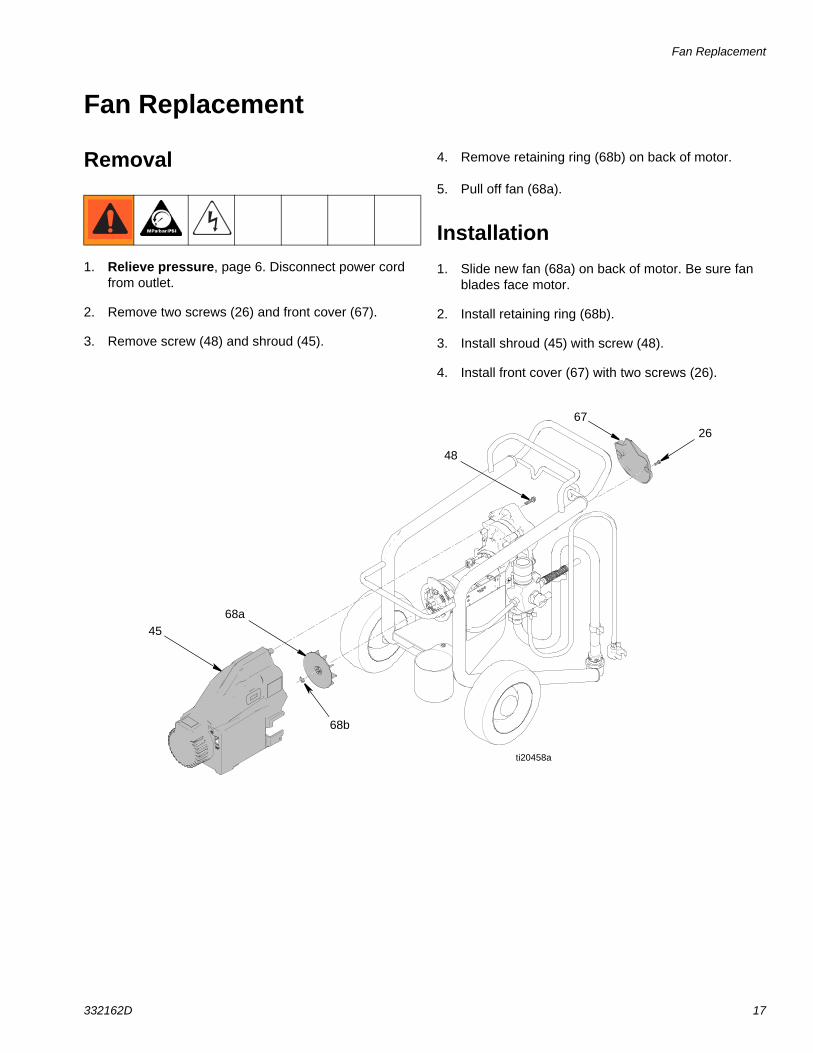
Fan Replacement
Removal
1. Relieve pressure, page 6. Disconnect power cord from outlet.
2. Remove two screws (26) and front cover (67).
3. Remove screw (48) and shroud (45).
4. Remove retaining ring (68b) on back of motor.
5. Pull off fan (68a).
Installation1. Slide new fan (68a) on back of motor. Be sure fan
blades face motor.
2. Install retaining ring (68b).
3. Install shroud (45) with screw (48).
4. Install front cover (67) with two screws (26).
68a
26
45
ti20458a
48
67
68b
Motor Brush Replacement
18 332162D
Motor Brush ReplacementSee Wiring Diagram, page 28.
RemovalReplace brushes worn to less than 1/4 in. (6 mm). Brushes wear differently on each side of motor, check both sides.
1. Relieve pressure, page 6. Disconnect power cord from outlet.
2. Remove two screws (26) and front cover (67).
3. Remove screw (48) and shroud (45).
4. Disconnect motor connector (D) from control board (59).
5. Cut tie wrap (F).
6. Locate two yellow wires (C). Cut each yellow wire at the center.
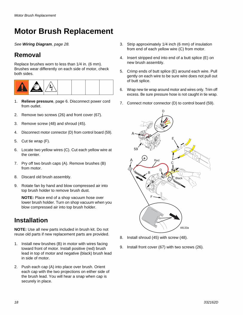
7. Pry off two brush caps (A). Remove brushes (B) from motor.
8. Discard old brush assembly.
9. Rotate fan by hand and blow compressed air into top brush holder to remove brush dust.
NOTE: Place end of a shop vacuum hose over lower brush holder. Turn on shop vacuum when you blow compressed air into top brush holder.
InstallationNOTE: Use all new parts included in brush kit. Do not reuse old parts if new replacement parts are provided.
1. Install new brushes (B) in motor with wires facing toward front of motor. Install positive (red) brush lead in top of motor and negative (black) brush lead in side of motor.
2. Push each cap (A) into place over brush. Orient each cap with the two projections on either side of the brush lead. You will hear a snap when cap is securely in place.
3. Strip approximately 1/4 inch (6 mm) of insulation from end of each yellow wire (C) from motor.
4. Insert stripped end into end of a butt splice (E) on new brush assembly.
5. Crimp ends of butt splice (E) around each wire. Pull gently on each wire to be sure wire does not pull out of butt splice.
6. Wrap new tie wrap around motor and wires only. Trim off excess. Be sure pressure hose is not caught in tie wrap.
7. Connect motor connector (D) to control board (59).
8. Install shroud (45) with screw (48).
9. Install front cover (67) with two screws (26).
A
B
-
+
D
E
F
D
A
Red
Black
C
B
D
ti9133a
59
Control Board Replacement
332162D 19
Control Board ReplacementSee Wiring Diagram, page 28.
Removal1. Relieve pressure, page 6. Disconnect power cord
from outlet.
2. Remove two screws (26) and front cover (67). Remove screw (48) and shroud (45).
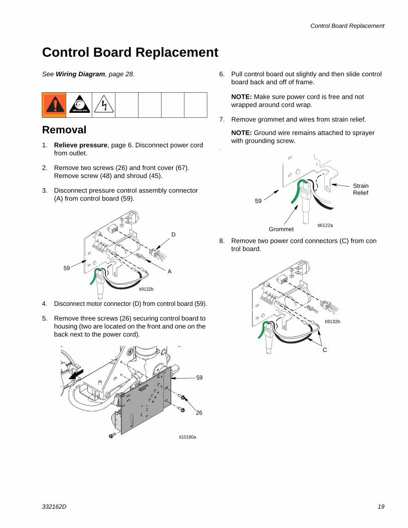
3. Disconnect pressure control assembly connector (A) from control board (59).
4. Disconnect motor connector (D) from control board (59).
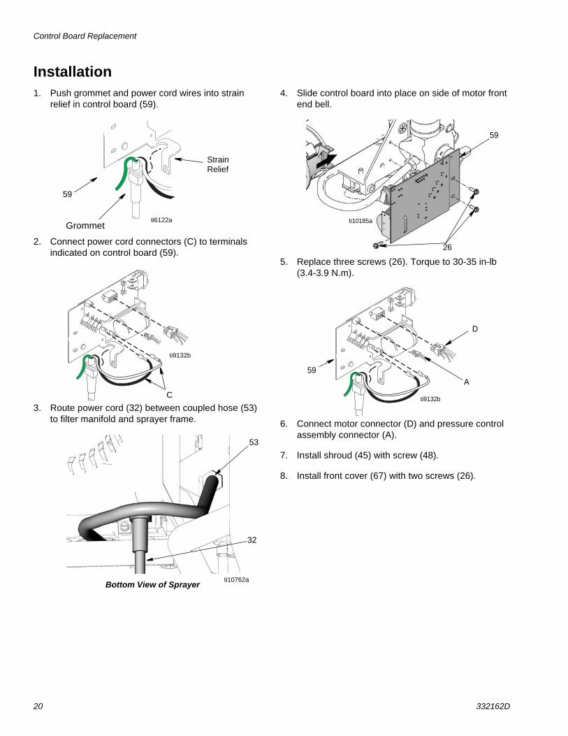
5. Remove three screws (26) securing control board to housing (two are located on the front and one on the back next to the power cord).
6. Pull control board out slightly and then slide control board back and off of frame.
NOTE: Make sure power cord is free and not wrapped around cord wrap.
7. Remove grommet and wires from strain relief.
NOTE: Ground wire remains attached to sprayer with grounding screw.
.
8. Remove two power cord connectors (C) from control board.
ti9132b
59
D
A
26
59
ti10180a
ti6122a
59
Grommet
StrainRelief
C
ti9132b
Control Board Replacement
20 332162D
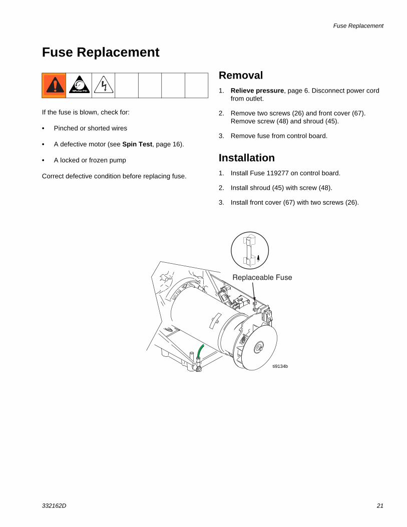
Installation1. Push grommet and power cord wires into strain
relief in control board (59).
2. Connect power cord connectors (C) to terminals indicated on control board (59).
3. Route power cord (32) between coupled hose (53) to filter manifold and sprayer frame.
4. Slide control board into place on side of motor front end bell.
5. Replace three screws (26). Torque to 30-35 in-lb (3.4-3.9 N.m).
6. Connect motor connector (D) and pressure control assembly connector (A).
7. Install shroud (45) with screw (48).
8. Install front cover (67) with two screws (26).
ti6122a
59
Grommet
StrainRelief
C
ti9132b
Bottom View of Sprayerti10762a
53
32
26
59
ti10185a
ti9132b
59
D
A
Fuse Replacement
332162D 21
Fuse Replacement
If the fuse is blown, check for:
• Pinched or shorted wires
• A defective motor (see Spin Test, page 16).
• A locked or frozen pump
Correct defective condition before replacing fuse.
Removal1. Relieve pressure, page 6. Disconnect power cord
from outlet.
2. Remove two screws (26) and front cover (67). Remove screw (48) and shroud (45).
3. Remove fuse from control board.
Installation1. Install Fuse 119277 on control board.
2. Install shroud (45) with screw (48).
3. Install front cover (67) with two screws (26).
Replaceable Fuse
ti9134b

Pressure Control Assembly Replacement
22 332162D
Pressure Control Assembly ReplacementSee Wiring Diagram, page 28.
Removal1. Relieve pressure, page 6. Disconnect power cord
from outlet.
2. Remove two screws (26) and front cover (67).
3. Remove screw (48) and shroud (45).
4. Disconnect pressure switch connector (A) from control board (59). Pull bushing (49) from hole (K).
5. Pull wires through hole (K).
6. Turn pressure control knob (36) counter clockwise as far as you can to access flats on either side of pressure control.
7. Loosen and unscrew pressure control.
NOTE: If you plan to reuse pressure control, be careful not to damage or tangle wires when unscrewing pressure control.
8. Remove pressure control.
26
6748
3545
ti20461a
59
A
K 49ti10168a
36
ti10173a
Pressure Control Assembly Replacement
332162D 23
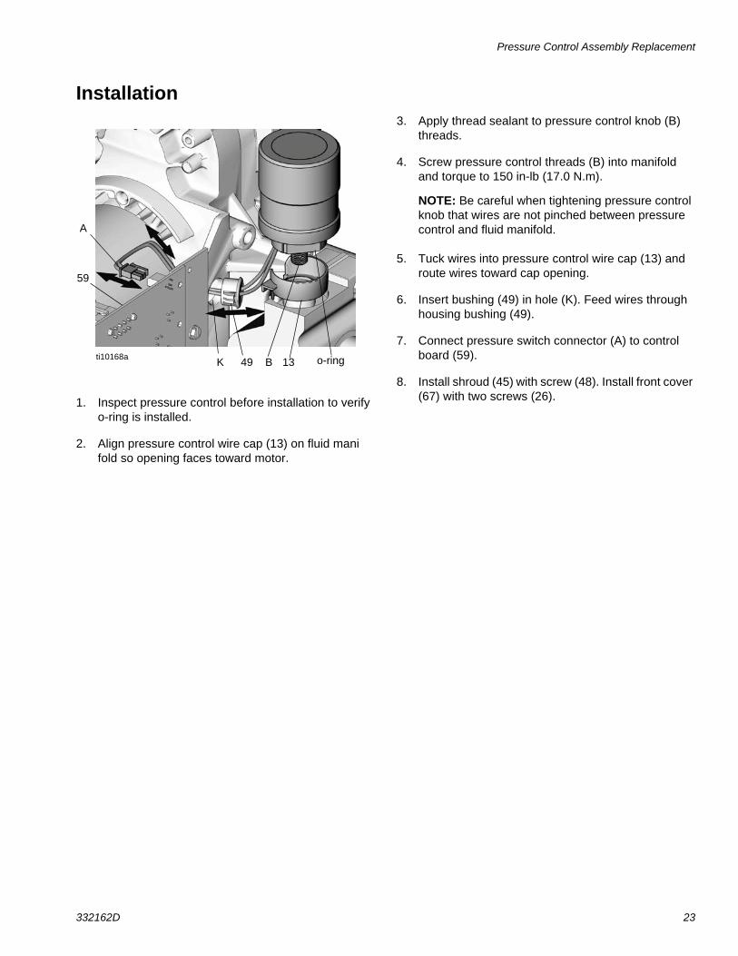
Installation
1. Inspect pressure control before installation to verify o-ring is installed.
2. Align pressure control wire cap (13) on fluid manifold so opening faces toward motor.
3. Apply thread sealant to pressure control knob (B) threads.
4. Screw pressure control threads (B) into manifold and torque to 150 in-lb (17.0 N.m).
NOTE: Be careful when tightening pressure control knob that wires are not pinched between pressure control and fluid manifold.
5. Tuck wires into pressure control wire cap (13) and route wires toward cap opening.
6. Insert bushing (49) in hole (K). Feed wires through housing bushing (49).
7. Connect pressure switch connector (A) to control board (59).
8. Install shroud (45) with screw (48). Install front cover (67) with two screws (26).
K o-ring
A
49
59
13ti10168a B
Drain Valve Replacement
24 332162D
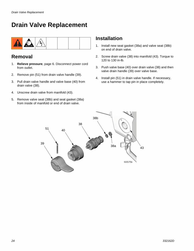
Drain Valve Replacement
Removal1. Relieve pressure, page 6. Disconnect power cord
from outlet.
2. Remove pin (51) from drain valve handle (39).
3. Pull drain valve handle and valve base (40) from drain valve (38).
4. Unscrew drain valve from manifold (43).
5. Remove valve seat (38b) and seat gasket (38a) from inside of manifold or end of drain valve.
Installation1. Install new seat gasket (38a) and valve seat (38b)
on end of drain valve.
2. Screw drain valve (38) into manifold (43). Torque to 120 to 130 in-lb.
3. Push valve base (40) over drain valve (38) and then valve drain handle (39) over valve base.
4. Install pin (51) in drain valve handle. If necessary, use a hammer to tap pin in place completely.
38
4051
39
38b
38a
ti10170a
43
Drain Line Replacement
332162D 25
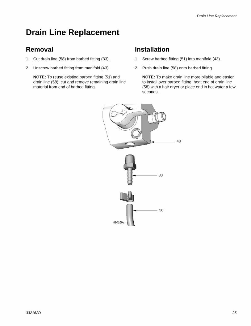
Drain Line Replacement
Removal1. Cut drain line (58) from barbed fitting (33).
2. Unscrew barbed fitting from manifold (43).
NOTE: To reuse existing barbed fitting (51) and drain line (58), cut and remove remaining drain line material from end of barbed fitting.
Installation1. Screw barbed fitting (51) into manifold (43).
2. Push drain line (58) onto barbed fitting.
NOTE: To make drain line more pliable and easier to install over barbed fitting, heat end of drain line (58) with a hair dryer or place end in hot water a few seconds.
33
58
ti10169a
43
Power Cord Replacement
26 332162D
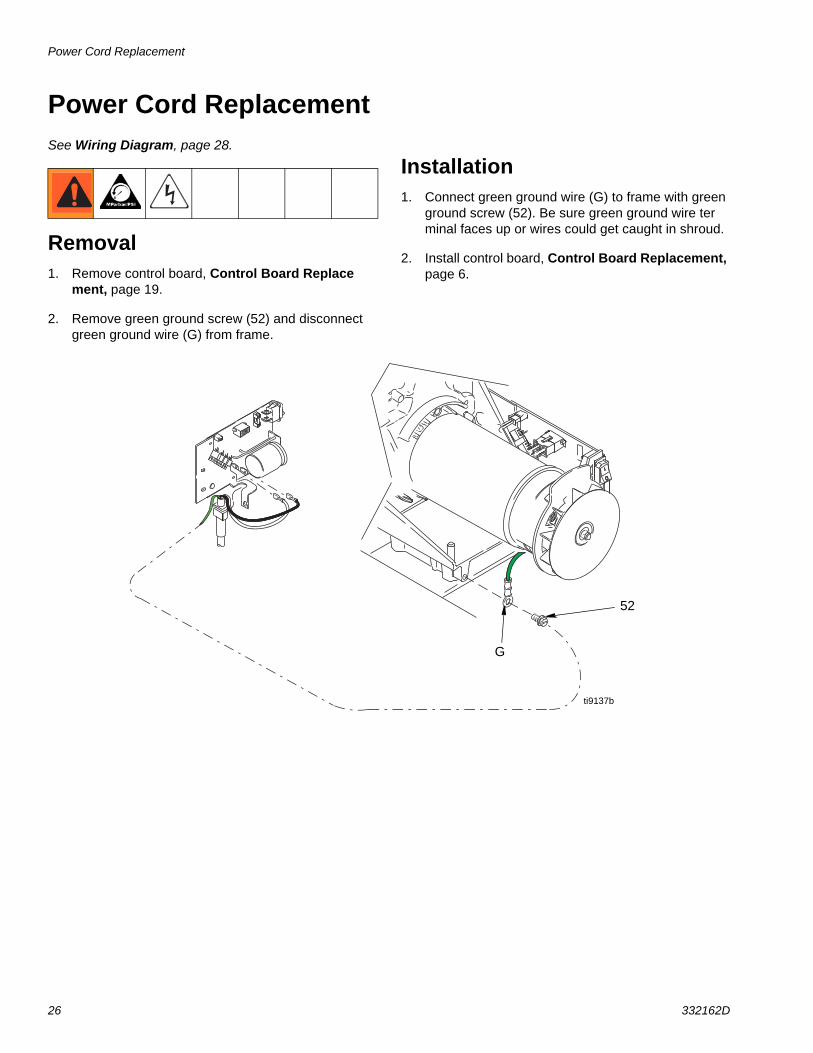
Power Cord ReplacementSee Wiring Diagram, page 28.
Removal1. Remove control board, Control Board Replace
ment, page 19.
2. Remove green ground screw (52) and disconnect green ground wire (G) from frame.
Installation 1. Connect green ground wire (G) to frame with green
ground screw (52). Be sure green ground wire terminal faces up or wires could get caught in shroud.
2. Install control board, Control Board Replacement, page 6.
G
52
ti9137b
Motor Replacement
332162D 27
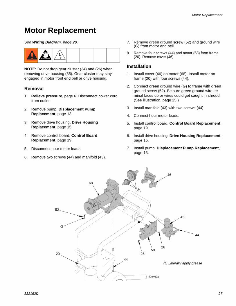
Motor ReplacementSee Wiring Diagram, page 28.
NOTE: Do not drop gear cluster (34) and (26) when removing drive housing (35). Gear cluster may stay engaged in motor front end bell or drive housing.
Removal1. Relieve pressure, page 6. Disconnect power cord
from outlet.
2. Remove pump, Displacement Pump Replacement, page 13.
3. Remove drive housing, Drive Housing Replacement, page 15.
4. Remove control board, Control Board Replacement, page 19.
5. Disconnect hour meter leads.
6. Remove two screws (44) and manifold (43).
7. Remove green ground screw (52) and ground wire (G) from motor end bell.
8. Remove four screws (44) and motor (68) from frame (20). Remove cover (46).
Installation1. Install cover (46) on motor (68). Install motor on
frame (20) with four screws (44).
2. Connect green ground wire (G) to frame with green ground screw (52). Be sure green ground wire terminal faces up or wires could get caught in shroud. (See illustration, page 25.)
3. Install manifold (43) with two screws (44).
4. Connect hour meter leads.
5. Install control board, Control Board Replacement, page 19.
6. Install drive housing. Drive Housing Replacement, page 15.
7. Install pump. Displacement Pump Replacement, page 13.
1
26
44
59
43
44
68
1 Liberally apply grease
ti20460a
20
G
52
46
26
Wiring Diagram
28 332162D
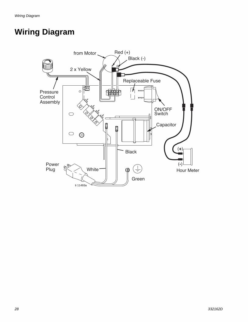
Wiring Diagram
Red (+)Black (-)
PressureControlAssembly
PowerPlug White
Green
Black
from Motor
2 x Yellow
ON/OFFSwitch
Capacitor
Replaceable Fuse
Hour Meter(-)
(+)
ti 11493a

Parts
332162D 29
Parts
73
74
1
68
46
35
57
4234
43
29
37
63
41
50
47
26
67
26
49 48
45
44
53
55
54
79
71
6060
69
70
62
64
65
61
78
82
83
85
31
4
56
2
3
8
7
75
77
68a
68b
ti20463a
86
ti20463a
Parts
30 332162D
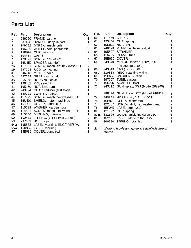
Parts List
Ref. Part Description Qty.1 246250 FRAME, cart, lo 12 287488 HANDLE, assy, lo cart 13 109032 SCREW, mach, pnh 44 195766 WHEEL, semi pneumatic 25 15B999 CLIP, retaining 26 104811 CAP, hub 27 120091 SCREW, 1/4-20 x 2 48 16U457 SPACER, standoff 426 117501 SCREW, mach, slot hex wash HD 729 287053 ROD, connecting 131 246013 METER, hour 134 287054 GEAR, crankshaft 135 255168 HOUSING, drive 137 196762 PIN, straight 141 195150 NUT, jam, pump 142 249194 GEAR, reducer (first stage) 143 180131 BEARING, thrust 144 117493 SCREW, mach, hex washer HD 645 16U501 SHIELD, motor, machined 146 15J651 COVER, 210/190ES 147 115099 WASHER, garden hose 148 114531 SCREW, mach, hex washer HD 149 115756 BUSHING, universal 150 162453 FITTING, (1/4 npsm x 1/4 npt) 253 287003 HOSE, cpld 154 195833 LABEL, warning, ENG/FRE/SPA 155 15K359 LABEL, warning 157 15B589 COVER, pump rod 1
60 117559 O-RING 261 195400 CLIP, spring 162 15E813 NUT, jam 163 246428 PUMP, displacement, st 164 195697 STRAINER 165 116295 CLAMP, tube 167 15E630 COVER 168 249040 MOTOR, electric, 120V, 390
(includes 68a, 68b)1
68a 249043 FAN (includes 68b) 168b 119653 RING, retaining o-ring 169 15B652 WASHER, suction 170 197607 TUBE, suction 171 15R237 ADAPTER, inlet 173 243012
288430
GUN, spray, SG3 (Model 262906)
GUN, Spray, FTX (Model 24R927)
1
174 240794 HOSE, cpld, 1/4 in. x 50 ft 175 15B870 CUP, suction/drain 177 122667 SCREW, drill, hex washer head 278 15R247 LABEL, front, 210 182 121092 CLIP, spring 183 332165 GUIDE, quick tips guide 210 185 15Y118 LABEL, Made in the USA 186 196750 SPRING, retaining 1
Warning labels and guide are available free of charge.
Ref. Part Description Qty.
Parts Drawing
332162D 31
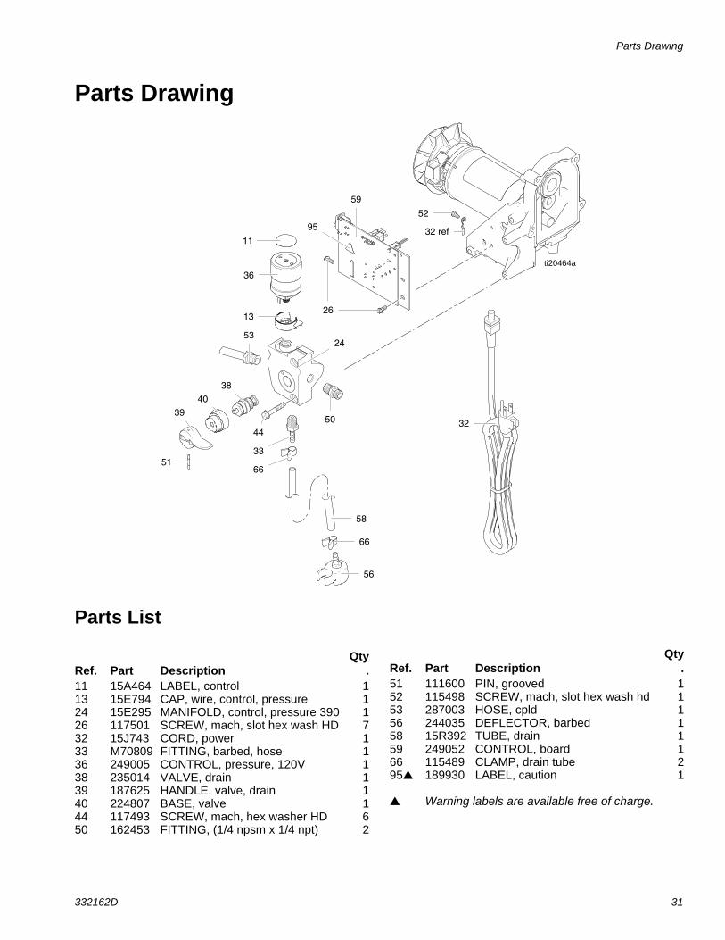
Parts Drawing
Parts List
24
13
36
11
38
33
40
39
51
59
26
52
50
53
44
58
56
32
66
66
95
26
32 ref
ti20464a
Ref. Part DescriptionQty
.11 15A464 LABEL, control 113 15E794 CAP, wire, control, pressure 124 15E295 MANIFOLD, control, pressure 390 126 117501 SCREW, mach, slot hex wash HD 732 15J743 CORD, power 133 M70809 FITTING, barbed, hose 136 249005 CONTROL, pressure, 120V 138 235014 VALVE, drain 139 187625 HANDLE, valve, drain 140 224807 BASE, valve 144 117493 SCREW, mach, hex washer HD 650 162453 FITTING, (1/4 npsm x 1/4 npt) 2
51 111600 PIN, grooved 152 115498 SCREW, mach, slot hex wash hd 153 287003 HOSE, cpld 156 244035 DEFLECTOR, barbed 158 15R392 TUBE, drain 159 249052 CONTROL, board 166 115489 CLAMP, drain tube 295 189930 LABEL, caution 1
Warning labels are available free of charge.
Ref. Part DescriptionQty
.

All written and visual data contained in this document reflects the latest product information available at the time of publication. Graco reserves the right to make changes at any time without notice.
For patent information, see www.graco.com/patents.
Original instructions. This manual contains English. MM 332162
Graco Headquarters: MinneapolisInternational Offices: Belgium, China, Japan, Korea
GRACO INC. AND SUBSIDIARIES P.O. BOX 1441 MINNEAPOLIS, MN 55440-1441Copyright 2012, Graco Inc. All Graco manufacturing are registered to ISO 9001
www.graco.comRevised D Aprilt 2016
Graco Standard WarrantyGraco warrants all equipment referenced in this document which is manufactured by Graco and bearing its name to be free from defects in material and workmanship on the date of sale to the original purchaser for use. With the exception of any special, extended, or limited warranty published by Graco, Graco will, for a period of twelve months from the date of sale, repair or replace any part of the equipment determined by Graco to be defective. This warranty applies only when the equipment is installed, operated and maintained in accordance with Graco’s written recommendations.
This warranty does not cover, and Graco shall not be liable for general wear and tear, or any malfunction, damage or wear caused by faulty installation, misapplication, abrasion, corrosion, inadequate or improper maintenance, negligence, accident, tampering, or substitution of non-Graco component parts. Nor shall Graco be liable for malfunction, damage or wear caused by the incompatibility of Graco equipment with structures, accessories, equipment or materials not supplied by Graco, or the improper design, manufacture, installation, operation or maintenance of structures, accessories, equipment or materials not supplied by Graco.
This warranty is conditioned upon the prepaid return of the equipment claimed to be defective to an authorized Graco distributor for verification of the claimed defect. If the claimed defect is verified, Graco will repair or replace free of charge any defective parts. The equipment will be returned to the original purchaser transportation prepaid. If inspection of the equipment does not disclose any defect in material or workmanship, repairs will be made at a reasonable charge, which charges may include the costs of parts, labor, and transportation.
THIS WARRANTY IS EXCLUSIVE, AND IS IN LIEU OF ANY OTHER WARRANTIES, EXPRESS OR IMPLIED, INCLUDING BUT NOT LIMITED TO WARRANTY OF MERCHANTABILITY OR WARRANTY OF FITNESS FOR A PARTICULAR PURPOSE.
Graco’s sole obligation and buyer’s sole remedy for any breach of warranty shall be as set forth above. The buyer agrees that no other remedy (including, but not limited to, incidental or consequential damages for lost profits, lost sales, injury to person or property, or any other incidental or consequential loss) shall be available. Any action for breach of warranty must be brought within two (2) years of the date of sale.
GRACO MAKES NO WARRANTY, AND DISCLAIMS ALL IMPLIED WARRANTIES OF MERCHANTABILITY AND FITNESS FOR A PARTICULAR PURPOSE, IN CONNECTION WITH ACCESSORIES, EQUIPMENT, MATERIALS OR COMPONENTS SOLD BUT NOT MANUFACTURED BY GRACO. These items sold, but not manufactured by Graco (such as electric motors, switches, hose, etc.), are subject to the warranty, if any, of their manufacturer. Graco will provide purchaser with reasonable assistance in making any claim for breach of these warranties.
In no event will Graco be liable for indirect, incidental, special or consequential damages resulting from Graco supplying equipment hereunder, or the furnishing, performance, or use of any products or other goods sold hereto, whether due to a breach of contract, breach of warranty, the negligence of Graco, or otherwise.
Graco InformationFor the latest information about Graco products, visit www.graco.com.
For patent information, see www.graco.com/patents.
TO PLACE AN ORDER, contact your Graco distributor or call 1-800-690-2894 to identify the nearest distributor.