Embed Size (px)
Citation preview

This is an electronic reprint of the original article.This reprint may differ from the original in pagination and typographic detail.
Powered by TCPDF (www.tcpdf.org)
This material is protected by copyright and other intellectual property rights, and duplication or sale of all or part of any of the repository collections is not permitted, except that material may be duplicated by you for your research use or educational purposes in electronic or print form. You must obtain permission for any other use. Electronic or print copies may not be offered, whether for sale or otherwise to anyone who is not an authorised user.
Renzo, Marco Di; Zappone, Alessio; Debbah, Merouane; Alouini, Mohamed Slim; Yuen,Chau; Rosny, Julien De; Tretiakov, SergeiSmart Radio Environments Empowered by Reconfigurable Intelligent Surfaces: How it Works,State of Research, and Road Ahead
Published in:IEEE Journal on Selected Areas in Communications
DOI:10.1109/JSAC.2020.3007211
Published: 01/11/2020
Document VersionPeer reviewed version
Please cite the original version:Renzo, M. D., Zappone, A., Debbah, M., Alouini, M. S., Yuen, C., Rosny, J. D., & Tretiakov, S. (2020). SmartRadio Environments Empowered by Reconfigurable Intelligent Surfaces: How it Works, State of Research, andRoad Ahead. IEEE Journal on Selected Areas in Communications, 38(11), 2450-2525. [9140329].https://doi.org/10.1109/JSAC.2020.3007211

1
Smart Radio Environments Empowered byReconfigurable Intelligent Surfaces:
How it Works, State of Research, and Road AheadMarco Di Renzo, Fellow, IEEE, Alessio Zappone, Senior Member, IEEE, Merouane Debbah, Fellow, IEEE,
Mohamed-Slim Alouini, Fellow, IEEE, Chau Yuen, Senior Member, IEEE, Julien de Rosny, andSergei Tretyakov, Fellow, IEEE
Abstract—What is a reconfigurable intelligent surface? Whatis a smart radio environment? What is a metasurface? How dometasurfaces work and how to model them? How to reconcilethe mathematical theories of communication and electromag-netism? What are the most suitable uses and applications ofreconfigurable intelligent surfaces in wireless networks? Whatare the most promising smart radio environments for wirelessapplications? What is the current state of research? What arethe most important and challenging research issues to tackle?
These are a few of the many questions that we investigate inthis short opus, which has the threefold objective of introducingthe emerging research field of smart radio environments empow-ered by reconfigurable intelligent surfaces, putting forth the needof reconciling and reuniting C. E. Shannon’s mathematical theoryof communication with G. Green’s and J. C. Maxwell’s math-ematical theories of electromagnetism, and reporting pragmaticguidelines and recipes for employing appropriate physics-basedmodels of metasurfaces in wireless communications.
Index Terms—5G, 6G, reconfigurable intelligent surfaces,smart radio environments, mathematical theory of communica-tion, mathematical theory of electromagnetism.
I. INTRODUCTION
Increasing data traffic. Wireless connectivity is regardedas a fundamental need for our society. Between 2020 and 2030,it is forecast that the data traffic of the global Internet protocol(IP) will increase by 55% each year, eventually reaching 5,016exabytes [1], with data rates scaling up to 1 Tb/s [2]. Besidessupporting very high data rates, future wireless networks areexpected to offer several other heterogeneous services, whichinclude sensing, localization, low-latency and ultra-reliablecommunications. Fifth-generation (5G) networks are, however,
Manuscript received April 20, 2020.M. Di Renzo is with Universite Paris-Saclay, CNRS and Centrale-
Supelec, Laboratoire des Signaux et Systemes, Gif-sur-Yvette, France. (e-mail: [email protected]). The research activity of M. DiRenzo was supported by the European Commission through the H2020ARIADNE project under grant 871464.
A. Zappone is with University of Cassino and Lazio Meridionale, Cassino,Italy. (e-mail: [email protected]).
M. Debbah is with Huawei France R&D, Boulogne-Billancourt, France.(e-mail: [email protected]).
M.-S. Alouini is with King Abdullah University of Science and Technology(KAUST), Kingdom of Saudi Arabia. (e-mail: [email protected]).
C. Yuen is with Singapore University of Technology and Design (SUTD),Singapore. (e-mail: [email protected]).
J. de Rosny is with Paris Sciences & Lettres, CNRS, Institut Langevin,Paris, France. (e-mail: [email protected]).
S. Tretyakov is with Aalto University, Helsinki, Finland. (e-mail:[email protected]).
not designed to meet these requirements. As the demands andneeds become more stringent, in fact, fundamental limitationsarise, which are ultimately imposed by the inherent nature ofwireless operation.
Current network design assumptions. The first five gen-erations of wireless networks have been designed by adher-ing to the postulates that the wireless environment betweencommunicating devices (i) is fixed by nature, (ii) cannot bemodified, (iii) can be only compensated through the design ofsophisticated transmission and reception schemes. After fivegenerations of wireless networks, however, the improvementsthat can be expected by operating only on the end-pointsof the wireless environment may not be sufficient to fulfillthe challenging requirements of future wireless networks. Thesixth generation (6G) of communication networks is, on theother hand, envisioned to require a new architectural platformthat performs joint communication, sensing, localization, andcomputing, while ensuring ultra-high throughput, ultra-lowlatency, and ultra-high reliability, which need to be flexiblycustomized in real-time.
An emerging paradigm: Programming the environment.Major performance gains can be expected by breaking freefrom the postulate that regards the wireless environment asan uncontrollable element. For example, a typical base stationtransmits radio waves of the order of magnitude of Watts whilea user equipment detects signals of the order of magnitude ofµWatts. The rest of the power is, in general, wasted in differentways through the environment by, e.g., generating interferenceto other network elements or creating security threats, sincethe propagation of radio waves through the wireless channelcannot be controlled and customized after they are emittedfrom the transmitters and before they are received by thereceivers. An intriguing question was recently brought to theattention of the wireless community: Can this status quo befundamentally overcome?
The road to smart radio environments. At the time ofwriting, no precise answer to this question can be given. Aplethora of research activities have, however, recently flour-ished in an attempt of tackling and putting this question inthe context of the most promising technologies that weredeveloped during the last decades and that are envisioned toconstitute the backbone of 5G networks. The current long-termvision for overcoming the limitations of 5G networks consistsof turning the wireless environment into an optimization

2
Fig. 1: Radio environments vs. smart radio environments.
variable, which, jointly with the transmitters and receivers,can be controlled and programmed rather than just adapted to.This approach is widely referred to as smart radio environment(SRE) or, more recently, intelligent radio environment (IRE),or “Wireless 2.0” in order to emphasize the conceptual andfundamental difference with the designs and optimizationcriteria adopted in current and past generations of wirelessnetworks. Conceptually, the vision of SREs is depicted in Fig.1.
Structure of the paper. The objective of the present paperis to provide the readers with a comprehensive and criticaloverview of the fundamental technology enablers, the mainoperating principles and envisioned potential applications, thecurrent state of research, and the open research challenges ofthe emerging concept of SREs. To this end, the present paperis organized in six sections.• In Section II, the concept of reconfigurable intelligent
surface (RIS), as the technology enabler to realize thevision of SREs, is introduced.
• In Section III, the concept of SREs is introduced in moredetail by reporting major examples of application and usecases.
• In Section IV, a communication-theoretic perspective toRIS-empowered SREs is given, with a focus on analyticaland computational methods for modeling RISs and theirinteractions with the radio waves.
• In Section V, a comprehensive survey of the current stateof research is given.
• In Section VI, the major open research issues that needto be tackled to realize the vision of SREs are discussed.
• In Section VII, final conclusions are provided.
Fig. 2: MIT’s RFocus prototype (photo: Jason Dorfman, CSAIL).
II. RECONFIGURABLE INTELLIGENT SURFACES
General definition. The key enabler to realize the visionof SREs, by making the wireless environment programmableand controllable, is the so-called RIS. Broadly speaking, anRIS can be thought of as an inexpensive adaptive (smart)thin composite material sheet, which, similar to a wallpaper,covers parts of walls, buildings, ceilings, etc., and is capableof modifying the radio waves impinging upon it in ways thatcan be programmed and controlled by using external stimuli.A prominent property of RISs is, therefore, the capability ofbeing (re-)configurable after their deployment in a wirelessenvironment.
General operation. Based on this general definition, theoperation of an RIS can, in general, be split into two phasesthat are executed periodically based on the coherence time ofthe environment.• Control and programming phase. During this phase, the
necessary environmental information for configuring theoperation of the RIS is estimated, and it is configured forsubsequent operation.
• Normal operation phase. During this phase, the RIS isconfigured already and assists the transmission of otherdevices throughout the network.
In further text, we elaborate on different implementationsof this general working operation, which include centralized,distributed, and hybrid network architectures, and encompassthe control/programming and normal operation phases.
A. Two Practical Examples of Reconfigurable Intelligent Sur-faces
Two examples of RISs. Although the current state ofresearch may be far from realizing RISs according to the justmentioned definition, several researchers are working towardsthe realization of smart surfaces that behave, conceptually, asa programmable thin wallpaper and as a programmable thinglass, which are capable of manipulating the radio waves asdesired. Two recent examples of these research activities areillustrated in Figs. 2 and 3.
MIT’s RFocus prototype. In Fig. 2, the RFocus prototype,recently designed by researchers of the Massachusetts Institute

3
Fig. 3: NTT DOCOMO’s prototype (photo: NTT DOCOMO).
of Technology (MIT), USA, is depicted [3]. The RFocusprototype is made of 3,720 inexpensive antennas arranged ona six square meter surface. At scale, each antenna element isexpected to have a cost of the order of a few cents or less. Thestructure operates in a nearly-passive mode, since the surfaceitself does not emit new radio waves, but it can be adaptivelyconfigured by means of low power electronic circuits in orderto beamform and to focus the impinging radio waves towardsspecified direction and locations, respectively.
NTT DOCOMO’s prototype. In Fig. 3, a prototype ofsmart glass, recently designed by researchers of NTT DO-COMO, Japan, is depicted [4]. The manufactured smart glassis an artificially engineered thin layer (i.e., a metasurface) thatcomprises a large number of sub-wavelength unit elementsplaced in a periodic arrangement on a two-dimensional surfacecovered with a glass substrate. By moving the glass substrateslightly, it is possible to dynamically control the response ofthe impinging radio waves in three modes: (i) full penetrationof the incident radio waves; (ii) partial reflection of the incidentradio waves; and (iii) full reflection of all radio waves. Thesmart glass is highly transparent and, hence, is suitable forunobtrusive use. For example, it can manipulate the radiowaves in accordance with the specific installation environment,particularly in locations that are not suited for installing basestations, such as in built-up areas or in indoor areas wherethe reception of signals needs to be blocked selectively, (e.g.,high-security areas). In addition, the transparent substrate doesnot interfere aesthetically or physically with the surroundingenvironment or with the line-of-sight of people, thus makingthe structure suitable for use within buildings and on vehiclesor billboards.
B. Nearly-Passive Reconfigurable Intelligent Surfaces
Different kinds of RISs. Different kinds of RISs are cur-rently under research and design. These include smart surfacesthat are or are not capable of amplifying and performing signalprocessing operations on the impinging radio waves (active vs.passive surfaces), as well as surfaces whose functions cannotor can be modified after being manufactured and deployed(static vs. dynamic/reconfigurable surfaces). A detailed classi-fication of these options is provided in further text. For easeof writing, however, we feel important to mention that in thepresent paper we refer, unless otherwise stated, to RISs thatcan be broadly classified as nearly-passive and dynamic.
Fig. 4: Conceptual structure of a reconfiguration intelligent surface.
Definition of nearly-passive RISs. We define an RIS asnearly-passive and dynamic (or simply reconfigurable) if thefollowing three conditions are fulfilled simultaneously.
1) No power amplification is used after configuration (dur-ing the normal operation phase).
2) Minimal digital signal processing capabilities are neededonly to configure the surface (during the control andprogramming phase).
3) Minimal power is used only to configure the surface(during the control and programming phase).
Based on this definition, the next sub-section reports theconceptual architecture of a nearly-passive RIS. Then, thesubsequent sub-section presents a broader classification ofRISs for which the above-mentioned three conditions may notbe fulfilled simultaneously. The relevance and broad interestin nearly-passive RISs is elaborated at the end of this section.
C. Conceptual Structure of Reconfigurable Intelligent Sur-faces
Reference structure. The two examples in Figs. 2 and 3indicate that an RIS can be realized by employing differenttechnologies and that it can be designed based on conceptuallydifferent approaches. Regardless of the specific design meth-ods and engineering implementations, a conceptual schematicrepresentation of an RIS, which can be employed for analyzingand synthesizing it, is reported in Fig. 4.
Two-dimensional structure. The RIS in Fig. 4 is modeledas a two-dimensional structure of man-made material, whosetransverse size is much larger than its thickness. Usually, thetransverse size of an RIS is much larger than the wavelengthof the radio waves (e.g., a few tens or a few hundreds timeslarger than the wavelength depending on the functions torealize), and its thickness is much smaller than the wavelengthof the radio waves. For this reason, an RIS is often referredto as a zero-thickness sheet of electromagnetic material. Thetwo-dimensional structure in Fig. 4 makes RISs easier todesign and to deploy, less lossy, and less expensive to realize,as compared with their three-dimensional counterpart whosethickness is not negligible.
Composite material layers of unit cells. The RIS in Fig.4 is constituted by composite material layers that are made ofmetallic or dielectric patches printed on a grounded dielectric

4
substrate. Each patch can be modeled as a passive scatteringelement and it is often referred to as unit cell or scatteringparticle. The microscopic design of each unit cell determinesthe macroscopic response of the RIS to the impinging radiowaves. This includes the material with which the unit cellsare made of, the size of the unit cells, and the inter-distanceamong the unit cells. As detailed in further text, the sizeand inter-distance of the unit cells can be either of the orderof the wavelength (usually half the wavelength) or can besmaller than the wavelength (usually 5-10 times smaller thanthe wavelength). We anticipate that an RIS can be either locallypassive or locally active, even if it is globally nearly-passive,i.e., the sum of the reflected and transmitted powers is equalto the incident power. If the response of an RIS is locallyactive in some parts of the metasurface structure and is locallypassive in some other parts of the metasurface structure, thisimplies that some surface waves may exist and that theymay travel along the metasurface structure so as to transferenergy from the (virtual) passive regions to the (virtual) activeregions. In other terms, the metasurface may transform theincident electromagnetic (EM) fields into desired EM fieldsthrough appropriate, locally distributed, balanced absorptionsand gains. This design ensures that no active elements areemployed during the normal operation phase and that themetasurface structure is globally passive. An example of ametasurface structure that realizes perfect anomalous reflectionbased on this design principle is analyzed in Section IV.
Configuration network. The dynamic operation of the RISin Fig. 4, i.e., its reconfigurability, is ensured by low powertunable electronic circuits, e.g., positive intrinsic negative(PIN) diodes or varactors. By appropriately configuring theon/off state of the PIN diodes or the bias voltage of thevaractors, one can control and program the (macroscopic)transformations that are applied to the impinging radio waves.Let us consider, for example, that the RIS is made of two PINdiodes and that the unit cells are designed to simply rotatethe phase of the impinging radio wave of 0, 90, 180, and 270degrees. Then, the rotation phase can be controlled by codingit into the four possible states of the two PIN diodes, whichneed only two bits for being configured. In general terms,the specific design of the unit cells (their size, their inter-distance, the material they are made of, etc.), and the inter-cell communication network, which define the microscopicbehavior of the RIS, determine the functions that the RIS canapply, at the macroscopic level, to the impinging radio waves.
Communication with the external world. In order tobe controlled and programmed remotely, Fig. 4 highlightsthat RISs need to be equipped with at least one gateway(with transmit and receive capabilities), which constitutes theinterface of the RIS with the external world. In addition,a micro-controller and a wireless or wired (on-chip) inter-cell communication network, which enables the transfer ofinformation from the gateway throughout the surface, areneeded. As mentioned, nearly-passive RISs have minimalpower requirements and signal processing capabilities. Theseare needed, only during the control and programming phase,for: (i) operating the low power tunable electronic circuits thatensure the reconfigurability of the RIS; and (ii) communicating
with the external world, e.g., to receive the control andconfiguration signals.
On-board sensing capabilities. The nearly-passive RISdepicted in Fig. 4 may or may not be equipped with lowpower sensing elements, whose role is to help estimatingthe channel (or, more in general, the environmental) stateinformation that is necessary for optimizing the operation ofthe RIS based on some key performance indicators, e.g., thedesired signal-to-noise ratio at a given location. EquippingRISs with low power sensors increases the cost and the powerconsumption of the entire surface. Dispensing RISs with lowpower sensors makes, on the other hand, more challenging theestimation of the necessary environmental state information,since the RISs cannot sense and learn the environment ontheir own. The vast majority of current research activities relyon the assumption that nearly-passive RISs are not equippedwith sensing elements, and, therefore, different algorithmsand protocols are under analysis for efficiently estimating thechannel state information that is needed for optimizing theiroperation. These research activities are discussed in SectionV.
D. Surfaces vs. Smart Surfaces
Having defined the conceptual structure of a nearly-passiveRIS, one may wonder what the difference between a conven-tional surface (e.g., a wall) and a smart surface (e.g., a smartwall) like the one sketched in Fig. 4 is.
Conventional surfaces. In general terms, a radio wavethat impinges upon a conventional wall induces some surfacecurrents that determine the radio waves that are scatteredoff. The surface currents are determined by the boundaryconditions at the interface of the wall, which depend on thepermittivity and permeability of the material that the wall ismade of, its thickness, and the wavelength of the radio waves.
Smart surfaces. When the same radio wave impinges upona smart wall, the distribution of the surface currents is, ingeneral, different, and is determined by the characteristics ofthe unit cells (their size, their inter-distance, the material theyare made of, etc.) and the status of the electronic circuitsthat constitute the configuration network. The different surfacecurrents result in different radio waves that are scattered off.In general, an RIS can be approximately modeled by specificboundary conditions at the interface of a smart wall, whichdefine discontinuities of the electric and magnetic fields in theclose vicinity of the surface. For this reason, an RIS is oftenreferred to as an electromagnetic discontinuity in space. Thisconcept is further elaborated and discussed in Section IV.
A simple example: Specular vs. anomalous reflection. Atypical example to understand this difference is the relationbetween specular reflection and anomalous reflection. Whena radio wave impinges upon a uniform surface, the angleof incidence and the angle of reflection (with respect to thenormal of the surface) are the same. This is dictated bythe boundary conditions at the surface and the correspondingsurface currents that are induced by the impinging radio waves.When a radio wave impinges upon a smart surface, on theother hand, the unit cells and the configuration network can
5
be designed to make the angle of incidence and the angle ofreflection different. This is obtained because the design of theunit cells is realized in a way that the induced surface currentsgenerate radio waves that are reflected, predominantly, in aspecified direction that may be different from the direction ofincidence (with respect to the normal of the surface).
E. Metamaterials-Based Reconfigurable Intelligent Surfaces
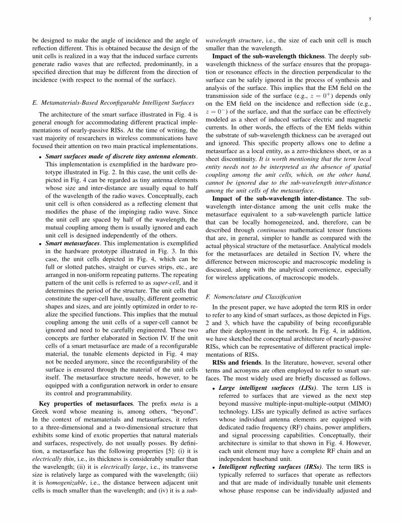
The architecture of the smart surface illustrated in Fig. 4 isgeneral enough for accommodating different practical imple-mentations of nearly-passive RISs. At the time of writing, thevast majority of researchers in wireless communications havefocused their attention on two main practical implementations.
• Smart surfaces made of discrete tiny antenna elements.This implementation is exemplified in the hardware pro-totype illustrated in Fig. 2. In this case, the unit cells de-picted in Fig. 4 can be regarded as tiny antenna elementswhose size and inter-distance are usually equal to halfof the wavelength of the radio waves. Conceptually, eachunit cell is often considered as a reflecting element thatmodifies the phase of the impinging radio wave. Sincethe unit cell are spaced by half of the wavelength, themutual coupling among them is usually ignored and eachunit cell is designed independently of the others.
• Smart metasurfaces. This implementation is exemplifiedin the hardware prototype illustrated in Fig. 3. In thiscase, the unit cells depicted in Fig. 4, which can befull or slotted patches, straight or curves strips, etc., arearranged in non-uniform repeating patterns. The repeatingpattern of the unit cells is referred to as super-cell, and itdetermines the period of the structure. The unit cells thatconstitute the super-cell have, usually, different geometricshapes and sizes, and are jointly optimized in order to re-alize the specified functions. This implies that the mutualcoupling among the unit cells of a super-cell cannot beignored and need to be carefully engineered. These twoconcepts are further elaborated in Section IV. If the unitcells of a smart metasurface are made of a reconfigurablematerial, the tunable elements depicted in Fig. 4 maynot be needed anymore, since the reconfigurability of thesurface is ensured through the material of the unit cellsitself. The metasurface structure needs, however, to beequipped with a configuration network in order to ensureits control and programmability.
Key properties of metasurfaces. The prefix meta is aGreek word whose meaning is, among others, “beyond”.In the context of metamaterials and metasurfaces, it refersto a three-dimensional and a two-dimensional structure thatexhibits some kind of exotic properties that natural materialsand surfaces, respectively, do not usually posses. By defini-tion, a metasurface has the following properties [5]: (i) it iselectrically thin, i.e., its thickness is considerably smaller thanthe wavelength; (ii) it is electrically large, i.e., its transversesize is relatively large as compared with the wavelength; (iii)it is homogenizable, i.e., the distance between adjacent unitcells is much smaller than the wavelength; and (iv) it is a sub-
wavelength structure, i.e., the size of each unit cell is muchsmaller than the wavelength.
Impact of the sub-wavelength thickness. The deeply sub-wavelength thickness of the surface ensures that the propaga-tion or resonance effects in the direction perpendicular to thesurface can be safely ignored in the process of synthesis andanalysis of the surface. This implies that the EM field on thetransmission side of the surface (e.g., z = 0+) depends onlyon the EM field on the incidence and reflection side (e.g.,z = 0−) of the surface, and that the surface can be effectivelymodeled as a sheet of induced surface electric and magneticcurrents. In other words, the effects of the EM fields withinthe substrate of sub-wavelength thickness can be averaged outand ignored. This specific property allows one to define ametasurface as a local entity, as a zero-thickness sheet, or as asheet discontinuity. It is worth mentioning that the term localentity needs not to be interpreted as the absence of spatialcoupling among the unit cells, which, on the other hand,cannot be ignored due to the sub-wavelength inter-distanceamong the unit cells of the metasurface.
Impact of the sub-wavelength inter-distance. The sub-wavelength inter-distance among the unit cells make themetasurface equivalent to a sub-wavelength particle latticethat can be locally homogeneized, and, therefore, can bedescribed through continuous mathematical tensor functionsthat are, in general, simpler to handle as compared with theactual physical structure of the metasurface. Analytical modelsfor the metasurfaces are detailed in Section IV, where thedifference between microscopic and macroscopic modeling isdiscussed, along with the analytical convenience, especiallyfor wireless applications, of macroscopic models.
F. Nomenclature and Classification
In the present paper, we have adopted the term RIS in orderto refer to any kind of smart surfaces, as those depicted in Figs.2 and 3, which have the capability of being reconfigurableafter their deployment in the network. In Fig. 4, in addition,we have sketched the conceptual architecture of nearly-passiveRISs, which can be representative of different practical imple-mentations of RISs.
RISs and friends. In the literature, however, several otherterms and acronyms are often employed to refer to smart sur-faces. The most widely used are briefly discussed as follows.• Large intelligent surfaces (LISs). The term LIS is
referred to surfaces that are viewed as the next stepbeyond massive multiple-input-multiple-output (MIMO)technology. LISs are typically defined as active surfaceswhose individual antenna elements are equipped withdedicated radio frequency (RF) chains, power amplifiers,and signal processing capabilities. Conceptually, theirarchitecture is similar to that shown in Fig. 4. However,each unit element may have a complete RF chain and anindependent baseband unit.
• Intelligent reflecting surfaces (IRSs). The term IRS istypically referred to surfaces that operate as reflectorsand that are made of individually tunable unit elementswhose phase response can be individually adjusted and

6
optimized for beamsteering, focusing, and other similarfunctions. Usually, the unit elements are assumed not tobe capable of amplifying the impinging radio waves, sothat only their phase response can be modified (not theiramplitude response).
• Digitally controllable scatterers (DCSs). The term DCSis the most similar to RIS, and it is typically employedto emphasize the possibility of controlling, in a digitalmanner, the behavior of objects and devices coated ormade of smart surfaces. In this case, the emphasis isput on the individual elements of the smart surface thatare viewed as local scatterers. DCSs are often made ofpassive elements that cannot amplify the received signals.If made of passive elements, the operation of DCSs isbased on the mutual coupling among the elements, and,hence, there exists a high spatial correlation among theunit cells depicted in Fig. 4.
• Software controllable surfaces (SCSs). The term SCS istypically employed when the emphasis is to be given tothe capability of the smart surfaces of being controlledand optimized by using software-defined networkingtechnologies. The term SCS is often employed whenthe unit elements of the smart surface are equippedwith a nano-communication network for enabling thecommunication among the unit cells. The smart surfaceis often equipped with low power sensors for environ-mental monitoring. The joint functionality of sensingand communication provides the smart surface with thecapability of performing simple local operations, thusmaking it more autonomous. This may, however, affectthe complexity and the power consumption of the entiresmart surface.
Formal classification of metasurfaces. A comprehensiveclassification of electromagnetic surfaces is available in [5,Fig. 1.10]. As far as smart surfaces with general (passive ornearly-passive) functions are concerned, which is the maininterest of the present paper, three main definitions can befound in [5, Fig. 1.10].
• Huygens’s surfaces. These are defined as smart surfacesthat manipulate the wavefront of incident radio waves inways that a secondary wavefront with the desired featurescan be obtained.
• Metasurfaces. These are defined as any artificial smartsurfaces with unconventional features.
• Reconfigurable surfaces and programmable metasur-faces. These are defined as smart surfaces that areequipped with active control devices, such as PIN diodes,micro electro mechanical systems (MEMS) switches, andvaractors, which are integrated into the smart surface inorder to provide real-time control of the surface proper-ties.
Based on the classification in [5, Fig. 1.10] and the namesusually adopted by researchers working in wireless communi-cations and networks, we evince that the acronym RIS can beconsidered to be the most suitable definition for the conceptualarchitecture of smart surface depicted in Fig. 4. This justifiesand corroborate the adoption of the term RIS in the present
Fig. 5: Electromagnetic-based elementary functions.
paper.
G. Macroscopic Functions of Reconfigurable Intelligent Sur-faces
Microscopic and macroscopic views. Based on the con-ceptual architecture depicted in Fig. 4, it is apparent that thefunctions that an RIS is capable of applying, at the macro-scopic level, to the impinging radio waves can be synthesizedby appropriately optimizing its operation at the microscopiclevel, i.e., by appropriately designing the unit cells and theconfiguration network made of low power electronic circuits.Simple examples on how to optimize the unit cells of a phase-gradient RIS in order to synthesize specified macroscopicfunctions are reported in Section IV.
Classification of macroscopic functions. In general terms,the functions realized by RISs for application to wirelessnetworks can be classified into two main categories.• EM-based design of RISs. These functions correspond
to elementary transformations of the radio waves that canbe directly specified at the EM level. Under this designparadigm, an RIS is optimized in order to realize somefundamental manipulations of the radio waves, whichmay be employed in wireless networks. According to thisdesign paradigm, communication engineers view RISs asblack boxes in which some parameters (knobs) can beoptimized for improving the network performance.
• Communication-based design of RISs. The functionsrealized by RISs under a communication-based designparadigm may not necessarily correspond to elemen-tary EM-based manipulations of the radio waves. For acommunication engineer, a fundamental question may,for example, be: What is the optimal design or useof an RIS in order to maximize the channel capacity?According to this design paradigm, the functions of RISsare not specified a priori, but they are the result of anoptimization problem and, therefore, may be differentdepending on the performance metric of interest. Forexample, RISs may be employed for realizing advancedmodulation and coding schemes by directly operating atthe EM level.
Some representative examples of these two design ap-proaches are given in the following two sub-sections.
1) EM-Based Design of RISs: In Fig. 5, we report someexamples of EM-based elementary functions that may be

7
Fig. 6: Communication-based (modulation and encoding) design ofreconfigurable intelligent surfaces.
applied by RISs and that may have useful applications in wire-less communications. These elementary functions are brieflydiscussed as follows.
• Reflection. This function consists of reflecting an imping-ing radio wave towards a specified direction that may notnecessarily coincide with the direction of incidence.
• Transmission/refraction. This function consists of re-fracting an impinging radio wave towards a specifieddirection that may not necessarily coincide with thedirection of incidence.
• Absorption. This function consists of designing a smartsurface that nulls, for a given incident radio wave, the cor-responding radio waves that are reflected and refracted.
• Focusing/beamforming. This function consists of focus-ing (i.e., concentrating the energy of) an impinging radiowave towards a specified location.
• Polarization. This function consists of modifying thepolarization of an incident radio wave (e.g., the imping-ing radio wave is transverse electric polarized and thereflected radio wave is transverse magnetic polarized).
• Collimation. This function is the complementary of fo-cusing.
• Splitting. This function consists of creating multiplereflected or refracted radio waves for a given incidentradio wave.
• Analog processing. This function consists of realizingmathematical operations directly at the EM level. Forexample, the radio wave refracted by a smart surfacemay be the first-order derivative or the integral of theimpinging radio wave.
2) Communication-Based Design of RISs: In addition tofunctions that directly pertain the manipulation of the imping-ing radio waves at the EM level, an RIS can be employedfor operations and applications that capitalize on EM-basedmanipulations of the radio waves but go beyond them. Forexample, a conceptual block diagram that depicts the appli-cation of RISs for implementing different types of transmitterdesigns is illustrated in Fig. 6. In this case, an RIS is viewed asan integral part of a transmitter. Other communication-baseddesigns, applications, and examples beyond transmit-relatedoperations (i.e., modulation and encoding) are described in
further text.
Metasurface-based transmitters. Figure 6 shows an RISthat is realized based on the conceptual architecture reported inFig. 4. From a communication-design perspective, a numberof super-cells (it can be even a single super-cell dependingon the function to be realized and the technology employed)are grouped together to form a macro-cell. A macro-cell canbe thought of as the atomic element to realize RIS-basedtransmitters. As a concrete example, one may think of a macro-cell as a physical structure that allows one to mimic a phaseshift keying (PSK) modulation. If an 8-PSK modulation isof interest, the macro-cell needs to be capable of realizingeight distinct phase shifts that correspond to those of a PSKmodulation employed by conventional modulators. In practice,this is realized by jointly designing the unit cells and the super-cells that constitute the macro-cell, as elaborated in SectionIV. The metasurface structure is illuminated by a feeder thatis located in close proximity of the RIS. The feeder emits onlyan un-modulated signal. The modulation is, in fact, realizeduniquely by the RIS through appropriate reflections of thesignal emitted by the feeder. To modulate data, the RIS iscontrolled by an encoder, which outputs two data streamsthat are employed for configuring the RIS. The first datastream is employed to set the reflection coefficient (R1, R2,...) of each macro-cell. Continuing with our example, eachreflection coefficient corresponds to one phase shift of an 8-PSK modulation. It may, however, be an arbitrary reflectioncoefficient that is chosen based on any design criteria. Thesecond data stream corresponds to conventional modulationsymbols. The two data streams are employed to simultaneouslycontrol the macro-cells that are activated for transmission ata given time instance (the macro-cells in blue color in Fig.6), and the modulated signals that they emit (the beams inpurple color in Fig. 6). The transmitter architecture sketchedin Fig. 6 is general enough to realize multiple practicalimplementations. Three examples are described as follows.
• RIS-based modulation. Let us assume that the datastream that corresponds to the state of the RIS con-trols only whether a macro-cell is either activated (ONstate) or not activated (OFF state). This implies thatthe reflection coefficient of each macro-cell is only oneor zero, respectively. Let us consider, in particular, thatonly a single macro-cell is activated at any transmissioninstance. Let us assume, in addition, that the data streamof the modulation symbols contains a single PSK symbol.Then, the RIS-based transmitter scheme in Fig. 6 canbe employed to realize a metasurface-based version ofspatial modulation and index modulation, in which thetransmitted data is encoded into the activated macro-cell and the PSK-modulated symbol [6], [7], [8], [9],[10], [11], [12]. This specific implementation of spatialmodulation is attractive because of the large numberof macro-cells that may be deployed on an RIS, and,therefore, the large number of bits that can be modulatedonto the ON-OFF states of the macro-cells. For example,the RIS prototype in Fig. 2 is made of 3,720 inexpensiveindividually tunable antennas and the RIS prototype in

8
[13] is made of 10,000 unit cells. This implies that tensof bits per channel use may be modulated by usingthis approach, while using a single feeder. Ultimately,however, the achievable rate depends on the speed atwhich the macro-cells can be configured.
• RIS-based multi-stream transmitter. Let us assume thatthe data stream that corresponds to the state of the RIScontrols the reflection coefficient of each macro-cell so asto mimic a PSK modulation. Let us assume, in addition,that the data stream of the modulation symbols is notenabled, i.e., the RIS is not fed with any bits through thiscontrol signal. Then, the RIS-based transmitter schemein Fig. 6 can be employed to realize a metasurface-based version of multi-antenna spatial multiplexing, inwhich the number of data streams that are simultaneouslytransmitted depend on the number of macro-cells thatare activated at any transmission instance. If all themacro-cells are activated simultaneously, the RIS-basedtransmitter scheme in Fig. 6 is capable of emitting twelvedata streams simultaneously. In general, the larger thenumber of data streams is, the higher the complexityof the control and configuration network of the RIS is.Examples of existing prototypes for RIS-based multi-stream transmitters can be found in [14], [15], [16], [17],[18]. This specific implementation of spatial multiplexingis attractive because multiple data streams are transmittedsimultaneously, while employing a single feeder, i.e., asingle power amplifier and a single RF chain.
• RIS-based encoding. Let us assume that the data streamthat corresponds to the state of the RIS controls thereflection coefficient of each macro-cell so as to mimic adiscrete set of values. For generality, let us consider thatall the macro-cells are activated at the same time. Letus assume, in addition, that the data stream of the mod-ulation symbols contains a single symbol that belongsto a given constellation diagram. Then, the RIS-basedtransmitter scheme in Fig. 6 can be employed to realize atransmitter that jointly encodes data onto the modulationsymbol x and the set of reflection coefficients R1, R2, ...of the macro-cells. This implementation has recently beenstudied, from an information-theoretic standpoint, in [19].Therein, it is proved that jointly encoding information onthe modulation symbol and the configuration of an RIS,as a function of the channel state information, provides abetter channel capacity as compared with the baselinescheme in which the configuration of the RIS is notexploited for data modulation. This result is importantbecause it proves that maximizing the received poweris not necessarily optimal from an information-theoreticpoint of view.
Several other transmitter designs may be realized, based onthese three examples, which capitalize on the possibility ofshaping the radio waves emitted by an RIS through a simpleRF feeder and an encoder that controls the configurationnetwork sketched in Fig. 4.
H. Distinctive Peculiarities of Reconfigurable Intelligent Sur-faces
RISs vs. competing technologies. As mentioned in previ-ous text, some instances of RISs with active unit elements(usually referred to as LISs) are often viewed as the nextstep beyond massive MIMO. Similarly, nearly-passive RISthat are implemented by using surfaces made of discrete tinyantenna elements with inter-distances equal to half of thewavelength are often compared to multi-antenna relays withno power amplification capabilities or to reflectarrays that areilluminated by a feeder that is not located in close proximityof the surface. Comparative studies on the differences andsimilarities between RISs, massive MIMO, relays, and othertechnologies are reported and discussed in Section V.
The main reasons that make RISs different. In this sub-section, we are interested in elaborating on some fundamentalaspects that, in our opinion, make nearly-passive RISs differentfrom currently available technologies, and that, at the sametime, offer opportunities for innovative solutions that havenever been in the mainstream of wireless communicationsbefore. More specifically, the following aspects are consideredto be distinctive and peculiar features of nearly-passive RISs.
• Unique design constraints. The nearly-passive nature ofRISs introduces challenging design constraints, e.g., theimpossibility of performing channel estimation directlyon the smart surface and on the way that the radio wavescan be manipulated by the smart surface.
• Communication without new waves. The nearly-passivenature of RISs offers unique opportunities for redefiningthe notion of communication, in which information canbe exchanged without producing new EM signals butby recycling existing radio waves. This may be highlybeneficial for reducing the EM pollution and for decreas-ing the level of EM exposure of human beings, whichis usually increased by deploying additional networkinfrastructure and by using more spectrum. This maybe extremely relevant for the successful deployment ofwireless technologies in EM-sensitive environments (e.g.,in hospitals).
• Sustainable wireless by design. The use of innovativeeco-friendly metamaterials in order to realize and man-ufacture nearly-passive RISs opens the possibility forbuilding future wireless networks that are sustainable bydesign. The materials that are employed to realize thesmart surfaces can be chosen to be cost-effective, to havea light environmental footprint, and to be highly recy-clable. This, in turn, may impose some design constraintson the functions that the RISs may be able to realize.
• Beyond the far-field regime. The RISs may be madeof geometrically large surfaces of the order of a fewsquare meters. Figure 2 reports an example of smartsurface whose size is of the order of six square meters.A recent prototype of metasurface reported in [13] hasa size of one square meter and operates at 10.5 GHz.If one assumes that the far-field of the smart surfacecan be defined in a similar manner as for conventionalantenna arrays, the far-field propagation regime for such

9
Fig. 7: Fraunhofer’s distance at sub-6 GHz (a) and millimeter-wave(b) frequencies (D is fixed).
Fig. 8: Fraunhofer’s distance at sub-6 GHz (a) and millimeter-wave(b) frequencies (D depends on λ).
an RIS may start at tens of meters far away from thesmart surface. This implies that such a smart surface mayoperate in the near-field in some relevant scenarios, e.g.,in indoor environments. The use of geometrically largeRISs opens, therefore, the possibility of building newwireless networks that operate in the near-field regime,which is not a conventional design assumption in wirelesscommunications. As an illustrative example, Figs. 7 and 8reports the Fraunhofer distance that is usually employedfor identifying the limit between the radiative near-fieldand the far-field, i.e., dF = 2D2/λ, where D is thelargest dimension of the RIS under analysis and λ isthe wavelength of the radio wave. It is apparent that,depending on the setup, the radiative near-field operatingregime may be sufficiently large for typical indoor andmobile outdoor communication systems.
• Dense deployment of scatterers. If RISs are made ofsmart metasurfaces, they comprise a large number of sub-wavelength unit cells. Such envisioned sub-wavelength
dense deployments of tiny sub-wavelength scattering ele-ments is not commonly employed in wireless communi-cations, where the mutual coupling among the radiatingelements is often avoided by design, i.e., by ensuringthat the scattering elements are sufficient distant fromeach other. This paves the way for developing newsignal and propagation models that may affect the ul-timate performance limits of wireless networks, and forintroducing new design paradigms according to whichcommunication systems and networks are engineered tobe mutual-coupling-aware and mutual-coupling-robust.
• High focusing capabilities in the radiative near-field. Asillustrated in Figs. 7 and 8, RISs may have a sufficientlylarge size and the operating wavelength may be suffi-ciently small that the radiative near-field region may notbe ignored in typical wireless applications. This operatingregime is not usual in wireless communications, and maypave the way for realizing near-field focused RISs thathighly concentrate the EM power in small spot regions[20]. This high focusing capability may have multipleapplications, e.g., (i) for enabling interference-free com-munication in areas with high densities of devices; (ii)for making possible the precise radio localization of usersand mapping of environments; and (iii) for recharging thebatteries of low power devices via wireless power transfermethods.
I. Beyond Planar Reconfigurable Intelligent Surfaces: Confor-mal Smart Surfaces
RISs are not necessarily planar structures. We close thissection by mentioning that the present paper is focused onRISs that are made of smart surfaces that are planar. Thisassumption originates from the ease of deployment of suchsurfaces on, e.g., the internal walls of indoor environments, theexternal facades of buildings, and the glasses of windows. Thesame principles apply, however, to free-form conformal bi-dimensional smart surfaces, which are not necessarily planar.These structures may have several applications in wirelesscommunications, e.g., for coating objects that are not planarand for shaping the radio waves in ways that planar smartsurfaces many not be capable of.
III. SMART RADIO ENVIRONMENTS
Designing wireless networks today: The environment isfixed by nature. Current methods to design wireless networksusually rely on the optimization of the so-called end-pointsof communication links, e.g., transmitters and receivers. Overthe last decades, therefore, many advanced techniques havebeen proposed for improving the performance of wirelessnetworks, which encompass advanced modulation/encodingschemes and protocols based on using, e.g., multiple antennasat the transmitters, powerful transmission and retransmissionprotocols, and robust demodulation and decoding methodsat the receivers. The wireless environment has, on the otherhand, been conventionally modeled as an exogenous entity thatcannot be controlled but can only be adapted to. Accordingto this design paradigm, communication engineers usually

10
design the transmitters, the receivers, and the transmissionprotocols based on the specific properties of the wirelesschannels and in order to achieve the desired performance.For example, transmitters equipped with multiple radiatingelements may be configured differently as a function of thespecific characteristics of the wireless channel where theyoperate, in order to achieve the desired trade-off in terms ofspatial multiplexing, spatial diversity, and beamforming gains.
SREs: The environment is generated by nature but isprogrammable by design. The overarching paradigm thatcharacterizes the design of current wireless networks consists,therefore, of pre-processing the signals at the transmittersand/or post-processing the signals at the receivers, in order tocompensate the effect of the wireless channel and/or in orderto capitalize on specific features and characteristics of thewireless channel. RISs provide wireless researchers with moreopportunities for designing and optimizing wireless networks,which are built upon a different role played by the wirelessenvironment. RISs are, in fact, capable of shaping the radiowaves that impinge upon them, after the radio waves areemitted by the transmitters and before they are observed bythe receivers, in ways that the wireless environment can becustomized, in principle as one desires, in order to fulfillspecific system requirements. The wireless environment is,therefore, not treated as a random uncontrollable entity, butas part of the network design parameters that are subject tooptimization for supporting diverse performance metrics andquality of service requirements.
Revisiting communication-theoretic models. The conceptof SREs introduces, therefore, a new communication-theoreticview of wireless systems and offers new opportunities foroptimization. In Fig. 9, the conceptual block diagram of a con-ventional point-to-point communication system and the corre-sponding block diagram under a SRE-based framework areillustrated. Under the conventional communication-theoreticframework, the system is modeled through transition prob-abilities that are not considered to be optimization variables.Under the SRE-based communication-theoretic framework, onthe other hand, the system is modeled through transition prob-abilities that can be customized, thanks to the deployment ofRISs throughout the environment and thanks to the possibilityof controlling and programming the functions that RISs applyto the impinging radio waves. Therefore, the system modelitself becomes an optimization variable, which can be jointlyoptimized with the transmitter and the receiver: Rather thanoptimizing the input signal for a given system model, one cannow jointly optimize the input signal and the system.
SREs with and without joint encoding and modulationat the transmitter and at the RIS. In Fig. 9, in particular,three system models are illustrated. The first communication-theoretic model is referred to a conventional radio environmentin which, via a feedback channel that provides the encoderwith channel state information, the transmitter and receiver arejointly optimized, e.g., by designing appropriate transmit andreceive channel-aware vectors. The second communication-theoretic model is referred to an RIS-empowered SRE inwhich the feedback channels from the receiver and the en-vironment (e.g., the RIS) are exploited for optimizing the
Fig. 9: Communication-theoretic models for radio environments andsmart radio environments (with and without joint encoding).
setup (i.e., configuration, state, or action) of the RIS besidesthe transmit and receive channel-aware vectors. In this case,therefore, the transition probabilities that describe the wirelessenvironment can be customized by appropriately optimiz-ing the state of the RIS. These first two communication-theoretic models are analyzed and compared in [21]. Thethird communication-theoretic model is referred to an RIS-empowered SRE in which the state of the RIS is employedfor customizing the wireless environment while at the sametime encoding information jointly with the transmitter. In thissetup, in particular, the transition probabilities of the wirelessenvironment depend on both the state of the RIS, which affectsthe wireless channel, and the data s encoded by the transmitteron the state of the RIS. This setup is analyzed in [19], whereit is proved that performing joint transmitter-RIS encodingyields, in general, a better channel capacity.
Communication model with state-dependent channels.From an information-theoretic standpoint, broadly speaking,the conventional block diagram in Fig. 9 is described by theconditional probability law of the channel output given thechannel input. For example, a binary symmetric channel isa model for describing the communication of binary datain which the noise may cause random bit-flips with a fixedprobability. In the context of SREs, the conditional probabilitylaw of the channel output given the channel input can becustomized by using RISs. The wireless environment can beprogrammed to evolve through multiple states (or configura-

11
tions) that depend on how the RISs shape the impinging radiowaves. The possibility of controlling the possible states ofoperation of the wireless environment jointly with the oper-ation of the transmitter and the receiver offers opportunitiesfor enhancing the overall communication performance. The re-sulting communication-theoretic model well fits, therefore, thetransmission of information through state-dependent wirelessenvironments (or simply channels) that are generated by naturebut that are controlled and affected by the communicationsystem. The block diagram in Fig. 9 illustrates the case studyin which the transmitter takes actions (i.e., it configures theoperation of the RISs distributed throughout the environment)that affect the formation of the states of the environment.In general, the specific state of the wireless environmentcan be controlled by the transmitter, the receiver, or by anexternal controller that oversees the operation of portions orthe entire network. In general, in fact, the operating state of thewireless environment depends on the configuration of all theRISs distributed throughout it, which can be jointly optimizedfor achieving superior performance. The block diagram ofSREs well fits, therefore, a communication model with state-dependent channels, whose states are directly controlled by thecommunication system rather than being generated and beingdependent only by nature [22].
Overcoming fundamental limitations of wireless net-works design. The possibility of creating wireless systemswith state-dependent channels, which are generated by naturebut are controlled by communication designers, opens newopportunities for overcoming some fundamental limitationsin designing current wireless networks. Four of them are thefollowing.
• The ultimate performance limits of wireless networksmay not have been reached yet. Recent research workshave proved that by jointly optimizing the transmitter, thereceiver, and the environment, the channel capacity ofa point-to-point wireless communication system can befurther improved [19]. In particular, the channel capacitycan be increased by capitalizing on RISs as a means forencoding and modulating additional information besidesthe transmitters.
• Customizing and controlling the wireless environmentmay open new opportunities for network optimization. Insome application scenarios, the transmitters and receiversmay not be equipped with multiple antenna-elementsbecause of the challenges that their practical realizationentail. For example: (i) devices such as sensors andhandhelds are usually small in size, and multiple antennascannot be accommodated; (ii) connecting each antenna toan independent RF chain and transmit/receive circuitryincreases the cost and power consumption; and (iii)multiple-antenna structures are often bulky and are noteasy to deploy even at the base stations. Recent resultshave shown that these challenges can be overcome bycapitalizing on RISs and by moving the operations thatare typically executed by multiple-antenna transmittersdirectly to the radio environment [3]. An example is theRFocus prototype illustrated in Fig. 2.
• The radio waves may be used more efficiently. Whenreflected or refracted by an object, for example, theenergy of the impinging radio waves is scattered towardsunwanted directions, thus reducing the efficiency of uti-lization of the emitted power. The possibly large sizeof RISs and their fine ability of controlling the radiowave thanks to their sub-wavelength structure offer theopportunity for realizing smart surfaces that are capableof increasing, in the radiative near-field of the surface,the EM power density in spot regions of very limitedsize [20]. Therefore, very high focusing capabilities maybe obtained by focusing the energy only where it isneeded and by avoiding to create interference in unwantedlocations.
• The spatial capacity density may be increased. Recentresults in [23] have proved that RISs offer opportuni-ties for increasing the available degrees of freedom ofwireless communications, by creating large numbers oforthogonal communication links per square meter. Thesecommunication channels, which are orthogonal at the EMlevel, can be employed to simplify the wireless accessin multiple-access systems, by realizing communicationfunctionalities directly at the EM level, i.e., the “layer-0” of the protocol stack. Based on these findings, RISsmay be employed for achieving spatial multiplexing gainsin wireless environments in which conventional multiple-antenna schemes cannot, e.g., in environments withouta sufficiently rich multipath scattering. These resultscan find applications in scenarios with high densities ofdevices that can be simultaneously served over the EM-orthogonal channels, thus offering, in principle, very highcapacity densities.
SREs: Centralized vs. distributed. RIS-empowered SREsoffer, therefore, several opportunities for improving the perfor-mance of wireless networks and, possibly, for further movingahead the fundamental limits of wireless communications.RISs can turn wireless networks into SREs in multiple ways.Broadly speaking, one could think of wireless networks inwhich users and devices interact with the environment anytimethat they are in close vicinity of a smart surface, so as to eitherenhance the communication performance or to reduce theutilization of resources. SREs can be realized in a centralized,distributed, or hybrid manner.
• Centralized implementation. In this case, it is assumedthat a central controller exists and that it coordinatesthe activity of a network neighborhood. In a central-ized implementation, RISs can be realized as simpleas possible, since they are not required to be equippedwith significant on-board, sensing, signal processing, andcommunication capabilities. RISs could be realized basedon nearly-passive implementations, which need to be onlyable to receive the configuration signals and to set theconfiguration network depicted in Fig. 4 accordingly.In a centralized implementation, however, the centralcontroller needs to be able to gather the channel stateinformation without relying on any on-board sensing andsignal processing capabilities at the RISs. Therefore, ap-

12
malicioususer
RIS-nulled
reflection
useruser multi-antennauser
reliable
non-
line-of-
sight
RIS-nulledinterference
high-rankcombinedchannel
powertransfer
Fig. 10: Potential applications of reconfigurable intelligent surfacesin smart radio environments.
propriate protocols to obtain this information are needed,and the associated channel estimation overhead needs tobe taken into account for the optimal design and operationof RISs [21].
• Distributed implementation. In this case, a central con-troller is not necessarily needed. RISs need, however, tohave the required functionalities for autonomously iden-tifying the optimal function to apply based on the envi-ronmental state information and on the network topology,e.g., the locations of users and access points. It may bedifficult, as a consequence, to employ nearly-passive RISsin a distributed implementation, since they need to be ableto sense the channel, to extract the necessary channelstate information, and to communicate this informationthroughout the structure of the smart surface. This maybe realized by employing low power sensors that arepossibly equipped with energy harvesting capabilitiesand nano-communication protocols for enabling the self-configuration of the unit cells. The higher implementationcomplexity of the RISs is the price to pay for dispensingSREs from the need of a central controller and theassociated signaling and channel estimation overhead.
• Hybrid implementation. This can be viewed as an inter-mediate network realization of SREs, where RISs withdifferent capabilities may be deployed in the network inorder to strike a balance between (i) the higher imple-mentation complexity and power consumption of RISs indistributed implementations, and (ii) the higher channelestimation and signaling overhead that are necessary tofeed the central controller and to report the environmentalinformation to other network elements.
Potential applications and scenarios. In the next two sub-sections, we report some applications of RISs and some sce-narios for SREs. For ease of representation, the illustrations aregiven without explicitly referring to a centralized, distributed,or hybrid implementation. In principle, the three approachescan be realized with their advantages and limitations.
A. Potential Applications of Reconfigurable Intelligent Sur-faces in Smart Radio Environments
In this section, we briefly describe some potential appli-cations of RISs. Some of them are illustrated in Fig. 10 asexamples.
• Coverage enhancement. An RIS can be configured inorder to create configurable non-line-of-sight links indead-zone (or low coverage) areas in which line-of-sightcommunication is not possible or it is not sufficient.
• Interference suppression. An RIS can be configured tosteer signals towards specified directions or locations notonly for enhancing the signal quality, but for suppressingunwanted signals that may interfere with other commu-nication systems.
• Security enhancement. This application is similar tointerference suppression, with the difference that an RIScan be configured to worsen the signal detected byeavesdroppers by either creating destructive interferenceor by altering the reflection of signals towards locationsnot occupied by unauthorized users.
• Channel rank enhancement. The spatial multiplexinggain that can be achieve in multiple-antenna systemsdepends on how well conditioned the channel matrix is.An RIS can be appropriately configured in order shapethe wireless environment in a way that the channel matrixhas a high rank and a condition number close to one, soas to increase the channel capacity.
• Focusing enhancement. An RIS of large geometric size(in further text referred to as electrically large RIS)can operate in the radiative near-field at transmissiondistances up to a few tens of meters, as illustrated inFigs. 7 and 8. Therefore, the scattered radio waves canbe focused towards spatial spots of narrow size, so asto capillary serve dense deployments of users withoutcreating mutual interference.
• Radio localization enhancement. The high focusing ca-pabilities of RISs of large geometric size can be capital-ized for finely estimating the location of mobile terminalsand devices, so as to support high-precision ranging, radiolocalization, and mapping applications.
• Information and power transfer. The high focusing ca-pabilities of RISs of large geometric size can be exploitedfor concentrating the energy towards tiny and energy-autonomous sensor nodes, so that the radio waves can beemployed, simultaneously, to recharge the sensors and totransmit information.
• Ambient backscattering. Consider a low power sensornode that is embedded into a smart surface for environ-mental monitoring. Any time that a radio wave impingesupon the smart surface, the RIS may be configured tomodulate/encode the data sensed by the low power sensorinto the scattered signal, e.g., by transmitting the senseddata through the time-domain scattered waveform (seeFig. 5). This enables low power sensors to piggybackinformation into ambient radio waves without creatingnew radio signals and, de facto, by recycling existingradio waves for communication [24], [25].
Other applications, such as RIS-based modulation, RIS-based multi-stream transmission, and RIS-based encoding aredepicted in Fig. 6 and are described in Section II-G.

13
Fig. 11: Potential scenarios of smart radio environments: A world of nearly-passive reconfigurable intelligent surfaces.
B. Potential Scenarios of Smart Radio Environments
Several potential scenarios can benefit from the concept ofSREs. Some promising case studies are briefly discussed asfollows, and a sub-set of them is illustrated in Fig. 11.• Smart cities. In cities, the facades of large buildings may
be coated with RISs of large geometric size. This offersopportunities for, e.g., enhancing the coverage, increasingthe spectral efficiency, and reducing the exposure tothe EM radiation in outdoor environments, since thedeployment of RISs may reduce the amount of networkinfrastructure (e.g., based stations) to deploy.
• Smart homes. In homes, the interior walls may be coatedwith RISs of different sizes for enhancing the localconnectivity of several kinds of handlers (mobile phones,tablets, etc.) and other devices that rely on wirelessconnectivity for operation.
• Smart buildings. In buildings, large windows may bemade of special glasses that can selectively enable indoor-to-outdoor and outdoor-to-indoor connectivity. This maybe suitable for enhancing the connectivity at high trans-mission frequencies.
• Smart factories. In factories, the presence of large metal-lic objects usually result in harsh wireless propagationenvironments. RISs constitute a suitable approach forturning strong reflections of radio waves into a benefitfor enhancing the coverage and the transmission rate.
• Smart hospitals. Hospitals are EM-sensitive environ-ments, where the intensity of the radio waves needs tobe kept at a low level. RISs can be employed in order toenhance the local coverage without the need of increasing
the transmitted power.• Smart university campuses. In university campuses, large
buildings, offices, classrooms, etc. can be coated withRISs that can offer the desired high-speed connectivitywithout the need of installing several access points.
• Smart undergrounds. In undergrounds, the coverage ofwireless signals is usually negatively affected by thecomplex topology of the radio environment. RISs can bedeployed in, e.g., ceilings, billboards, and walls, so as toprovide the necessary connectivity to a large number ofusers simultaneously.
• Smart train stations. In train stations, several usersmay be waiting on the platforms before the arrival oftrains. RISs can be deployed for illuminating areas ofthe platforms in order to enhance the received signals ofindividual users or clusters of users.
• Smart airports. In airports, large numbers of users maymake take different directions when disembarking fromairplanes. RISs can be employed for steering differentbeams towards different hallways, so as to enhance thequality of the received signals. Also, RISs may be used toenhance the signals in high-speed download areas, e.g.,Internet areas in close proximity of the gates.
• Smart billboards. Billboards may constitute a promisingapproach for deploying RISs of different geometric size ina simple and effective manner, both in indoor and outdoorenvironments.
• Smart glasses. In urban areas, large portions of thesurface of buildings are made of glass. The example inFig. 3 shows that smart glasses realized with metasurfaces

14
can be built and can effectively control the propagationof radio waves. These smart glasses can be employed forenhancing the coverage in, e.g., dead-zone areas.
• Smart clothing. Clothing can be realized with metama-terials and several embedded smart sensors in order tocreate wearable body networks for monitoring the healthof people.
• Smart cars. The glasses and the roof of cars may becoated with RISs that can provide reliable communica-tions within the car itself, as well as can serve as movingnearly-passive relays for enhancing vehicle-to-vehicle andvehicle-to-infrastructure communications.
• Smart trains. The interior of trains may be coated withRISs in order to provide a better signal coverage and toreduce the levels of EM radiation and the exposure ofpassengers to EM fields.
• Smart airplanes. The overhead bins inside airplanes maybe coated with RISs that may provide high-speed Internetto passengers while reducing their EM field exposureand/or decreasing the power consumption.
Aesthetically-friendly environments. In our everyday life,in conclusion, RISs may offer countless opportunities torealize SREs. One of the advantages of metasurfaces is thatthey can be built, e.g., by using the smart glass in Fig. 3, so asnot to interfere aesthetically or physically with the surroundingenvironment or people line-of-sight, making them ideal foruse within buildings and on vehicles or billboards. RISs canbe deployed every time and in locations that are not suitedfor the installation of base stations, such as built-up areas orin indoor areas in which the reception of signals needs to beblocked selectively (e.g., in high-security areas).
C. On the Role of Machine Learning in Smart Radio Environ-ments
Awareness of the surrounding environment. In order torealize a “truly smart” SRE, it is not sufficient to be able tocustomize the radio environment as desired. It is necessary, inaddition, to optimally configure the most appropriate operationof spatially distributed RISs, in order to provide the users withthe best communication performance and quality of experi-ence. RISs necessitate, therefore, full awareness of the com-plex and non-stationary surrounding environments in whichthey are deployed. This requires efficient and on-demandnetwork intelligence to cope with complex deployment plan-ning, real-time programmability for optimization, and dynamiccontrol for service provisioning. Machine learning and ar-tificial intelligence (AI) may constitute efficient approachesfor leveraging the potential benefits of RIS-empowered SREs,especially because the computational complexity of deploying,programming, and controlling SREs rises significantly with theincrease of the network-to-infrastructure and user-to-networkinteractions.
AI is the answer. Therefore, machine learning computa-tional methods may be suitable enablers for optimizing andoperating SREs. AI-enabled machines, in particular, can bedesigned to perform “intelligent” tasks without being pro-grammed to accomplish any single (repetitive) task, but by
adapting themselves to different environments. To this end, AIprovides methods for designing networks that autonomouslyinteract with the environment, in ways that humans considerintelligent, including the characteristics of human cognitiveabilities, i.e., planning, perceiving, reasoning, learning, andproblem solving. AI defines general frameworks for knowl-edge manipulation (building new knowledge and exploit-ing already gained knowledge) through perception, reasoning(specifying what is to be done, but not how) and acting. SREsmay be designed by leveraging and capitalizing on AI-basedreasoning, acting, planning, and learning. Further informationon the application of machine learning and AI to SREs canbe found in [26], [27], [28].
IV. RISS IN WIRELESS NETWORKS – A MACROSCOPICHOMOGENIZED COMMUNICATION-THEORETIC APPROACH
Communication-theoretic modeling and analysis. Thissection introduces analytical methods and methodologies formodeling RISs that are made of metasurfaces, and for com-puting the EM field scattered by metasurfaces. To this end,this section is split in two main parts.• Modeling metasurfaces. In the first sub-section, we
move from a physics-based microscopic description of ametasurface and introduce a macroscopic representationfor it, which is shown to be suitable for application inwireless communications. In particular, a metasurface isrepresented by using continuous inhomogeneous func-tions that allow one to describe the signal transformationsapplied by a metasurface directly on the EM fields. Theuse of continuous functions is allowed, even though the(conceptual) physical structure of the metasurface in Fig.4 is made of discrete unit cells (scatterers), becausea metasurface can be homogenized. Therefore, its EMproperties can be completely described through macro-scopic parameters, in analogy with volumetric materialsthat can be completely described through their effectivepermittivity and permeability parameters. The homoge-nized macroscopic representation of a metasurface basedon continuous inhomogeneous functions is shown to beuseful for the synthesis (i.e., to design a metasurfacebased on specified/desired signal transformations) and forthe analysis (i.e., to compute the reflected and refractedEM fields in close proximity of a metasurface, for agiven incident EM field and the physical structure of themetasurface) of RISs.
• Modeling radio waves. In the second sub-section, weconsider the interaction between the radio waves emittedby a source and a metasurface. We introduce an analyticalapproach, based on the theory of diffraction and theHuygens-Fresnel principle, which allows us to computethe EM field at any point of a given volume that containsthe metasurface. In particular, we show that the EM fieldat any point of the volume can be formulated in terms ofthe EM field in close proximity of the metasurface (i.e.,on its surface), as specified in the first sub-section.
Modeling radio waves in the presence of metasurfaces.It is apparent, therefore, that the next two sub-sections are
15
intertwined, and are both needed for designing, analyzing,and optimizing RISs in wireless networks. In particular, thefirst sub-section introduces the analytical tools for modelingthe discontinuity of the EM field at the incidence-reflectionside and refraction side of a metasurface. The second sub-section, on the other hand, departs from the latter surfaceEM fields and introduces the analytical tools for calculatingthe EM field at any point of a volume, which, for example,allows one to unveil how the EM fields scale as a function ofthe transmission distance, the size of the metasurface, and thephysical structure of the metasurface.
A. Surface ElectromagneticsBefore introducing the details of the concept of homoge-
nized modeling for metasurfaces, we feel important to brieflyacquaint the readership of the present paper with the researchdiscipline of surface electromagnetics (SEM), which is theenabling tool for modeling, analyzing, and synthesizing meta-surfaces. The content of this sub-section is, in particular, basedon the textbook [5], to which interested readers are referredfor further information.
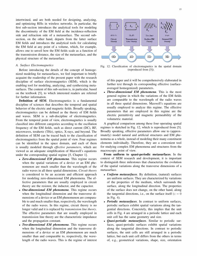
Definition of SEM. Electromagnetics is a fundamentaldiscipline of sciences that describes the temporal and spatialbehavior of the electric and magnetic fields. Broadly speaking,electromagnetics can be defined as the theory of EM fieldsand waves. SEM is a sub-discipline of electromagnetics.From the temporal point of view, electromagnetics is usuallyclassified into different categories according to the oscillationfrequency of the EM fields, such as direct current (DC), RF,microwaves, terahertz (THz), optics, X-rays, and beyond. Thedefinition of SEM can be traced back to the classification ofelectromagnetics from the spatial point of view. Four regimescan be identified in the space domain, and each of themis usually modeled through effective parameters, which areviewed as an adequate simplification of Maxwell’s equationsunder the corresponding spatial regime [5, Chapter 1].• Zero-dimensional EM phenomena. This regime occurs
when the spatial variations of a device or an EM phe-nomenon are much smaller than the wavelength of theradio waves in all three spatial dimensions. Circuit theoryis considered to be an accurate and efficient approachfor modeling zero-dimensional EM phenomena. The ef-fective parameters that are usually employed in circuittheory are the resistor, the inductor, and the capacitor.
• One-dimensional EM phenomena. This regime occurswhen the longitudinal dimension and the transverse di-mensions of a device or an EM phenomenon are compara-ble to and much smaller than, respectively, the wavelengthof the radio waves. In this regime, circuit theory is nolonger valid and it is replaced by transmission line theory.The effective parameters that are usually employed intransmission line theory are the characteristic impedanceand the propagation constant.
• Two-dimensional EM phenomena. This regime occurswhen the longitudinal dimension and the transverse di-mensions of a device or an EM phenomenon are muchsmaller than and comparable to, respectively, the wave-length of the radio waves. This is the regime of interest
Fig. 12: Classification of electromagnetics in the spatial domain(reproduced from [5]).
of this paper and it will be comprehensively elaborated infurther text through its corresponding effective (surface-averaged homogenized) parameters.
• Three-dimensional EM phenomena. This is the mostgeneral regime in which the variations of the EM fieldsare comparable to the wavelength of the radio wavesin all three spatial dimensions. Maxwell’s equations areusually employed to analyze this regime. The effectiveparameters that are employed in this regime are theelectric permittivity and magnetic permeability of thevolumetric material.
A graphical comparison among these four operating spatialregimes is sketched in Fig. 12, which is reproduced from [5].Broadly speaking, effective parameters allow one to (approx-imately) model natural and artificial structures and EM phe-nomena as a whole, instead of modeling their many constituentelements individually. Therefore, they are a convenient toolfor studying complex EM phenomena and structures from themacroscopic point of view.
From uniform to quasi-periodic metasurfaces. In thecontext of SEM research and development, it is importantto distinguish three milestones that characterize the evolutionof the spatial variations along the transverse dimensions of ametasurface.• Uniform metasurfaces. By definition, (natural) surfaces
are uniform surfaces. They are characterized by variationsof the properties of the medium, which surrounds thesurface, along the longitudinal direction. The propertiesof the surface does not change, on the other hand, alongthe tangential directions, i.e., on the surface itself (z = 0in Fig. 4).
• Periodic metasurfaces. In contrast to uniform surfaces,periodic surfaces exhibit spatial variations along the tan-gential directions. Concretely, this implies that the unitcells in Fig. 4 are arranged in a periodic lattice and eachunit cell has the same geometry and size.
• Quasi-periodic metasurfaces. Similar to periodic sur-faces, quasi-periodic surfaces exhibit spatial variationsalong the tangential directions. In contrast to periodicsurfaces, the unit cells are still arranged in a periodiclattice, but each unit cell differs from the others in termsof, e.g., geometrical variations, shape, size, orientation

16
Fig. 13: The road to quasi-periodic metasurfaces (reproduced from[5]).
angle, etc. This is the configuration reported in Fig. 4.Similarity with modulated signals. The evolution from the
uniform, periodic, and quasi-periodic feature of the transversedimensions of a metasurface can be considered to be equiva-lent to the evolution of the analysis of signals in circuits, i.e.,from DC signals, to alternate current (AC) signals, and even-tually to modulated signals. A graphical comparison amongthe uniform, periodic, and quasi-periodic design structures isreported in Fig. 13, which is reproduced from [5]. The quasi-periodic structure of the smart surface in Fig. 4 is, therefore,apparent and completely justified.
Naive interpretation of quasi-periodic metasurfaces. Thecore concept behind the development and widespread utiliza-tion of quasi-periodic metasurfaces lies in their more versatile,unprecedented, and exotic capabilities of manipulating EMwaves. Naively, the operating principle of quasi-periodic meta-surfaces can be thought of as a two-step manipulation of theradio waves: (i) first, each unit cell manipulates the incidentradio waves locally and individually; and (ii) next, the spatialdistribution of the obtained wave manipulations collectivelyalters the wavefront of the incident radio waves, leading toextraordinary EM responses and transformations of EM fields.
B. Theoretical Foundation of Surface Electromagnetics
Volumetric (bulk) vs. surface effective parameters. Thebehavior and the properties of metamaterials, which are volu-metric engineered structures, are determined by the electricand magnetic properties of its constituent scatterers. Thetraditional and most convenient approach for modeling meta-materials is the effective medium theory (EMT). EMT pertainsto the theoretical and analytical models and methods fordescribing the macroscopic properties of composite materials.At the constituent level, composite materials can be viewedas a micro-inhomogeneous medium. The precise calculationand analysis of the many elements that constitute a compositematerial is a nearly impossible task. EMT provides one witha set of effective parameters that describe, approximately, acomposite material as a whole. These parameters are, e.g.,the effective electric permittivity and the effective magneticpermeability of the composite material, which are obtained byaveraging (over a small volume) the response of the multipleconstituents that compose the material. More precisely, thenotions of electric permittivity and magnetic permeability
Fig. 14: Illustration of the surface equivalent theorem applied tothe scattering of volumetric electromagnetic sources (a) and to the
concept of metamaterials (b) (reproduced from [5]).
result from the volumetric averaging of microscopic electricand magnetic currents over volumes that are small compared tothe wavelength of the radio waves. A similar bulk-parametersrepresentation is, in general, not appropriate for metasurfaces[5, Chapter 3]. In this case, surface-averaged effective param-eters are a more physically sound and accurate choice, ascompared with volumetric-averaged effective parameters thataccount for an arbitrary non-zero thickness parameter in orderto model the sub-wavelength thickness of metasurfaces. If ametasurface is, in particular, modeled by using an effectivepermittivity and and effective permittivity, then these twoparameters have to be infinite. This is because the reflectioncoefficient from a material slab tends to zero when the itsthickness tends to zero. Therefore, a model based on effectivepermittivities and permeabilities implies the need of havinga surface of finite (non-zero) thickness. In detail, surface-averaged effective parameters result from the surface averagingof microscopic currents over a surface area of the order ofthe wavelength. This implies that the conventional notionsof electric permittivity and magnetic permeability lose theirmeaning because there is no volume over which the EM fieldsand their corresponding induced currents can be averagedout. Surface averaging methods lead to the introduction ofeffective surface parameters, which include surface suscepti-bility functions and sheet impedances. These parameters areformally introduced in further text along with the conceptof homogenized models for metasurfaces. We anticipate thatsurface-averaged effective parameters constitute an essentialnotion for developing macroscopic models and representationsof metasurfaces.
The surface equivalence theorem. The surface equivalencetheorem can be regarded as the physics-based foundation ofSEM [5]. The basic idea of the surface equivalence theoremoriginates from the Huygens’s principle, which states that“each point on a primary wavefront can be considered tobe a new source of a secondary spherical wave, and thata secondary wavefront can be constructed as the envelope
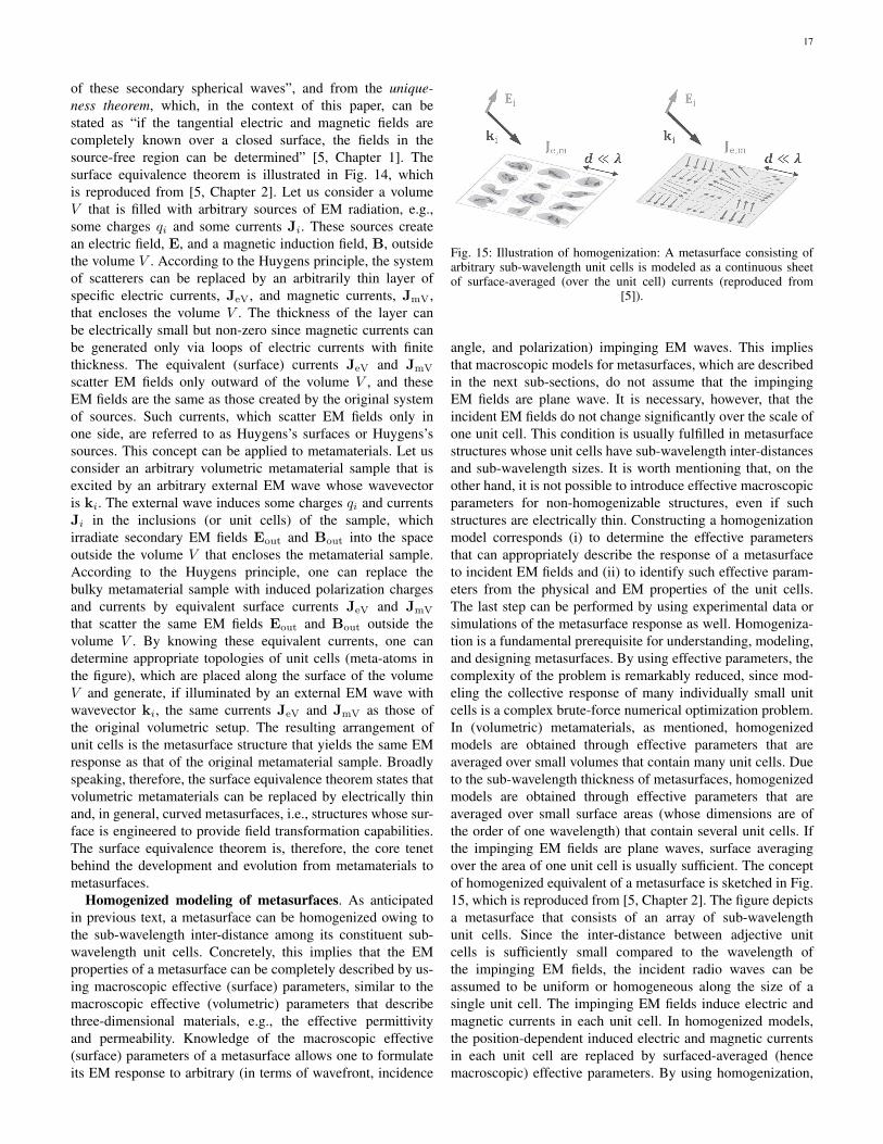
17
of these secondary spherical waves”, and from the unique-ness theorem, which, in the context of this paper, can bestated as “if the tangential electric and magnetic fields arecompletely known over a closed surface, the fields in thesource-free region can be determined” [5, Chapter 1]. Thesurface equivalence theorem is illustrated in Fig. 14, whichis reproduced from [5, Chapter 2]. Let us consider a volumeV that is filled with arbitrary sources of EM radiation, e.g.,some charges qi and some currents Ji. These sources createan electric field, E, and a magnetic induction field, B, outsidethe volume V . According to the Huygens principle, the systemof scatterers can be replaced by an arbitrarily thin layer ofspecific electric currents, JeV, and magnetic currents, JmV,that encloses the volume V . The thickness of the layer canbe electrically small but non-zero since magnetic currents canbe generated only via loops of electric currents with finitethickness. The equivalent (surface) currents JeV and JmV
scatter EM fields only outward of the volume V , and theseEM fields are the same as those created by the original systemof sources. Such currents, which scatter EM fields only inone side, are referred to as Huygens’s surfaces or Huygens’ssources. This concept can be applied to metamaterials. Let usconsider an arbitrary volumetric metamaterial sample that isexcited by an arbitrary external EM wave whose wavevectoris ki. The external wave induces some charges qi and currentsJi in the inclusions (or unit cells) of the sample, whichirradiate secondary EM fields Eout and Bout into the spaceoutside the volume V that encloses the metamaterial sample.According to the Huygens principle, one can replace thebulky metamaterial sample with induced polarization chargesand currents by equivalent surface currents JeV and JmV
that scatter the same EM fields Eout and Bout outside thevolume V . By knowing these equivalent currents, one candetermine appropriate topologies of unit cells (meta-atoms inthe figure), which are placed along the surface of the volumeV and generate, if illuminated by an external EM wave withwavevector ki, the same currents JeV and JmV as those ofthe original volumetric setup. The resulting arrangement ofunit cells is the metasurface structure that yields the same EMresponse as that of the original metamaterial sample. Broadlyspeaking, therefore, the surface equivalence theorem states thatvolumetric metamaterials can be replaced by electrically thinand, in general, curved metasurfaces, i.e., structures whose sur-face is engineered to provide field transformation capabilities.The surface equivalence theorem is, therefore, the core tenetbehind the development and evolution from metamaterials tometasurfaces.
Homogenized modeling of metasurfaces. As anticipatedin previous text, a metasurface can be homogenized owing tothe sub-wavelength inter-distance among its constituent sub-wavelength unit cells. Concretely, this implies that the EMproperties of a metasurface can be completely described by us-ing macroscopic effective (surface) parameters, similar to themacroscopic effective (volumetric) parameters that describethree-dimensional materials, e.g., the effective permittivityand permeability. Knowledge of the macroscopic effective(surface) parameters of a metasurface allows one to formulateits EM response to arbitrary (in terms of wavefront, incidence
Fig. 15: Illustration of homogenization: A metasurface consisting ofarbitrary sub-wavelength unit cells is modeled as a continuous sheetof surface-averaged (over the unit cell) currents (reproduced from
[5]).
angle, and polarization) impinging EM waves. This impliesthat macroscopic models for metasurfaces, which are describedin the next sub-sections, do not assume that the impingingEM fields are plane wave. It is necessary, however, that theincident EM fields do not change significantly over the scale ofone unit cell. This condition is usually fulfilled in metasurfacestructures whose unit cells have sub-wavelength inter-distancesand sub-wavelength sizes. It is worth mentioning that, on theother hand, it is not possible to introduce effective macroscopicparameters for non-homogenizable structures, even if suchstructures are electrically thin. Constructing a homogenizationmodel corresponds (i) to determine the effective parametersthat can appropriately describe the response of a metasurfaceto incident EM fields and (ii) to identify such effective param-eters from the physical and EM properties of the unit cells.The last step can be performed by using experimental data orsimulations of the metasurface response as well. Homogeniza-tion is a fundamental prerequisite for understanding, modeling,and designing metasurfaces. By using effective parameters, thecomplexity of the problem is remarkably reduced, since mod-eling the collective response of many individually small unitcells is a complex brute-force numerical optimization problem.In (volumetric) metamaterials, as mentioned, homogenizedmodels are obtained through effective parameters that areaveraged over small volumes that contain many unit cells. Dueto the sub-wavelength thickness of metasurfaces, homogenizedmodels are obtained through effective parameters that areaveraged over small surface areas (whose dimensions are ofthe order of one wavelength) that contain several unit cells. Ifthe impinging EM fields are plane waves, surface averagingover the area of one unit cell is usually sufficient. The conceptof homogenized equivalent of a metasurface is sketched in Fig.15, which is reproduced from [5, Chapter 2]. The figure depictsa metasurface that consists of an array of sub-wavelengthunit cells. Since the inter-distance between adjective unitcells is sufficiently small compared to the wavelength ofthe impinging EM fields, the incident radio waves can beassumed to be uniform or homogeneous along the size of asingle unit cell. The impinging EM fields induce electric andmagnetic currents in each unit cell. In homogenized models,the position-dependent induced electric and magnetic currentsin each unit cell are replaced by surfaced-averaged (hencemacroscopic) effective parameters. By using homogenization,

18
therefore, a metasurface is modeled as a planar thin sheet ofelectric and magnetic surface-averaged current densities or, asdescribed in further text, polarization surface densities. Thisimplies that the modeling and analysis of the scattering from ametasurface that is made of finite-size (or discrete) unit cells isturned into the modeling and analysis of the scattering from anequivalent continuous sheet of electric and magnetic currents.
C. On Modeling Metasurfaces: A Macroscopic HomogenizedApproach
Starting from the introductory material on SEM, this sub-section is focused on reporting tractable analytical modelsfor metasurfaces. Special emphasis is, in particular, put onthe theory that leads from a microscopic to a macroscopicrepresentation of metasurfaces through surface-averaged ho-mogenized effective parameters.
From a microscopic to a macroscopic representation.We consider an RIS made of a metasurface according tothe definition given in Section II, i.e., the smart surface iselectrically thin, electrically large, homogenizable, and has asub-wavelength structure. Under these assumptions, we beginour development by introducing a microscopic description ofa metasurface that is based on and accounts for the spatialcoupling between adjacent unit cells, which is due to their sub-wavelength inter-distance. The obtained physics-based modelmay not, however, be sufficiently flexible for designing andanalyzing complex metasurfaces. Subsequently, for this rea-son, we introduce a macroscopic description of a metasurface,which is based on continuous tensor functions, that yields amore suitable representation of a metasurface, especially forapplication to wireless networks. The macroscopic approach,however, still allows us to obtain a direct connection with thematerial parameters, i.e., the surface susceptibility of the smartsurface. Based on the introduced macroscopic description ofa metasurface, finally, we discuss its synthesis and analysis.
Reconciling communication and electromagnetism. It isworth mentioning that the approach reported in this sub-section is widely employed in the fields of electromagnetismand metamaterials, and our treatise is mainly based on thetheories available in [29], [30], [31], [32], [33]. These methodsare, however, not necessarily known to wireless researchers.The main objective of this sub-section is to fill this gap ofknowledge in a simple but rigorous manner, and with the aidof some examples and case studies.
1) EM-Based Model of a Metasurface: Our departing pointis the EM-based model of a metasurface reported in [29], [30].
A metasurface as a surface distribution of electricallysmall resonant scatterers. In the most general sense, a meta-surface (also called a metafilm in [29], [30]) is viewed as a sur-face distribution of electrically small resonant scatterers, and itis characterized by electric and magnetic surface polarizationdensities. In simple terms, the electrically small scatterersare the unit cells in Fig. 4. In volumetric, three-dimensionalmaterials, the electric polarization density is a vector fieldthat expresses the density of permanent or induced electricdipole moments in a dielectric material. When a dielectric isplaced in an external electric field, its molecules gain electric
Fig. 16: Example of induced electric dipole moment and electricpolarization density (P) in volumetric materials.
dipole moment and the dielectric is said to be polarized.The electric dipole moment induced per unit volume of thedielectric material is referred to as the electric polarization ofthe dielectric. The electric polarization density describes howa material responds to an applied electric field and how thematerial changes the electric field. More precisely, an externalelectric field that is applied to a dielectric material causes adisplacement of bound charged elements, which are elementsbound to molecules and, hence, are not free to move aroundthe material. Positive charged elements are displaced in thedirection of the electric field and negative charged elements aredisplaced in the opposite direction of the field. The moleculesmay remain neutral in charge, but an electric dipole momentis formed. The electric polarization density corresponds tothe induced dipole moment per unit volume of the material.For ease of understanding, this concept is sketched in Fig.16. Similarly, the magnetic polarization density describes howa material responds to an applied magnetic field. To modelmetasurfaces as sheets of electrically negligible thickness, theconcept of electric and magnetic surface polarization densitiesis used. The electric (magnetic) surface polarization densityis the electric (magnetic) dipole moment per unit area ofthe surface, while the usual volumetric electric (magnetic)polarization density is the electric (magnetic) dipole momentper unit volume.
A metasurface as an array of polarizable unit cells. Ametasurface can be broadly defined as an array of polarizableunit cells that induce discontinuities of the electric and mag-netic fields at the two sides of the surface, i.e., at z = 0+ andz = 0− in Fig. 4. The objective of a macroscopic descriptionof a metasurface consists of formulating and expressing thediscontinuities of the electric and magnetic fields as a functionof surface-averaged electric and magnetic surface polarizationdensities. Since a metasurface is homogenizable, i.e., thedistance between adjacent unit cells is much smaller than thewavelength of the radio waves, the approach consists of re-placing the discrete distribution of unit cells with a continuousdistribution, which, in turn, results in a continuous function ofelectric and magnetic surface polarization densities. It is worth

19
Fig. 17: Equivalent analytical representation of a metasurface: A zero-thickness material sheet whose EM properties are modeled throughsurface susceptibility functions that introduce EM discontinuities (or“jumps”) quantified by the generalized sheet transition conditions.
nothing that the unit cells may be of arbitrary shape and arenot infinitely thin. Their thickness is only required to be smallin comparison with the wavelength of the radio waves.
Towards a macroscopic description. A macroscopic de-scription of a metasurface consists of replacing the actualspatial distribution of the unit cells on the smart surface withanalytical relations between the electric and magnetic fields atthe two sides of the metasurface (at z = 0+ and z = 0− in Fig.4). Conceptually, this equivalence is illustrated in Fig. 17. Thesize, the shape, and the physical characteristics of the unit cellsare directly incorporated into these analytical relations throughthe homogenized (continuous) electric and magnetic surfacepolarization densities. The analytical relations that express theelectric and magnetic fields at the two sides of a metasurfaceas functions of the homogenized (continuous) electric andmagnetic surface polarization densities are referred to asgeneralized sheet transition conditions (GSTCs). It is worthanticipating that the EM fields and the effective parametersthat appear in a macroscopic formulation of the GSTCs aresurface-averaged quantities, i.e., they are averaged over smallareas of the order of a wavelength.
Generalized sheet transition conditions. As far as theGSTCs are concerned, three remarks are worth mentioning.• The tangential components of the EM fields are suf-
ficient. The electric and magnetic fields that appear inthe GSTCs involve only their tangential (or transverse)components across the surface. In other words, the carte-sian or longitudinal component of the EM fields alongthe z-axis in Fig. 4 does not explicitly appear. This is be-cause they can be uniquely determined by the transversecomponents by virtue of the uniqueness theorem [31].
• The EM fields have variations on scales larger than thewavelength. The electric and magnetic fields that appearin the GSTCs do not exhibit variations on a length scalethat is comparable with the dimension of the unit cellsand with their inter-distance. They only exhibit variationson a length scale that is larger than the wavelengthof the radio waves. In the present paper, however, thecorresponding model is still referred to as microscopicbecause it requires an appropriate definition of the spatialcoupling between adjacent unit cells [29]. We use theterm macroscopic modeling to identify similar analyticalrelations in which this coupling is implicitly taken intoaccount by using surface-averaged susceptibility tensorfunctions [31]. This concept is better elaborated in furthertext.
TABLE I: Recurrent notation (k = 2π/λ = ω√µε).
Symbol Definition()∗ Complex conjugate
Re {·} Real part()T Matrix transpose
()H Hermitian conjugate
()† Pseudo inverse· Scalar product× Vector product() Unit vectorλ Wavelengthω Angular frequencyε Permittivity in vacuumµ Permeability in vacuumη =
√µ/ε Impedance in vacuum
k WavenumberP(x, y) Electric surface polarization densityM(x, y) Magnetic surface polarization densityP‖ (x, y) Longitudinal component of P(x, y)M‖ (x, y) Longitudinal component of M(x, y)E(x, y, z) Electric fieldH(x, y, z) Magnetic fieldD(x, y, z) Electric displacement fieldEx,y(x, y) Tangential components of the electric fieldHx,y(x, y) Tangential components of the magnetic fieldi, r, t Incident, reflected, transmitted fieldθi, θr, θt Angle of incidence, reflection, transmissionχab (x, y) Surface susceptibility dyadicsR(x, y) Surface reflection coefficient
• Generalization of conventional interface conditions. TheGSTCs, which best characterize a metasurface as an EMdiscontinuity, constitute a generalization of conventionalinterface conditions for the EM fields at the interface oftwo media. For example, it is known that the tangentialcomponents of the electric field are continuous at theinterface of two media. This is not true if the interface isconstituted by a zero-thickness metasurface that acts asan EM discontinuity. The relations between the tangentialcomponents of the electric and magnetic fields are, infact, specified by the GSTCs. In general, the tangentialcomponents of the electric and magnetic fields are dif-ferent at the two sides of a metasurface, i.e., they arediscontinuous. It is usual jargon to say that the GSTCsformulate the “jumps” (i.e., discontinuities) of the electricand magnetic fields at the two sides of a metasurface.
2) Microscopic Description of a Metasurface: From unitcells to mathematics. After introducing the general defi-nition of GSTCs and the general meaning of macroscopichomogenized description of a metasurface, we are ready toformulate these two concepts in analytical terms. To this end,we depart from the physical structure of a metasurface and itsmicroscopic representation. The corresponding macroscopichomogenized description is derived in the next sub-section.
Metasurface structure. We consider a two-dimensional

20
metasurface that lies on the xy-plane at z = 0. The meta-surface is centered at the origin and has a finite size equalto 2Lx and 2Ly along the x-axis and y-axis, i.e., −Lx ≤x ≤ Lx and −Ly ≤ y ≤ Ly , respectively. Without lossof generality, we assume that the incidence-reflection side ofthe metasurface is z = 0+ and the transmission side of themetasurface is z = 0−. Also, we assume that the mediumsurrounding the metasurface is vacuum. The symbols anddefinition used throughout the present paper are reported inTable I. Our analytical formulation is mostly based on [31],[32], [33]. For simplicity, we consider the sufficient generalcase of metasurfaces whose longitudinal components of theelectric (P) and magnetic (M) surfaces polarization densitiesare equal to zero, i.e., Pz = 0 and Mz = 0, respectively.We show in further text that this assumption allows one todesign metasurfaces that realize EM-based functions that aresufficiently general for wireless applications, e.g., reflectionand refraction towards arbitrary directions. The advantage ofthis assumption is that closed-form analytical expressions forthe EM fields are obtained.
Analytical formulation of GSTCs. Let us consider an EMfield that illuminates a metasurface. Under the assumptionPz = 0 and Mz = 0, the GSTCs, i.e., the “jumps” of theelectric and magnetic fields at the two sides of a metasurface,can be formulated as follows:
z ×∆H (x, y) = jωP‖ (x, y)
∆E (x, y)× z = jωµM‖ (x, y)(1)
where P‖ (x, y) and M‖ (x, y) are the longitudinal compo-nents of the surface-averaged electric and magnetic surface po-larization densities, respectively, and ∆E (x, y) and ∆H (x, y)are the differences between the surface-averaged electric andmagnetic fields at the two sides of the metasurface, whosecartesian components can be written, respectively, as follows:
∆Ψu (x, y) = u · ∆Ψ (x, y)|z=0+
z=0−
= Ψtu (x, y)−
(Ψiu (x, y) + Ψr
u (x, y)) (2)
where Ψ = {E,H}, u = {x, y, z}, and the superscriptsi, r and t denote the incident, reflected, and transmittedcomponents of the fields, respectively.
Computing P and M. The GSTCs depend on the lon-gitudinal components of the electric and magnetic surfacepolarization densities. In order to formulate and compute them,we need to investigate the working operation of a metasurfaceat the microscopic level and we need to introduce the conceptof acting (or local) fields.
Acting (or local) field: Excitation field at the location ofan individual unit cell. At the microscopic level, a metasur-face is viewed as an array of electrically small polarizable unitcells. When an EM field illuminates a metasurface, the unitcells get polarized and, since they are small (sub-wavelength)in size, the induced polarizations of each individual unit cellcan be modeled through induced electric and magnetic dipolemoments (see Fig. 16). Since the unit cells are arranged ina dense array, i.e., the inter-distance between adjacent unitcells is sub-wavelength, knowing the polarization induced on asingle unit cell is not sufficient to determine the response of the
entire metasurface. This is because the EM field that excitesa unit cell that occupies a specific location, which is referredto as the acting or local EM field, is given by the summationof the incident EM field and the, so-called, interaction EMfield, which is the field created by the induced electric andmagnetic dipoles of all the unit cells of the metasurface withthe exception of the unit cell under analysis.
Acting field: Modeling the mutual coupling among unitcells. By definition, therefore, the acting electric and magneticfields account for the contribution of all the unit cells of ametasurface with the exception of the given unit cell underconsideration. This implies that they account for the mutual(spatial) coupling among the unit cells of a metasurface andthat they yield a microscopic description of a metasurface,since the acting fields are referred to individual unit cells.If the acting fields are known, the electric (P) and magnetic(M) surfaces polarization densities in (1) can be formulatedas follows [29]:
P (x, y) = εN〈αee (x, y)〉Eact (x, y)
+√µεN〈αem (x, y)〉Hact (x, y)
(3)
M (x, y) =√ε/µN〈αme (x, y)〉Eact (x, y)
+N〈αmm (x, y)〉Hact (x, y)(4)
where N is the number of unit cells per unit area, and〈αab (x, y)〉, for a = {e,m} and b = {e,m}, are the aver-age (electric-electric, electric-magnetic, magnetic-electric, andmagnetic-magnetic) polarizability dyadics of the unit cell inwhich the electric and magnetic surface polarization densitiesare computed. In particular, the average 〈·〉 is calculated overthe unit cells in the vicinity of the unit cell being consideredand where the electric and magnetic surfaces polarizationdensities are evaluated. The polarizability dyadics depend onthe physics and EM properties of the unit cells. As far as thepresent paper is concerned, it is sufficient to know that theycan be obtained from analysis, simulations, or measurements.
Relating local (microscopic) fields to average (macro-scopic) fields. Based on (3) and (4), the electric and magneticsurface polarization densities can be formulated in terms of theacting electric (Eact (x, y)) and magnetic (Hact (x, y)) fieldsat the position of a given unit cell. By definition, the actingfields can be formulated as follows [29]:
Eact (x, y) = Eav (x, y)−Eunit cellscattering (x, y)
Hact (x, y) = Hav (x, y)−Hunit cellscattering (x, y)
(5)
where Eav (x, y) and Hav (x, y) are the average electric andmagnetic fields, respectively, at the two sides of the metasur-face, which are defined as follows:
Eav,u (x, y) =Etu (x, y) +
(Eiu (x, y) + Eru (x, y)
)2
Hav,u (x, y) =Htu (x, y) +
(Hiu (x, y) +Hr
u (x, y))
2
(6)
where u = {x, y, z}, and Eunit cellscattering (x, y) and
Hunit cellscattering (x, y) are the electric and magnetic fields scattered
by the single unit cell under consideration, respectively.Contribution of a single unit cell. In practice, the contri-

21
bution of a single unit cell can be calculated by expressing theunit cell as a combination of electric and magnetic dipoles thatare contained within a small disk of a given radius. The electricand magnetic fields scattered by the resulting small disk are,by definition, Eunit cell
scattering (x, y) and Hunit cellscattering (x, y).
Surface-averaged fields. It is worth emphasizing that(5) relates local, hence microscopic, fields to average,hence macroscopic, fields. More specifically, Eav (x, y) andHav (x, y) in (6) are surface-averaged fields, where the averageis computed over a small surface area of the order of thewavelength (including one or more unit cells depending onthe setup). In other words, the rapid variations of the EMfields over distances of the order of the typical separationbetween adjacent unit cells along the surface are eliminated(i.e., averaged out) in macroscopic EM fields. This is not thecase for microscopic EM fields.
The need for a macroscopic representation. By inserting(3) and (4) into (1), one can obtain the analytical relationsbetween the transverse components of the electric and mag-netic fields at the two sides of a metasurface. The issue withthis approach is that the acting electric and magnetic fieldsneed to be estimated, which depend on a specific unit cell,i.e., Eunit cell
scattering (x, y) and Hunit cellscattering (x, y), and may not be
easy to deal with. This issue is overcome next, by introducingan explicit macroscopic description of a metasurface, whichdepends only on the average (macroscopic) fields.
3) Macroscopic Description of a Metasurface: Explicitmacroscopic formulation. In [29], the authors succeed incalculating a closed-form expression for Eunit cell
scattering (x, y) andHunit cell
scattering (x, y). Based on their analytical formulation, theelectric and magnetic surface polarization densities in (3) and(4) can be formulated in terms of the average electric andmagnetic fields in (6), which, in contrast with the actingfields, yield a macroscopic description of a metasurface thatis viewed as an electromagnetic discontinuity in space. This isbecause the average fields do not exclude the fields generatedby individual unit cells.
Surface-averaged susceptibility functions: The effectiveparameters of metasurfaces. More specifically, a macro-scopic description of a metasurface, which depends only onaverage (macroscopic) electric and magnetic fields, can beobtained by formulating the electric and magnetic surfacepolarization densities in terms of susceptibility tensors ratherthan in terms of polarizabilities. Similar to the average fields,the susceptibility tensors are macroscopic surface-averagedparameters. They can can be viewed as the effective parame-ters of metasurfaces, in analogy with the electric permittivityand magnetic permeability of volumetric metamaterials, andthey depend on the topology and geometry of the unit cells,the inter-distance among the unit cells, the properties of thematerial, and the wavelength. In particular, the followingrelations hold true [31]:
P (x, y) = εχee (x, y) Eav (x, y)
+√µεχem (x, y) Hav (x, y)
(7)
M (x, y) =√ε/µχme (x, y) Eav (x, y)
+ χmm (x, y) Hav (x, y)(8)
where χab (x, y), for a = {e,m} and b = {e,m}, arethe (electric-electric, electric-magnetic, magnetic-electric, andmagnetic-magnetic) surface-averaged (or simply surface) sus-ceptibility dyadics, which are the macroscopic quantities ofinterest for a simple but accurate synthesis and analysis ofmetasurfaces.
GSTCs: A macroscopic algebraic formulation. With theaid of the analytical formulation of the electric and magneticsurface polarization densities as a function of only macro-scopic fields and surface susceptibility dyadics, one can obtainan explicit analytical (algebraic) formulation of the GSTCs.More specifically, by inserting (7) and (8) into (1), the follow-ing explicit relation can be obtained (for ease of notation, thedependency on (x, y) for all fields and susceptibility dyadicsis explicitly omitted but implied):[−Ht
y +Hiy +Hr
y
Htx −Hi
x −Hrx
]=jωε
2
[χxxee χxyee
χyxee χyyee
] [Etx + Eix + ErxEty + Eiy + Ery
]+jω√µε
2
[χxxem χxyem
χyxem χyyem
] [Htx +Hi
x +Hrx
Hty +Hi
y +Hry
] (9)
[Ety − Eiy − Ery−Etx + Eix + Erx
]=jωµ
2
[χxxmm χxymm
χyxmm χyymm
] [Htx +Hi
x +Hrx
Hty +Hi
y +Hry
]+jω√µε
2
[χxxme χxyme
χyxme χyyme
] [Etx + Eix + ErxEty + Eiy + Ery
] (10)
where, for a = {e,m} and b = {e,m}, we have introducedthe notation:
χab (x, y) =
[χxxab (x, y) χxyab (x, y)χyxab (x, y) χyyab (x, y)
](11)
GSTCs: A mathematical tool for analysis and synthesis.The analytical expressions in (9) and (10) provide one withthe necessary equations for designing metasurfaces, which arecapable of applying specified transformations to the impingingradio waves, and for analyzing the performance of wirelessnetworks in the presence of metasurfaces. These two importantissues are discussed in the next two sub-sections. Beforetackling them, we close this sub-section by emphasizing fourimportant properties of the constitutive relations in (9) and(10): (i) the constitutive relations are formulated only in termsof macroscopic surface-averaged EM fields and macroscopicsurface-averaged effective parameters; (ii) the analysis ofthe surface-averaged susceptibility functions allows one tounderstand whether the metasurface is locally lossy, i.e., theirimaginary part is always negative, or whether some local gainsare needed, i.e., their imaginary part takes positive values;(iii) even though the constitutive relations offer a macroscopicdescription of a metasurface, they inherently account for themutual coupling among the unit cells, since they originate froma microscopic description of a metasurface. In particular, themutual coupling between adjacent unit cells is implicitly takeninto account in the surface-averaged susceptibility matrices in(11). This point will be further clarified in the next sub-section;

22
Fig. 18: Homogenization modeling of a metasurface based on surface-averaged impedances (reproduced from [5]).
and (iv) the constitutive relations in (9) and (10) can be appliedto formulate the EM response of a metasurface to arbitrary(in terms of wavefront, incidence angle, and polarization)impinging EM waves. This implies that (9) and (10) do notassume that the impinging EM fields are plane waves. It isnecessary, however, that the incident EM fields do not changesignificantly over the scale of one unit cell. This conditionis usually fulfilled in metasurface structures whose unit cellshave sub-wavelength inter-distances and sub-wavelength sizes.
Main takeaway. In summary, the main takeaway messageis that, from an analytical point of view, a metasurface canbe approximately replaced by its corresponding constitutiverelations in (9) and (10), which are sufficient for the analysisand design of wireless networks (see Fig. 17).
Equivalent representation in terms of surface-averagedimpedances. An alternative homogenization model for a meta-surface can be obtained by establishing an analogy betweenthe propagation of radio waves in vacuum and the propagationof signals in transmission lines [5, Chapter 2]. In this analogy,more precisely, the electric and magnetic fields of a radiowave that propagates in vacuum are matched to the voltagesand currents of a signal that propagates in an equivalenttransmission line, respectively. The impedances that deter-mine the equivalent transmission line constitute a macroscopicsurface-averaged representation of a metasurface, which isequivalent to the representation of a metasurface in termsof surface-averaged susceptibility functions. An example ofrepresentation of a metasurface in terms of transmission lineequivalent is reported in Fig. 18, which is reproduced from[5, Chapter 2]. The T-circuit transmission line in Fig. 18ensures, in particular, that there exist “jumps” (discontinuities)of both the electric and magnetic fields, i.e., the voltagesand currents represented in the figure, in agreement with theGSTCs in (1). By applying Kirchhoff’s circuit laws to theequivalent transmission line representation of the metasurface,and by inserting the resulting equations in (9) and (10), onecan compute analytical relations between the surface-averagedsusceptibility functions and the surface-averaged impedancesof the transmission line equivalent in Fig. 18. An example ofthis computation and an explicit relation between the two rep-resentations for a metasurface can be found in [34, Appendix].The homogenization model formulated in terms of surface-averaged impedances provides one with useful engineeringinsights on the properties of a metasurface structure. Forexample, a metasurface is capacitive and inductive if theimaginary part of the impedances is negative and positive, re-
spectively, and a metasurface is lossy and active if the real partof the impedances is positive and negative, respectively. Asremarked in [34], more in general, a representation of a meta-surface in terms of circuital parameters, i.e., surface-averagedimpedances, may be potentially more useful to engineering-oriented communities, while a representation of a metasurfacein terms of surface-averaged susceptibility functions maybe more widely used in physics-oriented communities. Bothrepresentations are, however, homogenized, macroscopic, andequivalent with each other. An example of application ofthe homogenized modeling of metasurfaces based on surface-averaged impedances is given in the next sub-section.
4) Synthesis of a Metasurface: How to build my ownmetasurface? The synthesis of a metasurface correspondsto the following problem formulation: Given some specifiedradio wave transformations, i.e., the incident, reflected, andtransmitted electric and magnetic fields are known, identifythe corresponding susceptibility matrices in (11) that realizethem, and then map the susceptibility matrices into physicalstructures that are made of specific arrangements of unit cells.Therefore, this is a two-part design problem. We elaboratethe details of both sub-problems in this sub-section, firstin general terms and then with the aid of an example thatelucidates some important details.
Computation of susceptibility functions. Given Eξv(x, y) andHξv (x, y) for v = {x, y} and ξ = {i, r, t}, the surface
susceptibility functions in (11) can be obtained by solving thetwo systems of intertwined equations in (9) and (10).
An undetermined system of equations. The combinedsystem of (9) and (10) is constituted by four equations andsixteen unknowns. Therefore, it is an undetermined systemof equations that admits, in general, an infinite number ofsolutions. In practical terms, this implies that there exist manydifferent combinations of surface susceptibility functions in(11) that realize the same transformations of the incidentelectric and magnetic fields into the reflected and transmittedelectric and magnetic fields. A simple approach for overcom-ing the undetermined nature of the system of equations in(9) and (10) is to reduce to four the number of independentsurface susceptibility functions in (11). For example, some ofthem may be set equal to zero, provided that the resultingmetasurface admits a physical structure that can be realized inpractice.
A simple example. To better understand, let us consider thecase study in which the constraints χem (x, y) = χme (x, y) =0 and χxyee (x, y) = 0, χyxee (x, y) = 0, χxymm (x, y) = 0,χyxmm (x, y) = 0 are imposed to the surface susceptibilityfunctions. From a physical standpoint, this implies that themetasurface structure is monoanisotropic (i.e., its physicalproperties exhibit variations along one direction) and uniaxial(i.e., it has a single direction of symmetry), and, therefore, it isreciprocal. Under these assumptions, the following analyticalexpressions for the remaining surface susceptibility functionscan be obtained from (9) and (10):
χxxee (x, y) = − 2
jωε
Hty (x, y)−Hi
y (x, y)−Hry (x, y)
Etx (x, y) + Eix (x, y) + Erx (x, y)(12)

23
χyyee (x, y) =2
jωε
Htx (x, y)−Hi
x (x, y)−Hrx (x, y)
Ety (x, y) + Eiy (x, y) + Ery (x, y)
χxxmm (x, y) =2
jωµ
Ety (x, y)− Eiy (x, y)− Ery (x, y)
Htx (x, y) +Hi
x (x, y) +Hrx (x, y)
χyymm (x, y) = − 2
jωµ
Etx (x, y)− Eix (x, y)− Erx (x, y)
Hty (x, y) +Hi
y (x, y) +Hry (x, y)
The case of perfect anomalous reflection. Giventhe explicit expressions of the incident, reflected, andtransmitted fields, (12) yields a metasurface that can realizeboth anomalous reflection and anomalous transmission.If, for example, perfect reflection is of interest, i.e.,Etx (x, y) = Ety (x, y) = 0 and Ht
x (x, y) = Hty (x, y) = 0,
then one obtains χxxee (x, y)χyymm (x, y) = −4/k2 and
χyyee (x, y)χxxmm (x, y) = −4/k2, where k = ω
√µε. If a
perfect reflector needs to be realized, therefore, only oneindependent surface susceptibility function is needed. Thiscase study is elaborated in more detail in further text.
Realization of physical lattices of unit cells. Once the ana-lytical expressions of the surface susceptibility functions areobtained, e.g., the formulas in (12), the next step is to mapthese functions into a physical structure of unit cells that canbe realized and manufactured. This latter step is, in particular,the most difficult one to implement.
Periodicity of a metasurface. Before introducing the cor-responding procedure, it is worth mentioning that the surfacesusceptibility functions that are obtained from (9) and (10)may or may not be periodic functions in (x, y). If they areperiodic functions, the periodicity of a metasurface coincideswith the period of the surface susceptibility functions, whichis usually expressed in terms of number of wavelengths. Ifthe incident, reflected, and transmitted radio waves are planewaves, for example, the surface susceptibility functions areperiodic functions in (x, y). If more advanced functionalitiesare needed, e.g., focusing, aperiodical metasurfaces are usuallyneeded, and the corresponding surface susceptibility functionsare not periodic functions (x, y). As far as periodic metasur-faces are concerned, it is worth mentioning that the period ofthe surface susceptibility functions is usually greater than thewavelength. The periodic feature of the surface susceptibilityfunctions is clarified in further text with an example. In therest of the present paper, for simplicity, we will assume thatthe surface susceptibility functions are periodic functions in(x, y).
Step-by-step procedure. The procedure that is usuallyadopted for mapping the surface susceptibility functions intometasurface structures can be summarized, in general terms,as follows [35].
1) Identifying the super-cell. The continuous surface sus-ceptibility functions are discretized (or sampled) in unitcells whose size and inter-distance are sub-wavelength.Thanks to the periodic nature of the surface suscepti-bility functions, this operation is executed for a singleperiod. The discretization is performed by ensuring thata sufficient number of unit cells per period is obtainedin agreement with the Nyquist theorem. This step yieldsthe discretized version of (11), i.e., χab (xp, yq), for
Fig. 19: Dog-bone-shaped unit cell and super-cell structure (exampleand illustration are reproduced from [35]).
p = 1, 2, . . . , Np and q = 1, 2, . . . , Nq , where Np andNq are the numbers of unit cells, in one period, along thex-axis and y-axis, respectively. The obtained Np × Nqunit cells correspond to the super-cell depicted in Fig.4. We anticipate that the entire metasurface is obtainedas the periodic repetition of the super-cell structure.
2) Optimizing the super-cell. Once the super-cell structuremade of Np ×Nq unit cells is identified, the geometryof each unit cell of the super-cell needs to be optimized.In general, in fact, the unit cells of the super-cell mayhave a different geometry (size and shape). This opti-mization is executed by using a full-wave simulator thatallows one to solve Maxwell’s equations numerically. Ingeneral, this implies that the Np ×Nq unit cells of thesuper-cell are jointly optimized in this step. To performthis optimization by using a full-wave simulator, firsta generic structure and geometry for the unit cell areselected. This choice takes into account the fact thatthe structure and geometry of the unit cells need to beappropriate in order to synthesize the entire phase andamplitude range of the discretized surface susceptibilityfunctions. In [35], for example, the authors employ adog-bone-shaped geometry for the generic unit cell,which has four optimization parameters (G, L, S, W ), asdepicted in Fig. 19. In [35], the super-cell is constitutedby Np×Nq unit cells that are all dog-bone-shaped. Eachunit cell of the super-cell is, however, characterized bya different quadruplet of parameters (G, L, S, W ).
3) Metasurfaces: A periodic repetition of super-cells.Finally, as anticipated, the metasurface is obtained as theperiodic repetition of the optimized super-cell structure.This is allowed thanks to the periodicity of the surfacesusceptibility functions, provided that the super-cell isappropriately defined by taking the exact period intoaccount.
Rationale behind the super-cell structure. As far as theoptimization of the structure and geometry of the super-cell(the above-mentioned second step) is concerned, three remarksare dutiful.• Periodic boundary conditions. The optimization of the
geometry and structure of the entire super-cell is executedby enforcing periodic boundary conditions in a full-wave simulator. This is a plausible choice thanks tothe periodicity of the surface susceptibility functions,whose period is, by design, entirely covered by the

24
super-cell. More specifically, the super-cell constitutesthe so-called representative surface (or, in general, vol-ume) element of the periodic structure that determinesa metasurface. Therefore, it is sufficient, under periodicboundary conditions, to account for the behavior of theentire metasurface. It is important to mention, however,that this approximation is appropriate if the size of themetasurface is large as compared with the wavelength ofthe radio waves and if the area of the surface containsmany periods. With this approximation, in particular,edge effects are ignored.
• Mutual (spatial) coupling. The joint optimization of theNp × Nq unit cells of the super-cell and the applica-tion of the periodic boundary conditions when solvingMaxwell’s equations with a full-wave simulator allowone to effectively account for the mutual coupling amongthe unit cells. The mutual coupling is, in fact, needed inorder to synthesize, in practice, the desired discretizedsurface susceptibility functions. The resulting structureof the metasurface is locally aperiodic, since it is madeof different adjacent unit cells, but the the super-cellstructure enforces the required periodicity across theentire metasurface.
• Efficient optimization. The joint optimization of theunit cells of the super-cell may not be computationallyaffordable. For example, a super-cell with only ten unitcells, each of which has four parameters to be optimized,necessitates the joint optimization of forty variables. Tocircumvent this issue and to efficiently design metasur-faces of practical use, iterative and often sub-optimalmethods may be employed. For example, one may firstoptimize the geometry and size of each unit cell of thesuper-cell individually, by enforcing periodic boundaryconditions to each unit cell. Since a single unit cell doesnot cover an entire period of the surface susceptibilityfunctions, the resulting design is an approximation. Theobtained sub-optimal design may, however, be subse-quently used as the starting point for jointly optimizingall the unit cells of the super-cell. For example, one mayiteratively optimize one unit cell by keeping the othersfixed, and then iterate the procedure until convergence(under some error tolerance).
The mutual coupling among the unit cells is taken intoaccount by design. The actual realization of a metasurfaceinto a physical lattice of unit cells may not necessarilybe the main objective of researchers working in wirelesscommunications. It is, however, constructive to be awareof and to understand the general procedure employedby researchers working on the actual implementation ofmetasurfaces, in order to appreciate the fact that the mutualcoupling among local neighbors of unit cells is taken intoaccount by design through the periodic repetition of super-cells and the periodic nature of the surface susceptibilityfunctions.
Constructive Example – Perfect anomalous reflection. Inorder to elucidate the procedures for the synthesis and
analysis of a metasurface, we consider a single example thatallows us to highlight some aspects that play an importantrole for the analysis and optimization of RIS-empoweredwireless networks.
Setup and assumptions. The chosen example correspondsto the design of a metasurface that realizes perfect anomalousreflection (zero transmission). For ease of description, in addi-tion, the incident and reflected electric and magnetic fields areassumed to be transverse electric plane waves with an arbitraryangle of incidence and an arbitrary angle of reflection.
Transverse electric plane waves. Under the assumptionof transverse electric plane waves, the tangential electric andmagnetic fields can be formulated as follows [30]:
Eix (x, y) = Erx (x, y) = 0
Eiy (x, y) =√
2ηP0 exp (−jk sin (θi)x)
Ery (x, y) =√
2ηP0Ar exp (−jk sin (θr)x)
Hix (x, y) =
(√2P0/η
)cos (θi) exp (−jk sin (θi)x)
Hrx (x, y) = −
(√2P0/η
)Ar cos (θr) exp (−jk sin (θr)x)
Hiy (x, y) = Hr
y (x, y) = 0(13)
where: (i) η =√µ/ε is the intrinsic impedance in vacuum;
(ii) P0 is the average power density (i.e., the average powerper unit area) of the incident EM field; (iii) θi and θr are theangles of incidence and reflection, respectively, with respectto the z-axis; and (iv) Ar is the amplitude of the reflectedradio wave, which is a scaling factor independent of (x, y).For simplicity, Ar is assumed to be a real positive number. Theamplitude Ar can be chosen according to different criteria. Inthe present paper, we focus our attention on setups for Arthat account for the power flows (obtained from the Poyntingvector) of the incident and reflected EM fields. This choiceallows us to analyze the power efficiency of a metasurface,i.e., the amount of power that is reflected towards the desireddirection given the amount of power that is incident froma given direction, and the design guidelines and constraintsfor engineering metasurfaces with high power efficiency. Thedetails about the conditions for balancing the incident andreflected power flows are discussed in the next paragraphs. It isworth nothing that, given the assumption of transverse electricplane waves, the surface EM fields are independent of y, i.e.,Eiy (x, y) = Eiy (x), Ery (x, y) = Ery (x), Hi
x (x, y) = Hix (x),
and Hrx (x, y) = Hr
x (x).Benchmark EM fields transformation. The analytical for-
mulation of the EM fields in (13) is referred to as benchmarkor desired fields transformation, since it provides one with theideal function that a perfect anomalous reflector is intendedto realize: The metasurface transforms a single incident planewave into a single reflected plane wave, without any spuriousreflections or transmissions towards other (undesired) direc-tions. The EM fields in (13) constitute a theoretical tool thatis used for the synthesis of a perfect anomalous reflector. Infurther text, we discuss different possibilities for representingthe resulting metasurface structure, which are convenient touse in wireless communications and electromagnetics.

25
Surface susceptibility function. Based on (12), the meta-surface structure that realizes the desired EM fields transfor-mation can be obtained by an appropriate design of the surfacesusceptibility functions. Under the considered assumptions, inparticular, a single surface susceptibility function needs to bestudied, e.g., χyyee (x, y), since the other surface susceptibilityfunctions can be obtained from it. In particular, the followingholds true:
χyyee (x, y) = − 2
jωε
Hix (x, y) +Hr
x (x, y)
Eiy (x, y) + Ery (x, y)(14)
where it is taken into account that zero transmission impliesEtx (x, y) = Ety (x, y) = 0 and Ht
x (x, y) = Hty (x, y) = 0.
Explicit analytical formulation and period of a meta-surface structure. By inserting (13) in (14), the surfacesusceptibility function can be formulated as follows:
χyyee (x) =2j
k
cos (θi)−Ar cos (θr) Φ (x)
1 +ArΦ (x)(15)
where Φ (x) = exp (−jk (sin (θr)− sin (θi))x) is a short-hand notation. By direct inspection of (15), we evincethat χyyee (x) is a periodic function in x, i.e., χyyee (x) =χyyee (x+ Π), where Π is the period. In particular, the periodis determined by the function Φ (x) and it is equal to:
Π =2π
k (sin (θr)− sin (θi))(16)
It is worth mentioning that (15) provides one with a generalanalytical representation of a metasurface structure that oper-ates as a perfect anomalous reflector. The specific properties ofthe resulting metasurface, including its power efficiency andimplementation complexity, highly depend on the particularchoice of the parameter Ar. The impact of Ar is elaboratedin the next paragraphs.
Net power flow of the metasurface structure. One of themain features of nearly-passive metasurfaces consists of beingpassive during the normal operation phase. This implies thatthe power flow entering the metasurface structure (incomingpower flow) needs to be less than or equal to the powerflow leaving the metasurface structure (outgoing power flow).The two power flows coincide if the metasurface structurehas unitary power efficiency. Given the (desired) analyticalformulation of the EM fields in (13), the balance between theincoming and outgoing power flows can be ensured by appro-priately optimizing the parameter Ar. Since the metasurfacestructure is periodic, the net power flow can be formulatedfor a single period. More precisely, the net power flow, i.e.the sum of the incoming and outgoing power flows, per unitperiod of the metasurface structure can be obtained from thePoynting vector, as follows:
Pnet (x) = − (1/2) Re{E‖ (x)H∗‖ (x)
}Pnet =
1
Π
∫ Π
0
Pnet (x) dx(17)
where E‖ (x) = E‖ (x, y) = Eiy (x, y) + Ery (x, y) andH‖ (x) = H‖ (x, y) = Hi
x (x, y)+Hrx (x, y) are the tangential
components of the electric and magnetic field, respectively. It
is worth mentioning that it is sufficient to consider a singleperiod because the size of a metasurface is usually set equal toan integer number of periods and the net power flow is usuallynormalized to the total size of the metasurface structure.
By inserting (13) in (17), and computing the resultingintegral, we obtain the following expression:
Pnet (x) = P0A2r cos (θr)− P0 cos (θi)
+ P0Ar (cos (θr)− cos (θi)) cos (φ (x))
Pnet = P0
(A2r cos (θr)− cos (θi)
) (18)
where φ (x) = k (sin (θr)− sin (θi))x is a shorthand notation.Locally and globally passive metasurfaces. The net power
flow of a metasurface structure can be defined in a localand global sense. From a local standpoint, one is interestedin analyzing the surface power flow Pnet (x). From a globalstandpoint, on the other hand, one is interested in analyzingthe integral power flow Pnet. More specifically, the local andglobal power flows in (17) can be negative and positive. Ifthey are negative, it implies that the incident power flow isgreater than the reflected power flow. If they are positive, onthe other hand, the opposite holds true. The physical meaningof negative and positive power flows can be understood byintroducing the definition of locally and globally passivemetasurfaces. A metasurface is defined to be locally passive ifPnet (x) ≤ 0 for every x. Likewise, a metasurface is definedto be globally passive if Pnet ≤ 0. It is worth mentioningthat a locally non-passive metasurface, i.e., Pnet (x) ≥ 0for some x, can be globally passive, i.e., Pnet ≤ 0. Thisoccurs if the metasurface is characterized by regions wherethere are power absorptions and regions where there are powergains that compensate each other along the entire metasurfacestructure. This concept is elaborated in further text, since itis instrumental for realizing metasurfaces with a high powerefficiency.
Globally passive metasurfaces with unitary power ef-ficiency. By definition, globally passive metasurfaces with aunitary power efficiency, i.e., the total reflected power coin-cides with the total incident power, are obtained by imposingthe constraint Pnet = 0. From (18), this can be ensured if:
Ar =
√cos (θi)
cos (θr)(19)
In further text, the physical meaning that originates byimposing that a perfect anomalous reflector is globally passiveby design is discussed. Furthermore, the design guidelines forengineering globally passive metasurface structures that realizeperfect anomalous reflectors with unitary power efficiency areelaborated. It is worth nothing that, by setting Ar as in (19),Pnet (x) in (18) is not identically equal to zero for every x, butit is an oscillating function in x that takes positive and negativevalues. This implies that a perfect anomalous reflector may, ingeneral, exhibit absorptions and gains along the surface. It isinteresting to note, however, that a perfect specular reflector,i.e., θr = θi, can be made locally and globally passive bysetting Ar = 1. In this case, in particular, the incident andreflected power flows coincide and the metasurface structurehas a unitary power efficiency.

26
Surface-averaged reflection coefficient. The EM fields in(13) are necessary and sufficient (benchmark) equations forthe synthesis of a metasurface structure with full-reflectioncapability, which is able of bending a radio wave froma generic direction θi towards a generic direction θr. Thecorresponding surface-averaged susceptibility function is givenin (15). In particular, (15) is a convenient tool for the synthesisof a metasurface. Often, however, researchers are more usedto characterize the properties of structures that behave asreflectors by using the concept of reflection coefficient. Itis important to note that the definition of (surface-averaged)reflection coefficient is slightly different and serves for adifferent purpose in the context of wireless communicationsand in the context of metasurface design. More precisely, thefollowing two definitions hold true.
• Wireless design: Reflection coefficient based on sur-face EM fields. Let us consider that, departing from(15), one has designed and realized the correspondingmetasurface structure by using the synthesis proceduredescribed in previous sections. Wireless researchers areinterested in introducing equivalent representations ofmetasurface structures that yield an explicit and directrelation between the incident and reflected radio waves.In this context, the reflection coefficient is defined as theratio between the reflected electric field and the incidentelectric field. From an engineering standpoint, it canbe viewed as a “global” response of the metasurfacestructure to some incident EM fields. As detailed infurther text, this definition of reflection coefficient isuseful for evaluating the performance of RIS-empoweredwireless networks, since a direct link between incidentand reflected EM fields is established. In the presentpaper, the reflection coefficient defined based on surfaceEM fields is denoted by REM (x, y) = REM (x).
• Metasurface design: Reflection coefficient based onsurface impedances. Let us consider that, departing from(15) (or its corresponding surface-averaged impedance,which is the reciprocal of (15) in the considered example),one has to design and manufacture the correspondingmetasurface structure that realizes the desired anoma-lous reflection. Metasurface scientists are interested inobtaining initial insights from (15), in order to identifyappropriate physical structures that realize the desiredfunctionality. Broadly speaking, the reflection coefficientbased on surface EM fields that is usually employed inwireless communications provides one with informationon “what” needs to be realized, but it does not yielddesign guidelines on “how” to realize it, which is, onthe other hand, the main objective of the designers ofmetasurfaces. To this end, it is more useful to define thereflection coefficient as a parameter that quantifies howdifferent the “local” response of a metasurface structureis as compared with a suitable reference. In the contextof anomalous reflection, a suitable choice as a referenceis a metasurface structure that behaves as a specularreflector. Therefore, the reflection coefficient is moreconveniently defined as a parameter that quantifies the
mismatch between the surface-averaged impedances ofanomalous reflection and specular reflection [36], [37].This concept is detailed in further text. For clarity, weanticipate that the reflection coefficient based on surfaceimpedances cannot be used to related the incident andreflected EM fields. It yields, however, fundamental infor-mation on the design of metasurfaces, e.g., how to realizea globally passive metasurface with unitary efficiency butwithout using active elements. In the present paper, thereflection coefficient defined based on surface impedancesis denoted by RZ (x, y) = RZ (x).
Surface-averaged reflection coefficient: Unified notation.An objective of the present paper is to analyze and compareagainst each other the two reflection coefficients REM (x)and RZ (x). To this end, we adopt a unified notation thatencompasses both definitions of reflection coefficient and thatallows us to unveil the differences and similarities betweenREM (x) and RZ (x). In the adopted unified notation, wedepart from the EM fields in (13). We emphasize, once again,that RZ (x) cannot be used, in general, to directly related thereflected and incident fields. The employed unified notation is,however, useful for unveiling the analytical relation betweenREM (x) and RZ (x), and for explaining the physical meaningof RZ (x). In particular, we introduce the following notationand mathematical definition for REM (x) and RZ (x):
Ery (x, y) = Ery (x) = R (x)Eiy (x)
Hrx (x, y) = Hr
x (x) = −ri,rR (x)Hix (x)
(20)
where:
ri,r =
{cos(θr)cos(θi)
if R (x) = REM (x)
1 if R (x) = RZ (x)(21)
In the sequel, thanks to the unified definition in (21), thesurface-averaged reflection coefficient is denoted by R (x).
Reformulation of the EM fields. As a function of thereflection coefficient in (21), the non-zero components of theelectric and magnetic fields in (13) can be written as follows:
Eiy (x) =√
2ηP0 exp (−jk sin (θi)x)
Ery (x) =√
2ηP0R (x) exp (−jk sin (θi)x)
Hix (x) =
√2P0
ηcos (θi) exp (−jk sin (θi)x)
Hrx (x) = −
√2P0
ηcos (θi) ri,rR (x) exp (−jk sin (θi)x)
(22)
It is worth emphasizing that, in contrast with Ar in (13),the surface-averaged reflection coefficient R(x) depends on x.This is necessary because the reflected EM fields are expressedin terms of incident EM fields. This is consistent with theanalytical formulation given in, e.g., [30].
REM (x) and RZ (x): Some initial remarks. By directinspection of (22), some preliminary remarks can be made.
• Reflected electric and magnetic fields. From (22), we

27
obtain the following identities:
REM (x) =Ery (x)
Eiy (x)6= −
Hry (x)
Hiy (x)
(23)
RZ (x) =Ery (x)
Eiy (x)= −
Hry (x)
Hiy (x)
(24)
The identity in (23) is in agreement with the widely useddefinition of reflection coefficient as the ratio betweenthe reflected electric field and the incident electric field.With the exception of the special case cos (θr) = cos (θi),i.e., specular reflection, the same does not hold true forthe corresponding magnetic fields. The identities in (24)are, on the other hand, in agreement with the typicaldefinition of reflection coefficient that is employed inelectric circuits, according to which the ratio of thereflected and incident voltages (i.e., the electric fields)is, except for a negative sign, equal to the ratio of thereflected and incident currents (i.e., the magnetic fields).
• Impedances of incident and reflected EM fields. From(22), we obtain the following identities:
Zi =Eiy (x)
Hix (x)
=η
cos (θi)(25)
Zr =Ery (x)
Hrx (x)
=
{− η
cos(θr) if R (x) = REM (x)
− ηcos(θi)
if R (x) = RZ (x)(26)
By leveraging the analogy of the electric and mag-netic fields in vacuum with the voltages and currents intransmission lines, respectively, (25) and (26) give theimpedances of the incident radio wave and the reflectedradio wave, respectively. By viewing a metasurface as anequivalent electric circuit, (25) and (26) can be interpretedas the input and output impedance that is viewed by theradio wave entering and leaving the equivalent electriccircuit, respectively. Based on the definition of REM (x),the input and output radio waves view two differentimpedances. Based on the definition of RZ (x), the inputand output radio waves view the same impedance. This isthe main difference between the definitions of REM (x)and RZ (x), which is elaborated in further text.
• Explicit expression for REM (x). By direct inspectionand comparison between (13) and (22), the followingsimple expression for REM (x) can be obtained:
REM (x) = Ar exp (−jk (sin (θr)− sin (θi))x) (27)
In the considered example of a perfect anomalous reflec-tor, it is, therefore, not difficult to identify an explicitanalytical expression for REM (x). This is, in general,not always the case. By analyzing REM (x) carefully,we observe that the metasurface structure introduces aphase shift that compensates the difference between theangles of incidence and reflection, as well as it scales theamplitude of the incident and reflected fields by a factorAr. In the literature, it is usually assumed that Ar = 1in order to ensure that the metasurfaces are passive [21].This is necessary, however, only if one wishes that themetasurface structure is locally passive. In general, Ar
can be chosen according to different criteria, and it is,in general, dependent on the angles of incidence andreflection. Based on (19), for example, this is obtainedfor a globally passive perfect anomalous reflector witha unitary power efficiency. If one is interested in smartsurfaces that are realized through tiny discrete antennaelements, e.g., the RFocus prototype in Fig. 2, on theother hand, the concepts of locally and globally passiveare (almost) the same, since advanced methods to realizenon-locally passive but globally passive metasurfaceswithout using active elements may not be employed [37].This concept is better elaborated in further text. At thispoint, it is sufficient to keep in mind that globally passivemetasurfaces do not necessarily imply that the amplitudeof the reflection coefficient REM (x), i.e., Ar in (27), isequal to or less than one.
Relating the surface-averaged susceptibility function tothe surface-averaged reflection coefficient. In order to gaindeeper understanding of and insight on the specific featuresof the perfect anomalous reflector under design, the first stepconsists of finding an explicit relation between the surface sus-ceptibility function and the surface reflection coefficient R(x).The analytical derivation, in particular, applies to REM (x) andRZ (x). The analytical relation is obtained by inserting (22)in (14), which yields the following:
χyyee (x, y) = χyyee (x) =2j
kcos (θi)
1− ri,jR (x)
1 +R (x)(28)
or, equivalently, the following:
R (x) =1 + j k
2 cos(θi)χyyee (x)
ri,j − j k2 cos(θi)
χyyee (x)(29)
Explicit formulation of the surface-averaged reflectioncoefficient. An explicit, as a function of the angles of inci-dence and reflection, relation of the surface-averaged reflectioncoefficient R(x) can be obtained by inserting (15) in (29). Theresulting analytical expression is the following:
R (x) =1− Γ (x)
ri,j + Γ (x)
Γ (x) =cos (θi)−Ar cos (θr) Φ (x)
cos (θi) (1 +ArΦ (x))
(30)
It is worth mentioning that Ar in (30) is an arbitrarycoefficient that is not necessarily equal to (19). In the nextparagraphs, in particular, we discuss the impact of Ar on thepower efficiency and associated implementation complexityfor realizing the resulting metasurface structure, e.g., if thestructure is locally passive, globally passive, or if it requiresspecific (advanced) implementation designs.
Surface-averaged reflection coefficient: Net power flowand conditions for globally passive metasurfaces. Similarto the analytical formulation for the transformations of theEM fields in (13), we are interested in computing the netpower flow of a metasurface structure that is given by theanalytical reformulation in (22). Also, we are interested informulating the conditions for ensuring that a metasurfacestructure is globally passive as a function of the surface-
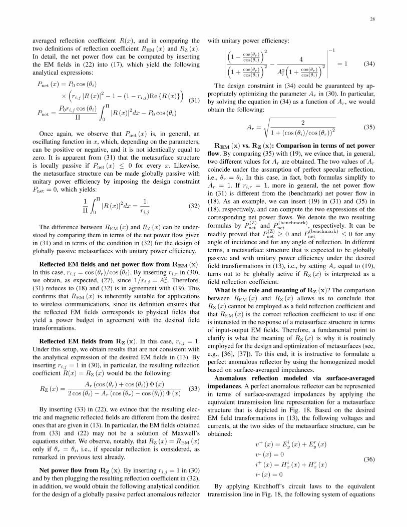
28
averaged reflection coefficient R(x), and in comparing thetwo definitions of reflection coefficient REM (x) and RZ (x).In detail, the net power flow can be computed by insertingthe EM fields in (22) into (17), which yield the followinganalytical expressions:
Pnet (x) = P0 cos (θi)
×(ri,j |R (x)|2 − 1− (1− ri,j)Re {R (x)}
)Pnet =
P0ri,j cos (θi)
Π
∫ Π
0
|R (x)|2dx− P0 cos (θi)
(31)
Once again, we observe that Pnet (x) is, in general, anoscillating function in x, which, depending on the parameters,can be positive or negative, and it is not identically equal tozero. It is apparent from (31) that the metasurface structureis locally passive if Pnet (x) ≤ 0 for every x. Likewise,the metasurface structure can be made globally passive withunitary power efficiency by imposing the design constraintPnet = 0, which yields:
1
Π
∫ Π
0
|R (x)|2dx =1
ri,j(32)
The difference between REM (x) and RZ (x) can be under-stood by comparing them in terms of the net power flow givenin (31) and in terms of the condition in (32) for the design ofglobally passive metasurfaces with unitary power efficiency.
Reflected EM fields and net power flow from REM (x).In this case, ri,j = cos (θr)/cos (θi). By inserting ri,r in (30),we obtain, as expected, (27), since 1
/ri,j = A2
r . Therefore,(31) reduces to (18) and (32) is in agreement with (19). Thisconfirms that REM (x) is inherently suitable for applicationsto wireless communications, since its definition ensures thatthe reflected EM fields corresponds to physical fields thatyield a power budget in agreement with the desired fieldtransformations.
Reflected EM fields from RZ (x). In this case, ri,j = 1.Under this setup, we obtain results that are not consistent withthe analytical expression of the desired EM fields in (13). Byinserting ri,j = 1 in (30), in particular, the resulting reflectioncoefficient R(x) = RZ (x) would be the following:
RZ (x) =Ar (cos (θr) + cos (θi)) Φ (x)
2 cos (θi)−Ar (cos (θr)− cos (θi)) Φ (x)(33)
By inserting (33) in (22), we evince that the resulting elec-tric and magnetic reflected fields are different from the desiredones that are given in (13). In particular, the EM fields obtainedfrom (33) and (22) may not be a solution of Maxwell’sequations either. We observe, notably, that RZ (x) = REM (x)only if θr = θi, i.e., if specular reflection is considered, asremarked in previous text already.
Net power flow from RZ (x). By inserting ri,j = 1 in (30)and by then plugging the resulting reflection coefficient in (32),in addition, we would obtain the following analytical conditionfor the design of a globally passive perfect anomalous reflector
with unitary power efficiency:∣∣∣∣∣∣∣(
1− cos(θr)cos(θi)
)2
(1 + cos(θr)
cos(θi)
)2 −4
A2r
(1 + cos(θr)
cos(θi)
)2
∣∣∣∣∣∣∣−1
= 1 (34)
The design constraint in (34) could be guaranteed by ap-propriately optimizing the parameter Ar in (30). In particular,by solving the equation in (34) as a function of Ar, we wouldobtain the following:
Ar =
√2
1 + (cos (θi)/cos (θr))2 (35)
REM (x) vs. RZ (x): Comparison in terms of net powerflow. By comparing (35) with (19), we evince that, in general,two different values for Ar are obtained. The two values of Arcoincide under the assumption of perfect specular reflection,i.e., θr = θi. In this case, in fact, both formulas simplify toAr = 1. If ri,r = 1, more in general, the net power flowin (31) is different from the (benchmark) net power flow in(18). As an example, we can insert (19) in (31) and (35) in(18), respectively, and can compute the two expressions of thecorresponding net power flows. We denote the two resultingformulas by P
(Z)net and P
(benchmark)net , respectively. It can be
readily proved that P (Z)net ≥ 0 and P
(benchmark)net ≤ 0 for any
angle of incidence and for any angle of reflection. In differentterms, a metasurface structure that is expected to be globallypassive and with unitary power efficiency under the desiredfield transformations in (13), i.e., by setting Ar equal to (19),turns out to be globally active if RZ (x) is interpreted as afield reflection coefficient.
What is the role and meaning of RZ (x)? The comparisonbetween REM (x) and RZ (x) allows us to conclude thatRZ (x) cannot be employed as a field reflection coefficient andthat REM (x) is the correct reflection coefficient to use if oneis interested in the response of a metasurface structure in termsof input-output EM fields. Therefore, a fundamental point toclarify is what the meaning of RZ (x) is why it is routinelyemployed for the design and optimization of metasurfaces (see,e.g., [36], [37]). To this end, it is instructive to formulate aperfect anomalous reflector by using the homogenized modelbased on surface-averaged impedances.
Anomalous reflection modeled via surface-averagedimpedances. A perfect anomalous reflector can be representedin terms of surface-averaged impedances by applying theequivalent transmission line representation for a metasurfacestructure that is depicted in Fig. 18. Based on the desiredEM field transformations in (13), the following voltages andcurrents, at the two sides of the metasurface structure, can beobtained:
v+ (x) = Eiy (x) + Ery (x)
v (x) = 0
i+ (x) = Hix (x) +Hr
x (x)
i (x) = 0
(36)
By applying Kirchhoff’s circuit laws to the equivalenttransmission line in Fig. 18, the following system of equations

29
can be obtained:{v+ (x) = (Z1 (x) + Z3 (x)) i+ (x) + Z3 (x) i− (x)
v− (x) = Z3 (x) i+ (x) + (Z2 (x) + Z3 (x)) i− (x)(37)
By inserting (36) in (37), we evince that a solution of thesystem of equations, i.e., an explicit expression of the surface-averaged impedances as a function of the transformations ofthe EM fields to be realized, is the following:
Z1 (x) = v+ (x)/i+ (x)
Z2 (x) = any function
Z3 (x) = 0
(38)
Therefore, Z1 (x) is the surface-averaged impedance thatdetermines the properties and EM response of the metasurfacestructure under design. By inserting (36) in (38) and using(13), in particular, the following benchmark analytical formu-lation for Z1 (x) can be obtained (for any value of Ar):
Z1 (x) =Eiy (x) + Ery (x)
Hix (x) +Hr
x (x)
= η1 +ArΦ (x)
cos (θi)−Ar cos (θi) Φ (x)
(a)=
η√cos (θi) cos (θr)
√cos (θr) +
√cos (θi)Φ (x)√
cos (θi)−√
cos (θr)Φ (x)
(39)
where (a) holds true if Ar is set equal to (19).Comparison of homogenized models. By direct inspection
of (39), we observe that: (i) Z1 (x) is, except for a scalingfactor, the same as the surface-averaged susceptibility functionin (14). This proves the equivalence of the homogenizedmodels based on susceptibilities and impedances; (ii) Z1 (x)coincides with the analytical formulations reported in [36],[37], [38], [39]. We note, in particular, that Z1 (x) is consistentwith the advanced design in [39, Eq. (3)], for which a practicalimplementation of metasurface based on the physical principleof leaky-wave antennas exists; and (iii) Z1 (x) is a complexnumber whose real part can be positive and negative. Thisbrings to our attention that the resulting metasurface structureis non-locally passive but it can be made globally passive ifAr is set equal to (19). An example of realization of a non-locally passive but globally passive metasurface that behavesas a perfect anomalous reflector is elaborated in further textbased on the recent results reported in [39].
Definition of RZ (x) based on surface-averagedimpedances. In the context of designing and engineeringmetasurfaces, the usual definition of surface-averaged reflec-tion coefficient is the following [36], [37], [38], [39]:
r (x) =Z1 (x)− η
cos(θi)
Z1 (x) + ηcos(θi)
(a)=Z1 (x)− Zi (x)
Z1 (x) + Zi (x)(40)
where (a) is obtained by using (25).By inserting (39) in (40), we obtain r (x) = RZ (x), where
RZ (x) is the surface-averaged reflection coefficient in (33).We conclude that RZ (x) is the surface-averaged reflectioncoefficient that is usually found in physics-related papers, andthat is typically employed for getting insights for designingmetasurface structures with the desired reflection capabilities.
Notably, RZ (x) fulfills the identities in (24), which aretypically employed as a definition of reflection coefficient inthe context of circuits design and analysis.
Physical interpretation and usefulness of RZ (x). Eventhough, as mentioned, RZ (x) is not appropriate for relating thereflected EM fields to the incident EM fields, it provides onewith important information for designing perfect anomalousreflectors. This can be inferred by a careful analysis of theequality (a) in (40). In a nutshell, r (x) = RZ (x) providesone with information on how different the local (or point-wise) responses of a perfect anomalous reflector and a perfectspecular reflector are. In general terms, according to (25)and (26), the impedances of the incident and reflected EMwaves are equal to Zi = η/cos (θi) and Zr = η/cos (θr),respectively. The larger the difference between the angle ofreflection and the angle of reflection is, therefore, the largerthe difference between Zi and Zr is. This implies that thetransformation of the EM fields applied by the metasurfacestructure needs to be more distinct and marked as the differ-ence between the angles of reflection and incidence increases.The reflection coefficient r (x) = RZ (x) is a parameter thatquantifies the local distinctive response of the metasurfacestructure. For a deeper understanding, let us assume that Aris equal to (19). The reflection coefficient r (x) = RZ (x) of aspecular reflector can be obtained from (40) by setting θr = θi,which yields r (x) = RZ (x) = 1 for every x. For a specularreflector, in other words, r (x) = RZ (x) is constant in x. Ifθr 6= θi, on the other hand, the amplitude of r (x) = RZ (x),i.e., |RZ (x)|, exhibits spatial variations in x, which becomesmore pronounced as the difference between the angle ofreflection and the angle of incidence increases. By inspectingr (x) = RZ (x), we obtain information on the mismatch ofthe local spatial responses of the metasurface structures thatcorrespond to anomalous and specular reflection. The specularreflector is a meaningful reference because it correspondsto the usual response of conventional surfaces and becauseit is characterized by an r (x) = RZ (x) that is a uniformfunction in x. It is worth noting that the reflection coefficientREM (x) is not capable of unveiling these properties. From(27), in particular, we evince that the amplitude of REM (x)exhibits no spatial variations along the metasurface structure,i.e., |REM (x)| = Ar is independent of x for any anglesof incidence and reflection. This confirms, once more, thatREM (x) and RZ (x) have different physical meanings andserve for different purposes. In the next paragraphs, numericalillustrations are used in order to further elucidate the proper-ties, differences, and similarities of REM (x) and RZ (x).
Canonical case: Normal incidence. In the rest of this sub-section, for simplicity but without loss of generality, we focusour attention on the canonical case of EM fields with normalincidence, i.e., θi = 0. In this case, REM (x) in (27) andRZ (x) in (33) reduce, respectively, to the following:
REM (x) = Ar exp (−jk sin (θr)x) (41)
RZ (x) =Ar (1 + cos (θr)) exp (−jk sin (θr)x)
2 +Ar (1− cos (θr)) exp (−jk sin (θr)x)(42)
In the following paragraph, as a case study, we describe

30
-2.5 -2 -1.5 -1 -0.5 0 0.5 1 1.5 2 2.5 x/λ
0.8
1
1.2
1.4
1.6
1.8
2
2.2 A
mpl
itude
of R
EM(x
) Ar = A2
θ = 30°
θ = 45°
θ = 75°
ray optics
Fig. 20: Amplitude of the reflection coefficient REM(x) in (41) forθr = θ. Dashed lines: Ray optics approximation (i.e., Ar = 1).
-2.5 -2 -1.5 -1 -0.5 0 0.5 1 1.5 2 2.5 x/λ
-4
-3
-2
-1
0
1
2
3
4
Pha
se o
f REM
(x)
Ar = A2
θ = 30°
θ = 45°
θ = 75°
ray optics
Fig. 21: Phase of the reflection coefficient REM(x) in (41) for θr = θ.Dashed lines: Ray optics approximation (i.e., Ar = 1).
some numerical illustrations in order to gain important engi-neering insights on the main features and properties of thereflection coefficients in (41) and (42) for various systemsetups and optimization criteria. It is worth emphasizing that(41) and (42) hold true for general values of Ar. The specificchoice of Ar determines, however, the ultimate performance,the power efficiency, and the implementation constraints forrealizing, in practice, the resulting metasurface structure.
Numerical illustrations: Understanding anomalous re-flection. Based on the closed-form expressions in (41) and(42), the amplitude and phase of the surface-averaged reflec-tion coefficient REM(x) are depicted in Figs. 20 and 21, andthe amplitude and phase of the surface-averaged reflectioncoefficient RZ(x) are depicted in Figs. 22-25, respectively,for different values of the angle of reflection θr and for twodifferent values of Ar: (i) Ar = A1 = 1 and (ii) Ar = A2
equal to (19) by setting θi = 0 in both cases. The consideredcase studies are relevant in order to understand the impactof Ar on the design of metasurfaces, and to clarify the
differences and similarities between REM(x) and RZ(x). Bydirect inspection of (41), (42), and Figs. 20-25, the followingimportant observations can be made.
• Designs based on ray optics are approximated. Thesurface-averaged reflection coefficients REM(x) andRZ(x) of a perfect anomalous reflector are complexnumbers whose amplitude and phase are, in general,different from those obtained by using ray optics ap-proximation, i.e., Rray optics (x) = exp (−jk sin (θr)x)[40]. In general, however, ray optics approximation issufficiently accurate for low-medium angles of reflection,θr, that need to be realized. It is worth nothing, inparticular, that REM(x) and RZ(x) tends, for every x, toone if θr = 0, i.e., if specular reflection is considered. Weobserve, however, a distinct difference between REM(x)and RZ(x). As far as REM(x) is concerned, Figs. 20 and21 show that the phase response of REM(x) coincide withray optics approximation but the amplitude of REM(x) isdifferent under the assumption that Ar is optimized forachieving unitary power efficiency (in the global sense).We observe, however, that the amplitude of REM(x)exhibits no spatial variations and it is constant in x.As far as RZ(x) is concerned, Figs. 22-25 unveil adifferent behavior as a function of x. The main differencestems from the amplitude of RZ(x), which exhibits ahighly varying spatial response whose fluctuations aremore pronounced as the angle of reflection increases(with respect to the angle of incidence). The highly non-uniform local behavior of RZ(x) unveils the inherentdifficulty of realizing perfect anomalous reflectors withlarge angles of deflection and high power efficiency.
• Amplitude and phase responses are correlated. For agiven angle of reflection, θr, the amplitude and phaseof REM(x) and RZ(x) are, in general, not independentof each other. The term “correlation” has, however, adifferent meaning for REM(x) and RZ(x). As far asREM(x) is concerned, the term correlation refers to thefact that the amplitude and phase of REM(x) depend onthe angle of reflection if Ar is equal to (19). In order tomaximize the power efficiency of a metasurface structure,this implies that the amplitude and phase of REM(x) can-not be set independently of each other. This amplitude-phase interplay is not captured by ray optics approxi-mation. However, no spatial coupling, i.e., as a functionof x, is observed because the amplitude of REM(x) isindependent of x. As far as RZ(x) is concerned, onthe other hand, the amplitude and phase of RZ(x) aretightly (spatially) correlated along the surface, i.e., as afunction of x. It is not possible, in general, to optimizethe amplitude and the phase of RZ(x) independently ofeach other. Similar to REM(x), the amplitude and phaseof RZ(x) depend on the angle of reflection. The highlynon-uniform spatial coupling between the amplitude andthe phase of RZ(x) unveils the inherent difficulty ofrealizing perfect anomalous reflectors with large anglesof deflection and high power efficiency.
• The surface reflection coefficients are periodic func-
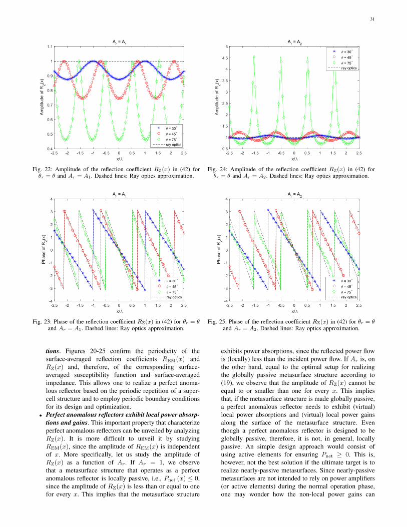
31
-2.5 -2 -1.5 -1 -0.5 0 0.5 1 1.5 2 2.5 x/λ
0.4
0.5
0.6
0.7
0.8
0.9
1
1.1 A
mpl
itude
of R
Z(x)
Ar = A1
θ = 30°
θ = 45°
θ = 75°
ray optics
Fig. 22: Amplitude of the reflection coefficient RZ(x) in (42) forθr = θ and Ar = A1. Dashed lines: Ray optics approximation.
-2.5 -2 -1.5 -1 -0.5 0 0.5 1 1.5 2 2.5 x/λ
-4
-3
-2
-1
0
1
2
3
4
Pha
se o
f RZ(x
)
Ar = A1
θ = 30°
θ = 45°
θ = 75°
ray optics
Fig. 23: Phase of the reflection coefficient RZ(x) in (42) for θr = θand Ar = A1. Dashed lines: Ray optics approximation.
tions. Figures 20-25 confirm the periodicity of thesurface-averaged reflection coefficients REM(x) andRZ(x) and, therefore, of the corresponding surface-averaged susceptibility function and surface-averagedimpedance. This allows one to realize a perfect anoma-lous reflector based on the periodic repetition of a super-cell structure and to employ periodic boundary conditionsfor its design and optimization.
• Perfect anomalous reflectors exhibit local power absorp-tions and gains. This important property that characterizeperfect anomalous reflectors can be unveiled by analyzingRZ(x). It is more difficult to unveil it by studyingREM(x), since the amplitude of REM(x) is independentof x. More specifically, let us study the amplitude ofRZ(x) as a function of Ar. If Ar = 1, we observethat a metasurface structure that operates as a perfectanomalous reflector is locally passive, i.e., Pnet (x) ≤ 0,since the amplitude of RZ(x) is less than or equal to onefor every x. This implies that the metasurface structure
-2.5 -2 -1.5 -1 -0.5 0 0.5 1 1.5 2 2.5 x/λ
0.5
1
1.5
2
2.5
3
3.5
4
4.5
5
Am
plitu
de o
f RZ(x
)
Ar = A2
θ = 30°
θ = 45°
θ = 75°
ray optics
Fig. 24: Amplitude of the reflection coefficient RZ(x) in (42) forθr = θ and Ar = A2. Dashed lines: Ray optics approximation.
-2.5 -2 -1.5 -1 -0.5 0 0.5 1 1.5 2 2.5 x/λ
-4
-3
-2
-1
0
1
2
3
4
Pha
se o
f RZ(x
)
Ar = A2
θ = 30°
θ = 45°
θ = 75°
ray optics
Fig. 25: Phase of the reflection coefficient RZ(x) in (42) for θr = θand Ar = A2. Dashed lines: Ray optics approximation.
exhibits power absorptions, since the reflected power flowis (locally) less than the incident power flow. If Ar is, onthe other hand, equal to the optimal setup for realizingthe globally passive metasurface structure according to(19), we observe that the amplitude of RZ(x) cannot beequal to or smaller than one for every x. This impliesthat, if the metasurface structure is made globally passive,a perfect anomalous reflector needs to exhibit (virtual)local power absorptions and (virtual) local power gainsalong the surface of the metasurface structure. Eventhough a perfect anomalous reflector is designed to beglobally passive, therefore, it is not, in general, locallypassive. An simple design approach would consist ofusing active elements for ensuring Pnet ≥ 0. This is,however, not the best solution if the ultimate target is torealize nearly-passive metasurfaces. Since nearly-passivemetasurfaces are not intended to rely on power amplifiers(or active elements) during the normal operation phase,one may wonder how the non-local power gains can

32
be obtained. This is discussed in, e.g., [37], [38], [39],[41]. The implementation recently reported in [39], whichassumes the optimal setup of Ar in (19), solves thisissue by proposing a metasurface design that is realizedby exciting evanescent (surface) waves (or leaky modes)that travel along the surface of the metasurface and thatcarry power from the effectively lossy regions to theeffectively active regions of the metasurface structure.In other words, the metasurface design in [39] excitesauxiliary EM fields, besides the propagating EM fieldstransformation in (13), so that (i) the energy of theimpinging radio wave travels along the surface, from the(virtual) lossy regions to the (virtual) active regions; (ii)the metasurface structure is kept globally passive and has(nearly) unitary power efficiency; and (iii) no or minimalspurious reflections are generated towards unwanted di-rections. Evanescent fields are, more precisely, oscillatingelectric and magnetic fields that do not propagate butwhose energy is spatially concentrated in the vicinity ofthe surface of the metasurface structure. The evanescentwaves decay exponentially and are appropriately designedso as not to interfere with the main functionality of themetasurface structure at distances of a few (typically twoor three) wavelengths from the metasurface. As far asthe practical implementation in [39] is concerned, thefields transformation in (13) constitutes, therefore, anapproximated model, since in the very close vicinity ofthe metasurface structure the EM fields are not givenby the summation of two simple incident and reflectedplane waves, but other evanescent EM fields need to beconsidered. For wireless applications, these evanescentEM fields can be ignored as a first approximation, sincethe distances of interest are usually larger than two-three wavelengths, both in the radiative near-field andin the far-field. This point is elaborated in further text.Figures 22-25 show, in particular, that the larger thereflection angle (with respect to the incident angle) is,the larger the (virtual) power absorptions and gains alongthe metasurface structure need to be. The optimal setupof Ar in (19), results, in addition, in larger fluctuations ofthe amplitude of RZ(x), which may be more difficult torealize in practice. No power fluctuation along the surfaceof the metasurface structure is obtained only if the angleof reflection coincides with the angle of incidence.
• On the global efficiency of perfect anomalous reflectors.The importance of realizing metasurfaces with a surface-averaged reflection coefficient REM(x) whose amplitudeis greater than one and with a surface-averaged reflec-tion coefficient RZ(x) whose amplitude exhibits localabsorptions and gains along the surface can be unveiledby analyzing the normalized net power flows reported inFigs. 26 and 27 for different values of Ar. In particular,Figs. 26 and 27 are obtained by employing the twoanalytical formulations of the net power flows in (18)and (31), respectively, for three different values of Ar:Ar = A1 = 1, Ar = A2 in (19), and Ar = A3 in(35). Negative and positive values of the normalized netpower flow imply that the metasurface structure exhibits
0 10 20 30 40 50 60 70 80 90 θ [°]
-1
-0.8
-0.6
-0.4
-0.2
0
0.2
Nor
mal
ied
Net
Pow
er F
low
Power flow - Benchmark and based on REM
Ar = A1Ar = A2Ar = A3
Fig. 26: Normalized net power flow (Pnet/P0) in (18) and (31), bysetting ri,r = cos (θr)/cos (θi), for θr = θ and Ar = {A1, A2, A3}.
0 10 20 30 40 50 60 70 80 90 θ [°]
-1
-0.5
0
0.5
1
1.5
2
Nor
mal
ized
Net
Pow
er F
low
Power flow - Based on RZ
Ar = A1Ar = A2Ar = A3
Fig. 27: Normalized net power flow (Pnet/P0) in (31), by settingri,r = 1, for θr = θ and Ar = {A1, A2, A3}.
global power absorptions and gains, respectively. Figure26 shows, in particular, that globally passive metasurfacescan be realized, based on (18), for all considered valuesof Ar. If Ar is set equal to (19), the metasurface structureis, as expected, globally passive and has a unitary powerefficiency. In general, however, the power efficiency de-creases as the angle of reflection (with respect to theangle of incidence) increases. From these results, weevince that highly efficient metasurface structures needto be non-locally passive. By setting Ar = 1, in fact,one can obtain a locally passive metasurface structure butits power efficiency is relatively low, especially for largevalues of the angle of reflection with respect to the angleof incidence. By analyzing Fig. 27, similar conclusionscan be made. However, Fig. 27 shows that the normalizednet power flow computed with (31) is greater than one ifAr is set equal to (19). This results confirms that RZ(x)is not an appropriate definition for the surface-averagedreflection coefficient if one is interested in calculating

33
the reflected EM fields from the incident EM fields.The corresponding power budget is, for example, notconsistent with the benchmark transformation of the EMfields in (13), which leads to different formulas for thenet power flow, as exemplified by comparing (18) with(31) by setting ri,r = 1.
REM (x) vs. RZ (x): Main takeaway message. Basedon the theoretical analysis and the numerical comparisonbetween REM (x) and RZ (x), it is apparent that they aretwo different parameters that serve for different purposes.In general, REM (x) = RZ (x) only for perfect specularreflectors. REM (x) is intended to be used in the of contextwireless communications in order to characterize the responseof a metasurface structure in terms of the phase andamplitude difference between the incident and reflectedEM fields. RZ (x) is intended to be used in the context ofmetasurface design in order to characterize the response of ametasurface structure in terms of the mismatch between theimpedances of the incident and reflected EM waves. BothREM (x) and RZ (x) are, however, surface-averaged, and,therefore, macroscopic parameters. As a consequence, it isnot appropriate to interpret either REM (x0) or RZ (x0) asthe response of an individual unit cell of the metasurfacestructure that is located in the point x0 on the surface. Thisis because REM (x) and RZ (x) are defined and calculatedbased on surface-averaged EM fields and are not based onacting (local) EM fields, as discussed in previous text.
Takeaway messages for application to wireless networks.Contrasting current models for RISs and the synthesisof metasurfaces. Several recently published papers (see,e.g., [21] and references therein) typically assume that anRIS can be modeled as a structure that is made of a discretenumber of individually tunable scatterers whose properties,e.g., the phase and amplitude of the reflection coefficient(i.e., REM (x)), can be arbitrary and individually controlled.In general, the amplitude of the reflection coefficient of eachscatterer is assumed to be unitary in order to ensure that theRIS is nearly-passive. Furthermore, the spatial correlationamong the individual scatterers is usually ignored. Theseassumptions may be considered to be sufficiently accurateif an RIS is made of discrete tiny antenna elements, similarto the prototype in Fig. 2, that are sufficiently distant fromeach other. The procedure for the synthesis of metasurfacesdescribed in this sub-section highlights, however, that theseconventional assumptions may not necessarily be appropriatefor modeling metasurfaces.
Key points to remember. In particular, the following keypoints need to be kept in mind when designing metasurface-based RIS-empowered wireless networks.
• The spatial coupling is not ignored. It is general beliefthat it is possible to individually control the reflectioncoefficient of each unit cell without taking into account-ing the mutual coupling among them. This may notnecessarily be correct. The synthesis procedure describedin this sub-section unveils that the mutual coupling is notexplicitly apparent thanks to the macroscopic description
of the metasurfaces through the surface-averaged suscep-tibility functions (or the surface-averaged impedances).The macroscopic description of metasurfaces originates,however, from a microscopic description that explicitlyaccounts for the mutual coupling via the local fields.From an implementation standpoint, a metasurface isrealized by jointly designing and optimizing the unitcells of the super-cell structure. This procedure inherentlyaccounts for the mutual coupling among the unit cells thatconstitute the super-cell.
• Globally passive does not imply locally passive. Nearly-passive RISs may not necessarily be locally passive. Ingeneral, highly-efficient metasurfaces may exhibit some(virtual) absorptions and gains along the surface.
• Amplitude and phase responses are intertwined. Theamplitude and phase of the radio waves impinging uponan RIS may not be modified independently of each other,but they may be coupled depending on the specific wavetransformations to be realized and the constraints imposedto realize locally passive or globally passive metasurfacestructures.
How to use the surface-averaged reflection coefficient. Asmentioned in previous text, the surface reflection coefficientfor modeling the scattering from objects is a widespread tool inthe context of wireless communications. Therefore, the analyt-ical formulation in (22) may be particular convenient to use. Inthe context of designing wireless communication systems andnetworks, it is important to emphasize that one is interestedin the surface-averaged reflection coefficient REM (x), whichprovides one with the response of a metasurface structurein terms of incident and reflected EM fields. The surface-averaged reflection coefficient REM (x) needs, however, notto be confused with the surface-averaged reflection coefficientRZ (x), which is often used for designing and for gaininginsight for implementing metasurface structures. Similar com-ments may be made if an RIS is employed for perfect anoma-lous transmission, or if it is designed to realize joint anomalousreflection and transmission. Based on these considerations,it is important to clarify how the surface-averaged reflectioncoefficient REM (x) should be used and should be interpretedin the context of wireless networks design. In this regard, thefollowing comments can be made.
• The surface-averaged reflection coefficient REM (x) isnot a local parameter. REM (x) is a surface-averagedparameter and, therefore, it is not appropriate to dis-cretize it and to interpret the resulting sampled valuesas the response of individual unit cells of the meta-surface structure. This is because REM (x) is definedand calculated based on surface-averaged EM fields andnot based on acting (local) EM fields. In this regard,REM (x) can be viewed as a “global” parameter thatcan be employed for analyzing RIS-empowered wirelessnetworks. In other words, the representation of an RISbased on REM (x) inherently hides the implementationdetails of the corresponding metasurface structure, but itprovides one with a tool to treat RISs as “black boxes”that can be used for designing and optimizing complex

34
wireless communication systems and networks.• Ar can be viewed as an optimization variable. The ana-
lytical formulation of the surface-averaged reflection co-efficient REM (x) is valid for any values of Ar. Therefore,one may restrict the range of values of Ar for the specificapplication of interest. More precisely, the parameter Arcan be viewed as an optimization parameter that allowsone to account for the interplay between power efficiencyand implementation complexity. If Ar = 1, in fact, themetasurface structure is easier to realize as comparedwith the setup of Ar equal to (19), since sophisticatedmetasurface structures that exhibit virtual power lossesand virtual power gains are needed in the latter case. Itis worth mentioning that Ar is, in general, a functionof the angles of incidence and reflection, as confirmedby (19). It is important to bear in mind, however, thatthe EM fields in (22) needs to be solutions of Maxwell’sequations. Ar and the corresponding reflected fields needto obey Maxwell’s equations, and, therefore, some (phys-ical) constraints on their choice exist.
• Ar can be greater than one. Conventional methods formodeling RISs in wireless communications are basedon representing an RIS through a diagonal matrix withindividually tunable reflecting elements whose amplitudesare all unitary and are independent of the applied phaseshifts [21]. This modeling approach corresponds to usingREM (x) in (27) by setting Ar = 1. The resultingmetasurface structure is inherently locally passive butsub-optimal from the power efficiency point of view.In general, Ar is greater than one in globally passivemetasurfaces and it depends on the angles of incidenceand reflection.
“Black box” modeling of a perfect anomalous reflector.Based on the described synthesis procedure and recipe forapplication to wireless networks, therefore, we can modelan RIS that is designed to operate as a perfect anomalousreflector as a “black box” whose output field is obtained bymultiplying the input field and the surface-averaged reflectioncoefficient REM (x) in (27), as formulated in (22). This simpleprocedure allows one to account for several practical aspectsof a metasurface, which include the mutual coupling amongindividual unit cells and the fact that, with the exception ofthe configuration network, the RIS is globally passive eventhough it is not necessarily locally passive. Further detailson the analysis of general metasurfaces are given in the nextsub-section. It is worth anticipating, however, that modeling aperfect anomalous reflector by means of a surface reflectioncoefficient relies on the assumption that the incident EM fieldscan be approximated to be locally-plane waves at the scale ofan individual unit cell (not necessarily at the scale of the entiremetasurface). Usually, this can be considered to be true atdistances from the metasurface structure that are greater thana few (two or three) wavelengths. From the physics standpoint,this is necessary since the surface reflection coefficient definedin the present paper does not account for the evanescent EMwaves in close vicinity of the metasurface, which may beneeded to realize non-local passive structures. This concept
is illustrated in Fig. 29 and it is further elaborated in the nextsub-section.
Relevance of the surface-averaged reflection coefficientfor wireless applications. The analytical formulation in termsof surface-averaged reflection coefficient REM (x) is espe-cially useful for wireless applications. The reason is thatwireless researchers are used to model systems as black boxesthat perform some specific functions, but, at the same time,they wish to hide unnecessary details related to the practicalimplementation and realization of the systems themselves.This is necessary for analytical tractability, in order to modeland optimize complex wireless networks, in which a singlemetasurface is one of the many network elements. Withthis in mind, the representation of EM fields as a functionof surface-averaged susceptibility functions, surface-averagedimpedances, or surface-averaged reflection coefficient RZ (x)do not yield an explicit analytical formulation of the out-put fields as a function of the input fields. These latterhomogenized representations, however, explicitly depend onthe physical structure of the metasurface itself. This is usefulfor the synthesis of metasurfaces, since important insights onpractical structures of unit cells can be explicitly obtained,and design guidelines on realizing practical structures can beobtained (e.g., from RZ (x)). The representation in terms ofsurface-averaged reflection coefficient REM (x) provides, onthe other hand, information only on the function realized bya metasurface from the global point of view while hidingimplementation-related details. Concretely, REM (x) providesone with an explicit relation that depends only on the angleof incidence and reflection of the radio waves, while hidingthe physical structure of the metasurface. At the same time,the analytical formulation of REM (x) in (27) overcomes thelimitations of current models used for wireless applications,according to which REM (x1) and REM (x2) are optimizedindependently of each other for any x1 6= x2 [21].
5) Analysis of a Metasurface: EM fields scattered bya given metasurface. In the previous sub-section, we havereported a general procedure for the synthesis of a metasurfacethat needs to realize some specified transformations on theimpinging radio waves. In this sub-section, on the other hand,we consider that the metasurface is given and we are interestedin computing a general and explicit expression of the reflectedand transmitted electric and magnetic fields for some givenincident electric and magnetic fields. In particular, we focusour attention on the EM fields that are at the two sides ofa metasurface, i.e., at z = 0+ and z = 0−, which are theresult of the EM discontinuity introduced by the metasurfacestructure. They are referred to as surface EM fields. Thecomputation of the electric and magnetic fields at any arbitrarypoint of a given volume where a metasurface is deployed are,on the other hand, discussed in the next sub-section.
Surface EM fields. The analytical expressions of thesurface EM fields that we are interested in calculating canbe obtained from the GSTCs in (9) and (10). In order toobtain an explicit expression of every tangential componentof the electric and magnetic fields, we introduce the followingmatrices (for ease of writing, the dependency on (x, y) is not
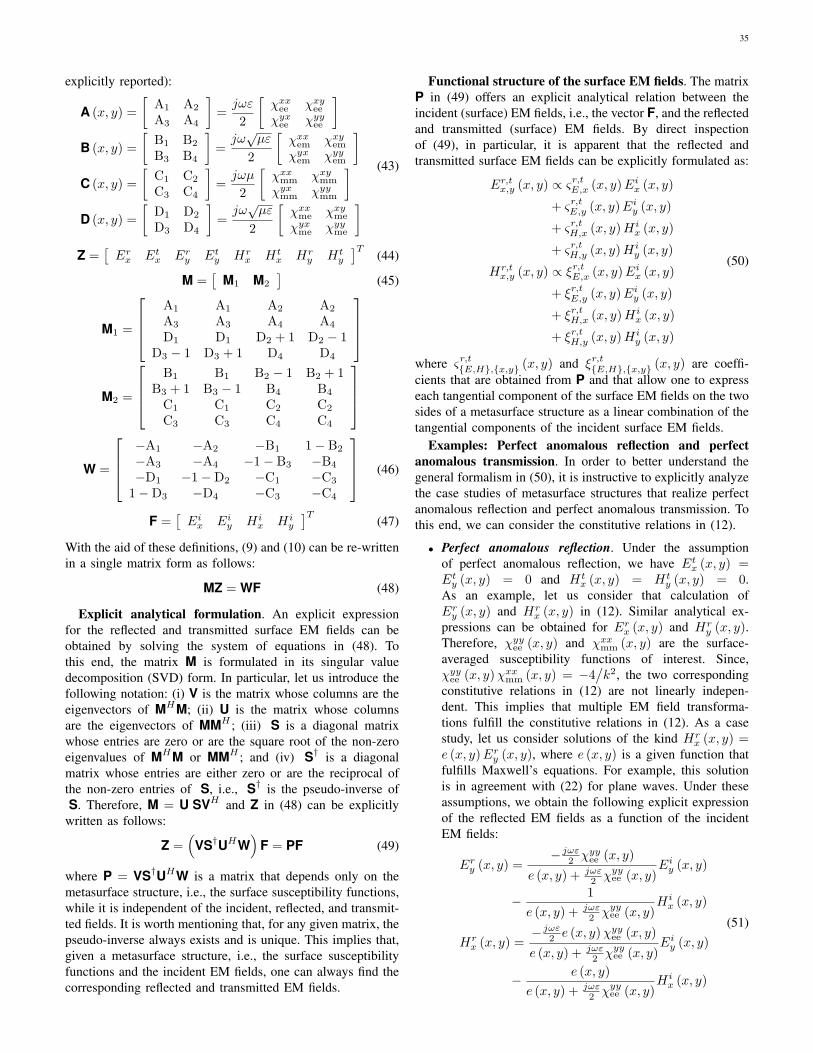
35
explicitly reported):
A (x, y) =
[A1 A2
A3 A4
]=jωε
2
[χxxee χxyee
χyxee χyyee
]B (x, y) =
[B1 B2
B3 B4
]=jω√µε
2
[χxxem χxyem
χyxem χyyem
]C (x, y) =
[C1 C2
C3 C4
]=jωµ
2
[χxxmm χxymm
χyxmm χyymm
]D (x, y) =
[D1 D2
D3 D4
]=jω√µε
2
[χxxme χxyme
χyxme χyyme
](43)
Z =[Erx Etx Ery Ety Hr
x Htx Hr
y Hty
]T(44)
M =[
M1 M2
](45)
M1 =
A1 A1 A2 A2
A3 A3 A4 A4
D1 D1 D2 + 1 D2 − 1D3 − 1 D3 + 1 D4 D4
M2 =
B1 B1 B2 − 1 B2 + 1
B3 + 1 B3 − 1 B4 B4
C1 C1 C2 C2
C3 C3 C4 C4
W =
−A1 −A2 −B1 1− B2
−A3 −A4 −1− B3 −B4
−D1 −1−D2 −C1 −C3
1−D3 −D4 −C3 −C4
(46)
F =[Eix Eiy Hi
x Hiy
]T(47)
With the aid of these definitions, (9) and (10) can be re-writtenin a single matrix form as follows:
MZ = WF (48)
Explicit analytical formulation. An explicit expressionfor the reflected and transmitted surface EM fields can beobtained by solving the system of equations in (48). Tothis end, the matrix M is formulated in its singular valuedecomposition (SVD) form. In particular, let us introduce thefollowing notation: (i) V is the matrix whose columns are theeigenvectors of MHM; (ii) U is the matrix whose columnsare the eigenvectors of MMH ; (iii) S is a diagonal matrixwhose entries are zero or are the square root of the non-zeroeigenvalues of MHM or MMH ; and (iv) S† is a diagonalmatrix whose entries are either zero or are the reciprocal ofthe non-zero entries of S, i.e., S† is the pseudo-inverse ofS. Therefore, M = U SVH and Z in (48) can be explicitly
written as follows:
Z =(
VS†UHW)
F = PF (49)
where P = VS†UHW is a matrix that depends only on themetasurface structure, i.e., the surface susceptibility functions,while it is independent of the incident, reflected, and transmit-ted fields. It is worth mentioning that, for any given matrix, thepseudo-inverse always exists and is unique. This implies that,given a metasurface structure, i.e., the surface susceptibilityfunctions and the incident EM fields, one can always find thecorresponding reflected and transmitted EM fields.
Functional structure of the surface EM fields. The matrixP in (49) offers an explicit analytical relation between theincident (surface) EM fields, i.e., the vector F, and the reflectedand transmitted (surface) EM fields. By direct inspectionof (49), in particular, it is apparent that the reflected andtransmitted surface EM fields can be explicitly formulated as:
Er,tx,y (x, y) ∝ ςr,tE,x (x, y)Eix (x, y)
+ ςr,tE,y (x, y)Eiy (x, y)
+ ςr,tH,x (x, y)Hix (x, y)
+ ςr,tH,y (x, y)Hiy (x, y)
Hr,tx,y (x, y) ∝ ξr,tE,x (x, y)Eix (x, y)
+ ξr,tE,y (x, y)Eiy (x, y)
+ ξr,tH,x (x, y)Hix (x, y)
+ ξr,tH,y (x, y)Hiy (x, y)
(50)
where ςr,t{E,H},{x,y} (x, y) and ξr,t{E,H},{x,y} (x, y) are coeffi-cients that are obtained from P and that allow one to expresseach tangential component of the surface EM fields on the twosides of a metasurface structure as a linear combination of thetangential components of the incident surface EM fields.
Examples: Perfect anomalous reflection and perfectanomalous transmission. In order to better understand thegeneral formalism in (50), it is instructive to explicitly analyzethe case studies of metasurface structures that realize perfectanomalous reflection and perfect anomalous transmission. Tothis end, we can consider the constitutive relations in (12).
• Perfect anomalous reflection. Under the assumptionof perfect anomalous reflection, we have Etx (x, y) =Ety (x, y) = 0 and Ht
x (x, y) = Hty (x, y) = 0.
As an example, let us consider that calculation ofEry (x, y) and Hr
x (x, y) in (12). Similar analytical ex-pressions can be obtained for Erx (x, y) and Hr
y (x, y).Therefore, χyyee (x, y) and χxxmm (x, y) are the surface-averaged susceptibility functions of interest. Since,χyyee (x, y)χxxmm (x, y) = −4
/k2, the two corresponding
constitutive relations in (12) are not linearly indepen-dent. This implies that multiple EM field transforma-tions fulfill the constitutive relations in (12). As a casestudy, let us consider solutions of the kind Hr
x (x, y) =e (x, y)Ery (x, y), where e (x, y) is a given function thatfulfills Maxwell’s equations. For example, this solutionis in agreement with (22) for plane waves. Under theseassumptions, we obtain the following explicit expressionof the reflected EM fields as a function of the incidentEM fields:
Ery (x, y) =− jωε2 χyyee (x, y)
e (x, y) + jωε2 χyyee (x, y)
Eiy (x, y)
− 1
e (x, y) + jωε2 χyyee (x, y)
Hix (x, y)
Hrx (x, y) =
− jωε2 e (x, y)χyyee (x, y)
e (x, y) + jωε2 χyyee (x, y)
Eiy (x, y)
− e (x, y)
e (x, y) + jωε2 χyyee (x, y)
Hix (x, y)
(51)

36
• Perfect anomalous transmission. Under the assumptionof perfect anomalous transmission, we have Erx (x, y) =Ery (x, y) = 0 and Hr
x (x, y) = Hry (x, y) = 0. As an
example, let us consider that calculation of Ety (x, y) andHtx (x, y). Similar analytical expressions can be obtained
for Etx (x, y) and Hty (x, y). Therefore, χyyee (x, y) and
χxxmm (x, y) are the surface-averaged susceptibility func-tions of interest. Under these assumptions, we obtain thefollowing explicit expression of the transmitted EM fieldsas a function of the incident EM fields:
Ety (x, y) =1 + jωε
2 χyyee (x, y) jωµ2 χxxmm (x, y)
1− jωε2 χyyee (x, y) jωµ2 χxxmm (x, y)
Eiy (x, y)
+ 2jωµ
2 χxxmm (x, y)
1− jωε2 χyyee (x, y) jωµ2 χxxmm (x, y)
Hix (x, y)
Htx (x, y) = 2
jωε2 χyyee (x, y)
1− jωε2 χyyee (x, y) jωµ2 χxxmm (x, y)
Eiy (x, y)
+1 + jωε
2 χyyee (x, y) jωµ2 χxxmm (x, y)
1− jωε2 χyyee (x, y) jωµ2 χxxmm (x, y)
Hix (x, y)
(52)
In both case studies, we note that the transmitted electricand magnetic fields are expressed as a linear combination ofboth the incident electric and magnetic fields. In general, inother words, cross-coupling among the EM fields exist.
“Black box” modeling of metasurfaces. Based on thesegeneral considerations and specific examples, the main conclu-sion that can be drawn from (49) is that a metasurface can bemodeled as a “black box” that takes the electric and magnetic(surface-averaged) EM fields in F at its input and yields asan output the (surface-averaged) EM fields in Z. The exampleof perfect anomalous reflector analyzed in the previous sub-section is a special case of the general analytical formulationin (49), in which many entries of the surface susceptibilitymatrices are equal to zero by design. From a conceptual pointof view, ςr,·{·},{·} (x, y) and ξr,·{·},{·} (x, y) can be interpretedas surface-averaged reflection coefficients (i.e., REM (x)) andςt,·{·},{·} (x, y) and ξt,·{·},{·} (x, y) as surface-averaged transmis-sion coefficients for specific pairs of tangential components ofthe surface-averaged electric and magnetic fields on the twosides of the metasurface. As remarked in the previous sub-section, these coefficients implicitly account for the mutualcoupling among the unit cells of the metasurface, as well asfor the inherent coupling between the phase response and theamplitude response of the surface susceptibility functions. Itis important to point out, however, that the surface-averagedEM fields under consideration can, in principle, be measuredat distances from the metasurface that are larger than oftwo-three times the size of a unit cell (see also Fig. 29discussed in further text). The EM fields in close vicinity ofthe metasurface may contain, on the other hand, significantevanescent-field content that is carefully optimized in thedesign of the super-cell structure. As far as the calculationof the EM fields scattered by a metasurface is concerned,however, it is sufficient to consider the surface-averaged EMfields that are obtained from the homogenized modeling ofmetasurfaces and that are formulated in terms of surface
Fig. 28: System model for modeling the propagation of radio wavesin the presence of metasurfaces.
susceptibility functions or surface impedances. This modelingassumption is employed in the next sub-section to formulatethe EM field scattered by a phase gradient metasurface.
Relation between synthesis and analysis. It is worthmentioning and emphasizing that the synthesis and analysis ofmetasurfaces are strongly intertwined. As far as the synthesis isconcerned, the metasurface structure is designed and optimizedbased on some given EM fields and desired radio wave trans-formations. This implies that, once the metasurface structure ismanufactured and deployed, it will realize the desired responseif the impinging radio waves have the same properties asthose assumed during the design and synthesis. Otherwise, theefficiency of the metasurface structure will be reduced and theactual response of the metasurface structure will be differentfrom the desired response. Similar comments apply to theanalysis and performance evaluation of wireless networks fora given metasurface structure. The surface susceptibility func-tions, in fact, correspond to incident, reflected, and transmittedEM fields with specific properties, e.g., the radio waves areplane, spherical, have a specified polarization, or simply aresupposed to impinge upon the metasurface at only some anglesof incidence. These constraints need to be taken into accountwhen analyzing and optimizing RIS-empowered SREs.
Beyond surface EM fields. The general functional relationsin (49) constitute the departing point in order to compute theelectric and magnetic fields at any point of a given volume,e.g., far away from a metasurface, where an RIS may bedeployed. This issue is investigated in the next sub-section.
D. On Modeling Radio Wave Propagation in the Presence ofMetasurfaces
From surface EM fields to EM fields in volumes. Inthe previous sub-section, we have shown that a metasurfacecan be described in terms of surface susceptibility functionsand that the electric and magnetic (surface) fields scattered bythe metasurface can be formulated in an algebraic form undersufficiently general modeling assumptions. In this sub-section,we show that the knowledge of the EM field at the two sidesof a metasurface, i.e., only at z = 0+ and z = 0−, is sufficientfor computing the EM field at any point of a given volume.
Reference system model. We summarize, in particular, theanalytical approach recently reported in [42]. We highlightonly the most important aspects of [42], some of which are

37
Fig. 29: Near-field vs. far-field of a metasurface and far-field of thearray microstructure. The far-field boundary of the metasurface isobtained from the Fraunhofer distance as illustrated in Figs. 7 and 8.
not extensively elaborated in the original paper. For simplicity,in addition, we restrict the analysis to a one-dimensionalmetasurface and to a two-dimensional space (i.e., the plane).The general case study that encompasses two-dimensionalmetasurfaces in a three-dimensional space can be found in[43]. For ease of illustration, the system model under analysisis sketched in Fig. 28, which depicts an infinitesimal smallsource that radiates isotropically in the plane and a one-dimensional metasurface. Further details about the systemmodel are given in further text.
Reference operating regimes. Before introducing the mainrecipe for obtaining the EM field scattered by a metasurface,we feel important to introduce some relevant operating regimesand concepts. To help us clarify them, the illustrations in Figs.29 and 30 are utilized.
• Near-field vs. far-field. As depicted in Fig. 4, a metasur-face is made of unit cells whose size is usually smallerthan the wavelength of the impinging radio waves. Atdistances from the metasurface that are larger than two-three times the size of a unit cell, which is still smallcompared with the wavelength, the EM fields of theevanescent surface modes of the metasurface structure,which may be present, can be considered to be negligiblealready. From the macroscopic point of view, in partic-ular, the radio waves impinging upon a metasurface canbe assumed to be locally plane waves regardless of theactual characteristics of the source (e.g., the source maynot necessarily emit plane waves). In simple terms, thisimplies that, e.g., a spherical wavefront impinging upona unit cell can be approximated by its tangent providedthat the size of the unit cell is sufficiently small that thephase of the impinging radio wave does not change alongthe unit cell. Since we are interested in EM fields that areevaluated at transmission distances from the metasurfacethat are larger than two-three times the size of a unit cell,we can ignore the evanescent fields that may be presentalong the metasurface structure, and we can utilize thesurface-averaged reflection coefficient for locally planewaves. In the present paper, this region is referred toas “the far-field of the array microstructure”. Physically,as mentioned, this region corresponds to distances from
Fig. 30: Electrically large vs. electrically small metasurfaces.
the metasurface structure at which the evanescent EMfields are negligible. If we consider the example of ananomalous perfect reflector, this implies that the EM fieldscattered by the metasurface is approximately equal tothe sum of two plane waves (as modeled in the previousexample). At these distances, one can define and usethe surface-averaged reflection coefficient REM (x) asdefined in the previous example. As far as the wholemetasurface structure is concerned, on the other hand,the operating regime is not unique. The transverse sizeof a metasurface can, in fact, be tens or hundreds (ormore) times larger than the wavelength of the impingingradio waves. This implies that it is not possible to ignore,in general, the phase change of the impinging radiowaves along the entire metasurface. Depending on theactual network geometry, the size of the metasurface,the operating wavelength, therefore, a metasurface canoperate either in the near-field regime or in the far-field regime. For clarity, these operating regimes areconceptually illustrated in Fig. 29.
• Electrically large and electrically small metasurfaces.As mentioned, we cannot assume, a priori, that a meta-surface operates in the far-field regime. This impliesthat the signal models and the corresponding analyticalframeworks need to be sufficiently general to take thisinto account. This can be considered to be a not so usualsituation in mainstream wireless communications, wherethe far-field operating regime is usually de facto implied,even though often not explicitly stated. In the presentpaper, we do not attempt to give a formal definition ofnear-field and far-field for a metasurface as a whole. Asan illustrative example, and based on the conventionaldefinition for active antennas, Figs. 7 and 8 report theboundary of the radiative near-field and far-field as com-puted from the Fraunhofer distance. We provide, on theother hand, arguments to distinguish these two operatingregimes from a practical standpoint. Instead of using theterms near-field and far-field, we introduce the conceptsof electrically large and electrically small metasurfaces.For clarity, these two concepts are illustrated in Fig.30. A metasurface is referred to as electrically largeif its geometric size is large enough as compared withthe wavelength of the radio waves, and as comparedwith the transmission distance from the source to themetasurface and from the metasurface to the observationpoint. If this is not the case, then the metasurface is

38
Fig. 31: The Huygens-Fresnel principle.
referred to as electrically small. The term “large enough”is deliberately left a bit vague, since a formal definitionwould depend on a large number of system parameters.In simple terms, based on Fig. 30, a metasurface canbe considered to be electrically large if the size of ametasurface and the transmission distances are such thatone sees the metasurface as being infinitely large, and,therefore, one cannot see the edges of the metasurfacestructure. If the opposite holds true, a metasurface canbe considered to be electrically small. By consideringa metasurface of a given and fixed size, with a similarline of thought, a metasurface can likely be consideredto be electrically large if the transmission distances aresufficiently short. If the transmission distances are, onthe other hand, sufficiently long, then a metasurface canlikely be considered to be electrically small. In furthertext, we show that the scaling laws as a function ofkey system parameters, e.g., the size of the metasurfaceand the transmission distances, are usually different forelectrically large and electrically small metasurfaces.
Theory of diffraction and Huygens-Fresnel principle.With these preliminary definitions at hand, we can now discusshow to appropriately model the propagation of radio waves inthe presence of a metasurface. As recently proved in [42] and[43], the EM field at any point of a volume and in the presenceof a metasurface can be obtained by invoking the theoryof diffraction and the Huygens-Fresnel principle. In generalterms, the theory of diffraction provides one with the math-ematical tools for modeling the bending of the radio waveswhen they encounter an object or a discontinuity, which inour case is a metasurface characterized by its specific effectiveparameters. In classical physics, more precisely, diffraction-based phenomena, including the reflection and transmissionfrom objects, are described by the Huygens-Fresnel principle.According to this principle, every point of a propagatingwavefront is viewed as a collection of individual sphericalwavelets. In particular, every point on a wavefront is itselfthe source of spherical wavelets, and the secondary waveletsemanated from different points interfere with each other.The sum of the emanated spherical wavelets forms a newwavefront. This concept is sketched in Fig. 31.
Green’s theorem. When the radio waves emitted by asource impinge upon a metasurface, based on the Huygens-Fresnel principle, the wavefront of the impinging radio wavein correspondence of a metasurface, i.e., at each point ofa metasurface, becomes the source of secondary waveletsthat determine the EM field at any point of the volume ofinterest. Based on the divergence theorem (or, its more generalformulation, the Green theorem [44]), which states that thesurface integral of a vector field over a closed surface is equalto the volume integral of the divergence of the vector fieldover the region inside the surface, the EM field of interestis uniquely determined by the EM fields on the two sidesof a metasurface, i.e., the surface EM fields. The readers arereferred to [42], [43] for the analytical details. As far as thepresent paper is concerned, it is sufficient to understand thatthis implies that the EM field at any point of a volume canbe obtained from the GSTCs computed in the previous sub-section, which, in fact, formulate the tangential componentsof the EM (surface) fields at the two sides of a metasurface.Formally, this is reported in (50) for a general metasurface.
The atomic case study. In the rest of the present paper,we assume, for simplicity, that the metasurface under analysisis characterized by a single non-zero reflection coefficientςr,·{·},{·} (x, y) = ∆ (x, y) exp (jkΥ (x, y)), where ∆ (x, y) =∣∣∣ςr,·{·},{·} (x, y)
∣∣∣ and kΥ (x, y) = arg(ςr,·{·},{·} (x, y)
)are the
amplitude and the phase of ςr,·{·},{·} (x, y). Also, we assume∆ (x, y) = ∆ (x) and Υ (x, y) = Υ (x). If other coefficients in(50) are not equal to zero, the electric or magnetic tangentialcomponents of the field of interest can be formulated as alinear combination of integrals similar to those reported infurther text. It is worth emphasizing that the term surface-averaged reflection coefficient is always referred to REM (x)(not to RZ (x)) if one is interested in analyzing the actual EMfields reflected from an RIS.
1) Analytical Formulation of the EM Field: An approachbased on Green’s functions. By capitalizing on the Huygens-Fresnel principle and by assuming an infinitesimally smallsource whose complex amplitude is the Green function ina two-dimensional plane, the authors of [42] have given thefollowing expression for a generic component of the EM fieldreflected by a metasurface located at y = 0 and Lx ≤ x ≤ Lx:
Z (xR, yR) ≈ 1
8π
∫ +Lx
−Lx
I (x) exp (−jkP (x)) dx
P (x) = dT (x) + dR (x)−Υ (x)
I (x) =∆ (x)√
dT (x) dR (x)
(yT
dT (x)+
yRdR (x)
) (53)
where 2Lx is the size (length) of the metasurface, (xT , yT )is the location of the source, (xR, yR) is the location of theobservation point (e.g., where an intended receiver is located),and dT (x) and dR (x) are the transmission distances from thesource to the point x of the metasurface and from the point xof the metasurface to the observation point, respectively:
dT (x) =
√(xT − x)
2+ y2
T
dR (x) =
√(xR − x)
2+ y2
R
(54)

39
It is worth mentioning that the integral (instead of a sumof EM fields scattered by individual scatterers) formulation in(53) is a consequence of employing a homogenized approachfor modeling metasurfaces, which is consistent with the sub-wavelength inter-distance between adjacent unit cells and theGSTCs introduced in the previous section.
Interpretation of the reflected field. The analytical formu-lation in (53), based on the Huygens-Fresnel principle, can beinterpreted by rewriting the integrand function as follows:
I (x) exp (−jkP (x)) =exp (−jkdT (x))√
dT (x)
×∆ (x) exp (jkΥ (x))
× exp (−jkdR (x))√dR (x)
×(
yTdT (x)
+yR
dR (x)
)(55)
where: (i) the first term corresponds to the radio wave im-pinging upon the metasurface (i.e., the Green function); (ii)the second term corresponds to the surface response of themetasurface that is obtained from the homogenized model;(iii) the third term corresponds to the radio wave that is re-emitted by the metasurface upon reception of the impingingradio wave (i.e., the Green function); and (iv) the fourth termrepresents the sum of the cosines of the inclination anglesunder which the metasurface is viewed by the source and bythe observation point. Finally, the integral originates from thefact that a metasurface can be homogeneized and by applyingthe divergence theorem, which, in simple terms, allows oneto formulate a vector field in a given volume as a function ofthe corresponding surface integral. It is worth mentioning thatI (x) depends on the square root of the transmission distancesbecause a bi-dimensional system model is considered, andthe amplitude of the corresponding Green function, in theabsence of a metasurface, decays with the square root of thetransmission distance.
2) Configuration of the Metasurface: Beamsteering vs.focusing. From (53), it is apparent that a metasurface can beappropriately configured and can perform different functionsdepending on the specific choice of ∆ (x) and Υ (x). Asillustrative examples, we consider three case studies thathave important applications in wireless communications: (i)specular reflector (or specular beamsteering); (ii) anomalousreflector (or anomalous beamsteering); and (iii) focusing lens(or beamforming). We assume, for simplicity, ∆ (x) = 1,which corresponds to a benchmark for the three configurationsof the metasurface under analysis.• Specular reflector. The specified wave transformation
that the metasurface needs to realize is reflection bymodifying the phase of the impinging radio wave. Thisoperation can be obtained by using a uniform metasurfacewhose phase response per unit length is as follows:
Υ (x) = φ0/k (56)
where φ0 ∈ [0, 2π) is a fixed phase shift. If φ0 = π, forexample, a perfect electric conductor (PEC) is obtained,whose reflection coefficient is −1.
Specular Reflector
-2 0 2 4 6 8 10x [m]
10
9
8
7
6
5
4
3
2
1
0
y [m
]
Anomalous Reflector
-2 0 2 4 6 8 10x [m]
10
9
8
7
6
5
4
3
2
1
0
y [m
]
Focusing Lens
-2 0 2 4 6 8 10x [m]
10
9
8
7
6
5
4
3
2
1
0
y [m
]
1
2
3
4
5
6
7
8
9
×10-3
Fig. 32: Comparison among specular reflector, anomalous reflector,and focusing lens (reproduced from [42]). The source is not reported
for clarity.
• Anomalous reflector. The specified wave transformationthat the metasurface needs to realize is reflection bymodifying the angle of reflection and the phase of theimpinging radio wave. This operation can be obtained byusing a phase gradient metasurface whose phase responseper unit length is as follows:
Υ (x) =(φT − φR
)x+ φ0/k (57)
where φ0 ∈ [0, 2π) is a fixed phase shift, and φT andφR are two parameters to be optimized in order to steerthe impinging radio wave towards a specified angle ofreflection. In [42], for example, φT and φR are optimizedas a function of the angles under which the source and thereceiver view the center of the metasurface. It is worthmentioning that the design of the phase gradient in (57)can be considered to be an approximation of the optimalreflector in (30) that originates from ray optics arguments.The numerical results in [42] show, however, that thedesired function is appropriately realized, even thoughthe efficiency of the metasurface, i.e., the ratio betweenthe reflected and incident powers, may not necessarily beoptimized.
• Focusing lens. The specified wave transformation thatthe metasurface needs to realize is focusing the impingingradio wave towards a specified location. This operationcan be obtained by using a phase gradient metasurfacewhose phase response per unit length is as follows:
Υ (x) =
√(x− xT )
2+ y2
T +
√(x− xR)
2+ y2
R (58)
where (xR, yR) is the location where the radio waveneeds to be focused.
Optimization criteria for beamsteering and focusing. Weobserve, therefore, that the phase response of the metasurfacestructure under analysis is quite different depending on thespecified function to be realized. As an example, we cananalyze the differences between the two phase responses

40
in (57) and (58). In simple terms, the criterion employedfor obtaining (57) consists of ensuring that, as a first-orderapproximation, the first-order derivative of P(x) in (53) isequal to zero in correspondence of those points, x, of themetasurface for which the angle of reflection is the desiredone (assuming that the angle of incidence is given and fixed).The criterion employed for obtaining (58) consists, on theother hand, of ensuring that P(x) in (53) is equal to zero incorrespondence of the location where the radio wave needs tobe focused to. By using this criterion, in fact, the complexterms as a function of x in (53) are all co-phased at thelocation of interest, thus yielding the desired focusing effect. Inconclusion, we can state that (57) is chosen by considering thestationary points of P(x), while (58) is chosen by consideringthe zeros of P(x). An example of the different behavior of theconsidered metasurface structure based on the configurationsspecified by the phase responses in (56), (57), and (58) isillustrated in Fig. 32.
Comparing metasurfaces obtained from different opti-mization criteria. Based on these considerations, we concludethat, in general, the performance of a metasurface is differentdepending on the criterion employed for optimizing P(x).This implies that it may not be relevant or interesting tofirst optimize a metasurface for operating as, e.g., a focusinglens, and then to study when and if the same metasurfacecan operate as an anomalous reflector. This is because thetwo metasurfaces are designed based on different criteriaand in order to perform different functions. Furthermore, thecomparison may not necessarily be fair since different designsusually rely on a different amount of channel state informationand on different implementation complexities. As an example,let us consider the realization and practical operation of ametasurface with the phase response in (57) and a metasurfacewith the phase response in (58). In the first case, one needs toknow only the angle of incidence and the angle of reflectionfor optimizing the phase response. This implies that the designneeds not to be changed if, e.g., a receiver moves along thesame direction. This could be true if, e.g., a user movesalong a street or a hallway. In the second case, on the otherhand, the optimization of (58) necessitates the exact locationof the receiver. This implies that the metasurface needs tobe reconfigured every time that the user moves, even thoughthe direction of motion is kept the same. This imposes somepractical constraints on the rate at which a metasurface needsto be reconfigured, and the rate at which the environmentalinformation needs to be estimated in order to achieve goodperformance.
3) Electrically Large vs. Electrically Small Regimes: Scal-ing laws and performance trends. In this sub-section, weanalyze in further detail the conditions under which a meta-surface can be assumed to be electrically large and electricallysmall. In particular, we discuss the different scaling laws, asa function of many system parameters, that emerge in thesetwo operating regimes. For simplicity, we consider only theconfiguration of a metasurface that operates as a specularreflector. This is the simplest case study, which allows usto draw several interesting and general conclusions on theperformance trends that can be expected, and, at the same
time, allows us to validate the consistency of the analyticalformulation in (53) in a canonical case study. The interestedreaders can find a similar analysis for metasurfaces that operateas an anomalous reflector and as a focusing lens in [42] and[43].
Electrically large regime. If the metasurface structure canbe assumed to be electrically large, e.g., given its size andoperating frequency, the transmission distances are sufficientlyshort that the metasurface is viewed as infinitely large, theintensity of the field in (53) can be approximated as follows:
|Z (xR, yR)| ≈ 1√8πk
1√dT (xs) + dR (xs)
(59)
where xs ∈ [−Lx, Lx] is the unique solution, if it exists, ofthe equation:
xs − xTdT (xs)
− xR − xsdR (xs)
= 0 (60)
which corresponds to the stationary point of P(x).Electrically small regime. If, on the other hand, the
metasurface structure can be assumed to be electrically small,e.g., given its size and operating frequency, the transmissiondistances are sufficiently long that the metasurface is viewedas a small scatterer, the intensity of the field in (53) can beapproximated as follows:
|Z (xR, yR)| ≈ Lx4π
∣∣∣∣cos (θT0) + cos (θR0)√dT0dR0
∣∣∣∣×∣∣∣∣ sin (kLx (sin (θT0)− sin (θR0)))
kLx (sin (θT0)− sin (θR0))
∣∣∣∣ (61)
where, for Q = {T,R}, dQ0 =√x2Q + y2
Q is the transmissiondistance between the source and the center of the metasurface(i.e., the origin) if Q = T and is the transmission distancebetween the center of the metasurface and the observationpoint if Q = R, and cos (θQ0) = yQ/dQ0 is the cosine ofthe angle that the direction of propagation of the incident (ifQ = T ) and reflected (if Q = R) radio wave forms with thenormal to the metasurface, i.e., the z-axis.
Comparing the two regimes. In simple terms, the maindifference between (59) and (61) is that the latter equationis obtained by exploiting the parallel rays approximation ofthe radio wave emitted by the source thanks to the longtransmission/observation distances. In the electrically smallregime, in other words, it is possible to capitalize on theplane wave approximation of the impinging radio waves for thewhole metasurface. The accuracy of the approximations in (59)and (61) is analyzed in Fig. 33 for a metasurface that operatesin the millimeter-wave frequency band (28 GHz) and whosesize is 1.5 meters. In the considered case study, the metasurfacestructure is viewed as electrically large for distances of theorder of tens of meters. The range of distances for which theapproximation in (59) is accurate depends, however, amongother parameters, on the size of the metasurface structure andthe operating frequency. In general, the larger the size of themetasurface structure is and the higher the operating frequencyis, the more accurate the approximation in (59) becomes, i.e.,it can be used for longer transmission distances.
Design insights and performance trends. From the ob-
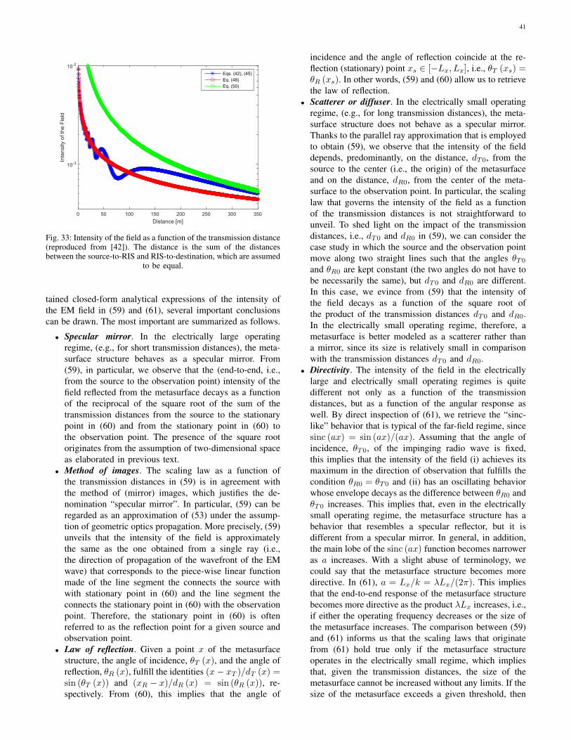
41
0 50 100 150 200 250 300 350Distance [m]
10-3
10-2In
tens
ity o
f the
Fie
ld
Eqs. (42), (45)Eq. (48)Eq. (50)
Fig. 33: Intensity of the field as a function of the transmission distance(reproduced from [42]). The distance is the sum of the distancesbetween the source-to-RIS and RIS-to-destination, which are assumed
to be equal.
tained closed-form analytical expressions of the intensity ofthe EM field in (59) and (61), several important conclusionscan be drawn. The most important are summarized as follows.
• Specular mirror. In the electrically large operatingregime, (e.g., for short transmission distances), the meta-surface structure behaves as a specular mirror. From(59), in particular, we observe that the (end-to-end, i.e.,from the source to the observation point) intensity of thefield reflected from the metasurface decays as a functionof the reciprocal of the square root of the sum of thetransmission distances from the source to the stationarypoint in (60) and from the stationary point in (60) tothe observation point. The presence of the square rootoriginates from the assumption of two-dimensional spaceas elaborated in previous text.
• Method of images. The scaling law as a function ofthe transmission distances in (59) is in agreement withthe method of (mirror) images, which justifies the de-nomination “specular mirror”. In particular, (59) can beregarded as an approximation of (53) under the assump-tion of geometric optics propagation. More precisely, (59)unveils that the intensity of the field is approximatelythe same as the one obtained from a single ray (i.e.,the direction of propagation of the wavefront of the EMwave) that corresponds to the piece-wise linear functionmade of the line segment the connects the source withwith stationary point in (60) and the line segment theconnects the stationary point in (60) with the observationpoint. Therefore, the stationary point in (60) is oftenreferred to as the reflection point for a given source andobservation point.
• Law of reflection. Given a point x of the metasurfacestructure, the angle of incidence, θT (x), and the angle ofreflection, θR (x), fulfill the identities (x− xT )/dT (x) =sin (θT (x)) and (xR − x)/dR (x) = sin (θR (x)), re-spectively. From (60), this implies that the angle of
incidence and the angle of reflection coincide at the re-flection (stationary) point xs ∈ [−Lx, Lx], i.e., θT (xs) =θR (xs). In other words, (59) and (60) allow us to retrievethe law of reflection.
• Scatterer or diffuser. In the electrically small operatingregime, (e.g., for long transmission distances), the meta-surface structure does not behave as a specular mirror.Thanks to the parallel ray approximation that is employedto obtain (59), we observe that the intensity of the fielddepends, predominantly, on the distance, dT0, from thesource to the center (i.e., the origin) of the metasurfaceand on the distance, dR0, from the center of the meta-surface to the observation point. In particular, the scalinglaw that governs the intensity of the field as a functionof the transmission distances is not straightforward tounveil. To shed light on the impact of the transmissiondistances, i.e., dT0 and dR0 in (59), we can consider thecase study in which the source and the observation pointmove along two straight lines such that the angles θT0
and θR0 are kept constant (the two angles do not have tobe necessarily the same), but dT0 and dR0 are different.In this case, we evince from (59) that the intensity ofthe field decays as a function of the square root ofthe product of the transmission distances dT0 and dR0.In the electrically small operating regime, therefore, ametasurface is better modeled as a scatterer rather thana mirror, since its size is relatively small in comparisonwith the transmission distances dT0 and dR0.
• Directivity. The intensity of the field in the electricallylarge and electrically small operating regimes is quitedifferent not only as a function of the transmissiondistances, but as a function of the angular response aswell. By direct inspection of (61), we retrieve the “sinc-like” behavior that is typical of the far-field regime, sincesinc (ax) = sin (ax)/(ax). Assuming that the angle ofincidence, θT0, of the impinging radio wave is fixed,this implies that the intensity of the field (i) achieves itsmaximum in the direction of observation that fulfills thecondition θR0 = θT0 and (ii) has an oscillating behaviorwhose envelope decays as the difference between θR0 andθT0 increases. This implies that, even in the electricallysmall operating regime, the metasurface structure has abehavior that resembles a specular reflector, but it isdifferent from a specular mirror. In general, in addition,the main lobe of the sinc (ax) function becomes narroweras a increases. With a slight abuse of terminology, wecould say that the metasurface structure becomes moredirective. In (61), a = Lx/k = λLx/(2π). This impliesthat the end-to-end response of the metasurface structurebecomes more directive as the product λLx increases, i.e.,if either the operating frequency decreases or the size ofthe metasurface increases. The comparison between (59)and (61) informs us that the scaling laws that originatefrom (61) hold true only if the metasurface structureoperates in the electrically small regime, which impliesthat, given the transmission distances, the size of themetasurface cannot be increased without any limits. If thesize of the metasurface exceeds a given threshold, then
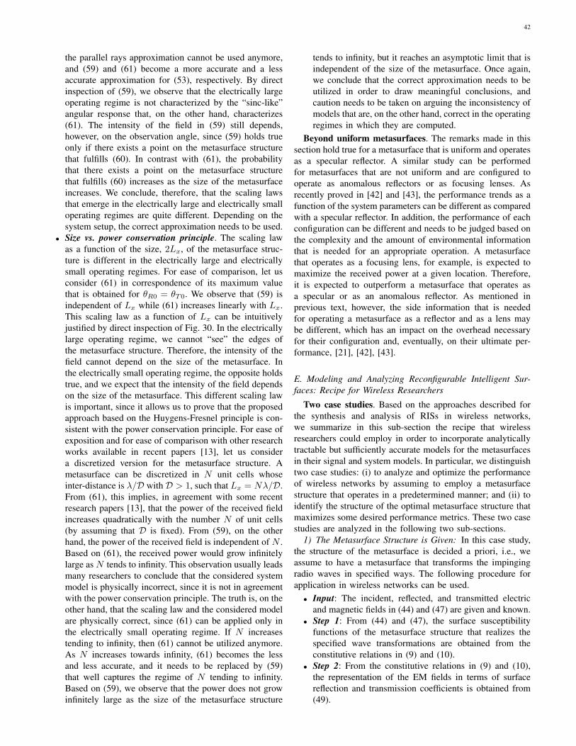
42
the parallel rays approximation cannot be used anymore,and (59) and (61) become a more accurate and a lessaccurate approximation for (53), respectively. By directinspection of (59), we observe that the electrically largeoperating regime is not characterized by the “sinc-like”angular response that, on the other hand, characterizes(61). The intensity of the field in (59) still depends,however, on the observation angle, since (59) holds trueonly if there exists a point on the metasurface structurethat fulfills (60). In contrast with (61), the probabilitythat there exists a point on the metasurface structurethat fulfills (60) increases as the size of the metasurfaceincreases. We conclude, therefore, that the scaling lawsthat emerge in the electrically large and electrically smalloperating regimes are quite different. Depending on thesystem setup, the correct approximation needs to be used.
• Size vs. power conservation principle. The scaling lawas a function of the size, 2Lx, of the metasurface struc-ture is different in the electrically large and electricallysmall operating regimes. For ease of comparison, let usconsider (61) in correspondence of its maximum valuethat is obtained for θR0 = θT0. We observe that (59) isindependent of Lx while (61) increases linearly with Lx.This scaling law as a function of Lx can be intuitivelyjustified by direct inspection of Fig. 30. In the electricallylarge operating regime, we cannot “see” the edges ofthe metasurface structure. Therefore, the intensity of thefield cannot depend on the size of the metasurface. Inthe electrically small operating regime, the opposite holdstrue, and we expect that the intensity of the field dependson the size of the metasurface. This different scaling lawis important, since it allows us to prove that the proposedapproach based on the Huygens-Fresnel principle is con-sistent with the power conservation principle. For ease ofexposition and for ease of comparison with other researchworks available in recent papers [13], let us considera discretized version for the metasurface structure. Ametasurface can be discretized in N unit cells whoseinter-distance is λ/D with D > 1, such that Lx = Nλ/D.From (61), this implies, in agreement with some recentresearch papers [13], that the power of the received fieldincreases quadratically with the number N of unit cells(by assuming that D is fixed). From (59), on the otherhand, the power of the received field is independent of N .Based on (61), the received power would grow infinitelylarge as N tends to infinity. This observation usually leadsmany researchers to conclude that the considered systemmodel is physically incorrect, since it is not in agreementwith the power conservation principle. The truth is, on theother hand, that the scaling law and the considered modelare physically correct, since (61) can be applied only inthe electrically small operating regime. If N increasestending to infinity, then (61) cannot be utilized anymore.As N increases towards infinity, (61) becomes the lessand less accurate, and it needs to be replaced by (59)that well captures the regime of N tending to infinity.Based on (59), we observe that the power does not growinfinitely large as the size of the metasurface structure
tends to infinity, but it reaches an asymptotic limit that isindependent of the size of the metasurface. Once again,we conclude that the correct approximation needs to beutilized in order to draw meaningful conclusions, andcaution needs to be taken on arguing the inconsistency ofmodels that are, on the other hand, correct in the operatingregimes in which they are computed.
Beyond uniform metasurfaces. The remarks made in thissection hold true for a metasurface that is uniform and operatesas a specular reflector. A similar study can be performedfor metasurfaces that are not uniform and are configured tooperate as anomalous reflectors or as focusing lenses. Asrecently proved in [42] and [43], the performance trends as afunction of the system parameters can be different as comparedwith a specular reflector. In addition, the performance of eachconfiguration can be different and needs to be judged based onthe complexity and the amount of environmental informationthat is needed for an appropriate operation. A metasurfacethat operates as a focusing lens, for example, is expected tomaximize the received power at a given location. Therefore,it is expected to outperform a metasurface that operates asa specular or as an anomalous reflector. As mentioned inprevious text, however, the side information that is neededfor operating a metasurface as a reflector and as a lens maybe different, which has an impact on the overhead necessaryfor their configuration and, eventually, on their ultimate per-formance, [21], [42], [43].
E. Modeling and Analyzing Reconfigurable Intelligent Sur-faces: Recipe for Wireless Researchers
Two case studies. Based on the approaches described forthe synthesis and analysis of RISs in wireless networks,we summarize in this sub-section the recipe that wirelessresearchers could employ in order to incorporate analyticallytractable but sufficiently accurate models for the metasurfacesin their signal and system models. In particular, we distinguishtwo case studies: (i) to analyze and optimize the performanceof wireless networks by assuming to employ a metasurfacestructure that operates in a predetermined manner; and (ii) toidentify the structure of the optimal metasurface structure thatmaximizes some desired performance metrics. These two casestudies are analyzed in the following two sub-sections.
1) The Metasurface Structure is Given: In this case study,the structure of the metasurface is decided a priori, i.e., weassume to have a metasurface that transforms the impingingradio waves in specified ways. The following procedure forapplication in wireless networks can be used.• Input: The incident, reflected, and transmitted electric
and magnetic fields in (44) and (47) are given and known.• Step 1: From (44) and (47), the surface susceptibility
functions of the metasurface structure that realizes thespecified wave transformations are obtained from theconstitutive relations in (9) and (10).
• Step 2: From the constitutive relations in (9) and (10),the representation of the EM fields in terms of surfacereflection and transmission coefficients is obtained from(49).

43
• Step 3: From (49), the EM fields in a generic observationpoint of a given volume are obtained from the analyticalformulation of the Huygens-Fresnel principle in (53).
• Output: The performance metric of interest is formulatedas a function of the EM fields, and it is used for systemoptimization.
It is worth mentioning that the surface susceptibility func-tions (in Step 1) may be available without any explicit formu-lation of the incident, reflected, and transmitted electric andmagnetic fields. In this case, the procedure starts at Step 2.Also, it is worth mentioning that the analytical formulation inStep 3 needs to be consistent with the input fields.
2) The Metasurface Structure is Optimized: In this casestudy, the structure of the metasurface is not decided a prioribut needs to be chosen in order to maximize some performancemetrics, e.g., the spectral efficiency and the energy efficiency.The following procedure for application in wireless networkscan be used.• Input: The surface susceptibility functions are the un-
known of the problem.• Step 1: The EM fields are formulated in terms of generic
surface susceptibility functions by using (49).• Step 2: From the generic analytical formulation in (49),
the EM fields at a generic observation point of a givenvolume are obtained from the analytical formulation ofthe Huygens-Fresnel principle in (53).
• Step 3: The performance metric of interest is formulatedin terms of EM fields, and, therefore, as a function ofgeneric surface susceptibility functions.
• Output: The optimal surface susceptibility functions thatmaximize the performance metric of interest are cal-culated, and the corresponding metasurface structure isidentified.
Appropriate models need to be used. We conclude thissection by reminding the readers that, regardless of the specificproblem as hand, it is important that realistic models for themetasurfaces and for the propagation of radio waves are em-ployed. This is necessary in order to obtain results that are inagreement with the fundamental laws of physics. The methodsdescribed in this section, even though are based on someassumptions, may allow one to solve a broad class of researchproblems in wireless networks, and, more importantly, mayhelp one understand the potential benefits and the limitationsof employing RISs for wireless applications.
V. THE STATE OF RESEARCH
In this section, we report a comprehensive summary of theresearch activities on RIS-empowered SREs that are availableto date. The research papers are split into main categories anda brief description for each paper is given.
A. Tutorials and Surveys
During the last two years, several survey and tutorial paperson the application of RISs to the design of wireless networkshave been published [26], [27], [28], [45], [46], [47], [48],[49], [50], [51], [52], [53], [54], [55]. In [47], the concept
of SREs is comprehensively discussed along with a historicalperspective of initial contributions in this field of research.In [48], the applications of RISs as anomalous reflectorsand singe-RF transmitters are elaborated, and the bit errorprobability offered by both implementations is analyzed andcompared. In [49], RISs and relays are compared againsteach other. It is shown that RISs are capable of providinga similar average rate as relays, but without necessitating apower amplifier and provided that they are sufficiently large. In[26], [27], [28], the potential need and applications of machinelearning and AI to SREs are investigated.
B. Collaborative Research Projects
Besides the upsurge of research activities in academia andindustry, several collaborative research projects have beenfunded during the last two years. In particular, the EuropeanCommission has recently funded three major research projectson the application of RISs to future wireless networks. TheVisorSurf project [56] began in January 2017. VisorSurfis aimed to develop a full stack of hardware and softwarecomponents for smart and interconnected planar objects witha programmable electromagnetic behavior. The ARIADNEproject [57] began in November 2019. ARIADNE is aimed todevelop innovative technologies and protocols for providingenhanced connectivity to wireless networks that operate inthe D-band (110-170 GHz), by coating environmental objectswith RISs and turning them into controllable reflectors. ThePathFinder project [58] will begin in May 2021. PathFinderis aimed to build the theoretical and algorithmic foundationof RIS-empowered wireless networks by introducing cross-disciplinary methodologies that capitalize on tools from com-munication theory, physics, and electromagnetism.
C. Physics and Electromagnetism
Research on metamaterials and metasurfaces has a very longhistory and countless research contributions can be found inthe open technical literature. The readers interested in havingbackground information on this wide research topic are invitedto consult the many survey papers, tutorial papers, and booksthat are available in the literature. For example, backgroundinformation on metamaterials can be found in the books[59], [60], [61], [62], [63]. Notably, a historical perspectiveon metamaterials can be found in [61]. The theory andapplications of metasurfaces and surface electromagneticscan be found in the book [5], and in the recent survey papers[64] and [65]. Readers interested in the analytical modeling ofapplied electromagnetics and scattering theory are referred tothe books [66] and [67]. The concept of coding metamaterials,which can be viewed as the foundation of RISs, can be foundin [68]. Examples of realizations of metasurfaces with perfectcontrol of the reflection and transmission of radio waves canbe found in [37], [38], [41], [39]. A recent approach to designmetasurfaces with multiple reconfigurable functions can befound in [69]. A recent short survey paper on the state-of-the-art of reconfigurable metasurfaces can be found in [70].A comprehensive survey paper on reconfigurable reflectarrays

44
and array lenses for dynamic antenna beam control is availablein [71].
Main references of this paper. In the present paper, thefocus of Sections II and IV is on the development of com-putational methods for modeling and analyzing metasurfacesfor application to the optimization of wireless communicationsand networks. The approach reported in Sections II and IV is,in particular, focused on a macroscopic homogenized abstrac-tion modeling based on surface susceptibility functions and thecorresponding surface reflection and transmission coefficients.Readers interested in further information on the fundamentaltheory behind this approach are invited to consult [31], [32],[33] and the first four chapters of the book [5]. Readersinterested in the implementation of metasurfaces with perfectanomalous reflection and transmission capabilities are invitedto consult [37], [38], [41], [39]. In these latter papers, inparticular, the implementation challenges of realizing locallyand globally passive metasurfaces with high power efficiencyare extensively discussed and early references on the topic aregiven.
D. Smart Radio Environments Empowered by ReconfigurableIntelligent Surfaces: Initial Works
Tracing back the history of an emerging research field is nota simple task. Going back to the years 2003-2014, we wereable to find a few early papers in which the concepts of “smartsurfaces” and “smart environments” were advocated.
In [29] and [30] published in 2003 and 2005, respectively,one can read “The GSTCs are expected to have wide ap-plication to the design and analysis of antennas, reflectors,and other devices where controllable scatterers are used toform a “smart” surface”; “This could in principle enable usto realize controllable surfaces, able for instance to switchelectronically between reflecting and transmitting states”; and“We see that if a scatterer can be chosen such that the electricand/or magnetic polarizability is changeable on demand, thena smart or controllable surface would be realized”.
In the tree papers [72], [73], [74] published in 2010 and2012, respectively, one can read “This paper deals with anew approach to the control of the propagation environment inindoor scenarios using intelligent walls. The intelligent wallis a conventional wall situated inside a building, but equippedwith an active frequency selective surface and sensors. Theintelligent wall can be designed as a self-configuring and self-optimizing autonomous part of a collaborative infrastructureworking within a high-capacity mobile radio system. The pa-per shows how such surfaces can be used to adjust the electro-magnetic characteristics of the wall in response to changes intraffic demand, monitored using a network of sensors, therebycontrolling the propagation environment inside the building”and “We have proposed a new method of controlling signalcoverage which can be used inside buildings both for coveragecontrolling and avoiding of interference between transmitters.The method is based on changing of electromagnetic proper-ties of intelligent walls which are conventional walls equippedwith an active frequency selective surface and sensors. Thewalls are part of a collaborative autonomous infrastructure
and they are able to adjust their properties, e.g., on the basisof data obtained by sensing of users or cognitive networksensing. The results show that intelligent walls can be stronginstrument to control signal coverage and subsequently tocontrol available level of service. The controlling of coverageis very useful when mobile users change their position in anindoor scenario, because then intelligent walls provide theefficient way to change propagation environment rapidly”.
In [75] published in 2014, the authors demonstrate thatspatial microwave modulators are capable of shaping, in apassive way, complex microwave fields in complex wirelessenvironments, by using only binary phase state tunable meta-surfaces. These findings are obtained through the design ofa 0.4 m2 spatial microwave modulator that consists of 102controllable EM reflectors and that operates at a workingfrequency of 2.47 GHz. The 102 reflectors are controlledby using two Arduino 54-channel digital controllers. In theabstract of the paper, more specifically, one can read “In thisarticle, we propose to use electronically tunable metasurfacesas spatial microwave modulators. We demonstrate that likespatial light modulators, which have been recently provedto be ideal tools for controlling light propagation throughmultiple scattering media, spatial microwave modulators canefficiently shape in a passive way complex existing microwavefields in reverberating environments with a non-coherent en-ergy feedback. We expect that spatial microwave modulatorswill be interesting tools for fundamental physics and will haveapplications in the field of wireless communications”.
During the last five years (2015-2020), and, in particular,during the last two years, the research contributions on RIS-empowered SREs have increased exponentially. The researchpapers available to date are discussed in the following thematicsub-sections.
E. Path-Loss and Channel ModelingA major research issue for analyzing the ultimate perfor-
mance limits, optimizing the operation, and assessing theadvantages and limitations of RIS-empowered SREs is thedevelopment of simple but sufficiently accurate models for thepower received at a given location in space when a transmitteremits radio waves that illuminate an RIS. This is an open andchallenging research issue to tackle. Recently, however, a fewinitial research works have attempted to shed light on modelingthe path-loss of RISs.
In [13], the authors perform a measurement campaign in ananechoic chamber and show that the power reflected from anRIS follows a scaling law that depends on many parameters,including the size of the RIS, the mutual distances betweenthe transmitter/receiver and the RIS (i.e., near-field vs. far-fieldconditions), and whether the RIS is used for beamforming orbroadcasting applications.
In [76], the authors employ antenna theory to computethe electric field in the near-field and far-field of a finite-size RIS, and prove that an RIS is capable of acting as ananomalous mirror in the near-field of the array. The resultsare obtained numerically and no explicit analytical formulationof the received power as a function of the distance is given.Similar findings are reported in [77].

45
In [78], the authors study, through experimental measure-ments, the power scattered from passive reflectors that operatein the millimeter-wave frequency band. Also, the authorscompare the obtained results against ray tracing simulations.By optimizing the area of the surface that is illuminated,it is shown that a finite-size passive reflector can act as ananomalous mirror.
In [79], the authors study the path-loss of RISs in the far-field regime by leveraging antenna theory. The obtained resultsare in agreement with those reported in [76] and [77] underthe assumption of far-field propagation.
In [42], the authors use the scalar theory of diffraction andthe Huygens-Fresnel principle in order to model the path-lossin both the near-field and far-field of RISs, which are modeledas homogenized sheets of electromagnetic material with neg-ligible thickness. By using the stationary phase method, theauthors unveil the regimes under which the path-loss dependson the sum and the product of the distances between the RISand the transmitter, and the RIS and the receiver. The proposedanalytical approach is shown to be sufficiently general for ap-plication to uniform reflecting surfaces, anomalous reflectors,and focusing reflecting lenses.
F. Surface-Based Modulation and Encoding
One of the emerging and promising applications of RISsis to employ them for modulating and encoding data intotheir individual reconfigurable elements. This application ofRISs can be viewed as an instance of spatial modulationand index modulation [6], [7], [8], [9], [10], [11], [12]. Inparticular, recent research activities on this topic constitutea generalization of the concept of spatial modulation basedon reconfigurable antennas, which was introduced in [10] andwas recently engineered and realize in [80]. The bit errorprobability of spatial modulation based on the reconfigurableantennas is studied in [81], by using radiation patterns obtainedfrom a manufactured reconfigurable antenna. The bit errorprobability of RIS-based spatial modulation is studied in [48].
In [82], the author studies the error probability offered byspace shift keying and spatial modulation schemes that employRISs. The author proposes maximum energy-based suboptimaland exhaustive search-based optimal detectors, and analyzestheir performance with the aid of analytical frameworks andnumerical simulations. The obtained results show that RIS-based spatial modulation is capable of providing high datarates at low error rates. A similar study can be found in [83].
In [84], the authors apply the principle of spatial modulationby modulating information onto the ON/OFF states of thereflecting elements of RISs. In addition, passive beamformingis obtained by adjusting the phase shifts of the activatedreflecting elements. To optimize passive beamforming, theauthors formulate an optimization problem and solve it byusing semidefinite relaxation. To retrieve the information datafrom the transmitter and the RIS, the authors introduce atwo-step detection algorithm based on compressed sensingand matrix factorization. The tradeoff between the passivebeamforming gain and the information rate provided by RISsis investigated.
In [85], the authors propose a reflecting modulation schemefor RIS-based communications, where both the reflectingpatterns and transmit signals carry information. To enhancethe reliability of transmission, the authors devise a discreteoptimization-based joint signal mapping, shaping, and re-flecting design that minimizes the bit error probability fora given transmit signal candidate set and a given reflectingpattern candidate set. Numerical results show that the proposedoptimized schemes outperform existing solutions in terms ofbit error probability.
In [86], the authors propose three different architecturesbased on RISs for beam-index modulation in millimeter wavecommunication, which circumvent the line-of-sight blockageof millimeter wave frequencies. The authors derive the op-timal maximum likelihood detector and a low-complexitycompressed sensing detector for the proposed schemes. Theproposed solutions are evaluated through extensive simulationsand analytical bounds.
In [19], the authors conduct an information-theoretic anal-ysis of RIS-empowered wireless networks. An RIS-aidedcommunication link is considered, in which the transmitter cancontrol the state of an RIS via a finite-rate control link. Theauthors derive information-theoretic limits and demonstratethat the capacity is achieved by a scheme that jointly encodesinformation onto the transmitted signal and onto the RISconfiguration. In addition, a novel signaling strategy based onlayered encoding is proposed, which enables practical suc-cessive cancellation-type decoding at the receiver. Numericalexperiments demonstrate that conventional schemes that fix theconfiguration of RISs in order to maximize the signal-to-noiseratio are strictly suboptimal, since they are outperformed bythe proposed strategies.
G. Channel Estimation
Channel estimation is a fundamental issue to tackle in SREswherein nearly-passive RISs are employed. In contrast to othercommunication systems, e.g., relays, which are equipped withsufficiently powerful signal processing capabilities, nearly-passive RISs are equipped with minimal on-board signalprocessing units that are not intended to be used duringtheir normal operation phase. Therefore, new algorithms andprotocols are necessary in order to perform channel estimation,while keeping the complexity of RISs as low as possible andavoiding on-board signal processing operations as much aspossible.
In [87], the authors investigate channel estimation in RIS-based multiple-input-single-output (MISO) links. The imple-mentation and performance advantages of RIS-based commu-nications over traditional relay-based and MIMO systems arediscussed. A minimum mean square error channel estimationprotocol is developed, and, based on the estimated channels,the phase shifts of the RIS are optimized by employing agradient ascent algorithm.
In [88], the authors introduce optimal methods for estimat-ing the cascaded channel from the transmitter to the receiver,i.e., the combined channel that includes the link from thetransmitter to the RIS and the link from the RIS to the receiver.

46
The proposed method is based on activating the RIS elementsbased on a sequence of patterns, which are selected basedon the minimum variance unbiased estimation principle. Itis found that the channel estimation phase mimics a seriesof discrete Fourier transforms. The authors show that theestimation variance of the proposed algorithms is one orderof magnitude smaller compared with traditional approaches.
In [89], the authors formulate the channel estimation prob-lem in RIS-based systems as a constrained estimation errorminimization problem, which is tackled by using the methodsof Lagrange multipliers and a dual ascent-based algorithm. TheCramer-Rao lower bounds are determined for benchmarkingpurposes. It is shown that the derived method yields betteraccuracy, in the low signal-to-noise ratio regime, comparedwith least square methods.
In [90], the authors develop an algorithm for estimatingthe cascaded channel. The proposed approach leverages com-pressive sensing methods, by leveraging the sparsity availablein the cascaded channel. In addition, the authors extend theapproach to the joint estimation of multiple channels in amulti-user network setup. In order to improve the estima-tion performance, the optimization of the training reflectionsequences is considered.
In [91], the authors tackle the channel estimation problemby means of beam training. The associated quantization erroris characterized and evaluated. As a low-complexity alterna-tive for channel estimation, a hierarchical search codebookdesign is proposed. Based on the proposed channel estimationmethods, the performance of RIS-based wireless networks isstudied.
In [92], the authors propose a three-phase protocol for esti-mating large numbers of channel coefficients, for applicationto RIS-assisted uplink systems, by using a small number ofpilot symbols. Building upon the observation that each RISelement reflects the signals from all the users to the transmittervia the same channel, the authors quantify the time that isnecessary to estimate all required channels. The authors showthat massive MIMO may play an important role in reducingthe channel estimation overhead in RIS-based communicationsystems.
In [93], the authors consider the uplink of a network withmassive connectivity and investigate the joint problem ofchannel estimation and activity detection. The problem isformulated as a sparse matrix factorization, matrix completion,and multiple measurement vector problem, and a three-stagealgorithm is proposed for solving it, by leveraging messagepassing methods.
In [94], the authors propose a low-complexity channel in-formation acquisition method for RIS-assisted communicationsystems that exploit the sparsity of millimeter-wave channelsand the topology of RISs. Compared with state-of-the-artmethods, the proposed approach requires less time-frequencyresources for acquiring the channel information.
In [95], the authors tackle the problem of joint channelestimation and sum-rate maximization in the uplink of asingle-user RIS-based system. In particular, the phase shiftsof RISs are assumed to be discretized. A practical but sub-optimal channel estimation method based on the discrete
Fourier transform and on a truncation of Hadamard matrices isdeveloped. Based on the estimated channel, rate optimizationis tackled by designing the discrete phase shifts at the RIS. Tothis end, a low-complexity successive refinement algorithm isdeveloped. By using numerical simulations, the authors showthat the performance of the proposed method depends on thequality of the initialization point.
In [96], the authors formulate the channel estimation prob-lem of an RIS-assisted multiuser MIMO system as a matrix-calibration based matrix factorization task. This is exploitedin order to reduce the length of the training sequences for es-timating the cascaded channel, which includes the transmitter-to-RIS and the RIS-to-receiver links. By assuming slow-varying channel components and channel sparsity, the authorspropose a message-passing based algorithm that factorizes thecascaded channel. The authors present an analytical frameworkto characterize the theoretical performance of the proposedestimator in the large-system limit.
In [97], the authors propose a method for channel estimationthat is based on the parallel factor decomposition algorithm inorder to unfold the cascaded channel from the transmitter tothe receiver. The proposed method is based on an alternatingleast squares algorithm that iteratively estimates the channelbetween the transmitter and the RIS as well as the channelbetween the RIS and the users. Simulation results show thatthe proposed iterative channel estimation method outperformsbenchmark schemes based on genie-aided information.
In [98], the authors propose a compressed-sensing-basedchannel estimation algorithm in which the angular channelsparsity of large-scale arrays that operate at millimeter wavefrequencies is exploited to perform channel estimation at areduced pilot overhead. The authors design pilot signals basedon prior knowledge of the line-of-sight-dominated transmitter-to-RIS channel as well as prior information on the high-dimensional transmitter-to-receiver and RIS-to-receiver chan-nels, by using compressed sensing methods. A distributedorthogonal matching pursuit algorithm is exploited in orderto capitalize on the channel sparsity.
In [99], the authors develop a joint channel estimationand beamforming design for RIS-assisted MISO systemsin the millimeter-wave frequency band. In order to reducethe training overhead, the inherent sparsity of millimeter-wave channels is exploited. The authors first find a sparserepresentation of the cascaded channel, and then develop acompressed-sensing-based channel estimation method. Also,joint beamforming design is performed based on the estimatedchannel.
In [100], the authors propose a two-stage channel estimationscheme by using iterative re-weighted methods for estimatingthe channel parameters in a sequential optimization loop.Simulation results show that the proposed method providesbetter performance than the two-stage orthogonal matchingpursuit approach, in terms of channel estimation error andspectral efficiency gain.
In [101], the authors introduce a channel estimation protocolfor RIS-assisted energy transfer over MISO Rician fadingchannels. In order to account for the practical limitationsof RISs and energy harvesting users, all computations are

47
carried out at the transmitter. The authors derive near-optimaland closed-form expressions for active beamforming at thetransmitter and for passive beamforming at the RIS.
In [102], the authors propose two novel channel estimationmethods by assuming a structured time-domain pattern ofpilots and RIS phase shifts. The authors show that the receivedsignal follows a parallel factor tensor model that can beexploited to estimate the involved communication channels inclosed-form or iteratively. Numerical results corroborate theeffectiveness of the proposed channel estimation methods andhighlight the existing tradeoffs.
In [103], the authors introduce a channel estimation andtransmission design for low scattering channels that is basedon hybrid beamforming architectures. The authors designtwo different codebooks for efficiently realizing the proposedestimation procedure via a three-tree hierarchical search algo-rithm. The two codebooks are referred to as tree dictionarycodebook and phase shifter deactivation codebook. By usingthe estimation information, the authors compute two closed-form transmission designs that maximize the overall spectralefficiency.
In [104], the authors propose a hierarchical training reflec-tion design for progressively estimating the channels based onan RIS-elements grouping and partition method. Specifically, anew discrete Fourier transform Hadamard-based basis trainingreflection matrix design is proposed in order to minimize themean square channel estimation error. Moreover, the authorspropose two subgroup partition schemes and design efficientsubgroup training reflection matrices to progressively resolvethe subgroup aggregated channels of each group over theblocks. Based on the resolved subgroup aggregated channels,passive beamforming is used for improving the achievablerate, by taking into account the derived channel estimationerror covariance matrix. Also, a low-complexity successiverefinement algorithm with properly designed initializations isproposed in order to obtain high-quality suboptimal solutions.
In [105], the authors introduce a two stage channel esti-mation method. Based on the proposed algorithm, the directchannel between the access point and the users is estimatedduring the first stage. The RIS channels are estimated duringthe second stage by using a bilinear adaptive vector approxi-mate message passing algorithm. A phase shift design for theRIS elements, which approximately maximizes the channelgain at the user, is proposed.
In [106], the authors propose a two-timescale channelestimation framework. The key idea of the framework is toexploit the property that the transmitter-RIS channel is high-dimensional but quasi-static, while the RIS-receiver channelis mobile but low dimensional. To estimate the quasi-statictransmitter-RIS channel, the authors propose a dual-link pilottransmission scheme, in which the transmitter emits downlinkpilots and receives uplink pilots reflected by the RIS. The au-thors propose a coordinate descent-based algorithm to recoverthe transmitter-RIS channel. With the aid of numerical results,the authors show that the proposed two-timescale channelestimation framework can achieve accurate channel estimationwith low pilot overhead.
In [107], the authors study the problem of channel estima-
tion for ambient backscattering. The authors design an estima-tor consisting of an initial estimation step and a subsequentiteration phase in order to acquire the channel parameters. Tofurther evaluate the performance of the designed estimator,the authors derive Cramer-Rao lower bounds for the channelestimates.
In [108], the authors introduce a general framework for theestimation of the transmitter-RIS and RIS-receiver cascadedchannel, by leveraging a combined bilinear spare matrixfactorization and matrix completion. In particular, the authorspresent a two-stage algorithm that includes a generalized bi-linear message passing algorithm for matrix factorization anda Riemannian manifold gradient-based algorithm for matrixcompletion. Simulation results illustrate that the proposedmethod achieves accurate channel estimation performance forapplication to RIS-assisted systems.
In [109], the authors present an architecture for RISs thatcomprises an arbitrary number of passive reflecting elements,a simple controller for their adjustable configuration, and asingle RF chain for baseband measurements. By capitalizingon the proposed architecture and by assuming sparse wirelesschannels in the beamspace domain, the authors introduce analternating optimization approach for the explicit estimationof the channel gains by relaying on a single RF chain. Simu-lation results demonstrate the channel estimation accuracy andachievable performance of the proposed solution as a functionof the number of training symbols and the number of RISreflecting elements.
H. Performance EvaluationSince their inception, RISs have been under study for
unveiling their fundamental performance limits and the impactof the imperfect knowledge of various systems parameters ontheir achievable performance. In this context, several exact,approximate, and asymptotic analytical frameworks have beendeveloped in order to quantify the advantages and limitationsof RISs in different network scenarios.
In [110], the authors study the impact of the finite resolutionof the RIS phase shifts on the achievable performance. Inparticular, the authors introduce an approximated expressionof the achievable data rate of an RIS-aided communicationsystem, and derive the minimum number of phase shifts thatis necessary in order to guarantee a data rate degradationconstraint.
In [111], the authors study the capacity degradation thatstems from potential hardware impairments in RIS-aidedsystems. In the absence of hardware impairments, the first-order derivative of the capacity with respect to the surface-area is shown to be proportional to the inverse of it. Inthe presence of hardware impairments, the latter performancemetric is degraded. The authors introduce a model for thehardware impairments, and derive the effective noise densityand the capacity loss in closed-form. The authors investigatedistributed implementations for RIS-aided wireless systems aswell, and show that the impact of hardware impairments canbe reduced due to the smaller size of each RIS.
In [112], the authors study the asymptotic rate of an RIS-based uplink channel in which an RIS is equipped with a

48
large number of reflecting elements. Also, the authors takechannel estimation errors and spatially correlated multi-userinterference in account. It is shown that channel hardeningeffects occur, similar to massive MIMO systems. Moreover,it is shown that the impairments due to thermal noise, inter-ference, and channel estimation errors become negligible asthe number of RIS reflectors increases. This leads to resultscomparable with those of massive MIMO systems, but at areduced deployment area and costs.
In [113], the authors study the asymptotic optimality of theachievable rate of a downlink RIS-aided system. In order toincrease the achievable system sum-rate, the authors proposea modulation scheme that can be used in an RIS-aided systemwithout interfering with existing users. The authors study theaverage symbol error probability and introduce a resourceallocation algorithm that jointly optimizes the scheduling ofusers and the power control at the transmitter. The proposedasymptotic analysis is validated with the aid of numericalsimulations.
In [114], the authors study the downlink channel of asingle-cell multi-user system in which a base station equippedwith multiple antennas communicates with several single-antenna users through an RIS. The minimum signal-to-interference+noise-ratio (SINR) among the mobile users isasymptotically analyzed, by considering the case studies inwhich the line-of-sight channel matrix between the base stationand the RIS has unit rank and full rank. In the unit rank case,the minimum SINR is shown to be bounded by a quantitythat goes to zero as the number of users increases. In the fullrank case, on the other hand, deterministic approximations arederived and are used to optimize the RIS phase shifts by usingthe gradient ascent method.
In [115], the authors consider a single-user multi-RISs linkcommunication system The RIS phase shifts are adapted tothe line-of-sight components of the propagation channels. Theoutage probability of this system model is derived and it isshown that it decreases as the number of RISs and as thenumber of reflecting elements at each RIS increase. Moreover,the outage probability is characterized in the high signal-to-noise-ratio regime, and it is proved that it decreases with thepower of the line-of-sight links.
In [116], the author introduces a general mathematicalframework for the calculation of the symbol error probabilityof network scenarios in which an RIS is used as a reflectorand as a transmitter. With the aid of numerical simulations,the author compares RIS-based systems with and without theknowledge of channel phases.
In [117], the authors study the distribution of the uplinksum-rate of an RIS-based system. Leveraging the derivedasymptotic expression of the rate, the authors introduce ananalytical framework for computing the outage probability.The authors show that the proposed asymptotic analysis isin close agreement with numerical simulations, under theassumption of a large number of antennas and devices.
In [118], the authors compute the outage probability, theaverage symbol error probability, and the achievable rate ofan RIS-aided system. It is proved that the accuracy of theobtained analytical expressions becomes tighter as the number
of RIS elements grows large. The achievable diversity orderis quantified by deriving single-polynomial approximations inthe high signal-to-noise-ratio regime. The diversity order isshown to be equal to the number of RIS elements.
In [119], the authors study the transmission through anRIS in the presence of phase errors. The authors show thatthe RIS-based composite channel is equivalent to a point-to-point Nakagami fading channel. This equivalent representationallows the authors to perform theoretical analysis of the per-formance and to study the interplay between the performance,the distribution of phase errors, and the number of reflectors.Numerical evaluation of the error probability for a limitednumber of reflectors confirms the theoretical prediction andshows that the performance of RISs is remarkably robustagainst the phase errors.
In [120], the authors present an analytical framework forthe performance evaluation of random rotation-based RIS-aided communications. Under this framework, the authorspropose four low-complexity and energy efficient techniquesbased on two approaches: A coding-based and a selection-based approach. Both approaches depend on random phaserotations and require no channel state information. In particu-lar, the coding-based schemes use time-varying random phaserotations in order to produce a time-varying channel. Theselection-based schemes select a partition of the RIS elementsat each time slot based on the received signal power at thedestination. Analytical expressions for the outage probabilityand energy efficiency of each scheme are derived. The authorsdemonstrate that all schemes can provide significant perfor-mance gains and full diversity order.
In [121], the authors study an RIS-assisted MISO system inwhich a base station equipped with multiple antennas arrangedin a uniform rectangular array serves a single-antenna userwith the help of an RIS equipped with multiple elementsarranged in a uniform rectangular array. The authors considera Rician fading model, where the non-line-of-sight compo-nents vary slowly and the line-of-sight components do notchange. To reduce the overhead for channel estimation andphase adjustment, the authors adopt a fixed maximum-ratiotransmission scheme at the base station, fixed phase shifts atthe RIS, and a constant rate transmission. The authors obtainanalytical expressions of the outage probability and optimizethe RIS phase shifts based on them. Based on the obtainedanalytical framework, the authors analyze the impact of severalkey system parameters on the optimal outage probability.
In [122], the authors revisit the multipath fading phe-nomenon in the context of RISs. In particular, the authorsinvestigate the feasibility of eliminating or mitigating themultipath fading effect, which originates from the movementof mobile receivers, with the aid of RISs. The authors showthat the rapid fluctuations in the received signal strength dueto the Doppler effect can be effectively reduced by using real-time tunable RISs. Also, the authors prove that the multipathfading effect can be eliminated if all available reflectors arecoated with RISs, as well as that the presence of a few RIS-coated reflectors can significantly reduce the Doppler spreadand the deep fades in the received signal.
In [123], the authors study RISs in order to improve the rank

49
of wireless channels. One of the classical bottlenecks of point-to-point MIMO communications is that the capacity gainsprovided by spatial multiplexing are large in the high signal-to-noise-ratio regime. However, the latter regime usually occursin line-of-sight scenarios in which the channel matrix has alow rank, and, therefore, it does not support spatial multiplex-ing. The authors demonstrate that an RIS can be used andoptimized in line-of-sight scenarios in order to increase therank of the channel matrix, which leads to substantial capacitygains.
In [124], the authors study an RIS-aided downlink commu-nication system. The RIS is equipped with B-bit discrete phaseshifters and the base station exploits low-resolution digital-to-analog converters. Without knowledge of the channel stateinformation, the authors propose a practical phase shift designmethod whose computational complexity depends on B, butit is independent of the number of RIS reflecting elements.The authors compute a tight lower bound for the asymptoticrate of the users. As the number of reflecting elements in-creases, the authors prove that the asymptotic rate saturatesbecause the received signal power and the quantization noiseof the digital-to-analog converters increase. Compared withthe optimal continuous phase shift design with perfect channelstate information, the authors prove that the proposed designasymptotically approaches the ideal benchmark performancefor moderate to high values of B.
In [125], the authors analyze the performance of a dis-tributed RIS-aided large-scale antenna system by formulatingan upper bound expression of the ergodic capacity. The authorsprovide an asymptotic optimal phase shift design in orderto maximize the ergodic capacity, and they propose a novelgreedy scheduling scheme that takes the scheduling fairnessinto account. With the aid of simulations, the authors show thatthe analytical upper bounds are sufficiently accurate, and theyvalidate that the proposed scheduling scheme achieves almostthe same ergodic capacity as classical greedy schedulingalgorithms.
In [126], the authors consider three-dimensional RISs thatare deployed as spherical surfaces. Compared with two-dimensional RISs, the authors prove that spherical RISs arecapable of offering wider coverage, simpler positioning tech-niques, and a more flexible deployment.
In [127], the authors investigate the capacity region of amultiple access channel in which two users send independentmessages to an access point that is aided by M reflecting ele-ments. The authors study two practical deployment strategies:A distributed deployment in which the M reflecting elementsform two RISs that are deployed in the vicinity of twousers; and a centralized deployment in which the M reflectingelements are deployed in the vicinity of the access point. Asfor the distributed deployment, the authors derive the capacityregion in closed-form. As for the centralized deployment, theauthors derive a capacity region outer bound and propose anefficient rate-profile based method to characterize an achiev-able rate region. Based on the obtained analytical frameworks,the authors show that the centralized deployment outperformsthe distributed deployment under practical channel setups,and that the capacity gain is higher when the user rates are
asymmetric.In [128], the authors characterize the spatial throughput of
a single-cell multiuser system aided by multiple RISs thatare randomly deployed in the cell. By using analysis andsimulations, the authors prove that an RIS-aided system out-performs full-duplex relaying in terms of spatial throughput,provided that the number of RIS elements exceeds a certainvalue. Moreover, the authors show that different deployingstrategies for RISs and relays should be adopted for theirrespective throughput maximization. Finally, it is shown that,for a given total number of reflecting elements, the systemspatial throughput increases if fewer RISs, each having a largernumber of reflecting elements, are deployed. However, thiscomes at the cost of higher spatially varying user rates.
In [129], the authors consider an RIS that is made of activeelements and that is used as a transmitter. The RIS is modeledas a collection of tiny closely spaced antenna elements. Dueto the proximity of the elements, mutual coupling arises.The authors introduce analytical expressions for the mutualcoupling of two types of planar arrays. The singular values ofthe mutual coupling matrix is shown to approach zero as theantenna element density increases. When the spacing betweenelements becomes small (smaller than half a wavelength), theauthors show that the directivity surpasses the conventionaldirectivity equal to the number of antennas, as well as the gainthat is obtained when modeling the surface as a continuousone. The authors show that the gain is theoretically unboundedas the element density increases for a constant aperture.
In [130], the authors study the feasibility of adoptingRISs for improving the beamforming gain and throughput ofuplink massive MIMO communications. The authors show thatthe favorable propagation property of conventional massiveMIMO systems no longer holds in the presence of RISs.This is because each RIS element reflects the signals fromall the users to the base station via the same channel, thusmaking the channels correlated. As a result, a maximal ratiocombining receive beamforming leads to strong inter-userinterference and low user rates. To tackle this challenge, theauthors propose a novel zero-forcing beamforming strategythat efficiently nulls the interference. By using this approach,the authors show that RIS-assisted massive MIMO systems canachieve a higher throughput compared with their counterpartthat does not use RISs.
I. Stochastic Geometry Based AnalysisRandom spatial processes are considered to be the most
suitable analytical tool to shed light on the ultimate per-formance limits of innovative technologies when applied inwireless networks and to guide the design of optimal algo-rithms and protocols for attaining such ultimate limits. Inparticular, random spatial processes have been successfullyapplied to the analysis of cellular networks, multi-tier cellularnetworks, millimeter-wave cellular networks, multi-antennacellular networks, wireless information and power transfer,energy efficiency optimization, etc. [131], [132], [133], [134],[135], [136], [137], [138], [139]. Despite the many resultsavailable, fundamental issues remain open. In the current liter-ature, in particular, the environmental objects are modeled as

50
entities that can only attenuate the signals, by making the linkseither line-of-sight or non-line-of-sight. Modeling anythingelse is acknowledged to be difficult. Modeling reflections, forexample, either according to the conventional law of reflectionor to the generalized law of reflection, can be considered to bean open and challenging research issue to tackle. Due to theimportance of quantifying the performance gains offered byRISs in large-scale wireless networks, some researchers haverecently attempted to fill this fundamental research gap.
In [140], the authors model the environmental objects with amodified random line process of fixed length and with randomorientations and locations. Based on the proposed modelingapproach, the authors introduce the first analytical frameworkthat provides one with the probability that a randomly dis-tributed object that is coated with an RIS acts as a reflectorfor a given pair of transmitter and receiver. In contrast to theconventional network setup where the environmental objectsare not coated with RISs, the authors prove that the probabilitythat the typical random object acts as a reflector is independentof the length of the object itself.
In [141], the authors consider a MIMO system that isintended to provide wireless services to randomly roamingusers, and they analyze the achievable performance by utilizingstochastic geometry. Each user is assumed to receive thesuperposed signals reflected by multiple RISs. The objective isto serve multiple users by jointly designing the beamformingweights at the RISs and the receiver weights vectors at theusers, respectively. The authors derive closed-form expressionsof the outage probability and the ergodic rate of the users,and their corresponding diversity orders. The analytical resultsdemonstrate that the specific fading environments between theRISs and users have almost no impact on the diversity orderattained.
In [142], the authors use tools from stochastic geometry inorder to study the effect of large-scale deployment of RISson the performance of cellular networks. In particular, theauthors model the blockages using a line Boolean model. Theauthors focus their attention on how equipping a subset ofthe blockages with RISs can enhance the performance of acellular network. The authors derive the ratio of the blind-spots to the total area, and the probability that a typical mobileuser associates with a base station in the presence of an RIS.Also, they derive the probability distribution of the path-lossbetween the typical user and its associated base station. Basedon the proposed analytical framework, the main conclusiondrawn by the authors unveils that the deployment of RISs iscapable of highly improving the coverage regions of cellularbase stations.
J. Optimization and Resource AllocationOptimization of the system radio resources is one of the
most researched topics in the context of RIS-based systems.A significant share of research articles has considered theproblem of passive and active beamforming in MISO systems,i.e., the optimization of the transmit (active) beamforming andthe (passive) RIS phase shifts, by resorting to the populartool of alternating maximization in order to handle the non-convexity of the optimization problem. These papers are
reviewed in the first sub-section. In the second sub-section, wereview the use of other optimization techniques for solving theproblem of active and passive beamforming in MISO systems.Research contributions on other resource allocation problemsare discussed in the third sub-section. In the fourth sub-section,we summarize the notable scenario in which RISs can onlyapply discrete/quantized phase shifts. In the fifth sub-section,we report some recent research directions in the context ofresource optimization for RIS-based networks.
1) Passive / Active Beamforming in MISO Systems byUsing Alternating Optimization
Rate and Energy Efficiency. In [143], [144], the authorsconsider the maximization of the spectral and energy efficiencyin a multi-user MISO downlink network, by alternatively opti-mizing the base station beamforming and the RIS phase shifts.The power allocation problem is optimally solved by a water-filling-like solution, while two methods are developed foroptimizing the RIS phase shifts. The first method employs agradient search approach, while the second method exploits theframework of sequential optimization. Both methods providephase shifts allocations that are stationary points of the spectraland energy efficiency. Moreover, numerical results show thatthe use of RISs significantly improves the energy efficiencycompared to the use of amplify-and-forward relays, while agap is observed with respect to the spectral efficiency. This isdue to the fact that RISs are passive devices, while amplify-and-forward relays are able to apply signal amplification.
In [145], the authors develop a phase shift model that relatesthe RIS phase shifts to the amplitude of the reflection coeffi-cient. A single-user MISO link is considered, and, based on thenew phase shift model, the problem of maximizing the systemachievable rate with respect to the transmit beamforming andto the RIS phase shifts is formulated. In order to cope withthe non-convexity of the problem, alternating optimization isemployed to obtain a low-complexity algorithm, in which thetransmit beamforming and the RIS phase shifts are iterativelyoptimized.
In [146], the authors consider the downlink of an RIS-enabled heterogeneous network, in which a multiple-antennabase station serves single-antenna users. In this context, theauthors develop an algorithm that jointly allocates the basestation transmit power and the RIS phase shifts, in order tomaximize the SINR and the sum-rate at the small cell users,subject to a minimum SINR constraint on the rate of themacro-cell users. An algorithm based on alternating maxi-mization coupled with semi-definite relaxation is developedto tackle the sum-rate maximization problem, by trading offcomplexity and optimality.
In [147], the authors investigate an RIS-aided multi-cellMISO system, with the objective of maximizing the minimumweighted SINR at all users by jointly optimizing the basestation beamforming and the RIS phase shifts, subject toindividual power constraints at the base station. The authorspropose an algorithm to tackle this problem based on thealternating optimization framework, wherein the base stationbeamforming and the RIS phase shifts are alternatively op-timized. The beamforming sub-problem is formulated as a

51
second-order-cone program, while the optimization of the RISphase shifts is tackled by leveraging semi-definite relaxationand successive convex approximation.
In [148], the authors consider the problem of maximizingthe spectral efficiency in RIS-aided MISO systems undernonlinear proportional rate constraints. The problem is tackledby alternatively optimizing the transmit power at the basestation and the reflecting phase shifts at the RIS, whichenables the authors to develop a practical algorithm eventhough no optimality properties can be guaranteed. Numericalsimulations based on the proposed alternating optimizationalgorithm show that RISs are beneficial for improving thenetwork data rate.
In [149], the authors study the downlink of a MIMO multi-cell system, wherein an RIS is deployed at the boundarybetween multiple cells. In this context, the authors tackle theproblem of weighted sum-rate maximization, by alternatingoptimization of the base station beamformer and the RISphase shifts. The beamformer optimization subproblem isobtained in closed form, for fixed RIS phase shifts. Instead,two efficient, but sub-optimal, algorithms are proposed foroptimizing the RIS phase shifts, for fixed beamformers, byleveraging the sequential optimization and the complex circlemanifold methods. Both algorithms yield first-order optimality.
In [150], the authors address the problem of weighted sum-rate maximization in a multi-user RIS-based network. Theproblem is tackled by resorting to alternating optimization,in which the beamforming a the base station is optimizedfor fixed RIS phase shifts, and then the RIS phase shiftsare optimized by keeping fixed the base station beamforming.Lagrangian duality is coupled with fractional programmingmethods for beamforming optimization at the base station,while three closed-form allocations of the RIS phase shiftsare proposed.
In [151], the authors consider a MISO multi-group multicastsystem in which an RIS is used to assist the communication.The authors study the problem of optimizing the base stationprecoding matrix and the RIS reflection coefficients for sum-rate maximization. The resulting optimization problem is firstapproximated by means of a concave lower bound of theobjective function, which is then optimized by alternatingoptimization between the BS precoding and the RIS phaseshifts. Both subproblems are second-order cone programmingproblems, which can be solved by convex optimization theory.Moreover, the use of sequential optimization is utilized inorder to formulate approximate problems that can be solvedin closed-form.
In [152], the authors study an RIS-aided system model andpropose a practical transmission protocol and channel estima-tion algorithm, by assuming an orthogonal frequency divisionmultiplexing (OFDM) transmission scheme and a frequency-selective channel. The problem of maximizing the achievablerate by jointly optimizing the transmit power allocation andthe RIS reflection coefficients is analyzed. The resulting opti-mization problem is non-convex, and the authors propose anefficient algorithm by solving the power allocation problemand the optimization of the phase shifts in an iterative manner.Simulation results show that RISs significantly improve the
performance of OFDM systems.In [153], the authors study an RIS-enhanced wide-band mul-
tiuser OFDM-based MISO system. The transmit beamformerand the RIS phase shifts are optimized, in order to maximizethe average sum-rate over all subcarriers. The problem istackled by exploiting the connection between the sum-ratemaximization and the mean square error minimization, whichis used to equivalently reformulate the problem and to tackleit by using alternating optimization.
In [154], the authors consider an RIS-aided OFDM-basedsystem and tackle the problem of maximizing the systemrate by optimizing the reflection coefficients over differenttime slots within each channel coherence block. The resultingoptimization problem is shown to be non-convex, and it istackled by using alternating optimization with respect to theresource block assignment, the transmit power over eachresource block, and the RIS phase shifts. Numerical resultsshow that RISs are capable of increasing the system rate.
Other performance metrics. In [155], the authors addressthe problem of power control for physical layer broadcastingin the downlink of a multi-user network. In particular, theauthors design the base station transmit beamforming and theRIS phase shifts by using alternating optimization, in orderto minimize the base station power consumption subject to aminimum signal-to-noise ratio constraint for the mobile users.Given the sub-optimality of alternating optimization, a lower-bound of the optimal solution is derived for benchmarkingpurposes. Simulation results show that the proposed methodapproaches the lower bound as the number of RIS reflectingelements increases.
In [156], the authors address the problem of minimizingthe base station power consumption with respect to the basestation beamformer and the RIS phase shifts, subject to mini-mum SINR constraints at the receivers. The resulting problemis tackled by using alternating optimization in order to obtaina practical optimization method, at the price of sacrificingoptimality. A power scaling law for RIS-based links is derived,and it is shown that the received power scales with the squareof the number of RIS reflecting elements.
In [157], the authors consider an RIS-aided multi-userMISO system and investigate the problem of robust beam-forming under the assumption of imperfect knowledge ofthe cascaded channel from the base station to the users.Alternating optimization is adopted to minimize the transmitpower subject to worst-case rate constraints under the assump-tion of a bounded channel error model, and subject to rateoutage probability constraints under a statistical channel stateinformation error model. The results reveal that the numberof RIS elements may have a negative impact on the systemperformance if the cascaded channel is not properly estimated.
In [158], the authors study the symbol error probability of anRIS-aided multiuser MISO downlink network. An expressionof the symbol error probability is derived and alternatingoptimization is used to optimize the symbol-level base stationprecoder and the RIS phase shifts. The resulting algorithm isguaranteed to yield a stationary solution for the non-convexsymbol error probability minimization problem. Simulationresults demonstrate that the use of RISs reduces the bit error

52
probability, especially if a large number of RIS elements isdeployed.
In [159], the authors consider the problem of joint symbol-level precoding and reflection coefficients design in RIS-enhanced multi-user MISO systems. The authors proposeiterative algorithms to solve the power consumption minimiza-tion and quality of service balancing problems. Symbol-levelprecoding and RIS phase shifts are designed by using alternat-ing optimization and the gradient projection and Riemannianconjugate gradient algorithms, in order solve the resultingsub-problems. The results confirm that the employment ofRISs in systems in which symbol-level precoding is used canprovide more efficient multi-user interference exploitation byintelligently manipulating the multi-user channels.
In [160], the authors propose to employ RISs with the aimof improving the performance of over-the-air computation inwireless multi-user networks, thereby achieving ultra-fast dataaggregation. The authors propose an alternating minimizationapproach to optimize the transceiver and the RIS phase shifts.The resulting non-convex quadratically constrained quadraticsub-problem is formulated as a rank-one constrained matrixoptimization problem, which is tackled via the matrix liftingmethod.
In [161], the authors perform the robust design of an RIS-aided multiuser MISO system wherein only imperfect channelstate information is available for optimization purposes. Theconsidered problem consists of minimizing the transmit powerwith respect to the base station beamformer and the RISphase shifts, under the constraint of achievable rate guaranteesfor each user and for all possible channel error realizations.By leveraging some approximations, the considered resourceallocation problem is transformed into a more tractable form,which is then tackled by solving a sequence of semidefiniteprogramming subproblems that can be efficiently solved.
2) Design of Passive / Active Beamforming in MISO Systemsby Using Other Optimization TechniquesIn [162], the authors consider a single-user MISO downlinkwireless communication system, wherein multiple RISs aredeployed to aid the communication. The authors tackle theproblem of optimizing the phase shift matrices of all the RISsby assuming that only statistical channel state informationis available. The resulting optimization problem is solvedby means of the stochastic successive convex approximationmethod. Numerical results show that the proposed algorithmssignificantly outperform the random phase shift scheme, espe-cially when the channel randomness is limited.
In [163], the authors consider a wireless network whereinmultiple RISs are deployed to cooperatively assist the com-munication between a multi-antenna base station and multiplesingle-antenna cell-edge users. The goal is to maximize theweighted sum rate of all cell-edge users by jointly optimizingthe base station transmit beamforming and the RISs phaseshifts. Optimal beamforming at the base station is found byusing the Lagrangian method, while the RIS phase shifts areobtained based on the Rienmann manifold conjugate gradientmethod.
In [164], the authors maximize the spectral efficiency ofan RIS-aided point-to-point MISO system. Transmit beam-
forming and RIS phase shifts are optimized by resortingto iterative methods and manifold optimization techniques.Two suboptimal but low-complexity algorithms are developed.Numerical results reveal that deploying large-scale RISs inwireless systems provides higher spectral and energy efficiencythan increasing the size of the transmit antenna-array at thebase station. This shows how RIS can be effectively used toreduce the number of antennas deployed at the transmitterand receiver, which is an expensive part of a communicationsystem.
In [165], the authors consider a massive MIMO system, inwhich multiple RISs equipped with a large number of reflec-tors are deployed to assist a base station that serves a smallnumber of single-antenna users. The problem of maximizingthe minimum SINR at the users is tackled by jointly optimizingthe transmit precoding vector and the RISs phase shifts. Theproblem is converted into an RIS-user association problem, forwhich an exhaustive search scheme and a greedy-based searchscheme are proposed.
In [166], the authors consider the design of an RIS-assistedsystem in which a multi-antenna base station serves a single-antenna user with the help of an RIS in the presence ofinterference generated by another multi-antenna base stationserving its own single-antenna user. A tractable expressionof the ergodic rate is obtained and it is used as the objectivefunction for optimizing the RIS phase shifts. The optimizationis performed by exploiting the parallel coordinate descentalgorithm, which, in general, converges to a stationary pointof the considered resource allocation problem.
In [167], the authors discuss the problem of using three-dimensional beamforming in RIS-empowered wireless net-works. The authors, in particular, propose a new scheme thatprovides more degrees of freedom in designing and deployingRIS-based networks. The authors consider a base stationequipped with a full dimensional array of antennas, whichoptimizes its radiation pattern in the three dimensional spacein order to maximize the received signal-to-noise-ratio at atarget user. The tilt and azimuth angles of the base station andthe phase shifts at the RIS are jointly optimized. The authorsstudy the impact of the number of reflecting elements at theRIS, by taking into account the effect of the angle of incidenceof signal received by the RIS.
In [168], the authors investigate the problem of passivebeamforming and information transfer in the context of anRIS-aided MIMO system. An RIS is used for enhancing theprimary communication while at the same time transmittinga second data stream by adjusting the state of the reflectingelements. The RIS phase shifts are optimized for sum-capacitymaximization, by formulating the problem as a two-stepstochastic program that is solved by leveraging the stochasticaverage approximation algorithm.
In [169], the authors investigate the design of an RIS-assisted single-user MISO wireless communication system,by jointly optimizing the beamformer at the base stationand the phase shifts at the RIS. The resulting non-convexoptimization problem is tackled by resorting to the branch-and-bound algorithm, which enables the authors to handle thenon-convex unit modulus constraints that need to be enforced

53
on the RIS phase shifts, at the expense of an exponentialcomplexity of the overall optimization algorithm.
3) Design of Other RIS-Based Wireless ScenariosIn [170], the authors consider the problem of joint transmitpower allocation and RIS phase shifts optimization in RIS-aided peer-to-peer communication networks. The objective isto jointly select a sparse passive beamforming matrix andallocate the transmit power such that the minimum SINR ismaximized, subject to a maximum transmit power constraintand to RIS reflection coefficients constraints. The parallelalternating direction method of multipliers is employed totackle the resulting non-convex resource optimization problem.
In [171], the authors introduce the concept of RIS-aidedcell-free network, which is aimed at improving the networkcapacity at a low cost and power consumption. In a widebandscenario, the authors formulate the problem of optimizing thebase station beamforming and the RIS phase shifts, with theaim of maximizing the weighted sum-rate under a transmitpower constraint at the base station and under unit-modulusphase shifts constraints at the RIS. A general joint precodingframework is proposed to solve the resulting problem.
In [172], the authors propose to use RISs for off-shorewireless communications. In particular, the authors assumethat an RIS is placed off-shore to facilitate the communicationbetween single-antenna ships and a multi-antenna coastal basestation. In this context, the article considers the problemof optimizing the system sum-rate with respect to the basestation beamforming, the RIS phase shifts, and the servicetime allocated to each ship. The resulting non-convex prob-lem is tackled by means of alternating optimization, whoseperformance is numerically analyzed to reveal that it yieldscomparable performance to the case in which fully digitalantenna-arrays are used.
In [173], the authors consider a distributed RIS-empoweredcommunication network architecture, in which multiplesource-destination pairs communicate through multiple dis-tributed RISs. In this scenario, the authors study the problemof maximizing the network achievable sum-rate as a functionof the transmit power vector at the sources and the phaseshift matrix at the distributed RISs. The resulting non-convexproblem is tackled by employing alternating optimization, inwhich each sub-problem is cast as a fractional programmingproblem.
In [174], the authors consider an RIS-based cognitive ra-dio communication system, and focus their attention on theproblem of optimizing the sum-rate of the secondary systemas a function of the downlink transmit beamformers at thebase station and the phase shifts at the RIS, and under qualityof serice constraints for the primary system. The resultingoptimization problem is non-convex due to the unit-modulusconstraints imposed to the RIS reflection coefficients. A prac-tical iterative optimization method is developed by using thealternating optimization algorithm with respect to the basestation beamformer and the RIS phase shifts.
In [175], the authors consider a wireless system in whichtwo-way communications take place between a pair of users,with the help of an RIS. Reciprocal and non-reciprocal chan-nels are considered, and the RIS phase shifts are optimized
in order to maximize the SINR at the two receivers. In thereciprocal case, the optimal RIS phase shifts are determined.In the non-reciprocal case, the problem turns out to be moredifficult and is tackled by means of semidefinite relaxation. Inboth cases, the special case of an RIS with a single elementis investigated, and optimal solutions and expressions of thesystem outage probability are calculated.
In [176], the authors consider a device-to-device commu-nication system in which an RIS is employed to enhancethe communication between the device-to-device users whounderlay the cellular users. The authors formulate the problemof sum-rate maximization of the device-to-device users asa function of the transmit powers, the receive linear filters,and the RIS phase shifts. These three blocks of variables areoptimized iteratively by using the alternating maximizationmethod. Closed-form solutions for the transmit powers andreceive filters are provided, while the semi-definite relaxationmethod is exploited for optimizing the RIS phase shifts. Nu-merical results demonstrate that the use of RISs significantlyimproves the system sum-rate.
In [177], the authors consider a wireless system in which amultiple-antenna base station sends a multicast transmissionto single-antenna mobile users, with the help of an RIS.The authors address the problem of maximizing the systemcapacity as a function of the transmit covariance matrix and theRIS phase shifts. Sub-gradient and gradient descent methodsare adopted to tackle the resulting optimization problem. Inaddition, asymptotic analysis is performed in order to derivethe order of growth of the maximum capacity in the regimeof an infinite number of RIS reflecting elements, base stationantennas, and mobile users.
In [178], the authors consider an RIS-aided cognitive radionetwork, wherein multiple RISs are used to improve theachievable rate of secondary users without disturbing the ex-isting primary users in the network. The transmit beamformingvector at the secondary user transmitter and the reflectingcoefficients at each RIS are jointly optimized under a totaltransmit power constraint at the secondary user and under aninterference temperature constraints at the primary user. Theimpact of perfect and imperfect channel state information isanalyzed.
In [179], the authors consider the joint design of the RISphase shifts and the full rank precoder at the transmitterin a point-to-point RIS-assisted MIMO system. The problemof minimizing the error probability is tackled by employingthe alternating maximization method, wherein the two sub-problems are globally solved. In order to develop resourceallocation algorithms with lower complexity, approximate so-lutions for the two sub-problems are derived. Numerical resultsindicate that the lower-complexity methods can still providesatisfactory performance.
In [180], the authors study the maximization of the spectralefficiency in an RIS-assisted MIMO link. The transmit beam-forming and the RIS phase shifts are optimized by convertingthe spectral efficiency maximization problem into the simplerproblem of maximizing the sum of the gains of the differentcommunication paths. This simplified problem is then tackledby resorting to the alternating direction method of multipliers.

54
In [181], the authors address the uplink detection problemin the communication from multiple single-antenna users toan RIS that is connected to a central processing unit thatperforms data detection. The central processing unit acts asa receiver and applies a linear filter to the received signal.The authors determine the system sum-rate and derive analgorithm that yields the equalizer that maximizes the systemsum-rate. Numerical results indicate that the considered RIS-based architecture outperforms traditional approaches basedon matched filtering.
In [182], the authors consider an RIS-aided wireless com-munication system, in which each RIS element has a separatesignal processing unit and is connected to a central processingunit that coordinates the behavior of all RIS elements. Theuser assignments are optimized to maximize the sum-rate andthe minimal user-rate. By constructing a cost matrix basedon the received signal strength at each RIS element for eachuser, a weighted bipartite graph between the users and theRIS elements is obtained. Thanks to the constructed bipartitegraph, the problem of optimal user assignments for sum-ratemaximization is transformed into a linear sum assignmentproblem, and the problem of minimum user-rate maximizationis transformed into a linear bottleneck assignment problem.
4) Discrete Phase Shifts and Phase QuantizationIn [183], the authors address the problem of beamformingoptimization under practical discrete phase shift constraintsat the RIS. The transmit precoder at the access point andthe discrete phase shifts at the RIS are jointly optimizedto minimize the transmit power at the access point whilemeeting the individual SINR targets at the users. Optimalsolutions and suboptimal solutions based on successive convexapproximations are proposed. The authors show that RISs withone bit phase shifters are able to achieve the same asymptoticsquared power gain as continuous phase shifts, but they aresubject to a constant power loss.
In [184], the authors consider a large-scale MIMO system inwhich an that employ discrete phase shifts aids the downlinktransmission. Passive precoding methods are used at the basestation and at the RIS. The objective is to minimize the sumpower of multi-user interference by jointly optimizing theRIS beamforming and the base stations precoding vectors. Atrellis-based joint RIS and base station precoding design isintroduced, according to which the base station precoding ineach cell is performed individually. By applying stochastic op-timization, a low-overhead trellis-based optimization techniqueis introduced, and performance improvements are obtained byminimizing the inter-cell and intra-cell interference. In addi-tion, semi-definite relaxation is applied to develop benchmarkmethods for comparison.
In [185], the authors evaluate the ergodic spectral efficiencyof an RIS-assisted large-scale antenna system. An upper-boundfor the ergodic spectral efficiency is computed and it is utilizedfor optimizing the RIS phase shifts. In particular, the authorsanalyze the case study in which the RIS is capable of applyingonly discrete phase shifts and they evaluate the minimumnumber of quantization bits that are required in order to ensurean acceptable spectral efficiency. Numerical results show thata two bit quantizer is sufficient to ensure an ergodic capacity
degradation of at most one bit/s/Hz.In [186], the authors consider an RIS-aided multi-user
MISO downlink system. The objective is to maximize thesystem sum rate by jointly optimizing the transmit beamformerat the base station and the phase shifts at the RIS. Thecase studies with continuous and discrete RIS phase shiftsare addressed. In order to tackle the resulting optimizationproblem, a smooth approximation of the objective function isderived and a block coordinate accelerated projected gradientalgorithm is developed. Numerical simulations demonstratethat the proposed design achieves satisfactory performance,especially if the RIS is equipped with a large number ofreflecting elements.
In [187], the authors consider an RIS-aided multi-usersystem and design a two-timescale joint active and passivebeamforming optimization approach. The RIS phase shifts areoptimized leveraging the statistical channel state informationof all links, while beamforming at the access point is per-formed based on the instantaneous channel state informationof the effective channels of the users, which account for theoptimized RIS phase shifts. This approach is used to maxi-mize the system weighted sum-rate, under the assumption ofdiscrete phase shift at the RIS. A penalty dual decompositionbased algorithm is developed for the single-user and multi-usercase studies.
In [188], the authors study an RIS-based downlink multi-user multi-antenna system, in which the base station transmitssignals to users via an RIS with limited-resolution phaseshifters. The authors consider the practical case study in whichonly the large-scale fading gain is known at the transceivers.A hybrid beamforming scheme is proposed for sum-rate max-imization, in which digital beamforming is performed at thebase station and analog beamforming is employed at the RIS.The resulting sum-rate maximization problem is tackled byusing alternating optimization.
In [189], the authors address the problem of precoder designin an RIS-based multi-user MISO wireless system, in whichthe RIS phase shifts have a low resolution. The informationto be transmitted is encoded into the configuration of the RISphase shifts and the problem of designing a symbol-level RISprecoder that minimizes the maximum symbol error rate ofsingle-antenna receivers is considered. Under the assumptionthat the symbol-level precoding vector has a one bit resolu-tion, the resulting optimization problem is tackled by usingrelaxation methods coupled with the Riemannian conjugategradient algorithm and the branch-and-bound method.
In [190], the authors consider a single-user system, inwhich an RIS with finite-resolution phase shifters aids thecommunication from a multi-antenna transmitter to a single-antenna receiver. The problem of transmit power minimizationat the transmitter is analyzed, under a minimum signal-to-noiseratio constraint. The problem is tackled by using alternatingmaximization, by taking turn in optimizing the transmit beam-forming and the RIS phase shifts. The authors show that thepower gain at the receiver scales quadratically with the numberof phase shifts of the RIS, but only in the limit of a largenumber of RIS reflecting elements.
In [191], the authors consider a downlink multi-user MISO

55
system, in which an RIS is used to help a base stationcommunicate with the downlink users. Under the assumptionthat the RIS can apply only discrete phase shifts, the sum-ratemaximization problem is addressed by optimizing the digitalbeamforming at the base station and the discrete phase shifts atthe RIS. The resulting resource allocation problem is tackledby an iterative algorithm based on alternating optimization.
In [192], the authors investigate an RIS-assisted multi-user communication system, in which a single-antenna ac-cess point sends independent information to multiple single-antenna users with the aid of an RIS that is capable of applyingdiscrete phase shifts. The authors consider the bi-objectivemaximization of the system ergodic capacity and the delay-limited capacity, and characterize the corresponding Paretoboundary. The authors show that the ergodic capacity canbe achieved by using an alternating transmission strategy inwhich the RIS phase shifts are dynamically changed. In orderto achieve the delay-limited capacity, the authors show that theRIS phase shift matrix needs to be fixed at a specific value.
5) Overhead for Estimation and ControlAll available works on resource optimization for RIS-basednetworks are focused only on the communication phase andassume that channel state information (perfect or imperfect)has been acquired already. This is the conventional approach inthe context of resource allocation in wireless networks. In RIS-based systems, however, channel estimation and feedback af-fect the performance of resource allocation schemes in a morefundamental way than in other instances of wireless networks.For this reason, the design of RIS-based wireless networksrequires, more than in any other wireless systems, the devel-opment of algorithms for joint channel estimation/feedbackand system optimization. A first contribution in this directionhas recently appeared in [21]. Therein, the authors derivean expression of the rate and energy efficiency of a single-user RIS-based MIMO system that explicitly accounts for theoverhead due to channel estimation and feedback. Also, theauthors introduce an optimization framework for the designof the transmit beamforming, the receive filter, the RIS phaseshifts, and the power and bandwidth that are allocated for bothchannel feedback and data transmission phases.
K. Physical Layer SecurityThe premise of physical-layer security is to exploit the
physical properties of wireless channels in order to enhance thecommunication security through appropriate coding and signalprocessing schemes. The analysis of the potential gains andadvantages of RISs for enhancing the physical-layer security ofcommunication links has recently attracted research interestsand attention.
In [193], the authors consider an RIS-aided wiretap chan-nel model, and study the problem of minimizing the powerconsumption under a minimum secrecy rate constraint andby optimizing the transmit power and the RIS phase shifts.The resulting optimization problem is shown to be non-convex, and is tackled by means of semi-definite relaxationand alternating optimization between the transmit powers andthe RIS phase shifts. A closed-form allocation strategy for thetransmit beamformer is derived.
In [194], the authors analyze the problem of secrecy rate op-timization in an RIS-aided wiretap channel, in which a multi-antenna access point communicates with a single-antennareceiver in the presence of a single-antenna eavesdropper. Theauthors assume that exists a strong spatial correlation amongthe channels of the legitimate link and the eavesdroppers. Thetransmit beamforming and the RIS phase shifts are optimizedby resorting to alternating optimization and semidefinite re-laxation methods.
In [195], the authors consider a network scenario in whichan RIS is used to help a base station equipped with a uniformlinear antenna-array that transmits confidential signals to asingle-antenna legitimate user in the presence of a single-antenna eavesdropper. The problem of secrecy rate maximiza-tion is addressed by optimizing the transmit beamformingand the RIS phase shifts. The authors introduce a sub-optimal but low-complexity optimization algorithm by lever-aging quadratic transformations and manifold optimizationtechniques, whose convergence is theoretically proved.
In [196], the authors study the problem of secrecy ratemaximization in an RIS-assisted wiretap channel. The authors,assume a maximum transmit power constraint at the trans-mitter and unit modulus constraints for the RIS phase shifts.The problem is tackled by using alternating optimization,and, in particular, the transmit power control sub-problem issolved in closed-form, and the RIS phase shifts allocation sub-problem is solved in semi-closed form. The convergence of theproposed algorithm is guaranteed theoretically.
In [197], the authors study the problem of secure trans-missions in an RIS-aided wiretap channel while minimizingthe system energy consumption. The authors analyze thecase studies in which the channel between the transmitterand the RIS has unitary and full rank. The optimal transmitbeamforming is obtained by using eigenvalue-based allocation,while the semi-definite relaxation algorithm and the projectedgradient algorithm are used to compute the optimal RIS phaseshifts.
In [198], the authors study an RIS-assisted wiretap channel,in which a multi-antenna transmitter communicates with asingle-antenna receiver in the presence of an eavesdropper.The problem of secrecy rate maximization is considered withrespect to the transmit beamformer and the RIS phase shifts.The resulting optimization problem is tackled by using alter-nating optimization and sequential optimization, which leadsto an efficient but, in general, sub-optimal algorithm.
In [199], the authors analyze a wiretap channel in which anRIS is used to aid a multi-antenna transmitter to communicatewith a single-antenna receiver in the presence of multiplesingle-antenna eavesdroppers. The authors employ artificialnoise for improving the system achievable secrecy rate. Al-ternating optimization is used for optimizing the transmitbeamforming, the artificial noise jammer, and the RIS phaseshifts.
In [200], the authors use artificial noise for ensuring securecommunication in an RIS-assisted network. In particular, amulti-antenna access point exploits an RIS in order to servemultiple single-antenna legitimate users in the presence ofmultiple multi-antenna potential eavesdroppers, whose channel
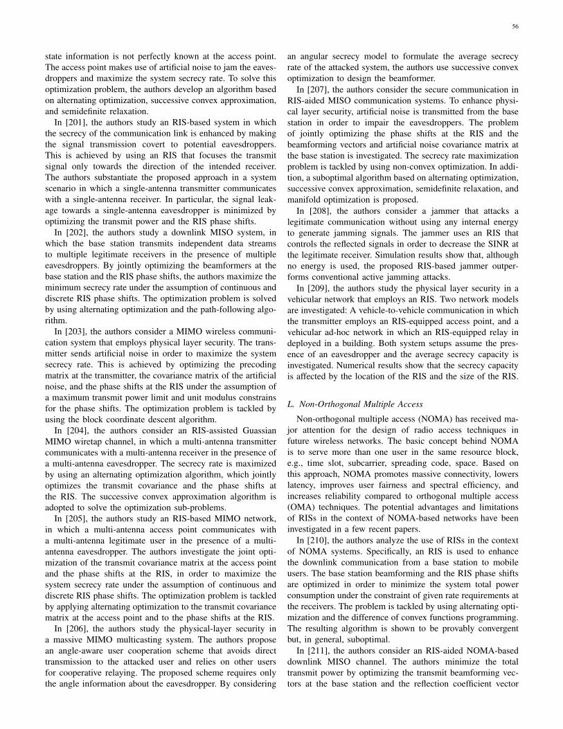
56
state information is not perfectly known at the access point.The access point makes use of artificial noise to jam the eaves-droppers and maximize the system secrecy rate. To solve thisoptimization problem, the authors develop an algorithm basedon alternating optimization, successive convex approximation,and semidefinite relaxation.
In [201], the authors study an RIS-based system in whichthe secrecy of the communication link is enhanced by makingthe signal transmission covert to potential eavesdroppers.This is achieved by using an RIS that focuses the transmitsignal only towards the direction of the intended receiver.The authors substantiate the proposed approach in a systemscenario in which a single-antenna transmitter communicateswith a single-antenna receiver. In particular, the signal leak-age towards a single-antenna eavesdropper is minimized byoptimizing the transmit power and the RIS phase shifts.
In [202], the authors study a downlink MISO system, inwhich the base station transmits independent data streamsto multiple legitimate receivers in the presence of multipleeavesdroppers. By jointly optimizing the beamformers at thebase station and the RIS phase shifts, the authors maximize theminimum secrecy rate under the assumption of continuous anddiscrete RIS phase shifts. The optimization problem is solvedby using alternating optimization and the path-following algo-rithm.
In [203], the authors consider a MIMO wireless communi-cation system that employs physical layer security. The trans-mitter sends artificial noise in order to maximize the systemsecrecy rate. This is achieved by optimizing the precodingmatrix at the transmitter, the covariance matrix of the artificialnoise, and the phase shifts at the RIS under the assumption ofa maximum transmit power limit and unit modulus constrainsfor the phase shifts. The optimization problem is tackled byusing the block coordinate descent algorithm.
In [204], the authors consider an RIS-assisted GuassianMIMO wiretap channel, in which a multi-antenna transmittercommunicates with a multi-antenna receiver in the presence ofa multi-antenna eavesdropper. The secrecy rate is maximizedby using an alternating optimization algorithm, which jointlyoptimizes the transmit covariance and the phase shifts atthe RIS. The successive convex approximation algorithm isadopted to solve the optimization sub-problems.
In [205], the authors study an RIS-based MIMO network,in which a multi-antenna access point communicates witha multi-antenna legitimate user in the presence of a multi-antenna eavesdropper. The authors investigate the joint opti-mization of the transmit covariance matrix at the access pointand the phase shifts at the RIS, in order to maximize thesystem secrecy rate under the assumption of continuous anddiscrete RIS phase shifts. The optimization problem is tackledby applying alternating optimization to the transmit covariancematrix at the access point and to the phase shifts at the RIS.
In [206], the authors study the physical-layer security ina massive MIMO multicasting system. The authors proposean angle-aware user cooperation scheme that avoids directtransmission to the attacked user and relies on other usersfor cooperative relaying. The proposed scheme requires onlythe angle information about the eavesdropper. By considering
an angular secrecy model to formulate the average secrecyrate of the attacked system, the authors use successive convexoptimization to design the beamformer.
In [207], the authors consider the secure communication inRIS-aided MISO communication systems. To enhance physi-cal layer security, artificial noise is transmitted from the basestation in order to impair the eavesdroppers. The problemof jointly optimizing the phase shifts at the RIS and thebeamforming vectors and artificial noise covariance matrix atthe base station is investigated. The secrecy rate maximizationproblem is tackled by using non-convex optimization. In addi-tion, a suboptimal algorithm based on alternating optimization,successive convex approximation, semidefinite relaxation, andmanifold optimization is proposed.
In [208], the authors consider a jammer that attacks alegitimate communication without using any internal energyto generate jamming signals. The jammer uses an RIS thatcontrols the reflected signals in order to decrease the SINR atthe legitimate receiver. Simulation results show that, althoughno energy is used, the proposed RIS-based jammer outper-forms conventional active jamming attacks.
In [209], the authors study the physical layer security in avehicular network that employs an RIS. Two network modelsare investigated: A vehicle-to-vehicle communication in whichthe transmitter employs an RIS-equipped access point, and avehicular ad-hoc network in which an RIS-equipped relay indeployed in a building. Both system setups assume the pres-ence of an eavesdropper and the average secrecy capacity isinvestigated. Numerical results show that the secrecy capacityis affected by the location of the RIS and the size of the RIS.
L. Non-Orthogonal Multiple Access
Non-orthogonal multiple access (NOMA) has received ma-jor attention for the design of radio access techniques infuture wireless networks. The basic concept behind NOMAis to serve more than one user in the same resource block,e.g., time slot, subcarrier, spreading code, space. Based onthis approach, NOMA promotes massive connectivity, lowerslatency, improves user fairness and spectral efficiency, andincreases reliability compared to orthogonal multiple access(OMA) techniques. The potential advantages and limitationsof RISs in the context of NOMA-based networks have beeninvestigated in a few recent papers.
In [210], the authors analyze the use of RISs in the contextof NOMA systems. Specifically, an RIS is used to enhancethe downlink communication from a base station to mobileusers. The base station beamforming and the RIS phase shiftsare optimized in order to minimize the system total powerconsumption under the constraint of given rate requirements atthe receivers. The problem is tackled by using alternating opti-mization and the difference of convex functions programming.The resulting algorithm is shown to be provably convergentbut, in general, suboptimal.
In [211], the authors consider an RIS-aided NOMA-baseddownlink MISO channel. The authors minimize the totaltransmit power by optimizing the transmit beamforming vec-tors at the base station and the reflection coefficient vector

57
at the RIS. This optimization problem is tackled by usingsemidefinite programming, second-order cone programming,and the alternating direction method of multipliers. A low-complexity algorithm based on zero-forcing transmission isproposed.
In [212], the authors analyze the sum-rate optimizationof an RIS-aided NOMA-based downlink MISO channel. Inparticular, the system sum-rate is maximized with respect tothe base station beamformer and the RIS phase shifts. Theproblem is solved by using alternating optimization and byapplying successive convex approximation methods. The casestudy of discrete phase shifts at the RIS is studied and aquantization-based scheme is proposed.
In [213], the authors maximize the minimum rate amongthe users of an RIS-assisted downlink NOMA system. Theoptimization problem is formulated in terms of the transmitbeamforming vector and the RIS phase shifts. A user orderingscheme based on the signal strength of the combined channel isintroduced, in order to decouple the user-ordering design andthe beamforming design. The resulting non-convex problemis tackled by using alternating optimization and semi-definiterelaxation methods. Single-antenna and multi-antenna systemsetups at the base station are analyzed.
In [214], the authors compare the performance betweenNOMA and OMA. The authors optimize the RIS reflectioncoefficients, by assuming a discrete resolution for the phaseshifts, by minimizing the transmit power of the access pointunder the assumption of some specified constraints for theuser rates. It is shown that NOMA may underperform OMAin some network configurations.
In [215], the authors propose an RIS-based NOMA trans-mission scheme in which the number of users that can beserved in each orthogonal spatial direction is larger comparedwith spatial division multiple access schemes. It is shown that,by employing an RIS, the directions of the channel vectors ofthe users can be effectively aligned and that this facilitates theimplementation of NOMA.
In [216], the authors study the performance of two phaseshifting designs, i.e., random phase shifting and coherent phaseshifting, for application to RIS-assisted NOMA systems. Sim-ulation results prove the accuracy of the obtained analyticalresults and are used to compare RIS-NOMA with respect toconventional relaying and RIS-OMA.
In [217], the authors study the downlink transmit powerminimization problem in RIS-empowered NOMA networks,by jointly optimizing the transmit beamformer and the RISphase shifts. The optimization problem is tackled by usingalternating minimization. In particular, the underlaying sub-problems are shown to be non-convex quadratic programs, andthey are tackled by using difference of convex programmingmethods.
In [218], the authors consider a NOMA-based system inwhich a base station transmits a multiplex of signals to multi-ple users by means of an RIS. The performance of the systemmodel is studied by assuming perfect and imperfect successiveinterference cancellation and a one bit coding scheme. Exactand asymptotic expressions of the system outage probabilityand ergodic rate are derived. From the obtained analytical
frameworks, the authors show that RIS-NOMA outperformsRIS-OMA and conventional relaying schemes, and that theperformance of RIS-NOMA improves if the number of re-flecting elements increases.
In [219], the authors study the downlink of an RIS-assistedNOMA system. In order to maximize the system throughput,the authors formulate an optimization problem as a function ofthe channel assignment, the decoding order of NOMA users,the transmit power, and the RIS reflection coefficients. Theresulting optimization problem is non-convex, and a three-step alternating optimization algorithm is proposed to tackleit. In particular, the channel assignment problem is solved byusing a many-to-one matching algorithm, the decoding orderproblem is solved by introducing a low complexity algorithm,and, finally, given the channel assignment and decoding order,the joint power allocation and reflection coefficient design issolved. The three sub-problems are solved iteratively untilconvergence.
In [220], the authors optimize the beamforming vectorsand the RIS phase shifts in an RIS-assisted NOMA system.The authors propose an improved quasi-degradation conditionunder which RIS-NOMA achieves the same performanceas dirty paper coding. The authors characterize the optimalbeamforming of RIS-assisted NOMA and RIS-assisted zero-forcing schemes, by assuming a given RIS phase shift matrix.It is shown that NOMA always outperforms zero-forcing ifthe improved quasi-degradation condition is considered andthe same RIS phase shift matrix is used.
In [221], the authors propose a priority-oriented designfor enhancing the spectral efficiency of an RIS-aided NOMAnetwork. Accurate and approximated closed-form expressionsfor the outage probability and the ergodic rate are derived.Numerical results show that the diversity order of the systemcan be enhanced by increasing the number of phase shifts ofthe RIS.
M. Internet of Things and BackscatteringIn the broadest sense, the Internet of Things (IoT) encom-
passes everything connected to the Internet, but it is often usedto define objects that talk to each other. The IoT is made up ofmassive deployments of devices, encompassing sensors, smartphones, wearables, etc., which are all connected together.One of the major open challenges for the IoT is the limitednetwork lifetime, which is due to the massive deployment ofdevices that are powered by batteries of finite capacities. Inthis context, backscatter communication (or simply backscat-tering), which enables the transmission of information throughthe passive reflection and modulation of an incident radiowave, has emerged as a promising technology for enabling theconnectivity of massive deployments of devices at a low powerconsumption and at a low complexity. In [47], the authorshave elaborated on the potential applications and benefitsof employing RISs for IoT applications. Since then, severalauthors have started researching on the applications of RISsin this context.
In [222], the authors propose an RIS-aided phase shiftbackscatter communication system. The authors study the sce-nario in which the RIS is employed for transmitting secondary

58
information data while relaying primary information data.This is obtained by employing the RIS to relay the primaryinformation data through beamforming and by encoding thesecondary information data onto the phase shifts. The spectralefficiency of the secondary system subject to a minimumspectral efficiency requirement for the primary system isanalyzed, and it is shown that RIS-aided backscattering iscapable of outperforming the system performance.
In [223], the authors propose an RIS-assisted symbioticradio system. The joint design and optimization of the transmitbeamformer and the reflecting phases at the RIS is studied, byminimizing the total transmit power under a rate constraintfor the primary transmission and a signal-to-noise-ratio con-straint for the IoT communication. Alternating optimization isadopted to tackle the resulting optimization problem.
In [224], the authors study an RIS-aided backscatter systemin order to support ultra-reliable communications for IoT ap-plications. By considering random and optimized phase shiftsat the RIS, the authors compute the error probability, by usingthe moment generating function approach. Tight upper boundsare obtained for both independent and correlated channels.Numerical results unveil the impact on the achievable errorperformance of the number of reflecting elements of the RIS.
In [225], the authors analyze and RIS-aided IoT systemover composite fading and shadowing channels. Exact andapproximate expressions for the average capacity, averageerror probability, and outage probability are given. The impactof the transmit power, the fading and shadowing severity, andthe size of the RIS is analyzed.
N. Aerial CommunicationsOver the last years, the use of Unmanned Aerial Vehicles
(UAVs), commonly referred to as drones, has received sig-nificant attention from various industry sectors and researchcommunities. This is mostly attributed to the broad range ofUAV-enabled use cases in, e.g., agriculture, public protection,disaster relief, logistics, media production, mapping, etc. Thetransformation of UAVs into distributed aerial communicationand computing platforms is gathering pace by leveragingresearch advancements in 5G and 6G technologies, edge com-puting, and machine learning. This transformation promisesexciting and high impact use cases and innovations far beyondlegacy UAV solutions. A few recent papers have startedinvestigating the possible applications of RISs in the contextof UAV-based communications.
In [226], the authors study the joint design of the tra-jectory of an UAV and the beamforming design of an RISin order to maximize the average achievable rate. To tacklethe resulting non-convex optimization problem, the authorsdivide the optimization into two sub-problems that consistof optimizing the beamforming at the RIS and the trajectoryof the UAV. The authors derive a closed-form solution forthe beamforming vector for a given trajectory. A sub-optimalsolution for the trajectory is obtained by using successiveconvex approximation methods. Numerical results demonstratethat the use of RISs enhances the average achievable rate.
In [227], the authors consider the deployment of RISs onthe walls of buildings and assume that they can be remotely
configured by cellular base stations in order to coherentlydirect the reflected radio waves towards specific UAVs forincreasing the received signal strength. By using standardizedground-to-air channel models, the authors analyze the signalgain at the UAVs, as a function of the height of the UAVs,and the size, altitude, and distance from base station of theRIS. The authors identify the optimal location (height anddistance from the base stations) of the RIS that maximizesthe performance.
In [228], the authors introduce a three dimensional net-working architecture, enabled by UAVs and RISs, in order toachieve panoramic signal reflections from the sky. The authorsstudy the problem of maximizing the worst-case signal-to-noise ratio in a given coverage area, by jointly optimizingthe transmit beamforming, and the placement and phase shiftsof RIS-mounted UAVs. The resulting problem is non-convexand the optimization variables are coupled. To tackle thisproblem, the authors develop an efficient sub-optimal solutionthat exploits the similarity between optimization of the RISphase shifts and the optimization of the analog beamformingof phased arrays.
In [229], the authors consider a UAV-carried RIS in orderto enhance the performance of millimeter-wave networks. Inparticular, the UAV-carried RIS is used to intelligently reflectsignals from a base station towards a mobile outdoor user,while harvesting energy from the signals so as to powerthe RIS. To maintain a line-of-sight channel, a reinforcementlearning approach is used to model the propagation environ-ment, so that the location and reflection coefficient of theUAV-carried RIS are optimized to maximize the downlinktransmission capacity. Simulation results show the advantagesof using a UAV-carried RIS as compared with a conventionalRIS, in terms of average data rate and achievable downlinkline-of-sight connectivity.
O. Wireless Power Transfer
Wireless power transfer is the transmission of electricalenergy without using wires as a physical link. In a wirelesspower transmission system, a transmitter (driven by electricpower from a power source) generates a time-varying EMfield towards a receiver that extracts power from the fieldand supplies it to an electrical load. The technology ofwireless power transmission can eliminate the use of wiresand batteries, thus increasing the mobility, convenience, andsafety of an electronic device. Wireless power transfer hasreceived major attention from the research community, andseveral authors are currently investigating the potential usesand applications of RISs in this context.
In [230], the authors consider an RIS that assists the trans-mission of a two-user cooperative wireless-powered communi-cation network. The authors study the problem of maximizingthe throughput, by jointly optimizing the phase shifts of theRIS, the transmission time, and the power allocation strategy.Numerical results show that the use of RISs can effectivelyimprove the throughput of cooperative transmissions.
In [231], the authors study a downlink MISO wirelessnetwork with simultaneous wireless and information power
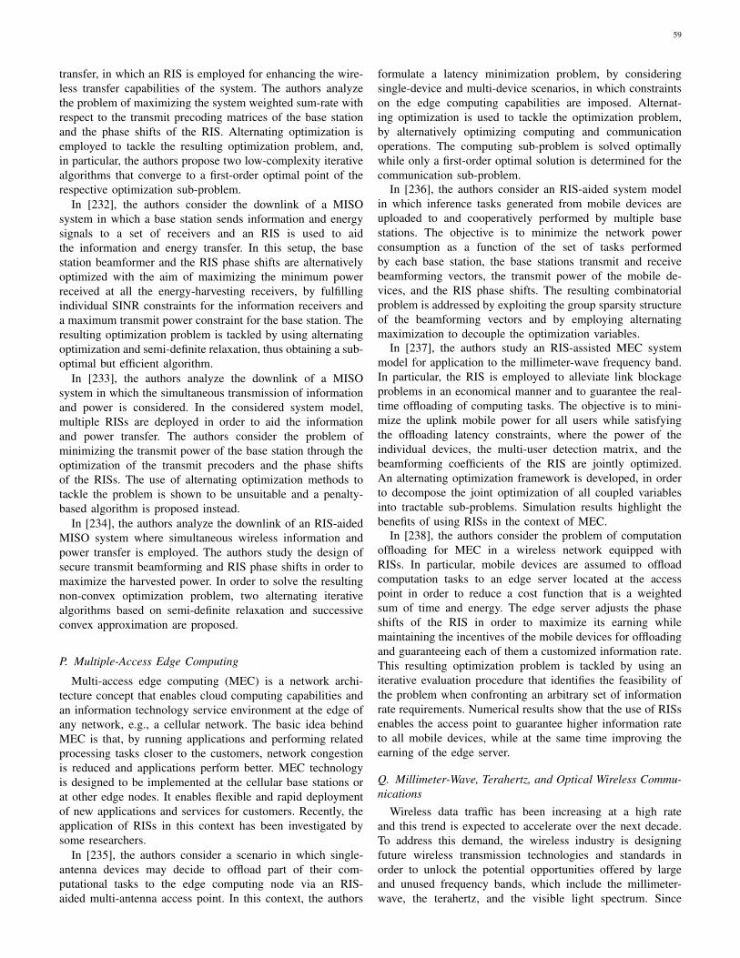
59
transfer, in which an RIS is employed for enhancing the wire-less transfer capabilities of the system. The authors analyzethe problem of maximizing the system weighted sum-rate withrespect to the transmit precoding matrices of the base stationand the phase shifts of the RIS. Alternating optimization isemployed to tackle the resulting optimization problem, and,in particular, the authors propose two low-complexity iterativealgorithms that converge to a first-order optimal point of therespective optimization sub-problem.
In [232], the authors consider the downlink of a MISOsystem in which a base station sends information and energysignals to a set of receivers and an RIS is used to aidthe information and energy transfer. In this setup, the basestation beamformer and the RIS phase shifts are alternativelyoptimized with the aim of maximizing the minimum powerreceived at all the energy-harvesting receivers, by fulfillingindividual SINR constraints for the information receivers anda maximum transmit power constraint for the base station. Theresulting optimization problem is tackled by using alternatingoptimization and semi-definite relaxation, thus obtaining a sub-optimal but efficient algorithm.
In [233], the authors analyze the downlink of a MISOsystem in which the simultaneous transmission of informationand power is considered. In the considered system model,multiple RISs are deployed in order to aid the informationand power transfer. The authors consider the problem ofminimizing the transmit power of the base station through theoptimization of the transmit precoders and the phase shiftsof the RISs. The use of alternating optimization methods totackle the problem is shown to be unsuitable and a penalty-based algorithm is proposed instead.
In [234], the authors analyze the downlink of an RIS-aidedMISO system where simultaneous wireless information andpower transfer is employed. The authors study the design ofsecure transmit beamforming and RIS phase shifts in order tomaximize the harvested power. In order to solve the resultingnon-convex optimization problem, two alternating iterativealgorithms based on semi-definite relaxation and successiveconvex approximation are proposed.
P. Multiple-Access Edge Computing
Multi-access edge computing (MEC) is a network archi-tecture concept that enables cloud computing capabilities andan information technology service environment at the edge ofany network, e.g., a cellular network. The basic idea behindMEC is that, by running applications and performing relatedprocessing tasks closer to the customers, network congestionis reduced and applications perform better. MEC technologyis designed to be implemented at the cellular base stations orat other edge nodes. It enables flexible and rapid deploymentof new applications and services for customers. Recently, theapplication of RISs in this context has been investigated bysome researchers.
In [235], the authors consider a scenario in which single-antenna devices may decide to offload part of their com-putational tasks to the edge computing node via an RIS-aided multi-antenna access point. In this context, the authors
formulate a latency minimization problem, by consideringsingle-device and multi-device scenarios, in which constraintson the edge computing capabilities are imposed. Alternat-ing optimization is used to tackle the optimization problem,by alternatively optimizing computing and communicationoperations. The computing sub-problem is solved optimallywhile only a first-order optimal solution is determined for thecommunication sub-problem.
In [236], the authors consider an RIS-aided system modelin which inference tasks generated from mobile devices areuploaded to and cooperatively performed by multiple basestations. The objective is to minimize the network powerconsumption as a function of the set of tasks performedby each base station, the base stations transmit and receivebeamforming vectors, the transmit power of the mobile de-vices, and the RIS phase shifts. The resulting combinatorialproblem is addressed by exploiting the group sparsity structureof the beamforming vectors and by employing alternatingmaximization to decouple the optimization variables.
In [237], the authors study an RIS-assisted MEC systemmodel for application to the millimeter-wave frequency band.In particular, the RIS is employed to alleviate link blockageproblems in an economical manner and to guarantee the real-time offloading of computing tasks. The objective is to mini-mize the uplink mobile power for all users while satisfyingthe offloading latency constraints, where the power of theindividual devices, the multi-user detection matrix, and thebeamforming coefficients of the RIS are jointly optimized.An alternating optimization framework is developed, in orderto decompose the joint optimization of all coupled variablesinto tractable sub-problems. Simulation results highlight thebenefits of using RISs in the context of MEC.
In [238], the authors consider the problem of computationoffloading for MEC in a wireless network equipped withRISs. In particular, mobile devices are assumed to offloadcomputation tasks to an edge server located at the accesspoint in order to reduce a cost function that is a weightedsum of time and energy. The edge server adjusts the phaseshifts of the RIS in order to maximize its earning whilemaintaining the incentives of the mobile devices for offloadingand guaranteeing each of them a customized information rate.This resulting optimization problem is tackled by using aniterative evaluation procedure that identifies the feasibility ofthe problem when confronting an arbitrary set of informationrate requirements. Numerical results show that the use of RISsenables the access point to guarantee higher information rateto all mobile devices, while at the same time improving theearning of the edge server.
Q. Millimeter-Wave, Terahertz, and Optical Wireless Commu-nications
Wireless data traffic has been increasing at a high rateand this trend is expected to accelerate over the next decade.To address this demand, the wireless industry is designingfuture wireless transmission technologies and standards inorder to unlock the potential opportunities offered by largeand unused frequency bands, which include the millimeter-wave, the terahertz, and the visible light spectrum. Since

60
the wavelengths shrink by order of magnitudes, compared tocurrently used microwave frequencies, at these high frequencybands, diffraction and material penetration will incur greaterattenuation, thus elevating the importance of line-of-sightpropagation, reflection, and scattering. RISs are consideredto be an enabling technology for controlling the radio wavesand for enhancing the connectivity of wireless networks thatoperate at these emerging high frequency bands.
In [239], the authors study the application of RISs in orderto overcome signal path-loss and blind spots in millimeter-wave systems. The problem of maximizing the sum-rate ina multi-user network is addressed by jointly optimizing thetransmit beamforming and the RIS phase shifts. With the aidof alternating maximization, the resulting two optimizationsub-problems are solved in closed-form, and the initial op-timization problem is tackled by iterating between them untilconvergence. The impact of discrete phase shifts is investigatedas well, and a projection method is developed to tackle theassociated optimization problem.
In [240], the authors consider a virtual reality network andstudy the problem of associating RISs to virtual reality usersfor application in the terahertz frequency band. In particular,the authors formulate a risk-based framework based on theentropic value-at-risk and optimize rate and reliability. Theformulated problem accounts for the higher order statisticsof the queue length, thus guaranteeing continuous reliability.Tools such as Lyapunov optimization, deep reinforcementlearning, and recurrent neural network are adopted to tacklethe optimization problem.
In [241], the authors propose geometric meandecomposition-based beamforming for application toRIS-assisted millimeter-wave hybrid MIMO systems.By exploiting the common angular-domain sparsity ofmillimeter-wave channels over different sub-carriers, anorthogonal matching pursuit algorithm is proposed to obtainthe optimal beamforming vector. By leveraging the angleof arrival and angle of departure associated with line-of-sight channels, the authors design the RIS phase shiftsby maximizing the array gain for line-of-sight channels.Simulation results show that the proposed scheme achievesbetter error performance.
In [242], the authors consider an RIS-assisted millimeter-wave communication system in which an RIS is used toovercome the impact of spatial blockages. The objective isto jointly optimize the power of individual devices, the multi-user detection matrix, and the beamforming at the RIS. Tothis end, new methods for minimizing the power under delayrequirements are proposed, and the optimization problem issolved by using alternating optimization. In particular, theconfiguration of the RIS is formulated as a sum-of-inverseminimization fractional programming problem, and it is solvedby using the alternating direction method of multipliers. Theproposed approach is shown to outperform semidefinite relax-ation techniques.
In [243], the authors consider an RIS-aided downlinkwireless system in the millimeter-wave frequency band andformulate a joint power allocation and beamforming designproblem in order to maximize the weighted sum-rate. To solve
the problem, the authors propose a novel alternating manifoldoptimization based beamforming algorithm. Simulation resultsshow that the proposed optimization algorithm outperformsexisting algorithms.
In [244], the authors consider an indoor communicationsystem for application to terahertz communications and studythe application of RISs for improving the reliability of signaltransmission. The authors study the problem of optimizingthe sum-rate performance by selecting the optimal RIS phaseshifts. Two algorithms based on a local search method andcross-entropy method are proposed and their performanceanalyzed with the aid of numerical simulations.
In [245], the authors analyze an RIS-aided millimeter-wavemassive MIMO system and show that a proper positioningof the active antennas with respect to the RIS leads to aconsiderable improvement of the system spectral efficiency.It is revealed that conventional MIMO architectures are eitherenergy inefficient or expensive and bulky if the number oftransmit antennas is large. On the other hand, RIS-aidedMIMO architectures are shown to be highly energy efficientand fully scalable in terms of number of transmit antennas.
In [246], the authors consider the application of RISs inorder to alleviate the line-of-sight requirement in free spaceoptical systems. The authors develop conditional and statisticalchannel models that characterize the impact of the physicalparameters of an RIS, which include the size, position, andorientation, on the quality of the end-to-end channel. Further-more, the authors propose a statistical channel model that ac-counts for the random movements of the RIS, the transmitter,and the receiver. With the aid of the proposed channel models,the authors analyze the advantages and limitations of RISs indifferent scenarios.
In [247], the authors consider the application of RISs forimproving the channel capacity of millimeter-wave indoor net-works. More precisely, the authors propose two optimizationschemes that exploit the customizing capabilities of the RISreflection elements in order to maximize the channel capacity.The first optimization scheme exploits only the adjustabilityof the RIS reflection elements. For this scheme, approximateexpressions of the channel capacity are derived and usedto infer the connection between the channel capacity gainsand the system parameters. The second optimization schemejointly optimizes the RIS reflection elements and the transmitphase precoder. For this scheme, the authors propose a low-complexity technique called global co-phasing to determinethe phase shift values for use at the RIS. Simulation resultsshow that the optimization of the RIS reflection elementsproduces significant channel capacity gains, and that this gainincreases with the number of RIS elements.
In [248], the authors study a millimeter-wave system inwhich a base station that employs hybrid precoding commu-nicates with multiple single-antenna users through an RIS.The mean square error between the received symbols and thetransmitted symbols is minimized by optimizing the hybridprecoder at the base-station and the RIS phase shifts. Theoptimization problem is tackled by resorting to the gradientprojection method. The resulting algorithm is shown to beprovably convergent to a point that fulfills the first-order

61
optimality conditions of the considered optimization problem.In [249], the authors analyze a single-user downlink
millimeter-wave system model in the presence of multipleRISs. The transmit beamforming and the RIS phase shiftsare optimized by analyzing single-RIS and multi-RIS systemsetups. In the single-RIS case, the optimal solution thatmaximizes the signal-to-noise ratio is derived, under theassumption of rank-one channel. In the multi-RIS case, a sub-optimal solution based on the semidefinite relaxation method isproposed. The authors show that RISs provide an effective wayfor signal focusing that is potentially useful for applicationsin the millimeter-wave frequency band. In [250], the authorsgeneralize the study by analyzing the impact of the finiteresolution of the RIS phase shifts.
In [251], the authors investigate the use of RISs for opticalcommunications. In particular, the authors consider a systemmodel in which multiple optical RISs are deployed in theenvironment and are used to build multiple artificial channelsin oder to improve the system performance and to reduce theoutage probability. The authors analyze the impact of threefactors that affect the channel coefficients: beam jitter, jitterof the RISs, and the probability of obstruction. Based on theproposed model, the authors derive the probability densityfunction of the channel coefficients, the asymptotic averagebit error rate, and the outage probability for systems withsingle and multiple RISs. It is revealed that the probabilitydensity function contains an impulse function, which causesirreducible error rate and outage probability floors.
R. Relays and Massive Multiple-Input-Multiple-Output Sys-tems
When new technologies come into the limelight, it is dutifulto critically investigate the potential benefits and limitationsthat they may provide as compared with similar and wellestablished technologies. Therefore, it is sensible to compareRISs with transmission technologies that may be consideredto be closely related to them. In the research literature, twotechnologies are often considered to be the most similar toRISs: Relays and massive MIMO. In general terms, RISs aredifferent with respect to relays and massive MIMO becausethe former emerging technology is intended to be realized ina passive way with minimal power amplification and signalprocessing capabilities, while the latter two technologies relyupon the utilization of individual RF chains and powerfulsignal processing algorithms. The long-term vision of RIS-based SREs consists of realizing a multi-function platform inwhich the transmission, processing, and computation are, asmuch as possible, moved to the EM level. Relays and massiveMIMO, have been envisioned, on the other hand, as platformsin which the EM signal are first converted into the digitaldomain and, after processing, are converted back to the EMdomain. The large-scale experimental platforms reported in[3], [252], [253], [254], which are described in Section V-V,clearly point this out. Despite these general considerations, itis important to identify a fair basis for the comparison of RISsagainst relays and massive MIMO. A few research papers haverecently attempted to shed light on this issue. In [255], notably,
the authors coin the term LIS and describe it as “a new conceptthat conceptually goes beyond contemporary massive MIMOtechnology”.
In [49] and [256], the authors report a comparative studyof RISs against decode and forward relaying. In [49], inparticular, the authors discuss all the advantages and disad-vantages of RISs and relays in a comprehensive manner. Froma performance comparison point of view, both papers lead tosimilar conclusions: RISs may outperform relaying providedthat the size of RISs is sufficiently large. If one considersthe implementation of RISs by using a large number of in-expensive antennas, this implies that several antenna elementsare needed in order to achieve good performance without theneed of using power amplification and signal regeneration.This finding was somehow expected. The interesting findingin [49] is, however, that a sufficiently large RIS that isconfigured to operate as a simple anomalous reflector mayoutperform an ideal full-duplex single-antenna decode andforward relay in terms of achievable data rate. If one considersother performance metrics, such as the energy efficiency andthe power consumption, the gains may be larger if RISs arerealized without using active elements and power amplifiers. Itis important to mention, however, that the signal manipulationsthat can be realized at the EM level are simpler than thosethat can be realized in the digital domain. In addition, theimplementation of metasurface-based RISs with a high powerefficiency requires the design of sophisticated metasurfacestructures, which are the state-of-the-art of research in thefield.
In [23] and [257], the authors report a comparative studyof RISs against MIMO and massive MIMO. The author of[23] analyzes the fundamental aspects of the communicationbetween RISs from the EM standpoint, with a focus onthe degrees of freedom that are offered by the system. Thedeparting point of the author is that the spatial multiplexinggains of MIMO systems, i.e., the channel degrees of freedom,are achieved in rich scattering environments and they areusually lost in favor of beamforming gains in rank-deficientchannels. The main finding of the author is that the degrees offreedom offered by RISs are greater than one in propagationenvironments that are not characterized by rich scattering, e.g.,in line-of-sight channels or for transmission at high frequen-cies (the millimeter-wave frequency range and beyond). Basedon the findings of the author, this is, on the other hand, notpossible in conventional MIMO systems. For this reason, theauthor concludes that RISs may outperform MIMO systemsin those scenarios and may ultimately offer a large increase ofthe spatial capacity density. The authors of [257] move fromthe findings in [258], and analyze the scaling laws of RISsand massive MIMO as a function of the number of reflectingelements. The authors show that the scaling law is quadraticand linear in the number of antenna elements for RISs andmassive MIMO, respectively. RISs are, however, expected toneed a larger number of reflecting elements for achievingsimilar signal-to-noise ratios as massive MIMO, owing to theinherent assumption that RISs can apply only phase shifts andcannot amplify the incident EM fields if they are assumed tobe made of locally or globally passive smart surfaces.

62
S. Software Defined Networking Based Design and Nano-Communication Networks
An important component for realizing the vision of SREs isthe capability of controlling and programming the RISs in asoftware-based fashion [45], [46]. More specifically, the long-term vision consists of realizing fully adaptive metasurfacesthat are flexible enough to synthesize multiple concurrentfunctionalities at the EM level. Researchers of the European-funded project VisorSurf [56] have been researching towardsthe design and implementation of software-defined metama-terials for the last four years. Software-defined metamaterialsare built upon descriptions of EM functionalities in reusablesoftware modules that are specifically designed for changingthe behavior of RISs by sending preset commands. In sim-ple terms, the EM properties of RISs can be reconfiguredat runtime by using a set of software primitives. In orderto disseminate, interpret, and apply the commands, RISsneed, however, the integration of a network of miniaturizedcontrollers within their structure, which are capable of in-teracting locally and communicating globally to realize thedesired EM behavior. The realization of truly software-definedmetamaterials is, therefore, coupled with the realization ofthe network of miniaturized controllers, which are equippedwith communication capabilities that can, e.g., be realized byexploiting nano-communication technologies. Several researchpapers on the design of software-defined metamaterials andnano-communication networks for application to metasurfaceshave recently appeared in the literature. The research issuestacked in these papers encompass the definition of software-defined primitives, the analysis of communication and securityissues, the design of medium access control protocols, routingprotocols, and the network layer configuration and operation[259], [260], [261], [262], [263], [264], [265]. Interestedreaders are referred to [56] for further information.
T. Machine Learning Based Design
The field of machine learning has a long and extremely suc-cessful history. Machine learning has shown its overwhelmingadvantages in many areas, including computer vision, robotics,and natural language processing, where it is normally difficultto find a concrete mathematical model for feature represen-tation. In those areas, machine learning has proved to be apowerful tool as it does not require a comprehensive specifica-tion of the model. Different from the aforementioned machinelearning applications, the development of communicationshas vastly relied on theories and models, from informationtheory to channel modeling. These traditional approaches arecurrently showing some limitations, especially in view of theincreased complexity of communication networks. Therefore,research on machine learning applied to communications, es-pecially to wireless communications, is currently experiencingan incredible surge of interest. Recently, in addition, wirelessresearchers have started researching on the possibility of com-bining together model-based and data-driven approaches, in anattempt of capitalizing on their advantages while overcomingtheir inherent limitations. Machine learning is considered to be
a potential enabler for realizing the vision of RIS-empoweredSREs.
In [27], the authors put forth the connection betweenRISs and machine learning, arguing that both are neededto realize the vision of SREs. The authors discuss how theuse of machine learning is essential to reduce the complexityrelated to the design of RIS-based wireless networks, whichis anticipated to be higher than in conventional wirelessnetworks. To this end, the authors propose a model-aideddeep learning framework, which is further elaborated in [26],that exploits transfer learning to simplify wireless networkdesign by combining together model-based and data-drivenmethods. The same authors discuss the connection betweenRIS-empowered SREs and reinforcement learning in [28].
In [266], the authors introduce a neural-network-basedapproach for configuring the behavior of tiles in RIS-basedenvironments. The wireless propagation is modeled as a cus-tom, interpretable, back-propagating neural network, in whichthe RIS elements act as nodes and their cross-interactionsas links. After a training phase, the neural network learnshow to configure the RISs for improving the communicationperformance. By using a ray tracing simulation environment,the authors show performance gain in agreement with state-of-the-art solutions, but with a distinct gain in reducing thetotal number of active tiles.
In [267], the authors employ an artificial neural network tomaximize the received power in a RIS-based network. Thedownlink of a multi-user MISO system is considered, andthe deep learning framework developed in [27] is applied. Anindoor scenario is considered, and a deep neural network isused as a function approximator to learn the map between thelocations of the users and the corresponding configuration ofthe RIS reflecting elements that maximizes the signal-to-noiseratio at the intended receiver.
In [268], the authors employ deep learning techniques toreduce the design complexity of RIS-based wireless networks.In particular, the authors propose an unsupervised approachto optimize the RIS phase shifts. In the proposed approach, acustomized deep neural network is trained offline by using theobjective function to be optimized for training the parametersof the deep neural network. Simulation results show a gainover conventional approaches based on the use of semi-definite relaxation and alternating optimization, even thoughthe considered approach remains heuristic in the sense that nooptimality property can be claimed.
In [269], the authors propose a joint design of transmitbeamforming and phase shifts in a RIS-assisted MIMO sys-tem, by using a deep reinforcement learning framework. Theproposed deep reinforcement learning algorithm is shown to bescalable for accommodating various system settings. Insteadof utilizing conventional alternating optimization techniques toobtain the transmit beamforming and the RIS phase shifts, theproposed algorithm obtains the joint design simultaneously atthe output of a deep neural network whose training is refinedin real-time.
In [270], the authors propose a deep reinforcement learningframework with reduced training overhead that is able to tunethe phase shifts of the RIS elements with reduced training

63
overhead. The proposed approach paves the way to the deploy-ment of distributed RISs, which are able of self-configurationand operation without the assistance of base stations or in-frastructure nodes. The authors illustrate numerical results thatshow that the proposed online learning framework is able toapproach the same rate as a benchmark system with perfectchannel state information.
In [271], the authors optimize the design of the phaseshifts of an RIS-aided downlink MISO wireless communi-cation system, with the goal of maximizing the receivedsignal-to-noise ratio. Because of the non-convexity of theconsidered resource allocation problem, the authors employdeep reinforcement learning in order to develop a practicalphase shift design algorithm. Numerical results reveal that thedeveloped algorithm can achieve near-optimal signal-to-noiseratio performance with relatively low complexity.
In [272], the authors consider the problem of joint systemdeployment, RIS phase shift control, power allocation, and dy-namic decoding order determination in a RIS-enhanced wire-less system, while enforcing individual data rate requirementsto the multiple users. To tackle this optimization problem,the authors use machine learning. In particular, the authorspropose a novel long short-term memory based echo statenetwork algorithm for predicting the future traffic demandsof multiple users based on an empirical dataset. In addition,the authors propose a decaying double deep Q-network basedposition-acquisition and phase-control algorithm to determinethe position and control policy of the RIS.
In [273], the authors use an artificial neural network forestimating and detecting symbols in an RIS-aided wireless sys-tem. A fully connected artificial neural network is employed toestimate the channels and phase angles from a reflected signalreceived through an RIS. This enables the authors to performsymbol detection without any dedicated pilot signaling, whichsignificantly reduces the overhead required for the operation ofRIS-aided networks. The proposed method is shown to achievea lower bit error rate than traditional detectors.
In [274], the authors investigate the use of deep learning forchannel estimation in a RIS-assisted massive MIMO system.In the proposed scheme, each user has an identical convolu-tional neural network which takes as input the received pilotsignals and yields as output an estimate of the direct channelbetween the transmitter and receiver, and the cascaded channelfrom the transmitter to the receiver through the RIS. Theapproach is extended to a multi-user scenario, wherein eachuser has its own convolutional neural network and estimatesits own channel. With the aid of numerical simulations, theapproach is compared against state-of-the-art deep learningbased techniques and performance gains are shown.
In [275], the authors propose an RIS-based architecturebased on sparse channel sensors. All RIS elements are passiveexcept for a few elements that are active and connected tothe baseband of the RIS controller. The authors propose twosolutions for the design of the RIS reflection matrices basedon compressive sensing and deep learning. The deep learningbased solution has the advantage of requiring a negligibletraining overhead, which makes it practical especially in theRIS context, since it reduces the overhead related to RIS
control.In [276], the authors study an RIS-aided wireless com-
munication system for physical layer security, in which anRIS is deployed to adjust its surface reflecting elements inorder to guarantee the secure communication of multiplelegitimate users in the presence of multiple eavesdroppers.Aiming to improve the system secrecy rate, a design problemfor jointly optimizing the base station beamforming and theRIS reflecting beamforming is formulated, under the assump-tion of different quality of service requirements and time-varying channel condition. As the system is highly dynamicand complex, and it is challenging to address the result-ing non-convex optimization problem, the authors proposea deep reinforcement learning secure beamforming approachthat achieves the optimal beamforming policy. Furthermore,post-decision state and prioritized experience replay schemesare utilized to enhance the learning efficiency and secrecyperformance. Simulation results demonstrate that the proposedsecure beamforming approach can significantly improve thesystem secrecy rate and satisfaction probability.
U. Localization, Positioning, and Sensing
Future wireless networks are expected to offer more thanallowing people, mobile devices, and objects to communicatewith each other. Future wireless networks need to be turnedinto a distributed intelligent communication, sensing, and com-puting platform. Besides connectivity, more specifically, thisenvisioned 6G platform is expected to be capable of sensingthe environment, as well as locally storing and processinginformation, in order to provide network applications andservices with context-awareness capabilities. Such process-ing could accommodate the time critical, ultra-reliable, andenergy-efficient delivery of data, and the accurate localizationof people and devices. Besides enabling enhanced connectiv-ity, therefore, RISs are envisioned to play an important roleto accomplish several other tasks that complement and sup-port communications. Thanks to the possibility of equippingsmart surfaces with energy-harvesting sensors, RISs may beable to offer a dense and capillary network for sensing theenvironment, and for creating environmental maps supportinga variety of emerging applications. Thanks to the possibility ofrealizing large-size smart surfaces, RISs may offer a platformthat provides localization and positioning services with highaccuracy in outdoor and outdoor scenarios, as well as they mayenable near-field highly focusing capabilities for supportingthe communication of massive deployments of devices. Thanksto the possibility of performing algebraic operations andfunctions directly on the impinging radio waves, RISs mayoffer the opportunity to realize a fully EM-based computingplatform unlocking the potential of reconfigurable backscattercommunications. For all these reasons, several researchershave started investigating the potential opportunities offeredby RISs for applications beyond enhanced connectivity.
In [277], the authors envision the use of RISs for positioningpurposes. In particular, the authors analyze the Cramer-Raolower bound for the localization accuracy offered by RISs.Closed-form expressions and accurate approximations for the

64
Cramer-Rao lower bound are derived and are used to prove thatthe localization error offered by RISs decreases quadraticallywith their surface area. This holds true in general exceptfor the case in which a terminal is located exactly on thecentral perpendicular line of the RIS. In this latter case,the localization error decreases linearly. The results showthat a considerable performance improvement is possible overconventional approaches, even when an unknown phase shiftis present in the RIS analog circuit. Moreover, the authorsdiscuss different deployment architectures for RISs that can beused for positioning, and compare the case studies in whichthe deployment area is covered by a single large RIS orby multiple smaller RIS. Results show that none of the twoapproaches always outperforms the other.
In [278], the authors derive the Cramer-Rao lower bound forthe localization accuracy offered by RISs under the assumptionof having discrete phase shifts and measuring amplitudes witha finite resolution. In addition, the authors compute analyt-ical bounds for the Cramer-Rao lower bound related to thepositioning error when the phase information is disregardedand the amplitude is measured with full resolution. Numericalresults are used to analyze and quantify the Cramer-Rao lowerbound loss with respect to the resolution of quantization.
In [279], the authors investigate the use of RISs for posi-tioning and object tracking in millimeter-wave MIMO wirelessnetworks. The authors show that RISs provide promisingperformance thanks to the very sharp beams that they canrealize. In particular, the Cramer-Rao lower bound of thepositioning error is derived, and the impact of the numberof RIS reflecting elements on the localization performance isanalyzed. Numerical results corroborate the theoretical analy-sis, and show that RIS-based positioning systems can achievebetter performance than traditional schemes.
In [280], the authors investigate the design of millimeter-wave MIMO wireless networks with joint communication andlocalization capabilities. This authors show that the use of RISsis beneficial for both tasks, granting both accurate positioningand high data-rate transmission. The authors introduce anadaptive phase shifter design based on hierarchical codebooksand feedback from the mobile station. The proposed schemedoes not require the deployment of active sensors and base-band processing units.
In [281], the authors analyze and discuss the fundamentaltechnical and scientific challenges for the successful use ofRISs for the localization of users and for creating maps of thecoverage area in millimeter-wave wireless networks. In thiscontext, the authors describe their vision on the use of RIS-based localization and illustrate initial results and solutionsalong this line of research. It is argued that the use of RISsfor localization purposes has a great potential for improvingthe localization accuracy, thanks to the sharpness of the beamsthat RISs equipped with a large number of reflecting elementscan realize.
V. Experimental Assessment and Testbeds
From a technological point of view, RISs are a new andemerging paradigm in the context of wireless communications.
Even though reflectarrays have been used for long time inseveral communication-related applications, the realization ofmetasurface-based RISs bring new implementation challenges,and necessitate the realization of proof-of-concept platformsand hardware testbeds in order to substantiate theoreticalfindings and to develop realistic channel and signal modelsfor system design. Even though several research works on thedesign of metasurfaces with advanced functionalities can befound, research on the realization of hardware platforms forapplication to wireless communications is still at its infancy.However, a few relevant research works can be found already.As mentioned in Section II, the MIT’s RFocus [3] and theNTT-DOCOMO [4] platforms are two notable examples ofpromising research activities towards the realization of RISsthat are specifically designed for wireless applications. Theworld’s first field trials performed by NTT DOCOMO andMetaWave in December 2018 on the application of RISs tothe millimeter-wave frequency can be found in [282]. Otherexamples available in the literature are briefly reported asfollows.
In [283] and [284] the authors report the design of a smartreflectarray that is designed for enhancing indoor connectivityin the millimeter-wave frequency band. The reflector panel isfabricated to operate in the 60 GHz frequency band, and itsdimensions are 337 mm, 345 mm, and 0.254 mm for its length,height, and thickness, respectively. The reflector panel is madeof 224 reflector units, whose inter-distance is larger thanone wavelength. Therefore, this design does not fall into thedefinition of metasurfaces. The authors show that the proposedsolution enables the communication of multiple users in thesame indoor area, over the same spectrum band, at the sametime, and without suffering any significant interference, aswell as it enables the reduction of the link outage probability.Recent research results of the same authors are available in[285].
Along the same lines as [3], a few other research groupsaround the world have built prototypes for realizing smartsurfaces that are made of large arrays of inexpensive an-tennas. Notable fully-functional experimental testbeds andexperimental activities along this line of research include thePRESS (programmable radio environment for smart spaces)prototype [252], the LAIA (large array of inexpensive antenna)prototype [253], and the ScatterMIMO prototype [254]. As faras the realization of smart surfaces based on metasurfaces isconcerned, a relevant example is the HyperSurface hardwareplatform: A software-defined, controllable, and programmablemetasurface structure that is capable of shaping the EMwaves in reconfigurable ways. The HyperSurface is underdevelopment by researchers of the European-funded projectVisorSurf [56].
In [286], the authors report a new type of high-gain yetlow-cost RIS made of 256 elements. The proposed RIS com-bines the functions of phase shift and EM radiation on anelectromagnetic surface where PIN diodes are used to realizetwo-bit phase shifts for beamforming. This proposed designforms the basis for the world’s first wireless communicationprototype that realize an RIS having 256 two-bit elements. Theprototype consists of modular hardware and flexible software

65
that encompass the hosts for parameter setting and dataexchange, universal software radio peripherals for basebandand RF signal processing, as well as modules for signaltransmission and reception. Experimental results confirm thefeasibility and efficiency of RISs for wireless communications.In particular, at 2.3 GHz the proposed RIS can achieve a 21.7dBi antenna gain. At the millimeter wave frequency of 28.5GHz, it attains a 19.1 dBi antenna gain. Furthermore, it isshown that the developed prototype is capable of significantlyreducing the power consumption.
In [287], the authors design an RF sensing system forposture recognition based on RISs. The proposed systemcan actively customize the environment in order to providethe desirable propagation properties and diverse transmissionchannels. The prototype has a size of 69 cm × 69 cm ×0.52 cm, and it is composed of a two-dimensional array ofelectrically controllable unit elements. Each row/column ofthe array contains 48 unit elements, which corresponds to asurface made of 2,304 unit elements. Each unit element has asize of 1.5 cm × 1.5 cm × 0.52 cm, and it is composed of fourrectangle copper patches printed on a dielectric substrate. Anytwo adjacent copper patches are connected by a PIN diode thatis controlled by applying appropriate voltages. By combingsimulation and experimental results, the authors show that theposture recognition accuracy increases with the size of the RISand with the number of independently controllable elements.
In [14], [15], [16], [17], [18], the authors report the designand some experimental results on multiple prototypes of recon-figurable metasurfaces that implement single-RF transmitters.In particular, the prototype reported in [15] is designed tohave a full 360 degrees phase response and a reflectivity ofabout 85% at a working frequency of 4.25 GHz. The fabricatedmetasurface sample is made of 8×32 unit cells. The size of aunit cell is 12 mm × 12 mm × 5 mm, which approximatelycorresponds to 0.17λ × 0.17λ × 0.07λ at 4.25 GHz. Thecapacitance of the unit cell is dominated by a varactor diode,which indicates that the phase response of the metasurfacecan be tuned through the bias voltage of the varactor diode.This bias voltage has an approximate linear relationship withthe phase of the reflected wave and can achieve 360 degreesphase modulation. For example, the authors prove that thedesigned metasurface prototype is capable of mimicking thephase response of an eight phase shift keying modulationscheme.
In [13], the authors report the world’s first experimentalmeasurements to characterize the path-loss experienced by EMwaves in the presence of metasurfaces. The authors reportexperiments, which are conducted in an anechoic chamber,for three samples of manufactured metasurfaces with 10,200,1,700, and 256 unit cells, and whose size is 1.02 m × 1 mat 10.5 GHz, 0.34 m × 0.5 m at 10.5 GHz, and 0.384 m ×0.096 m at 4.25 GHz, respectively. The authors prove that thepath-loss as a function of the transmission distance depends onseveral parameters, which include the size of the metasurface,the function applied by the metasurface, and whether thesystem operates in the radiative near-field or in the far-field.
VI. THE ROAD AHEAD
Major research problems to tackle. In this section, weelaborate on some major open research problems that weconsider to be of great importance for unveiling the potentialbenefits and for assessing the advantages and limitations ofRISs against other mature wireless technologies. The listof open research problems is, however, not intended to beexhaustive in light of the steady growth of fundamental andapplied research on RIS-empowered SREs.
EM-based circuital models. The homogenized and macro-scopic model-based approach (either based on surface suscep-tibility functions or surface impedances) briefly summarizedin the present paper is a powerful method for analyzingand optimizing RISs. It constitutes, in particular, a suitableinterface between the physics phenomena underlying the op-eration of RISs and the level of abstraction that is needed forobtaining adequately accurate but sufficiently tractable modelsfor application to wireless communications. This approachhides, however, some aspects related to the practical realiza-tion of RISs, which may be convenient to preserve in theanalytical formulation. For analyzing and optimizing wirelessnetworks, in particular, it may be appropriate to start fromsimple models for the unit cell of metasurfaces, e.g., simpledipoles, and to obtain equivalent EM-based circuital modelsfor metasurface structures, which explicitly account for themutual coupling among the unit cells as a function of theirsize, inter-distance, and spatial arrangements. This will allowus to better understand the potential benefits and limitations ofsub-wavelength metasurface structures, and to better quantifythe potential gains for wireless applications.
Path-loss and channel modeling. In order to evaluate theperformance limits of RISs in wireless networks, we needrealistic models for the propagation of the signals scatteredby metasurfaces. In addition, it is necessary to abandon thecomfortable assumption of far-field propagation, since severalpromising applications and potential advantages of RISs mayemerge in the radiative near-field regime. To this end, it isnecessary to relay upon physics-based models for the propaga-tion of EM fields in proximity of metasurfaces and to accountfor their circuital models in the problem formulation. Besidesthe development of accurate path-loss models for link budgetanalysis, it is necessary to develop fading models for sub-wavelength structures, both at the microscopic level, whichaccount for individual unit cells, and at the macroscopic level,which may be more easily integrated into communication-theoretic frameworks.
Fundamental performance limits. RISs can be employedfor different purposes, which include beamsteering, beamform-ing, focusing, modulation, and joint modulation and encodingwith the transmitter. Depending on the specific application andwave transformation applied, the ultimate performance limitsare not known yet. Recent results have pointed out, in a simplepoint-to-point communication setup, that the channel capacityis achieved by performing joint encoding at the transmitterand RIS, whereas typical criteria that rely on maximizingthe power of the received signal are sub-optimal. Thesefindings are obtained, however, by considering simple models

66
Fig. 34: Electromagnetic-based routing in smart radio environments(reproduced from [47]).
for the metasurface structure, which are in agreement withconventional assumptions in communication and informationtheory. The ultimate performance limits of RISs, how to bestconfigure RISs to achieve them, and the actual gains withrespect to other well established technologies are not knownyet.
Robust optimization and resource allocation. The simpleexamples reported in the present paper confirm that physics-based models for simple metasurfaces, e.g., perfect anomalousreflectors, are more complex that the typical models that com-munication theorists employ in formulating resource allocationproblems. As an example, the amplitude and phase responsesof a metasurface operating as a perfect anomalous reflector arenot independent of each other, and the resulting metasurfacestructure is locally non-passive. It is necessary to integratephysics-based models for metasurface structures into resourceallocation problems, and, in particular, to explicitly accountfor the impact of the sub-wavelength structure of RISs andthe associated design constraints and shaping capabilities ofthe radio waves.
Constrained system design and optimization. One of thepotential novelties of RISs is the possibility of manipulatingthe radio waves impinging upon them without the need of rely-ing on on-board power amplifiers and signal processing units.Some advantages of these assumptions lie in the opportunityof reducing the EM field exposure of human beings and inmaking the metasurfaces easier to recycle. These assumptionsintroduce, however, constraints on the operation of RISswhen they are deployed in wireless networks. Usually, therestrictions on performing signal processing operations on themetasurfaces have an impact on the overhead that is associatedwith gathering the necessary environmental information foroptimizing and configuring RISs. The fundamental trade-offbetween the complexity and power consumption of RISs,as well as the associated overhead needs to be carefullyinvestigated and assessed.
EM-based communications: “Layer-0” networking. RISsmay open the possibility of designing wireless networks inwhich the entire protocol stack for communication is realizedthrough an appropriate shaping and manipulation of the radiowaves at the EM level. This does not encompass only physicallayer functionalities, which have been the main focus ofresearch to date, but the medium access control layer andthe routing layer as well. In scenarios with a high density
of mobile terminals and devices, for example, RISs may beemployed to create a large number of orthogonal wirelesschannels that may be employed for achieving high spatialcapacities through EM-based medium access control protocolswith reduced overhead and contention time, as well as forenabling spatial multiplexing gains in rank-deficient wirelessenvironments. RIS-empowered SREs, in addition, may beviewed as an opportunity to realize EM-based routing pro-tocols (see, e.g., Fig. 34), according to which the radio wavesare routed from the transmitter to the receiver via controlledreflections and refractions at low latencies, low transmissiondelays/jitters, and high reliability, since all operations arerealized directly at the EM level. Research on the potentialuses, advantages, and limitations of capitalizing on RISs forthe design of communication protocols beyond the physicallayer is almost unexplored to date but deserves major attentionand research efforts.
Large-scale networks: Deployment, analysis, and opti-mization. RIS-empowered SREs have several potential appli-cations, which encompass indoor and outdoor environments.The vast majority of research activities conducted so farhave considered the analysis of optimization of “small-size”networks, usually networks that are made of a single RIS. Thisis the natural starting point for assessing the potential benefitsof new technologies. In addition, the analysis of these simplescenarios is based on modeling assumptions that may notnecessarily be sufficiency realistic for the assessment of sub-wavelength metasurfaces. It instrumental to quantify, however,the performance limits of SREs in large-scale deployments.For example, a relevant question may be to identify the densityof RISs to be deployed for increasing the coverage probabilityor the energy efficiency in a large industrial factory or even inthe downtown of a city. This is an almost unexplored researchproblem to be tackled.
Ray tracing and system-level simulators. The deploymentphase of new technologies is usually preceded by extensivesystem-level simulation studies and field test trials. In thiscontext, the use of ray tracing and system-level simulatorsplays a crucial role for overcoming the limitations of simplifiedanalytical studies, and for taking into account realistic spatialtopologies, e.g., three-dimensional maps for territories, cities,streets, buildings, and floor plants of apartments, offices, etc.Current tools that are employed to this end are not suitablefor application to RIS-empowered SREs because the wavetransformations and the scattering models of metasurfacesare not integrated into them. In simple terms, the so-calledgeneralized laws of reflection and refraction that can beviewed as approximations of the response of metasurfacesto impinging radio waves according to the assumptions ofgeometric optics are not available in commercial ray tracingtools and system-level simulators.
Beyond far-field communications. Most research worksconducted in the recent present on RIS-empowered SREs relyupon far-field assumptions. RISs, however, may be made ofgeometrically large surfaces of the order of a few squaremeters. This implies that RISs may operate in the near-field regime in relevant application scenarios, e.g., in indoorenvironments. The use of geometrically large RISs opens the

67
Fig. 35: Towards 3G metasurfaces (slide: Prof. Stefano Maci [288]).
possibility of building new wireless networks that operatein the near-field regime, which is not a conventional designassumption in wireless communications. Research on the fun-damental performance limits, design constraints, and potentialapplications and benefits of near-field communications in RIS-empowered SREs has not received significant attention so far.In light of the potential applications that may be unlocked, e.g.,highly focusing capabilities, the near-field regime is worthedof further attention from the research community.
Beyond communications. Most research works conductedin the recent present on RIS-empowered SREs are focused onapplications that are related to communications. RISs, how-ever, offer opportunity for research that go beyond communi-cations. For example, the high focusing capability of electri-cally large RISs offers the opportunity of using them for high-precision radio localization and mapping (i.e., the constructionof a model or map of the environment). The capabilities ofRISs for these applications and the expected performance as afunction of their size, sub-wavelength structure, and near-fieldvs. far-field operation constitute an open research problem. Inaddition, radio localization and mapping can be considered tobe important enablers for realizing important communication-related tasks.
Advantages and limitations. This can be considered to bethe ultimate goal of conducting research on RIS-empoweredSREs: “Do RISs bring any (substantial) gains as com-pared with other well-established technologies in wirelessnetworks?” At the time of writing, there is no precise answerto this question, and it will probably take a few years of multi-disciplinary research to uncover the tip of the iceberg.
6G wireless vs. 3G metasurfaces. Finally, we concludethis section by emphasizing that the potential benefits of RIS-empowered SREs are conditioned upon the availability ofreconfigurable multi-function metasurfaces with exceptionalcapabilities of manipulating EM waves. Research and devel-opment on this enabling technological field of SEM has justbegan, as illustrated in Fig. 35.
VII. CONCLUSION
For more than seven decades, communication andinformation theorists have built their theories and algorithmsupon C. E. Shannon’s seminal work reported in themonograph “A (The) Mathematical Theory of Communication”(1948). The present article constitutes a first preliminary
attempt that elaborates on the need of reconciling andreuniting Shannon’s mathematical theory of communicationwith G. Green’s landmark essay in the field of mathematicalphysics “An Essay on the Application of MathematicalAnalysis to the Theories of Electricity and Magnetism”(1828) and J. C. Maxwell’s fundamental treatise on thetheory of electromagnetism “A Dynamical Theory of theElectromagnetic Field” (1865).
We conclude the present article by quoting the last para-graph of the preface of G. Green’s essay: “Should the presentEssay tend in any way to facilitate the application of analysisto one of the most interesting of the physical sciences, theauthor will deem himself amply repaid for any labour he mayhave bestowed upon it; and it is hoped the difficulty of thesubject will incline mathematicians to read this work withindulgence, more particularly when they are informed that itwas written by a young man, who has been obliged to obtainthe little knowledge he possesses, at such intervals and by suchmeans, as other indispensable avocations which offer but fewopportunities of mental improvement, afforded”.
REFERENCES
[1] Radiocommunication Sector of ITU, “IMT traffic estimates for theyears 2020 to 2030,” Report ITU-R M. 2370-0, pp. 1–15, Jul. 2015.
[2] K. B. Letaief, W. Chen, Y. Shi, J. Zhang, and Y. Zhang, “The roadmapto 6G: AI empowered wireless networks,” IEEE Commun. Mag.,vol. 57, no. 8, pp. 84–90, Aug. 2019.
[3] V. Arun and H. Balakrishnan, “RFocus: Beamforming using thousandsof passive antennas,” in USENIX Symposium on Networked SystemsDesign and Implementation, Feb. 2020, pp. 1047–1061.
[4] NTT DOCOMO, “DOCOMO conducts world’s first successfultrial of transparent dynamic metasurface,” Jan. 2020. [Online].Available: https://www.nttdocomo.co.jp/english/info/media center/pr/2020/0117 00.html.
[5] F. Yang and Y. Rahmat-Samii, Surface Electromagnetics: With Appli-cations in Antenna, Microwave, and Optical Engineering. CambridgeUniversity Press, Jun. 2019.
[6] M. Di Renzo, H. Haas, and P. M. Grant, “Spatial modulation formultiple-antenna wireless systems: A survey,” IEEE Commun. Mag.,vol. 49, no. 12, pp. 182–191, Dec. 2011.
[7] M. Di Renzo, H. Haas, A. Ghrayeb, S. Sugiura, and L. Hanzo,“Spatial modulation for generalized MIMO: Challenges, opportunities,and implementation,” Proc. of the IEEE, vol. 102, no. 1, pp. 56–103,Jan. 2014.
[8] P. Yang, M. Di Renzo, Y. Xiao, S. Li, and L. Hanzo, “Design guidelinesfor spatial modulation,” IEEE Commun. Surveys Tuts., vol. 17, no. 1,pp. 6–26, First quarter 2015.
[9] P. Yang, Y. Xiao, Y. L. Guan, K. Hari, A. Chockalingam, S. Sug-iura, H. Haas, M. Di Renzo, C. Masouros, Z. Liu, L. Xiao, S. Li,and L. Hanzo, “Single-carrier SM-MIMO: A promising design forbroadband large-scale antenna systems,” IEEE Commun. Surveys Tuts.,vol. 18, no. 3, pp. 1687–1716, Third quarter 2016.
[10] M. Di Renzo, “Spatial modulation based on reconfigurable antennas- A new air interface for the IoT,” in IEEE Military Commun. Conf.,Oct. 2017, pp. 495–500.
[11] E. Basar, M. Wen, R. Mesleh, M. Di Renzo, Y. Xiao, and H. Haas,“Index modulation techniques for next-generation wireless networks,”IEEE Access, vol. 5, pp. 16 693–16 746, Aug. 2017.
[12] M. Wen, B. Zheng, K. J. Kim, M. Di Renzo, T. A. Tsiftsis, K.-C.Chen, and N. Al-Dhahir, “A survey on spatial modulation in emergingwireless systems: Research progresses and applications,” IEEE J. Sel.Areas Commun., vol. 37, no. 9, pp. 1949–1972, Sep. 2019.
[13] W. Tang, M. Z. Chen, X. Chen, J. Y. Dai, Y. Han, M. Di Renzo,Y. Zeng, S. Jin, Q. Cheng, and T. J. Cui, “Wireless communicationswith reconfigurable intelligent surface: Path loss modeling andexperimental measurement,” arXiv, Nov. 2019. [Online]. Available:https://arxiv.org/abs/1911.05326.

68
[14] W. Tang, J. Dai, M. Chen, X. Li, Q. Cheng, S. Jin, K. Wong, andT. J. Cui, “Subject Editor spotlight on programmable metasurfaces:The future of wireless?” IET Electron. Lett., vol. 55, no. 7, pp. 360–361, Apr. 2019.
[15] W. Tang, J. Y. Dai, M. Chen, X. Li, Q. Cheng, S. Jin, K.-K. Wong,and T. J. Cui, “Programmable metasurface-based RF chain-free 8PSKwireless transmitter,” IET Electron. Lett., vol. 55, no. 7, pp. 417–420,Apr. 2019.
[16] W. Tang, X. Li, J. Y. Dai, S. Jin, Y. Zeng, Q. Cheng, andT. J. Cui, “Wireless communications with programmable metasurface:Transceiver design and experimental results,” IEEE China Commun.,vol. 16, no. 5, pp. 46–61, May 2019.
[17] W. Tang, M. Z. Chen, J. Y. Dai, Y. Zeng, X. Zhao, S. Jin, Q. Cheng,and T. J. Cui, “Wireless communications with programmablemetasurface: New paradigms, opportunities, and challenges ontransceiver design,” IEEE Wireless Commun Mag., 2020. [Online].Available: https://arxiv.org/abs/1907.01956.
[18] W. Tang, J. Y. Dai, M. Z. Chen, K.-K. Wong, X. Li, X. Zhao,S. Jin, Q. Cheng, and T. J. Cui, “MIMO transmission throughreconfigurable intelligent surface: System design, analysis, andimplementation,” IEEE J. Sel. Commun., 2020. [Online]. Available:https://arxiv.org/abs/1912.09955.
[19] R. Karasik, O. Simeone, M. Di Renzo, and S. Shamai, “Beyondmax-snr: Joint encoding for reconfigurable intelligent surfaces,”IEEE Int. Symp. Inform. Theory, Nov. 2019. [Online]. Available:https://arxiv.org/abs/1911.09443.
[20] P. Nepa and A. Buffi, “Near-field-focused microwave antennas: Near-field shaping and implementation,” IEEE Antennas Propag. Mag.,vol. 59, no. 3, pp. 42–53, Jun. 2017.
[21] A. Zappone, M. Di Renzo, F. Shams, X. Qian, and M. Debbah,“Overhead-aware design of reconfigurable intelligent surfaces insmart radio environments,” arXiv, Mar. 2020. [Online]. Available:https://arxiv.org/abs/2003.02538.
[22] T. Weissman, “Capacity of channels with action-dependent states,”IEEE Trans. Inform. Theory, vol. 56, no. 11, pp. 5396–5411, Nov.2010.
[23] D. Dardari, “Communicating with large intelligent surfaces:Fundamental limits and models,” arXiv, Dec. 2019. [Online].Available: https://arxiv.org/abs/1912.01719.
[24] Y. Kokar, D.-T. Phan-Huy, R. Fara, K. Rachedi, A. Ourir, J. de Rosny,M. Di Renzo, J.-C. Prevotet, and M. Helard, “First experimentalambient backscatter communication using a compact reconfigurabletag antenna,” in IEEE Global Commun. Conf., Dec. 2019.
[25] R. Fara, D.-T. Phan-Huy, and M. Di Renzo, “Ambient backscatters-friendly 5g networks: creating hot spots for tags and good spots forreaders,” in IEEE Wireless Commun. Netw. Conf., Apr. 2020.
[26] A. Zappone, M. Di Renzo, M. Debbah, T. T. Lam, and X. Qian,“Model-aided wireless artificial intelligence: Embedding expert knowl-edge in deep neural networks for wireless system optimization,” IEEEVeh. Technol. Mag., vol. 14, no. 3, pp. 60–69, Sep. 2019.
[27] A. Zappone, M. Di Renzo, and M. Debbah, “Wireless networks designin the era of deep learning: Model-based, AI-based, or both?” IEEETrans. Commun., vol. 67, no. 10, pp. 7331–7376, Oct. 2019.
[28] H. Gacanin and M. Di Renzo, “Wireless 2.0: Towards an intelligentradio environment empowered by reconfigurable meta-surfacesand artificial intelligence,” arXiv, Feb. 2020. [Online]. Available:https://arxiv.org/abs/2002.11040.
[29] E. F. Kuester, M. A. Mohamed, M. Piket-May, and C. L. Hol-loway, “Averaged transition conditions for electromagnetic fields at ametafilm,” IEEE Trans. Antennas Propag., vol. 51, no. 10, pp. 2641–2651, Oct. 2003.
[30] C. L. Holloway, M. A. Mohamed, E. F. Kuester, and A. Dienstfrey,“Reflection and transmission properties of a metafilm: With an appli-cation to a controllable surface composed of resonant particles,” IEEETrans. Electromagn. Compat., vol. 47, no. 4, pp. 853–865, Nov. 2005.
[31] K. Achouri, M. A. Salem, and C. Caloz, “General metasurface syn-thesis based on susceptibility tensors,” IEEE Trans. Antennas Propag.,vol. 63, no. 7, pp. 2977–2991, Jul. 2015.
[32] K. Achouri and C. Caloz, “Design, concepts, and applications ofelectromagnetic metasurfaces,” De Gruyter Nanophotonics, vol. 7,no. 6, pp. 1095–1116, Jun. 2018.
[33] Y. Vahabzadeh, N. Chamanara, K. Achouri, and C. Caloz, “Com-putational analysis of metasurfaces,” IEEE J. Multiscale Multiphys.Comput. Tech., vol. 3, pp. 37–49, 2018.
[34] M. Albooyeh, R. Alaee, C. Rockstuhl, and C. Simovski, “Revisitingsubstrate-induced bianisotropy in metasurfaces,” Phys. Rev. B, vol. 91,no. 19, pp. 1–11, 195304, May 2015.
[35] G. Lavigne, K. Achouri, V. S. Asadchy, S. A. Tretyakov, and C. Caloz,“Susceptibility derivation and experimental demonstration of refractingmetasurfaces without spurious diffraction,” IEEE Trans. AntennasPropag., vol. 66, no. 3, pp. 1321–1330, 2018.
[36] N. M. Estakhri and A. Alu, “Wave-front transformation with gradientmetasurfaces,” Phys. Rev. X, vol. 6, no. 4, pp. 1–17, 041008, Dec. 2016.
[37] V. S. Asadchy, W. Wickberg, A. Diaz-Rubio, and M. Wegener, “Elim-inating scattering loss in anomalously reflecting optical metasurfaces,”ACS Photonics, vol. 4, no. 5, pp. 1264–1270, Apr. 2017.
[38] V. S. Asadchy, M. Albooyeh, S. N. Tcvetkova, A. Dıaz-Rubio, Y. Ra’di,and S. Tretyakov, “Perfect control of reflection and refraction usingspatially dispersive metasurfaces,” Phys. Rev. B, vol. 94, no. 7, 075142,Aug. 2016.
[39] A. Dıaz-Rubio, V. S. Asadchy, A. Elsakka, and S. A. Tretyakov, “Fromthe generalized reflection law to the realization of perfect anomalousreflectors,” Science Advances, vol. 3, no. 8, e1602714, Aug. 2017.
[40] N. Yu, P. Genevet, M. A. Kats, F. Aieta, J.-P. Tetienne, F. Capasso, andZ. Gaburro, “Light propagation with phase discontinuities: generalizedlaws of reflection and refraction,” Science, vol. 334, no. 6054, pp. 333–337, Oct. 2011.
[41] A. Epstein and G. V. Eleftheriades, “Synthesis of passive losslessmetasurfaces using auxiliary fields for reflectionless beam splitting andperfect reflection,” Phys. Rev. Lett., 256103, 2016.
[42] M. Di Renzo, F. H. Danufane, X. Xi, J. de Rosny, and S. A.Tretyakov, “Analytical modeling of the path-loss for reconfigurableintelligent surfaces - Anomalous mirror or scatterer ?” ArXiv, Jan.2020. [Online]. Available: https://arxiv.org/abs/2001.10862.
[43] F. H. Danufane, M. Di Renzo, J. de Rosny, and S. Tretyakov, “On thepath-loss of reconfigurable intelligent surfaces: An approach based onthe theory of diffraction,” 2020, (in writing).
[44] G. Green, An essay on the application of mathematical analysis tothe theories of electricity and magnetism. Wezata-Melins Aktiebolag,Nottingham, 1828.
[45] C. Liaskos, S. Nie, A. Tsioliaridou, A. Pitsillides, S. Ioannidis,and I. Akyildiz, “A new wireless communication paradigm throughsoftware-controlled metasurfaces,” IEEE Commun. Mag., vol. 56, no. 9,pp. 162–169, Sep. 2018.
[46] C. Liaskos, A. Tsioliaridou, A. Pitsillides, S. Ioannidis, and I. F.Akyildiz, “Using any surface to realize a new paradigm for wirelesscommunications,” ACM Commun., vol. 61, no. 11, pp. 30–33, Nov.2018.
[47] M. Di Renzo, M. Debbah, D. Phan-Huy, A. Zappone, M. Alouini,C. Yuen, V. Sciancalepore, G. Alexandropoulos, J. Hoydis, H. Gacanin,and J. De Rosny, “Smart radio environments empowered by AI recon-figurable meta-surfaces: An idea whose time has come,” EURASIP J.Wireless Commun. Netw., vol. 129, May 2019.
[48] E. Basar, M. Di Renzo, J. de Rosny, M. Debbah, M.-S. Alouini, andR. Zhang, “Wireless communications through reconfigurable intelligentsurfaces,” IEEE Access, vol. 7, pp. 116 753–116 773, Aug. 2019.
[49] M. Di Renzo, K. Ntontin, J. Song, F. Danufane, X. Qian, F. Lazarakis,J. de Rosny, D.-T. Phan-Huy, O. Simeone, R. Zhang, M. Debbah,G. Lerosey, M. Fink, S. Tretyakov, and S. Shamai, “Reconfigurableintelligent surfaces vs. relaying: Differences, similarities, andperformance comparison,” arXiv, Aug. 2019. [Online]. Available:https://arxiv.org/abs/1908.08747.
[50] Y.-C. Liang, R. Long, Q. Zhang, J. Chen, H. V. Cheng,and H. Guo, “Large intelligent surface/antennas (LISA): makingreflective radios smart,” arXiv, Jun. 2019. [Online]. Available:https://arxiv.org/abs/1906.06578.
[51] C. Huang, S. Hu, G. C. Alexandropoulos, A. Zappone, C. Yuen,R. Zhang, M. Di Renzo, and M. Debbah, “Holographic MIMO surfacesfor 6G wireless networks: Opportunities, challenges, and trends,” arXiv,Nov. 2019. [Online]. Available: https://arxiv.org/abs/1911.12296.
[52] Q. Wu and R. Zhang, “Towards smart and reconfigurable environment:Intelligent reflecting surface aided wireless network,” IEEE Commun.Mag., vol. 58, no. 1, pp. 106–112, Jan. 2020.
[53] J. Zhao, “A survey of intelligent reflecting surfaces (IRSs): Towards6G wireless communication networks,” arXiv, Jul. 2019. [Online].Available: https://arxiv.org/abs/1907.04789.
[54] X. Yuan, Y.-J. Zhang, Y. Shi, W. Yan, and H. Liu, “Reconfigurable-intelligent-surface empowered 6G wireless communications:Challenges and opportunities,” arXiv, Jan. 2020. [Online]. Available:https://arxiv.org/abs/2001.00364.
[55] S. Gong, X. Lu, D. T. Hoang, D. Niyato, L. Shu, D. I. Kim, and Y.-C.Liang, “Towards smart radio environment for wireless communicationsvia intelligent reflecting surfaces: A comprehensive survey,” arXiv,Dec. 2019. [Online]. Available: https://arxiv.org/abs/1912.07794.

69
[56] “https://www.visorsurf.eu.”[57] “https://www.ict-ariadne.eu.”[58] “https://cordis.europa.eu.”[59] C. Caloz and T. Itoh, Electromagnetic Metamaterials: Transmission
Line Theory and Microwave Applications. John Wiley & Sons, Nov.2005.
[60] N. Engheta and R. W. Ziolkowski, Metamaterials: Physics and Engi-neering Explorations. John Wiley & Sons, Jul. 2006.
[61] F. Capolino, Theory and Phenomena of Metamaterials. CRC press,Oct. 2009.
[62] T. J. Cui, D. Smith, and R. Liu, Metamaterials: Theory, Design, andApplications. Springer, Nov. 2009.
[63] A. Maier S., Handbook of Metamaterials and Plasmonics. WorldScientific, Dec. 2017.
[64] S. B. Glybovski, S. A. Tretyakov, P. A. Belov, Y. S. Kivshar, and C. R.Simovski, “Metasurfaces: From microwaves to visible,” Phys. Rep.,vol. 634, pp. 1–72, May 2016.
[65] H.-T. Chen, A. J. Taylor, and N. Yu, “A review of metasurfaces: physicsand applications,” Rep. Prog. Phys., vol. 79, no. 7, 076401, Jun. 2016.
[66] S. Tretyakov, Analytical Modeling in Applied Electromagnetics.Artech House, 2003.
[67] A. V. Osipov and S. A. Tretyakov, Modern Electromagnetic ScatteringTheory with Applications. John Wiley & Sons, Feb. 2017.
[68] T. J. Cui, M. Q. Qi, X. Wan, J. Zhao, and Q. Cheng, “Codingmetamaterials, digital metamaterials and programmable metamaterials,”Light Sci. Appl., vol. 3, no. 10, e218, Oct. 2014.
[69] F. Liu, O. Tsilipakos, A. Pitilakis, A. C. Tasolamprou, M. S. Mirmoosa,N. V. Kantartzis, D.-H. Kwon, M. Kafesaki, C. M. Soukoulis, andS. A. Tretyakov, “Intelligent metasurfaces with continuously tunablelocal surface impedance for multiple reconfigurable functions,” Phys.Rev. Applied, vol. 11, no. 4, 044024, Apr. 2019.
[70] F. Liu, A. Pitilakis, M. S. Mirmoosa, O. Tsilipakos, X. Wang, A. C.Tasolamprou, S. Abadal, A. Cabellos-Aparicio, E. Alarcon, C. Liaskos,N. V. Kantartzis, M. Kafesaki, E. N. Economou, C. M. Soukoulis,and S. Tretyakov, “Programmable metasurfaces: State of the art andprospects,” IEEE Int. Symp. Circuits and Systems, May 2018.
[71] S. V. Hum and J. Perruisseau-Carrier, “Reconfigurable reflectarrays andarray lenses for dynamic antenna beam control: A review,” IEEE Trans.Antennas Propag., vol. 62, no. 1, pp. 183–198, Ja. 2014.
[72] L. Subrt, D. Grace, and P. Pechac, “Controlling the short-rangepropagation environment using active frequency selective surfaces,”Radioengineering, vol. 19, no. 4, pp. 610–615, Dec. 2010.
[73] L. Subrt and P. Pechac, “Controlling propagation environments usingintelligent walls,” IEEE European Conf. Antennas and Propagation,pp. 1–5, Mar. 2012.
[74] ——, “Intelligent walls as autonomous parts of smart indoor environ-ments,” IET Commun., vol. 6, no. 8, pp. 1004–1010, May. 2012.
[75] N. Kaina, M. Dupre, G. Lerosey, and M. Fink, “Shaping complexmicrowave fields in reverberating media with binary tunable metasur-faces,” Sci. Rep., vol. 4, pp. 1–8, Oct. 2014.
[76] J. B. Garcia, A. Sibille, and M. Kamoun, “Reconfigurable intelligentsurfaces: Bridging the gap between scattering and reflection,” arXiv,Dec. 2019. [Online]. Available: https://arxiv.org/abs/1912.05344.
[77] S. W. Ellingson, “Path loss in reconfigurable intelligent surface-enabled channels,” arXiv, Dec. 2019. [Online]. Available: https://arxiv.org/abs/1912.06759.
[78] W. Khawaja, O. Ozdemir, Y. Yapici, F. Erden, M. Ezuma, and I. Gu-venc, “Coverage enhancement for NLOS mmwave links using passivereflectors,” IEEE Open J. Commun. Society, vol. 1, pp. 263–281, Jan.2020.
[79] O. Ozdogan, E. Bjornson, and E. G. Larsson, “Intelligent reflectingsurfaces: Physics, propagation, and pathloss modeling,” IEEE WirelessCommun. Lett., IEEE Early Access, 2020.
[80] D.-T. Phan-Huy, Y. Kokar, K. Rachedi, P. Pajusco, A. Mokh,T. Magounaki, R. Masood, C. Buey, P. Ratajczak, N. Malhouroux-Gaffet, J. Conrat, J. . Prevotet, A. Ourir, J. de Rosny, M. Crussire,M. Helard, A. Gati, T. Sarrebourse, and M. Di Renzo, “Single-carrierspatial modulation for the internet of things: Design and performanceevaluation by using real compact and reconfigurable antennas,” IEEEAccess, vol. 7, pp. 18 978–18 993, Jan. 2019.
[81] D. Nguyen Viet, M. Di Renzo, V. Basavarajappa, B. Bedia Exposito,J. Basterrechea, and D.-T. Phan-Huy, “Spatial modulation based onreconfigurable antennas: Performance evaluation by using the prototypeof a reconfigurable antenna,” EURASIP J. Wireless. Commun., pp. 1–17, Jun. 2019.
[82] E. Basar, “Reconfigurable intelligent surface-based index modulation:A new beyond MIMO paradigm for 6G,” IEEE Trans. Commun., IEEEEarly Access, 2020.
[83] A. E. Canbilen, E. Basar, and S. S. Ikki, “Reconfigurable intelligentsurface-assisted space shift keying,” arXiv, Jan. 2020. [Online].Available: https://arxiv.org/abs/2001.11287.
[84] W. Yan, X. Yuan, and X. Kuai, “Passive beamforming and informationtransfer via large intelligent surface,” IEEE Wireless Commun. Lett.,vol. 9, no. 4, pp. 533–537, Apr. 2020.
[85] S. Guo, S. Lv, H. Zhang, J. Ye, and Z. Peng, “Reflecting modulation,”arXiv, Dec. 2019. [Online]. Available: https://arxiv.org/abs/1912.08428.
[86] S. Gopi, S. Kalyani, and L. Hanzo, “Intelligent reflecting surfaceassisted beam index-modulation for millimeter wave communication,”arXiv, Mar. 2020. [Online]. Available: https://arxiv.org/pdf/2003.12049.
[87] Q.-U.-A. Nadeem, A. Kammoun, A. Chaaban, M. Debbah, andM.-S. Alouini, “Intelligent reflecting surface assisted multi-userMISO communication,” arXiv, Jun. 2019. [Online]. Available:https://arxiv.org/abs/1906.02360.
[88] T. L. Jensen and E. D. Carvalho, “On optimal channel estimationscheme for intelligent reflecting surfaces based on a minimumvariance unbiased estimator,” arXiv, Sep. 2019. [Online]. Available:https://arxiv.org/abs/1909.09440.
[89] J. Lin, G. Wang, R. Fan, T. A. Tsiftsis, and C. Tellambura,“Channel estimation for wireless communication systems assisted bylarge intelligent surfaces,” arXiv, Nov. 2019. [Online]. Available:https://arxiv.org/abs/1911.02158.
[90] J. Chen, Y.-C. Liang, H. V. Cheng, and W. Yu, “Channel estimation forreconfigurable intelligent surface aided multi-user MIMO systems,”arXiv, Dec. 2019. [Online]. Available: https://arxiv.org/abs/1912.03619.
[91] B. Ning, Z. Chen, W. Chen, and Y. Du, “Channel estimationand transmission for intelligent reflecting surface assisted thzcommunications,” arXiv, Nov. 2019. [Online]. Available: https://arxiv.org/abs/1911.04719.
[92] Z. Wang, L. Liu, and S. Cui, “Channel estimation for intelligentreflecting surface assisted multiuser communications,” arXiv, Nov.2019. [Online]. Available: https://arxiv.org/abs/1911.03084.
[93] S. Xia and Y. Shi, “Intelligent reflecting surface for massive deviceconnectivity: Joint activity detection and channel estimation,” arXiv,Nov. 2019. [Online]. Available: https://arxiv.org/abs/1911.12157.
[94] Y. Cui and H. Yin, “An efficient CSI acquisition method for intelligentreflecting surface-assisted mmwave networks,” arXiv, Dec. 2019.[Online]. Available: https://arxiv.org/abs/1912.12076.
[95] C. You, B. Zheng, and R. Zhang, “Intelligent reflecting surface withdiscrete phase shifts: Channel estimation and passive beamforming,”arXiv, Nov. 2019. [Online]. Available: https://arxiv.org/abs/1911.03916.
[96] H. Liu, X. Yuan, and Y. Jun, “Matrix-calibration-based cascadedchannel estimation for reconfigurable intelligent surface assistedmultiuser MIMO,” arXiv, Dec. 2019. [Online]. Available: https://arxiv.org/abs/1912.09025.
[97] L. Wei, C. Huang, G. C. Alexandropoulos, and C. Yuen, “Parallelfactor decomposition channel estimation in RIS-assisted multi-user MISO communication,” arXiv, Jan. 2020. [Online]. Available:https://arxiv.org/abs/2001.09413.
[98] Z. Wan, Z. Gao, and M.-S. Alouini, “Broadband channel estimation forintelligent reflecting surface aided mmwave massive MIMO systems,”arXiv, Feb. 2020. [Online]. Available: https://arxiv.org/abs/2002.01629.
[99] P. Wang, J. Fang, H. Duan, and H. Li, “Compressed channelestimation and joint beamforming for intelligent reflecting surface-assisted millimeter wave systems,” arXiv, Nov. 2019. [Online].Available: https://arxiv.org/abs/1911.07202.
[100] J. He, M. Leinonen, H. Wymeersch, and M. Juntti, “Channelestimation for RIS-aided mmwave MIMO channels,” arXiv, Feb.2020. [Online]. Available: https://arxiv.org/abs/2002.06453.
[101] D. Mishra and H. Johansson, “Channel estimation and low-complexitybeamforming design for passive intelligent surface assisted MISOwireless energy transfer,” IEEE Int. Conf. Acoustics, Speech and SignalProcessing, pp. 4659–4663, May. 2019.
[102] G. T. de Araujo and A. L. de Almeida, “PARAFAC-based channelestimation for intelligent reflective surface assisted MIMO system,”arXiv, Jan. 2020. [Online]. Available: https://arxiv.org/abs/2001.06554.
[103] B. Ning, Z. Chen, W. Chen, Y. Du, and J. Fang, “Channelestimation and hybrid beamforming for reconfigurable intelligentsurfaces assisted THz communications,” arXiv, Dec. 2019. [Online].Available: https://arxiv.org/abs/1912.11662.
[104] C. You, B. Zheng, and R. Zhang, “Progressive channel estimationand passive beamforming for intelligent reflecting surface with

70
discrete phase shifts,” arXiv, Dec. 2019. [Online]. Available:https://arxiv.org/abs/1912.10646.
[105] J. Mirza and B. Ali, “Channel estimation method and phase shift designfor reconfigurable intelligent surface assisted MIMO networks,” arXiv,Dec. 2019. [Online]. Available: https://arxiv.org/abs/1912.10671.
[106] C. Hu and L. Dai, “Two-timescale channel estimation forreconfigurable intelligent surface aided wireless communications,”arXiv, Dec. 2019. [Online]. Available: https://arxiv.org/abs/1912.07990.
[107] H. Zheng, Z. Yang, G. Wang, R. He, and B. Ai, “Channel estimationfor ambient backscatter communications with large intelligent surface,”IEEE Int. Conf. Wireless Communications and Signal Processing, pp.1–5, Oct. 2019.
[108] Z.-Q. He and X. Yuan, “Cascaded channel estimation for large intel-ligent metasurface assisted massive MIMO,” IEEE Wireless Commun.Lett., vol. 9, no. 2, pp. 210–214, Feb. 2020.
[109] G. C. Alexandropoulos and E. Vlachos, “A hardware architecture forreconfigurable intelligent surfaces with minimal active elements forexplicit channel estimation,” arXiv, Feb. 2020. [Online]. Available:https://arxiv.org/abs/2002.10371.
[110] H. Zhang, B. Di, L. Song, and Z. Han, “Reconfigurable intelligentsurfaces assisted communications with limited phase shifts: How manyphase shifts are enough?” IEEE Trans. Veh. Technol., IEEE EarlyAccess, 2020.
[111] S. Hu, F. Rusek, and O. Edfors, “Capacity degradation with modelinghardware impairment in large intelligent surface,” IEEE Conf. GlobalCommunications, pp. 1–6, Dec. 2018.
[112] M. Jung, W. Saad, Y. R. Jang, K. Gyuyeol, and C. Sooyong, “Perfor-mance analysis of large intelligence surfaces (LISs): Asymptotic datarate and channel hardening effects,” IEEE Trans. Wireless Commun.,vol. 19, no. 3, pp. 2052–2065, Jan. 2019.
[113] M. Jung, W. Saad, M. Debbah, and C. S. Hong, “On the optimalityof reconfigurable intelligent surfaces (RISs): Passive beamforming,modulation, and resource allocation,” arXiv, Oct. 2019. [Online].Available: https://arxiv.org/abs/1910.00968.
[114] Q.-U.-A. Nadeem, A. Kammoun, A. Chaaban, M. Debbah, and M.-S.Alouini, “Asymptotic max-min SINR analysis of large intelligentsurface assisted MIMO communications,” arXiv, Mar. 2020. [Online].Available: https://arxiv.org/abs/1903.08127.
[115] Z. Zhang, Y. Cui, F. Yang, and L. Ding, “Analysis and optimizationof outage probability in multi-intelligent reflecting surface-assistedsystems,” arXiv, Sep. 2019. [Online]. Available: https://arxiv.org/abs/1909.02193.
[116] E. Basar, “Transmission through large intelligent surfaces: A newfrontier in wireless communications,” IEEE European Conf. Networksand Communications, pp. 112–117, Jun. 2019.
[117] M. Jung, W. Saad, Y. Jang, G. Kong, and S. Choi, “Reliabilityanalysis of large intelligent surfaces (liss): Rate distribution and outageprobability,” IEEE Wireless Commun. Lett., vol. 8, no. 6, pp. 1662–1666, Aug. 2019.
[118] D. Kudathanthirige, D. Gunasinghe, and G. Amarasuriya, “Performanceanalysis of intelligent reflective surfaces for wireless communication,”arXiv, Feb. 2020. [Online]. Available: https://arxiv.org/abs/2002.05603.
[119] M.-A. Badiu and J. P. Coon, “Communication through a large reflectingsurface with phase errors,” IEEE Wireless Commun. Lett., vol. 9, no. 2,pp. 184–188, Feb. 2020.
[120] C. Psomas, I. Chrysovergis, and I. Krikidis, “Low-complexity randomrotation-based schemes for intelligent reflecting surfaces,” arXiv, Dec.2019. [Online]. Available: https://arxiv.org/abs/1912.10347.
[121] C. Guo, Y. Cui, F. Yang, and L. Ding, “Outage probability analysis andminimization in intelligent reflecting surface-assisted MISO systems,”IEEE Commun. Lett., IEEE Early Access, 2020.
[122] E. Basar and I. F. Akyildiz, “Reconfigurable intelligent surfaces fordoppler effect and multipath fading mitigation,” arXiv, Dec. 2019.[Online]. Available: https://arxiv.org/abs/1912.04080.
[123] O. Ozdogan, E. Bjornson, and E. G. Larsson, “Using intelligentreflecting surfaces for rank improvement in MIMO communications,”arXiv, Feb. 2020. [Online]. Available: https://arxiv.org/abs/2002.02182.
[124] J. Xu, W. Xu, and A. L. Swindlehurst, “Discrete phase shift design forpractical large intelligent surface communication,” IEEE Pacific RimConf. Communications, Computers and Signal Processing, pp. 1–5,Aug. 2015.
[125] F. Cao, Y. Han, Q. Liu, C.-K. Wen, and S. Jin, “Capacity analysisand scheduling for distributed LIS-aided large-scale antenna systems,”IEEE Int. Conf. Communications in China, pp. 659–664, Aug. 2019.
[126] S. Hu, “Spherical large intelligent surfaces,” arXiv, Jul. 2019. [Online].Available: https://arxiv.org/abs/1907.02699.
[127] S. Zhang and R. Zhang, “Intelligent reflecting surface aided multipleaccess: Capacity region and deployment strategy,” arXiv, Feb. 2020.[Online]. Available: https://arxiv.org/abs/2002.07091.
[128] J. Lyu and R. Zhang, “Spatial throughput characterization forintelligent reflecting surface aided multiuser system,” arXiv, Jan. 2020.[Online]. Available: https://arxiv.org/abs/2001.02447.
[129] R. J. Williams, E. De Carvalho, and T. L. Marzetta, “A communicationmodel for large intelligent surfaces,” arXiv, Dec. 2019. [Online].Available: https://arxiv.org/abs/1912.06644.
[130] Z. Wang, L. Liu, and S. Cui, “Intelligent reflecting surfaceassisted massive MIMO communications,” arXiv, Jan. 2020. [Online].Available: https://arxiv.org/abs/2001.05899.
[131] J. G. Andrews, F. Baccelli, and R. K. Ganti, “A tractable approach tocoverage and rate in cellular networks,” IEEE Trans. Commun., vol. 59,no. 11, pp. 3122–3134, Nov. 2011.
[132] M. Di Renzo, A. Guidotti, and G. E. Corazza, “Average rate ofdownlink heterogeneous cellular networks over generalized fadingchannels - a stochastic geometry approach,” IEEE Trans. Commun.,vol. 61, no. 7, pp. 3050–3071, Jul. 2013.
[133] M. Di Renzo, “Stochastic geometry modeling analysis of multi-tiermillimeter wave cellular networks,” IEEE Trans. Wireless Commun.,vol. 14, no. 9, pp. 5038–5057, Sep. 2015.
[134] W. Lu and M. Di Renzo, “Stochastic geometry modeling of cellularnetworks: Analysis, simulation and experimental validation,” ACMInt. Conf. Modeling, Analysis and Simulation of Wireless and MobileSystems, pp. 179–188, Nov. 2015.
[135] M. Di Renzo and P. Guan, “Stochastic geometry modeling and system-level analysis of uplink heterogeneous cellular networks with multi-antenna base stations,” IEEE Trans. Commun., vol. 64, no. 6, pp. 2453–2476, Jun. 2016.
[136] M. Di Renzo, W. Lu, and P. Guan, “The intensity matching approach:A tractable stochastic geometry approximation to system-level analysisof cellular networks,” IEEE Trans. Wireless Commun., vol. 15, no. 9,pp. 5963–5983, Sep. 2016.
[137] M. Di Renzo and W. Lu, “System-level analysis and optimization ofcellular networks with simultaneous wireless information and powertransfer: Stochastic geometry modeling,” IEEE Trans. Veh. Technol.,vol. 66, no. 3, pp. 2251–2275, Aug. 2017.
[138] M. Di Renzo, A. Zappone, T. T. Lam, and M. Debbah, “System-levelmodeling and optimization of the energy efficiency in cellular networks- a stochastic geometry framework,” IEEE Trans. Wireless Commun.,vol. 17, no. 4, pp. 2539–2556, Apr. 2018.
[139] M. Di Renzo, S. Wang, and X. Xi, “Modeling and analysis of cellularnetworks by using inhomogeneous poisson point processes,” IEEETrans. Wireless Commun., vol. 17, no. 8, pp. 5162–5182, Aug. 2018.
[140] D. Marco and J. Song, “Reflection probability in wireless networkswith metasurface-coated environmental objects: An approach based onrandom spatial processes,” EURASIP J. Wireless Commun., no. 99, Apr.2019.
[141] T. Hou, Y. Liu, Z. Song, X. Sun, Y. Chen, and L. Hanzo,“MIMO assisted networks relying on large intelligent surfaces: Astochastic geometry model,” arXiv, Oct. 2019. [Online]. Available:https://arxiv.org/abs/1910.00959.
[142] M. A. Kishk and M.-S. Alouini, “Exploiting randomly-locatedblockages for large-scale deployment of intelligent surfaces,” arXiv,Jan. 2020. [Online]. Available: https://arxiv.org/abs/2001.10766.
[143] C. Huang, A. Zappone, M. Debbah, and C. Yuen, “Achievable ratemaximization by passive intelligent mirrors,” IEEE Int. Conf. Acoustics,Speech and Signal Processing, pp. 3714–3718, Apr. 2018.
[144] C. Huang, A. Zappone, G. C. Alexandropoulos, M. Debbah, andC. Yuen, “Reconfigurable intelligent surfaces for energy efficiency inwireless communication,” IEEE Trans. Wireless Commun., vol. 18,no. 8, pp. 4157–4170, Aug. 2019.
[145] S. Abeywickrama, R. Zhang, and C. Yuen, “Intelligent reflectingsurface: Practical phase shift model and beamforming optimization,”arXiv, Feb. 2020. [Online]. Available: https://arxiv.org/abs/1907.06002.
[146] Y. Xu, Z. Qin, Y. Zhao, G. Li, G. Gui, and H. Sari, “Resource allocationfor intelligent reflecting surface enabled heterogeneous networks,”arXiv, Jan. 2020. [Online]. Available: https://arxiv.org/abs/2001.11729.
[147] H. Xie, J. Xu, and Y.-F. Liu, “Max-Min fairness in IRS-aided multi-cellMISO systems via joint transmit and reflective beamforming,” arXiv,Dec. 2019. [Online]. Available: https://arxiv.org/abs/1912.12827.
[148] Y. Gao, C. Yong, Z. Xiong, D. Niyato, Y. Xiao, and J. Zhao,“Reconfigurable intelligent surface for MISO systems with proportionalrate constraints,” Jan. 2020. [Online]. Available: https://arxiv.org/abs/2001.10845.

71
[149] C. Pan, H. Ren, K. Wang, W. Xu, M. Elkashlan, A. Nallanathan,and L. Hanzo, “Multicell MIMO communications relying onintelligent reflecting surface,” arXiv, Dec. 2019. [Online]. Available:https://arxiv.org/abs/1907.10864.
[150] H. Guo, Y.-C. Liang, J. Chen, and E. G. Larsson, “Weighted sum-rate optimization for intelligent reflecting surface enhanced wirelessnetworks,” IEEE Global. Conf. Communications, pp. 1–6, Dec. 2019.
[151] G. Zhou, C. Pan, H. Ren, K. Wang, and A. Nallanathan,“Intelligent reflecting surface aided multigroup multicast MISOcommunication systems,” arXiv, Sep. 2019. [Online]. Available:https://arxiv.org/abs/1909.04606.
[152] Y. Yang, B. Zheng, S. Zhang, and R. Zhang, “Intelligent reflectingsurface meets OFDM: Protocol design and rate maximization,” IEEETrans. Commun., IEEE Early Access, 2020.
[153] H. Li, R. Liu, M. Li, and Q. Liu, “IRS-enhanced wideband MU-MISO-OFDM communication systems,” arXiv, Sep. 2019. [Online].Available: https://arxiv.org/abs/1909.11314.
[154] Y. Yang, S. Zhang, and R. Zhang, “IRS-enhanced OFDMA: Jointresource allocation and passive beamforming optimization,” IEEEWireless Commun. Lett., IEEE Early Access, 2020.
[155] H. Han, J. Zhao, D. Niyato, M. Di Renzo, and Q.-V. Pham,“Intelligent reflecting surface aided network: Power control forphysical-layer broadcasting,” arXiv, Oct. 2019. [Online]. Available:https://arxiv.org/abs/1910.14383.
[156] Q. Wu and R. Zhang, “Intelligent reflecting surface enhanced wirelessnetwork via joint active and passive beamforming,” IEEE Trans.Wireless Commun., vol. 18, no. 11, pp. 5394–5409, Aug. 2019.
[157] G. Zhou, C. Pan, H. Ren, K. Wang, and A. Nallanathan, “A frameworkof robust transmission design for IRS-aided MISO communicationswith imperfect cascaded channels,” arXiv, Jan. 2020. [Online].Available: https://arxiv.org/abs/2001.07054.
[158] M. Shao, Q. Li, and W.-K. Ma, “Minimum symbol-error probabilitysymbol-level precoding with intelligent reflecting surface,” arXiv, Jan.2020. [Online]. Available: https://arxiv.org/abs/2001.06840.
[159] R. Liu, M. Li, Q. Liu, and A. L. Swindlehurst, “Joint symbol-level precoding and reflecting designs for RIS-enhanced MU-MISO systems,” arXiv, Dec. 2019. [Online]. Available: https://arxiv.org/abs/1912.11767.
[160] T. Jiang and Y. Shi, “Over-the-air computation via intelligentreflecting surfaces,” arXiv, Apr. 2019. [Online]. Available: https://arxiv.org/abs/1904.12475.
[161] G. Zhou, C. Pan, H. Ren, K. Wang, M. Di Renzo, and A. Nallanathan,“Robust beamforming design for intelligent reflecting surface aidedMISO communication systems,” arXiv, Nov. 2019. [Online]. Available:https://arxiv.org/abs/1911.06237.
[162] H. Guo, Y.-C. Liang, and S. Xiao, “Model-free optimization forreconfigurable intelligent surface with statistical CSI,” arXiv, Dec.2019. [Online]. Available: https://arxiv.org/abs/1912.10913.
[163] Z. Li, M. Hua, Q. Wang, and Q. Song, “Weighted sum-ratemaximization for multi-IRS aided cooperative transmission,” arXiv,Feb. 2020. [Online]. Available: https://arxiv.org/abs/2002.04900.
[164] X. Yu, D. Xu, and R. Schober, “MISO wireless communication systemsvia intelligent reflecting surfaces,” IEEE Int. Conf. Communications inChina, pp. 735–740, Aug. 2019.
[165] X. Li, J. Fang, F. Gao, and H. Li, “Joint active and passive beamformingfor intelligent reflecting surface-assisted massive MIMO systems,”arXiv, Dec. 2019. [Online]. Available: https://arxiv.org/abs/1912.00728.
[166] Y. Jia, C. Ye, and Y. Cui, “Analysis and optimization of an intelligentreflecting surface-assisted system with interference,” arXiv, Feb. 2020.[Online]. Available: https://arxiv.org/abs/2002.00168.
[167] S. M. Razavizadeh and T. Svensson, “3D beamforming inreconfigurable intelligent surfaces-assisted wireless communicationnetworks,” arXiv, Jan. 2020. [Online]. Available: https://arxiv.org/abs/2001.06653.
[168] W. Yan, Z.-Q. He, and X. Kuai, “IRS-aided large-scale MIMOsystems with passive constant envelope precoding,” arXiv, Dec. 2019.[Online]. Available: https://arxiv.org/abs/1912.10209.
[169] X. Yu, D. Xu, and R. Schober, “Optimal beamforming for MISOcommunications via intelligent reflecting surfaces,” arXiv, Jan. 2020.[Online]. Available: https://arxiv.org/abs/2001.11429.
[170] Y. Gao, C. Yong, Z. Xiong, J. Zhao, Y. Xiao, and D. Niyato,“Reflection resource management for intelligent reflecting surfaceaided wireless networks,” arXiv, Feb. 2020. [Online]. Available:https://arxiv.org/abs/2002.00331.
[171] Z. Zhang and L. Dai, “A joint precoding framework for widebandreconfigurable intelligent surface-aided cell-free network,” arXiv, Feb.2020. [Online]. Available: https://arxiv.org/abs/2002.03744.
[172] Z. Zhou, N. Ge, W. Liu, and Z. Wang, “RIS-aided offshorecommunications with adaptive beamforming and service timeallocation,” arXiv, Nov. 2019. [Online]. Available: https://arxiv.org/abs/1911.03240.
[173] J. He, K. Yu, and Y. Shi, “Coordinated passive beamforming fordistributed intelligent reflecting surfaces network,” arXiv, Feb. 2020.[Online]. Available: https://arxiv.org/abs/2002.05915.
[174] D. Xu, X. Yu, and R. Schober, “Resource allocation for intelligentreflecting surface-assisted cognitive radio networks,” arXiv, Jan. 2020.[Online]. Available: https://arxiv.org/abs/2001.11729.
[175] S. Atapattu, R. Fan, P. Dharmawansa, G. Wang, J. Evans, andT. A. Tsiftsis, “Reconfigurable intelligent surface assisted two-waycommunications: Performance analysis and optimization,” arXiv, Jan.2020. [Online]. Available: https://arxiv.org/abs/2001.07907.
[176] Y. Cao and T. Lv, “Sum rate maximization for reconfigurableintelligent surface assisted device-to-device communications,” arXiv,Jan. 2020. [Online]. Available: https://arxiv.org/abs/2001.03344.
[177] L. Du, J. Ma, Q. Liang, and Y. Tang, “Multiple antenna multicasttransmission assisted by reconfigurable intelligent surfaces,” arXiv,Dec. 2019. [Online]. Available: https://arxiv.org/abs/1912.07960.
[178] J. Yuan, Y.-C. Liang, J. Joung, G. Feng, and E. G. Larsson, “Intelligentreflecting surface-assisted cognitive radio system,” arXiv, Dec. 2019.[Online]. Available: https://arxiv.org/abs/1912.10678.
[179] J. Ye, S. Guo, and M.-S. Alouini, “Joint reflecting and precodingdesigns for ser minimization in reconfigurable intelligent surfacesassisted mimo systems,” arXiv, Jun. 2019. [Online]. Available:https://arxiv.org/abs/1906.11466.
[180] B. Ning, Z. Chen, W. Chen, and J. Fang, “Intelligent reflecting surfacedesign for MIMO system by maximizing sum-path-gains,” arXiv, Sep.2019. [Online]. Available: https://arxiv.org/abs/1909.07282.
[181] J. R. Sanchez, F. Rusek, O. Edfors, and L. Liu, “An iterativeinterference cancellation algorithm for large intelligent surfaces,”arXiv, Nov. 2019. [Online]. Available: https://arxiv.org/abs/1911.10804.
[182] S. Hu, K. Chitti, F. Rusek, and O. Edfors, “User assignment withdistributed large intelligent surface (LIS) systems,” IEEE Int. Symp.Personal, Indoor and Mobile Radio Communications, pp. 1–6, Sep.2018.
[183] Q. Wu and R. Zhang, “Beamforming optimization for wireless networkaided by intelligent reflecting surface with discrete phase shifts,” IEEETrans. Commun., vol. 68, no. 11, pp. 1838–1851, Dec. 2019.
[184] Y. Omid, S. M. Shahabi, C. Pan, Y. Deng, and A. Nallanathan,“IRS-aided large-scale MIMO systems with passive constant envelopeprecoding,” arXiv, Feb. 2020. [Online]. Available: https://arxiv.org/abs/2002.10965.
[185] Y. Han, W. Tang, S. Jin, C.-K. Wen, and X. Ma, “Large intelligentsurface-assisted wireless communication exploiting statistical CSI,”IEEE Trans. Veh. Technol., vol. 68, no. 8, pp. 8238–8242, Jun. 2019.
[186] Q. Li, X. Cui, S. X. Wu, and J. Lin, “Sum rate maximization formultiuser MISO downlink with intelligent reflecting surface,” arXiv,Dec. 2019. [Online]. Available: https://arxiv.org/abs/1912.09315.
[187] M.-M. Zhao, Q. Wu, M.-J. Zhao, and R. Zhang, “Intelligent reflectingsurface enhanced wireless network: Two-timescale beamformingoptimization,” arXiv, Dec. 2019. [Online]. Available: https://arxiv.org/abs/1912.01818.
[188] B. Di, H. Zhang, L. Li, L. Song, Y. Li, and Z. Han, “Practical hybridbeamforming with limited-resolution phase shifters for reconfigurableintelligent surface based multi-user communications,” IEEE Trans. Veh.Technol., IEEE Early Access, 2020.
[189] R. Liu, H. Li, M. Li, and Q. Liu, “Symbol-level precoding design forintelligent reflecting surface assisted multi-user MIMO systems,” IEEEInt. Conf. Wireless Communications and Signal Processing, pp. 1–6,Oct. 2019.
[190] Q. Wu and R. Zhang, “Beamforming optimization for intelligentreflecting surface with discrete phase shifts,” IEEE Int. Conf. Acoustics,Speech and Signal Processing, pp. 7830–7833, May. 2019.
[191] B. Di, H. Zhang, L. Song, Y. Li, Z. Han, and H. V. Poor, “Hybridbeamforming for reconfigurable intelligent surface based multi-usercommunications: Achievable rates with limited discrete phase shifts,”arXiv, Oct. 2019. [Online]. Available: https://arxiv.org/abs/1910.14328.
[192] X. Mu, Y. Liu, L. Guo, J. Lin, and N. Al-Dhahir, “Capacity andoptimal resource allocation for IRS-assisted multi-user communicationsystems,” arXiv, Jan. 2020. [Online]. Available: https://arxiv.org/abs/2001.03913.
[193] Z. Chu, W. Hao, P. Xiao, and J. Shi, “Intelligent reflecting surfaceaided multi-antenna secure transmission,” IEEE Wireless Commun.Lett., vol. 9, no. 1, pp. 108–112, Sep. 2019.

72
[194] M. Cui, G. Zhang, and R. Zhang, “Secure wireless communication viaintelligent reflecting surface,” IEEE Wireless Commun. Lett., vol. 8, pp.1410–1414, May. 2019.
[195] K. Feng and X. Li, “Physical layer security enhancement exploitingintelligent reflecting surface,” arXiv, Nov. 2019. [Online]. Available:https://arxiv.org/abs/1911.02766.
[196] H. Shen, W. Xu, S. Gong, Z. He, and C. Zhao, “Secrecy ratemaximization for intelligent reflecting surface assisted multi-antennacommunications,” IEEE Commun. Lett., vol. 23, pp. 1488–1492, Jun.2019.
[197] B. Feng, Y. Wu, and M. Zheng, “Secure transmission strategy forintelligent reflecting surface enhanced wireless system,” IEEE Int.Conf. Wireless Communications and Signal Processing, pp. 1–6, Oct.2019.
[198] X. Yu, D. Xu, and R. Schober, “Enabling secure wirelesscommunications via intelligent reflecting surfaces,” arXiv, Apr. 2019.[Online]. Available: http://arxiv.org/abs/1904.09573.
[199] X. Guan, Q. Wu, and R. Zhang, “Intelligent reflecting surface assistedsecrecy communication via joint beamforming and jamming,” arXiv,Jul. 2019. [Online]. Available: https://arxiv.org/abs/1907.12839.
[200] X. Yu, D. Xu, Y. Sun, D. W. K. Ng, and R. Schober, “Robust andsecure wireless communications via intelligent reflecting surfaces,”arXiv, Dec. 2019. [Online]. Available: https://arxiv.org/abs/1912.01497.
[201] X. Lu, E. Hossain, T. Shafique, S. Feng, H. Jiang, and D. Niyato,“Intelligent reflecting surface (IRS)-enabled covert communicationsin wireless networks,” arXiv, Nov. 2019. [Online]. Available:https://arxiv.org/abs/1911.00986.
[202] J. Chen, Y.-C. Liang, Y. Pei, and H. Guo, “Intelligent reflecting surface:A programmable wireless environment for physical layer security,”IEEE Access, vol. 7, pp. 82 599–82 612, Jun. 2019.
[203] S. Hong, C. Pan, H. Ren, K. Wang, and A. Nallanathan,“Artificial-noise-aided secure MIMO wireless communications viaintelligent reflecting surface,” Feb. 2020. [Online]. Available:https://arxiv.org/abs/2002.07063.
[204] L. Dong and H.-M. Wang, “Secure MIMO transmission via intelligentreflecting surface,” IEEE Wireless Commun. Lett., IEEE Early Access,2020.
[205] W. Jiang, Y. Zhang, J. Wu, W. Feng, and Y. Jin, “Intelligent reflectingsurface assisted secure wireless communications with multiple-transmitand multiple-receive antennas,” arXiv, Jan. 2020. [Online]. Available:https://arxiv.org/abs/2001.08963.
[206] S. Wang, M. Wen, M. Xia, R. Wang, Q. Hao, and Y.-C.Wu, “Angle aware user cooperation for secure massive MIMOin rician fading channel,” arXiv, Feb. 2020. [Online]. Available:https://arxiv.org/abs/2002.10327.
[207] D. Xu, X. Yu, Y. Sun, D. W. K. Ng, and R. Schober, “Resourceallocation for secure IRS-assisted multiuser MISO systems,” arXiv,Jul. 2019. [Online]. Available: https://arxiv.org/abs/1907.03085.
[208] B. Lyu, D. T. Hoang, S. Gong, D. Niyato, and D. I. Kim, “IRS-basedwireless jamming attacks: When jammers can attack without power,”arXiv, Jan. 2020. [Online]. Available: https://arxiv.org/abs/2001.01887.
[209] A. U. Makarfi, K. M. Rabie, O. Kaiwartya, X. Li, and R. Kharel,“Physical layer security in vehicular networks with reconfigurableintelligent surfaces,” arXiv, Dec. 2019. [Online]. Available: https://arxiv.org/abs/1912.12183.
[210] M. Fu, Y. Zhou, and Y. Shi, “Reconfigurable intelligent surfaceempowered downlink non-orthogonal multiple access,” arXiv, Oct.2019. [Online]. Available: https://arxiv.org/abs/1910.07361.
[211] Y. Li, M. Jiang, Q. Z., and J. Qin, “Joint beamforming designin multi-cluster MISO NOMA intelligent reflecting surface-aideddownlink communication networks,” arXiv, Sep. 2019. [Online].Available: https://arxiv.org/abs/1909.06972.
[212] X. Mu, Y. Liu, L. Guo, J. Lin, and N. Al-Dhahir, “Exploitingintelligent reflecting surfaces in multi-antenna aided NOMA systems,”arXiv, Oct. 2019. [Online]. Available: https://arxiv.org/abs/1910.13636.
[213] G. Yang, X. Xu, and Y.-C. Liang, “Intelligent reflecting surfaceassisted non-orthogonal multiple access,” arXiv, Jul. 2019. [Online].Available: http://arxiv.org/abs/1907.03133.
[214] B. Zheng, Q. Wu, and R. Zhang, “Intelligent reflecting surface-assistedmultiple access with user pairing: NOMA or OMA?” IEEE Commun.Lett., vol. 24, no. 4, pp. 753–757, Jan. 2020.
[215] Z. Ding and H. V. Poor, “A simple design of IRS-NOMA transmission,”arXiv, Jul. 2019. [Online]. Available: https://arxiv.org/abs/1907.09918.
[216] Z. Ding, R. Schober, and H. V. Poor, “On the impact of phase shiftingdesigns on IRS-NOMA,” arXiv, Jan. 2020. [Online]. Available:https://arxiv.org/abs/2001.10909.
[217] M. Fu, Y. Zhou, and Y. Shi, “Intelligent reflecting surface fordownlink non-orthogonal multiple access networks,” arXiv, Jun. 2019.[Online]. Available: https://arxiv.org/abs/1906.09434.
[218] X. Yue and Y. Liu, “Performance analysis of intelligent reflectingsurface assisted NOMA networks,” arXiv, Feb. 2020. [Online].Available: https://arxiv.org/abs/2001.09907.
[219] J. Zuo, Y. Liu, Z. Qin, and N. Al-Dhahir, “ower efficient IRS-assisted NOMA,” arXiv, Feb. 2020. [Online]. Available: https://arxiv.org/abs/2002.01765.
[220] J. Zhu, Y. Huang, J. Wang, K. Navaie, and Z. Ding, “Powerefficient IRS-assisted NOMA,” arXiv, Dec. 2019. [Online]. Available:https://arxiv.org/abs/1912.11768.
[221] T. Hou, Y. Liu, Z. Song, X. Sun, Y. Chen, and L. Hanzo,“Reconfigurable intelligent surface aided NOMA networks,” Dec.2019. [Online]. Available: https://arxiv.org/abs/1912.10044.
[222] S. Y. Park and D. I. Kim, “Intelligent reflecting surface-aided phase-shift backscatter communication,” IEEE Int. Conf. Ubiquitous Infor-mation Management and Communication, pp. 1–5, Jan. 2020.
[223] Q. Zhang, Y.-C. Liang, and H. V. Poor, “Large intelligentsurface/antennas (LISA) assisted symbiotic radio for IoTcommunications,” arXiv, Feb. 2020. [Online]. Available:https://arxiv.org/abs/2002.00340.
[224] W. Zhao, G. Wang, S. Atapattu, T. A. Tsiftsis, and X. Ma, “Performanceanalysis of large intelligent surface aided backscatter communicationsystems,” IEEE Wireless Commun. Lett., IEEE, Early Access, 2020.
[225] A. U. Makarfi, K. M. Rabie, O. Kaiwartya, O. S. Badarneh, X. Li, andR. Kharel, “Reconfigurable intelligent surface enabled IoT networksin generalized fading channels,” arXiv, Dec. 2019. [Online]. Available:https://arxiv.org/abs/1912.06250.
[226] S. Li, B. Duo, X. Yuan, Y.-C. Liang, and M. Di Renzo, “Reconfigurableintelligent surface assisted UAV communication: Joint trajectory designand passive beamforming,” IEEE Wireless Commun. Lett., IEEE EarlyAccess, 2020.
[227] D. Ma, M. Ding, and M. Hassan, “Enhancing cellular communicationsfor UAVs via intelligent reflective surface,” arXiv, Nov. 2019. [Online].Available: https://arxiv.org/abs/1911.07631.
[228] H. Lu, Y. Zeng, S. Jin, and R. Zhang, “Enabling panoramic full-anglereflection via aerial intelligent reflecting surface,” arXiv, Jan. 2020.[Online]. Available: https://arxiv.org/abs/2001.07339.
[229] Q. Zhang, W. Saad, and M. Bennis, “Reflections in the sky: Millimeterwave communication with UAV-carried intelligent reflectors,” arXiv,Aug. 2019. [Online]. Available: https://arxiv.org/abs/1908.03271.
[230] Y. Zheng, S. Bi, Y. J. Zhang, Z. Quan, and H. Wang, “Intelligentreflecting surface enhanced user cooperation in wireless poweredcommunication networks,” IEEE Wireless Commun. Lett., Feb. 2020.
[231] C. Pan, H. Ren, K. Wang, M. Elkashlan, A. Nallanathan, J. Wang, andL. Hanzo, “Intelligent reflecting surface aided MIMO broadcasting forsimultaneous wireless information and power transfer,” arXiv, Aug.2019. [Online]. Available: https://arxiv.org/abs/1908.04863.
[232] Y. Tang, G. Ma, H. Xie, J. Xu, and X. Han, “Joint transmitand reflective beamforming design for IRS-assisted multiuserMISO swipt systems,” arXiv, Oct. 2019. [Online]. Available:https://arxiv.org/abs/1910.07156.
[233] Q. Wu and R. Zhang, “Joint active and passive beamformingoptimization for intelligent reflecting surface assisted SWIPTunder QoS constraints,” arXiv, Oct. 2019. [Online]. Available:https://arxiv.org/abs/1910.06220.
[234] W. Shi, X. Zhou, L. Jia, Y. Wu, F. Shu, and J. Wang,“Enhanced secure wireless information and power transfer viaintelligent reflecting surface,” arXiv, Nov. 2019. [Online]. Available:https://arxiv.org/abs/1911.01001.
[235] T. Bai, C. Pan, Y. Deng, M. Elkashlan, and A. Nallanathan,“Latency minimization for intelligent reflecting surface aidedmobile edge computing,” arXiv, Oct. 2019. [Online]. Available:https://arxiv.org/abs/1910.07990.
[236] S. Hua, Y. Zhou, K. Yang, and Y. Shi, “Reconfigurable intelligentsurface for green edge inference,” arXiv, Dec. 2019. [Online].Available: https://arxiv.org/abs/1912.00820.
[237] Y. Cao and T. Lv, “Intelligent reflecting surface enhanced resilientdesign for MEC offloading over millimeter wave links,” arXiv, Dec.2019. [Online]. Available: https://arxiv.org/abs/1912.06361.
[238] Y. Liu, J. Zhao, Z. Xiong, D. Niyato, Y. Chau, C. Pan, and B. Huang,“Intelligent reflecting surface meets mobile edge computing: Enhancingwireless communications for computation offloading,” arXiv, Jan.2020. [Online]. Available: https://arxiv.org/abs/2001.07449.

73
[239] Y. Cao and T. Lv, “Intelligent reflecting surface aided multi-usermillimeter-wave communications for coverage enhancement,” arXiv,Oct. 2019. [Online]. Available: https://arxiv.org/abs/1908.10734.
[240] C. Chaccour, M. N. Soorki, W. Saad, M. Bennis, and P. Popovski,“Risk-based optimization of virtual reality over terahertz reconfigurableintelligent surfaces,” arXiv, Feb. 2020. [Online]. Available: https://arxiv.org/abs/2002.09052.
[241] K. Ying, Z. Gao, S. Lyu, Y. Wu, H. Wang, and M.-S. Alouini,“GMD-based hybrid beamforming for large reconfigurable intelligentsurface assisted millimeter-wave massive MIMO,” arXiv, Jan. 2020.[Online]. Available: https://arxiv.org/abs/2001.05763.
[242] Y. Cao and T. Lv, “Delay-constrained joint power control, userdetection and passive beamforming in intelligent reflecting surfaceassisted uplink mmwave system,” arXiv, Dec. 2019. [Online].Available: https://arxiv.org/abs/1912.10030.
[243] Y. Xiu, Y. Zhao, Y. Liu, J. Zhao, O. Yagan, and N. Wei,“IRS-assisted millimeter wave communications: Joint power allocationand beamforming design,” arXiv, Jan. 2020. [Online]. Available:https://arxiv.org/abs/2001.07467.
[244] W. Chen, X. Ma, Z. Li, and N. Kuang, “Sum-rate maximization forintelligent reflecting surface based terahertz communication systems,”IEEE Int. Conf. Communications in China, pp. 153–157, Aug. 2019.
[245] V. Jamali, A. Tulino, G. Fischer, R. Muller, and R. Schober,“Intelligent reflecting and transmitting surface aided millimeterwave massive MIMO,” arXiv, Feb. 2019. [Online]. Available:https://arxiv.org/abs/1902.07670.
[246] M. Najafi and R. Schober, “Intelligent reflecting surfaces for freespace optical communications,” arXiv, May. 2019. [Online]. Available:https://arxiv.org/abs/1905.01094.
[247] N. S. Perovi, M. Di Renzo, and M. F. Flanagan, “Channelcapacity optimization using reconfigurable intelligent surfaces inindoor mmwave environments,” arXiv, Oct. 2019. [Online]. Available:https://arxiv.org/abs/1910.14310.
[248] C. Pradhan, A. Li, L. Song, B. Vucetic, and Y. Li, “Hybrid precodingdesign for reconfigurable intelligent surface aided mmWave commu-nication systems,” IEEE Wireless Commun. Lett., IEEE Early Access,2020.
[249] P. Wang, J. Fang, X. Yuan, Z. D. Chen, H. Duan, and H. Li, “Intelligentreflecting surface-assisted millimeter wave communications: Jointactive and passive precoding design,” arXiv, Aug. 2019. [Online].Available: https://arxiv.org/abs/1908.10734.
[250] P. Wang, J. Fang, and H. Li, “Joint beamforming for intelligentreflecting surface-assisted millimeter wave communications,” arXiv,Oct. 2019. [Online]. Available: https://arxiv.org/abs/1910.08541.
[251] H. Wang, Z. Zhang, B. Zhu, J. Dang, L. Wu, L. Wang, K. Zhang,and Y. Zhang, “Performance of wireless optical communication withreconfigurable intelligent surfaces and random obstacles,” arXiv, Jan.2020. [Online]. Available: https://arxiv.org/abs/2001.05715.
[252] A. Welkie, L. Shangguan, J. Gummeson, W. Hu, and K. Jamieson,“Programmable radio environments for smart spaces,” ACM Work. HotTopics in Networks, pp. 36–42, Nov. 2017.
[253] Z. Li, Y. Xie, L. Shangguan, R. I. Zelaya, J. Gummeson, W. Hu, andK. Jamieson, “Towards programming the radio environment with largearrays of inexpensive antennas,” USENIX Symp. Networked SystemsDesign and Implementation, pp. 285–299, Feb. 2019.
[254] M. Dunna, C. Zhang, D. Sievenpiper, and D. Bharadia, “ScatterMIMO:Enabling virtual MIMO with smart surfaces,” ACM Annual Int. Conf.Mobile Computing and Networking, 14 pages, Sep. 2020.
[255] S. Hu, F. Rusek, and O. Edfors, “Beyond massive-MIMO: The potentialof data-transmission with large intelligent surfaces,” IEEE Trans. SignalProcess, vol. 66, no. 10, pp. 2746–2758, Apr. 2018.
[256] E. Bjornson, O. Ozdogan, and E. G. Larsson, “Intelligent reflectingsurface vs. decode-and-forward: How large surfaces are needed to beatrelaying?” IEEE Wireless Commun. Lett., vol. 9, no. 2, pp. 244–248,Feb. 2020.
[257] E. Bjornson and L. Sanguinetti, “Power scaling laws and near-fieldbehaviors of massive MIMO and intelligent reflecting surfaces,” arXiv,Feb. 2020. [Online]. Available: https://arxiv.org/abs/2002.04960.
[258] D. Dardari, “Communicating with large intelligent surfaces:Fundamental limits and models,” arXiv, Dec. 2019. [Online].Available: https://arxiv.org/abs/1912.01719.
[259] S. Abadal, C. Liaskos, A. Tsioliaridou, S. Ioannidis, A. Pitsillides,J. Sole-Pareta, E. Alarcan, and A. Cabellos-Aparicio, “Computing andcommunications for the software-defined metamaterial paradigm: Acontext analysis,” IEEE Access, vol. 5, pp. 6225–6235, Apr. 2017.
[260] S. Abadal, A. Mestres, J. Torrellas, E. Alarcon, and A. Cabellos-Aparicio, “Medium access control in wireless network-on-chip: A
context analysis,” IEEE Commun. Mag., vol. 56, no. 6, pp. 172–178,Jun. 2018.
[261] C. Liaskos, A. Tsioliaridou, S. Nie, A. Pitsillides, S. Ioannidis, andI. F. Akyildiz, “On the network-layer modeling and configurationof programmable wireless environments,” IEEE/ACM Trans. Netw.,vol. 27, no. 4, pp. 1696–1713, Apr. 2019.
[262] C. Liaskos, S. Nie, A. Tsioliaridou, A. Pitsillides, S. Ioannidis, andI. F. Akyildiz, “A novel communication paradigm for high capacityand security via programmable indoor wireless environments in nextgeneration wireless systems,” Elsevier Ad Hoc Networks, vol. 87, pp.1–16, May 2019.
[263] A. C. Tasolamprou, A. Pitilakis, S. Abadal, O. Tsilipakos, X. Timoneda,H. Taghvaee, M. S. Mirmoosa, F. Liu, C. Liaskos, A. Tsioliaridou,S. Ioannidis, N. V. Kantartzis, D. Manessis, J. Georgiou, A. Cabellos-Aparicio, E. Alarcon, I. F. Akyildiz, S. A. Tretyakov, E. N. Economou,M. Kafesaki, and C. M. Soukoulis, “Exploration of intercell wirelessmillimeter-wave communication in the landscape of intelligent meta-surfaces,” IEEE Access, vol. 7, pp. 122 931–122 948, Aug. 2019.
[264] H. Taghvaee, A. Cabellos-Aparicio, J. Georgiou, and S. Abadal, “Erroranalysis of programmable metasurfaces for beam steering,” IEEETrans. Emerg. Sel. Topics Circuits Syst, vol. 10, no. 1, pp. 62–74, Mar.2020.
[265] D. Kouzapas, C. Skitsas, L. Petrou, M. Lestas, A. Philippou, C. Liaskos,V. Soteriou, J. Georgiou, S. Abadal, T. Saeed, and A. Pitsillides,“Towards fault adaptive routing in metasurface controller networks,”Elsevier J. Systems Architecture, vol. 106, no. 101703, Jun. 2020.
[266] C. Liaskos, A. Tsioliaridou, S. Nie, A. Pitsillides, S. Ioannidis, andI. Akyildiz, “An interpretable neural network for configuring pro-grammable wireless environments,” IEEE Int. Work. Signal ProcessingAdvances in Wireless Communications, pp. 1–5, Jul. 2019.
[267] C. Huang, G. C. Alexandropoulos, C. Yuen, and M. Debbah, “Indoorsignal focusing with deep learning designed reconfigurable intelligentsurfaces,” IEEE Int. Workshop on Signal Processing Advances inWireless Communications, pp. 1–5, Jul. 2019.
[268] J. Gao, C. Zhong, X. Chen, H. Lin, and Z. Zhang, “Unsupervisedlearning for passive beamforming,” arXiv, Jan. 2020. [Online].Available: https://arxiv.org/abs/2001.02348.
[269] C. Huang, R. Mo, and C. Yuen, “Reconfigurable intelligent surfaceassisted multiuser MISO systems exploiting deep reinforcementlearning,” Feb. 2020. [Online]. Available: https://arxiv.org/abs/2002.10072.
[270] A. Taha, Y. Zhang, F. B. Mismar, and A. Alkhateeb, “Deepreinforcement learning for intelligent reflecting surfaces: Towardsstandalone operation,” arXiv, Feb. 2020. [Online]. Available: https://arxiv.org/abs/2002.11101.
[271] K. Feng, Q. Wang, X. Li, and C.-K. Wen, “Deep reinforcementlearning based intelligent reflecting surface optimization for MISOcommunication systems,” IEEE Wireless Commun. Lett., IEEE EarlyAccess, 2020.
[272] X. Liu, Y. Liu, Y. Chen, and H. V. Poor, “RIS enhancedmassive non-orthogonal multiple access networks: Deployment andpassive beamforming design,” arXiv, Jan. 2020. [Online]. Available:https://arxiv.org/abs/2001.10363.
[273] S. Khan and S. Y. Shin, “Deep-learning-aided detection forreconfigurable intelligent surfaces,” arXiv, Oct. 2019. [Online].Available: https://arxiv.org/abs/1910.09136.
[274] A. M. Elbir, A. Papazafeiropoulos, P. Kourtessis, and S. Chatzinotas,“Deep channel learning for large intelligent surfaces aided mm-wavemassive MIMO systems,” arXiv, Jan. 2020. [Online]. Available:https://arxiv.org/abs/2001.11085.
[275] A. Taha, M. Alrabeiah, and A. Alkhateeb, “Enabling large intelligentsurfaces with compressive sensing and deep learning,” arXiv, Apr.2019. [Online]. Available: https://arxiv.org/abs/1904.10136.
[276] H. Yang, Z. Xiong, J. Zhao, D. Niyato, and L. Xiao, “Deepreinforcement learning based intelligent reflecting surface for securewireless communications,” arXiv, Feb. 2020. [Online]. Available:https://arxiv.org/abs/2002.12271.
[277] S. Hu, F. Rusek, and O. Edfors, “Beyond massive MIMO: The potentialof positioning with large intelligent surfaces,” IEEE Trans. SignalProcess, vol. 66, no. 7, pp. 1761–1774, Apr. 2018.
[278] J. V. Alegria and F. Rusek, “Cramer-Rao lower bounds for positioningwith large intelligent surfaces using quantized amplitude and phase,”in IEEE Asilomar Conf. Signals, Systems, and Computers, Nov. 2019.
[279] J. He, H. Wymeersch, L. Kong, O. Silven, and M. Juntti, “Largeintelligent surface for positioning in millimeter wave MIMO systems,”arXiv, Sep. 2019. [Online]. Available: https://arxiv.org/abs/1910.00060.

74
[280] J. He, H. Wymeersch, T. Sanguanpuak, O. Silven, and M. Juntti,“Adaptive beamforming design for mmwave ris-aided joint localizationand communication,” arXiv, Nov. 2019. [Online]. Available: https://arxiv.org/abs/1911.02813.
[281] H. Wymeersch, J. He, B. Denis, A. Clemente, and M. Juntti, “Radiolocalization and mapping with reconfigurable intelligent surfaces,”arXiv, Dec. 2019. [Online]. Available: https://arxiv.org/abs/1912.09401.
[282] NTT DOCOMO, “DOCOMO and Metawave announce successfuldemonstration of 28 GHz band,” Dec. 2018. [Online]. Available:https://www.businesswire.com/news/home/20181204005253/en/NTT-DOCOMO-Metawave-Announce-Successful-Demonstration-28GHz-Band.
[283] X. Tan, Z. Sun, J. M. Jornet, and D. Pados, “Increasing indoorspectrum sharing capacity using smart reflect-array,” IEEE Int. Conf.Communications, pp. 1–6, May. 2016.
[284] X. Tan, Z. Sun, D. Koutsonikolas, and J. Jornet, “Enabling indoormobile millimeter-wave networks based on smart reflect-arrays,” IEEEInt. Conf. Computer Communications, pp. 270–278, Apr. 2018.
[285] S. K. Saha, Y. Ghasempour, M. K. Haider, T. Siddiqui, P. De Melo,N. Somanchi, L. Zakrajsek, A. Singh, O. Torres, O. Uvaydov, J. M.Jornet, E. Knightly, D. Koutsonikolas, D. Pados, and Z. Sun, “X60:A programmable testbed for wideband 60 GHz WLANs with phasedarrays,” Elsevier Computer Commun., vol. 133, pp. 77–88, Jan. 2019.
[286] L. Dai, B. Wang, M. Wang, X. Yang, J. Tan, S. Bi, S. Xu, F. Yang,Z. Chen, M. Di Renzo, C. Chae, and L. Hanzo, “Reconfigurableintelligent surface-based wireless communication: Antenna design,prototyping and experimental results,” IEEE Access, vol. 8, pp. 45 913–45 923, Mar. 2020.
[287] J. Hu, H. Zhang, B. Di, L. Li, L. Song, Y. Li, Z. Han, and H. V.Poor, “Reconfigurable intelligent surfaces based RF sensing: Design,optimization, and implementation,” arXiv, Dec. 2019. [Online].Available: https://arxiv.org/abs/1912.09198.
[288] S. Maci, “Present and future trends in metasurface antennas,” in HuaweiTechnology Summit, Munich, Germany, Oct. 2019.


![Blind OFDM Channel Estimation Using FIR …singer/pub_files/Blind_OFDM...1136 IEEE TRANSACTIONS ON INFORMATION THEORY, VOL. 53, NO. 3, MARCH 2007 [17] L. Cottatellucci and M. Debbah,](https://img.pdfslide.us/doc/110x75/5ebab04b80452a034775eeaf/blind-ofdm-channel-estimation-using-fir-singerpubfilesblindofdm-1136-ieee.jpg)