Embed Size (px)
Citation preview
Renewable integration and primary control reserve demand in the Indian power system
Arun Kannan, Wolfram Heckmann and Dr. Diana Strauss-Mincu Fraunhofer Institute of Wind Energy and Energy System Technology, Kassel, Germany

Slide 2 Submission ID - GIZ17-26
Contents
1. Introduction 2. Objectives 3. System Modeling 4. Case Studies 5. Conclusion

Slide 3 Submission ID - GIZ17-26
Introduction
The frequency in power systems represents the balance between generation and demand.
Power imbalances might occur from outages (load step) causing frequency deviations.
The behavior following a load step is characterized by
Aggregated inertia constant (H)
Self-regulating effect (D)
Amount and response time of control reserves
Slide 4 Submission ID - GIZ17-26
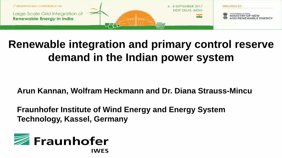
Objectives
1 • Estimation of FCR within Indian national grid
2 • Estimated FCR analyzed for peak load by
creating disturbance with H↓ due to RES
3 • Above analysis carried out for deployment of
FCR with different ramp rates
FCR - Frequency Containment Reserve or primary control reserve RES – Renewable Energy Sources H – Aggregated inertia constant

Slide 5 Submission ID - GIZ17-26
Criteria for FCR dimensioning (acc. to ENTSO-E) ENTSO-E - European Network of Transmission System Operators for Electricity
Criteria: Maximum expected instantaneous active power deviation (N-1):
Loss of the largest power plant/ line section/ bus bar/ HVDC interconnector (loss of the largest load at one connection point).
In larger systems like continental Europe (or all-India) Subsequent failures have to be considered (N-2).For Europe,
loss of largest unit 1.5 GW.
for N-2 criterion3 GW.
Additional risk: system split with highly imbalanced grid areas.

Slide 6 Submission ID - GIZ17-26
System split – Example Turkey 2015-03
+ approx. 4700 MW - approx. 4700MW
ENTSO-E, "Report on Blackout in Turkey on 31st March 2015," September 2015.

Slide 7 Submission ID - GIZ17-26
System Modeling
Using swing equation of a synchronous machine to small perturbation
The frequency-dependent characteristic of a composite load
FCR conventional generation turbine
modelling is considered. Governor adjusts the turbine valve to bring the
frequency back to the scheduled value when load (↑↓)
Generation-load modelling
Turbine and governor modelling
H is inertia constant in MWs/MVA G is total rated power of the generators in MVA ωo is reference grid frequency (i.e. 314 rad/s) ΔPm is small change in mechanical power in MW ΔPe is small change in electrical power in MW ∆ωr is small change in angular speed of the rotor in rad/s ΔPL is non-frequency sensitive load change in MW D∆ωr is frequency sensitive load change in MW Tg is governor time constant R is speed regulation or droop in Hz/MW Th is time constant of the turbine
∆P𝑒𝑒= ∆PL + D ∙ ∆ω𝑟𝑟

Slide 8 Submission ID - GIZ17-26
Estimation of FCR
IEGC says, large generating complex (>=3000 MW) should satisfy (N-2).
Outage of 8000 MW assumed as a credible contingency
FCR of 8000 MW estimated for the entire synchronous area.
IEGC – Indian Electricity Grid Code SPS – System Protection Scheme
Map - as on 30.06.2014

Slide 9 Submission ID - GIZ17-26
Estimation of FCR
IEGC says, large generating complex (>=3000 MW) should satisfy (N-2).
Outage of 8000 MW assumed as a credible contingency
FCR of 8000 MW estimated for the entire synchronous area.
IEGC – Indian Electricity Grid Code SPS – System Protection Scheme
Map - as on 30.06.2014
Slide 10 Submission ID - GIZ17-26
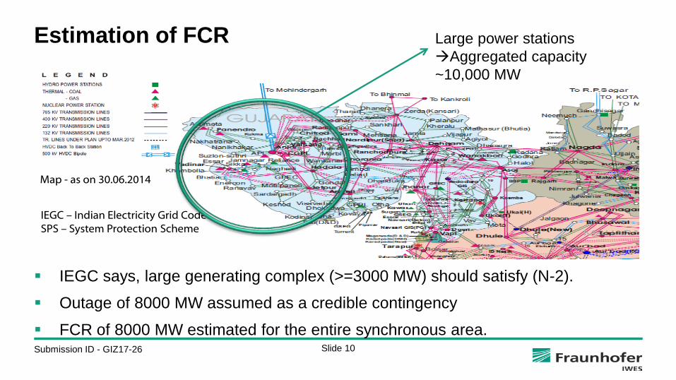
Estimation of FCR
IEGC says, large generating complex (>=3000 MW) should satisfy (N-2).
Outage of 8000 MW assumed as a credible contingency
FCR of 8000 MW estimated for the entire synchronous area.
Large power stations Aggregated capacity ~10,000 MW
IEGC – Indian Electricity Grid Code SPS – System Protection Scheme
Map - as on 30.06.2014

Slide 11 Submission ID - GIZ17-26
Estimation of FCR
IEGC says, large generating complex (>=3000 MW) should satisfy (N-2).
Outage of 8000 MW assumed as a credible contingency
FCR of 8000 MW estimated for the entire synchronous area.
Large power stations Aggregated capacity ~10,000 MW
IEGC – Indian Electricity Grid Code SPS – System Protection Scheme
(N-1) SPS Map - as on 30.06.2014

Slide 12 Submission ID - GIZ17-26
Case Studies
Scenarios Disturbance
[PL] (MW)
Peak Load [G]
(GW)
Self-regulating loads
[D] (MW/Hz)
Inertia [H]
(MWs/MVA)
Rate limiter or ramp rate (MW/s)
Droop [1/R]
(MW/Hz)
Scenario 1
8000 150
4500
6 5 4 3 2 1
266.667
40000
Scenario 2
6000 Scenario 3 *400
Scenario 4 **800
* 400 MW/s rate limiter means, all the FCR activated within 20s (i.e. 8000 MW/20s) **800 MW/s rate limiter means, all the FCR activated within 10s (i.e. 8000 MW/10s)
Results judged on below factors: 1. Maximum frequency deviation (+/-1Hz)
because load shedding at 48.8 Hz 2. Time to reach the minimum frequency
point

Slide 13 Submission ID - GIZ17-26
Case Studies Scenario 1
FCR of 8000 MW activated within 30s Step load disturbance 8000 MW

Slide 14 Submission ID - GIZ17-26
Case Studies Scenario 2
FCR of 8000 MW activated within 30s Step load disturbance 8000 MW
Slide 15 Submission ID - GIZ17-26
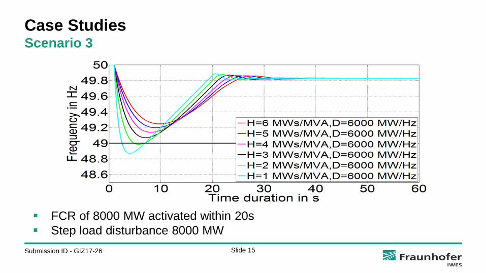
Case Studies Scenario 3
FCR of 8000 MW activated within 20s Step load disturbance 8000 MW
Slide 16 Submission ID - GIZ17-26
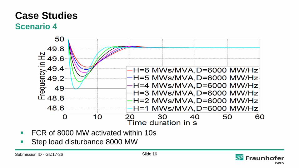
Case Studies Scenario 4
FCR of 8000 MW activated within 10s Step load disturbance 8000 MW

Slide 17 Submission ID - GIZ17-26
Conclusion
Dimensioning of FCR N-2 criterion and system split
RES ↑ H ↓ and Δf ↑and also the time to reach the minimum frequency point is faster.
D↑ Δf ↓ Δf recovers very fast with a better quasi-steady state Δf with the help of FCR.
In future, RES↑, there is a necessity to provide the inertial response.
This could be provided from RES as FFR which can be activated immediately (< 2 s) for a time span of up to several seconds after the disturbance.
The FFR can be provided by RES by means of deloaded operation, energy storage systems (ESS) and other technologies.
Δf - Frequency deviation FFR – Fast Frequency Reserve
Slide 18 Submission ID - GIZ17-26
Arun Kannan, M.Sc. Group of Power System Dynamics and Control Fraunhofer Institute for Wind Energy and Energy System Technology IWES Königstor 59 | 34119 Kassel | Germany Phone +49 561 7294-145 [email protected]

Slide 19 Submission ID - GIZ17-26
Back up
Slide 20 Submission ID - GIZ17-26
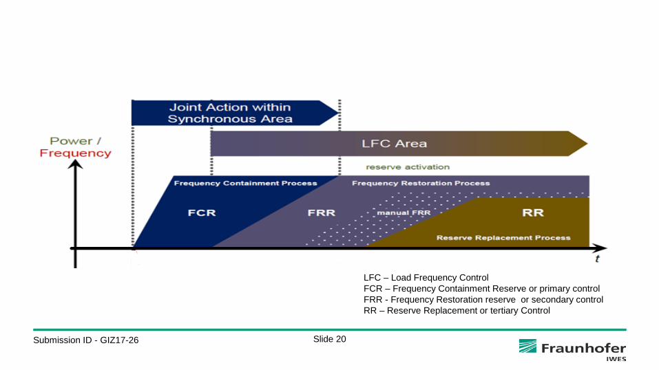
LFC – Load Frequency Control FCR – Frequency Containment Reserve or primary control FRR - Frequency Restoration reserve or secondary control RR – Reserve Replacement or tertiary Control