Embed Size (px)
Citation preview
Renewable Energy from Gasification of Refuse Derived Fuel
EPR Doc. 1042019 Proprietary Information 1
Renewable Energy from Gasification
of
Refuse Derived Fuel
January 2019
EnviroPower Renewable, Inc.
7301A Palmetto Parkway Rd.
Suite 206B Boca Raton, FL 33433
www.eprenewable.com
Components Represented by
“LoNOx Burner”
Renewable Energy from Gasification of Refuse Derived Fuel
EPR Doc. 1042019 Proprietary Information 2
Contents
1.0 Executive Summary ......................................................................................................................... 3
2.0 Background....................................................................................................................................... 4
3.0 Gasification ....................................................................................................................................... 6
3.1 Gasification vs. Landfill and Incineration for Treatment of Solid Waste ............................... 8
3.2 Environmental Advantages of Gasification-Based Waste to Energy Conversion ............... 9
4.0 EPR Gasification Technology ....................................................................................................... 11
4.1 Steam Rankine Cycle Power Generation ............................................................................... 14
4.2 Heat and Material Balance ........................................................................................................ 15
4.3 Rotary Kiln Gasifiers .................................................................................................................. 16
4.4 Examples of EPR Gasification Power Plant Specifications and Capacities ....................... 21
5.0 References and Bibliography ....................................................................................................... 23
Renewable Energy from Gasification of Refuse Derived Fuel
EPR Doc. 1042019 Proprietary Information 3
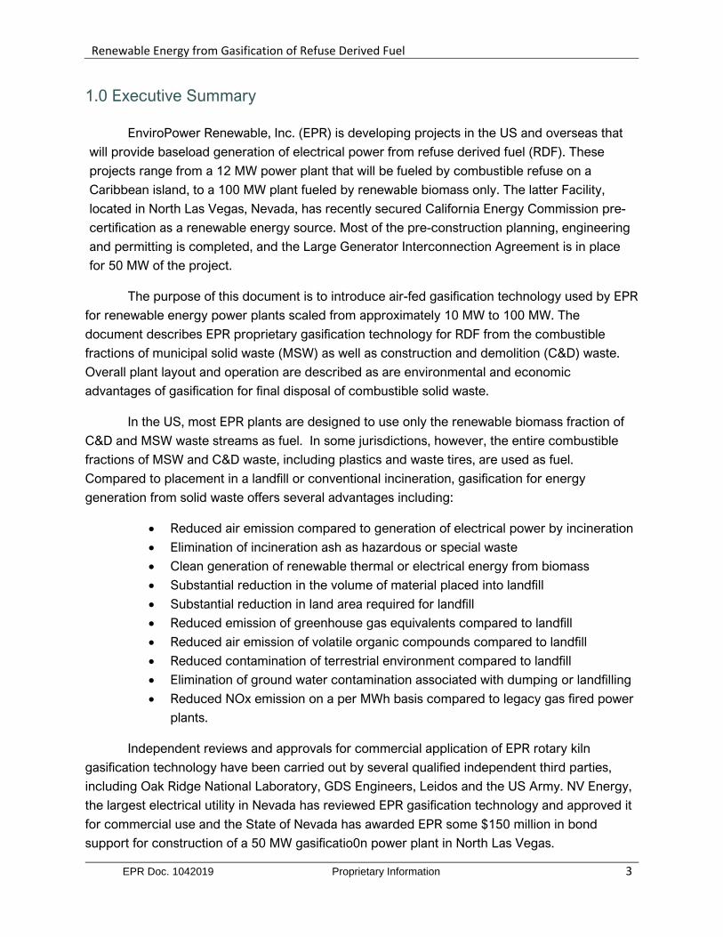
1.0 Executive Summary
EnviroPower Renewable, Inc. (EPR) is developing projects in the US and overseas that
will provide baseload generation of electrical power from refuse derived fuel (RDF). These
projects range from a 12 MW power plant that will be fueled by combustible refuse on a
Caribbean island, to a 100 MW plant fueled by renewable biomass only. The latter Facility,
located in North Las Vegas, Nevada, has recently secured California Energy Commission pre-
certification as a renewable energy source. Most of the pre-construction planning, engineering
and permitting is completed, and the Large Generator Interconnection Agreement is in place
for 50 MW of the project.
The purpose of this document is to introduce air-fed gasification technology used by EPR
for renewable energy power plants scaled from approximately 10 MW to 100 MW. The
document describes EPR proprietary gasification technology for RDF from the combustible
fractions of municipal solid waste (MSW) as well as construction and demolition (C&D) waste.
Overall plant layout and operation are described as are environmental and economic
advantages of gasification for final disposal of combustible solid waste.
In the US, most EPR plants are designed to use only the renewable biomass fraction of
C&D and MSW waste streams as fuel. In some jurisdictions, however, the entire combustible
fractions of MSW and C&D waste, including plastics and waste tires, are used as fuel.
Compared to placement in a landfill or conventional incineration, gasification for energy
generation from solid waste offers several advantages including:
• Reduced air emission compared to generation of electrical power by incineration
• Elimination of incineration ash as hazardous or special waste
• Clean generation of renewable thermal or electrical energy from biomass
• Substantial reduction in the volume of material placed into landfill
• Substantial reduction in land area required for landfill
• Reduced emission of greenhouse gas equivalents compared to landfill
• Reduced air emission of volatile organic compounds compared to landfill
• Reduced contamination of terrestrial environment compared to landfill
• Elimination of ground water contamination associated with dumping or landfilling
• Reduced NOx emission on a per MWh basis compared to legacy gas fired power
plants.
Independent reviews and approvals for commercial application of EPR rotary kiln
gasification technology have been carried out by several qualified independent third parties,
including Oak Ridge National Laboratory, GDS Engineers, Leidos and the US Army. NV Energy,
the largest electrical utility in Nevada has reviewed EPR gasification technology and approved it
for commercial use and the State of Nevada has awarded EPR some $150 million in bond
support for construction of a 50 MW gasificatio0n power plant in North Las Vegas.
Renewable Energy from Gasification of Refuse Derived Fuel
EPR Doc. 1042019 Proprietary Information 4
2.0 Background
While great progress has been made in the deployment of renewable energy generation
from wind and solar, many of the same jurisdictions are now facing new challenges in
developing and operating electrical grids to cope with the increasing proportion of renewable
energy from these intermittent sources.
Baseload Power and Grid Stability: Rapid increases in the use of intermittently
available sources of power, together with a reluctance to continue use of fossil fuel fired
baseload power plants, has created areas of instability on some western State power grids. In
short, intermittent renewable energy sources do not always generate power when and where it
is needed. While the use of battery storage can partially address the problems of intermittent
power sources, baseload (24/7/365) generation of renewable power at a competitive price is
needed to fully stabilize the grid and provide the reliability demanded by consumers. With poor
prospects for new hydro, viable baseload renewable energy options are effectively limited to
geothermal and biomass thermal conversion.
Distributed Generation and Microgrids: In many areas, movement away from large
coal fired power plants, in favor of smaller capacity and intermittent renewable energy
generation, is placing a strain on tradition long distance power transmission systems. The 10MW
to 100 MW baseload gasification power plants described here are an ideal component of the
distributed generation and microgrid systems that will help stabilize the electrical power
infrastructure as the US moves away from large centralized fossil fuel generation plants.
Gasification in Integrated Solid Waste Management Systems: Recent decisions by
China to greatly reduce or discontinue import of combustible recyclable materials from other
countries, and mainly the US, is placing increasing pressure on existing landfills. This change in
the recyclables market will further exacerbate already acute disposal problems in many cities,
especially in the Northeast, where MSW is already being sent out of state for disposal. Adaptive
measures, including deployment of gasification waste to energy plants, will be required to
manage disposal of domestic combustible MSW in many areas of the country. Combustible
fractions of MSW and C&D are comprised primarily of biomass (wood, cardboard, paper, green
waste, etc.) and can be sorted to yield a clean biomass only fuel that is ideal for gasification. It is
this 100% renewable fuel for which the 100 MW North Las Vegas described in this document
was designed.
Renewable Energy from Gasification of Refuse Derived Fuel
EPR Doc. 1042019 Proprietary Information 5
In some jurisdictions, waste to energy gasification is of interest primarily as a component
of an integrated and sustainable solid waste management system. In these applications, the
waste to energy plant is generally co-located with a landfill. In areas where landfills have become
environmental hazards due to objectionable odors, smoke from landfill fires or blowing fugitive
trash, a gasification power plant can be an important component in remediation.
These landfills can be mined for combustible materials that would otherwise be a
substrate for anaerobic decomposition giving rise to toxic air emissions, or fuel for fires.
Processing of incoming waste streams can be designed so that combustible materials are
diverted to the gasification power plant, metals are reclaimed for recycling, and only inert non-
recyclable materials are placed in the landfill. In areas where the MSW includes a great deal of
wet organic matter, this material (mainly food waste) can be dried before gasification or treated
by anaerobic digestion to produce a biogas and a compost material.
Renewable Energy Credits for RDF from Combustible Mixed Waste: In many EU
jurisdictions, renewable energy credits, or their equivalent, can be earned by waste to energy
plants that use RDF that includes plastics, waste oil, tires and other fossil carbon containing
materials. Fossil carbon materials such as coal and oil can be distinguishable from
contemporary carbon (plant fiber) by determination of the relative abundance of carbon 14
(14C) to carbon 12 (12C) contained in the material (Aylott, 2011). Carbon 14 is a naturally
occurring and unstable isotope, formed in the upper atmosphere. Carbon 14 undergoes
radioactive decay to form carbon 12 with a half-life of some 5,700 years.
It is therefore possible to determine whether carbon is contemporary (renewable:
incorporated from the atmosphere into plant life within the last few centuries) or fossil, (non-
renewable: incorporated into plant material millions of years ago.) The determination is done by
measuring the 14C to 12C abundance ratio in the stack gas of thermal plants using waste as fuel.
For waste to energy plants in the EU, typically 60% to 70% of the waste used for fuel is
contemporary carbon or biomass.
Depending on local laws, renewable energy credits can be allotted for the percentage of
carbon that is renewable, since this renewable carbon offsets the fossil carbon that would
otherwise be used to generate the same amount of electrical energy.
Renewable Energy from Gasification of Refuse Derived Fuel
EPR Doc. 1042019 Proprietary Information 6
3.0 Gasification
Gasification is a process wherein carbonaceous materials are dissociated at high
temperatures in an oxygen-starved thermal reactor to form a fuel gas that is mainly composed of
carbon dioxide, carbon monoxide, hydrogen, methane, and water vapor. If the thermal reactor
is air fed (as opposed to oxygen fed only), the fuel gas also contains inert nitrogen (N2) and is
referred to a producer gas. The fuel gas product of oxygen fed gasification is synthesis gas, or
syngas. In this document, the producer gas will be referred to as fuel gas.
Gasification reactions take place at somewhat lower temperatures than complete
combustion and require less mass flow through the gasification reactor. This reduced mass flow
means that gasification reactors can be smaller than incinerators for a given rate of fuel use or
thermal output. The fuel gas from the main reactor can be reformed to crack tars prior to
combustion in the well-controlled LoNOx burner developed by EPR. In EPR power plants, the
thermal energy from burning of the fuel gas is used to make steam, which drives a steam turbine
to generate power. This steam Rankine cycle process is described in more detail below.
Compared to incineration for thermal treatment of MSW, gasification is inherently:
- more thermally efficient than incineration;
- cleaner than incineration, with fewer air emissions including less entrained particulate,
and lower emissions of nitrogen oxides (NOx), as well as lower concentrations
of other pollutants in the flue gas;
- less expensive than incineration to build and operate;
- capable of producing commercially beneficial by products. In addition, MSW
gasifiers can be designed to produce a low carbon, inert and non-leachable
slag or vitreous frit instead of a leachable bottom ash (as is produced by
incinerators). Residual sintered material can be beneficially used in cement
making, or as an aggregate for cement blocks or for fill materials.
Proprietary EPR flue gas recycle and LoNOx burner further enhance the advantages of
gasification as compared to incineration.
Renewable Energy from Gasification of Refuse Derived Fuel
EPR Doc. 1042019 Proprietary Information 7
Modern air fed gasifiers can operate on various forms of combustible solid waste and
biomass. Gasification, steam power generation, and flue gas cleaning equipment of the type
used by EPR have been in successful commercial operation for decades, and much of it for
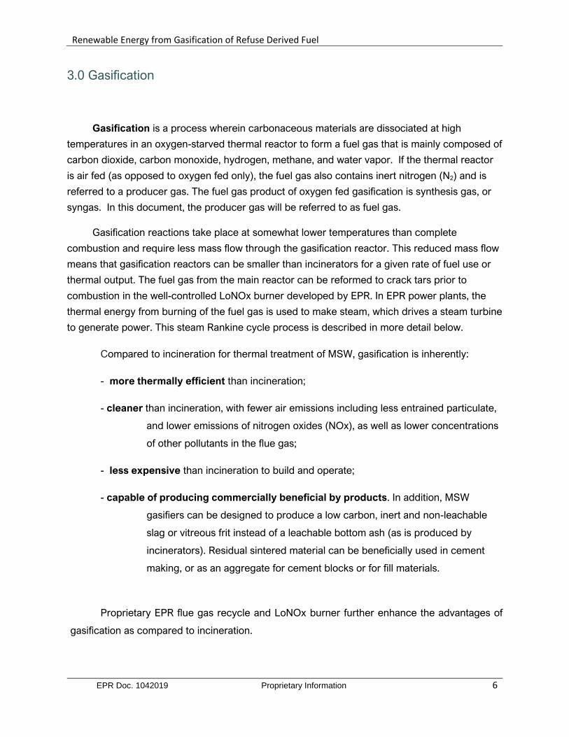
more than a century. Figure 3.1 below illustrates the main differences between incineration
and gasification in terms of gas phase and solid phase emissions. As indicated in Figure
3.1, benefits achieved with gasification as compared to incineration include:
1. Less oxidation of fuel bound nitrogen to form NOx;
2. Reduction in fuel borne NOx emissions from flue gas recycle
3. Little or no "thermal NOx" is generated by properly operated gasifiers;
4. Reforming used in EPR gasification systems results in a relatively cleaner fuel gas
Figure 3.1. Conventional incineration compared to EPR LoNOx gasification system
Refo
rmer
Recycled
Flue Gas
Overfire
Air
Incineration:
- Operates with excess air
- Generates more PM, NOx VOC, etc.
- Equipment larger and more expensive
- Ash is generally special or hazardous waste
Gasification:
- Operates sub-stoichiometricly with much lower gas
flow through the main reactor
- Less particulate generated - and what is formed is
removed prior to combustion of the clean fuel gas,
generating less PM, NOx, CO2 , VOC s, and no Ozone
- Gasification systems are smaller and less expensive
- EPR ash is a clean, inert , non-leachable product
Figure 2.2 Comparison of gasification with incineration in terms of mass flow, and inherent emissions
Renewable Energy from Gasification of Refuse Derived Fuel
EPR Doc. 1042019 Proprietary Information 8
3.1 Gasification vs. Landfill and Incineration for Treatment of Solid Waste
Several studies have compared the relative environmental and economic impacts of
landfill placement, incineration and gasification for treatment and disposal of MSW. Such
studies, including those carried out by the USEPA (1996) and USDOE (2002) and Amec
Environmental UK (2011), as well as reports from Los Angeles (URS, 2005), Victoria, BC
(Stantec, 2011), BPA (2009), and a large study from Europe (Munster, 2009), show that
properly designed and operated air fed gasification systems are, by far, the most efficient and
cleanest thermal technology for converting solid waste to energy.
Banes (2003) and Zaman (2009) have provided life cycle assessments comparing
landfill, incineration and gasification as primary technologies for treatment and disposal of
MSW. Again, gasification ranked highest, overall, when considering the combined
characteristics of conversion efficiency, cost per unit of power generated, and favorable
environmental impact. Environmental advantages of thermal treatment of combustible waste, as
compared to landfill, have been confirmed by the USEPA, which has concluded that landfills are
an important source of fugitive methane gas (Thorneloe, 2012), which gas is some 25-fold more
effective as a greenhouse gas than carbon dioxide (CO2).
Thermal treatment of MSW is a well proven technology for producing renewable energy,
while greatly reducing the emission of methane and other greenhouse gases per unit mass of
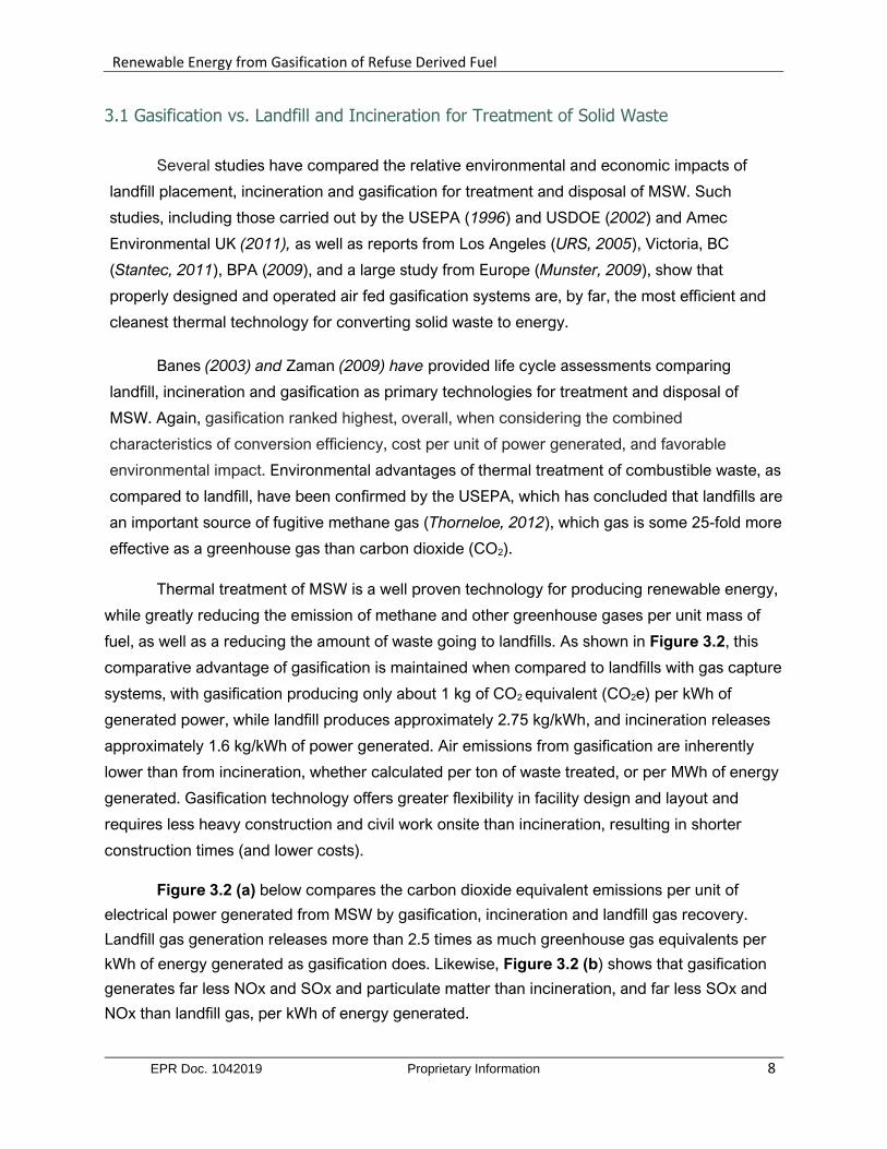
fuel, as well as a reducing the amount of waste going to landfills. As shown in Figure 3.2, this
comparative advantage of gasification is maintained when compared to landfills with gas capture
systems, with gasification producing only about 1 kg of CO2 equivalent (CO2e) per kWh of
generated power, while landfill produces approximately 2.75 kg/kWh, and incineration releases
approximately 1.6 kg/kWh of power generated. Air emissions from gasification are inherently
lower than from incineration, whether calculated per ton of waste treated, or per MWh of energy
generated. Gasification technology offers greater flexibility in facility design and layout and
requires less heavy construction and civil work onsite than incineration, resulting in shorter
construction times (and lower costs).
Figure 3.2 (a) below compares the carbon dioxide equivalent emissions per unit of
electrical power generated from MSW by gasification, incineration and landfill gas recovery.
Landfill gas generation releases more than 2.5 times as much greenhouse gas equivalents per
kWh of energy generated as gasification does. Likewise, Figure 3.2 (b) shows that gasification
generates far less NOx and SOx and particulate matter than incineration, and far less SOx and
NOx than landfill gas, per kWh of energy generated.
Renewable Energy from Gasification of Refuse Derived Fuel
EPR Doc. 1042019 Proprietary Information 9
Figure 3.2 (a,b) Relative greenhouse gas equivalent emissions (a) and the relative
emissions of NOx, SOx and particulate matter (b) per kWh or energy generated from
conversion of MSW by gasification, incineration and landfill
3.2 Environmental Advantages of Gasification-Based Waste to Energy Conversion
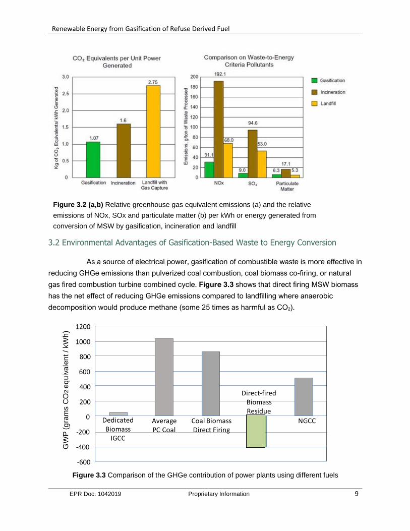
As a source of electrical power, gasification of combustible waste is more effective in
reducing GHGe emissions than pulverized coal combustion, coal biomass co-firing, or natural
gas fired combustion turbine combined cycle. Figure 3.3 shows that direct firing MSW biomass
has the net effect of reducing GHGe emissions compared to landfilling where anaerobic
decomposition would produce methane (some 25 times as harmful as CO2).
Figure 3.3 Comparison of the GHGe contribution of power plants using different fuels
GW
P(g
ram
s C
O2
eq
uiv
ale
nt / kW
h)
NGCC
Direct-fired BiomassResidue
Average PC Coal
Coal Biomass Direct Firing
Dedicated Biomass
IGCC
1200
1000
800
600
400
200
0
-200
-400
-600
Renewable Energy from Gasification of Refuse Derived Fuel
EPR Doc. 1042019 Proprietary Information 10
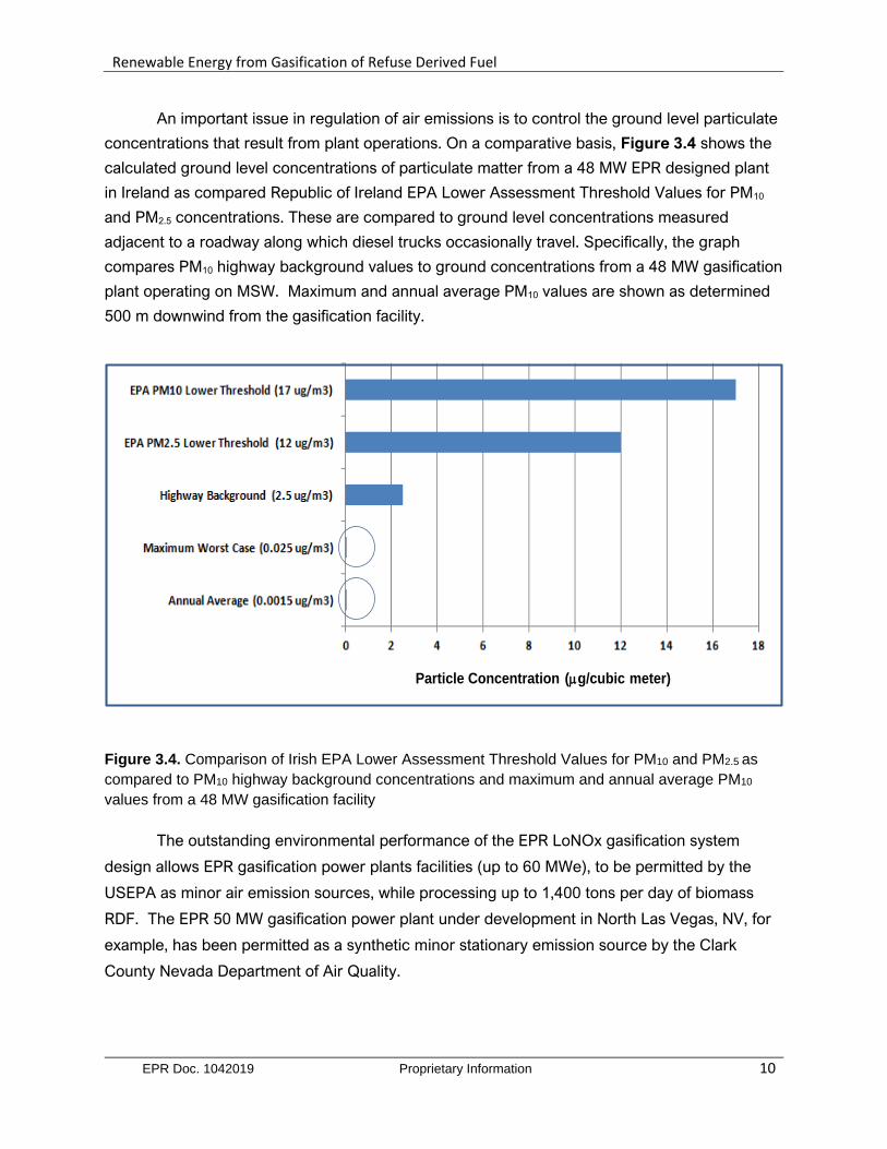
An important issue in regulation of air emissions is to control the ground level particulate
concentrations that result from plant operations. On a comparative basis, Figure 3.4 shows the
calculated ground level concentrations of particulate matter from a 48 MW EPR designed plant
in Ireland as compared Republic of Ireland EPA Lower Assessment Threshold Values for PM10
and PM2.5 concentrations. These are compared to ground level concentrations measured
adjacent to a roadway along which diesel trucks occasionally travel. Specifically, the graph
compares PM10 highway background values to ground concentrations from a 48 MW gasification
plant operating on MSW. Maximum and annual average PM10 values are shown as determined
500 m downwind from the gasification facility.
Figure 3.4. Comparison of Irish EPA Lower Assessment Threshold Values for PM10 and PM2.5 as
compared to PM10 highway background concentrations and maximum and annual average PM10
values from a 48 MW gasification facility
The outstanding environmental performance of the EPR LoNOx gasification system
design allows EPR gasification power plants facilities (up to 60 MWe), to be permitted by the
USEPA as minor air emission sources, while processing up to 1,400 tons per day of biomass
RDF. The EPR 50 MW gasification power plant under development in North Las Vegas, NV, for
example, has been permitted as a synthetic minor stationary emission source by the Clark
County Nevada Department of Air Quality.
Particle Concentration (mg/cubic meter)
Renewable Energy from Gasification of Refuse Derived Fuel
EPR Doc. 1042019 Proprietary Information 11
4.0 EPR Gasification Technology
EPR gasifier designs use proven off-the-shelf equipment in a proprietary process to
economically generate electricity from waste with the minimum environmental impact. The use
of proven equipment allows for a high level of reliability while simultaneously providing clean,
renewable base load power. Here we discuss the general features of EPR gasification systems.
EPR designed facilities use air-fed gasification for conversion of solid waste. Since these
facilities are paid to process their fuel, thermodynamic efficiency becomes relatively less
important as compared to thermal power plants that pay for fuel. This allows greater design
emphasis to be placed on system reliability and environmental performance.
Systems are individually designed based on the type of waste available, local altitude and
climactic conditions, and the availability of sufficient cooling water for a water-cooled condenser.
The process flow diagram shown below is included mainly to identify the main equipment
components of the thermal and power island sections of the plant and is not intended to be
enabling.
The EPR approach to gasification system design has been to start with commercially
proven equipment and then reconfigure that equipment by adding proprietary and industry
standard upgrades to improve the reliability, environmental performance and efficiency. Such
innovations include:
- reforming at high temperatures to crack any tars present in the raw fuel gas and
convert fuel born nitrogen into N2, greatly reducing NOx formation during combustion;
- staged fuel gas combustion to control flame temperature to eliminate formation of
thermal NOx;
- Increased residence time at temperature to allow for the increased reduction of NOx
species to inert molecular nitrogen, and destruction of dioxins and furans;
- use of a high temperature final stage of gasification for the elimination of carbon from
the bottom ash and consolidation of the ash;
- recycling a large portion of the flue gas for controlling temperature instead of
quenching with air, resulting in a much lower volume of gas passing through the flue gas
cleanup systems.
Renewable Energy from Gasification of Refuse Derived Fuel
EPR Doc. 1042019 Proprietary Information 12
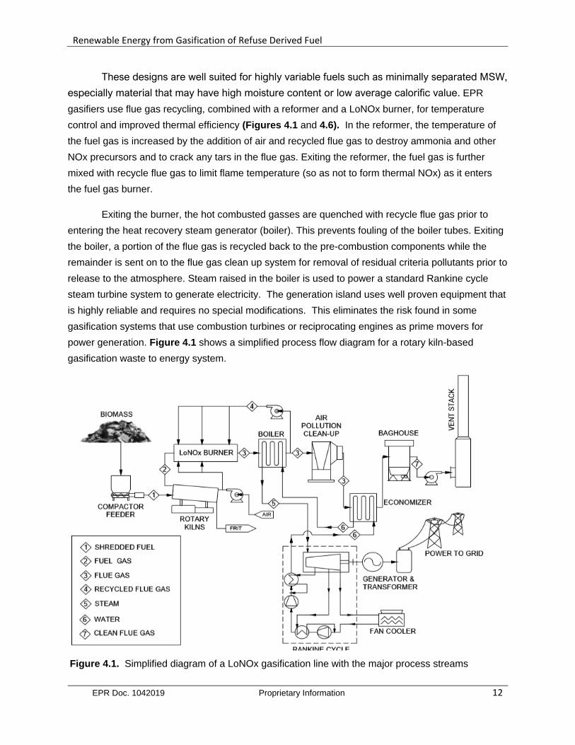
These designs are well suited for highly variable fuels such as minimally separated MSW,
especially material that may have high moisture content or low average calorific value. EPR
gasifiers use flue gas recycling, combined with a reformer and a LoNOx burner, for temperature
control and improved thermal efficiency (Figures 4.1 and 4.6). In the reformer, the temperature of
the fuel gas is increased by the addition of air and recycled flue gas to destroy ammonia and other
NOx precursors and to crack any tars in the flue gas. Exiting the reformer, the fuel gas is further
mixed with recycle flue gas to limit flame temperature (so as not to form thermal NOx) as it enters
the fuel gas burner.
Exiting the burner, the hot combusted gasses are quenched with recycle flue gas prior to
entering the heat recovery steam generator (boiler). This prevents fouling of the boiler tubes. Exiting
the boiler, a portion of the flue gas is recycled back to the pre-combustion components while the
remainder is sent on to the flue gas clean up system for removal of residual criteria pollutants prior to
release to the atmosphere. Steam raised in the boiler is used to power a standard Rankine cycle
steam turbine system to generate electricity. The generation island uses well proven equipment that
is highly reliable and requires no special modifications. This eliminates the risk found in some
gasification systems that use combustion turbines or reciprocating engines as prime movers for
power generation. Figure 4.1 shows a simplified process flow diagram for a rotary kiln-based
gasification waste to energy system.
Figure 4.1. Simplified diagram of a LoNOx gasification line with the major process streams
Renewable Energy from Gasification of Refuse Derived Fuel
EPR Doc. 1042019 Proprietary Information 13
Main steps in the overall process depicted in Figure 4.1 include:
• Sorting and processing of waste to make into Refuse Derived Fuel;
• Gasification of the Refuse Derived Fuel;
• Reforming of the resulting fuel gas to destroy pollutants;
• Combustion of the cleaned fuel gas controlled by recycled flue gas;
• Production of steam in a heat recovery boiler
• Production of electricity from one or more Steam Turbine Generators; and
• Treatment of flue gas from the Heat Recovery Boilers
• Sintering of the bottom ash residue to produce an inert, carbon free, solid residue
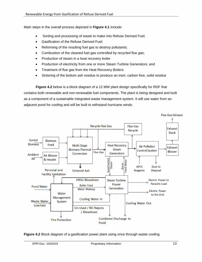
Figure 4.2 below is a block diagram of a 12 MW plant design specifically for RDF that
contains both renewable and non-renewable fuel components. The plant is being designed and built
as a component of a sustainable integrated waste management system. It will use water from an
adjacent pond for cooling and will be built to withstand hurricane winds.
Figure 4.2 Block diagram of a gasification power plant using once through waste cooling

Renewable Energy from Gasification of Refuse Derived Fuel
EPR Doc. 1042019 Proprietary Information 14
4.1 Steam Rankine Cycle Power Generation
The steam Rankine cycle is the industry standard for power production from thermal
energy. Heat from hot exhaust gases from the boiler generates super-heated steam in a heat
recovery steam generator (HRSG).
This steam is then used to power a steam turbine, which drives a generator, producing
electrical power. This system has been widely used since the invention of the steam turbine
over 100 years ago. The steam Rankine cycles currently produce around 90% of the world’s
electricity.
The power generation system used by EPR is custom designed for each project. A
custom HRSG is used, which is designed to handle the unique exhaust gases that come from
waste to energy systems. In this case, the HRSGs will generate steam at 400oC at a rate of
approximately 47 tons of steam per hour. This steam is piped to a turbine which, in the case of
the Caribbean plant described below, is designed to generate up to 12 MW of electricity.
The steam-water mixture leaving the turbine is converted back to water in a surface
condenser. This condenser is cooled using water. The condenser is important for maintaining a
low back pressure at the turbine exhaust, allowing it to run as efficiently as possible. The water
is then re-pressurized with a pump and returned to the HRSG to generate more steam.
Superheated steam, generated in the HRSG system, is piped for the two main uses in
the plant. The minor use is for process control steam, with a line providing steam to control the
thermal conversion of the fuel and the fuel gas generated, as needed. This is achieved by direct
injection of de-superheated steam into the rotating kiln gasifiers and the reformer.
The major use of steam in the plant is for power generation. Steam is expanded in a
turbine that is outfitted with two distinct extraction pressure level side-streams. The turbine
exhaust pressure is maintained by cooling the expanded, wet steam in an air-cooled condenser.
The steam cycle includes a dearator, which is used with extracted steam to preheat, and
strip air from, the boiler feed water. Components of the steam Rankine cycle system are shown
inside the dashed lines in Figure 4.1 above, and in the process flow diagram in Appendix I.
Renewable Energy from Gasification of Refuse Derived Fuel
EPR Doc. 1042019 Proprietary Information 15
4.2 Heat and Material Balance
Determination of heat and material (H&M) balance is a foundational calculation in the
design of thermal power plants. EPR conducts this critical design process using proprietary in-
house engineering software that essentially tracks each chemical component of the inflowing
fuel, air, water and reagents through the entire gasification and power generation process. Since
H&M balance calculations account for all the mass and energy entering and leaving the process
they are important in designing plant to operate efficiently with a wide variety of fuels.
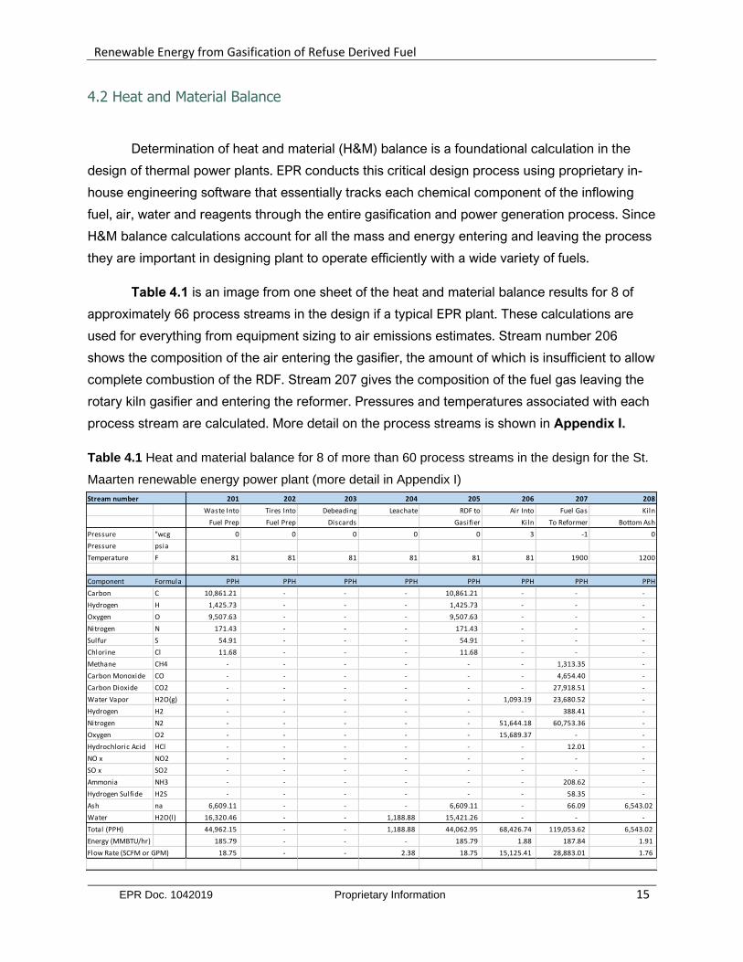
Table 4.1 is an image from one sheet of the heat and material balance results for 8 of
approximately 66 process streams in the design if a typical EPR plant. These calculations are
used for everything from equipment sizing to air emissions estimates. Stream number 206
shows the composition of the air entering the gasifier, the amount of which is insufficient to allow
complete combustion of the RDF. Stream 207 gives the composition of the fuel gas leaving the
rotary kiln gasifier and entering the reformer. Pressures and temperatures associated with each
process stream are calculated. More detail on the process streams is shown in Appendix I.
Table 4.1 Heat and material balance for 8 of more than 60 process streams in the design for the St.
Maarten renewable energy power plant (more detail in Appendix I)
Stream number 201 202 203 204 205 206 207 208
Waste Into Tires Into Debeading Leachate RDF to Air Into Fuel Gas Kiln
Fuel Prep Fuel Prep Discards Gasifier Kiln To Reformer Bottom Ash
Pressure "wcg 0 0 0 0 0 3 -1 0
Pressure psia
Temperature F 81 81 81 81 81 81 1900 1200
Component Formula PPH PPH PPH PPH PPH PPH PPH PPH
Carbon C 10,861.21 - - - 10,861.21 - - -
Hydrogen H 1,425.73 - - - 1,425.73 - - -
Oxygen O 9,507.63 - - - 9,507.63 - - -
Nitrogen N 171.43 - - - 171.43 - - -
Sulfur S 54.91 - - - 54.91 - - -
Chlorine Cl 11.68 - - - 11.68 - - -
Methane CH4 - - - - - - 1,313.35 -
Carbon Monoxide CO - - - - - - 4,654.40 -
Carbon Dioxide CO2 - - - - - - 27,918.51 -
Water Vapor H2O(g) - - - - - 1,093.19 23,680.52 -
Hydrogen H2 - - - - - - 388.41 -
Nitrogen N2 - - - - - 51,644.18 60,753.36 -
Oxygen O2 - - - - - 15,689.37 - -
Hydrochloric Acid HCl - - - - - - 12.01 -
NO x NO2 - - - - - - - -
SO x SO2 - - - - - - - -
Ammonia NH3 - - - - - - 208.62 -
Hydrogen Sulfide H2S - - - - - - 58.35 -
Ash na 6,609.11 - - - 6,609.11 - 66.09 6,543.02
Water H2O(l) 16,320.46 - - 1,188.88 15,421.26 - - -
Total (PPH) 44,962.15 - - 1,188.88 44,062.95 68,426.74 119,053.62 6,543.02
Energy (MMBTU/hr) 185.79 - - - 185.79 1.88 187.84 1.91
Flow Rate (SCFM or GPM) 18.75 - - 2.38 18.75 15,125.41 28,883.01 1.76
Renewable Energy from Gasification of Refuse Derived Fuel
EPR Doc. 1042019 Proprietary Information 16
4.3 Rotary Kiln Gasifiers
Rotary kilns (Figure 4.3) can serve as versatile and robust gasification reactors with
various designs for biomass and MSW being introduced over the last 40 years. The patented
and patent pending EPR countercurrent gasifier designs feature flue gas recycle and optical
sensors for tight control of gasifier
function over a wide range of fuel
quantities, qualities, particle sizes and
moisture content. These simply
designed gasifiers can operate on a
wide range of fuels and are easily
maintained. Their horizontal orientation
means they can be readily installed in
sheds or buildings.
Figure 4.3 Indoor installation of a rotary kiln
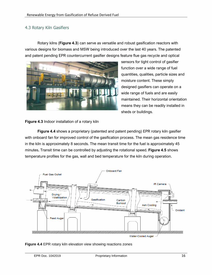
Figure 4.4 shows a proprietary (patented and patent pending) EPR rotary kiln gasifier
with onboard fan for improved control of the gasification process. The mean gas residence time
in the kiln is approximately 8 seconds. The mean transit time for the fuel is approximately 45
minutes. Transit time can be controlled by adjusting the rotational speed. Figure 4.5 shows
temperature profiles for the gas, wall and bed temperature for the kiln during operation.
Figure 4.4 EPR rotary kiln elevation view showing reactions zones

Renewable Energy from Gasification of Refuse Derived Fuel
EPR Doc. 1042019 Proprietary Information 17
Figure 4.5 Temperature profiles for kiln gas, wall and bed along in the four main reaction zones
Figure 4.6 is a color-coded layout of an EPR LoNOx. 4 kiln gasification line capable of
producing thermal energy to generate 50 MW on a fuel intake of some 1400 tons per day.
Figure 4.6. Layout of EPR LoNOx gasification line showing the gasifiers reformer and burners (Green),
heat exchangers (Blue) and air pollution control components (Red)
Components Represented by
“LoNOx Burner”

Renewable Energy from Gasification of Refuse Derived Fuel
EPR Doc. 1042019 Proprietary Information 18
Designs based on rotary kilns cost less to build and are robust with the ability to process
a wide variety of fuel materials in terms of composition, moisture content and particle size.
Figure 4.7 below is an isometric view of an EPR LoNOx gasification line showing tandem reactor
gasification units, steam generation boilers, heat exchangers, flue gas recycle, and flue gas
cleaning systems.
These gasification lines are modular. Figure 4.7 shows the thermal island only. The fuel
preparation area, air cooled condenser, and power island are not shown here. As shown, rotary
kiln gasifiers can be combined in modules comprised of up to 4 four kilns each. These are
connected to a single reformer, burner, boiler and air pollution control system. These systems
can be designed as LoNOx units with the capability to generate up to 50 MW or more
depending on fuel quality.
Figure 4.7. Isometric view of EPR LoNOx gasification line
Flue Gas Clean-up and Solid Residue Emissions: Because of lower mass flow through
a gasification reactor as compared to a conventional incinerator, flue gas from a gasifier
carries less particulate than that from an incinerator. Likewise, with flue gas recycle, NOx
emissions are inherently lower as well. The process units used in flue gas clean-up in
gasification are the same as those used in other carbon fuel plants.
Renewable Energy from Gasification of Refuse Derived Fuel
EPR Doc. 1042019 Proprietary Information 19
These include acid gas removal, selective catalytic or non-catalytic reduction,
electrostatic precipitator and a bag house. These units are selected for use as needed
depending on fuel, client preferences and local emission regulations. Using industry proven
commercial air pollution abatement equipment, an EPR 50 MW power plant qualifies as a
synthetic minor source under USEPA guidelines.
Solid by products of gasification, such as bottom ash and fly ash, have less
environmental impact than those from incinerators. There are several reasons for this. First,
gasification systems generally use sorted waste, as opposed to the mass burning of raw
unsorted waste in incinerators. This reduces the amount of heavy metals and chlorides that
enter the system, and thus reduces the amount found in the bottom ash and fly ash.
Secondly, gasification volatizes many of the water-soluble compounds found in bottom ash.
Incinerator bottom ash can contain up to 20% chlorides and 12% sulfates. These same
compounds in a gasification system are largely converted to gaseous HCl or H2S and removed
in the flue gas cleanup system. These higher concentrations of water-soluble compounds in
incinerator ash make it highly leachable and render it useless for most commercial
applications.
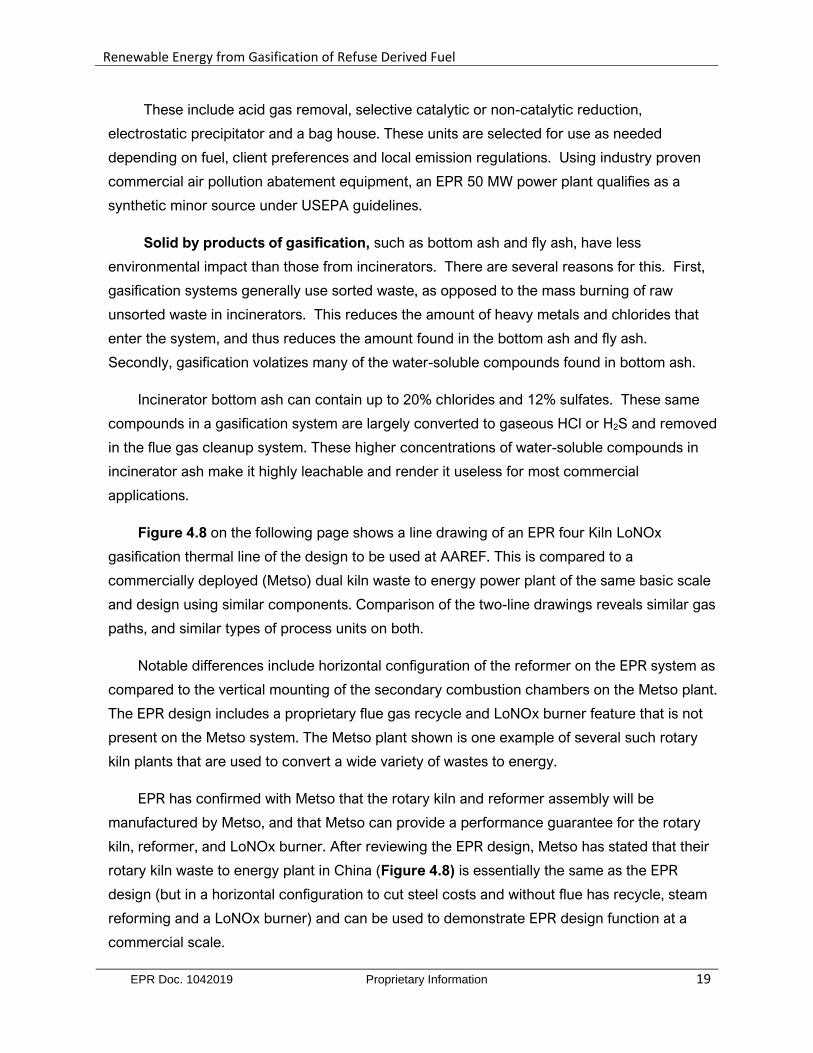
Figure 4.8 on the following page shows a line drawing of an EPR four Kiln LoNOx
gasification thermal line of the design to be used at AAREF. This is compared to a
commercially deployed (Metso) dual kiln waste to energy power plant of the same basic scale
and design using similar components. Comparison of the two-line drawings reveals similar gas
paths, and similar types of process units on both.
Notable differences include horizontal configuration of the reformer on the EPR system as
compared to the vertical mounting of the secondary combustion chambers on the Metso plant.
The EPR design includes a proprietary flue gas recycle and LoNOx burner feature that is not
present on the Metso system. The Metso plant shown is one example of several such rotary
kiln plants that are used to convert a wide variety of wastes to energy.
EPR has confirmed with Metso that the rotary kiln and reformer assembly will be
manufactured by Metso, and that Metso can provide a performance guarantee for the rotary
kiln, reformer, and LoNOx burner. After reviewing the EPR design, Metso has stated that their
rotary kiln waste to energy plant in China (Figure 4.8) is essentially the same as the EPR
design (but in a horizontal configuration to cut steel costs and without flue has recycle, steam
reforming and a LoNOx burner) and can be used to demonstrate EPR design function at a
commercial scale.
Renewable Energy from Gasification of Refuse Derived Fuel
EPR Doc. 1042019 Proprietary Information 20
Induced Draft Fan
Heat Recovery Boiler
Secondary Combustion Chamber
Rotary Kiln
Feed Hopper
Ram Loader
Emergency Stack
Baghouse
Gas Conditioning Tower
Wet Scrubbers
Induced Draft Fan
Exhaust Stack
EPR 50 MW Rotary Kiln Gasification Line
Figure 4.8. (Top) Line drawing of EPR 50 MW Gasification Thermal Island (Bottom) Image and line drawing of commercial dual kiln waste to energy power plant of a design similar to the EPR system
Renewable Energy from Gasification of Refuse Derived Fuel
EPR Doc. 1042019 Proprietary Information 21
Flue Gas Clean-up and Solid Residue Emissions: Because of lower mass flow through a
gasification reactor as compared to a conventional incinerator, flue gas from a gasifier carries less
particulate than that from an incinerator. Likewise, with flue gas recycle, NOx emissions are
inherently lower as well. The process units used in flue gas clean-up in gasification are the same as
those used in other carbon fuel plants. These include acid gas removal, selective catalytic or non-
catalytic reduction, electrostatic precipitator and a bag house. These units are selected for use as
needed depending on fuel, client preferences and local emission regulations. Using industry proven
commercial air pollution abatement equipment, an EPR 50 MW power plant qualifies as a synthetic
minor source under USEPA guidelines.
Solid by products of gasification, such as bottom ash and fly ash, have less
environmental impact than those from incinerators. There are several reasons for this. First,
gasification systems generally use sorted waste, as opposed to the mass burning of raw unsorted
waste in incinerators. This reduces the amount of heavy metals and chlorides that enter the system,
and thus reduces the amount found in the bottom ash and fly ash. Secondly, gasification volatizes
many of the water-soluble compounds found in bottom ash. Incinerator bottom ash can contain up
to 20% chlorides and 12% sulfates. These same compounds in a gasification system are largely
converted to gaseous HCl or H2S and removed in the flue gas cleanup system. These higher
concentrations of water soluble compounds in incinerator ash make it highly leachable and render it
useless for most commercial applications.
4.4 Examples of EPR Gasification Power Plant Specifications and Capacities
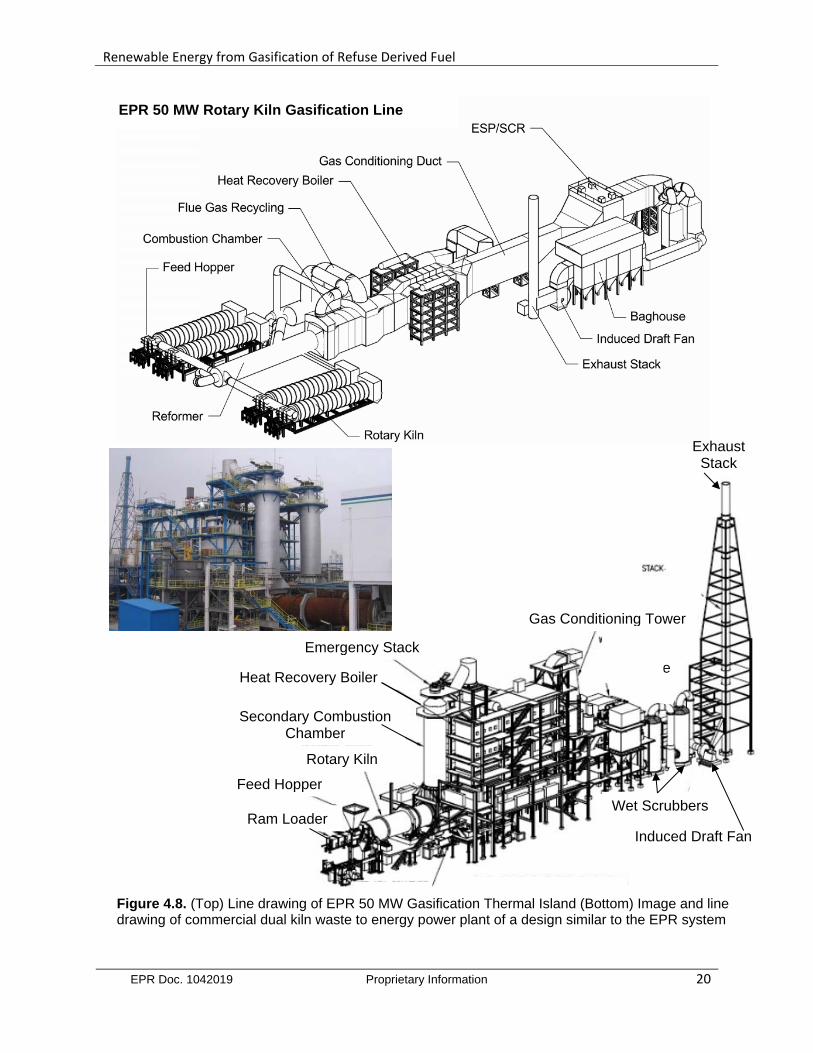
North Las Vegas 100 MW: Figure 4.9 shows an elevation view rendering of the plant
superimposed on a ground level image of the property in North Las Vegas, NV.
Figure 4.9 Ground level elevation rendering of the EPR 50 MW biomass gasification facility in North Las Vegas
Renewable Energy from Gasification of Refuse Derived Fuel
EPR Doc. 1042019 Proprietary Information 22
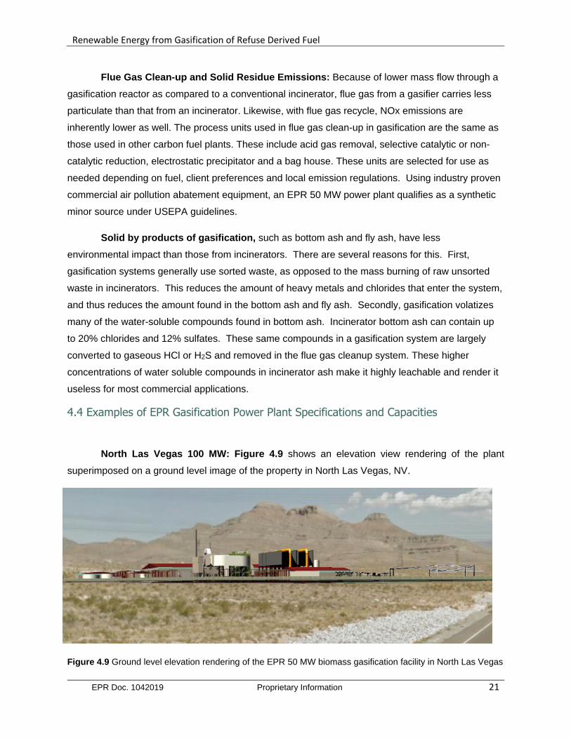
The overall site layout provides space for two 50 MW gasification lines to be constructed.
Plant capacities and specifications are shown in the Table 4.1. The renewable energy
generation plant in Las Vegas will be comprised of two 50 MW gasification lines, as described
above, each capable of autonomous operation. These Rankine cycle power plants will be
backed up with 42 MW of natural gas fired combustion gas turbines generation capacity. The
gas turbine generators will also be available for peaking power operation when not in use for
back-up power generation. As shown, the plant will also have Black Start capability provided by
a natural gas fired, battery started, reciprocating engine genset that will have the capability to
crank the combustion gas turbines. Key plant specifications and capacities for the 100 MW
gasification line module described above are shown in Table 4.1.
Table 4.1. Selected power plant design specifications and capacities
Independent reviews and approvals for commercial application of EPR rotary kiln
gasification technology have been carried out by several qualified independent third parties,
including Oak Ridge National Laboratory, GDS Engineers and the US Army. NV Energy, the
largest electrical utility in the State of Nevada has electrical utility in the State of Nevada has
reviewed EPR gasification technology and approved it for commercial use, and the State of
Nevada has approved EPR technology for some $150 million in bond support by the State for
the construction of a 50 MW generation facility in Las Vegas. EPR gasification technology has
also been approved for construction wraps by at least two EPCs and for funding by several
leading infrastructure funds including funds managed by Piper Jaffrey.
Specification Value
Gasifiers for 100 MW (nameplate) Gasification Line
Two 4 x Rotary Kilns
with Flue Gas Recycle
Gasification Line (nameplate) Generating Capacity
50 MW per line / 100MW total
Back-up and Demand Power Capacity (Total) 42 MW
Start-up / Black Start / Demand Power Fuel Natural Gas
Biomass Processing Capacity Up to 3000 Tpd
Feeder Line Output Voltage 138 kV
Permitted Net Power to the Grid 87 MW
Anticipated Average Net Power to the Grid 83.2 MW
Renewable Energy from Gasification of Refuse Derived Fuel
EPR Doc. 1042019 Proprietary Information 23
5.0 References and Bibliography
Amec Environmental UK (2011) Industrial Emissions of Nanoparticles and Ultrafine Particles
European Commission Final Report
http://ec.europa.eu/environment/industry/stationary/pdf/27924.pdf
Aylott, M (2011) Calculating the Renewable Fraction of Energy from Waste
http://biomassmagazine.com/articles/5754/calculating-the-renewable-fraction-of-energy-from-waste
Bain, R.L., et al., Biopower Technical Assessment: State of the Industry and Technology. 2003, National
Renewable Energy Laboratory.
BPA (2009) Evaluation of Emissions from Thermal Conversion Technologies Processing Municipal Solid
Waste and Biomass: Final Report (2009) Bioenergy Producers Association
http://socalconversion.org/pdfs/UCR Emissions Report 62109.pdf
Münster, M (2009) Energy Systems Analysis of Waste to Energy Technologies by use of Energy
PLAN, Danish Technical Research Counsel; ISBN 978-87-550-3719-9
http://orbit.dtu.dk/fedora/objects/orbit:81741/datastreams/file 4069900/content
Stantec (2011): Waste to Energy: A Technical Review of Municipal Solid Waste Thermal Treatment
Practices Final Report (2011) Environmental Quality Branch Victoria BC
http://www.env.gov.bc.ca/epd/mun-waste/reports/pdf/BCMOE-WTE-Emissions-final.pdf
Thorneloe, SA (2012) U.S. Trends in Solid Waste Management and GHG Emissions Health and
Environmental Concerns for Landfills ,Berlin Germany
http://www.umweltbundesamt.de/sites/default/files/medien/421/dokumente/us epa swm and ghg
emission.pdf
USDOD (2004) US Department of Defense: Solid Waste Incineration UFC 3-240-05A
USDOE (2002): Gasification Markets and Technologies – Present and Future: An Industry
Perspective USDOE Report DOE/FE-0447
USEPA (2009) Gasification and Renewable Energy
http://www.epa.gov/osw/hazard/wastemin/minimize/energyrec/renew.htm
URS (2005): Summary Report: Evaluation of Alternative Solid Waste Processing Technologies. City
of Los Angeles Dept of Public Works. Prepared by URS Corporation, Los Angeles, CA.
http://www.lacitysan.org/solid resources/strategic programs/alternative tech/PDF/summary report. pdf
Zaman, A U (2010) Comparative study of municipal solid waste treatment technologies
using life cycle assessment method Int. J. Environ. Sci. Tech., 7 (2), 225-234, Spring 2010
ISSN: 1735-1472 http://link.springer.com/article/10.1007%2FBF03326132#page-1
MacKay, G. etal (2010) Use of Incineration MSW Ash: A Review, Sustainability, 2, 1943-1968