Embed Size (px)
DESCRIPTION
an tutorial for rendering in rhino
Citation preview
macdesignstudio
Design, Computing, and Urbanism
DPI and Output Size – what you needto know
Ok, so I know that I promised I’d come up with a post about how to pull allthe previous discussed techniques together, and trust me, I will. However aconversation at the office yesterday arose and I thought it’d be a reallygood thing to post about…output size and how large should we be savingour images.
Keys to remember:
1) It’s all about pixels!
Remember this, as it’s very important and the common factor between
most of what we’ll talk about for the rest of the post.
2) There’s going to need to be a bit of math,but trust me…it’s not that hard.
Go back to your days of Algebra I and you’ll be fine. We’ll be using theequation DPI * Inches = Pixels. From this equation, if we have 2 of the 3variables, we can always solve for the other. More on this to come later.
4 02 2012

(http://macdesignstudio.files.wordpress.com/2012/02/image-size-screen1.jpg)
3) It’s about the distance at which the object isgoing to be seen.
The human eye can differentiate pixels at about 120-150 dpi when beingheld and read in one’s hand. As you step further away, less definition isneeded. Think about those various pixelated images that when you getclose you see they are a montage of small pictures, but when you standback appear to be one image. This is exactly the same principle.

(http://macdesignstudio.files.wordpress.com/2012/02/bush-copy.jpg)Image courtesy of Sabri Farouki at http://sabrifarouki.com
(http://sabrifarouki.com)
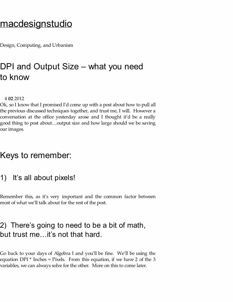
Also, as you get older and are in lower light, you will be able to differentiateless dpi. The other thing to keep in mind is that vector based informationdone in a raster based program will show effects dependent on the dpi. Thebest example of this is text in Photoshop. While working with a 72 dpiimage, the text will look fairly pixelated and jagged. The reason is becausethe linework of the font has to fit within the pixel. For this reason, I’dsuggest working with text in either Indesign or Illustrator. Working inPhotoshop will force you to use a higher resolution (200dpi-300 dpi)because of the text issue which will force you to render or use a largerimage, negating the speed of using the smaller rendering or image. Seebelow for an example of the pixelated text and how the text needs to fitwithin a pixel as opposed to remaining vector based.
(http://macdesignstudio.files.wordpress.com/2012/02/text-raster.jpg)Text in Photoshop - click to see full size
4) What is the output media going to be? Print? Video? Billboard?
Typical video/computer/projectors use a 72 dpi standard. HD video uses1920 px X 1080 px (hence your tv is a 1080). The computer monitor orprojector will have their own resolution. The laptop I’m writing this on forexample is 1400 x 900 px. As previously stated, printed material for handouts should be min. 150 dpi and then printed presentation boards could godown to 100 dpi. If you’re looking to create a billboard or rendering for sitesignage, you can get down to 50-25 dpi even. I have even seen freewaybillboard images that get down to 5 dpi and look fine from 100′ away.
5) Think about what you are going to use theimage for, both now and in the future.
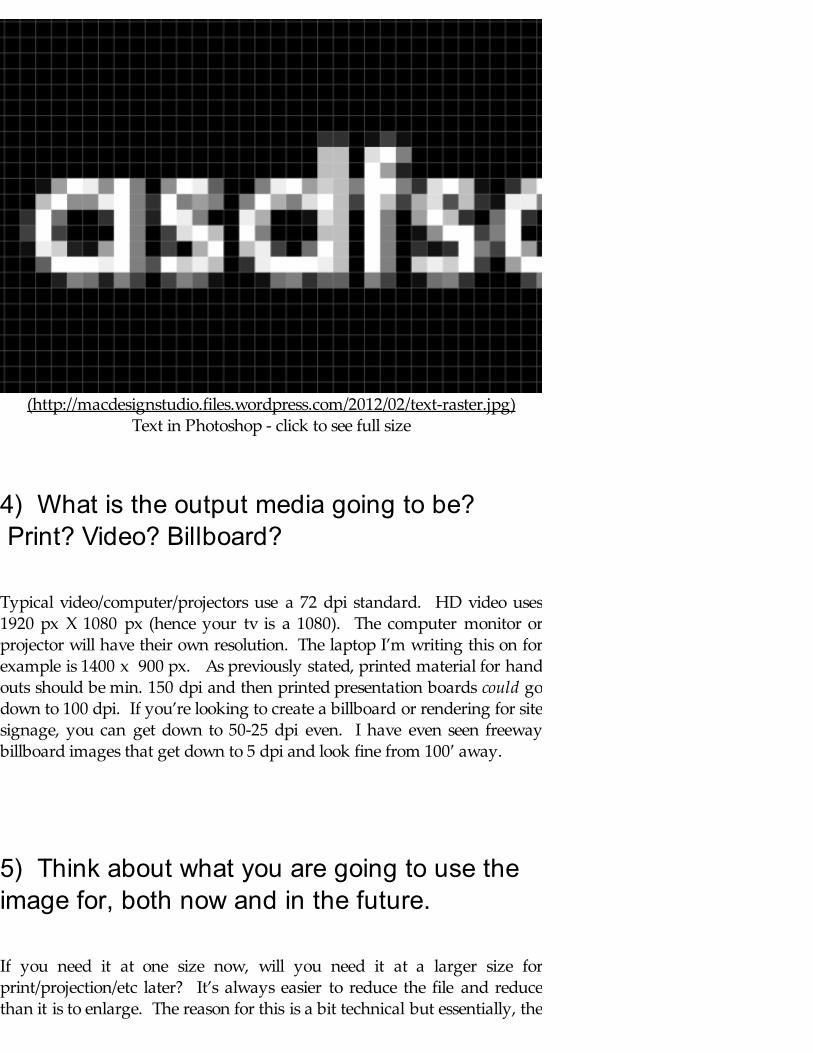
If you need it at one size now, will you need it at a larger size forprint/projection/etc later? It’s always easier to reduce the file and reducethan it is to enlarge. The reason for this is a bit technical but essentially, the

algorithms that a program uses to “guess” what color a pixel needs to bewhen it’s enlarged struggle to execute effectively as they are asked toenlarge and compute more and more pixels. Therefore if you’re askingPhotoshop to increase an image 110%, it might do a decent job. If you askto increase that image 200% however, you’ll notice the image struggles tocreate accurate results. Essentially, the enlargements that you see on NCIS,CSI, etc don’t really exist…sorry to burst your bubble!
Yes, there are ways that you can enlarge an image in Photoshop using“Resample Image” selection but remember, this still is an algorithmcalculating it’s best guess as to what the color of the image should be.
(http://macdesignstudio.files.wordpress.com/2012/02/pixel-divided.jpg)The software will guess what color goes in each red square based on the
color and surrounding colors from the white squares.
Just remember that these algorithms can cause problems if you reduce andimage just to enlarge it again. See what I mean below as I take an image,reduce it and then enlarge it to it’s original size. the problem is that whengoing from small to large, it looks blurry or more pixelated because thecomputer is guessing what the pixel color should be.
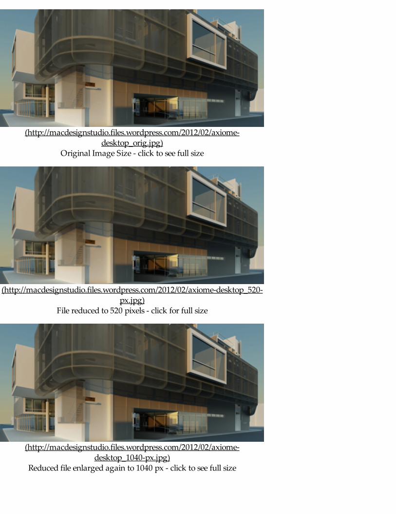
(http://macdesignstudio.files.wordpress.com/2012/02/axiome-desktop_orig.jpg)
Original Image Size - click to see full size
(http://macdesignstudio.files.wordpress.com/2012/02/axiome-desktop_520-px.jpg)
File reduced to 520 pixels - click for full size
(http://macdesignstudio.files.wordpress.com/2012/02/axiome-desktop_1040-px.jpg)
Reduced file enlarged again to 1040 px - click to see full size
Workflow:
Now when you are working about to create a rendering, it starts offby figuring out what size the rendering needs to be. For example, let’s say Ineed a rendering for a hand out. This tells me that I’ll need at minimum150dpi. Go back to our pixel equation from above and we can calculatethat our output should be 1650 pixels (150 dpi X 11 inches) by 2550 pixels(150 dpi X 17 inches). What this also tells me is that with the same outputor image, I can crop the image to fit my 1400×900 pixel laptop screen.
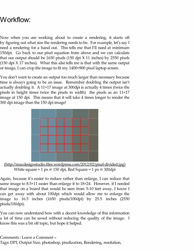
You don’t want to create an output too much larger than necessary becausetime is always going to be an issue. Remember doubling the output isn’tactually doubling it. A 11×17 image at 300dpi is actually 4 times (twice thepixels in height times twice the pixels in width) the pixels as an 11×17image at 150 dpi. This means that it will take 4 times longer to render the300 dpi image than the 150 dpi image!
(http://macdesignstudio.files.wordpress.com/2012/02/pixel-divided.jpg)White square = 1 px @ 150 dpi, Red Square = 1 px @ 300dpi
Again, because it’s easier to reduce rather than enlarge, I can reduce thatsame image to 8.5×11 easier than enlarge it to 18×24. However, if I neededthat image on a board that would be seen from 5-10 feet away, I know Ican get away with about 100dpi which would allow me to enlarge theimage to 16.5 inches (1650 pixels/100dpi) by 25.5 inches (2550pixels/100dpi).
You can now understand how with a decent knowledge of this informationa lot of time can be saved without reducing the quality of the image. Iknow this was a bit off topic, but hope it helped.
Comments : Leave a Comment » Tags: DPI, Output Size, photoshop, pixelization, Rendering, resolution,
Tutorials Categories : Rendering
Vray Materials Part 5 – Emissive
Ok, so I just finished my Architectural Registration Exam study session, mywife is out for a while, and I’ve got a few hours before I’m meeting my sisterand her boyfriend for dinner, (for those keeping track of my day)…let’s seeif we can finish up the last material layer…Emissive Materials.
Emissive Layer:
The emissive layer is the final tutorial on the various layers for Vray. Anemissive layer allows the material to emit light. These types of material canbe used to create effects such as a neon sign, a glowing lamp shade, or atv/computer screen.
I will bring up a few things to keep in mind when using a material that usesan emissive layer.
1. These materials will increase render times, possibly to extreme amounts2. Do not use these materials as the sole lighting for a scene.
Now let’s jump right into it! First we’ll create a new material (which I’llcleverly name “Emissive Material”). There are a lot less parameters thanthe previous two layers, and luckily, they are all fairly straight forward. First I’ll render the scene that I’ve been using previously with a defaultmaterial.
28 01 2012

(http://macdesignstudio.files.wordpress.com/2012/01/default-material-test-render.jpg)
Now let’s create an emissive layer and look at the default parameters.
(http://macdesignstudio.files.wordpress.com/2012/01/emissive-parameters.jpg)
…and we’ll apply it and render
(http://macdesignstudio.files.wordpress.com/2012/01/emissive-material-

(http://macdesignstudio.files.wordpress.com/2012/01/emissive-material-initial-render.jpg)
Now to better show the emissive quality, I’m going to turn off the lightsand the environmental light, leaving the material as the only thing in thescene emitting light (I know, I know I told you never to do this in Rule 2above, but take a look and you can see why never to do this).
(http://macdesignstudio.files.wordpress.com/2012/01/emissive-material-initial-render-background-and-light-off.jpg)
Notice the “Splotchy-ness” and uneven lighting quality around the objects? That’s because our render settings are fairly low for the amount of lightthat is needed to calculate. Essentially, we need more light or to increaseour light in the scene? The increase of render settings will increase ourrendering time (potentially substantially i.e 10-100 times) As a result, it’ssuggested for best results, let’s use a light in the scene and only use emissivematerials for the glowing that they’re meant for.
(http://macdesignstudio.files.wordpress.com/2012/01/splotchyness.jpg)Notice the Splotchy-ness (Note you may have to view enlarged full scale
image)
For the sake of working correctly, and speed, I’ll turn the lights back onand turn them all down to .125 on the multiplier and then turn theenvironment on and turn it down to .1 on the multiplier. Render again and
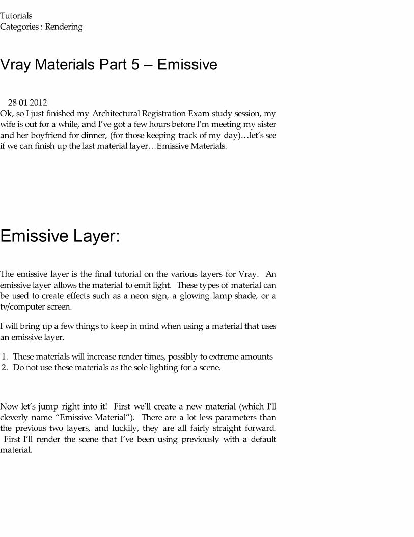
see the splotches have pretty much gone away (there’s still some, but not tothe extent previously. I could tweak settings to make them completelydisappear but don’t have the time nor patience right now, you get the idea).
(http://macdesignstudio.files.wordpress.com/2012/01/emissive-material-initial-render-background-and-light-lower.jpg)
Turning the lights and environmental lighting on, but low multiplier
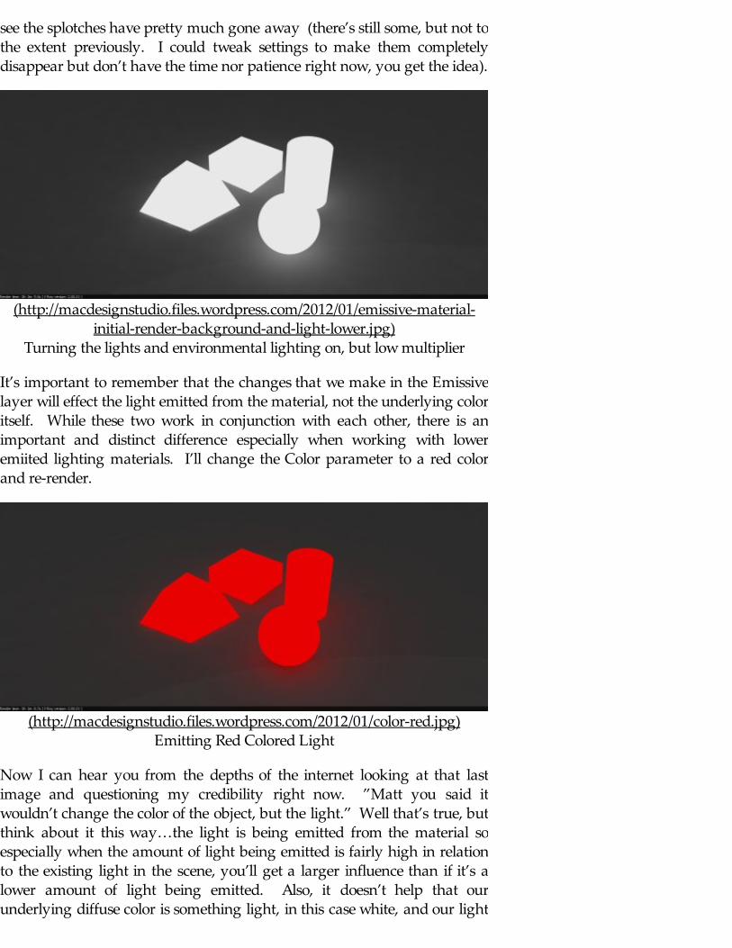
It’s important to remember that the changes that we make in the Emissivelayer will effect the light emitted from the material, not the underlying coloritself. While these two work in conjunction with each other, there is animportant and distinct difference especially when working with loweremiited lighting materials. I’ll change the Color parameter to a red colorand re-render.
(http://macdesignstudio.files.wordpress.com/2012/01/color-red.jpg)Emitting Red Colored Light
Now I can hear you from the depths of the internet looking at that lastimage and questioning my credibility right now. ”Matt you said itwouldn’t change the color of the object, but the light.” Well that’s true, butthink about it this way…the light is being emitted from the material soespecially when the amount of light being emitted is fairly high in relationto the existing light in the scene, you’ll get a larger influence than if it’s alower amount of light being emitted. Also, it doesn’t help that ourunderlying diffuse color is something light, in this case white, and our light

is emitting a very saturated color like this red. So we’ll turn the lightingIntensity down. In this case, I’ll turn it down to 0.1 for a dramaticdifference. Let’s re-render and see what we get.
(http://macdesignstudio.files.wordpress.com/2012/01/color-red-intensity-0_1.jpg)
Turn the Intensity down to 0.1
I can tell, even less confidence in the last few hours you’ve spent listeningand reading through my blog, huh? Well the light being emitted from thematerial certainly is less. The amount of red “glow” that we were getting isnon-existent (0.1 was intentionally used as it’s WAY too low). There’s onelast parameter in the emissive layer that we still need to talk about. The“Transparency” parameter! This one is what controls the transparency ofthe light emitted from the material. You have no reason to trust me, solet’s test it out together. First thing first, I’ll change the diffuse color tosomething obnoxious (cyan usually does the trick), ensuring thatmy transparency map color is set to 100% black.
(http://macdesignstudio.files.wordpress.com/2012/01/change-diffuse-color.jpg)
Change diffuse color
Now I’ll set the Emissive transparancy to Light Grey (230-230-230) andincrease the Intensity back to .5 and re-render.
(http://macdesignstudio.files.wordpress.com/2012/01/cyan-diffuse-and-red-light.jpg)
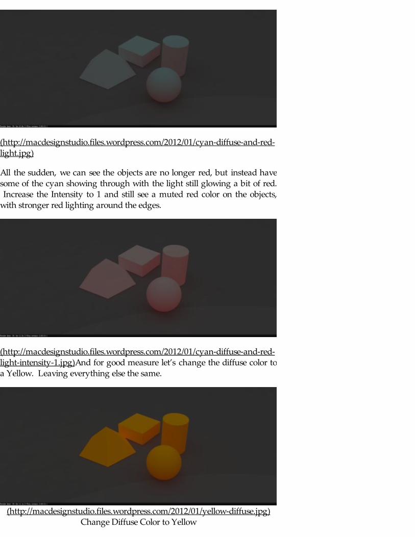
All the sudden, we can see the objects are no longer red, but instead havesome of the cyan showing through with the light still glowing a bit of red. Increase the Intensity to 1 and still see a muted red color on the objects,with stronger red lighting around the edges.
(http://macdesignstudio.files.wordpress.com/2012/01/cyan-diffuse-and-red-light-intensity-1.jpg)And for good measure let’s change the diffuse color toa Yellow. Leaving everything else the same.
(http://macdesignstudio.files.wordpress.com/2012/01/yellow-diffuse.jpg)Change Diffuse Color to Yellow
You’ll notice there is a lot that affects the output color, the color of the light,the transparency of the light, the intensity of the light and underlyingdiffuse color. The relationship of color values and saturation between thediffuse and light color also has an impact on the output as you can see.
When, Where, and How to useEmissive Materials
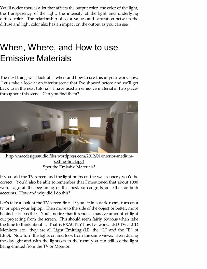
The next thing we’ll look at is when and how to use this in your work flow. Let’s take a look at an interior scene that I’ve showed before and we’ll getback to in the next tutorial. I have used an emissive material in two placesthroughout this scene. Can you find them?
(http://macdesignstudio.files.wordpress.com/2012/01/interior-medium-setting-final.jpg)
Spot the Emissive Materials?
If you said the TV screen and the light bulbs on the wall sconces, you’d becorrect. You’d also be able to remember that I mentioned that about 1000words ago at the beginning of this post, so congrats on either or bothaccounts. How and why did I do this?
Let’s take a look at the TV screen first. If you sit in a dark room, turn on atv, or open your laptop. Then move to the side of the object or better, movebehind it if possible. You’ll notice that it sends a massive amount of lightout projecting from the screen. This should seem fairly obvious when takethe time to think about it. That is EXACTLY how tvs work, LED TVs, LCDMonitors, etc. they are all Light Emitting (I.E. the “L” and the “E” ofLED). Now turn the lights on and look from the same views. Even duringthe daylight and with the lights on in the room you can still see the lightbeing emitted from the TV or Monitor.
With that being said, let’s look at how to make that material. First thing I
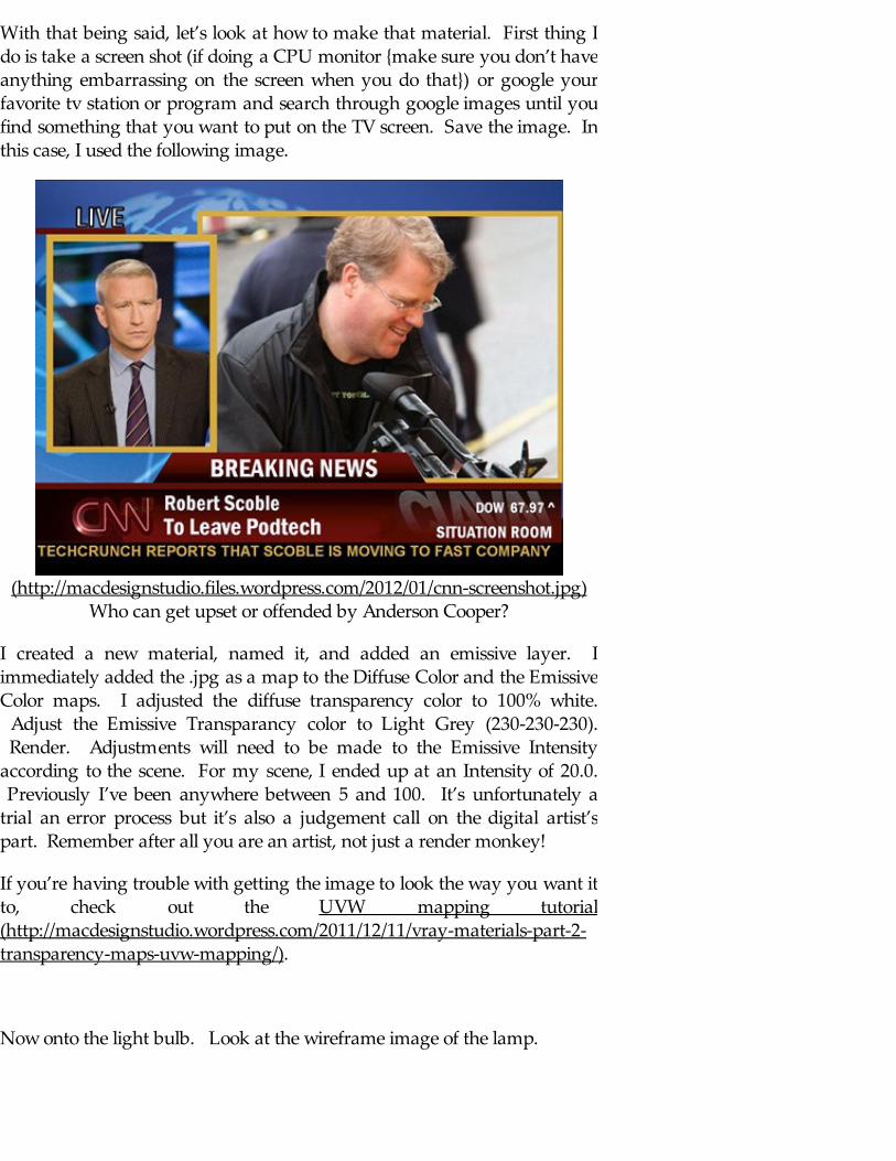
With that being said, let’s look at how to make that material. First thing Ido is take a screen shot (if doing a CPU monitor {make sure you don’t haveanything embarrassing on the screen when you do that}) or google yourfavorite tv station or program and search through google images until youfind something that you want to put on the TV screen. Save the image. Inthis case, I used the following image.
(http://macdesignstudio.files.wordpress.com/2012/01/cnn-screenshot.jpg)Who can get upset or offended by Anderson Cooper?
I created a new material, named it, and added an emissive layer. Iimmediately added the .jpg as a map to the Diffuse Color and the EmissiveColor maps. I adjusted the diffuse transparency color to 100% white. Adjust the Emissive Transparancy color to Light Grey (230-230-230). Render. Adjustments will need to be made to the Emissive Intensityaccording to the scene. For my scene, I ended up at an Intensity of 20.0. Previously I’ve been anywhere between 5 and 100. It’s unfortunately atrial an error process but it’s also a judgement call on the digital artist’spart. Remember after all you are an artist, not just a render monkey!
If you’re having trouble with getting the image to look the way you want itto, check out the UVW mapping tutorial(http://macdesignstudio.wordpress.com/2011/12/11/vray-materials-part-2-transparency-maps-uvw-mapping/).
Now onto the light bulb. Look at the wireframe image of the lamp.

(http://macdesignstudio.files.wordpress.com/2012/01/lamp.jpg)Wireframe of Lamp - Notice Rectangular light
As you can see, I have a rectangular light (the golden colored rectangle)that fits inside the lamp. Because I want the light to go both up and down,I simple click on the check box that makes this light double sided. See theLighting Tutorial(http://macdesignstudio.wordpress.com/2011/04/28/introduction-to-vray-lighting/) for more info) Because I wanted the lamp shade to be somethingsemi-transparent (a linen in this case) I knew that you would see the actuallight bulb and thus wanted to give it an emissive material to give the effectof slowing through the linen. However, (back to rule #2, I didn’t use theemissive material as the light source to light the scene, hence therectangular light). I then created a new emissive material that I applied tothe light bulb. When I got my linen set the way I wanted to, I was able tosee the glow from the bulb through the translucent shade. To adjust thecolor of your light to the actual color temperature of your particular light,
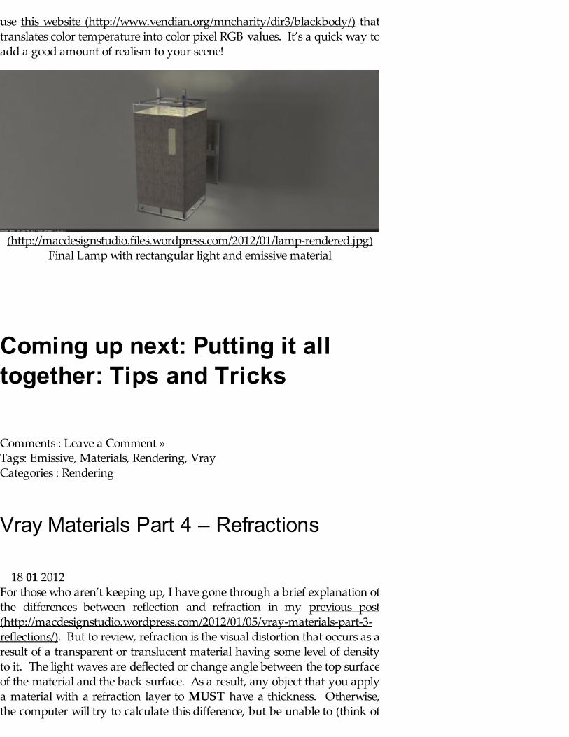
use this website (http://www.vendian.org/mncharity/dir3/blackbody/) thattranslates color temperature into color pixel RGB values. It’s a quick way toadd a good amount of realism to your scene!
(http://macdesignstudio.files.wordpress.com/2012/01/lamp-rendered.jpg)Final Lamp with rectangular light and emissive material
Coming up next: Putting it alltogether: Tips and Tricks
Comments : Leave a Comment » Tags: Emissive, Materials, Rendering, Vray Categories : Rendering
Vray Materials Part 4 – Refractions
For those who aren’t keeping up, I have gone through a brief explanation ofthe differences between reflection and refraction in my previous post(http://macdesignstudio.wordpress.com/2012/01/05/vray-materials-part-3-reflections/). But to review, refraction is the visual distortion that occurs as aresult of a transparent or translucent material having some level of densityto it. The light waves are deflected or change angle between the top surfaceof the material and the back surface. As a result, any object that you applya material with a refraction layer to MUST have a thickness. Otherwise,the computer will try to calculate this difference, but be unable to (think of
18 01 2012
it as dividing by 0) and freak out, resulting in a black output. As a sidenote, you will notice that adding a reflection layer and/or a refraction layerwill cause an increase in render time because of the increase in computingthe machine is asked to do. It now must not only calculate the lighting andmaterial, but also the way in which the light/materials reflect or refract andwhat will be seen as a result. It’s just something that needs to be kept inmind, especially when working with large scenes, tight deadlines, slowmachines, and impatient clients/bosses.
Refraction:
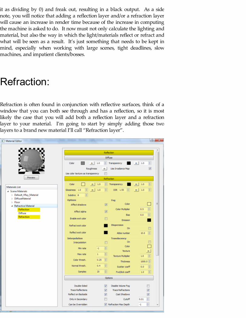
Refraction is often found in conjunction with reflective surfaces, think of awindow that you can both see through and has a reflection, so it is mostlikely the case that you will add both a reflection layer and a refractionlayer to your material. I’m going to start by simply adding those twolayers to a brand new material I’ll call “Refraction layer”.
(http://macdesignstudio.files.wordpress.com/2012/01/reflection_refraction-material-editor.jpg)
When I apply that material to the scene, I find that our initial renderingshows the highly reflective material, but no refraction.
(http://macdesignstudio.files.wordpress.com/2012/01/refraction_initial-rendering.jpg)
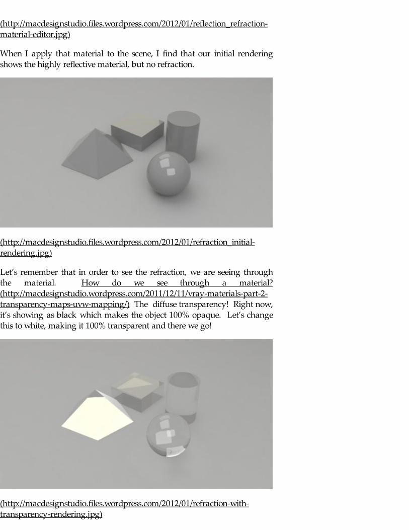
Let’s remember that in order to see the refraction, we are seeing throughthe material. How do we see through a material?(http://macdesignstudio.wordpress.com/2011/12/11/vray-materials-part-2-transparency-maps-uvw-mapping/) The diffuse transparency! Right now,it’s showing as black which makes the object 100% opaque. Let’s changethis to white, making it 100% transparent and there we go!
(http://macdesignstudio.files.wordpress.com/2012/01/refraction-with-transparency-rendering.jpg)

It’s important to make sure that you change the transparency color on thediffuse layer, not on the refraction layer. We want the overall object toappear transparent, not the amount of refraction. I will be sure to explainthis further later in this tutorial. Looking at our rendering we can see thatthese objects, specifically the sphere are beginning to show a bit ofdistortion and look very glass like. To accentuate this, I’m going to changethe floor material to a check board pattern and re-render.
(http://macdesignstudio.files.wordpress.com/2012/01/refraction-with-transparency-rendering_checkered-background.jpg)
With the new rendering we can better see how the materials both reflect thelight (which is why the pyramid to the left is all white…it’s reflecting thedirect light at a harsh angle) and refract the light. Now that we understandwhat these features are and how they work and are applied to materials,let’s look at how to better control the features of the refraction layer.
IOR:
The IOR as it deals with refraction will increase the amount of distortion inthe material as the IOR increases. It’s important to keep in mind that theIOR for refraction and reflection are different, however for the mostaccurate results they should be the same. A few good values to keep inmind according to the Rhino Manual:
Vacuum = 1.0 Air = 1.00029 Alcohol=1.329 Ice=1.309
Water=1.33 Glass=1.517 (I like to use 1.42) Crystal=2.0 Diamond=2.417
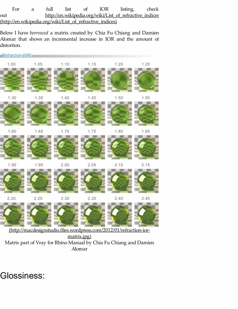
For a full list of IOR listing, checkout http://en.wikipedia.org/wiki/List_of_refractive_indices(http://en.wikipedia.org/wiki/List_of_refractive_indices)
Below I have borrowed a matrix created by Chia Fu Chiang and DamienAlomar that shows an incremental increase in IOR and the amount ofdistortion.
(http://macdesignstudio.files.wordpress.com/2012/01/refraction-ior-matrix.jpg)
Matrix part of Vray for Rhino Manual by Chia Fu Chiang and DamienAlomar
Glossiness:
Similarly to the IOR, Glossiness is a parameter in both Reflective and

Similarly to the IOR, Glossiness is a parameter in both Reflective andRefractive layers. The difference between the two is that the ReflectiveGlossiness deals strictly with the amount of reflection dealing with thesurface. The refraction glossiness will have an effect on what happendinside the material, therefore having and effect on the transparency. It’sthrough this parameter that the materials can appear frosted. Therefraction will become more blurry based as the Refraction Glossinessdecreases.
Again, below I’m borrowing a matrix from the Vray for Rhino Manual. Thematrix below sets the IOR at 1.55 but changes the Glossiness. It’s importantto see that the transparency changes rapidly between a glossiness of 0.80 to.75.
(http://macdesignstudio.files.wordpress.com/2012/01/refraction-glossiness-matrix.jpg)
Matrix part of Vray for Rhino Manual by Chia Fu Chiang and DamienAlomar

Fog
The Fog parameter allows you to give a refractive surface a tint of color. This can be useful when attempting to create a tinted glass, blue, green orotherwise.
I have added a color (63-191-191) to the fog, see settings below:
(http://macdesignstudio.files.wordpress.com/2012/01/fog-scene-setting.jpg)
Notice how the color is added to the material. The strength of the colordepends on both the thickness of the material and the fog color multiplier.
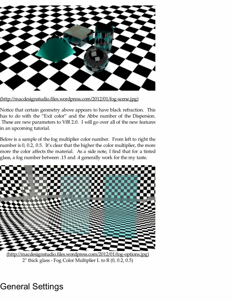
(http://macdesignstudio.files.wordpress.com/2012/01/fog-scene.jpg)
Notice that certain geometry above appears to have black refraction. Thishas to do with the “Exit color” and the Abbe number of the Dispersion. These are new parameters to VfR 2.0. I will go over all of the new featuresin an upcoming tutorial.
Below is a sample of the fog multiplier color number. From left to right thenumber is 0, 0.2, 0.5. It’s clear that the higher the color multiplier, the moremore the color affects the material. As a side note, I find that for a tintedglass, a fog number between .15 and .4 generally work for the my taste.
(http://macdesignstudio.files.wordpress.com/2012/01/fog-options.jpg)2" thick glass - Fog Color Multiplier L to R (0, 0.2, 0.5)
General Settings
Options
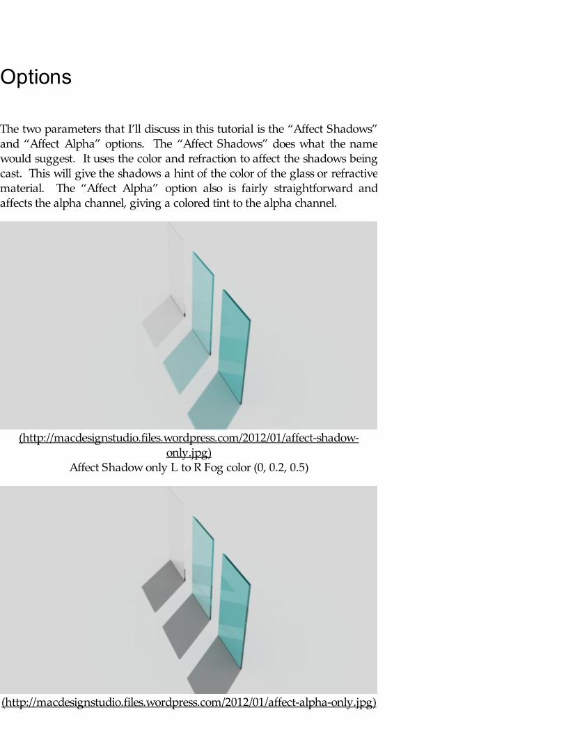
The two parameters that I’ll discuss in this tutorial is the “Affect Shadows”and “Affect Alpha” options. The “Affect Shadows” does what the namewould suggest. It uses the color and refraction to affect the shadows beingcast. This will give the shadows a hint of the color of the glass or refractivematerial. The “Affect Alpha” option also is fairly straightforward andaffects the alpha channel, giving a colored tint to the alpha channel.
(http://macdesignstudio.files.wordpress.com/2012/01/affect-shadow-only.jpg)
Affect Shadow only L to R Fog color (0, 0.2, 0.5)
(http://macdesignstudio.files.wordpress.com/2012/01/affect-alpha-only.jpg)

Affect Alpha only L to R Fog color (0, 0.2, 0.5)
(http://macdesignstudio.files.wordpress.com/2012/01/affect-alpha-and-shadow.jpg)
Affect Alpha + Shadow L to R Fog color (0, 0.2, 0.5)
Translucency
Again, because I feel the need to be 100% honest to you, my loyal readers, Imust disclose to you that I have a tough time with the Translucencyparameters (and considering I haven’t been able to find anything onlinethat really makes sense, I feel that you don’t get it either). I think that Istruggle primarily because the numbers mean absolutely nothing and asfar as I can tell just are a value relative to each other. However, in an effortto gain your faith back, I will tell you know I do know or have figured outfor Translucency. This type of material is often referred to as Sub-surfaceScattering material (SSS)
Translucency will have an effect on the material, allowing light to penetratethrough the material based on the thickness of the material at a given point. As a result, this is a very helpful material type to use for wax, skin, milk,plastic, etc.
1) Always change the IOR to 1.0
2) Change the transparency away from pure white. Try value 80-150.
3) Uncheck Double sided material under “Options”
4) Lower the Refraction Glossiness to something under 1.0
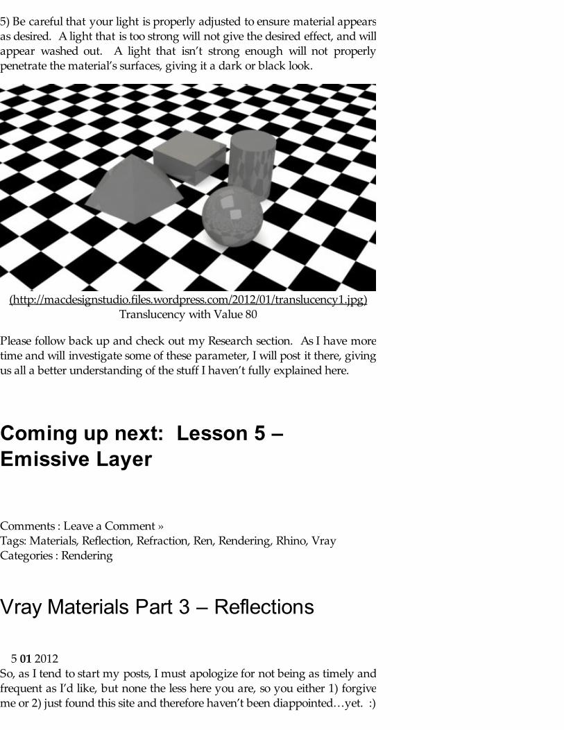
5) Be careful that your light is properly adjusted to ensure material appearsas desired. A light that is too strong will not give the desired effect, and willappear washed out. A light that isn’t strong enough will not properlypenetrate the material’s surfaces, giving it a dark or black look.
(http://macdesignstudio.files.wordpress.com/2012/01/translucency1.jpg)Translucency with Value 80
Please follow back up and check out my Research section. As I have moretime and will investigate some of these parameter, I will post it there, givingus all a better understanding of the stuff I haven’t fully explained here.
Coming up next: Lesson 5 –Emissive Layer
Comments : Leave a Comment » Tags: Materials, Reflection, Refraction, Ren, Rendering, Rhino, Vray Categories : Rendering
Vray Materials Part 3 – Reflections
So, as I tend to start my posts, I must apologize for not being as timely andfrequent as I’d like, but none the less here you are, so you either 1) forgiveme or 2) just found this site and therefore haven’t been diappointed…yet. :)
5 01 2012
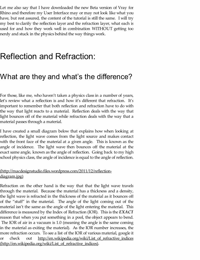
Let me also say that I have downloaded the new Beta version of Vray forRhino and therefore my User Interface may or may not look like what youhave, but rest assured, the content of the tutorial is still the same. I will trymy best to clarify the reflection layer and the refraction layer, what each isused for and how they work well in combination WITHOUT getting toonerdy and stuck in the physics behind the way things work.
Reflection and Refraction:
What are they and what’s the difference?
For those, like me, who haven’t taken a physics class in a number of years,let’s review what a reflection is and how it’s different that refraction. It’simportant to remember that both reflection and refraction have to do withthe way that light reacts to a material. Reflection deals with the way thatlight bounces off of the material while refraction deals with the way that amaterial passes through a material.
I have created a small diagram below that explains how when looking atreflection, the light wave comes from the light source and makes contactwith the front face of the material at a given angle. This is known as theangle of incidence. The light wave then bounces off the material at theexact same angle, known as the angle of reflection. Going back to my highschool physics class, the angle of incidence is equal to the angle of reflection.
(http://macdesignstudio.files.wordpress.com/2011/12/reflection-diagram.jpg)
Refraction on the other hand is the way that that the light wave travelsthrough the material. Because the material has a thickness and a density,the light wave is refracted in the thickness of the material as it bounces offof the “stuff” in the material. The angle of the light coming out of thematerial isn’t the same as the angle of the light entering the material. Thisdifference is measured by the Index of Refraction (IOR). This is the EXACTreason that when you put something in a pool, the object appears to bend. The IOR of air in a vacuum is 1.0 (meaning the angle is the same comingin the material as exiting the material). As the IOR number increases, themore refraction occurs. To see a list of the IOR of various material, google itor check out http://en.wikipedia.org/wiki/List_of_refractive_indices(http://en.wikipedia.org/wiki/List_of_refractive_indices).

(http://macdesignstudio.files.wordpress.com/2011/12/refraction-diagram.jpg)
Reflection Layer:
The reflection layer controls the amount that a material reflects thesurround scene. This goes anywhere from a mirror like surface to a muchmore subtle reflection off of a hand railing, glass on a table, or piece ofplastic. it is important to think of the reflection layer as dealing with simplythe REFLECTIONS of that material, regardless of the transparency, etc.
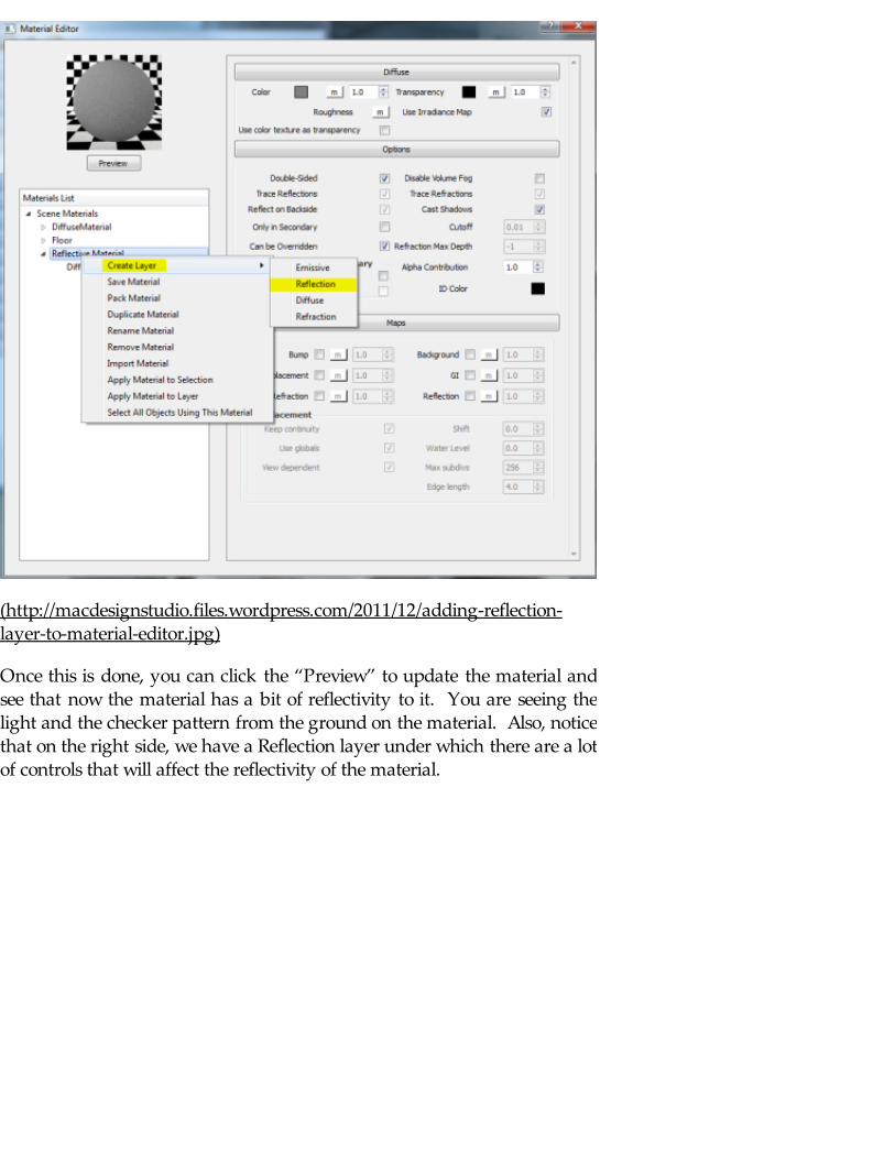
To add a reflection to your material you will have to add a reflection layerto your material. This will allow you to control many of the properties ofthe material’s reflection. To do this, create a new material and rename itappropriately. Then right click the name of the material and a new pop-upmenu will give you many options. You want to select the “Create Layer”and then “Reflection”. When this is done, you will see under the materialname you now have both a reflection layer and a diffuse layer.
(http://macdesignstudio.files.wordpress.com/2011/12/adding-reflection-layer-to-material-editor.jpg)
Once this is done, you can click the “Preview” to update the material andsee that now the material has a bit of reflectivity to it. You are seeing thelight and the checker pattern from the ground on the material. Also, noticethat on the right side, we have a Reflection layer under which there are a lotof controls that will affect the reflectivity of the material.

(http://macdesignstudio.files.wordpress.com/2011/12/reflection-layer_material-editor.jpg)
Applying this reflective material to the existing scene, we can give it a quickrender to use as a baseline for some of the upcoming changes we will make. Below you will see my initial render:
(http://macdesignstudio.files.wordpress.com/2011/12/initial-reflection-rendering.jpg)
Reflection Map:
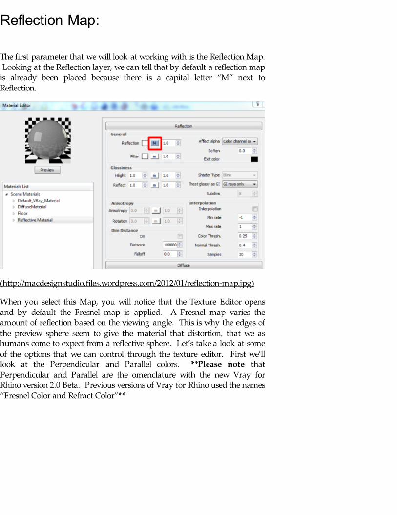
The first parameter that we will look at working with is the Reflection Map. Looking at the Reflection layer, we can tell that by default a reflection mapis already been placed because there is a capital letter “M” next toReflection.
(http://macdesignstudio.files.wordpress.com/2012/01/reflection-map.jpg)
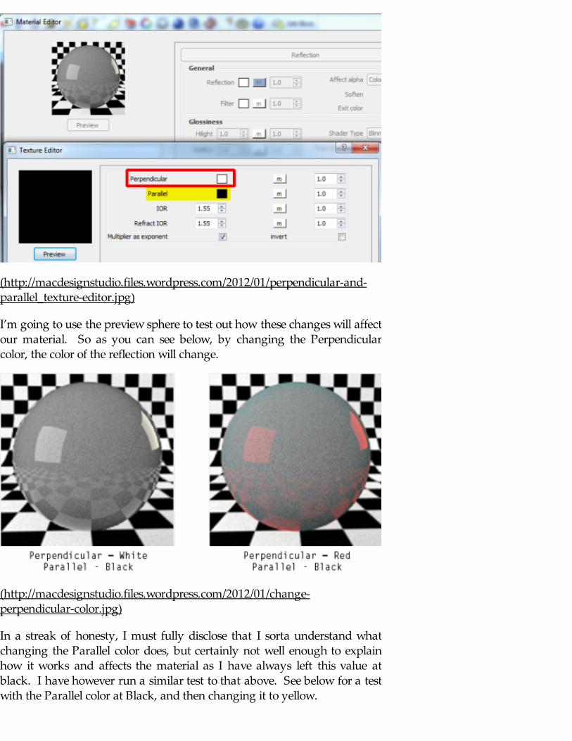
When you select this Map, you will notice that the Texture Editor opensand by default the Fresnel map is applied. A Fresnel map varies theamount of reflection based on the viewing angle. This is why the edges ofthe preview sphere seem to give the material that distortion, that we ashumans come to expect from a reflective sphere. Let’s take a look at someof the options that we can control through the texture editor. First we’lllook at the Perpendicular and Parallel colors. **Please note thatPerpendicular and Parallel are the omenclature with the new Vray forRhino version 2.0 Beta. Previous versions of Vray for Rhino used the names“Fresnel Color and Refract Color”**
(http://macdesignstudio.files.wordpress.com/2012/01/perpendicular-and-parallel_texture-editor.jpg)
I’m going to use the preview sphere to test out how these changes will affectour material. So as you can see below, by changing the Perpendicularcolor, the color of the reflection will change.
(http://macdesignstudio.files.wordpress.com/2012/01/change-perpendicular-color.jpg)
In a streak of honesty, I must fully disclose that I sorta understand whatchanging the Parallel color does, but certainly not well enough to explainhow it works and affects the material as I have always left this value atblack. I have however run a similar test to that above. See below for a testwith the Parallel color at Black, and then changing it to yellow.

(http://macdesignstudio.files.wordpress.com/2012/01/change-parallel-color.jpg)
Now that we understand what these parameters do, we can adjust themwhen we are looking to get away from the mirror/chrome look andattempting to give a bit more realism to our scene by adding color to ourreflections. The last parameter that we will explore under the Fresnel mapis the IOR. This number determines how reflective a material is. To betechnical (I know I tried to avoid being all physics nerd, but bear with me)As the Fresnel IOR (Index of Refaction) gets lower, the larger an angle isneeded to have the material reflect. A higher IOR means that a smallerangle is needed to create a reflection. What’s that mean to you?? Take alook back at our previous reflection diagram: A higher Fresnel IOR meansthat at a slight angle, I can see reflections. At a lower IOR at the sameangle, I might not see the material as reflective. As previously mentioned,you can find many websites that give a close approximation for the IOR ofvarious materials. Lets’ try manipulating this parameter to allow someexperimentation using our previous scene:
(http://macdesignstudio.files.wordpress.com/2012/01/fresnel-ior-tests.jpg)
As an aside, I know I didn’t tell you what the Refract IOR does here, but if I

As an aside, I know I didn’t tell you what the Refract IOR does here, but if Inever change the Parallel (Refract) Color, you really think I have thefoggiest clue what the Refract IOR does here??
Filter Color:
Very quickly and simply, the filter color changes the color of the overallreflection. If I want all my reflections to appear red, I’ll change the filtercolor from white to red. The amount that this color is taken on in thereflection is directly correlated to the strength of the reflections. This issimilar to how the Perpendicular Color works, but see below to see thedifference between the two.
(http://macdesignstudio.files.wordpress.com/2012/01/perpendicular-vs-filter-color.jpg)
Reflection Glossiness:
The Glossiness parameters allow you to control how the reflections look asthey are being reflected off of a material. Think about some of the highlyreflective materials that you have run into over the last 24 hours. You wokeup this morning and presumably brushed your teeth, spitting yourtoothpaste into a highly reflective porcelain sink, looking up in the highlyreflective mirror to ensure your hair was perfectly in place before grabbingyour stainless steel travel coffee cup before you headed out the door. Before
you made it out the door to work this morning you have already dealt withthree very different levels of reflectivity that couldn’t be established with thepreviously discussed parameters alone.
The sink is a material that dissipates the reflection a bit because of thenatural occurring scratches, dents, etc in the material. The mirror givesseemingly accurate highly glossy reflections that nearly mimic the actualobjects.
The stainless steel travel mug is a good example because it really dependson the type of mug that you have. Mine for example is a brushed stainless,which means that it is much less glossy and doesn’t give the clear andhighly articulate reflections that my wife’s, whose is closer to a mirrorfinish, does.
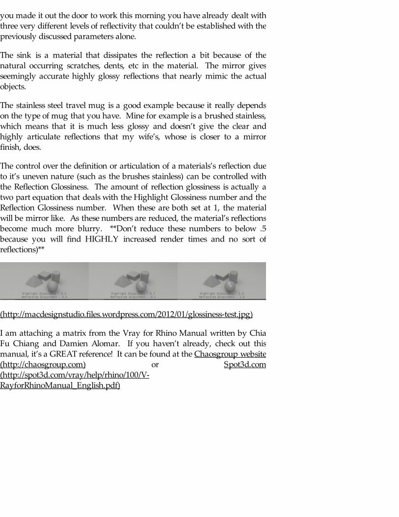
The control over the definition or articulation of a materials’s reflection dueto it’s uneven nature (such as the brushes stainless) can be controlled withthe Reflection Glossiness. The amount of reflection glossiness is actually atwo part equation that deals with the Highlight Glossiness number and theReflection Glossiness number. When these are both set at 1, the materialwill be mirror like. As these numbers are reduced, the material’s reflectionsbecome much more blurry. **Don’t reduce these numbers to below .5because you will find HIGHLY increased render times and no sort ofreflections)**
(http://macdesignstudio.files.wordpress.com/2012/01/glossiness-test.jpg)
I am attaching a matrix from the Vray for Rhino Manual written by ChiaFu Chiang and Damien Alomar. If you haven’t already, check out thismanual, it’s a GREAT reference! It can be found at the Chaosgroup website(http://chaosgroup.com) or Spot3d.com(http://spot3d.com/vray/help/rhino/100/V-RayforRhinoManual_English.pdf)

(http://macdesignstudio.files.wordpress.com/2012/01/fresnel-ior_reflection-glossiness-matrix.jpg)
Matrix part of Vray for Rhino Manual by Chia Fu Chiang and DamienAlomar
Coming up next: Lesson 4 –Refraction Layer
Comments : 2 Comments » Tags: Materials, Reflection, Rendering, Vray Categories : Rendering
Vray Materials – Part 2: TransparencyMaps + UVW Mapping
Well, I’m back from the LEED studying abyss. So I figure it’s about timeto get back to helping those of you following me with more Vray materialtutorials.
11 12 2011
Transparency Maps:
In the previous tutorial, I have shown how to create a diffuse material andeven how to add a jpeg to create a brick material. Let’s take that a stepfurther to look at how to add a sense of transparency to our materials.
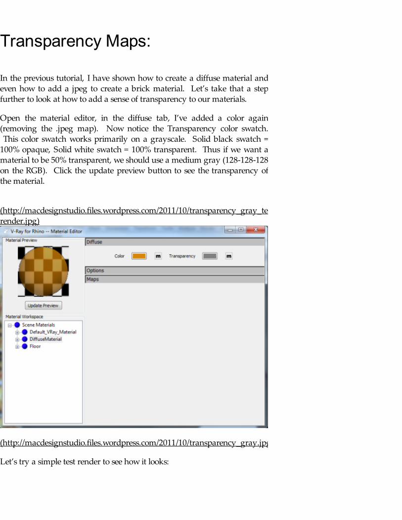
Open the material editor, in the diffuse tab, I’ve added a color again(removing the .jpeg map). Now notice the Transparency color swatch. This color swatch works primarily on a grayscale. Solid black swatch =100% opaque, Solid white swatch = 100% transparent. Thus if we want amaterial to be 50% transparent, we should use a medium gray (128-128-128on the RGB). Click the update preview button to see the transparency ofthe material.
(http://macdesignstudio.files.wordpress.com/2011/10/transparency_gray_test-render.jpg)
(http://macdesignstudio.files.wordpress.com/2011/10/transparency_gray.jpg)
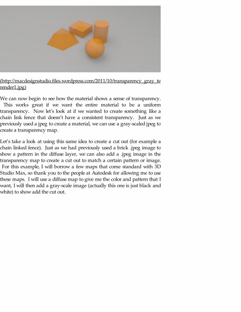
Let’s try a simple test render to see how it looks:
(http://macdesignstudio.files.wordpress.com/2011/10/transparency_gray_test-render1.jpg)
We can now begin to see how the material shows a sense of transparency. This works great if we want the entire material to be a uniformtransparency. Now let’s look at if we wanted to create something like achain link fence that doesn’t have a consistent transparency. Just as wepreviously used a jpeg to create a material, we can use a gray-scaled jpeg tocreate a transparency map.
Let’s take a look at using this same idea to create a cut out (for example achain linked fence). Just as we had previously used a brick .jpeg image toshow a pattern in the diffuse layer, we can also add a .jpeg image in thetransparency map to create a cut out to match a certain pattern or image. For this example, I will borrow a few maps that come standard with 3DStudio Max, so thank you to the people at Autodesk for allowing me to usethese maps. I will use a diffuse map to give me the color and pattern that Iwant, I will then add a gray-scale image (actually this one is just black andwhite) to show add the cut out.

(http://macdesignstudio.files.wordpress.com/2011/12/sitework-site-improvements-fences-gateschain-link.jpg)
This is the image to be used and placed in the Diffuse Layer color map slot.
One that is rendered, you should see an image similar to below:
(http://macdesignstudio.files.wordpress.com/2011/12/chainlink_diffuse.jpg)
In order to change the black background into something transparent thatcan be seen through, we will have to add the image below to theTransparency map under the diffuse layer. Notice the image is black and

white. Just as when we previously used colors only to affect thetransparency, white will be completely transparent, black areas will becompletely opaque and the gray scale will affect the amountof transparency accordingly.
(http://macdesignstudio.files.wordpress.com/2011/12/sitework-site-improvements-fences-gateschain-link-cutout.jpg)
Chainlink cut out image to be placed in the transparency map under thediffuse layer
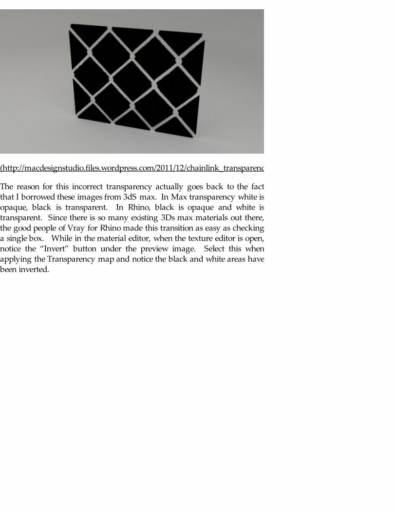
Follow the same methods as previously to add the cut out image below tothe transparency map and we will get the following render. Thetransparency objects are completely opposite of what we want.
(http://macdesignstudio.files.wordpress.com/2011/12/chainlink_transparency_opposite.jpg)
The reason for this incorrect transparency actually goes back to the factthat I borrowed these images from 3dS max. In Max transparency white isopaque, black is transparent. In Rhino, black is opaque and white istransparent. Since there is so many existing 3Ds max materials out there,the good people of Vray for Rhino made this transition as easy as checkinga single box. While in the material editor, when the texture editor is open,notice the “Invert” button under the preview image. Select this whenapplying the Transparency map and notice the black and white areas havebeen inverted.
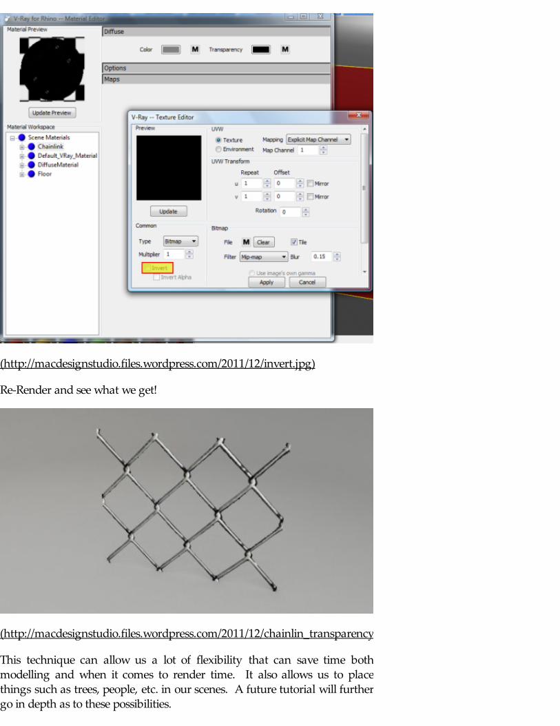
(http://macdesignstudio.files.wordpress.com/2011/12/invert.jpg)
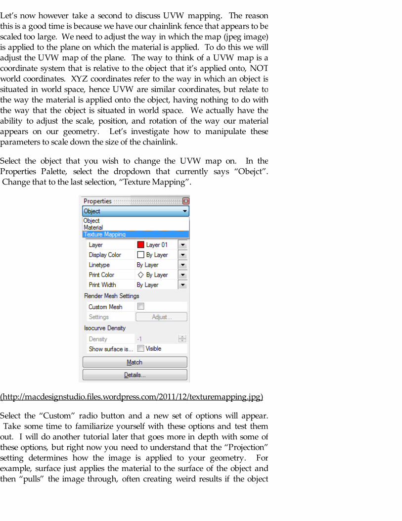
Re-Render and see what we get!
(http://macdesignstudio.files.wordpress.com/2011/12/chainlin_transparency.jpg)
This technique can allow us a lot of flexibility that can save time bothmodelling and when it comes to render time. It also allows us to placethings such as trees, people, etc. in our scenes. A future tutorial will furthergo in depth as to these possibilities.
Let’s now however take a second to discuss UVW mapping. The reasonthis is a good time is because we have our chainlink fence that appears to bescaled too large. We need to adjust the way in which the map (jpeg image)is applied to the plane on which the material is applied. To do this we willadjust the UVW map of the plane. The way to think of a UVW map is acoordinate system that is relative to the object that it’s applied onto, NOTworld coordinates. XYZ coordinates refer to the way in which an object issituated in world space, hence UVW are similar coordinates, but relate tothe way the material is applied onto the object, having nothing to do withthe way that the object is situated in world space. We actually have theability to adjust the scale, position, and rotation of the way our materialappears on our geometry. Let’s investigate how to manipulate theseparameters to scale down the size of the chainlink.
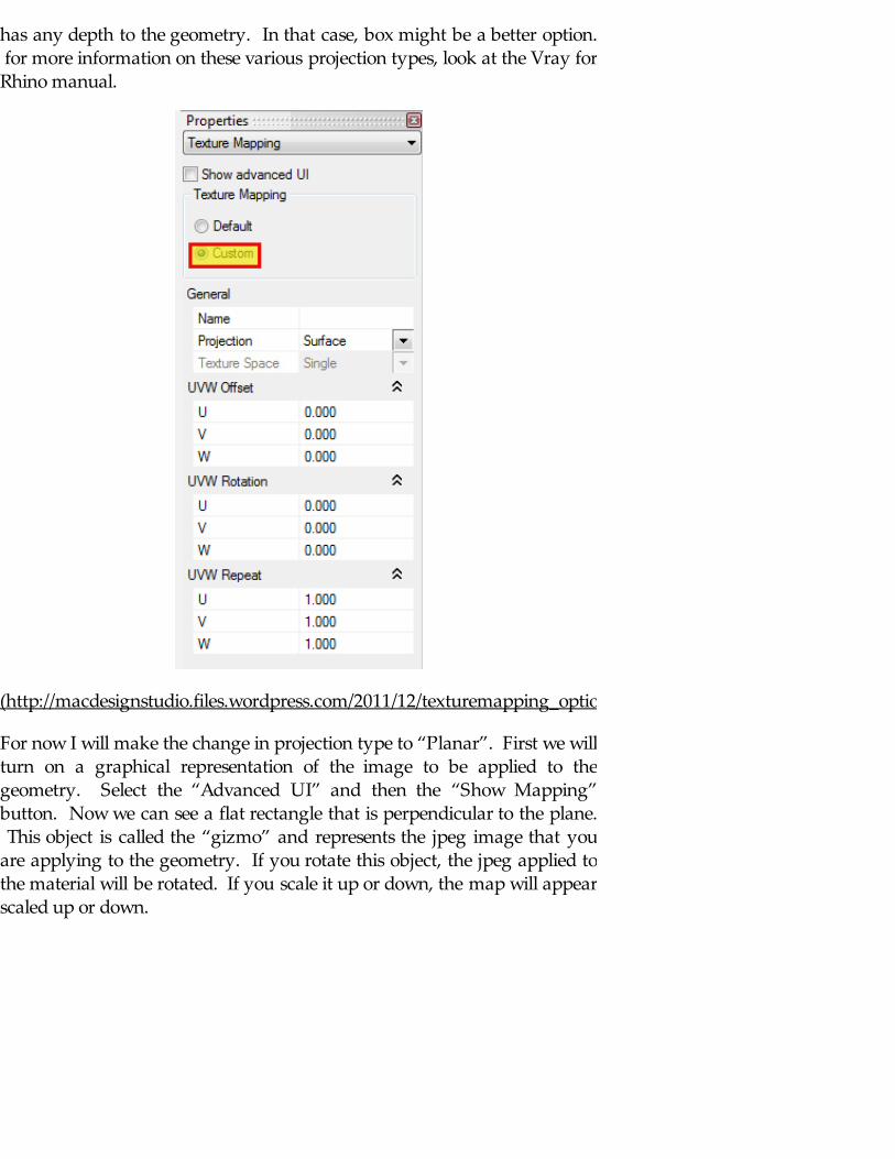
Select the object that you wish to change the UVW map on. In theProperties Palette, select the dropdown that currently says “Obejct”. Change that to the last selection, “Texture Mapping”.
(http://macdesignstudio.files.wordpress.com/2011/12/texturemapping.jpg)
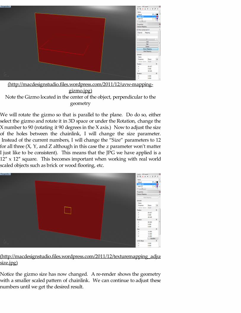
Select the “Custom” radio button and a new set of options will appear. Take some time to familiarize yourself with these options and test themout. I will do another tutorial later that goes more in depth with some ofthese options, but right now you need to understand that the “Projection”setting determines how the image is applied to your geometry. Forexample, surface just applies the material to the surface of the object andthen “pulls” the image through, often creating weird results if the object
has any depth to the geometry. In that case, box might be a better option. for more information on these various projection types, look at the Vray forRhino manual.
(http://macdesignstudio.files.wordpress.com/2011/12/texturemapping_options.jpg)
For now I will make the change in projection type to “Planar”. First we willturn on a graphical representation of the image to be applied to thegeometry. Select the “Advanced UI” and then the “Show Mapping”button. Now we can see a flat rectangle that is perpendicular to the plane. This object is called the “gizmo” and represents the jpeg image that youare applying to the geometry. If you rotate this object, the jpeg applied tothe material will be rotated. If you scale it up or down, the map will appearscaled up or down.
(http://macdesignstudio.files.wordpress.com/2011/12/uvw-mapping-gizmo.jpg)
Note the Gizmo located in the center of the object, perpendicular to thegeometry
We will rotate the gizmo so that is parallel to the plane. Do do so, eitherselect the gizmo and rotate it in 3D space or under the Rotation, change theX number to 90 (rotating it 90 degrees in the X axis.) Now to adjust the sizeof the holes between the chainlink, I will change the size parameter. Instead of the current numbers, I will change the “Size” parameters to 12for all three (X, Y, and Z although in this case the z parameter won’t matterI just like to be consistent). This means that the JPG we have applied is a12″ x 12″ square. This becomes important when working with real worldscaled objects such as brick or wood flooring, etc.
(http://macdesignstudio.files.wordpress.com/2011/12/texturemapping_adjusted-size.jpg)
Notice the gizmo size has now changed. A re-render shows the geometrywith a smaller scaled pattern of chainlink. We can continue to adjust thesenumbers until we get the desired result.
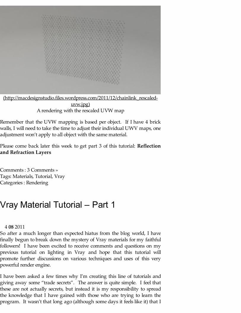
(http://macdesignstudio.files.wordpress.com/2011/12/chainlink_rescaled-uvw.jpg)
A rendering with the rescaled UVW map
Remember that the UVW mapping is based per object. If I have 4 brickwalls, I will need to take the time to adjust their individual UWV maps, oneadjustment won’t apply to all object with the same material.
Please come back later this week to get part 3 of this tutorial: Reflectionand Refraction Layers
Comments : 3 Comments » Tags: Materials, Tutorial, Vray Categories : Rendering
Vray Material Tutorial – Part 1
So after a much longer than expected hiatus from the blog world, I havefinally begun to break down the mystery of Vray materials for my faithfulfollowers! I have been excited to receive comments and questions on myprevious tutorial on lighting in Vray and hope that this tutorial willpromote further discussions on various techniques and uses of this verypowerful render engine.
I have been asked a few times why I’m creating this line of tutorials andgiving away some “trade secrets”. The answer is quite simple. I feel thatthese are not actually secrets, but instead it is my responsibility to spreadthe knowledge that I have gained with those who are trying to learn theprogram. It wasn’t that long ago (although some days it feels like it) that I
4 08 2011

was new to the digital visualization industry. Without the help of others, Iwouldn’t be where I am today, nor would I have the skill set that I feelfortunate enough to share with others. My honest hope is that sharing myknoweldge is as influential on others as some have been on me.
And now on to the learning!
Introduction:
For the purposes of this tutorial, I am using a very simplistic scene thatutilizes the Vray Express Scene as a background. This can be found if youhave the “Vray Express” toolbar installed under the “Vray Express. VrayExpress Studio Scenes” button. To get to this, right click on any emptyportion of the tool bar area and scroll to the proper check box and ensurethat it’s checked. A ewtoolbar should pop up and you can select theappropriate size studio scene for this tutorial. This is a handy way to createproper lighting and ground/background plane for your scene.
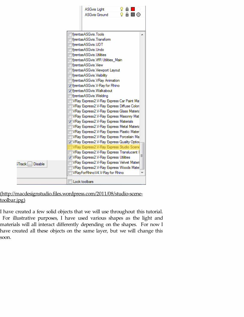
(http://macdesignstudio.files.wordpress.com/2011/08/studio-scene-toolbar.jpg)
I have created a few solid objects that we will use throughout this tutorial. For illustrative purposes, I have used various shapes as the light andmaterials will all interact differently depending on the shapes. For now Ihave created all these objects on the same layer, but we will change thissoon.
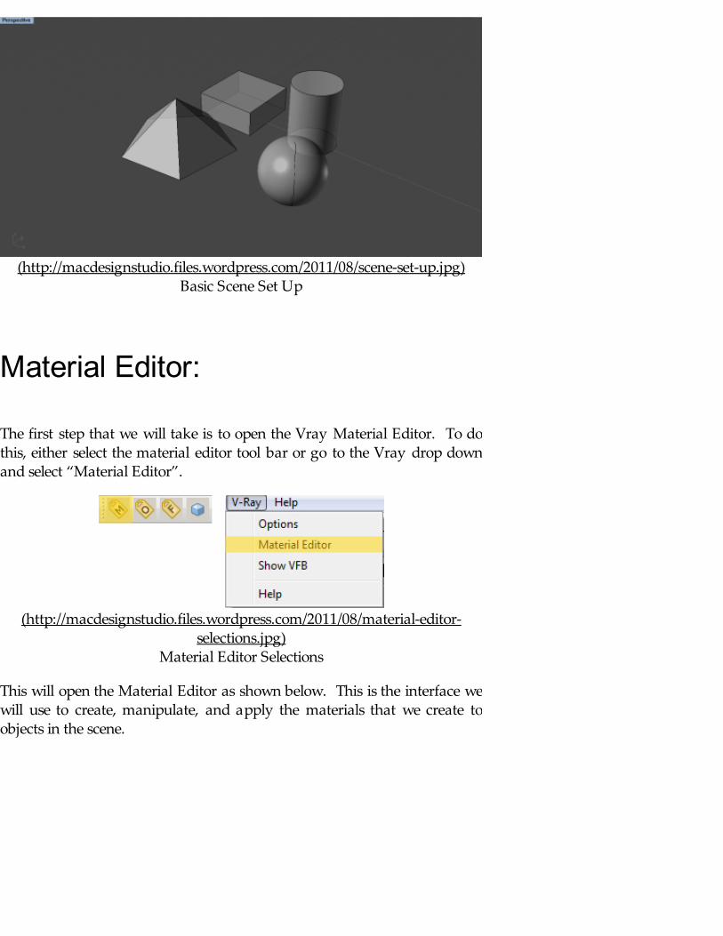
(http://macdesignstudio.files.wordpress.com/2011/08/scene-set-up.jpg)Basic Scene Set Up
Material Editor:
The first step that we will take is to open the Vray Material Editor. To dothis, either select the material editor tool bar or go to the Vray drop downand select “Material Editor”.
(http://macdesignstudio.files.wordpress.com/2011/08/material-editor-selections.jpg)
Material Editor Selections
This will open the Material Editor as shown below. This is the interface wewill use to create, manipulate, and apply the materials that we create toobjects in the scene.
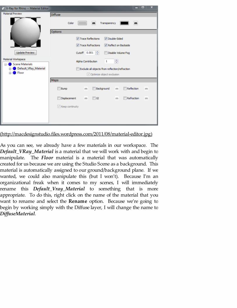
(http://macdesignstudio.files.wordpress.com/2011/08/material-editor.jpg)
As you can see, we already have a few materials in our workspace. TheDefault_VRay_Material is a material that we will work with and begin tomanipulate. The Floor material is a material that was automaticallycreated for us because we are using the Studio Scene as a background. Thismaterial is automatically assigned to our ground/background plane. If wewanted, we could also manipulate this (but I won’t). Because I’m anorganizational freak when it comes to my scenes, I will immediatelyrename this Default_Vray_Material to something that is moreappropriate. To do this, right click on the name of the material that youwant to rename and select the Rename option. Because we’re going tobegin by working simply with the Diffuse layer, I will change the name toDiffuseMaterial.
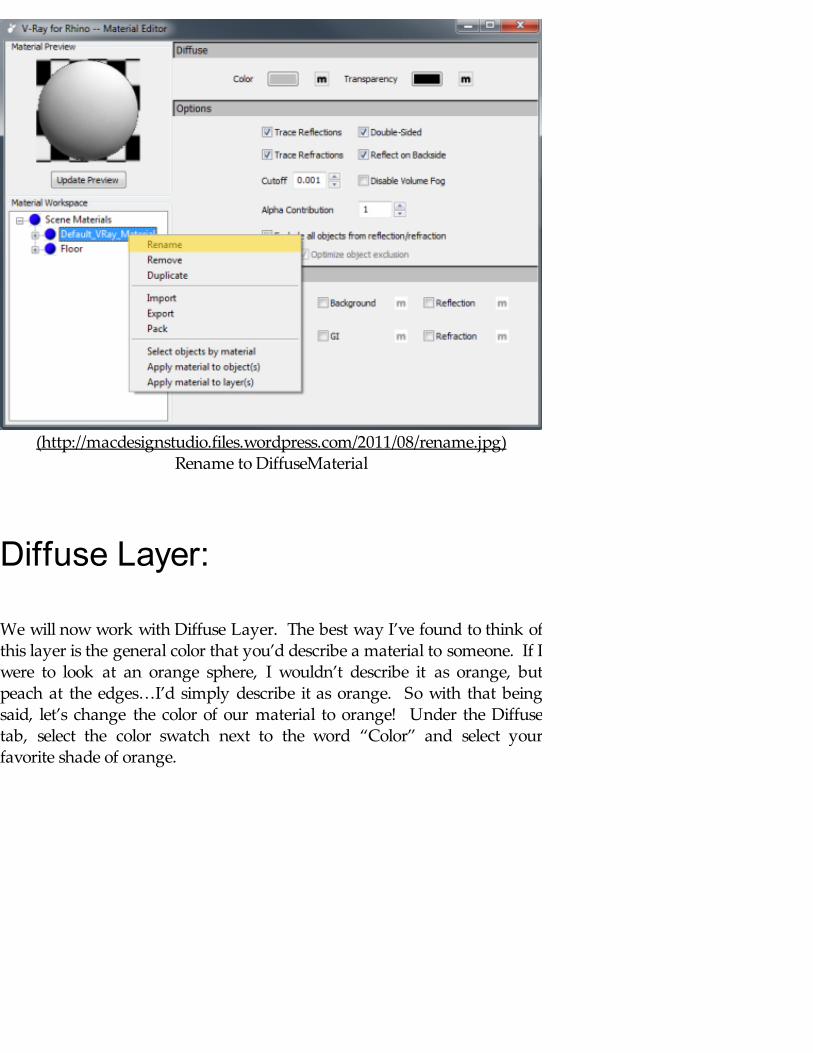
(http://macdesignstudio.files.wordpress.com/2011/08/rename.jpg)Rename to DiffuseMaterial
Diffuse Layer:
We will now work with Diffuse Layer. The best way I’ve found to think ofthis layer is the general color that you’d describe a material to someone. If Iwere to look at an orange sphere, I wouldn’t describe it as orange, butpeach at the edges…I’d simply describe it as orange. So with that beingsaid, let’s change the color of our material to orange! Under the Diffusetab, select the color swatch next to the word “Color” and select yourfavorite shade of orange.
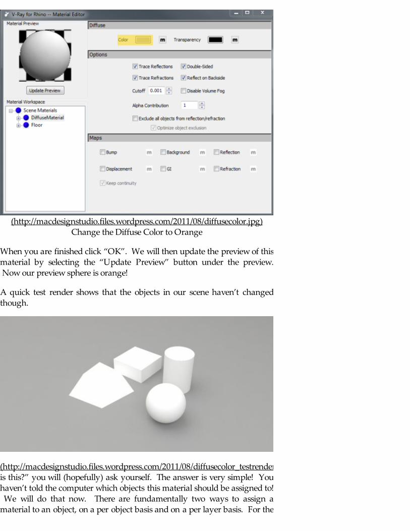
(http://macdesignstudio.files.wordpress.com/2011/08/diffusecolor.jpg)Change the Diffuse Color to Orange
When you are finished click “OK”. We will then update the preview of thismaterial by selecting the “Update Preview” button under the preview. Now our preview sphere is orange!
A quick test render shows that the objects in our scene haven’t changedthough.
(http://macdesignstudio.files.wordpress.com/2011/08/diffusecolor_testrender1.jpg)“Whyis this?” you will (hopefully) ask yourself. The answer is very simple! Youhaven’t told the computer which objects this material should be assigned to! We will do that now. There are fundamentally two ways to assign amaterial to an object, on a per object basis and on a per layer basis. For the
most part, I like to assign most materials by layers. This makes it easy forensuring that all objects on a layer are assigned the same material. Forexample, if I’m creating an exterior architectural rendering where I wantALL my exterior walls to be brick, this technique saves me time fromhaving to select each individual wall to ensure that the material is assignedto those walls. However, there are certain times that assigning a materialon a per object basis is more advantageous. Let’s say I’m doing an interiorarchitectural rendering where I have 5 magazines laying on a coffee table. I want each magazine object to be the cover of a different magazine andtherefore would rather assign each magazine on a per object basis (so Idon’t have to create 5 seperate layers for what is essentially the sameobject). At the end of the day, the choice is yours, I only suggest you thinkthrough the ramifications of your selection of these techniques.
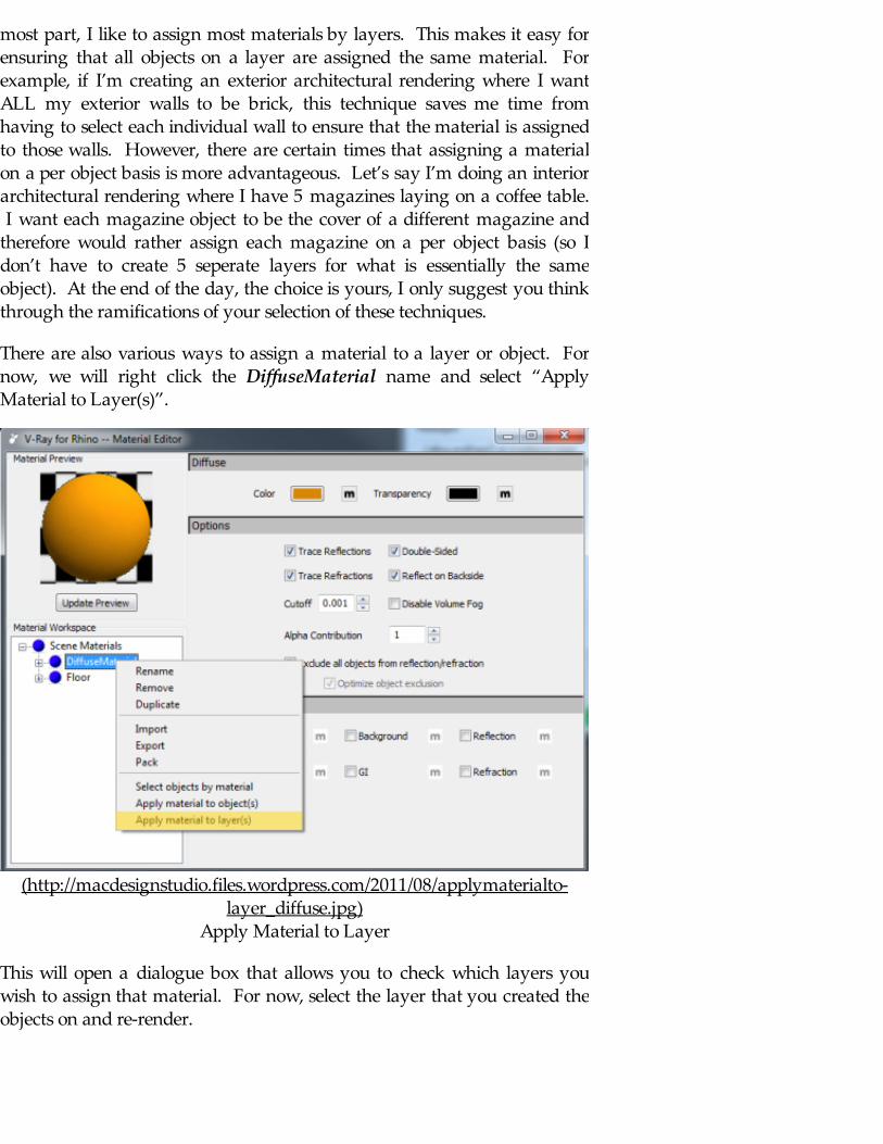
There are also various ways to assign a material to a layer or object. Fornow, we will right click the DiffuseMaterial name and select “ApplyMaterial to Layer(s)”.
(http://macdesignstudio.files.wordpress.com/2011/08/applymaterialto-layer_diffuse.jpg)
Apply Material to Layer
This will open a dialogue box that allows you to check which layers youwish to assign that material. For now, select the layer that you created theobjects on and re-render.
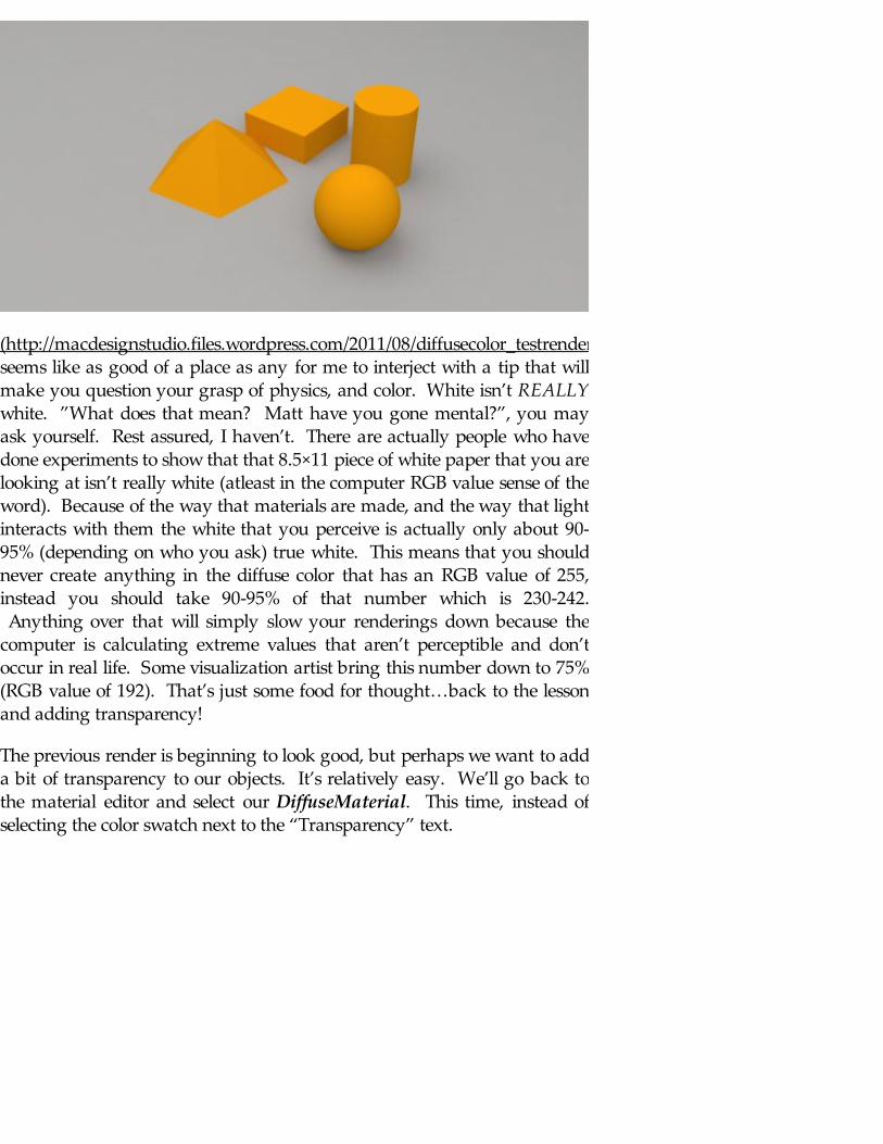
(http://macdesignstudio.files.wordpress.com/2011/08/diffusecolor_testrender_applied.jpg)Thisseems like as good of a place as any for me to interject with a tip that willmake you question your grasp of physics, and color. White isn’t REALLYwhite. ”What does that mean? Matt have you gone mental?”, you mayask yourself. Rest assured, I haven’t. There are actually people who havedone experiments to show that that 8.5×11 piece of white paper that you arelooking at isn’t really white (atleast in the computer RGB value sense of theword). Because of the way that materials are made, and the way that lightinteracts with them the white that you perceive is actually only about 90-95% (depending on who you ask) true white. This means that you shouldnever create anything in the diffuse color that has an RGB value of 255,instead you should take 90-95% of that number which is 230-242. Anything over that will simply slow your renderings down because thecomputer is calculating extreme values that aren’t perceptible and don’toccur in real life. Some visualization artist bring this number down to 75%(RGB value of 192). That’s just some food for thought…back to the lessonand adding transparency!
The previous render is beginning to look good, but perhaps we want to adda bit of transparency to our objects. It’s relatively easy. We’ll go back tothe material editor and select our DiffuseMaterial. This time, instead ofselecting the color swatch next to the “Transparency” text.

(http://macdesignstudio.files.wordpress.com/2011/08/diffusetransparency.jpg)Select Transparency Color
Unlike the Diffuse Color swatch, the Transparency swatch works on a greyscale. When this color is 100% black (RGB value 0), it’s 100% opaque. When it’s 100% white (RGB 255…yes, it’s ok to use in cases that aren’t thediffuse color), it’s 100% transparent. If I wanted the material to be 50%transparent, I would change the transparency swatch to be medium grey(RGB value 128). Let’s try this and see what happens.
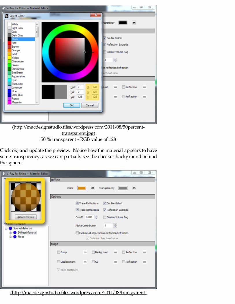
(http://macdesignstudio.files.wordpress.com/2011/08/50percent-transparent.jpg)
50 % transparent - RGB value of 128
Click ok, and update the preview. Notice how the material appears to havesome transparency, as we can partially see the checker background behindthe sphere.
(http://macdesignstudio.files.wordpress.com/2011/08/transparent-
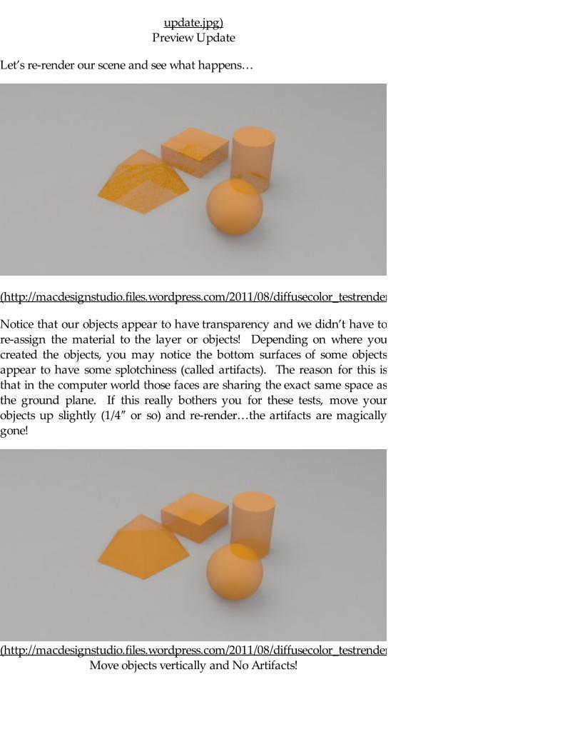
update.jpg)Preview Update
Let’s re-render our scene and see what happens…
(http://macdesignstudio.files.wordpress.com/2011/08/diffusecolor_testrender_transparency.jpg)
Notice that our objects appear to have transparency and we didn’t have tore-assign the material to the layer or objects! Depending on where youcreated the objects, you may notice the bottom surfaces of some objectsappear to have some splotchiness (called artifacts). The reason for this isthat in the computer world those faces are sharing the exact same space asthe ground plane. If this really bothers you for these tests, move yourobjects up slightly (1/4″ or so) and re-render…the artifacts are magicallygone!
(http://macdesignstudio.files.wordpress.com/2011/08/diffusecolor_testrender_transparency_noartifacts.jpg)Move objects vertically and No Artifacts!
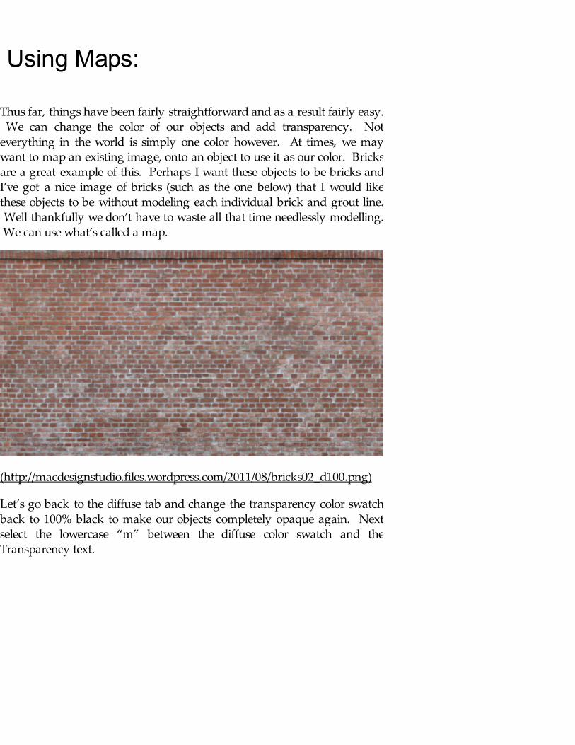
Using Maps:
Thus far, things have been fairly straightforward and as a result fairly easy. We can change the color of our objects and add transparency. Noteverything in the world is simply one color however. At times, we maywant to map an existing image, onto an object to use it as our color. Bricksare a great example of this. Perhaps I want these objects to be bricks andI’ve got a nice image of bricks (such as the one below) that I would likethese objects to be without modeling each individual brick and grout line. Well thankfully we don’t have to waste all that time needlessly modelling. We can use what’s called a map.
(http://macdesignstudio.files.wordpress.com/2011/08/bricks02_d100.png)
Let’s go back to the diffuse tab and change the transparency color swatchback to 100% black to make our objects completely opaque again. Nextselect the lowercase “m” between the diffuse color swatch and theTransparency text.
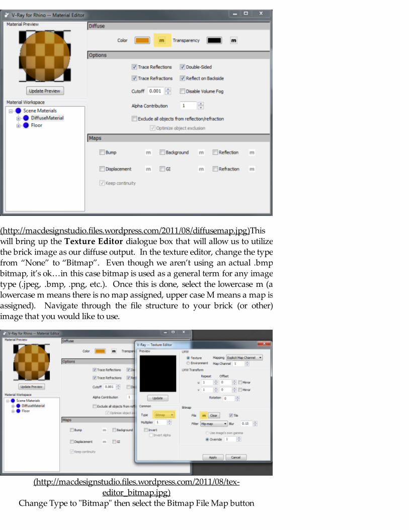
(http://macdesignstudio.files.wordpress.com/2011/08/diffusemap.jpg)Thiswill bring up the Texture Editor dialogue box that will allow us to utilizethe brick image as our diffuse output. In the texture editor, change the typefrom “None” to “Bitmap”. Even though we aren’t using an actual .bmpbitmap, it’s ok…in this case bitmap is used as a general term for any imagetype (.jpeg, .bmp, .png, etc.). Once this is done, select the lowercase m (alowercase m means there is no map assigned, upper case M means a map isassigned). Navigate through the file structure to your brick (or other)image that you would like to use.
(http://macdesignstudio.files.wordpress.com/2011/08/tex-editor_bitmap.jpg)
Change Type to "Bitmap" then select the Bitmap File Map button
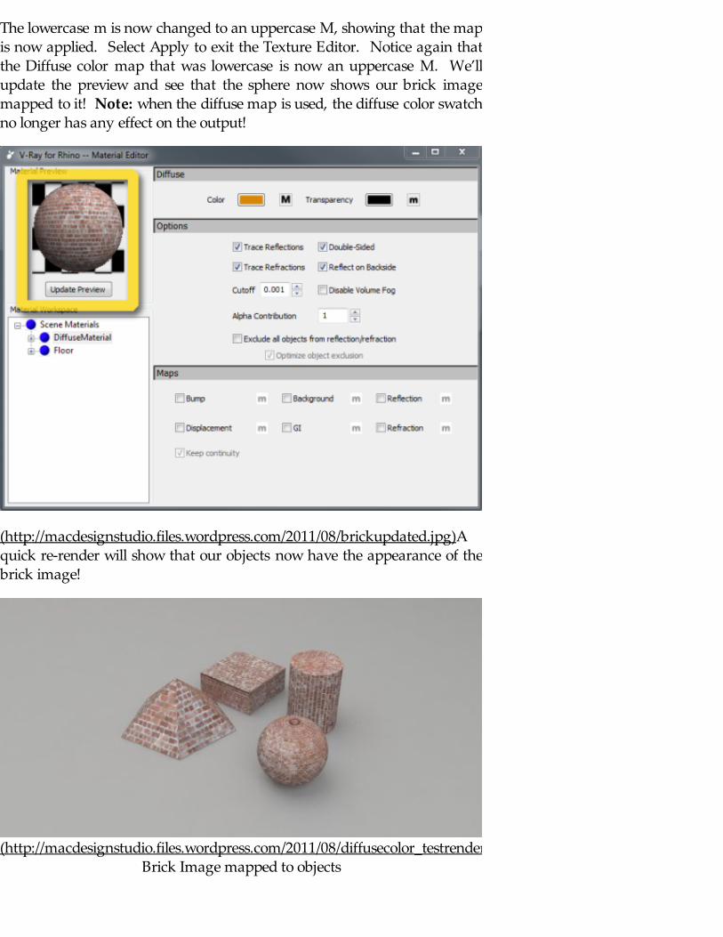
The lowercase m is now changed to an uppercase M, showing that the mapis now applied. Select Apply to exit the Texture Editor. Notice again thatthe Diffuse color map that was lowercase is now an uppercase M. We’llupdate the preview and see that the sphere now shows our brick imagemapped to it! Note: when the diffuse map is used, the diffuse color swatchno longer has any effect on the output!
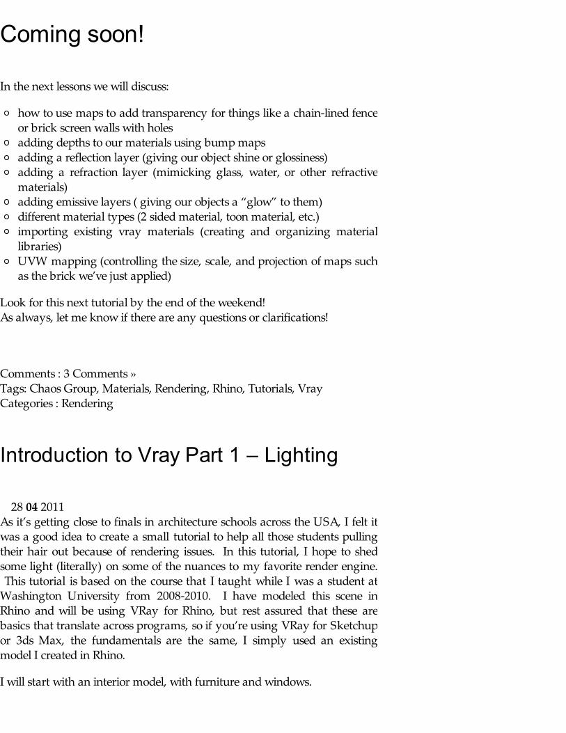
(http://macdesignstudio.files.wordpress.com/2011/08/brickupdated.jpg)Aquick re-render will show that our objects now have the appearance of thebrick image!
(http://macdesignstudio.files.wordpress.com/2011/08/diffusecolor_testrender_brick.jpg)Brick Image mapped to objects
Coming soon!
In the next lessons we will discuss:
how to use maps to add transparency for things like a chain-lined fenceor brick screen walls with holesadding depths to our materials using bump mapsadding a reflection layer (giving our object shine or glossiness)adding a refraction layer (mimicking glass, water, or other refractivematerials)adding emissive layers ( giving our objects a “glow” to them)different material types (2 sided material, toon material, etc.)importing existing vray materials (creating and organizing materiallibraries)UVW mapping (controlling the size, scale, and projection of maps suchas the brick we’ve just applied)
Look for this next tutorial by the end of the weekend!As always, let me know if there are any questions or clarifications!
Comments : 3 Comments » Tags: Chaos Group, Materials, Rendering, Rhino, Tutorials, Vray Categories : Rendering
Introduction to Vray Part 1 – Lighting
As it’s getting close to finals in architecture schools across the USA, I felt itwas a good idea to create a small tutorial to help all those students pullingtheir hair out because of rendering issues. In this tutorial, I hope to shedsome light (literally) on some of the nuances to my favorite render engine. This tutorial is based on the course that I taught while I was a student atWashington University from 2008-2010. I have modeled this scene inRhino and will be using VRay for Rhino, but rest assured that these arebasics that translate across programs, so if you’re using VRay for Sketchupor 3ds Max, the fundamentals are the same, I simply used an existingmodel I created in Rhino.
I will start with an interior model, with furniture and windows.
28 04 2011
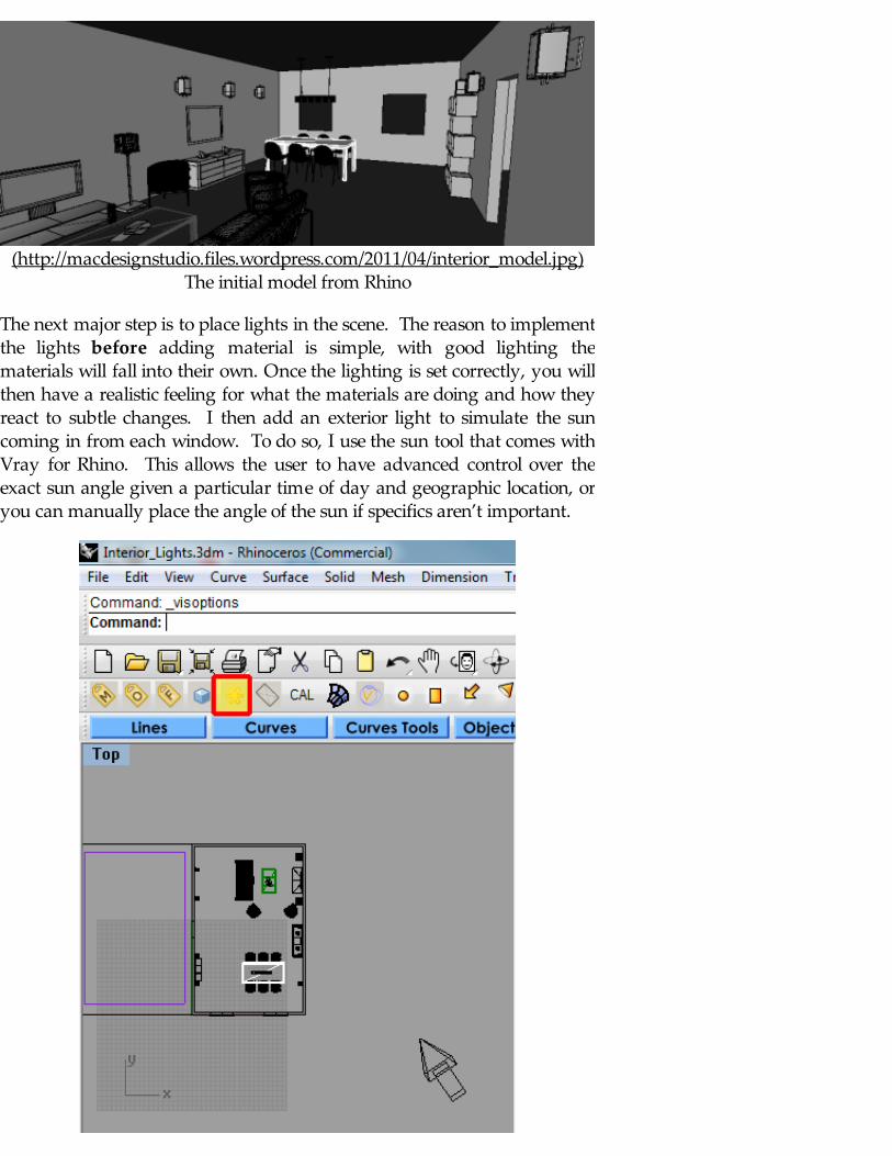
(http://macdesignstudio.files.wordpress.com/2011/04/interior_model.jpg)The initial model from Rhino
The next major step is to place lights in the scene. The reason to implementthe lights before adding material is simple, with good lighting thematerials will fall into their own. Once the lighting is set correctly, you willthen have a realistic feeling for what the materials are doing and how theyreact to subtle changes. I then add an exterior light to simulate the suncoming in from each window. To do so, I use the sun tool that comes withVray for Rhino. This allows the user to have advanced control over theexact sun angle given a particular time of day and geographic location, oryou can manually place the angle of the sun if specifics aren’t important.

(http://macdesignstudio.files.wordpress.com/2011/04/sun-button.jpg)
The exact location that the sun is placed in the scene doesn’t matter at allbecause, like in the real world, the sun shoot an infinite number of rays in aparallel direction to each other throughout the entire scene. It should benoted that this sunlighting system works only when using the VrayPhysical Camera in the Camera settings, but I will go more in depth aboutthis later.
(http://macdesignstudio.files.wordpress.com/2011/04/sun-rays.jpg)
The next step is to add rectangular lights at the openings to supplement thesunlight system. This helps to create additional light as well as add a bit ofrealism to the scene by focusing more light at the openings, a phenomenathat also occurs in nature. To do so, create a rectangular light that isslightly larger than the opening, ensuring that the light is pointing into theroom.
(http://macdesignstudio.files.wordpress.com/2011/04/rectangular-light.jpg)

(http://macdesignstudio.files.wordpress.com/2011/04/rect-light-point.jpg)
To manipulate the lighting settings for the rectangular lights, select the lightand in the properties tab, select the roll down and change it from “Object”to “Light”. The multiplier value for these rectangular lights will depend ona few factors (camera settings, and size of the light mostly), but a fewthings to keep in mind, that you should select “light portal”. This tells theprogram that it is to be used to supplement the existing light from theexterior, similar to the way a light comes into a window. We also want toensure that the light is “invisible”, so we can see through it and see theexterior of our scene. In this case, we don’t need to have the light be doublesided because we’re only interested in focusing the light’s energy to theinterior of the scene.
Light Multiplier settings:
(http://macdesignstudio.files.wordpress.com/2011/04/light-multiplier.jpg)Light Multiplier Values change intensity of light source
Visible Light vs. Invisible Light Source, notice the intensity doesn’t change:
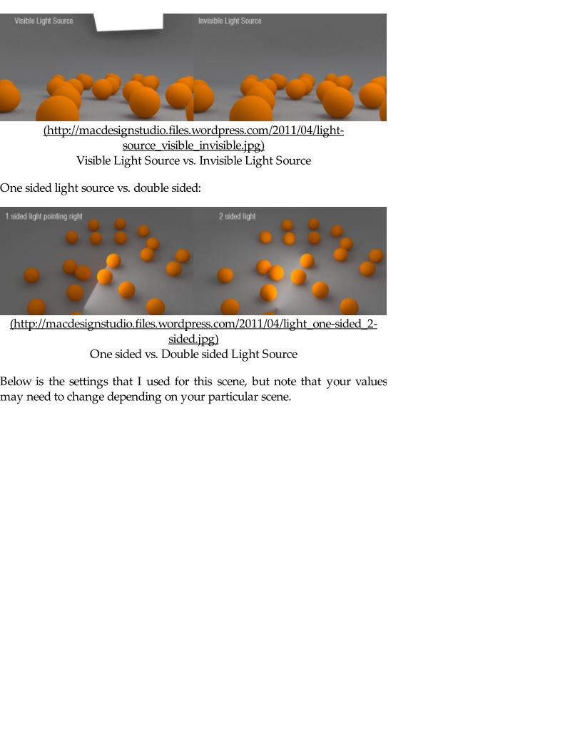
(http://macdesignstudio.files.wordpress.com/2011/04/light-source_visible_invisible.jpg)
Visible Light Source vs. Invisible Light Source
One sided light source vs. double sided:
(http://macdesignstudio.files.wordpress.com/2011/04/light_one-sided_2-sided.jpg)
One sided vs. Double sided Light Source
Below is the settings that I used for this scene, but note that your valuesmay need to change depending on your particular scene.
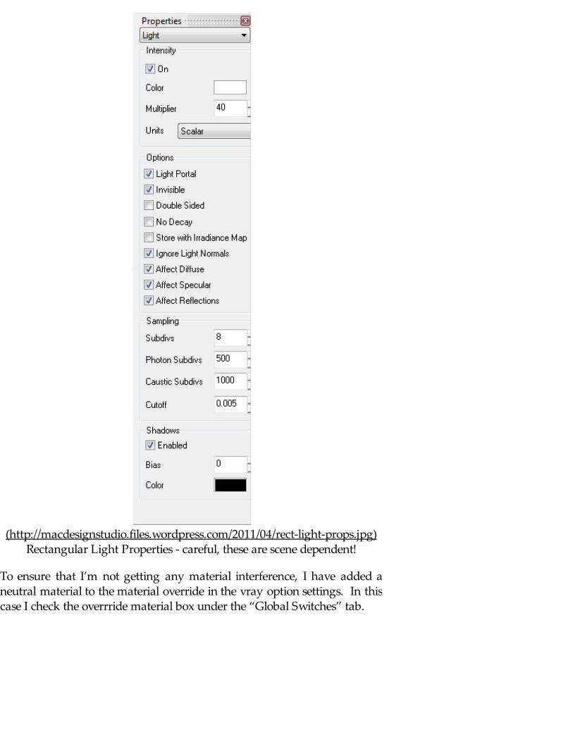
(http://macdesignstudio.files.wordpress.com/2011/04/rect-light-props.jpg)Rectangular Light Properties - careful, these are scene dependent!
To ensure that I’m not getting any material interference, I have added aneutral material to the material override in the vray option settings. In thiscase I check the overrride material box under the “Global Switches” tab.

(http://macdesignstudio.files.wordpress.com/2011/04/override-material.jpg)Override Material with color over 128-128-128, a medium grey
In order to allow the light to come through the openings, I must hide thewindows in the Rhino model, even if we’ve added a glass material to thewindows because the material override will override all materials includingthe glass.
This seems like a good time to do a test render, but first we must look atsome of the other rendering settings in our render options. The first tab thatwe should focus on is the Global Switches tab. We want to ensure thatlighting is checked, letting the program know that it needs to calculate thelighting. We however don’t want to have the Hidden Lights boxed checkedbecause if we hid some lights in the scene, we shouldn’t have thosecalculate, we just want to see the effect of the lights that are shown in ourscene. We also don’t want to select the Default Lights box because we haveplaced lights in our scene and want to use only the lights that we haveplaced and have control over.
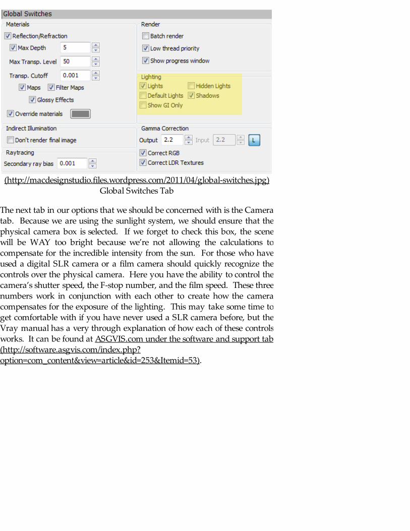
(http://macdesignstudio.files.wordpress.com/2011/04/global-switches.jpg)Global Switches Tab
The next tab in our options that we should be concerned with is the Cameratab. Because we are using the sunlight system, we should ensure that thephysical camera box is selected. If we forget to check this box, the scenewill be WAY too bright because we’re not allowing the calculations tocompensate for the incredible intensity from the sun. For those who haveused a digital SLR camera or a film camera should quickly recognize thecontrols over the physical camera. Here you have the ability to control thecamera’s shutter speed, the F-stop number, and the film speed. These threenumbers work in conjunction with each other to create how the cameracompensates for the exposure of the lighting. This may take some time toget comfortable with if you have never used a SLR camera before, but theVray manual has a very through explanation of how each of these controlsworks. It can be found at ASGVIS.com under the software and support tab(http://software.asgvis.com/index.php?option=com_content&view=article&id=253&Itemid=53).
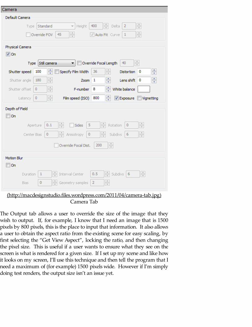
(http://macdesignstudio.files.wordpress.com/2011/04/camera-tab.jpg)Camera Tab
The Output tab allows a user to override the size of the image that theywish to output. If, for example, I know that I need an image that is 1500pixels by 800 pixels, this is the place to input that information. It also allowsa user to obtain the aspect ratio from the existing scene for easy scaling, byfirst selecting the “Get View Aspect”, locking the ratio, and then changingthe pixel size. This is useful if a user wants to ensure what they see on thescreen is what is rendered for a given size. If I set up my scene and like howit looks on my screen, I’ll use this technique and then tell the program that Ineed a maximum of (for example) 1500 pixels wide. However if I’m simplydoing test renders, the output size isn’t an issue yet.

(http://macdesignstudio.files.wordpress.com/2011/04/output-tab.jpg)Output Tab with ability to change rendering size
The Environment tab gives the user the ability to create the environmentallighting (not the direct sunlight, but the light from the sky) and control howit is handled in the scene. Because we have created a sunlight system, it’spossible to link the position of the sun light to the environmental light. Bylinking the two, we will get a reddish light as the sun approaches thehorizon as occurs in nature, as the light comes closer to noon, theenvironmental light will become more blueish. To link the sunlight positionto the environmental lighting, select the little “m” next to the GI (skylight)check box.
(http://macdesignstudio.files.wordpress.com/2011/04/gi.jpg)Select the little "m" to apply a map
When this is selected, a new Map texture editor pop up will appear. Change the type from “none” to “Sky”.
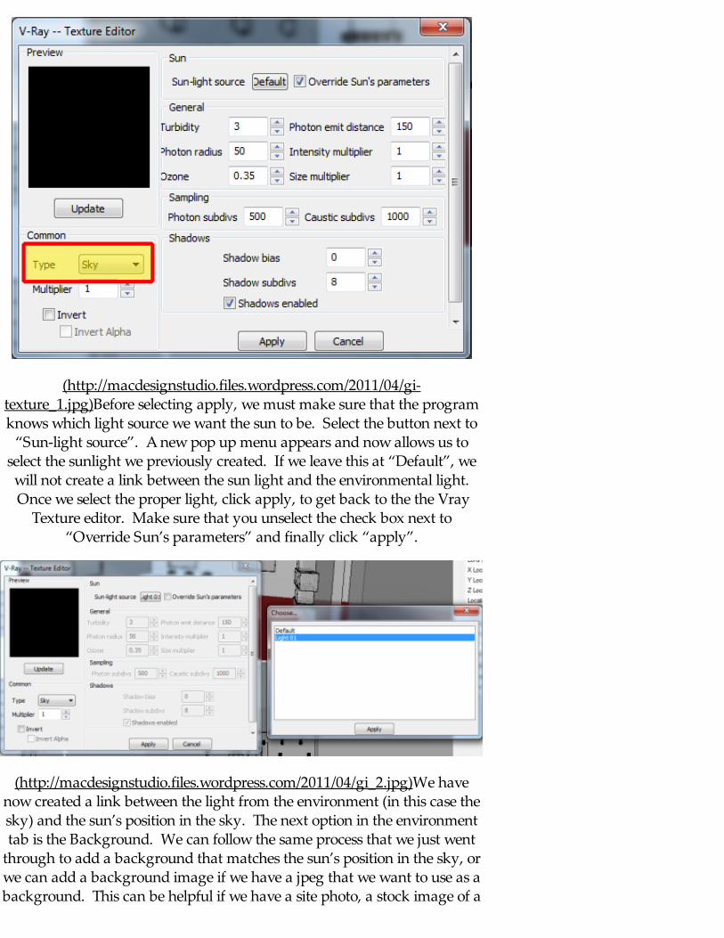
(http://macdesignstudio.files.wordpress.com/2011/04/gi-texture_1.jpg)Before selecting apply, we must make sure that the programknows which light source we want the sun to be. Select the button next to
“Sun-light source”. A new pop up menu appears and now allows us toselect the sunlight we previously created. If we leave this at “Default”, wewill not create a link between the sun light and the environmental light. Once we select the proper light, click apply, to get back to the the Vray
Texture editor. Make sure that you unselect the check box next to“Override Sun’s parameters” and finally click “apply”.
(http://macdesignstudio.files.wordpress.com/2011/04/gi_2.jpg)We havenow created a link between the light from the environment (in this case thesky) and the sun’s position in the sky. The next option in the environmenttab is the Background. We can follow the same process that we just went
through to add a background that matches the sun’s position in the sky, orwe can add a background image if we have a jpeg that we want to use as abackground. This can be helpful if we have a site photo, a stock image of a
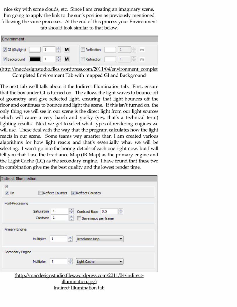
nice sky with some clouds, etc. Since I am creating an imaginary scene,I’m going to apply the link to the sun’s position as previously mentioned
following the same processes. At the end of this process your Environmenttab should look similar to that below.
(http://macdesignstudio.files.wordpress.com/2011/04/environment_complete.jpg)Completed Environment Tab with mapped GI and Background
The next tab we’ll talk about it the Indirect Illumination tab. First, ensurethat the box under GI is turned on. The allows the light waves to bounce offof geometry and give reflected light, ensuring that light bounces off thefloor and continues to bounce and light the scene. If this isn’t turned on, theonly thing we will see in our scene is the direct light from our light sourceswhich will cause a very harsh and yucky (yes, that’s a technical term)lighting results. Next we get to select what types of rendering engines wewill use. These deal with the way that the program calculates how the lightreacts in our scene. Some teams way smarter than I am created variousalgorithms for how light reacts and that’s essentially what we will beselecting. I won’t go into the boring details of each one right now, but I willtell you that I use the Irradiance Map (IR Map) as the primary engine andthe Light Cache (LC) as the secondary engine. I have found that these twoin combination give me the best quality and the lowest render time.
(http://macdesignstudio.files.wordpress.com/2011/04/indirect-illumination.jpg)
Indirect Illumination tab
For test renders I use the following value under my IR Map tab, in the next
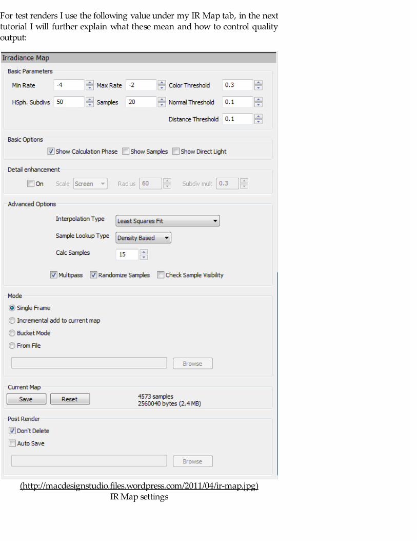
For test renders I use the following value under my IR Map tab, in the nexttutorial I will further explain what these mean and how to control qualityoutput:
(http://macdesignstudio.files.wordpress.com/2011/04/ir-map.jpg)IR Map settings
And the following are the typical LC settings I use for test renders, please
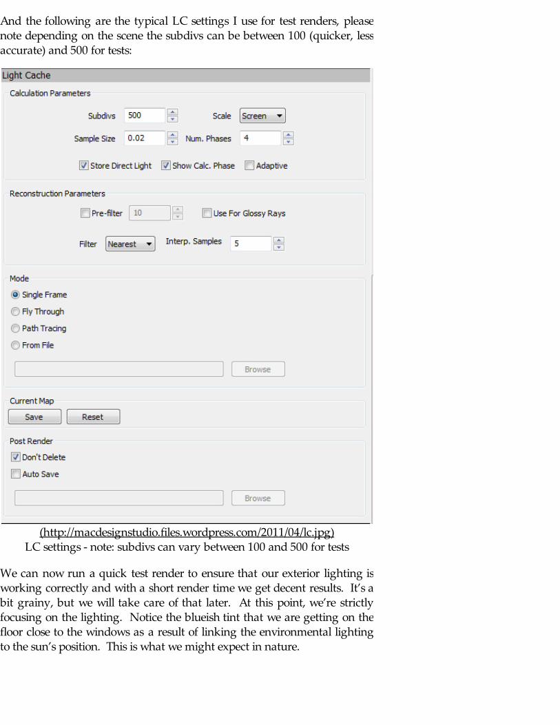
And the following are the typical LC settings I use for test renders, pleasenote depending on the scene the subdivs can be between 100 (quicker, lessaccurate) and 500 for tests:
(http://macdesignstudio.files.wordpress.com/2011/04/lc.jpg)LC settings - note: subdivs can vary between 100 and 500 for tests
We can now run a quick test render to ensure that our exterior lighting isworking correctly and with a short render time we get decent results. It’s abit grainy, but we will take care of that later. At this point, we’re strictlyfocusing on the lighting. Notice the blueish tint that we are getting on thefloor close to the windows as a result of linking the environmental lightingto the sun’s position. This is what we might expect in nature.
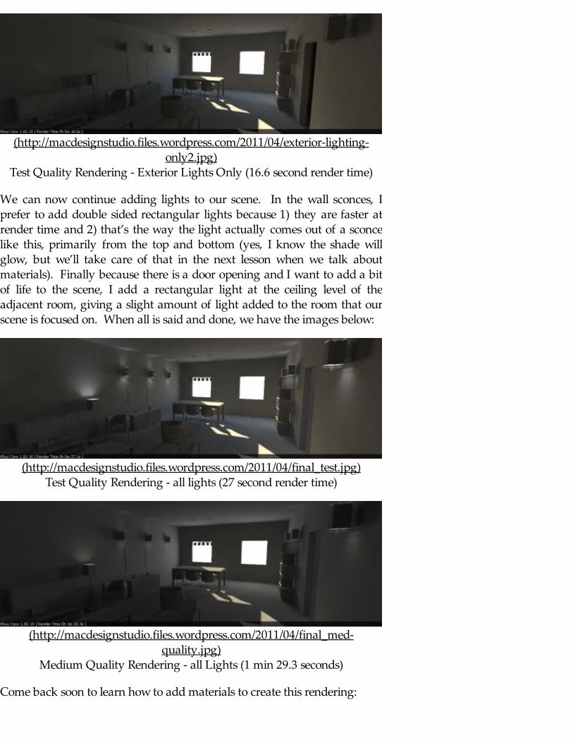
(http://macdesignstudio.files.wordpress.com/2011/04/exterior-lighting-only2.jpg)
Test Quality Rendering - Exterior Lights Only (16.6 second render time)
We can now continue adding lights to our scene. In the wall sconces, Iprefer to add double sided rectangular lights because 1) they are faster atrender time and 2) that’s the way the light actually comes out of a sconcelike this, primarily from the top and bottom (yes, I know the shade willglow, but we’ll take care of that in the next lesson when we talk aboutmaterials). Finally because there is a door opening and I want to add a bitof life to the scene, I add a rectangular light at the ceiling level of theadjacent room, giving a slight amount of light added to the room that ourscene is focused on. When all is said and done, we have the images below:
(http://macdesignstudio.files.wordpress.com/2011/04/final_test.jpg)Test Quality Rendering - all lights (27 second render time)
(http://macdesignstudio.files.wordpress.com/2011/04/final_med-quality.jpg)
Medium Quality Rendering - all Lights (1 min 29.3 seconds)
Come back soon to learn how to add materials to create this rendering:

(http://macdesignstudio.files.wordpress.com/2011/04/interior-medium-setting-final.jpg)
Final Rendering with Materials
Comments : 17 Comments » Tags: Lighting, Tutorials, Vray Categories : Rendering
Blog at WordPress.com. The Freshy Theme.
Follow
Follow “macdesignstudio”
Powered by WordPress.com