Embed Size (px)
Citation preview
REMY TECHNICALSERVICE BULLETIN
Sign up to receive the Remy Technical Service Bulletin at remyautoparts.com
December 2015
>>>
Find all the Remy Technical Service Bulletins
at remyautoparts.com
Voltage Drop: Solving the Root Causes of Charging System Failures
Repeat charging system failures are most often traced to vehicle concerns. A voltage drop in the power or ground circuits of an alternator can cause premature failure and is often the source of misdiagnosis. To prevent early failures or reduced charging system voltage, you should always perform voltage drop tests as part of a charging system diagnosis. In this issue, we’ll provide you the necessary information to accurately measure charging system voltage drop.
What is voltage drop?In every operating circuit there is voltage used by each component, connection and wire. Figure 1 below shows a simple lamp circuit and normal voltage drops. Compare those readings to the ones in Figure 2 where the bulb is dimly lit. Excessive voltage is being used in the ground circuit to overcome the resistance, preventing the bulb from lighting up as brightly.
Voltage drop in the charging system can cause multiple symptoms, depending upon the location of the voltage drop:
• Undercharge or overcharge
• Failed battery as a result of under/overcharge• Repeat alternator replacement or misdiagnosis• Other vehicle electrical issues
Performing a Voltage Drop TestWhile these tests are most accurate with the aid of a carbon pile, we’ll review how to perform these tests using the vehicle as the load.
Note: There must be current flow for voltage drop to occur. For this reason you cannot perform this voltage drop test on a vehicle with a failed charging system. Make the necessary repairs to the charging system before conducting this voltage drop test.
Figure 1 Figure 2
Remy Power Products600 Corporation Drive
Pendleton, IN 46064 USA 800-854-0076
remyautoparts.com
We start the world and keep it running.™
If you have questions or need assistance, contact Remy Technical Support at 800-854-0076
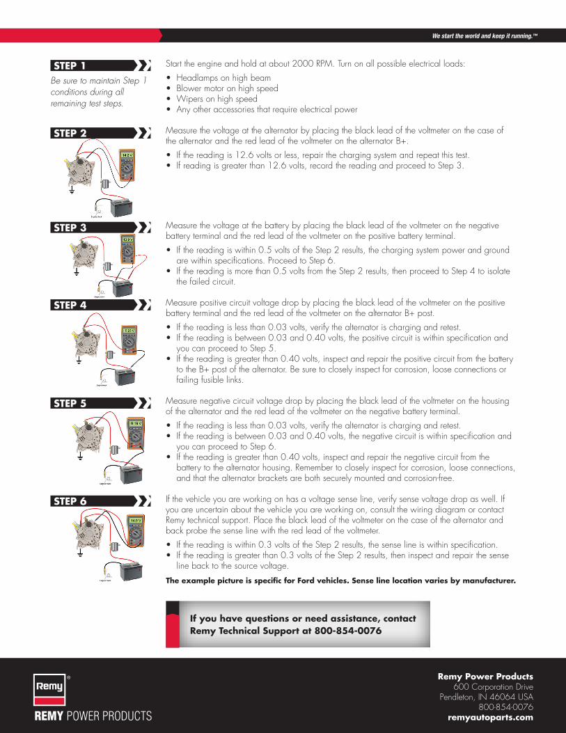
Start the engine and hold at about 2000 RPM. Turn on all possible electrical loads:
• Headlamps on high beam• Blower motor on high speed• Wipers on high speed• Any other accessories that require electrical power
Measure the voltage at the alternator by placing the black lead of the voltmeter on the case of the alternator and the red lead of the voltmeter on the alternator B+.
• If the reading is 12.6 volts or less, repair the charging system and repeat this test. • If reading is greater than 12.6 volts, record the reading and proceed to Step 3.
Measure the voltage at the battery by placing the black lead of the voltmeter on the negative battery terminal and the red lead of the voltmeter on the positive battery terminal.
• If the reading is within 0.5 volts of the Step 2 results, the charging system power and ground are within specifications. Proceed to Step 6.
• If the reading is more than 0.5 volts from the Step 2 results, then proceed to Step 4 to isolate the failed circuit.
Measure positive circuit voltage drop by placing the black lead of the voltmeter on the positive battery terminal and the red lead of the voltmeter on the alternator B+ post.
• If the reading is less than 0.03 volts, verify the alternator is charging and retest.• If the reading is between 0.03 and 0.40 volts, the positive circuit is within specification and
you can proceed to Step 5.• If the reading is greater than 0.40 volts, inspect and repair the positive circuit from the battery
to the B+ post of the alternator. Be sure to closely inspect for corrosion, loose connections or failing fusible links.
Measure negative circuit voltage drop by placing the black lead of the voltmeter on the housing of the alternator and the red lead of the voltmeter on the negative battery terminal.
• If the reading is less than 0.03 volts, verify the alternator is charging and retest.• If the reading is between 0.03 and 0.40 volts, the negative circuit is within specification and
you can proceed to Step 6.• If the reading is greater than 0.40 volts, inspect and repair the negative circuit from the
battery to the alternator housing. Remember to closely inspect for corrosion, loose connections, and that the alternator brackets are both securely mounted and corrosion-free.
If the vehicle you are working on has a voltage sense line, verify sense voltage drop as well. If you are uncertain about the vehicle you are working on, consult the wiring diagram or contact Remy technical support. Place the black lead of the voltmeter on the case of the alternator and back probe the sense line with the red lead of the voltmeter.
• If the reading is within 0.3 volts of the Step 2 results, the sense line is within specification.• If the reading is greater than 0.3 volts of the Step 2 results, then inspect and repair the sense
line back to the source voltage.
The example picture is specific for Ford vehicles. Sense line location varies by manufacturer.
STEP 1
STEP 2
STEP 3
STEP 4
STEP 5
STEP 6
Be sure to maintain Step 1 conditions during all remaining test steps.
››
››
››
››
››
››