Embed Size (px)
Citation preview

Removal Procedures
***Take a picture of the
transmission and note the
lever positions
(Transmission Arm Lever
points up and Kickdown
Lever point down)***
This is an aluminum-case
PowerGlide Transmission
out of a 1966 Chevelle.
At this point shift the Shift
Selector Shaft to get a feel
of the resistance between
the ranges and how the shaft
generally operates.
Notice the fixed levers both
on the shift selector shaft
and the kicked down shaft.
This is what you will be
changing
Start by removing all 14
Transmission Pan bolts
and use the pan to hold all
of your parts so that none
are lost.
***It is recommended that
you replace the
Transmission Pan Gasket
and Filter which is not
included in this kit but can
be bought separately at
your local parts store.***

This is the Parking Pawl Guide
Plate. Start by removing the two
bolts that secure it down. When
removing the bolts be sure that they
stay in their proper positions and
place the part in the transmission
pan (parts bin).
Next we are removing the
Roller Spring/Retainer
Plate and spring from the
valve body. These pieces
provide tension for the
Parking Pawl Roller.
Be sure that when you are
removing the bolt and plate
that you put a finger on the
top of the spring where it
contacts its retaining plate
so it is not lost during
removal. If it does you
should be able to retrieve it
with a magnet.
Next loosen both clamps
that are attached to the Shift
Selector Shaft (main shaft)
and Kick-Down Shaft.
***Caution: do not
completely undo bolts or
parts may be lost into the
transmission.***
To loosen you will either
need an Allen wrench or a
12 point ¼ inch socket.

After both clamps are loose
firmly hold the smaller
clamp with thumb and index
finger and pull up on the
Kick-Down Shaft by using
the lever and place shaft in
pan along with the small
clamp.
Next we remove the Shift
Selector Shaft by pulling up
on the lever being sure not
to move the parking pawl
too much.
After, place the Kick-Down
Shaft into the main shaft
and set aside as it will not be
reused.

***At this point since the shaft is
out it is recommended that you
replace the Shift Selector Shaft
Seal. ***
Available from:
www.TransmissionPartsUSA.com
and
www.ClassicTransmissionSolutions
.com
Preparations for Shiftworks
Kickdown Shaft: First
install the Retainer with the
flat side towards the
threaded end, with the ridge
side so that it pushed against
the O-Ring. O-Ring is
placed on Shiftworks Kick-
Down Shaft last and pushed
up against its Retainer
towards the threads. After it
is lubricate it with
transmission oil. Attach the
provided Shiftworks
PowerGlide Cable Lever and Shiftworks Kick-Down
Lever and hand tight only
*** Caution: do not place
shaft in any sort of gripping
mechanism to tighten (I.E.
vice grips, vice, channel
locks, pliers etc.)***

Installation Procedures Cable Application
Take the Shiftworks Shift Selector
Shaft (without the Kick-Down inside
it as it will make installation a little
easier) and put it in the Shaft hole
and simultaneously hold the Parking
Pawl Clamp (the bigger of the two).
Move the shaft back and forth
rotationally until it goes through the
clamp and rests flush against the
clamp. Ensure that the cable lever is
pointed down towards the pan and
then tighten clamp to proper spec.

Then you must hold the smaller
clamp in position (facing same way
as original which was originally seen
before removal) then take the
Shiftworks Kick-Down Shaft and
place it back inside the Shiftworks
main shaft.
It will then fall through and as before
with the main shaft, rotate the
Shiftworks Kick-Down Shaft and
push it through the clamp(while still
holding clamp with other hand) .
Do not tighten yet. Before tightening
the smaller clamp ensure that the
Parking Pawl is lined up correctly on
the Parking Pawl Roller. Then
ensure Shiftworks Kick-Down Shaft
is fully seated in the Shiftworks
Main Shaft. After while still pushing
down on Kick-Down Shaft tighten
the smaller clamp so that it lays flush
against the base of the Shiftworks
Main Shaft(Doing this ensures the
Kick-Down Shaft will not move in or
out of the Main Shaft during
operation.)
At this point turn the shaft and ensure
that throughout the travel of the
Parking Pawl it is always lined up on
its roller and that the kick down lever
is facing forward. If it is it is time to
move on.
Now you must secure the Parking
Pawl Guide Plate. Ensure that the
tab from the Parking Pawl Roller is
in the slot on the Guide Plate. Then
place the bolts in the exact place that
they were removed from and secure
to proper specification.
***Once again, Shift the Selector
shaft and ensure that it moves easily
through slot and all ranges (P, R, N,
and D & L)***.

Now you will attach the Roller Retainer
Plate and Spring. Hold the spring
against the plate connected as it should
and loop the other end of the spring onto
the Parking pawl roller. Then place the
bolt through the retainer plate and tighten
to specifications.
***At this point you should recheck the
Parking Pawl & Roller for operation.
Ensure there is adequate tension and
that it goes through all gear ranges with
ease (P, R, N, and D & 1)***
Finished internal assembly should
look like this.
At this point all parts should be used
besides the Transmission Pan bolts.
You must secure the pan with gasket
to the transmission using proper
tightening specifications and
techniques. Then hook up shifter and
associated parts and it is ready to go.
Ensure levers are positioned like so
and you are ready Enjoy your newly
modified floor shifting
classic!!!!!!!!!!!!!
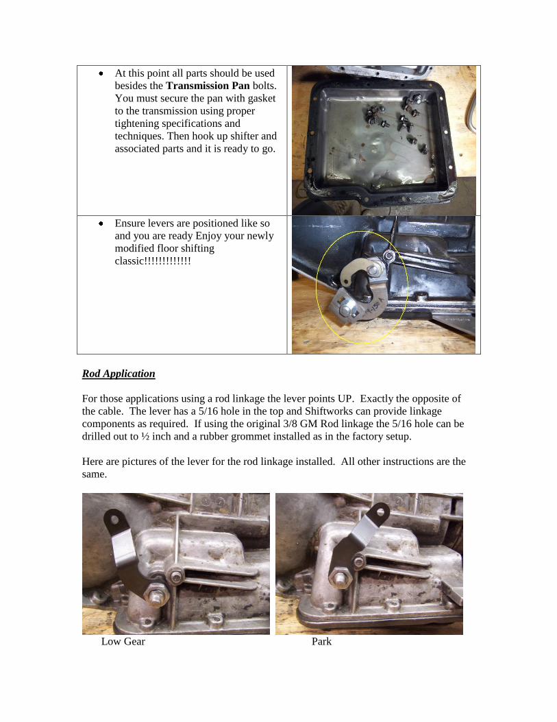
Rod Application
For those applications using a rod linkage the lever points UP. Exactly the opposite of
the cable. The lever has a 5/16 hole in the top and Shiftworks can provide linkage
components as required. If using the original 3/8 GM Rod linkage the 5/16 hole can be
drilled out to ½ inch and a rubber grommet installed as in the factory setup.
Here are pictures of the lever for the rod linkage installed. All other instructions are the
same.
Low Gear Park