Embed Size (px)
Citation preview
Remote Robot Vision Control of a Flexible Manufacturing Cell 455
Remote Robot Vision Control of a Flexible Manufacturing Cell
Silvia Anton, Florin Daniel Anton and Theodor Borangiu
X
Remote Robot Vision Control of a Flexible Manufacturing Cell
Silvia Anton, Florin Daniel Anton and Theodor Borangiu
University Politehnica of Bucharest Romania
1. Introduction
In a robotized flexible manufacturing cell, robot (-vision) controllers are masters over local workstations or cells, because robot manipulators connect two important material flows: the processing flow and the transportation flow. One solution to integrate these two flows with on-line quality control in the manufacturing module, further networked with the design and planning modules, is to adopt a unified feature-based description of parts and assemblies, technological operations, geometric & surface quality control, grasping and manipulating (Tomas Balibrea, et al., 1997). The chapter presents a system which can be used to unify, control and observe the cell's devices (in particular each robot-vision system) from a remote location for control and learning purposes, using an advanced web interface. The system is a software product designed to support multiple remote connections with a number of Adept Technology robot-vision controllers, either located in a local network, or via Internet. Additionally the platform allows users to run remote robot vision sessions and to develop and execute robot-vision programs, being a versatile tool for remote student training (Anton et al., 2006; Borangiu et al., 2006). The system has multiple functions: Observing locally the foreground of robot workplaces (processing area, storage, conveyor belt, part buffer, pallet) using multiple area cameras – stationary or mobile, arm mounted, and globally the robot workstation; Set up of the operating environment (lighting pattern, virtual camera configuration, feature selection for material flow description) and learning the model parameters for scene description, part recognition and measuring, part grasping and gripper fingerprints for collision avoidance; Editing, debugging and downloading application data and programs. Remote shared control of multiple robot systems from a central point and event-driven supervision of robot actions including reaction and emergency routines launching; Access via a Lotus Domino-based messaging and collaboration portal to a team workspace addressing hands-on team training and authenticated e-learning in the areas of computer aided design, planning, control and quality inspection for networked manufacturing workstations/cells (Brooks et al., 2004; Harris et al., 2004).
24
www.intechopen.com

Robot Vision456
2. The Structure of the System
The strong impact of the project is in stimulating the cooperation between different networked areas of an enterprise.
2.1 Technical Background The task is to build a system that provides access to public information for a wider audience and at the same time supports collaboration between registered members, provides safe access to protected contents and enables the publication and editing of contents. The system can be accessed from a great variety of places. Therefore great care was taken to also ensure optimal use in case of lower bandwidth and poorer quality hardware. The high level of security and availability are key components. This was ensured by the selection of high quality technical devices and the well-planned loading. As the portal must be prepared for a growing number of users, the tool must be highly scalable. It needs to integrate contents and services and provide access for document repositories. User groups must be able to access personalised contents. A first step to install a framework is to create the infrastructure that is necessary for the safe operation and use of the portal (Fig. 1).
Fig. 1. The connexion between the server application and Adept controllers High-level availability must be guaranteed. The system must be scalable according to loadness and requirements. The use of NLBS (Network Load Balancing System) provides a solution for an even load of the network. The portal user interface need to be customized, templates must be created and uploaded. The authorisations and user groups must be defined.
2.2 The Communication structure and protocol The application was built to remotely command and supervise robot systems that can be located into an industrial LAN or Internet. The materials flow is supervised locally for each station and the results are sent to the server application which stores them into a data base. The server uses the TCP/IP protocol to establish the connexion with the clients, the communication being achieved using messages and confirmations (Borangiu, 1996). The length of one message cannot be more than 128 bytes; this limit is imposed by the operating
www.intechopen.com
Remote Robot Vision Control of a Flexible Manufacturing Cell 457
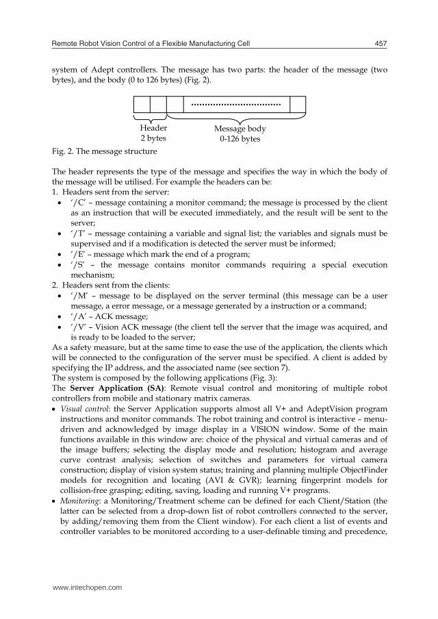
system of Adept controllers. The message has two parts: the header of the message (two bytes), and the body (0 to 126 bytes) (Fig. 2).
Fig. 2. The message structure The header represents the type of the message and specifies the way in which the body of the message will be utilised. For example the headers can be: 1. Headers sent from the server: ‘/C’ – message containing a monitor command; the message is processed by the client
as an instruction that will be executed immediately, and the result will be sent to the server;
‘/T’ – message containing a variable and signal list; the variables and signals must be supervised and if a modification is detected the server must be informed;
‘/E’ – message which mark the end of a program; ‘/S’ – the message contains monitor commands requiring a special execution
mechanism; 2. Headers sent from the clients: ‘/M’ – message to be displayed on the server terminal (this message can be a user
message, a error message, or a message generated by a instruction or a command; ‘/A’ – ACK message; ‘/V’ – Vision ACK message (the client tell the server that the image was acquired, and
is ready to be loaded to the server; As a safety measure, but at the same time to ease the use of the application, the clients which will be connected to the configuration of the server must be specified. A client is added by specifying the IP address, and the associated name (see section 7). The system is composed by the following applications (Fig. 3): The Server Application (SA): Remote visual control and monitoring of multiple robot controllers from mobile and stationary matrix cameras. Visual control: the Server Application supports almost all V+ and AdeptVision program
instructions and monitor commands. The robot training and control is interactive – menu-driven and acknowledged by image display in a VISION window. Some of the main functions available in this window are: choice of the physical and virtual cameras and of the image buffers; selecting the display mode and resolution; histogram and average curve contrast analysis; selection of switches and parameters for virtual camera construction; display of vision system status; training and planning multiple ObjectFinder models for recognition and locating (AVI & GVR); learning fingerprint models for collision-free grasping; editing, saving, loading and running V+ programs.
Monitoring: a Monitoring/Treatment scheme can be defined for each Client/Station (the latter can be selected from a drop-down list of robot controllers connected to the server, by adding/removing them from the Client window). For each client a list of events and controller variables to be monitored according to a user-definable timing and precedence,
Header 2 bytes
Message body 0-126 bytes
www.intechopen.com

Robot Vision458
and reacted at by user-definable actions/sequences can be specified in an Automatic Treatment Window.
Communication management: the Server Application manages the communication with the robot controllers and the observation cameras, transfers real-time images from the cameras observing the robot workplace and production environment, reports status information, stores in a database and displays images taken by the robot camera via its controller. Finally, the SA outputs commands which are received from the eClients or acknowledges task execution.
The eClients Applications (eCA): Java applications running in web browsers. They provide portal services and the connection of networked production agents: image data and RV program / report management; real-time robot control and cell / workplace observation. The eCA are composed by two applications: one application which has the function of retrieving the images from the observation
cameras (AXIS 214 PTZ) and display them in real-time and also gives the user the possibility to change the orientation and zoom factor of the cameras.
the second application is a VNC client. The VNC viewer (Java client) is a web teleoperation application which can be executed into a web browser. The application connects to the Domino web server which makes a secure connection using a TCP/IP tunnel with a server having a private IP address, which cannot be accessed from internet but only using the Domino server.
Fig. 3. The System Structure
www.intechopen.com

Remote Robot Vision Control of a Flexible Manufacturing Cell 459
The private IP machine has a VNC server that exports the display, and also the teleoperation application (see Fig. 4). Using the exported display the user can view and use the application as when the application runs on his own computer. The access is made using a username and a password, process managed by the Domino server.
Fig. 4. The VNC communication The access to the eClient application is granted based on the Domino defined ACL’s (Access Control Lists), such that in order to connect to the application the user must specify a user name and a password. There were defined two classes of privileges: A user class where the operator can observe images acquired from the observation web cameras and images from the VISION system taken by multiple area cameras; he can also view the commands issued by the trainer and watch the results of the commands; A trainer class where the operator is authorized to issue commands for every connected robot system, upload, download and modify programs. The trainer can also take pictures from an individual camera and use the specific vision tools to process that image. The observation cameras can also be moved and positioned in the desired location by the trainer. The trainer can give full or partial permissions to users for program testing purposes. For team training and application development, the system allows accessing related documents, presentations and multimedia materials, Web conferencing, instant messaging and teamwork support for efficient and security-oriented creation and use of group workspaces (students / trainers, researchers). The Server and eClients Applications run on IBM PC workstations on which IBM Lotus software offerings are customized and integrated with other applications in a virtual training and research laboratory across geographical boundaries. Lotus-oriented solutions have been considered for transferring messages, status reports, data and video camera images, interpreting them and accessing databases created by all partners. The final objective of the platform is to develop an E-Learning component allowing students to access and download technical documentation, create, test, debug and run RV and AVI programs, attend real-time laboratory demonstrations, and check their skills in proposed exercises. Thus, IBM Lotus software unifies all three Application modules, providing the necessary management and interconnecting tools for distributed industrial controllers, and the collaborative tools with back-end relational databases for team training and research.
Internet
Web Browser (VNC viewer) VNC Server &
Teleoperation application
robot camera
Lotus Domino
TCP/IP
www.intechopen.com
Robot Vision460
3. Some Functions of the System
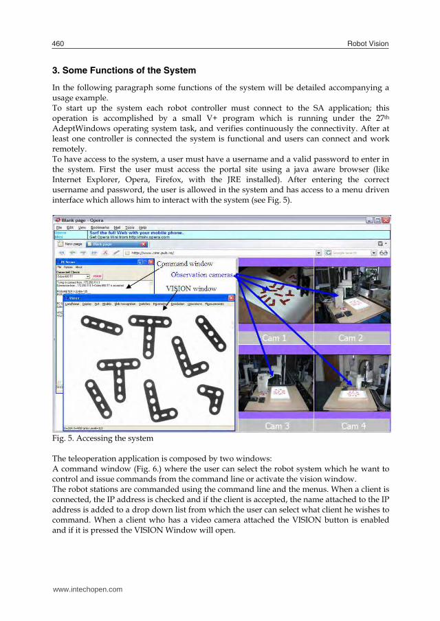
In the following paragraph some functions of the system will be detailed accompanying a usage example. To start up the system each robot controller must connect to the SA application; this operation is accomplished by a small V+ program which is running under the 27th AdeptWindows operating system task, and verifies continuously the connectivity. After at least one controller is connected the system is functional and users can connect and work remotely. To have access to the system, a user must have a username and a valid password to enter in the system. First the user must access the portal site using a java aware browser (like Internet Explorer, Opera, Firefox, with the JRE installed). After entering the correct username and password, the user is allowed in the system and has access to a menu driven interface which allows him to interact with the system (see Fig. 5).
Fig. 5. Accessing the system The teleoperation application is composed by two windows: A command window (Fig. 6.) where the user can select the robot system which he want to control and issue commands from the command line or activate the vision window. The robot stations are commanded using the command line and the menus. When a client is connected, the IP address is checked and if the client is accepted, the name attached to the IP address is added to a drop down list from which the user can select what client he wishes to command. When a client who has a video camera attached the VISION button is enabled and if it is pressed the VISION Window will open.
www.intechopen.com
Remote Robot Vision Control of a Flexible Manufacturing Cell 461
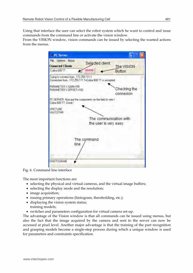
Using that interface the user can select the robot system which he want to control and issue commands from the command line or activate the vision window. From the VISION window, vision commands can be issued by selecting the wanted actions from the menus.
Fig. 6. Command line interface The most important functions are: selecting the physical and virtual cameras, and the virtual image buffers; selecting the display mode and the resolution; image acquisition; issuing primary operations (histogram, thresholding, etc.); displaying the vision system status;
training models; switches and parameters configuration for virtual camera set-up.
The advantage of the Vision window is that all commands can be issued using menus, but also the fact that the image acquired by the camera and sent to the server can now be accessed at pixel level. Another major advantage is that the training of the part recognition and grasping models become a single-step process during which a unique window is used for parameters and constraints specification.
www.intechopen.com
Robot Vision462
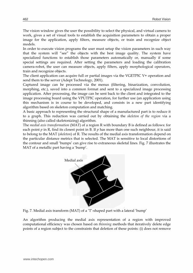
The vision window gives the user the possibility to select the physical, and virtual camera to work, gives a set of visual tools to establish the acquisition parameters to obtain a proper image for the application, apply filters, measure objects, or train and recognize object models. In order to execute vision programs the user must setup the vision parameters in such way that the system will “see” the objects with the best image quality. The system have specialized functions to establish those parameters automatically or, manually if some special settings are required. After setting the parameters and loading the calibration camera-robot, the user can measure objects, apply filters, apply morphological operators, train and recognize objects. The client application can acquire full or partial images via the VGETPIC V+ operation and send them to the server (Adept Technology, 2001). Captured image can be processed via the menus (filtering, binarization, convolution, morphing, etc.), saved into a common format and sent to a specialized image processing application. After processing, the image can be sent back to the client and integrated to the image processing board using the VPUTPIC operation, for further use (an application using this mechanism is in course to be developed, and consists in a new part identifying algorithm based on skeleton computation and matching. A basic approach to representing the structural shape of a manufactured part is to reduce it to a graph. This reduction was carried out by obtaining the skeleton of the region via a thinning (also called skeletonizing) algorithm. The medial axis transformation (MAT) of a region R with boundary B is defined as follows: for each point p in R, find its closest point in B. If p has more than one such neighbour, it is said to belong to the MAT (skeleton) of R. The results of the medial axis transformation depend on the particular distance metrics that is selected. The MAT is sensitive to local distortions of the contour and small ‘bumps’ can give rise to extraneous skeletal lines. Fig. 7 illustrates the MAT of a metallic part having a ‘bump’.
Fig. 7. Medial axis transform (MAT) of a ‘T’-shaped part with a lateral ‘bump’ An algorithm producing the medial axis representation of a region with improved computational efficiency was chosen based on thinning methods that iteratively delete edge points of a region subject to the constraints that deletion of these points: (i) does not remove
Medial axis ‘Bump’
www.intechopen.com

Remote Robot Vision Control of a Flexible Manufacturing Cell 463
end points; (ii) does not break connectedness; (iii) does not cause excessive erosion of the region (Borangiu, 2004), (Borangiu et al., 2005). Binary region points were assumed to have value 1 and background points to have value 0. Successive passes of two basic steps were applied to the contour points of the given region, where a contour point is any pixel of value 1 and having at least one 8-neighbour valued 0. Fig. 8 shows the definition adopted for the 8-neighbourhood.
Fig. 8. Definition (left) and example (right) of the 8 neighbourhood for blob thinning STEP 1. A contour point p is flagged for deletion if the following conditions hold:
1.1 6)(2 1 pN ; 1.2 1)( 1 pS ; 1.3 0642 ppp ; 1.4 0864 ppp ,
(1)
where )( 1pN is the number of nonzero neighbours of 1p , i.e. 9
21)(
iippN , and )( 1pS is
the number of 10 transitions in the ordered sequence of the bits 9832 , ..., , , pppp . For the example in Figure 7, 4)( 1 pN and 2)( 1 pS . Step 1 is applied to every contour point in the binary region of interest. If one or more of conditions )4.1()1.1( are violated, the value of the respective point is not changed. However, the point is not deleted until all contour points have been processed, which prevents changing the structure of the data during execution of the algorithm. After applying step 1 to all border points, those which were flagged are deleted (changed to 0). STEP 2. A contour point p is flagged for deletion if the following conditions hold:
2.1 6)(2 1 pN ; 2.2 1)( 1 pS ; 2.3 0842 ppp ; 2.4 0862 ppp .
(2)
Step 2 is applied to data resulting from step 1 in exactly the same manner. After step 2 has been applied to all border points, those that were flagged are deleted (changed from 1 to 0). Thus one iteration of the thinning algorithm consists of: 1. Applying step 1 to flag contour points for deletion. 2. Deleting the point flagged in step 1.
9p 2p 3p
8p 1p 4p
7p 6p 5p
0 1 1
0 1p 0
1 1 0
www.intechopen.com
Robot Vision464
3. Applying step 2 to flag the remaining contour points for deletion. 4. Deleting the points flagged in step 2. This basic cycle is applied iteratively until no further points were deleted, at which time the algorithm terminates yielding the skeleton of the region. Such types of applications for which the complexity of the computation is very high were developed on a powerful IBM xSeries server instead of the robot vision controller. The skeleton computation is included in the measurements category (Borangiu, et al., 2005) which include also signature analysis, polar and linear offset signatures which are computed, and stored to be used in other applications (see sections 4, 5 and 6). An important feature of the system is the mechanism of training object models and multiple grasping positions related to each model in order to accomplish a collision free grasping position on the runtime. The training of object models can be done in two wais: first is the standard ObjectFinder model, which is computed by the vision board
included in the system. The procedure to train such a model requires a set of steps which have been compacted in a single form in the application.
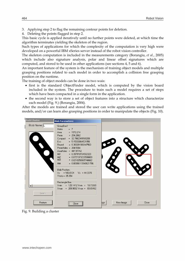
the second way is to store a set of object features into a structure which characterize each model (Fig. 9.) (Borangiu, 2004).
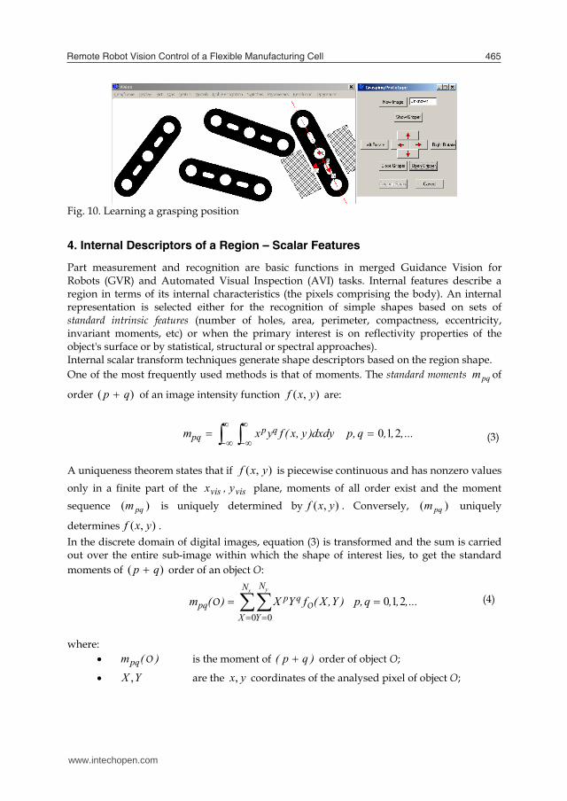
After the models are trained and stored the user can write applications using the trained models, and/or can learn also grasping positions in order to manipulate the objects (Fig. 10).
Fig. 9. Building a cluster
www.intechopen.com
Remote Robot Vision Control of a Flexible Manufacturing Cell 465
Fig. 10. Learning a grasping position
4. Internal Descriptors of a Region – Scalar Features
Part measurement and recognition are basic functions in merged Guidance Vision for Robots (GVR) and Automated Visual Inspection (AVI) tasks. Internal features describe a region in terms of its internal characteristics (the pixels comprising the body). An internal representation is selected either for the recognition of simple shapes based on sets of standard intrinsic features (number of holes, area, perimeter, compactness, eccentricity, invariant moments, etc) or when the primary interest is on reflectivity properties of the object's surface or by statistical, structural or spectral approaches). Internal scalar transform techniques generate shape descriptors based on the region shape. One of the most frequently used methods is that of moments. The standard moments pqm of
order )( qp of an image intensity function ),( yxf are:
...,,,q,pdxdy)y,x(fyxm qp
pq 2 1 0 (3)
A uniqueness theorem states that if ),( yxf is piecewise continuous and has nonzero values only in a finite part of the visvis y,x plane, moments of all order exist and the moment sequence )( pqm is uniquely determined by ),( yxf . Conversely, )( pqm uniquely
determines ),( yxf . In the discrete domain of digital images, equation (3) is transformed and the sum is carried out over the entire sub-image within which the shape of interest lies, to get the standard moments of )( qp order of an object O:
x yN
X
N
Y
qppq ...,,,q,p)Y,X(fYX)(m
0 0 2 1 0 OO
(4)
where:
)(mpq O is the moment of )qp( order of object O;
YX , are the yx, coordinates of the analysed pixel of object O;
www.intechopen.com
Robot Vision466
OO
O object tobelonging pixel ,1object tobelongingnot pixel ,0
),( YXf
yx NN , are the maximum values respectively for the YX , image
coordinates, e.g. 480 ,640 yx NN .
However, because these moments are computed on the basis of the absolute position of the shape, they will vary for a given shape O depending on its location. To overcome this drawback, one can use the central moments of order )( qp :
x yN
X
N
Y
qppq qpYXfYYXX
0 0
... ,2 ,1 ,0, ),()()()( OO
(5)
where 00010010 / ,/ mmYmmX are the coordinates of the shape's centroid. Thus, these moments take the centroid of the shape as their reference point and hence are position-invariant. For binary images of objects O, 00m is simply computed as the sum of all pixels within the shape. Assuming that a pixel is one unit area then 00m is equivalent to the area of the shape expressed in raw pixels. If the binary image of the object was coded using the run-length coding technique, let us consider that kir , is the thk run of the thi line and that the first run in each row is a run of
zeros. If there are im runs on the thi line, and a total of M lines in the image, the area can be computed as the sum of the run lengths corresponding to ones in the image:
M
i
m
kki
i
rmArea1
2/
12,00 )()( OO
(6)
Note that the sum is over the even runs only. Similarly, 10m and 01m are effectively obtained respectively by the summation of all the x-coordinates and y-coordinates of pixels in the shape. The central moments up to order three are given as expressed in (7):
0000 m 101111 mYm
010 102
203030 23 mXmXm
001 012
020303 23 mYmYm
102020 mXm 102
02111212 22 mYmXmYm
010202 mYm 012
20112121 22 mXmYmXm
(7)
www.intechopen.com
Remote Robot Vision Control of a Flexible Manufacturing Cell 467
The central moments can be normalized, defining a set of normalized central moments,
pq , and having the expression kpqpq )(/)()( 00 OOO , where
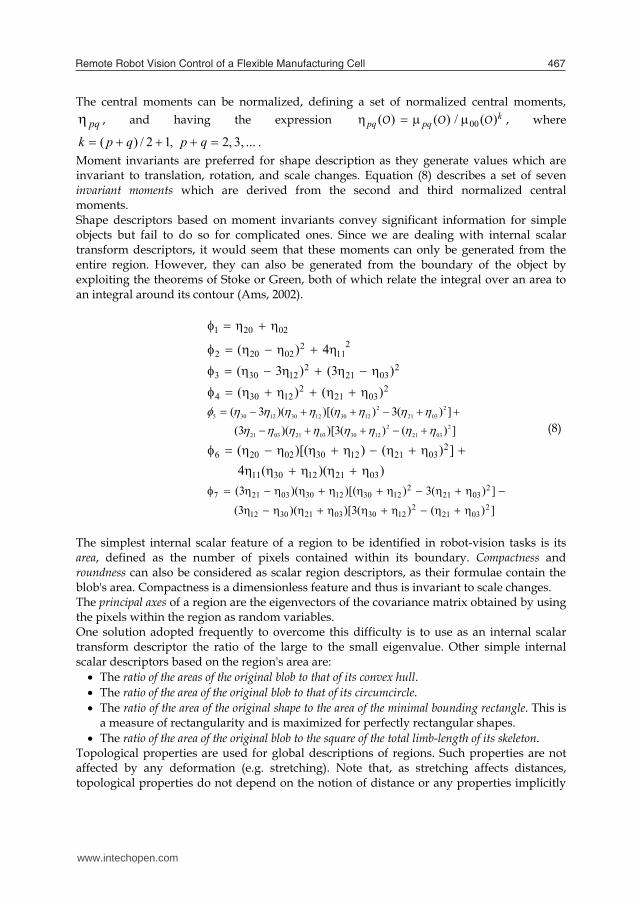
... 3, ,2 ,12/)( qpqpk . Moment invariants are preferred for shape description as they generate values which are invariant to translation, rotation, and scale changes. Equation (8) describes a set of seven invariant moments which are derived from the second and third normalized central moments. Shape descriptors based on moment invariants convey significant information for simple objects but fail to do so for complicated ones. Since we are dealing with internal scalar transform descriptors, it would seem that these moments can only be generated from the entire region. However, they can also be generated from the boundary of the object by exploiting the theorems of Stoke or Green, both of which relate the integral over an area to an integral around its contour (Ams, 2002).
02201 2
112
02202 4)( 2
03212
12303 )3()3( 2
03212
12304 )()( ])()(3)[)((3
])(3))[()(3(2
03212
123003210321
20321
21230123012305
))((4 ])())[((
0321123011
20321123002206
])()(3)[)((3
])(3))[()(3(2
03212
123003213012
20321
21230123003217
(8)
The simplest internal scalar feature of a region to be identified in robot-vision tasks is its area, defined as the number of pixels contained within its boundary. Compactness and roundness can also be considered as scalar region descriptors, as their formulae contain the blob's area. Compactness is a dimensionless feature and thus is invariant to scale changes. The principal axes of a region are the eigenvectors of the covariance matrix obtained by using the pixels within the region as random variables. One solution adopted frequently to overcome this difficulty is to use as an internal scalar transform descriptor the ratio of the large to the small eigenvalue. Other simple internal scalar descriptors based on the region's area are: The ratio of the areas of the original blob to that of its convex hull. The ratio of the area of the original blob to that of its circumcircle. The ratio of the area of the original shape to the area of the minimal bounding rectangle. This is
a measure of rectangularity and is maximized for perfectly rectangular shapes. The ratio of the area of the original blob to the square of the total limb-length of its skeleton.
Topological properties are used for global descriptions of regions. Such properties are not affected by any deformation (e.g. stretching). Note that, as stretching affects distances, topological properties do not depend on the notion of distance or any properties implicitly
www.intechopen.com
Robot Vision468
based on the concept of distance measure. A widely used topological descriptor is the number of holes in the region, which is not affected by stretching or rotation transformations (Fogel, 1994; Ghosh, 1988). The number of holes H and connected components C in a region can be used to define another topological feature – the Euler number E of a region:
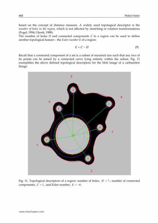
HCE (9) Recall that a connected component of a set is a subset of maximal size such that any two of its points can be joined by a connected curve lying entirely within the subset. Fig. 11 exemplifies the above defined topological descriptors for the blob image of a carburettor flange:
Fig. 11. Topological descriptors of a region: number of holes, 7H , number of connected components, 1C , and Euler number, 6E .
www.intechopen.com

Remote Robot Vision Control of a Flexible Manufacturing Cell 469
5. Space Domain Descriptors of Boundaries: The Signatures
External space domain features describe the spatial organization of the object's boundary. One frequently used technique is the use of syntactic descriptors of boundary primitives, e.g. atomic edges (lines and arcs), and corners. Thus, the list of shape descriptors (or string of primitive shapes) must follow given rules: the shape syntax or grammar. Signatures are 1-D functional representations of boundaries and may be generated in various ways, for example as polar radii signatures or linear offset signatures. Regardless of how a signature is generated, however, the main idea approached in the present research devoted to real-time visual analysis of parts handled by robots is to reduce the boundary representation to a 1-D function, which is easier to describe than the original 2-D boundary (Borangiu and Calin, 1996; Camps, et al., 1991). A polar radii signature, encoding the distance from the shape centroid to the shape boundary as a function of angle , is shown in Fig. 12.
Fig. 12. Angular radii signature of a shape. A 15-element vector ],...,,[ 1521 RRR is defined, where 15,...,1 , iRi is the distance from the centroid to the edge of the blob, measured at an angle of )24( 0 i degrees, and 0 is the orientation derived from the greatest radius, 1R
Distance [mm]
Angle
13R
14R
7R
4R
3R1R
2R
5R
6R
8R 9R
10R 11R 12R
15R
Maximum radius
0
0152
154
1528 2
www.intechopen.com
Robot Vision470
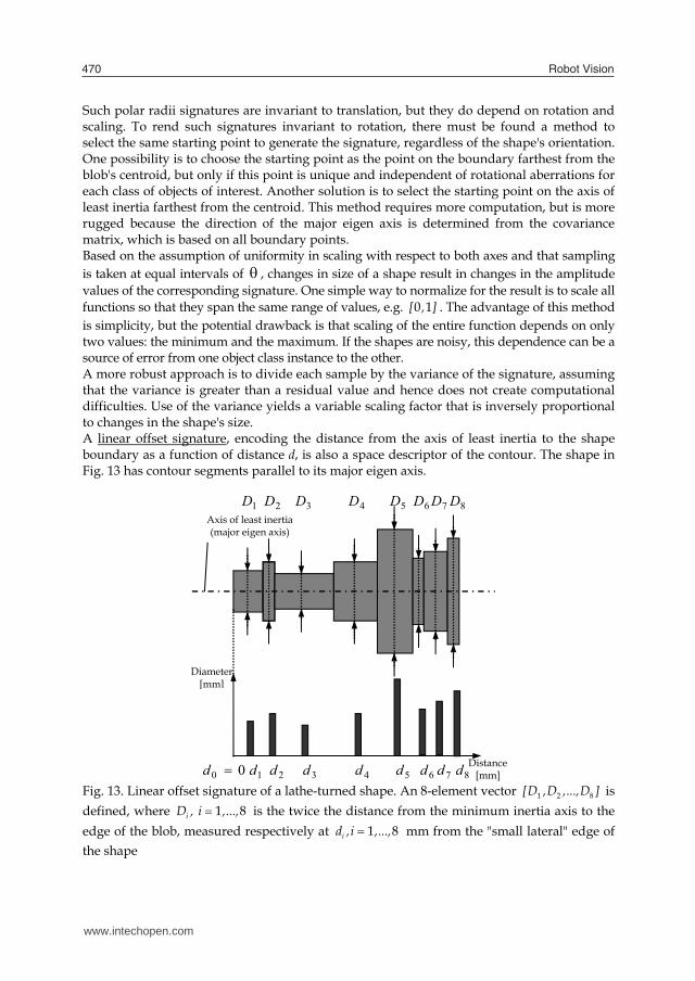
Such polar radii signatures are invariant to translation, but they do depend on rotation and scaling. To rend such signatures invariant to rotation, there must be found a method to select the same starting point to generate the signature, regardless of the shape's orientation. One possibility is to choose the starting point as the point on the boundary farthest from the blob's centroid, but only if this point is unique and independent of rotational aberrations for each class of objects of interest. Another solution is to select the starting point on the axis of least inertia farthest from the centroid. This method requires more computation, but is more rugged because the direction of the major eigen axis is determined from the covariance matrix, which is based on all boundary points. Based on the assumption of uniformity in scaling with respect to both axes and that sampling is taken at equal intervals of , changes in size of a shape result in changes in the amplitude values of the corresponding signature. One simple way to normalize for the result is to scale all functions so that they span the same range of values, e.g. [ , ]0 1 . The advantage of this method is simplicity, but the potential drawback is that scaling of the entire function depends on only two values: the minimum and the maximum. If the shapes are noisy, this dependence can be a source of error from one object class instance to the other. A more robust approach is to divide each sample by the variance of the signature, assuming that the variance is greater than a residual value and hence does not create computational difficulties. Use of the variance yields a variable scaling factor that is inversely proportional to changes in the shape's size. A linear offset signature, encoding the distance from the axis of least inertia to the shape boundary as a function of distance d, is also a space descriptor of the contour. The shape in Fig. 13 has contour segments parallel to its major eigen axis.
Fig. 13. Linear offset signature of a lathe-turned shape. An 8-element vector [D ,D ,...,D ]1 2 8 is defined, where iD , i ,..., 1 8 is the twice the distance from the minimum inertia axis to the edge of the blob, measured respectively at id ,i ,..., 1 8 mm from the "small lateral" edge of the shape
1D 2D 3D 4D 5D 6D 7D 8D
Axis of least inertia (major eigen axis)
2d1d 3d 4d 5d 6d 7d 8d
Diameter [mm]
Distance[mm] 00 d
www.intechopen.com
Remote Robot Vision Control of a Flexible Manufacturing Cell 471
It can be observed that in this case sampling is not taken at equal intervals of d , i.e. 8 ..., 1, const,1 idd ii .
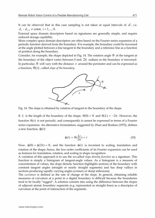
External space domain descriptors based on signatures are generally simple, and require reduced storage capability. More complex space domain descriptors are often based on the Fourier series expansion of a periodic function derived from the boundary. For example, the boundary could be traversed at the angle plotted between a line tangent to the boundary and a reference line as a function of position along the boundary. Consider, for example, the shape depicted in Fig. 14. The rotation angle of the tangent at the boundary of the object varies between 0 and 2 radians as the boundary is traversed. In particular, will vary with the distance s around the perimeter and can be expressed as a function, )(s , called slope of the boundary.
Fig. 14. The slope is obtained by rotation of tangent to the boundary of the shape If L is the length of the boundary of the shape, 0)0( and 2)(L . However, the function )(s is not periodic, and consequently it cannot be expressed in terms of a Fourier series expansion. An alternative formulation, suggested by Zhan and Roskies (1972), defines a new function, )(t :
tLtt )2()( (10)
Now, 0)2()0( , and the function )(t is invariant to scaling, translation and rotation of the shape; hence, the low-order coefficients of its Fourier expansion can be used as features for translation, rotation, and scaling in shape recognition. A variation of this approach is to use the so-called slope density function as a signature. This function is simply a histogram of tangent-angle values. As a histogram is a measure of concentration of values, the slope density function highlights sections of the boundary with constant tangent angles (straight or nearly straight segments) and has deep valleys in sections producing rapidly varying angles (corners or sharp inflexions). The curvature is defined as the rate of change of the slope. In general, obtaining reliable measures of curvature at a point in a digital boundary is difficult because the boundaries tend to be locally "ragged". A solution consists into using the difference between the slopes of adjacent atomic boundary segments (e.g. represented as straight lines) as a descriptor of curvature at the point of intersection of the segments.
s
www.intechopen.com
Robot Vision472
6. Experimental Results for Signature Analysis
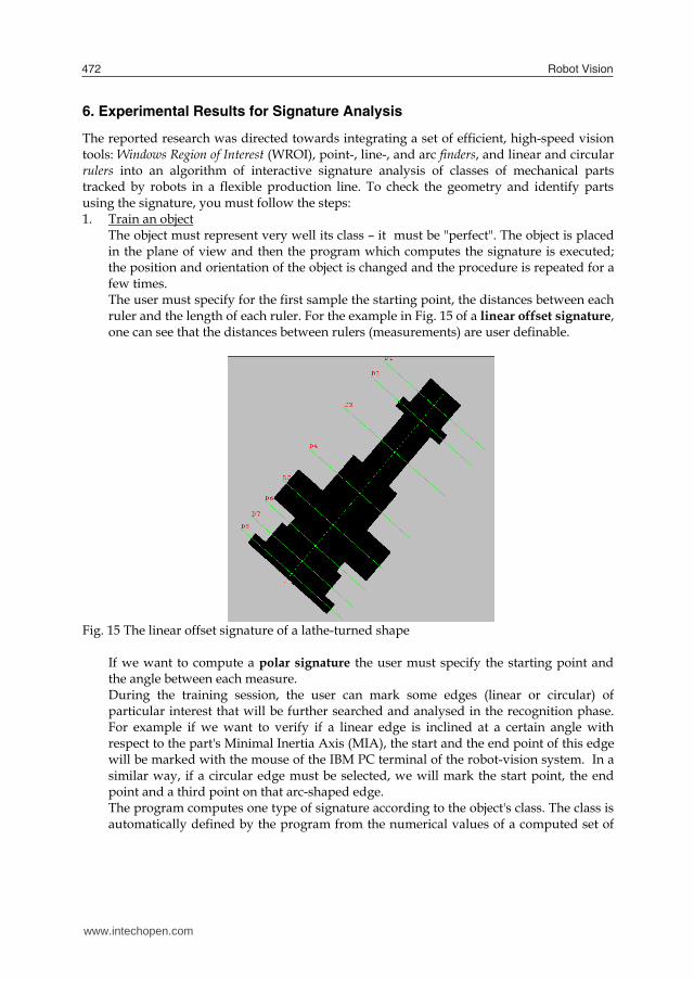
The reported research was directed towards integrating a set of efficient, high-speed vision tools: Windows Region of Interest (WROI), point-, line-, and arc finders, and linear and circular rulers into an algorithm of interactive signature analysis of classes of mechanical parts tracked by robots in a flexible production line. To check the geometry and identify parts using the signature, you must follow the steps: 1. Train an object
The object must represent very well its class – it must be "perfect". The object is placed in the plane of view and then the program which computes the signature is executed; the position and orientation of the object is changed and the procedure is repeated for a few times. The user must specify for the first sample the starting point, the distances between each ruler and the length of each ruler. For the example in Fig. 15 of a linear offset signature, one can see that the distances between rulers (measurements) are user definable.
Fig. 15 The linear offset signature of a lathe-turned shape
If we want to compute a polar signature the user must specify the starting point and the angle between each measure. During the training session, the user can mark some edges (linear or circular) of particular interest that will be further searched and analysed in the recognition phase. For example if we want to verify if a linear edge is inclined at a certain angle with respect to the part's Minimal Inertia Axis (MIA), the start and the end point of this edge will be marked with the mouse of the IBM PC terminal of the robot-vision system. In a similar way, if a circular edge must be selected, we will mark the start point, the end point and a third point on that arc-shaped edge. The program computes one type of signature according to the object's class. The class is automatically defined by the program from the numerical values of a computed set of
www.intechopen.com
Remote Robot Vision Control of a Flexible Manufacturing Cell 473
standard scalar internal descriptors: compactness, eccentricity, roundness, invariant moments, number of bays, a.o. After the training the object has associated a class, a signature, a name and two parameters: the tolerance and the percentage of verification.
2. Setting the parameters used for recognition The tolerance: each measure of the recognized object must be into a range: (original measure ± the tolerance value). The tolerance can be modified anytime by the user and will be applied at run time by the application program. The percentage of verification: specifies how many measures can be out of range (100% – every measure must be in the range, 50% – the maximum number of rulers that can be out of range is ½ of the total number). The default value of the percentage of verification proposed by the application is 95%.
3. The recognition stage The sequence of operations used for measuring and recognition of mechanical parts includes: taking a picture, computation of the class to which the object in the WROI belongs, and finally applying the associated set of vision tools to evaluate the particular signature for all trained objects of this class. The design of the signature analysis program has been performed using specific vision tools on an Adept Cobra 600 TT robot, equipped with a GP-MF602 Panasonic camera and AVI vision processor. The length measurements were computed using linear rulers (VRULERI), and checking for the presence of linear and circular edges was based respectively on the finder tools VFIND.ARC and VFIND.LINE (Adept, 2001).
The pseudo-code below summarizes the principle of the interactive learning during the training stage and the real time computation process during the recognition stage.
i) Training 1. Picture acquisition 2. Selecting the object class (from the computed values of internal descriptors:
compactness, roundness,...) 3. Suggesting the type of signature analysis:
Linear Offset Signature (LOF) specify the starting point and the linear offsets
Polar Signature (PS) specify the starting point and the incremental angle
4. Specify the particular edges to be verified 5. Improve the measurements?
Compute repeatedly only the signature (the position of the object is changed every time)
Update the mean value of the signature. 6. Compute the recognition parameters (tolerance, percentage of verification) and name
the learned model. 7. Display the results and terminate the training sequence.
www.intechopen.com

Robot Vision474
ii) Run time measurement and recognition 1. Picture acquisition 2. Identifying the object class (using the compactness, roundness,... descriptors) 3. Computing the associated signature analysis for each class model trained. 4. Checking the signature against its trained value, and inspecting the particular edges (if
any) using finder and ruler tools 5. Returning the results to the AVI program or GVR robot motion planner (the name of
the recognized object, or void). 6. Updating the reports about inspected and/or manipulated (assembled) parts;
sequence terminated. Fig. 16 and Table 1 show the results obtained for a polar signature of a leaf-shaped object.
Fig. 16. Computing the polar signature of a blob
Parameter
Min value( min )
Max value ( max )
Mean value( avg )
Dispersion( disp )
Number of ruler tools
used 1R 68.48 70.46 68.23 1.98 1 2R 56.59 58.44 57.02 1.85 1 3R 26.68 28.42 27.41 1.74 1
4R 32.24 34.03 33.76 1.52 1 5R 44.82 45.92 45.42 1.10 1
6R 54.07 55.92 54.83 1.85 1
7R 51.52 52.76 52.05 1.24 1
8R 50.39 51.62 50.98 1.23 1
9R 49.15 51.18 49.67 2.03 1
RA 25.41 26.98 26.22 1.57 1 RB 47.41 48.68 47.91 1.27 1 RC 53.71 55.30 54,64 1.59 1
RD 57.79 59.51 58.61 1.72 1 RE 35.69 37.39 36.80 1.70 1 RF 35.42 36.72 36.17 1.30 1
Table 1. Statistical results for the polar radii signature of the leaf-shaped object
www.intechopen.com
Remote Robot Vision Control of a Flexible Manufacturing Cell 475
The dispersion was calculated for each parameter 101 ,...,i,Pi as: )Pmin()Pmax()P(disp iii , and is expressed in the same units as the parameter
(millimetres or degrees). The min/max values are: )Pmin(min i , )Pmax(max i . The
expression of the mean value is: i
iPavg101 .
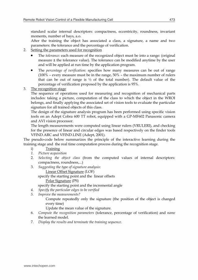
7. The Supervising Function
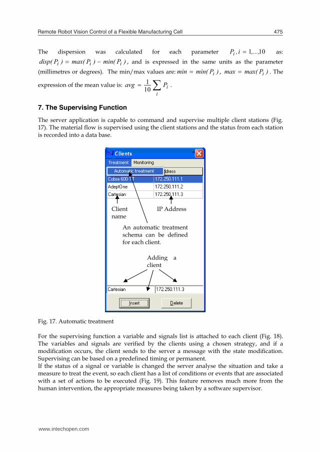
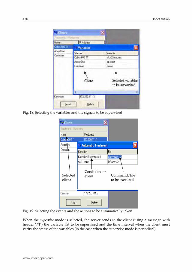
The server application is capable to command and supervise multiple client stations (Fig. 17). The material flow is supervised using the client stations and the status from each station is recorded into a data base. Fig. 17. Automatic treatment For the supervising function a variable and signals list is attached to each client (Fig. 18). The variables and signals are verified by the clients using a chosen strategy, and if a modification occurs, the client sends to the server a message with the state modification. Supervising can be based on a predefined timing or permanent. If the status of a signal or variable is changed the server analyse the situation and take a measure to treat the event, so each client has a list of conditions or events that are associated with a set of actions to be executed (Fig. 19). This feature removes much more from the human intervention, the appropriate measures being taken by a software supervisor.
Adding aclient
Client name
An automatic treatmentschema can be definedfor each client.
IP Address
www.intechopen.com
Robot Vision476
Fig. 18. Selecting the variables and the signals to be supervised Fig. 19. Selecting the events and the actions to be automatically taken When the supervise mode is selected, the server sends to the client (using a message with header ‘/T’) the variable list to be supervised and the time interval when the client must verify the status of the variables (in the case when the supervise mode is periodical).
Selected client
Condition orevent Command/file
to be executed
www.intechopen.com
Remote Robot Vision Control of a Flexible Manufacturing Cell 477
The events which trigger response actions can be produced by reaction programs run by the controller (REACTI or REACTE type) or by special user commands from the terminal. The list of actions contains direct commands for the robot (ABORT, KILL 0, DETACH, etc) and program execution commands (EXECUTE, CALL).
8. Conclusions
The project was finished at the end of 2008 as part of the PRIC research program (Shared Research and Training Resources). The research project provide a communication and collaboration portal solution for linking the existing pilot platform with multiple V+ industrial robot-vision controllers from Adept Technology located in four University Labs from Romania (Bucharest, Craiova, Iasi and Galati). This allow teachers to train their student using robots and expensive devices which they do not dispose, and allow students to practice their skills using specialised labs without geographical barriers, and even from home. Also the portal will allow team training and research due to the messaging feature introduced by Domino. The fault tolerance solution presented in this paper is worth to be considered in environments where the production structure has the possibility to reconfigure, and where the manufacturing must assure a continuous production flow at batch level (job shop flow). The spatial layout and configuring of robots must be done such that one robot will be able to take the functions of another robot in case of failure. If this involves common workspaces, programming must be made with much care using robot synchronizations and monitoring continuously the current position of the manipulator. The advantages of the proposed solution are that the structure provides a high availability robotized work structure with an insignificant downtime due to the automated monitoring and treatment function. In some situations the solution could be considered as a fault tolerant system due to the fact that even if a robot controller failed, the production can continue in normal conditions by triggering and treating each event using customized functions. The project can be accessed at: http://pric.cimr.pub.ro.
9. References
Adept Technology Inc., (2001). AdeptVision Reference Guide Version 14.0 Part Number 00964-03000, San Jose, Technical Publications.
Ams, E. (2002). Eine für alles ?, Computer & Automation, No. 5, pp. 22-25. Anton F., D., Borangiu, Th., Tunaru, S., Dogar, A., and S. Gheorghiu. (2006). Remote
Monitoring and Control of a Robotized Fault Tolerant Workcell, Proc. of the 12th IFAC Sympos. on Information Control Problems in Manufacturing INCOM'06, Elsevier.
Borangiu, TH. and L. Calin (1996). Task Oriented Programming of Adaptive Robots and Integration in Fault–Tolerant Manufacturing Systems, Proc. of the Int. Conf. on Industrial Informatics, Section 4 Robotics, Lille, pp. 221-226.
Borangiu, Th., (2004). Intelligent Image Processing in Robotics and Manufacturing, Romanian Academy Press, Bucharest.
www.intechopen.com
Robot Vision478
Borangiu, Th., F.D. Anton, S. Tunaru and N.-A. Ivanescu, (2005). Integrated Vision Tools And Signature Analysis For Part Measurement And Recognition In Robotic Tasks, IFAC World Congress, Prague.
Borangiu, Th., Anton F., D., Tunaru, S., and A. Dogar. (2006). A Holonic Fault Tolerant Manufacturing Platform with Multiple Robots, Proc. of 15th Int. Workshop on Robotics in Alpe-Adria-Danube Region RAAD 2006.
Brooks, K., R. Dhaliwal, K. O’Donnell, E. Stanton, K. Sumner and S. Van Herzele, (2004). Lotus Domino 6.5.1 and Extended Products Integration Guide, IBM RedBooks.
Camps, O.I., L.G. Shapiro and R.M. Harlick (1991). PREMIO: An overview, Proc. IEEE Workshop on Directions in Automated CAD-Based Vision, pp. 11-21.
Fogel, D.B. (1994). Evolutionary Computation: Toward a New Philosophy of Machine Intelligence, IEEE Press, New York.
Ghosh, P. (1988). A mathematical model foe shape description using Minkowski operators, Computer Vision Graphics Image Processing, 44, pp. 239-269.
Harris, N., Armingaud, F., Belardi, M., Hunt, C., Lima, M., Malchisky Jr., W., Ruibal, J., R. and J. Taylor, (2004). Linux Handbook: A guide to IBM Linux Solutions and Resources, IBM Int. Technical Support Organization, 2nd Edition.
Tomas Balibrea, L.M., L.A. Gonzales Contreras and M. Manu (1997). Object Oriented Model of an Open Communication Architecture for Flexible Manufacturing Control, Computer Science 1333 - Computer Aided System Theory, pp. 292-300, EUROCAST ’97, Berlin.
Zhan, C.T. and R.Z. Roskies (1972). Fourier descriptors for plane closed curves, IEEE Trans. Computers, Vol. C-21, pp. 269-281.
www.intechopen.com
Robot VisionEdited by Ales Ude
ISBN 978-953-307-077-3Hard cover, 614 pagesPublisher InTechPublished online 01, March, 2010Published in print edition March, 2010
InTech EuropeUniversity Campus STeP Ri Slavka Krautzeka 83/A 51000 Rijeka, Croatia Phone: +385 (51) 770 447 Fax: +385 (51) 686 166www.intechopen.com
InTech ChinaUnit 405, Office Block, Hotel Equatorial Shanghai No.65, Yan An Road (West), Shanghai, 200040, China
Phone: +86-21-62489820 Fax: +86-21-62489821
The purpose of robot vision is to enable robots to perceive the external world in order to perform a large rangeof tasks such as navigation, visual servoing for object tracking and manipulation, object recognition andcategorization, surveillance, and higher-level decision-making. Among different perceptual modalities, vision isarguably the most important one. It is therefore an essential building block of a cognitive robot. This bookpresents a snapshot of the wide variety of work in robot vision that is currently going on in different parts of theworld.
How to referenceIn order to correctly reference this scholarly work, feel free to copy and paste the following:
Silvia Anton, Florin Daniel Anton and Theodor Borangiu (2010). Remote Robot Vision Control of a FlexibleManufacturing Cell, Robot Vision, Ales Ude (Ed.), ISBN: 978-953-307-077-3, InTech, Available from:http://www.intechopen.com/books/robot-vision/remote-robot-vision-control-of-a-flexible-manufacturing-cell

© 2010 The Author(s). Licensee IntechOpen. This chapter is distributedunder the terms of the Creative Commons Attribution-NonCommercial-ShareAlike-3.0 License, which permits use, distribution and reproduction fornon-commercial purposes, provided the original is properly cited andderivative works building on this content are distributed under the samelicense.