Embed Size (px)
Citation preview

Journal of the Optical Society of KoreaVol. 12, No. 3, September 2008, pp. 166-169
- 166 -
DOI: 10.3807/JOSK.2008.12.3.166
Remote Monitoring of Abrupt Overflowing in Common Utility Duct Using Reflective Side-Polished Optical Fiber
Submersion Sensor
Cherl-Hee Lee and Cheol Kim*
School of Mechanical Engineering, Kyungpook National University, 702-701, Korea
Shin-Won Kang and Jae-Won Song
School of Electrical Engineering and Computer Science, Kyungpook National University, 702-701, Korea
(Received July 14, 2008 : revised August 12, 2008 : accepted August 12, 2008)
The submersion monitoring system based on a reflective side-polished optical fiber submersion sensor with an optical fiber mirror was shown to be an effective alarm system with remote monitoringwhen the drainage capacity of a common utility duct is exceeded due to heavy rainfall. The proposed sensor was connected to an existing installed optical fiber network at a height of 250mm in a common utility duct, and then tested under sample materials (distilled water, river water, sea water, foul water, muddy water, petroleum, edible oil) at a distance of 1km from the sensor for remote sensing. In experiments, the proposed real-time sensor system reduced maintenance cost and improved monitoring efficiency by using a reflection-type side-polished optical fiber submersion sensor efficient for remote monitoring of a common utility duct.
Keywords : common utility duct, submersion sensor, abrupt overflowing, side-polished, remote sensing
OCIS codes : (240.5450) Polishing ; (060.2370) Fiber optics sensors ; (060.0060) Fiber optics and optical communications ; (060.4510) Optical communications ; (120.0280) Remote sensing
*Corresponding author: [email protected]
I. INTRODUCTION
A common utility duct is a structure, above or under ground, which contains all the major utilities in one common duct. Multiple lines for phones, electricity, gas, cable TV, fiber optics, traffic signals, street lighting circuits, drainage and flood control facilities, water mains and waste water pipes are dispersed to-gether through an underground pathway of conduits linked by common utility ducts, as shown in Fig. 1.
The advantages for cities and towns to adopt such a system include maximizing the efficiency of under-ground ground space usage, decreasing the costs of main-taining manholes, decreasing above-ground construction that can disrupt traffic, and creating an area for easy access to repair utilities. Plus, a common utility duct
should also incorporate its own drainage, ventilation, lighting, communication, power, monitoring systems, and so on. Common utility ducts need to be remote- monitored using sensors to gather information and controlled by a management system for emergency treat-ment to prevent fires, power-failures, and flooding. The monitored data, such as the temperature, uplift, and submersion also needs to be gathered in real-time and applied for system control.
Every year, floods and localized torrential downpours cause extensive damage to underground facilities, such as common utility ducts, in many countries. However, despite protective measures to protect common utility ducts from water intrusion, their location and physical characteristics make this very difficult as water can still penetrate through entrances, ventilating openings, and equipment gateways. Yet, if moisture enters an electrical cable or spliced cable, this can quickly lead

Remote Monitoring of Abrupt Overflowing in Common Utility Duct Using … - Cheol Kim et al. 167
FIG. 1. Side-view of common utility duct.
to permanent physical damage and potential multiple service outages, such as power-failures and electric leakages. Plus, if moisture enters many splice enclosures in an optical fiber network, this can have a detrimental effect on the service quality of a communication net-work and shorten its lifetime. Thus, a feed pond and drainage pump need to be installed in a common utility duct, where any intruding water is guided to the feed pond via waterways dug in the floor, and then bailed out using the drainage pump controlled by a level sensor installed in the feed pond. In addition, to deal with he-avy rainfall above drainage capacity, submerged locations need to be detected by a submersion sensor and re-stored to normal conditions as quickly as possible. Com-mon utility ducts support the major underground com-ponent of the public communication networks, including the optical fiber cables supporting the backbone of net-work architectures.
To monitor the submersion, various water sensors have been developed using optical fiber bending [1], hydrogel fiber [2,3] and side-polished fibers [4-6]. The sensors based on the fiber bending and hydrogel fiber use swelling materials. In the water, the materials swell and cause the fiber to be deformed, so the light passing through the sensor suffers bending losses. However, it takes time for the swelling materials to absorb water, so real-time monitoring is difficult and it is also difficult to reuse the swelling materials. Recently, several sub-mersion sensors have been developed using side-polished optical fibers [4-6], which have the advantages of an immediate response, high recurrence, low insertion loss, mechanical stability, and simple fabrication process. Trans-mission-type [4-5] and reflective-type [6] side-polished optical fiber submersion sensors were developed. A reflection-type side-polished optical fiber submersion sen-sor provided efficient remote sensing.
Thus, a reflection-type side-polished optical fiber sub-mersion sensor would be an efficient way to send a sub-mergence alarm if the capacity of the feed pond in a
common utility duct is exceeded due to the inundation of water. The proposed remote submersion monitoring system uses a reflective side-polished optical fiber sub-mersion sensor (RSS), which is spliced with an existing installed optical fiber network in a common utility duct. The monitoring system also utilizes the existing ins-talled optical fiber network in a common utility duct, thereby reducing the installation costs. In addition, the proposed monitoring system can easily determine the height of a water overflow in a common utility duct based on the height of the installed RSS, allowing real- time submersion monitoring. Physically checking a com-mon utility duct is time-consuming and costly, since it involves moving heavy common utility duct lids, pum-ping away any stagnated water, and measuring the ox-ygen density and temperature, etc. As such, using the proposed monitoring system to monitor the water over-flows in a common utility duct could significantly im-prove the monitoring ability and reduce the maintenance expenses. Plus, conventional transmission-type side- polished optical fiber submersion sensors are restricted as regards measuring long distances, as the optical source and detector are required to be at opposite ends of the sensor system making the efficiency and moni-toring costs major barriers to the realization of a practical fiber sensor system. Thus, a submersion monitoring sys-tem using a RSS with an optical fiber mirror serving as a reflector is proposed as more suitable for remote sensing.
The mirror as a reflector is formed at the end surface of a single mode optical fiber (SMF) using a fusion splicing technique [3]. By connecting the optical fiber mirror to one end of the RSS, this allows both the op-tical source and detector to be located at the other end, thereby improving the monitoring efficiency and reducing the maintenance costs. The RSS with an optical fiber mirror can also monitor submersion based on a through-put power gain or resonance wavelength shift. The pro-posed sensor was tested using distilled water and the measurement was made at distance of 1 km from the sensor for remote sensing. The experimental results showed a high sensitivity and confirmed the capability for remote sensing.
II. EXPERIMENTAL RESULTS
Fig. 2 presents the geometry of the RSS. The RSS consists of a side-polished single-mode fiber, evanescently coupled to a multimode planar waveguide overlay (PWG), and an optical fiber mirror. A power exchange between the fiber and the PWG only takes place if the effective index of one of the modes of the PWG is matched to the fiber effective index. In the RSS, the power ex-change occurs twice, as the light goes through the pol-ished region twice due to the optical fiber mirror. Hence,

Journal of the Optical Society of Korea, Vol. 12, No. 3, September 2008168
FIG. 2. Geometry of RSS.
FIG. 3. Experimental setup.
the wavelength response of the RSS shows an approx-imately periodic resonant behavior (band-rejection filter) dependent on the material properties contacting the PWG which changes the effective index of modes of the PWG.
Thus, the different materials contacting on the PWG induce a resonant wavelength shift. The thickness of the residual cladding was approximately 1 μm based on the liquid drip method and 65 μm -thick spacers were placed on the silica block. Plus, a 170 μm -thick microscope cover glass used as the PWG was fixed to the spacers using the NOA 65 (adhesive, Norland) with a refractive index of 1.52. The refractive index of the fiber core, clad, and PWG used in this experiment were 1.450, 1.444, and 1.523, respectively. The optical fiber mirror was made on a piece of cleaved fiber with end surface coating, where the surface coating was fabricated using aluminum deposited on the end of an SMF at a thickness of 2 μm using thermal evaporation with a re-flectance of 72%. The experimental setup is shown in Fig. 3. A wideband erbium amplified spontaneous emis-sion source was used as the light source, and an optical spectrum analyzer used to detect the resonance wave-length shift and throughput power gain of the RSS. An optical circulator with an insertion loss of 0.5 dB and isolation greater than 40 dB for all circulating ports was placed to feed back the source light and used as an output port to measure the optical power and spectra.
The RSS was spliced to an optical fiber network in an optical fiber duct and located at a height of 250 mm. Twofold coupling was obtained due to the transmitted light and to light reflected by the mirror. To confirm the remote abilities, a 1-km-long fiber bundle was in-serted between the RSS and the circulator. Plus, remote sensing with various lengths of fibers can easily be meas-ured using the RSS system.
Fig. 4 shows the experimental results. The solid line represents the transmission of the RSS in air before submersion. A minimal transmission dip due to coupling occurred at 1540 nm, and the minimal transmission was -22.01 dB. The dotted line represents the transmission of the RSS submersed in distilled water. The minimal transmission was -22.02 dB at 1541.6 nm; the coupling wavelength was shifted by about 1.6 nm and the through-put power gain at 1540 nm was 2 dB. The RSS was also tested while varying the humidity from 0 to 85%. The test results revealed no difference in the RSS through-put gain when changing the humidity, indicating that the RSS can detect submersion without being affected by humidity.
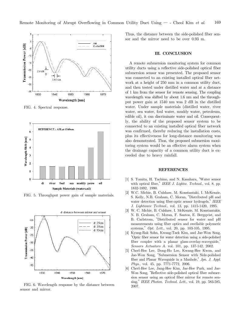
When the RSS is dipped in the different sample ma-terials (distilled water, river water, sea water, foul water, muddy water, petroleum, and edible oil), the wavelength shift was changed by the overlay sample materials, as shown in Fig. 5. The coupling wavelength is shifted 1.6 nm in the water samples, but more than double in the oils. As the refractive index of petroleum is different from that of water, the coupling wavelength of the petroleum is shifted about 4 nm. Thus petroleum and water can easily be discriminated. The RSS clearly ex-hibited a different response to the water samples com-pared to the oil samples, confirming its suitability for application in a submergence monitoring system in a common utility duct.
The distance between the side-polished fiber sensor and the mirror affects the spectral response of the RSS as shown in Fig. 6. The distance between the side-polished fiber sensor and the mirror did have an effect on the spectral response of the RSS, as when the distance was over 0.93 m, the transmission power of the RSS was the same, yet when the distance was below 0.93 m, the trans-mission power of the RSS became lower than 0.93 m.
Remote Monitoring of Abrupt Overflowing in Common Utility Duct Using … - Cheol Kim et al. 169
FIG. 4. Spectral response.
FIG. 5. Throughput power gain of sample materials.
FIG. 6. Wavelength response by the distance between sensor and mirror.
Thus, the distance between the side-polished fiber sen-sor and the mirror need to be over 0.93 m.
III. CONCLUSION
A remote submersion monitoring system for common utility ducts using a reflective side-polished optical fiber submersion sensor was presented. The proposed sensor was connected to an existing installed optical fiber net-work at a height of 250 mm in a common utility duct, and then tested under distilled water and at a distance of 1 km from the sensor for remote sensing. The coupling wavelength was shifted by about 1.6 nm and the through-put power gain at 1540 nm was 2 dB in the distilled water. Under sample materials (distilled water, river water, sea water, foul water, muddy water, petroleum, edible oil), it can discriminate water and oil. Consequent-ly, the ability of the proposed sensor system to be connected to an existing installed optical fiber network was confirmed, thereby reducing the installation costs, plus its effectiveness for long-distance monitoring was also demonstrated. Thus, the proposed submersion moni-toring system would be an effective alarm system when the drainage capacity of a common utility duct is ex-ceeded due to heavy rainfall.
REFERENCES
[1] S. Tomita, H. Tachino, and N. Kasahara, “Water sensor with optical fiber,” IEEE J. Lightw. Technol., vol. 8, pp. 1832-1892, 1990.
[2] W.C. Michie, B. Culshaw, M. Konstantaki, I. McKenzie, S. Kelly, N.B. Graham, C. Moran, “Distributed pH and water detection using fiber-optic sensor hydrogels,” IEEE J. Lightwave Technol., vol. 13, pp. 1415-1420, 1995.
[3] W. C. Michie, B. Culshaw, I. McKenzie, M. Konstantakis, N. B. Graham, C. Moran, F. Santos, E. Bergqvist, and B. Carlstrom, “Distributed sensor for water and pH measurements using fiber optics and swellable polymeric systems,” Opt. Lett., vol. 20, pp. 103-105, 1995.
[4] Kyung-Rak Sohn, Kwang-Taek Kim, and Jae-Won Song, “Optic fiber sensor for water detection using a side-polished fiber coupler with a planar glass-overlay-waveguide,” Sensors Actuators A. vol. 101, pp. 137-142, 2002.
[5] Cherl-Hee Lee, Dong-Ho Lee, Kwang-Hee Kwon, and Jae-Won Song, “Submersion Sensor with Side-polished fiber and Planar Waveguide in a Manhole,” Jpn. J. Appl. Phys., vol. 45, pp. 7771-7772, 2006.
[6] Cherl-Hee Lee, Jang-Hee Kim, Jae-Hee Park, and Jae- Won Song, “Reflective side-polished optical fiber submer-sion sensor using an optical fiber mirror for remote sen-sing,” IEEE Photon. Technol. Lett., vol. 19, pp. 583-585, 2007.