Embed Size (px)
Citation preview
1
Remote Management and Monitoring system
-guide-
Remote Management and Monitoring system ................................................................ 1 1. System..................................................................................................................... 2
1.1 System requirements............................................................................................. 2 1.2. Software Installation ............................................................................................ 2 1.3. System Startup ..................................................................................................... 4 1.4. Main Screen ......................................................................................................... 4
2. System Settings....................................................................................................... 5 2.1. Prerequisites......................................................................................................... 5 2.2. Program................................................................................................................ 5 2.3. Devices................................................................................................................. 6 2.4. Files...................................................................................................................... 7 2.5. Operations ............................................................................................................ 9 2.6. Alarms................................................................................................................ 11
3. Device, Group and Check Manipulation .............................................................. 14 3.1. Device manipulation .......................................................................................... 14 3.2. Group manipulation ........................................................................................... 20 3.3. Check manipulation ........................................................................................... 23 3.4. Drag and Drop functionality .............................................................................. 25
2
1. System
Remote Management and Monitoring System is dedicated software which offers a user full flexibility to control the entire system based on GWR and GWR-I cellular routers over the network. This software provides some essential functions for router configuration and monitoring.
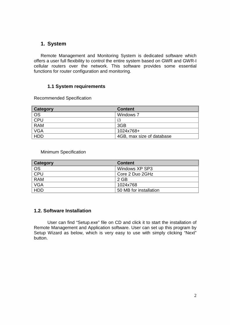
1.1 System requirements Recommended Specification Category Content OS Windows 7 CPU i3 RAM 3GB VGA 1024x768+ HDD 4GB, max size of database
Minimum Specification
Category Content OS Windows XP SP3 CPU Core 2 Duo 2GHz RAM 2 GB VGA 1024x768 HDD 50 MB for installation
1.2. Software Installation
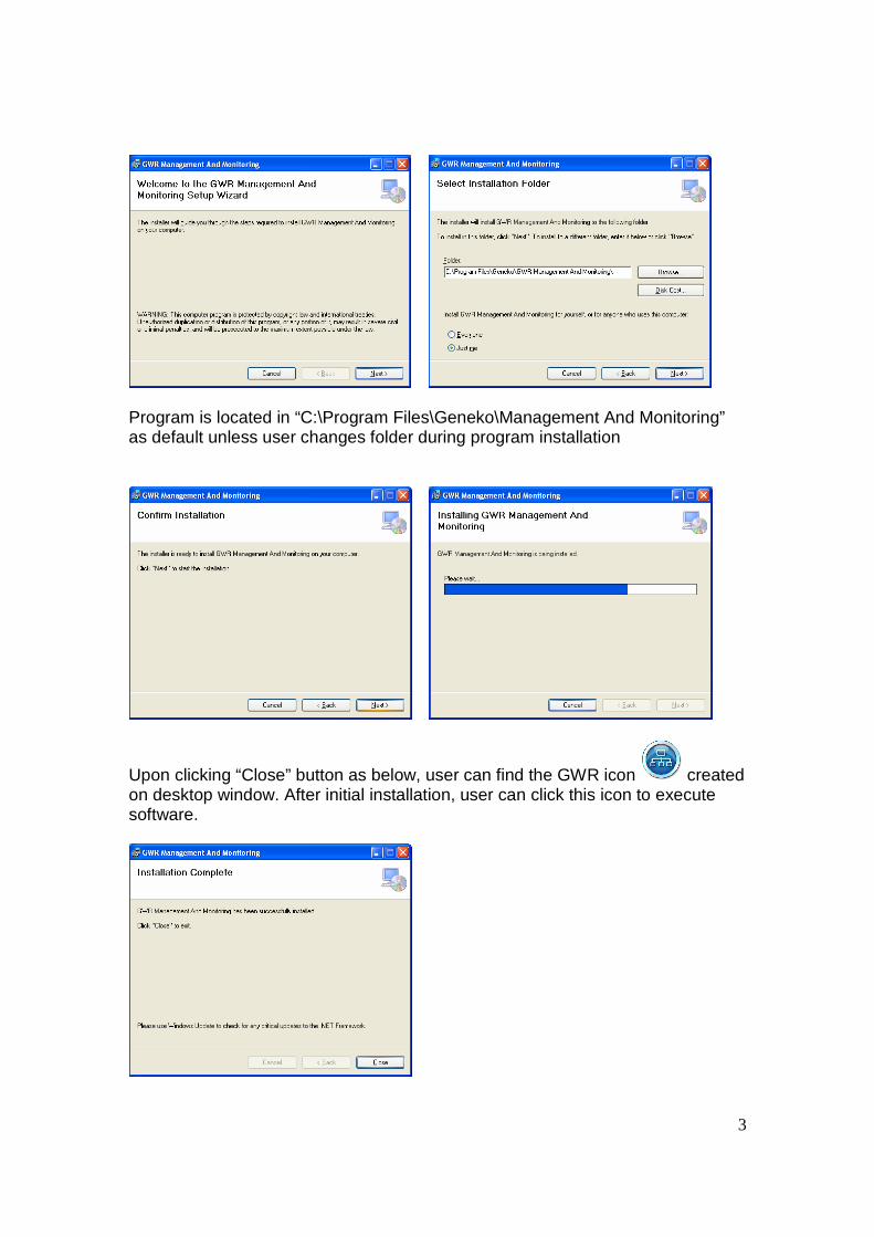
User can find “Setup.exe” file on CD and click it to start the installation of Remote Management and Application software. User can set up this program by Setup Wizard as below, which is very easy to use with simply clicking “Next” button.
3
Program is located in “C:\Program Files\Geneko\Management And Monitoring” as default unless user changes folder during program installation
Upon clicking “Close” button as below, user can find the GWR icon created on desktop window. After initial installation, user can click this icon to execute software.
4
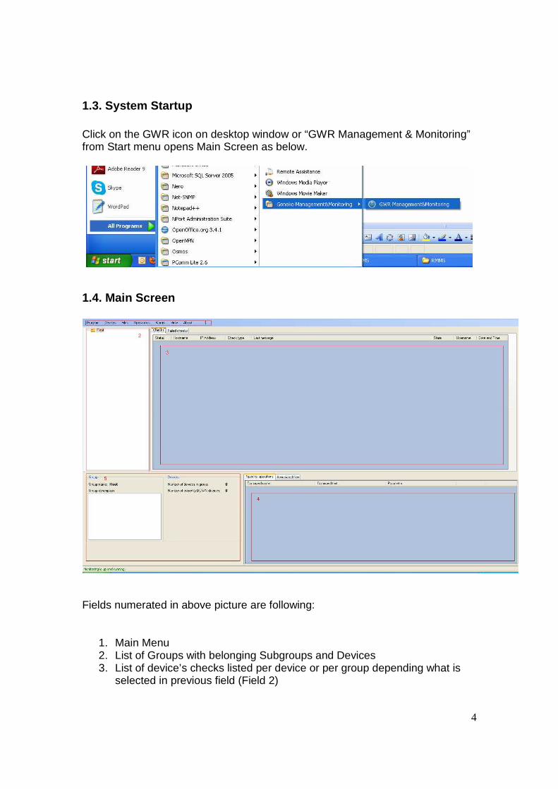
1.3. System Startup Click on the GWR icon on desktop window or “GWR Management & Monitoring” from Start menu opens Main Screen as below.
1.4. Main Screen
Fields numerated in above picture are following:
1. Main Menu 2. List of Groups with belonging Subgroups and Devices 3. List of device’s checks listed per device or per group depending what is
selected in previous field (Field 2)
5
4. List of associated Specific commands or Files for device selected in field number 2
5. Status of the Group or Device selected in field 2
2. System Settings
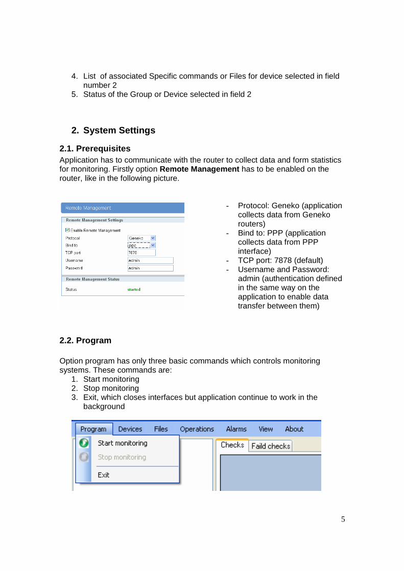
2.1. Prerequisites Application has to communicate with the router to collect data and form statistics for monitoring. Firstly option Remote Management has to be enabled on the router, like in the following picture.
- Protocol: Geneko (application collects data from Geneko routers)
- Bind to: PPP (application collects data from PPP interface)
- TCP port: 7878 (default) - Username and Password:
admin (authentication defined in the same way on the application to enable data transfer between them)
2.2. Program Option program has only three basic commands which controls monitoring systems. These commands are:
1. Start monitoring 2. Stop monitoring 3. Exit, which closes interfaces but application continue to work in the
background
6
2.3. Devices Option devices allows only basic add and device search. To command ADD be effective device group must be added first. When application is started for the first time group ROOT is already configured.
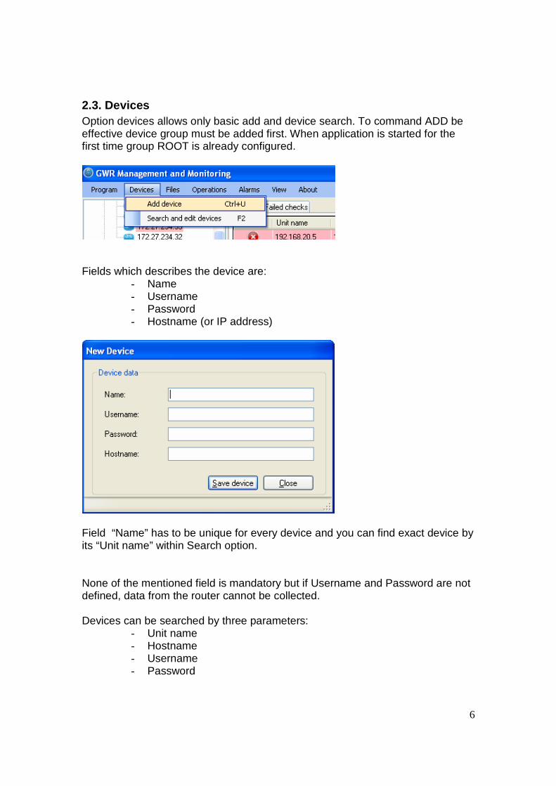
Fields which describes the device are:
- Name - Username - Password - Hostname (or IP address)
Field “Name” has to be unique for every device and you can find exact device by its “Unit name” within Search option. None of the mentioned field is mandatory but if Username and Password are not defined, data from the router cannot be collected. Devices can be searched by three parameters:
- Unit name - Hostname - Username - Password
7
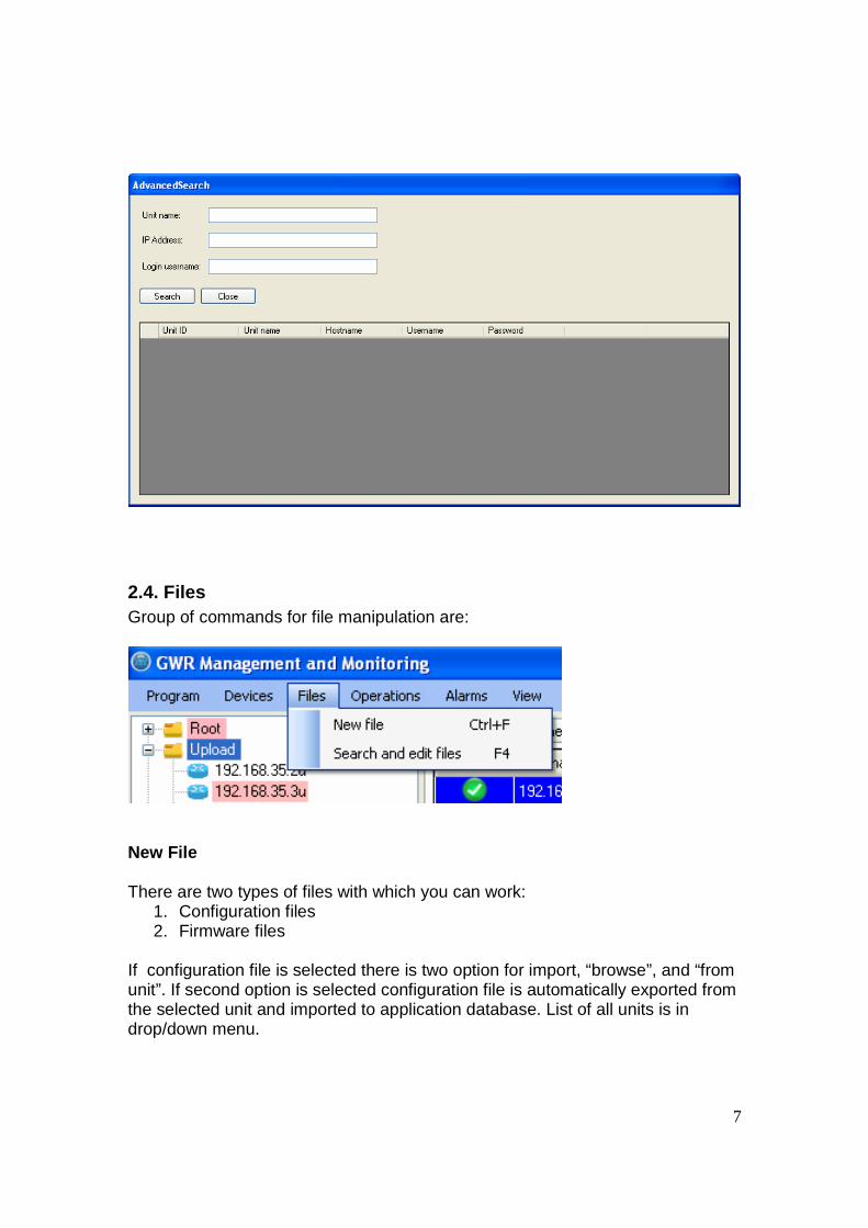
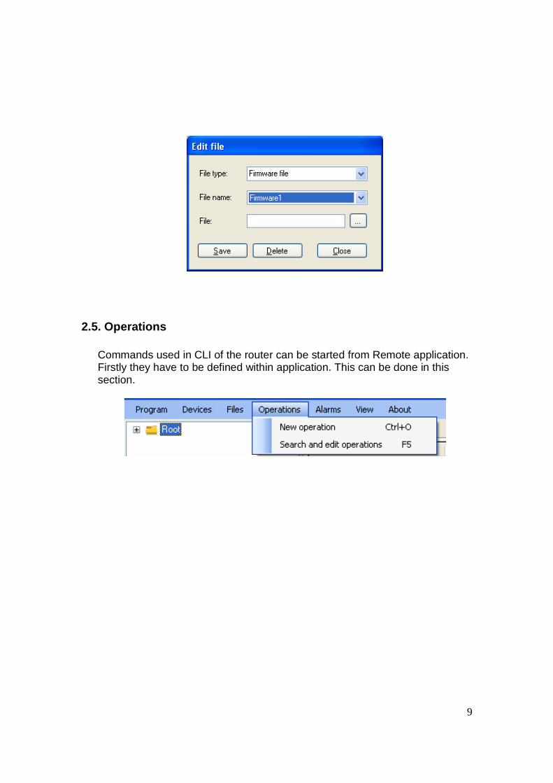
2.4. Files Group of commands for file manipulation are:
New File There are two types of files with which you can work:
1. Configuration files 2. Firmware files
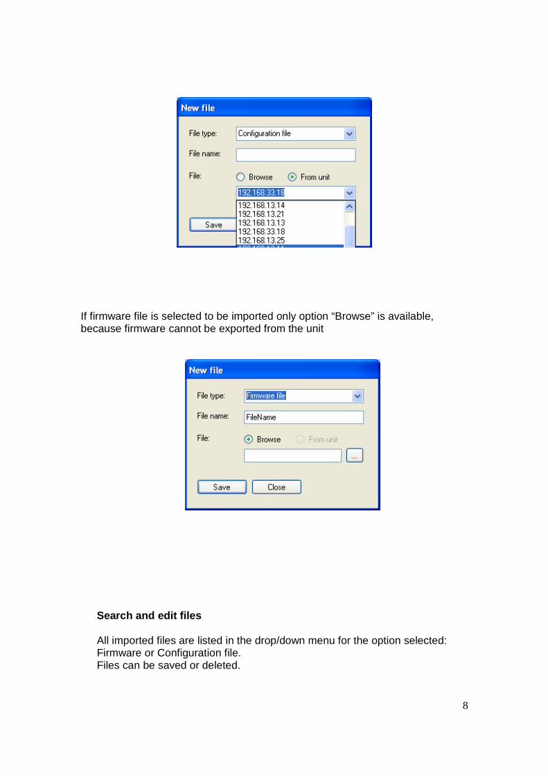
If configuration file is selected there is two option for import, “browse”, and “from unit”. If second option is selected configuration file is automatically exported from the selected unit and imported to application database. List of all units is in drop/down menu.
8
If firmware file is selected to be imported only option “Browse” is available, because firmware cannot be exported from the unit
Search and edit files All imported files are listed in the drop/down menu for the option selected: Firmware or Configuration file. Files can be saved or deleted.
9
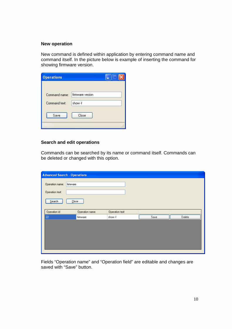
2.5. Operations
Commands used in CLI of the router can be started from Remote application. Firstly they have to be defined within application. This can be done in this section.
10
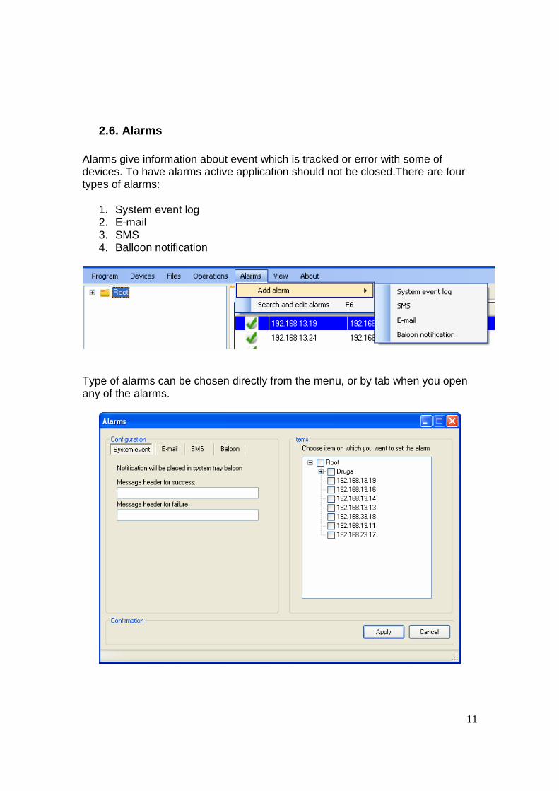
New operation New command is defined within application by entering command name and command itself. In the picture below is example of inserting the command for showing firmware version.
Search and edit operations Commands can be searched by its name or command itself. Commands can be deleted or changed with this option.
Fields “Operation name” and “Operation field” are editable and changes are saved with “Save” button.
11
2.6. Alarms Alarms give information about event which is tracked or error with some of devices. To have alarms active application should not be closed.There are four types of alarms:
1. System event log 2. E-mail 3. SMS 4. Balloon notification
Type of alarms can be chosen directly from the menu, or by tab when you open any of the alarms.
12
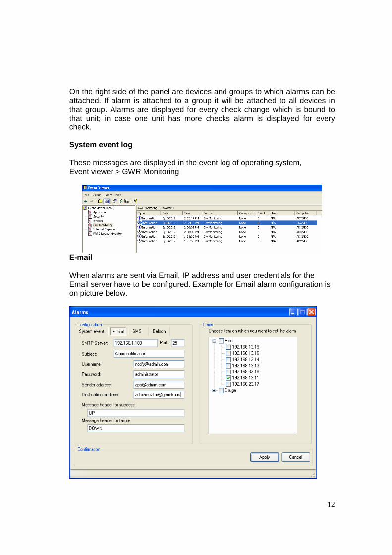
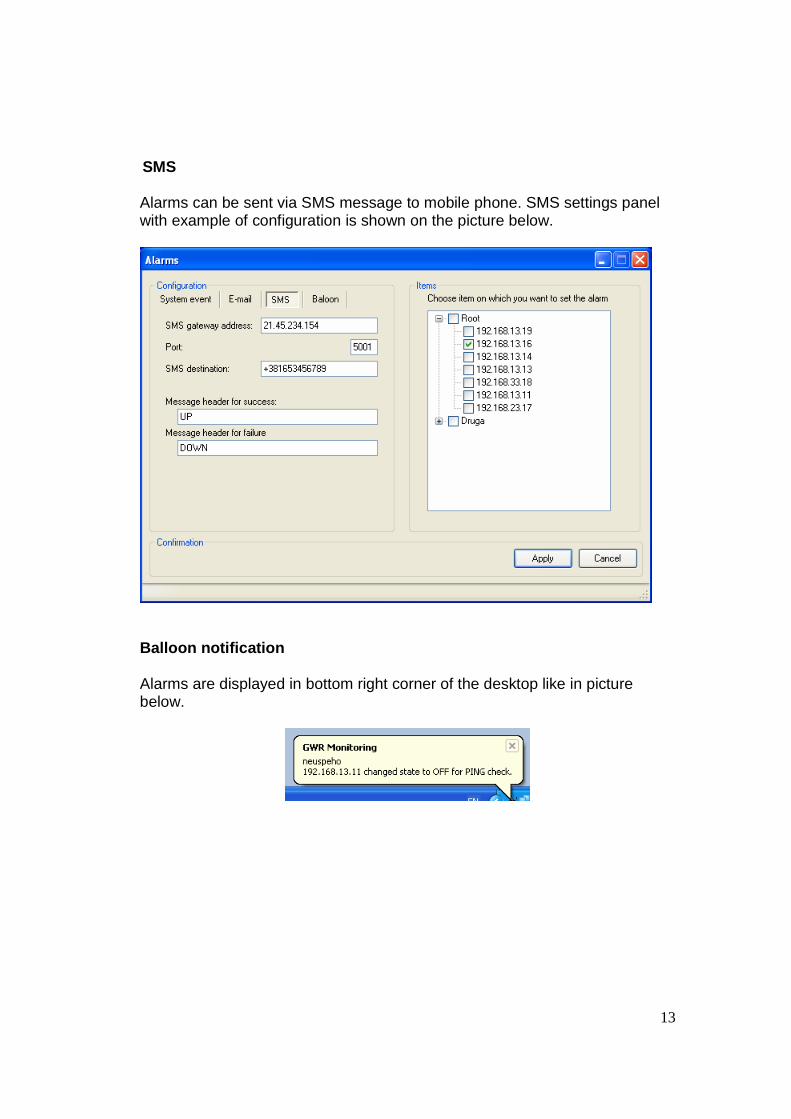
On the right side of the panel are devices and groups to which alarms can be attached. If alarm is attached to a group it will be attached to all devices in that group. Alarms are displayed for every check change which is bound to that unit; in case one unit has more checks alarm is displayed for every check. System event log These messages are displayed in the event log of operating system, Event viewer > GWR Monitoring
When alarms are sent via Email, IP address and user credentials for the Email server have to be configured. Example for Email alarm configuration is on picture below.
13
SMS
Alarms can be sent via SMS message to mobile phone. SMS settings panel with example of configuration is shown on the picture below.
Balloon notification Alarms are displayed in bottom right corner of the desktop like in picture below.
14
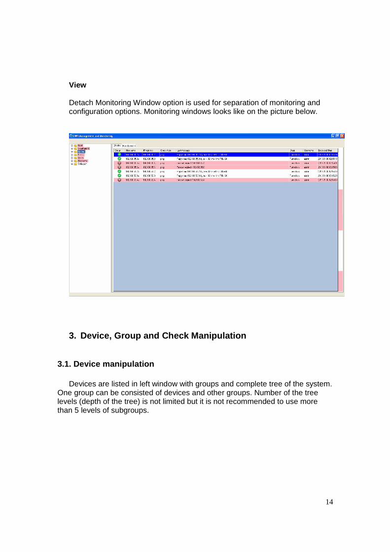
View Detach Monitoring Window option is used for separation of monitoring and configuration options. Monitoring windows looks like on the picture below.
3. Device, Group and Check Manipulation
3.1. Device manipulation
Devices are listed in left window with groups and complete tree of the system. One group can be consisted of devices and other groups. Number of the tree levels (depth of the tree) is not limited but it is not recommended to use more than 5 levels of subgroups.
15
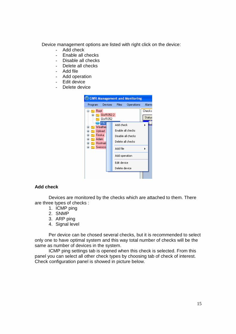
Device management options are listed with right click on the device: - Add check - Enable all checks - Disable all checks - Delete all checks - Add file - Add operation - Edit device - Delete device
Add check
Devices are monitored by the checks which are attached to them. There are three types of checks :
1. ICMP ping 2. SNMP 3. ARP ping 4. Signal level Per device can be chosed several checks, but it is recommended to select
only one to have optimal system and this way total number of checks will be the same as number of devices in the system.
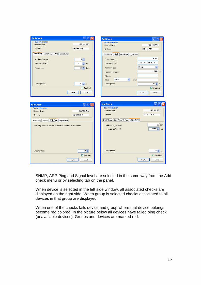
ICMP ping settings tab is opened when this check is selected. From this panel you can select all other check types by choosing tab of check of interest. Check configuration panel is showed in picture below.
16
SNMP, ARP Ping and Signal level are selected in the same way from the Add check menu or by selecting tab on the panel. When device is selected in the left side window, all associated checks are displayed on the right side. When group is selected checks associated to all devices in that group are displayed When one of the checks fails device and group where that device belongs become red colored. In the picture below all devices have failed ping check (unavailable devices). Groups and devices are marked red.
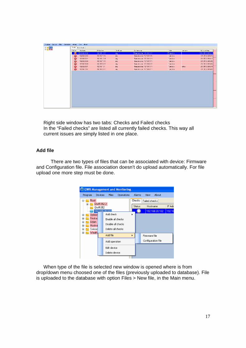
17
Right side window has two tabs: Checks and Failed checks In the “Failed checks” are listed all currently failed checks. This way all current issues are simply listed in one place.
Add file There are two types of files that can be associated with device: Firmware and Configuration file. File association doesn’t do upload automatically. For file upload one more step must be done.
When type of the file is selected new window is opened where is from drop/down menu choosed one of the files (previously uploaded to database). File is uploaded to the database with option Files > New file, in the Main menu.
18
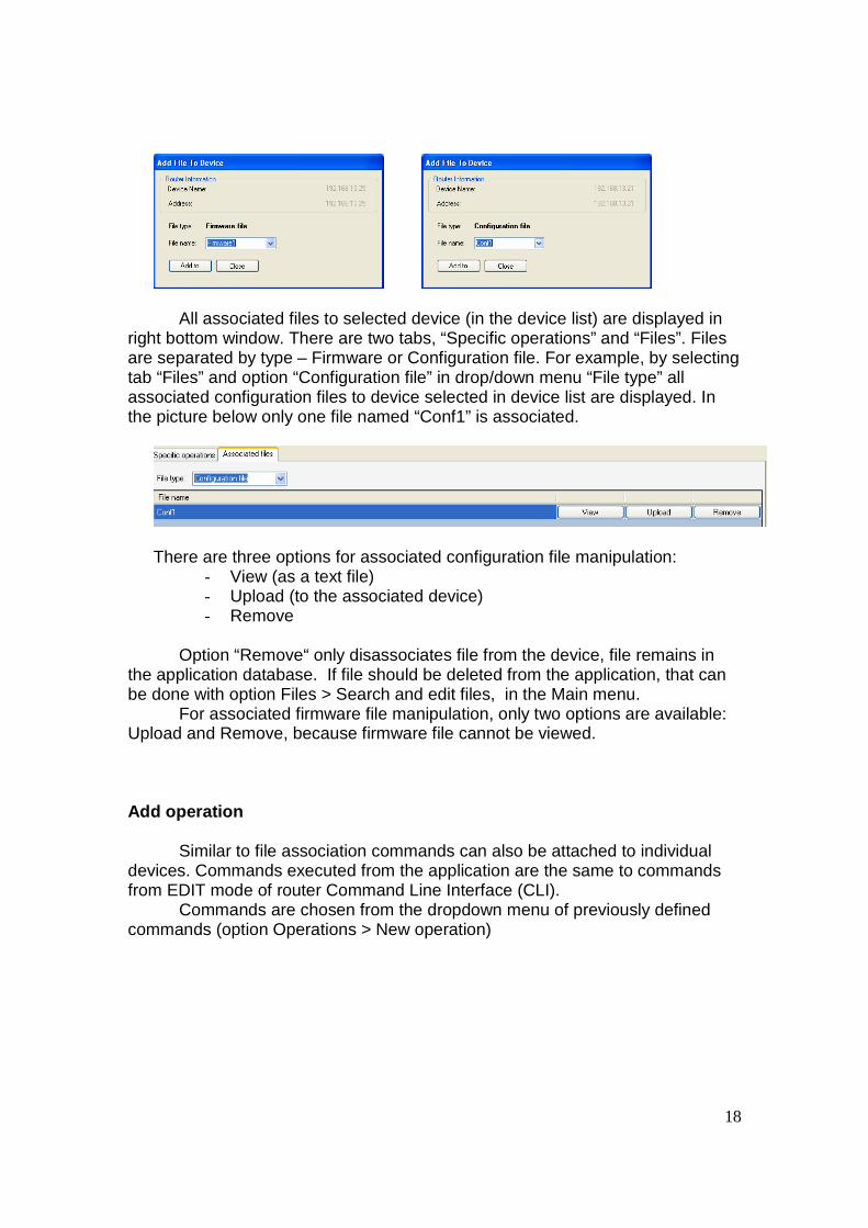
All associated files to selected device (in the device list) are displayed in right bottom window. There are two tabs, “Specific operations” and “Files”. Files are separated by type – Firmware or Configuration file. For example, by selecting tab “Files” and option “Configuration file” in drop/down menu “File type” all associated configuration files to device selected in device list are displayed. In the picture below only one file named “Conf1” is associated.
There are three options for associated configuration file manipulation:
- View (as a text file) - Upload (to the associated device) - Remove
Option “Remove“ only disassociates file from the device, file remains in the application database. If file should be deleted from the application, that can be done with option Files > Search and edit files, in the Main menu.
For associated firmware file manipulation, only two options are available: Upload and Remove, because firmware file cannot be viewed. Add operation Similar to file association commands can also be attached to individual devices. Commands executed from the application are the same to commands from EDIT mode of router Command Line Interface (CLI). Commands are chosen from the dropdown menu of previously defined commands (option Operations > New operation)
19
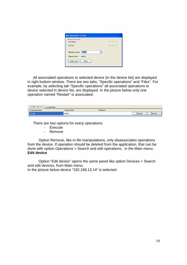
All associated operations to selected device (in the device list) are displayed
in right bottom window. There are two tabs, “Specific operations” and “Files”. For example, by selecting tab “Specific operations” all associated operations to device selected in device list, are displayed. In the picture below only one operation named “Restart” is associated.
There are two options for every operations:
- Execute - Remove
Option Remove, like in file manipulations, only disassociates operations
from the device. If operation should be deleted from the application, that can be done with option Operations > Search and edit operations, in the Main menu. Edit device Option “Edit device“ opens the same panel like option Devices > Search and edit devices, from Main menu. In the picture below device “192.168.13.14“ is selected.
20
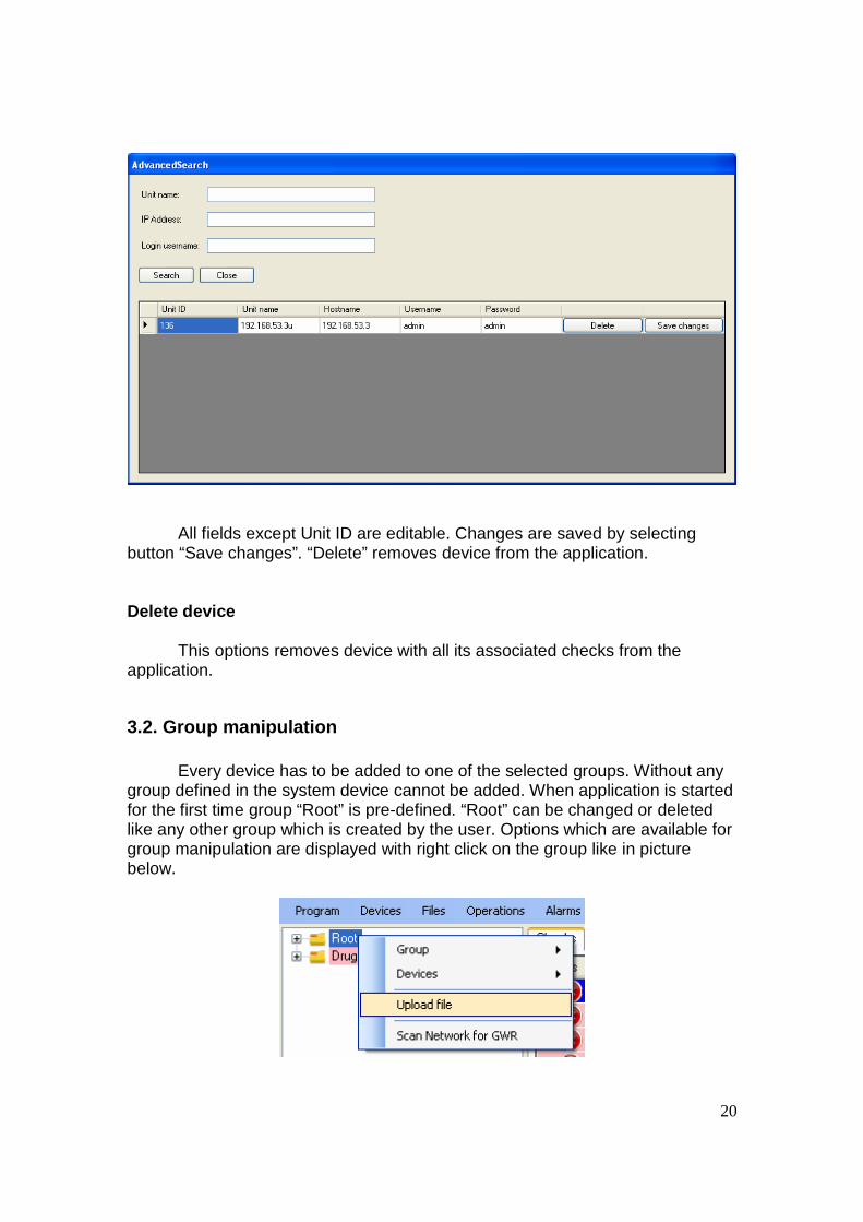
All fields except Unit ID are editable. Changes are saved by selecting
button “Save changes”. “Delete” removes device from the application. Delete device This options removes device with all its associated checks from the application.
3.2. Group manipulation Every device has to be added to one of the selected groups. Without any group defined in the system device cannot be added. When application is started for the first time group “Root” is pre-defined. “Root” can be changed or deleted like any other group which is created by the user. Options which are available for group manipulation are displayed with right click on the group like in picture below.
21
Application provides four options for group manipulation:
1. Group 2. Devices 3. Upload file 4. Scan Network for GWR Group Option “Group” provides basic group operation:
- Add group - Edit group - Delete group - Add check - Delete all checks - Enable all checks - Disable all checks - Add Operation - Export this node - Group Info
When new group is formed name and description of the group should be
entered. These fields are also shown when “Edit group” is selected. Name of the group is displayed in system tree as the group ID.
When group is deleted all attached devices are also deleted with all belonging checks to those devices.
Checks can be added to group level the same way like on device level (3.1. – Add check). When check is added on group level it is added to all devices related to that group. If any of device already has some check, it will get one more check inherited from the group. That also applies to checks of the same type, device can have two identical checks (highly not recommendable).
Checks can be enabled, disabled and deleted on group level. Commands can be added per group and all devices in the group and
subgroups will have commands assigned. Export from the application is possible only per group. Exported file is in
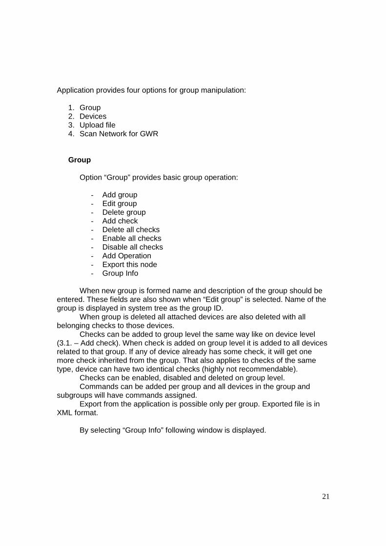
XML format. By selecting “Group Info” following window is displayed.
22
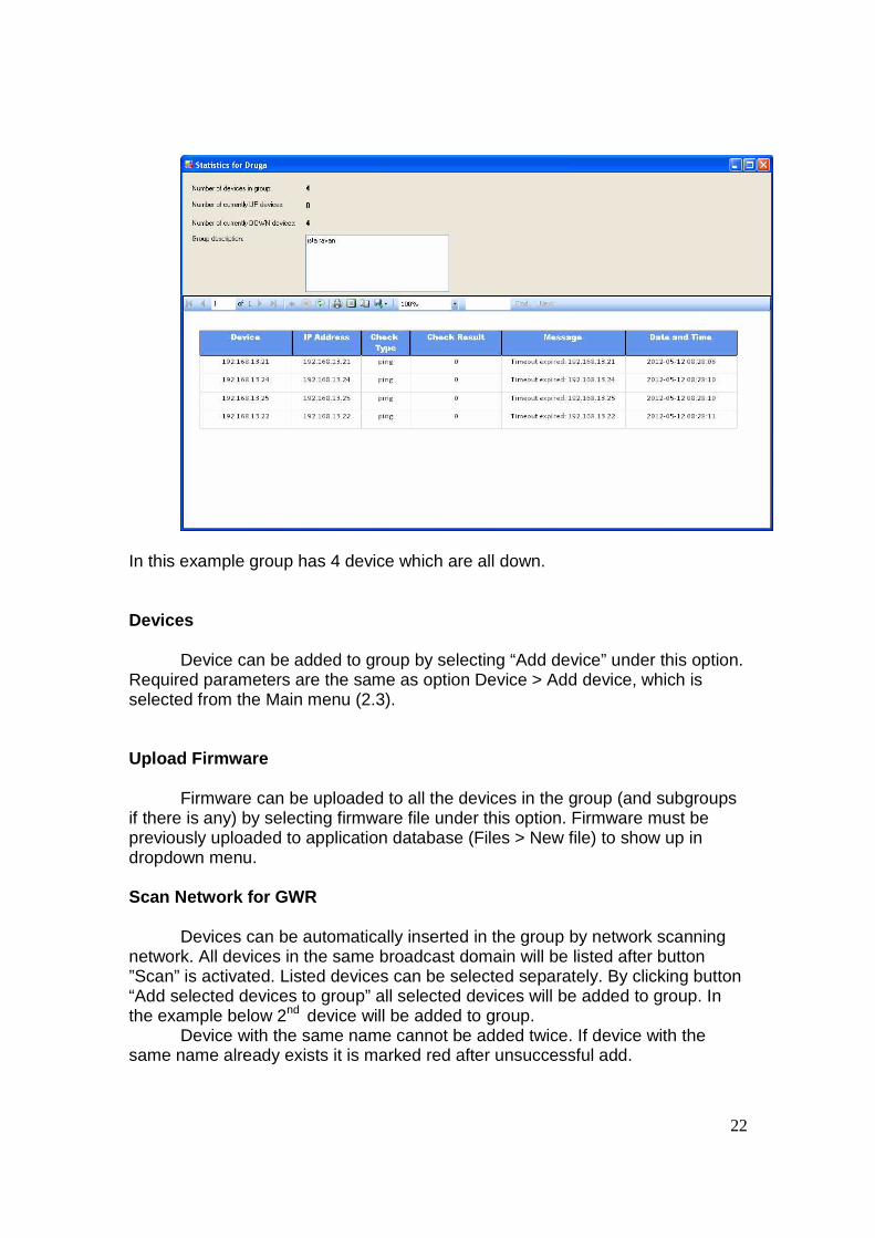
In this example group has 4 device which are all down. Devices Device can be added to group by selecting “Add device” under this option. Required parameters are the same as option Device > Add device, which is selected from the Main menu (2.3). Upload Firmware Firmware can be uploaded to all the devices in the group (and subgroups if there is any) by selecting firmware file under this option. Firmware must be previously uploaded to application database (Files > New file) to show up in dropdown menu. Scan Network for GWR Devices can be automatically inserted in the group by network scanning network. All devices in the same broadcast domain will be listed after button ”Scan” is activated. Listed devices can be selected separately. By clicking button “Add selected devices to group” all selected devices will be added to group. In the example below 2nd device will be added to group. Device with the same name cannot be added twice. If device with the same name already exists it is marked red after unsuccessful add.
23
If field “Pingable” is ticked, device can be reached over router IP address, if that is not the case router cannot be reached over displayed IP address.
3.3. Check manipulation
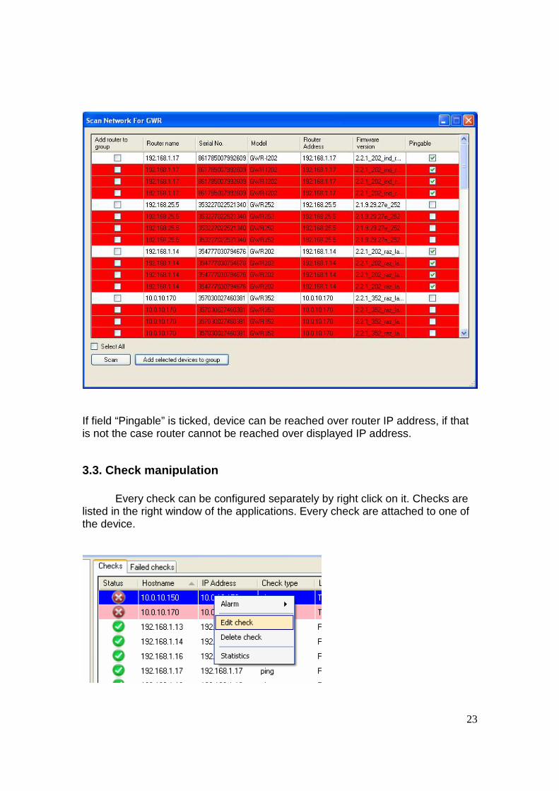
Every check can be configured separately by right click on it. Checks are listed in the right window of the applications. Every check are attached to one of the device.
24
Alarm
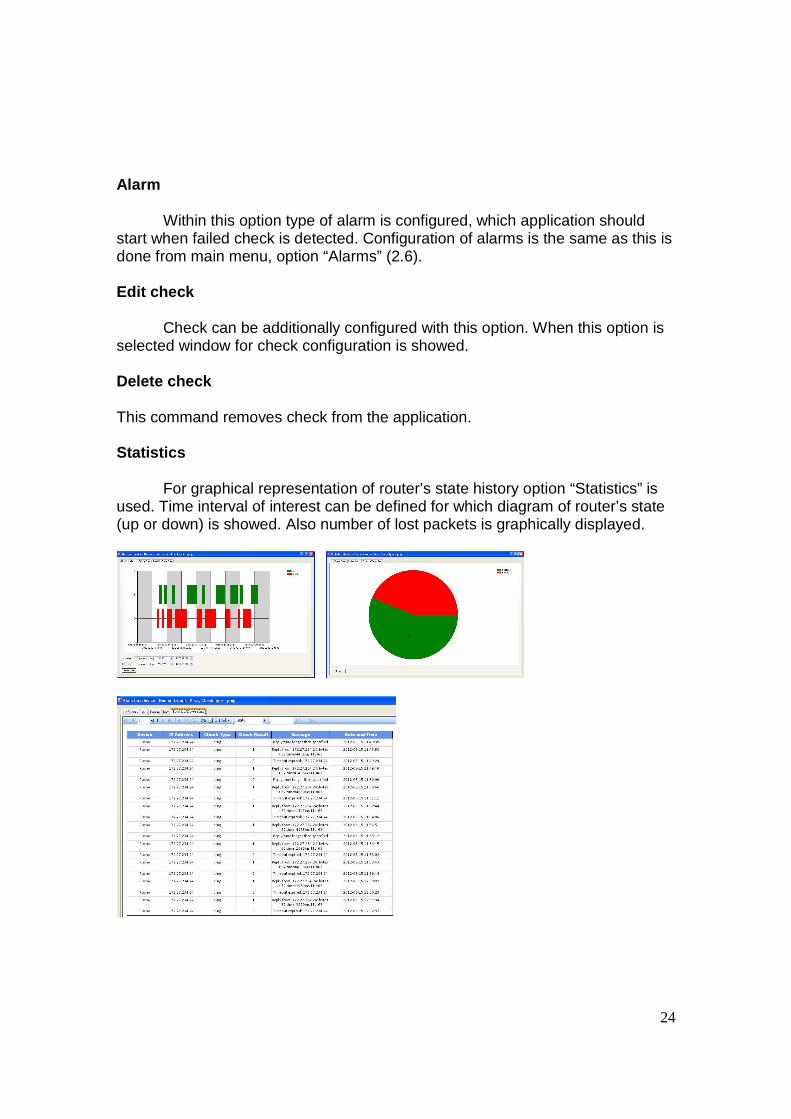
Within this option type of alarm is configured, which application should start when failed check is detected. Configuration of alarms is the same as this is done from main menu, option “Alarms” (2.6). Edit check Check can be additionally configured with this option. When this option is selected window for check configuration is showed. Delete check This command removes check from the application. Statistics
For graphical representation of router’s state history option “Statistics” is used. Time interval of interest can be defined for which diagram of router’s state (up or down) is showed. Also number of lost packets is graphically displayed.
25
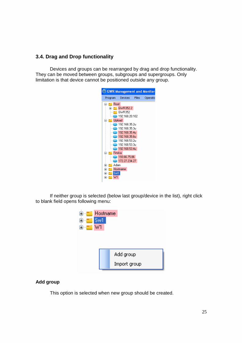
3.4. Drag and Drop functionality
Devices and groups can be rearranged by drag and drop functionality. They can be moved between groups, subgroups and supergroups. Only limitation is that device cannot be positioned outside any group.
If neither group is selected (below last group/device in the list), right click
to blank field opens following menu:
Add group This option is selected when new group should be created.

26
Import group With this option import of previously exported group is imported. File format supported is XML.