Embed Size (px)
Citation preview
Remote Leaf Switches
This chapter contains the following sections:
• About Remote Leaf Switches in the ACI Fabric, on page 1• Remote Leaf Switch Hardware Requirements, on page 2• Restrictions and Limitations, on page 3• WAN Router and Remote Leaf Switch Configuration Guidelines, on page 4• Configure Remote Leaf Switches Using the REST API, on page 5• Configure Remote Leaf Switches Using the NX-OS Style CLI, on page 8• Configure the Pod and Fabric Membership for Remote Leaf Switches Using the GUI, on page 11• Prerequisites Required Prior to Downgrading Remote Leaf Switches, on page 15
About Remote Leaf Switches in the ACI FabricWith an ACI fabric deployed, you can extend ACI services and APICmanagement to remote datacenters withCisco ACI leaf switches that have no local spine switch or APIC attached.
Remote Leaf Switches1
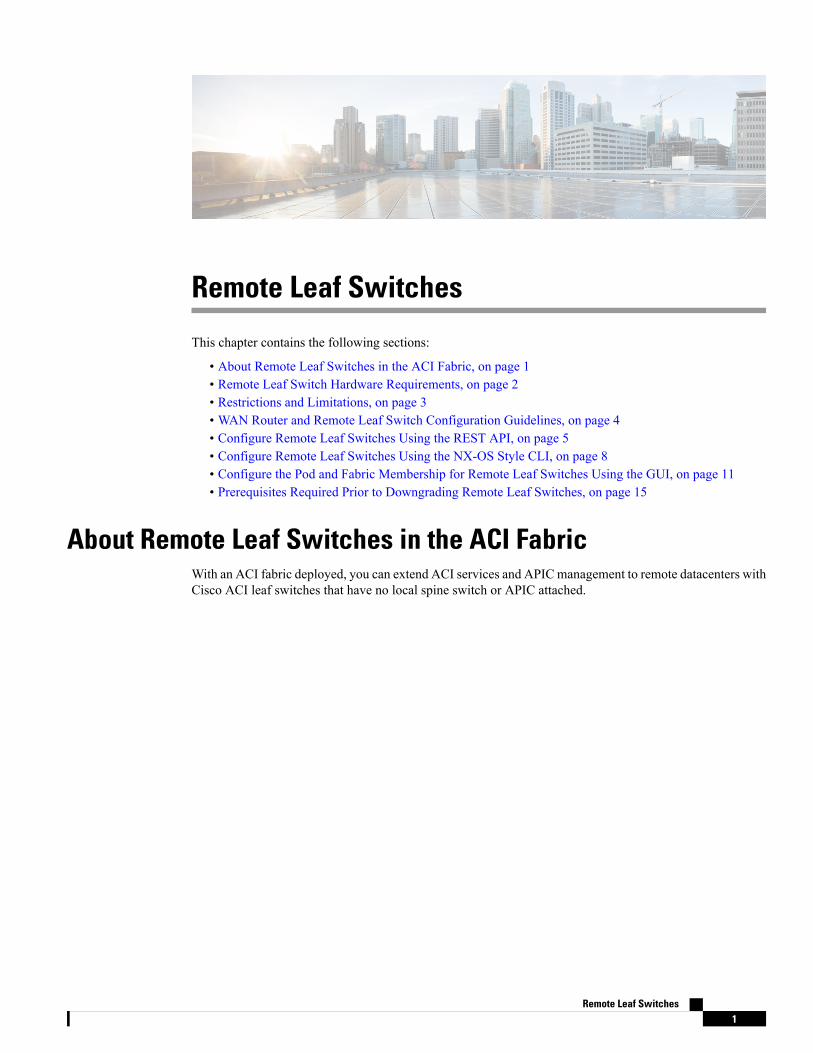
Figure 1: Remote Leaf Topology
The remote leaf switches are added to an existing pod in the fabric. All policies deployed in the main datacenterare deployed in the remote switches, which behave like local leaf switches belonging to the pod. In thistopology, all unicast traffic is through VXLAN over Layer 3. Layer 2 Broadcast, Unknown Unicast, andMulticast (BUM) messages are sent using Head End Replication (HER) tunnels without the use of Multicast.All local traffic on the remote site is switched directly between endpoints, whether physical or virtual. Anytraffic that requires use of the spine switch proxy is forwarded to the main datacenter.
The APIC system discovers the remote leaf switches when they come up. From that time, they can be managedthrough APIC, as part of the fabric.
• All inter-VRF traffic goes to the spine switch before being forwarded.
• Before decommissioning a remote leaf, you must first delete the vPC.
Note
You can configure Remote Leaf in the APIC GUI, either with and without a wizard, or use the REST API orthe NX-OS style CLI.
Remote Leaf Switch Hardware RequirementsThe following switches are supported for the Remote Leaf Switch feature.
Remote Leaf Switches2
Remote Leaf SwitchesRemote Leaf Switch Hardware Requirements
Fabric Spine Switches
For the spine switch at the ACI Main Datacenter that is connected to the WAN router, the following spineswitches are supported:
• Fixed spine switches Cisco Nexus 9000 series N9K-C9364C and N9K-C9332C
• For modular spine switches, only Cisco Nexus 9000 series switches with names that end in EX, and later(for example, N9K-X9732C- EX ) are supported.
• Older generation spine switches, such as the fixed spine switch N9K-C9336PQ or modular spine switcheswith the N9K-X9736PQ linecard are supported in the Main Datacenter, but only next generation spineswitches are supported to connect to the WAN.
Remote Leaf Switches
• For the remote leaf switches, only Cisco Nexus 9000 series switches with names that end in EX, andlater (for example, N9K-C93180LC-EX) are supported.
• The remote leaf switches must be running a switch image of 13.1.x or later (aci-n9000-dk9.13.1.x.x.bin)before they can be discovered. This may require manual upgrades on the leaf switches.
Restrictions and Limitations
In Cisco APIC Release 3.2(x), the following features are supported that were not previously:
• FEX devices connected to remote leaf switches
• Cisco AVS with VLAN and Cisco AVS with VXLAN
• Cisco ACI Virtual Edge with VLAN and ACI Virtual Edge with VXLAN
• The Cisco Nexus 9336C-FX2 switch is now supported for remote leaf switches
Note
Stretching of L3out SVI between local leaf switches (ACImain data center switches) and remote leaf switchesis not supported.
The following deployments and configurations are not supported with the remote leaf switch feature:
• APIC controllers directly connected to remote leaf switches
• Orphan port-channel or physical ports on remote leaf switches, with a vPC domain (this restriction appliesfor releases 3.1 and earlier)
• With and without service node integration, local traffic forwarding within a remote location is onlysupported if the consumer, provider, and services nodes are all connected to Remote Leaf switches arein vPC mode
Full fabric and tenant policies are supported on remote leaf switches, in this release, except for the followingfeatures:
• ACI Multi-Site
Remote Leaf Switches3
Remote Leaf SwitchesRestrictions and Limitations
• Layer 2 Outside Connections (except Static EPGs)
• 802.1Q Tunnels
• Copy services with vzAny contract
• FCoE connections on remote leaf switches
• Flood in encapsulation for bridge domains or EPGs
• Fast Link Failover policies
• Managed Service Graph-attached devices at remote locations
• Netflow
• PBR Tracking on remote leaf switches (with system-level global GIPo enabled)
• Q-in-Q Encapsulation Mapping for EPGs
• Traffic Storm Control
• Cloud Sec and MacSec Encryption
• First Hop Security
• PTP
• Layer 3 Multicast routing on remote leaf switches
• Openstack and Kubernetes VMM domains
• Maintenance mode
• Troubleshooting Wizard
• Transit L3Out across remote locations, which is when the main Cisco ACI datacenter pod is a transitbetween two remote locations (the L3Out in RL location-1 and L3Out in RL location-2 are advertisingprefixes for each other)
• Traffic forwarding directly across two remote leaf vPC pairs in the same remote datacenter or acrossdatacenters
WAN Router and Remote Leaf Switch Configuration GuidelinesBefore a remote leaf is discovered and incorporated in APIC management, you must configure the WANrouter and the remote leaf switches.
Configure the WAN routers that connect to the fabric spine switch external interfaces and the remote leafswitch ports, with the following requirements:
WAN Routers
• Enable OSPF on the interfaces, with the same details, such as area ID, type, and cost.
• Configure DHCP Relay on the interface leading to each APIC's IP address in the main fabric.
• The interfaces on the WAN routers which connect to the VLAN-5 interfaces on the spine switches mustbe on different VRFs than the interfaces connecting to a regular multipod network.
Remote Leaf Switches4
Remote Leaf SwitchesWAN Router and Remote Leaf Switch Configuration Guidelines
Remote Leaf Switches
• Connect the remote leaf switches to an upstream router by a direct connection from one of the fabricports. The following connections to the upstream router are supported:
• 40 Gbps & higher connections
• With a QSFP-to-SFP Adapter, supported 1G/10G SFPs
Bandwidth in the WAN varies, depending on the release:
• For releases prior to 4.2(4), bandwidth in theWANmust be a minimum of 100Mbps and maximumsupported latency is 300 msecs.
• For Release 4.2(4) and later, bandwidth in the WANmust be a minimum of 10 Mbps and maximumsupported latency is 300 msecs.
• It is recommended, but not required to connect the pair of remote leaf switches with a vPC. The switcheson both ends of the vPC must be remote leaf switches at the same remote datacenter.
• Configure the northbound interfaces as Layer 3 sub-interfaces on VLAN-4, with unique IP addresses.
If you connect more than one interface from the remote leaf switch to the router, configure each interfacewith a unique IP address.
• Enable OSPF on the interfaces, but do not set the OSPF area type as stub area.
• The IP addresses in the remote leaf switch TEP Pool subnet must not overlap with the pod TEP subnetpool. The subnet used must be /24 or lower.
• Multipod is supported, but not required, with the Remote Leaf feature.
• When connecting a pod in a single-pod fabric with remote leaf switches, configure an L3Out from aspine switch to the WAN router and an L3Out from a remote leaf switch to the WAN router, both usingVLAN-4 on the switch interfaces.
• When connecting a pod in a multipod fabric with remote leaf switches, configure an L3Out from a spineswitch to theWAN router and an L3Out from a remote leaf switch to theWAN router, both using VLAN-4on the switch interfaces. Also configure a multipod-internal L3Out using VLAN-5 to support traffic thatcrosses pods destined to a remote leaf switch. The regular multipod and multipod-internal connectionscan be configured on the same physical interfaces, as long as they use VLAN-4 and VLAN-5.
• When configuring theMultipod-internal L3Out, use the same router ID as for the regular multipod L3Out,but deselect the Use Router ID as Loopback Address option for the router-id and configure a differentloopback IP address. This enables ECMP to function.
Configure Remote Leaf Switches Using the REST APITo enable Cisco APIC to discover and connect the IPN router and remote leaf switches, perform the steps inthis topic.
This example assumes that the remote leaf switches are connected to a pod in a multipod topology. It includestwo L3Outs configured in the infra tenant, with VRF overlay-1:
• One is configured on VLAN-4, that is required for both the remote leaf switches and the spine switchconnected to the WAN router.
Remote Leaf Switches5
Remote Leaf SwitchesConfigure Remote Leaf Switches Using the REST API
• One is the multipod-internal L3Out configured on VLAN-5, that is required for the multipod and RemoteLeaf features, when they are deployed together.
Procedure
Step 1 To define the TEP pool for two remote leaf switches to be connected to a pod, send a post with XML such asthe following example:
Example:<fabricSetupPol>
<fabricSetupP tepPool="10.0.0.0/16" podId="1" ><fabricExtSetupP tepPool="30.0.128.0/20" extPoolId="1"/>
</fabricSetupP><fabricSetupP tepPool="10.1.0.0/16" podId="2" >
<fabricExtSetupP tepPool="30.1.128.0/20" extPoolId="1"/></fabricSetupP>
</fabricSetupPol>
Step 2 To define the node identity policy, send a post with XML, such as the following example:
Example:<fabricNodeIdentPol>
<fabricNodeIdentP serial="SAL17267Z7W" name="leaf1" nodeId="101" podId="1"extPoolId="1" nodeType="remote-leaf-wan"/>
<fabricNodeIdentP serial="SAL17267Z7X" name="leaf2" nodeId="102" podId="1"extPoolId="1" nodeType="remote-leaf-wan"/>
<fabricNodeIdentP serial="SAL17267Z7Y" name="leaf3" nodeId="201" podId="1"extPoolId="1" nodeType="remote-leaf-wan"/>
<fabricNodeIdentP serial="SAL17267Z7Z" name="leaf4" nodeId="201" podId="1"extPoolId="1" nodeType="remote-leaf-wan"/></fabricNodeIdentPol>
Step 3 To configure the Fabric External Connection Profile, send a post with XML such as the following example:
Example:<?xml version="1.0" encoding="UTF-8"?><imdata totalCount="1">
<fvFabricExtConnP dn="uni/tn-infra/fabricExtConnP-1" id="1" name="Fabric_Ext_Conn_Pol1"rt="extended:as2-nn4:5:16" siteId="0">
<l3extFabricExtRoutingP name="test"><l3extSubnet ip="150.1.0.0/16" scope="import-security"/>
</l3extFabricExtRoutingP><l3extFabricExtRoutingP name="ext_routing_prof_1">
<l3extSubnet ip="204.1.0.0/16" scope="import-security"/><l3extSubnet ip="209.2.0.0/16" scope="import-security"/><l3extSubnet ip="202.1.0.0/16" scope="import-security"/><l3extSubnet ip="207.1.0.0/16" scope="import-security"/><l3extSubnet ip="200.0.0.0/8" scope="import-security"/><l3extSubnet ip="201.2.0.0/16" scope="import-security"/><l3extSubnet ip="210.2.0.0/16" scope="import-security"/><l3extSubnet ip="209.1.0.0/16" scope="import-security"/><l3extSubnet ip="203.2.0.0/16" scope="import-security"/><l3extSubnet ip="208.1.0.0/16" scope="import-security"/><l3extSubnet ip="207.2.0.0/16" scope="import-security"/><l3extSubnet ip="100.0.0.0/8" scope="import-security"/><l3extSubnet ip="201.1.0.0/16" scope="import-security"/><l3extSubnet ip="210.1.0.0/16" scope="import-security"/><l3extSubnet ip="203.1.0.0/16" scope="import-security"/><l3extSubnet ip="208.2.0.0/16" scope="import-security"/>
Remote Leaf Switches6
Remote Leaf SwitchesConfigure Remote Leaf Switches Using the REST API
</l3extFabricExtRoutingP><fvPodConnP id="1">
<fvIp addr="100.11.1.1/32"/></fvPodConnP><fvPodConnP id="2">
<fvIp addr="200.11.1.1/32"/></fvPodConnP><fvPeeringP type="automatic_with_full_mesh"/>
</fvFabricExtConnP></imdata>
Step 4 To configure an L3Out on VLAN-4, that is required for both the remote leaf switches and the spine switchconnected to the WAN router, enter XML such as the following example:
Example:<?xml version="1.0" encoding="UTF-8"?><polUni><fvTenant name="infra"><l3extOut name="rleaf-wan-test"><ospfExtP areaId="0.0.0.5"/><bgpExtP/><l3extRsEctx tnFvCtxName="overlay-1"/><l3extRsL3DomAtt tDn="uni/l3dom-l3extDom1"/><l3extProvLbl descr="" name="prov_mp1" ownerKey="" ownerTag="" tag="yellow-green"/><l3extLNodeP name="rleaf-101"><l3extRsNodeL3OutAtt rtrId="202.202.202.202" tDn="topology/pod-1/node-101"></l3extRsNodeL3OutAtt><l3extLIfP name="portIf"><l3extRsPathL3OutAtt ifInstT="sub-interface"
tDn="topology/pod-1/paths-101/pathep-[eth1/49]" addr="202.1.1.2/30" mac="AA:11:22:33:44:66"encap='vlan-4'/>
<ospfIfP><ospfRsIfPol tnOspfIfPolName='ospfIfPol'/>
</ospfIfP></l3extLIfP>
</l3extLNodeP><l3extLNodeP name="rlSpine-201"><l3extRsNodeL3OutAtt rtrId="201.201.201.201" rtrIdLoopBack="no"
tDn="topology/pod-1/node-201"><!--<l3extLoopBackIfP addr="201::201/128" descr="" name=""/><l3extLoopBackIfP addr="201.201.201.201/32" descr="" name=""/>--><l3extLoopBackIfP addr="::" />
</l3extRsNodeL3OutAtt><l3extLIfP name="portIf"><l3extRsPathL3OutAtt ifInstT="sub-interface"
tDn="topology/pod-1/paths-201/pathep-[eth8/36]" addr="201.1.1.1/30" mac="00:11:22:33:77:55"encap='vlan-4'/>
<ospfIfP><ospfRsIfPol tnOspfIfPolName='ospfIfPol'/>
</ospfIfP></l3extLIfP>
</l3extLNodeP><l3extInstP descr="" matchT="AtleastOne" name="instp1" prio="unspecified"
targetDscp="unspecified"><fvRsCustQosPol tnQosCustomPolName=""/>
</l3extInstP></l3extOut><ospfIfPol name="ospfIfPol" nwT="bcast"/>
</fvTenant></polUni>
Remote Leaf Switches7
Remote Leaf SwitchesConfigure Remote Leaf Switches Using the REST API
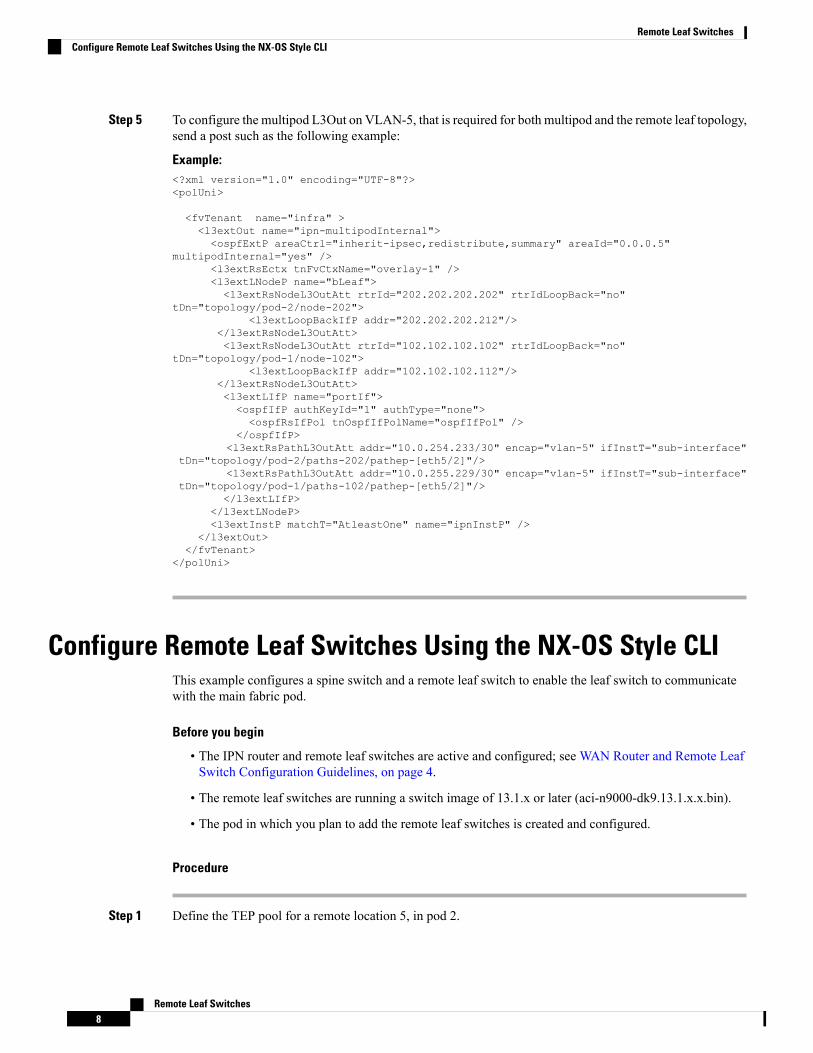
Step 5 To configure the multipod L3Out on VLAN-5, that is required for both multipod and the remote leaf topology,send a post such as the following example:
Example:<?xml version="1.0" encoding="UTF-8"?><polUni>
<fvTenant name="infra" ><l3extOut name="ipn-multipodInternal"><ospfExtP areaCtrl="inherit-ipsec,redistribute,summary" areaId="0.0.0.5"
multipodInternal="yes" /><l3extRsEctx tnFvCtxName="overlay-1" /><l3extLNodeP name="bLeaf"><l3extRsNodeL3OutAtt rtrId="202.202.202.202" rtrIdLoopBack="no"
tDn="topology/pod-2/node-202"><l3extLoopBackIfP addr="202.202.202.212"/>
</l3extRsNodeL3OutAtt><l3extRsNodeL3OutAtt rtrId="102.102.102.102" rtrIdLoopBack="no"
tDn="topology/pod-1/node-102"><l3extLoopBackIfP addr="102.102.102.112"/>
</l3extRsNodeL3OutAtt><l3extLIfP name="portIf"><ospfIfP authKeyId="1" authType="none"><ospfRsIfPol tnOspfIfPolName="ospfIfPol" />
</ospfIfP><l3extRsPathL3OutAtt addr="10.0.254.233/30" encap="vlan-5" ifInstT="sub-interface"
tDn="topology/pod-2/paths-202/pathep-[eth5/2]"/><l3extRsPathL3OutAtt addr="10.0.255.229/30" encap="vlan-5" ifInstT="sub-interface"
tDn="topology/pod-1/paths-102/pathep-[eth5/2]"/></l3extLIfP>
</l3extLNodeP><l3extInstP matchT="AtleastOne" name="ipnInstP" />
</l3extOut></fvTenant>
</polUni>
Configure Remote Leaf Switches Using the NX-OS Style CLIThis example configures a spine switch and a remote leaf switch to enable the leaf switch to communicatewith the main fabric pod.
Before you begin
• The IPN router and remote leaf switches are active and configured; see WAN Router and Remote LeafSwitch Configuration Guidelines, on page 4.
• The remote leaf switches are running a switch image of 13.1.x or later (aci-n9000-dk9.13.1.x.x.bin).
• The pod in which you plan to add the remote leaf switches is created and configured.
Procedure
Step 1 Define the TEP pool for a remote location 5, in pod 2.
Remote Leaf Switches8
Remote Leaf SwitchesConfigure Remote Leaf Switches Using the NX-OS Style CLI
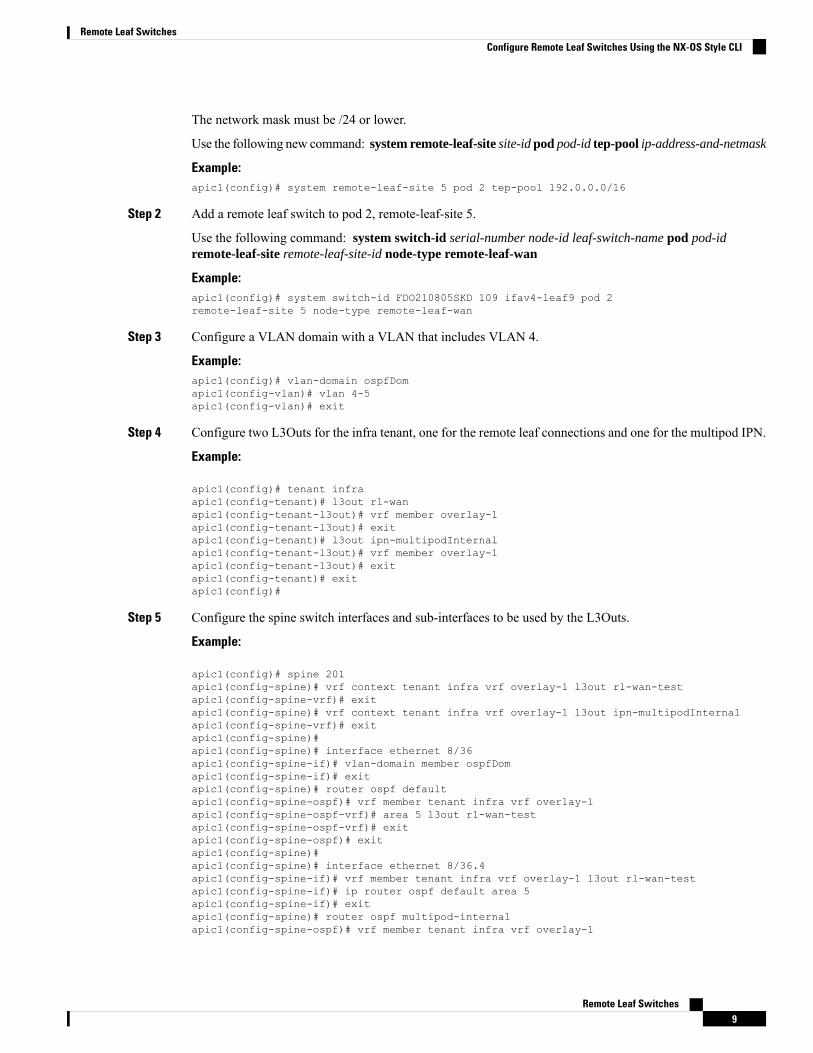
The network mask must be /24 or lower.
Use the following new command: system remote-leaf-site site-id pod pod-id tep-pool ip-address-and-netmask
Example:apic1(config)# system remote-leaf-site 5 pod 2 tep-pool 192.0.0.0/16
Step 2 Add a remote leaf switch to pod 2, remote-leaf-site 5.
Use the following command: system switch-id serial-number node-id leaf-switch-name pod pod-idremote-leaf-site remote-leaf-site-id node-type remote-leaf-wan
Example:apic1(config)# system switch-id FDO210805SKD 109 ifav4-leaf9 pod 2remote-leaf-site 5 node-type remote-leaf-wan
Step 3 Configure a VLAN domain with a VLAN that includes VLAN 4.
Example:apic1(config)# vlan-domain ospfDomapic1(config-vlan)# vlan 4-5apic1(config-vlan)# exit
Step 4 Configure two L3Outs for the infra tenant, one for the remote leaf connections and one for the multipod IPN.
Example:
apic1(config)# tenant infraapic1(config-tenant)# l3out rl-wanapic1(config-tenant-l3out)# vrf member overlay-1apic1(config-tenant-l3out)# exitapic1(config-tenant)# l3out ipn-multipodInternalapic1(config-tenant-l3out)# vrf member overlay-1apic1(config-tenant-l3out)# exitapic1(config-tenant)# exitapic1(config)#
Step 5 Configure the spine switch interfaces and sub-interfaces to be used by the L3Outs.
Example:
apic1(config)# spine 201apic1(config-spine)# vrf context tenant infra vrf overlay-1 l3out rl-wan-testapic1(config-spine-vrf)# exitapic1(config-spine)# vrf context tenant infra vrf overlay-1 l3out ipn-multipodInternalapic1(config-spine-vrf)# exitapic1(config-spine)#apic1(config-spine)# interface ethernet 8/36apic1(config-spine-if)# vlan-domain member ospfDomapic1(config-spine-if)# exitapic1(config-spine)# router ospf defaultapic1(config-spine-ospf)# vrf member tenant infra vrf overlay-1apic1(config-spine-ospf-vrf)# area 5 l3out rl-wan-testapic1(config-spine-ospf-vrf)# exitapic1(config-spine-ospf)# exitapic1(config-spine)#apic1(config-spine)# interface ethernet 8/36.4apic1(config-spine-if)# vrf member tenant infra vrf overlay-1 l3out rl-wan-testapic1(config-spine-if)# ip router ospf default area 5apic1(config-spine-if)# exitapic1(config-spine)# router ospf multipod-internalapic1(config-spine-ospf)# vrf member tenant infra vrf overlay-1
Remote Leaf Switches9
Remote Leaf SwitchesConfigure Remote Leaf Switches Using the NX-OS Style CLI
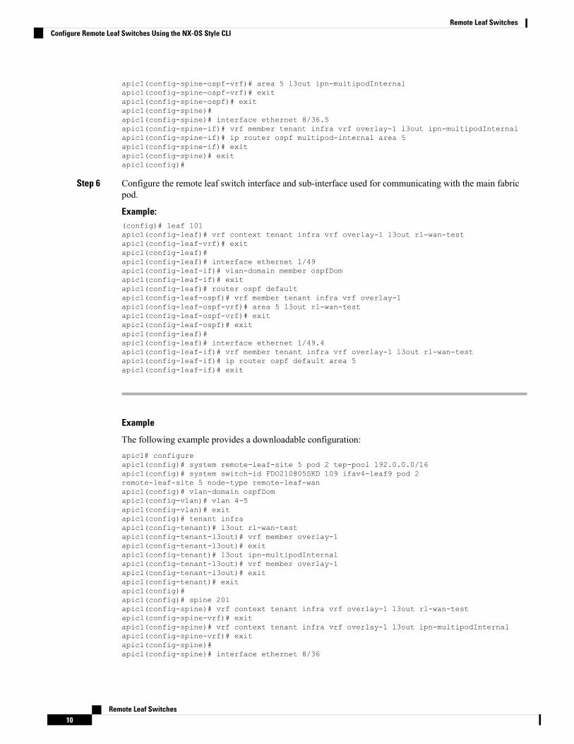
apic1(config-spine-ospf-vrf)# area 5 l3out ipn-multipodInternalapic1(config-spine-ospf-vrf)# exitapic1(config-spine-ospf)# exitapic1(config-spine)#apic1(config-spine)# interface ethernet 8/36.5apic1(config-spine-if)# vrf member tenant infra vrf overlay-1 l3out ipn-multipodInternalapic1(config-spine-if)# ip router ospf multipod-internal area 5apic1(config-spine-if)# exitapic1(config-spine)# exitapic1(config)#
Step 6 Configure the remote leaf switch interface and sub-interface used for communicating with the main fabricpod.
Example:(config)# leaf 101apic1(config-leaf)# vrf context tenant infra vrf overlay-1 l3out rl-wan-testapic1(config-leaf-vrf)# exitapic1(config-leaf)#apic1(config-leaf)# interface ethernet 1/49apic1(config-leaf-if)# vlan-domain member ospfDomapic1(config-leaf-if)# exitapic1(config-leaf)# router ospf defaultapic1(config-leaf-ospf)# vrf member tenant infra vrf overlay-1apic1(config-leaf-ospf-vrf)# area 5 l3out rl-wan-testapic1(config-leaf-ospf-vrf)# exitapic1(config-leaf-ospf)# exitapic1(config-leaf)#apic1(config-leaf)# interface ethernet 1/49.4apic1(config-leaf-if)# vrf member tenant infra vrf overlay-1 l3out rl-wan-testapic1(config-leaf-if)# ip router ospf default area 5apic1(config-leaf-if)# exit
Example
The following example provides a downloadable configuration:apic1# configureapic1(config)# system remote-leaf-site 5 pod 2 tep-pool 192.0.0.0/16apic1(config)# system switch-id FDO210805SKD 109 ifav4-leaf9 pod 2remote-leaf-site 5 node-type remote-leaf-wanapic1(config)# vlan-domain ospfDomapic1(config-vlan)# vlan 4-5apic1(config-vlan)# exitapic1(config)# tenant infraapic1(config-tenant)# l3out rl-wan-testapic1(config-tenant-l3out)# vrf member overlay-1apic1(config-tenant-l3out)# exitapic1(config-tenant)# l3out ipn-multipodInternalapic1(config-tenant-l3out)# vrf member overlay-1apic1(config-tenant-l3out)# exitapic1(config-tenant)# exitapic1(config)#apic1(config)# spine 201apic1(config-spine)# vrf context tenant infra vrf overlay-1 l3out rl-wan-testapic1(config-spine-vrf)# exitapic1(config-spine)# vrf context tenant infra vrf overlay-1 l3out ipn-multipodInternalapic1(config-spine-vrf)# exitapic1(config-spine)#apic1(config-spine)# interface ethernet 8/36
Remote Leaf Switches10
Remote Leaf SwitchesConfigure Remote Leaf Switches Using the NX-OS Style CLI
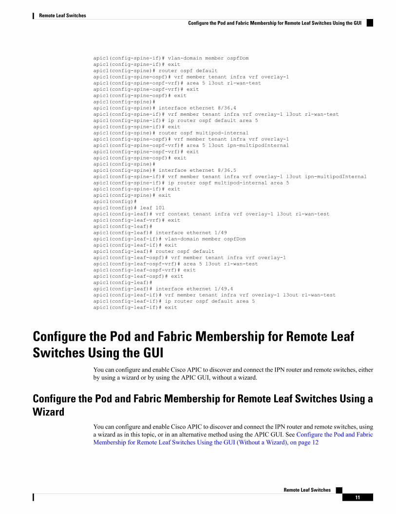
apic1(config-spine-if)# vlan-domain member ospfDomapic1(config-spine-if)# exitapic1(config-spine)# router ospf defaultapic1(config-spine-ospf)# vrf member tenant infra vrf overlay-1apic1(config-spine-ospf-vrf)# area 5 l3out rl-wan-testapic1(config-spine-ospf-vrf)# exitapic1(config-spine-ospf)# exitapic1(config-spine)#apic1(config-spine)# interface ethernet 8/36.4apic1(config-spine-if)# vrf member tenant infra vrf overlay-1 l3out rl-wan-testapic1(config-spine-if)# ip router ospf default area 5apic1(config-spine-if)# exitapic1(config-spine)# router ospf multipod-internalapic1(config-spine-ospf)# vrf member tenant infra vrf overlay-1apic1(config-spine-ospf-vrf)# area 5 l3out ipn-multipodInternalapic1(config-spine-ospf-vrf)# exitapic1(config-spine-ospf)# exitapic1(config-spine)#apic1(config-spine)# interface ethernet 8/36.5apic1(config-spine-if)# vrf member tenant infra vrf overlay-1 l3out ipn-multipodInternalapic1(config-spine-if)# ip router ospf multipod-internal area 5apic1(config-spine-if)# exitapic1(config-spine)# exitapic1(config)#apic1(config)# leaf 101apic1(config-leaf)# vrf context tenant infra vrf overlay-1 l3out rl-wan-testapic1(config-leaf-vrf)# exitapic1(config-leaf)#apic1(config-leaf)# interface ethernet 1/49apic1(config-leaf-if)# vlan-domain member ospfDomapic1(config-leaf-if)# exitapic1(config-leaf)# router ospf defaultapic1(config-leaf-ospf)# vrf member tenant infra vrf overlay-1apic1(config-leaf-ospf-vrf)# area 5 l3out rl-wan-testapic1(config-leaf-ospf-vrf)# exitapic1(config-leaf-ospf)# exitapic1(config-leaf)#apic1(config-leaf)# interface ethernet 1/49.4apic1(config-leaf-if)# vrf member tenant infra vrf overlay-1 l3out rl-wan-testapic1(config-leaf-if)# ip router ospf default area 5apic1(config-leaf-if)# exit
Configure the Pod and Fabric Membership for Remote LeafSwitches Using the GUI
You can configure and enable Cisco APIC to discover and connect the IPN router and remote switches, eitherby using a wizard or by using the APIC GUI, without a wizard.
Configure the Pod and Fabric Membership for Remote Leaf Switches Using aWizard
You can configure and enable Cisco APIC to discover and connect the IPN router and remote switches, usinga wizard as in this topic, or in an alternative method using the APIC GUI. See Configure the Pod and FabricMembership for Remote Leaf Switches Using the GUI (Without a Wizard), on page 12
Remote Leaf Switches11
Remote Leaf SwitchesConfigure the Pod and Fabric Membership for Remote Leaf Switches Using the GUI
Before you begin
• The IPN and WAN routers and remote leaf switches are active and configured; see WAN Router andRemote Leaf Switch Configuration Guidelines, on page 4.
• The remote leaf switch pair are connected with a vPC.
• The remote leaf switches are running a switch image of 13.1.x or later (aci-n9000-dk9.13.1.x.x.bin).
• The pod in which you plan to add the remote leaf switches is created and configured.
• The spine switch that will be used to connect the pod with the remote leaf swiches is connected to theIPN router.
Procedure
Step 1 On the menu bar click Fabric > Inventory.Step 2 In the Navigation pane, expand Quick Start and click Node or Pod Setup.Step 3 In the Remote Leaf pane of the working pane, click Setup Remote Leaf or right-click Node or Pod Setup
and click Setup Remote Leaf.Step 4 Follow the instructions to configure the following:
• Pod Fabric—Identify the pod and the TEP Pool subnet for the remote leaf switches.
Add the comma-separated subnets for the underlay routes leading to the remote leaf switches.
Repeat this for the other remote leaf switches to be added to the pod.
• Fabric Membership—Set up fabric membership for the remote leaf switches, including the node ID,Remote Leaf TEP Pool ID, and Remote Leaf Switch name.
• Remote Leaf—Configure Layer 3 details for the remote leaf switches, including the OSPF details (thesame OSPF configuration as in the WAN router), the router IDs and loopback addresses, and routedsub-interfaces for nodes.
• Connections—Configure the Layer 3 details for the spine switch for the L3Out on the route to the remoteleaf switches (only required if you are adding remote leaf switches to a single-pod fabric), including theOSPF details (same as configured in the IPN andWAN routers), the OSPF Profile, router IDs and routedsub-interfaces for the spine switches.
Configure the Pod and Fabric Membership for Remote Leaf Switches Usingthe GUI (Without a Wizard)
You can configure remote leaf switches using this GUI procedure, or use a wizard. For the wizard procedure,see Configure the Pod and Fabric Membership for Remote Leaf Switches Using a Wizard, on page 11
Before you begin
• The routers (IPN and WAN) and remote leaf switches are active and configured; see WAN Router andRemote Leaf Switch Configuration Guidelines, on page 4.
Remote Leaf Switches12
Remote Leaf SwitchesConfigure the Pod and Fabric Membership for Remote Leaf Switches Using the GUI (Without a Wizard)
• The remote leaf switches are running a switch image of 13.1.x or later (aci-n9000-dk9.13.1.x.x.bin).
• The pod in which you plan to add the remote leaf switches is created and configured.
• The spine switch that will be used to connect the pod with the remote leaf swiches is connected to theIPN router.
Procedure
Step 1 Configure the TEP pool for the remote leaf switches, with the following steps:a) On the menu bar, click Fabric > Inventory.b) In the Navigation pane, click Pod Fabric Setup Policy.c) On the Fabric Setup Policy panel, double-click the pod where you want to add the pair of remote leaf
switches.d) Click the + on the Remote Pools table.e) Enter the remote ID and a subnet for the remote TEP pool and click Submit.f) On the Fabric Setup Policy panel, click Submit.
Step 2 Configure the L3Out for the spine switch connected to the IPN router, with the following steps:a) On the menu bar, click Tenants > infra.b) In the Navigation pane, expandNetworking, right-clickExternal Routed Networks, and chooseCreate
Routed Outside.c) Enter a name for the L3Out.d) Click the OSPF checkbox to enable OSPF, and configure the OSPF details the same as on the IPN and
WAN routers.e) Only check theEnable Remote Leaf check box, if the pod where you are adding the remote leaf switches
is part of a multipod fabric.
This option enables a second OSPF instance using VLAN-5 for multipod, which ensures that routes forremote leaf switches are only advertised within the pod they belong to.
f) Choose the overlay-1 VRF.
Step 3 Configure the details for the spine and the interfaces used in the L3Out, with the following steps:a) Click the + on the Nodes and Interfaces Protocol Profiles table.b) Enter the node profile name.c) Click the + on the Nodes table, enter the following details.
• Node ID—ID for the spine switch that is connected to the IPN router.
• Router ID—IP address for the IPN router
• External Control Peering—disable if the pod where you are adding the remote leaf switches is in asingle-pod fabric
d) Click OK.e) Click the + on the OSPF Interface Profiles table.f) Enter the name of the interface profile and click Next.g) Under OSPF Profile, click OSPF Policy and choose a previously created policy or click Create OSPF
Interface Policy.h) Click Next.
Remote Leaf Switches13
Remote Leaf SwitchesConfigure the Pod and Fabric Membership for Remote Leaf Switches Using the GUI (Without a Wizard)
i) Click Routed Sub-Interface, click the + on the Routed Sub-Interfaces table, and enter the followingdetails:
• Node—Spine switch where the interface is located.
• Path—Interface connected to the IPN router
• Encap—Enter 4 for the VLAN
j) Click OK and click Next.k) Click the + on the External EPG Networks table.l) Enter the name of the external network, and click OK.m) Click Finish.
Step 4 To complete the fabric membership configuration for the remote leaf switches, perform the following steps:a) Navigate to Fabric > Inventory > Fabric Membership.
At this point, the new remote leaf switches should appear in the list of switches registered in the fabric.However, they are not recognized as remote leaf switches until you configure the Node Identity Policy,with the following steps.
b) For each remote leaf switch, double-click on the node in the list, configure the following details, and clickUpdate:
• Node ID—Remote leaf switch ID
• RL TEP Pool—Identifier for the remote leaf TEP pool, that you previously configured
• Node Name—Name of the remote leaf switch
After you configure the Node Identity Policy for each remote leaf switch, it is listed in the FabricMembership table with the role remote leaf.
Step 5 Configure the L3Out for the remote leaf location, with the following steps:a) Navigate to Tenants > infra > Networking.b) Right-click External Routed Networks, and choose Create Routed Outside.c) Enter a name for the L3Out.d) Click the OSPF checkbox to enable OSPF, and configure the OSPF details the same as on the IPN and
WAN router.e) Only check theEnable Remote Leaf check box, if the pod where you are adding the remote leaf switches
is part of a multipod fabric.f) Choose the overlay-1 VRF.
Step 6 Configure the nodes and interfaces leading from the remote leaf switches to theWAN router, with the followingsteps:a) In the Create Routed Outside panel, click the + on the Nodes and Interfaces Protocol Profiles table.b) Click the + on the Nodes table and enter the following details:
• Node ID—ID for the remote leaf that is connected to the WAN router
• Router ID—IP address for the WAN router
• External Control Peering—only enable if the remote leaf switches are being added to a pod in amultipod fabric
Remote Leaf Switches14
Remote Leaf SwitchesConfigure the Pod and Fabric Membership for Remote Leaf Switches Using the GUI (Without a Wizard)
c) Click OK.d) Click on the + onOSPF Interface Profiles, and configure the following details for the routed sub-interface
used to connect a remote leaf switch with the WAN router.
• Identity—Name of the OSPF interface profile
• Protocol Profiles—A previously configured OSPF profile or create one
• Interfaces—On the Routed Sub-Interface tab, the path and IP address for the routed sub-interfaceleading to the WAN router
Step 7 Configure the Fabric External Connection Profile, with the following steps:a) Navigate to Tenants > infra > Policies > Protocol.b) Right-click Fabric Ext Connection Policies and choose Create Intrasite/Intersite Profile.c) Enter the mandatory Community value in the format provided in the example.d) Click the + on Fabric External Routing Profile.e) Enter the name of the profile and add uplink interface subnets for all of the remote leaf switches.f) Click Update and click Submit.
Step 8 To verify that the remote leaf switches are discovered by the APIC, navigate to Fabric > Inventory > FabricMembership, or Fabric > Inventory > Pod > Topology.
Step 9 To view the status of the links between the fabric and the remote leaf switches, enter the show ip ospf neighborsvrf overlay-1 command on the spine switch that is connected to the IPN router.
Step 10 To view the status of the remote leaf switches in the fabric, enter the acidiag fnvread NX-OS style commandon the APIC using the CLI.
Prerequisites Required Prior to Downgrading Remote LeafSwitches
If you have remote leaf switches deployed, if you downgrade the APIC software from Release 3.1(1) or later,to an earlier release that does not support the Remote Leaf feature, you must decommission the remote nodesand remove the remote leaf-related policies (including the TEP Pool), before downgrading. Formore informationon decommissioning switches, see Decommissioning and Recommissioning Switches in the Cisco APICTroubleshooting Guide.
Note
Before you downgrade remote leaf switches, verify that the followings tasks are complete:
• Delete the vPC domain.
• Delete the vTEP - Virtual Network Adapter if using SCVMM.
• Decommission the remote leaf nodes, and wait 10 -15 minutes after the decommission for the task tocomplete.
• Delete the remote leaf to WAN L3out in the infra tenant.
• Delete the infra-l3out with VLAN 5 if using Multipod.
Remote Leaf Switches15
Remote Leaf SwitchesPrerequisites Required Prior to Downgrading Remote Leaf Switches

• Delete the remote TEP pools.
Remote Leaf Switches16
Remote Leaf SwitchesPrerequisites Required Prior to Downgrading Remote Leaf Switches