Embed Size (px)
DESCRIPTION
Remote Latch check switch
Citation preview
Effective June 2009Instructional Leaflet IL2C12701H01
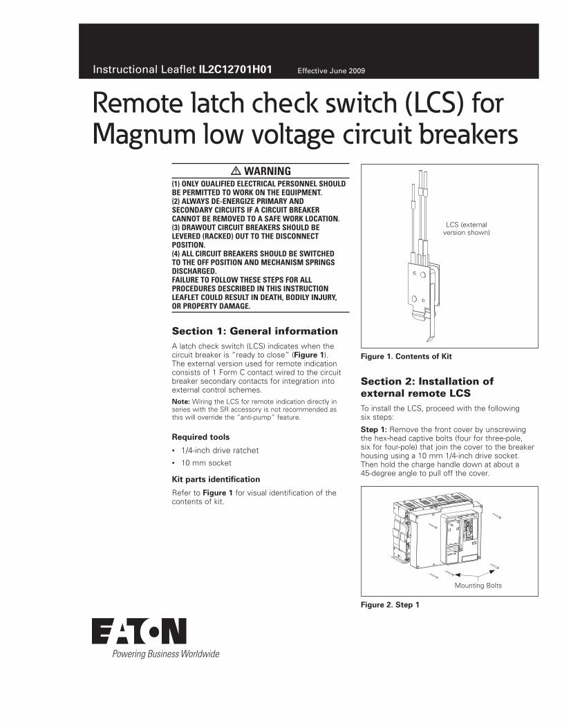
Remote latch check switch (LCS) forMagnum low voltage circuit breakers
warning(1) Only qualified electrical persOnnel shOuld be permitted tO wOrk On the equipment. (2) always de-energize primary and secOndary circuits if a circuit breaker cannOt be remOved tO a safe wOrk lOcatiOn. (3) drawOut circuit breakers shOuld be levered (racked) Out tO the discOnnect pOsitiOn. (4) all circuit breakers shOuld be switched tO the Off pOsitiOn and mechanism springs discharged. failure tO fOllOw these steps fOr all prOcedures described in this instructiOn leaflet cOuld result in death, bOdily injury, Or prOperty damage.
Section 1: General informationA latch check switch (LCS) indicates when the circuit breaker is “ready to close” (Figure 1). The external version used for remote indication consists of 1 Form C contact wired to the circuit breaker secondary contacts for integration into external control schemes.
Noee:N Wiring the LCS for remote indication directly in series with the SR accessory is not recommended as this will override the “anti-pump” feature.
Required oNNls
• 1/4-inch drive ratchet• 10 mm socket
Kio paros idenoificaoiNn
Refer to Figure 1 for visual identification of the contents of kit.
Figure 1. CNnoenos Nf Kio
Section 2: Installation of external remote LCSTo install the LCS, proceed with the following six steps:
Soep 1e: Remove the front cover by unscrewing the hex-head captive bolts (four for three-pole, six for four-pole) that join the cover to the breaker housing using a 10 mm 1/4-inch drive socket. Then hold the charge handle down at about a 45-degree angle to pull off the cover.
Figure 2. Soep 1
LCS (external version shown)
Mounting Bolts

EaoNn CNrpNraoiNnElectrical Sector1000 Cherrington ParkwayMoon Township, PA 15108United States877-ETN-CARE (877-386-2273)Eaton.com
© 2009 Eaton CorporationAll Rights ReservedPrinted in USAPublication No. IL2C12701HO1 / Z8679June 2009
PowerChain Management is a registered trademark of Eaton Corporation.
All other trademarks are property of their respective owners.
Instructional Leaflet IL2C12701H01Effective June 2009
Remote latch check switch (LCS) forMagnum low voltage circuit breakers
Soep 2e: Remove the accessory (if installed) from the indicated position on the accessory tray by lifting its lock up and sliding the accessory toward the front of the breaker. Then lift accessory up and out of tray. Do not disconnect the wiring.
Figure 3. Soep 2
Soep 3e: Connect three wires from the LCS to secondary block positions B28, B29, and B30 per wire markings. Check that all wire terminals are secure by pulling gently. Then push the LCS into center slot in the accessory tray. Make sure the LCS is fully seated.
Figure 4. Soep 3
Soep 4e: Reinstall any accessory that was removed in Step 2.
Soep 5e: Test the installation.
cautiOndO nOt tOuch the interiOr Of the breaker while the spring is charged. push the Off buttOn first tO ensure that the breaker is nOt clOsed. failure tO fOllOw this actiOn cOuld result in a seriOus injury.
Measure the continuity of the LCS with an Ohm meter during this step. With the breaker OPEN and DISCHARGED, push and release the OFF button. The LCS should not operate. This is indicated by the absence of an audible “click” from the switch. The Ohm meter verifies there is no change in continuity of the LCS contacts.
Remove This Accessory for Easier Access
Lock
LCS Secondary Block
Now charge the breaker using the manual charge handle. When the breaker is fully charged, repeat the above test by pushing the OFF button again. An audible “click” from the LCS should be heard and continuity as measured by the Ohm meter should change.
Figure 5. Soep 5
Soep 6e: Reinstall the front cover. Push the CLOSE and then the OPEN pushbuttons to discharge all energy from the mechanism, leaving it in an OPENED and DISCHARGED status.
Disclaimer of warranties and limitation of liabilityThe information, recommendations, descriptions, and safety notations in this document are based on Eaton Corporation’s (“Eaton”) experience and judgment, and may not cover all contingencies. If further information is required, an Eaton sales office should be consulted.
Sale of the product shown in this literature is subject to the terms and conditions outlined in appropriate Eaton selling policies or other contractual agreement between Eaton and the purchaser.
THERE ARE NO UNDERSTANDINGS, AGREEMENTS, WARRANTIES, EXPRESSED OR IMPLIED, INCLUDING WARRANTIES OF FITNESS FOR A PARTICULAR PURPOSE OR MERCHANTABILITY, OTHER THAN THOSE SPECIFICALLY SET OUT IN ANY EXISTING CONTRACT BETWEEN THE PARTIES. ANY SUCH CONTRACT STATES THE ENTIRE OBLIGATION OF EATON. THE CONTENTS OF THIS DOCUMENT SHALL NOT BECOME PART OF OR MODIFY ANY CONTRACT BETWEEN THE PARTIES.
In no event will Eaton be responsible to the purchaser or user in contract, in tort (including negligence), strict liability, or otherwise for any special, indirect, incidental, or consequential damage or loss whatsoever, including but not limited to damage or loss of use of equipment, plant or power system, cost of capital, loss of power, additional expenses in the use of existing power facilities, or claims against the purchaser or user by its customers resulting from the use of the information, recommendations, and descriptions contained herein.
The information contained in this manual is subject to change without notice.
Trip Latch Lever